Embed Size (px)
Citation preview
Hydro-Test Products Inc.85 Hudson RoadStow, MA 01775
Tel: 800-225-9488Fax: 978-897-1942www.hydro-test.com
Model SC-5 Instructional ManualThe economical and safe way to fill carbon dioxide cylinders
This manual includes instruction on operation, maintenance, troubleshooting and exploded view drawings for the Model SC-5 Carbon Dioxide Transfer Pump covering the following Part No’s:
Model No.Electrical Service
Allows pumping from:Voltage Phase Cycle(Hz)
560-040A1 115 1 60
High Pressure Cylinder50-100 Lb Standard CO2 Cylinder
560-040A2 230 1 60560-040B2 230 3 60560-040B4 460 3 60560-040C2 220 1 50560-040D1 115 1 60
Low Pressure Supply Tank(ie; 1 Ton Refrigerated Bulk Tank)
Minimum required outlet pressure of tank is 300 psi
560-040D2 230 1 60560-040E2 230 3 60560-040E4 460 3 60560-040F2 220 1 50
Tech Manual 15.23 rev. 3.1Revision date: March 2014
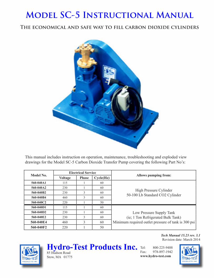
Model SC-5 Transfer Unit SpecificationsBore ..................................................................................... ........................................1"Stroke .................................................................................. .......................................2"Displacement ...................................................................... .........................1.57 cu. in.Pump Speed ........................................................................ ...........................175 RPMMax. Inlet Pressure ............................................................. ...........................1,000 PSIMax. Differential Pressure .................................................. ...........................1,000 PSIAverage Charging Rate of Speed ........................................ .......6 - 10 Lbs per minute
Motors are available in multiple configurations depending upon actual part no. of assembly - see front coverMotor Speed ........................................................................ ........................1,750 RPMMechanical Efficiency ........................................................ ...................................60%Volumetric Efficiency ......................................................... ...................................60%Operating Temperature Range ............................................ ..............................0 - 85°FSafety Disc Burst Pressure .................................................. ...................2650-3000 PSIShipping Weight .................................................................. ..............................180 LbsDimensions (crated) ............................................................ .........29"L x 17"W x 24"HDimensions (uncrated) ........................................................ ......26"L 16"W x 20 1/2"H
Section Subject Page Section Subject Page Figure Title Page1 Introduction & Description 4 4-2 Charging 7 1-1 Charging Unit and Accessories 3
1-1 Introduction 4 4-3 Water Test 7 1-2 Recharging Unit Assembly 5
1-2 Purpose 4 4-4 Shut-down 7 4-1 Recharging Unit Set Up for Operation 6
1+3 Description 4 5 Warning 8 4-2 Water Test 6
2 Special Service Equipment 4 5 Inspection, Lubrication and Maintenance 8 5-1 Peridic Inspection 8
2-1 Special Equipment 4 5-1 Periodic Inspection 8 5-2 Lubrication 8
3 Preperation for Use, Storage or Shipment 6 5-2 Lubrication 8 5-3 Crosshead Guide and Crank
Assembly 9
3-1 Unpacking 6 5-3 Drive Belt 8 5-4 Pump Assembly 103-2 Setting Up 6 5-4 Motor 8 5-5 Flip Valve 113-3 Preparartion for Use 6 5-5 Motor Thermal Units 8 6-1 Troubleshooting 123-4 Preparation for Storage 7 5-6 Pump Head 83-5 Preparation for Shipping 7 5-7 Piston Packings 114 Operating Instructions 7 5-8 Flip Valve 11
4-1 Connections for Filling 7 5-9 Crank Assembly 115-10 Earlier Models 12
6 Troubleshooting 12
Table of Contents List of Illustrations
Tech Manual 15.23 rev. 3.1Page 1
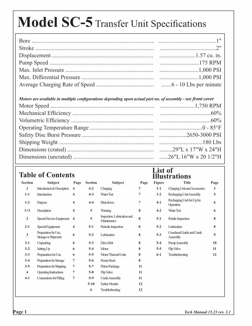
Note: The SC-5 Unit includes items shown in ( ). (0) indicates an optional item and is not included in the unit. These items can be ordered separately.
Item 1. Model SC-5 Transfer Pump (1)
Item 2. CO2 Cylinder Tilt Rack (0)Part No. 540-010 Ref No. 95275
Item 3. Hose Assembly with swivelsPart No. 210-009 Stainless braid Ref No. 95275 (2)Part No. 210-010 Bronze braid Ref No. 95275 (0) Mil Spec
Item 4. Manifold Assembly (1)Part No. 560-014 Ref No. 95296
Included Spare Parts Package:
Item 5. Hose Washer (10)Part No. 58-604 Ref. No. 50120
Item 6. Piston Packing Wrench (1) Part No. 240-047 Ref. No. 53778
Item 7. Piston Packing Leather (1) Part No. 58-605 Ref. No. 68686
Item 8. Piston Check (1)Part No. 240-038 Ref. No. 68687
Item 9. Piston Rod Packing Teflon(1) Part No. 240-044 Ref. No. 68717
Item 10. Safety Disc (1)Part No. 210-002 Ref. No. 50115
Item 11. Safety Disc Washer (1)Part No. 240-032 Ref. No. 50116
Item 12. Piston Rod Lubricant (1)Part No. 210-017 Ref. No. 99084
Item 13. Spanner Wrench (0)Part No. 210-024
Figure 1-1. Charging unit accessories
Item 14. Typical Fill Adapters (0)See Section 2-1
# 210-009Stainless Outer
Braid
# 210-010Bronze Outer
Braid
Tech Manual 15.23 rev. 3.1 Page 2
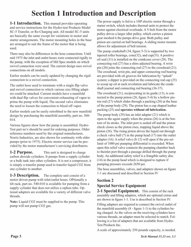
Section 1 Introduction and Description1-1 Introduction. This manual provides operating and service instructions for the Hydro-test Products Model SC-5 Transfer, or Re-Charging unit. All model SC-5 units are basically the same except for variations in motor and starter arrangements. The motor mounting holes in the base are arranged to suit the frame of the motor that is being used.There may also be differences in the hose connections. Until mid 1975 the inlet and outlet hoses were connected rigidly to the pump, with the exception of Mil Spec models on which swivel connection were used. The current design uses swivel connections on all models.Earlier models can be easily updated by changing the rigid connection to a swivel connection.The outlet hose used to terminate with a single flip valve and swivel connection to which various size filling adapt-ers could be attached. Current models have a manifold with dual flip valves for convenient exhausting of vapor to prime the pump with liquid, The second valve eliminates the need to loosen the connection to bleed off vapor.Earlier models can be easily retrofitted to the new manifold design by purchasing the manifold assembly, part no. 560-014.Various figures show how the pump is assembled. Hydro-Test part no’s should be used for ordering purposes. Older reference numbers used by the original manufacturer, Norris Industries, are also shown for continuity with older pumps (prior to 1975). Electric motor service can be pro-vided by the motor manufacturer’s servicing distributors.
1-2 Purpose. This unit is designed to charge carbon dioxide cylinders. It pumps from a supply cylinder or a bulk tank into other cylinders. It is not a compressor, it is simply a transfer pump used to transfer liquid CO2 from one cylinder to another.
1-3 Description. The complete unit consist of a motor driven pump with inlet/outlet hoses. OPtionally a tilt rack, part no. 540-010 is available for pumping from a supply cylinder that does not utilize a siphon tube. Op-tional adapters are available for a variety of different valve threads.Note: Liquid CO2 must be supplied to the pump. This pump will not pump CO2 gas.
The power supply is fed to a 1HP electric motor through a starter switch, which includes thermal units to protect the motor against electrical overloads. A V-belt from the motor pulley drives a larger idler pulley, which carries a pinion gear meshed ti the pumps drive gear. Both pulley and pinion are carried on ball bearings. A sliding motor mounts allows for adjustment of belt tension.The pump crankshaft (34, figure 5-3) is supported by two tapered roller bearings, cone(32), and cup(33). A positive oil seal (31) is installed on the crankcase cover (28). The connecting rod (27) has a shim adjusted bearing. A wrist pin (20) joins the connecting rod (27) to the crosshead (21). The crosshead, wrist pin, and upper connecting rod bearing are provided with oil grooves for lubrication by “splash” system; a dipper is provided on the connecting rod cap (25) to scoop up oil at each revolution and lubricate the crank-shaft journal and connecting rod bearing (36-37).The crosshead (21), reciprocating in its guide (13), is con-nected to the pump piston (26, figure 5-4) by a hollow pis-ton rod (27) which slides through a packing (20) at the base of the pump body (29). The piston has a cup shaped leather packing (25) and operates without oil lubrication.The pump body (29) has an inlet adapter (21) which is open to the agent supply when the piston (26) is at the bot-tom of its stroke. The inlet port is sealed off and the piston check closes as the piston rises, trapping liquid above the piston (26). The rising piston drives the liquid out through a check valve ball (7) in the pump head (17) into the outlet adapter (16). A relief valve (8-12) will open if the pre-set limit of 1000 psi pumping differential is exceeded. When open this relief valve connects the pumping chamber back to theinlet port through a passage drilled through the pump body. An additional safety relief is a frangible safety disc (14) in the pump head which is designed to rupture if pumping pressure exceeds 2650 psi.The hose assemblies, valves, and adapters shown on figure 1-1 are discussed and described in Section IV
Section 2Special Service Equipment2-1 Special Equipment. This consist of the rack assembly and filling adapters, which are optional extras and are shown in figure 1-1. Use is described in Section IV.Filling adapters are required to connect the swivel outlet of the manifold assembly (8 - figure 1-1) to the cylinders be-ing charged. As the valves on the receiving cylinders have various threads, an adapter must be selected to match. Fol-lowing is a list of adapters that are available from Hydro-Test Products Inc.A scale of approximately 250 pounds capacity, is needed.
Tech Manual 15.23 rev. 3.1Page 3
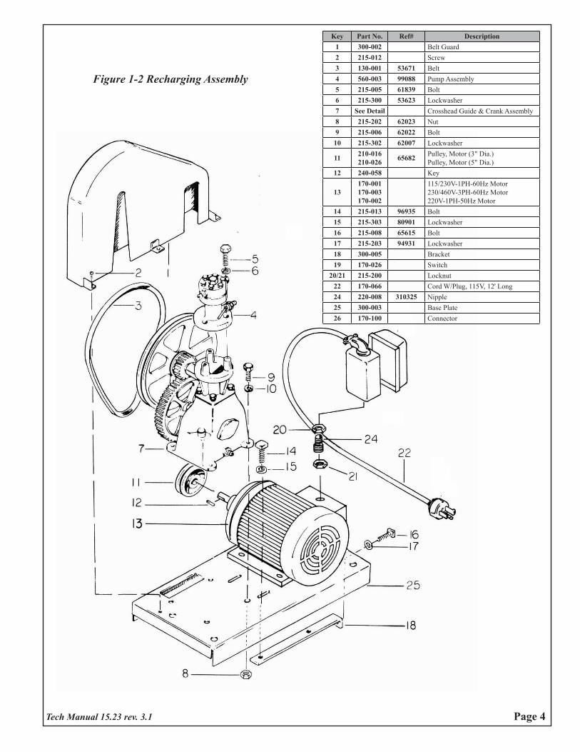
Key Part No. Ref# Description1 300-002 Belt Guard2 215-012 Screw3 130-001 53671 Belt4 560-003 99088 Pump Assembly5 215-005 61839 Bolt6 215-300 53623 Lockwasher7 See Detail Crosshead Guide & Crank Assembly8 215-202 62023 Nut9 215-006 62022 Bolt10 215-302 62007 Lockwasher
11 210-016210-026 65682 Pulley, Motor (3" Dia.)
Pulley, Motor (5" Dia.)12 240-058 Key
13170-001170-003170-002
115/230V-1PH-60Hz Motor230/460V-3PH-60Hz Motor220V-1PH-50Hz Motor
14 215-013 96935 Bolt15 215-303 80901 Lockwasher16 215-008 65615 Bolt17 215-203 94931 Lockwasher18 300-005 Bracket19 170-026 Switch
20/21 215-200 Locknut22 170-066 Cord W/Plug, 115V, 12' Long24 220-008 310325 Nipple25 300-003 Base Plate26 170-100 Connector
Figure 1-2 Recharging Assembly
Tech Manual 15.23 rev. 3.1 Page 4
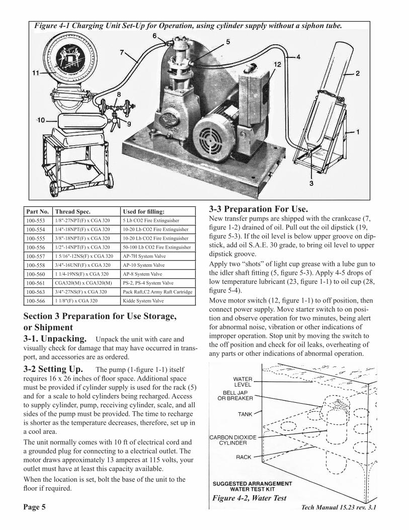
Figure 4-1 Charging Unit Set-Up for Operation, using cylinder supply without a siphon tube.
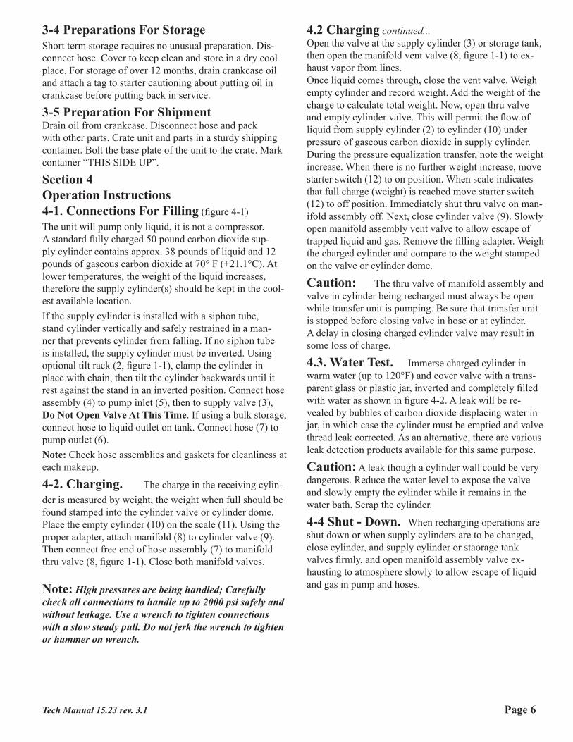
Figure 4-2, Water Test
Part No. Thread Spec. Used for filling:100-553 1/8"-27NPT(F) x CGA 320 5 Lb CO2 Fire Extinguisher
100-554 1/4"-18NPT(F) x CGA 320 10-20 Lb CO2 Fire Extinguisher
100-555 3/8"-18NPT(F) x CGA 320 10-20 Lb CO2 Fire Extinguisher
100-556 1/2"-14NPT(F) x CGA 320 50-100 Lb CO2 Fire Extinguisher
100-557 1 5/16"-12NS(F) x CGA 320 AP-7H System Valve
100-558 3/4"-16UNF(F) x CGA 320 AP-10 System Valve
100-560 1 1/4-19NS(F) x CGA 320 AP-8 System Valve
100-561 CGA320(M) x CGA320(M) PS-2, PS-4 System Valve
100-563 3/4"-27NS(F) x CGA 320 Pack Raft,C2 Army Raft Cartridge
100-566 1 1/8"(F) x CGA 320 Kidde System Valve
Section 3 Preparation for Use Storage, or Shipment3-1. Unpacking. Unpack the unit with care and visually check for damage that may have occurred in trans-port, and accessories are as ordered.
3-2 Setting Up. The pump (1-figure 1-1) itself requires 16 x 26 inches of floor space. Additional space must be provided if cylinder supply is used for the rack (5) and for a scale to hold cylinders being recharged. Access to supply cylinder, pump, receiving cylinder, scale, and all sides of the pump must be provided. The time to recharge is shorter as the temperature decreases, therefore, set up in a cool area.The unit normally comes with 10 ft of electrical cord and a grounded plug for connecting to a electrical outlet. The motor draws approximately 13 amperes at 115 volts, your outlet must have at least this capacity available.When the location is set, bolt the base of the unit to the floor if required.
3-3 Preparation For Use.New transfer pumps are shipped with the crankcase (7, figure 1-2) drained of oil. Pull out the oil dipstick (19, figure 5-3). If the oil level is below upper groove on dip-stick, add oil S.A.E. 30 grade, to bring oil level to upper dipstick groove.Apply two “shots” of light cup grease with a lube gun to the idler shaft fitting (5, figure 5-3). Apply 4-5 drops of low temperature lubricant (23, figure 1-1) to oil cup (28, figure 5-4).Move motor switch (12, figure 1-1) to off position, then connect power supply. Move starter switch to on posi-tion and observe operation for two minutes, being alert for abnormal noise, vibration or other indications of improper operation. Stop unit by moving the switch to the off position and check for oil leaks, overheating of any parts or other indications of abnormal operation.
Tech Manual 15.23 rev. 3.1Page 5
3-4 Preparations For StorageShort term storage requires no unusual preparation. Dis-connect hose. Cover to keep clean and store in a dry cool place. For storage of over 12 months, drain crankcase oil and attach a tag to starter cautioning about putting oil in crankcase before putting back in service.
3-5 Preparation For ShipmentDrain oil from crankcase. Disconnect hose and pack with other parts. Crate unit and parts in a sturdy shipping container. Bolt the base plate of the unit to the crate. Mark container “THIS SIDE UP”.
Section 4Operation Instructions4-1. Connections For Filling (figure 4-1)The unit will pump only liquid, it is not a compressor. A standard fully charged 50 pound carbon dioxide sup-ply cylinder contains approx. 38 pounds of liquid and 12 pounds of gaseous carbon dioxide at 70° F (+21.1°C). At lower temperatures, the weight of the liquid increases, therefore the supply cylinder(s) should be kept in the cool-est available location.If the supply cylinder is installed with a siphon tube, stand cylinder vertically and safely restrained in a man-ner that prevents cylinder from falling. If no siphon tube is installed, the supply cylinder must be inverted. Using optional tilt rack (2, figure 1-1), clamp the cylinder in place with chain, then tilt the cylinder backwards until it rest against the stand in an inverted position. Connect hose assembly (4) to pump inlet (5), then to supply valve (3), Do Not Open Valve At This Time. If using a bulk storage, connect hose to liquid outlet on tank. Connect hose (7) to pump outlet (6).Note: Check hose assemblies and gaskets for cleanliness at each makeup.
4-2. Charging. The charge in the receiving cylin-der is measured by weight, the weight when full should be found stamped into the cylinder valve or cylinder dome. Place the empty cylinder (10) on the scale (11). Using the proper adapter, attach manifold (8) to cylinder valve (9). Then connect free end of hose assembly (7) to manifold thru valve (8, figure 1-1). Close both manifold valves.
Note: High pressures are being handled; Carefully check all connections to handle up to 2000 psi safely and without leakage. Use a wrench to tighten connections with a slow steady pull. Do not jerk the wrench to tighten or hammer on wrench.
4.2 Charging continued...Open the valve at the supply cylinder (3) or storage tank, then open the manifold vent valve (8, figure 1-1) to ex-haust vapor from lines.Once liquid comes through, close the vent valve. Weigh empty cylinder and record weight. Add the weight of the charge to calculate total weight. Now, open thru valve and empty cylinder valve. This will permit the flow of liquid from supply cylinder (2) to cylinder (10) under pressure of gaseous carbon dioxide in supply cylinder. During the pressure equalization transfer, note the weight increase. When there is no further weight increase, move starter switch (12) to on position. When scale indicates that full charge (weight) is reached move starter switch (12) to off position. Immediately shut thru valve on man-ifold assembly off. Next, close cylinder valve (9). Slowly open manifold assembly vent valve to allow escape of trapped liquid and gas. Remove the filling adapter. Weigh the charged cylinder and compare to the weight stamped on the valve or cylinder dome.
Caution: The thru valve of manifold assembly and valve in cylinder being recharged must always be open while transfer unit is pumping. Be sure that transfer unit is stopped before closing valve in hose or at cylinder. A delay in closing charged cylinder valve may result in some loss of charge.
4.3. Water Test. Immerse charged cylinder in warm water (up to 120°F) and cover valve with a trans-parent glass or plastic jar, inverted and completely filled with water as shown in figure 4-2. A leak will be re-vealed by bubbles of carbon dioxide displacing water in jar, in which case the cylinder must be emptied and valve thread leak corrected. As an alternative, there are various leak detection products available for this same purpose.
Caution: A leak though a cylinder wall could be very dangerous. Reduce the water level to expose the valve and slowly empty the cylinder while it remains in the water bath. Scrap the cylinder.
4-4 Shut - Down. When recharging operations are shut down or when supply cylinders are to be changed, close cylinder, and supply cylinder or staorage tank valves firmly, and open manifold assembly valve ex-hausting to atmosphere slowly to allow escape of liquid and gas in pump and hoses.
Tech Manual 15.23 rev. 3.1 Page 6
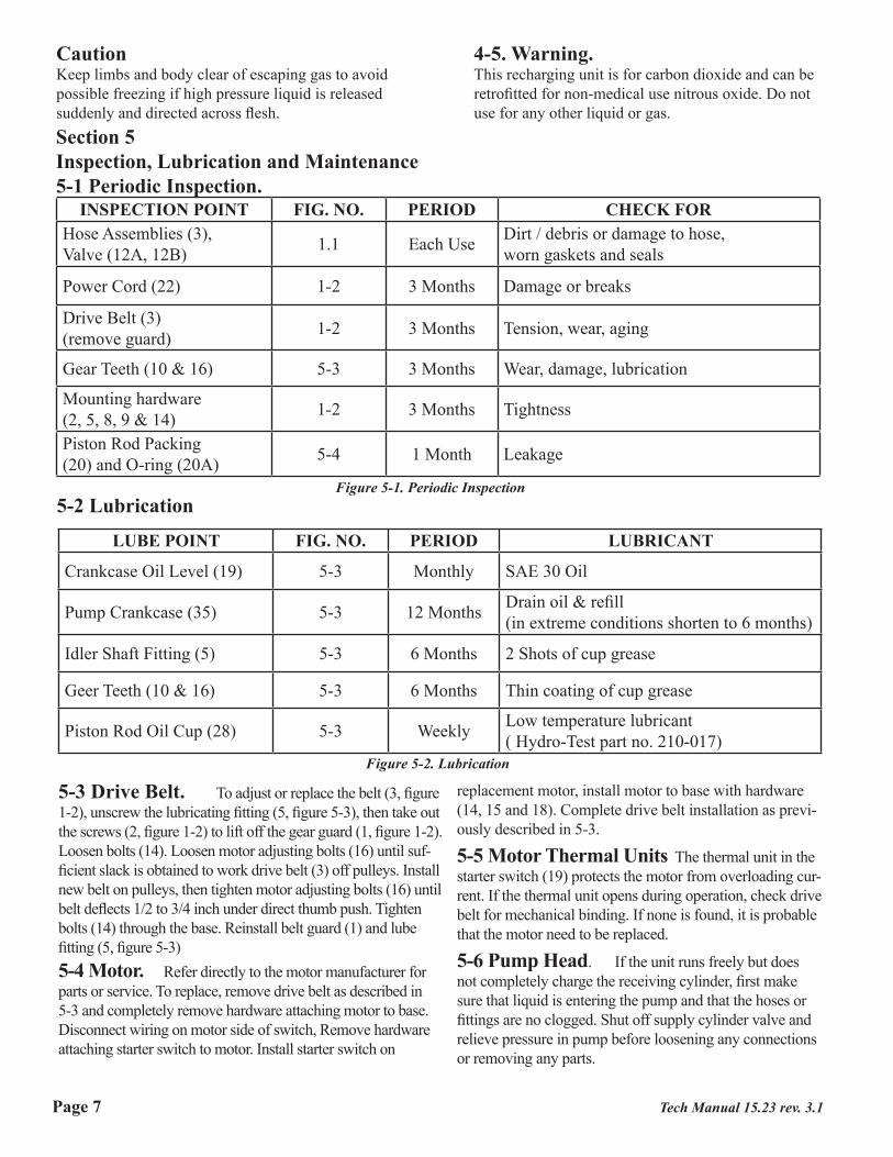
CautionKeep limbs and body clear of escaping gas to avoid possible freezing if high pressure liquid is released suddenly and directed across flesh.
4-5. Warning.This recharging unit is for carbon dioxide and can be retrofitted for non-medical use nitrous oxide. Do not use for any other liquid or gas.
Section 5Inspection, Lubrication and Maintenance5-1 Periodic Inspection.
INSPECTION POINT FIG. NO. PERIOD CHECK FORHose Assemblies (3), Valve (12A, 12B) 1.1 Each Use Dirt / debris or damage to hose,
worn gaskets and seals
Power Cord (22) 1-2 3 Months Damage or breaks
Drive Belt (3)(remove guard) 1-2 3 Months Tension, wear, aging
Gear Teeth (10 & 16) 5-3 3 Months Wear, damage, lubrication
Mounting hardware(2, 5, 8, 9 & 14) 1-2 3 Months Tightness
Piston Rod Packing(20) and O-ring (20A) 5-4 1 Month Leakage
Figure 5-1. Periodic Inspection
LUBE POINT FIG. NO. PERIOD LUBRICANT
Crankcase Oil Level (19) 5-3 Monthly SAE 30 Oil
Pump Crankcase (35) 5-3 12 Months Drain oil & refill(in extreme conditions shorten to 6 months)
Idler Shaft Fitting (5) 5-3 6 Months 2 Shots of cup grease
Geer Teeth (10 & 16) 5-3 6 Months Thin coating of cup grease
Piston Rod Oil Cup (28) 5-3 Weekly Low temperature lubricant( Hydro-Test part no. 210-017)
5-2 Lubrication
Figure 5-2. Lubrication
5-3 Drive Belt. To adjust or replace the belt (3, figure 1-2), unscrew the lubricating fitting (5, figure 5-3), then take out the screws (2, figure 1-2) to lift off the gear guard (1, figure 1-2). Loosen bolts (14). Loosen motor adjusting bolts (16) until suf-ficient slack is obtained to work drive belt (3) off pulleys. Install new belt on pulleys, then tighten motor adjusting bolts (16) until belt deflects 1/2 to 3/4 inch under direct thumb push. Tighten bolts (14) through the base. Reinstall belt guard (1) and lube fitting (5, figure 5-3)5-4 Motor. Refer directly to the motor manufacturer for parts or service. To replace, remove drive belt as described in 5-3 and completely remove hardware attaching motor to base. Disconnect wiring on motor side of switch, Remove hardware attaching starter switch to motor. Install starter switch on
replacement motor, install motor to base with hardware (14, 15 and 18). Complete drive belt installation as previ-ously described in 5-3.
5-5 Motor Thermal Units The thermal unit in the starter switch (19) protects the motor from overloading cur-rent. If the thermal unit opens during operation, check drive belt for mechanical binding. If none is found, it is probable that the motor need to be replaced.
5-6 Pump Head. If the unit runs freely but does not completely charge the receiving cylinder, first make sure that liquid is entering the pump and that the hoses or fittings are no clogged. Shut off supply cylinder valve and relieve pressure in pump before loosening any connections or removing any parts.
Tech Manual 15.23 rev. 3.1Page 7
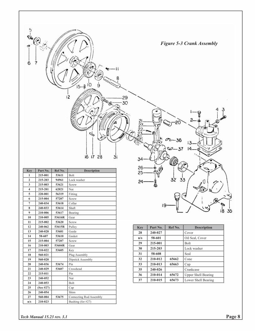
Key Part No. Ref No. Description28 240-027 Covern/s 58-601 Oil Seal, Cover29 215-001 Bolt30 215-203 Lock washer31 58-608 Seal32 210-012 65662 Cone33 210-013 65663 Cup35 240-026 Crankcase36 210-014 65672 Upper Shell Bearing37 210-015 65673 Lower Shell Bearing
Key Part No. Ref No. Description1 215-001 53611 Bolt2 215-203 94961 Lock washer3 215-003 53621 Screw4 215-201 62021 Nut5 220-001 56319 Fitting6 215-004 57207 Screw7 240-034 53618 Collar8 240-033 53614 Shaft9 210-006 53617 Bearing
10 210-005 53616R Gear11 215-002 53620 Screw12 240-062 53615R Pulley13 240-028 53681 Guide14 58-607 53610 Gasket15 215-004 57207 Screw16 210-003 53604R Gear17 210-022 53605 Key18 560-021 Plug Assembly19 560-020 Dipstick Assembly20 240-036 53674 Pin21 240-029 53607 Crosshead22 215-011 Pin23 240-052 Nut24 240-053 Bolt25 (See #27) Cap26 240-054 Shim27 560-004 53675 Connecting Rod Assemblyn/s 210-023 Bushing (for #27)
Figure 5-3 Crank Assembly
Tech Manual 15.23 rev. 3.1 Page 8
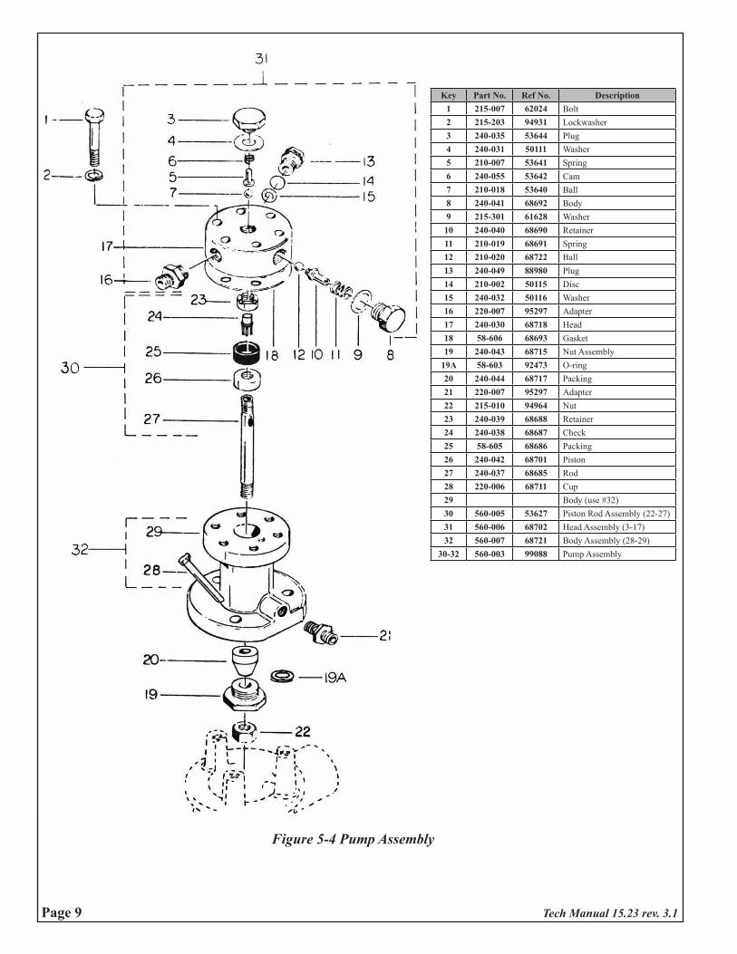
Figure 5-4 Pump Assembly
Key Part No. Ref No. Description1 215-007 62024 Bolt2 215-203 94931 Lockwasher3 240-035 53644 Plug4 240-031 50111 Washer5 210-007 53641 Spring6 240-055 53642 Cam7 210-018 53640 Ball8 240-041 68692 Body9 215-301 61628 Washer10 240-040 68690 Retainer11 210-019 68691 Spring12 210-020 68722 Ball13 240-049 88980 Plug14 210-002 50115 Disc15 240-032 50116 Washer16 220-007 95297 Adapter17 240-030 68718 Head18 58-606 68693 Gasket19 240-043 68715 Nut Assembly
19A 58-603 92473 O-ring20 240-044 68717 Packing21 220-007 95297 Adapter22 215-010 94964 Nut23 240-039 68688 Retainer24 240-038 68687 Check25 58-605 68686 Packing26 240-042 68701 Piston27 240-037 68685 Rod28 220-006 68711 Cup29 Body (use #32)30 560-005 53627 Piston Rod Assembly (22-27)31 560-006 68702 Head Assembly (3-17)32 560-007 68721 Body Assembly (28-29)
30-32 560-003 99088 Pump Assembly
Tech Manual 15.23 rev. 3.1Page 9
If the unit still does not pump to capacity, unscrew outlet valve plug (3, figure 5-4) to lift out washer (4), cam (5), spring (6) and ball (7). Check parts for debris which could prevent the valve from opening and closing easily. Also inspect the ball for nicks, which require ball replacement.Inspect the ball seat in head (17). This is a pressed-in insert. If the insert has been dislodged, the pump head needs to be replaced. If the seat surface is nicked, replacing the ball and striking it a sharp tap with a small hammer will “coin” the seat to a proper seal. If not, the head needs to be replaced.Pumping capacity can also suffer if the by pass valve in the head leaks or is obstructed. Remove plug (8) to lift out washer (9), spring (11), retainer (10), and ball (12). Clean or replace as necessary. Inspect the ball seat in the head (17), If dirty, clean. If dented, insert the ball (12) and “coin” with a hammer tap. Otherwise the head (17) needs to be replaced.The safety disc (14) in the pump head will relieve if pump pressure reaches 2650 psi. It is replaced by unscrewing plug (13). Always sandwich the disc between the plug (13 and washer (15). Never use more than one disc or any other part just because it fits. The disc must be of proper pressure and material to relieve properly. If this maintenance does not cure pumping inefficiency, refer to section 5-7 for service of packing.
5-7 Piston Packing(s). Careful maintenance of the piston rod assembly is the key to efficient and reliable per-formance. The piston packing (25, figure 5-4) must be soft, flexible, free of debris that will score the pump body (29). A scored pump body must be replaced. The packing must be sandwiched tightly between the piston(26) and retainer (23). The retainer (23) with check (24) inserted, must be screwed down on the piston rod (27) with the wrench (16, figure 1-1) until it bottoms on the inside shoulder, and the piston (26) must be tightened to firmly compress the packing (25) against the retainer (23), using a 5/32” drill as a wrench. The check (24) must float freely in the retainer (23). If it binds or is blocked with debris, the pump will not transfer. It helps to stake the piston (26) to the piston rod (27) with a center punch at two points on the piston rod thread to prevent loos-ening, A loose will prevent transfer.To service the piston assembly, remove pump head bolts (1, figure 5-4) and lift off head (17) and gasket (18). Loosen nut (22) and remove bolts (5, figure 1-2) attaching pump body (29, figure 5-4) to crosshead guide (13, figure 5-3). Raise body to unscrew piston rod from crosshead (21). Unscrew nut (22, figure 5-4) and packing nut (19) to remove piston rod packing (20), Be careful to avoid damaging o-ring (19A) on body threads. Remove piston assembly from pump body. The piston rod (27) has a polished finish that must never be gripped with a toothed wrench as a rough surface will quickly damage the piston rod packing (20) and cause leaks.
If the piston rod is to be held in a vise, use a lead or copper pads on the vise jaws. A 3/16” drill bit through the holes in the rod serve as a vise. Use wrench (16, figure 1-1) to unscrew retainer(23, figure 5-4). Remove check (24) and packing (25).Re-assemble in reverse order. Piston check (24) must move freely in retainer (23).After the piston assembly is back in he body, slide the piston rod packing (20) over the piston rod threads into the body recess. Thread in the packing nut (19) until it seats firmly. Do not overtighten - it serves no purpose as the packing (20) is not compressible. Overtightening will wear out the packing prematurely.Thread the locknut (22) up on the piston rod (27) as far as possible, then bolt body (29) to crosshead guide 13, figure 5-3). Screw piston rod (27, figure 5-4) into crosshead (21, figure 5-3) until top of retainer (23, figure 5-4) is slightly below the plane of the body (29), using a straight edge across the body opening as a guide, slow;y rock the crank by hand by moving the large pulley through top dead cen-ter to check height of piston check (24). If the check is too high, the check will strike the pump head and damage the pump head seal.When adjusted, tighten lock nut (22). Install new gasket (18) on body (19). making sure that all holes are aligned. Install pump head assembly, also with all holes aligned and bolt securely.
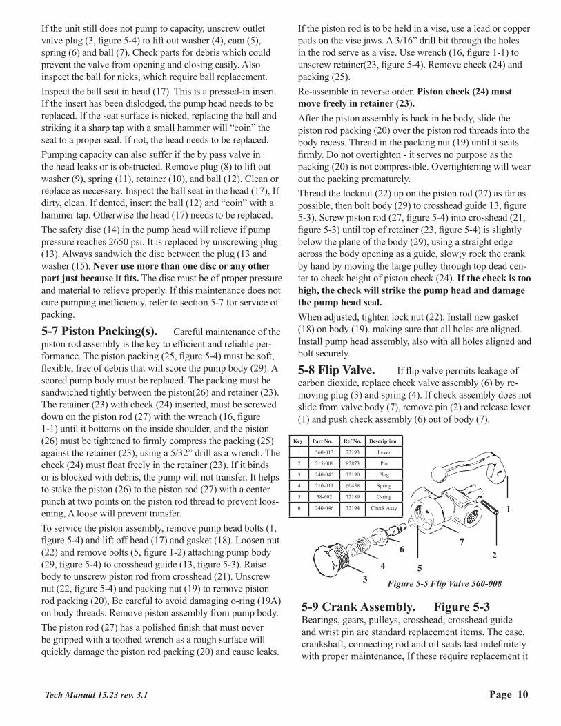
5-8 Flip Valve. If flip valve permits leakage of carbon dioxide, replace check valve assembly (6) by re-moving plug (3) and spring (4). If check assembly does not slide from valve body (7), remove pin (2) and release lever (1) and push check assembly (6) out of body (7).
1
2
34
6
5
7
Figure 5-5 Flip Valve 560-008
Key Part No. Ref No. Description
1 560-013 72193 Lever
2 215-009 82873 Pin
3 240-045 72190 Plug
4 210-011 60458 Spring
5 58-602 72189 O-ring
6 240-046 72194 Check Assy
5-9 Crank Assembly. Figure 5-3Bearings, gears, pulleys, crosshead, crosshead guide and wrist pin are standard replacement items. The case, crankshaft, connecting rod and oil seals last indefinitely with proper maintenance, If these require replacement it
Tech Manual 15.23 rev. 3.1 Page 10
Hydro-Test Products Inc.85 Hudson RoadStow, MA 01775
Tel: 800-225-9488Fax: 978-897-1942www.hydro-test.com
it is likely that other major parts also require replace-ment, to the extent that the labor and material cost will out weight the purchase of a new unit. Accordingly these parts are normally not available.
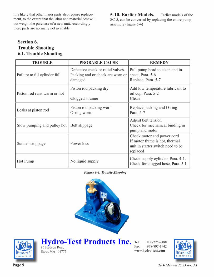
5-10. Earlier Models. Earlier models of the SC-5, can be converted by replacing the entire pump assembly (figure 5-4)
Section 6.Trouble Shooting6.1. Trouble Shooting
TROUBLE PROBABLE CAUSE REMEDY
Failure to fill cylinder fullDefective check or relief valves.Packing and or check are worn or damaged
Pull pump head to clean and in-spect, Para. 5-6Replace, Para. 5-7
Piston rod runs warm or hotPiston rod packing dry
Clogged strainer
Add low temperature lubricant to oil cup, Para. 5-2Clean
Leaks at piston rod Piston rod packing wornO-ring worn
Replace packing and O-ringPara. 5-7
Slow pumping and pulley hot Belt slippageAdjust belt tensionCheck for mechanical binding in pump and motor
Sudden stoppage Power loss
Check motor and power cordIf motor frame is hot, thermal unit in starter switch need to be replaced
Hot Pump No liquid supply Check supply cylinder, Para. 4-1.Check for clogged hose, Para. 5.1.
Figure 6-1. Trouble Shooting
Tech Manual 15.23 rev. 3.1Page 9