Embed Size (px)
Citation preview
MODEL QTC4 AIR-COOLED SCREW CHILLERS
150 - 360 Tons2 Compressor
60 HzHFC-134a
or HFC-513A
FORM QTC4-EG1 (817)
QUANTECH
FORM QTC4-EG1 (817)
2
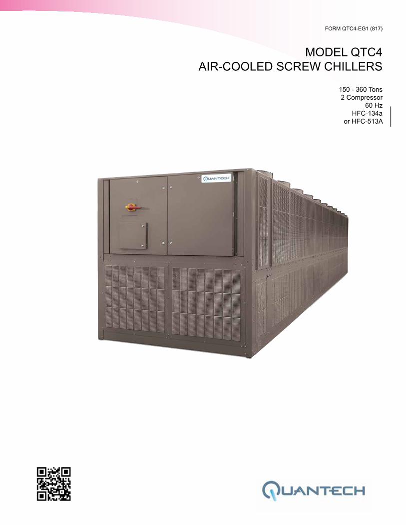
Nomenclature
Approvals
• ASME Boiler and Pressure Vessel Code – Section Vlll Division 1.
• AHRI Standard 550/590 and 551/591.
• UL 1995 – Heating and Cooling Equipment
• ASHRAE 15 – Safety Code for Mechanical Refrigeration
• ASHRAE Guideline 3 – Reducing Emission of Halogenated Refrigerants in Refrigeration and Air-Conditioning Equipment and Systems
• N.E.C. – National Electrical Code
• OSHA – Occupational Safety and Health Act
QTC4 210 SAXX 46 A A
VOLTAGE CODE-17 = 208-3-60-28 = 230-3-60-40 = 380-3-60-42 = 400-3-60-46 = 460-3-60-58 = 575-3-60
CONFIGURATIONCondenser CodeEvaporator CodeCompressor CodeCondenser Fan & Sound Kit Code
DEVELOPMENT LEVEL
REFRIGERANT A= HFC-134aB = HFC-513A
QTC4 = Quantech Chiller Air Cooled Screw
MODEL NUMBER
FORM QTC4-EG1 (817)
QUANTECH 3
Table of Contents
INTRODUCTION ...................................................................................................................................................... 5
UNIT OVERVIEW ..................................................................................................................................................... 6
QTC4 CONTROL CENTER ..................................................................................................................................... 9
ACCESSORIES AND OPTIONS ........................................................................................................................... 11
REFRIGERANT FLOW DIAGRAM ........................................................................................................................ 17
APPLICATION DATA ............................................................................................................................................. 18
PHYSICAL DATA - MICROCHANNEL COIL ......................................................................................................... 24
EVAPORATOR OPTIONS ...................................................................................................................................... 26
DIMENSIONS ......................................................................................................................................................... 32
ISOLATOR LOCATIONS ....................................................................................................................................... 34
ISOLATORS ........................................................................................................................................................... 40
ELECTRICAL DATA .............................................................................................................................................. 43
POWER WIRING .................................................................................................................................................... 46
CUSTOMER CONTROL WIRING .......................................................................................................................... 48
CONTROL WIRING ............................................................................................................................................... 50
GUIDE SPECIFICATIONS ..................................................................................................................................... 52
QUANTECH
FORM QTC4-EG1 (817)
4
THIS PAGE INTENTIONALLY LEFT BLANK.
FORM QTC4-EG1 (817)
QUANTECH 5
Quantech™ has raised the bar of chiller design and customer expectations. We are rais-ing the bar again with a leap forward in air-cooled chiller technology. Continuing the his-tory of innovation in both compressor design and Variable Speed Drive (VSD) technology, Quantech proudly introduces the QTC4.
In the past, the choice to use an air-cooled chiller came with the expectation of compro-mise, where simplicity of design and maintenance were traded for performance and ef-ficiency. The new QTC4 provides a better balance by combining the best of both - a high performance design that minimizes the total cost of ownership.
Quantech QTC4 model air-cooled chillers provide superior performance. Higher efficiency heat exchangers coupled with variable speed operation and smart controls elevate the system efficiency to a whole new level. The resulting benefit from QTC4 chillers is much greater than the sum of its parts.
Efficiency: Reduce your consumption - QTC4 chillers are Quantech's most efficient air-cooled chillers. The design offers a lighter, smaller and quieter package that minimizes the installed cost and maximizes usable building space. QTC4 chillers are simpler in design with easy access to service components for reliable operation and efficient main-tenance. With up to a 40% improvement in real world efficiency versus current products, QTC4 sets the new standards for lowering energy use.
Sustainability: Improve your environmental footprint - QTC4 lowers both direct and indirect impact on the environment. It uses a refrigerant that has zero ozone depletion po-tential (ODP). The design minimizes the quantity of refrigerant used in the system. Every QTC4 model helps LEED projects earn the Energy and Atmosphere Credit 4. The highest portion of green house gases is carbon dioxide generated from electric power plants. HVAC systems are one of the largest consumers of electricity in commercial buildings. QTC4 chill-ers reduce the electricity usage, thereby contributing to reducing greenhouse gases and helping keep the planet cool.
Low Sound: Quiet operation makes you a good neighbor - The variable speed tech-nology on QTC4 allows unparalleled low sound levels at off peak design conditions. This makes QTC4 a great solution for sound sensitive zones. Several acoustic attenuation op-tions such as smart controls (SilentNight™), aerodynamic fans, and effective sound enclo-sures allow the chiller to meet even the most stringent sound level requirements.
Confidence: Proven performance provides peace of mind - QTC4 design is proven by years of success with the previous generation of VSD air-cooled screw chillers with thou-sands of machines operating in more than one hundred countries.
QTC4 is configurable to be the perfect fit for your unique needs. QTC4 offers an array of options that can be tailored and tuned to match the capacity, efficiency, sound and footprint for your specific application. Several variations of condenser fans, evaporator arrangements, sound kits, protection enclosures, and controls schemes are available to meet specific requirements for your site.
Introduction
QTC4 chillers are Quantech's most efficient air-cooled chillers. The design offers a lighter, smaller and quieter package that mini-mizes the installed costs.
QUANTECH
FORM QTC4-EG1 (817)
6
Unit Overview
SEMI-HERMETIC QUANTECH TWIN SCREW COMPRESSORS
The direct-drive, semi-hermetic rotary twin-screw compressors incorporate advanced technology in a rugged design. The continuous function, microprocessor controlled VSD provides smooth capacity control from 100% down to 10% of chiller capacity. State-of-the-art technology, obtained from decades of screw compressor design and manufacturing, ensures optimal efficiencies at all chiller load points. With no unloading steps or slide valves in the compressors, the QTC4 variable speed driven compressors have 50% fewer moving parts than fixed speed compressors with slide valves. The QTC4 compressor is one of the most efficient and reliable screw compressors in the industry.
EVAPORATOR
The evaporator is a shell and tube, hybrid falling film type heat exchanger. It contains a balance of flooded and falling film technology to optimize efficiency, minimize refrigerant charge, and maintain reliable control. A specifically designed distribution system provides uniform refrigerant flow for optimum performance.
CONDENSER
The QTC4 introduces the microchannel coil to the Quantech screw compressor chiller line. Microchannel coils are made of a single material to avoid galvanic corrosion due to dissimilar metals. Coils and headers are brazed as one piece, minimizing leaks. The inherently rugged coil construction, which includes non-overhanging fins, eliminates the possibility of fin damage. The microchannel maximizes condenser heat transfer, resulting in a smaller footprint, and reduces refrigerant charge by as much as 50%. The design working pressure of the microchannel condenser is 375 PSIG (25.9 bar).
The condenser fans are composed of corrosion resistant aluminum hub and glass-fiber-reinforced polypropylene composite blades molded into a low-noise airfoil section. All blades are statically and dynamically balanced for vibration-free operation. Fan motors are Totally Enclosed Air-Over (TEAO), squirrel-cage type and current protected. The di-rect drive motors feature double-sealed and permanently lubricated ball bearings, cutting down on maintenance cost over the life of the unit.
REFRIGERANT CIRCUIT
The QTC4 has one independent refrigerant circuit per compressor. Each circuit uses cop-per refrigerant pipe formed on computer-controlled bending machines. By using com-puter-aided technology, over 60% of system piping brazed joints have been eliminated (as compared to designs that use fittings), resulting in a highly reliable and leak-resistant system.
COMPLETE FACTORY PACKAGE
Each unit is shipped as a complete factory package, completely assembled with all in-terconnecting refrigerant piping and internal wiring and ready for field installation. Prior to shipment, each individual chiller undergoes an extensive testing procedure, ensuring workmanship is the highest quality and that the initial start-up is trouble-free.
FORM QTC4-EG1 (817)
QUANTECH 7
Before leaving the factory, each refrigerant circuit is factory pressure tested, evacuated and then fully charged with refrigerant and oil. An operational test is performed with water flowing through the evaporator to ensure each circuit functions correctly.
ELECTRICAL
All controls and motor starting equipment necessary for unit operation are factory wired and function tested. There are no surprises when you go to start-up; you can have confi-dence that the unit will start up right the first time and every time.
The chillers are available with a single point power connection and are supplied with a fac-tory mounted and wired control transformer that powers all unit controls from the main unit power supply. The transformer utilizes scheduled line voltage on the primary side and pro-vides 115V/1Ø on secondary. The standard unit is equipped with terminal block electrical connections. All exposed power wiring is routed through liquid-tight, UV-stabilized, non-metallic conduit. Selection of model 370 is standard dual point, with single point option.
VSD Power/Control Panel includes main power connection(s), VSD and fan motor con-tactors, current overloads, and factory wiring. All display and control features can be ac-cessed through the keypad and control display access door, eliminating the need to open the main cabinet doors.
BUILDING AUTOMATION SYSTEM CAPABILITIES
The QTC4 chiller comes standard with native communication capability for BACnet (MS/TP), Modbus and N2, with optional capabilities available for LON. The standard unit capabilities include built-in-scheduling, remote start-stop, remote water temperature reset and up to two steps of demand (load) limiting depending on model. The standard control panel can be directly connected to a Building Automated System via the standard factory-installed RS232 communication port.
For connection with Building Automated System Connected Services, an optional inter-face card (SC-EQUIP) is required and may be factory installed for easier field commis-sioning. Additional hardware (SC-AP access point), field provided, must be installed re-motely from the chiller to interface with the Connected Services remote operations center. Contact your local Quantech Representative to learn more about Connected Services and to schedule installation during chiller commissioning.
Unit Overview (Cont'd)
QUANTECH
FORM QTC4-EG1 (817)
8
AHRI CERTIFICATION PROGRAM
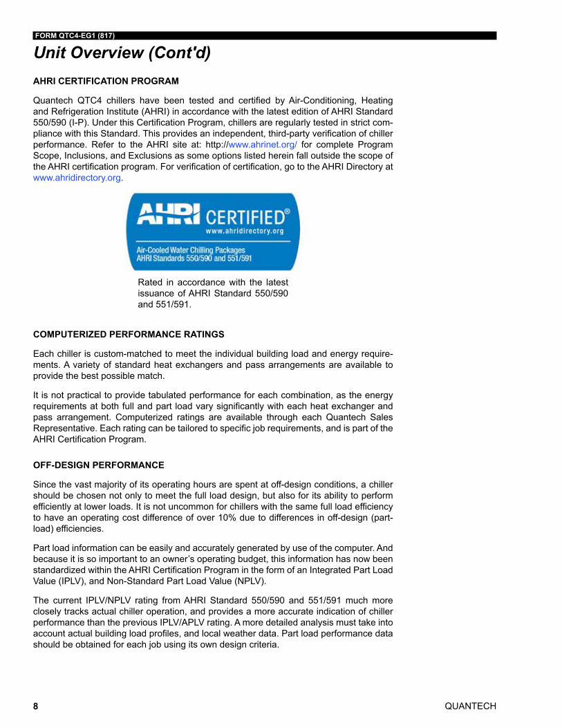
Quantech QTC4 chillers have been tested and certified by Air-Conditioning, Heating and Refrigeration Institute (AHRI) in accordance with the latest edition of AHRI Standard 550/590 (I-P). Under this Certification Program, chillers are regularly tested in strict com-pliance with this Standard. This provides an independent, third-party verification of chiller performance. Refer to the AHRI site at: http://www.ahrinet.org/ for complete Program Scope, Inclusions, and Exclusions as some options listed herein fall outside the scope of the AHRI certification program. For verification of certification, go to the AHRI Directory at www.ahridirectory.org.
Rated in accordance with the latest issuance of AHRI Standard 550/590 and 551/591.
COMPUTERIZED PERFORMANCE RATINGS
Each chiller is custom-matched to meet the individual building load and energy require-ments. A variety of standard heat exchangers and pass arrangements are available to provide the best possible match.
It is not practical to provide tabulated performance for each combination, as the energy requirements at both full and part load vary significantly with each heat exchanger and pass arrangement. Computerized ratings are available through each Quantech Sales Representative. Each rating can be tailored to specific job requirements, and is part of the AHRI Certification Program.
OFF-DESIGN PERFORMANCE
Since the vast majority of its operating hours are spent at off-design conditions, a chiller should be chosen not only to meet the full load design, but also for its ability to perform efficiently at lower loads. It is not uncommon for chillers with the same full load efficiency to have an operating cost difference of over 10% due to differences in off-design (part-load) efficiencies.
Part load information can be easily and accurately generated by use of the computer. And because it is so important to an owner’s operating budget, this information has now been standardized within the AHRI Certification Program in the form of an Integrated Part Load Value (IPLV), and Non-Standard Part Load Value (NPLV).
The current IPLV/NPLV rating from AHRI Standard 550/590 and 551/591 much more closely tracks actual chiller operation, and provides a more accurate indication of chiller performance than the previous IPLV/APLV rating. A more detailed analysis must take into account actual building load profiles, and local weather data. Part load performance data should be obtained for each job using its own design criteria.
Unit Overview (Cont'd)
FORM QTC4-EG1 (817)
QUANTECH 9
UNIT CONTROL CENTER
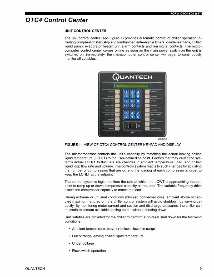
The unit control center (see Figure 1) provides automatic control of chiller operation in-cluding compressor start/stop and load/unload anti-recycle timers, condenser fans, chilled liquid pump, evaporator heater, unit alarm contacts and run signal contacts. The micro-computer control center comes online as soon as the main power switch on the unit is switched on; immediately, the microcomputer control center will begin to continuously monitor all variables.
FIGURE 1 - VIEW OF QTC4 CONTROL CENTER KEYPAD AND DISPLAY
LD21850
The microprocessor controls the unit’s capacity by matching the actual leaving chilled liquid temperature (LCHLT) to the user-defined setpoint. Factors that may cause the sys-tem’s actual LCHLT to fluctuate are changes in ambient temperature, load, and chilled liquid loop flow rate and volume. The controls system reacts to such changes by adjusting the number of compressors that are on and the loading of each compressor in order to keep the LCHLT at the setpoint.
The control system's logic monitors the rate at which the LCWT is approaching the set-point to ramp up or down compressor capacity as required. The variable frequency drive allows the compressor capacity to match the load.
During extreme or unusual conditions (blocked condenser coils, ambient above sched-uled maximum, and so on) the chiller control system will avoid shutdown by varying ca-pacity. By monitoring motor current and suction and discharge pressures, the chiller can maintain maximum available cooling output without shutting down.
Unit Safeties are provided for the chiller to perform auto-reset shut down for the following conditions:
• Ambient temperature above or below allowable range
• Out of range leaving chilled liquid temperature
• Under voltage
• Flow switch operation
QTC4 Control Center
QUANTECH
FORM QTC4-EG1 (817)
10
Display Data
• Leaving Chilled Liquid Temperature
• Returning Liquid Temperature
• Ambient Temperature
• Lead System
• Compressor Capacity (% of Full Load Amps)
• VSD Output Frequency / Compressor Speed
• Compressor Run Hours
• Compressor Number of Starts
• Oil Pressure and Temperature (per Compressor)
• Chilled Liquid Pump Status
• Evaporator Heater Status
• History Data for Last Twenty Normal Shutdowns
• History Data for Last Ten Shutdown Faults
Programmable Setpoints
• Chiller on/Off
• Chilled Liquid (Water or Glycol)
• Local or Remote Control
• Units of Measure (Imperial or SI)
• System Lead/Lag
• Remote Temperature Reset
• Remote Current Limit
• Leaving Chilled Liquid Temperature Setpoint and Range
QTC4 Control Center (Cont'd)
FORM QTC4-EG1 (817)
QUANTECH 11
All options factory mounted unless otherwise noted.
SOUND ATTENUATION
Low Noise Kits – The standard chiller configuration is equipped with low sound fans. There are several sound attenuation options available to further reduce sound at its source thereby meeting local sound level regulations.
SilentNight™ - Due to time-of-day based sound regulations in some locations, it may be desirable to force the chiller to a lower sound level on demand. The SilentNight control option provides a control input to limit sound output of the chiller based on time of day. This feature is programmable at the chiller panel or can be controlled remotely via a signal (4-20mA or 0-10 VDC) from a BAS system.
Ultra Quiet Fans – The chiller is equipped with specially designed fans and motors to pro-vide lower sound levels yet retain appropriate airflow. The result is reduced fan generated sound with minimal effect on the chiller capacity or efficiency at standard AHRI conditions. The fans are three-bladed for 60Hz and five-bladed for 50Hz.
CONDENSER COIL PROTECTION
The aluminum alloys used in the QTC4 microchannel condenser have been carefully selected and tested for high corrosion resistance. However, all metals can corrode in harsh conditions. Consider protecting coils from corrosive environments such as coastal, marine, urban and industrial.
Environment Guard Premium – Microchannel condenser coils coated with an elec-tro-deposited and baked flexible epoxy coating that is finished with a polyurethane UV resistant top-coat.
Environment Guard Basic – Microchannel condenser coils treated with immersion bath-applied chemical treatment.
Microchannel condenser with Environment Guard Premium or Basic shall be provided with a 5-year warranty against corrosion damage.
Accessories and Options
QUANTECH
FORM QTC4-EG1 (817)
12
PROTECTIVE CHILLER PANELS
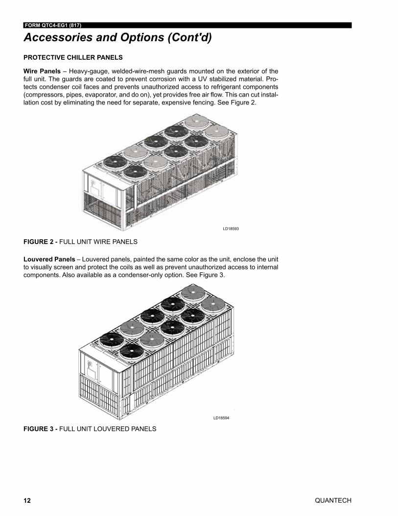
Wire Panels – Heavy-gauge, welded-wire-mesh guards mounted on the exterior of the full unit. The guards are coated to prevent corrosion with a UV stabilized material. Pro-tects condenser coil faces and prevents unauthorized access to refrigerant components (compressors, pipes, evaporator, and do on), yet provides free air flow. This can cut instal-lation cost by eliminating the need for separate, expensive fencing. See Figure 2.
FIGURE 2 - FULL UNIT WIRE PANELS
LD18593
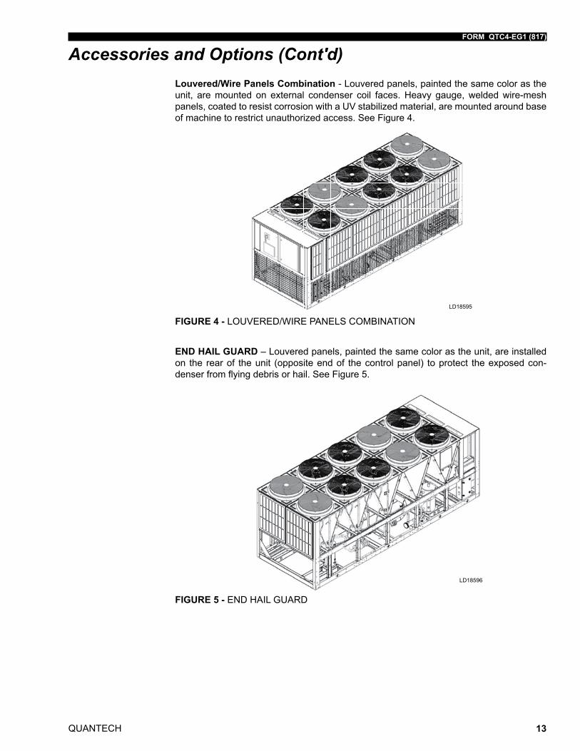
Louvered Panels – Louvered panels, painted the same color as the unit, enclose the unit to visually screen and protect the coils as well as prevent unauthorized access to internal components. Also available as a condenser-only option. See Figure 3.
FIGURE 3 - FULL UNIT LOUVERED PANELS
LD18594
Accessories and Options (Cont'd)
FORM QTC4-EG1 (817)
QUANTECH 13
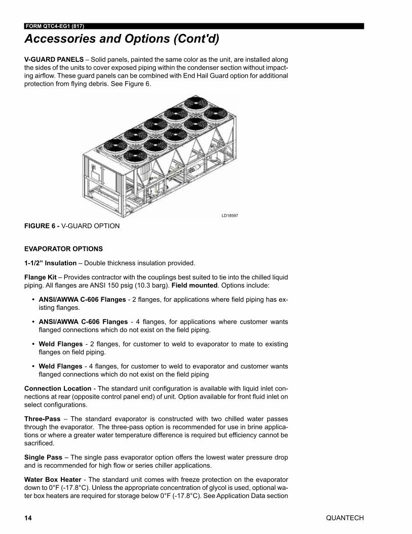
Louvered/Wire Panels Combination - Louvered panels, painted the same color as the unit, are mounted on external condenser coil faces. Heavy gauge, welded wire-mesh panels, coated to resist corrosion with a UV stabilized material, are mounted around base of machine to restrict unauthorized access. See Figure 4.
FIGURE 4 - LOUVERED/WIRE PANELS COMBINATION
LD18595
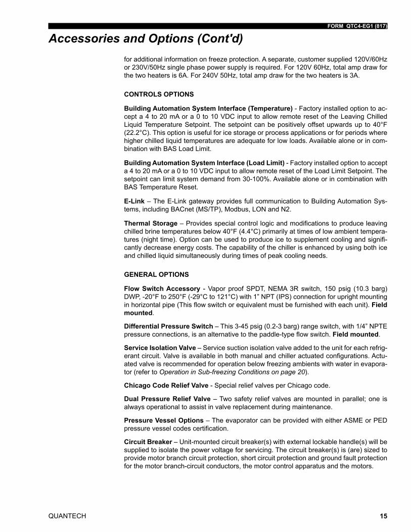
END HAIL GUARD – Louvered panels, painted the same color as the unit, are installed on the rear of the unit (opposite end of the control panel) to protect the exposed con-denser from flying debris or hail. See Figure 5.
FIGURE 5 - END HAIL GUARD
LD18596
Accessories and Options (Cont'd)
QUANTECH
FORM QTC4-EG1 (817)
14
V-GUARD PANELS – Solid panels, painted the same color as the unit, are installed along the sides of the units to cover exposed piping within the condenser section without impact-ing airflow. These guard panels can be combined with End Hail Guard option for additional protection from flying debris. See Figure 6.
FIGURE 6 - V-GUARD OPTIONLD18597
EVAPORATOR OPTIONS
1-1/2” Insulation – Double thickness insulation provided.
Flange Kit – Provides contractor with the couplings best suited to tie into the chilled liquid piping. All flanges are ANSI 150 psig (10.3 barg). Field mounted. Options include:
• ANSI/AWWA C-606 Flanges-2flanges,forapplicationswherefieldpipinghasex-istingflanges.
• ANSI/AWWA C-606 Flanges - 4 flanges, for applicationswhere customerwantsflangedconnectionswhichdonotexistonthefieldpiping.
• Weld Flanges -2flanges, forcustomer toweld toevaporator tomate toexistingflangesonfieldpiping.
• Weld Flanges-4flanges,forcustomertoweldtoevaporatorandcustomerwantsflangedconnectionswhichdonotexistonthefieldpiping
Connection Location - The standard unit configuration is available with liquid inlet con-nections at rear (opposite control panel end) of unit. Option available for front fluid inlet on select configurations.
Three-Pass – The standard evaporator is constructed with two chilled water passes through the evaporator. The three-pass option is recommended for use in brine applica-tions or where a greater water temperature difference is required but efficiency cannot be sacrificed.
Single Pass – The single pass evaporator option offers the lowest water pressure drop and is recommended for high flow or series chiller applications.
Water Box Heater - The standard unit comes with freeze protection on the evaporator down to 0°F (-17.8°C). Unless the appropriate concentration of glycol is used, optional wa-ter box heaters are required for storage below 0°F (-17.8°C). See Application Data section
Accessories and Options (Cont'd)
FORM QTC4-EG1 (817)
QUANTECH 15
Accessories and Options (Cont'd)for additional information on freeze protection. A separate, customer supplied 120V/60Hz or 230V/50Hz single phase power supply is required. For 120V 60Hz, total amp draw for the two heaters is 6A. For 240V 50Hz, total amp draw for the two heaters is 3A.
CONTROLS OPTIONS
Building Automation System Interface (Temperature) - Factory installed option to ac-cept a 4 to 20 mA or a 0 to 10 VDC input to allow remote reset of the Leaving Chilled Liquid Temperature Setpoint. The setpoint can be positively offset upwards up to 40°F (22.2°C). This option is useful for ice storage or process applications or for periods where higher chilled liquid temperatures are adequate for low loads. Available alone or in com-bination with BAS Load Limit.
Building Automation System Interface (Load Limit) - Factory installed option to accept a 4 to 20 mA or a 0 to 10 VDC input to allow remote reset of the Load Limit Setpoint. The setpoint can limit system demand from 30-100%. Available alone or in combination with BAS Temperature Reset.
E-Link – The E-Link gateway provides full communication to Building Automation Sys-tems, including BACnet (MS/TP), Modbus, LON and N2.
Thermal Storage – Provides special control logic and modifications to produce leaving chilled brine temperatures below 40°F (4.4°C) primarily at times of low ambient tempera-tures (night time). Option can be used to produce ice to supplement cooling and signifi-cantly decrease energy costs. The capability of the chiller is enhanced by using both ice and chilled liquid simultaneously during times of peak cooling needs.
GENERAL OPTIONS
Flow Switch Accessory - Vapor proof SPDT, NEMA 3R switch, 150 psig (10.3 barg) DWP, -20°F to 250°F (-29°C to 121°C) with 1” NPT (IPS) connection for upright mounting in horizontal pipe (This flow switch or equivalent must be furnished with each unit). Field mounted.
Differential Pressure Switch – This 3-45 psig (0.2-3 barg) range switch, with 1/4” NPTE pressure connections, is an alternative to the paddle-type flow switch. Field mounted.
Service Isolation Valve – Service suction isolation valve added to the unit for each refrig-erant circuit. Valve is available in both manual and chiller actuated configurations. Actu-ated valve is recommended for operation below freezing ambients with water in evapora-tor (refer to Operation in Sub-freezing Conditions on page 20).
Chicago Code Relief Valve - Special relief valves per Chicago code.
Dual Pressure Relief Valve – Two safety relief valves are mounted in parallel; one is always operational to assist in valve replacement during maintenance.
Pressure Vessel Options – The evaporator can be provided with either ASME or PED pressure vessel codes certification.
Circuit Breaker – Unit-mounted circuit breaker(s) with external lockable handle(s) will be supplied to isolate the power voltage for servicing. The circuit breaker(s) is (are) sized to provide motor branch circuit protection, short circuit protection and ground fault protection for the motor branch-circuit conductors, the motor control apparatus and the motors.
QUANTECH
FORM QTC4-EG1 (817)
16
Non-Fused Disconnect Switch – Unit-mounted disconnect switch(es) with external lock-able handle can be supplied to isolate the unit power voltage for servicing. Separate ex-ternal fusing must be supplied by the power wiring, which must comply with local codes.
Thermal Dispersion Flow Switch – Solid state thermal dispersion flow switch with no moving parts for high reliability and long service life. Stainless steel probe and IP 67 housing with LED status indicator of flow and output condition. Includes 10m IP67 cable required for field installation near chiller and bronzed steel welding adapter to ensure correct insertion depth. Field Mounted.
Special Requirement Documents – There are two options to select from:
• Special Requirement Document Package (SRDP) includes Pressure Vessel Report, Unit Run Test Report, Production System Check Sheet and Final Unit Inspection Check Sheet.
• Materials Package includes steel mill material reports for vessels in addition to the SRDP.
VIBRATION ISOLATION
Elastomeric Isolation – This option is recommended for normal installations. It provides very good performance in most applications for the least cost. Field mounted.
1” Spring Isolators – Spring and cage type isolators for mounting under the unit base rails are available to support unit. They are level adjustable. 1” nominal deflection may vary slightly by application. Field mounted.
2” Restrained Spring Isolators – Restrained Spring-Flex Mounting isolators incorporate a rugged welded steel housing with vertical and horizontal limit stops. Housings designed to withstand a minimum 1.0g accelerated force in all directions up to 2” (51mm). The de-flection may vary slightly by application. They are level adjustable. Field mounted.
Accessories and Options (Cont'd)
FORM QTC4-EG1 (817)
QUANTECH 17
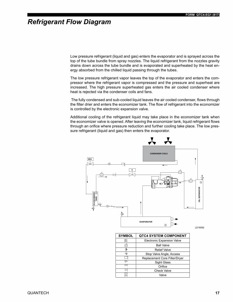
Low pressure refrigerant (liquid and gas) enters the evaporator and is sprayed across the top of the tube bundle from spray nozzles. The liquid refrigerant from the nozzles gravity drains down across the tube bundle and is evaporated and superheated by the heat en-ergy absorbed from the chilled liquid passing through the tubes.
The low pressure refrigerant vapor leaves the top of the evaporator and enters the com-pressor where the refrigerant vapor is compressed and the pressure and superheat are increased. The high pressure superheated gas enters the air cooled condenser where heat is rejected via the condenser coils and fans.
The fully condensed and sub-cooled liquid leaves the air cooled condenser, flows through the filter drier and enters the economizer tank. The flow of refrigerant into the economizer is controlled by the electronic expansion valve.
Additional cooling of the refrigerant liquid may take place in the economizer tank when the economizer valve is opened. After leaving the economizer tank, liquid refrigerant flows through an orifice where pressure reduction and further cooling take place. The low pres-sure refrigerant (liquid and gas) then enters the evaporator.
Refrigerant Flow Diagram
SYMBOL QTC4 SYSTEM COMPONENTElectronic Expansion Valve
Ball ValveRelief Valve
Stop Valve Angle, AccessReplacement Core Filter/Dryer
Sight GlassOrifice
Check ValveValve
LD18592
QUANTECH
FORM QTC4-EG1 (817)
18
Application Data
UNIT SIZING
Avoid over-sizing a chiller. Properly sized chillers operate stably and provide the best life cycle cost. When designing phased projects, select multiple small chillers to match de-mand for each phase. Use multiple small chillers when the minimum cooling demand is less than 10% of the maximum cooling demand.
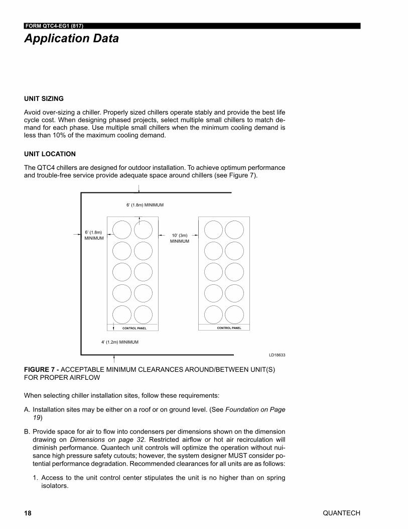
UNIT LOCATION
The QTC4 chillers are designed for outdoor installation. To achieve optimum performance and trouble-free service provide adequate space around chillers (see Figure 7).
LD18633
FIGURE 7 - ACCEPTABLE MINIMUM CLEARANCES AROUND/BETWEEN UNIT(S) FOR PROPER AIRFLOW
When selecting chiller installation sites, follow these requirements:
A. Installation sites may be either on a roof or on ground level. (See Foundation on Page 19)
B. Providespaceforairtoflowintocondensersperdimensionsshownonthedimensiondrawing on Dimensions on page 32. Restricted airflow or hot air recirculation willdiminish performance. Quantech unit controls will optimize the operation without nui-sance high pressure safety cutouts; however, the system designer MUST consider po-tential performance degradation. Recommended clearances for all units are as follows:
1. Access to the unit control center stipulates the unit is no higher than on spring isolators.
FORM QTC4-EG1 (817)
QUANTECH 19
2. Recommended minimum clearances:
a. Side to wall – 6’ (1.8m)
b. Rear to wall – 6’ (1.8m)
c. Control panel end to wall – 4’ (1.2m)
d. Top – no obstructions whatsoever
e. Distance between adjacent units – 10’ (3m)
3. No more than one wall around the chiller yard should be higher than the chiller(s)
C. Avoid locations near windows or structures where normal operating sounds may be objectionable.
D. The condenser fans are propeller-type and are not recommended for use with duct-work,filtersorotherimpedimentstoairflowinthecondenserairstream.
E. Whenobstructionstoairflowexist, theymustnotaddmorethan0.1”externalstaticpressure.
F. Protection against corrosive environments is available by ordering the units with cured epoxy-coating on the condenser microchannel. Epoxy-coated coils should be used with any units being installed at the seashore, or where salt spray may hit the units, or where acid rain is prevalent.
G. On installations where winter operation is intended and snow accumulations are ex-pected,additionalelevationmustbeprovidedtoinsurenormalcondenserairflow.
H. Provide adequate space for tubes to be removed from evaporator. For clearances please contact your nearest Quantech Sales Representative.
FOUNDATION
Mount units on a flat and level foundation, ground or roof, capable of supporting the entire operating weight of the equipment. Please contact your nearest Quantech Sales Repre-sentative for shipping and operating weights.
Roof Locations – Provide structure to safely support the entire weight of the unit and ser-vice personnel. Do not damage the roof during installation. If the roof is “bonded”, consult a building contractor or architect for special installation requirements. Use spring isolators to minimize vibration transmission into building structure. Provide additional structural support at the spring-isolator locations.
Ground Locations – Units must be installed on a substantial base that will not settle and cause strain on the refrigerant lines, resulting in possible leaks. A one-piece concrete slab, with footers extending below the frost line is recommended. The slab should not be tied to the main building foundation as operational noise will telegraph. Mounting holes (5/8”) are provided in the base rails for bolting the unit to its foundation. See Isolator Locations on Page 34 for location of the mounting holes.
For ground installations, precautions should be taken to protect the unit from tampering by, or injury to, unauthorized persons. Fasteners on access panels will prevent casual tampering; however, further safety precautions such as unit enclosure options, a fenced-in enclosure, or locking devices on the panels may be advisable. Check local authorities for safety regulations.
Application Data (Cont'd)
QUANTECH
FORM QTC4-EG1 (817)
20
Seismic Applications – Avoid installing chillers on springs or roofs where earthquakes are a risk. Springs and roofs amplify earthquake forces. Rigidly mounting chillers to ground level concrete pads is typically the best option for earthquake zones. Contact Quantech equipment specialists for help with projects that have seismic requirements.
CHILLED LIQUID PIPING
Design the chilled liquid piping system so that the circulating pump discharges into the evaporator. The inlet and outlet evaporator-liquid connections are given in Dimensions on Page 32. Hand stop valves are recommended in all lines to facilitate servicing. Provide drain connections at low points to permit complete drainage of the evaporator and system piping.
The evaporator must be protected by a strainer, preferably of 40 mesh, fitted as close as possible to the liquid inlet connection, and provided with a means of local isolation.
The evaporator must not be exposed to flushing velocities or debris released during flush-ing. It is recommended that a suitably sized bypass and valve arrangement is installed to allow flushing of the piping system. The bypass can be used during maintenance to isolate the heat exchanger without disrupting flow to other units.
Pressure-gauge connections are recommended for installation in the inlet and outlet liquid lines. Gauges are not provided with the unit and are to be furnished by others.
A flow switch is available as an accessory on all units. A flow switch must be installed in the leaving liquid piping of the evaporator and must not be used to start and stop the unit.
Chilled liquid lines exposed to the weather should be wrapped with a supplemental heater cable and insulated, or glycol should be added to the chilled liquid to protect against freez-ing if low-ambient periods are expected.
OPERATION IN SUB-FREEZING CONDITIONS
The QTC4 may be operated in sub-freezing conditions if the following freeze protections are taken :
A. An automatic suction service valve electric actuator is installed. Chiller software will operate the actuator in order to protect against freezing due to evaporator refrigerant migration.
-or-
B. No suction service valve is installed but the water circuit valves are kept open, there is continuous power to the chiller and pump for chilled water pump control, and the pump will operate and circulate water through the evaporator whenever commanded by the chiller.
Warning: The above operation is only advised if uninterrupted power can be ensured. Unforeseen power interruptions can damage the evaporator in a very short time frame if the temperature falls below freezing.
If there is potential for power loss, Quantech recommends the water in the chilled water circuit be replaced with an appropriate water-to-glycol concentration.
Application Data (Cont'd)
FORM QTC4-EG1 (817)
QUANTECH 21
UNIT MAINTENANCE AND SHUTDOWN IN SUB-FREEZING CONDITIONS
If the QTC4 is maintained or shut down and will be subjected to sub-freezing conditions, it is critical to protect against evaporator and waterbox freeze damage. Quantech recom-mends the following options (in order of freeze protection level) be performed on each circuit.
A. Glycol: Replace water with an appropriate water to glycol concentration of antifreeze.
-or-
B. Drain: Remove power to the waterbox heaters. Close the water valves, drain the evap-orator, and leave the evaporator drain valves open.
-or-
C. Refrigerant Valve - Off:Closethewatervalves,closeflashtankdrainvalves,closethe suction service valves and leave power to the chiller for evaporator heater mat and waterbox heater operation. For units without a suction service valve, close the discharge and compressor oil valves.
-or-
D. Pump Control: Keep power to the chiller in order to have control over chilled water pumps and heater operation and leave the water circuit valves open. This will enable water to circulate through the evaporator to avoid freezing.
Warning: Options A and B are the recommended processes for unit maintenance and shutdown. Unforeseen power interruptions can damage the evaporator in a very short time frame if the temperature falls below freezing.
Note: Failure to follow Quantech freeze protection recommendations can void the war-ranty.
MINIMUM LIQUID VOLUME
It is good practice to include as much liquid volume as possible in a chilled liquid loop. This increases the thermal mass and “Flywheel” effect within the system (that is, the more the better) which in turn promotes stable liquid temperature control and increases reliability by reducing compressor cycling.
For air conditioning applications, a minimum of 3 gallons/ton (3.2 liters/cooling kW) is recommended. It is preferred that the gallon/ton ratio be within the 5 to 8 (5.4 to 8.6 liter/cooling kW) range for constant flow rate chilled liquid systems. See Variable Primary Flow on page 23 for recommendations for VPF systems. For process applications, a mini-mum of 6 gallons/ton (6.5 liter/cooling kW) ratio is recommended with preference towards a range of 7 to 11 (7.5 to 11.8). Install a tank or increase pipe sizes to provide sufficient liquid volume.
LEAVING LIQUID TEMPERATURE OUT OF RANGE
The QTC4 chiller line has a maximum leaving liquid temperature of 60°F (15.6°F). Some process applications require a chilled liquid temperature higher than what the chiller pro-vides. In those applications, a simple piping change can remove the problem. By using a mixture of chiller-cooled liquid and returning process liquid, the chilled liquid entering the process can be held at the desired temperature. (A tank can also be used to meet high leaving liquid temperature requirements.) (See Figure 8 on page 22.)
Application Data (Cont'd)
QUANTECH
FORM QTC4-EG1 (817)
22
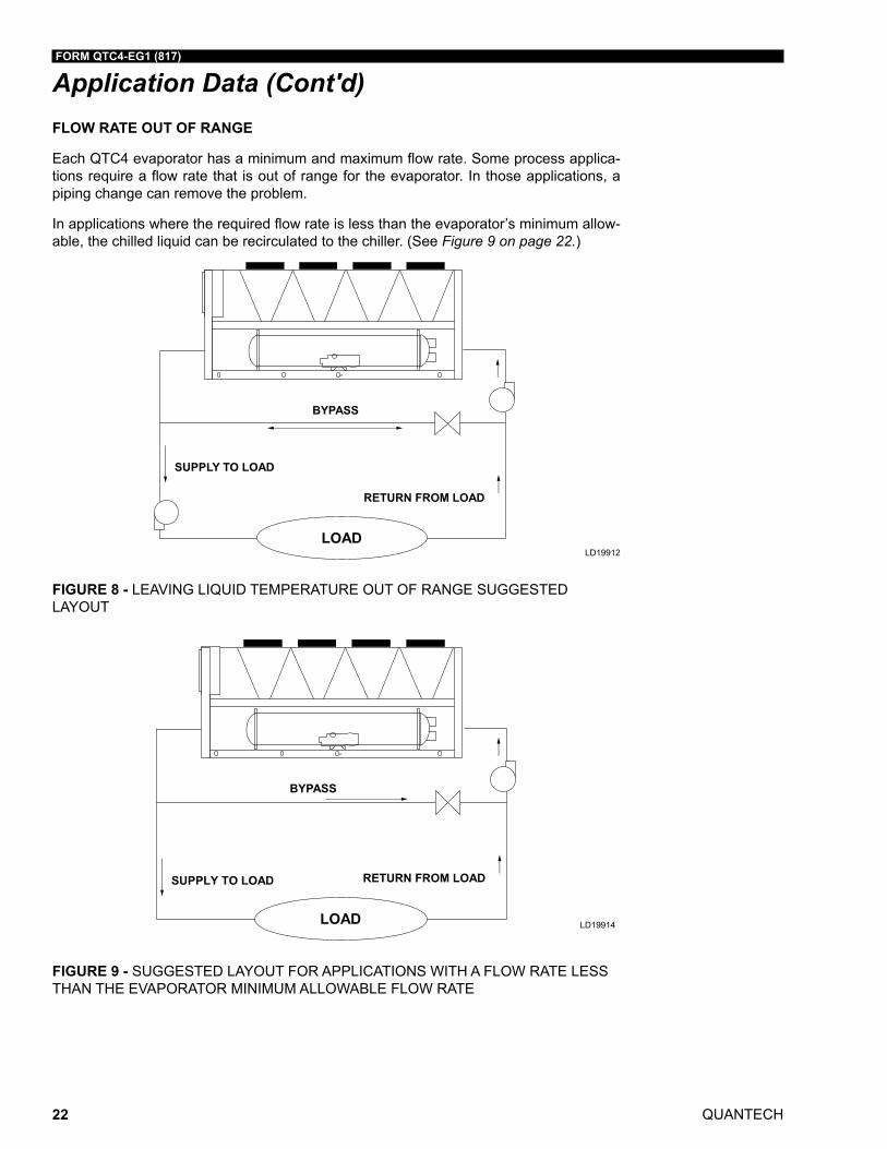
FLOW RATE OUT OF RANGE
Each QTC4 evaporator has a minimum and maximum flow rate. Some process applica-tions require a flow rate that is out of range for the evaporator. In those applications, a piping change can remove the problem.
In applications where the required flow rate is less than the evaporator’s minimum allow-able, the chilled liquid can be recirculated to the chiller. (See Figure 9 on page 22.)
FIGURE 8 - LEAVING LIQUID TEMPERATURE OUT OF RANGE SUGGESTED LAYOUT
LD19912
LD19914
FIGURE 9 - SUGGESTED LAYOUT FOR APPLICATIONS WITH A FLOW RATE LESS THAN THE EVAPORATOR MINIMUM ALLOWABLE FLOW RATE
Application Data (Cont'd)
FORM QTC4-EG1 (817)
QUANTECH 23
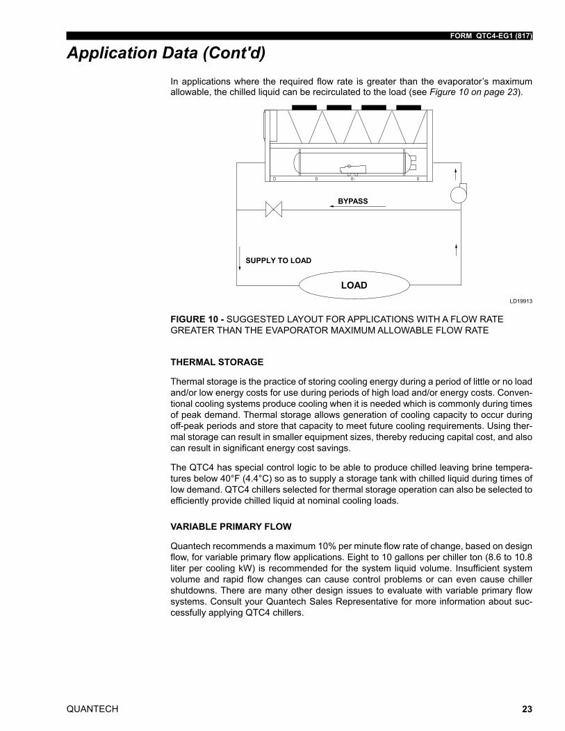
In applications where the required flow rate is greater than the evaporator’s maximum allowable, the chilled liquid can be recirculated to the load (see Figure 10 on page 23).
FIGURE 10 - SUGGESTED LAYOUT FOR APPLICATIONS WITH A FLOW RATE GREATER THAN THE EVAPORATOR MAXIMUM ALLOWABLE FLOW RATE
LD19913
THERMAL STORAGE
Thermal storage is the practice of storing cooling energy during a period of little or no load and/or low energy costs for use during periods of high load and/or energy costs. Conven-tional cooling systems produce cooling when it is needed which is commonly during times of peak demand. Thermal storage allows generation of cooling capacity to occur during off-peak periods and store that capacity to meet future cooling requirements. Using ther-mal storage can result in smaller equipment sizes, thereby reducing capital cost, and also can result in significant energy cost savings.
The QTC4 has special control logic to be able to produce chilled leaving brine tempera-tures below 40°F (4.4°C) so as to supply a storage tank with chilled liquid during times of low demand. QTC4 chillers selected for thermal storage operation can also be selected to efficiently provide chilled liquid at nominal cooling loads.
VARIABLE PRIMARY FLOW
Quantech recommends a maximum 10% per minute flow rate of change, based on design flow, for variable primary flow applications. Eight to 10 gallons per chiller ton (8.6 to 10.8 liter per cooling kW) is recommended for the system liquid volume. Insufficient system volume and rapid flow changes can cause control problems or can even cause chiller shutdowns. There are many other design issues to evaluate with variable primary flow systems. Consult your Quantech Sales Representative for more information about suc-cessfully applying QTC4 chillers.
Application Data (Cont'd)
QUANTECH
FORM QTC4-EG1 (817)
24
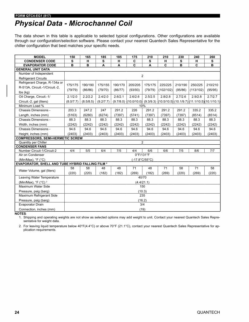
The data shown in this table is applicable to selected typical configurations. Other configurations are available through our configuration/selection software. Please contact your nearest Quantech Sales Representative for the chiller configuration that best matches your specific needs.
Physical Data - Microchannel Coil
NOTES:1. Shipping and operating weights are not show as selected options may add weight to unit. Contact your nearest Quantech Sales Repre-
sentative for weight data.2. For leaving liquid temperature below 40°F(4.4°C) or above 70°F (21.1°C), contact your nearest Quantech Sales Representative for ap-
plication requirements.
MODEL 150 165 185 185 175 210 210 230 240 260 MODEL 270 270 270 290 300 300 320 330 340 340 370CONDENSER CODE S H S H C S H S H S CONDENSER CODE C S H H S H S S S H SEVAPORATOR CODE B B A A C A C B C B EVAPORATOR CODE D D E E C C E C E E F
GENERAL UNIT DATA GENERAL UNIT DATANumber of Independent Refrigerant Circuits
2Number of Independent Refrigerant Circuits
2
Refrigerant Charge, R-134a or R-513A, Circuit.-1/Circuit.-2, lbs (kg)
175/175 (79/79)
190/190 (86/86)
175/155 (79/70)
190/170 (86/77)
205/205 (93/93)
175/175 (79/79)
225/225 (102/102)
210/190 (95/86)
250/225 (113/102)
210/210 (95/95)
Refrigerant Charge, R-134a, R-513A, Circuit.-1/Circuit.-2, lbs (kg)
250/250 (114/114)
265/265 (120/120)
265/265 (120/120)
310/265 (141/120)
290/245 (132/111)
295/250(134/114)
295/295(134/134)
290/290(132/132)
310/310(141/141)
315/315(143/143)
420/245(191/111)
Oil Charge, Circuit.-1/ Circuit.-2, gal (liters)
2.1/2.0 (8.0/7.7)
2.2/2.2 (8.5/8.5)
2.4/2.0 (9.2/7.7)
2.6/2.1 (9.7/8.0)
2.6/2.6 (10.0/10.0)
2.5/2.5 (9.3/9.3)
2.8/2.8 (10.5/10.5)
2.7/2.6 (10.1/9.7)
2.9/2.8 (11.1/10.5)
2.7/2.7 (10.1/10.1)
Oil Charge, Circuit.-1/Circuit.-2, gal (liters)
3.0/3.0 (11.4/11.4)
3.0/3.0 (11.4/11.4)
3.0/3.0 (11.4/11.4)
4.2/3.1 (15.9/11.7)
4.1/3.0 (15.5/11.4)
4.1/3.0(15.5/11.4)
4.1/4.1(15.5/15.5)
4.1/4.1(15.5/15.5)
4.2/4.2(15.9/15.9)
4.3/4.3(16.3/16.3)
5.3/2.9(20.1/11.0)
Minimum Load % 10% Minimum Load % 10%Chassis Dimensions - Length, inches (mm)
203.3 (5163)
247.2 (6280)
247 (6274)
291.2 (7397)
226 (5741)
291.2 (7397)
291.2 (7397)
291.2 (7397)
335.2 (8514)
335.2 (8514)
Chassis Dimensions - Length, inches (mm)
291.2 (7397)
335.2 (8514)
335.2 (8514)
379.2 (9631)
379.2 (9631)
423.1(10748)
379.2(9631)
423.1(10748)
423.1(10748)
467.1(11865)
467.1(11864)
Chassis Dimensions - Width, inches (mm)
88.3 (2242)
88.3 (2242)
88.3 (2242)
88.3 (2242)
88.3 (2242)
88.3 (2242)
88.3 (2242)
88.3 (2242)
88.3 (2242)
88.3 (2242)
Chassis Dimensions - Width, inches (mm)
88.3 (2242)
88.3 (2242)
88.3 (2242)
88.3 (2242)
88.3 (2242)
88.3(2242)
88.3(2242)
88.3(2242)
88.3(2242)
88.3(2242)
88.3(2243)
Chassis Dimensions - Height, inches (mm)
94.6 (2403)
94.6 (2403)
94.6 (2403)
94.6 (2403)
94.6 (2403)
94.6 (2403)
94.6 (2403)
94.6 (2403)
94.6 (2403)
94.6 (2403)
Chassis Dimensions - Height, inches (mm)
94.6 (2403)
94.6 (2403)
94.6 (2403)
94.6 (2403)
94.6 (2403)
94.6(2403)
94.6(2403)
94.6(2403)
94.6(2403)
94.6(2403)
94.7(2405)
COMPRESSORS, SEMI-HERMETIC SCREW COMPRESSORS, SEMI-HERMETIC SCREWQuantity per Chiller 2 Quantity per Chiller 2
CONDENSER FANS CONDENSER FANSNumber Circuit-1/Circuit-2 4/4 5/5 6/4 7/5 4/4 6/6 6/6 7/5 8/6 7/7 Number Circuit-1/Circuit-2 6/6 7/7 7/7 9/7 9/7 10/8 8/8 9/9 9/9 10/10 13/7Air on Condenser (Min/Max), °F (°C)
0°F/131°F (-17.8°C/55°C)
Air on Condenser (Min/Max), °F (°C)
0°F/131°F (-17.8°C/55°C)
EVAPORATOR, SHELL AND TUBE HYBRID FALLING FILM 2 EVAPORATOR, SHELL AND TUBE HYBRID FALLING FILM 2
Water Volume, gal (liters)58
(220)58
(220)48
(182)48
(182)71
(269)48
(182)71
(269)58
(220)71
(269)58
(220)Water Volume, gal (liters)
82 (310)
82 (310)
113 (428)
113 (428)
71 (269)
71(269)
113(428)
71(269)
113(428)
113(428)
96(363)
Leaving Water Temperature (Min/Max), °F (°C) 2
40/70 (4.4/21.1)
Leaving Water Temperature (Min/Max), °F (°C) 2
40/70 (4.4/21.1)
Maximum Water Side Pressure, psig (barg)
150 (10.3)
Maximum Water Side Pressure, psig (barg)
150 (10.3)
Maximum Refrigerant Side Pressure, psig (barg)
235 (16.2)
Maximum Refrigerant Side Pressure, psig (barg)
235 (16.2)
Evaporator Drain Connection, inches (mm)
3/4 (19)
Evaporator Drain Connection, inches (mm)
3/4 (19)
FORM QTC4-EG1 (817)
QUANTECH 25
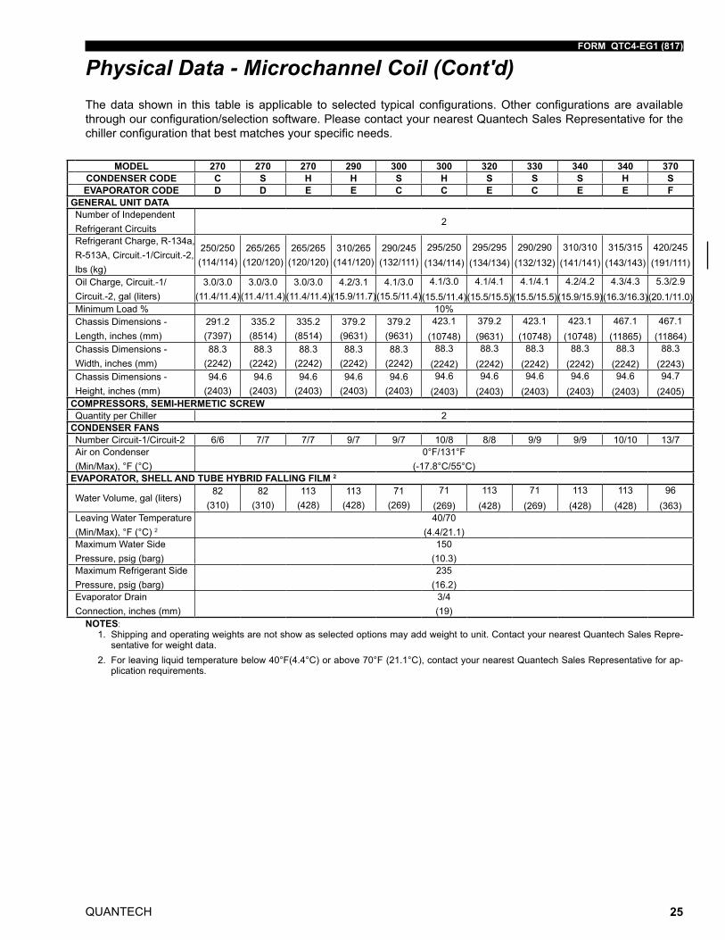
The data shown in this table is applicable to selected typical configurations. Other configurations are available through our configuration/selection software. Please contact your nearest Quantech Sales Representative for the chiller configuration that best matches your specific needs.
NOTES:1. Shipping and operating weights are not show as selected options may add weight to unit. Contact your nearest Quantech Sales Repre-
sentative for weight data. 2. For leaving liquid temperature below 40°F(4.4°C) or above 70°F (21.1°C), contact your nearest Quantech Sales Representative for ap-
plication requirements.
Physical Data - Microchannel Coil (Cont'd)
MODEL 150 165 185 185 175 210 210 230 240 260 MODEL 270 270 270 290 300 300 320 330 340 340 370CONDENSER CODE S H S H C S H S H S CONDENSER CODE C S H H S H S S S H SEVAPORATOR CODE B B A A C A C B C B EVAPORATOR CODE D D E E C C E C E E F
GENERAL UNIT DATA GENERAL UNIT DATANumber of Independent Refrigerant Circuits
2Number of Independent Refrigerant Circuits
2
Refrigerant Charge, R-134a or R-513A, Circuit.-1/Circuit.-2, lbs (kg)
175/175 (79/79)
190/190 (86/86)
175/155 (79/70)
190/170 (86/77)
205/205 (93/93)
175/175 (79/79)
225/225 (102/102)
210/190 (95/86)
250/225 (113/102)
210/210 (95/95)
Refrigerant Charge, R-134a, R-513A, Circuit.-1/Circuit.-2, lbs (kg)
250/250 (114/114)
265/265 (120/120)
265/265 (120/120)
310/265 (141/120)
290/245 (132/111)
295/250(134/114)
295/295(134/134)
290/290(132/132)
310/310(141/141)
315/315(143/143)
420/245(191/111)
Oil Charge, Circuit.-1/ Circuit.-2, gal (liters)
2.1/2.0 (8.0/7.7)
2.2/2.2 (8.5/8.5)
2.4/2.0 (9.2/7.7)
2.6/2.1 (9.7/8.0)
2.6/2.6 (10.0/10.0)
2.5/2.5 (9.3/9.3)
2.8/2.8 (10.5/10.5)
2.7/2.6 (10.1/9.7)
2.9/2.8 (11.1/10.5)
2.7/2.7 (10.1/10.1)
Oil Charge, Circuit.-1/Circuit.-2, gal (liters)
3.0/3.0 (11.4/11.4)
3.0/3.0 (11.4/11.4)
3.0/3.0 (11.4/11.4)
4.2/3.1 (15.9/11.7)
4.1/3.0 (15.5/11.4)
4.1/3.0(15.5/11.4)
4.1/4.1(15.5/15.5)
4.1/4.1(15.5/15.5)
4.2/4.2(15.9/15.9)
4.3/4.3(16.3/16.3)
5.3/2.9(20.1/11.0)
Minimum Load % 10% Minimum Load % 10%Chassis Dimensions - Length, inches (mm)
203.3 (5163)
247.2 (6280)
247 (6274)
291.2 (7397)
226 (5741)
291.2 (7397)
291.2 (7397)
291.2 (7397)
335.2 (8514)
335.2 (8514)
Chassis Dimensions - Length, inches (mm)
291.2 (7397)
335.2 (8514)
335.2 (8514)
379.2 (9631)
379.2 (9631)
423.1(10748)
379.2(9631)
423.1(10748)
423.1(10748)
467.1(11865)
467.1(11864)
Chassis Dimensions - Width, inches (mm)
88.3 (2242)
88.3 (2242)
88.3 (2242)
88.3 (2242)
88.3 (2242)
88.3 (2242)
88.3 (2242)
88.3 (2242)
88.3 (2242)
88.3 (2242)
Chassis Dimensions - Width, inches (mm)
88.3 (2242)
88.3 (2242)
88.3 (2242)
88.3 (2242)
88.3 (2242)
88.3(2242)
88.3(2242)
88.3(2242)
88.3(2242)
88.3(2242)
88.3(2243)
Chassis Dimensions - Height, inches (mm)
94.6 (2403)
94.6 (2403)
94.6 (2403)
94.6 (2403)
94.6 (2403)
94.6 (2403)
94.6 (2403)
94.6 (2403)
94.6 (2403)
94.6 (2403)
Chassis Dimensions - Height, inches (mm)
94.6 (2403)
94.6 (2403)
94.6 (2403)
94.6 (2403)
94.6 (2403)
94.6(2403)
94.6(2403)
94.6(2403)
94.6(2403)
94.6(2403)
94.7(2405)
COMPRESSORS, SEMI-HERMETIC SCREW COMPRESSORS, SEMI-HERMETIC SCREWQuantity per Chiller 2 Quantity per Chiller 2
CONDENSER FANS CONDENSER FANSNumber Circuit-1/Circuit-2 4/4 5/5 6/4 7/5 4/4 6/6 6/6 7/5 8/6 7/7 Number Circuit-1/Circuit-2 6/6 7/7 7/7 9/7 9/7 10/8 8/8 9/9 9/9 10/10 13/7Air on Condenser (Min/Max), °F (°C)
0°F/131°F (-17.8°C/55°C)
Air on Condenser (Min/Max), °F (°C)
0°F/131°F (-17.8°C/55°C)
EVAPORATOR, SHELL AND TUBE HYBRID FALLING FILM 2 EVAPORATOR, SHELL AND TUBE HYBRID FALLING FILM 2
Water Volume, gal (liters)58
(220)58
(220)48
(182)48
(182)71
(269)48
(182)71
(269)58
(220)71
(269)58
(220)Water Volume, gal (liters)
82 (310)
82 (310)
113 (428)
113 (428)
71 (269)
71(269)
113(428)
71(269)
113(428)
113(428)
96(363)
Leaving Water Temperature (Min/Max), °F (°C) 2
40/70 (4.4/21.1)
Leaving Water Temperature (Min/Max), °F (°C) 2
40/70 (4.4/21.1)
Maximum Water Side Pressure, psig (barg)
150 (10.3)
Maximum Water Side Pressure, psig (barg)
150 (10.3)
Maximum Refrigerant Side Pressure, psig (barg)
235 (16.2)
Maximum Refrigerant Side Pressure, psig (barg)
235 (16.2)
Evaporator Drain Connection, inches (mm)
3/4 (19)
Evaporator Drain Connection, inches (mm)
3/4 (19)
QUANTECH
FORM QTC4-EG1 (817)
26
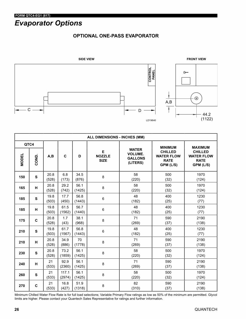
Evaporator OptionsOPTIONAL ONE-PASS EVAPORATOR
ALL DIMENSIONS - INCHES (MM)
QTC4
A,B C DE
NOZZLE SIZE
WATER VOLUME.
GALLONS (LITERS)
MINIMUM CHILLED
WATER FLOW RATE
GPM (L/S)
MAXIMUM CHILLED
WATER FLOW RATE
GPM (L/S)MO
DEL
CO
ND
.
150 S 20.8 (528)
6.8 (173)
34.5 (876)
8 58
(220)500 (32)
1970 (124)
165 H 20.8 (528)
29.2 (742)
56.1 (1425)
858
(220)500 (32)
1970 (124)
185 S 19.8 (503)
17.7 (450)
56.8 (1443)
648
(182)400 (25)
1230 (77)
185 H 19.8 (503)
61.5 (1562)
56.7 (1440)
648
(182)400 (25)
1230 (77)
175 C 20.8 (528)
1.7 (43)
38.1 (968)
871
(269)590 (37)
2190 (138)
210 S 19.8 (503)
61.7 (1567)
56.8 (1443)
648
(182)400 (25)
1230 (77)
210 H 20.8 (528)
34.9 (886)
70 (1778)
871
(269)590 (37)
2190 (138)
230 S 20.8 (528)
73.2 (1859)
56.1 (1425)
858
(220)500 (32)
1970 (124)
240 H 21 (533)
92.9 (2360)
56.1 (1425)
871
(269)590 (37)
2190 (138)
260 S 21 (533)
117.1 (2974)
56.1 (1425)
858
(220)500 (32)
1970 (124)
270 C 21 (533)
16.8 (427)
51.9 (1318)
882
(310)590 (37)
2190 (138)
Minimum Chilled Water Flow Rate is for full load selections; Variable Primary Flow ratings as low as 50% of the minimum are permitted. Glycol limits are higher. Please contact your Quantech Sales Representative for ratings and further information.
FORM QTC4-EG1 (817)
QUANTECH 27
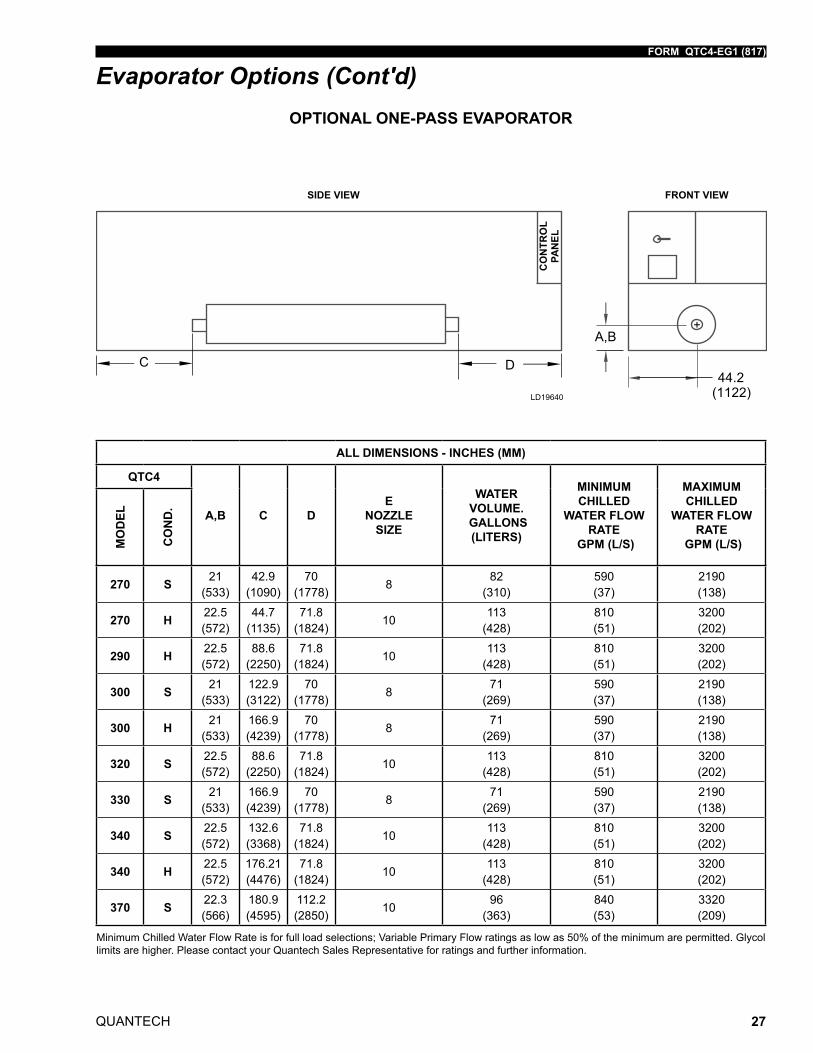
Evaporator Options (Cont'd)OPTIONAL ONE-PASS EVAPORATOR
ALL DIMENSIONS - INCHES (MM)
QTC4
A,B C DE
NOZZLE SIZE
WATER VOLUME.
GALLONS (LITERS)
MINIMUM CHILLED
WATER FLOW RATE
GPM (L/S)
MAXIMUM CHILLED
WATER FLOW RATE
GPM (L/S)MO
DEL
CO
ND
.
270 S 21 (533)
42.9 (1090)
70 (1778)
882
(310)590 (37)
2190 (138)
270 H 22.5 (572)
44.7 (1135)
71.8 (1824)
10113
(428)810 (51)
3200 (202)
290 H 22.5 (572)
88.6 (2250)
71.8 (1824)
10113
(428)810 (51)
3200 (202)
300 S 21 (533)
122.9 (3122)
70 (1778)
871
(269)590 (37)
2190 (138)
300 H 21 (533)
166.9 (4239)
70 (1778)
871
(269)590 (37)
2190 (138)
320 S 22.5 (572)
88.6 (2250)
71.8 (1824)
10113
(428)810 (51)
3200 (202)
330 S 21 (533)
166.9 (4239)
70 (1778)
871
(269)590 (37)
2190 (138)
340 S 22.5 (572)
132.6 (3368)
71.8 (1824)
10113
(428)810 (51)
3200 (202)
340 H 22.5 (572)
176.21 (4476)
71.8 (1824)
10113
(428)810 (51)
3200 (202)
370 S 22.3 (566)
180.9 (4595)
112.2 (2850)
1096
(363)840 (53)
3320 (209)
Minimum Chilled Water Flow Rate is for full load selections; Variable Primary Flow ratings as low as 50% of the minimum are permitted. Glycol limits are higher. Please contact your Quantech Sales Representative for ratings and further information.
QUANTECH
FORM QTC4-EG1 (817)
28
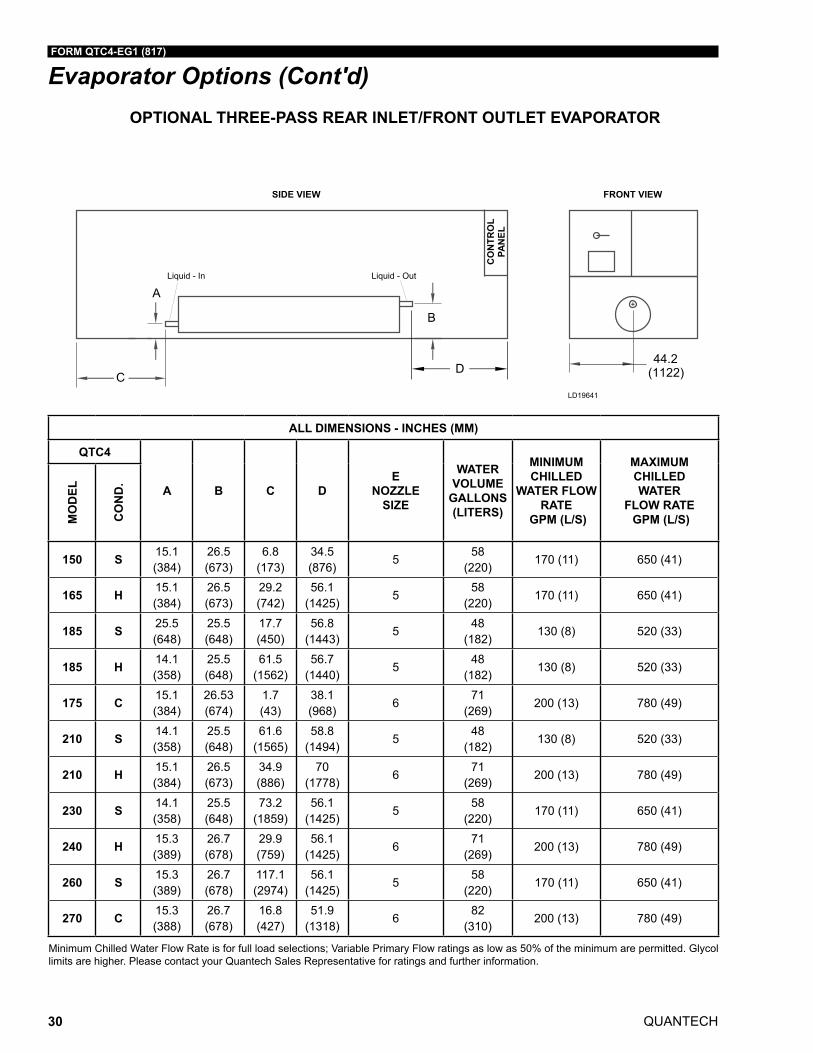
ALL DIMENSIONS - INCHES (MM)
QTC4
A B C DE
NOZZLE SIZE
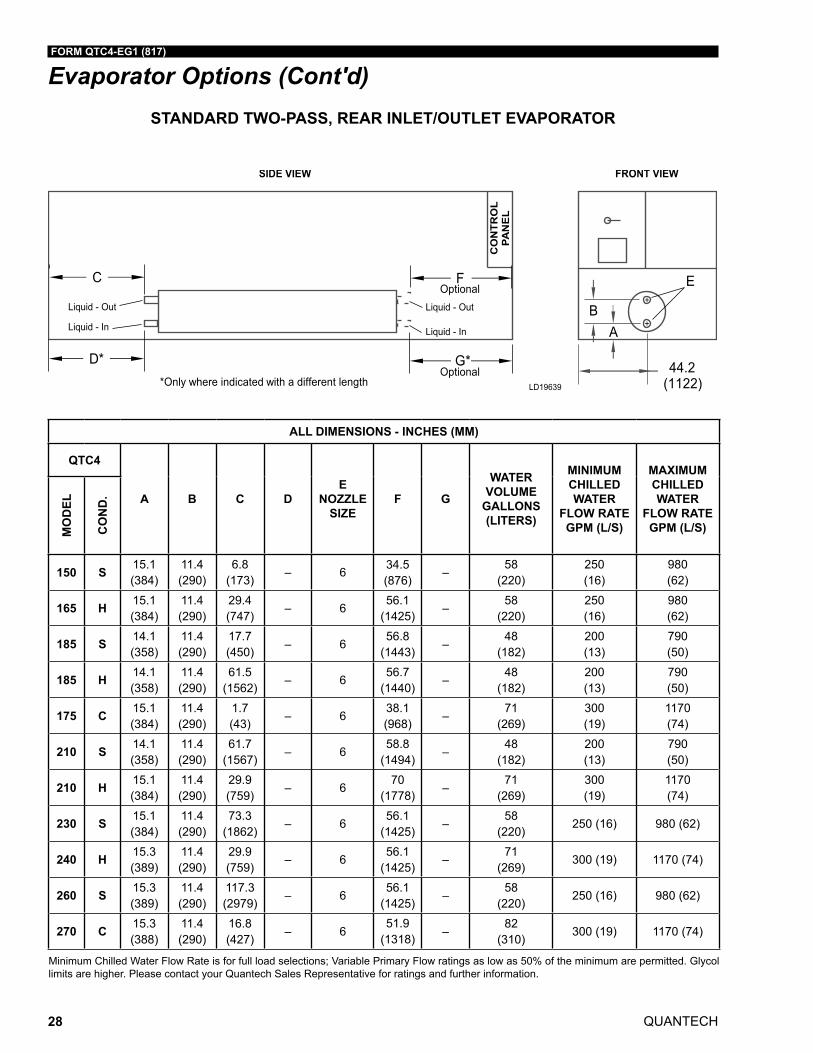
F G
WATER VOLUME
GALLONS (LITERS)
MINIMUM CHILLED WATER
FLOW RATE GPM (L/S)
MAXIMUM CHILLED WATER
FLOW RATE GPM (L/S)M
OD
EL
CO
ND
.
150 S 15.1 (384)
11.4 (290)
6.8 (173)
– 6 34.5 (876)
–58
(220)250 (16)
980 (62)
165 H 15.1 (384)
11.4 (290)
29.4 (747)
– 656.1
(1425)–
58 (220)
250 (16)
980 (62)
185 S 14.1 (358)
11.4 (290)
17.7 (450)
– 656.8
(1443)–
48 (182)
200 (13)
790 (50)
185 H 14.1 (358)
11.4 (290)
61.5 (1562)
– 656.7
(1440)–
48 (182)
200 (13)
790 (50)
175 C 15.1 (384)
11.4 (290)
1.7 (43)
– 638.1 (968)
–71
(269)300 (19)
1170 (74)
210 S 14.1 (358)
11.4 (290)
61.7 (1567)
– 658.8
(1494)–
48 (182)
200 (13)
790 (50)
210 H 15.1 (384)
11.4 (290)
29.9 (759)
– 670
(1778)–
71 (269)
300 (19)
1170 (74)
230 S 15.1 (384)
11.4 (290)
73.3 (1862)
– 656.1
(1425)–
58 (220)
250 (16) 980 (62)
240 H 15.3 (389)
11.4 (290)
29.9 (759)
– 656.1
(1425)–
71 (269)
300 (19) 1170 (74)
260 S 15.3 (389)
11.4 (290)
117.3 (2979)
– 656.1
(1425)–
58 (220)
250 (16) 980 (62)
270 C 15.3 (388)
11.4 (290)
16.8 (427)
– 651.9
(1318) –82
(310)300 (19) 1170 (74)
Minimum Chilled Water Flow Rate is for full load selections; Variable Primary Flow ratings as low as 50% of the minimum are permitted. Glycol limits are higher. Please contact your Quantech Sales Representative for ratings and further information.
STANDARD TWO-PASS, REAR INLET/OUTLET EVAPORATOR
Evaporator Options (Cont'd)
FORM QTC4-EG1 (817)
QUANTECH 29
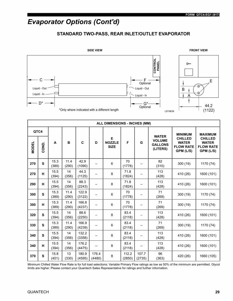
Evaporator Options (Cont'd)
ALL DIMENSIONS - INCHES (MM)
QTC4
A B C DE
NOZZLE SIZE
F G
WATER VOLUME
GALLONS (LITERS)
MINIMUM CHILLED WATER
FLOW RATE GPM (L/S)
MAXIMUM CHILLED WATER
FLOW RATE GPM (L/S)M
OD
EL
CO
ND
.
270 S 15.3 (389)
11.4 (290)
42.9 (1090)
– 6 70 (1778)
–82
(310)300 (19) 1170 (74)
270 H 15.5 (394)
14 (356)
44.3 (1125)
– 871.8
(1824)–
113 (428)
410 (26) 1600 (101)
290 H 15.5 (394)
14 (356)
88.3 (2243)
– 871.8
(1824)–
113 (428)
410 (26) 1600 (101)
300 S 15.3 (389)
11.4 (290)
122.9 (3122)
– 670
(1778)–
71 (269)
300 (19) 1170 (74)
300 H 15.3 (389)
11.4 (290)
166.8 (4237)
– 670
(1778)–
71 (269)
300 (19) 1170 (74)
320 S 15.5 (394)
14 (356)
88.6 (2250)
– 883.4
(2118)–
113 (428)
410 (26) 1600 (101)
330 S 15.3 (389)
11.4 (290)
166.9 (4239)
– 683.4
(2118)–
71 (269)
300 (19) 1170 (74)
340 S 15.5 (394)
14 (356)
132.2 (3358)
– 883.4
(2118)–
113 (428)
410 (26) 1600 (101)
340 H 15.5 (394)
14 (356)
176.2 (4475)
– 883.4
(2118)–
113 (428)
410 (26) 1600 (101)
370 S 15.8 (401)
13 (330)
180.9 (4595)
176.4 (4480)
8112.2 (2850)
107.7 (2735)
96 (363)
420 (26) 1660 (105)
Minimum Chilled Water Flow Rate is for full load selections; Variable Primary Flow ratings as low as 50% of the minimum are permitted. Glycol limits are higher. Please contact your Quantech Sales Representative for ratings and further information.
STANDARD TWO-PASS, REAR INLET/OUTLET EVAPORATOR
QUANTECH
FORM QTC4-EG1 (817)
30
Evaporator Options (Cont'd)
ALL DIMENSIONS - INCHES (MM)
QTC4
A B C DE
NOZZLE SIZE
WATER VOLUME
GALLONS (LITERS)
MINIMUM CHILLED
WATER FLOW RATE
GPM (L/S)
MAXIMUM CHILLED WATER
FLOW RATE GPM (L/S)M
OD
EL
CO
ND
.
150 S 15.1 (384)
26.5 (673)
6.8 (173)
34.5 (876)
5 58
(220)170 (11) 650 (41)
165 H 15.1 (384)
26.5 (673)
29.2 (742)
56.1 (1425)
558
(220)170 (11) 650 (41)
185 S 25.5 (648)
25.5 (648)
17.7 (450)
56.8 (1443)
548
(182)130 (8) 520 (33)
185 H 14.1 (358)
25.5 (648)
61.5 (1562)
56.7 (1440)
548
(182)130 (8) 520 (33)
175 C 15.1 (384)
26.53 (674)
1.7 (43)
38.1 (968)
671
(269)200 (13) 780 (49)
210 S 14.1 (358)
25.5 (648)
61.6 (1565)
58.8 (1494)
548
(182)130 (8) 520 (33)
210 H 15.1 (384)
26.5 (673)
34.9 (886)
70 (1778)
671
(269)200 (13) 780 (49)
230 S 14.1 (358)
25.5 (648)
73.2 (1859)
56.1 (1425)
558
(220)170 (11) 650 (41)
240 H 15.3 (389)
26.7 (678)
29.9 (759)
56.1 (1425)
671
(269)200 (13) 780 (49)
260 S 15.3 (389)
26.7 (678)
117.1 (2974)
56.1 (1425)
558
(220)170 (11) 650 (41)
270 C 15.3 (388)
26.7 (678)
16.8 (427)
51.9 (1318)
682
(310)200 (13) 780 (49)
Minimum Chilled Water Flow Rate is for full load selections; Variable Primary Flow ratings as low as 50% of the minimum are permitted. Glycol limits are higher. Please contact your Quantech Sales Representative for ratings and further information.
OPTIONAL THREE-PASS REAR INLET/FRONT OUTLET EVAPORATOR
FORM QTC4-EG1 (817)
QUANTECH 31
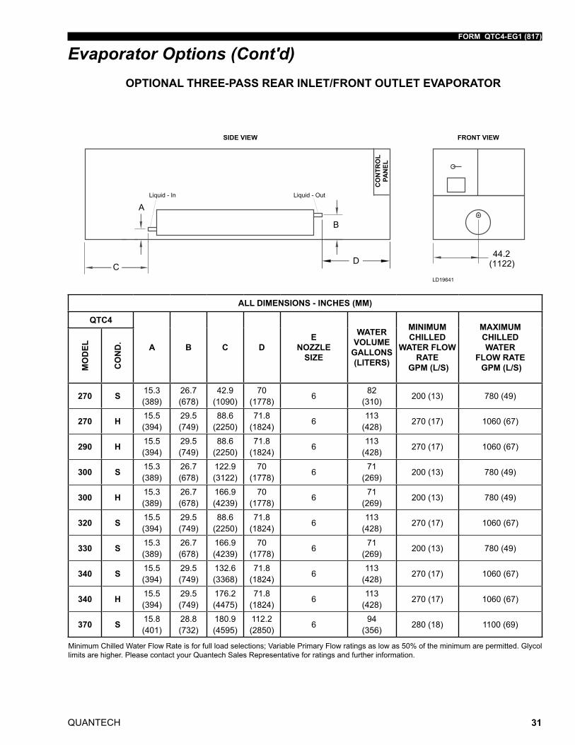
OPTIONAL THREE-PASS REAR INLET/FRONT OUTLET EVAPORATOR
Evaporator Options (Cont'd)
ALL DIMENSIONS - INCHES (MM)
QTC4
A B C DE
NOZZLE SIZE
WATER VOLUME
GALLONS (LITERS)
MINIMUM CHILLED
WATER FLOW RATE
GPM (L/S)
MAXIMUM CHILLED WATER
FLOW RATE GPM (L/S)M
OD
EL
CO
ND
.
270 S 15.3 (389)
26.7 (678)
42.9 (1090)
70 (1778)
682
(310)200 (13) 780 (49)
270 H 15.5 (394)
29.5 (749)
88.6 (2250)
71.8 (1824)
6113
(428)270 (17) 1060 (67)
290 H 15.5 (394)
29.5 (749)
88.6 (2250)
71.8 (1824)
6113
(428)270 (17) 1060 (67)
300 S 15.3 (389)
26.7 (678)
122.9 (3122)
70 (1778)
671
(269)200 (13) 780 (49)
300 H 15.3 (389)
26.7 (678)
166.9 (4239)
70 (1778)
671
(269)200 (13) 780 (49)
320 S 15.5 (394)
29.5 (749)
88.6 (2250)
71.8 (1824)
6113
(428)270 (17) 1060 (67)
330 S 15.3 (389)
26.7 (678)
166.9 (4239)
70 (1778)
671
(269)200 (13) 780 (49)
340 S 15.5 (394)
29.5 (749)
132.6 (3368)
71.8 (1824)
6113
(428)270 (17) 1060 (67)
340 H 15.5 (394)
29.5 (749)
176.2 (4475)
71.8 (1824)
6113
(428)270 (17) 1060 (67)
370 S 15.8 (401)
28.8 (732)
180.9 (4595)
112.2 (2850)
694
(356)280 (18) 1100 (69)
Minimum Chilled Water Flow Rate is for full load selections; Variable Primary Flow ratings as low as 50% of the minimum are permitted. Glycol limits are higher. Please contact your Quantech Sales Representative for ratings and further information.
QUANTECH
FORM QTC4-EG1 (817)
32
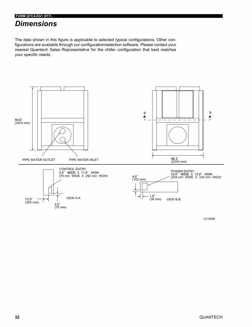
Dimensions
The data shown in this figure is applicable to selected typical configurations. Other con-figurations are available through our configuration/selection software. Please contact your nearest Quantech Sales Representative for the chiller configuration that best matches your specific needs.
LD18586
FORM QTC4-EG1 (817)
QUANTECH 33
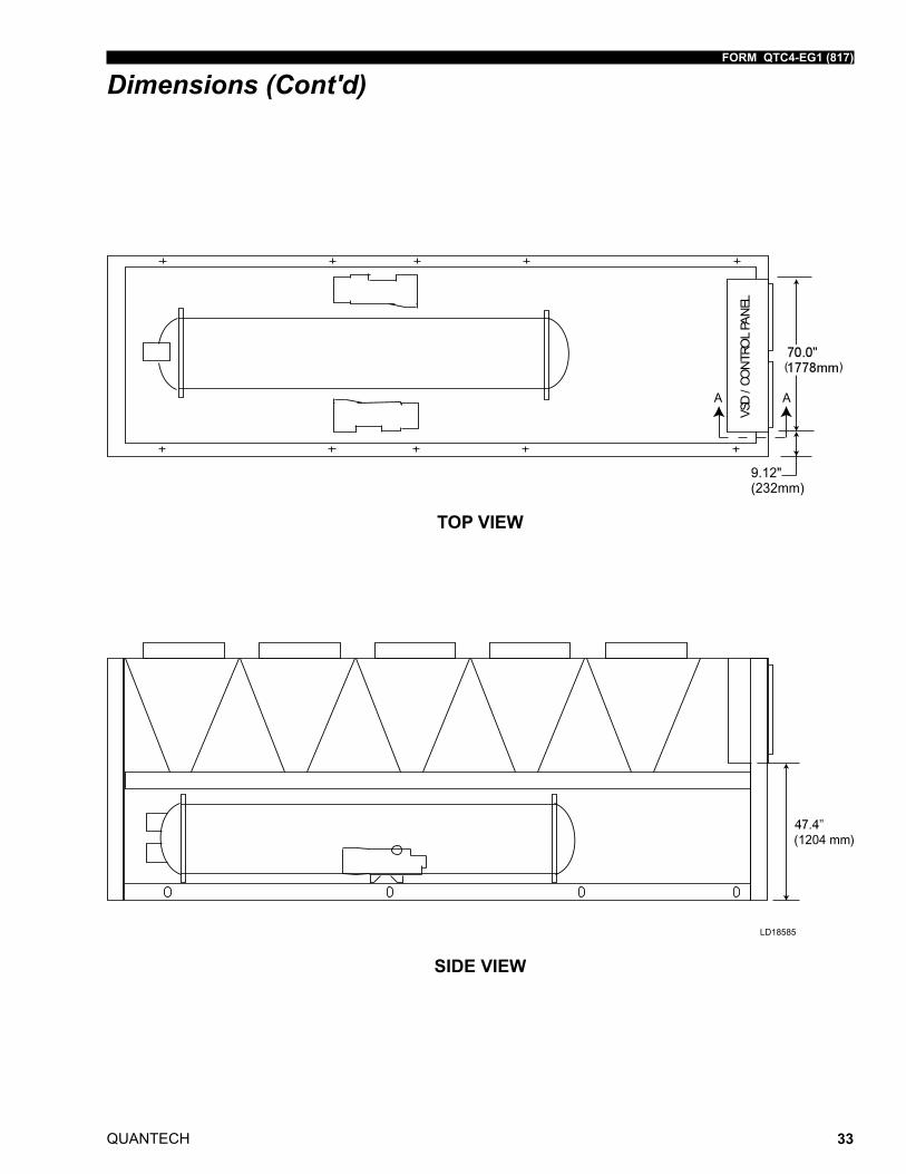
Dimensions (Cont'd)
LD18585
TOP VIEW
SIDE VIEW
QUANTECH
FORM QTC4-EG1 (817)
34
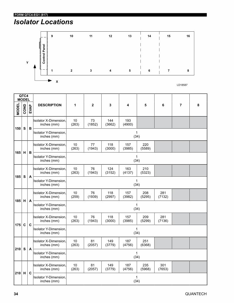
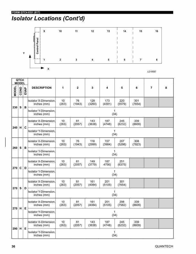
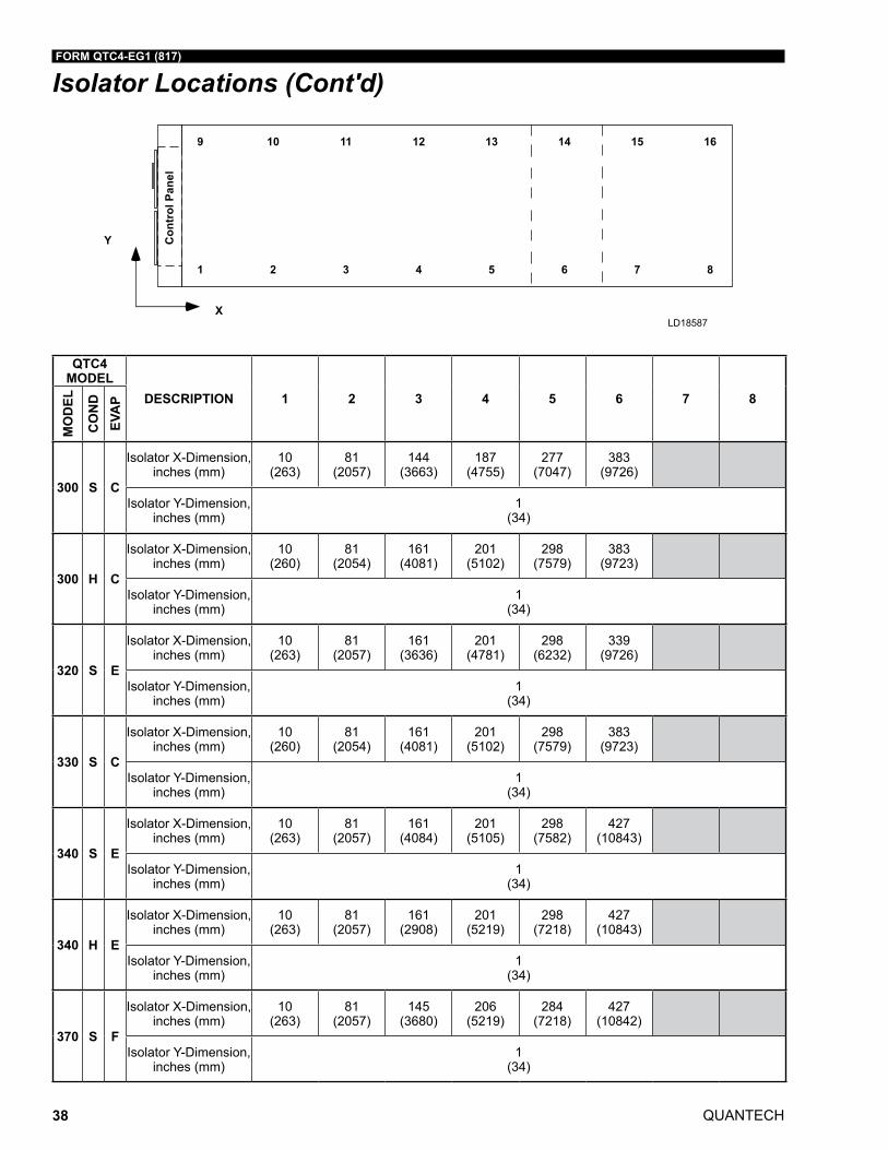
LD18587
Isolator Locations
QTC4 MODEL
DESCRIPTION 1 2 3 4 5 6 7 8
QTC4 MODEL
DESCRIPTION 9 10 11 12 13 14 15 16
MO
DEL
CO
ND
EVA
P
MO
DEL
CO
ND
EVA
P
150 S B
Isolator X-Dimension, inches (mm)
10 (263)
73 (1852)
144 (3662)
193 (4900)
150 S B
Isolator X-Dimension, inches (mm)
10 (263)
73 (1852)
144 (3662)
193 (4900)
Isolator Y-Dimension, inches (mm)
1 (34)
Isolator Y-Dimension, inches (mm)
87 (2206)
165 H B
Isolator X-Dimension, inches (mm)
10 (263)
77 (1943)
118 (3000)
157 (3985)
220 (5589)
165 H B
Isolator X-Dimension, inches (mm)
10 (263)
77 (1943)
118 (3000)
157 (3985)
220 (5589)
Isolator Y-Dimension, inches (mm)
1 (34)
Isolator Y-Dimension, inches (mm)
87 (2206)
185 S A
Isolator X-Dimension, inches (mm)
10 (263)
76 (1943)
124 (3152)
163 (4137)
210 (5323)
185 S A
Isolator X-Dimension, inches (mm)
10 (263)
76 (1943)
124 (3152)
163 (4137)
210 (5323)
Isolator Y-Dimension, inches (mm)
1 (34)
Isolator Y-Dimension, inches (mm)
87 (2206)
185 H A
Isolator X-Dimension, inches (mm)
10 (259)
76 (1939)
118 (2997)
157 (3982)
208 (5295)
281 (7132)
185 H A
Isolator X-Dimension, inches (mm)
10 (259)
76 (1939)
118 (2997)
157 (3982)
208 (5295)
281 (7132)
Isolator Y-Dimension, inches (mm)
1 (34)
Isolator Y-Dimension, inches (mm)
87 (2206)
175 C C
Isolator X-Dimension, inches (mm)
10 (263)
76 (1943)
118 (3000)
157 (3985)
209 (5299)
281 (7136)
175 C C
Isolator X-Dimension, inches (mm)
10 (263)
76 (1943)
118 (3000)
157 (3985)
209 (5299)
281 (7136)
Isolator Y-Dimension, inches (mm)
1 (34)
Isolator Y-Dimension, inches (mm)
87 (2206)
210 S A
Isolator X-Dimension, inches (mm)
10 (263)
81 (2057)
149 (3779)
187 (4756)
251 (6368)
210 S A
Isolator X-Dimension, inches (mm)
10 (263)
81 (2057)
149 (3779)
187 (4756)
251 (6368)
Isolator Y-Dimension, inches (mm)
1 (34)
Isolator Y-Dimension, inches (mm)
87 (2206)
210 H C
Isolator X-Dimension, inches (mm)
10 (263)
81 (2057)
149 (3779)
187 (4756)
235 (5968)
301 (7653)
210 H C
Isolator X-Dimension, inches (mm)
10 (263)
81 (2057)
149 (3779)
187 (4756)
235 (5968)
301 (7653)
Isolator Y-Dimension, inches (mm)
1 (34)
Isolator Y-Dimension, inches (mm)
87 (2206)
FORM QTC4-EG1 (817)
QUANTECH 35
QTC4 MODEL
DESCRIPTION 1 2 3 4 5 6 7 8
QTC4 MODEL
DESCRIPTION 9 10 11 12 13 14 15 16
MO
DEL
CO
ND
EVA
P
MO
DEL
CO
ND
EVA
P
150 S B
Isolator X-Dimension, inches (mm)
10 (263)
73 (1852)
144 (3662)
193 (4900)
150 S B
Isolator X-Dimension, inches (mm)
10 (263)
73 (1852)
144 (3662)
193 (4900)
Isolator Y-Dimension, inches (mm)
1 (34)
Isolator Y-Dimension, inches (mm)
87 (2206)
165 H B
Isolator X-Dimension, inches (mm)
10 (263)
77 (1943)
118 (3000)
157 (3985)
220 (5589)
165 H B
Isolator X-Dimension, inches (mm)
10 (263)
77 (1943)
118 (3000)
157 (3985)
220 (5589)
Isolator Y-Dimension, inches (mm)
1 (34)
Isolator Y-Dimension, inches (mm)
87 (2206)
185 S A
Isolator X-Dimension, inches (mm)
10 (263)
76 (1943)
124 (3152)
163 (4137)
210 (5323)
185 S A
Isolator X-Dimension, inches (mm)
10 (263)
76 (1943)
124 (3152)
163 (4137)
210 (5323)
Isolator Y-Dimension, inches (mm)
1 (34)
Isolator Y-Dimension, inches (mm)
87 (2206)
185 H A
Isolator X-Dimension, inches (mm)
10 (259)
76 (1939)
118 (2997)
157 (3982)
208 (5295)
281 (7132)
185 H A
Isolator X-Dimension, inches (mm)
10 (259)
76 (1939)
118 (2997)
157 (3982)
208 (5295)
281 (7132)
Isolator Y-Dimension, inches (mm)
1 (34)
Isolator Y-Dimension, inches (mm)
87 (2206)
175 C C
Isolator X-Dimension, inches (mm)
10 (263)
76 (1943)
118 (3000)
157 (3985)
209 (5299)
281 (7136)
175 C C
Isolator X-Dimension, inches (mm)
10 (263)
76 (1943)
118 (3000)
157 (3985)
209 (5299)
281 (7136)
Isolator Y-Dimension, inches (mm)
1 (34)
Isolator Y-Dimension, inches (mm)
87 (2206)
210 S A
Isolator X-Dimension, inches (mm)
10 (263)
81 (2057)
149 (3779)
187 (4756)
251 (6368)
210 S A
Isolator X-Dimension, inches (mm)
10 (263)
81 (2057)
149 (3779)
187 (4756)
251 (6368)
Isolator Y-Dimension, inches (mm)
1 (34)
Isolator Y-Dimension, inches (mm)
87 (2206)
210 H C
Isolator X-Dimension, inches (mm)
10 (263)
81 (2057)
149 (3779)
187 (4756)
235 (5968)
301 (7653)
210 H C
Isolator X-Dimension, inches (mm)
10 (263)
81 (2057)
149 (3779)
187 (4756)
235 (5968)
301 (7653)
Isolator Y-Dimension, inches (mm)
1 (34)
Isolator Y-Dimension, inches (mm)
87 (2206)
LD18587
Isolator Locations (Cont'd)
QUANTECH
FORM QTC4-EG1 (817)
36
LD18587
Isolator Locations (Cont'd)
QTC4 MODEL
DESCRIPTION 1 2 3 4 5 6 7 8
QTC4 MODEL
DESCRIPTION 9 10 11 12 13 14 15 16
MO
DEL
CO
ND
EVA
P
MO
DEL
CO
ND
EVA
P
230 S B
Isolator X-Dimension, inches (mm)
10 (263)
76 (1943)
128 (3260)
173 (4391)
220 (5579)
301 (7654)
230 S B
Isolator X-Dimension, inches (mm)
10 (263)
76 (1943)
128 (3260)
173 (4391)
220 (5579)
301 (7654)
Isolator Y-Dimension, inches (mm)
1 (34)
Isolator Y-Dimension, inches (mm)
87 (2206)
240 H C
Isolator X-Dimension, inches (mm)
10 (263)
81 (2057)
143 (3638)
187 (4748)
245 (6232)
339 (8609)
240 H C
Isolator X-Dimension, inches (mm)
10 (263)
81 (2057)
143 (3638)
187 (4748)
245 (6232)
339 (8609)
Isolator Y-Dimension, inches (mm)
1 (34)
Isolator Y-Dimension, inches (mm)
87 (2206)
260 S B
Isolator X-Dimension, inches (mm)
10 (263)
76 (1943)
118 (2999)
157 (3984)
207 (5298)
308 (7823)
260 S B
Isolator X-Dimension, inches (mm)
10 (263)
76 (1943)
118 (2999)
157 (3984)
207 (5298)
308 (7823)
Isolator Y-Dimension, inches (mm)
1 (34)
Isolator Y-Dimension, inches (mm)
87 (2206)
270 C D
Isolator X-Dimension, inches (mm)
10 (263)
81 (2057)
149 (3779)
187 4756)
251 (6375)
270 C D
Isolator X-Dimension, inches (mm)
10 (263)
81 (2057)
149 (3779)
187 4756)
251 (6375)
Isolator Y-Dimension, inches (mm)
1 (34)
Isolator Y-Dimension, inches (mm)
1 (34)
270 S D
Isolator X-Dimension, inches (mm)
10 (263)
81 (2057)
161 (4084)
201 (5105)
301 (7654)
270 S D
Isolator X-Dimension, inches (mm)
10 (263)
81 (2057)
161 (4084)
201 (5105)
301 (7654)
Isolator Y-Dimension, inches (mm)
1 (34)
Isolator Y-Dimension, inches (mm)
87 (2206)
270 H E
Isolator X-Dimension, inches (mm)
10 (263)
81 (2057)
161 (4084)
201 (5105)
298 (7582)
339 (8609)
270 H E
Isolator X-Dimension, inches (mm)
10 (263)
81 (2057)
161 (4084)
201 (5105)
298 (7582)
339 (8609)
Isolator Y-Dimension, inches (mm)
1 (34)
Isolator Y-Dimension, inches (mm)
87 (2206)
290 H E
Isolator X-Dimension, inches (mm)
10 (263)
81 (2057)
143 (3638)
187 (4748)
245 (6232)
339 (8609)
290 H E
Isolator X-Dimension, inches (mm)
10 (259)
81 (2055)
143 (3635)
187 (4745)
245 (6228)
339 (8606)
Isolator Y-Dimension, inches (mm)
1 (34)
Isolator Y-Dimension, inches (mm)
87 (2206)
FORM QTC4-EG1 (817)
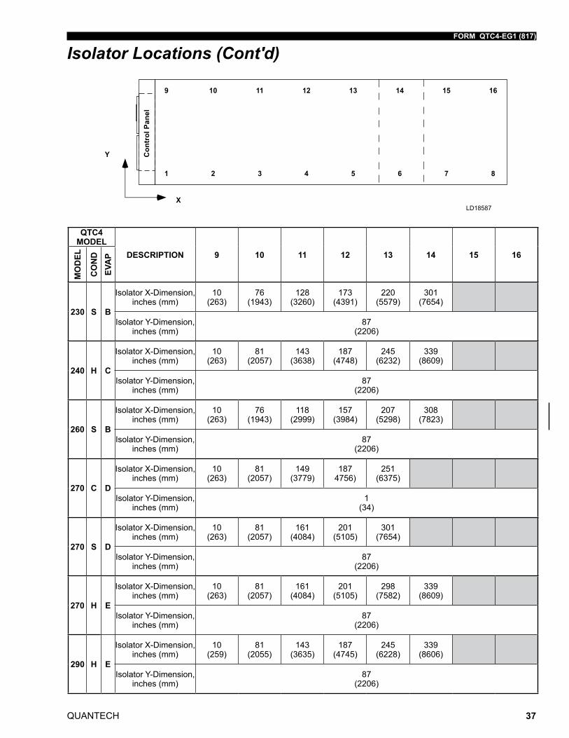
QUANTECH 37
QTC4 MODEL
DESCRIPTION 1 2 3 4 5 6 7 8
QTC4 MODEL
DESCRIPTION 9 10 11 12 13 14 15 16
MO
DEL
CO
ND
EVA
P
MO
DEL
CO
ND
EVA
P
230 S B
Isolator X-Dimension, inches (mm)
10 (263)
76 (1943)
128 (3260)
173 (4391)
220 (5579)
301 (7654)
230 S B
Isolator X-Dimension, inches (mm)
10 (263)
76 (1943)
128 (3260)
173 (4391)
220 (5579)
301 (7654)
Isolator Y-Dimension, inches (mm)
1 (34)
Isolator Y-Dimension, inches (mm)
87 (2206)
240 H C
Isolator X-Dimension, inches (mm)
10 (263)
81 (2057)
143 (3638)
187 (4748)
245 (6232)
339 (8609)
240 H C
Isolator X-Dimension, inches (mm)
10 (263)
81 (2057)
143 (3638)
187 (4748)
245 (6232)
339 (8609)
Isolator Y-Dimension, inches (mm)
1 (34)
Isolator Y-Dimension, inches (mm)
87 (2206)
260 S B
Isolator X-Dimension, inches (mm)
10 (263)
76 (1943)
118 (2999)
157 (3984)
207 (5298)
308 (7823)
260 S B
Isolator X-Dimension, inches (mm)
10 (263)
76 (1943)
118 (2999)
157 (3984)
207 (5298)
308 (7823)
Isolator Y-Dimension, inches (mm)
1 (34)
Isolator Y-Dimension, inches (mm)
87 (2206)
270 C D
Isolator X-Dimension, inches (mm)
10 (263)
81 (2057)
149 (3779)
187 4756)
251 (6375)
270 C D
Isolator X-Dimension, inches (mm)
10 (263)
81 (2057)
149 (3779)
187 4756)
251 (6375)
Isolator Y-Dimension, inches (mm)
1 (34)
Isolator Y-Dimension, inches (mm)
1 (34)
270 S D
Isolator X-Dimension, inches (mm)
10 (263)
81 (2057)
161 (4084)
201 (5105)
301 (7654)
270 S D
Isolator X-Dimension, inches (mm)
10 (263)
81 (2057)
161 (4084)
201 (5105)
301 (7654)
Isolator Y-Dimension, inches (mm)
1 (34)
Isolator Y-Dimension, inches (mm)
87 (2206)
270 H E
Isolator X-Dimension, inches (mm)
10 (263)
81 (2057)
161 (4084)
201 (5105)
298 (7582)
339 (8609)
270 H E
Isolator X-Dimension, inches (mm)
10 (263)
81 (2057)
161 (4084)
201 (5105)
298 (7582)
339 (8609)
Isolator Y-Dimension, inches (mm)
1 (34)
Isolator Y-Dimension, inches (mm)
87 (2206)
290 H E
Isolator X-Dimension, inches (mm)
10 (263)
81 (2057)
143 (3638)
187 (4748)
245 (6232)
339 (8609)
290 H E
Isolator X-Dimension, inches (mm)
10 (259)
81 (2055)
143 (3635)
187 (4745)
245 (6228)
339 (8606)
Isolator Y-Dimension, inches (mm)
1 (34)
Isolator Y-Dimension, inches (mm)
87 (2206)
LD18587
Isolator Locations (Cont'd)
QUANTECH
FORM QTC4-EG1 (817)
38
Isolator Locations (Cont'd)
QTC4 MODEL
DESCRIPTION 1 2 3 4 5 6 7 8
QTC4 MODEL
DESCRIPTION 9 10 11 12 13 14 15 16
MO
DEL
CO
ND
EVA
P
MO
DEL
CO
ND
EVA
P
300 S C
Isolator X-Dimension, inches (mm)
10 (263)
81 (2057)
144 (3663)
187 (4755)
277 (7047)
383 (9726)
300 S C
Isolator X-Dimension, inches (mm)
10 (263)
81 (2057)
144 (3663)
187 (4755)
277 (7047)
383 (9726)
Isolator Y-Dimension, inches (mm)
1 (34)
Isolator Y-Dimension, inches (mm)
87 (2206)
300 H C
Isolator X-Dimension, inches (mm)
10 (260)
81 (2054)
161 (4081)
201 (5102)
298 (7579)
383 (9723)
300 H C
Isolator X-Dimension, inches (mm)
10 (260)
81 (2054)
161 (4081)
201 (5102)
298 (7579)
383 (9723)
Isolator Y-Dimension, inches (mm)
1 (34)
Isolator Y-Dimension, inches (mm)
87 (2206)
320 S E
Isolator X-Dimension, inches (mm)
10 (263)
81 (2057)
161 (3636)
201 (4781)
298 (6232)
339 (9726)
320 S E
Isolator X-Dimension, inches (mm)
10 (263)
81 (2057)
143 (3636)
188 (4781)
245 (6232)
383 (9726)
Isolator Y-Dimension, inches (mm)
1 (34)
Isolator Y-Dimension, inches (mm)
87 (2206)
330 S C
Isolator X-Dimension, inches (mm)
10 (260)
81 (2054)
161 (4081)
201 (5102)
298 (7579)
383 (9723)
330 S C
Isolator X-Dimension, inches (mm)
10 (260)
81 (2054)
161 (4081)
201 (5102)
298 (7579)
383 (9723)
Isolator Y-Dimension, inches (mm)
1 (34)
Isolator Y-Dimension, inches (mm)
87 (2206)
340 S E
Isolator X-Dimension, inches (mm)
10 (263)
81 (2057)
161 (4084)
201 (5105)
298 (7582)
427 (10843)
340 S E
Isolator X-Dimension, inches (mm)
10 (263)
81 (2057)
161 (4084)
201 (5105)
298 (7582)
427 (10843)
Isolator Y-Dimension, inches (mm)
1 (34)
Isolator Y-Dimension, inches (mm)
87 (2206)
340 H E
Isolator X-Dimension, inches (mm)
10 (263)
81 (2057)
161 (2908)
201 (5219)
298 (7218)
427 (10843)
340 H E
Isolator X-Dimension, inches (mm)
10 (263)
81 (2057)
161 (2908)
201 (5219)
298 (7218)
427 (10843)
Isolator Y-Dimension, inches (mm)
1 (34)
Isolator Y-Dimension, inches (mm)
87 (2206)
370 S F
Isolator X-Dimension, inches (mm)
10 (263)
81 (2057)
145 (3680)
206 (5219)
284 (7218)
427 (10842)
370 S F
Isolator X-Dimension, inches (mm)
10 (263)
81 (2057)
145 (3680)
206 (5219)
284 (7218)
427 (10842)
Isolator Y-Dimension, inches (mm)
1 (34)
Isolator Y-Dimension, inches (mm)
87 (2206)
LD18587
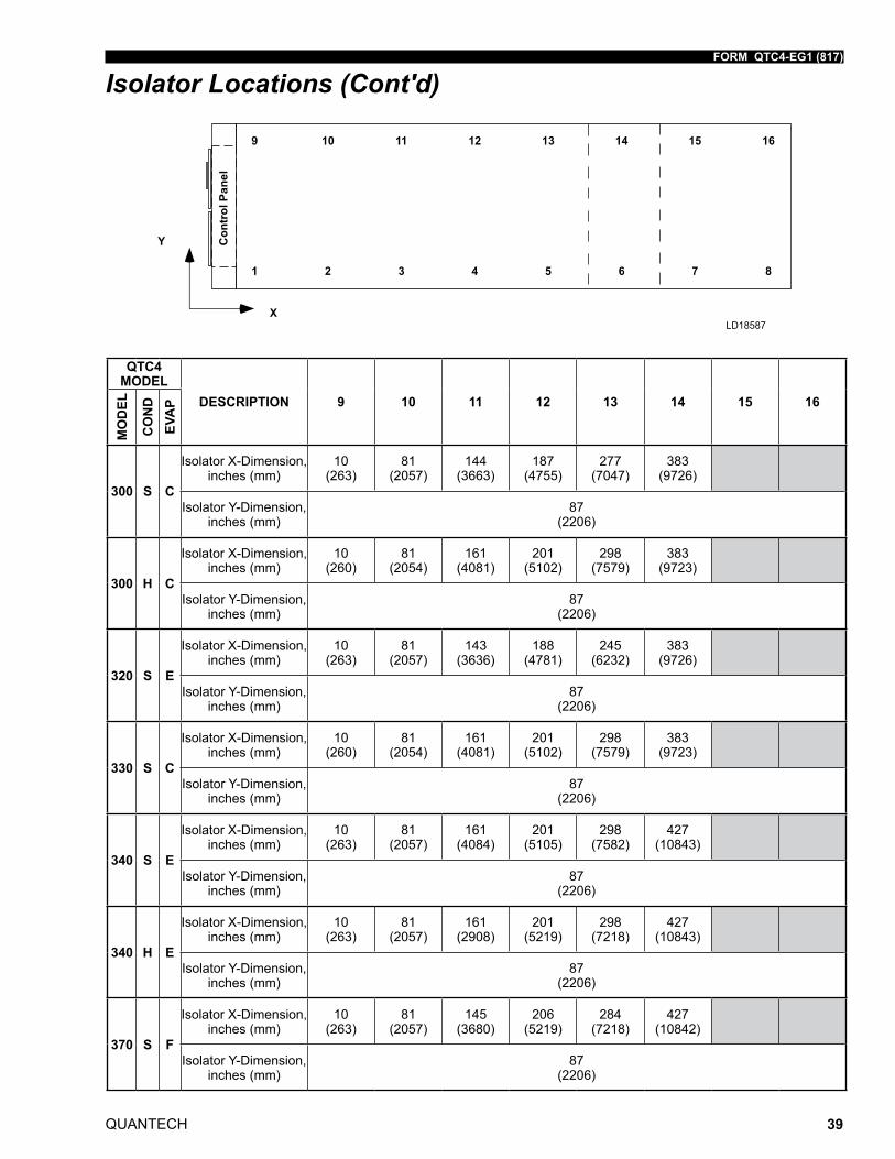
FORM QTC4-EG1 (817)
QUANTECH 39
QTC4 MODEL
DESCRIPTION 1 2 3 4 5 6 7 8
QTC4 MODEL
DESCRIPTION 9 10 11 12 13 14 15 16
MO
DEL
CO
ND
EVA
P
MO
DEL
CO
ND
EVA
P
300 S C
Isolator X-Dimension, inches (mm)
10 (263)
81 (2057)
144 (3663)
187 (4755)
277 (7047)
383 (9726)
300 S C
Isolator X-Dimension, inches (mm)
10 (263)
81 (2057)
144 (3663)
187 (4755)
277 (7047)
383 (9726)
Isolator Y-Dimension, inches (mm)
1 (34)
Isolator Y-Dimension, inches (mm)
87 (2206)
300 H C
Isolator X-Dimension, inches (mm)
10 (260)
81 (2054)
161 (4081)
201 (5102)
298 (7579)
383 (9723)
300 H C
Isolator X-Dimension, inches (mm)
10 (260)
81 (2054)
161 (4081)
201 (5102)
298 (7579)
383 (9723)
Isolator Y-Dimension, inches (mm)
1 (34)
Isolator Y-Dimension, inches (mm)
87 (2206)
320 S E
Isolator X-Dimension, inches (mm)
10 (263)
81 (2057)
161 (3636)
201 (4781)
298 (6232)
339 (9726)
320 S E
Isolator X-Dimension, inches (mm)
10 (263)
81 (2057)
143 (3636)
188 (4781)
245 (6232)
383 (9726)
Isolator Y-Dimension, inches (mm)
1 (34)
Isolator Y-Dimension, inches (mm)
87 (2206)
330 S C
Isolator X-Dimension, inches (mm)
10 (260)
81 (2054)
161 (4081)
201 (5102)
298 (7579)
383 (9723)
330 S C
Isolator X-Dimension, inches (mm)
10 (260)
81 (2054)
161 (4081)
201 (5102)
298 (7579)
383 (9723)
Isolator Y-Dimension, inches (mm)
1 (34)
Isolator Y-Dimension, inches (mm)
87 (2206)
340 S E
Isolator X-Dimension, inches (mm)
10 (263)
81 (2057)
161 (4084)
201 (5105)
298 (7582)
427 (10843)
340 S E
Isolator X-Dimension, inches (mm)
10 (263)
81 (2057)
161 (4084)
201 (5105)
298 (7582)
427 (10843)
Isolator Y-Dimension, inches (mm)
1 (34)
Isolator Y-Dimension, inches (mm)
87 (2206)
340 H E
Isolator X-Dimension, inches (mm)
10 (263)
81 (2057)
161 (2908)
201 (5219)
298 (7218)
427 (10843)
340 H E
Isolator X-Dimension, inches (mm)
10 (263)
81 (2057)
161 (2908)
201 (5219)
298 (7218)
427 (10843)
Isolator Y-Dimension, inches (mm)
1 (34)
Isolator Y-Dimension, inches (mm)
87 (2206)
370 S F
Isolator X-Dimension, inches (mm)
10 (263)
81 (2057)
145 (3680)
206 (5219)
284 (7218)
427 (10842)
370 S F
Isolator X-Dimension, inches (mm)
10 (263)
81 (2057)
145 (3680)
206 (5219)
284 (7218)
427 (10842)
Isolator Y-Dimension, inches (mm)
1 (34)
Isolator Y-Dimension, inches (mm)
87 (2206)
LD18587
Isolator Locations (Cont'd)
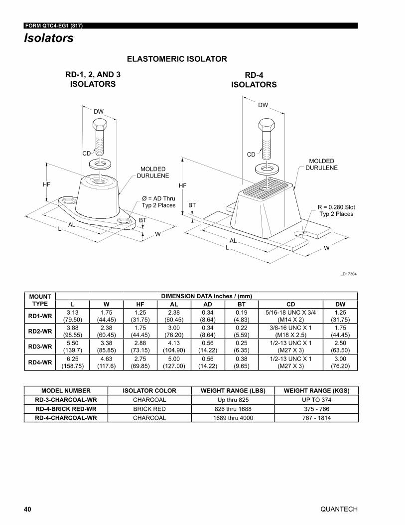
QUANTECH
FORM QTC4-EG1 (817)
40
Isolators
RD-1, 2, AND 3 ISOLATORS
ELASTOMERIC ISOLATOR
LD17304
CDCD
HFHF
BT
BT
ALL
ALL
W
W
DWDW
MOLDEDDURULENEMOLDED
DURULENE
R = 0.280 SlotTyp 2 Places
Ø = AD ThruTyp 2 Places
RD-4 ISOLATORS
MOUNTTYPE
DIMENSION DATA inches / (mm)L W HF AL AD BT CD DW
RD1-WR 3.13(79.50)
1.75(44.45)
1.25(31.75)
2.38(60.45)
0.34(8.64)
0.19(4.83)
5/16-18 UNC X 3/4(M14 X 2)
1.25(31.75)
RD2-WR 3.88(98.55)
2.38(60.45)
1.75(44.45)
3.00(76.20)
0.34(8.64)
0.22(5.59)
3/8-16 UNC X 1(M18 X 2.5)
1.75(44.45)
RD3-WR 5.50(139.7)
3.38(85.85)
2.88(73.15)
4.13(104.90)
0.56(14.22)
0.25(6.35)
1/2-13 UNC X 1(M27 X 3)
2.50(63.50)
RD4-WR 6.25(158.75)
4.63(117.6)
2.75(69.85)
5.00(127.00)
0.56(14.22)
0.38(9.65)
1/2-13 UNC X 1(M27 X 3)
3.00(76.20)
MODEL NUMBER ISOLATOR COLOR WEIGHT RANGE (LBS) WEIGHT RANGE (KGS)RD-3-CHARCOAL-WR CHARCOAL Up thru 825 UP TO 374RD-4-BRICK RED-WR BRICK RED 826 thru 1688 375 - 766RD-4-CHARCOAL-WR CHARCOAL 1689 thru 4000 767 - 1814
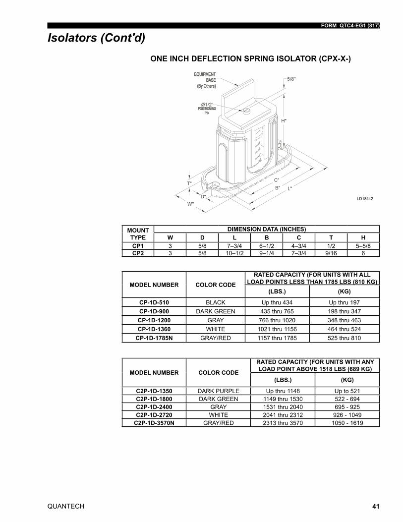
FORM QTC4-EG1 (817)
QUANTECH 41
LD18442
MOUNT TYPE
DIMENSION DATA (INCHES)W D L B C T H
CP1 3 5/8 7–3/4 6–1/2 4–3/4 1/2 5–5/8CP2 3 5/8 10–1/2 9–1/4 7–3/4 9/16 6
ONE INCH DEFLECTION SPRING ISOLATOR (CPX-X-)
Isolators (Cont'd)
MODEL NUMBER COLOR CODERATED CAPACITY (FOR UNITS WITH ALL
LOAD POINTS LESS THAN 1785 LBS (810 KG)(LBS.) (KG)
CP-1D-510 BLACK Up thru 434 Up thru 197CP-1D-900 DARK GREEN 435 thru 765 198 thru 347
CP-1D-1200 GRAY 766 thru 1020 348 thru 463CP-1D-1360 WHITE 1021 thru 1156 464 thru 524
CP-1D-1785N GRAY/RED 1157 thru 1785 525 thru 810
MODEL NUMBER COLOR CODE
RATED CAPACITY (FOR UNITS WITH ANY LOAD POINT ABOVE 1518 LBS (689 KG)
(LBS.) (KG)
C2P-1D-1350 DARK PURPLE Up thru 1148 Up to 521C2P-1D-1800 DARK GREEN 1149 thru 1530 522 - 694C2P-1D-2400 GRAY 1531 thru 2040 695 - 925C2P-1D-2720 WHITE 2041 thru 2312 926 - 1049
C2P-1D-3570N GRAY/RED 2313 thru 3570 1050 - 1619
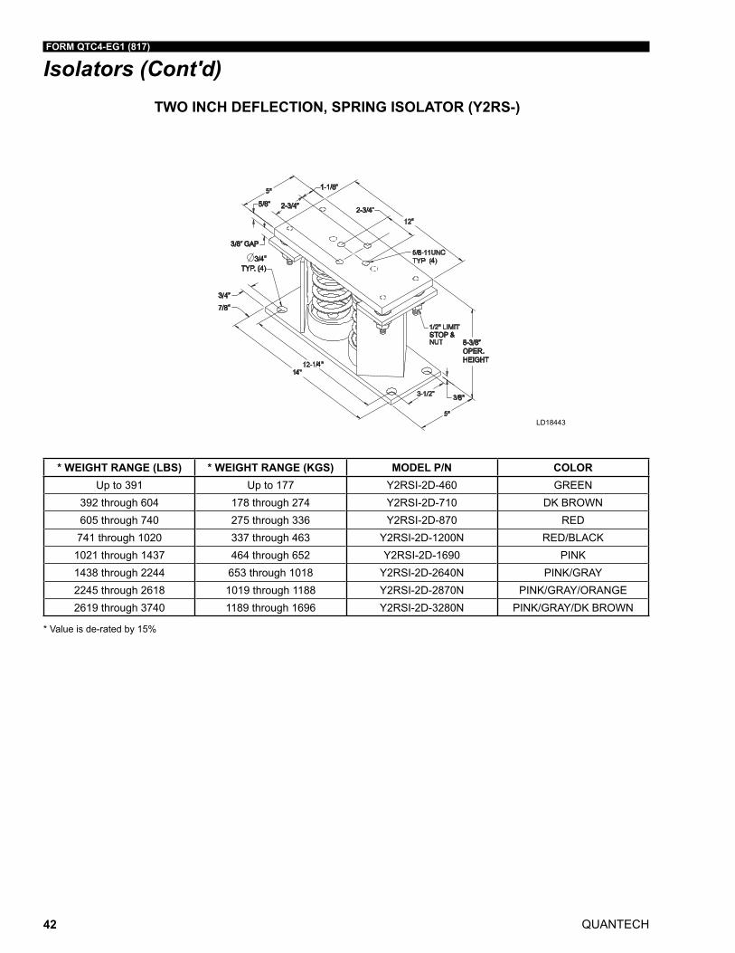
QUANTECH
FORM QTC4-EG1 (817)
42
TWO INCH DEFLECTION, SPRING ISOLATOR (Y2RS-)
3/4”
7/8”
3/8” GAP
3/4”TYP. (4)
5/8” 2-3/4”
1-1/8”
2-3/4”
8P
4
8
STOP &8-3/8”OPER.HEIGHT
4
4
LD18443
Isolators (Cont'd)
* WEIGHT RANGE (LBS) * WEIGHT RANGE (KGS) MODEL P/N COLORUp to 391 Up to 177 Y2RSI-2D-460 GREEN
392 through 604 178 through 274 Y2RSI-2D-710 DK BROWN605 through 740 275 through 336 Y2RSI-2D-870 RED
741 through 1020 337 through 463 Y2RSI-2D-1200N RED/BLACK1021 through 1437 464 through 652 Y2RSI-2D-1690 PINK1438 through 2244 653 through 1018 Y2RSI-2D-2640N PINK/GRAY2245 through 2618 1019 through 1188 Y2RSI-2D-2870N PINK/GRAY/ORANGE2619 through 3740 1189 through 1696 Y2RSI-2D-3280N PINK/GRAY/DK BROWN
* Value is de-rated by 15%
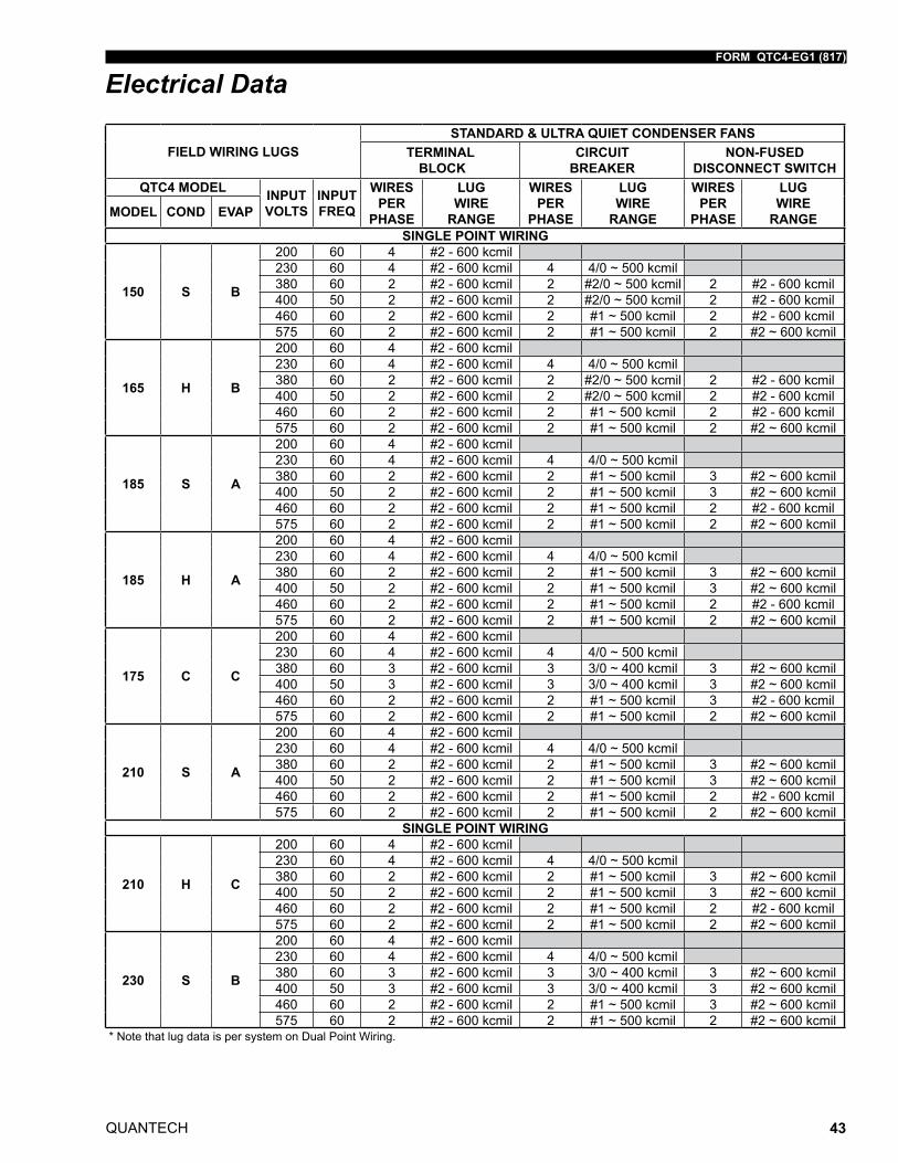
FORM QTC4-EG1 (817)
QUANTECH 43
Electrical Data
FIELD WIRING LUGSSTANDARD & ULTRA QUIET CONDENSER FANS
TERMINAL BLOCK
CIRCUIT BREAKER
NON-FUSED DISCONNECT SWITCH
QTC4 MODEL INPUT VOLTS
INPUT FREQ
WIRES PER
PHASE
LUG WIRE
RANGE
WIRES PER
PHASE
LUG WIRE
RANGE
WIRES PER
PHASE
LUG WIRE
RANGEMODEL COND EVAP
SINGLE POINT WIRING
150 S B
200 60 4 #2 - 600 kcmil230 60 4 #2 - 600 kcmil 4 4/0 ~ 500 kcmil380 60 2 #2 - 600 kcmil 2 #2/0 ~ 500 kcmil 2 #2 - 600 kcmil400 50 2 #2 - 600 kcmil 2 #2/0 ~ 500 kcmil 2 #2 - 600 kcmil460 60 2 #2 - 600 kcmil 2 #1 ~ 500 kcmil 2 #2 - 600 kcmil575 60 2 #2 - 600 kcmil 2 #1 ~ 500 kcmil 2 #2 ~ 600 kcmil
165 H B
200 60 4 #2 - 600 kcmil230 60 4 #2 - 600 kcmil 4 4/0 ~ 500 kcmil380 60 2 #2 - 600 kcmil 2 #2/0 ~ 500 kcmil 2 #2 - 600 kcmil400 50 2 #2 - 600 kcmil 2 #2/0 ~ 500 kcmil 2 #2 - 600 kcmil460 60 2 #2 - 600 kcmil 2 #1 ~ 500 kcmil 2 #2 - 600 kcmil575 60 2 #2 - 600 kcmil 2 #1 ~ 500 kcmil 2 #2 ~ 600 kcmil
185 S A
200 60 4 #2 - 600 kcmil230 60 4 #2 - 600 kcmil 4 4/0 ~ 500 kcmil380 60 2 #2 - 600 kcmil 2 #1 ~ 500 kcmil 3 #2 ~ 600 kcmil400 50 2 #2 - 600 kcmil 2 #1 ~ 500 kcmil 3 #2 ~ 600 kcmil460 60 2 #2 - 600 kcmil 2 #1 ~ 500 kcmil 2 #2 - 600 kcmil575 60 2 #2 - 600 kcmil 2 #1 ~ 500 kcmil 2 #2 ~ 600 kcmil
185 H A
200 60 4 #2 - 600 kcmil230 60 4 #2 - 600 kcmil 4 4/0 ~ 500 kcmil380 60 2 #2 - 600 kcmil 2 #1 ~ 500 kcmil 3 #2 ~ 600 kcmil400 50 2 #2 - 600 kcmil 2 #1 ~ 500 kcmil 3 #2 ~ 600 kcmil460 60 2 #2 - 600 kcmil 2 #1 ~ 500 kcmil 2 #2 - 600 kcmil575 60 2 #2 - 600 kcmil 2 #1 ~ 500 kcmil 2 #2 ~ 600 kcmil
175 C C
200 60 4 #2 - 600 kcmil230 60 4 #2 - 600 kcmil 4 4/0 ~ 500 kcmil380 60 3 #2 - 600 kcmil 3 3/0 ~ 400 kcmil 3 #2 ~ 600 kcmil400 50 3 #2 - 600 kcmil 3 3/0 ~ 400 kcmil 3 #2 ~ 600 kcmil460 60 2 #2 - 600 kcmil 2 #1 ~ 500 kcmil 3 #2 - 600 kcmil575 60 2 #2 - 600 kcmil 2 #1 ~ 500 kcmil 2 #2 ~ 600 kcmil
210 S A
200 60 4 #2 - 600 kcmil230 60 4 #2 - 600 kcmil 4 4/0 ~ 500 kcmil380 60 2 #2 - 600 kcmil 2 #1 ~ 500 kcmil 3 #2 ~ 600 kcmil400 50 2 #2 - 600 kcmil 2 #1 ~ 500 kcmil 3 #2 ~ 600 kcmil460 60 2 #2 - 600 kcmil 2 #1 ~ 500 kcmil 2 #2 - 600 kcmil575 60 2 #2 - 600 kcmil 2 #1 ~ 500 kcmil 2 #2 ~ 600 kcmil
SINGLE POINT WIRING
210 H C
200 60 4 #2 - 600 kcmil230 60 4 #2 - 600 kcmil 4 4/0 ~ 500 kcmil380 60 2 #2 - 600 kcmil 2 #1 ~ 500 kcmil 3 #2 ~ 600 kcmil400 50 2 #2 - 600 kcmil 2 #1 ~ 500 kcmil 3 #2 ~ 600 kcmil460 60 2 #2 - 600 kcmil 2 #1 ~ 500 kcmil 2 #2 - 600 kcmil575 60 2 #2 - 600 kcmil 2 #1 ~ 500 kcmil 2 #2 ~ 600 kcmil
230 S B
200 60 4 #2 - 600 kcmil230 60 4 #2 - 600 kcmil 4 4/0 ~ 500 kcmil380 60 3 #2 - 600 kcmil 3 3/0 ~ 400 kcmil 3 #2 ~ 600 kcmil400 50 3 #2 - 600 kcmil 3 3/0 ~ 400 kcmil 3 #2 ~ 600 kcmil460 60 2 #2 - 600 kcmil 2 #1 ~ 500 kcmil 3 #2 ~ 600 kcmil575 60 2 #2 - 600 kcmil 2 #1 ~ 500 kcmil 2 #2 ~ 600 kcmil
* Note that lug data is per system on Dual Point Wiring.
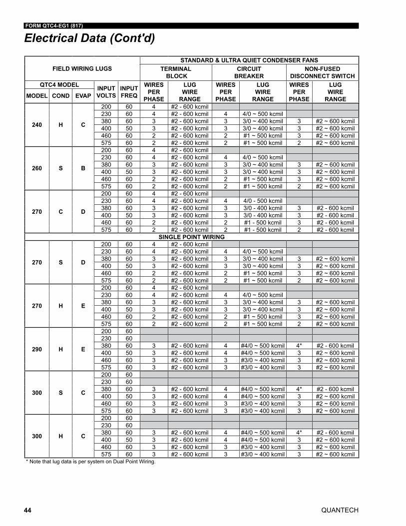
QUANTECH
FORM QTC4-EG1 (817)
44
FIELD WIRING LUGSSTANDARD & ULTRA QUIET CONDENSER FANS
TERMINAL BLOCK
CIRCUIT BREAKER
NON-FUSED DISCONNECT SWITCH
QTC4 MODEL INPUT VOLTS
INPUT FREQ
WIRES PER
PHASE
LUG WIRE
RANGE
WIRES PER
PHASE
LUG WIRE
RANGE
WIRES PER
PHASE
LUG WIRE
RANGEMODEL COND EVAP
240 H C
200 60 4 #2 - 600 kcmil230 60 4 #2 - 600 kcmil 4 4/0 ~ 500 kcmil380 60 3 #2 - 600 kcmil 3 3/0 ~ 400 kcmil 3 #2 ~ 600 kcmil400 50 3 #2 - 600 kcmil 3 3/0 ~ 400 kcmil 3 #2 ~ 600 kcmil460 60 2 #2 - 600 kcmil 2 #1 ~ 500 kcmil 3 #2 ~ 600 kcmil575 60 2 #2 - 600 kcmil 2 #1 ~ 500 kcmil 2 #2 ~ 600 kcmil
260 S B
200 60 4 #2 - 600 kcmil230 60 4 #2 - 600 kcmil 4 4/0 ~ 500 kcmil380 60 3 #2 - 600 kcmil 3 3/0 ~ 400 kcmil 3 #2 ~ 600 kcmil400 50 3 #2 - 600 kcmil 3 3/0 ~ 400 kcmil 3 #2 ~ 600 kcmil460 60 2 #2 - 600 kcmil 2 #1 ~ 500 kcmil 3 #2 ~ 600 kcmil575 60 2 #2 - 600 kcmil 2 #1 ~ 500 kcmil 2 #2 ~ 600 kcmil
270 C D
200 60 4 #2 - 600 kcmil230 60 4 #2 - 600 kcmil 4 4/0 - 500 kcmil380 60 3 #2 - 600 kcmil 3 3/0 - 400 kcmil 3 #2 - 600 kcmil400 50 3 #2 - 600 kcmil 3 3/0 - 400 kcmil 3 #2 - 600 kcmil460 60 2 #2 - 600 kcmil 2 #1 - 500 kcmil 3 #2 - 600 kcmil575 60 2 #2 - 600 kcmil 2 #1 - 500 kcmil 2 #2 - 600 kcmil
SINGLE POINT WIRING
270 S D
200 60 4 #2 - 600 kcmil230 60 4 #2 - 600 kcmil 4 4/0 ~ 500 kcmil380 60 3 #2 - 600 kcmil 3 3/0 ~ 400 kcmil 3 #2 ~ 600 kcmil400 50 3 #2 - 600 kcmil 3 3/0 ~ 400 kcmil 3 #2 ~ 600 kcmil460 60 2 #2 - 600 kcmil 2 #1 ~ 500 kcmil 3 #2 ~ 600 kcmil575 60 2 #2 - 600 kcmil 2 #1 ~ 500 kcmil 2 #2 ~ 600 kcmil
270 H E
200 60 4 #2 - 600 kcmil230 60 4 #2 - 600 kcmil 4 4/0 ~ 500 kcmil380 60 3 #2 - 600 kcmil 3 3/0 ~ 400 kcmil 3 #2 ~ 600 kcmil400 50 3 #2 - 600 kcmil 3 3/0 ~ 400 kcmil 3 #2 ~ 600 kcmil460 60 2 #2 - 600 kcmil 2 #1 ~ 500 kcmil 3 #2 ~ 600 kcmil575 60 2 #2 - 600 kcmil 2 #1 ~ 500 kcmil 2 #2 ~ 600 kcmil
290 H E
200 60230 60380 60 3 #2 - 600 kcmil 4 #4/0 ~ 500 kcmil 4* #2 - 600 kcmil400 50 3 #2 - 600 kcmil 4 #4/0 ~ 500 kcmil 3 #2 ~ 600 kcmil460 60 3 #2 - 600 kcmil 3 #3/0 ~ 400 kcmil 3 #2 ~ 600 kcmil575 60 3 #2 - 600 kcmil 3 #3/0 ~ 400 kcmil 3 #2 ~ 600 kcmil
300 S C
200 60230 60380 60 3 #2 - 600 kcmil 4 #4/0 ~ 500 kcmil 4* #2 - 600 kcmil400 50 3 #2 - 600 kcmil 4 #4/0 ~ 500 kcmil 3 #2 ~ 600 kcmil460 60 3 #2 - 600 kcmil 3 #3/0 ~ 400 kcmil 3 #2 ~ 600 kcmil575 60 3 #2 - 600 kcmil 3 #3/0 ~ 400 kcmil 3 #2 ~ 600 kcmil
300 H C
200 60230 60380 60 3 #2 - 600 kcmil 4 #4/0 ~ 500 kcmil 4* #2 - 600 kcmil400 50 3 #2 - 600 kcmil 4 #4/0 ~ 500 kcmil 3 #2 ~ 600 kcmil460 60 3 #2 - 600 kcmil 3 #3/0 ~ 400 kcmil 3 #2 ~ 600 kcmil575 60 3 #2 - 600 kcmil 3 #3/0 ~ 400 kcmil 3 #2 ~ 600 kcmil
* Note that lug data is per system on Dual Point Wiring.
Electrical Data (Cont'd)
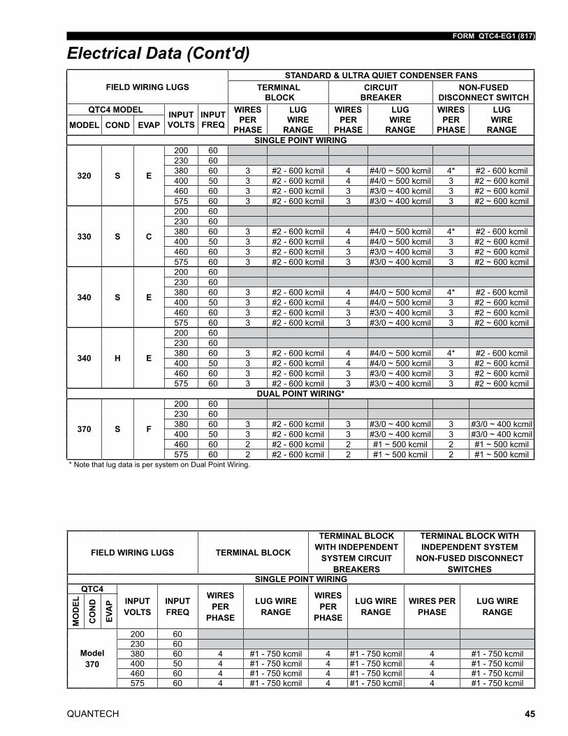
FORM QTC4-EG1 (817)
QUANTECH 45
FIELD WIRING LUGSSTANDARD & ULTRA QUIET CONDENSER FANS
TERMINAL BLOCK
CIRCUIT BREAKER
NON-FUSED DISCONNECT SWITCH
QTC4 MODEL INPUT VOLTS
INPUT FREQ
WIRES PER
PHASE
LUG WIRE
RANGE
WIRES PER
PHASE
LUG WIRE
RANGE
WIRES PER
PHASE
LUG WIRE
RANGEMODEL COND EVAP
SINGLE POINT WIRING
320 S E
200 60230 60380 60 3 #2 - 600 kcmil 4 #4/0 ~ 500 kcmil 4* #2 - 600 kcmil400 50 3 #2 - 600 kcmil 4 #4/0 ~ 500 kcmil 3 #2 ~ 600 kcmil460 60 3 #2 - 600 kcmil 3 #3/0 ~ 400 kcmil 3 #2 ~ 600 kcmil575 60 3 #2 - 600 kcmil 3 #3/0 ~ 400 kcmil 3 #2 ~ 600 kcmil
330 S C
200 60230 60380 60 3 #2 - 600 kcmil 4 #4/0 ~ 500 kcmil 4* #2 - 600 kcmil400 50 3 #2 - 600 kcmil 4 #4/0 ~ 500 kcmil 3 #2 ~ 600 kcmil460 60 3 #2 - 600 kcmil 3 #3/0 ~ 400 kcmil 3 #2 ~ 600 kcmil575 60 3 #2 - 600 kcmil 3 #3/0 ~ 400 kcmil 3 #2 ~ 600 kcmil
340 S E
200 60230 60380 60 3 #2 - 600 kcmil 4 #4/0 ~ 500 kcmil 4* #2 - 600 kcmil400 50 3 #2 - 600 kcmil 4 #4/0 ~ 500 kcmil 3 #2 ~ 600 kcmil460 60 3 #2 - 600 kcmil 3 #3/0 ~ 400 kcmil 3 #2 ~ 600 kcmil575 60 3 #2 - 600 kcmil 3 #3/0 ~ 400 kcmil 3 #2 ~ 600 kcmil
340 H E
200 60230 60380 60 3 #2 - 600 kcmil 4 #4/0 ~ 500 kcmil 4* #2 - 600 kcmil400 50 3 #2 - 600 kcmil 4 #4/0 ~ 500 kcmil 3 #2 ~ 600 kcmil460 60 3 #2 - 600 kcmil 3 #3/0 ~ 400 kcmil 3 #2 ~ 600 kcmil575 60 3 #2 - 600 kcmil 3 #3/0 ~ 400 kcmil 3 #2 ~ 600 kcmil
DUAL POINT WIRING*
370 S F
200 60230 60380 60 3 #2 - 600 kcmil 3 #3/0 ~ 400 kcmil 3 #3/0 ~ 400 kcmil400 50 3 #2 - 600 kcmil 3 #3/0 ~ 400 kcmil 3 #3/0 ~ 400 kcmil460 60 2 #2 - 600 kcmil 2 #1 ~ 500 kcmil 2 #1 ~ 500 kcmil575 60 2 #2 - 600 kcmil 2 #1 ~ 500 kcmil 2 #1 ~ 500 kcmil
* Note that lug data is per system on Dual Point Wiring.
Electrical Data (Cont'd)
FIELD WIRING LUGS TERMINAL BLOCK
TERMINAL BLOCK WITH INDEPENDENT
SYSTEM CIRCUIT BREAKERS
TERMINAL BLOCK WITH INDEPENDENT SYSTEM
NON-FUSED DISCONNECT SWITCHES
SINGLE POINT WIRINGQTC4
INPUT VOLTS
INPUT FREQ
WIRES PER
PHASE
LUG WIRE RANGE
WIRES PER
PHASE
LUG WIRE RANGE
WIRES PER PHASE
LUG WIRE RANGE
MO
DEL
CO
ND
EVA
P
Model 370
200 60230 60380 60 4 #1 - 750 kcmil 4 #1 - 750 kcmil 4 #1 - 750 kcmil400 50 4 #1 - 750 kcmil 4 #1 - 750 kcmil 4 #1 - 750 kcmil460 60 4 #1 - 750 kcmil 4 #1 - 750 kcmil 4 #1 - 750 kcmil575 60 4 #1 - 750 kcmil 4 #1 - 750 kcmil 4 #1 - 750 kcmil
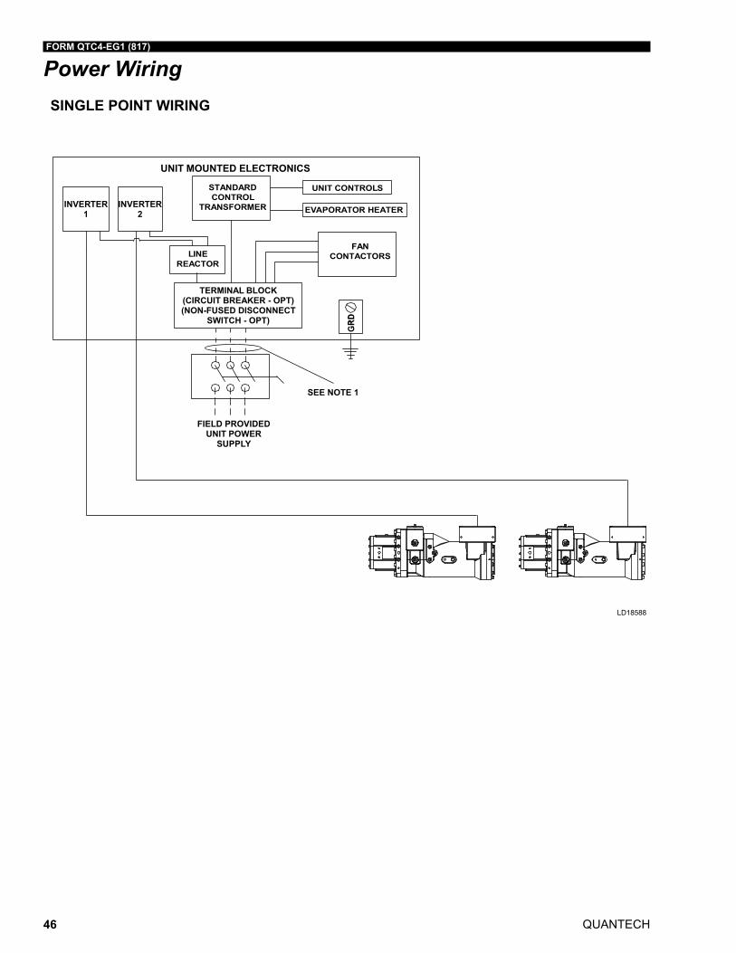
QUANTECH
FORM QTC4-EG1 (817)
46
Power WiringSINGLE POINT WIRING
LD18588
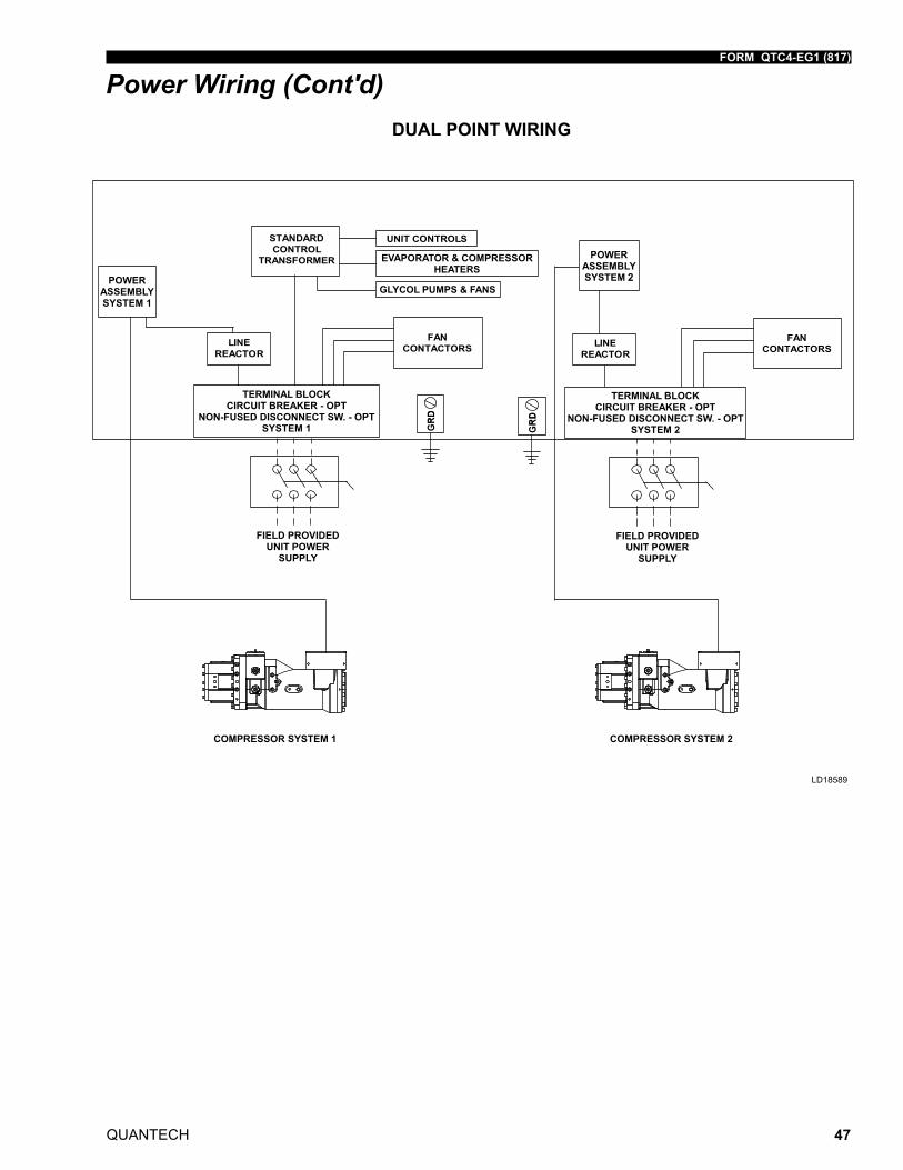
FORM QTC4-EG1 (817)
QUANTECH 47
2
DUAL POINT WIRING
Power Wiring (Cont'd)
LD18589
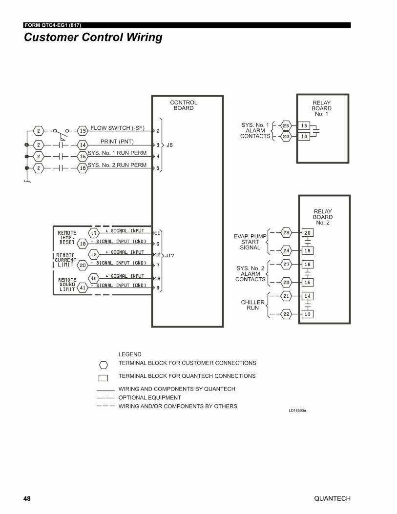
QUANTECH
FORM QTC4-EG1 (817)
48
Customer Control Wiring
SYS. No. 1ALARM
CONTACTS
SYS. No. 2ALARM
CONTACTS
CHILLERRUN
EVAP. PUMPSTARTSIGNAL
SYS. No. 1 RUN PERM
SYS. No. 2 RUN PERM
FLOW SWITCH (-SF)
PRINT (PNT)
LEGENDTERMINAL BLOCK FOR CUSTOMER CONNECTIONS
TERMINAL BLOCK FOR QUANTECH CONNECTIONS
WIRING AND COMPONENTS BY QUANTECHOPTIONAL EQUIPMENTWIRING AND/OR COMPONENTS BY OTHERS
RELAYBOARD
No. 2
RELAYBOARD
No. 1
CONTROLBOARD
LD18590a

FORM QTC4-EG1 (817)
QUANTECH 49
THIS PAGE INTENTIONALLY LEFT BLANK.
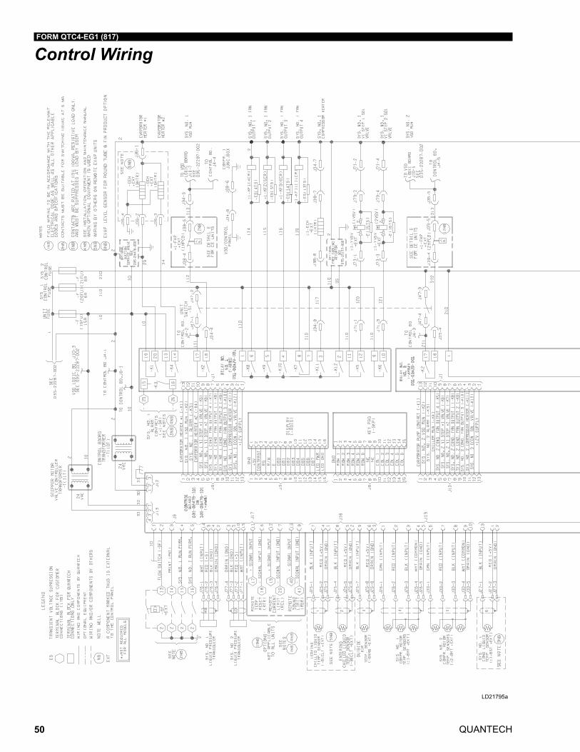
QUANTECH
FORM QTC4-EG1 (817)
50
Control Wiring
LD21795a
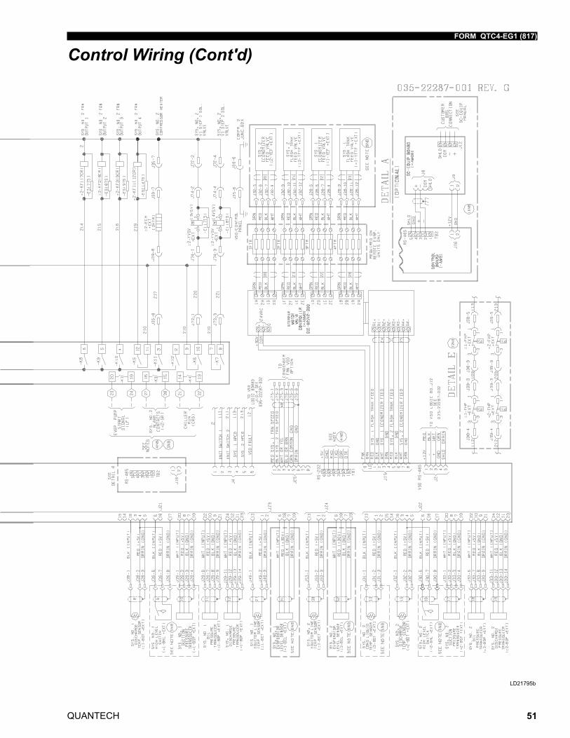
FORM QTC4-EG1 (817)
QUANTECH 51
LD21795a
Control Wiring (Cont'd)
LD21795b
QUANTECH
FORM QTC4-EG1 (817)
52
Guide Specifications
PART 1 - GENERAL
1.01 GENERAL REQUIREMENTS
The requirements of this Section shall conform to the general provisions of the Contract, including General and Supplementary Conditions, Conditions of the Contract, and Con-tract Drawings.
1.02 SCOPE
Provide microprocessor controlled air-cooled twin-screw compressor liquid chillers of the scheduled capacities as shown and indicated on the Drawings, including but not limited to:
1. Chiller package
2. Charge of refrigerant and oil
3. Electrical power and control connections
4. Chilled liquid connections
5. Manufacturer start-up
1.03 QUALITY ASSURANCE
A. ProductsshallbeDesigned,Tested,RatedandCertifiedinaccordancewith,andIn-stalled in compliance with applicable sections of the following Standards and Codes:
1. AHRI 550/590 and 551/591 – Water Chilling Packages Using the Vapor Compres-sion Cycle
2. AHRI 370 – Sound Rating of Large Outdoor Refrigerating and Air-Conditioning Equipment
3. ANSI/ASHRAE 15 – Safety Code for Mechanical Refrigeration
4. ANSI/ASHRAE34–NumberDesignationandSafetyClassificationofRefrigerants
5. ASHRAE 90.1 – Energy Standard for Buildings Except Low-Rise Residential Build-ings
6. ANSI/NFPA 70 – National Electrical Code (N.E.C.)
7. ASME Boiler and Pressure Vessel Code, Section VIII, Division 1
8. OSHA – Occupational Safety and Health Act
9. Manufactured in facility registered to ISO 9001
10. Conform to Intertek Testing Services for construction of chillers and provide ETL/cETL Listed Mark
FORM QTC4-EG1 (817)
QUANTECH 53
B. Factory Run Test: Chiller shall be pressure-tested, evacuated and fully charged with re-frigerantandoil,andshallbefactoryoperationalruntestedwithwaterflowingthroughthe evaporator vessel.
C. Chiller manufacturer shall have a factory-trained and supported service organization.
D. Warranty: Manufacturer shall Warrant all equipment and material of its manufacture against defects in workmanship and/or material for a period of eighteen (18) months from date of shipment or twelve (12) months from date of start-up, whichever occurs first.
1.04 DELIVERY AND HANDLING
A. Unit shall be delivered to job site fully assembled with all interconnecting refrigerant pipingandinternalwiringreadyforfieldinstallationandchargedwithrefrigerantandoil by the Manufacturer.
B. Provide protective covering over vulnerable components for unit protection during shipment. Fit nozzles and open ends with plastic enclosures.
C. Unit shall be stored and handled per Manufacturer’s instructions.
PART 2 - PRODUCTS
2.01 MANUFACTURERS
A. The design shown on the Drawings is based on Quantech QTC4 chiller. Alternate equipment will be acceptable if the manufacturer’s equipment meets the scheduled performanceandcomplieswith these specifications. If equipmentmanufacturedbya manufacturer other than that scheduled is utilized, then the Mechanical Contrac-tor shall be responsible for coordinating with the General Contractor and all affected Subcontractors to insure proper provisions for installation of the furnished unit. This coordination shall include, but not be limited to, the following:
1. Structural supports for units.
2. Piping size and connection/header locations.
3. Electrical power requirements and wire/conduit and overcurrent protection sizes.
4. Chiller physical size on plant layout.
5. Site noise considerations.
B. The Mechanical Contractor shall be responsible for all costs incurred by the General Contractor, Subcontractors, and Consultants to modify the building provisions to ac-cept the furnished alternate equipment.
Guide Specifications (Cont'd)
QUANTECH
FORM QTC4-EG1 (817)
54
2.02 GENERAL
A. Description: Furnish, Install, and Commission factory assembled, charged, and opera-tionalruntestedair-cooledscrewcompressorchillerasspecifiedhereinandshown on the Drawings. Chiller shall include, but is not limited to: a complete system with mul-tiple independent refrigerant circuits, semi hermetic twin screw compressors, shell and tubehybrid falling-filmevaporator,air-cooledcondenser, refrigerant, lubricationsys-tem, interconnecting wiring, safety and operating controls including capacity controller, controlcenter,motorstartingcomponents,andspecialfeaturesasspecifiedhereinorrequired for safe, automatic operation.
B. Operating Characteristics:
1. Provide low and high ambient temperature control options as required to ensure unit is capable of operation from 0°F to 131°F (-18°C to 55°C) ambient temperature.
2. Provide capacity control system capable of reducing unit capacity to 10% of full load for 2 compressor units. Compressor shall start in unloaded condition. Application of factoryinstalledhotgasbypassshallbeacceptableasrequiredtomeetspecifiedminimum load.
C. Cabinet: Unit panels, structural elements, control boxes and heavy gauge structural base shall be constructed of painted, galvanized steel. All exposed sheet steel shall be coated with baked on powder paint to meet 1000-hour salt spray test in accordance with the ASTM B117 standard.
D. Shipping: Unit shall ship in one piece and shall require installer to provide only a single evaporator inlet and outlet pipe connection. If providing chiller model that ships in mul-tiplepieces,bidshallincludeallthematerialandfieldlaborcostsforfactoryauthorizedpersonnel to install a trim kit to connect the pieces as well as all interconnecting piping and wiring.
2.03 COMPRESSORS
A. Compressors: Shall be direct drive, semi hermetic, rotary twin-screw type, including: muffler,temperatureactuated‘off-cycle’heater,rain-tightterminalbox,dischargeshut-off service valve, and precision machined cast iron housing. Design working pressure of entire compressor, suction to discharge, shall be 350 psig (24 barg) or higher. Com-pressor shall be U.L. Recognized.
[OPTIONAL]: A suction shut-off service valve for each compressor.
B. Compressor Motors: Refrigerant suction-gas-cooled accessible hermetic compressor motor,fullsuctiongasflowthrough0.006”(0.1524mm)maximummeshscreen,withinherent internal thermal overload protection and external current overload on all three phases.
C. Balancing Requirements: All rotating parts shall be statically and dynamically balanced.
D. Lubrication System: External oil separators with no moving parts, 450 psig (31 barg) design working pressure, and ETL listed shall be provided on the chiller. Refrigerant systemdifferentialpressureshallprovideoilflowthroughservicereplaceable,0.5mi-cron,full-flow,cartridge-typeoilfilterinternaltocompressor.Filterbypass,lessrestric-tive media, or oil pump not acceptable.
E. Capacity Control: Compressors shall start at minimum load. Microprocessor control shall be provided to match compressor capacity with cooling load.
Guide Specifications (Cont'd)
FORM QTC4-EG1 (817)
QUANTECH 55
2.04 REFRIGERANT CIRCUIT COMPONENTS
A. Refrigerant:ClassifiedasSafetyGroupA1accordingtoASHRAE34
B. Equipment supplied shall comply with LEED Energy & Atmosphere Credit 4, Enhanced Refrigerant Management.
C. Each independent refrigerant circuit shall incorporate all components necessary for the designed operation including: liquid line shut-off valve with charging port, low side pressurereliefdevice,removablecorefilter-drier,andsightglasswithmoistureindica-tor.
D. Chiller manufacturer shall provide an independent circuit for each compressor to pro-vide maximum redundancy during chiller operation. If equipment does not have inde-pendent circuits per compressor, manufacturer shall provide owner one spare com-pressor of each unique size.
E. Discharge lines shall be provided with manually-operated compressor shut-off service valves.
2.05 HEAT EXCHANGERS
A. Evaporator:
1. Evaporator shall be shell and tube, hybrid falling film type to optimize efficiencyandrefrigerantcharge.Tubesshallbehigh-efficiency,internally-andexternally-en-hanced copper tubes with 0.035” (0.89 mm) minimum wall thickness at all interme-diate tube supports to provide maximum tube wall thickness at the support area. Each tube shall be roller expanded into the tube sheets providing a leak proof seal, and be individually replaceable. Independent refrigerant circuits shall be provided per compressor.
[OPTIONAL]: 3 pass arrangement.
2. Constructed, tested, and stamped in accordance with applicable sections of the ASME pressure vessel code for minimum 235 psig (16 barg) refrigerant-side design working pressure and 150 psig (10 barg) liquid-side design working pressure.
3. Water boxes shall be removable to permit tube cleaning and replacement. Water boxes shall include liquid nozzle connections suitable for ANSI/AWWA C-606 cou-plings,welding,orflanges.
[OPTIONAL]: 150 psig (10.3 barg) ANSI raised-face weldable flanges. Flanges are field-welded by Contractor. Companion flanges, bolts, nuts, and gaskets are not included.
[OPTIONAL]: 150 psig (10.3 barg) ANSI raised-face flanges with ANSI/AWWA C-606 couplings. Flanges are field-mounted by Contractor. Companion flanges, bolts, nuts, and gaskets are not included.
[OPTIONAL]: 150 psig (10.3 barg) ANSI raised-face weldable flanges with companion flanges. Flanges are field-welded by Contractor. Bolts, nuts, and gaskets are not included.
[OPTIONAL]: 150 psig (10.3 barg) ANSI raised-face flanges with ANSI/AWWA C-606 couplings with companion flanges. Flanges are field-mounted by Con-tractor. Bolts, nuts, and gaskets are not included.
Guide Specifications (Cont'd)
QUANTECH
FORM QTC4-EG1 (817)
56
4. Provideventanddrainfittings,andthermostatically-controlledheaterstoprotectto0°F (-18°C) ambient temperature in off-cycle.
[OPTIONAL]: A separate power connection for evaporator waterbox heaters is required to assist in freeze protection and shall be provided by the contractor.
5. Connection location: Chilled liquid inlet and outlet nozzle connections are located at rear (opposite control panel) end of unit for the standard two pass arrangement.
[OPTIONAL]: Inlet and outlet nozzle connections located at front end of unit. Available for select configurations.
B. Air-cooled Condenser:
1. Condenser coils shall bemicrochannel type, parallel flow aluminum alloy tubesbrazedasonepiece toenhancedaluminumalloyfins.Condensercoils shall bemade of a single material to avoid galvanic corrosion due to dissimilar metals. Tube-andfin-typecondensercoilsareanacceptablealternatewhentubesandfinsarefabricated of the same metal material to avoid galvanic corrosion due to dissimilar metals. Coils shall be designed for 350 psig (24 barg) or higher working pressure.
[OPTIONAL]: Post-coated, epoxy-dipped condenser microchannel: The unit shall be built with microchannel sections that have been applied with an electro-deposited and baked flexible epoxy coating that is finished with a polyurethane UV resistant top-coat suitable for highly corrosive applications.
[OPTIONAL]: Wire Panels: Heavy gauge, welded wire mesh coated to resist corrosion, to protect condenser coils from incidental damage and also restrict unauthorized access to internal components.
[OPTIONAL]: Louvered Panels (Condenser Coils): Painted steel to match unit panels, over external condenser coil faces.
[OPTIONAL]: Louvered Panels (Full Unit): Painted steel to match unit panels, over internal components.
[OPTIONAL]: Louvered/Wire Panels: Louvered steel panels on external con-denser coil faces, painted to match unit panels. Heavy gauge, welded wire mesh, coated to resist corrosion, around base of machine to restrict unauthor-ized access.
[OPTIONAL]: End Hail Guard: Louvered steel panels on rear of unit (opposite end of control panel), painted to match unit panels.
[OPTIONAL]: V-Guard Panels: Steel panels installed over exposed condenser piping to protect from damage.
2. LowSoundFans:Shallprovideverticalairdischargefromextendedorifices.Fansshallbecomposedofcorrosionresistantaluminumhubandglass-fiber-reinforcedpolypropylene composite blades molded into a low-noise airfoil section. Fan shall be dynamically balanced for vibration-free operation. Fan guards of heavy gauge, PVC coated or galvanized steel.
[OPTIONAL]: Ultra-Quiet Fans
3. FanMotors:High-efficiency,direct-drive,3-phase,insulationclass“F”,currentpro-tected, Totally Enclosed Air-Over (TEAO) motors, with double sealed, permanently-lubricated ball bearings shall be used. Open Drip Proof (ODP) fan motors will not be acceptable.
Guide Specifications (Cont'd)
FORM QTC4-EG1 (817)
QUANTECH 57
2.06 INSULATION
A. Material:Closed-cell,flexible,UVprotected,thermalinsulationcomplyingwithASTMC534Type2(Sheet)forpreformedflexibleelastomericcellularthermalinsulationinsheet and tubular form. The thickness shall be 3/4” (19mm.)
[OPTIONAL]: 1-1/2” (38mm.)
B. Thermal conductivity: 0.26 (BTU/HR-Ft2-°F/in) maximum at 75°F mean temperature.
C. Factory-applied insulation over cold surfaces of liquid chiller components including evaporator shell, water boxes, and suction line. Liquid nozzles shall be insulated by Contractor after pipe installation.
D. Adhesive: As recommended by insulation manufacturer and applied to 100 percent of insulation contact surface including all seams and joints.
2.07 ACOUSTICAL DATA
A. Provide acoustical sound power or sound pressure level data in decibels (dB) at the scheduled eight (8) octave band center frequencies. A-weighted sound data alone is not acceptable.
B. Provide all sound power or sound pressure level data at 100%, 75%, 50%, and 25% load.
C. Supplied equipment shall not exceed scheduled sound power or sound pressure level data at any load point. The mechanical Contractor shall be responsible for any addi-tional costs associated with equipment deviation.
D. Acoustical performance ratings shall be in accordance with AHRI Standard 370
[OPTIONAL]: Provide factory-installed sound reduction enclosures and ultra-quiet fans to meet chiller sound levels scheduled at all load points.
[OPTIONAL]: Provide optional control input to limit sound output of the chiller based on time of day. Shall be programmable at the chiller panel or controlled remotely via signal (4-20mA or 0-10VDC) from BAS system. Chillers without this feature shall be provided with the necessary sound attenuation to meet the scheduled sound performance data at all load points.
2.08 POWER AND ELECTRICAL REQUIREMENTS
A. Power/Control Panel:
1. Factory installed and wired NEMA 3R / IP55, powder painted steel cabinets with tool lockable, hinged, latched, and gasket-sealed outer doors equipped with wind struts for safer servicing. Provide main power connection(s), compressor starters and fan motor contactors, current overloads, and factory wiring.
2. Panel shall include control display access door.
3. Controlcabinetshallbeacloseddesign,withoutrequirementforexternalairflowforcomponent cooling.
Guide Specifications (Cont'd)
QUANTECH
FORM QTC4-EG1 (817)
58
B. Single Point Power:
1. Provide single point power connection to chiller. The power shall be 3 phase of scheduled voltage.
2. Terminal Block connections shall be provided at the point of incoming single point connectionforfieldconnectionandinterconnectingwiringtothecompressors.Sep-arate external protection must be supplied, by others, in the incoming power wiring, which must comply with local codes.
[OPTIONAL]: Single Point Disconnect: A non-fused disconnect and lockable external handle shall be supplied to isolate the unit power voltage for servicing. Separate external fusing must be supplied, by others, in the incoming power wiring which must comply with local codes.
[OPTIONAL]: Single Point Circuit Breaker: A unit-mounted Circuit Breaker with external lockable handle shall be supplied to isolate power voltage for servic-ing. Incoming power wiring must comply with local codes. Circuit breaker shall be sized to provide the motor branch circuit protection, short circuit protection and ground fault protection for the motor branch-circuit conductors, the motor control apparatus and the motors.
C. Control Transformer: Power panel shall be supplied with a factory mounted and wired control transformer that will supply all unit control voltage from the main unit power supply. Transformer shall utilize scheduled line voltage on the primary side and provide 115V/1Ø on secondary.
D. Short Circuit Withstand Rating of the chiller electrical enclosure shall be (380, 400, & 460V: minimum of 30,000 Amps [OR 65,000 Amps for Single Point Circuit Breaker]).Rating shall be published in accordance with UL508.
E. Motor Starters: Motor starters shall be zero electrical inrush current (Variable Frequen-cy Drives) or reduced inrush type (Closed transition Wye-Delta or Solid State) for mini-mum electrical inrush. Open transition Wye-Delta and Across the Line type starters will not be acceptable.
F. Power Factor:
1. Provide equipment with power factor correction capacitors as required to maintain a displacement power factor of 95% at all load conditions.
2. The installing contractor is responsible for additional cost to furnish and install pow-er factor correction capacitors if they are not factory mounted and wired.
G. All exposed power wiring shall be routed through liquid-tight, UV-stabilized, non-me-tallic conduit.
H. Supplied equipment shall not exceed scheduled Minimum Circuit Ampacity (MCA). The mechanical Contractor shall be responsible for any additional costs associated with equipment deviation.
Guide Specifications (Cont'd)
FORM QTC4-EG1 (817)
QUANTECH 59
2.09 CONTROLS
A. General:
1. Provide automatic control of chiller operation including compressor start/stop and load/unload, anti-recycle timers, condenser fans, evaporator pump, evaporator heater, unit alarm contacts and run signal contacts.
2. Chiller shall automatically reset to normal chiller operation after power failure.
3. Unit operating software shall be stored in non-volatile memory. Field programmed set points shall be retained in lithium-battery-backed regulated time clock (RTC) memory for minimum 5 years.
4. Alarm contacts shall be provided to provide a remote alert for any unit or system safety fault.
B. Display and Keypad:
1. Provide minimum 80 character liquid crystal display that is both viewable in direct sunlight and has LED backlighting for nighttime viewing. Provide one keypad and display panel per chiller.
2. Display and keypad shall be accessible through display access door without open-ing main control/electrical cabinet doors.
3. Display shall provide a minimum of unit setpoints, status, electrical data, tempera-ture data, pressures, safety lockouts and diagnostics without the use of a coded display.
4. Descriptions in English (or available language options), numeric data in English (or Metric) units.
5. Sealed keypad shall include unit On/Off switch.
C. Programmable Setpoints (within Manufacturer limits): Display language, chilled liquid cooling mode, local/remote control mode, display units mode, system lead/lag control mode, remote temperature reset, remote current limit, remote sound limit, low ambient temperature cutout enable/disable, leaving chilled liquid setpoint and range, maximum remote temperature reset.
D. Display Data: Chilled liquid leaving and entering temperatures; outside ambient air temperature; lead system; evaporator pump status; active remote control; compressor suction, discharge, and oil pressures per refrigerant circuit; compressor discharge, mo-tor, and oil temperatures per refrigerant circuit; saturation temperatures per refrigerant circuit; compressor speed; condenser fan status; condenser subcooling temperature; condenser drain valve percentage open; compressor capacity in percentage of Full Load Amps; compressor number of starts; run time; operating hours; evaporator heater status; history data for last ten shutdown faults; history data for last 20 normal (non-fault) shutdowns.
E. Predictive Control Points: Unit controls shall avoid safety shutdown when operating outside design conditions by optimizing the chiller controls and cooling load output to stay online and avoid safety limits being reached. The system shall monitor the follow-ing parameters and maintain the maximum cooling output possible without shutdown of the equipment: motor current, suction pressure, discharge pressure, starter internal ambient temperature, and starter baseplate temperature.
Guide Specifications (Cont'd)
QUANTECH
FORM QTC4-EG1 (817)
60
F. System Safeties: Shall cause individual compressor systems to perform auto-reset shut down if: high discharge pressure or temperature, low suction pressure, low motor current, high/low differential oil pressure, low discharge superheat, high motor tem-perature, system control voltage.
G. Unit Safeties: Shall be automatic reset and cause compressors to shut down if: high orlowambienttemperature,lowleavingchilledliquidtemperature,undervoltage,flowswitchoperation.Contractorshallprovideflowswitchandwiringperchillermanufac-turer requirements.
H. Manufacturer shall provide any controls not listed above, necessary for automatic chilleroperation.MechanicalContractorshallprovidefieldcontrolwiringnecessarytointerface sensors to the chiller control system.
2.10 ACCESSORIES AND OPTIONS
Some accessories and options supersede standard product features. All options are fac-tory-mounted unless otherwise noted.
A. CONTROLS OPTIONS:
1. Building Automation System Interface: Chiller to accept 4 to 20mA or 0 to 10 VDC input from BAS (by others) to reset the leaving chilled liquid temperature or load limit setpoint or both.
2. Gateway: Provides communication for Building Automation Systems, including BACnet (MS/TP), Modbus, N2, and LON. (Field Commissioned by BAS Manufac-turer)
3. ThermalStorage:Providespecialcontrollogicandmodificationstoproduceleavingchilled brine temperatures below 40°F (4.4°C.)
B. GENERAL OPTIONS:
1. Flow Switch: Vapor proof SPDT, NEMA 3R switch, 150 psig (10.3 barg), -20°F to 250°F (-28.9°C to 121.1°C.) (Field Mounted by Contractor)
2. Differential Pressure Switch: 3-45 psig (0.2-3 barg) range with 1/4” NPTE pressure connections. (Field Mounted by Contractor)
3. Chicago Code Relief Valve – Special relief valves per Chicago Code
4. Special Requirement Documents:
a. Special Requirement Document Package (SRDP) includes Pressure Vessel Report, Unit Run Test Report, Production System Check Sheet and Final Unit Inspection Check Sheet.
b. Materials Package includes steel mill material reports for vessels in addition to Pressure Vessel Report, Unit Run Test Report, Production System Check Sheet and Final Unit Inspection Check Sheet.
Guide Specifications (Cont'd)
FORM QTC4-EG1 (817)
QUANTECH 61
5. Vibration Isolation (All Options Field Mounted by Contractor):
a. Elastomeric Isolators.
b. 1” Deflection Spring Isolators: Level adjustable, spring and cage type isolators for mounting under the unit base rails.
c. 2” Deflection Restrained Spring Isolators: Level adjustable, restrained mounts in rugged welded steel housing with vertical and horizontal limit stops. Housings shall be designed to withstand a minimum 1.0g accelerated force in all direc-tions to 2” (50.8 mm.)
PART 3 - EXECUTION
3.01 INSTALLATION
A. General: Rig and Install in full accordance with Manufacturer’s requirements, Project drawings, and Contract documents.
B. Location: Locate chiller as indicated on drawings, including cleaning and service main-tenance clearance per Manufacturer instructions. Adjust and level chiller on support structure.
C. Components: Installing Contractor shall provide and install all auxiliary devices and accessories for fully operational chiller.
D. Electrical: Coordinate electrical requirements and connections for all power feeds with Electrical Contractor.
E. Controls: Coordinate all control requirements and connections with Controls Contractor.
F. Finish:InstallingContractorshallpaintdamagedandabradedfactoryfinishwithtouch-uppaintmatchingfactoryfinish.
Guide Specifications (Cont'd)

Printed on recycled paperForm QTC4-EG1 (817) Supersedes: QTC4-EG1 (217) © 2017 P.O. Box 423, Milwaukee, WI 53201 Printed in USAIssued on 8/11//2017