Embed Size (px)
Citation preview
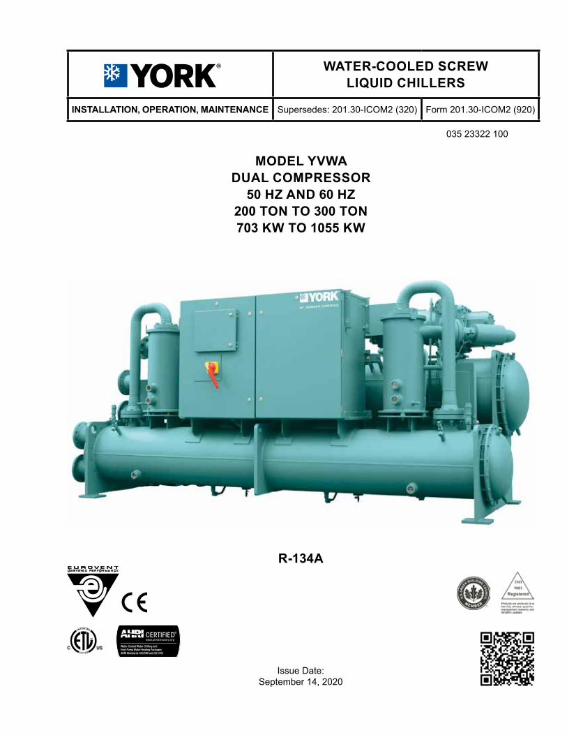
MODEL YVWADUAL COMPRESSOR
50 HZ AND 60 HZ 200 TON TO 300 TON703 KW TO 1055 KW
R-134A
Issue Date: September 14, 2020
035 23322 100
WATER-COOLED SCREW LIQUID CHILLERS
INSTALLATION, OPERATION, MAINTENANCE Supersedes: 201.30-ICOM2 (320) Form 201.30-ICOM2 (920)
JOHNSON CONTROLS2
FORM 201.30-ICOM2ISSUE DATE: 09/14/2020
This equipment is a relatively complicated apparatus. During rigging, installation, operation, maintenance, or service, individuals may be exposed to certain com-ponents or conditions including, but not limited to: heavy objects, refrigerants, materials under pressure, rotating components, and both high and low voltage. Each of these items has the potential, if misused or handled improperly, to cause bodily injury or death. It is the obligation and responsibility of rigging, instal-lation, and operating/service personnel to identify and recognize these inherent hazards, protect themselves, and proceed safely in completing their tasks. Failure to comply with any of these requirements could result in serious damage to the equipment and the property in
IMPORTANT!READ BEFORE PROCEEDING!
GENERAL SAFETY GUIDELINES
which it is situated, as well as severe personal injury or death to themselves and people at the site.
This document is intended for use by owner-authorized rigging, installation, and operating/service personnel. It is expected that these individuals possess independent training that will enable them to perform their assigned tasks properly and safely. It is essential that, prior to performing any task on this equipment, this individual shall have read and understood the on-product labels, this document and any referenced materials. This in-dividual shall also be familiar with and comply with all applicable industry and governmental standards and regulations pertaining to the task in question.
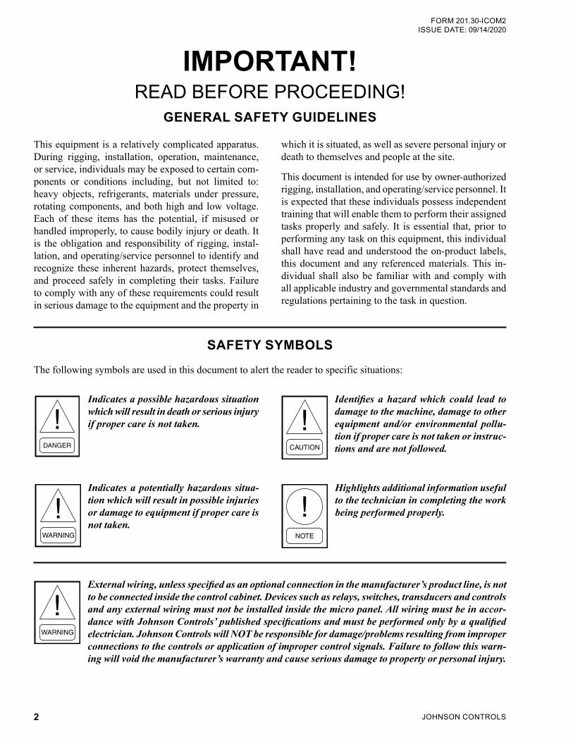
SAFETY SYMBOLS
The following symbols are used in this document to alert the reader to specific situations:
Indicates a possible hazardous situation which will result in death or serious injury if proper care is not taken.
Indicates a potentially hazardous situa-tion which will result in possible injuries or damage to equipment if proper care is not taken.
Identifies a hazard which could lead to damage to the machine, damage to other equipment and/or environmental pollu-tion if proper care is not taken or instruc-tions and are not followed.
Highlights additional information useful to the technician in completing the work being performed properly.
External wiring, unless specified as an optional connection in the manufacturer’s product line, is not to be connected inside the control cabinet. Devices such as relays, switches, transducers and controls and any external wiring must not be installed inside the micro panel. All wiring must be in accor-dance with Johnson Controls’ published specifications and must be performed only by a qualified electrician. Johnson Controls will NOT be responsible for damage/problems resulting from improper connections to the controls or application of improper control signals. Failure to follow this warn-ing will void the manufacturer’s warranty and cause serious damage to property or personal injury.
JOHNSON CONTROLS 3
FORM 201.30-ICOM2 ISSUE DATE: 09/14/2020
ASSOCIATED LITERATURE
MANUAL DESCRIPTION FORM NUMBER
YVWA Chiller Installation Checklist 201.30-CL1
YVWA Chiller Start-up Checklist and Request for Authorized Start-up Technician 201.30-CL2
Field Connections and Control Wiring for YVWA Chiller 201.30-PW2
YVWA Renewal Parts 201.30-RP1
Limited Warranty 50.05-NM2
Shipping Damage Claims 50.15-NM
Long-Term Storage Periodic Checklist and Logs for YR, YS, and YVWA Screw Chillers 50.20-CL9
AFFECTED PAGES DESCRIPTION
3 Conditioned Based Maintenance program information added
91 Native communication updated to future Native BAS
CHANGEABILITY OF THIS DOCUMENT
In complying with Johnson Controls’ policy for con-tinuous product improvement, the information con-tained in this document is subject to change without notice. Johnson Controls makes no commitment to update or provide current information automatically to the manual or product owner. Updated manuals, if applicable, can be obtained by contacting the nearest Johnson Controls Service office or accessing the John-son Controls Knowledge Exchange website at https://docs.johnsoncontrols.com/chillers/.
It is the responsibility of rigging, lifting, and operating/ service personnel to verify the applicability of these documents to the equipment. If there is any question regarding the applicability of these documents, rig-ging, lifting, and operating/service personnel should verify whether the equipment has been modified and if current literature is available from the owner of the equipment prior to performing any work on the chiller.
REVISION NOTES
Revisions made to this document are indicated in the following table. These revisions are to technical information, and any other changes in spelling, grammar, or formatting are not included.
CONDITIONED BASED MAINTENANCE
Traditional chiller maintenance is based upon assumed and generalized conditions. In lieu of the traditional maintenance program, a Johnson Controls YORK Conditioned Based Maintenance (CBM) program can be substituted. This CBM service plan is built around the specific needs for the chiller, operating conditions, and annualized impact realized by the chiller. Your lo-cal Johnson Controls Branch can propose a customized
Planned Service Agreement that leverages real time and historical data, delivering performance reporting, corrective actions required and data enabled guidance for optimal operation and lifecycle assurance. The pro-gram will include fault detection diagnostics, operation code statistics, performance based algorithms and ad-vance rules based rationale delivered by the Johnson Controls Connected Equipment Portal.
JOHNSON CONTROLS4
FORM 201.30-ICOM2ISSUE DATE: 09/14/2020
LD29437
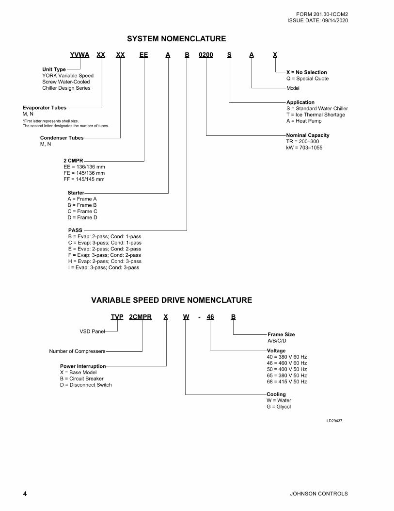
SYSTEM NOMENCLATURE
Unit TypeYORK Variable Speed Screw Water-CooledChiller Design Series
2 CMPREE = 136/136 mmFE = 145/136 mmFF = 145/145 mm
Evaporator TubesM, N
X = No SelectionQ = Special Quote
StarterA = Frame AB = Frame BC = Frame CD = Frame D
ApplicationS = Standard Water ChillerT = Ice Thermal ShortageA = Heat Pump
Model
YVWA XX EE A 0200 A XB S
Nominal CapacityTR = 200–300kW = 703–1055
PASSB = Evap: 2-pass; Cond: 1-passC = Evap: 3-pass; Cond: 1-passE = Evap: 2-pass; Cond: 2-passF = Evap: 3-pass; Cond: 2-passH = Evap: 2-pass; Cond: 3-passI = Evap: 3-pass; Cond: 3-pass
*First letter represents shell size. The second letter designates the number of tubes.
VARIABLE SPEED DRIVE NOMENCLATURE
VSD Panel
Power InterruptionX = Base ModelB = Circuit BreakerD = Disconnect Switch
Number of Compressers
TVP X W B46
Frame SizeA/B/C/D
CoolingW = WaterG = Glycol
2CMPR
Voltage40 = 380 V 60 Hz46 = 460 V 60 Hz50 = 400 V 50 Hz65 = 380 V 50 Hz68 = 415 V 50 Hz
-
XX
Condenser TubesM, N
JOHNSON CONTROLS 5
FORM 201.30-ICOM2 ISSUE DATE: 09/14/2020
TABLE OF CONTENTS
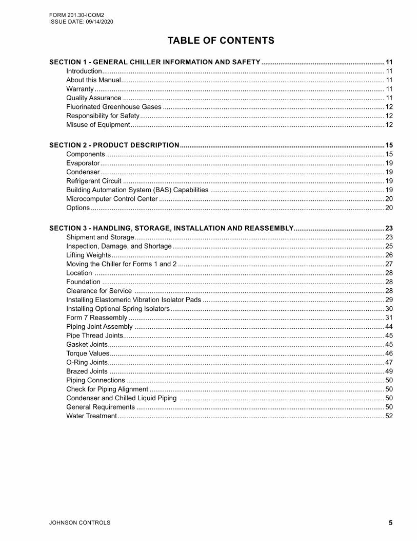
SECTION 1 - GENERAL CHILLER INFORMATION AND SAFETY ................................................................. 11Introduction ..................................................................................................................................................... 11About this Manual ........................................................................................................................................... 11Warranty ......................................................................................................................................................... 11Quality Assurance .......................................................................................................................................... 11Fluorinated Greenhouse Gases .....................................................................................................................12Responsibility for Safety .................................................................................................................................12Misuse of Equipment ......................................................................................................................................12
SECTION 2 - PRODUCT DESCRIPTION ............................................................................................................15Components ...................................................................................................................................................15Evaporator ......................................................................................................................................................19Condenser ......................................................................................................................................................19Refrigerant Circuit ..........................................................................................................................................19Building Automation System (BAS) Capabilities ............................................................................................19Microcomputer Control Center .......................................................................................................................20Options ...........................................................................................................................................................20
SECTION 3 - HANDLING, STORAGE, INSTALLATION AND REASSEMBLY ................................................23Shipment and Storage ....................................................................................................................................23Inspection, Damage, and Shortage ................................................................................................................25Lifting Weights ................................................................................................................................................26Moving the Chiller for Forms 1 and 2 .............................................................................................................27Location .........................................................................................................................................................28Foundation .....................................................................................................................................................28Clearance for Service ....................................................................................................................................28Installing Elastomeric Vibration Isolator Pads ................................................................................................29Installing Optional Spring Isolators .................................................................................................................30Form 7 Reassembly .......................................................................................................................................31Piping Joint Assembly ....................................................................................................................................44Pipe Thread Joints..........................................................................................................................................45Gasket Joints ..................................................................................................................................................45Torque Values .................................................................................................................................................46O-Ring Joints ..................................................................................................................................................47Brazed Joints .................................................................................................................................................49Piping Connections ........................................................................................................................................50Check for Piping Alignment ............................................................................................................................50Condenser and Chilled Liquid Piping ............................................................................................................50General Requirements ...................................................................................................................................50Water Treatment .............................................................................................................................................52
JOHNSON CONTROLS6
FORM 201.30-ICOM2ISSUE DATE: 09/14/2020
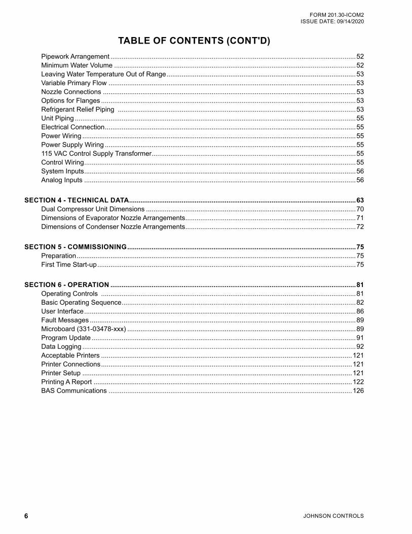
TABLE OF CONTENTS (CONT'D)Pipework Arrangement ...................................................................................................................................52Minimum Water Volume .................................................................................................................................52Leaving Water Temperature Out of Range .....................................................................................................53Variable Primary Flow ....................................................................................................................................53Nozzle Connections .......................................................................................................................................53Options for Flanges ........................................................................................................................................53Refrigerant Relief Piping ...............................................................................................................................53Unit Piping ......................................................................................................................................................55Electrical Connection ......................................................................................................................................55Power Wiring ..................................................................................................................................................55Power Supply Wiring ......................................................................................................................................55115 VAC Control Supply Transformer .............................................................................................................55Control Wiring .................................................................................................................................................55System Inputs .................................................................................................................................................56Analog Inputs .................................................................................................................................................56
SECTION 4 - TECHNICAL DATA .........................................................................................................................63Dual Compressor Unit Dimensions ................................................................................................................70Dimensions of Evaporator Nozzle Arrangements ...........................................................................................71Dimensions of Condenser Nozzle Arrangements ...........................................................................................72
SECTION 5 - COMMISSIONING ..........................................................................................................................75Preparation .....................................................................................................................................................75First Time Start-up ..........................................................................................................................................75
SECTION 6 - OPERATION ...................................................................................................................................81Operating Controls ........................................................................................................................................81Basic Operating Sequence .............................................................................................................................82User Interface .................................................................................................................................................86Fault Messages ..............................................................................................................................................89Microboard (331-03478-xxx) ..........................................................................................................................89Program Update .............................................................................................................................................91Data Logging ..................................................................................................................................................92Acceptable Printers ......................................................................................................................................121Printer Connections ......................................................................................................................................121Printer Setup ................................................................................................................................................121Printing A Report ..........................................................................................................................................122BAS Communications ..................................................................................................................................126
JOHNSON CONTROLS 7
FORM 201.30-ICOM2 ISSUE DATE: 09/14/2020
TABLE OF CONTENTS (CONT'D)SECTION 7 - MAINTENANCE ...........................................................................................................................129
General Requirements .................................................................................................................................129Daily Operating Inspections .........................................................................................................................130Compressor Oil ............................................................................................................................................130Replacing the Oil Filter .................................................................................................................................133Refrigerant Charging ....................................................................................................................................135Handling Refrigerant for Dismantling and Repairs .......................................................................................135Checking System for Leaks ..........................................................................................................................136Refrigerant Leak Checking ...........................................................................................................................136Pressure Connections ..................................................................................................................................136Testing for Evaporator and Condenser Tube Leaks .....................................................................................137Evacuation and Dehydration of Unit .............................................................................................................137Condensers and Evaporators Maintenance .................................................................................................140Cleaning Evaporator and Condenser Tubes ................................................................................................140Compressor Maintenance ............................................................................................................................142Electrical Controls ........................................................................................................................................142
SECTION 8 - TROUBLESHOOTING .................................................................................................................143Abnormal Operation, Analysis and Correction .............................................................................................143Troubleshooting the Compressor and Oil Separation System .....................................................................143
SECTION 9 - DECOMMISSIONING, DISMANTLING, AND DISPOSAL ........................................................149
JOHNSON CONTROLS8
FORM 201.30-ICOM2ISSUE DATE: 09/14/2020
LIST OF FIGURESFIGURE 1 - Emergency Shutdown Handle ............................................................................................................13FIGURE 2 - YVWA Chiller Major Components (Front View) ...................................................................................16FIGURE 3 - YVWA Chiller Major Components (Rear View) ...................................................................................17FIGURE 4 - Basic System Control and VSD System Architecture .........................................................................18FIGURE 5 - Control Center User Interface .............................................................................................................20FIGURE 6 - Head Pressure Control System ..........................................................................................................22FIGURE 7 - Unit Rigging for Forms 1 and 2 ...........................................................................................................27FIGURE 8 - Service Clearance Requirements .......................................................................................................28FIGURE 9 - Elastomeric Vibration Isolator Pad Mounts (Standard), in. (mm) ........................................................29FIGURE 10 - Spring Isolators (Optional), in. (mm) .................................................................................................30FIGURE 11 - Rigging the Evaporator .....................................................................................................................32FIGURE 12 - Condenser Rigging ...........................................................................................................................33FIGURE 13 - Isolator Installation ............................................................................................................................34FIGURE 14 - Heat Exchanger Shipping Brackets ..................................................................................................35FIGURE 15 - Heat Exchanger Pipes ......................................................................................................................35FIGURE 16 - Liquid Injection Piping .......................................................................................................................36FIGURE 17 - Filter Drier and Piping ......................................................................................................................36FIGURE 18 - Driveline (Compressor/Motor) Assemblies ........................................................................................37FIGURE 19 - Oil Separators ...................................................................................................................................38FIGURE 20 - Mufflers Installation ...........................................................................................................................39FIGURE 21 - Oil Separator Discharge Piping .........................................................................................................40FIGURE 22 - Transducer, Eductor and Oil Return Piping ......................................................................................41FIGURE 23 - Oil Supply Piping ...............................................................................................................................41FIGURE 24 - Piping to Compressor .......................................................................................................................42FIGURE 25 - Variable Speed Drive (VSD) .............................................................................................................43FIGURE 26 - VSD Cooling Hoses .........................................................................................................................44FIGURE 27 - Torque Pattern ..................................................................................................................................45FIGURE 28 - Adjustable End Fitting .......................................................................................................................47FIGURE 29 - Back Off Locknut ...............................................................................................................................47FIGURE 30 - Screw Fitting Into Port .......................................................................................................................47FIGURE 31 - Torque Fitting ....................................................................................................................................47FIGURE 32 - Sae Straight Thread O-Ring Port ......................................................................................................48FIGURE 33 - Brazed Joints ....................................................................................................................................49FIGURE 34 - Schematic of a Typical Piping Arrangement .....................................................................................52FIGURE 35 - Leaving Water Temperature Out-of-Range Suggested Layout ........................................................53FIGURE 36 - Grooved Nozzle ................................................................................................................................53FIGURE 37 - Flange Attachment ............................................................................................................................53FIGURE 38 - Typical Components of Relief Piping ................................................................................................54FIGURE 39 - Power Connections ...........................................................................................................................60FIGURE 40 - Compressor Unit Dimensions ...........................................................................................................70FIGURE 41 - Evaporators - Compact Water Boxes (2-Pass) .................................................................................71FIGURE 42 - Evaporators - Compact Water Boxes (3-Pass) .................................................................................71FIGURE 43 - Condensers - Compact Water Boxes (1-Pass) .................................................................................72FIGURE 44 - Condensers - Compact Water Boxes (2-Pass) .................................................................................72FIGURE 45 - Condensers - Compact Water Boxes (3-Pass) .................................................................................72FIGURE 46 - Keypad and Display ..........................................................................................................................81FIGURE 47 - Control Operation ..............................................................................................................................83FIGURE 48 - Status Key .........................................................................................................................................87FIGURE 49 - New 331-03478-xxx Microboard .......................................................................................................90FIGURE 50 - Unit Data Key ..................................................................................................................................102FIGURE 51 - System Data Keys (1-2) ..................................................................................................................103FIGURE 52 - VSD Data and Operating Hours/Start Counter Keys ......................................................................105FIGURE 53 - History Key ......................................................................................................................................106FIGURE 54 - Setpoints Key ..................................................................................................................................108FIGURE 55 - Setpoint High and Low Limits Defined By Control Range (CR) ......................................................109
JOHNSON CONTROLS 9
FORM 201.30-ICOM2 ISSUE DATE: 09/14/2020
LIST OF FIGURES (CONT'D)FIGURE 56 - Program Key ................................................................................................................................... 110FIGURE 57 - Options Key .................................................................................................................................... 116FIGURE 58 - Date/Time and Schedule Key ......................................................................................................... 118FIGURE 59 - Manual Override and Print Key .......................................................................................................120FIGURE 60 - Printer Cable Connection From YVWA Chiller to a Computer .......................................................120FIGURE 61 - Printer Cable Connection From YVWA Chiller to a Serial Printer ...................................................121FIGURE 62 - Sample Printout ..............................................................................................................................123FIGURE 63 - System Switches and Service Keys ................................................................................................125FIGURE 64 - E-Link Gateway Option ...................................................................................................................126FIGURE 65 - Charging Oil ...................................................................................................................................132FIGURE 66 - Oil Filter Assembly ..........................................................................................................................133FIGURE 67 - Oil Eductor Assembly ......................................................................................................................134FIGURE 68 - Motor Windings Diagram ................................................................................................................135FIGURE 69 - Saturation Curve .............................................................................................................................139
JOHNSON CONTROLS10
FORM 201.30-ICOM2ISSUE DATE: 09/14/2020
LIST OF TABLESTABLE 1 - Unit Weight ...........................................................................................................................................26TABLE 2 - Service Clearance Requirments ...........................................................................................................28TABLE 3 - Evaporator Dimensions, in. (mm) .........................................................................................................32TABLE 4 - Condenser Dimensions, in. (mm) .........................................................................................................33TABLE 5 - Compressor Weight and Dimensions ...................................................................................................37TABLE 6 - Oil Separator Weight and Dimensions ..................................................................................................38TABLE 7 - VSD Weight and Dimensions ................................................................................................................43TABLE 8 - Assembly Compounds ..........................................................................................................................44TABLE 9 - ANSI 150 LB Flange Torque Specifications ..........................................................................................46TABLE 10 - ANSI 300 LB Flange Torque Specifications ........................................................................................46TABLE 11 - SAE J429 Gr 5 Bolts Torque Specifications ........................................................................................46TABLE 12 - O-Ring Assembly Torque Specifications .............................................................................................48TABLE 13 - Brazed Joints ......................................................................................................................................49TABLE 14 - Water Volume for Applications ............................................................................................................52TABLE 15 - Evaporator and Condenser Water Capacity (lb/kg) and Volume GAL (l) ...........................................52TABLE 16 - Refrigerant Relief Characteristics (Per Valve) ....................................................................................54TABLE 17 - System Input Connections ..................................................................................................................56TABLE 18 - Lug Data (UL/ASME/CE) - Pin 22/Power Field ...................................................................................61TABLE 19 - Voltage Variations ..............................................................................................................................62TABLE 20 - Complete Pin Number Description .....................................................................................................63TABLE 21 - Evaporator Nozzle Dimensions, in. (mm) ...........................................................................................71TABLE 22 - Condenser Nozzle Dimensions, in. (mm) ...........................................................................................72TABLE 23 - Water Flow Rate Limits, GPM (L/s) (Based on Standard Tubes at Design Full Load Conditions) .....73TABLE 24 - Load Limiting Values ...........................................................................................................................84TABLE 25 - Flash Card Update Error XXXXX ........................................................................................................91TABLE 26 - Data Logging ......................................................................................................................................92TABLE 27 - Unit Warnings......................................................................................................................................93TABLE 28 - Unit Safeties (Faults) ..........................................................................................................................95TABLE 29 - System Safeties (Faults) .....................................................................................................................97TABLE 30 - Sensor Minimum/Maximum Outputs .................................................................................................104TABLE 31 - Setpoint Values .................................................................................................................................109TABLE 32 - Program Limits .................................................................................................................................. 111TABLE 33 - Setup Mode Programmable .............................................................................................................. 114TABLE 34 - OKIDATA OKIPOS 441 .....................................................................................................................121TABLE 35 - Printout Types ...................................................................................................................................122TABLE 36 - Real Time Number Errors .................................................................................................................127TABLE 37 - Operation/Inspection/Maintenance Requirements for YVWA Chillers ..............................................129TABLE 38 - Compressor Oil Limits .......................................................................................................................131TABLE 39 - System Pressures .............................................................................................................................138TABLE 40 - Troubleshooting Guide ......................................................................................................................144TABLE 41 - 3K Temperature Sensor ....................................................................................................................146TABLE 42 - 3K Temperature Sensor - Evaporator Refrigerant and Eductor Temperature Sensor ......................146TABLE 43 - Pressure Transducer .........................................................................................................................147TABLE 44 - Metric Conversion .............................................................................................................................150
JOHNSON CONTROLS 11
FORM 201.30-ICOM2 ISSUE DATE: 09/14/2020
1SECTION 1 - GENERAL CHILLER INFORMATION AND SAFETY
INTRODUCTIONYORK YVWA chillers are manufactured to the highest design and construction standards to ensure high per-formance, reliability and adaptability to all types of air conditioning installations.
The unit is intended for cooling water or glycol solu-tions, and is not suitable for purposes other than those specified in this manual.
ABOUT THIS MANUALThis manual and any other document supplied with the unit are the property of Johnson Controls which re-serves all rights. This manual may not be reproduced, in whole or in part, without prior written authorization from an authorized Johnson Controls representative.
In addition, this manual:
• Includes suggested best working practices and procedures, which are issued for guidance only, and they do not take precedence over the above stated individual responsibility and/or local safety regulations.
• Contains all the information required for correct installation and commissioning of the unit, to-gether with operating and maintenance instruc-tions.
• Should be read thoroughly before attempting to operate or service the unit.
• Contains detailed procedures, including installa-tion, commissioning and maintenance tasks that must only be performed by suitably trained and qualified personnel.
The manufacturer will not be liable for any injury or damage caused by incorrect installation, commission-ing, operation or maintenance resulting from a failure to follow the procedures and instructions detailed in the manual.
WARRANTYJohnson Controls warrants YVWA chillers in accor-dance with the Limited Warranty Engineered Systems Equipment procedure. Refer to Limited Warranty (Form 50.05-NM2).
Johnson Controls warrants all equipment and materi-als against defects in workmanship and materials for a period of 18 months from the date of shipment or 12 months from the date of start-up, whichever comes first, unless labor or extended warranty has been pur-chased as part of the contract.
The warranty is limited to parts only replacement and shipping of any faulty part, or subassembly, which has failed due to defects in workmanship and materials. All claims must be supported by evidence that the fail-ure has occurred within the warranty period, and that the unit was operated within the designed parameters specified.
All warranty claims must specify the unit model, serial number, order number, and run hours/starts. Model and serial number information is printed on the unit identi-fication plate.
The unit warranty will be void if any modification to the unit is carried out without prior written approval from Johnson Controls. For warranty purposes, the fol-lowing conditions must be satisfied:
• The initial start of the unit must be carried out by trained personnel from an authorized Johnson Controls Field Service Office.
• Only genuine YORK approved spare parts, oils, coolants, and refrigerants must be used.
• All of the scheduled maintenance operations de-tailed in this manual must be performed at the specified times by suitably trained and qualified personnel.
• Failure to satisfy any of these conditions will au-tomatically void the warranty. Refer to Limited Warranty (Form 50.05-NM2) for complete details.
QUALITY ASSURANCEUnits conform with the following European Directives:
• Equipment Directive (2006/42/EC)
• EMC Directive (2004/108/EC)
• Pressure Equipment Directive (97/23/EC)
• Low Voltage Directive (2006/95/EC)
• Safety Code for Mechanical Refrigeration (EN378-2 (2008))
JOHNSON CONTROLS12
FORM 201.30-ICOM2ISSUE DATE: 09/14/2020SECTION 1 - GENERAL CHILLER INFORMATION AND SAFETY
• AHRI 550/590 and 551/591 - Water Chilling Packages using the Vapor Compression Cycle.
• GB/T 18430.1 - Water Chilling (Heat Pump) Pack-ages Using The Vapor Compression Cycle - Part 1: Water Chilling (Heat Pump) Packages For In-dustrial & Commercial And Similar Applications.
• GB25131 - Safety Requirements For Water Chill-ers (Heat Pump) Using The Vapor Compression Cycle.
• GB150/151 - Steel Pressure Vessels/Tubular Heat Exchangers.
• ANSI/ASHRAE 34 - Number Designation And Safety Classification Of Refrigerants.
• ASHRAE 90.1 - Energy Standard For Buildings Except Low-Rise Residential Buildings.
• Machinery Directive (2006/42/EC)
• EMC Directive (2004/108/EC)
• Pressure Equipment Directive (97/23/EC)
• Safety Code for Mechanical Refrigeration (EN 378-2)
• Safety of machinery - Electrical Equipment of Machine (EN 60204-1)
• Manufactured in an EN ISO 9001 accredited or-ganization
• ISO 9614 – Determination of sound power levels of noise sources using sound intensity
• Conform to CE Testing Services for construction of chillers and provide CE Listed Mark
FLUORINATED GREENHOUSE GASES• This equipment contains fluorinated greenhouse
gases covered by the Kyoto Protocol.
• The global warming potential of the refrigerant (R-134a) used in this unit is 1300. The refrigerant quantity is stated in this document.
• The fluorinated greenhouse gases in this equipment may not be vented to the atmosphere.
RESPONSIBILITY FOR SAFETYEvery care has been taken in the design and manufac-ture of the unit to ensure compliance with the safety requirements. However, the individual operating or working on any equipment is primarily responsible for:
• Personal safety, the safety of other personnel, and the equipment.
• Correct utilization of the equipment in accordance with the procedures detailed in the manual.
MISUSE OF EQUIPMENT
Suitability For ApplicationThe unit is intended for cooling water or glycol so-lutions and is not suitable for purposes other than those specified in these instructions. Any use of the equipment other than its intended use, or operation of the equipment contrary to the relevant procedures may result in injury to the operator, or damage to the equipment. The unit must not be operated outside the design parameters specified in this manual.
Brine ApplicationsWhen the chiller is not running, cold brine should NOT be run through the evaporator. However, if there is brine running through the evaporator, there must be flow through the condenser to prevent tubes from freezing.
Structural SupportStructural support of the unit must be provided as in-dicated in these instructions. Failure to provide proper support may result in injury to the operator, or damage to the equipment and/or building.
Mechanical Strength The unit is not designed to withstand loads or stresses from adjacent equipment, pipework, or structures. Ad-ditional components must not be mounted on the unit. Any such extraneous loads may cause structural failure and may result in injury to the operator, or damage to the equipment.
General AccessThere are a number of areas and features, which may be a hazard and potentially cause injury when working on the unit unless suitable safety precautions are taken. Make sure access to the unit is restricted to suitably qualified personnel, who are familiar with the potential hazards and precautions necessary for safe operation and maintenance of equipment containing high tem-peratures, pressures, and voltages.
JOHNSON CONTROLS 13
SECTION 1 - GENERAL CHILLER INFORMATION AND SAFETYFORM 201.30-ICOM2 ISSUE DATE: 09/14/2020
1Pressure SystemsThe unit contains refrigerant vapor and liquid under pres-sure, release of which can be a danger and cause injury. The user should make sure that care is taken during in-stallation, operation, and maintenance to avoid damage to the pressure system. No attempt should be made to gain access to the component parts of the pressure system other than by suitably trained and qualified personnel.
ElectricalThe unit must be grounded. No installation or main-tenance work should be attempted on the electrical equipment without first switching the power off, iso-lating and locking-off the power supply. Servicing and maintenance on live equipment must not be attempted. No attempt should be made to gain access to the con-trol panel or electrical enclosures during normal opera-tion of the unit.
Components may also have sharp edges. Reasonable care should be taken when working in contact with any components to avoid risk of minor abrasions and lac-erations.
Refrigerants and OilsRefrigerants and oils used in the unit are generally non-toxic, non-flammable, and non-corrosive, and pose no special safety hazards. Use of gloves and safety glasses is recommended when working on the unit. The build-up of refrigerant vapor, from a leak for example, does pose a risk of asphyxiation in confined or enclosed spaces and attention should be given to good ventila-tion.
High Temperature and Pressure CleaningHigh temperature and pressure cleaning methods (for example, steam cleaning) should not be used on any part of the pressure system as this may cause operation of the pressure relief devices. Detergents and solvents, which may cause corrosion, should also be avoided.
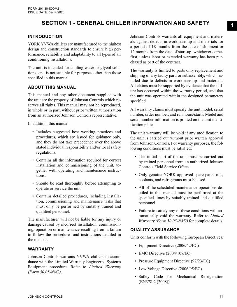
Emergency Shutdown (Optional)In case of emergency, the unit can be stopped from the control panel if it is fitted with the optional circuit breaker (red and yellow as shown below) or non-fused disconnect switch.
Safety Labels
For safe operation, read the instructions first.
Warning: This machine may start auto-matically without prior warning.
Warning: Hot surface.
Warning: Safety relief valve may dis-charge gas or liquid without prior warning.
Warning: Isolate all electrical sources of supply before opening or removing the cover, as lethal voltages may exist.
General attention symbol.
Warning: On isolating the supply it may take up to 300 seconds for the capacitor voltage to fall below 50 volts.
FIGURE 1 - EMERGENCY SHUTDOWN HANDLE

JOHNSON CONTROLS14
FORM 201.30-ICOM2ISSUE DATE: 09/14/2020
THIS PAGE INTENTIONALLY LEFT BLANK.
JOHNSON CONTROLS 15
FORM 201.30-ICOM2 ISSUE DATE: 09/14/2020
2
SECTION 2 - PRODUCT DESCRIPTION
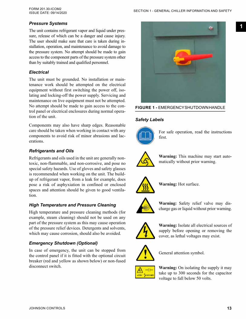
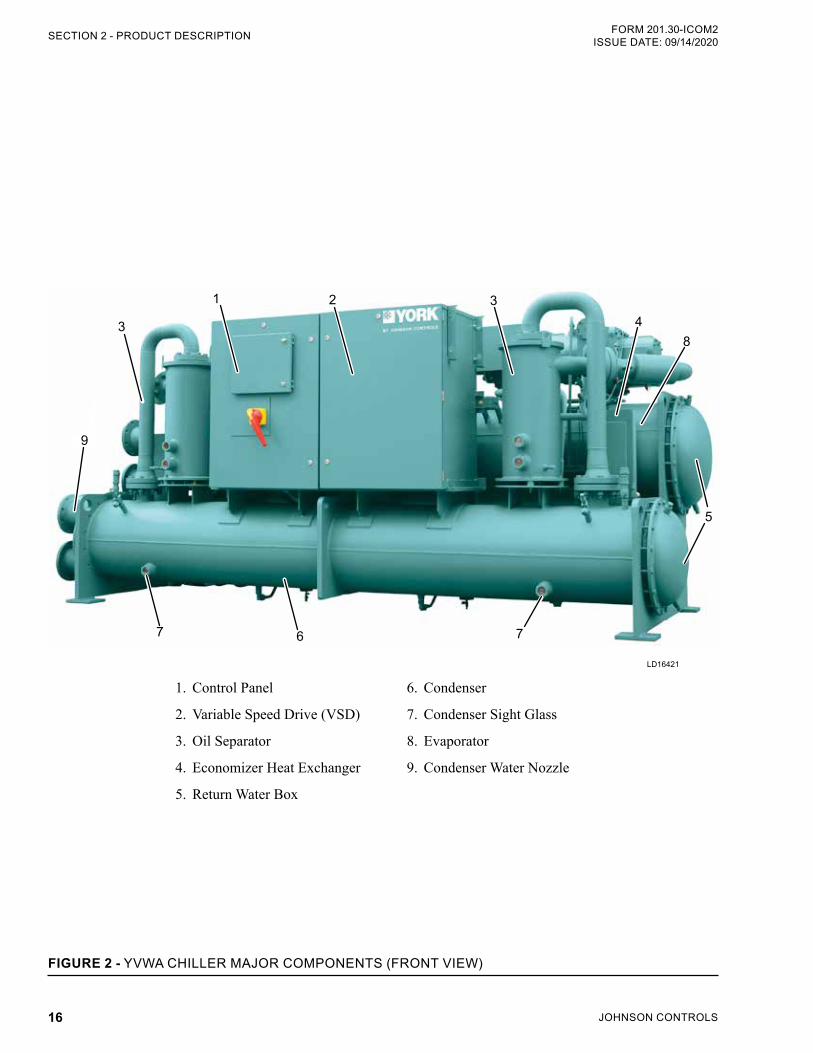
COMPONENTSThe YVWA chiller, as shown in Figure 2 page 16, and Figure 3 on page 17, consists of:
• Two screw compressors with mufflers
• A hybrid falling film evaporator
• A water-cooled condenser
• Two economizer heat exchangers
• Two oil separators
• VSD with control panel
Oil separators use no moving parts, and are rated for 388 psig (2.68 MPa) design pressure. Oil cooling is accomplished by refrigerant leaving the eductor flash-ing in the suction line, which cools the oil, motor, and compressor.
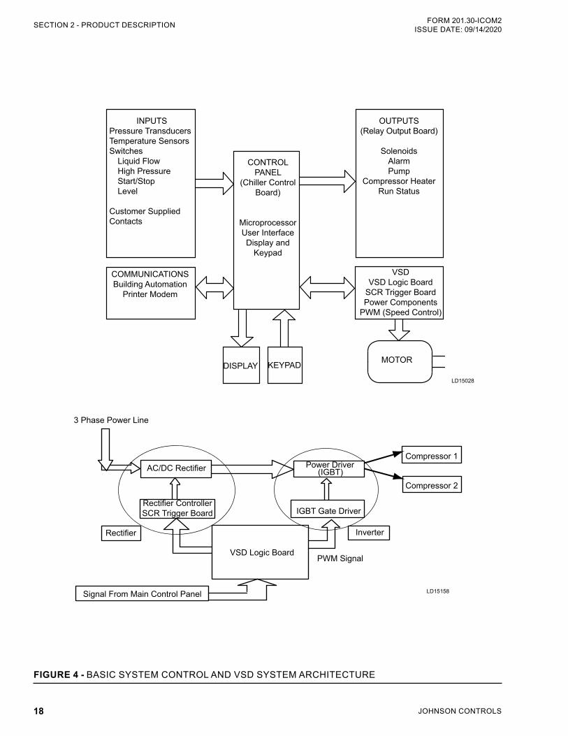
An integral liquid cooled, transistorized, pulse-width modulated (PWM) VSD is controlled by the micropro-cessor control panel to start/stop, select compressors to run, and select compressor speed. Power factor is 95% at part or full load.
The chiller microprocessor communicates with the VSD logic board via a 3-wire RS-485 opto-coupled data link. The VSD logic board runs one or both com-pressors to the speed requested by the chiller micro-processor to meet the load as shown in Figure 4 on page 17.
YORK YVWA chillers are designed for water or gly-col cooling. All units are designed to be located in an equipment room unless the unit was ordered specially for outside applications.
The units are completely assembled with all intercon-necting refrigerant piping and internal wiring, ready for field installation.
Before delivery, the unit is:
• Pressure tested
• Evacuated
• Fully charged with refrigerant and oil in each in-dependent refrigerant circuit
All exposed power wiring is routed through liquid-tight, non-metallic conduit.
The YVWA chiller combines the modern screw com-pressor design with the latest Variable Speed Drive (VSD) technology. The VSD enables the compressor speed to match the system load, and provides soft starts with no electrical inrush. The lack of heat buildup on start-up also reduces required off time between starts to two minutes.
JOHNSON CONTROLS16
FORM 201.30-ICOM2ISSUE DATE: 09/14/2020SECTION 2 - PRODUCT DESCRIPTION
FIGURE 2 - YVWA CHILLER MAJOR COMPONENTS (FRONT VIEW)
LD16421
1 2
3
3
67 7
5
4
1. Control Panel
2. Variable Speed Drive (VSD)
3. Oil Separator
4. Economizer Heat Exchanger
5. Return Water Box
6. Condenser
7. Condenser Sight Glass
8. Evaporator
9. Condenser Water Nozzle
8
9
JOHNSON CONTROLS 17
SECTION 2 - PRODUCT DESCRIPTIONFORM 201.30-ICOM2 ISSUE DATE: 09/14/2020
2
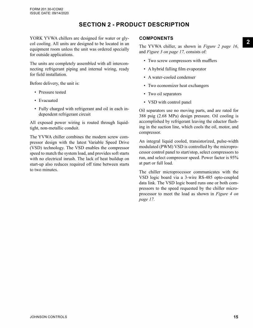
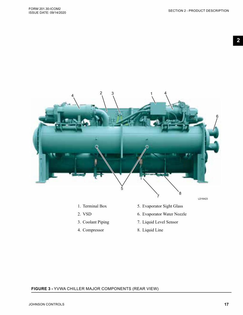
FIGURE 3 - YVWA CHILLER MAJOR COMPONENTS (REAR VIEW)
LD16423
34 1 4
5
78
1. Terminal Box
2. VSD
3. Coolant Piping
4. Compressor
5. Evaporator Sight Glass
6. Evaporator Water Nozzle
7. Liquid Level Sensor
8. Liquid Line
6
2
JOHNSON CONTROLS18
FORM 201.30-ICOM2ISSUE DATE: 09/14/2020SECTION 2 - PRODUCT DESCRIPTION
LD15028
INPUTSPressure TransducersTemperature SensorsSwitches
Liquid FlowHigh PressureStart/StopLevel
Customer SuppliedContacts
CONTROLPANEL
(Chiller ControlBoard)
MicroprocessorUser InterfaceDisplay and
Keypad
DISPLAY KEYPAD MOTOR
OUTPUTS(Relay Output Board)
SolenoidsAlarmPump
Compressor HeaterRun Status
VSDVSD Logic Board
SCR Trigger BoardPower Components
PWM (Speed Control)
COMMUNICATIONSBuilding Automation
Printer Modem
FIGURE 4 - BASIC SYSTEM CONTROL AND VSD SYSTEM ARCHITECTURE
LD15158
3 Phase Power Line
AC/DC Rectifier Power Driver
IGBT Gate Driver
VSD Logic Board
Inverter
PWM Signal
Signal From Main Control Panel
Rectifier
Compressor 1
Compressor 2
Rectifier Controller SCR Trigger Board
(IGBT)
JOHNSON CONTROLS 19
SECTION 2 - PRODUCT DESCRIPTIONFORM 201.30-ICOM2 ISSUE DATE: 09/14/2020
2
COMPRESSORS
The direct-drive, semi-hermetic rotary screw com-pressor incorporates advanced technology in a rugged design. The continuous function, microprocessor con-trolled VSD provides smooth capacity control from 100% down to 20% chiller capacity. State-of-the-art screw compressor design and manufacturing ensures optimal efficiencies at all chiller load points. With no unloading steps or slide valves in the compressor, the YVWA variable speed driven compressor has 50% fewer moving parts than fixed speed compressors with slide valves. The YVWA compressor is one of the most efficient and reliable screw compressors in the industry.
EVAPORATORThe evaporator is a shell and tube, hybrid falling film heat exchanger, which contains a balance of flooded and falling film technology to optimize efficiency, minimize refrigerant charge, and maintain reliable con-trol. A distribution system provides uniform refrigerant flow for optimum performance.
CONDENSERThe condenser is a shell and tube type, equipped with:
• Discharge gas baffle used to deflect the refriger-ant gas from the tubes, and distribute the refriger-ant gas flow properly.
• Integral subcoolers, located at the bottom of the condenser shell, provide highly effective liquid refrigerant subcooling to provide the highest cy-cle efficiency.
• Refrigerant relief valves set at 388 psig (26.8 MPa) for 3/4 in. tubes and 340 psig (2.34 MPa) for 1 in. tubes.
• Removable steel waterboxes that:• Have design working pressure of 150 psig
(10.3 kPa). • Are tested at 225 psig (15.5 kPa). • Contain welded steel water baffles. • Have welded stub-out water nozzle connec-
tions with ANSI/AWWA C-606 grooves, and are capped for shipment.
• Have plugged 3/4 in. (19 mm) drain and vent connections provided in each waterbox.
REFRIGERANT CIRCUITAn independent refrigerant circuit is provided for each compressor. The refrigerant circuits use steel pipe. In addition, each of the refrigerant circuits has:
• An oil separator, with no moving parts, and de-signed for minimum oil carryover, mounted in the discharge line of the compressor.
• An economizer heat exchanger is located in the refrigerant circuit to improve refrigeration effect in the evaporator for increased chiller efficiency.
ELECTRICAL
Incoming single point power is standard, utilizing:
• Lockable circuit breaker, terminal block, or non-fused disconnect
• 115 VAC control transformer
• VSD with control panel
Standard design includes powder painted steel cabinet with hinged, latched, and gasket sealed outer doors, equipped with wind struts for safer servicing. All ex-posed wiring is routed through a liquid-tight, UV sta-bilized, non-metallic conduit.
BUILDING AUTOMATION SYSTEM (BAS) CAPABILITIESThe E-Link Gateway provides a versatile connection between chiller equipment and open/standard proto-cols.
• Efficiently manages the communication protocols currently used by YORK equipment, exposing the data in a consistent, organized, and defined fash-ion.
• The E-Link communication board is available as a factory installed option.
• The board must be field commissioned to ensure communication protocol.
• Refer to Communication Protocol Mapping docu-ment for communication points.
JOHNSON CONTROLS20
FORM 201.30-ICOM2ISSUE DATE: 09/14/2020SECTION 2 - PRODUCT DESCRIPTION
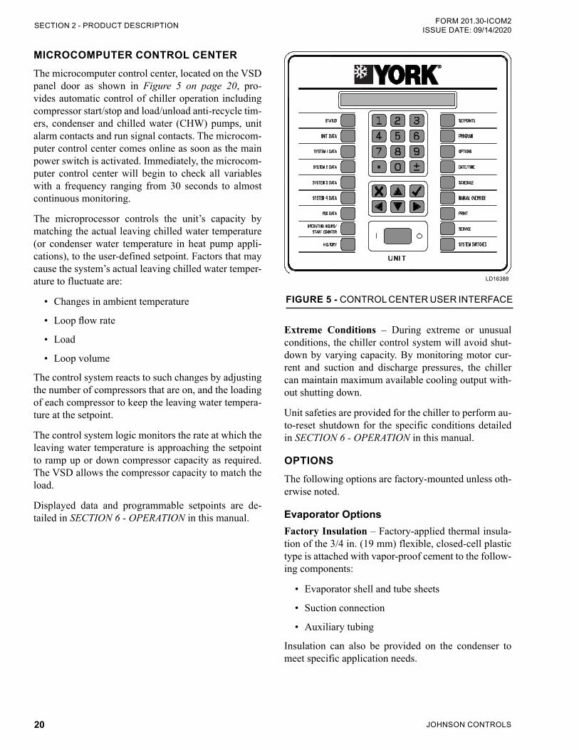
MICROCOMPUTER CONTROL CENTERThe microcomputer control center, located on the VSD panel door as shown in Figure 5 on page 20, pro-vides automatic control of chiller operation including compressor start/stop and load/unload anti-recycle tim-ers, condenser and chilled water (CHW) pumps, unit alarm contacts and run signal contacts. The microcom-puter control center comes online as soon as the main power switch is activated. Immediately, the microcom-puter control center will begin to check all variables with a frequency ranging from 30 seconds to almost continuous monitoring.
The microprocessor controls the unit’s capacity by matching the actual leaving chilled water temperature (or condenser water temperature in heat pump appli-cations), to the user-defined setpoint. Factors that may cause the system’s actual leaving chilled water temper-ature to fluctuate are:
• Changes in ambient temperature
• Loop flow rate
• Load
• Loop volume
The control system reacts to such changes by adjusting the number of compressors that are on, and the loading of each compressor to keep the leaving water tempera-ture at the setpoint.
The control system logic monitors the rate at which the leaving water temperature is approaching the setpoint to ramp up or down compressor capacity as required. The VSD allows the compressor capacity to match the load.
Displayed data and programmable setpoints are de-tailed in SECTION 6 - OPERATION in this manual.
LD19539
FIGURE 5 - CONTROL CENTER USER INTERFACE
LD16388
Extreme Conditions – During extreme or unusual conditions, the chiller control system will avoid shut-down by varying capacity. By monitoring motor cur-rent and suction and discharge pressures, the chiller can maintain maximum available cooling output with-out shutting down.
Unit safeties are provided for the chiller to perform au-to-reset shutdown for the specific conditions detailed in SECTION 6 - OPERATION in this manual.
OPTIONSThe following options are factory-mounted unless oth-erwise noted.
Evaporator OptionsFactory Insulation – Factory-applied thermal insula-tion of the 3/4 in. (19 mm) flexible, closed-cell plastic type is attached with vapor-proof cement to the follow-ing components:
• Evaporator shell and tube sheets
• Suction connection
• Auxiliary tubing
Insulation can also be provided on the condenser to meet specific application needs.
JOHNSON CONTROLS 21
SECTION 2 - PRODUCT DESCRIPTIONFORM 201.30-ICOM2 ISSUE DATE: 09/14/2020
2
Double Thick Insulation – Double thick 1-1/2 in. (38 mm) insulation on the evaporator is used for glycol cooling.
Controls OptionsBAS Temperature Reset is a factory-installed option to accept a 4 mA to 20 mA or a 0 VDC to 10 VDC input. This option allows remote reset of the Leaving Chilled Liquid Temperature Setpoint (LCHLTS). The setpoint can be positively offset up to 40°F (22.2°C). This option is useful for ice storage or process applica-tions, or for periods where higher chilled liquid tem-peratures are adequate for low loads, which is available alone or in combination with the BAS load limit.
BAS Load Limit is a factory-installed option that ac-cepts a 4 mA to 20 mA or a 0 VDC to 10 VDC in-put. This option allows remote reset of the load limit setpoint, which can limit system demand from 30-100%, which is available alone, or in combination, with the BAS temperature reset.
E-Link Gateway option provides communication or BAS, including BACnet® (MS/TP), Modbus®, LON, and N2 between the control panel and the BAS.
General OptionsFlow Switch Accessory Switch
NEMA 3R switch, 150 psig (10.3 kPA) DWP, -20°F to 250°F (-29°C to 121°C) with 1 in. NPT (IPS) connec-tion for upright mounting in horizontal pipe. This flow switch (or equivalent) must be furnished with each unit for chilled liquid loop. The condenser liquid flow switch is optional. (Field mounted)
Differential Pressure Switch
This 3 psig to 45 psig (0.2 kPa to 3 kPa) range switch, with 1/4 in. NPTE pressure connections, is an alterna-tive to the paddle-type flow switch. (Field mounted)
Relief Valves The following types of relief valves are used to quickly relieve excess pressure of the refrigerant charge to the atmosphere:
• Dual Pressure Relief Valve – Two safety relief valves are mounted in parallel; one valve is al-ways operational to assist in valve replacement during maintenance.
Electrical IsolationCircuit Breaker – A unit-mounted circuit breaker with external lockable handle will be supplied to isolate the single point power voltage for servicing. Circuit break-er is sized to provide motor branch, short circuit and ground fault protection for the motor branch-circuit conductors and control apparatus, and the motors.
Non-Fused Disconnect Switch – Unit-mounted dis-connect switch with external lockable handle can be supplied to isolate the unit power voltage for servicing. Separate external fusing must be supplied by the power wiring, which must comply with local codes.
Optional Special Requirement Documents
Special Requirement Document Package (SRDP) may include:
• Pressure vessel report
• Production system and final unit inspection check sheets
• Steel mill material reports for vessels
• Unit run test report
• Final unit/component inspection
• Hydro, vacuum, and pneumatic tests
• Electrical safety
Vibration IsolationElastomeric Isolators – Recommended for normal in-stallations. (Field mounted)
Spring Isolators, 1 in. (25.4 mm) – To support the unit, spring isolators are level adjustable spring and cage isolators for mounting under the unit base rails. The nominal deflection may vary slightly by applica-tion. (Field mounted)
Refrigerant Isolation Valves
Optional, factory-installed isolation valves in the com-pressor discharge lines and refrigerant liquid line per circuit are available. The valves allow isolation and storage of the refrigerant charge in the chiller condens-er during servicing, which eliminate time-consuming transfers to remote storage vessels. Both valves in each independent refrigerant circuit are positive shut-off, as-suring integrity of the storage system.
JOHNSON CONTROLS22
FORM 201.30-ICOM2ISSUE DATE: 3/29/2018
Head Pressure ControlApplicable to software version Y.WCS.31.05 or Y.WCS.41.05, and later.)
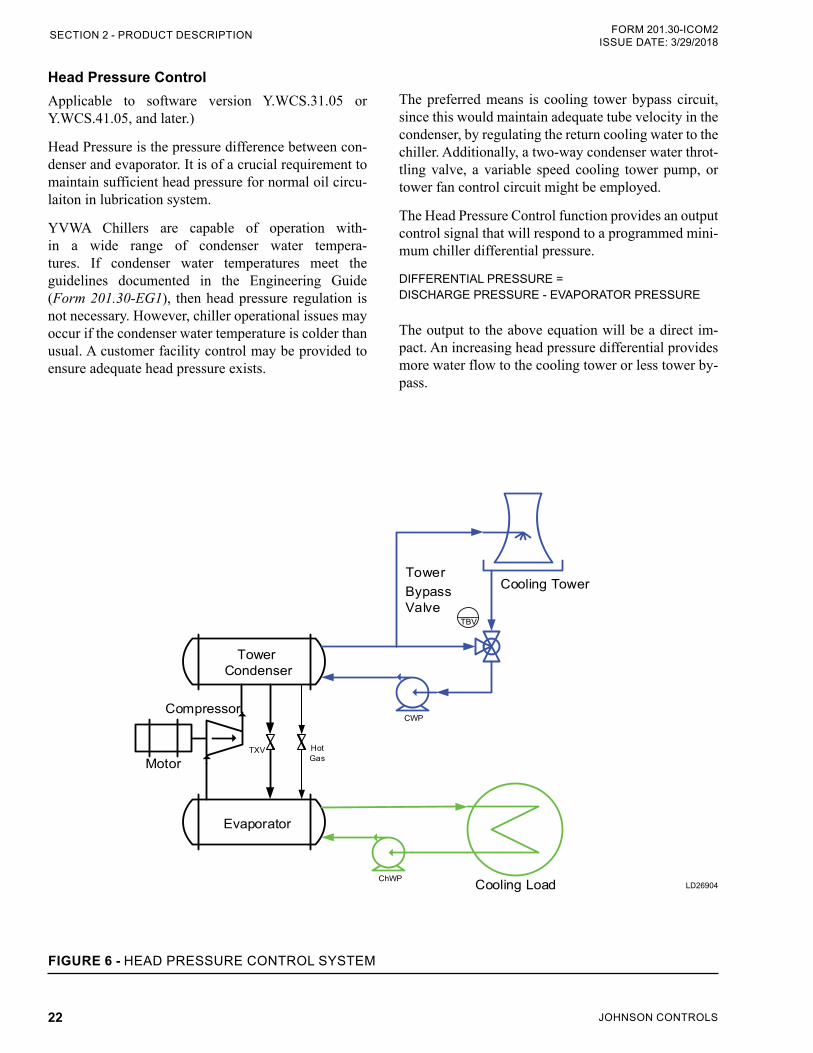
Head Pressure is the pressure difference between con-denser and evaporator. It is of a crucial requirement to maintain sufficient head pressure for normal oil circu-laiton in lubrication system.
YVWA Chillers are capable of operation with-in a wide range of condenser water tempera-tures. If condenser water temperatures meet the guidelines documented in the Engineering Guide (Form 201.30-EG1), then head pressure regulation is not necessary. However, chiller operational issues may occur if the condenser water temperature is colder than usual. A customer facility control may be provided to ensure adequate head pressure exists.
The preferred means is cooling tower bypass circuit, since this would maintain adequate tube velocity in the condenser, by regulating the return cooling water to the chiller. Additionally, a two-way condenser water throt-tling valve, a variable speed cooling tower pump, or tower fan control circuit might be employed.
The Head Pressure Control function provides an output control signal that will respond to a programmed mini-mum chiller differential pressure.
DIFFERENTIAL PRESSURE = DISCHARGE PRESSURE - EVAPORATOR PRESSURE The output to the above equation will be a direct im-pact. An increasing head pressure differential provides more water flow to the cooling tower or less tower by-pass.
FIGURE 6 - HEAD PRESSURE CONTROL SYSTEM
LD26904
Tower Condenser
Evaporator
Compressor
TXV
ChWP
MotorHotGas
Cooling Load
CWP
Cooling TowerTowerBypass Valve
TBV
SECTION 2 - PRODUCT DESCRIPTION
JOHNSON CONTROLS 23
FORM 201.30-ICOM2 ISSUE DATE: 09/14/2020
3
Observe the following precautions:
• Notify the nearest Johnson Controls office in am-ple time for a Johnson Controls representative to supervise rigging the unit to its operating position and the assembly of its components. Refer to the YVWA Installation Checklist (Form 201.30-CL1) for detailed instructions. Do not dismantle or un-wrap the chiller for any reason unless under the supervision of a Johnson Controls representative.
• Do not make final power supply connections to the compressor motor drive or control center.
• Do not open valves or connections under any cir-cumstances.
• Do not charge the unit with refrigerant.
• Do not attempt to start the system.
• Do not run hot water (110°F/43°C max) or steam through the evaporator or condenser at any time.
SHIPMENT AND STORAGETo ensure consistent quality and maximum reliability, all units are tested and inspected before leaving the fac-tory. The chiller may be ordered and shipped in any of the following forms:
• Form 1 (shipped assembled with refrigerant charge)
• Form 2 (shipped assembled without refrigerant charge)
• Form 7 (shipped in split assemblies without re-frigerant)
• Miscellaneous loose items are shipped with all forms.
When shipping a Form 2 or Form 7 unit, make arrangements with the nearest Johnson Controls Field Service Office to make sure the refrigerant is on-site when the unit is ready to be charged.
SECTION 3 - HANDLING, STORAGE, INSTALLATION AND REASSEMBLY
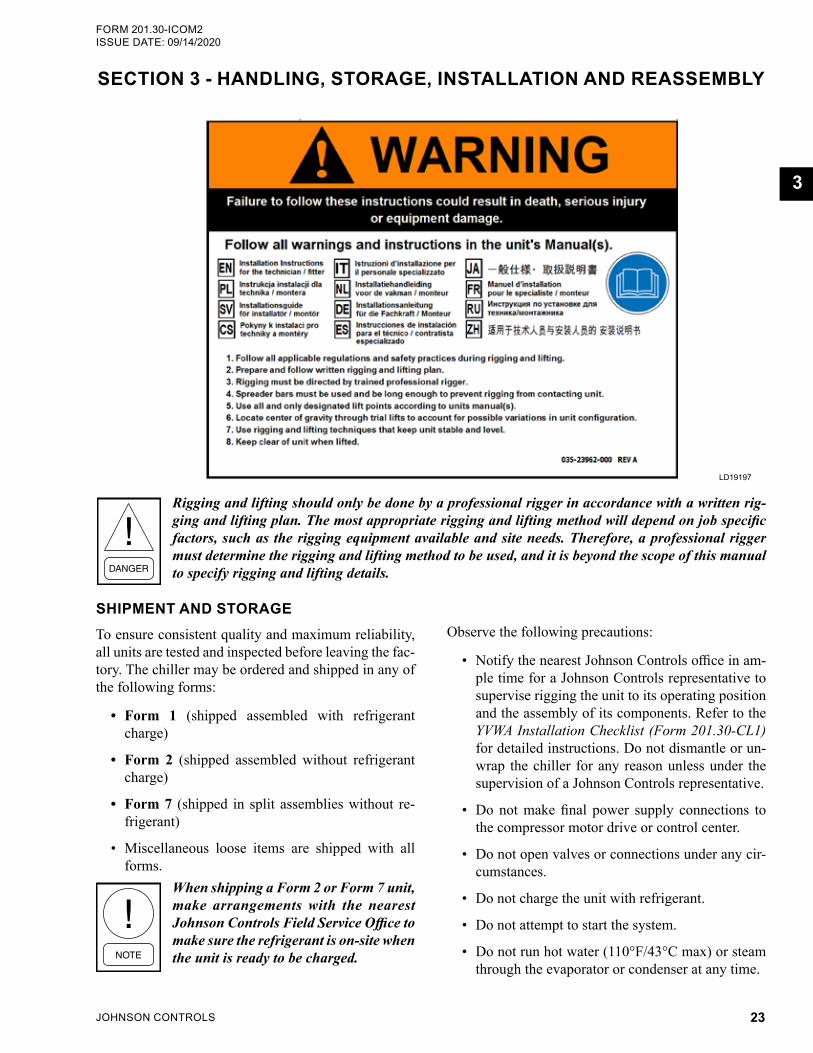
Rigging and lifting should only be done by a professional rigger in accordance with a written rig-ging and lifting plan. The most appropriate rigging and lifting method will depend on job specific factors, such as the rigging equipment available and site needs. Therefore, a professional rigger must determine the rigging and lifting method to be used, and it is beyond the scope of this manual to specify rigging and lifting details.
LD19197
JOHNSON CONTROLS24
FORM 201.30-ICOM2ISSUE DATE: 09/14/2020SECTION 3 - HANDLING, STORAGE, INSTALLATION AND REASSEMBLY
Chiller Unit (Form 1)The unit is completely assembled at the factory.
• The driveline (compressor/motor assembly) is mounted and all the necessary interconnecting piping is assembled.
• The complete unit is factory leak-tested, evacuat-ed, and shipped charged with R-134a refrigerant.
• The Variable Speed Drive (VSD) is mounted, wired, and shipped with glycol.
Miscellaneous ItemsThe following items are shipped together:
• Four vibration isolation pads (or optional spring isolators and brackets)
• VSD inhibitor
• Other shipped loose items, including piping, wa-ter temperature controls, wiring, etc.
Chiller Unit (Form 2)The unit is completely assembled at the factory.
• The driveline (compressor/motor assembly) is mounted and all the necessary interconnecting piping is assembled.
• The complete unit is factory leak-tested, evacu-ated, and shipped without R-134a refrigerant.
• The VSD is mounted, wired, and shipped with glycol.
Miscellaneous ItemsThe following items are shipped together:
• Four vibration isolation pads (or optional spring isolators and brackets)
• VSD inhibitor
• Other shipped loose items, including piping, wa-ter temperature controls, wiring, etc.
Chiller Unit (Form 7)The unit is factory assembled, refrigerant piped, wired and leak tested and then dismantled for shipment. The close-coupled compressor/motor assembly and VSD is removed from the shells and skidded separately.
Form 7 YVWA chillers are shipped in the following as-semblies:
1. Two drivelines (compressor/motor assembly)
2. Evaporator
3. Condenser
4. Variable Speed Drive (VSD) with Control Panel
5. Two oil separators
6. Two muffler kits
7. Two discharge piping kits
8. Loose piping and wiring harnesses
9. Miscellaneoues items
Protective covering is furnished on the drivelines, control center, VSD, and unit-mounted controls. Wa-ter nozzles are capped with fitted plastic enclosures. All Form 7 components are protected with industrial-grade, reinforced shrink-wrapped covering and shipped in split assemblies without refrigerant charge.
Refrigerant charges are shipped separately. Arrangements with the local Johnson Controls Field Service Office must be made to make sure refrigerant is on-site when the unit is ready to be charged.
Two DrivelinesThe drivelines (compressor/motor assembly) are re-moved from shells and skidded.
• Motor Terminal Box and all integral wiring is left on the compressor.
• All openings on the compressor are closed and shipped charged with a 2 psig to 3 psig (115 kPa to 122 kPa) holding charge of dry nitrogen.
JOHNSON CONTROLS 25
SECTION 3 - HANDLING, STORAGE, INSTALLATION AND REASSEMBLYFORM 201.30-ICOM2 ISSUE DATE: 09/14/2020
3
ShellsThe evaporator and condenser are split apart at the tube sheets, and prepared for shipping separately.
• All conduit is removed from the shells.
• All wiring harnesses on the shells are removed.
• Refrigerant lines between the shells are flanged and capped, requiring no welding.
• All openings on the shells are closed and charged with a 2 psig to 3 psig (115 kPa to 122 kPa) hold-ing charge of dry nitrogen.
• Hardware is added to the package with the miscel-laneous nuts, bolts, and fittings.
Variable Speed DriveThe VSD is removed, and prepared for shipping sepa-rately.
• All wiring harnesses are coiled and secured.
• Cooling hoses are removed.
• Hardware is added to the package with the miscel-laneous nuts, bolts, and fittings.
Discharge Isolation ValvesIf equipped, the two discharge isolation valves are re-moved and shipped loose.
Miscellaneous ItemsThe following items are shipped together:
• Four vibration isolation pads (or optional spring isolators and brackets)
• VSD inhibitor
• Other shipped loose items, including piping, wa-ter temperature controls, wiring, etc.
INSPECTION, DAMAGE, AND SHORTAGEInspection
Check each unit on arrival to ensure all major compo-nents, boxes and crates are received, undamaged, and compared to the packing list.
Damage
Before unloading, inspect each unit for any visible signs of damage while still on the trailer or rail car. Report any damage or signs of possible damage to the transportation company immediately for the compa-ny's inspection.
Johnson Controls will not be responsible for any damage or loss of parts in ship-ment or at job site.
Shortage
After inspecting the assemblies, all containers should be opened and contents checked against the packing list. Any material shortage should be reported to John-son Controls immediately. Refer to Shipping Damage Claims (Form 50.15-NM).
Storage
Units are shipped without export crating unless crat-ing has been specified on the sales order. Observe the following precautions, if the unit is to be stored before installation:
If the temperature is outside of the 40°F to 110°F (4°C to 43°C) range, make sure the water boxes and VSD heat exchanger are completely drained of all liquid, which could freeze. Make sure the condenser and evaporator tubes are completely dry. The VSD coolant must be drained and replaced with anti-freeze solution.
• The chiller must be blocked under the end sheets.
• Ensure that all openings, such as water connec-tions, are securely capped.
• Store the unit in a location where:
• It will NOT be exposed to ambient air tem-peratures exceeding 110°F (43°C).
• There is minimal activity to limit the risk of accidental physical damage.
• It is protected from rain or mist. Cover with a tarp, if the unit will be located outside.
• If the unit is stored longer than six months, follow the requirements from Long-Term Storage Peri-odic Checklist and Logs for YR, YS, and YVWA Screw Chillers (Form 50.20-NM9).
• Inspect the unit periodically during storage.
• To prevent inadvertent operation of the pressure relief devices, the unit must not be steam cleaned.
JOHNSON CONTROLS26
FORM 201.30-ICOM2ISSUE DATE: 09/14/2020SECTION 3 - HANDLING, STORAGE, INSTALLATION AND REASSEMBLY
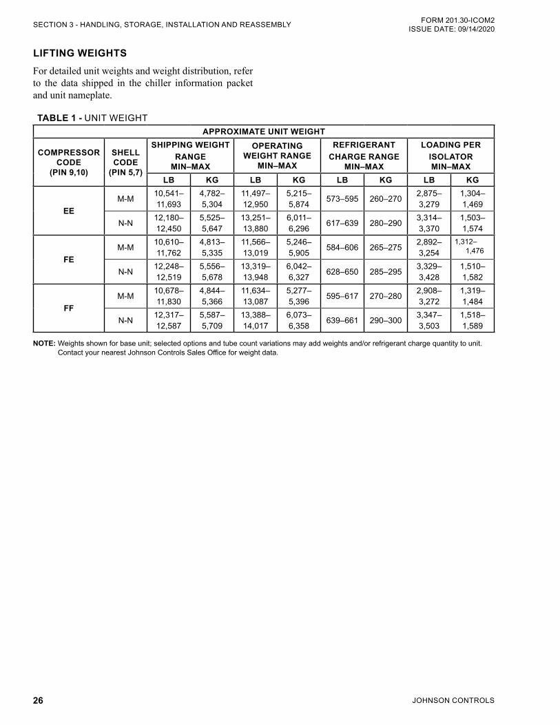
TABLE 1 - UNIT WEIGHTAPPROXIMATE UNIT WEIGHT
COMPRESSOR CODE
(PIN 9,10)
SHELL CODE
(PIN 5,7)
SHIPPING WEIGHT RANGE
MIN–MAX
OPERATING WEIGHT RANGE
MIN–MAX
REFRIGERANT CHARGE RANGE
MIN–MAX
LOADING PER ISOLATOR MIN–MAX
LB KG LB KG LB KG LB KG
EEM-M 10,541–
11,6934,782–5,304
11,497–12,950
5,215–5,874 573–595 260–270 2,875–
3,2791,304–1,469
N-N 12,180–12,450
5,525–5,647
13,251–13,880
6,011–6,296 617–639 280–290 3,314–
3,3701,503–1,574
FEM-M 10,610–
11,7624,813–5,335
11,566–13,019
5,246–5,905 584–606 265–275 2,892–
3,2541,312–
1,476
N-N 12,248–12,519
5,556–5,678
13,319–13,948
6,042–6,327 628–650 285–295 3,329–
3,4281,510–1,582
FFM-M 10,678–
11,8304,844–5,366
11,634–13,087
5,277–5,396 595–617 270–280 2,908–
3,2721,319–1,484
N-N 12,317–12,587
5,587–5,709
13,388–14,017
6,073–6,358 639–661 290–300 3,347–
3,5031,518–1,589
NOTE: Weights shown for base unit; selected options and tube count variations may add weights and/or refrigerant charge quantity to unit. Contact your nearest Johnson Controls Sales Office for weight data.
LIFTING WEIGHTSFor detailed unit weights and weight distribution, refer to the data shipped in the chiller information packet and unit nameplate.
JOHNSON CONTROLS 27
SECTION 3 - HANDLING, STORAGE, INSTALLATION AND REASSEMBLYFORM 201.30-ICOM2 ISSUE DATE: 09/14/2020
3
MOVING THE CHILLER FOR FORMS 1 AND 2Before moving the unit, make sure that the installation site is suitable for installing the unit and is easily ca-pable of supporting the weight of the unit and all as-sociated services.
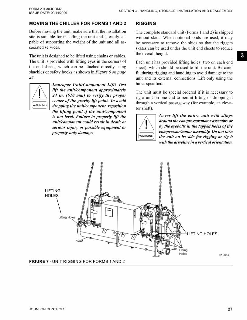
The unit is designed to be lifted using chains or cables. The unit is provided with lifting eyes in the corners of the end sheets, which can be attached directly using shackles or safety hooks as shown in Figure 6 on page 28.
Improper Unit/Component Lift! Test lift the unit/component approximately 24 in. (610 mm) to verify the proper center of the gravity lift point. To avoid dropping the unit/component, reposition the lifting point if the unit/component is not level. Failure to properly lift the unit/component could result in death or serious injury or possible equipment or property-only damage.
RIGGING
The complete standard unit (Forms 1 and 2) is shipped without skids. When optional skids are used, it may be necessary to remove the skids so that the riggers skates can be used under the unit end sheets to reduce the overall height.
Each unit has provided lifting holes (two on each end sheet), which should be used to lift the unit. Be care-ful during rigging and handling to avoid damage to the unit and its external connections. Lift only using the holes specified.
The unit must be special ordered if it is necessary to rig a unit on one end to permit lifting or dropping it through a vertical passageway (for example, an eleva-tor shaft).
Never lift the entire unit with slings around the compressor/motor assembly or by the eyebolts in the tapped holes of the compressor/motor assembly. Do not turn the unit on its side for rigging or rig it with the driveline in a vertical orientation.
LIFTING HOLES
LD16424
FIGURE 7 - UNIT RIGGING FOR FORMS 1 AND 2
LIFTING HOLES
JOHNSON CONTROLS28
FORM 201.30-ICOM2ISSUE DATE: 09/14/2020SECTION 3 - HANDLING, STORAGE, INSTALLATION AND REASSEMBLY
LOCATION Locate the chiller in an indoor location with tempera-ture ranges from 40°F to 110°F (4°C to 43°C) and ad-equate ventilation that meets the all ANSI, state, and local codes.
FOUNDATIONA level floor, foundation, or a customer supplied house-keeping pad must be provided by the customer, which is capable of supporting the unit operating weight.
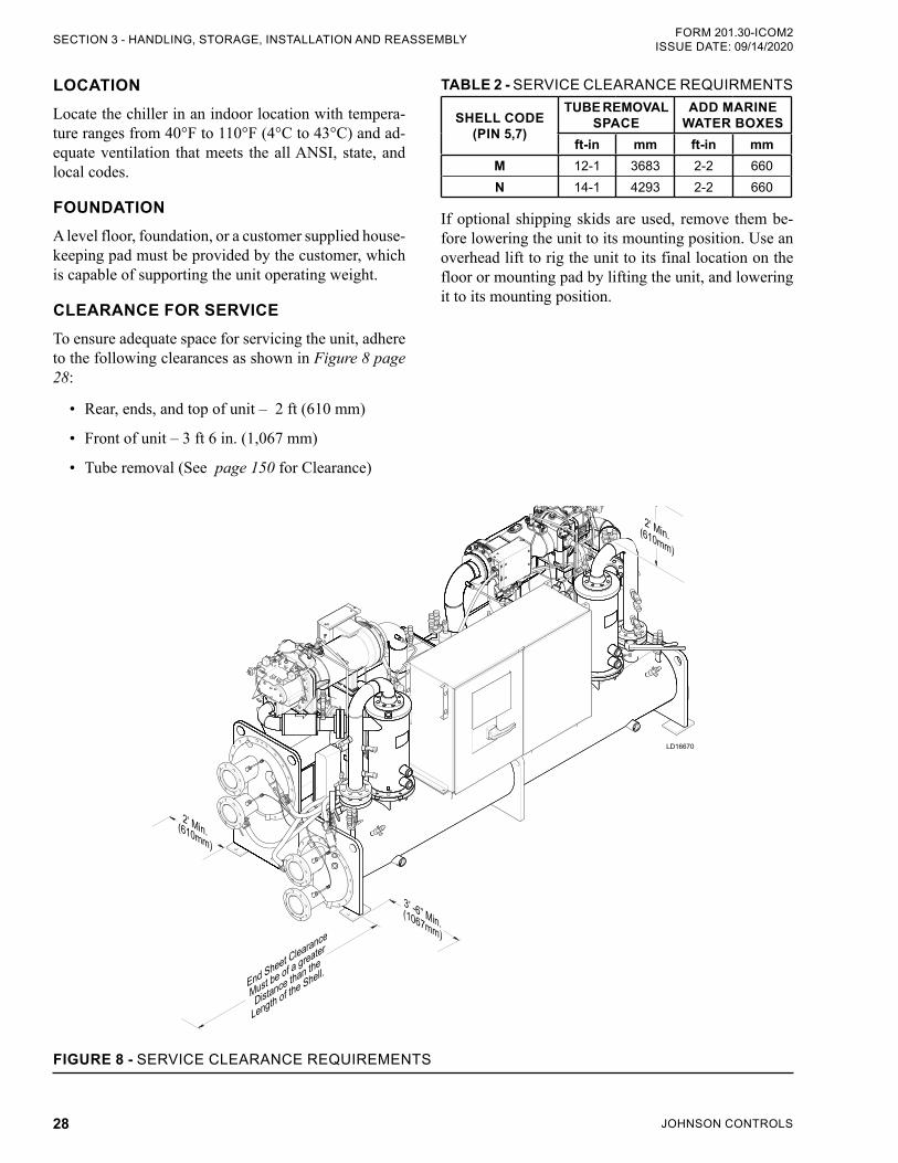
CLEARANCE FOR SERVICE To ensure adequate space for servicing the unit, adhere to the following clearances as shown in Figure 8 page 28:
• Rear, ends, and top of unit – 2 ft (610 mm)
• Front of unit – 3 ft 6 in. (1,067 mm)
• Tube removal (See page 150 for Clearance)
TABLE 2 - SERVICE CLEARANCE REQUIRMENTS
SHELL CODE (PIN 5,7)
TUBE REMOVAL SPACE
ADD MARINE WATER BOXES
ft-in mm ft-in mmM 12-1 3683 2-2 660N 14-1 4293 2-2 660
If optional shipping skids are used, remove them be-fore lowering the unit to its mounting position. Use an overhead lift to rig the unit to its final location on the floor or mounting pad by lifting the unit, and lowering it to its mounting position.
LD16670
3’ -6” Min.(1067mm)
2’ Min.(610mm)
2’ Min.(610mm)
End Sheet Clearance
Must be of a greater
Distance than the
Length of the Shell.
FIGURE 8 - SERVICE CLEARANCE REQUIREMENTS
JOHNSON CONTROLS 29
SECTION 3 - HANDLING, STORAGE, INSTALLATION AND REASSEMBLYFORM 201.30-ICOM2 ISSUE DATE: 09/14/2020
3
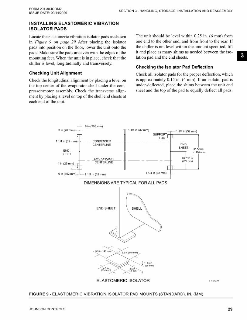
INSTALLING ELASTOMERIC VIBRATION ISOLATOR PADSLocate the elastomeric vibration isolator pads as shown in Figure 9 on page 29 After placing the isolator pads into position on the floor, lower the unit onto the pads. Make sure the pads are even with the edges of the mounting feet. When the unit is in place, check that the chiller is level, longitudinally and transversely.
Checking Unit AlignmentCheck the longitudinal alignment by placing a level on the top center of the evaporator shell under the com-pressor/motor assembly. Check the transverse align-ment by placing a level on top of the shell end sheets at each end of the unit.
The unit should be level within 0.25 in. (6 mm) from one end to the other end, and from front to the rear. If the chiller is not level within the amount specified, lift it and place as many shims as needed between the iso-lation pad and the end sheets.
Checking the Isolator Pad DeflectionCheck all isolator pads for the proper deflection, which is approximately 0.15 in. (4 mm). If an isolator pad is under-deflected, place the shims between the unit end sheet and the top of the pad to equally deflect all pads.
8 in (203 mm)3 in (76 mm)
1 1/4 in (32 mm)
1 in (25 mm)
6 in (152 mm) 1 1/4 in (32 mm)
1 1/4 in (32 mm)
1 1/4 in (32 mm)
1 1/4 in (32 mm)
END SHEET 55 5/16 in
(1404 mm)
28 7/16 in (722 mm)
DIMENSIONS ARE TYPICAL FOR ALL PADS
ELASTOMERIC ISOLATOR
5.5 in (140 mm)
4.5 in (114 mm)
4.5 in (114 mm)
1.5 in (38 mm)
5.5 in (140 mm)
CONDENSER CENTERLINE
EVAPORATOR CENTERLINE
SUPPORTFOOT
END SHEET
END SHEET SHELL
LD16425
FIGURE 9 - ELASTOMERIC VIBRATION ISOLATOR PAD MOUNTS (STANDARD), IN. (MM)
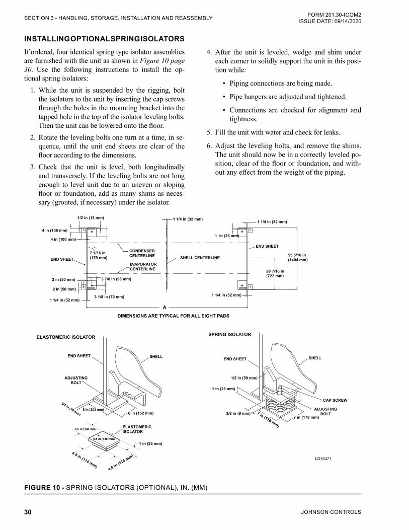
JOHNSON CONTROLS30
FORM 201.30-ICOM2ISSUE DATE: 09/14/2020SECTION 3 - HANDLING, STORAGE, INSTALLATION AND REASSEMBLY
INSTALLING OPTIONAL SPRING ISOLATORSIf ordered, four identical spring type isolator assemblies are furnished with the unit as shown in Figure 10 page 30. Use the following instructions to install the op-tional spring isolators:
1. While the unit is suspended by the rigging, bolt the isolators to the unit by inserting the cap screws through the holes in the mounting bracket into the tapped hole in the top of the isolator leveling bolts. Then the unit can be lowered onto the floor.
2. Rotate the leveling bolts one turn at a time, in se-quence, until the unit end sheets are clear of the floor according to the dimensions.
3. Check that the unit is level, both longitudinally and transversely. If the leveling bolts are not long enough to level unit due to an uneven or sloping floor or foundation, add as many shims as neces-sary (grouted, if necessary) under the isolator.
4. After the unit is leveled, wedge and shim under each corner to solidly support the unit in this posi-tion while:
• Piping connections are being made.
• Pipe hangers are adjusted and tightened.
• Connections are checked for alignment and tightness.
5. Fill the unit with water and check for leaks.
6. Adjust the leveling bolts, and remove the shims. The unit should now be in a correctly leveled po-sition, clear of the floor or foundation, and with-out any effect from the weight of the piping.
END SHEET
CONDENSER CENTERLINE
EVAPORATOR CENTERLINE
SHELL CENTERLINE
DIMENSIONS ARE TYPICAL FOR ALL EIGHT PADS
1 1/4 in (32 mm)
1 1/4 in (32 mm)
1 in (25 mm)
1/2 in (13 mm)
4 in (100 mm)
7 1/16 in (179 mm)
3 7/8 in (98 mm)
3 1/8 in (79 mm)
55 5/16 in (1404 mm)
28 7/16 in (722 mm)
END SHEET SHELL
CAP SCREW
ADJUSTING BOLT3/8 in (9 mm)
1/2 in (50 mm)
7 in (178 mm)
7 in (178 mm)
1 in (25 mm)
ELASTOMERIC ISOLATOR
2 in (50 mm)
2 in (50 mm)
4 in (100 mm)
SPRING ISOLATOR
END SHEET
1 1/4 in (32 mm)
1 1/4 in (32 mm)
SHELLEND SHEET
ELASTOMERIC ISOLATOR
5.5 in (140 mm)
4.8 in (114 mm)4.8 in (114 mm)
1 in (25 mm)
5.5 in (140 mm)
ADJUSTING BOLT
3/4 in (19 mm) 6 in (152 mm)8 in (203 mm)
LD16471
FIGURE 10 - SPRING ISOLATORS (OPTIONAL), IN. (MM)
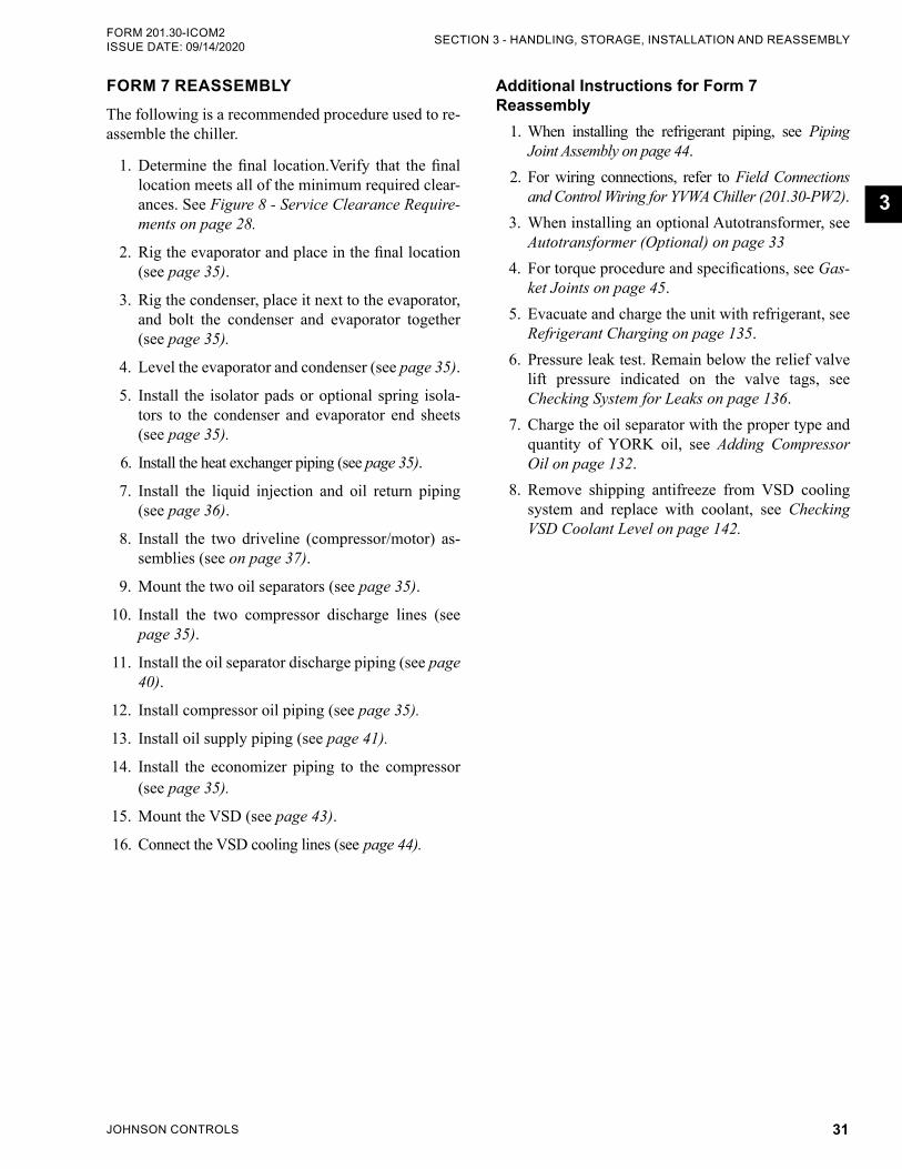
JOHNSON CONTROLS 31
SECTION 3 - HANDLING, STORAGE, INSTALLATION AND REASSEMBLYFORM 201.30-ICOM2 ISSUE DATE: 09/14/2020
3
FORM 7 REASSEMBLYThe following is a recommended procedure used to re-assemble the chiller.
1. Determine the final location.Verify that the final location meets all of the minimum required clear-ances. See Figure 8 - Service Clearance Require-ments on page 28.
2. Rig the evaporator and place in the final location (see page 35).
3. Rig the condenser, place it next to the evaporator, and bolt the condenser and evaporator together (see page 35).
4. Level the evaporator and condenser (see page 35).
5. Install the isolator pads or optional spring isola-tors to the condenser and evaporator end sheets (see page 35).
6. Install the heat exchanger piping (see page 35).
7. Install the liquid injection and oil return piping (see page 36).
8. Install the two driveline (compressor/motor) as-semblies (see on page 37).
9. Mount the two oil separators (see page 35).
10. Install the two compressor discharge lines (see page 35).
11. Install the oil separator discharge piping (see page 40).
12. Install compressor oil piping (see page 35).
13. Install oil supply piping (see page 41).
14. Install the economizer piping to the compressor (see page 35).
15. Mount the VSD (see page 43).
16. Connect the VSD cooling lines (see page 44).
Additional Instructions for Form 7 Reassembly
1. When installing the refrigerant piping, see Piping Joint Assembly on page 44.
2. For wiring connections, refer to Field Connections and Control Wiring for YVWA Chiller (201.30-PW2).
3. When installing an optional Autotransformer, see Autotransformer (Optional) on page 33
4. For torque procedure and specifications, see Gas-ket Joints on page 45.
5. Evacuate and charge the unit with refrigerant, see Refrigerant Charging on page 135.
6. Pressure leak test. Remain below the relief valve lift pressure indicated on the valve tags, see Checking System for Leaks on page 136.
7. Charge the oil separator with the proper type and quantity of YORK oil, see Adding Compressor Oil on page 132.
8. Remove shipping antifreeze from VSD cooling system and replace with coolant, see Checking VSD Coolant Level on page 142.
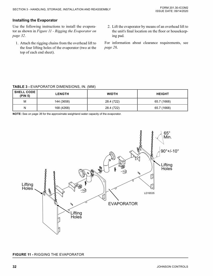
JOHNSON CONTROLS32
FORM 201.30-ICOM2ISSUE DATE: 09/14/2020SECTION 3 - HANDLING, STORAGE, INSTALLATION AND REASSEMBLY
Installing the EvaporatorUse the following instructions to install the evapora-tor as shown in Figure 11 - Rigging the Evaporator on page 32.
1. Attach the rigging chains from the overhead lift to the four lifting holes of the evaporator (two at the top of each end sheet).
TABLE 3 - EVAPORATOR DIMENSIONS, IN. (MM)SHELL CODE
(PIN 5) LENGTH WIDTH HEIGHT
M 144 (3658) 28.4 (722) 65.7 (1668)
N 168 (4268) 28.4 (722) 65.7 (1668)
NOTE: See on page 36 for the approximate weightand water capacity of the evaporator.
LD16535
90°+/-10°
65° Min.
LiftingHoles
LiftingHoles
LiftingHoles
EVAPORATOR
FIGURE 11 - RIGGING THE EVAPORATOR
2. Lift the evaporator by means of an overhead lift to the unit's final location on the floor or housekeep-ing pad.
For information about clearance requirements, see page 28.
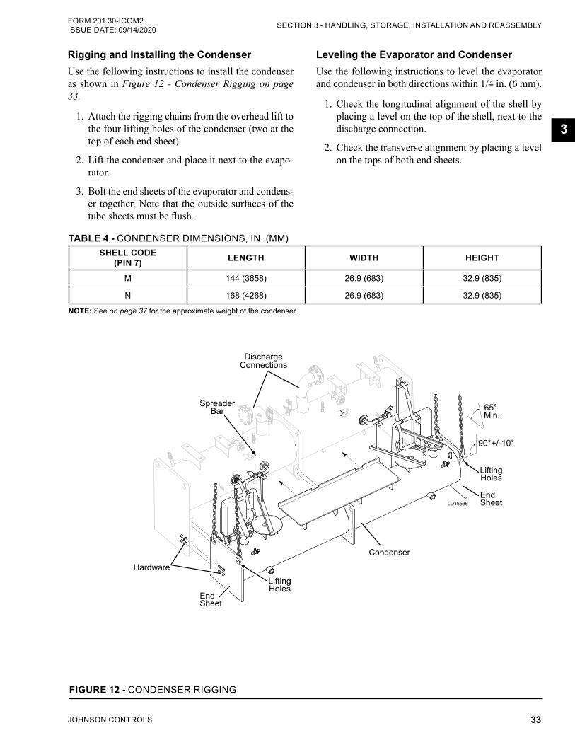
JOHNSON CONTROLS 33
SECTION 3 - HANDLING, STORAGE, INSTALLATION AND REASSEMBLYFORM 201.30-ICOM2 ISSUE DATE: 09/14/2020
3
Rigging and Installing the CondenserUse the following instructions to install the condenser as shown in Figure 12 - Condenser Rigging on page 33.
1. Attach the rigging chains from the overhead lift to the four lifting holes of the condenser (two at the top of each end sheet).
2. Lift the condenser and place it next to the evapo-rator.
3. Bolt the end sheets of the evaporator and condens-er together. Note that the outside surfaces of the tube sheets must be flush.
Leveling the Evaporator and Condenser Use the following instructions to level the evaporator and condenser in both directions within 1/4 in. (6 mm).
1. Check the longitudinal alignment of the shell by placing a level on the top of the shell, next to the discharge connection.
2. Check the transverse alignment by placing a level on the tops of both end sheets.
TABLE 4 - CONDENSER DIMENSIONS, IN. (MM)SHELL CODE
(PIN 7) LENGTH WIDTH HEIGHT
M 144 (3658) 26.9 (683) 32.9 (835)
N 168 (4268) 26.9 (683) 32.9 (835)
NOTE: See on page 37 for the approximate weight of the condenser.
LD16536
90°+/-10°
65° Min.
LiftingHoles
LiftingHoles
EndSheet
SpreaderBar
DischargeConnections
Condenser
EndSheet
Hardware
FIGURE 12 - CONDENSER RIGGING
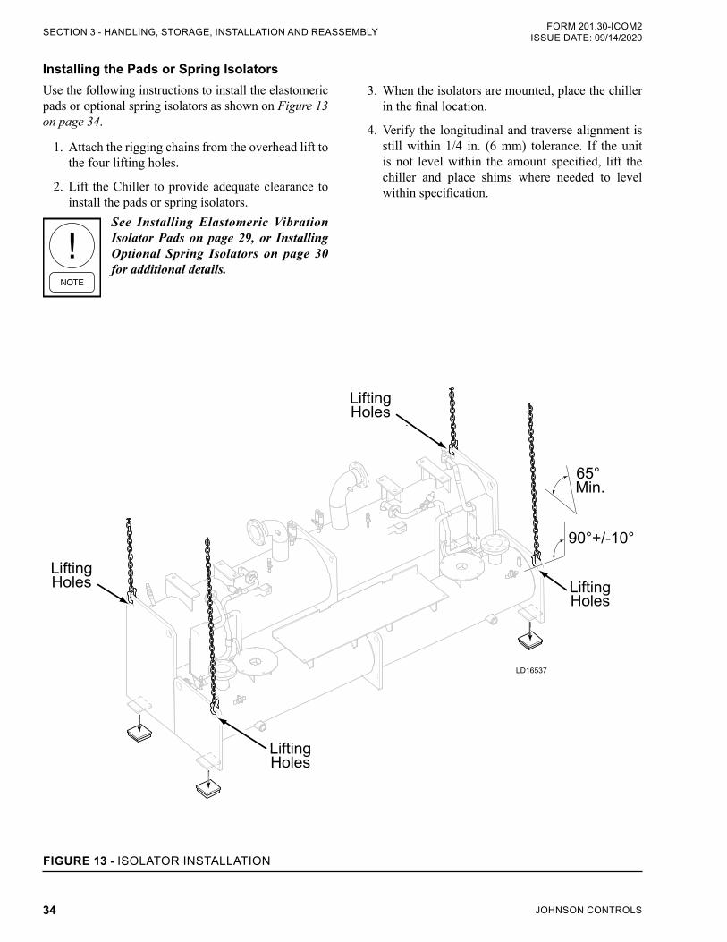
JOHNSON CONTROLS34
FORM 201.30-ICOM2ISSUE DATE: 09/14/2020SECTION 3 - HANDLING, STORAGE, INSTALLATION AND REASSEMBLY
Installing the Pads or Spring IsolatorsUse the following instructions to install the elastomeric pads or optional spring isolators as shown on Figure 13 on page 34.
1. Attach the rigging chains from the overhead lift to the four lifting holes.
2. Lift the Chiller to provide adequate clearance to install the pads or spring isolators.
See Installing Elastomeric Vibration Isolator Pads on page 29, or Installing Optional Spring Isolators on page 30 for additional details.
3. When the isolators are mounted, place the chiller in the final location.
4. Verify the longitudinal and traverse alignment is still within 1/4 in. (6 mm) tolerance. If the unit is not level within the amount specified, lift the chiller and place shims where needed to level within specification.
LD16537
90°+/-10°
65° Min.
LiftingHoles
LiftingHoles
LiftingHoles
LiftingHoles
FIGURE 13 - ISOLATOR INSTALLATION
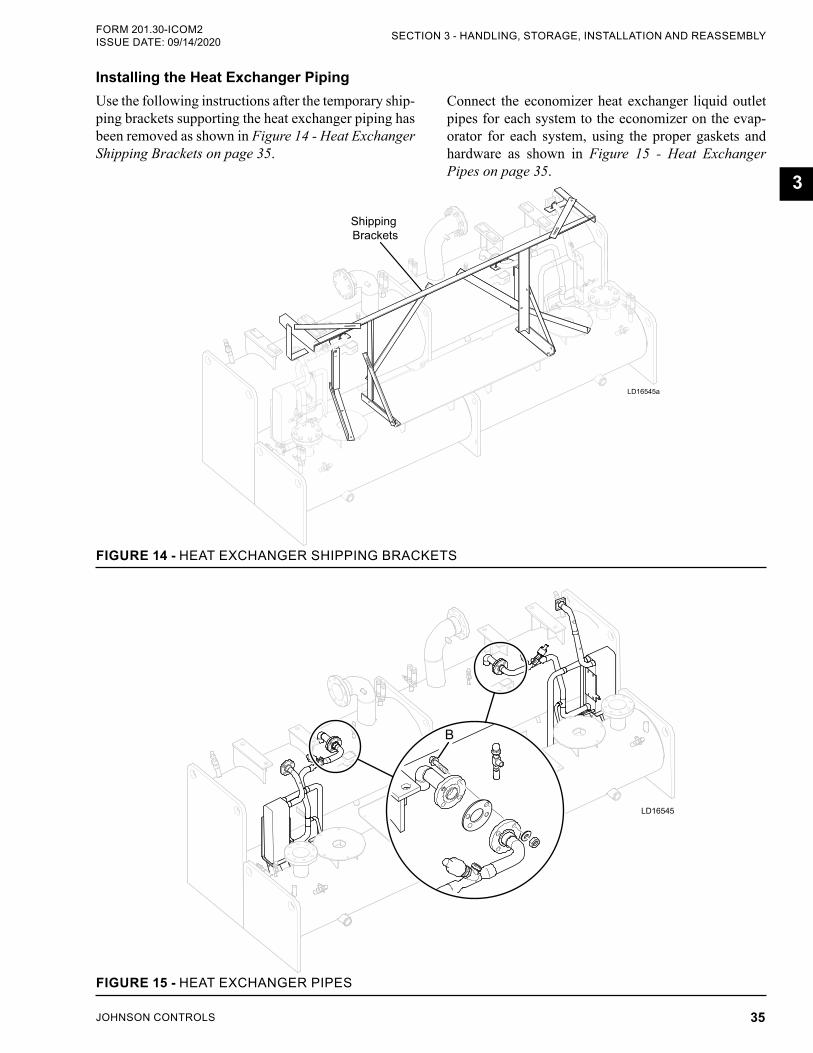
JOHNSON CONTROLS 35
SECTION 3 - HANDLING, STORAGE, INSTALLATION AND REASSEMBLYFORM 201.30-ICOM2 ISSUE DATE: 09/14/2020
3
Connect the economizer heat exchanger liquid outlet pipes for each system to the economizer on the evap-orator for each system, using the proper gaskets and hardware as shown in Figure 15 - Heat Exchanger Pipes on page 35.
Installing the Heat Exchanger Piping Use the following instructions after the temporary ship-ping brackets supporting the heat exchanger piping has been removed as shown in Figure 14 - Heat Exchanger Shipping Brackets on page 35.
LD16545a
Shipping Brackets
FIGURE 14 - HEAT EXCHANGER SHIPPING BRACKETS
LD16545
B
FIGURE 15 - HEAT EXCHANGER PIPES
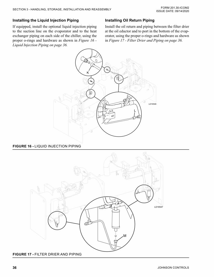
JOHNSON CONTROLS36
FORM 201.30-ICOM2ISSUE DATE: 09/14/2020SECTION 3 - HANDLING, STORAGE, INSTALLATION AND REASSEMBLY
LD16546
K
L
FIGURE 16 - LIQUID INJECTION PIPING
LD16547
M
FIGURE 17 - FILTER DRIER AND PIPING
Installing the Liquid Injection PipingIf equipped, install the optional liquid injection piping to the suction line on the evaporator and to the heat exchanger piping on each side of the chiller, using the proper o-rings and hardware as shown in Figure 16 - Liquid Injection Piping on page 36.
Installing Oil Return PipingInstall the oil return and piping between the filter drier at the oil eductor and to port in the bottom of the evap-orator, using the proper o-rings and hardware as shown in Figure 17 - Filter Drier and Piping on page 36.
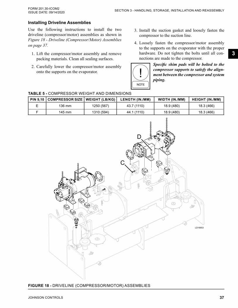
JOHNSON CONTROLS 37
SECTION 3 - HANDLING, STORAGE, INSTALLATION AND REASSEMBLYFORM 201.30-ICOM2 ISSUE DATE: 09/14/2020
3
Installing Driveline AssembliesUse the following instructions to install the two driveline (compressor/motor) assemblies as shown in Figure 18 - Driveline (Compressor/Motor) Assemblies on page 37.
1. Lift the compressor/motor assembly and remove packing materials. Clean all sealing surfaces.
2. Carefully lower the compressor/motor assembly onto the supports on the evaporator.
TABLE 5 - COMPRESSOR WEIGHT AND DIMENSIONSPIN 9,10 COMPRESSOR SIZE WEIGHT (LB/KG) LENGTH (IN./MM) WIDTH (IN./MM) HEIGHT (IN./MM)
E 136 mm 1250 (567) 43.7 (1110) 18.9 (480) 18.3 (466)
F 145 mm 1310 (594) 44.1 (1110) 18.9 (480) 18.3 (466)
LD16653
C
D
FIGURE 18 - DRIVELINE (COMPRESSOR/MOTOR) ASSEMBLIES
3. Install the suction gasket and loosely fasten the compressor to the suction line.
4. Loosely fasten the compressor/motor assembly to the supports on the evaporator with the proper hardware. Do not tighten the bolts until all con-nections are made to the compressor.
Specific shim pads will be bolted to the compressor supports to satisfy the align-ment between the compressor and system piping.
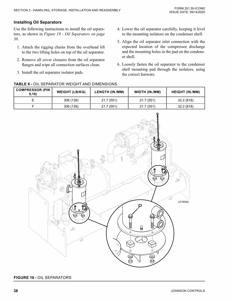
JOHNSON CONTROLS38
FORM 201.30-ICOM2ISSUE DATE: 09/14/2020SECTION 3 - HANDLING, STORAGE, INSTALLATION AND REASSEMBLY
TABLE 6 - OIL SEPARATOR WEIGHT AND DIMENSIONSCOMPRESSOR (PIN
9,10) WEIGHT (LB/KG) LENGTH (IN./MM) WIDTH (IN./MM) HEIGHT (IN./MM)
E 306 (139) 21.7 (551) 21.7 (551) 32.2 (818)
F 306 (139) 21.7 (551) 21.7 (551) 32.2 (818)
LD16549
P
FIGURE 19 - OIL SEPARATORS
Installing Oil SeparatorsUse the following instructions to install the oil separa-tors, as shown in Figure 19 - Oil Separators on page 38.
1. Attach the rigging chains from the overhead lift to the two lifting holes on top of the oil separator.
2. Remove all cover closures from the oil separator flanges and wipe all connection surfaces clean.
3. Install the oil separator isolator pads.
4. Lower the oil separator carefully, keeping it level to the mounting isolators on the condenser shell.
5. Align the oil separator inlet connection with the expected location of the compressor discharge and the mounting holes in the pad on the condens-er shell.
6. Loosely fasten the oil separator to the condenser shell mounting pad through the isolators, using the correct harware.
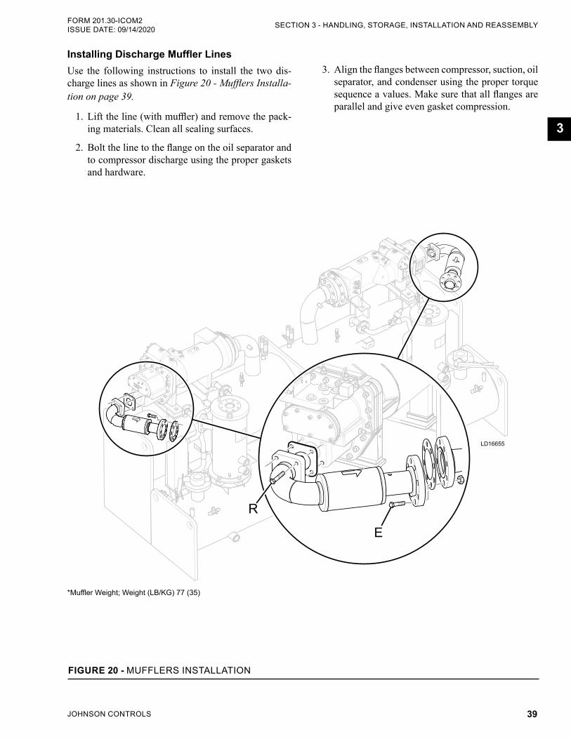
JOHNSON CONTROLS 39
SECTION 3 - HANDLING, STORAGE, INSTALLATION AND REASSEMBLYFORM 201.30-ICOM2 ISSUE DATE: 09/14/2020
3
Installing Discharge Muffler LinesUse the following instructions to install the two dis-charge lines as shown in Figure 20 - Mufflers Installa-tion on page 39.
1. Lift the line (with muffler) and remove the pack-ing materials. Clean all sealing surfaces.
2. Bolt the line to the flange on the oil separator and to compressor discharge using the proper gaskets and hardware.
3. Align the flanges between compressor, suction, oil separator, and condenser using the proper torque sequence a values. Make sure that all flanges are parallel and give even gasket compression.
*Muffler Weight; Weight (LB/KG) 77 (35)
LD16655
E
R
FIGURE 20 - MUFFLERS INSTALLATION
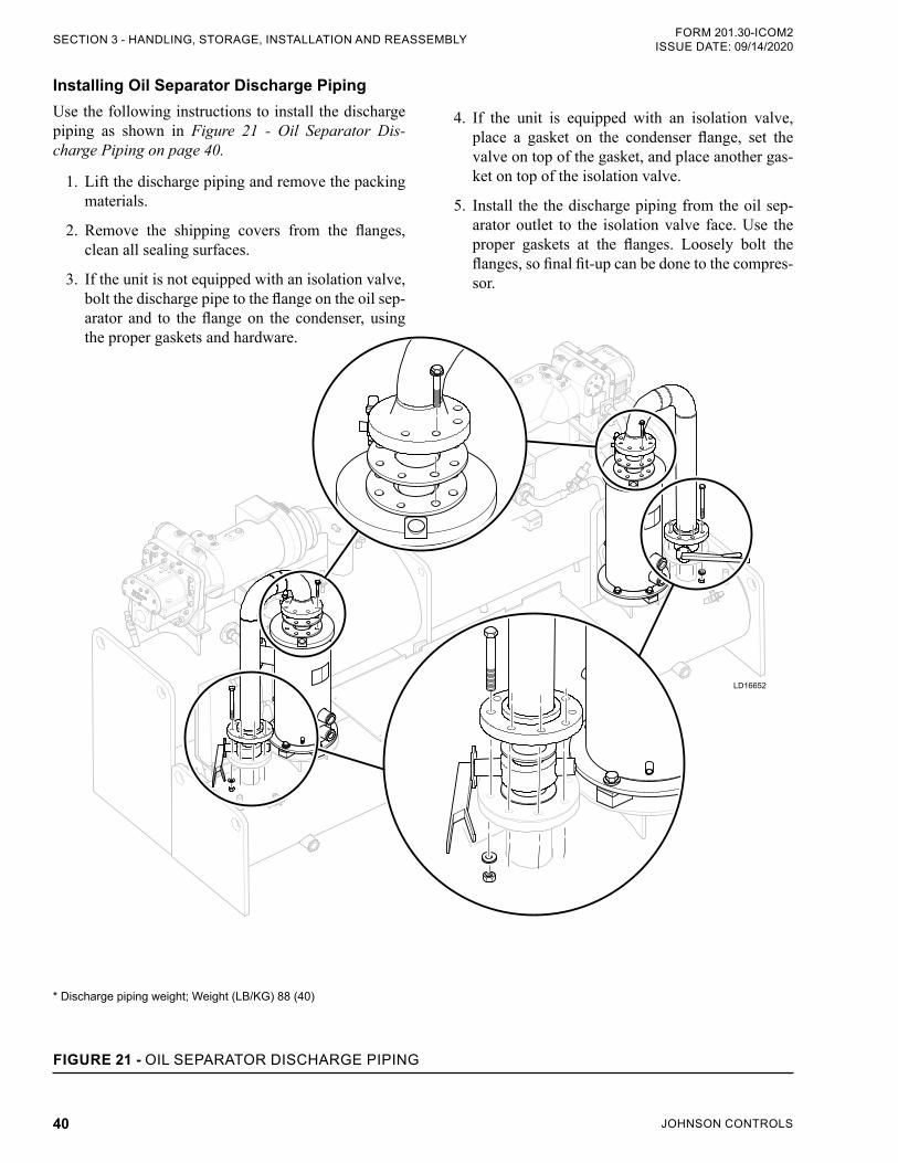
JOHNSON CONTROLS40
FORM 201.30-ICOM2ISSUE DATE: 09/14/2020SECTION 3 - HANDLING, STORAGE, INSTALLATION AND REASSEMBLY
Installing Oil Separator Discharge PipingUse the following instructions to install the discharge piping as shown in Figure 21 - Oil Separator Dis-charge Piping on page 40.
1. Lift the discharge piping and remove the packing materials.
2. Remove the shipping covers from the flanges, clean all sealing surfaces.
3. If the unit is not equipped with an isolation valve, bolt the discharge pipe to the flange on the oil sep-arator and to the flange on the condenser, using the proper gaskets and hardware.
* Discharge piping weight; Weight (LB/KG) 88 (40)
LD16652
FIGURE 21 - OIL SEPARATOR DISCHARGE PIPING
4. If the unit is equipped with an isolation valve, place a gasket on the condenser flange, set the valve on top of the gasket, and place another gas-ket on top of the isolation valve.
5. Install the the discharge piping from the oil sep-arator outlet to the isolation valve face. Use the proper gaskets at the flanges. Loosely bolt the flanges, so final fit-up can be done to the compres-sor.
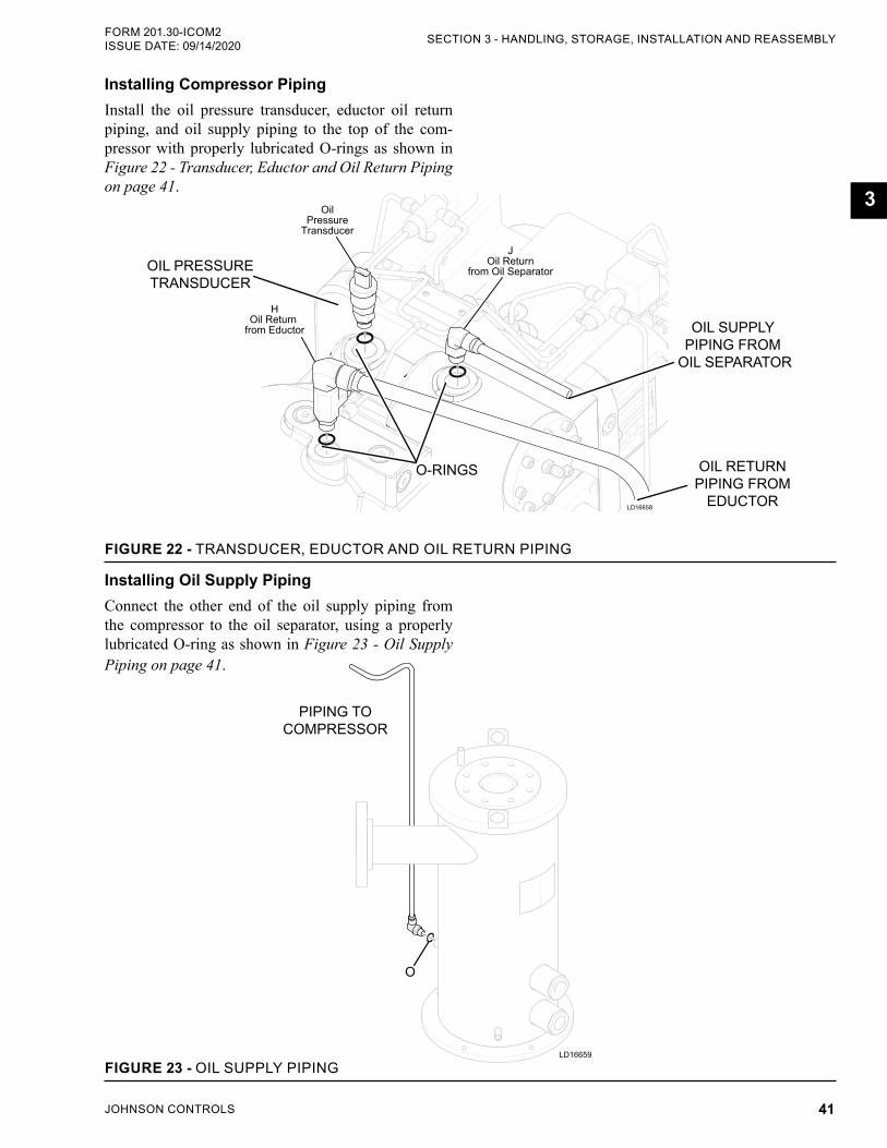
JOHNSON CONTROLS 41
SECTION 3 - HANDLING, STORAGE, INSTALLATION AND REASSEMBLYFORM 201.30-ICOM2 ISSUE DATE: 09/14/2020
3
Installing Compressor PipingInstall the oil pressure transducer, eductor oil return piping, and oil supply piping to the top of the com-pressor with properly lubricated O-rings as shown in Figure 22 - Transducer, Eductor and Oil Return Piping on page 41.
LD16658
JOil Return
from Oil Separator
HOil Return
from Eductor
OilPressure
Transducer
OIL PRESSURE TRANSDUCER
FIGURE 22 - TRANSDUCER, EDUCTOR AND OIL RETURN PIPING
O-RINGS OIL RETURN PIPING FROM
EDUCTOR
OIL SUPPLYPIPING FROM
OIL SEPARATOR
PIPING TO COMPRESSOR
Installing Oil Supply PipingConnect the other end of the oil supply piping from the compressor to the oil separator, using a properly lubricated O-ring as shown in Figure 23 - Oil Supply Piping on page 41.
LD16659
O
FIGURE 23 - OIL SUPPLY PIPING
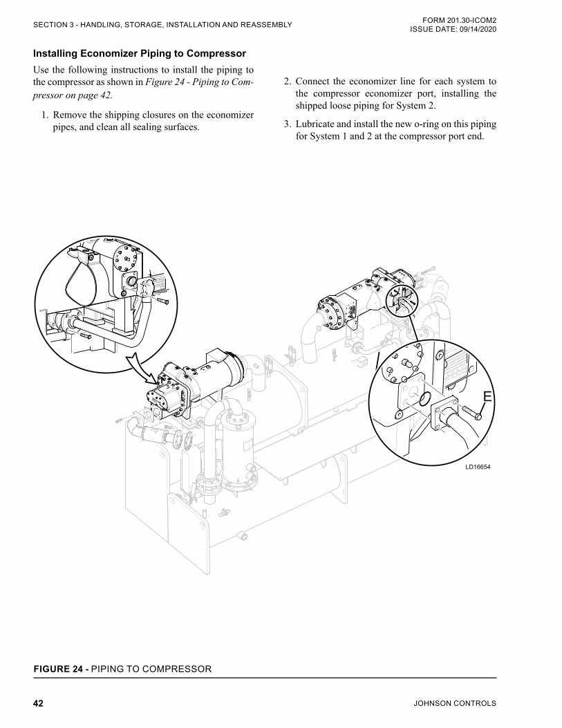
JOHNSON CONTROLS42
FORM 201.30-ICOM2ISSUE DATE: 09/14/2020SECTION 3 - HANDLING, STORAGE, INSTALLATION AND REASSEMBLY
Installing Economizer Piping to CompressorUse the following instructions to install the piping to the compressor as shown in Figure 24 - Piping to Com-pressor on page 42.
1. Remove the shipping closures on the economizer pipes, and clean all sealing surfaces.
2. Connect the economizer line for each system to the compressor economizer port, installing the shipped loose piping for System 2.
3. Lubricate and install the new o-ring on this piping for System 1 and 2 at the compressor port end.
LD16654
E
FIGURE 24 - PIPING TO COMPRESSOR
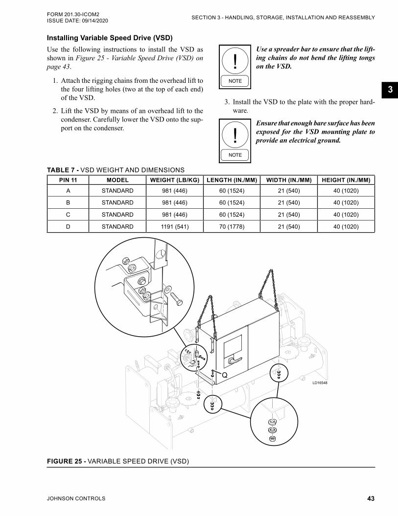
JOHNSON CONTROLS 43
SECTION 3 - HANDLING, STORAGE, INSTALLATION AND REASSEMBLYFORM 201.30-ICOM2 ISSUE DATE: 09/14/2020
3
Installing Variable Speed Drive (VSD)Use the following instructions to install the VSD as shown in Figure 25 - Variable Speed Drive (VSD) on page 43.
1. Attach the rigging chains from the overhead lift to the four lifting holes (two at the top of each end) of the VSD.
2. Lift the VSD by means of an overhead lift to the condenser. Carefully lower the VSD onto the sup-port on the condenser.
TABLE 7 - VSD WEIGHT AND DIMENSIONSPIN 11 MODEL WEIGHT (LB/KG) LENGTH (IN./MM) WIDTH (IN./MM) HEIGHT (IN./MM)
A STANDARD 981 (446) 60 (1524) 21 (540) 40 (1020)
B STANDARD 981 (446) 60 (1524) 21 (540) 40 (1020)
C STANDARD 981 (446) 60 (1524) 21 (540) 40 (1020)
D STANDARD 1191 (541) 70 (1778) 21 (540) 40 (1020)
LD16548
Q
FIGURE 25 - VARIABLE SPEED DRIVE (VSD)
Use a spreader bar to ensure that the lift-ing chains do not bend the lifting tongs on the VSD.
3. Install the VSD to the plate with the proper hard-ware.
Ensure that enough bare surface has been exposed for the VSD mounting plate to provide an electrical ground.
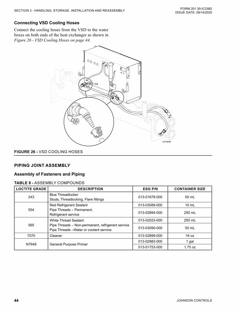
JOHNSON CONTROLS44
FORM 201.30-ICOM2ISSUE DATE: 09/14/2020SECTION 3 - HANDLING, STORAGE, INSTALLATION AND REASSEMBLY
Connecting VSD Cooling HosesConnect the cooling hoses from the VSD to the water boxes on both ends of the heat exchanger as shown in Figure 26 - VSD Cooling Hoses on page 44.
LD16656
FIGURE 26 - VSD COOLING HOSES
PIPING JOINT ASSEMBLY
Assembly of Fasteners and Piping
TABLE 8 - ASSEMBLY COMPOUNDSLOCTITE GRADE DESCRIPTION ESG P/N CONTAINER SIZE
243 Blue Threadlocker Studs, Threadlocking, Flare fittings 013-01678-000 50 mL
554Red Refrigerant Sealant Pipe Threads – Permanent, Refrigerant service
013-03089-000 10 mL
013-02894-000 250 mL
565White Thread Sealant Pipe Threads – Non-permanent, refrigerant service Pipe Threads –Water or coolant service
013-02023-000 250 mL
013-03090-000 50 mL
7070 Cleaner 013-02899-000 16 oz
N7649 General Purpose Primer013-02982-000 1 gal013-01753-000 1.75 oz
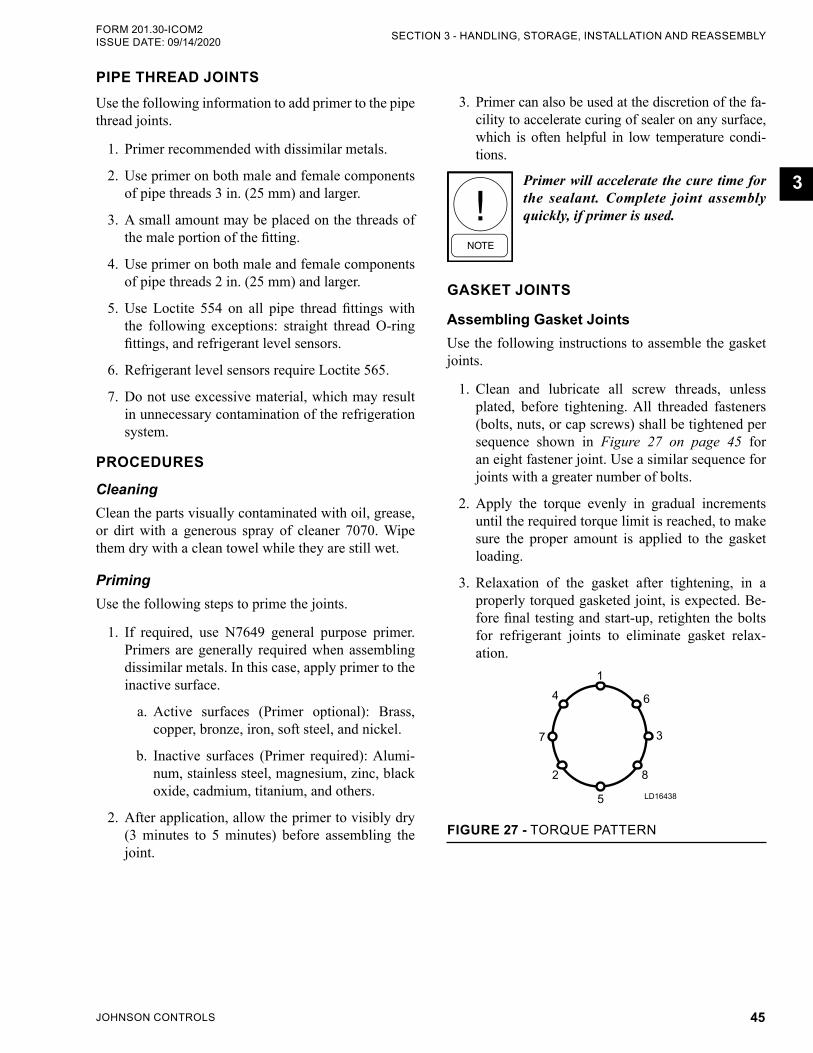
JOHNSON CONTROLS 45
SECTION 3 - HANDLING, STORAGE, INSTALLATION AND REASSEMBLYFORM 201.30-ICOM2 ISSUE DATE: 09/14/2020
3
PIPE THREAD JOINTSUse the following information to add primer to the pipe thread joints.
1. Primer recommended with dissimilar metals.
2. Use primer on both male and female components of pipe threads 3 in. (25 mm) and larger.
3. A small amount may be placed on the threads of the male portion of the fitting.
4. Use primer on both male and female components of pipe threads 2 in. (25 mm) and larger.
5. Use Loctite 554 on all pipe thread fittings with the following exceptions: straight thread O-ring fittings, and refrigerant level sensors.
6. Refrigerant level sensors require Loctite 565.
7. Do not use excessive material, which may result in unnecessary contamination of the refrigeration system.
PROCEDURES
CleaningClean the parts visually contaminated with oil, grease, or dirt with a generous spray of cleaner 7070. Wipe them dry with a clean towel while they are still wet.
PrimingUse the following steps to prime the joints.
1. If required, use N7649 general purpose primer. Primers are generally required when assembling dissimilar metals. In this case, apply primer to the inactive surface.
a. Active surfaces (Primer optional): Brass, copper, bronze, iron, soft steel, and nickel.
b. Inactive surfaces (Primer required): Alumi-num, stainless steel, magnesium, zinc, black oxide, cadmium, titanium, and others.
2. After application, allow the primer to visibly dry (3 minutes to 5 minutes) before assembling the joint.
3. Primer can also be used at the discretion of the fa-cility to accelerate curing of sealer on any surface, which is often helpful in low temperature condi-tions.
Primer will accelerate the cure time for the sealant. Complete joint assembly quickly, if primer is used.
GASKET JOINTS
Assembling Gasket JointsUse the following instructions to assemble the gasket joints.
1. Clean and lubricate all screw threads, unless plated, before tightening. All threaded fasteners (bolts, nuts, or cap screws) shall be tightened per sequence shown in Figure 27 on page 45 for an eight fastener joint. Use a similar sequence for joints with a greater number of bolts.
2. Apply the torque evenly in gradual increments until the required torque limit is reached, to make sure the proper amount is applied to the gasket loading.
3. Relaxation of the gasket after tightening, in a properly torqued gasketed joint, is expected. Be-fore final testing and start-up, retighten the bolts for refrigerant joints to eliminate gasket relax-ation.
1
2
7
4 6
5
8
3
FIGURE 27 - TORQUE PATTERN
LD16438
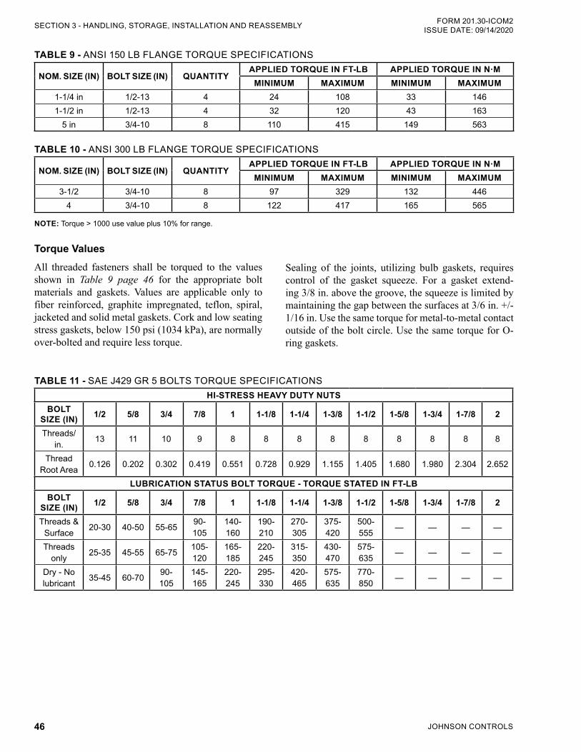
JOHNSON CONTROLS46
FORM 201.30-ICOM2ISSUE DATE: 09/14/2020SECTION 3 - HANDLING, STORAGE, INSTALLATION AND REASSEMBLY
TABLE 9 - ANSI 150 LB FLANGE TORQUE SPECIFICATIONS
NOM. SIZE (IN) BOLT SIZE (IN) QUANTITYAPPLIED TORQUE IN FT-LB APPLIED TORQUE IN N·M
MINIMUM MAXIMUM MINIMUM MAXIMUM1-1/4 in 1/2-13 4 24 108 33 1461-1/2 in 1/2-13 4 32 120 43 163
5 in 3/4-10 8 110 415 149 563
TABLE 10 - ANSI 300 LB FLANGE TORQUE SPECIFICATIONS
NOM. SIZE (IN) BOLT SIZE (IN) QUANTITYAPPLIED TORQUE IN FT-LB APPLIED TORQUE IN N·M
MINIMUM MAXIMUM MINIMUM MAXIMUM3-1/2 3/4-10 8 97 329 132 446
4 3/4-10 8 122 417 165 565
NOTE: Torque > 1000 use value plus 10% for range.
Torque ValuesAll threaded fasteners shall be torqued to the values shown in Table 9 page 46 for the appropriate bolt materials and gaskets. Values are applicable only to fiber reinforced, graphite impregnated, teflon, spiral, jacketed and solid metal gaskets. Cork and low seating stress gaskets, below 150 psi (1034 kPa), are normally over-bolted and require less torque.
TABLE 11 - SAE J429 GR 5 BOLTS TORQUE SPECIFICATIONSHI-STRESS HEAVY DUTY NUTS
BOLT SIZE (IN) 1/2 5/8 3/4 7/8 1 1-1/8 1-1/4 1-3/8 1-1/2 1-5/8 1-3/4 1-7/8 2
Threads/in. 13 11 10 9 8 8 8 8 8 8 8 8 8
Thread Root Area 0.126 0.202 0.302 0.419 0.551 0.728 0.929 1.155 1.405 1.680 1.980 2.304 2.652
LUBRICATION STATUS BOLT TORQUE - TORQUE STATED IN FT-LBBOLT
SIZE (IN) 1/2 5/8 3/4 7/8 1 1-1/8 1-1/4 1-3/8 1-1/2 1-5/8 1-3/4 1-7/8 2
Threads & Surface 20-30 40-50 55-65 90-
105140-160
190-210
270-305
375-420
500-555 — — — —
Threads only 25-35 45-55 65-75 105-
120165-185
220-245
315-350
430-470
575-635 — — — —
Dry - No lubricant 35-45 60-70 90-
105145-165
220-245
295-330
420-465
575-635
770-850 — — — —
Sealing of the joints, utilizing bulb gaskets, requires control of the gasket squeeze. For a gasket extend-ing 3/8 in. above the groove, the squeeze is limited by maintaining the gap between the surfaces at 3/6 in. +/- 1/16 in. Use the same torque for metal-to-metal contact outside of the bolt circle. Use the same torque for O-ring gaskets.
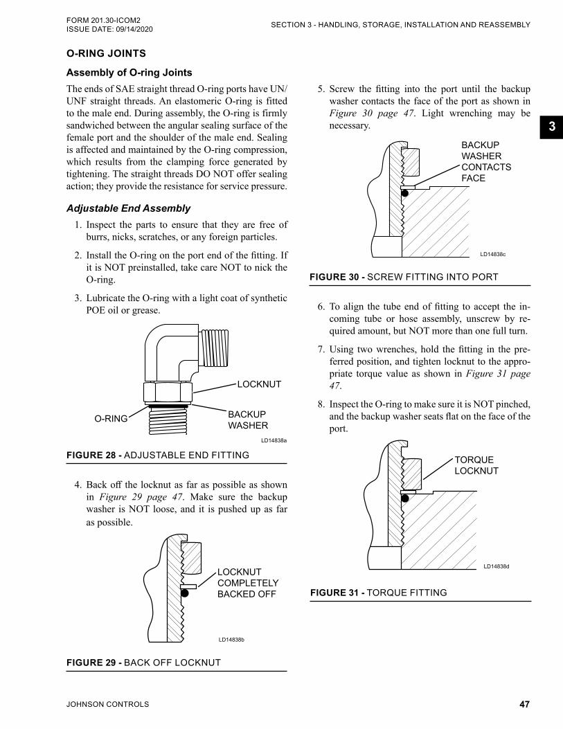
JOHNSON CONTROLS 47
SECTION 3 - HANDLING, STORAGE, INSTALLATION AND REASSEMBLYFORM 201.30-ICOM2 ISSUE DATE: 09/14/2020
3
5. Screw the fitting into the port until the backup washer contacts the face of the port as shown in Figure 30 page 47. Light wrenching may be necessary.
LD14838c
FIGURE 30 - SCREW FITTING INTO PORT
BACKUP WASHER CONTACTS FACE
6. To align the tube end of fitting to accept the in-coming tube or hose assembly, unscrew by re-quired amount, but NOT more than one full turn.
7. Using two wrenches, hold the fitting in the pre-ferred position, and tighten locknut to the appro-priate torque value as shown in Figure 31 page 47.
8. Inspect the O-ring to make sure it is NOT pinched, and the backup washer seats flat on the face of the port.
LD14838d
FIGURE 31 - TORQUE FITTING
TORQUE LOCKNUT
O-RING JOINTS
Assembly of O-ring JointsThe ends of SAE straight thread O-ring ports have UN/UNF straight threads. An elastomeric O-ring is fitted to the male end. During assembly, the O-ring is firmly sandwiched between the angular sealing surface of the female port and the shoulder of the male end. Sealing is affected and maintained by the O-ring compression, which results from the clamping force generated by tightening. The straight threads DO NOT offer sealing action; they provide the resistance for service pressure.
Adjustable End Assembly1. Inspect the parts to ensure that they are free of
burrs, nicks, scratches, or any foreign particles.
2. Install the O-ring on the port end of the fitting. If it is NOT preinstalled, take care NOT to nick the O-ring.
3. Lubricate the O-ring with a light coat of synthetic POE oil or grease.
O-RING BACKUP WASHER
LOCKNUT
LD14838a
FIGURE 28 - ADJUSTABLE END FITTING
4. Back off the locknut as far as possible as shown in Figure 29 page 47. Make sure the backup washer is NOT loose, and it is pushed up as far as possible.
LD14838b
FIGURE 29 - BACK OFF LOCKNUT
LOCKNUT COMPLETELY BACKED OFF
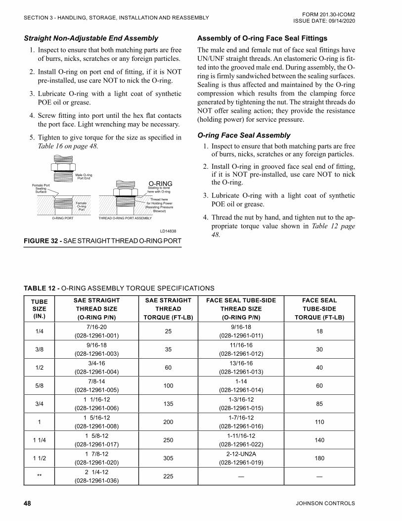
JOHNSON CONTROLS48
FORM 201.30-ICOM2ISSUE DATE: 09/14/2020SECTION 3 - HANDLING, STORAGE, INSTALLATION AND REASSEMBLY
Straight Non-Adjustable End Assembly1. Inspect to ensure that both matching parts are free
of burrs, nicks, scratches or any foreign particles.
2. Install O-ring on port end of fitting, if it is NOT pre-installed, use care NOT to nick the O-ring.
3. Lubricate O-ring with a light coat of synthetic POE oil or grease.
4. Screw fitting into port until the hex flat contacts the port face. Light wrenching may be necessary.
5. Tighten to give torque for the size as specified in Table 16 on page 48.
O-RINGFemale PortSealingSurface
Thread here for Holding Power
(Resisting Pressure Blowout)
Sealing is donehere with O-ring
Male O-ringPort End
O-RING PORT THREAD O-RING PORT ASSEMBLY
Female O-ringPort
LD14838
FIGURE 32 - SAE STRAIGHT THREAD O-RING PORT
Assembly of O-ring Face Seal Fittings The male end and female nut of face seal fittings have UN/UNF straight threads. An elastomeric O-ring is fit-ted into the grooved male end. During assembly, the O-ring is firmly sandwiched between the sealing surfaces. Sealing is thus affected and maintained by the O-ring compression which results from the clamping force generated by tightening the nut. The straight threads do NOT offer sealing action; they provide the resistance (holding power) for service pressure.
O-ring Face Seal Assembly1. Inspect to ensure that both matching parts are free
of burrs, nicks, scratches or any foreign particles.
2. Install O-ring in grooved face seal end of fitting, if it is NOT pre-installed, use care NOT to nick the O-ring.
3. Lubricate O-ring with a light coat of synthetic POE oil or grease.
4. Thread the nut by hand, and tighten nut to the ap-propriate torque value shown in Table 12 page 48.
TABLE 12 - O-RING ASSEMBLY TORQUE SPECIFICATIONS
TUBE SIZE (IN.)
SAE STRAIGHTTHREAD SIZE(O-RING P/N)
SAE STRAIGHT THREAD
TORQUE (FT-LB)
FACE SEAL TUBE-SIDETHREAD SIZE(O-RING P/N)
FACE SEALTUBE-SIDE
TORQUE (FT-LB)
1/47/16-20
(028-12961-001)25
9/16-18(028-12961-011)
18
3/89/16-18
(028-12961-003)35
11/16-16(028-12961-012)
30
1/23/4-16
(028-12961-004)60
13/16-16(028-12961-013)
40
5/87/8-14
(028-12961-005)100
1-14(028-12961-014)
60
3/41 1/16-12
(028-12961-006)135
1-3/16-12(028-12961-015)
85
11 5/16-12
(028-12961-008)200
1-7/16-12(028-12961-016)
110
1 1/41 5/8-12
(028-12961-017)250
1-11/16-12(028-12961-022)
140
1 1/21 7/8-12
(028-12961-020)305
2-12-UN2A(028-12961-019)
180
**2 1/4-12
(028-12961-036)225 — —
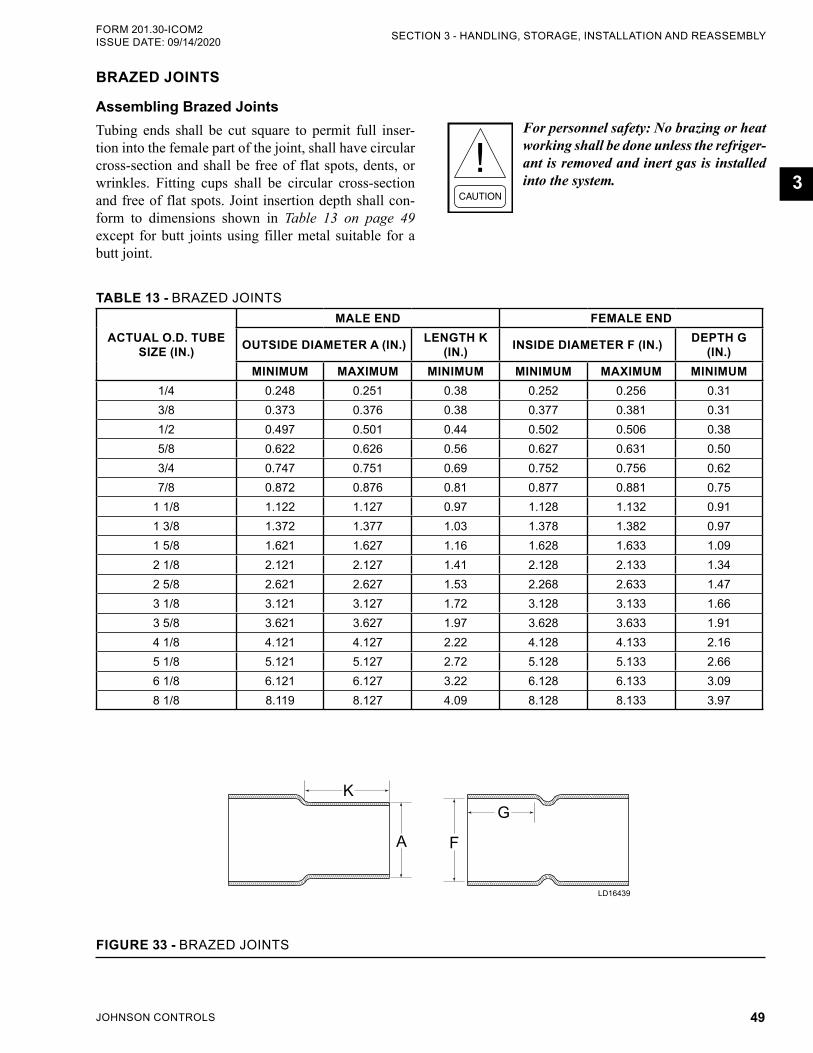
JOHNSON CONTROLS 49
SECTION 3 - HANDLING, STORAGE, INSTALLATION AND REASSEMBLYFORM 201.30-ICOM2 ISSUE DATE: 09/14/2020
3
BRAZED JOINTS
Assembling Brazed JointsTubing ends shall be cut square to permit full inser-tion into the female part of the joint, shall have circular cross-section and shall be free of flat spots, dents, or wrinkles. Fitting cups shall be circular cross-section and free of flat spots. Joint insertion depth shall con-form to dimensions shown in Table 13 on page 49 except for butt joints using filler metal suitable for a butt joint.
For personnel safety: No brazing or heat working shall be done unless the refriger-ant is removed and inert gas is installed into the system.
TABLE 13 - BRAZED JOINTS
ACTUAL O.D. TUBE SIZE (IN.)
MALE END FEMALE END
OUTSIDE DIAMETER A (IN.) LENGTH K (IN.) INSIDE DIAMETER F (IN.) DEPTH G
(IN.)MINIMUM MAXIMUM MINIMUM MINIMUM MAXIMUM MINIMUM
1/4 0.248 0.251 0.38 0.252 0.256 0.313/8 0.373 0.376 0.38 0.377 0.381 0.311/2 0.497 0.501 0.44 0.502 0.506 0.385/8 0.622 0.626 0.56 0.627 0.631 0.503/4 0.747 0.751 0.69 0.752 0.756 0.627/8 0.872 0.876 0.81 0.877 0.881 0.75
1 1/8 1.122 1.127 0.97 1.128 1.132 0.911 3/8 1.372 1.377 1.03 1.378 1.382 0.971 5/8 1.621 1.627 1.16 1.628 1.633 1.092 1/8 2.121 2.127 1.41 2.128 2.133 1.342 5/8 2.621 2.627 1.53 2.268 2.633 1.473 1/8 3.121 3.127 1.72 3.128 3.133 1.663 5/8 3.621 3.627 1.97 3.628 3.633 1.914 1/8 4.121 4.127 2.22 4.128 4.133 2.165 1/8 5.121 5.127 2.72 5.128 5.133 2.666 1/8 6.121 6.127 3.22 6.128 6.133 3.098 1/8 8.119 8.127 4.09 8.128 8.133 3.97
LD16439
K
A F
G
FIGURE 33 - BRAZED JOINTS
JOHNSON CONTROLS50
FORM 201.30-ICOM2ISSUE DATE: 09/14/2020SECTION 3 - HANDLING, STORAGE, INSTALLATION AND REASSEMBLY
PIPING CONNECTIONSAfter the unit is leveled (and wedged in place for op-tional spring isolators) the piping connections may be fabricated. Arrange the piping with offsets for flex-ibility, and ensure they are adequately supported and braced independently of the unit to avoid strain on the unit and vibration transmission. Hangers must allow for alignment of pipe. Isolators (by others) in the piping and hangers are highly desirable, and may be required per specifications.
CHECK FOR PIPING ALIGNMENTWhen piping is complete, check for alignment. Open a connection in each line, as close to the unit as possible, by removing the flange bolts or coupling. If any bolt is bound in its hole, or if the connection springs are out of alignment, correct the misalignment by properly supporting the piping or by applying heat to anneal the pipe.
It may be necessary to weld chilled or condenser water piping directly to the water pipe nozzles. Since chilled and condenser water temperature sensor wells are of-ten in close proximity to these connection points, sen-sors in the wells may often see temperatures of several hundred degrees, which can potentially damage them. Establish a good clean welding ground connection near the point of weld to prevent stray current from damag-ing other sensors or chiller control wiring. Any damage will likely show up as error in the sensor.
As a precautionary measure, remove the sensors from the wells during the welding process. If the sensor is removed, make sure that it bottoms out when it is placed back in the well.
If the piping is annealed to relieve stress, clean the scale out of the pipe before it is bolted in place.
CONDENSER AND CHILLED LIQUID PIPING
General RequirementsThe following piping recommendations are intended to ensure satisfactory operation of the unit. Failure to fol-low these recommendations could cause damage to the unit, and may invalidate the warranty.
The maximum flow rate and pressure drop for the condenser and evaporator must not be exceeded at any time. The liquid must enter the water box at the inlet connection, which is typically the lower connection.
A flow switch must be installed in the customer piping at the outlet of the cooler, and the condenser and wired back to the control panel, using shielded cable.
A straight run of piping of at least five pipe diameters is recommended on either side of the flow switch. The chilled liquid flow switch should be wired to Termi-nals 2 and 13 on the 1TB Terminal Block, and is re-quired to prevent damage to the cooler caused by the unit operating without adequate liquid flow.
The condenser flow switch, which lets the chiller shut down to avoid excess head until flow is restored, should be wired to Terminals 2 and 12 on the 1TB Ter-minal Block.
The flow switches must have gold plated contacts for low voltage/current operation. Paddle type flow switches suitable for 150 psig (10 kPa) working pres-sure that have a one in NPT connection can be ob-tained from Johnson Controls as an accessory for the unit. Alternatively, a differential pressure switch fitted across an orifice plate may be used, preferably of the high/low limit type.
The liquid pump installed in the piping systems should discharge directly into the unit. The pumps may be controlled by the chiller controls or external to the unit.
Piping and fittings immediately next to the chiller should be readily demountable to enable cleaning be-fore operation, and to facilitate visual inspection of the exchanger nozzles.
JOHNSON CONTROLS 51
SECTION 3 - HANDLING, STORAGE, INSTALLATION AND REASSEMBLYFORM 201.30-ICOM2 ISSUE DATE: 09/14/2020
3
The tubes must be protected by a strainer, preferably 40 mesh, and must fit as close as possible to the liquid inlet connection, and be provided with a means of local isolation.
The chiller must not be exposed to flushing velocities or debris released during flushing. Install a suitably sized bypass and valve arrangement to allow flushing of the piping system. The bypass can be used during maintenance to isolate the heat exchanger without dis-rupting flow to other units.
Piping ConnectionsThermometer and pressure gauge connections should be provided on the inlet and outlet connections of each cooler. Gauges and thermometers are not provided with the unit, and are to be furnished by others.
Drain and air vent connections should be provided at all low and high points in the piping to permit drainage of the system and to vent any air in the pipes.
Stop valves may be provided (by others) in the piping adjacent to the unit to facilitate maintenance.
Any debris left in the water piping between the strainer and evaporator could cause serious damage to the tubes in the chiller and must be avoided. Be sure the piping is clean before connecting it to the water boxes. Keep nozzles and chilled liquid piping capped before installation to make sure construction debris is not allowed to enter.
Make sure that the water quality in circu-lation is adequate, without any dissolved gases, which can cause oxidation of steel or copper parts within the chiller.
Condenser Water CircuitTo properly operate the unit, condenser refrigerant pressure must be maintained above evaporator pres-sure. If operating conditions will fulfill this require-ment, do not attempt to control condenser water tem-perature by means of automatic valves, cycling of the cooling tower fan, or other means. YVWA chillers are designed to function efficiently when condenser water is allowed to seek its own temperature level at reduced loads, and at off-peak seasons of the year. YVWA chill-ers can be operated with entering condensing water temperature that is less than design conditions.
Operating the chiller below its minimum ECW could result in low oil differential shutdowns. Different methods are used to maintain minimum ECW; however, the most effective method is to install a three-part bypass valve in the leaving condenser water line.
Operating below the minimum entering condensing water will not provide energy savings, and will result in oil manage-ment problems. However, if the enter-ing water temperature can go below the required minimum, the condenser water temperature must be maintained equal to, or slightly higher than the required minimum.
Checking Piping Circuits and Venting AirAfter the water piping is completed, but before any wa-ter box insulation is applied, tighten and torque the nuts on the liquid head flanges (to maintain between 30 ft-lb and 60 ft-lb (41 Nm and 81 Nm)). Gasket shrinkage and handling during transit may cause nuts to loosen. If wa-ter pressure is applied before this is done, the gaskets may be damaged and must be replaced. Fill the chilled and condenser water circuits, operate the pumps manu-ally and carefully check the evaporator and condenser water heads and piping for leaks. Repair leaks as nec-essary.
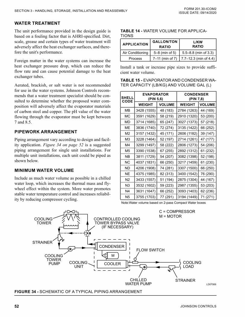
JOHNSON CONTROLS52
FORM 201.30-ICOM2ISSUE DATE: 09/14/2020SECTION 3 - HANDLING, STORAGE, INSTALLATION AND REASSEMBLY
WATER TREATMENTThe unit performance provided in the design guide is based on a fouling factor that is AHRI-specified. Dirt, scale, grease and certain types of water treatment will adversely affect the heat exchanger surfaces, and there-fore the unit's performance.
Foreign matter in the water systems can increase the heat exchanger pressure drop, which can reduce the flow rate and can cause potential damage to the heat exchanger tubes.
Aerated, brackish, or salt water is not recommended for use in the water systems. Johnson Controls recom-mends that a water treatment specialist should be con-sulted to determine whether the proposed water com-position will adversely affect the evaporator materials of carbon steel and copper. The pH value of the water flowing through the evaporator must be kept between 7 and 8.5.
PIPEWORK ARRANGEMENTPiping arrangement vary according to design and facil-ity application. Figure 34 on page 52 is a suggested piping arrangement for single unit installations. For multiple unit installations, each unit could be piped as shown below.
MINIMUM WATER VOLUMEInclude as much water volume as possible in a chilled water loop, which increases the thermal mass and fly-wheel effect within the system. More water promotes stable water temperature control and increases reliabil-ity by reducing compressor cycling.
TABLE 14 - WATER VOLUME FOR APPLICA-TIONS
APPLICATIONGALLON/TON
RATIOL/KW RATIO
Air Conditioning 5–8 (min of 5) 5.5–8.8 (min of 3.3)Process 7–11 (min of 7) 7.7–12.3 (min of 4.4)
Install a tank or increase pipe sizes to provide suffi-cient water volume.
TABLE 15 - EVAPORATOR AND CONDENSER WA-TER CAPACITY (LB/KG) AND VOLUME GAL (L)
SHELL CODE
EVAPORATOR(PIN 5,6)
CONDENSER(PIN 7,8)
WEIGHT VOLUME WEIGHT VOLUMEMB 3428 (1555) 48 (183) 2784 (1263) 44 (169)MC 3591 (1629) 58 (219) 2910 (1320) 53 (200)MD 3714 (1685) 65 (247) 3027 (1373) 57 (218)ME 3836 (1740) 72 (274) 3135 (1422) 66 (252)M2 3157 (1432) 45 (171) 2606 (1182) 39 (147)M3 3228 (1464) 52 (197) 2714 (1261) 47 (177)M4 3299 (1497) 58 (222) 2806 (1273) 54 (206)M5 3390 (1538) 67 (255) 2892 (1312) 61 (232)NB 3811 (1729) 54 (207) 3082 (1398) 52 (198)NC 4037 (1831) 66 (250) 3217 (1459) 61 (230)ND 4206 (1908) 74 (281) 3307 (1500) 66 (250)NE 4375 (1985) 82 (313) 3400 (1542) 76 (290)N2 3433 (1557) 51 (194) 2875 (1304) 44 (167)N3 3532 (1602) 59 (223) 2987 (1355) 53 (203)N4 3631 (1647) 66 (252) 3093 (1403) 62 (236)N5 3755 (1703) 77 (291) 3194 (1449) 71 (271)
Note:Water volume based on 2-pass Compact Water boxes
LD07069
COOLING TOWER
STRAINER
COOLING TOWER PUMP COOLING
UNIT
CONTROLLED COOLING TOWER BYPASS VALVE
(IF NECESSARY)
FLOW SWITCH
C = COMPRESSORM = MOTOR
CONDENSER
COOLER
C M
CHILLEDWATER PUMP
STRAINER
COOLING LOAD
FIGURE 34 - SCHEMATIC OF A TYPICAL PIPING ARRANGEMENT
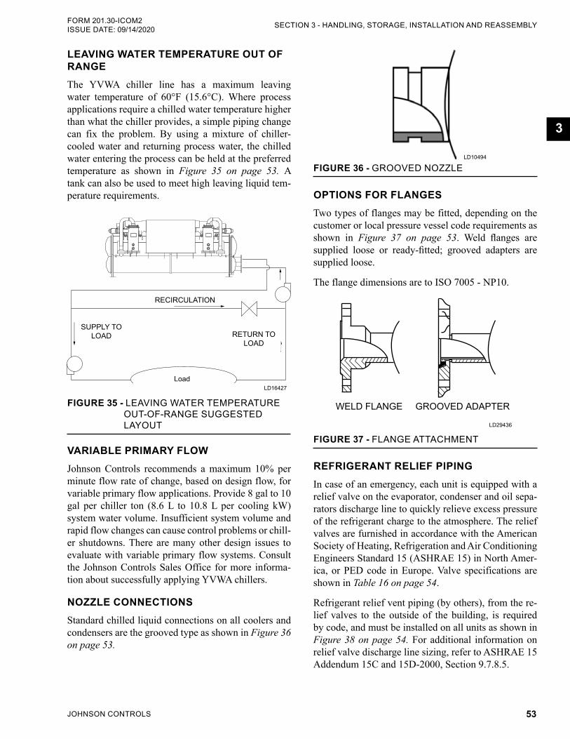
JOHNSON CONTROLS 53
SECTION 3 - HANDLING, STORAGE, INSTALLATION AND REASSEMBLYFORM 201.30-ICOM2 ISSUE DATE: 09/14/2020
3
LEAVING WATER TEMPERATURE OUT OF RANGEThe YVWA chiller line has a maximum leaving water temperature of 60°F (15.6°C). Where process applications require a chilled water temperature higher than what the chiller provides, a simple piping change can fix the problem. By using a mixture of chiller-cooled water and returning process water, the chilled water entering the process can be held at the preferred temperature as shown in Figure 35 on page 53. A tank can also be used to meet high leaving liquid tem-perature requirements.
Supply to Load
Return to Load
Load
Recirculation
SUPPLY TO LOAD
RECIRCULATION
LD16427
FIGURE 35 - LEAVING WATER TEMPERATURE OUT-OF-RANGE SUGGESTED LAYOUT
RETURN TO LOAD
VARIABLE PRIMARY FLOW Johnson Controls recommends a maximum 10% per minute flow rate of change, based on design flow, for variable primary flow applications. Provide 8 gal to 10 gal per chiller ton (8.6 L to 10.8 L per cooling kW) system water volume. Insufficient system volume and rapid flow changes can cause control problems or chill-er shutdowns. There are many other design issues to evaluate with variable primary flow systems. Consult the Johnson Controls Sales Office for more informa-tion about successfully applying YVWA chillers.
NOZZLE CONNECTIONSStandard chilled liquid connections on all coolers and condensers are the grooved type as shown in Figure 36 on page 53.
FIGURE 36 - GROOVED NOZZLELD10494
OPTIONS FOR FLANGESTwo types of flanges may be fitted, depending on the customer or local pressure vessel code requirements as shown in Figure 37 on page 53. Weld flanges are supplied loose or ready-fitted; grooved adapters are supplied loose.
The flange dimensions are to ISO 7005 - NP10.
WELD FLANGE GROOVED ADAPTER
LD29436
FIGURE 37 - FLANGE ATTACHMENT
REFRIGERANT RELIEF PIPING In case of an emergency, each unit is equipped with a relief valve on the evaporator, condenser and oil sepa-rators discharge line to quickly relieve excess pressure of the refrigerant charge to the atmosphere. The relief valves are furnished in accordance with the American Society of Heating, Refrigeration and Air Conditioning Engineers Standard 15 (ASHRAE 15) in North Amer-ica, or PED code in Europe. Valve specifications are shown in Table 16 on page 54.
Refrigerant relief vent piping (by others), from the re-lief valves to the outside of the building, is required by code, and must be installed on all units as shown in Figure 38 on page 54. For additional information on relief valve discharge line sizing, refer to ASHRAE 15 Addendum 15C and 15D-2000, Section 9.7.8.5.
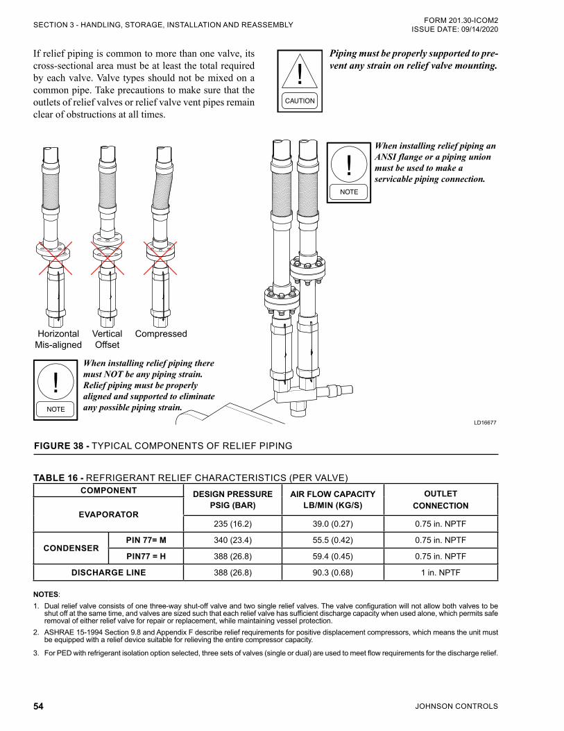
JOHNSON CONTROLS54
FORM 201.30-ICOM2ISSUE DATE: 09/14/2020SECTION 3 - HANDLING, STORAGE, INSTALLATION AND REASSEMBLY
If relief piping is common to more than one valve, its cross-sectional area must be at least the total required by each valve. Valve types should not be mixed on a common pipe. Take precautions to make sure that the outlets of relief valves or relief valve vent pipes remain clear of obstructions at all times.
When installing relief piping there must NOT be any piping strain. Relief piping must be properly aligned and supported to eliminate any possible piping strain.
When installing relief piping an ANSI flange or a piping union must be used to make a servicable piping connection.
HorizontalMis-aligned
VerticalOffset
Compressed
LD16677
FIGURE 38 - TYPICAL COMPONENTS OF RELIEF PIPING
TABLE 16 - REFRIGERANT RELIEF CHARACTERISTICS (PER VALVE)COMPONENT DESIGN PRESSURE
PSIG (BAR)AIR FLOW CAPACITY
LB/MIN (KG/S)OUTLET
CONNECTIONEVAPORATOR
235 (16.2) 39.0 (0.27) 0.75 in. NPTF
CONDENSERPIN 77= M 340 (23.4) 55.5 (0.42) 0.75 in. NPTF
PIN77 = H 388 (26.8) 59.4 (0.45) 0.75 in. NPTF
DISCHARGE LINE 388 (26.8) 90.3 (0.68) 1 in. NPTF
NOTES:1. Dual relief valve consists of one three-way shut-off valve and two single relief valves. The valve configuration will not allow both valves to be
shut off at the same time, and valves are sized such that each relief valve has sufficient discharge capacity when used alone, which permits safe removal of either relief valve for repair or replacement, while maintaining vessel protection.
2. ASHRAE 15-1994 Section 9.8 and Appendix F describe relief requirements for positive dis placement compressors, which means the unit must be equipped with a relief device suitable for relieving the entire compressor capacity.
3. For PED with refrigerant isolation option selected, three sets of valves (single or dual) are used to meet flow requirements for the discharge relief.
Piping must be properly supported to pre-vent any strain on relief valve mounting.
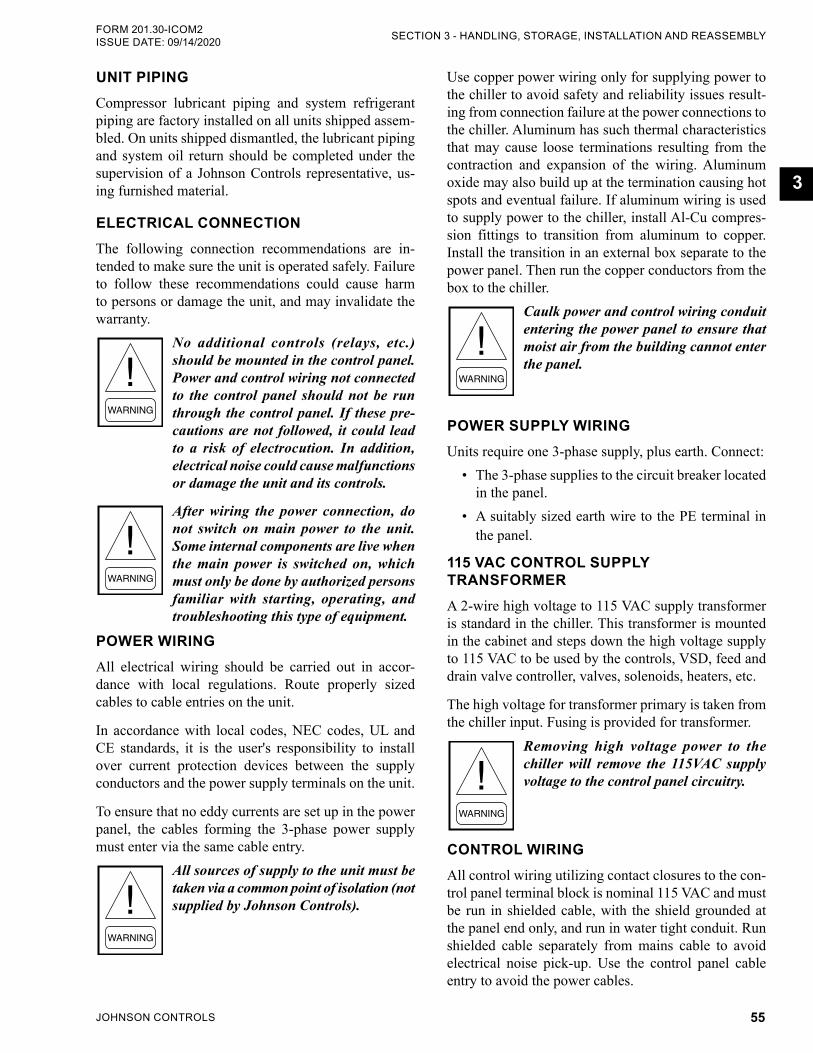
JOHNSON CONTROLS 55
SECTION 3 - HANDLING, STORAGE, INSTALLATION AND REASSEMBLYFORM 201.30-ICOM2 ISSUE DATE: 09/14/2020
3
UNIT PIPINGCompressor lubricant piping and system refrigerant piping are factory installed on all units shipped assem-bled. On units shipped dismantled, the lubricant piping and system oil return should be completed under the supervision of a Johnson Controls representative, us-ing furnished material.
ELECTRICAL CONNECTIONThe following connection recommendations are in-tended to make sure the unit is operated safely. Failure to follow these recommendations could cause harm to persons or damage the unit, and may invalidate the warranty.
No additional controls (relays, etc.) should be mounted in the control panel. Power and control wiring not connected to the control panel should not be run through the control panel. If these pre-cautions are not followed, it could lead to a risk of electrocution. In addition, electrical noise could cause malfunctions or damage the unit and its controls.
After wiring the power connection, do not switch on main power to the unit. Some internal components are live when the main power is switched on, which must only be done by authorized persons familiar with starting, operating, and troubleshooting this type of equipment.
POWER WIRINGAll electrical wiring should be carried out in accor-dance with local regulations. Route properly sized cables to cable entries on the unit.
In accordance with local codes, NEC codes, UL and CE standards, it is the user's responsibility to install over current protection devices between the supply conductors and the power supply terminals on the unit.
To ensure that no eddy currents are set up in the power panel, the cables forming the 3-phase power supply must enter via the same cable entry.
All sources of supply to the unit must be taken via a common point of isolation (not supplied by Johnson Controls).
Use copper power wiring only for supplying power to the chiller to avoid safety and reliability issues result-ing from connection failure at the power connections to the chiller. Aluminum has such thermal characteristics that may cause loose terminations resulting from the contraction and expansion of the wiring. Aluminum oxide may also build up at the termination causing hot spots and eventual failure. If aluminum wiring is used to supply power to the chiller, install Al-Cu compres-sion fittings to transition from aluminum to copper. Install the transition in an external box separate to the power panel. Then run the copper conductors from the box to the chiller.
Caulk power and control wiring conduit entering the power panel to ensure that moist air from the building cannot enter the panel.
POWER SUPPLY WIRINGUnits require one 3-phase supply, plus earth. Connect:
• The 3-phase supplies to the circuit breaker located in the panel.
• A suitably sized earth wire to the PE terminal in the panel.
115 VAC CONTROL SUPPLY TRANSFORMERA 2-wire high voltage to 115 VAC supply transformer is standard in the chiller. This transformer is mounted in the cabinet and steps down the high voltage supply to 115 VAC to be used by the controls, VSD, feed and drain valve controller, valves, solenoids, heaters, etc.
The high voltage for transformer primary is taken from the chiller input. Fusing is provided for transformer.
Removing high voltage power to the chiller will remove the 115VAC supply voltage to the control panel circuitry.
CONTROL WIRINGAll control wiring utilizing contact closures to the con-trol panel terminal block is nominal 115 VAC and must be run in shielded cable, with the shield grounded at the panel end only, and run in water tight conduit. Run shielded cable separately from mains cable to avoid electrical noise pick-up. Use the control panel cable entry to avoid the power cables.
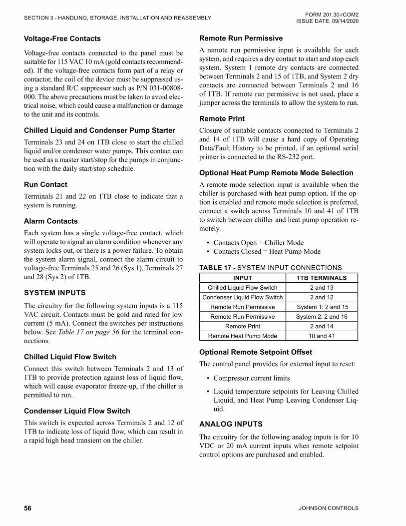
JOHNSON CONTROLS56
FORM 201.30-ICOM2ISSUE DATE: 09/14/2020SECTION 3 - HANDLING, STORAGE, INSTALLATION AND REASSEMBLY
Voltage-Free Contacts
Voltage-free contacts connected to the panel must be suitable for 115 VAC 10 mA (gold contacts recommend-ed). If the voltage-free contacts form part of a relay or contactor, the coil of the device must be suppressed us-ing a standard R/C suppressor such as P/N 031-00808-000. The above precautions must be taken to avoid elec-trical noise, which could cause a malfunction or damage to the unit and its controls.
Chilled Liquid and Condenser Pump StarterTerminals 23 and 24 on 1TB close to start the chilled liquid and/or condenser water pumps. This contact can be used as a master start/stop for the pumps in conjunc-tion with the daily start/stop schedule.
Run ContactTerminals 21 and 22 on 1TB close to indicate that a system is running.
Alarm ContactsEach system has a single voltage-free contact, which will operate to signal an alarm condition whenever any system locks out, or there is a power failure. To obtain the system alarm signal, connect the alarm circuit to voltage-free Terminals 25 and 26 (Sys 1), Terminals 27 and 28 (Sys 2) of 1TB.
SYSTEM INPUTSThe circuitry for the following system inputs is a 115 VAC circuit. Contacts must be gold and rated for low current (5 mA). Connect the switches per instructions below. See Table 17 on page 56 for the terminal con-nections.
Chilled Liquid Flow SwitchConnect this switch between Terminals 2 and 13 of 1TB to provide protection against loss of liquid flow, which will cause evaporator freeze-up, if the chiller is permitted to run.
Condenser Liquid Flow SwitchThis switch is expected across Terminals 2 and 12 of 1TB to indicate loss of liquid flow, which can result in a rapid high head transient on the chiller.
Remote Run PermissiveA remote run permissive input is available for each system, and requires a dry contact to start and stop each system. System 1 remote dry contacts are connected between Terminals 2 and 15 of 1TB, and System 2 dry contacts are connected between Terminals 2 and 16 of 1TB. If remote run permissive is not used, place a jumper across the terminals to allow the system to run.
Remote PrintClosure of suitable contacts connected to Terminals 2 and 14 of 1TB will cause a hard copy of Operating Data/Fault History to be printed, if an optional serial printer is connected to the RS-232 port.
Optional Heat Pump Remote Mode SelectionA remote mode selection input is available when the chiller is purchased with heat pump option. If the op-tion is enabled and remote mode selection is preferred, connect a switch across Terminals 10 and 41 of 1TB to switch between chiller and heat pump operation re-motely.
• Contacts Open = Chiller Mode • Contacts Closed = Heat Pump Mode
TABLE 17 - SYSTEM INPUT CONNECTIONSINPUT 1TB TERMINALS
Chilled Liquid Flow Switch 2 and 13Condenser Liquid Flow Switch 2 and 12
Remote Run Permissive System 1: 2 and 15Remote Run Permissive System 2: 2 and 16
Remote Print 2 and 14Remote Heat Pump Mode 10 and 41
Optional Remote Setpoint OffsetThe control panel provides for external input to reset:
• Compressor current limits
• Liquid temperature setpoints for Leaving Chilled Liquid, and Heat Pump Leaving Condenser Liq-uid.
ANALOG INPUTSThe circuitry for the following analog inputs is for 10 VDC or 20 mA current inputs when remote setpoint control options are purchased and enabled.
JOHNSON CONTROLS 57
SECTION 3 - HANDLING, STORAGE, INSTALLATION AND REASSEMBLYFORM 201.30-ICOM2 ISSUE DATE: 09/14/2020
3
Leaving Chilled Liquid Temperature Reset ControlInstall input for Leaving Chilled Liquid Temperature Control remote reset across Terminals 17 (+) and 18 (-) of the 1TB Terminal Block.
How to Receive Voltage or Current SignalThe control board JUMPER JP4 must be positioned correctly to receive a voltage (0 VDC to 10 VDC or 2 VDC to 10 VDC) or a current (0 mA to 20 mA or 4 mA to 20 mA) signal. Place the jumper in the V position for a voltage signal, or mA for a current signal. Configure the software under the OPTIONS key for the specific type of input signal to be used.
The maximum temperature reset (100%) is achieved at either 10 VDC or 20 mA. Sending the minimum signal (0 VDC or 2 VDC, 0 mA or 4 mA, based on the OP-TIONS key) causes the setpoint to revert back to its lo-cal programmed value. If the setpoint reset causes the setpoint to go over the maximum programmable value, it will be set to the maximum programmable setpoint.
0 VDC to 10 VDC or 2 VDC to 10 VDC Reset InputA 0 VDC or 2 VDC signal produces a 0°F (0°C) re-set. A 10 VDC signal produces a 100% (max.) reset (SETPOINTS key). The setpoint reset is ramped lin-early between these limits as the input varies between 0 VDC or 2 VDC and 10 VDC. For this input to work properly, the Remote Temperature Reset must be pro-grammed for 0 VDC to 10 VDC or 2 VDC to 10 VDC input (OPTIONS key) and control board JUMPER JP4 placed in the V position.
0 mA to 20 or 4 mA to 20 mA Reset InputA 0 mA or 4 mA signal produces a 0°F (0°C) reset. A 20 mA signal produces 100% (max.) reset (SETPOINTS key). The setpoint reset is ramped linearly between these limits as the input varies between 0 mA or 4 mA and 20 mA. In order for this input to work properly, program the Remote Temperature Reset for 0 mA to 20 mA or 4 mA to 20 mA input (OPTIONS) and control board JUMPER JP4 placed in the mA position.
Leaving Condenser Liquid Temperature Reset ControlThe same input used for Leaving Chilled Liquid Tem-perature Reset is used for Leaving Condenser Liquid Temperature Reset when the heat pump option is in-
stalled. The function of the input is controlled by se-lecting the operating mode described in SECTION 6 - OPERATION in this manual.
Current Limit Reset ControlInstall input for Current Limit Reset Control across Terminals 19 (+) and 20 (-) of the 1TB Terminal Block.
How to Receive Voltage or Current SignalThe control board JUMPER JP5 must be positioned correctly to receive a voltage (0 VDC to 10 VDC or 2 VDC to 10 VDC) or a current (0 mA to 20 mA or 4 mA to 20 mA) signal. Place the jumper in the V position for a voltage signal or mA for a current signal. Configure the software under the OPTIONS key for the type of input signal to be used.
The minimum current limit setpoint is achieved at ei-ther 10 VDC or 20 mA. Sending the minimum signal (0 VDC or 2 VDC, 0 mA or 4 mA, based on the OP-TIONS key) causes the current limit to revert back to its maximum value.
0 VDC to 10 or 2 VDC to 10 VDC Reset InputA 0 VDC or 2 VDC signal produces a 0°F (0°C) re-set. A 10 VDC signal produces a 100% (max.) reset (SETPOINTS key). The setpoint reset is ramped lin-early between these limits as the input varies between 0 VDC or 2 VDC and 10 VDC. In order for this input to work properly, the Remote Temperature Reset must be programmed for 0 VDC to 10 VDC or 2 VDC to 10 VDC input (OPTIONS key) and control board JUMP-ER JP5 placed in the V position.
0 mA to 20 mA or 4 mA to 20 mA Reset InputA 0 mA or 4 mA signal produces a 0°F (0°C) reset. A 20 mA signal produces 100% (max.) reset (SETPOINTS key). The setpoint reset is ramped linearly between these limits as the input varies between 0 mA or 4 mA and 20 mA. In order for this input to work properly, the program the Remote Temperature Reset for 0 mA to 20 mA or 4 mA to 20 mA input (OPTIONS key) and control board JUMPER JP5 placed in the mA position.
INSTALLATION CHECKLIST – REQUEST FOR START-UP SERVICE
When all items on the Installation Checklist and Request for Authorized Start-up Technician (Form 201.30-CL1) are completed satisfactorily, and before any attempt is made to start the unit, contact the John-son Controls Field Service Office to schedule the start-up service.
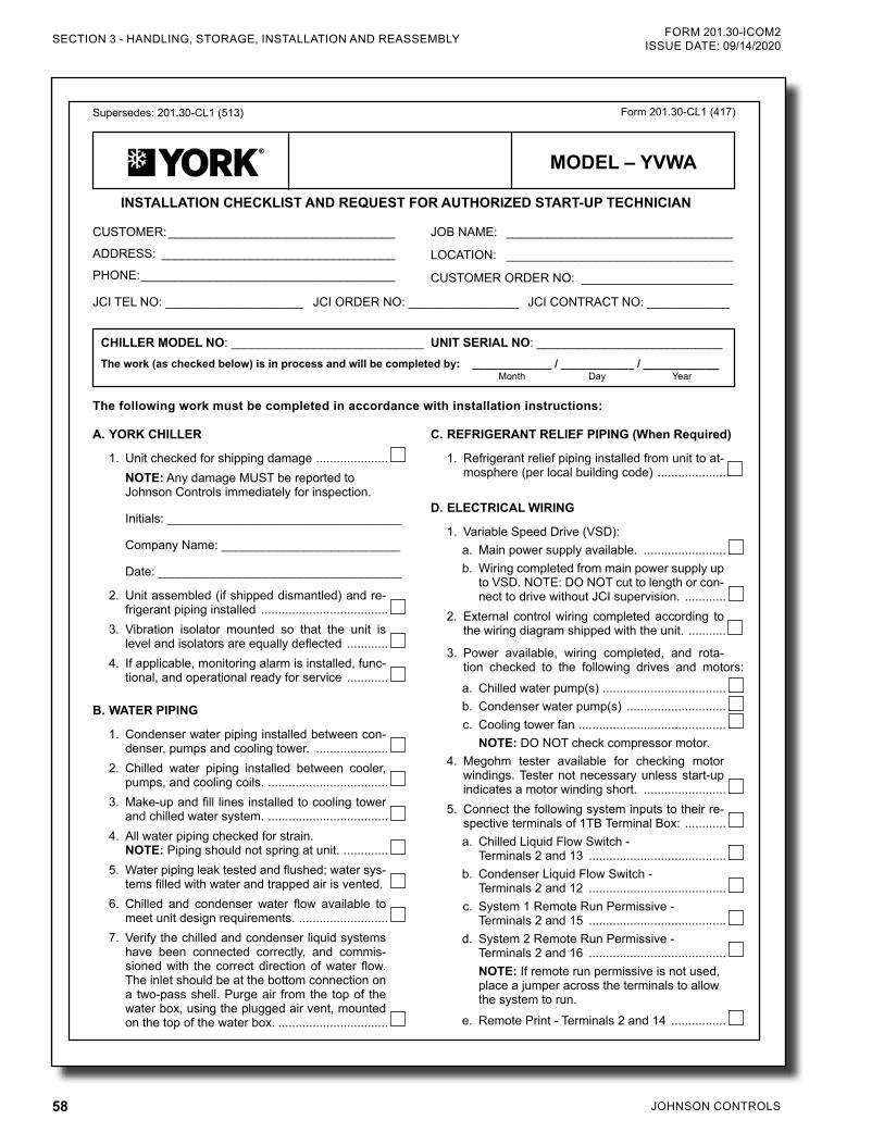
JOHNSON CONTROLS58
FORM 201.30-ICOM2ISSUE DATE: 09/14/2020SECTION 3 - HANDLING, STORAGE, INSTALLATION AND REASSEMBLY
Supersedes: 201.30-CL1 (513)
INSTALLATION CHECKLIST AND REQUEST FOR AUTHORIZED START-UP TECHNICIAN
Form 201.30-CL1 (417)
The following work must be completed in accordance with installation instructions:
CUSTOMER: _________________________________
ADDRESS: __________________________________
PHONE: _____________________________________
JCI TEL NO: ____________________ JCI ORDER NO: ________________ JCI CONTRACT NO: ____________
JOB NAME: _________________________________
LOCATION: _________________________________
CUSTOMER ORDER NO: ______________________
CHILLER MODEL NO: ____________________________
The work (as checked below) is in process and will be completed by: _____________ / ____________ / ___________UNIT SERIAL NO: ___________________________
Month Day Year
C. REFRIGERANT RELIEF PIPING (When Required)
1. Refrigerant relief piping installed from unit to at-mosphere (per local building code) ....................
D. ELECTRICAL WIRING
1. Variable Speed Drive (VSD):a. Main power supply available. ........................b. Wiring completed from main power supply up
to VSD. NOTE: DO NOT cut to length or con-nect to drive without JCI supervision. ............
2. External control wiring completed according to the wiring diagram shipped with the unit. ...........
3. Power available, wiring completed, and rota-tion checked to the following drives and motors:
a. Chilled water pump(s) ....................................b. Condenser water pump(s) .............................c. Cooling tower fan ...........................................
NOTE: DO NOT check compressor motor. 4. Megohm tester available for checking motor
windings. Tester not necessary unless start-up indicates a motor winding short. ........................
5. Connect the following system inputs to their re-spective terminals of 1TB Terminal Box: ............a. Chilled Liquid Flow Switch -
Terminals 2 and 13 ........................................b. Condenser Liquid Flow Switch -
Terminals 2 and 12 ........................................c. System 1 Remote Run Permissive -
Terminals 2 and 15 ........................................d. System 2 Remote Run Permissive -
Terminals 2 and 16 ........................................NOTE: If remote run permissive is not used, place a jumper across the terminals to allow the system to run.
e. Remote Print - Terminals 2 and 14 ................
A. YORK CHILLER
1. Unit checked for shipping damage .....................NOTE: Any damage MUST be reported to Johnson Controls immediately for inspection.
Initials: __________________________________
Company Name: __________________________
Date: ____________________________________
2. Unit assembled (if shipped dismantled) and re-frigerant piping installed .....................................
3. Vibration isolator mounted so that the unit is level and isolators are equally deflected ............
4. If applicable, monitoring alarm is installed, func-tional, and operational ready for service ............
B. WATER PIPING
1. Condenser water piping installed between con-denser, pumps and cooling tower. .....................
2. Chilled water piping installed between cooler, pumps, and cooling coils. ...................................
3. Make-up and fill lines installed to cooling tower and chilled water system. ...................................
4. All water piping checked for strain. NOTE: Piping should not spring at unit. . ............
5. Water piping leak tested and flushed; water sys-tems filled with water and trapped air is vented.
6. Chilled and condenser water flow available to meet unit design requirements. ..........................
7. Verify the chilled and condenser liquid systems have been connected correctly, and commis-sioned with the correct direction of water flow. The inlet should be at the bottom connection on a two-pass shell. Purge air from the top of the water box, using the plugged air vent, mounted on the top of the water box. ................................
MODEL – YVWA
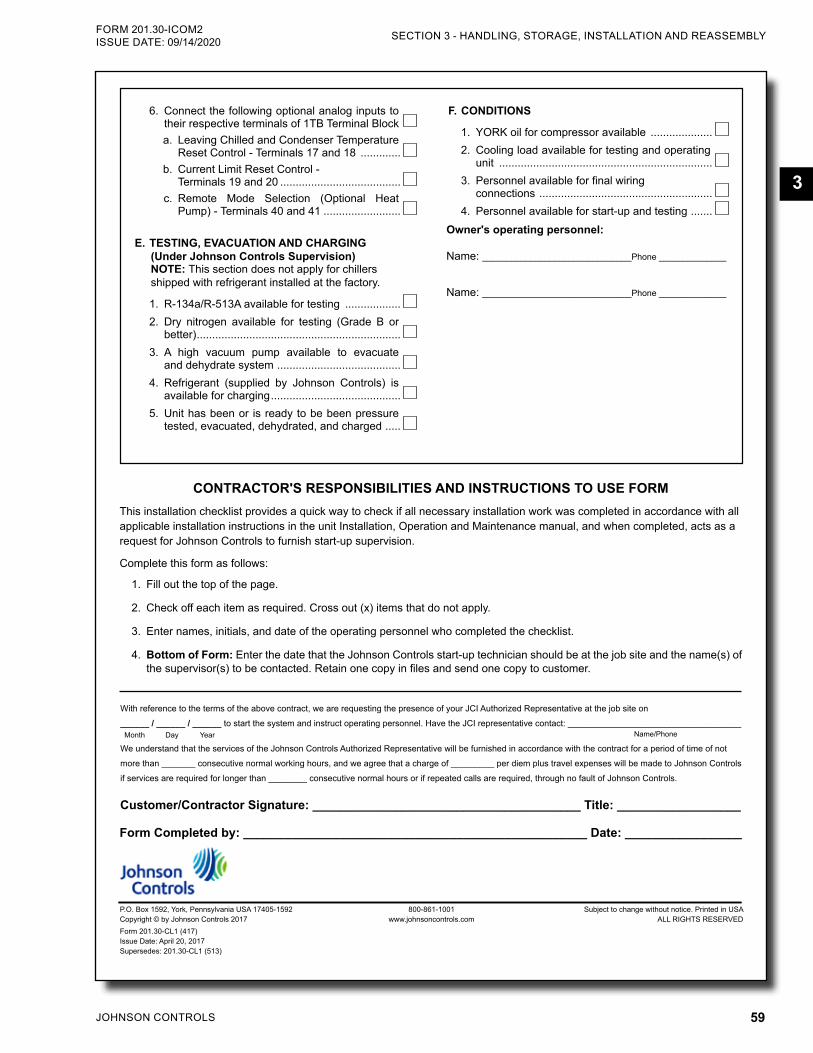
JOHNSON CONTROLS 59
SECTION 3 - HANDLING, STORAGE, INSTALLATION AND REASSEMBLYFORM 201.30-ICOM2 ISSUE DATE: 09/14/2020
3
FORM 201.30-CL1ISSUE DATE: 4/20/2017
P.O. Box 1592, York, Pennsylvania USA 17405-1592 800-861-1001 Subject to change without notice. Printed in USACopyright © by Johnson Controls 2017 www.johnsoncontrols.com ALL RIGHTS RESERVEDForm 201.30-CL1 (417)Issue Date: April 20, 2017 Supersedes: 201.30-CL1 (513)
6. Connect the following optional analog inputs to their respective terminals of 1TB Terminal Block a. Leaving Chilled and Condenser Temperature
Reset Control - Terminals 17 and 18 .............b. Current Limit Reset Control -
Terminals 19 and 20 .......................................c. Remote Mode Selection (Optional Heat
Pump) - Terminals 40 and 41 .........................
E. TESTING, EVACUATION AND CHARGING (Under Johnson Controls Supervision) NOTE: This section does not apply for chillers shipped with refrigerant installed at the factory.
1. R-134a/R-513A available for testing ..................2. Dry nitrogen available for testing (Grade B or
better) ..................................................................3. A high vacuum pump available to evacuate
and dehydrate system ........................................4. Refrigerant (supplied by Johnson Controls) is
available for charging ..........................................5. Unit has been or is ready to be been pressure
tested, evacuated, dehydrated, and charged .....
F. CONDITIONS
1. YORK oil for compressor available ....................2. Cooling load available for testing and operating
unit .....................................................................3. Personnel available for final wiring
connections ........................................................4. Personnel available for start-up and testing .......
Owner's operating personnel:
Name: _______________________________Phone ______________
Name: _______________________________Phone ______________
With reference to the terms of the above contract, we are requesting the presence of your JCI Authorized Representative at the job site on
______ / ______ / ______ to start the system and instruct operating personnel. Have the JCI representative contact: ____________________________________
We understand that the services of the Johnson Controls Authorized Representative will be furnished in accordance with the contract for a period of time of not
more than _______ consecutive normal working hours, and we agree that a charge of _________ per diem plus travel expenses will be made to Johnson Controls
if services are required for longer than ________ consecutive normal hours or if repeated calls are required, through no fault of Johnson Controls.
Month Day Year Name/Phone
Customer/Contractor Signature: _______________________________________ Title: __________________
Form Completed by: __________________________________________________ Date: _________________
CONTRACTOR'S RESPONSIBILITIES AND INSTRUCTIONS TO USE FORMThis installation checklist provides a quick way to check if all necessary installation work was completed in accordance with all applicable installation instructions in the unit Installation, Operation and Maintenance manual, and when completed, acts as a request for Johnson Controls to furnish start-up supervision.
Complete this form as follows:
1. Fill out the top of the page.
2. Check off each item as required. Cross out (x) items that do not apply.
3. Enter names, initials, and date of the operating personnel who completed the checklist.
4. Bottom of Form: Enter the date that the Johnson Controls start-up technician should be at the job site and the name(s) of the supervisor(s) to be contacted. Retain one copy in files and send one copy to customer.
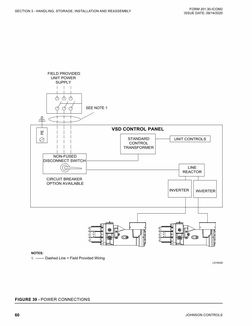
JOHNSON CONTROLS60
FORM 201.30-ICOM2ISSUE DATE: 09/14/2020SECTION 3 - HANDLING, STORAGE, INSTALLATION AND REASSEMBLY
FIGURE 39 - POWER CONNECTIONS
VSD CONTROL PANEL
STANDARDCONTROL
TRANSFORMER
UNIT CONTROLS
PE
LINEREACTOR
CIRCUIT BREAKER OPTION AVAILABLE
FIELD PROVIDEDUNIT POWER
SUPPLY
SEE NOTE 1
NON-FUSEDDISCONNECT SWITCH
NOTES:1. ------- Dashed Line = Field Provided Wiring
INVERTER INVERTER
LD16428
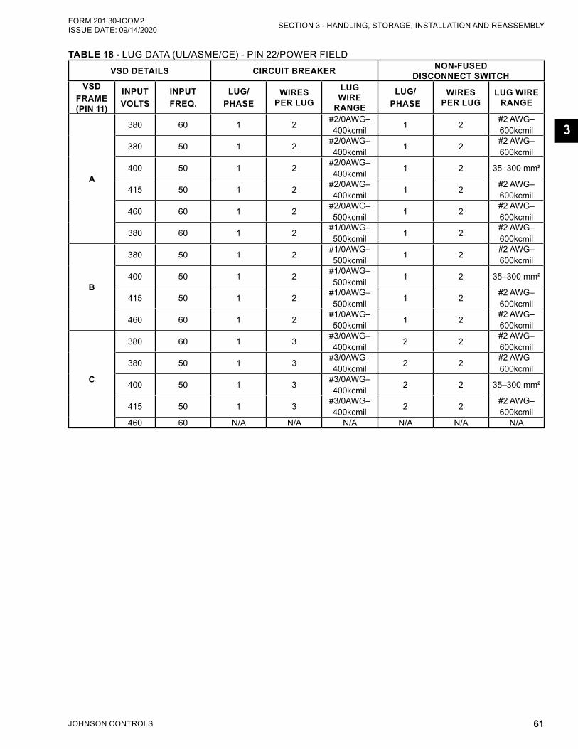
JOHNSON CONTROLS 61
SECTION 3 - HANDLING, STORAGE, INSTALLATION AND REASSEMBLYFORM 201.30-ICOM2 ISSUE DATE: 09/14/2020
3
TABLE 18 - LUG DATA (UL/ASME/CE) - PIN 22/POWER FIELDVSD DETAILS CIRCUIT BREAKER NON-FUSED
DISCONNECT SWITCHVSD
FRAME (PIN 11)
INPUTVOLTS
INPUT FREQ.
LUG/PHASE
WIRES PER LUG
LUG WIRE
RANGE
LUG/PHASE
WIRES PER LUG
LUG WIRE RANGE
A
380 60 1 2 #2/0AWG–400kcmil 1 2 #2 AWG–
600kcmil
380 50 1 2 #2/0AWG–400kcmil 1 2 #2 AWG–
600kcmil
400 50 1 2 #2/0AWG–400kcmil 1 2 35–300 mm²
415 50 1 2 #2/0AWG–400kcmil 1 2 #2 AWG–
600kcmil
460 60 1 2 #2/0AWG–500kcmil 1 2 #2 AWG–
600kcmil
380 60 1 2 #1/0AWG–500kcmil 1 2 #2 AWG–
600kcmil
B
380 50 1 2 #1/0AWG–500kcmil 1 2 #2 AWG–
600kcmil
400 50 1 2 #1/0AWG–500kcmil 1 2 35–300 mm²
415 50 1 2 #1/0AWG–500kcmil 1 2 #2 AWG–
600kcmil
460 60 1 2 #1/0AWG–500kcmil 1 2 #2 AWG–
600kcmil
C
380 60 1 3 #3/0AWG–400kcmil 2 2 #2 AWG–
600kcmil
380 50 1 3 #3/0AWG–400kcmil 2 2 #2 AWG–
600kcmil
400 50 1 3 #3/0AWG–400kcmil 2 2 35–300 mm²
415 50 1 3 #3/0AWG–400kcmil 2 2 #2 AWG–
600kcmil460 60 N/A N/A N/A N/A N/A N/A
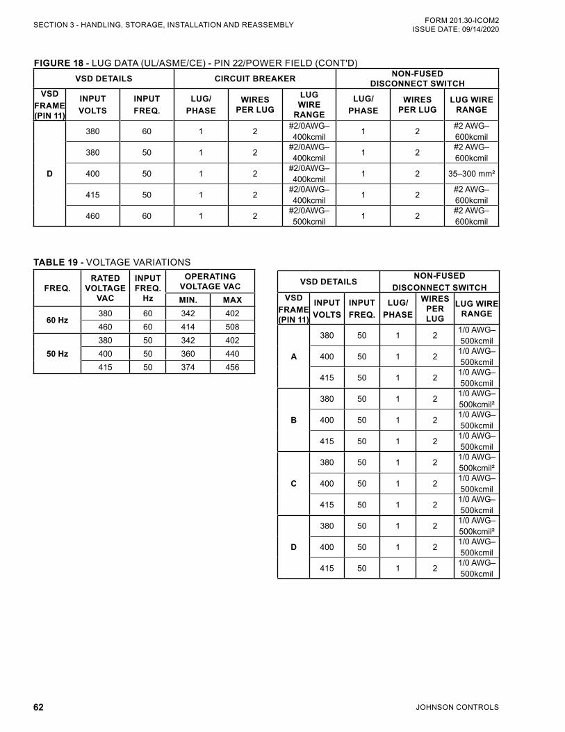
JOHNSON CONTROLS62
FORM 201.30-ICOM2ISSUE DATE: 09/14/2020SECTION 3 - HANDLING, STORAGE, INSTALLATION AND REASSEMBLY
FIGURE 18 - LUG DATA (UL/ASME/CE) - PIN 22/POWER FIELD (CONT'D)VSD DETAILS CIRCUIT BREAKER NON-FUSED
DISCONNECT SWITCHVSD
FRAME (PIN 11)
INPUTVOLTS
INPUT FREQ.
LUG/PHASE
WIRES PER LUG
LUG WIRE
RANGE
LUG/PHASE
WIRES PER LUG
LUG WIRE RANGE
D
380 60 1 2 #2/0AWG–400kcmil 1 2 #2 AWG–
600kcmil
380 50 1 2 #2/0AWG–400kcmil 1 2 #2 AWG–
600kcmil
400 50 1 2 #2/0AWG–400kcmil 1 2 35–300 mm²
415 50 1 2 #2/0AWG–400kcmil 1 2 #2 AWG–
600kcmil
460 60 1 2 #2/0AWG–500kcmil 1 2 #2 AWG–
600kcmil
VSD DETAILSNON-FUSED
DISCONNECT SWITCHVSD
FRAME (PIN 11)
INPUTVOLTS
INPUT FREQ.
LUG/PHASE
WIRES PER LUG
LUG WIRE RANGE
A
380 50 1 2 1/0 AWG–500kcmil
400 50 1 2 1/0 AWG–500kcmil
415 50 1 2 1/0 AWG–500kcmil
B
380 50 1 2 1/0 AWG–500kcmil²
400 50 1 2 1/0 AWG–500kcmil
415 50 1 2 1/0 AWG–500kcmil
C
380 50 1 2 1/0 AWG–500kcmil²
400 50 1 2 1/0 AWG–500kcmil
415 50 1 2 1/0 AWG–500kcmil
D
380 50 1 2 1/0 AWG–500kcmil²
400 50 1 2 1/0 AWG–500kcmil
415 50 1 2 1/0 AWG–500kcmil
TABLE 19 - VOLTAGE VARIATIONS
FREQ.RATED
VOLTAGE VAC
INPUT FREQ.
Hz
OPERATING VOLTAGE VACMIN. MAX
60 Hz380 60 342 402460 60 414 508
50 Hz380 50 342 402400 50 360 440415 50 374 456
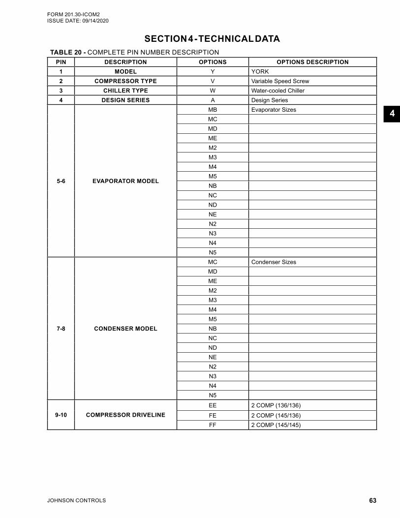
JOHNSON CONTROLS 63
FORM 201.30-ICOM2 ISSUE DATE: 09/14/2020
4
SECTION 4 - TECHNICAL DATATABLE 20 - COMPLETE PIN NUMBER DESCRIPTION
PIN DESCRIPTION OPTIONS OPTIONS DESCRIPTION1 MODEL Y YORK2 COMPRESSOR TYPE V Variable Speed Screw3 CHILLER TYPE W Water-cooled Chiller4 DESIGN SERIES A Design Series
5-6 EVAPORATOR MODEL
MB Evaporator SizesMCMDMEM2M3M4M5NBNCNDNEN2N3N4N5
7-8 CONDENSER MODEL
MC Condenser SizesMDMEM2M3M4M5NBNCNDNEN2N3N4N5
9-10 COMPRESSOR DRIVELINEEE 2 COMP (136/136)
FE 2 COMP (145/136)FF 2 COMP (145/145)
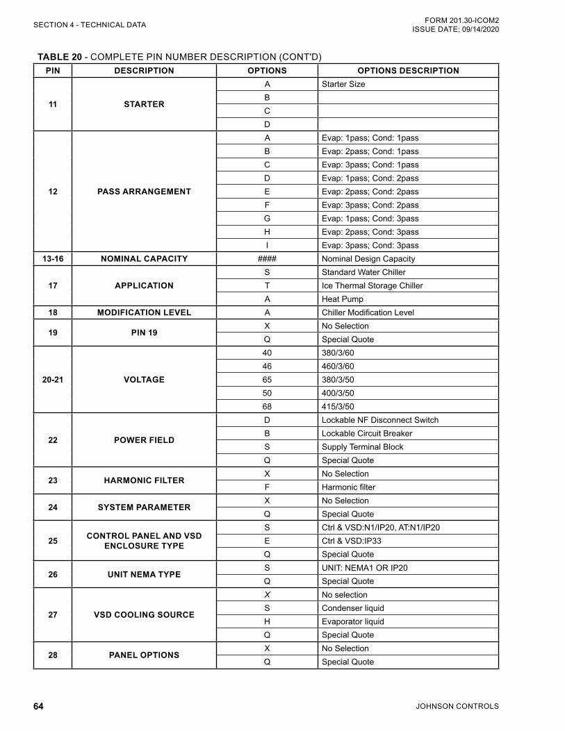
JOHNSON CONTROLS64
FORM 201.30-ICOM2ISSUE DATE: 09/14/2020SECTION 4 - TECHNICAL DATA
TABLE 20 - COMPLETE PIN NUMBER DESCRIPTION (CONT'D)PIN DESCRIPTION OPTIONS OPTIONS DESCRIPTION
11 STARTER
A Starter SizeBCD
12 PASS ARRANGEMENT
A Evap: 1pass; Cond: 1passB Evap: 2pass; Cond: 1passC Evap: 3pass; Cond: 1passD Evap: 1pass; Cond: 2passE Evap: 2pass; Cond: 2passF Evap: 3pass; Cond: 2passG Evap: 1pass; Cond: 3passH Evap: 2pass; Cond: 3passI Evap: 3pass; Cond: 3pass
13-16 NOMINAL CAPACITY #### Nominal Design Capacity
17 APPLICATIONS Standard Water ChillerT Ice Thermal Storage ChillerA Heat Pump
18 MODIFICATION LEVEL A Chiller Modification Level
19 PIN 19X No SelectionQ Special Quote
20-21 VOLTAGE
40 380/3/6046 460/3/6065 380/3/5050 400/3/5068 415/3/50
22 POWER FIELD
D Lockable NF Disconnect SwitchB Lockable Circuit BreakerS Supply Terminal BlockQ Special Quote
23 HARMONIC FILTERX No SelectionF Harmonic filter
24 SYSTEM PARAMETERX No SelectionQ Special Quote
25 CONTROL PANEL AND VSD ENCLOSURE TYPE
S Ctrl & VSD:N1/IP20, AT:N1/IP20E Ctrl & VSD:IP33Q Special Quote
26 UNIT NEMA TYPES UNIT: NEMA1 OR IP20Q Special Quote
27 VSD COOLING SOURCE
X No selectionS Condenser liquidH Evaporator liquidQ Special Quote
28 PANEL OPTIONSX No SelectionQ Special Quote

JOHNSON CONTROLS 65
SECTION 4 - TECHNICAL DATAFORM 201.30-ICOM2 ISSUE DATE: 09/14/2020
4
TABLE 20 - COMPLETE PIN NUMBER DESCRIPTION (CONT'D)PIN DESCRIPTION OPTIONS OPTIONS DESCRIPTION
29 BAS RESET / OFFSET
X No SelectionB BAS/EMS Temp, Cur Reset/OffsetC BAS/EMS Current Reset/OffsetT BAS/EMS Temp Reset/OffsetA BACnet Elink (factory mounted)M Modbus Elink (factory mounted)L LON Elink (factory mounted)N N2 Elink (factory mounted)Q Special Quote
30 LANGUAGE/DISPLAY
A EnglishF FrenchS SpanishG GermanP PortugueseI ItalianH HungarianL PolishE Chinese, SimplifiedQ Special Quote
31 SAFETY CODE
G Chinese Safety Code (GB)C European Safety Code (CE)L NA Safety Code (cUL/cETL)Q Special Quote
32-35 FUTURE OPTIONSX No SelectionQ Special Quote
36 PIPING CODEX Single relief valveR Dual relief valvesQ Special Quote
37 FUTURE OPTIONSX No SelectionQ Special Quote
38 VALVE OPTIONSX N/AB Condenser isolation valvesQ Special Quote
39 HOT GAS BYPASSX No SelectionQ Special Quote
40 LIQUID INJECTION KITX No SelectionL Liquid injection kitQ Special Quote
41 REFRIGERANT A R134a
42 COMPRESSOR VARIATION
W Standard compressorS High head compressorV Optimized high head compressorQ Special Quote
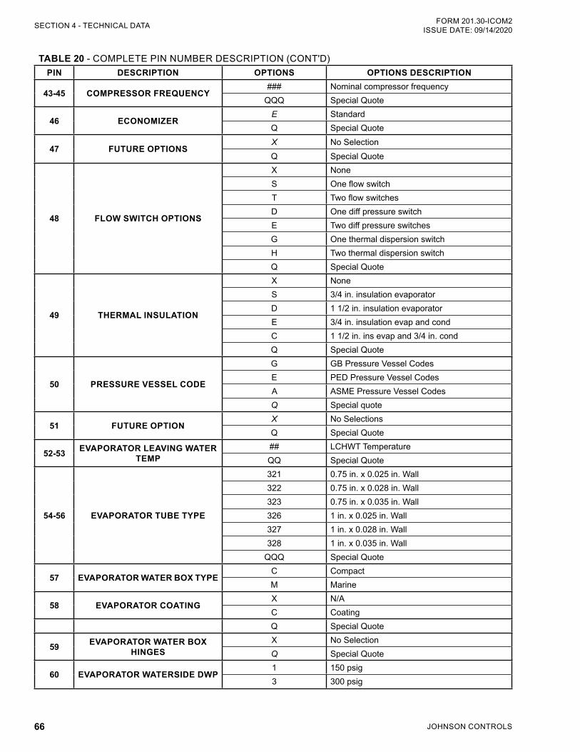
JOHNSON CONTROLS66
FORM 201.30-ICOM2ISSUE DATE: 09/14/2020SECTION 4 - TECHNICAL DATA
TABLE 20 - COMPLETE PIN NUMBER DESCRIPTION (CONT'D)PIN DESCRIPTION OPTIONS OPTIONS DESCRIPTION
43-45 COMPRESSOR FREQUENCY### Nominal compressor frequency
QQQ Special Quote
46 ECONOMIZERE StandardQ Special Quote
47 FUTURE OPTIONSX No SelectionQ Special Quote
48 FLOW SWITCH OPTIONS
X NoneS One flow switchT Two flow switchesD One diff pressure switchE Two diff pressure switchesG One thermal dispersion switchH Two thermal dispersion switchQ Special Quote
49 THERMAL INSULATION
X NoneS 3/4 in. insulation evaporatorD 1 1/2 in. insulation evaporatorE 3/4 in. insulation evap and condC 1 1/2 in. ins evap and 3/4 in. condQ Special Quote
50 PRESSURE VESSEL CODE
G GB Pressure Vessel CodesE PED Pressure Vessel CodesA ASME Pressure Vessel CodesQ Special quote
51 FUTURE OPTIONX No SelectionsQ Special Quote
52-53 EVAPORATOR LEAVING WATER TEMP
## LCHWT TemperatureQQ Special Quote
54-56 EVAPORATOR TUBE TYPE
321 0.75 in. x 0.025 in. Wall322 0.75 in. x 0.028 in. Wall323 0.75 in. x 0.035 in. Wall326 1 in. x 0.025 in. Wall327 1 in. x 0.028 in. Wall328 1 in. x 0.035 in. Wall
QQQ Special Quote
57 EVAPORATOR WATER BOX TYPEC CompactM Marine
58 EVAPORATOR COATINGX N/AC CoatingQ Special Quote
59 EVAPORATOR WATER BOX HINGES
X No SelectionQ Special Quote
60 EVAPORATOR WATERSIDE DWP1 150 psig3 300 psig
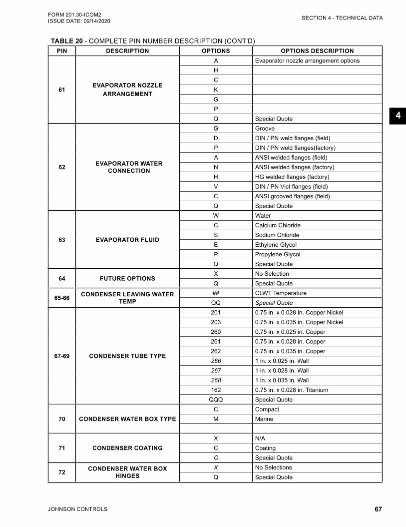
JOHNSON CONTROLS 67
SECTION 4 - TECHNICAL DATAFORM 201.30-ICOM2 ISSUE DATE: 09/14/2020
4
TABLE 20 - COMPLETE PIN NUMBER DESCRIPTION (CONT'D)PIN DESCRIPTION OPTIONS OPTIONS DESCRIPTION
61EVAPORATOR NOZZLE
ARRANGEMENT
A Evaporator nozzle arrangement optionsHCKGPQ Special Quote
62 EVAPORATOR WATER CONNECTION
G GrooveD DIN / PN weld flanges (field)P DIN / PN weld flanges(factory)A ANSI welded flanges (field)N ANSI welded flanges (factory)H HG welded flanges (factory)V DIN / PN Vict flanges (field)C ANSI grooved flanges (field)Q Special Quote
63 EVAPORATOR FLUID
W WaterC Calcium ChlorideS Sodium ChlorideE Ethylene GlycolP Propylene GlycolQ Special Quote
64 FUTURE OPTIONSX No SelectionQ Special Quote
65-66 CONDENSER LEAVING WATER TEMP
## CLWT TemperatureQQ Special Quote
67-69 CONDENSER TUBE TYPE
201 0.75 in. x 0.028 in. Copper Nickel203 0.75 in. x 0.035 in. Copper Nickel260 0.75 in. x 0.025 in. Copper 261 0.75 in. x 0.028 in. Copper262 0.75 in. x 0.035 in. Copper266 1 in. x 0.025 in. Wall267 1 in. x 0.028 in. Wall268 1 in. x 0.035 in. Wall162 0.75 in. x 0.028 in. Titanium
QQQ Special Quote
70 CONDENSER WATER BOX TYPEC CompactM Marine
71 CONDENSER COATINGX N/AC CoatingC Special Quote
72 CONDENSER WATER BOX HINGES
X No SelectionsQ Special Quote
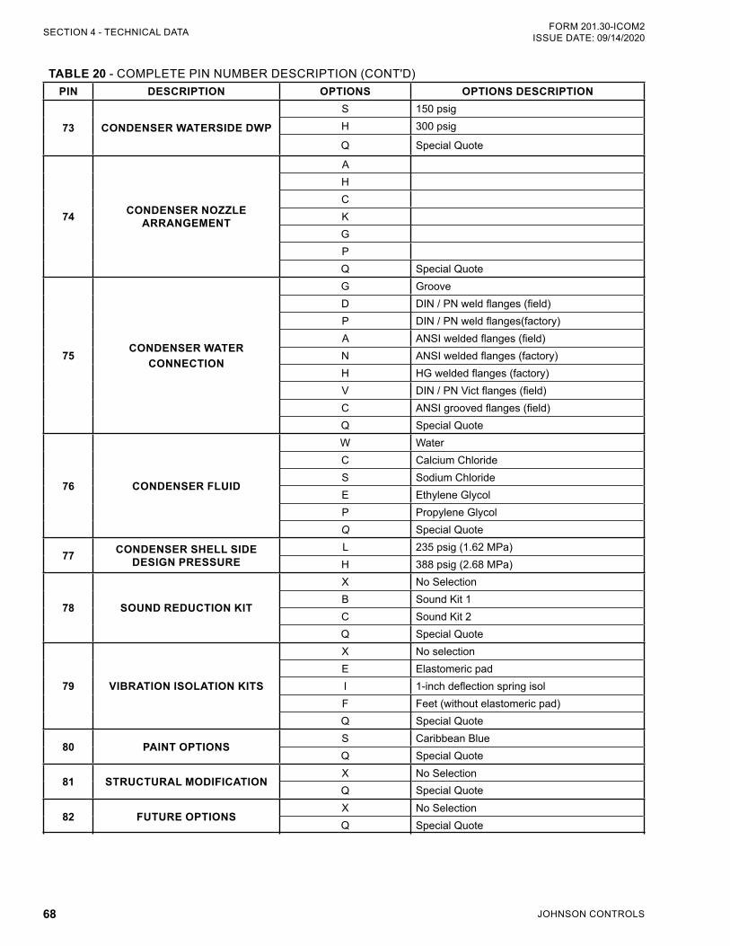
JOHNSON CONTROLS68
FORM 201.30-ICOM2ISSUE DATE: 09/14/2020SECTION 4 - TECHNICAL DATA
TABLE 20 - COMPLETE PIN NUMBER DESCRIPTION (CONT'D)PIN DESCRIPTION OPTIONS OPTIONS DESCRIPTION
73 CONDENSER WATERSIDE DWPS 150 psigH 300 psig
Q Special Quote
74 CONDENSER NOZZLE ARRANGEMENT
AHCKGPQ Special Quote
75CONDENSER WATER
CONNECTION
G GrooveD DIN / PN weld flanges (field)P DIN / PN weld flanges(factory)A ANSI welded flanges (field)N ANSI welded flanges (factory)H HG welded flanges (factory)V DIN / PN Vict flanges (field)C ANSI grooved flanges (field)Q Special Quote
76 CONDENSER FLUID
W WaterC Calcium ChlorideS Sodium ChlorideE Ethylene GlycolP Propylene GlycolQ Special Quote
77 CONDENSER SHELL SIDE DESIGN PRESSURE
L 235 psig (1.62 MPa)H 388 psig (2.68 MPa)
78 SOUND REDUCTION KIT
X No SelectionB Sound Kit 1C Sound Kit 2Q Special Quote
79 VIBRATION ISOLATION KITS
X No selectionE Elastomeric padI 1-inch deflection spring isolF Feet (without elastomeric pad)Q Special Quote
80 PAINT OPTIONSS Caribbean BlueQ Special Quote
81 STRUCTURAL MODIFICATION X No SelectionQ Special Quote
82 FUTURE OPTIONSX No SelectionQ Special Quote
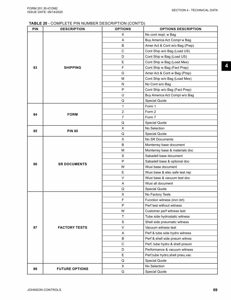
JOHNSON CONTROLS 69
SECTION 4 - TECHNICAL DATAFORM 201.30-ICOM2 ISSUE DATE: 09/14/2020
4
TABLE 20 - COMPLETE PIN NUMBER DESCRIPTION (CONT'D)PIN DESCRIPTION OPTIONS OPTIONS DESCRIPTION
83 SHIPPING
X No cont reqd, w BagA Buy America Act Compl w BagB Amer Act & Cont w/o Bag (Prep)C Cont Ship w/o Bag (Load US)D Cont Ship w Bag (Load US)E Cont Ship w Bag (Load Mex)F Cont Ship w Bag (Fact Prep)G Amer Act & Cont w Bag (Prep)M Cont Ship w/o Bag (Load Mex)N No Cont w/o BagP Cont Ship w/o Bag (Fact Prep)U Buy America Act Compl w/o BagQ Special Quote
84 FORM
1 Form 12 Form 27 Form 7Q Special Quote
85 PIN 85X No SelectionQ Special Quote
86 SR DOCUMENTS
X No SR DocumentsB Monterrey base documentM Monterrey base & materials docS Sabadell base documentP Sabadell base & optional docW Wuxi base documentE Wuxi base & elec safe test repV Wuxi base & vacuum test docA Wuxi all documentQ Special Quote
87 FACTORY TESTS
X No Factory TestsF Function witness (incl ctrl)P Perf test without witnessW Customer perf witness testT Tube side hydrostatic witnessS Shell side pneumatic witnessV Vacuum witness testA Perf & tube side hydro witnessB Perf & shell side pneum witnssC Perf, tube hydro & shell pneumD Performance & vacuum witnessE Perf,tube hydro,shell pneu,vacQ Special Quote
88 FUTURE OPTIONSX No SelectionQ Special Quote
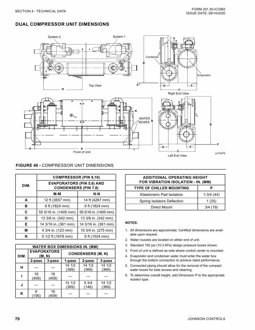
JOHNSON CONTROLS70
FORM 201.30-ICOM2ISSUE DATE: 09/14/2020SECTION 4 - TECHNICAL DATA
NOTES:
1. All dimensions are approximate. Certified dimensions are avail-able upon request.
2. Water nozzles are located on either end of unit.3. Standard 150 psi (10.3 kPa) design pressure boxes shown.3. Front of unit is defined as side where control center is mounted.4. Evaporator and condenser water must enter the water box
through the bottom connection to achieve rated performance.5. Connected piping should allow for the removal of the compact
water boxes for tube access and cleaning. 6. To determine overall height, add Dimension P to the appropriate
isolator type.
DUAL COMPRESSOR UNIT DIMENSIONS
ADDITIONAL OPERATING HEIGHT FOR VIBRATION ISOLATION - IN. (MM)
TYPE OF CHILLER MOUNTING PElastomeric Pad Isolators 1-3/4 (44)
Spring Isolators Deflection 1 (25)Direct Mount 3/4 (19)
DIM.
COMPRESSOR (PIN 9,10) EVAPORATORS (PIN 5,6) AND
CONDENSERS (PIN 7,8)M-M N-N
A 12 ft (3657 mm) 14 ft (4267 mm)B 6 ft (1824 mm) 6 ft (1824 mm)C 55 5/16 in. (1405 mm) 55 5/16 in. (1405 mm)D 13 3/8 in. (342 mm) 13 3/8 in. (342 mm)E 14 3/16 in. (361 mm) 14 3/16 in. (361 mm)M 4 3/4 in. (123 mm) 10 3/4 in. (275 mm)N 5 1/2 ft (1678 mm) 6 ft (1524 mm)
WATER BOX DIMENSIONS IN. (MM)
DIM.EVAPORATORS
(M, N) CONDENSERS (M, N)
2-pass 3-pass 1-pass 2-pass 3-pass
H — — 14 1/2 (369)
14 1/2 (369)
14 1/2 (369)
I 16 (409)
16 (409) — — —
J — — 14 1/2 (369)
5 3/4 (146)
14 1/2 (369)
K 6 (156)
16 (409) — — —
Top View
M
N
System 1System 2
Front of UnitA
K
J
WATER BOXES
H
I
B
Right End View
Condenser
Evaporator
B
P DC
E
DC
E
B
P
Left End View
FIGURE 40 - COMPRESSOR UNIT DIMENSIONS
LD16476
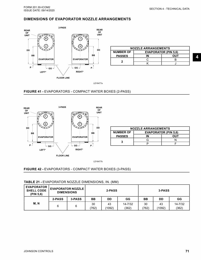
JOHNSON CONTROLS 71
SECTION 4 - TECHNICAL DATAFORM 201.30-ICOM2 ISSUE DATE: 09/14/2020
4
DIMENSIONS OF EVAPORATOR NOZZLE ARRANGEMENTS
NOZZLE ARRANGEMENTSNUMBER OF
PASSESEVAPORATOR (PIN 5,6)IN OUT
2 C BK J
FIGURE 41 - EVAPORATORS - COMPACT WATER BOXES (2-PASS)
NOZZLE ARRANGEMENTSNUMBER OF
PASSESEVAPORATOR (PIN 5,6) IN OUT
3 G NP F
FIGURE 42 - EVAPORATORS - COMPACT WATER BOXES (3-PASS)
TABLE 21 - EVAPORATOR NOZZLE DIMENSIONS, IN. (MM)EVAPORATOR SHELL CODE
(PIN 5,6)
EVAPORATOR NOZZLE DIMENSIONS 2-PASS 3-PASS
M, N2-PASS 3-PASS BB DD GG BB DD GG
6 6 30 (762)
43 (1092)
14-7/32 (362)
30 (762)
43 (1092)
14-7/32 (362)
LD16477a
LD16477b
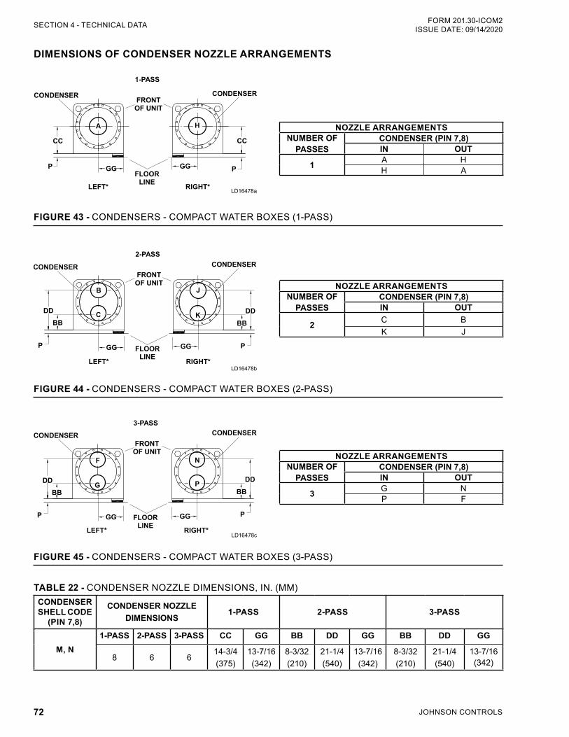
JOHNSON CONTROLS72
FORM 201.30-ICOM2ISSUE DATE: 09/14/2020SECTION 4 - TECHNICAL DATA
DIMENSIONS OF CONDENSER NOZZLE ARRANGEMENTS
NOZZLE ARRANGEMENTSNUMBER OF
PASSESCONDENSER (PIN 7,8)IN OUT
1 A HH A
FIGURE 43 - CONDENSERS - COMPACT WATER BOXES (1-PASS)
TABLE 22 - CONDENSER NOZZLE DIMENSIONS, IN. (MM)CONDENSER SHELL CODE
(PIN 7,8)
CONDENSER NOZZLE DIMENSIONS
1-PASS 2-PASS 3-PASS
M, N1-PASS 2-PASS 3-PASS CC GG BB DD GG BB DD GG
8 6 614-3/4 (375)
13-7/16 (342)
8-3/32 (210)
21-1/4 (540)
13-7/16 (342)
8-3/32 (210)
21-1/4 (540)
13-7/16 (342)
FIGURE 44 - CONDENSERS - COMPACT WATER BOXES (2-PASS)
NOZZLE ARRANGEMENTSNUMBER OF
PASSESCONDENSER (PIN 7,8)IN OUT
2 C BK J
NOZZLE ARRANGEMENTSNUMBER OF
PASSESCONDENSER (PIN 7,8)IN OUT
3 G NP F
FIGURE 45 - CONDENSERS - COMPACT WATER BOXES (3-PASS)
LD16478a
LD16478b
LD16478c
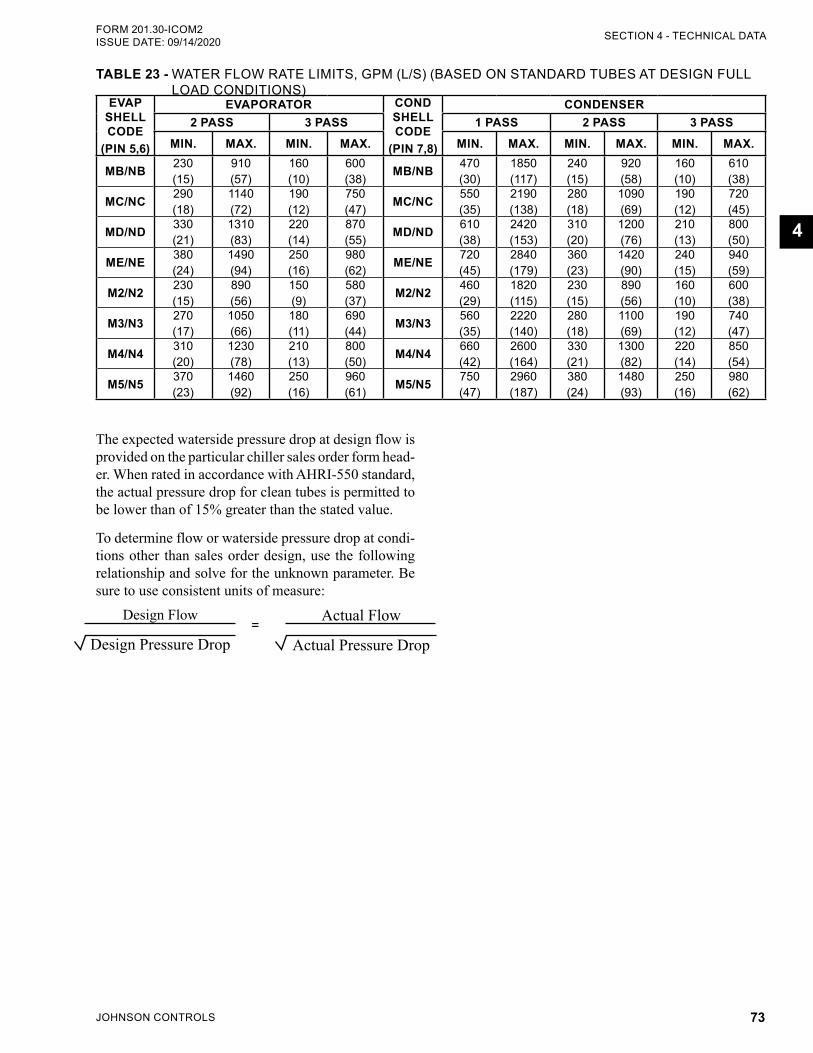
JOHNSON CONTROLS 73
SECTION 4 - TECHNICAL DATAFORM 201.30-ICOM2 ISSUE DATE: 09/14/2020
4
TABLE 23 - WATER FLOW RATE LIMITS, GPM (L/S) (BASED ON STANDARD TUBES AT DESIGN FULL LOAD CONDITIONS)
EVAP SHELL CODE
(PIN 5,6)
EVAPORATOR COND SHELL CODE
(PIN 7,8)
CONDENSER2 PASS 3 PASS 1 PASS 2 PASS 3 PASS
MIN. MAX. MIN. MAX. MIN. MAX. MIN. MAX. MIN. MAX.
MB/NB 230 (15)
910 (57)
160 (10)
600 (38) MB/NB 470
(30)1850 (117)
240 (15)
920 (58)
160 (10)
610 (38)
MC/NC 290 (18)
1140 (72)
190 (12)
750 (47) MC/NC 550
(35)2190 (138)
280 (18)
1090 (69)
190 (12)
720 (45)
MD/ND 330 (21)
1310 (83)
220 (14)
870 (55) MD/ND 610
(38)2420 (153)
310 (20)
1200 (76)
210 (13)
800 (50)
ME/NE 380 (24)
1490 (94)
250 (16)
980 (62) ME/NE 720
(45)2840 (179)
360 (23)
1420 (90)
240 (15)
940 (59)
M2/N2 230 (15)
890 (56)
150 (9)
580 (37) M2/N2 460
(29)1820 (115)
230 (15)
890 (56)
160 (10)
600 (38)
M3/N3 270 (17)
1050 (66)
180 (11)
690 (44) M3/N3 560
(35)2220 (140)
280 (18)
1100 (69)
190 (12)
740 (47)
M4/N4 310 (20)
1230 (78)
210 (13)
800 (50) M4/N4 660
(42)2600 (164)
330 (21)
1300 (82)
220 (14)
850 (54)
M5/N5 370 (23)
1460 (92)
250 (16)
960 (61) M5/N5 750
(47)2960 (187)
380 (24)
1480 (93)
250 (16)
980 (62)
The expected waterside pressure drop at design flow is provided on the particular chiller sales order form head-er. When rated in accordance with AHRI-550 standard, the actual pressure drop for clean tubes is permitted to be lower than of 15% greater than the stated value.
To determine flow or waterside pressure drop at condi-tions other than sales order design, use the following relationship and solve for the unknown parameter. Be sure to use consistent units of measure:
Design Flow
Design Pressure Drop
Actual Flow
Actual Pressure Drop=
JOHNSON CONTROLS74
FORM 201.30-ICOM2ISSUE DATE: 09/14/2020
THIS PAGE INTENTIONALLY LEFT BLANK.
JOHNSON CONTROLS 75
FORM 201.30-ICOM2 ISSUE DATE: 09/14/2020
5
SECTION 5 - COMMISSIONING
PREPARATIONCommissioning of this unit should only be carried out by Johnson Controls au-thorized personnel. Proper electrical lock out/tag out procedures must be followed.
Make sure all checks are completed in the Start-up Checklist (Form 201.30-CL2) on the next page. The chiller is then ready to be placed into operation.
Commissioning personnel should be thoroughly fa-miliar with the information contained in this document before starting the unit.
For helpful tips about commissioning the unit, see the following information.
Refrigerant ChargePackaged units are normally shipped as standard with a full refrigerant operating charge. See the following instructions to make sure the refrigerant is handled correctly.
• Do not evacuate or liquid charge with static water in the cooler or condenser.
• Turn the pumps on.
• Vapor charge until the system pressure is above the saturated temperature for freezing of the fluid in the
• Liquid charge slowly to avoid excessive thermal stress at the charging point, and to make sure the refrigerant temperature does not go below the freezing point with liquid refrigerant in the evap-orator and condenser.
• Evacuation and charging should always be done according to SECTION 7 - MAINTENANCE.
Service and Oil Line ValvesIf valves are of the back-seat type, open them fully (counterclockwise), then close one turn of the stem.
Compressor OilWhile the compressor is running at design speed, the oil level should be visible between the bottom of the lower and middle of the upper sight glass of the oil separator.
Make sure that the compressor heaters have been energized at least 24 hours before starting the chiller.
FIRST TIME START-UPDuring the commissioning period, there should be sufficient heat load to run the unit under stable full load operation to enable the unit controls, and system op-eration to be set up correctly, and a com-missioning log taken.
When a compressor is running, the controller monitors oil pressure, motor current, and various other system parameters, such as discharge pressure, chilled liquid temperature, etc. Should any problems occur; the con-trol system will immediately take appropriate action and display the nature of the fault.
LoadingOnce the unit has been started, all operations are fully automatic. After an initial period at minimum capacity, the control system will adjust the unit load depending on the chilled liquid temperature and rate of tempera-ture change. If a high heat load is present, the control-ler will increase the speed of the compressors.
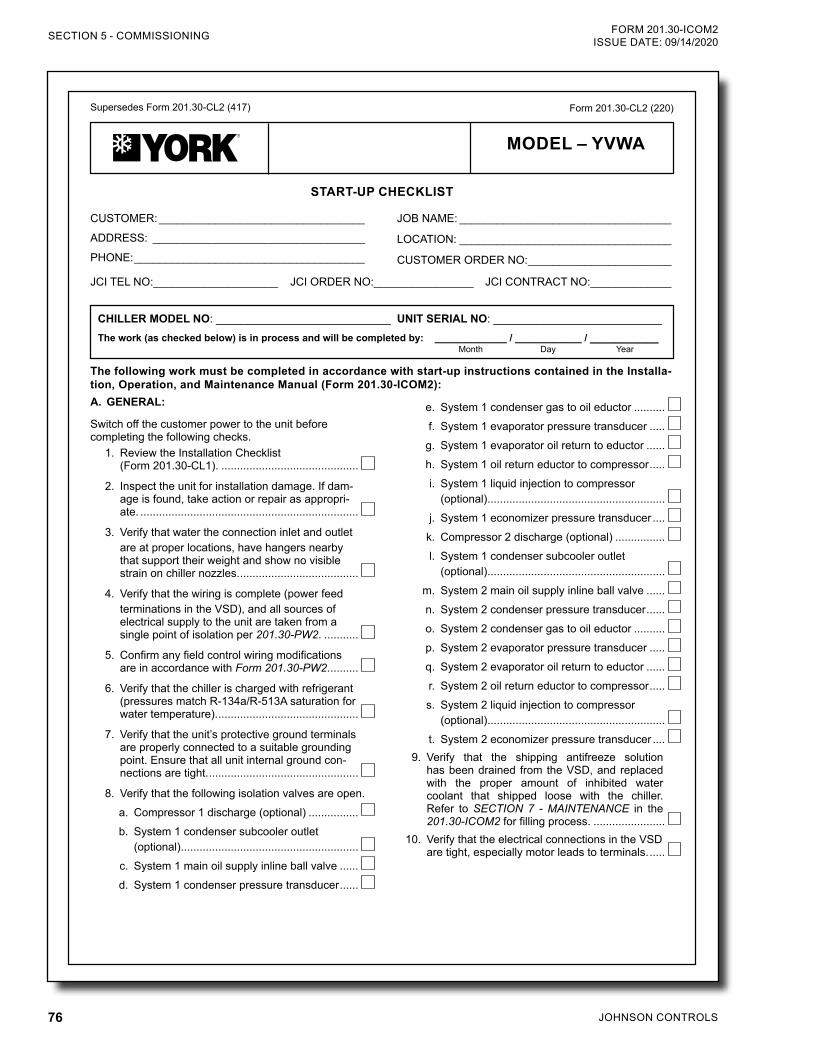
JOHNSON CONTROLS76
FORM 201.30-ICOM2ISSUE DATE: 09/14/2020SECTION 5 - COMMISSIONING
JOHNSON CONTROLS 1
Supersedes Form 201.30-CL2 (417)
START-UP CHECKLIST
Form 201.30-CL2 (220)
The following work must be completed in accordance with start-up instructions contained in the Installa-tion, Operation, and Maintenance Manual (Form 201.30-ICOM2):
CUSTOMER: _________________________________
ADDRESS: __________________________________
PHONE: _____________________________________
JCI TEL NO:____________________ JCI ORDER NO:________________ JCI CONTRACT NO:_____________
JOB NAME: __________________________________
LOCATION: __________________________________
CUSTOMER ORDER NO: _______________________
CHILLER MODEL NO: ____________________________The work (as checked below) is in process and will be completed by: _____________ / ____________ / ___________
UNIT SERIAL NO: ___________________________
Month Day Year
e. System 1 condenser gas to oil eductor ..........f. System 1 evaporator pressure transducer .....
g. System 1 evaporator oil return to eductor ......h. System 1 oil return eductor to compressor .....i. System 1 liquid injection to compressor
(optional) .........................................................j. System 1 economizer pressure transducer ....k. Compressor 2 discharge (optional) ................l. System 1 condenser subcooler outlet
(optional) .........................................................m. System 2 main oil supply inline ball valve ......n. System 2 condenser pressure transducer ......o. System 2 condenser gas to oil eductor ..........p. System 2 evaporator pressure transducer .....q. System 2 evaporator oil return to eductor ......r. System 2 oil return eductor to compressor .....s. System 2 liquid injection to compressor
(optional) .........................................................t. System 2 economizer pressure transducer ....
9. Verify that the shipping antifreeze solution has been drained from the VSD, and replaced with the proper amount of inhibited water coolant that shipped loose with the chiller. Refer to SECTION 7 - MAINTENANCE in the 201.30-ICOM2 for filling process. .......................
10. Verify that the electrical connections in the VSD are tight, especially motor leads to terminals. .....
A. GENERAL:
Switch off the customer power to the unit before completing the following checks.
1. Review the Installation Checklist (Form 201.30-CL1). ............................................
2. Inspect the unit for installation damage. If dam-age is found, take action or repair as appropri-ate. ......................................................................
3. Verify that water the connection inlet and outlet are at proper locations, have hangers nearby that support their weight and show no visible strain on chiller nozzles. ......................................
4. Verify that the wiring is complete (power feed terminations in the VSD), and all sources of electrical supply to the unit are taken from a single point of isolation per 201.30-PW2. ...........
5. Confirm any field control wiring modifications are in accordance with Form 201.30-PW2. .........
6. Verify that the chiller is charged with refrigerant (pressures match R-134a/R-513A saturation for water temperature). .............................................
7. Verify that the unit’s protective ground terminals are properly connected to a suitable grounding point. Ensure that all unit internal ground con-nections are tight. ................................................
8. Verify that the following isolation valves are open.a. Compressor 1 discharge (optional) ................b. System 1 condenser subcooler outlet
(optional) .........................................................c. System 1 main oil supply inline ball valve ......d. System 1 condenser pressure transducer ......
MODEL – YVWA
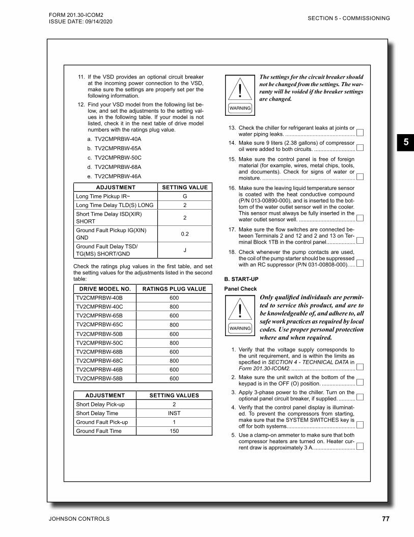
JOHNSON CONTROLS 77
SECTION 5 - COMMISSIONINGFORM 201.30-ICOM2 ISSUE DATE: 09/14/2020
5
JOHNSON CONTROLS2
FORM 201.30-CL2 ISSUE DATE: 02/14/2020
11. If the VSD provides an optional circuit breaker at the incoming power connection to the VSD, make sure the settings are properly set per the following information.
12. Find your VSD model from the following list be-low, and set the adjustments to the setting val-ues in the following table. If your model is not listed, check it in the next table of drive model numbers with the ratings plug value.a. TV2CMPRBW-40Ab. TV2CMPRBW-65Ac. TV2CMPRBW-50Cd. TV2CMPRBW-68Ae. TV2CMPRBW-46A
ADJUSTMENT SETTING VALUELong Time Pickup IR~ GLong Time Delay TLD(S) LONG 2Short Time Delay ISD(XIR) SHORT 2
Ground Fault Pickup IG(XIN) GND 0.2
Ground Fault Delay TSD/TG(MS) SHORT/GND J
Check the ratings plug values in the first table, and set the setting values for the adjustments listed in the second table:
DRIVE MODEL NO. RATINGS PLUG VALUETV2CMPRBW-40B 600TV2CMPRBW-40C 800TV2CMPRBW-65B 600TV2CMPRBW-65C 800TV2CMPRBW-50B 600TV2CMPRBW-50C 800TV2CMPRBW-68B 600TV2CMPRBW-68C 800TV2CMPRBW-46B 600TV2CMPRBW-58B 600
ADJUSTMENT SETTING VALUESShort Delay Pick-up 2Short Delay Time INSTGround Fault Pick-up 1Ground Fault Time 150
The settings for the circuit breaker should not be changed from the settings. The war-ranty will be voided if the breaker settings are changed.
13. Check the chiller for refrigerant leaks at joints or water piping leaks. ..............................................
14. Make sure 9 liters (2.38 gallons) of compressor oil were added to both circuits. ...........................
15. Make sure the control panel is free of foreign material (for example, wires, metal chips, tools, and documents). Check for signs of water or moisture. .............................................................
16. Make sure the leaving liquid temperature sensor is coated with the heat conductive compound (P/N 013-00890-000), and is inserted to the bot-tom of the water outlet sensor well in the cooler. This sensor must always be fully inserted in the water outlet sensor well. .....................................
17. Make sure the flow switches are connected be-tween Terminals 2 and 12 and 2 and 13 on Ter-minal Block 1TB in the control panel. ..................
18. Check whenever the pump contacts are used, the coil of the pump starter should be suppressed with an RC suppressor (P/N 031-00808-000). ....
B. START-UPPanel Check
Only qualified individuals are permit-ted to service this product, and are to be knowledgeable of, and adhere to, all safe work practices as required by local codes. Use proper personal protection where and when required.
1. Verify that the voltage supply corresponds to the unit requirement, and is within the limits as specified in SECTION 4 - TECHNICAL DATA in Form 201.30-ICOM2. ..........................................
2. Make sure the unit switch at the bottom of the keypad is in the OFF (O) position. ......................
3. Apply 3-phase power to the chiller. Turn on the optional panel circuit breaker, if supplied. ...........
4. Verify that the control panel display is illuminat-ed. To prevent the compressors from starting, make sure that the SYSTEM SWITCHES key is off for both systems. ............................................
5. Use a clamp-on ammeter to make sure that both compressor heaters are turned on. Heater cur-rent draw is approximately 3 A. ...........................
JOHNSON CONTROLS78
FORM 201.30-ICOM2ISSUE DATE: 09/14/2020SECTION 5 - COMMISSIONING
JOHNSON CONTROLS 3
FORM 201.30-CL2 ISSUE DATE: 02/14/2020
Programmed Operating ValuesProgram the required operating values into the micropro-cessor. Then record them below. Refer to the PROGRAM key in SECTION 6 - OPERATION in 201.30-ICOM2 for low and high limits, and default values.
1. Chilled Liquid Leaving Temperature Cutout =__________________°F (°C)
2. Motor Current Limit = __________________% FLA
3. Pulldown Motor Current Limit = __________% FLA
4. Pulldown Motor Current Limit Time = _______MIN
5. Motor Temp Unload = _________________°F (°C)
6. Unit ID Number = __________________________
7. Sys 1 Condenser Liquid Ref Level = ____________
8. Sys 2 Condenser Liquid Ref Level = ____________
Liquid Control SetpointProgram the chilled and condenser liquid (optional heat pump) setpoints and ranges, then record them below:
1. Leaving Chilled Liquid Temp Setpoint = ______________________°F (°C)
2. Leaving Chilled Liquid Temp Control Range = _________________°F (°C)
3. Maximum Leaving Chilled Liquid Remote Temp Reset = _________________°F (°C)
4. Leaving Condenser Liquid Temp Setpoint = ______________________°F (°C)
5. Leaving Condenser Liquid Temp Control Range = _________________°F (°C)
6. Maximum Leaving Condenser Liquid Remote Temp Reset = _________________°F (°C)
Date/Time and Daily Schedule
1. Make sure that the CLK Jumper JP2 on the con-trol board is in the ON position. Press the DATE/TIME key to set the date and time. .....................
2. To program the daily and holiday start/stop, press the SCHEDULE key. .................................
6. Confirm that the compressor overload current settings have been correctly adjusted by the fac-tory. These are not normally required to be re-set. Use the VSD DATA key on the control panel, navigate to the COMP1 MOTOR OVERLOAD = ### AMPS and COMP2 MOTOR OVERLOAD = ### AMPS screens. The values should match the values on the overload setting label, which is located inside of the VSD cabinet. If the values do not match, an adjustment is required inside the VSD cabinet by qualified service personnel. .
7. Record the overload settings below:System 1: __________________________ A
System 2: __________________________ A
Setting the potentiometers incorrectly may cause damage to the equipment.
8. Press the STATUS key. If the following UNIT WARNING message appears, immediately contact Johnson Controls Product Technical Support to request the password to reprogram the serial number, and any other important fac-tory programmed information that was lost. ........UNIT WARNING: INVALID SERIAL NUMBER ENTER UNIT SERIAL NUMBER
Programmed OptionsProgram the required options in the control panel for the required operating requirements, then record the values below. Refer to the PROGRAM key in SECTION 6 - OP-ERATION in Form 201.30-ICOM2 for more information:
1. Display Language = ________________________
2. Chilled Liquid Mode = _______________________
3. Local/Remote Mode = _______________________
4. Display Units = ____________________________
5. Lead/Lag Control = _________________________
6. Remote Temp Reset = ______________________
7. Remote Current Reset =_____________________
8. Compressor Selection = _____________________
9. Operating Mode (Heat Pump) = _______________
JOHNSON CONTROLS 79
SECTION 5 - COMMISSIONINGFORM 201.30-ICOM2 ISSUE DATE: 09/14/2020
5
FORM 201.30-CL2 ISSUE DATE: 02/14/2020
5000 Renaissance Drive, New Freedom, Pennsylvania USA 17349 1-800-524-1330 Subject to change without notice. Printed in USACopyright © by Johnson Controls 2020 www.johnsoncontrols.com ALL RIGHTS RESERVEDForm 201.30-CL2 (220)Issue Date: February 14, 2020 Supersedes: 201.30-CL2 (417)
C. CHILLER SYSTEMAfter completion of the following checks for System 1, switch off the Sys-tem 1 switch on the keypad and repeat the process for System 2. When both systems are running correctly, stop the unit, switch all applicable switches ON, and restart the unit.
1. Ensure power is on the chiller to energize the compressor heaters 24 hours before start-up. ....
2. Ensure the SYSTEM SWITCHES key is OFF for both systems. ......................................................
3. Turn the unit switch to the ON position. ..............
4. If the chilled and condenser liquid pumps are manually operated, start the pumps. The con-trol center does not allow the chiller to start un-less flow is established through the unit. If the pumps are wired to the control center, over-ride the contact to start the pumps to verify the flow. .....................................................................
5. Throttle back flow to make sure the flow switch opens with a loss of flow. If the pump is turned off during chiller operation, place the auxiliary pump contacts in series with the flow switch for additional protection. ...........................................
6. Evaluate cooler and condenser water flow indi-cation compared to design information on the sales order. If shell pressure drop is used, it should be within +/- 15% of the rating informa-tion. .....................................................................
7. If the chilled water and condenser pump run contacts on the chiller were overridden to check flow, remove overrides. Pumps get start com-mand when chiller initiates run. ...........................
8. Press the SYSTEM SWITCHES key, and turn on System 1 or 2 SWITCH. There may be a few seconds delay before the compressor starts be-cause of the anti-recycle timer. Be ready, when each compressor starts, to switch the UNIT switch to the OFF position immediately, if any unusual noises or other adverse conditions de-velop. ..................................................................
9. When the compressor starts, press the relevant System Pressures key to verify that oil differen-tial pressure develops immediately. If oil pres-sure does not develop, the automatic controls shut down the compressor. Do not attempt to re-start the compressor, which does not develop oil pressure immediately. Switch the UNIT switch to the OFF position. ................................................
10. As the chiller is started, verify that the refrigerant level sensor tracks level from empty condens-er to fully flooded level sensor probe over the range of less than 10% to almost 100%. ............
11. Adjust condenser refrigerant liquid level setpoint to a value that covers the subcooler top and pro-vides proper evaporator performance with the chiller running steady. .........................................
12. After the chiller is at full load at Design Leaving Chilled Liquid Temperature, capture the operat-ing data to print or save to text file. .....................

JOHNSON CONTROLS80
FORM 201.30-ICOM2ISSUE DATE: 09/14/2020
THIS PAGE INTENTIONALLY LEFT BLANK.
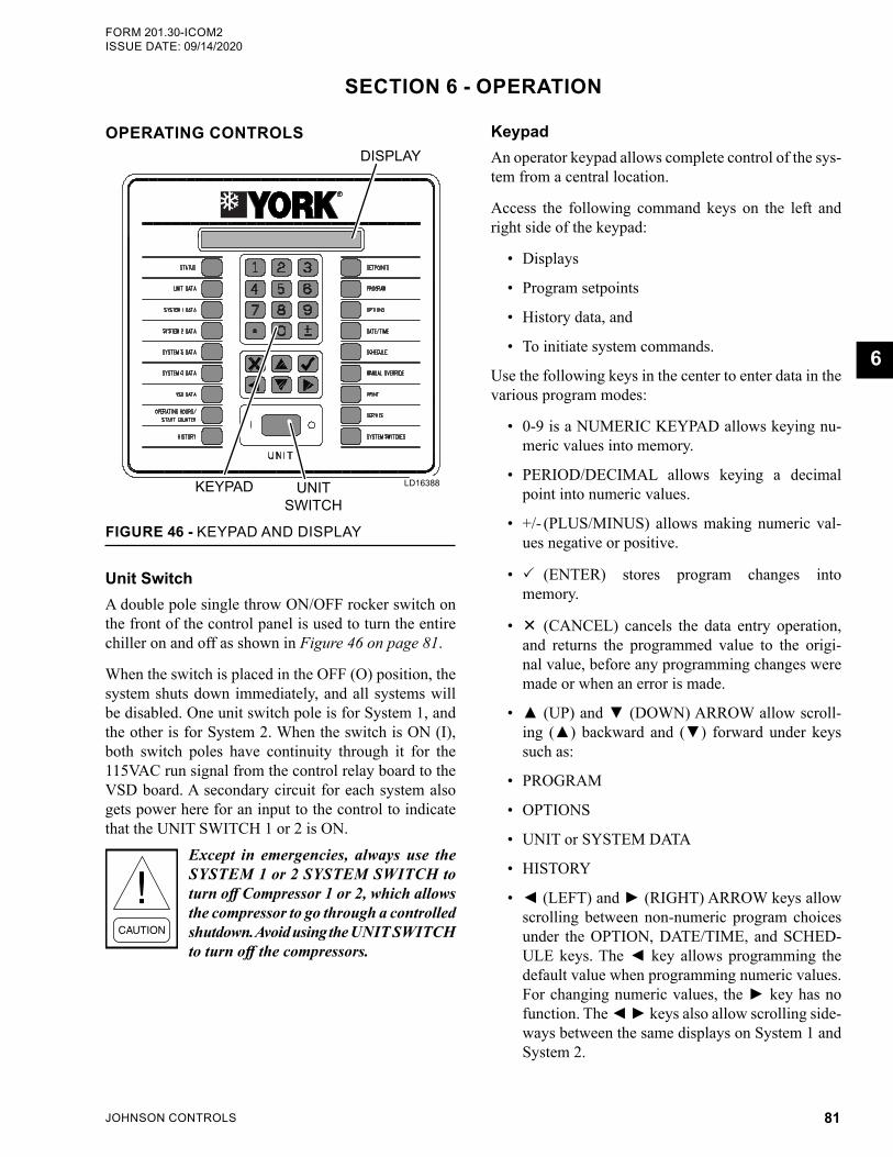
JOHNSON CONTROLS 81
FORM 201.30-ICOM2 ISSUE DATE: 09/14/2020
6
OPERATING CONTROLS
LD19539UNITSWITCH
KEYPAD
DISPLAY
FIGURE 46 - KEYPAD AND DISPLAY
LD16388
Unit SwitchA double pole single throw ON/OFF rocker switch on the front of the control panel is used to turn the entire chiller on and off as shown in Figure 46 on page 81.
When the switch is placed in the OFF (O) position, the system shuts down immediately, and all systems will be disabled. One unit switch pole is for System 1, and the other is for System 2. When the switch is ON (I), both switch poles have continuity through it for the 115VAC run signal from the control relay board to the VSD board. A secondary circuit for each system also gets power here for an input to the control to indicate that the UNIT SWITCH 1 or 2 is ON.
Except in emergencies, always use the SYSTEM 1 or 2 SYSTEM SWITCH to turn off Compressor 1 or 2, which allows the compressor to go through a controlled shutdown. Avoid using the UNIT SWITCH to turn off the compressors.
KeypadAn operator keypad allows complete control of the sys-tem from a central location.
Access the following command keys on the left and right side of the keypad:
• Displays
• Program setpoints
• History data, and
• To initiate system commands.
Use the following keys in the center to enter data in the various program modes:
• 0-9 is a NUMERIC KEYPAD allows keying nu-meric values into memory.
• PERIOD/DECIMAL allows keying a decimal point into numeric values.
• +/- (PLUS/MINUS) allows making numeric val-ues negative or positive.
• (ENTER) stores program changes into memory.
• (CANCEL) cancels the data entry operation, and returns the programmed value to the origi-nal value, before any programming changes were made or when an error is made.
• (UP) and (DOWN) ARROW allow scroll-ing () backward and () forward under keys such as:
• PROGRAM
• OPTIONS
• UNIT or SYSTEM DATA
• HISTORY
• (LEFT) and (RIGHT) ARROW keys allow scrolling between non-numeric program choices under the OPTION, DATE/TIME, and SCHED-ULE keys. The key allows programming the default value when programming numeric values. For changing numeric values, the key has no function. The keys also allow scrolling side-ways between the same displays on System 1 and System 2.
SECTION 6 - OPERATION
JOHNSON CONTROLS82
FORM 201.30-ICOM2ISSUE DATE: 09/14/2020SECTION 6 - OPERATION
Press the key to move the display to System 2. Pressing the key moves the display in the opposite direction. The arrow keys also allow fast scrolling through subgroups of data under keys, such as HISTORY.
Use the ,,, and keys to see the multiple dis-plays under a key. Once the keys are pressed and used for scrolling, pressing the original data key will return to the first display message displayed under the data keys.
The keypad uses an overlay to convert the keypad to various languages.
Keypad Data Entry Mode
Enter Data Entry ModeFor numeric programmable items, enter DATA EN-TRY by pressing any numbered key, the decimal point, or the +/- key. The data will be entered, and the cursor will appear under the position where the data is being entered.
For non-numeric programmable items, enter DATA ENTRY by pressing the or key. The cursor will appear under the first position of the non-numeric string. Press the or key to change the program-mable choice.
Exit Data Entry Mode
To exit DATA ENTRY, press the key or X, then the cursor will disappear. If the user presses any other key while in DATA ENTRY, the user has two seconds to accept or cancel the change.
XXXXXXXXXXX PRESS TO ACCEPT VALUE OR X TO CANCEL DATA ENTRY
If the key was pressed while in DATA ENTRY, and the numeric value entered was out of range, the following message will appear for two seconds followed by the original data display.
XXXXXXXXXXX OUT OF RANGE TRY AGAIN!XXXXXXXXXXXXXXXXXXXXXXXXXXXXXXXXXXXX
DisplayThe 80-character (two lines of 40 characters) display is a Liquid Crystal Display (LCD) used for displaying unit, system parameters, and operator messages. The display has an LED backlight for night viewing, and is viewable in direct sunlight.
BASIC OPERATING SEQUENCE
Start Sequence and LoadingTo start the chiller, the following conditions must be satisfied before the VSD DC BUS PRECHARGE will take place:
• Unit switch must be ON.
• At least one system switch is ON.
• Run permissive and flow switch inputs have closed switches to Terminal 2.
• No unit faults or start inhibits exist.
• At least one system is not faulted or inhibited.
• Daily schedule calls for the chiller to run.
• Leaving chilled liquid setpoint is above the setpoint high limit (setpoint plus cooling range).
Once the anti-recycle timer times out, the chiller con-trol system will select the number of compressors to start, precharge the VSD, and begin operating the com-pressors. The compressors speed will be ramped to the minimum start frequency and will increase speed as needed in an effort to regulate the Leaving Chilled Liquid Temperature to meet the required setpoint. In optional HEAT PUMP MODE, the Leaving Condenser Liquid Temperature is regulated to setpoint. In auto-matic LEAD/LAG control, the logic leads with the compressor with the lowest run time.
Anti-Recycle TimerThe anti-recycle timer will be set for 120 seconds when:
• The control panel is powered up. The timer must time out before a compressor is allowed to start.
• A system starts. The timer will count down from the time the motor starts, and it must time out be-fore another compressor is allowed to start.
• A system shuts down. The timer must time out be-fore the system is allowed to restart.
Evaporator and Condenser Pump ControlThe evaporator and condenser pump dry contacts are energized when any of the following conditions are true:
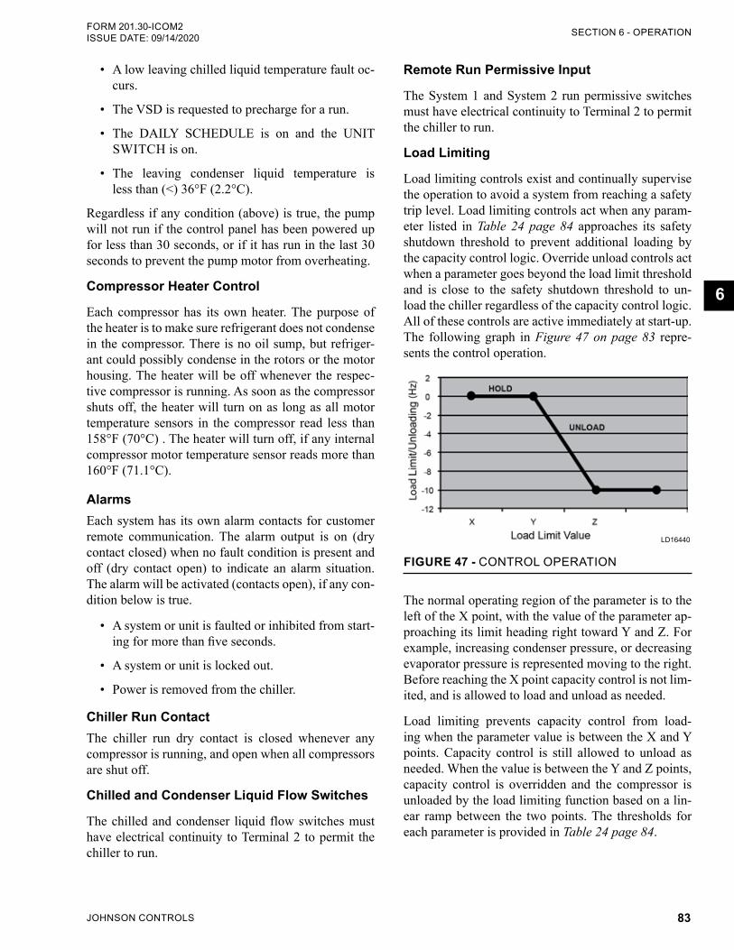
JOHNSON CONTROLS 83
SECTION 6 - OPERATIONFORM 201.30-ICOM2 ISSUE DATE: 09/14/2020
6
• A low leaving chilled liquid temperature fault oc-curs.
• The VSD is requested to precharge for a run.
• The DAILY SCHEDULE is on and the UNIT SWITCH is on.
• The leaving condenser liquid temperature is less than (<) 36°F (2.2°C).
Regardless if any condition (above) is true, the pump will not run if the control panel has been powered up for less than 30 seconds, or if it has run in the last 30 seconds to prevent the pump motor from overheating.
Compressor Heater Control
Each compressor has its own heater. The purpose of the heater is to make sure refrigerant does not condense in the compressor. There is no oil sump, but refriger-ant could possibly condense in the rotors or the motor housing. The heater will be off whenever the respec-tive compressor is running. As soon as the compressor shuts off, the heater will turn on as long as all motor temperature sensors in the compressor read less than 158°F (70°C) . The heater will turn off, if any internal compressor motor temperature sensor reads more than 160°F (71.1°C).
AlarmsEach system has its own alarm contacts for customer remote communication. The alarm output is on (dry contact closed) when no fault condition is present and off (dry contact open) to indicate an alarm situation. The alarm will be activated (contacts open), if any con-dition below is true.
• A system or unit is faulted or inhibited from start-ing for more than five seconds.
• A system or unit is locked out.
• Power is removed from the chiller.
Chiller Run ContactThe chiller run dry contact is closed whenever any compressor is running, and open when all compressors are shut off.
Chilled and Condenser Liquid Flow Switches
The chilled and condenser liquid flow switches must have electrical continuity to Terminal 2 to permit the chiller to run.
Remote Run Permissive Input
The System 1 and System 2 run permissive switches must have electrical continuity to Terminal 2 to permit the chiller to run.
Load Limiting
Load limiting controls exist and continually supervise the operation to avoid a system from reaching a safety trip level. Load limiting controls act when any param-eter listed in Table 24 page 84 approaches its safety shutdown threshold to prevent additional loading by the capacity control logic. Override unload controls act when a parameter goes beyond the load limit threshold and is close to the safety shutdown threshold to un-load the chiller regardless of the capacity control logic. All of these controls are active immediately at start-up. The following graph in Figure 47 on page 83 repre-sents the control operation.
FIGURE 47 - CONTROL OPERATION
LD16440
The normal operating region of the parameter is to the left of the X point, with the value of the parameter ap-proaching its limit heading right toward Y and Z. For example, increasing condenser pressure, or decreasing evaporator pressure is represented moving to the right. Before reaching the X point capacity control is not lim-ited, and is allowed to load and unload as needed.
Load limiting prevents capacity control from load-ing when the parameter value is between the X and Y points. Capacity control is still allowed to unload as needed. When the value is between the Y and Z points, capacity control is overridden and the compressor is unloaded by the load limiting function based on a lin-ear ramp between the two points. The thresholds for each parameter is provided in Table 24 page 84.
JOHNSON CONTROLS84
FORM 201.30-ICOM2ISSUE DATE: 09/14/2020SECTION 6 - OPERATION
TABLE 24 - LOAD LIMITING VALUESPARAMETER
(X AXIS UNITS) X POINT Y POINT Z POINT
MOTOR CURRENT (%FLA) Active Current Limit Setting – 2% FLA Active Current Limit Setting Active Current Limit Setting +
5% FLA
DISCHARGE PRESSURE High Discharge Pressure Cutout – 15 psig
High Discharge Pressure Cutout – 15 psig
High Discharge Pressure Cutout
EVAPORATOR PRESSURE Low Evaporator Pressure Cutout + 10 psig
Low Evaporator Pressure Cutout + 5 psig
Low Evaporator Pressure Cutout
VSD INTERNAL AMBIENT TEMP
VSD Internal Ambient Cutout – 3°F
VSD Internal Ambient Cutout – 2°F VSD Internal Ambient Cutout
VSD BASEPLATE TEMP VSD Baseplate Temp – 8°F VSD Baseplate Temp – 4°F VSD Baseplate TempLEAVING CHILLED LIQUID
TEMPERATURE (HEAT PUMP MODE ONLY)
Low Leaving Chilled Liquid Temp Cutout – + 8°F
Low Leaving Chilled Liquid Temp Cutout – +4°F
Low Leaving Chilled Liquid Temp Cutout – +1°F
NOTE: All of the controls above are active immediately at start-up.
• Remote BAS Comms Reset: Set the LCHLT setpoint via the BAS COMMS. The control panel will only accept a remote setpoint from the BAS, if the control panel is in REMOTE CONTROL mode (under OPTIONS). If the control panel is in LOCAL CONTROL mode, the BAS setpoint will be ignored, and the remote LCHLT setpoint is set to the local setpoint. The minimum and maxi-mum allowable reset values will be the same as those allowable programmable values for the lo-cal setpoint. If these values are exceeded by the BAS, the minimum or maximum value will be used.
• Remote Analog Reset: Set the remote LCHLT setpoint via the REMOTE TEMPERATURE RESET analog input. A zero signal input (0%) equates to a 0°F (0°C) offset to the local setpoint. A full scale signal input (100%) equates to a posi-tive offset to the local setpoint equal to the pro-grammable maximum REMOTE TEMP RESET. The offset is linear and may be adjusted between 0% and 100% points. The maximum setpoint allowed is the maximum programmable local setpoint, which will be capped at this value, if the calculated setpoint with temperature offset ex-ceeds this value.
This input may be used either in LOCAL or RE-MOTE CONTROL mode, which will only oper-ate if enabled under the UNIT SETUP mode and the OPTIONS key. The input will be ignored if the REMOTE TEMP RESET is disabled un-der the OPTIONS key, or if there are valid BAS COMMS while in REMOTE CONTROL mode. Once a change to the input is registered, a timer is set to the value of the REMOTE INPUTS SER-
Pulldown Current Limit SetpointSet this setpoint under the PROGRAM key, which is only active on start-up for the time defined by the PULLDOWN CURRENT LIMIT TIME. After the run time has exceeded this time, the PULLDOWN CUR-RENT LIMIT setpoint is ignored.
This control is useful in limiting current pulldown de-mand during peak usage periods where electric costs are highest.
Limiting current may interfere with capacity control, pulling down chilled liquid temperatures on hot water starts, and maintaining chilled liquid setpoints.
If there are questions about the following reset con-trols, contact a Johnson Controls BAS representative for details on BAS controls and capabilities.
Leaving Chilled Liquid Temperature (LCHLT) Reset Control The LCHLT RESET CONTROL is used to reset the actual LCHLT setpoint used in capacity control. See the three methods below to reset the LCHLT setpoint:
• Local Cooling Reset: Reprogram the local cool-ing setpoint under the SETPOINTS key, which is the value to which the unit will control the LCHLT, if no other method is active.
REMOTE TEMPERATURE LIMIT RESET is only possible if the option is enabled by select-ing OPTIONS key, and programmable password protected UNIT SETUP MODE from the factory.
JOHNSON CONTROLS 85
SECTION 6 - OPERATIONFORM 201.30-ICOM2 ISSUE DATE: 09/14/2020
6
VICE TIME as programmable under the UNIT SETUP mode at the factory for the 15 minutes (default). The low limit is five minutes and the high limit is 60 minutes. The remote input will be ignored until this timer expires. The timer en-sures that rapid changes in a remote reset signal don’t result in poor temperature control or exces-sive compressor cycling. In most instances, this timer will not need to be changed, since resetting it more often than every 15 minutes will create problems with chilled liquid temperature con-trol. A Johnson Controls Factory Service Center should be contacted if a timer change is required.
Optional Heat Pump Mode SelectionIf the chiller was purchased with the heat pump option, there are two ways to toggle operation between the con-trolling leaving chilled liquid temperature to setpoint in chiller mode, or controlling leaving condenser liquid temperature to setpoint in heat pump mode.
Local Heat Pump Mode: Use the OPTIONS key to set the operating mode to CHILLER or HEAT PUMP.
Remote Heat Pump Mode: In the REMOTE MODE only, select Chiller Mode (OPEN CONTACTS) or Heat Pump Mode (CLOSED CONTACTS) using ex-ternal contacts across control panel Terminals 40 and 41 in Terminal Block 1TB.
Optional Heat Pump Leaving Condenser Liquid Temperature (LCLT) Reset ControlLCLT Reset Control is used to reset the actual LCLT setpoint used in capacity control. See the three meth-ods below to reset the LCLT setpoint:
• Local Condenser Reset: Reprogram the lo-cal cooling setpoint under the SETPOINTS key, which is the value to which the unit will control the LCLT, if no other method is active.
REMOTE TEMPERATURE LIMIT RESET is only possible if the option is enabled by select-ing OPTIONS key, and programmable password protected UNIT SETUP MODE from the factory.
• Remote BAS Comms Reset: Set the LCLT setpoint via the BAS COMMS. The control panel will only accept a remote setpoint from the BAS, if the control panel is in REMOTE CONTROL MODE (under the OPTIONS key). If the control panel is in LOCAL CONTROL MODE, the BAS setpoint will be ignored, and the LCLT setpoint is set to the local setpoint.
The minimum and maximum allowable reset val-ues will be the same as those allowable program-mable values for the local setpoint. If these values are exceeded by the BAS, the minimum or maxi-mum value will be used.
• Remote Analog Reset: Set the remote LCLT via the REMOTE TEMPERATURE RESET ana-log input. A zero signal input (0%) equates to a 0°F (0°C) offset to the local setpoint. A full scale signal input (100%) equates to a negative offset to the local setpoint equal to the programmable minimum REMOTE TEMP RESET. The offset is linear and may be adjusted between 0% and 100% points. The minimum setpoint allowed is the min-imum programmable local setpoint, which will be capped at this value, if the calculated setpoint with temperature offset exceeds this value.
Current Limit Reset ControlCURRENT LIMIT RESET is used to reset the actual CURRENT LIMIT setpoint used in current limit con-trol. See the three methods below to reset the current limit setpoint:
• Local Current Limit Reset: Reprogram the LO-CAL CURRENT LIMIT setpoint under the PRO-GRAM key. This is the value to which the unit will control the current limit and override capacity control, if none of the other methods is active.
REMOTE CURRENT LIMIT RESET is only possible, if the option is enabled by selecting both the OPTIONS key, while in the factory program-mable password protected UNIT SETUP MODE.
• Remote BAS Current Limit Reset: Set the BAS CURRENT LIMIT via the BAS COMMS. The control panel will only accept a CURRENT LIMIT setpoint from the BAS if the control panel is in REMOTE CONTROL MODE (OPTIONS key). If the control panel is in LOCAL CON-TROL MODE, the BAS setpoint will be ignored. The minimum and maximum allowable values will be the same as the minimum and maximum allowable reset values for the CURRENT LIM-IT setpoint under the PROGRAM key. If these values are exceeded, the minimum or maximum value will be used.
JOHNSON CONTROLS86
FORM 201.30-ICOM2ISSUE DATE: 09/14/2020SECTION 6 - OPERATION
• Remote Current Limit Analog Reset: Set the CURRENT LIMIT setpoint via the REMOTE CURRENT LIMIT analog input. A zero signal input (0% ) equates to the maximum current limit setpoint as defined under the PROGRAM key CURRENT LIMIT setpoint. A full scale sig-nal input (100% input) equates to the minimum current limit setpoint as defined under the PRO-GRAM key CURRENT LIMIT setpoint. The current limit value is linear and may be adjusted anywhere between the maximum and minimum points of 0% (no offset) and 100% (max. current limiting).
This input may be used in LOCAL or REMOTE CONTROL MODE. This input will be ignored if the REMOTE CURRENT LIMIT is disabled under the OPTIONS key. Once a change to the input is registered, a timer is set to the value of the REMOTE INPUTS SERVICE TIME as programmable under the UNIT SETUP MODE at the factory for the default value of 15 minutes. The low limit is five minutes, and the high limit is 60 minutes.
The remote input will be ignored until this timer expires. The timer ensures that rapid changes in a remote reset signal don’t result in poor tem-perature control or excessive compressor cycling. In most instances, this timer will not need to be changed, since reset more often than 15 minutes will create problems with chilled liquid tempera-ture control. Contact a Johnson Controls Factory Service Center if a timer change is required.
USER INTERFACEThe keys, detailed in the following pages, provide vari-ous displays of unit related data. Press the or key repeatedly to select multiple display messages. The display messages that contain a number symbol (#) will be replaced with the chiller's present value, which are listed below:
• SYS X = 1 or 2
• ###.# °F = Temperature Data
• ####.# % = Percent (0 to 100%)
• ### = :
• Time Data, i.e. seconds (SEC)
• PSIG/PSID = Pressure Gauge/ Pressure Difference
• Hz = Hertz
• AMPS = Amperage
• FLA = Full Load Amperage
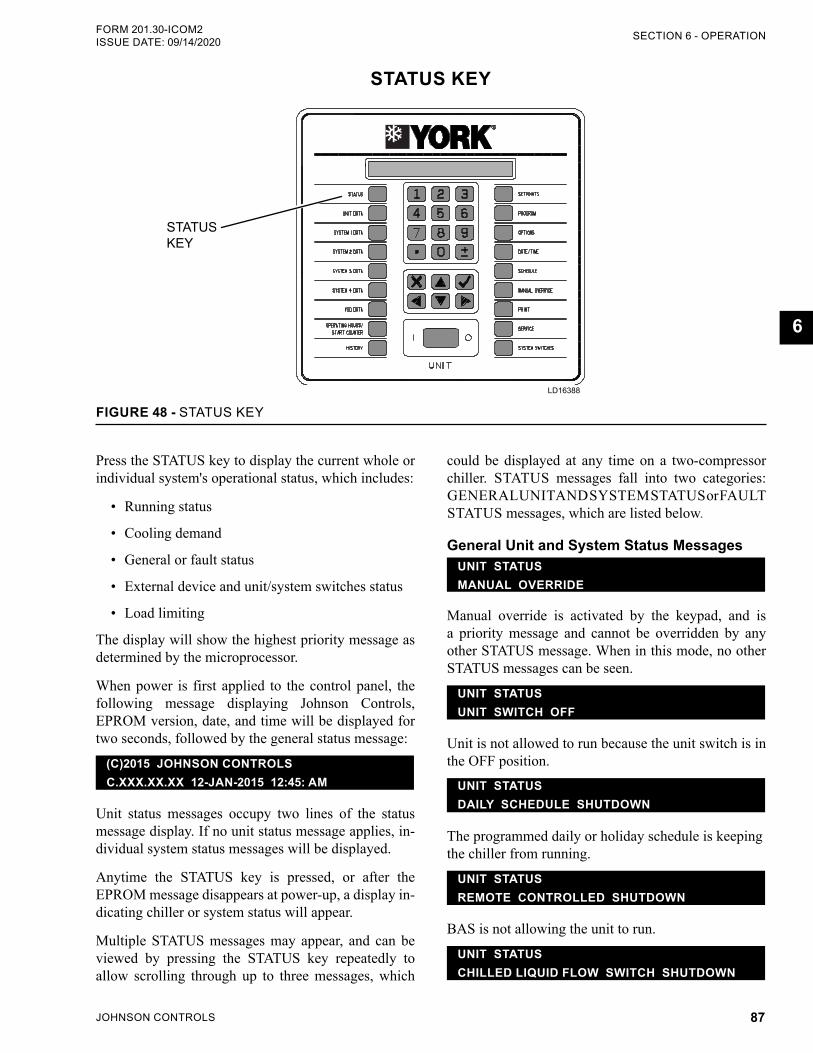
JOHNSON CONTROLS 87
SECTION 6 - OPERATIONFORM 201.30-ICOM2 ISSUE DATE: 09/14/2020
6
STATUS KEY
LD19539
STATUS KEY
FIGURE 48 - STATUS KEY
LD16388
could be displayed at any time on a two-compressor chiller. STATUS messages fall into two categories: GENERAL UNIT AND SYSTEM STATUS or FAULT STATUS messages, which are listed below.
General Unit and System Status MessagesUNIT STATUSMANUAL OVERRIDE
Manual override is activated by the keypad, and is a priority message and cannot be overridden by any other STATUS message. When in this mode, no other STATUS messages can be seen.
UNIT STATUS UNIT SWITCH OFF
Unit is not allowed to run because the unit switch is in the OFF position.
UNIT STATUS DAILY SCHEDULE SHUTDOWN
The programmed daily or holiday schedule is keeping the chiller from running.
UNIT STATUSREMOTE CONTROLLED SHUTDOWN
BAS is not allowing the unit to run.
UNIT STATUSCHILLED LIQUID FLOW SWITCH SHUTDOWN
Press the STATUS key to display the current whole or individual system's operational status, which includes:
• Running status
• Cooling demand
• General or fault status
• External device and unit/system switches status
• Load limiting
The display will show the highest priority message as determined by the microprocessor.
When power is first applied to the control panel, the following message displaying Johnson Controls, EPROM version, date, and time will be displayed for two seconds, followed by the general status message:
(C)2015 JOHNSON CONTROLSC.XXX.XX.XX 12-JAN-2015 12:45: AM
Unit status messages occupy two lines of the status message display. If no unit status message applies, in-dividual system status messages will be displayed.
Anytime the STATUS key is pressed, or after the EPROM message disappears at power-up, a display in-dicating chiller or system status will appear.
Multiple STATUS messages may appear, and can be viewed by pressing the STATUS key repeatedly to allow scrolling through up to three messages, which
JOHNSON CONTROLS88
FORM 201.30-ICOM2ISSUE DATE: 09/14/2020SECTION 6 - OPERATION
The system is ramping down to shut down. This mes-sage is displayed after the software run signal is disabled until the VSD notifies the control board that the com-pressor is no longer running.
SYS X ANTI-RECYCLE TIMER = ### SEC
The amount of time remaining on the anti-recycle tim-er is shown, and the system is unable to start due to the timer being active.
OPD MITIGATION
OPD is Oil Pressure Differential. Condenser level con-trol is repositioning the level setpoint to reduce evapo-rator pressure and overcome low differential pressure to maintain oil flow.
Load or Unloading Limit MessagesThe following messages show that the designated load limit or unloading is in effect.
SYS X DISCHARGE PRESSURE LIMITING
SYS X EVAPORATOR PRESSURE LIMITING
SYS X MOTOR CURRENT LIMITING
SYS X PULLDOWN MOTOR CURRENT LIMITING
SYS X BAS CURRENT LIMITING
The motor current load limit or unloading is in effect through the use of the BAS setpoint offset. The BAS current limit must be activated for this function to op-erate.
SYS X REMOTE MOTOR CURRENT LIMITING
The motor current load limit or unloading is in effect through the use of the remote setpoint offset, which may be offset using a remote voltage or a current sig-nal. The remote current limit must be activated for this function to operate.
SYS X VSD BASEPLATE TEMP LIMITING
The VSD baseplate temperature is high, resulting in load limiting or unloading.
The flow switch is open, which is preventing the unit from running. There is a one second delay until the unit shuts down.
UNIT STATUS CONDENSER LIQUID FLOW SWITCH SHUTDOWN
The flow switch is open, which is preventing the unit from running. There is a one second delay until the unit shuts down.
UNIT STATUS VSD COOLING SHUTDOWN
The chiller is shutdown, but is running the auxiliary coolant pump, to bring the VSD ambient temperature down to an acceptable level before allowing the unit to start.
SYS X REMOTE RUN CONTACT IS OPEN
The system remote run permissive input is open, pre-venting that system from running. There is a one sec-ond delay until the unit shuts down.
SYS X SYSTEM SWITCH IS OFF
The system is prevented from running by selecting OFF with the SYSTEM SWITCHES key.
SYS X NOT RUNNING
The chilled or condenser liquid temperature is below the setpoint, or the microprocessor has not loaded the lead system far enough into the loading sequence to bring on the lag system. This message will be dis-played on the lag system until the loading sequence is ready for the lag system to start. This message also applies to the Leaving Condenser Liquid Temperature and setpoint in the HEAT PUMP MODE.
SYS X COOLING DEMAND SHUTDOWN
This message is only displayed in NORMAL SHUT-DOWN HISTORY to indicate a capacity controlled shutdown based on cooling and heating demand.
SYS X COMPRESSOR RUNNING
The system is running due to demand.
SYS X SHUTTING DOWN
JOHNSON CONTROLS 89
SECTION 6 - OPERATIONFORM 201.30-ICOM2 ISSUE DATE: 09/14/2020
6
SYS X VSD INTERNAL AMBIENT TEMP LIMITING
The VSD internal ambient temperature is high, result-ing in load limiting or unloading.
SYS X CHILLED LIQ LEAVE TEMP LIMITING
Applicable in HEAT PUMP mode only.
FAULT MESSAGESA number of possible fault messages may appear when the STATUS key is pressed. Whenever a fault message appears, the safety thresholds on the unit have been ex-ceeded, the unit or a single system will be shut down, and, in some cases, locked out. The shutdown thresh-olds and associated information relating to each fault are explained in the UNIT WARNINGS, UNIT SAFE-TIES (FAULTS) and SYSTEM SAFETIES (FAULTS) sections.
Unit WarningsUnit warnings, as shown in Table 27 page 93, are caused when a condition is present requiring opera-tor intervention to restart the unit. Check all setpoints, program values, and options before operating the unit. Warnings are not logged into the history buffer. If a unit warning is in effect, the message will be displayed when the operator presses the STATUS key.
MICROBOARD (331-03478-XXX)The 331-03478-xxx microboard was developed as a direct replacement for the 031-02478-xxx line of microboards. No adapter harness is required when re-placing a 02478 with the new 03478. The 03478 uses the IPUII processor card and provides some new fea-tures for the chillers that the 02478 did not have.
The 03478 program resides in flash memory instead of EPROM. Program updates are accomplished by load-ing the new program from an SD card inserted into the SD card reader/writer. This same SD card reader/writer also allows the user to datalog the operating param-eters to an SD card every 5 seconds. This information is invaluable when troubleshooting unit and system problems since it allows the service technician to view operating parameters before a unit fault. Details on the new datalogging capability are explained in the OP-TIONS Key area of this manual. A Real Time Clock/BRAM keeps time and setpoints during power out-tages.
Power Supplies and LEDsThe 03478 has LEDs to indicate various states of op-eration of the microboard.
STATUS – Flashes every ½ second to indicate that the base board processor is running its program.
POWER – On solid indicates that the base board +12 V and +5 V power supplies are operational.
TX1 – Red LED flashes when transmitting data out Port 1 TB3 (Future native communications BAS port)
RX1 – Green LED flashes when receiving data in Port 1 TB3 (Future native communications BAS port)
TX2 – Red LED that flashes when transmitting data out Port 2 (E-Link TB2 or printer TB1)
RX2 – Green LED that flashes when receiving data in Port 2 (E-Link TB2 or printer TB1)
VSD_TX – Red LED that flashes when transmitting data out Port 3 to the VSD Logic board
VSD_RX – Green LED that flashes when receiving data in Port 3 from the VSD Logic board
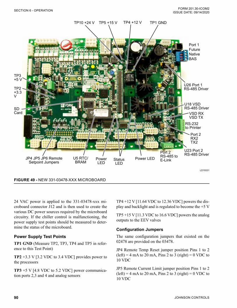
JOHNSON CONTROLS90
FORM 201.30-ICOM2ISSUE DATE: 09/14/2020SECTION 6 - OPERATION
FIGURE 49 - NEW 331-03478-XXX MICROBOARD
TP10 +24 V TP5 +15 V TP4 +12 V TP1 GND
U18 VSD RS-485 Driver
VSD RX VSD TX
Port 2 RX2 TX2
RS-232 to Printer
Power LEDStatus LED
TP3 +5 V
TP2 +3.3 V
SD Card
Power LED
U5 RTC/BRAM
JP4 JP5 JP6 Remote Setpoint Jumpers
Port 2 RS-485 to E-Link
U26 Port 1 RS-485 Driver
U23 Port 2 RS-485 Driver
Port 1 Future Native BAS
LD19331
24 VAC power is applied to the 331-03478-xxx mi-croboard connector J12 and is then used to create the various DC power sources required by the microboard circuitry. If the chiller control is malfunctioning, the power supply test points should be measured to deter-mine the status of the microboard.
Power Supply Test PointsTP1 GND (Measure TP2, TP3, TP4 and TP5 in refer-ence to this Test Point)
TP2 +3.3 V [3.2 VDC to 3.4 VDC] provides power to the processors
TP3 +5 V [4.8 VDC to 5.2 VDC] power communica-tion ports 2,3 and 4 and analog sensors
TP4 +12 V [11.64 VDC to 12.36 VDC] powers the dis-play and backlight and is regulated to become the +5 V
TP5 +15 V [11.3 VDC to 16.6 VDC] powers the analog outputs to the EEV valves
Configuration Jumpers The same configuration jumpers that existed on the 02478 are provided on the 03478.
JP4 Remote Temp Reset jumper position Pins 1 to 2 (left) = 4 mA to 20 mA, Pins 2 to 3 (right) = 0 VDC to 10 VDC
JP5 Remote Current Limit jumper position Pins 1 to 2 (left) = 4 mA to 20 mA, Pins 2 to 3 (right) = 0 VDC to 10 VDC
JOHNSON CONTROLS 91
SECTION 6 - OPERATIONFORM 201.30-ICOM2 ISSUE DATE: 09/14/2020
6
JP6 Remote Sound Limit jumper position (Pins 1 to 2 (left) = 4 mA to 20 mA, Pins 2 to 3 (right) = 0 VDC to 10 VDC
Communication PortsTB3 Port 1 Future Native BAS RS-485.
SW1 RS-485 Biasing Switch for Port. Set to ON if Chiller is in an End Of Line position on the network.
U26 is the Port 1 RS-485 Driver Chip. It is socketed to allow field replacement. RX1 and TX1 LEDs illumi-nate to indicate Port 1 communications activity.
E-LinkSW2 RS-485 Biasing Switch for E-link Port 2, should be in the OFF position.
TB2 is the Port 2 RS-485 E-Link Communications Port. RX2 and TX2 LEDs illuminate to indicate the Port 2 communications activity. U23 is the Port 2 RS-485 Driver Chip. It is socketed to allow field replace-ment. J16 provides +12VDC to power the E-Link.
VSDJ2 VSD#1 and J1 VSD#2 connections headers for RS-485 communications to the Variable Speed Drives.
VSD RX and VSD TX LEDs illuminate to indicate the VSD communications activity. U18 is the VSD Port RS-485 Driver Chip. It is socketed to allow field re-placement.
PROGRAM UPDATEThe Application software and BACnet database are stored in the IPU II Flash memory. Copying a new ver-sion of software and/or database from the SD Flash card changes the IPU II Flash. The new application software must be named SOFTWARE.BIN. The new BACnet database must be named DATABASE.BIN. These files must be located in the root directory of the SD Flash card. The software can be updated without updating the database. In this case, the existing data-base will be used with the new software. The database cannot be updated without updating the software.
To update the Program:
1. Copy the new software in to the root directory of the SD card.
2. Rename this new program file SOFTWARE.BIN.
3. Turn the Unit Switch OFF.
4. Insert the SD card in to the SD card Reader/Writer slot.
5. Press the OPTIONS Key and then press the Down Arrow Key until FLASH CARD UPDATE DIS-ABLED is displayed.
6. Press the RIGHT ARROW Key to change the DISABLED to ENABLED.
7. Press the ENTER Key to start the update. Once the ENTER Key is pressed, the message FLASH CARD UPDATING PLEASE WAIT... is dis-played until the update has been completed. The keypad and display will not respond during the flash update.
Do not reset or power down the chiller until the update is finished. Interrupting the Flash Update procedure can corrupt the program file and render the control board inoperative.
8. After the software is finished updating, the con-troller will automatically reboot.
9. If an error occurs during the update, an error mes-sage will be displayed where XXXX is the Error Code
TABLE 25 - FLASH CARD UPDATE ERROR XXXXXFLASH CARD
UPDATE ERROR CODE
DEFINITION
0 Okay10 Flash card not found.11 SOFTWARE.BIN file not found14 SOFTWARE.BIN file larger than expected.
15 RAM to IPU Flash transfer of DATABASE.BIN failed.
16 RAM to IPU Flash transfer of SOFTWARE.BIN failed.
17 Could not allocate sufficient memory to read or write file.
99 Internal software error.
10. After the update is completed and the controller reboots, the keypad and display will return to full functionality. The SD card may be left in place for datalogging or else replaced with another SD card dedicated for datalogging.
11. To remove the SD card, GENTLY press the card in slightly then release the pressure. The card should then pop out slightly to allow removal.
JOHNSON CONTROLS92
FORM 201.30-ICOM2ISSUE DATE: 09/14/2020SECTION 6 - OPERATION
DATA LOGGINGA 2GB SD card (p/n 031-03466-000) may be inserted into the 03478 IPUII SD card slot to record the chiller operating parameters at 5 second intervals. The data is stored in a folder named RMYYYYMM where YYYY is the year and MM is the month the data was recorded. The controller creates a file for each day within this folder with the format YYYYMMDD.csv where DD equals the day of the month in addition to the Y Year and M Month fields. For example: The folder named RM201503 is a folder created in March of 2015. Within this folder would be a file for each day of that month that the datalogging is running. If a review of the History Report shows that an abnormal event oc-curred on March 3rd at 2:05pm, the user can import the 20150303.csv file into Excel and look at the system parameter details leading up to the 2:05pm event.
Follow all JCI Safety Directives when in-serting or removing the SD card since the card is located inside the control cabinet.
To start the Data Logging, insert the SD card into the SD card slot on the 03478 IPUII board. The label on the SD card should be facing outwards.
Once the SD card is inserted and the unit is powered up, press the OPTIONS key. Then press the Down Ar-row key to advance to the DATA LOG TO FLASH-CARD selection. Next press the Right Arrow key to select ON then press the ENTER key to start the Data Log. A 2GB SD card will hold about 8 months worth of data. A smaller card may be used that will hold less data but should be tested for compatibility. The con-troller operating system does not support SD cards larger than 2GB. When the SD card becomes full, the oldest date file is automatically deleted and a new day log file is written in its place.
To stop the data logging and retrieve the SD card, press the OPTION key and then the Down Arrow key to dis-play the DATA LOG TO FLASHCARD option and then use the Right Arrow key to select OFF then press the ENTER key.
Again, follow the JCI Safety Directives to stop the chiller, power off the unit and open the control cabiner door to retrieve the SD card.
Once inside the control cabinet, lightly press in on the SD card and then release the pressure. The SD card should pop out slightly to allow removal. You may then copy the files to a PC for analysis or email the file to someone. The files are saved as a CSV format which can be read by Excel. Below is a sample of some of the data imported from a YCIV Chiller. Once the file is read in to Excel, you can hide unrelated col-umns or plot preferred parameters to analyze the data.
TABLE 26 - DATA LOGGING
HOUR MIN SEC
SYS 1 SUCT PRESS
SYS 1 DSCH PRESS
SYS 1 OIL
PRESS
SYS 1 SUCT TEMP
SYS 1 SAT SUCT TEMP
SYS 1 SUCT
SHEAT
SYS 1 MTR
CURR FLA
SYS 1 DSCH TEMP
SYS 1 SAT DSCH TEMP
SYS 1 DSCH SHEAT
SYS 1 OIL TEMP
SYS 1 COMP
STATUSSYS 1 ECON
SYS 1 FAN STAGE
SYS 1 MOTOR TEMP1
PSIG PSIG PSIG °F °F °F A °F °F °F °F °F
0 0 10 82.6 84.4 84.4 93 77.5 15.5 0 83 78.6 4.4 82 OFF OFF 0 107.9
11 0 15 82.6 84.4 84.4 93 77.5 15.5 0 83 78.6 4.4 82 OFF OFF 0 107.9
11 22 20 82.6 84.4 84.4 93 77.5 15.5 0 83 78.6 4.4 82 OFF OFF 0 107.9
11 22 25 82.6 84.4 84.4 93 77.5 15.5 0 83 78.6 4.4 82 OFF OFF 0 107.9
11 22 30 82.6 84.4 84.4 93 77.5 15.5 0 83 78.6 4.4 82 OFF OFF 0 107.9
11 22 35 82.5 84.4 84.4 93 77.4 15.6 0 83 78.6 4.4 82 OFF OFF 0 107.9
JOHNSON CONTROLS 93
SECTION 6 - OPERATIONFORM 201.30-ICOM2 ISSUE DATE: 09/14/2020
6
TABLE 27 - UNIT WARNINGSMESSAGE DESCRIPTION
OIL FILTER CLOGGED
This message alerts low oil flow, possibly from a clogged oil filter. A system will not shutdown when its high oil filter differential pressure (Oil Pressure - Discharge Pressure) rises above the programmable setpoint (10 to 100 psid, default 20 psid). The message will be cleared when the pressure drops below setpoint or the compressor is stopped. The message, SYS X, applies to System 1 or 2.
INVALID NUMBER OF COMPRESSORS
SELECTED
This message, which will be displayed indefinitely, checks a jumper in the VSD wiring harness, which indicates the number of compressors. The message will occur after the VSD has been initialized on power-up, if no jumpers are installed, or if more than one jumper is installed. To clear this warning, turn off the control panel and VSD control voltage, and install the jumpers properly in the VSD wiring harness.
These jumpers are factory installed in the wire harness plug and should not require changes.
INVALID SERIAL NUMBER
If this message appears, which indicates an invalid letter or number exists in a location in the serial number string, the chiller may have lost important factory programmed information. Contact Johnson Controls Product Technical Support immediately to get the password to enter the serial number using the SERVICE key. Bypass this status message to view additional messages by pressing the STATUS key repeatedly. Up to three STATUS messages can be displayed at any time.
LOW BATTERY
On power-up, the control system checks the RTC battery to see if it is still operational. If it is, normal unit operation is allowed. If the battery voltage is low, the warning message is displayed indefinitely. If a low battery condition exists, all programmed setpoints, program values, time, schedule, and history buffers were lost, which will be reset to their default values, which may not be the preferred operating values. Once a bad battery is detected, the unit will be prevented from running until the MANUAL OVERRIDE key is pressed. After the key is pressed, the anti-recycle timers will reset to allow the operator sufficient time to check setpoints, program values, etc.If a low battery is detected, replace it as soon as possible. The unit will be prevented from running on the next power interruption.
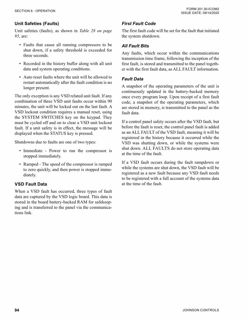
JOHNSON CONTROLS94
FORM 201.30-ICOM2ISSUE DATE: 09/14/2020SECTION 6 - OPERATION
Unit Safeties (Faults)Unit safeties (faults), as shown in Table 28 on page 95, are:
• Faults that cause all running compressors to be shut down, if a safety threshold is exceeded for three seconds.
• Recorded in the history buffer along with all unit data and system operating conditions.
• Auto reset faults where the unit will be allowed to restart automatically after the fault condition is no longer present.
The only exception is any VSD related unit fault. If any combination of three VSD unit faults occur within 90 minutes, the unit will be locked out on the last fault. A VSD lockout condition requires a manual reset, using the SYSTEM SWITCHES key on the keypad. They must be cycled off and on to clear a VSD unit lockout fault. If a unit safety is in effect, the message will be displayed when the STATUS key is pressed.
Shutdowns due to faults are one of two types:
• Immediate - Power to run the compressor is stopped immediately.
• Ramped - The speed of the compressor is ramped to zero quickly, and then power is stopped imme-diately.
VSD Fault DataWhen a VSD fault has occurred, three types of fault data are captured by the VSD logic board. This data is stored in the board battery-backed RAM for safekeep-ing and is transferred to the panel via the communica-tions link.
First Fault CodeThe first fault code will be set for the fault that initiated the system shutdown.
All Fault BitsAny faults, which occur within the communications transmission time frame, following the inception of the first fault, is stored and transmitted to the panel togeth-er with the first fault data, as ALL FAULT information.
Fault DataA snapshot of the operating parameters of the unit is continuously updated in the battery-backed memory once every program loop. Upon receipt of a first fault code, a snapshot of the operating parameters, which are stored in memory, is transmitted to the panel as the fault data.
If a control panel safety occurs after the VSD fault, but before the fault is reset, the control panel fault is added as an ALL FAULT of the VSD fault, meaning it will be registered in the history because it occurred while the VSD was shutting down, or while the systems were shut down. ALL FAULTS do not store operating data at the time of the fault.
If a VSD fault occurs during the fault rampdown or while the systems are shut down, the VSD fault will be registered as a new fault because any VSD fault needs to be registered with a full account of the systems data at the time of the fault.
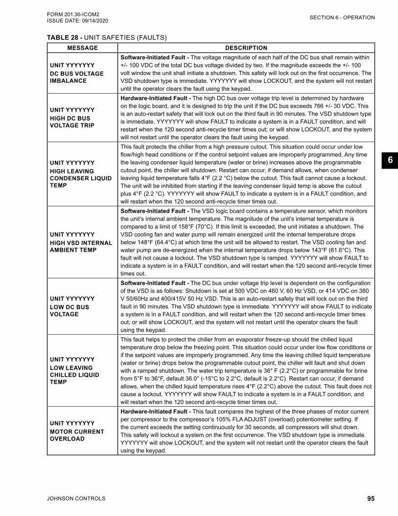
JOHNSON CONTROLS 95
SECTION 6 - OPERATIONFORM 201.30-ICOM2 ISSUE DATE: 09/14/2020
6
TABLE 28 - UNIT SAFETIES (FAULTS)MESSAGE DESCRIPTION
UNIT YYYYYYYDC BUS VOLTAGE IMBALANCE
Software-Initiated Fault - The voltage magnitude of each half of the DC bus shall remain within +/- 100 VDC of the total DC bus voltage divided by two. If the magnitude exceeds the +/- 100 volt window the unit shall initiate a shutdown. This safety will lock out on the first occurrence. The VSD shutdown type is immediate. YYYYYYY will show LOCKOUT, and the system will not restart until the operator clears the fault using the keypad.
UNIT YYYYYYY HIGH DC BUS VOLTAGE TRIP
Hardware-Initiated Fault - The high DC bus over voltage trip level is determined by hardware on the logic board, and it is designed to trip the unit if the DC bus exceeds 766 +/- 30 VDC. This is an auto-restart safety that will lock out on the third fault in 90 minutes. The VSD shutdown type is immediate. YYYYYYY will show FAULT to indicate a system is in a FAULT condition, and will restart when the 120 second anti-recycle timer times out; or will show LOCKOUT, and the system will not restart until the operator clears the fault using the keypad.
UNIT YYYYYYY HIGH LEAVING CONDENSER LIQUID TEMP
This fault protects the chiller from a high pressure cutout. This situation could occur under low flow/high head conditions or if the control setpoint values are improperly programmed. Any time the leaving condenser liquid temperature (water or brine) increases above the programmable cutout point, the chiller will shutdown. Restart can occur, if demand allows, when condenser leaving liquid temperature falls 4°F (2.2 °C) below the cutout. This fault cannot cause a lockout. The unit will be inhibited from starting if the leaving condenser liquid temp is above the cutout plus 4°F (2.2 °C). YYYYYYY will show FAULT to indicate a system is in a FAULT condition, and will restart when the 120 second anti-recycle timer times out.
UNIT YYYYYYY HIGH VSD INTERNAL AMBIENT TEMP
Software-Initiated Fault - The VSD logic board contains a temperature sensor, which monitors the unit’s internal ambient temperature. The magnitude of the unit’s internal temperature is compared to a limit of 158°F (70°C). If this limit is exceeded, the unit initiates a shutdown. The VSD cooling fan and water pump will remain energized until the internal temperature drops below 148°F (64.4°C) at which time the unit will be allowed to restart. The VSD cooling fan and water pump are de-energized when the internal temperature drops below 143°F (61.6°C). This fault will not cause a lockout. The VSD shutdown type is ramped. YYYYYYY will show FAULT to indicate a system is in a FAULT condition, and will restart when the 120 second anti-recycle timer times out.
UNIT YYYYYYY LOW DC BUS VOLTAGE
Software-Initiated Fault - The DC bus under voltage trip level is dependent on the configuration of the VSD is as follows: Shutdown is set at 500 VDC on 460 V, 60 Hz VSD, or 414 VDC on 380 V 50/60Hz and 400/415V 50 Hz VSD. This is an auto-restart safety that will lock out on the third fault in 90 minutes. The VSD shutdown type is immediate. YYYYYYY will show FAULT to indicate a system is in a FAULT condition, and will restart when the 120 second anti-recycle timer times out; or will show LOCKOUT, and the system will not restart until the operator clears the fault using the keypad.
UNIT YYYYYYY LOW LEAVING CHILLED LIQUID TEMP
This fault helps to protect the chiller from an evaporator freeze-up should the chilled liquid temperature drop below the freezing point. This situation could occur under low flow conditions or if the setpoint values are improperly programmed. Any time the leaving chilled liquid temperature (water or brine) drops below the programmable cutout point, the chiller will fault and shut down with a ramped shutdown. The water trip temperature is 36° F (2.2°C) or programmable for brine from 5°F to 36°F, default 36.0° (-15°C to 2.2°C, default is 2.2°C). Restart can occur, if demand allows, when the chilled liquid temperature rises 4°F (2.2°C) above the cutout. This fault does not cause a lockout. YYYYYYY will show FAULT to indicate a system is in a FAULT condition, and will restart when the 120 second anti-recycle timer times out.
UNIT YYYYYYY MOTOR CURRENT OVERLOAD
Hardware-Initiated Fault - This fault compares the highest of the three phases of motor current per compressor to the compressor’s 105% FLA ADJUST (overload) potentiometer setting. If the current exceeds the setting continuously for 30 seconds, all compressors will shut down. This safety will lockout a system on the first occurrence. The VSD shutdown type is immediate. YYYYYYY will show LOCKOUT, and the system will not restart until the operator clears the fault using the keypad.
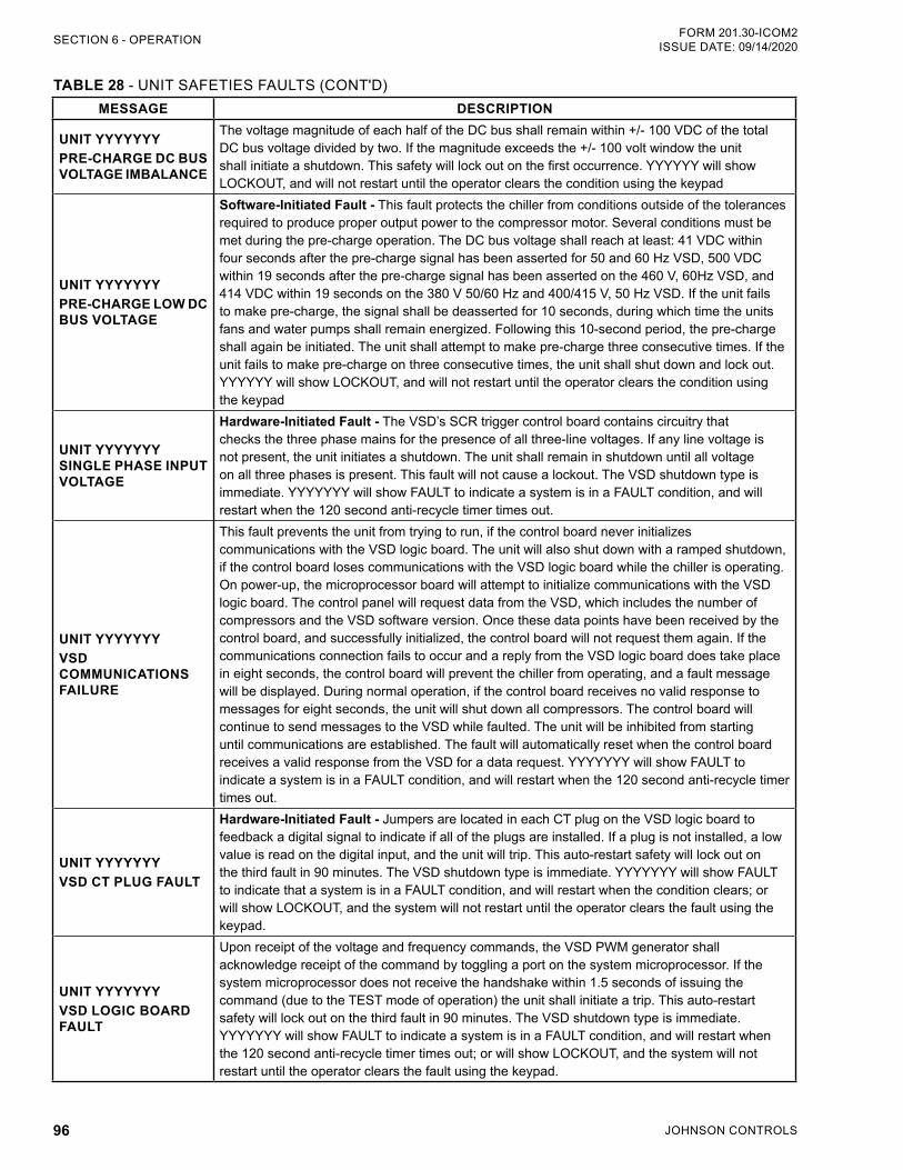
JOHNSON CONTROLS96
FORM 201.30-ICOM2ISSUE DATE: 09/14/2020SECTION 6 - OPERATION
TABLE 28 - UNIT SAFETIES FAULTS (CONT'D)MESSAGE DESCRIPTION
UNIT YYYYYYY PRE-CHARGE DC BUS VOLTAGE IMBALANCE
The voltage magnitude of each half of the DC bus shall remain within +/- 100 VDC of the total DC bus voltage divided by two. If the magnitude exceeds the +/- 100 volt window the unit shall initiate a shutdown. This safety will lock out on the first occurrence. YYYYYY will show LOCKOUT, and will not restart until the operator clears the condition using the keypad
UNIT YYYYYYY PRE-CHARGE LOW DC BUS VOLTAGE
Software-Initiated Fault - This fault protects the chiller from conditions outside of the tolerances required to produce proper output power to the compressor motor. Several conditions must be met during the pre-charge operation. The DC bus voltage shall reach at least: 41 VDC within four seconds after the pre-charge signal has been asserted for 50 and 60 Hz VSD, 500 VDC within 19 seconds after the pre-charge signal has been asserted on the 460 V, 60Hz VSD, and 414 VDC within 19 seconds on the 380 V 50/60 Hz and 400/415 V, 50 Hz VSD. If the unit fails to make pre-charge, the signal shall be deasserted for 10 seconds, during which time the units fans and water pumps shall remain energized. Following this 10-second period, the pre-charge shall again be initiated. The unit shall attempt to make pre-charge three consecutive times. If the unit fails to make pre-charge on three consecutive times, the unit shall shut down and lock out. YYYYYY will show LOCKOUT, and will not restart until the operator clears the condition using the keypad
UNIT YYYYYYY SINGLE PHASE INPUT VOLTAGE
Hardware-Initiated Fault - The VSD’s SCR trigger control board contains circuitry that checks the three phase mains for the presence of all three-line voltages. If any line voltage is not present, the unit initiates a shutdown. The unit shall remain in shutdown until all voltage on all three phases is present. This fault will not cause a lockout. The VSD shutdown type is immediate. YYYYYYY will show FAULT to indicate a system is in a FAULT condition, and will restart when the 120 second anti-recycle timer times out.
UNIT YYYYYYY VSD COMMUNICATIONS FAILURE
This fault prevents the unit from trying to run, if the control board never initializes communications with the VSD logic board. The unit will also shut down with a ramped shutdown, if the control board loses communications with the VSD logic board while the chiller is operating.On power-up, the microprocessor board will attempt to initialize communications with the VSD logic board. The control panel will request data from the VSD, which includes the number of compressors and the VSD software version. Once these data points have been received by the control board, and successfully initialized, the control board will not request them again. If the communications connection fails to occur and a reply from the VSD logic board does take place in eight seconds, the control board will prevent the chiller from operating, and a fault message will be displayed. During normal operation, if the control board receives no valid response to messages for eight seconds, the unit will shut down all compressors. The control board will continue to send messages to the VSD while faulted. The unit will be inhibited from starting until communications are established. The fault will automatically reset when the control board receives a valid response from the VSD for a data request. YYYYYYY will show FAULT to indicate a system is in a FAULT condition, and will restart when the 120 second anti-recycle timer times out.
UNIT YYYYYYY VSD CT PLUG FAULT
Hardware-Initiated Fault - Jumpers are located in each CT plug on the VSD logic board to feedback a digital signal to indicate if all of the plugs are installed. If a plug is not installed, a low value is read on the digital input, and the unit will trip. This auto-restart safety will lock out on the third fault in 90 minutes. The VSD shutdown type is immediate. YYYYYYY will show FAULT to indicate that a system is in a FAULT condition, and will restart when the condition clears; or will show LOCKOUT, and the system will not restart until the operator clears the fault using the keypad.
UNIT YYYYYYY VSD LOGIC BOARD FAULT
Upon receipt of the voltage and frequency commands, the VSD PWM generator shall acknowledge receipt of the command by toggling a port on the system microprocessor. If the system microprocessor does not receive the handshake within 1.5 seconds of issuing the command (due to the TEST mode of operation) the unit shall initiate a trip. This auto-restart safety will lock out on the third fault in 90 minutes. The VSD shutdown type is immediate. YYYYYYY will show FAULT to indicate a system is in a FAULT condition, and will restart when the 120 second anti-recycle timer times out; or will show LOCKOUT, and the system will not restart until the operator clears the fault using the keypad.
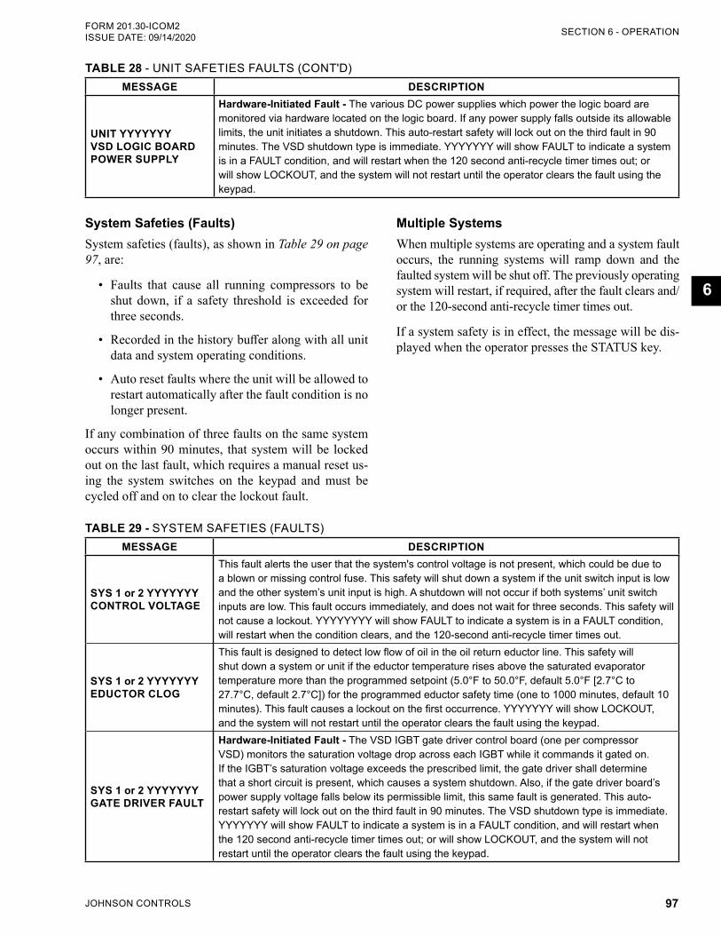
JOHNSON CONTROLS 97
SECTION 6 - OPERATIONFORM 201.30-ICOM2 ISSUE DATE: 09/14/2020
6
System Safeties (Faults)System safeties (faults), as shown in Table 29 on page 97, are:
• Faults that cause all running compressors to be shut down, if a safety threshold is exceeded for three seconds.
• Recorded in the history buffer along with all unit data and system operating conditions.
• Auto reset faults where the unit will be allowed to restart automatically after the fault condition is no longer present.
If any combination of three faults on the same system occurs within 90 minutes, that system will be locked out on the last fault, which requires a manual reset us-ing the system switches on the keypad and must be cycled off and on to clear the lockout fault.
Multiple Systems When multiple systems are operating and a system fault occurs, the running systems will ramp down and the faulted system will be shut off. The previously operating system will restart, if required, after the fault clears and/or the 120-second anti-recycle timer times out.
If a system safety is in effect, the message will be dis-played when the operator presses the STATUS key.
TABLE 29 - SYSTEM SAFETIES (FAULTS)MESSAGE DESCRIPTION
SYS 1 or 2 YYYYYYY CONTROL VOLTAGE
This fault alerts the user that the system's control voltage is not present, which could be due to a blown or missing control fuse. This safety will shut down a system if the unit switch input is low and the other system’s unit input is high. A shutdown will not occur if both systems’ unit switch inputs are low. This fault occurs immediately, and does not wait for three seconds. This safety will not cause a lockout. YYYYYYYY will show FAULT to indicate a system is in a FAULT condition, will restart when the condition clears, and the 120-second anti-recycle timer times out.
SYS 1 or 2 YYYYYYY EDUCTOR CLOG
This fault is designed to detect low flow of oil in the oil return eductor line. This safety will shut down a system or unit if the eductor temperature rises above the saturated evaporator temperature more than the programmed setpoint (5.0°F to 50.0°F, default 5.0°F [2.7°C to 27.7°C, default 2.7°C]) for the programmed eductor safety time (one to 1000 minutes, default 10 minutes). This fault causes a lockout on the first occurrence. YYYYYYY will show LOCKOUT, and the system will not restart until the operator clears the fault using the keypad.
SYS 1 or 2 YYYYYYY GATE DRIVER FAULT
Hardware-Initiated Fault - The VSD IGBT gate driver control board (one per compressor VSD) monitors the saturation voltage drop across each IGBT while it commands it gated on. If the IGBT’s saturation voltage exceeds the prescribed limit, the gate driver shall determine that a short circuit is present, which causes a system shutdown. Also, if the gate driver board’s power supply voltage falls below its permissible limit, this same fault is generated. This auto-restart safety will lock out on the third fault in 90 minutes. The VSD shutdown type is immediate. YYYYYYY will show FAULT to indicate a system is in a FAULT condition, and will restart when the 120 second anti-recycle timer times out; or will show LOCKOUT, and the system will not restart until the operator clears the fault using the keypad.
TABLE 28 - UNIT SAFETIES FAULTS (CONT'D)MESSAGE DESCRIPTION
UNIT YYYYYYY VSD LOGIC BOARD POWER SUPPLY
Hardware-Initiated Fault - The various DC power supplies which power the logic board are monitored via hardware located on the logic board. If any power supply falls outside its allowable limits, the unit initiates a shutdown. This auto-restart safety will lock out on the third fault in 90 minutes. The VSD shutdown type is immediate. YYYYYYY will show FAULT to indicate a system is in a FAULT condition, and will restart when the 120 second anti-recycle timer times out; or will show LOCKOUT, and the system will not restart until the operator clears the fault using the keypad.
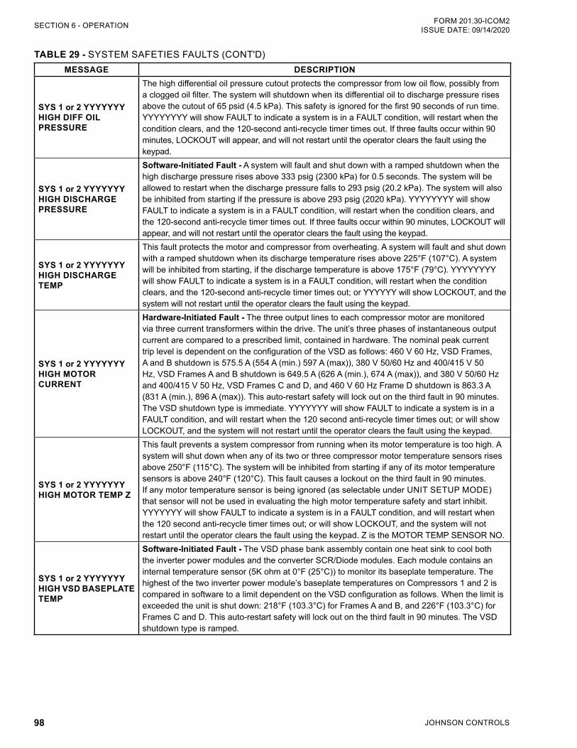
JOHNSON CONTROLS98
FORM 201.30-ICOM2ISSUE DATE: 09/14/2020SECTION 6 - OPERATION
MESSAGE DESCRIPTION
SYS 1 or 2 YYYYYYY HIGH DIFF OIL PRESSURE
The high differential oil pressure cutout protects the compressor from low oil flow, possibly from a clogged oil filter. The system will shutdown when its differential oil to discharge pressure rises above the cutout of 65 psid (4.5 kPa). This safety is ignored for the first 90 seconds of run time. YYYYYYYY will show FAULT to indicate a system is in a FAULT condition, will restart when the condition clears, and the 120-second anti-recycle timer times out. If three faults occur within 90 minutes, LOCKOUT will appear, and will not restart until the operator clears the fault using the keypad.
SYS 1 or 2 YYYYYYY HIGH DISCHARGE PRESSURE
Software-Initiated Fault - A system will fault and shut down with a ramped shutdown when the high discharge pressure rises above 333 psig (2300 kPa) for 0.5 seconds. The system will be allowed to restart when the discharge pressure falls to 293 psig (20.2 kPa). The system will also be inhibited from starting if the pressure is above 293 psig (2020 kPa). YYYYYYYY will show FAULT to indicate a system is in a FAULT condition, will restart when the condition clears, and the 120-second anti-recycle timer times out. If three faults occur within 90 minutes, LOCKOUT will appear, and will not restart until the operator clears the fault using the keypad.
SYS 1 or 2 YYYYYYY HIGH DISCHARGE TEMP
This fault protects the motor and compressor from overheating. A system will fault and shut down with a ramped shutdown when its discharge temperature rises above 225°F (107°C). A system will be inhibited from starting, if the discharge temperature is above 175°F (79°C). YYYYYYYY will show FAULT to indicate a system is in a FAULT condition, will restart when the condition clears, and the 120-second anti-recycle timer times out; or YYYYYY will show LOCKOUT, and the system will not restart until the operator clears the fault using the keypad.
SYS 1 or 2 YYYYYYY HIGH MOTOR CURRENT
Hardware-Initiated Fault - The three output lines to each compressor motor are monitored via three current transformers within the drive. The unit’s three phases of instantaneous output current are compared to a prescribed limit, contained in hardware. The nominal peak current trip level is dependent on the configuration of the VSD as follows: 460 V 60 Hz, VSD Frames, A and B shutdown is 575.5 A (554 A (min.) 597 A (max)), 380 V 50/60 Hz and 400/415 V 50 Hz, VSD Frames A and B shutdown is 649.5 A (626 A (min.), 674 A (max)), and 380 V 50/60 Hz and 400/415 V 50 Hz, VSD Frames C and D, and 460 V 60 Hz Frame D shutdown is 863.3 A (831 A (min.), 896 A (max)). This auto-restart safety will lock out on the third fault in 90 minutes. The VSD shutdown type is immediate. YYYYYYY will show FAULT to indicate a system is in a FAULT condition, and will restart when the 120 second anti-recycle timer times out; or will show LOCKOUT, and the system will not restart until the operator clears the fault using the keypad.
SYS 1 or 2 YYYYYYY HIGH MOTOR TEMP Z
This fault prevents a system compressor from running when its motor temperature is too high. A system will shut down when any of its two or three compressor motor temperature sensors rises above 250°F (115°C). The system will be inhibited from starting if any of its motor temperature sensors is above 240°F (120°C). This fault causes a lockout on the third fault in 90 minutes. If any motor temperature sensor is being ignored (as selectable under UNIT SETUP MODE) that sensor will not be used in evaluating the high motor temperature safety and start inhibit. YYYYYYY will show FAULT to indicate a system is in a FAULT condition, and will restart when the 120 second anti-recycle timer times out; or will show LOCKOUT, and the system will not restart until the operator clears the fault using the keypad. Z is the MOTOR TEMP SENSOR NO.
SYS 1 or 2 YYYYYYY HIGH VSD BASEPLATE TEMP
Software-Initiated Fault - The VSD phase bank assembly contain one heat sink to cool both the inverter power modules and the converter SCR/Diode modules. Each module contains an internal temperature sensor (5K ohm at 0°F (25°C)) to monitor its baseplate temperature. The highest of the two inverter power module’s baseplate temperatures on Compressors 1 and 2 is compared in software to a limit dependent on the VSD configuration as follows. When the limit is exceeded the unit is shut down: 218°F (103.3°C) for Frames A and B, and 226°F (103.3°C) for Frames C and D. This auto-restart safety will lock out on the third fault in 90 minutes. The VSD shutdown type is ramped.
TABLE 29 - SYSTEM SAFETIES FAULTS (CONT'D)
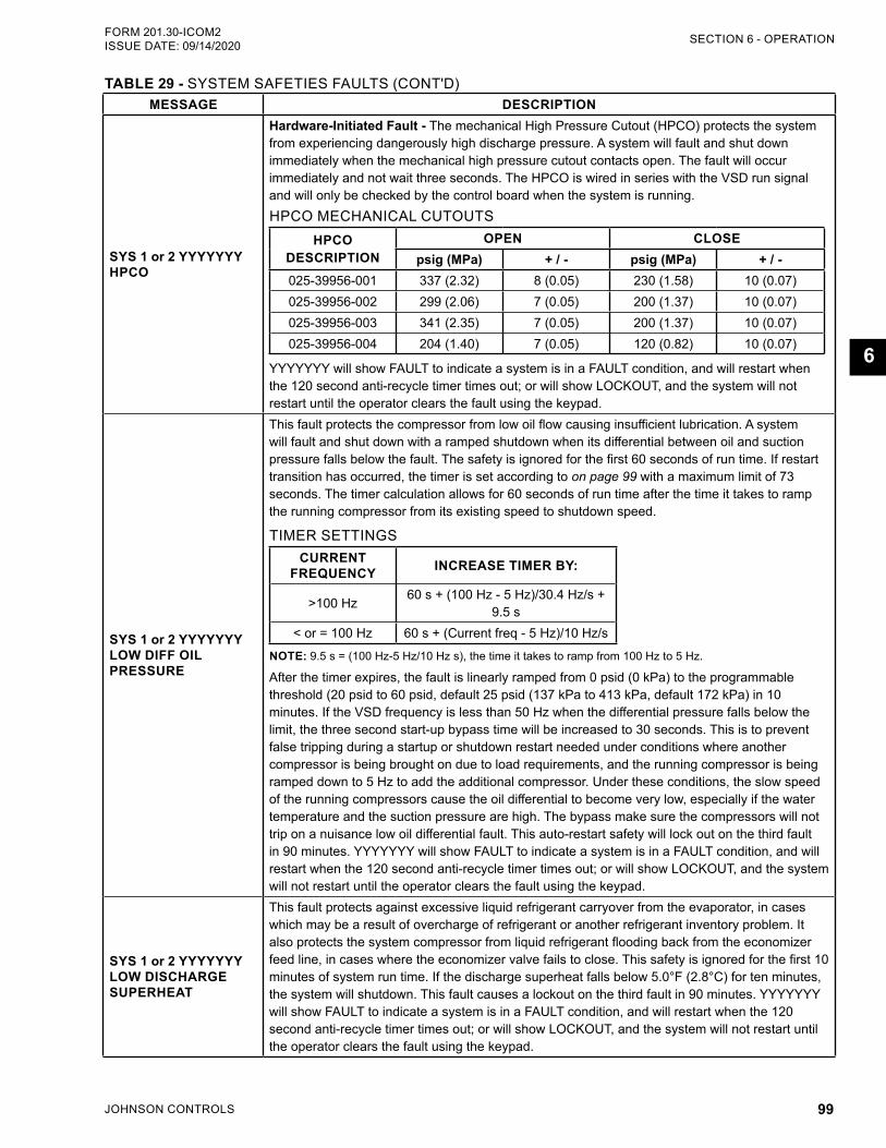
JOHNSON CONTROLS 99
SECTION 6 - OPERATIONFORM 201.30-ICOM2 ISSUE DATE: 09/14/2020
6
MESSAGE DESCRIPTION
SYS 1 or 2 YYYYYYY HPCO
Hardware-Initiated Fault - The mechanical High Pressure Cutout (HPCO) protects the system from experiencing dangerously high discharge pressure. A system will fault and shut down immediately when the mechanical high pressure cutout contacts open. The fault will occur immediately and not wait three seconds. The HPCO is wired in series with the VSD run signal and will only be checked by the control board when the system is running. HPCO MECHANICAL CUTOUTS
HPCODESCRIPTION
OPEN CLOSEpsig (MPa) + / - psig (MPa) + / -
025-39956-001 337 (2.32) 8 (0.05) 230 (1.58) 10 (0.07)025-39956-002 299 (2.06) 7 (0.05) 200 (1.37) 10 (0.07)025-39956-003 341 (2.35) 7 (0.05) 200 (1.37) 10 (0.07)025-39956-004 204 (1.40) 7 (0.05) 120 (0.82) 10 (0.07)
YYYYYYY will show FAULT to indicate a system is in a FAULT condition, and will restart when the 120 second anti-recycle timer times out; or will show LOCKOUT, and the system will not restart until the operator clears the fault using the keypad.
SYS 1 or 2 YYYYYYY LOW DIFF OIL PRESSURE
This fault protects the compressor from low oil flow causing insufficient lubrication. A system will fault and shut down with a ramped shutdown when its differential between oil and suction pressure falls below the fault. The safety is ignored for the first 60 seconds of run time. If restart transition has occurred, the timer is set according to on page 99 with a maximum limit of 73 seconds. The timer calculation allows for 60 seconds of run time after the time it takes to ramp the running compressor from its existing speed to shutdown speed.
TIMER SETTINGSCURRENT
FREQUENCY INCREASE TIMER BY:
>100 Hz 60 s + (100 Hz - 5 Hz)/30.4 Hz/s + 9.5 s
< or = 100 Hz 60 s + (Current freq - 5 Hz)/10 Hz/s
NOTE: 9.5 s = (100 Hz-5 Hz/10 Hz s), the time it takes to ramp from 100 Hz to 5 Hz.
After the timer expires, the fault is linearly ramped from 0 psid (0 kPa) to the programmable threshold (20 psid to 60 psid, default 25 psid (137 kPa to 413 kPa, default 172 kPa) in 10 minutes. If the VSD frequency is less than 50 Hz when the differential pressure falls below the limit, the three second start-up bypass time will be increased to 30 seconds. This is to prevent false tripping during a startup or shutdown restart needed under conditions where another compressor is being brought on due to load requirements, and the running compressor is being ramped down to 5 Hz to add the additional compressor. Under these conditions, the slow speed of the running compressors cause the oil differential to become very low, especially if the water temperature and the suction pressure are high. The bypass make sure the compressors will not trip on a nuisance low oil differential fault. This auto-restart safety will lock out on the third fault in 90 minutes. YYYYYYY will show FAULT to indicate a system is in a FAULT condition, and will restart when the 120 second anti-recycle timer times out; or will show LOCKOUT, and the system will not restart until the operator clears the fault using the keypad.
SYS 1 or 2 YYYYYYY LOW DISCHARGE SUPERHEAT
This fault protects against excessive liquid refrigerant carryover from the evaporator, in cases which may be a result of overcharge of refrigerant or another refrigerant inventory problem. It also protects the system compressor from liquid refrigerant flooding back from the economizer feed line, in cases where the economizer valve fails to close. This safety is ignored for the first 10 minutes of system run time. If the discharge superheat falls below 5.0°F (2.8°C) for ten minutes, the system will shutdown. This fault causes a lockout on the third fault in 90 minutes. YYYYYYY will show FAULT to indicate a system is in a FAULT condition, and will restart when the 120 second anti-recycle timer times out; or will show LOCKOUT, and the system will not restart until the operator clears the fault using the keypad.
TABLE 29 - SYSTEM SAFETIES FAULTS (CONT'D)
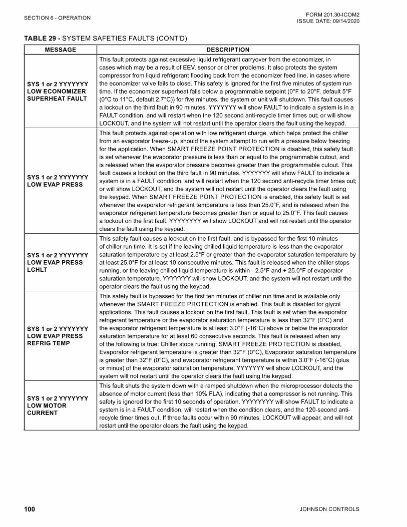
JOHNSON CONTROLS100
FORM 201.30-ICOM2ISSUE DATE: 09/14/2020SECTION 6 - OPERATION
MESSAGE DESCRIPTION
SYS 1 or 2 YYYYYYY LOW ECONOMIZER SUPERHEAT FAULT
This fault protects against excessive liquid refrigerant carryover from the economizer, in cases which may be a result of EEV, sensor or other problems. It also protects the system compressor from liquid refrigerant flooding back from the economizer feed line, in cases where the economizer valve fails to close. This safety is ignored for the first five minutes of system run time. If the economizer superheat falls below a programmable setpoint (0°F to 20°F, default 5°F (0°C to 11°C, default 2.7°C)) for five minutes, the system or unit will shutdown. This fault causes a lockout on the third fault in 90 minutes. YYYYYYY will show FAULT to indicate a system is in a FAULT condition, and will restart when the 120 second anti-recycle timer times out; or will show LOCKOUT, and the system will not restart until the operator clears the fault using the keypad.
SYS 1 or 2 YYYYYYY LOW EVAP PRESS
This fault protects against operation with low refrigerant charge, which helps protect the chiller from an evaporator freeze-up, should the system attempt to run with a pressure below freezing for the application. When SMART FREEZE POINT PROTECTION is disabled, this safety fault is set whenever the evaporator pressure is less than or equal to the programmable cutout, and is released when the evaporator pressure becomes greater than the programmable cutout. This fault causes a lockout on the third fault in 90 minutes. YYYYYYY will show FAULT to indicate a system is in a FAULT condition, and will restart when the 120 second anti-recycle timer times out; or will show LOCKOUT, and the system will not restart until the operator clears the fault using the keypad. When SMART FREEZE POINT PROTECTION is enabled, this safety fault is set whenever the evaporator refrigerant temperature is less than 25.0°F, and is released when the evaporator refrigerant temperature becomes greater than or equal to 25.0°F. This fault causes a lockout on the first fault. YYYYYYYY will show LOCKOUT and will not restart until the operator clears the fault using the keypad.
SYS 1 or 2 YYYYYYY LOW EVAP PRESS LCHLT
This safety fault causes a lockout on the first fault, and is bypassed for the first 10 minutes of chiller run time. It is set if the leaving chilled liquid temperature is less than the evaporator saturation temperature by at least 2.5°F or greater than the evaporator saturation temperature by at least 25.0°F for at least 10 consecutive minutes. This fault is released when the chiller stops running, or the leaving chilled liquid temperature is within - 2.5°F and + 25.0°F of evaporator saturation temperature. YYYYYYY will show LOCKOUT, and the system will not restart until the operator clears the fault using the keypad.
SYS 1 or 2 YYYYYYY LOW EVAP PRESS REFRIG TEMP
This safety fault is bypassed for the first ten minutes of chiller run time and is available only whenever the SMART FREEZE PROTECTION is enabled. This fault is disabled for glycol applications. This fault causes a lockout on the first fault. This fault is set when the evaporator refrigerant temperature or the evaporator saturation temperature is less than 32°F (0°C) and the evaporator refrigerant temperature is at least 3.0°F (-16°C) above or below the evaporator saturation temperature for at least 60 consecutive seconds. This fault is released when any of the following is true: Chiller stops running, SMART FREEZE PROTECTION is disabled, Evaporator refrigerant temperature is greater than 32°F (0°C), Evaporator saturation temperature is greater than 32°F (0°C), and evaporator refrigerant temperature is within 3.0°F (-16°C) (plus or minus) of the evaporator saturation temperature. YYYYYYY will show LOCKOUT, and the system will not restart until the operator clears the fault using the keypad.
SYS 1 or 2 YYYYYYY LOW MOTOR CURRENT
This fault shuts the system down with a ramped shutdown when the microprocessor detects the absence of motor current (less than 10% FLA), indicating that a compressor is not running. This safety is ignored for the first 10 seconds of operation. YYYYYYYY will show FAULT to indicate a system is in a FAULT condition, will restart when the condition clears, and the 120-second anti-recycle timer times out. If three faults occur within 90 minutes, LOCKOUT will appear, and will not restart until the operator clears the fault using the keypad.
TABLE 29 - SYSTEM SAFETIES FAULTS (CONT'D)
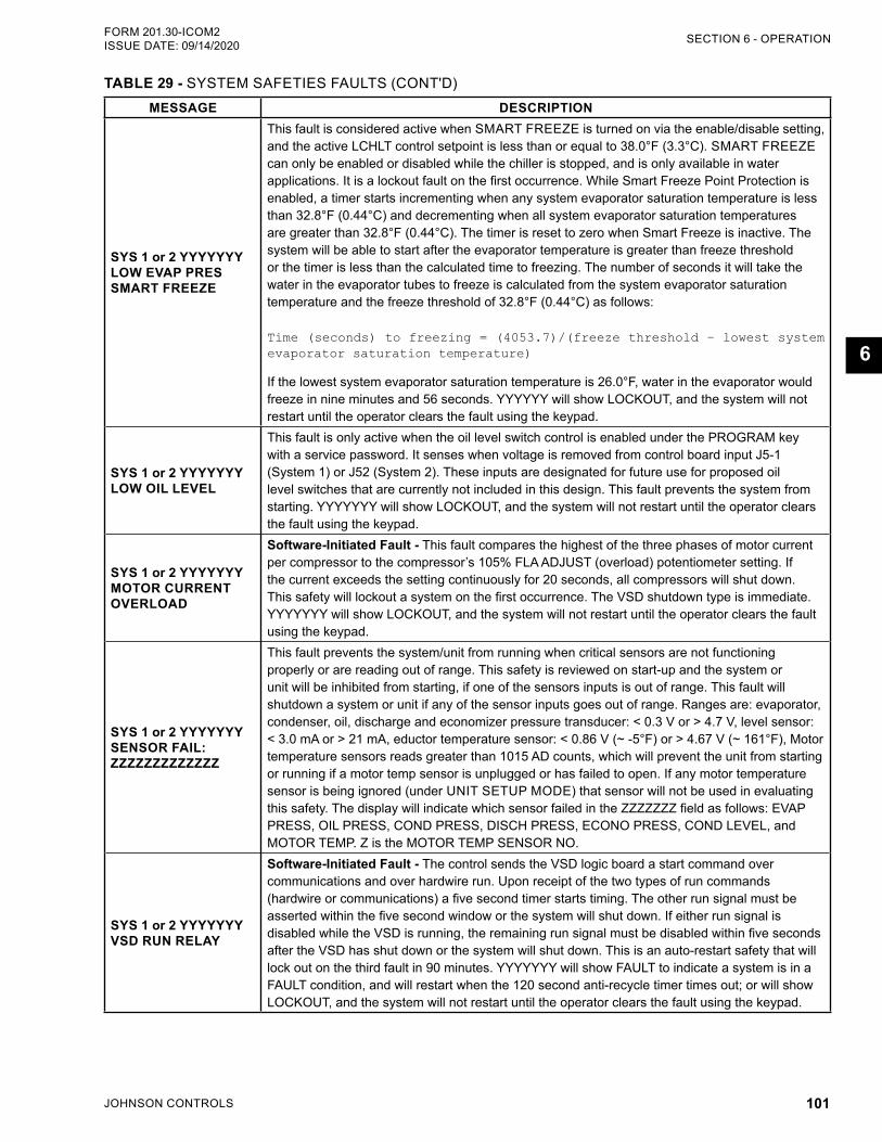
JOHNSON CONTROLS 101
SECTION 6 - OPERATIONFORM 201.30-ICOM2 ISSUE DATE: 09/14/2020
6
MESSAGE DESCRIPTION
SYS 1 or 2 YYYYYYY LOW EVAP PRES SMART FREEZE
This fault is considered active when SMART FREEZE is turned on via the enable/disable setting, and the active LCHLT control setpoint is less than or equal to 38.0°F (3.3°C). SMART FREEZE can only be enabled or disabled while the chiller is stopped, and is only available in water applications. It is a lockout fault on the first occurrence. While Smart Freeze Point Protection is enabled, a timer starts incrementing when any system evaporator saturation temperature is less than 32.8°F (0.44°C) and decrementing when all system evaporator saturation temperatures are greater than 32.8°F (0.44°C). The timer is reset to zero when Smart Freeze is inactive. The system will be able to start after the evaporator temperature is greater than freeze threshold or the timer is less than the calculated time to freezing. The number of seconds it will take the water in the evaporator tubes to freeze is calculated from the system evaporator saturation temperature and the freeze threshold of 32.8°F (0.44°C) as follows: Time (seconds) to freezing = (4053.7)/(freeze threshold – lowest system evaporator saturation temperature)
If the lowest system evaporator saturation temperature is 26.0°F, water in the evaporator would freeze in nine minutes and 56 seconds. YYYYYY will show LOCKOUT, and the system will not restart until the operator clears the fault using the keypad.
SYS 1 or 2 YYYYYYY LOW OIL LEVEL
This fault is only active when the oil level switch control is enabled under the PROGRAM key with a service password. It senses when voltage is removed from control board input J5-1 (System 1) or J52 (System 2). These inputs are designated for future use for proposed oil level switches that are currently not included in this design. This fault prevents the system from starting. YYYYYYY will show LOCKOUT, and the system will not restart until the operator clears the fault using the keypad.
SYS 1 or 2 YYYYYYY MOTOR CURRENT OVERLOAD
Software-Initiated Fault - This fault compares the highest of the three phases of motor current per compressor to the compressor’s 105% FLA ADJUST (overload) potentiometer setting. If the current exceeds the setting continuously for 20 seconds, all compressors will shut down. This safety will lockout a system on the first occurrence. The VSD shutdown type is immediate. YYYYYYY will show LOCKOUT, and the system will not restart until the operator clears the fault using the keypad.
SYS 1 or 2 YYYYYYY SENSOR FAIL: ZZZZZZZZZZZZZ
This fault prevents the system/unit from running when critical sensors are not functioning properly or are reading out of range. This safety is reviewed on start-up and the system or unit will be inhibited from starting, if one of the sensors inputs is out of range. This fault will shutdown a system or unit if any of the sensor inputs goes out of range. Ranges are: evaporator, condenser, oil, discharge and economizer pressure transducer: < 0.3 V or > 4.7 V, level sensor: < 3.0 mA or > 21 mA, eductor temperature sensor: < 0.86 V (~ -5°F) or > 4.67 V (~ 161°F), Motor temperature sensors reads greater than 1015 AD counts, which will prevent the unit from starting or running if a motor temp sensor is unplugged or has failed to open. If any motor temperature sensor is being ignored (under UNIT SETUP MODE) that sensor will not be used in evaluating this safety. The display will indicate which sensor failed in the ZZZZZZZ field as follows: EVAP PRESS, OIL PRESS, COND PRESS, DISCH PRESS, ECONO PRESS, COND LEVEL, and MOTOR TEMP. Z is the MOTOR TEMP SENSOR NO.
SYS 1 or 2 YYYYYYY VSD RUN RELAY
Software-Initiated Fault - The control sends the VSD logic board a start command over communications and over hardwire run. Upon receipt of the two types of run commands (hardwire or communications) a five second timer starts timing. The other run signal must be asserted within the five second window or the system will shut down. If either run signal is disabled while the VSD is running, the remaining run signal must be disabled within five seconds after the VSD has shut down or the system will shut down. This is an auto-restart safety that will lock out on the third fault in 90 minutes. YYYYYYY will show FAULT to indicate a system is in a FAULT condition, and will restart when the 120 second anti-recycle timer times out; or will show LOCKOUT, and the system will not restart until the operator clears the fault using the keypad.
TABLE 29 - SYSTEM SAFETIES FAULTS (CONT'D)
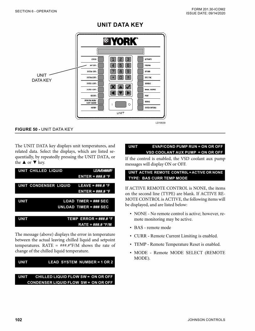
JOHNSON CONTROLS102
FORM 201.30-ICOM2ISSUE DATE: 09/14/2020SECTION 6 - OPERATION
UNIT DATA KEY
LD19539
UNITDATA KEY
FIGURE 50 - UNIT DATA KEY
The UNIT DATA key displays unit temperatures, and related data. Select the displays, which are listed se-quentially, by repeatedly pressing the UNIT DATA, or the or key.
UNIT CHILLED LIQUID LEAVE = ###.# °F ENTER = ###.# °F
UNIT CONDENSER LIQUID LEAVE = ###.# °F ENTER = ###.# °F
UNIT LOAD TIMER = ### SEC UNLOAD TIMER = ### SEC
UNIT TEMP ERROR = ###.# °F RATE = ###.# °F/M
The message (above) displays the error in temperature between the actual leaving chilled liquid and setpoint temperatures. RATE = ###.#°F/M shows the rate of change of the chilled liquid temperature.
UNIT LEAD SYSTEM NUMBER = 1 OR 2
UNIT CHILLED LIQUID FLOW SW = ON OR OFF CONDENSER LIQUID FLOW SW = ON OR OFF
UNIT EVAP/COND PUMP RUN = ON OR OFF VSD COOLANT AUX PUMP = ON OR OFF
If the control is enabled, the VSD coolant aux pump messages will display ON or OFF.
UNIT ACTIVE REMOTE CONTR0L = ACTIVE OR NONETYPE: BAS CURR TEMP MODE
If ACTIVE REMOTE CONTROL is NONE, the items on the second line (TYPE) are blank. If ACTIVE RE-MOTE CONTROL is ACTIVE, the following items will be displayed, and are listed below:
• NONE - No remote control is active; however, re-mote monitoring may be active.
• BAS - remote mode
• CURR - Remote Current Limiting is enabled.
• TEMP - Remote Temperature Reset is enabled.
• MODE - Remote MODE SELECT (REMOTE MODE).
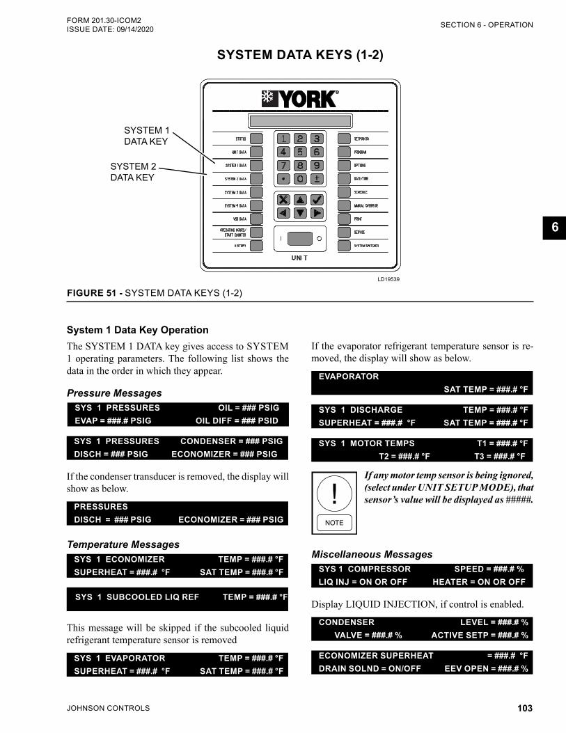
JOHNSON CONTROLS 103
SECTION 6 - OPERATIONFORM 201.30-ICOM2 ISSUE DATE: 09/14/2020
6
System 1 Data Key OperationThe SYSTEM 1 DATA key gives access to SYSTEM 1 operating parameters. The following list shows the data in the order in which they appear.
Pressure Messages
SYS 1 PRESSURES OIL = ### PSIGEVAP = ###.# PSIG OIL DIFF = ### PSID
SYS 1 PRESSURES CONDENSER = ### PSIGDISCH = ### PSIG ECONOMIZER = ### PSIG
If the condenser transducer is removed, the display will show as below.
PRESSURES DISCH = ### PSIG ECONOMIZER = ### PSIG
Temperature MessagesSYS 1 ECONOMIZER TEMP = ###.# °FSUPERHEAT = ###.# °F SAT TEMP = ###.# °F
SYS 1 SUBCOOLED LIQ REF TEMP = ###.# °F
This message will be skipped if the subcooled liquid refrigerant temperature sensor is removed
SYS 1 EVAPORATOR TEMP = ###.# °FSUPERHEAT = ###.# °F SAT TEMP = ###.# °F
SYSTEM DATA KEYS (1-2)
LD19539
FIGURE 51 - SYSTEM DATA KEYS (1-2)
SYSTEM 1 DATA KEY
SYSTEM 2 DATA KEY
If the evaporator refrigerant temperature sensor is re-moved, the display will show as below.
EVAPORATOR SAT TEMP = ###.# °F
SYS 1 DISCHARGE TEMP = ###.# °FSUPERHEAT = ###.# °F SAT TEMP = ###.# °F
SYS 1 MOTOR TEMPS T1 = ###.# °F T2 = ###.# °F T3 = ###.# °F
If any motor temp sensor is being ignored, (select under UNIT SETUP MODE), that sensor’s value will be displayed as #####.
Miscellaneous MessagesSYS 1 COMPRESSOR SPEED = ###.# % LIQ INJ = ON OR OFF HEATER = ON OR OFF
Display LIQUID INJECTION, if control is enabled.
CONDENSER LEVEL = ###.# % VALVE = ###.# % ACTIVE SETP = ###.# %
ECONOMIZER SUPERHEAT = ###.# °FDRAIN SOLND = ON/OFF EEV OPEN = ###.# %
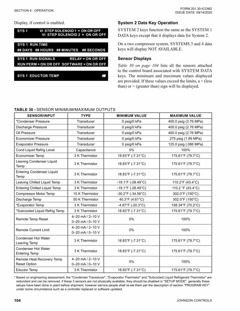
JOHNSON CONTROLS104
FORM 201.30-ICOM2ISSUE DATE: 09/14/2020SECTION 6 - OPERATION
Display, if control is enabled.
SYS 1 VI STEP SOLENOID 1 = ON OR OFF VI STEP SOLENOID 2 = ON OR OFF
SYS 1 RUN TIME## DAYS ## HOURS ## MINUTES ## SECONDS
SYS 1 RUN SIGNALS RELAY = ON OR OFFRUN PERM = ON OR OFF SOFTWARE = ON OR OFF
SYS 1 EDUCTOR TEMP = ###.# °F
TABLE 30 - SENSOR MINIMUM/MAXIMUM OUTPUTSSENSOR/INPUT TYPE MINIMUM VALUE MAXIMUM VALUE
*Condenser Pressure Transducer 0 psig/0 kPa 400.0 psig (2.76 MPa)Discharge Pressure Transducer 0 psig/0 kPa 400.0 psig (2.76 MPa)Oil Pressure Transducer 0 psig/0 kPa 400.0 psig (2.76 MPa)Economizer Pressure Transducer 0 psig/0 kPa 275 psig (1.89 MPa)Evaporator Pressure Transducer 0 psig/0 kPa 125.0 psig (.086 MPa)Cond Liquid Refrig Level Capacitance 0% 100%Economizer Temp 3 K Thermistor 18.83°F (-7.31°C) 175.61°F (79.7°C)Leaving Condenser Liquid Temp 3 K Thermistor 18.83°F (-7.31°C) 175.61°F (79.7°C)
Entering Condenser Liquid Temp 3 K Thermistor 18.83°F (-7.31°C) 175.61°F (79.7°C)
Leaving Chilled Liquid Temp 3 K Thermistor -19.1°F (-28.49°C) 110.2°F (43.4°C)Entering Chilled Liquid Temp 3 K Thermistor -19.1°F (-28.49°C) 110.2 °F (43.4°C)Compressor Motor Temp 10 K Thermistor -30.2°F (-34.56°C) 302.0°F (150°C)Discharge Temp 50 K Thermistor 40.3°F (4.61°C) 302.0°F (150°C)*Evaporator Temp 3 K Thermistor -4.87°F (-20.3°C) 158.34°F (70.2°C)*Subcooled Liquid Refrig Temp 3 K Thermistor 18.83°F (-7.31°C) 175.61°F (79.7°C)
Remote Temp Reset4–20 mA / 2–10 V0–20 mA / 0–10 V
0% 100%
Remote Current Limit4–20 mA / 2–10 V0–20 mA / 0–10 V
0% 100%
Condenser Hot Water Leaving Temp 3 K Thermistor 18.83°F (-7.31°C) 175.61°F (79.7°C)
Condenser Hot Water Entering Temp 3 K Thermistor 18.83°F (-7.31°C) 175.61°F (79.7°C)
Remote Heat Recovery Temp Reset Option
4–20 mA / 2–10 V0–20 mA / 0–10 V
0% 100%
Eductor Temp 3 K Thermistor 18.83°F (-7.31°C) 175.61°F (79.7°C)
* Based on engineering assessment, the "Condenser Transducer", "Evaporator Thermistor" and "Subcooled Liquid Refrigerant Thermistor" are redundant and can be removed. if these 3 sensors are not physically available, they should be disabled in "SETUP MODE", generally these setups have been done in plant before shipment, however service people shall re-set them per the description of section "PROGRAM KEY" under some circumstance such as a controller replaced or software updated.
System 2 Data Key OperationSYSTEM 2 keys function the same as the SYSTEM 1 DATA keys except that it displays data for System 2.
On a two compressor system, SYSTEMS 3 and 4 data keys will display NOT AVAILABLE.
Sensor DisplaysTable 30 on page 104 lists all the sensors attached to the control board associated with SYSTEM DATA keys. The minimum and maximum values displayed are provided. If these values exceed the limits, a < (less than) or > (greater than) sign will be displayed.
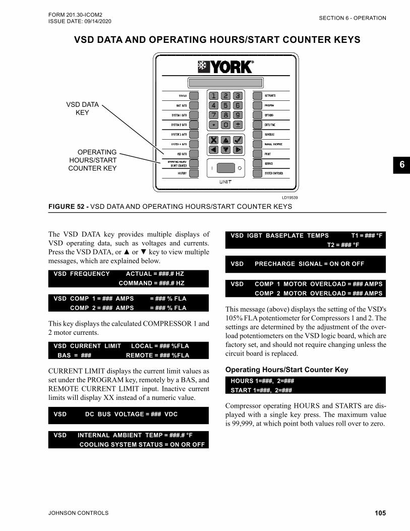
JOHNSON CONTROLS 105
SECTION 6 - OPERATIONFORM 201.30-ICOM2 ISSUE DATE: 09/14/2020
6
VSD DATA AND OPERATING HOURS/START COUNTER KEYS
LD19539
FIGURE 52 - VSD DATA AND OPERATING HOURS/START COUNTER KEYS
VSD DATAKEY
OPERATING HOURS/START COUNTER KEY
The VSD DATA key provides multiple displays of VSD operating data, such as voltages and currents. Press the VSD DATA, or or key to view multiple messages, which are explained below.
VSD FREQUENCY ACTUAL = ###.# HZ COMMAND = ###.# HZ
VSD COMP 1 = ### AMPS = ### % FLA COMP 2 = ### AMPS = ### % FLA
This key displays the calculated COMPRESSOR 1 and 2 motor currents.
VSD CURRENT LIMIT LOCAL = ### %FLA BAS = ### REMOTE = ### %FLA
CURRENT LIMIT displays the current limit values as set under the PROGRAM key, remotely by a BAS, and REMOTE CURRENT LIMIT input. Inactive current limits will display XX instead of a numeric value.
VSD DC BUS VOLTAGE = ### VDC
VSD INTERNAL AMBIENT TEMP = ###.# °F COOLING SYSTEM STATUS = ON OR OFF
VSD IGBT BASEPLATE TEMPS T1 = ### °F T2 = ### °F
VSD PRECHARGE SIGNAL = ON OR OFF
VSD COMP 1 MOTOR OVERLOAD = ### AMPS COMP 2 MOTOR OVERLOAD = ### AMPS
This message (above) displays the setting of the VSD's 105% FLA potentiometer for Compressors 1 and 2. The settings are determined by the adjustment of the over-load potentiometers on the VSD logic board, which are factory set, and should not require changing unless the circuit board is replaced.
Operating Hours/Start Counter KeyHOURS 1=###, 2=###START 1=###, 2=###
Compressor operating HOURS and STARTS are dis-played with a single key press. The maximum value is 99,999, at which point both values roll over to zero.
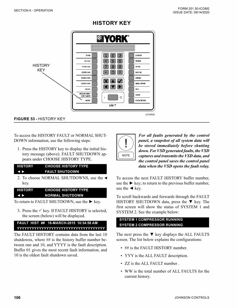
JOHNSON CONTROLS106
FORM 201.30-ICOM2ISSUE DATE: 09/14/2020SECTION 6 - OPERATION
HISTORY KEY
LD19539
HISTORYKEY
FIGURE 53 - HISTORY KEY
For all faults generated by the control panel, a snapshot of all system data will be stored immediately before shutting down. For VSD generated faults, the VSD captures and transmits the VSD data, and the control panel saves the control panel data when the VSD opens the fault relay.
To access the next FAULT HISTORY buffer number, use the key; to return to the previous buffer number, use the key.
To scroll backwards and forwards through the FAULT HISTORY SHUTDOWN data, press the key. The first screen will show the status of SYSTEM 1 and SYSTEM 2. See the example below:
SYSTEM 1 COMPRESSOR RUNNINGSYSTEM 2 COMPRESSOR RUNNING
The next press the key displays the ALL FAULTS screen. The list below explains the configurations:
• ## is the FAULT HISTORY number.
• YYY is the ALL FAULT description.
• ZZ is the ALL FAULT number .
• WW is the total number of ALL FAULTS for the current history.
To access the HISTORY FAULT or NORMAL SHUT-DOWN information, use the following steps:
1. Press the HISTORY key to display the initial his-tory message (above). FAULT SHUTDOWN ap-pears under CHOOSE HISTORY TYPE.
HISTORY CHOOSE HISTORY TYPE FAULT SHUTDOWN
2. To choose NORMAL SHUTDOWNS, use the key.
HISTORY CHOOSE HISTORY TYPE NORMAL SHUTDOWN
To return to FAULT SHUTDOWN, use the key.
3. Press the key. If FAULT HISTORY is selected, the screen (below) will be displayed.
FAULT HIST ## 18-MARCH-2015 10:34:58 AMYYYYYYYYYYYYYYYYYYYYYYYYYYYYYYYYYYYY
The FAULT HISTORY contains data from the last 10 shutdowns, where ## is the history buffer number be-tween one and 10, and YYYY is the fault description. Buffer 01 gives the most recent fault information, and 10 is the oldest fault shutdown saved.
JOHNSON CONTROLS 107
SECTION 6 - OPERATIONFORM 201.30-ICOM2 ISSUE DATE: 09/14/2020
6
If there are no ALL FAULTS for the current history, the following message will be displayed for the ALL FAULTS screen.
FAULT HIST ## ALL FAULTS NONE
Use the keys to scroll forwards and backwards through the FAULT HISTORY SHUTDOWN data within each section, i.e. UNIT.
• UNIT on page 102
• Chilled Liquid
• Compressor 1 and 2, etc.
• SYSTEM 1 OR 2 on page 103
• Oil Pressure
• Condenser Pressure Message, etc.
• VSD on page 105
• Frequency
• VSD Current
• SETPOINTS on page 108
• Local Cooling Setpoint
• Local Cooling Range, etc.
• OPERATING HOURS/START COUNTER on page 105
• Day of Week
• Day of Month, etc.
• OPTIONS on page 112
• Display Language
• Liquid Type, etc.
• PROGRAM on page 110
• Chilled Liquid Leaving Temp Cutout
• Motor Current Limit, etc.
Refer to the specific section of this manual for a com-plete list of messages.
NORM HIST ## 12-MARCH-2015 10:34:58 AMYYYYYYYYYYYYYYYYYYYYYYYYYYYYYYYYYYYYY
If NORMAL SHUTDOWNS is selected, the NORM HIST ## will be displayed, where ## is the normal shut-down number. YYYY explains the reason for the shut-down. The normal shutdown history contains limited data from the last 20 normal (non-fault) shutdowns.
From the initial NORMAL HISTORY SHUTDOWN screen, the key scrolls to the initial screen of the next buffer, and the key to the initial screen of the last buffer. Buffer 01 is the most recent fault shutdown, and 20 is the oldest fault shutdown saved.
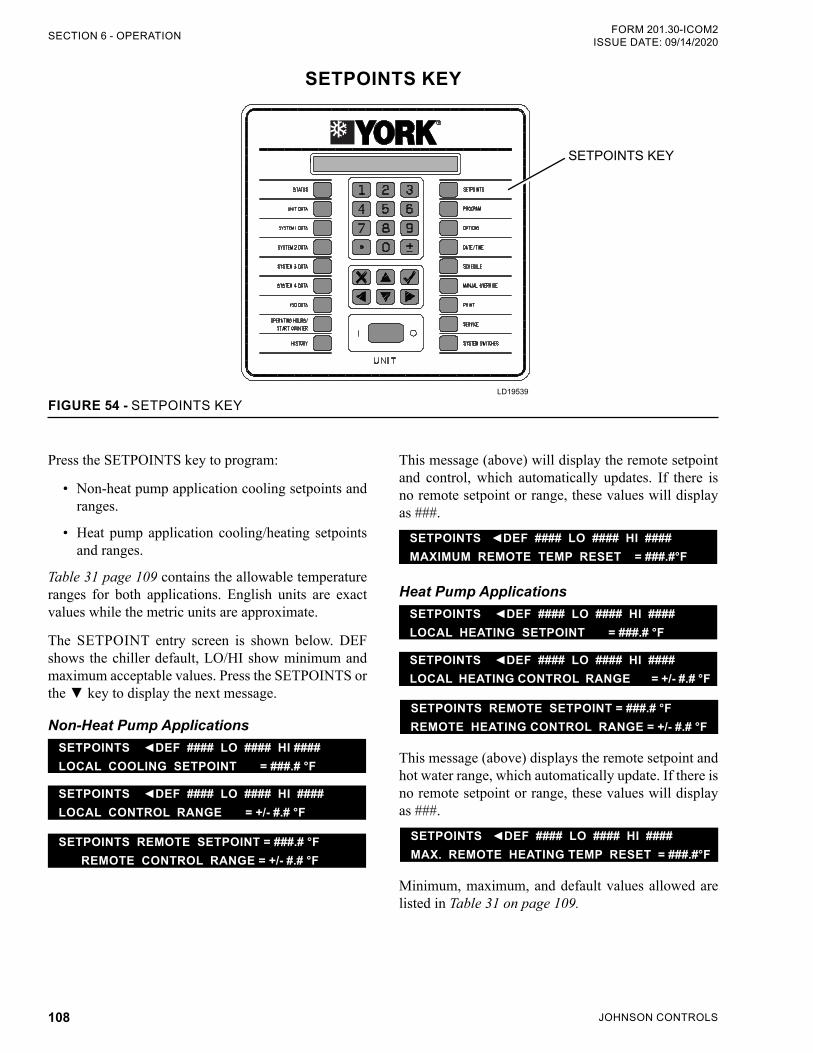
JOHNSON CONTROLS108
FORM 201.30-ICOM2ISSUE DATE: 09/14/2020SECTION 6 - OPERATION
SETPOINTS KEY
FIGURE 54 - SETPOINTS KEYLD19539
SETPOINTS KEY
This message (above) will display the remote setpoint and control, which automatically updates. If there is no remote setpoint or range, these values will display as ###.
SETPOINTS DEF #### LO #### HI ####MAXIMUM REMOTE TEMP RESET = ###.#°F
Heat Pump ApplicationsSETPOINTS DEF #### LO #### HI ####LOCAL HEATING SETPOINT = ###.# °F
SETPOINTS DEF #### LO #### HI ####LOCAL HEATING CONTROL RANGE = +/- #.# °F
SETPOINTS REMOTE SETPOINT = ###.# °F REMOTE HEATING CONTROL RANGE = +/- #.# °F
This message (above) displays the remote setpoint and hot water range, which automatically update. If there is no remote setpoint or range, these values will display as ###.
SETPOINTS DEF #### LO #### HI ####MAX. REMOTE HEATING TEMP RESET = ###.#°F
Minimum, maximum, and default values allowed are listed in Table 31 on page 109.
Press the SETPOINTS key to program:
• Non-heat pump application cooling setpoints and ranges.
• Heat pump application cooling/heating setpoints and ranges.
Table 31 page 109 contains the allowable temperature ranges for both applications. English units are exact values while the metric units are approximate.
The SETPOINT entry screen is shown below. DEF shows the chiller default, LO/HI show minimum and maximum acceptable values. Press the SETPOINTS or the key to display the next message.
Non-Heat Pump ApplicationsSETPOINTS DEF #### LO #### HI ####LOCAL COOLING SETPOINT = ###.# °F
SETPOINTS DEF #### LO #### HI ####LOCAL CONTROL RANGE = +/- #.# °F
SETPOINTS REMOTE SETPOINT = ###.# °F REMOTE CONTROL RANGE = +/- #.# °F
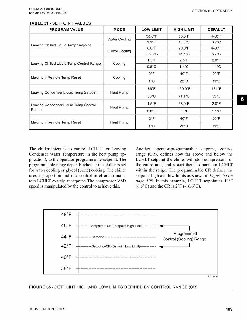
JOHNSON CONTROLS 109
SECTION 6 - OPERATIONFORM 201.30-ICOM2 ISSUE DATE: 09/14/2020
6
TABLE 31 - SETPOINT VALUESPROGRAM VALUE MODE LOW LIMIT HIGH LIMIT DEFAULT
Leaving Chilled Liquid Temp Setpoint Water Cooling
38.0°F 60.0°F 44.0°F3.3°C 15.6°C 6.7°C
Glycol Cooling8.0°F 70.0°F 44.0°F
-13.3°C 15.6°C 6.7°C
Leaving Chilled Liquid Temp Control Range Cooling1.5°F 2.5°F 2.0°F
0.8°C 1.4°C 1.1°C
Maximum Remote Temp Reset Cooling2°F 40°F 20°F
1°C 22°C 11°C
Leaving Condenser Liquid Temp Setpoint Heat Pump86°F 160.0°F 131°F
30°C 71.1°C 55°C
Leaving Condenser Liquid Temp Control Range Heat Pump
1.5°F 38.0°F 2.0°F
0.8°C 3.3°C 1.1°C
Maximum Remote Temp Reset Heat Pump2°F 40°F 20°F
1°C 22°C 11°C
Another operator-programmable setpoint, control range (CR), defines how far above and below the LCHLT setpoint the chiller will stop compressors, or the entire unit, and restart them to maintain LCHLT within the range. The programmable CR defines the setpoint high and low limits as shown in Figure 55 on page 109. In this example, LCHLT setpoint is 44°F (6.6°C) and the CR is 2°F (-16.6°C).
FIGURE 55 - SETPOINT HIGH AND LOW LIMITS DEFINED BY CONTROL RANGE (CR)
48°F -------------------------------------------------- 46°F --------- Setpoint + CR ( Setpoint High Limit) ---------- Programmed
44°F ----------Setpoint --------------------------------- Control (Cooling) Range
42°F ---------- ----------Setpoint – CR (Setpoint Low Limit)
40°F
38°F --------------------------------------------------
--------------------------------------------------
LD16433
The chiller intent is to control LCHLT (or Leaving Condenser Water Temperature in the heat pump ap-plication), to the operator-programmable setpoint. The programmable range depends whether the chiller is set for water cooling or glycol (brine) cooling. The chiller uses a proportion and rate control in effort to main-tain LCHLT exactly at setpoint. The compressor VSD speed is manipulated by the control to achieve this.
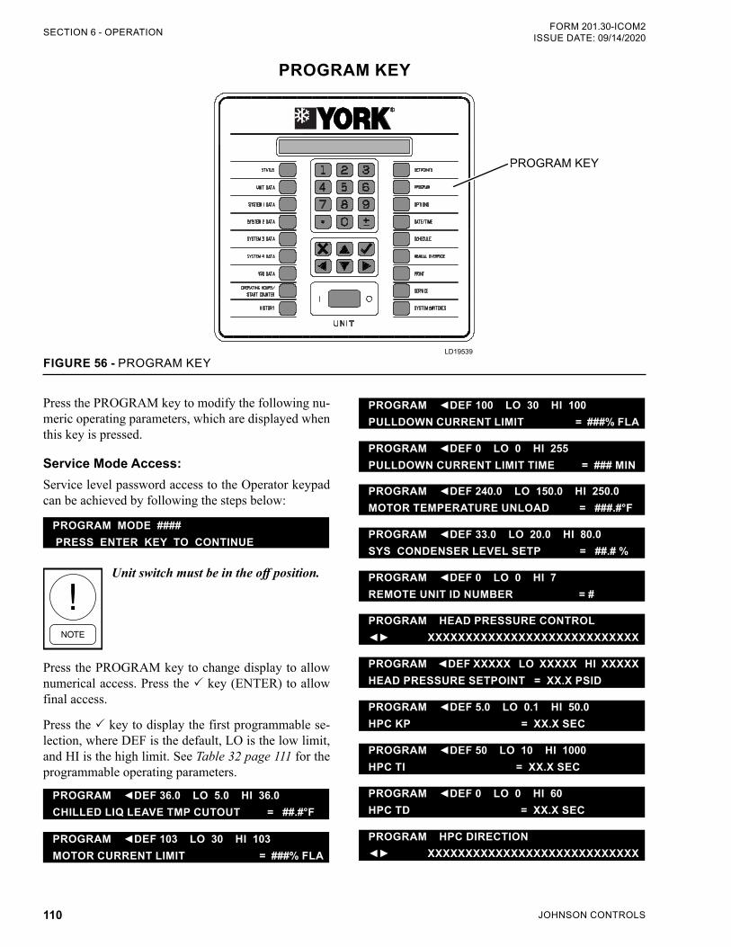
JOHNSON CONTROLS110
FORM 201.30-ICOM2ISSUE DATE: 09/14/2020SECTION 6 - OPERATION
PROGRAM KEY
FIGURE 56 - PROGRAM KEYLD19539
PROGRAM KEY
PROGRAM DEF 100 LO 30 HI 100PULLDOWN CURRENT LIMIT = ###% FLA
PROGRAM DEF 0 LO 0 HI 255PULLDOWN CURRENT LIMIT TIME = ### MIN
PROGRAM DEF 240.0 LO 150.0 HI 250.0MOTOR TEMPERATURE UNLOAD = ###.#°F
PROGRAM DEF 33.0 LO 20.0 HI 80.0SYS CONDENSER LEVEL SETP = ##.# %
PROGRAM DEF 0 LO 0 HI 7REMOTE UNIT ID NUMBER = #
PROGRAM HEAD PRESSURE CONTROL XXXXXXXXXXXXXXXXXXXXXXXXXXXX
PROGRAM DEF XXXXX LO XXXXX HI XXXXXHEAD PRESSURE SETPOINT = XX.X PSID
PROGRAM DEF 5.0 LO 0.1 HI 50.0HPC KP = XX.X SEC
PROGRAM DEF 50 LO 10 HI 1000HPC TI = XX.X SEC
PROGRAM DEF 0 LO 0 HI 60HPC TD = XX.X SEC
PROGRAM HPC DIRECTION XXXXXXXXXXXXXXXXXXXXXXXXXXXX
Press the PROGRAM key to modify the following nu-meric operating parameters, which are displayed when this key is pressed.
Service Mode Access:Service level password access to the Operator keypad can be achieved by following the steps below:
PROGRAM MODE #### PRESS ENTER KEY TO CONTINUE
Unit switch must be in the off position.
Press the PROGRAM key to change display to allow numerical access. Press the key (ENTER) to allow final access.
Press the key to display the first programmable se-lection, where DEF is the default, LO is the low limit, and HI is the high limit. See Table 32 page 111 for the programmable operating parameters.
PROGRAM DEF 36.0 LO 5.0 HI 36.0CHILLED LIQ LEAVE TMP CUTOUT = ##.#°F
PROGRAM DEF 103 LO 30 HI 103MOTOR CURRENT LIMIT = ###% FLA
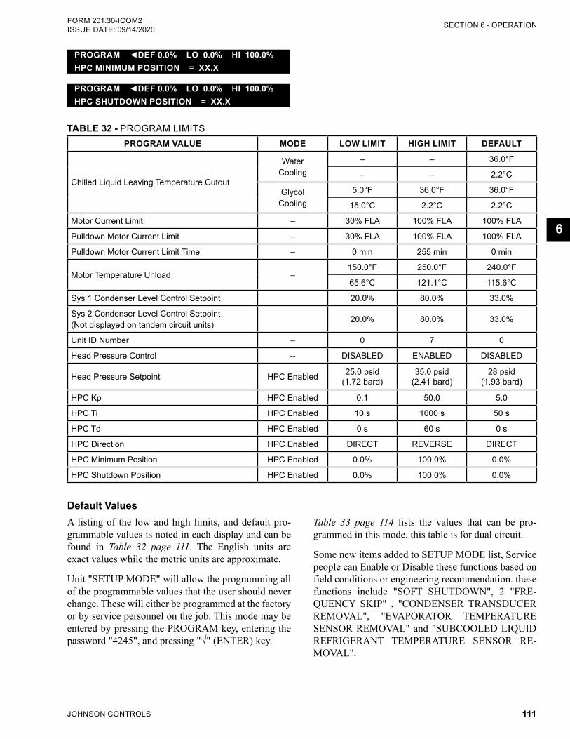
JOHNSON CONTROLS 111
SECTION 6 - OPERATIONFORM 201.30-ICOM2 ISSUE DATE: 09/14/2020
6
PROGRAM DEF 0.0% LO 0.0% HI 100.0%HPC MINIMUM POSITION = XX.X
PROGRAM DEF 0.0% LO 0.0% HI 100.0%HPC SHUTDOWN POSITION = XX.X
TABLE 32 - PROGRAM LIMITSPROGRAM VALUE MODE LOW LIMIT HIGH LIMIT DEFAULT
Chilled Liquid Leaving Temperature Cutout
Water Cooling
– – 36.0°F
– – 2.2°C
Glycol Cooling
5.0°F 36.0°F 36.0°F
15.0°C 2.2°C 2.2°C
Motor Current Limit – 30% FLA 100% FLA 100% FLA
Pulldown Motor Current Limit – 30% FLA 100% FLA 100% FLA
Pulldown Motor Current Limit Time – 0 min 255 min 0 min
Motor Temperature Unload –150.0°F 250.0°F 240.0°F
65.6°C 121.1°C 115.6°C
Sys 1 Condenser Level Control Setpoint 20.0% 80.0% 33.0%
Sys 2 Condenser Level Control Setpoint (Not displayed on tandem circuit units) 20.0% 80.0% 33.0%
Unit ID Number – 0 7 0
Head Pressure Control -- DISABLED ENABLED DISABLED
Head Pressure Setpoint HPC Enabled 25.0 psid (1.72 bard)
35.0 psid (2.41 bard)
28 psid (1.93 bard)
HPC Kp HPC Enabled 0.1 50.0 5.0
HPC Ti HPC Enabled 10 s 1000 s 50 s
HPC Td HPC Enabled 0 s 60 s 0 s
HPC Direction HPC Enabled DIRECT REVERSE DIRECT
HPC Minimum Position HPC Enabled 0.0% 100.0% 0.0%
HPC Shutdown Position HPC Enabled 0.0% 100.0% 0.0%
Table 33 page 114 lists the values that can be pro-grammed in this mode. this table is for dual circuit.
Some new items added to SETUP MODE list, Service people can Enable or Disable these functions based on field conditions or engineering recommendation. these functions include "SOFT SHUTDOWN", 2 "FRE-QUENCY SKIP" , "CONDENSER TRANSDUCER REMOVAL", "EVAPORATOR TEMPERATURE SENSOR REMOVAL" and "SUBCOOLED LIQUID REFRIGERANT TEMPERATURE SENSOR RE-MOVAL".
Default ValuesA listing of the low and high limits, and default pro-grammable values is noted in each display and can be found in Table 32 page 111. The English units are exact values while the metric units are approximate.
Unit "SETUP MODE" will allow the programming all of the programmable values that the user should never change. These will either be programmed at the factory or by service personnel on the job. This mode may be entered by pressing the PROGRAM key, entering the password "4245", and pressing "√" (ENTER) key.
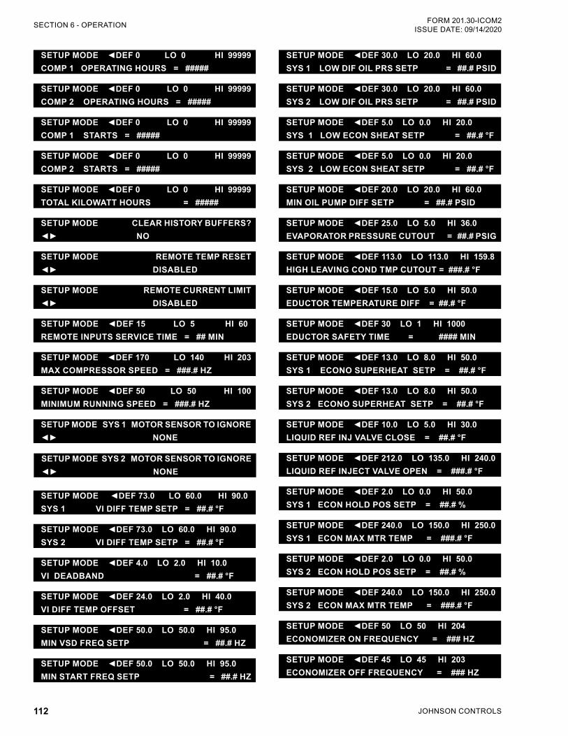
JOHNSON CONTROLS112
FORM 201.30-ICOM2ISSUE DATE: 09/14/2020SECTION 6 - OPERATION
SETUP MODE DEF 0 LO 0 HI 99999COMP 1 OPERATING HOURS = #####
SETUP MODE DEF 0 LO 0 HI 99999COMP 2 OPERATING HOURS = #####
SETUP MODE DEF 0 LO 0 HI 99999COMP 1 STARTS = #####
SETUP MODE DEF 0 LO 0 HI 99999COMP 2 STARTS = #####
SETUP MODE DEF 0 LO 0 HI 99999TOTAL KILOWATT HOURS = #####
SETUP MODE CLEAR HISTORY BUFFERS? NO
SETUP MODE REMOTE TEMP RESET DISABLED
SETUP MODE REMOTE CURRENT LIMIT DISABLED
SETUP MODE DEF 15 LO 5 HI 60REMOTE INPUTS SERVICE TIME = ## MIN
SETUP MODE DEF 170 LO 140 HI 203MAX COMPRESSOR SPEED = ###.# HZ
SETUP MODE DEF 50 LO 50 HI 100MINIMUM RUNNING SPEED = ###.# HZ
SETUP MODE SYS 1 MOTOR SENSOR TO IGNORE NONE
SETUP MODE SYS 2 MOTOR SENSOR TO IGNORE NONE
SETUP MODE DEF 73.0 LO 60.0 HI 90.0SYS 1 VI DIFF TEMP SETP = ##.# °F
SETUP MODE DEF 73.0 LO 60.0 HI 90.0SYS 2 VI DIFF TEMP SETP = ##.# °F
SETUP MODE DEF 4.0 LO 2.0 HI 10.0VI DEADBAND = ##.# °F
SETUP MODE DEF 24.0 LO 2.0 HI 40.0VI DIFF TEMP OFFSET = ##.# °F
SETUP MODE DEF 50.0 LO 50.0 HI 95.0MIN VSD FREQ SETP = ##.# HZ
SETUP MODE DEF 50.0 LO 50.0 HI 95.0MIN START FREQ SETP = ##.# HZ
SETUP MODE DEF 30.0 LO 20.0 HI 60.0SYS 1 LOW DIF OIL PRS SETP = ##.# PSID
SETUP MODE DEF 30.0 LO 20.0 HI 60.0SYS 2 LOW DIF OIL PRS SETP = ##.# PSID
SETUP MODE DEF 5.0 LO 0.0 HI 20.0SYS 1 LOW ECON SHEAT SETP = ##.# °F
SETUP MODE DEF 5.0 LO 0.0 HI 20.0SYS 2 LOW ECON SHEAT SETP = ##.# °F
SETUP MODE DEF 20.0 LO 20.0 HI 60.0MIN OIL PUMP DIFF SETP = ##.# PSID
SETUP MODE DEF 25.0 LO 5.0 HI 36.0EVAPORATOR PRESSURE CUTOUT = ##.# PSIG
SETUP MODE DEF 113.0 LO 113.0 HI 159.8HIGH LEAVING COND TMP CUTOUT = ###.# °F
SETUP MODE DEF 15.0 LO 5.0 HI 50.0EDUCTOR TEMPERATURE DIFF = ##.# °F
SETUP MODE DEF 30 LO 1 HI 1000EDUCTOR SAFETY TIME = #### MIN
SETUP MODE DEF 13.0 LO 8.0 HI 50.0SYS 1 ECONO SUPERHEAT SETP = ##.# °F
SETUP MODE DEF 13.0 LO 8.0 HI 50.0SYS 2 ECONO SUPERHEAT SETP = ##.# °F
SETUP MODE DEF 10.0 LO 5.0 HI 30.0 LIQUID REF INJ VALVE CLOSE = ##.# °F
SETUP MODE DEF 212.0 LO 135.0 HI 240.0LIQUID REF INJECT VALVE OPEN = ###.# °F
SETUP MODE DEF 2.0 LO 0.0 HI 50.0SYS 1 ECON HOLD POS SETP = ##.# %
SETUP MODE DEF 240.0 LO 150.0 HI 250.0SYS 1 ECON MAX MTR TEMP = ###.# °F
SETUP MODE DEF 2.0 LO 0.0 HI 50.0SYS 2 ECON HOLD POS SETP = ##.# %
SETUP MODE DEF 240.0 LO 150.0 HI 250.0SYS 2 ECON MAX MTR TEMP = ###.# °F
SETUP MODE DEF 50 LO 50 HI 204ECONOMIZER ON FREQUENCY = ### HZ
SETUP MODE DEF 45 LO 45 HI 203ECONOMIZER OFF FREQUENCY = ### HZ
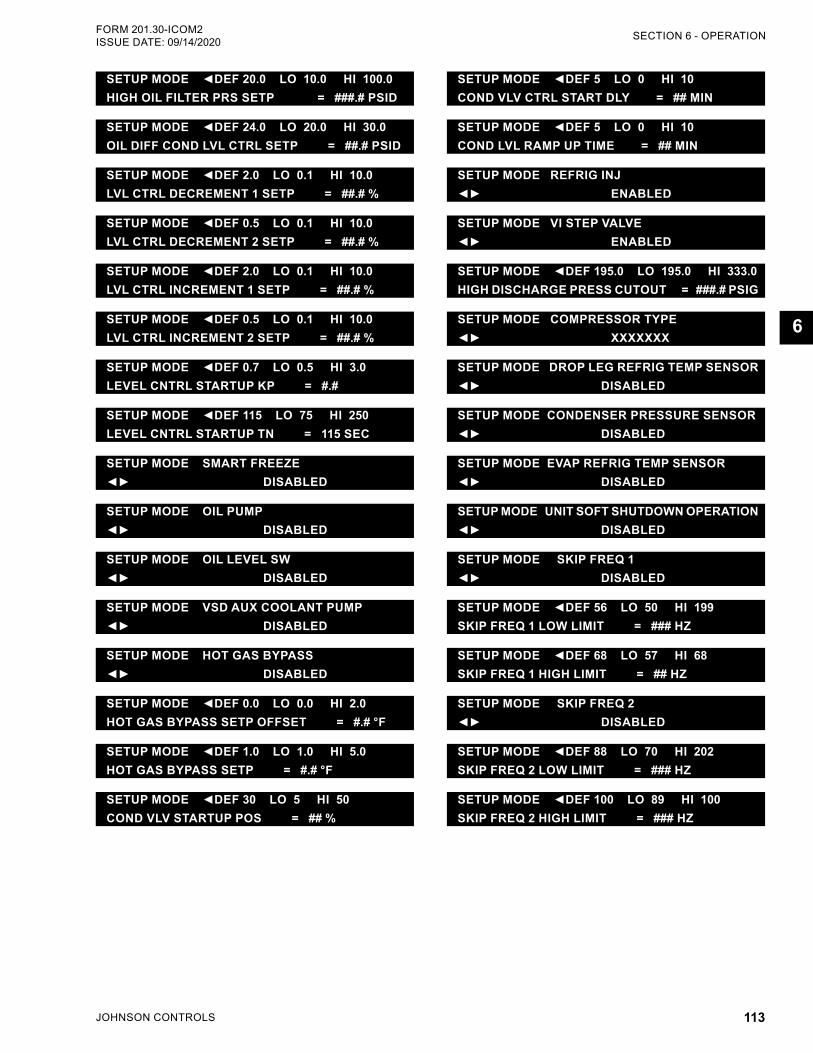
JOHNSON CONTROLS 113
SECTION 6 - OPERATIONFORM 201.30-ICOM2 ISSUE DATE: 09/14/2020
6
SETUP MODE DEF 20.0 LO 10.0 HI 100.0HIGH OIL FILTER PRS SETP = ###.# PSID
SETUP MODE DEF 24.0 LO 20.0 HI 30.0OIL DIFF COND LVL CTRL SETP = ##.# PSID
SETUP MODE DEF 2.0 LO 0.1 HI 10.0LVL CTRL DECREMENT 1 SETP = ##.# %
SETUP MODE DEF 0.5 LO 0.1 HI 10.0LVL CTRL DECREMENT 2 SETP = ##.# %
SETUP MODE DEF 2.0 LO 0.1 HI 10.0LVL CTRL INCREMENT 1 SETP = ##.# %
SETUP MODE DEF 0.5 LO 0.1 HI 10.0LVL CTRL INCREMENT 2 SETP = ##.# %
SETUP MODE DEF 0.7 LO 0.5 HI 3.0LEVEL CNTRL STARTUP KP = #.#
SETUP MODE DEF 115 LO 75 HI 250LEVEL CNTRL STARTUP TN = 115 SEC
SETUP MODE SMART FREEZE DISABLED
SETUP MODE OIL PUMP DISABLED
SETUP MODE OIL LEVEL SW DISABLED
SETUP MODE VSD AUX COOLANT PUMP DISABLED
SETUP MODE HOT GAS BYPASS DISABLED
SETUP MODE DEF 0.0 LO 0.0 HI 2.0HOT GAS BYPASS SETP OFFSET = #.# °F
SETUP MODE DEF 1.0 LO 1.0 HI 5.0HOT GAS BYPASS SETP = #.# °F
SETUP MODE DEF 30 LO 5 HI 50COND VLV STARTUP POS = ## %
SETUP MODE DEF 5 LO 0 HI 10COND VLV CTRL START DLY = ## MIN
SETUP MODE DEF 5 LO 0 HI 10COND LVL RAMP UP TIME = ## MIN
SETUP MODE REFRIG INJ ENABLED
SETUP MODE VI STEP VALVE ENABLED
SETUP MODE DEF 195.0 LO 195.0 HI 333.0HIGH DISCHARGE PRESS CUTOUT = ###.# PSIG
SETUP MODE COMPRESSOR TYPE XXXXXXX
SETUP MODE DROP LEG REFRIG TEMP SENSOR DISABLED
SETUP MODE CONDENSER PRESSURE SENSOR DISABLED
SETUP MODE EVAP REFRIG TEMP SENSOR DISABLED
SETUP MODE UNIT SOFT SHUTDOWN OPERATION DISABLED
SETUP MODE SKIP FREQ 1 DISABLED
SETUP MODE DEF 56 LO 50 HI 199SKIP FREQ 1 LOW LIMIT = ### HZ
SETUP MODE DEF 68 LO 57 HI 68SKIP FREQ 1 HIGH LIMIT = ## HZ
SETUP MODE SKIP FREQ 2 DISABLED
SETUP MODE DEF 88 LO 70 HI 202SKIP FREQ 2 LOW LIMIT = ### HZ
SETUP MODE DEF 100 LO 89 HI 100SKIP FREQ 2 HIGH LIMIT = ### HZ
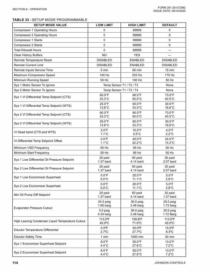
JOHNSON CONTROLS114
FORM 201.30-ICOM2ISSUE DATE: 09/14/2020SECTION 6 - OPERATION
TABLE 33 - SETUP MODE PROGRAMMABLESETUP MODE VALUE LOW LIMIT HIGH LIMIT DEFAULT
Compressor 1 Operating Hours 0 99999 0Compressor 2 Operating Hours 0 99999 0Compressor 1 Starts 0 99999 0Compressor 2 Starts 0 99999 0Total Kilowatt Hours 0 99999 —Clear History Buffers NO YES —Remote Temperature Reset DISABLED ENABLED DISABLEDRemote Current Limit DISABLED ENABLED DISABLEDRemote Inputs Service Time 5 min 60 min 15 minMaximum Compressor Speed 140 Hz 203 Hz 170 HzMinimum Running Speed 50 Hz 100 Hz 50 HzSys 1 Motor Sensor To Ignore Temp Sensor T1 / T2 / T3 NoneSys 2 Motor Sensor To Ignore Temp Sensor T1 / T2 / T4 None
Sys 1 VI Differential Temp Setpoint (CTS) 60.0°F 33.3°C
90.0°F 50.0°C
73.0°F 40.5°C
Sys 1 VI Differential Temp Setpoint (WTS) 25.0°F 13.8°C
60.0°F 33.3°C
30.0°F 16.6°C
Sys 2 VI Differential Temp Setpoint (CTS) 60.0°F 33.3°C
90.0°F 50.0°C
73.0°F 40.5°C
Sys 2 VI Differential Temp Setpoint (WTS) 25.0°F 13.8°C
60.0°F 33.3°C
30.0°F 16.6°C
VI Dead band (CTS and WTS) 2.0°F 1.1°C
10.0°F 5.5°C
4.0°F 2.2°C
VI Differential Temp Setpoint Offset 2.0°F 1.1°C
40.0°F 22.2°C
24.0°F 13.3°C
Minimum VSD Frequency 50 Hz 95 Hz 50 HzMinimum Start Frequency 50 Hz 95 Hz 50 Hz
Sys 1 Low Differential Oil Pressure Setpoint 20 psid 1.37 bard
60 psid 4.14 bard
30 psid 2.07 bard
Sys 2 Low Differential Oil Pressure Setpoint 20 psid 1.37 bard
60 psid 4.14 bard
30 psid 2.07 bard
Sys 1 Low Economizer Superheat 0.0°F 0.0°C
20.0°F 11.1°C
5.0°F 2.8°C
Sys 2 Low Economizer Superheat 0.0°F 0.0°C
20.0°F 11.1°C
5.0°F 2.8°C
Min Oil Pump Diff Setpoint 20 psid 1.37 bard
60 psid 4.14 bard
20 psid 1.37 bard
Evaporator Pressure Cutout
24.0 psig 1.65 barg
36.0 psig 2.48 barg
25.0 psig 1.72 barg
5.0 psig 0.34 barg
36.0 psig 2.48 barg
25.0 psig 1.72 Barg
High Leaving Condenser Liquid Temperature Cutout 113.0ºF 45.0ºC
159.8ºF 71.0ºC
113.0ºF 45.0ºC
Eductor Temperature Differential 5.0ºF 2.7ºC
50.0ºF 27.7ºC
15.0ºF 8.3ºC
Eductor Safety Time 1 min 1000 min 30 min
Sys 1 Economizer Superheat Setpoint 8.0°F 4.4°C
50.0°F 27.8°C
13.0°F 7.2°C
Sys 2 Economizer Superheat Setpoint 8.0°F 4.4°C
50.0°F 27.8°C
13.0°F 7.2°C
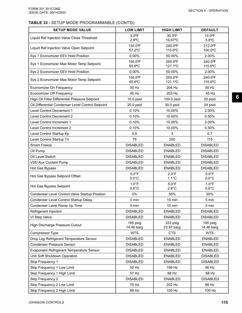
JOHNSON CONTROLS 115
SECTION 6 - OPERATIONFORM 201.30-ICOM2 ISSUE DATE: 09/14/2020
6
SETUP MODE VALUE LOW LIMIT HIGH LIMIT DEFAULT
Liquid Ref Injection Valve Close Threshold 5.0ºF 2.8ºC
30.0ºF 16.67ºC
10.0ºF 5.6ºC
Liquid Ref Injection Valve Open Setpoint 135.0ºF 57.2ºC
240.0ºF 115.6ºC
212.0ºF 100.0ºC
Sys 1 Economizer EEV Hold Position 0.00% 50.00% 2.00%
Sys 1 Economizer Max Motor Temp Setpoint 150.0ºF 65.6ºC
250.0ºF 121.1ºC
240.0ºF 115.6ºC
Sys 2 Economizer EEV Hold Position 0.00% 50.00% 2.00%
Sys 2 Economizer Max Motor Temp Setpoint 150.0ºF 65.6ºC
250.0ºF 121.1ºC
240.0ºF 115.6ºC
Economizer On Frequency 50 Hz 204 Hz 50 HzEconomizer Off Frequency 45 Hz 203 Hz 45 HzHigh Oil Filter Differential Pressure Setpoint 10.0 psid 100.0 psid 20 psidOil Differential Condenser Level Control Setpoint 20.0 psid 30.0 psid 24 psidLevel Control Decrement 1 0.10% 10.00% 2.00%Level Control Decrement 2 0.10% 10.00% 0.50%Level Control Increment 1 0.10% 10.00% 2.00%Level Control Increment 2 0.10% 10.00% 0.50%Level Control Startup Kp 0.5 3 0.7Level Control Startup Tn 75 250 115Smart Freeze DISABLED ENABLED DISABLEDOil Pump DISABLED ENABLED DISABLEDOil Level Switch DISABLED ENABLED DISABLEDVSD Aux Coolant Pump DISABLED ENABLED DISABLEDHot Gas Bypass DISABLED ENABLED DISABLED
Hot Gas Bypass Setpoint Offset 0.0°F 0.0°C
2.0°F 1.1°C
0.0°F 0.0°C
Hot Gas Bypass Setpoint 1.0°F 0.6°C
5.0°F 2.8°C
1.0°F 0.6°C
Condenser Level Control Valve Startup Position 5% 50% 30%Condenser Level Control Startup Delay 0 min 10 min 5 minCondenser Level Ramp Up Time 0 min 10 min 5 minRefrigerant Injection DISABLED ENABLED DISABLEDVI Step Valve DISABLED ENABLED DISABLED
High Discharge Pressure Cutout 195 psig 14.46 barg
333 psig 23.97 barg
195 psig 14.46 barg
Compressor Type WTS CTS WTSDrop Leg Refrigerant Temperature Sensor DISABLED ENABLED ENABLEDCondenser Pressure Sensor DISABLED ENABLED ENABLEDEvaporator Refrigerant Temperature Sensor DISABLED ENABLED ENABLEDUnit Soft Shutdown Operation DISABLED ENABLED DISABLEDSkip Frequency 1 DISABLED ENABLED DISABLEDSkip Frequency 1 Low Limit 50 Hz 199 Hz 56 HzSkip Frequency 1 High Limit 57 Hz 68 Hz 68 HzSkip Frequency 2 DISABLED ENABLED DISABLEDSkip Frequency 2 Low Limit 70 Hz 202 Hz 88 HzSkip Frequency 2 High Limit 89 Hz 100 Hz 100 Hz
TABLE 33 - SETUP MODE PROGRAMMABLE (CONT'D)
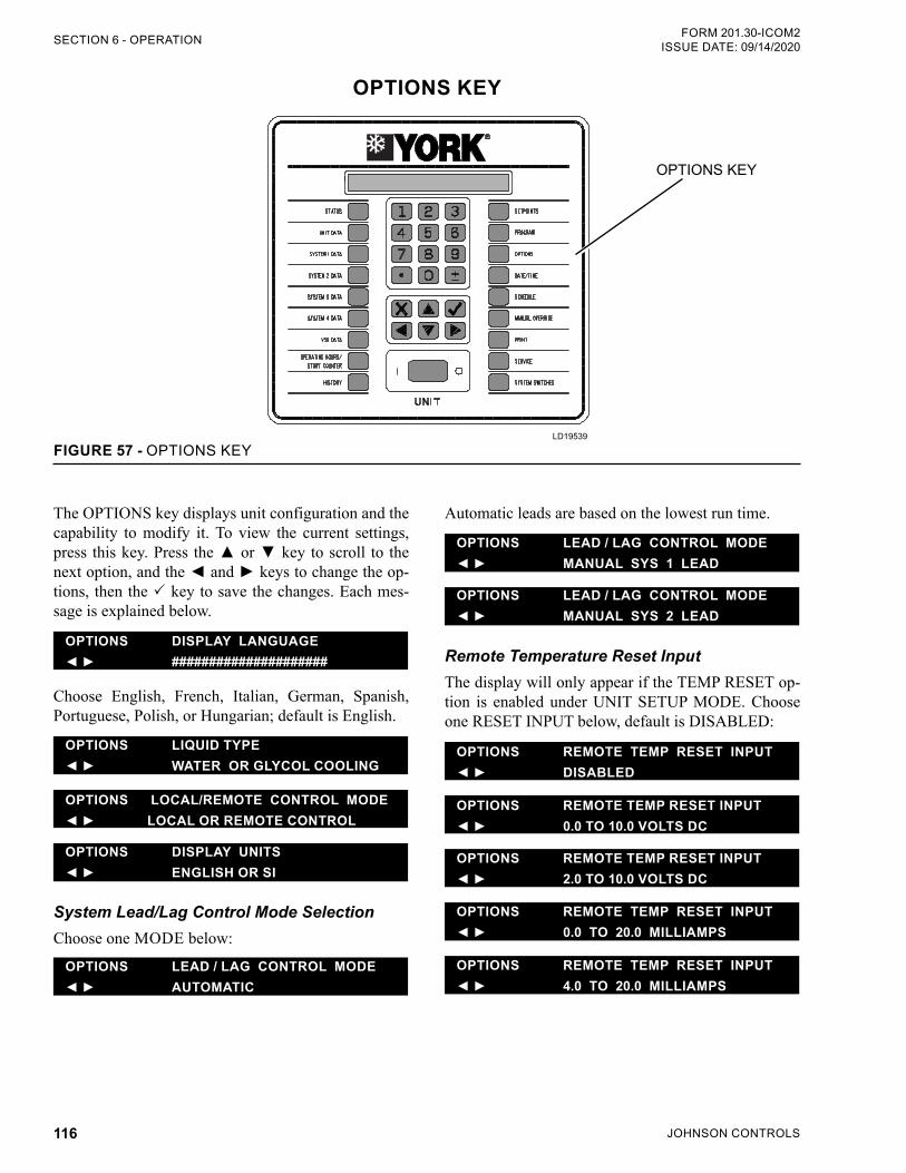
JOHNSON CONTROLS116
FORM 201.30-ICOM2ISSUE DATE: 09/14/2020SECTION 6 - OPERATION
OPTIONS KEY
FIGURE 57 - OPTIONS KEYLD19539
OPTIONS KEY
The OPTIONS key displays unit configuration and the capability to modify it. To view the current settings, press this key. Press the or key to scroll to the next option, and the and keys to change the op-tions, then the key to save the changes. Each mes-sage is explained below.
OPTIONS DISPLAY LANGUAGE #####################
Choose English, French, Italian, German, Spanish, Portuguese, Polish, or Hungarian; default is English.
OPTIONS LIQUID TYPE WATER OR GLYCOL COOLING
OPTIONS LOCAL/REMOTE CONTROL MODE LOCAL OR REMOTE CONTROL
OPTIONS DISPLAY UNITS ENGLISH OR SI
System Lead/Lag Control Mode SelectionChoose one MODE below:
OPTIONS LEAD / LAG CONTROL MODE AUTOMATIC
Automatic leads are based on the lowest run time.
OPTIONS LEAD / LAG CONTROL MODE MANUAL SYS 1 LEAD
OPTIONS LEAD / LAG CONTROL MODE MANUAL SYS 2 LEAD
Remote Temperature Reset InputThe display will only appear if the TEMP RESET op-tion is enabled under UNIT SETUP MODE. Choose one RESET INPUT below, default is DISABLED:
OPTIONS REMOTE TEMP RESET INPUT DISABLED
OPTIONS REMOTE TEMP RESET INPUT 0.0 TO 10.0 VOLTS DC
OPTIONS REMOTE TEMP RESET INPUT 2.0 TO 10.0 VOLTS DC
OPTIONS REMOTE TEMP RESET INPUT 0.0 TO 20.0 MILLIAMPS
OPTIONS REMOTE TEMP RESET INPUT 4.0 TO 20.0 MILLIAMPS
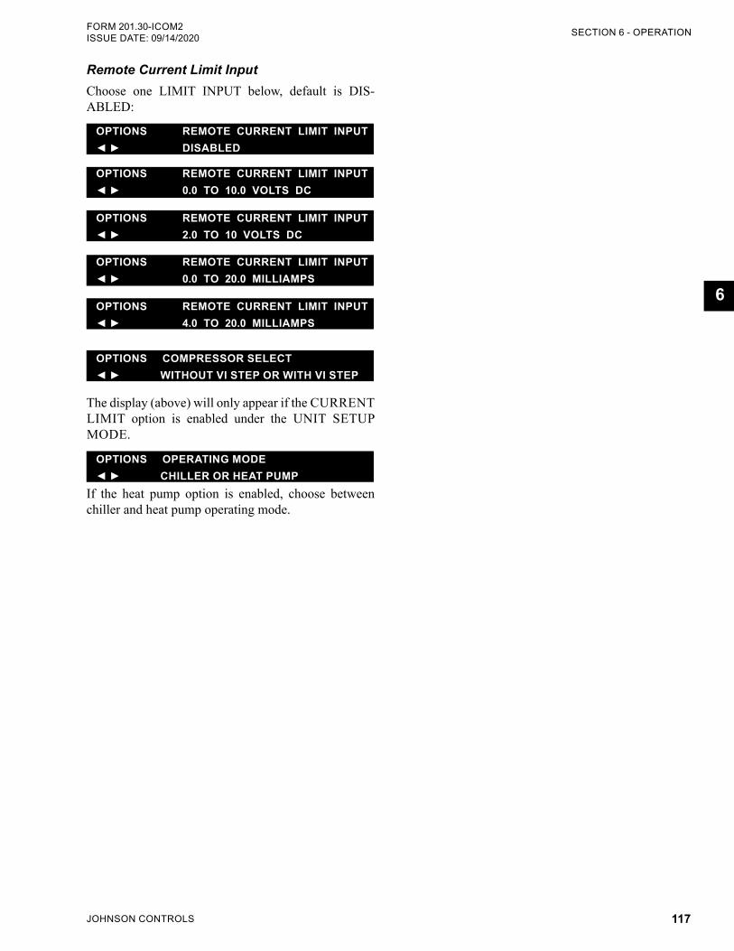
JOHNSON CONTROLS 117
SECTION 6 - OPERATIONFORM 201.30-ICOM2 ISSUE DATE: 09/14/2020
6
Remote Current Limit InputChoose one LIMIT INPUT below, default is DIS-ABLED:
OPTIONS REMOTE CURRENT LIMIT INPUT DISABLED
OPTIONS REMOTE CURRENT LIMIT INPUT 0.0 TO 10.0 VOLTS DC
OPTIONS REMOTE CURRENT LIMIT INPUT 2.0 TO 10 VOLTS DC
OPTIONS REMOTE CURRENT LIMIT INPUT 0.0 TO 20.0 MILLIAMPS
OPTIONS REMOTE CURRENT LIMIT INPUT 4.0 TO 20.0 MILLIAMPS
OPTIONS COMPRESSOR SELECT WITHOUT VI STEP OR WITH VI STEP
The display (above) will only appear if the CURRENT LIMIT option is enabled under the UNIT SETUP MODE.
OPTIONS OPERATING MODE CHILLER OR HEAT PUMP
If the heat pump option is enabled, choose between chiller and heat pump operating mode.
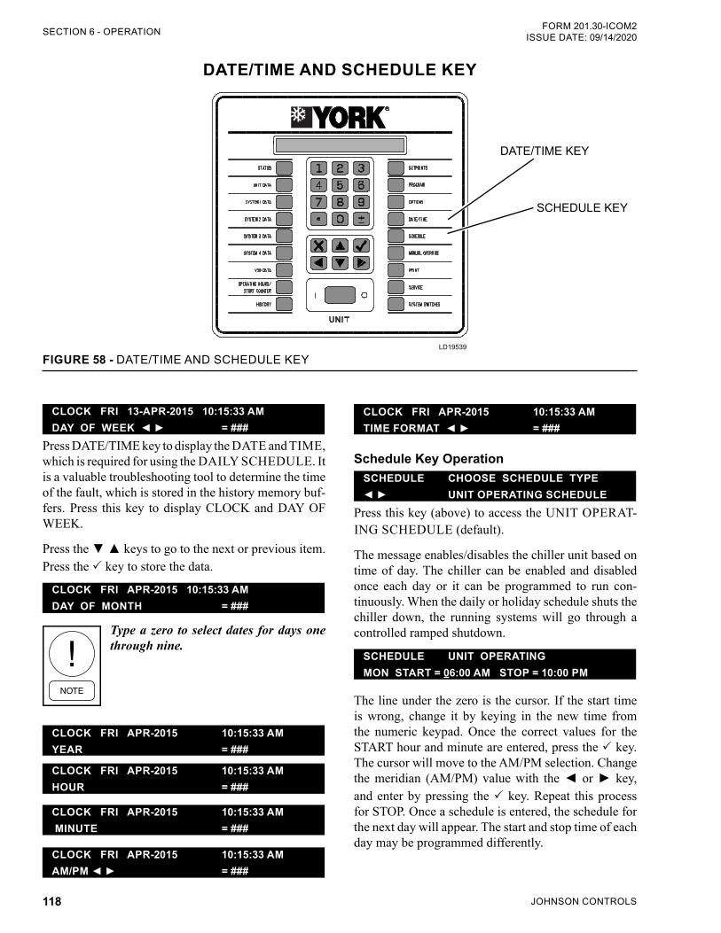
JOHNSON CONTROLS118
FORM 201.30-ICOM2ISSUE DATE: 09/14/2020SECTION 6 - OPERATION
DATE/TIME AND SCHEDULE KEY
SCHEDULE KEY
FIGURE 58 - DATE/TIME AND SCHEDULE KEYLD19539
DATE/TIME KEY
CLOCK FRI APR-2015 10:15:33 AM TIME FORMAT = ###
Schedule Key OperationSCHEDULE CHOOSE SCHEDULE TYPE UNIT OPERATING SCHEDULE
Press this key (above) to access the UNIT OPERAT-ING SCHEDULE (default).
The message enables/disables the chiller unit based on time of day. The chiller can be enabled and disabled once each day or it can be programmed to run con-tinuously. When the daily or holiday schedule shuts the chiller down, the running systems will go through a controlled ramped shutdown.
SCHEDULE UNIT OPERATINGMON START = 06:00 AM STOP = 10:00 PM
The line under the zero is the cursor. If the start time is wrong, change it by keying in the new time from the numeric keypad. Once the correct values for the START hour and minute are entered, press the key. The cursor will move to the AM/PM selection. Change the meridian (AM/PM) value with the or key, and enter by pressing the key. Repeat this process for STOP. Once a schedule is entered, the schedule for the next day will appear. The start and stop time of each day may be programmed differently.
CLOCK FRI 13-APR-2015 10:15:33 AM DAY OF WEEK = ###
Press DATE/TIME key to display the DATE and TIME, which is required for using the DAILY SCHEDULE. It is a valuable troubleshooting tool to determine the time of the fault, which is stored in the history memory buf-fers. Press this key to display CLOCK and DAY OF WEEK.
Press the keys to go to the next or previous item. Press the key to store the data.
CLOCK FRI APR-2015 10:15:33 AM DAY OF MONTH = ###
Type a zero to select dates for days one through nine.
CLOCK FRI APR-2015 10:15:33 AM YEAR = ###
CLOCK FRI APR-2015 10:15:33 AM HOUR = ###
CLOCK FRI APR-2015 10:15:33 AM MINUTE = ###
CLOCK FRI APR-2015 10:15:33 AMAM/PM = ###
JOHNSON CONTROLS 119
SECTION 6 - OPERATIONFORM 201.30-ICOM2 ISSUE DATE: 09/14/2020
6
To view the schedule without making a change, press the SCHEDULE key until the day appears. The key will scroll to the previous screen.
If the schedule is changed for Monday, all other days will change to the Monday schedule. So if the Monday times are not applicable for the whole week, then the exceptional days must be reprogrammed to the preferred schedule.
SCHEDULE UNIT OPERATINGHOL START = 00:00 AM STOP = 00:00 PM
To program the chiller for 24-hour operation, program the start and stop times of each day at 00:00.
After the SUN (Sunday) schedule appears on the dis-play,, a key will display the holiday schedule, which is a two-part display. The first display reads:
SCHEDULE UNIT OPERATINGS M T W T F S HOLIDAY NOTED BY *
Set the holiday times using the same procedure de-scribed for the days of the week. Press the key after setting the HOL START and STOP times to save the
change in memory. Press the SCHEDULE key a sec-ond time to show the individual days:
The line below the empty space is the cursor, which will move to the next or previous empty space when the or key is pressed.
To set a day for the HOLIDAY NOTED BY:
1. Move the cursor to the space following the day of the week.
2. Press the asterisk (*) key, and an * will appear in the space signifying that day as a holiday.
The holiday schedule must be programmed weekly. If there is no holiday, use the * key to delete the *. Use the key to accept the holiday schedule for the entire week.
The HOLIDAY SCHEDULE is tempo-rary. Once the schedule is executed, the selected holidays will be cleared from memory for the following week.
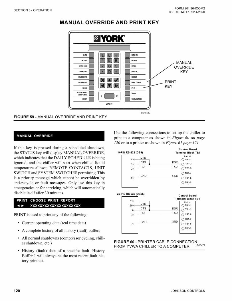
JOHNSON CONTROLS120
FORM 201.30-ICOM2ISSUE DATE: 09/14/2020SECTION 6 - OPERATION
MANUAL OVERRIDE AND PRINT KEY
FIGURE 59 - MANUAL OVERRIDE AND PRINT KEYLD19539
MANUAL OVERRIDE
KEY
PRINT KEY
Use the following connections to set up the chiller to print to a computer as shown in Figure 60 on page 120 or to a printer as shown in Figure 61 page 121.
9-PIN RS-232 (DB9)Control Board
Terminal Block TB1
DTE
CTS
RD
GND
DSR
GND
TXD
25-PIN RS-232 (DB25)
4
8
2
5
11
20
5
3
7
RS-232
RS-232 DTE
CTS
RD
GND
DSR
GND
TXD
TB1-1
TB1-2
TB1-3
TB1-4
TB1-5
TB1-6
TB1-1
TB1-2
TB1-3
TB1-4
TB1-5
TB1-6
Control Board Terminal Block TB1
FIGURE 60 - PRINTER CABLE CONNECTION FROM YVWA CHILLER TO A COMPUTER
MANUAL OVERRIDE
If this key is pressed during a scheduled shutdown, the STATUS key will display MANUAL OVERRIDE, which indicates that the DAILY SCHEDULE is being ignored, and the chiller will start when chilled liquid temperature allows; REMOTE CONTACTS, UNIT SWITCH and SYSTEM SWITCHES permitting. This is a priority message which cannot be overridden by anti-recycle or fault messages. Only use this key in emergencies or for servicing, which will automatically disable itself after 30 minutes.
PRINT CHOOSE PRINT REPORT XXXXXXXXXXXXXXXXXXXXX
PRINT is used to print any of the following:
• Current operating data (real time data)
• A complete history of all history (fault) buffers
• All normal shutdowns (compressor cycling, chill-er shutdown, etc.)
• History (fault) data of a specific fault. History Buffer 1 will always be the most recent fault his-tory printout.
LD16479
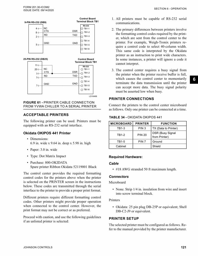
JOHNSON CONTROLS 121
SECTION 6 - OPERATIONFORM 201.30-ICOM2 ISSUE DATE: 09/14/2020
6
LD16468
9-PIN RS-232 (DB9)Control Board
Terminal Block TB1
NCCTSRD
GND
DSR
GND
TXD
25-PIN RS-232 (DB25)
4
8
2
5
11
20
5
3
7
RS-232
RS-232 NCCTSRD
GND
DSR
GND
TXD
TB1-1
TB1-2
TB1-3
TB1-4
TB1-5
TB1-6
TB1-1
TB1-2
TB1-3
TB1-4
TB1-5
TB1-6
Control Board Terminal Block TB1
FIGURE 61 - PRINTER CABLE CONNECTION FROM YVWA CHILLER TO A SERIAL PRINTER
ACCEPTABLE PRINTERSThe following printer can be used. Printers must be equipped with an RS-232 serial interface.
Okidata OKIPOS 441 Printer• Dimensions:
6.9 in. wide x 9.64 in. deep x 5.98 in. high
• Paper: 3.0 in. wide
• Type: Dot Matrix Impact
• Purchase: 800-OKIDATA Spare printer Ribbon Okidata 52119001 Black
The control center provides the required formatting control codes for the printers above when the printer is selected on the PRINTER screen in the instructions below. These codes are transmitted through the serial interface to the printer to provide a proper print format.
Different printers require different formatting control codes. Other printers might provide proper operation when connected to the control center. However, the print format may not be correct or as preferred.
Proceed with caution, and use the following guidelines if an unlisted printer is selected:
1. All printers must be capable of RS-232 serial communications.
2. The primary differences between printers involve the formatting control codes required by the print-er, which are sent from the control center to the printer. For example, Weigh -Tronix printers re-quire a control code to select 40-column width. This same code is interpreted by the Okidata printer as an instruction to print wide characters. In some instances, a printer will ignore a code it cannot interpret.
3. The control center requires a busy signal from the printer when the printer receive buffer is full, which causes the control center to momentarily terminate the data transmission until the printer can accept more data. The busy signal polarity must be asserted low when busy.
PRINTER CONNECTIONSConnect the printers to the control center microboard as follows. Only one printer can be connected at a time.
TABLE 34 - OKIDATA OKIPOS 441
MICROBOARD PRINTER FUNCTIONTB1-3 PIN 3 TX (Data to Printer)
TB1-2 PIN 20 DSR (Busy Signal from Printer)
TB1-5 PIN 7 GroundCabinet Shield
Required Hardware:
Cable• #18 AWG stranded 50 ft maximum length.
ConnectorsMicroboard
• None. Strip 1/4 in. insulation from wire and insert into screw terminal block.
Printers
• Okidata: 25 pin plug DB-25P or equivalent; Shell DB-C2-J9 or equivalent.
PRINTER SETUPThe selected printer must be configured as follows. Re-fer to the manual provided by the printer manufacturer.
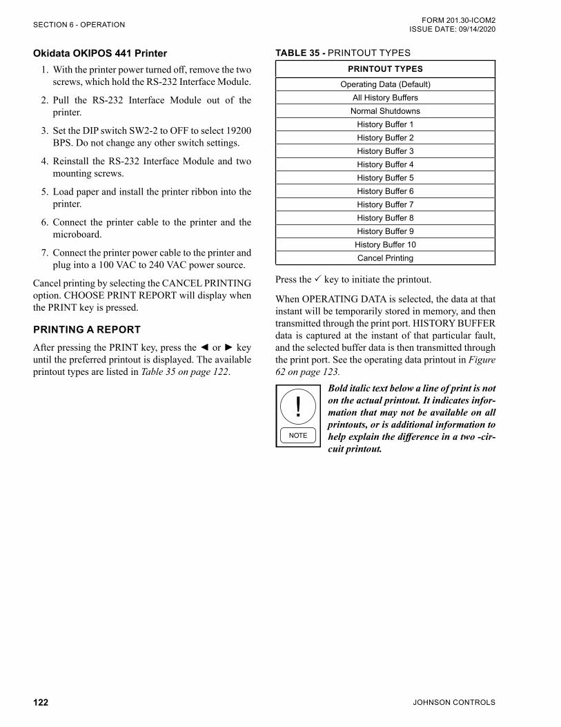
JOHNSON CONTROLS122
FORM 201.30-ICOM2ISSUE DATE: 09/14/2020SECTION 6 - OPERATION
Okidata OKIPOS 441 Printer1. With the printer power turned off, remove the two
screws, which hold the RS-232 Interface Module.
2. Pull the RS-232 Interface Module out of the printer.
3. Set the DIP switch SW2-2 to OFF to select 19200 BPS. Do not change any other switch settings.
4. Reinstall the RS-232 Interface Module and two mounting screws.
5. Load paper and install the printer ribbon into the printer.
6. Connect the printer cable to the printer and the microboard.
7. Connect the printer power cable to the printer and plug into a 100 VAC to 240 VAC power source.
Cancel printing by selecting the CANCEL PRINTING option. CHOOSE PRINT REPORT will display when the PRINT key is pressed.
PRINTING A REPORTAfter pressing the PRINT key, press the or key until the preferred printout is displayed. The available printout types are listed in Table 35 on page 122.
TABLE 35 - PRINTOUT TYPES
PRINTOUT TYPES
Operating Data (Default)All History BuffersNormal Shutdowns
History Buffer 1History Buffer 2History Buffer 3History Buffer 4History Buffer 5History Buffer 6History Buffer 7History Buffer 8History Buffer 9
History Buffer 10Cancel Printing
Press the key to initiate the printout.
When OPERATING DATA is selected, the data at that instant will be temporarily stored in memory, and then transmitted through the print port. HISTORY BUFFER data is captured at the instant of that particular fault, and the selected buffer data is then transmitted through the print port. See the operating data printout in Figure 62 on page 123.
Bold italic text below a line of print is not on the actual printout. It indicates infor-mation that may not be available on all printouts, or is additional information to help explain the difference in a two -cir-cuit printout.
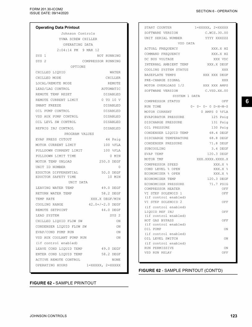
JOHNSON CONTROLS 123
SECTION 6 - OPERATIONFORM 201.30-ICOM2 ISSUE DATE: 09/14/2020
6
Operating Data PrintoutJohnson Controls
YVWA SCREW CHILLER
OPERATING DATA
2:04:14 PM 9 MAR 12
SYS 1 NOT RUNNING
SYS 2 COMPRESSOR RUNNING
OPTIONS
CHILLED LIQUID WATER
CHILLED MODE CHILLER
LOCAL/REMOTE MODE REMOTE
LEAD/LAG CONTROL AUTOMATIC
REMOTE TEMP RESET DISABLED
REMOTE CURRENT LIMIT 0 TO 10 V
SMART FREEZE DISABLED
OIL PUMP CONTROL DISABLED
VSD AUX PUMP CONTROL DISABLED
OIL LEVL SW CONTROL DISABLED
REFRIG INJ CONTROL DISABLED
PROGRAM VALUES
EVAP PRESS CUTOUT 44 Psig
MOTOR CURRENT LIMIT 100 %FLA
PULLDOWN CURRENT LIMIT 100 %FLA
PULLDOWN LIMIT TIME 0 MIN
MOTOR TEMP UNLOAD 250.0 DEGF
UNIT ID NUMBER 0
EDUCTOR DIFFERENTIAL 50.0 DEGF EDUCTOR SAFETY TIME 10 MIN
UNIT DATA
LEAVING WATER TEMP 49.0 DEGF
RETURN WATER TEMP 58.2 DEGF
TEMP RATE XXX.X DEGF/MIN
COOLING RANGE 42.0+/-2.0 DEGF
REMOTE SETPOINT 44.0 DEGF
LEAD SYSTEM SYS 2
CHILLED LIQUID FLOW SW ON
CONDENSER LIQUID FLOW SW ON
EVAP/COND PUMP RUN ON
VSD AUX COOLANT PUMP RUN ON
(if control enabled)
LEAVE COND LIQUID TEMP 49.0 DEGF
ENTER COND LIQUID TEMP 58.2 DEGF
ACTIVE REMOTE CONTROL NONE
OPERATING HOURS 1=XXXXX, 2=XXXXX
FIGURE 62 - SAMPLE PRINTOUT
START COUNTER 1=XXXXX, 2=XXXXX
SOFTWARE VERSION C.WCS.30.00
UNIT SERIAL NUMBER YYYY XXXZZZ
VSD DATA
ACTUAL FREQUENCY XXX.X HZ
COMMAND FREQUENCY XXX.X HZ
DC BUS VOLTAGE XXX VDC
INTERNAL AMBIENT TEMP XXX.X DEGF
COOLING SYSTEM STATUS XXX
BASEPLATE TEMPS XXX XXX DEGF
PRE-CHARGE SIGNAL XXX
MOTOR OVERLOADS 1/2 XXX XXX AMPS
SOFTWARE VERSION C.VSD.XX.00
SYSTEM 1 DATA
COMPRESSOR STATUS OFF
RUN TIME 0- 0- 0- 0 D-H-M-S
MOTOR CURRENT 0 AMPS 0 %FLA
EVAPORATOR PRESSURE 125 Psig
DISCHARGE PRESSURE 131 Psig
OIL PRESSURE 130 Psig
CONDENSER LIQUID TEMP 68.4 DEGF
DISCHARGE TEMPERATURE 68.8 DEGF
CONDENSER PRESSURE 71.8 DEGF
SUBCOOLING 3.4 DEGF
EVAP TEMP 120.3 DEGF
MOTOR TMP XXX.XXXX.XXXX.X
COMPRESSOR SPEED XXX.X %COND LEVEL % OPEN XXX.X %ECONOMIZER % OPEN XXX.X %
ECONOMIZER TEMP 120.3 DEGF
ECONOMIZER PRESSURE 71.7 PSIGCOMPRESSOR HEATER OFFVI STEP SOLENOID 1 OFF (if control enabled)VI STEP SOLENOID 2 OFF
(if control enabled)LIQUID REF INJ OFF (if control enabled)HOT GAS BYPASS OFF (if control enabled)OIL PUMP ON
(if control enabled)OIL LEVEL SWITCH ON
(if control enabled)RUN PERMISSIVE ONVSD RUN RELAY OFF
FIGURE 62 - SAMPLE PRINTOUT (CONT'D)
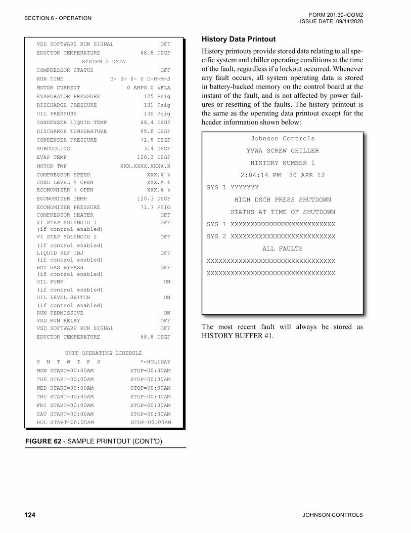
JOHNSON CONTROLS124
FORM 201.30-ICOM2ISSUE DATE: 09/14/2020SECTION 6 - OPERATION
VSD SOFTWARE RUN SIGNAL OFF
EDUCTOR TEMPERATURE 68.8 DEGF
SYSTEM 2 DATA
COMPRESSOR STATUS OFF
RUN TIME 0- 0- 0- 0 D-H-M-S
MOTOR CURRENT 0 AMPS 0 %FLA
EVAPORATOR PRESSURE 125 Psig
DISCHARGE PRESSURE 131 Psig
OIL PRESSURE 130 Psig
CONDENSER LIQUID TEMP 68.4 DEGF
DISCHARGE TEMPERATURE 68.8 DEGF
CONDENSER PRESSURE 71.8 DEGF
SUBCOOLING 3.4 DEGF
EVAP TEMP 120.3 DEGF
MOTOR TMP XXX.XXXX.XXXX.X
COMPRESSOR SPEED XXX.X %COND LEVEL % OPEN XXX.X %ECONOMIZER % OPEN XXX.X %
ECONOMIZER TEMP 120.3 DEGF
ECONOMIZER PRESSURE 71.7 PSIGCOMPRESSOR HEATER OFFVI STEP SOLENOID 1 OFF (if control enabled)VI STEP SOLENOID 2 OFF
(if control enabled)LIQUID REF INJ OFF (if control enabled)HOT GAS BYPASS OFF (if control enabled)OIL PUMP ON
(if control enabled)OIL LEVEL SWITCH ON
(if control enabled)RUN PERMISSIVE ONVSD RUN RELAY OFFVSD SOFTWARE RUN SIGNAL OFF
EDUCTOR TEMPERATURE 68.8 DEGF
UNIT OPERATING SCHEDULE
S M T W T F S *=HOLIDAY
MON START=00:00AM STOP=00:00AM
TUE START=00:00AM STOP=00:00AM
WED START=00:00AM STOP=00:00AM
THU START=00:00AM STOP=00:00AM
FRI START=00:00AM STOP=00:00AM
SAT START=00:00AM STOP=00:00AM
HOL START=00:00AM STOP=00:00AM
FIGURE 62 - SAMPLE PRINTOUT (CONT'D)
History Data PrintoutHistory printouts provide stored data relating to all spe-cific system and chiller operating conditions at the time of the fault, regardless if a lockout occurred. Whenever any fault occurs, all system operating data is stored in battery-backed memory on the control board at the instant of the fault, and is not affected by power fail-ures or resetting of the faults. The history printout is the same as the operating data printout except for the header information shown below:
Johnson Controls
YVWA SCREW CHILLER
HISTORY NUMBER 1
2:04:14 PM 30 APR 12
SYS 1 YYYYYYY
HIGH DSCH PRESS SHUTDOWN
STATUS AT TIME OF SHUTDOWN
SYS 1 XXXXXXXXXXXXXXXXXXXXXXXXXX
SYS 2 XXXXXXXXXXXXXXXXXXXXXXXXXX
ALL FAULTS
XXXXXXXXXXXXXXXXXXXXXXXXXXXXXXXX
XXXXXXXXXXXXXXXXXXXXXXXXXXXXXXXX
The most recent fault will always be stored as HISTORY BUFFER #1.
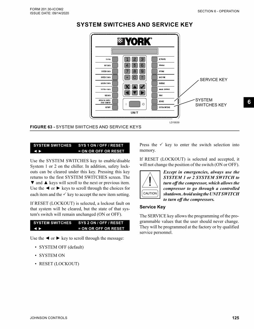
JOHNSON CONTROLS 125
SECTION 6 - OPERATIONFORM 201.30-ICOM2 ISSUE DATE: 09/14/2020
6
SYSTEM SWITCHES AND SERVICE KEY
FIGURE 63 - SYSTEM SWITCHES AND SERVICE KEYSLD19539
SYSTEM SWITCHES KEY
SERVICE KEY
Press the key to enter the switch selection into memory.
If RESET (LOCKOUT) is selected and accepted, it will not change the position of the switch (ON or OFF).
Except in emergencies, always use the SYSTEM 1 or 2 SYSTEM SWITCH to turn off the compressor, which allows the compressor to go through a controlled shutdown. Avoid using the UNIT SWITCH to turn off the compressors.
Service Key
The SERVICE key allows the programming of the pro-grammable values that the user should never change. They will be programmed at the factory or by qualified service personnel.
SYSTEM SWITCHES SYS 1 ON / OFF / RESET = ON OR OFF OR RESET
Use the SYSTEM SWITCHES key to enable/disable System 1 or 2 on the chiller. In addition, safety lock-outs can be cleared under this key. Pressing this key returns to the first SYSTEM SWITCHES screen. The and keys will scroll to the next or previous item. Use the or keys to scroll through the choices for each item and the key to accept the new item setting.
If RESET (LOCKOUT) is selected, a lockout fault on that system will be cleared, but the state of that sys-tem's switch will remain unchanged (ON or OFF).
SYSTEM SWITCHES SYS 2 ON / OFF / RESET = ON OR OFF OR RESET
Use the or key to scroll through the message:
• SYSTEM OFF (default)
• SYSTEM ON
• RESET (LOCKOUT)
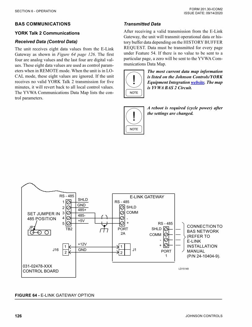
JOHNSON CONTROLS126
FORM 201.30-ICOM2ISSUE DATE: 09/14/2020SECTION 6 - OPERATION
BAS COMMUNICATIONS
YORK Talk 2 Communications
Received Data (Control Data)The unit receives eight data values from the E-Link Gateway as shown in Figure 64 page 126. The first four are analog values and the last four are digital val-ues. These eight data values are used as control param-eters when in REMOTE mode. When the unit is in LO-CAL mode, these eight values are ignored. If the unit receives no valid YORK Talk 2 transmission for five minutes, it will revert back to all local control values. The YVWA Communications Data Map lists the con-trol parameters.
Transmitted DataAfter receiving a valid transmission from the E-Link Gateway, the unit will transmit operational data or his-tory buffer data depending on the HISTORY BUFFER REQUEST. Data must be transmitted for every page under Feature 54. If there is no value to be sent to a particular page, a zero will be sent to the YVWA Com-munications Data Map.
The most current data map information is listed on the Johnson Controls/YORK Equipment Integration website. The map is YVWA BAS 2 Circuit.
A reboot is required (cycle power) after the settings are changed.
LD15148
12
12
J16
JP1
J1+12V
TB2
PORT 1
PORT 2A
54321
GND
SHLD
SHLDCOMM
RS - 485RS - 485
RS - 485
GND485+485-+5V -
+SHLD
COMM-+
031-02478-XXXCONTROL BOARD
E-LINK GATEWAY
CONNECTION TOBAS NETWORK(REFER TO E-LINKINSTALLATION MANUAL(P/N 24-10404-9).
SET JUMPER IN 485 POSITION
FIGURE 64 - E-LINK GATEWAY OPTION
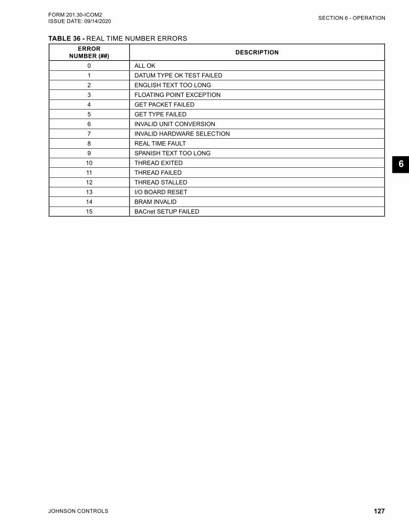
JOHNSON CONTROLS 127
SECTION 6 - OPERATIONFORM 201.30-ICOM2 ISSUE DATE: 09/14/2020
6
TABLE 36 - REAL TIME NUMBER ERRORSERROR
NUMBER (##) DESCRIPTION
0 ALL OK1 DATUM TYPE OK TEST FAILED2 ENGLISH TEXT TOO LONG3 FLOATING POINT EXCEPTION4 GET PACKET FAILED5 GET TYPE FAILED6 INVALID UNIT CONVERSION7 INVALID HARDWARE SELECTION8 REAL TIME FAULT9 SPANISH TEXT TOO LONG
10 THREAD EXITED11 THREAD FAILED12 THREAD STALLED13 I/O BOARD RESET14 BRAM INVALID15 BACnet SETUP FAILED

JOHNSON CONTROLS128
FORM 201.30-ICOM2ISSUE DATE: 09/14/2020
THIS PAGE INTENTIONALLY LEFT BLANK.
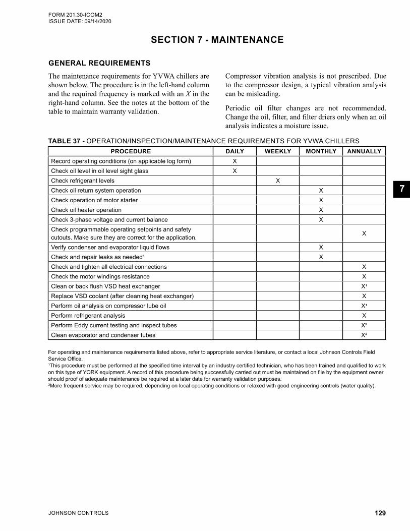
JOHNSON CONTROLS 129
FORM 201.30-ICOM2 ISSUE DATE: 09/14/2020
7
SECTION 7 - MAINTENANCE
GENERAL REQUIREMENTSThe maintenance requirements for YVWA chillers are shown below. The procedure is in the left-hand column and the required frequency is marked with an X in the right-hand column. See the notes at the bottom of the table to maintain warranty validation.
TABLE 37 - OPERATION/INSPECTION/MAINTENANCE REQUIREMENTS FOR YVWA CHILLERSPROCEDURE DAILY WEEKLY MONTHLY ANNUALLY
Record operating conditions (on applicable log form) XCheck oil level in oil level sight glass XCheck refrigerant levels XCheck oil return system operation XCheck operation of motor starter XCheck oil heater operation XCheck 3-phase voltage and current balance XCheck programmable operating setpoints and safety cutouts. Make sure they are correct for the application. X
Verify condenser and evaporator liquid flows XCheck and repair leaks as needed¹ XCheck and tighten all electrical connections XCheck the motor windings resistance XClean or back flush VSD heat exchanger X¹
Replace VSD coolant (after cleaning heat exchanger) XPerform oil analysis on compressor lube oil X¹
Perform refrigerant analysis XPerform Eddy current testing and inspect tubes X²Clean evaporator and condenser tubes X²
For operating and maintenance requirements listed above, refer to appropriate service literature, or contact a local Johnson Controls Field Service Office.¹This procedure must be performed at the specified time interval by an industry certified technician, who has been trained and qualified to work on this type of YORK equipment. A record of this procedure being successfully carried out must be maintained on file by the equipment owner should proof of adequate maintenance be required at a later date for warranty validation purposes.²More frequent service may be required, depending on local operating conditions or relaxed with good engineering controls (water quality).
Compressor vibration analysis is not prescribed. Due to the compressor design, a typical vibration analysis can be misleading.
Periodic oil filter changes are not recommended. Change the oil, filter, and filter driers only when an oil analysis indicates a moisture issue.
JOHNSON CONTROLS130
FORM 201.30-ICOM2ISSUE DATE: 09/14/2020SECTION 7 - MAINTENANCE
DAILY OPERATING INSPECTIONS
Routine InspectionsAvoid serious operating difficulties by conducting reg-ular inspections. Use the following list of daily inspec-tions and procedures as a guide.
Check or verify the following:
1. Control center displays.
2. If the compressor is in operation,
c. Check the oil pressure.
d. Check the oil level in the oil reservoir.
e. Drain or add oil, as necessary.
3. Entering and leaving condenser water pressure and temperatures for comparison with job design conditions.
4. Entering and leaving chilled liquid temperatures and evaporator pressure for comparison with job design conditions.
5. Condenser saturation temperature (based upon condenser pressure sensed by the condenser trans-ducer).
6. Signs of dirty or fouled condenser tubes. (The temperature difference between water leaving condenser and condenser refrigerant saturation should not exceed the difference recorded for a new unit by more than 4°F (2°C)).
7. Compressor discharge temperature. During nor-mal operation, discharge temperature should not exceed 212°F (100°C).
8. Compressor motor voltage and current (amps) on the control center display.
9. Proper water treatment.
Press the STATUS key whenever the display indicates to do so, which allows any warning messages to be dis-played.
COMPRESSOR OIL
Check Operational Oil LevelEach compressor requires 9 L (2.4 gal) of YORK L oil per system.
Oil LevelThe YVWA chiller DOES NOT HAVE an oil pump. System oil flow is dependent on the pressure differen-tial between the condenser and evaporator. Therefore, the oil flow rate, and oil level in the separator will vary as the system pressures and compressor speeds change. It is normal for the oil level to be at the bottom of the lower sight glass, or near the top of the upper sight glass on the oil separator, depending on conditions.
Oil should NOT be added unless the oil level cannot be seen in the lower sight glass when the compressor is operating at least 100 Hz. At lower loads, oil level may be below the lower sight glass, but with the proper amount of oil in the chiller, an adequate amount of oil is provided to compressor at those loads even with partial refrigerant in the stream. Oil should not be removed unless the oil level is above the upper sight glass. If oil needs to be added, use the procedure below to manage the oil level.
Oil should NOT be added unless the oil level cannot be seen in the lower sight glass, or removed unless the oil level is above the upper sight glass. If oil needs to be added, use the procedure below to manage the oil level.
Start-Up1. Oil level cannot be seen in the lower or upper
sight glass: For chillers shipped with a factory charge of oil and refrigerant with no oil level ob-vious at start-up, a qualified technician should add only enough oil to create a visible level in the bot-tom of the lower sight glass.
Start the chiller and run a load condition between 65% and 80% FLA for a minimum of one hour and observe the oil level. The oil level should become visible in the lower or upper sight glass, depending on conditions. A qualified technician should then remove the approximate amount add-ed to start the chiller.
2. Oil level is above the upper sight glass: Con-ditions can exist where the evaporator pressure is higher than the condenser pressure, which oc-curs when the evaporator (or chilled) water loop is warmer than the condenser (or cooling tower) water loop, which can cause refrigerant in the oil separator to condense, creating a liquid level (oil and refrigerant mixture) that exceeds the top of the upper sight glass.
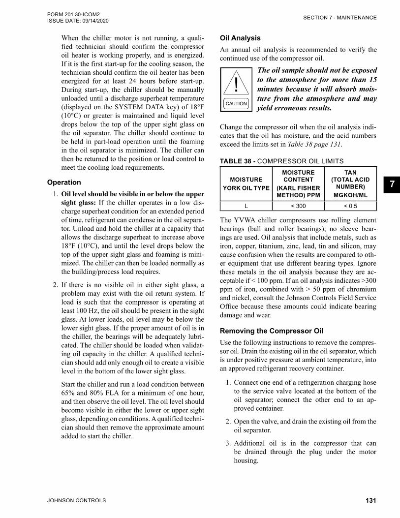
JOHNSON CONTROLS 131
SECTION 7 - MAINTENANCEFORM 201.30-ICOM2 ISSUE DATE: 09/14/2020
7
When the chiller motor is not running, a quali-fied technician should confirm the compressor oil heater is working properly, and is energized. If it is the first start-up for the cooling season, the technician should confirm the oil heater has been energized for at least 24 hours before start-up. During start-up, the chiller should be manually unloaded until a discharge superheat temperature (displayed on the SYSTEM DATA key) of 18°F (10°C) or greater is maintained and liquid level drops below the top of the upper sight glass on the oil separator. The chiller should continue to be held in part-load operation until the foaming in the oil separator is minimized. The chiller can then be returned to the position or load control to meet the cooling load requirements.
Operation1. Oil level should be visible in or below the upper
sight glass: If the chiller operates in a low dis-charge superheat condition for an extended period of time, refrigerant can condense in the oil separa-tor. Unload and hold the chiller at a capacity that allows the discharge superheat to increase above 18°F (10°C), and until the level drops below the top of the upper sight glass and foaming is mini-mized. The chiller can then be loaded normally as the building/process load requires.
2. If there is no visible oil in either sight glass, a problem may exist with the oil return system. If load is such that the compressor is operating at least 100 Hz, the oil should be present in the sight glass. At lower loads, oil level may be below the lower sight glass. If the proper amount of oil is in the chiller, the bearings will be adequately lubri-cated. The chiller should be loaded when validat-ing oil capacity in the chiller. A qualified techni-cian should add only enough oil to create a visible level in the bottom of the lower sight glass.
Start the chiller and run a load condition between 65% and 80% FLA for a minimum of one hour, and then observe the oil level. The oil level should become visible in either the lower or upper sight glass, depending on conditions. A qualified techni-cian should then remove the approximate amount added to start the chiller.
Oil AnalysisAn annual oil analysis is recommended to verify the continued use of the compressor oil.
The oil sample should not be exposed to the atmosphere for more than 15 minutes because it will absorb mois-ture from the atmosphere and may yield erroneous results.
Change the compressor oil when the oil analysis indi-cates that the oil has moisture, and the acid numbers exceed the limits set in Table 38 page 131.
TABLE 38 - COMPRESSOR OIL LIMITS
MOISTURE YORK OIL TYPE
MOISTURE CONTENT
(KARL FISHER METHOD) PPM
TAN (TOTAL ACID
NUMBER) MGKOH/ML
L < 300 < 0.5
The YVWA chiller compressors use rolling element bearings (ball and roller bearings); no sleeve bear-ings are used. Oil analysis that include metals, such as iron, copper, titanium, zinc, lead, tin and silicon, may cause confusion when the results are compared to oth-er equipment that use different bearing types. Ignore these metals in the oil analysis because they are ac-ceptable if < 100 ppm. If an oil analysis indicates >300 ppm of iron, combined with > 50 ppm of chromium and nickel, consult the Johnson Controls Field Service Office because these amounts could indicate bearing damage and wear.
Removing the Compressor OilUse the following instructions to remove the compres-sor oil. Drain the existing oil in the oil separator, which is under positive pressure at ambient temperature, into an approved refrigerant recovery container.
1. Connect one end of a refrigeration charging hose to the service valve located at the bottom of the oil separator; connect the other end to an ap-proved container.
2. Open the valve, and drain the existing oil from the oil separator.
3. Additional oil is in the compressor that can be drained through the plug under the motor housing.
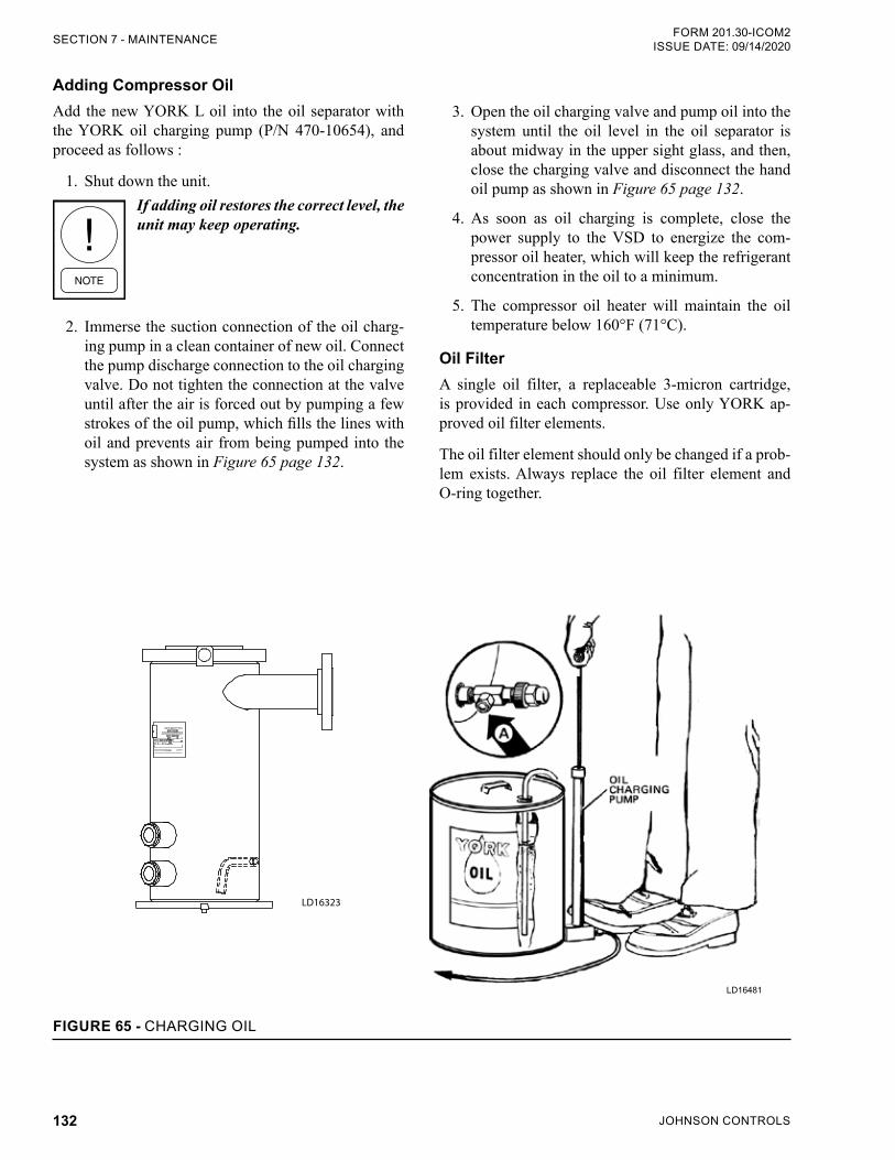
JOHNSON CONTROLS132
FORM 201.30-ICOM2ISSUE DATE: 09/14/2020SECTION 7 - MAINTENANCE
Adding Compressor OilAdd the new YORK L oil into the oil separator with the YORK oil charging pump (P/N 470-10654), and proceed as follows :
1. Shut down the unit.If adding oil restores the correct level, the unit may keep operating.
2. Immerse the suction connection of the oil charg-ing pump in a clean container of new oil. Connect the pump discharge connection to the oil charging valve. Do not tighten the connection at the valve until after the air is forced out by pumping a few strokes of the oil pump, which fills the lines with oil and prevents air from being pumped into the system as shown in Figure 65 page 132.
3. Open the oil charging valve and pump oil into the system until the oil level in the oil separator is about midway in the upper sight glass, and then, close the charging valve and disconnect the hand oil pump as shown in Figure 65 page 132.
4. As soon as oil charging is complete, close the power supply to the VSD to energize the com-pressor oil heater, which will keep the refrigerant concentration in the oil to a minimum.
5. The compressor oil heater will maintain the oil temperature below 160°F (71°C).
Oil FilterA single oil filter, a replaceable 3-micron cartridge, is provided in each compressor. Use only YORK ap-proved oil filter elements.
The oil filter element should only be changed if a prob-lem exists. Always replace the oil filter element and O-ring together.
LD16481
FIGURE 65 - CHARGING OIL
LD16323
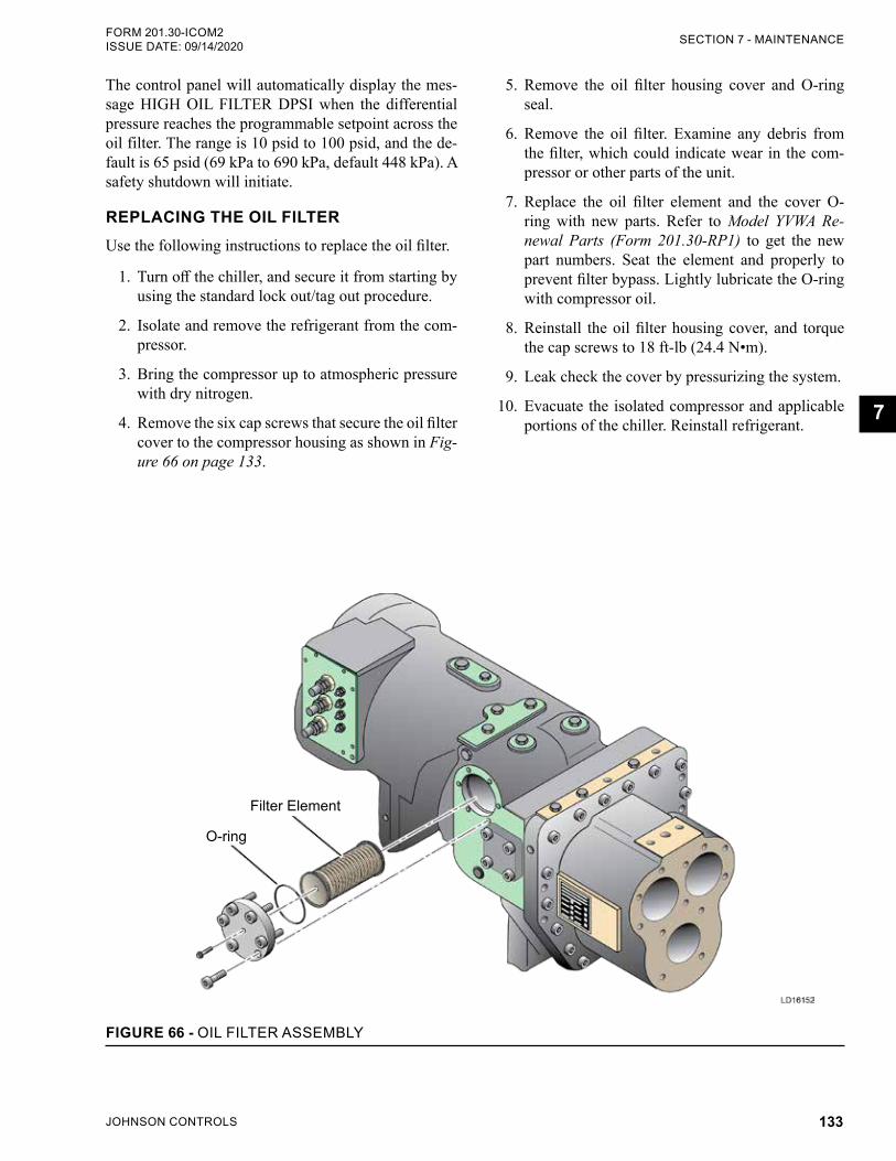
JOHNSON CONTROLS 133
SECTION 7 - MAINTENANCEFORM 201.30-ICOM2 ISSUE DATE: 09/14/2020
7
The control panel will automatically display the mes-sage HIGH OIL FILTER DPSI when the differential pressure reaches the programmable setpoint across the oil filter. The range is 10 psid to 100 psid, and the de-fault is 65 psid (69 kPa to 690 kPa, default 448 kPa). A safety shutdown will initiate.
REPLACING THE OIL FILTERUse the following instructions to replace the oil filter.
1. Turn off the chiller, and secure it from starting by using the standard lock out/tag out procedure.
2. Isolate and remove the refrigerant from the com-pressor.
3. Bring the compressor up to atmospheric pressure with dry nitrogen.
4. Remove the six cap screws that secure the oil filter cover to the compressor housing as shown in Fig-ure 66 on page 133.
5. Remove the oil filter housing cover and O-ring seal.
6. Remove the oil filter. Examine any debris from the filter, which could indicate wear in the com-pressor or other parts of the unit.
7. Replace the oil filter element and the cover O-ring with new parts. Refer to Model YVWA Re-newal Parts (Form 201.30-RP1) to get the new part numbers. Seat the element and properly to prevent filter bypass. Lightly lubricate the O-ring with compressor oil.
8. Reinstall the oil filter housing cover, and torque the cap screws to 18 ft-lb (24.4 N•m).
9. Leak check the cover by pressurizing the system.
10. Evacuate the isolated compressor and applicable portions of the chiller. Reinstall refrigerant.
FIGURE 66 - OIL FILTER ASSEMBLY
Filter Element
O-ring
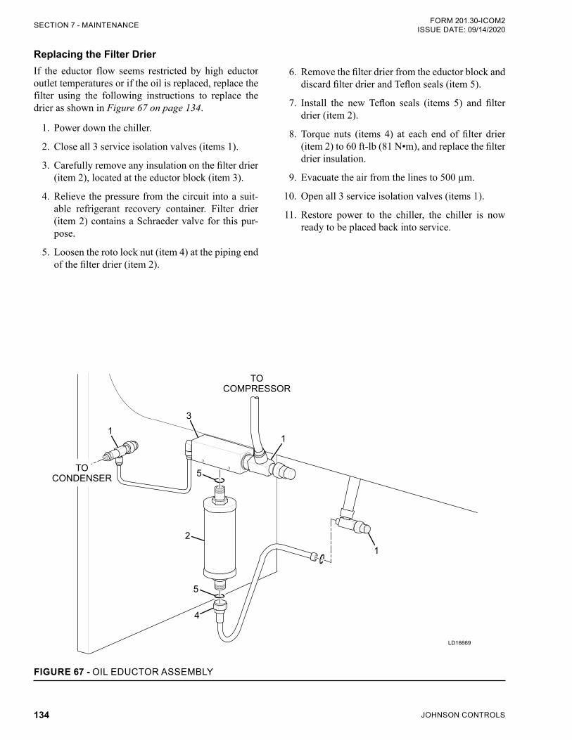
JOHNSON CONTROLS134
FORM 201.30-ICOM2ISSUE DATE: 09/14/2020SECTION 7 - MAINTENANCE
Replacing the Filter DrierIf the eductor flow seems restricted by high eductor outlet temperatures or if the oil is replaced, replace the filter using the following instructions to replace the drier as shown in Figure 67 on page 134.
1. Power down the chiller.
2. Close all 3 service isolation valves (items 1).
3. Carefully remove any insulation on the filter drier (item 2), located at the eductor block (item 3).
4. Relieve the pressure from the circuit into a suit-able refrigerant recovery container. Filter drier (item 2) contains a Schraeder valve for this pur-pose.
5. Loosen the roto lock nut (item 4) at the piping end of the filter drier (item 2).
6. Remove the filter drier from the eductor block and discard filter drier and Teflon seals (item 5).
7. Install the new Teflon seals (items 5) and filter drier (item 2).
8. Torque nuts (items 4) at each end of filter drier (item 2) to 60 ft-lb (81 N•m), and replace the filter drier insulation.
9. Evacuate the air from the lines to 500 µm.
10. Open all 3 service isolation valves (items 1).
11. Restore power to the chiller, the chiller is now ready to be placed back into service.
LD16669
1
TOCOMPRESSOR
TOCONDENSER
5
2
5
4
1
1
3
FIGURE 67 - OIL EDUCTOR ASSEMBLY
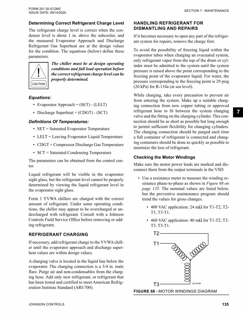
JOHNSON CONTROLS 135
SECTION 7 - MAINTENANCEFORM 201.30-ICOM2 ISSUE DATE: 09/14/2020
7
Determining Correct Refrigerant Charge LevelThe refrigerant charge level is correct when the con-denser level is about 1 in. above the subcooler, and the measured Evaporator Approach and Discharge Refrigerant Gas Superheat are at the design values for the condition. The equations (below) define these parameters.
The chiller must be at design operating conditions and full load operation before the correct refrigerant charge level can be properly determined.
Equations:• Evaporator Approach = (SET) - (LELT)
• Discharge Superheat = (CDGT) - (SCT)
Definitions Of Temperatures:• SET = Saturated Evaporator Temperature
• LELT = Leaving Evaporator Liquid Temperature
• CDGT = Compressor Discharge Gas Temperature
• SCT = Saturated Condensing Temperature
The parameters can be obtained from the control cen-ter.
Liquid refrigerant will be visible in the evaporator sight glass, but the refrigerant level cannot be properly determined by viewing the liquid refrigerant level in the evaporator sight glass.
Form 1 YVWA chillers are charged with the correct amount of refrigerant. Under some operating condi-tions, the chiller may appear to be overcharged or un-dercharged with refrigerant. Consult with a Johnson Controls Field Service Office before removing or add-ing refrigerant.
REFRIGERANT CHARGINGIf necessary, add refrigerant charge to the YVWA chill-er until the evaporator approach and discharge super-heat values are within design values.
A charging valve is located in the liquid line below the evaporator. The charging connection is a 3/4 in. male flare. Purge air and non-condensables from the charg-ing hose. Add only new refrigerant, or refrigerant that has been tested and certified to meet American Refrig-eration Institute Standard (ARI-700).
HANDLING REFRIGERANT FOR DISMANTLING AND REPAIRSIf it becomes necessary to open any part of the refriger-ant system for repairs, remove the charge first.
To avoid the possibility of freezing liquid within the evaporator tubes when charging an evacuated system, only refrigerant vapor from the top of the drum or cyl-inder must be admitted to the system until the system pressure is raised above the point corresponding to the freezing point of the evaporator liquid. For water, the pressure corresponding to the freezing point is 29 psig (20 kPa) for R-134a (at sea level).
While charging, take every precaution to prevent air from entering the system. Make up a suitable charg-ing connection from new copper tubing or approved refrigerant hose to fit between the system charging valve and the fitting on the charging cylinder. This con-nection should be as short as possible but long enough to permit sufficient flexibility for changing cylinders. The charging connection should be purged each time a full container of refrigerant is connected and chang-ing containers should be done as quickly as possible to minimize the loss of refrigerant.
Checking the Motor WindingsMake sure the motor power leads are marked and dis-connect them from the output terminals in the VSD.
• Use a resistance meter to measure the winding re-sistance phase-to-phase as shown in Figure 68 on page 135. The nominal values are listed below, but the preventive maintenance program should trend the values for gross changes.
• 400 VAC application: 24 mΩ for T1-T2, T2-T3, T3-T1.
• 460 VAC application: 40 mΩ for T1-T2, T2-T3, T3-T1.
LD16148
T2
T1
T3FIGURE 68 - MOTOR WINDINGS DIAGRAM
JOHNSON CONTROLS136
FORM 201.30-ICOM2ISSUE DATE: 09/14/2020SECTION 7 - MAINTENANCE
• Use a reliable battery-powered megohm tester, which provides a consistent test voltage to test winding resistance to ground.
• Test no greater than 500 V.
• Always test with refrigerant or nitrogen pres-sure in the motor.
• Never test in a vacuum.
• Values should be above 5 megohm.
• Trend readings for gross changes.
If values indicate a potential problem, remove the ex-ternal leads from the motor, and repeat the test directly at the motor terminals.
Never have power on the input to the VSD, nor perform megohm testing with the motor in a vacuum.
CHECKING SYSTEM FOR LEAKS
Leak Testing During OperationThe refrigerant side of the system is carefully pressure tested and evacuated at the factory.
After the system is in operation under load, the high pressure components should be carefully leak tested with a leak detector to make sure all joints are tight. If a leak exists, the refrigerant will be lost.
REFRIGERANT LEAK CHECKINGCheck for refrigerant leaks regularly as part of a com-prehensive maintenance program.
• Leak check the entire chiller, using a calibrated electronic leak detector.
• If leaks are detected, use a soap solution to con-firm leaks that were found by the leak detector.
• Check refrigerant relief valve piping and evapora-tor and condenser tube rolled joints.
PRESSURE CONNECTIONSAll threaded pressure connections used on the YVWA chillers are SAE straight thread, O-ring face seal fit-tings or Primore Roto lock fittings.
The O-ring straight thread and face seal fittings are de-signed and used in accordance with SAE J1926 and J1453. When a fitting is removed, replace the O-rings. Use only elastomeric replacement O-rings, which can be ordered from the local Johnson Controls Field Ser-vice Office.
Pipe sealant compounds are not required with SAE O-ring fittings. The O-ring seal accomplishes the pres-sure sealing. Lubricate the O-ring with compressor oil before assembly.
All filter driers and angle shutoff valves use roto lock fittings, which use a teflon fiber seal washer. Replace the washers when the filter driers are changed.
If any leaks are indicated, repair them immediately. Usually, leaks can be stopped by tightening the flare nuts or flange bolts. However, if it is necessary to re-pair a welded joint, the refrigerant charge must be re-moved.
Conduct R-134a Pressure TestWith the R-134a charge removed and all known leaks repaired, charge the system with a small amount of R-134a mixed with dry nitrogen so that a halide torch or electronic leak detector can be used to detect any leaks too small to be found using the soap test.
To test with R-134a, proceed as follows:
1. With no pressure in the system, charge R-134a gas and dry nitrogen into the system through the charging valve to a pressure of 150 psig (10 kPa).
2. To make sure that the concentration of refriger-ant reached all parts of the system, slightly open the oil charging valve and test for the presence of refrigerant with a leak detector.
3. Test around each joint and factory weld carefully and thoroughly.
4. To check for refrigerant leaks in the evaporator and condenser, open the vents in the evaporator and condenser heads and test for the presence of refrigerant. If no refrigerant is present, the tubes and tube sheets may be considered tight. If refrig-erant is detected at the vents, remove the heads, locate the leak, (using the soap test or leak detec-tor) and repair.
5. When system is absolutely tight, blow the nitro-gen and refrigerant mixture through the charging valve.
JOHNSON CONTROLS 137
SECTION 7 - MAINTENANCEFORM 201.30-ICOM2 ISSUE DATE: 09/14/2020
7
TESTING FOR EVAPORATOR AND CONDENSER TUBE LEAKSEvaporator and condenser tube leaks in R-134a sys-tems may result in refrigerant leaking into the water circuit, or into the shell, depending on the pressure lev-els.
If refrigerant is leaking into the water, it can be detect-ed at the liquid head vents after a period of shutdown. If water is leaking into the refrigerant, system capacity and efficiency will drop off sharply.
If a tube is leaking and water has entered the system, the evaporator and condenser should be valved off from the rest of the water circuit and drained immediately to prevent severe rusting and corrosion. The refrigerant system should then be drained and purged with dry ni-trogen to prevent severe rusting and corrosion. If a tube leak is indicated, determine the exact location of the leak using the following information:
1. Remove the heads and listen at each section of the tubes for a hissing sound that would indicate gas leakage, which will help locate the section of the tubes to be further investigated. If the prob-able location of the leaky tubes has been deter-mined, treat that section in the following manner (if the location is not definite, investigate all of the tubes).
2. Wash off both tube heads and the ends of all tubes with water.
Do not use carbon tetrachloride for this purpose since its fumes give the same flame discoloration that the refrigerant does.
3. With nitrogen or dry air, blow out the tubes to clear them of traces of refrigerant laden moisture from the circulation water. As soon as the tubes are clear, a cork should be driven into each end of the tube. Pressurize the dry system with 50 psig to 100 psig (345 kPa to 690 kPa) of nitrogen. Repeat this process with all of the other tubes in the sus-pected section or, if necessary, with all the tubes in the evaporator or condenser. Allow the evapo-rator or condenser to remain corked up to 12 hours to 24 hours before proceeding. Depending upon the amount of leakage, the corks may blow from the end of a tube, indicating the location of the leakage. If not, if will be necessary to make a very thorough test with the leak detector.
4. After the tubes have been corked for 12 hours to 24 hours, two people working at both ends of the evaporator must carefully test each tube – one person removes the corks at one end and the other person works at the opposite end to remove corks and handle the leak detector. Start with the top row of tubes in the section being investigated. Remove the corks at the ends of one tube simul-taneously and insert the exploring tube for five seconds – this should be long enough to draw into the detector any refrigerant gas that might have leaked through the tube walls. A fan placed at the end of the evaporator opposite the detector will ensure that any leakage will travel through the tube to the detector.
5. Mark any leaking tubes for later identification.
6. If any of the tube sheet joints are leaking, the leak should be indicated by the detector. If a tube sheet leak is suspected, its exact location may be found by using a soap solution. A continuous buildup of bubbles around a tube indicates a tube sheet leak.
EVACUATION AND DEHYDRATION OF UNITMake sure the power is removed from the input side of the VSD at all times when the chiller is under vacuum (less than at-mospheric pressure). The VSD maintains voltage to ground on the motor when the chiller is off while voltage is available to the VSD. Insulating properties in the mo-tor are reduced in vacuum and may not insulate this voltage sufficiently.
Vacuum DehydrationIf the chiller is opened to the atmosphere for lengthy repair or service, follow these guidelines to ensure that all air, moisture and non-condensable gases are re-moved before placing the chiller into service.
The equipment required to complete this method of de-hydration consists of:
• a wet bulb indicator or vacuum gauge
• and a vacuum pump capable of pumping a suit-able vacuum on the system.
See Table 39 on page 134 to see the relation between dew point temperature and system pressure in inches of mercury (vacuum).
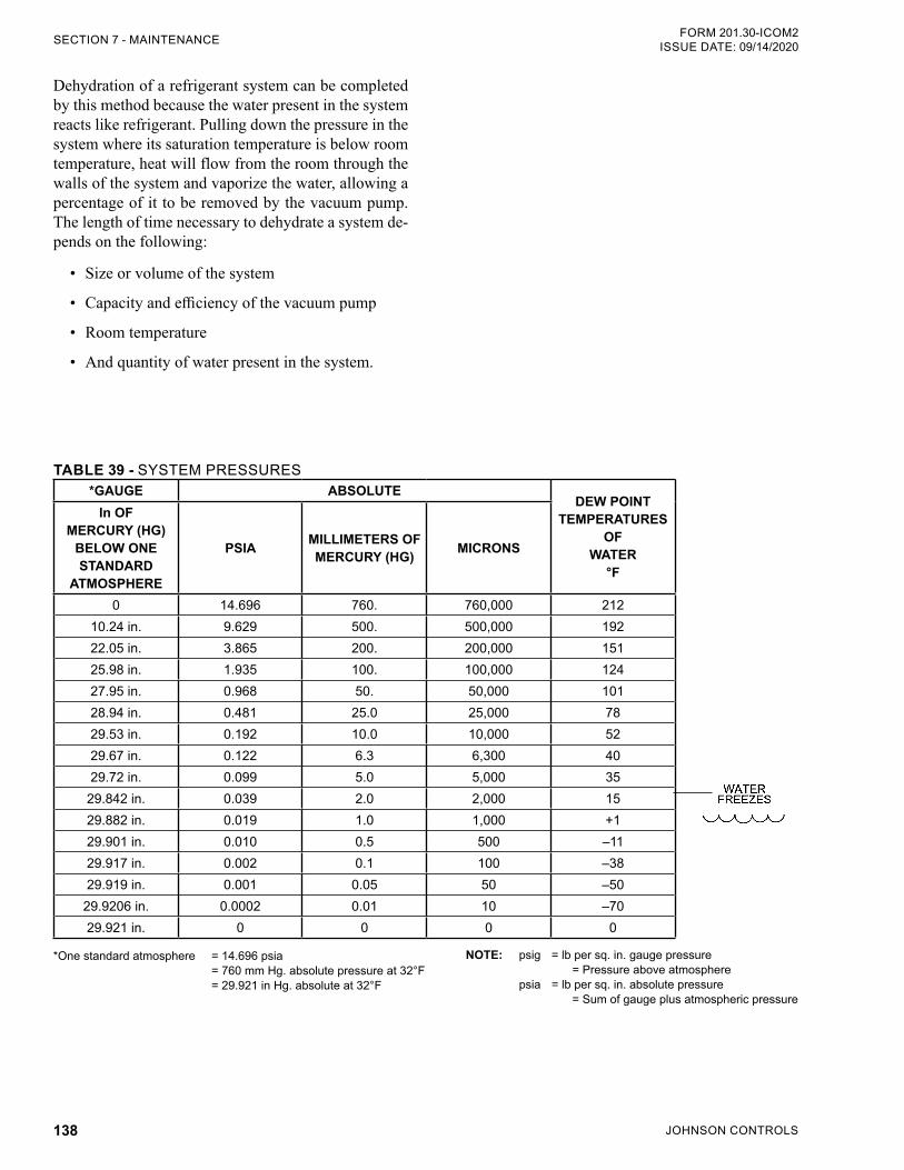
JOHNSON CONTROLS138
FORM 201.30-ICOM2ISSUE DATE: 09/14/2020SECTION 7 - MAINTENANCE
Dehydration of a refrigerant system can be completed by this method because the water present in the system reacts like refrigerant. Pulling down the pressure in the system where its saturation temperature is below room temperature, heat will flow from the room through the walls of the system and vaporize the water, allowing a percentage of it to be removed by the vacuum pump. The length of time necessary to dehydrate a system de-pends on the following:
• Size or volume of the system
• Capacity and efficiency of the vacuum pump
• Room temperature
• And quantity of water present in the system.
TABLE 39 - SYSTEM PRESSURES*GAUGE ABSOLUTE
DEW POINT TEMPERATURES
OF WATER
°F
In OF MERCURY (HG)
BELOW ONE STANDARD
ATMOSPHERE
PSIA MILLIMETERS OF MERCURY (HG) MICRONS
0 14.696 760. 760,000 21210.24 in. 9.629 500. 500,000 19222.05 in. 3.865 200. 200,000 15125.98 in. 1.935 100. 100,000 12427.95 in. 0.968 50. 50,000 10128.94 in. 0.481 25.0 25,000 7829.53 in. 0.192 10.0 10,000 5229.67 in. 0.122 6.3 6,300 4029.72 in. 0.099 5.0 5,000 35
29.842 in. 0.039 2.0 2,000 1529.882 in. 0.019 1.0 1,000 +129.901 in. 0.010 0.5 500 –1129.917 in. 0.002 0.1 100 –3829.919 in. 0.001 0.05 50 –50
29.9206 in. 0.0002 0.01 10 –7029.921 in. 0 0 0 0
*One standard atmosphere = 14.696 psia = 760 mm Hg. absolute pressure at 32°F = 29.921 in Hg. absolute at 32°F
NOTE: psig = lb per sq. in. gauge pressure = Pressure above atmosphere psia = lb per sq. in. absolute pressure = Sum of gauge plus atmospheric pressure
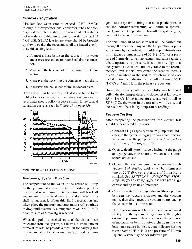
JOHNSON CONTROLS 139
SECTION 7 - MAINTENANCEFORM 201.30-ICOM2 ISSUE DATE: 09/14/2020
7
Improve DehydrationCirculate hot water (not to exceed 125°F (52°C)) through the evaporator and condenser tubes to thor-oughly dehydrate the shells. If a source of hot water is not readily available, use a portable water heater. DO NOT USE STEAM. A temperature should be brought up slowly so that the tubes and shell are heated evenly to avoid causing leaks.
1. Connect a hose between the source of hot water under pressure and evaporator head drain connec-tion.
2. Maneuver the hose out of the evaporator vent con-nection.
3. Maneuver the hose into the condenser head drain.
4. Maneuver the house out of the condenser vent.
If the system has been pressure tested and found to be tight before evacuation, then the saturation temperature recordings should follow a curve similar to the typical saturation curve as seen in Figure 69 on page 139.
FIGURE 69 - SATURATION CURVE
LD00474
Remaining System MoistureThe temperature of the water in the chiller will drop as the pressure decreases, until the boiling point is reached, at which point the temperature will level off and remain at this level until all of the water in the shell is vaporized. When this final vaporization has taken place the pressure and temperature will continue to drop until eventually a temperature of 35°F (1.6°C) or a pressure of 5 mm Hg is reached.
When this point is reached, most of the air has been evacuated from the system, but there is a small amount of moisture left. To provide a medium for carrying this residual moisture to the vacuum pump, introduce nitro-
gen into the system to bring it to atmospheric pressure and the indicator temperature will return to approxi-mately ambient temperature. Close off the system again, and start the second evacuation.
The small amount of moisture left will be carried out through the vacuum pump and the temperature or pres-sure shown by the indicator should drop uniformly un-til it reaches a temperature of 35°F (1.6°C) or a pres-sure of 5 mm Hg. When the vacuum indicator registers this temperature or pressure, it is a positive sign that the system is evacuated and dehydrated to the recom-mended limit. If this level cannot be reached, there is a leak somewhere in the system, which must be cor-rected before the indicator can be pulled down to 35°F (1.6°C) or 5 mm Hg in the primary evacuation.
During the primary pulldown, carefully watch the wet bulb indicator temperature, and do not let it fall below 35°F (1.6°C). If the temperature is allowed to fall to 32°F (0°C), the water in the test tube will freeze, and the result will be a faulty temperature reading.
Vacuum TestingAfter completing the pressure test, the vacuum test should be conducted as follows:
1. Connect a high capacity vacuum pump, with indi-cator, to the system charging valve or shell service valve and start the pump. See Evacuation and De-hydration of Unit on page 137.
2. Open wide all system valves, including the purge and gauge valves. Be sure all valves to the atmo-sphere are closed.
3. Operate the vacuum pump in accordance with Vacuum Dehydration until a wet bulb tempera-ture of 32°F (0°C) or a pressure of 5 mm Hg is reached. See SECTION 3 - HANDLING, STOR-AGE, INSTALLATION AND REASSEMBLY for corresponding values of pressure.
4. Close the system charging valve and the stop valve between the vacuum indicator and the vacuum pump, then disconnect the vacuum pump leaving the vacuum indicator in place.
5. Hold the vacuum wet bulb temperature obtained in Step 3 in the system for eight hours; the slight-est rise in pressure indicates a leak or the presence of moisture, or both. If, after eight hours the wet bulb temperature in the vacuum indicator has not risen above 40°F (4.4°C) or a pressure of 6.3 mm Hg, the system may be considered tight.
JOHNSON CONTROLS140
FORM 201.30-ICOM2ISSUE DATE: 09/14/2020SECTION 7 - MAINTENANCE
Be sure the vacuum indicator is valved off while holding the system vacuum. Open the valve between the vacuum indicator and the system when checking the vacuum after eight hours.
6. If the vacuum does not hold for eight hours within the limits specified in Step 5, find and repair the leak.
CONDENSERS AND EVAPORATORS MAINTENANCE
GeneralMaintenance of the condenser and evaporator shells is important to provide trouble free operation of the unit. The waterside of the shell tubes must be kept clean and free from scale. Proper maintenance, such as tube cleaning, is covered on the following pages.
Chemical Water TreatmentSince the mineral content of the water circulated through evaporators and condensers varies with almost every supply source, the water being used may corrode the tubes or deposit heat resistant scale in them.
Reliable water treatment companies are available in most large cities who can supply a water treating pro-cess, which will greatly reduce the corrosive and scale forming properties of almost any type of water.
As a preventive measure against scale and corrosion and to prolong the life of the evaporator and condenser tubes, a chemical analysis of the water should be made, before the system is installed. Consult a reliable water treatment company to determine if water treatment is necessary, and if so, to furnish the proper treatment for the particular water condition.
CLEANING EVAPORATOR AND CONDENSER TUBESThe condenser and evaporator tubes in a YVWA chiller are made of copper with mild carbon steel water boxes.
If the equipment is located in an unheated area susceptible to freezing, drain the wa-ter from the condenser and evaporator to prevent the tubes from freezing.
Condenser TubesProper condenser water treatment can eliminate or sig-nificantly reduce the formation of scale on the water-side of the condenser tubes.
Maintain a minimum condenser water flow rate through the tubes of at least 3.33 ft/s (1 m/s). Tube water veloc-ity should not exceed 12 ft/s (3.6 m/s).
Condenser tubes must be maintained to provide proper chiller operation. The condenser approach temperature, which is the difference between the condenser leaving water and the saturated condenser temperatures, is a useful tool to monitor the performance of the condens-er. Recording and logging the condenser approach tem-perature, as part of the chiller maintenance program, warns the operator that the waterside condenser tubes are fouled and require cleaning.
If the approach increases more than 4°F (2°C) above the approach when the tubes were clean, or during the annual condenser inspection the tubes are observed to be fouled, the tubes require cleaning.
In a condenser, a problem due to fouled tubes is usually indicated by:
• A steady rise in head pressure over a period of time
• A steady rise in condensing temperature
• Noisy operation
Tube FoulingFouling of the tubes can be due to two types of depos-its:
1. Rust or sludge – which finds its way into the tubes and accumulates there. This material usu-ally does not build up on the inner tube surfaces like scale, but does interfere with the heat transfer. Remove the rust or sludge from the tubes using a thorough brushing process.
2. Scale – due to mineral deposits. These deposits, although thin and scarcely detectable upon physi-cal inspection, are highly resistant to heat transfer. Remove the scale by circulating an acid solution through the tubes.
JOHNSON CONTROLS 141
SECTION 7 - MAINTENANCEFORM 201.30-ICOM2 ISSUE DATE: 09/14/2020
7
Non-condensable Gas Non-condensable gas that seeped into the chiller during incorrect evacuation or charging will also cause high condenser approach conditions. Purge the refrigerant vapor from the condenser into a refrigerant container to reveal non-condensable gas.
Evaporator TubesMaintain evaporator water or brine flow rates through the evaporator tubes for which the chiller was de-signed. Refer to the engineering data on the sales order form for the correct flow rates.
Generally, the water or brine that is circulated through the evaporator is part of a closed loop circuit that is treated with chemicals to prevent the formation of scale and debris.
The evaporator's lack of performance is indicated by cooling capacity decreases and the approach (tempera-ture difference between the water leaving the evapo-rator and the refrigerant temperature in the evapora-tor) increases. It is difficult to determine if the lack of performance is due to fouled tubes alone or due to a combination of problems, such as:
• Refrigerant leaks from the system.
• A shortage of refrigerant charge.
• An excessive quantity of oil in the evaporator.
Waterside Tube Cleaning Procedure Two methods are used for waterside tube cleaning to remove scale: chemical or mechanical. The scale com-position will determine which method is most effective to remove the scale and dirt.
Contact a Johnson Controls Field Service Office for a recommended method that is used locally.
Chemical Cleaning ProcedureAcid Cleaning of Tubes – If the tubes are fouled with a hard scale deposit, they may require acid cleaning. Before acid cleaning, clean the tubes by the brushing process described earlier. If the loose foreign material is removed before the acid cleaning, the acid solution will clean the tubes more efficiently, and in a shorter amount of time.
Chemical cleaning is an effective method to remove scale from internally enhanced copper tubes. However, a company knowledgeable with the chemical cleaning procedure should be contracted or consulted.
Follow the chemical cleaning company recommenda-tions concerning solution cleaning strength and time duration of the cleaning process.
Commercial Acid Cleaning – If acid cleaning is re-quired, Johnson Controls recommends using a com-mercial organization that offers a special service to acid clean evaporators and condensers, such as the Dow Industries Service Division, Dow Chemical Co., Tulsa, OK, which has branches in principal cities.
Serious damage to the condenser tubes will result if the chemical cleaning pro-cedure is improperly applied.
When chemical cleaning of the tubes is required, cal-culate the internal volume of the waterside condenser tubes with the following equation to properly mix the correct concentration of cleaning solution.
Vol (gal) = [Nominal tube size (in.)] x 3.14 x shell length (ft) x number of tubes/77
Contact a Johnson Controls Field Service Office for the size and number of tubes.
Mechanical tube cleaning must always follow a chemical cleaning procedure.
Mechanical Tube Cleaning Procedure1. Drain the water from the condenser.
2. Remove the water boxes from both ends of the condenser with proper lifting equipment. Use caution not to damage the threads on the mount-ing studs that are welded to the tube sheet.
3. Select a tube cleaning brush for 5/8 in. ID copper condenser tubes. If tubes other than those with 5/8 in. ID are used, select a tube cleaning brush that is made for the tube size. Generally, brushes made of hard plastic or brass bristled wires are preferred for cleaning copper tubes. DO NOT use a steel bristle brush.
4. Attach the tube cleaning brush to the end of a cleaning machine or rod.
JOHNSON CONTROLS142
FORM 201.30-ICOM2ISSUE DATE: 09/14/2020SECTION 7 - MAINTENANCE
5. Flush the condenser with clean water to remove the debris.
6. Replace the water box gasket with a new gasket, and reassemble the water box onto the condenser.
COMPRESSOR MAINTENANCETo perform maintenance on the compressor assem-bly, complete the following:
1. Check the operation of the oil return system and change the dehydrator.
2. Check and change the oil, and oil filters.
3. Check the operation of the oil heater.
4. Observe the operation of the compressor.
Internal wearing of compressor parts could be a seri-ous problem caused by improper lubrication, brought about by restricted oil lines, passages, or dirty oil fil-ters. If the unit is shutting down on low oil pressure (LOP), change the oil filter element and examine it for foreign material. If foreign material is noticeable and the same conditions continue to stop the unit operation after a new filter element is installed, contact a Johnson Controls Field Service Office.
ELECTRICAL CONTROLSFor information covering the control center opera-tion, see SECTION 6 - OPERATION in this manual, and Field Connections and Control Wiring for YVWA Chiller (Form 201.30-PW2).
Checking VSD Coolant LevelNever run the coolant pump without cool-ant! Running the coolant pump without coolant may damage the pump seals.
Always fill the system with approved YORK coolant to avoid damage to the pump seals and the chiller.
The chiller is shipped with a 50/50 mix of Propylene Glycol and YORK Corrosion Inhibitors. This type of coolant is being used to protect the cooling loop from damage due to freezing conditions during the shipping process. This coolant mixture does not have the ther-modynamic properties required by the variable speed drive, and must be removed. Drain the coolant from the variable speed drive.
This 50/50 mixture must be drained and replaced with YORK Corrosion Inhibitor as specified below.
1. Drain the coolant from the variable speed drive.
2. Fill the coolant loop using YORK’s Corrosion Inhibitor, part number 013-04129-000. Pour the solution into the top of the header pipe until the level is within a 1/2 in. of the top.
3. Then manually run the pump to remove pockets of air. Observe the level in the fill-pipe, and more coolant as necessary to bring the level back to ap-proximately 1/2 in. from the top of the pipe.
4. Continue to run the pump manually for 15 min-utes, adding more coolant as needed. Then rein-stall the pipe plug in the header pipe using teflon tape to ensure coolant does not evaporate through the pipe threads. Do not wrap the threads with more than 2 wraps of Teflon tape. Too much tape can cause the fill pipe to crack.
5. Remove the cap on the fill tube and run the cool-ant pump to verify the level in the fill tube.
6. Make sure the coolant level in the VSD cooling system is 1/2 in. (2 cm) from the top of the fill tube while running.
7. Run the pump by placing the chiller in SERVICE mode. See SECTION 6 - OPERATION.
8. Add new coolant, if necessary.
9. Reinstall the cap before stopping the coolant pump to avoid overflowing the fill tube when the coolant pump is turned off. The coolant system holds about 2 gal (7.6 L) of coolant.
Preventive MaintenanceIt is the owner's responsibility to fulfill the necessary daily, monthly and yearly system maintenance require-ments to keep the unit operating at its peak efficiency. Follow the maintenance schedule in Table 37 on page 129.
If a unit fails due to improper mainte-nance during the warranty period, John-son Controls will NOT be liable for costs incurred to return the system to satisfac-tory operation.
JOHNSON CONTROLS 143
FORM 201.30-ICOM2 ISSUE DATE: 09/14/2020
8
SECTION 8 - TROUBLESHOOTING
Successful troubleshooting requires an organized ap-proach to define the problem, identify the cause, and make the proper corrections. Sometimes two relatively obvious problems combine to provide a set of symp-toms that can mislead the troubleshooter. Be aware of this possibility and avoid repairs that do not solve the problems. See Table 40 page 144 for specific trouble-shooting information.
ABNORMAL OPERATION, ANALYSIS AND CORRECTIONUse the following steps to analyze an operational prob-lem effectively and make the necessary corrections:
1. Define the problem and its limits.
2. Identify all possible causes.
3. Test each cause until the source of the problem is found.
4. Make the necessary corrections.
When an operating problem develops, compare all op-erating information on the OPERATING DISPLAY key with normal operating conditions. If an operating log has been maintained, the log can help determine what constitutes normal operation for the compressor unit in that particular system.
TROUBLESHOOTING THE COMPRESSOR AND OIL SEPARATION SYSTEMTroubleshooting the compressor is limited to identi-fying the probable cause. If a mechanical problem is suspected, contact the Johnson Controls Field Service Office. DO NOT DISASSEMBLE THE COMPRES-SOR.
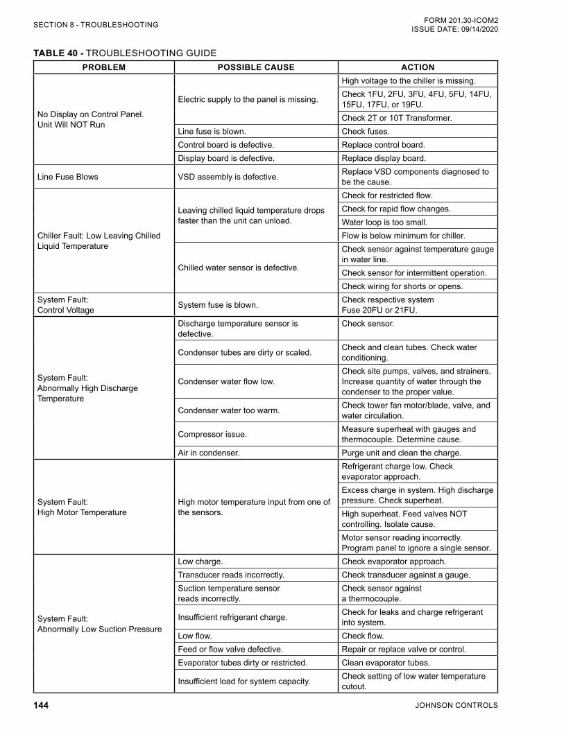
JOHNSON CONTROLS144
FORM 201.30-ICOM2ISSUE DATE: 09/14/2020SECTION 8 - TROUBLESHOOTING
TABLE 40 - TROUBLESHOOTING GUIDEPROBLEM POSSIBLE CAUSE ACTION
No Display on Control Panel.Unit Will NOT Run
Electric supply to the panel is missing.
High voltage to the chiller is missing.Check 1FU, 2FU, 3FU, 4FU, 5FU, 14FU, 15FU, 17FU, or 19FU.Check 2T or 10T Transformer.
Line fuse is blown. Check fuses.Control board is defective. Replace control board.Display board is defective. Replace display board.
Line Fuse Blows VSD assembly is defective. Replace VSD components diagnosed to be the cause.
Chiller Fault: Low Leaving Chilled Liquid Temperature
Leaving chilled liquid temperature drops faster than the unit can unload.
Check for restricted flow.Check for rapid flow changes.Water loop is too small.Flow is below minimum for chiller.
Chilled water sensor is defective.
Check sensor against temperature gauge in water line.Check sensor for intermittent operation.Check wiring for shorts or opens.
System Fault:Control Voltage System fuse is blown. Check respective system
Fuse 20FU or 21FU.
System Fault: Abnormally High Discharge Temperature
Discharge temperature sensor is defective.
Check sensor.
Condenser tubes are dirty or scaled. Check and clean tubes. Check water conditioning.
Condenser water flow low.Check site pumps, valves, and strainers. Increase quantity of water through the condenser to the proper value.
Condenser water too warm. Check tower fan motor/blade, valve, and water circulation.
Compressor issue. Measure superheat with gauges and thermocouple. Determine cause.
Air in condenser. Purge unit and clean the charge.
System Fault: High Motor Temperature
High motor temperature input from one of the sensors.
Refrigerant charge low. Check evaporator approach.Excess charge in system. High discharge pressure. Check superheat.High superheat. Feed valves NOT controlling. Isolate cause.Motor sensor reading incorrectly. Program panel to ignore a single sensor.
System Fault: Abnormally Low Suction Pressure
Low charge. Check evaporator approach.Transducer reads incorrectly. Check transducer against a gauge.Suction temperature sensor reads incorrectly.
Check sensor againsta thermocouple.
Insufficient refrigerant charge. Check for leaks and charge refrigerant into system.
Low flow. Check flow.Feed or flow valve defective. Repair or replace valve or control.Evaporator tubes dirty or restricted. Clean evaporator tubes.
Insufficient load for system capacity. Check setting of low water temperature cutout.
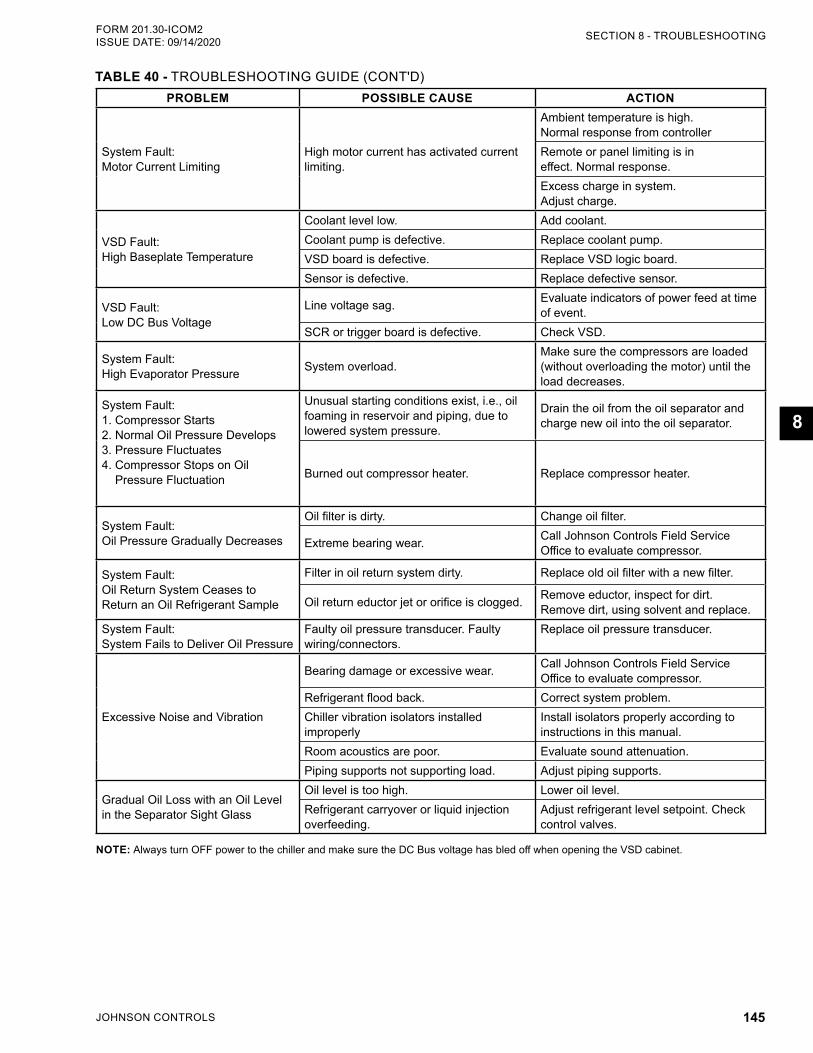
JOHNSON CONTROLS 145
SECTION 8 - TROUBLESHOOTINGFORM 201.30-ICOM2 ISSUE DATE: 09/14/2020
8
PROBLEM POSSIBLE CAUSE ACTION
System Fault:Motor Current Limiting
High motor current has activated current limiting.
Ambient temperature is high.Normal response from controllerRemote or panel limiting is in effect. Normal response.Excess charge in system.Adjust charge.
VSD Fault:High Baseplate Temperature
Coolant level low. Add coolant.Coolant pump is defective. Replace coolant pump.VSD board is defective. Replace VSD logic board.Sensor is defective. Replace defective sensor.
VSD Fault:Low DC Bus Voltage
Line voltage sag. Evaluate indicators of power feed at time of event.
SCR or trigger board is defective. Check VSD.
System Fault: High Evaporator Pressure System overload.
Make sure the compressors are loaded (without overloading the motor) until the load decreases.
System Fault:1. Compressor Starts2. Normal Oil Pressure Develops3. Pressure Fluctuates4. Compressor Stops on Oil
Pressure Fluctuation
Unusual starting conditions exist, i.e., oil foaming in reservoir and piping, due to lowered system pressure.
Drain the oil from the oil separator and charge new oil into the oil separator.
Burned out compressor heater. Replace compressor heater.
System Fault:Oil Pressure Gradually Decreases
Oil filter is dirty. Change oil filter.
Extreme bearing wear. Call Johnson Controls Field Service Office to evaluate compressor.
System Fault:Oil Return System Ceases to Return an Oil Refrigerant Sample
Filter in oil return system dirty. Replace old oil filter with a new filter.
Oil return eductor jet or orifice is clogged. Remove eductor, inspect for dirt. Remove dirt, using solvent and replace.
System Fault:System Fails to Deliver Oil Pressure
Faulty oil pressure transducer. Faulty wiring/connectors.
Replace oil pressure transducer.
Excessive Noise and Vibration
Bearing damage or excessive wear. Call Johnson Controls Field Service Office to evaluate compressor.
Refrigerant flood back. Correct system problem.Chiller vibration isolators installed improperly
Install isolators properly according to instructions in this manual.
Room acoustics are poor. Evaluate sound attenuation.Piping supports not supporting load. Adjust piping supports.
Gradual Oil Loss with an Oil Level in the Separator Sight Glass
Oil level is too high. Lower oil level.Refrigerant carryover or liquid injection overfeeding.
Adjust refrigerant level setpoint. Check control valves.
NOTE: Always turn OFF power to the chiller and make sure the DC Bus voltage has bled off when opening the VSD cabinet.
TABLE 40 - TROUBLESHOOTING GUIDE (CONT'D)
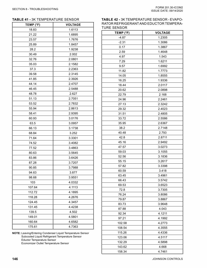
JOHNSON CONTROLS146
FORM 201.30-ICOM2ISSUE DATE: 09/14/2020SECTION 8 - TROUBLESHOOTING
TABLE 41 - 3K TEMPERATURE SENSORTEMP (°F) VOLTAGE
18.83 1.611321.22 1.689523.57 1.767625.89 1.845728.2 1.9238
30.49 2.00232.76 2.080135.03 2.158237.3 2.2363
39.58 2.314541.85 2.392644.14 2.470746.45 2.548848.78 2.62751.13 2.705153.52 2.783255.94 2.861358.41 2.939560.93 3.017663.5 3.0957
66.13 3.173868.84 3.25271.64 3.330174.52 3.408277.52 3.486380.63 3.564583.86 3.642687.28 3.720790.85 3.798894.63 3.87798.68 3.9551103 4.0332
107.64 4.1113112.72 4.1895118.28 4.2676124.45 4.3457131.45 4.4238139.5 4.502
149.01 4.5801160.64 4.6582175.61 4.7363
NOTE: Leaving/Entering Condenser Liquid Temperature Sensor Subcooled Liquid Refrigerant Temperature Sensor Eductor Temperature Sensor Economizer Outlet Temperature Sensor
TABLE 42 - 3K TEMPERATURE SENSOR - EVAPO-RATOR REFRIGERANT AND EDUCTOR TEMPERA-TURE SENSOR
TEMP (°F) VOLTAGE -4.87 1.2305-2.31 1.30860.17 1.38672.59 1.46484.97 1.5437.29 1.62119.57 1.699211.82 1.777314.05 1.855516.25 1.933618.44 2.011720.62 2.089822.79 2.16824.96 2.246127.13 2.324229.32 2.402331.51 2.480533.72 2.558635.95 2.636738.2 2.7148
40.48 2.79342.8 2.8711
45.16 2.949247.57 3.027359.03 3.105552.56 3.183655.15 3.261757.82 3.339860.59 3.41863.45 3.496166.43 3.574269.53 3.652372.8 3.7305
76.24 3.808679.87 3.886783.73 3.964887.88 4.04392.34 4.121197.21 4.1992
102.58 4.2773108.54 4.3555115.26 4.4336123.06 4.5117132.29 4.5898143.62 4.668158.34 4.7461
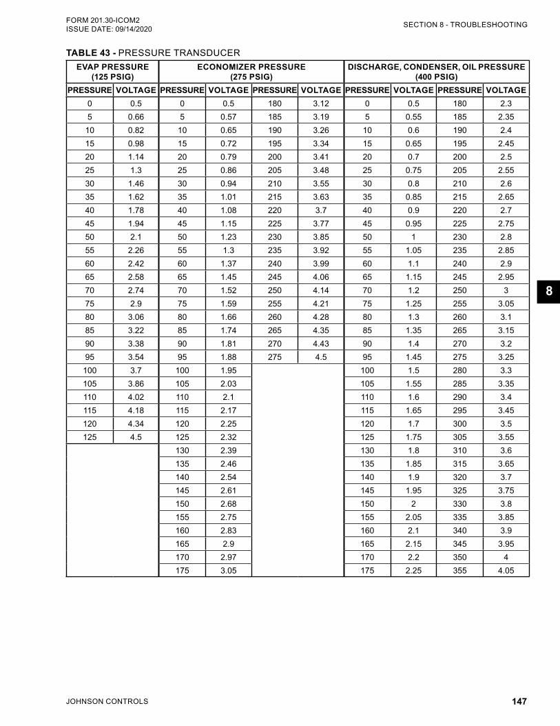
JOHNSON CONTROLS 147
SECTION 8 - TROUBLESHOOTINGFORM 201.30-ICOM2 ISSUE DATE: 09/14/2020
8
TABLE 43 - PRESSURE TRANSDUCEREVAP PRESSURE
(125 PSIG)ECONOMIZER PRESSURE
(275 PSIG)DISCHARGE, CONDENSER, OIL PRESSURE
(400 PSIG)PRESSURE VOLTAGE PRESSURE VOLTAGE PRESSURE VOLTAGE PRESSURE VOLTAGE PRESSURE VOLTAGE
0 0.5 0 0.5 180 3.12 0 0.5 180 2.35 0.66 5 0.57 185 3.19 5 0.55 185 2.35
10 0.82 10 0.65 190 3.26 10 0.6 190 2.415 0.98 15 0.72 195 3.34 15 0.65 195 2.4520 1.14 20 0.79 200 3.41 20 0.7 200 2.525 1.3 25 0.86 205 3.48 25 0.75 205 2.5530 1.46 30 0.94 210 3.55 30 0.8 210 2.635 1.62 35 1.01 215 3.63 35 0.85 215 2.6540 1.78 40 1.08 220 3.7 40 0.9 220 2.745 1.94 45 1.15 225 3.77 45 0.95 225 2.7550 2.1 50 1.23 230 3.85 50 1 230 2.855 2.26 55 1.3 235 3.92 55 1.05 235 2.8560 2.42 60 1.37 240 3.99 60 1.1 240 2.965 2.58 65 1.45 245 4.06 65 1.15 245 2.9570 2.74 70 1.52 250 4.14 70 1.2 250 375 2.9 75 1.59 255 4.21 75 1.25 255 3.0580 3.06 80 1.66 260 4.28 80 1.3 260 3.185 3.22 85 1.74 265 4.35 85 1.35 265 3.1590 3.38 90 1.81 270 4.43 90 1.4 270 3.295 3.54 95 1.88 275 4.5 95 1.45 275 3.25
100 3.7 100 1.95 100 1.5 280 3.3105 3.86 105 2.03 105 1.55 285 3.35110 4.02 110 2.1 110 1.6 290 3.4115 4.18 115 2.17 115 1.65 295 3.45120 4.34 120 2.25 120 1.7 300 3.5125 4.5 125 2.32 125 1.75 305 3.55
130 2.39 130 1.8 310 3.6135 2.46 135 1.85 315 3.65140 2.54 140 1.9 320 3.7145 2.61 145 1.95 325 3.75150 2.68 150 2 330 3.8155 2.75 155 2.05 335 3.85160 2.83 160 2.1 340 3.9165 2.9 165 2.15 345 3.95170 2.97 170 2.2 350 4175 3.05 175 2.25 355 4.05

JOHNSON CONTROLS148
FORM 201.30-ICOM2ISSUE DATE: 09/14/2020
THIS PAGE INTENTIONALLY LEFT BLANK.
JOHNSON CONTROLS 149
FORM 201.30-ICOM2 ISSUE DATE: 09/14/2020
9
SECTION 9 - DECOMMISSIONING, DISMANTLING, AND DISPOSAL
Never release refrigerant to the atmo-sphere when emptying the refrigerating circuits. Suitable retrieval equipment must be used. If reclaimed refrigerant cannot be reused, it must be returned to the manufacturer.
Never discard used compressor oil, as it contains refrigerant in solution. Return used oil to the oil manufacturer.
Unless otherwise indicated, the operations described below can be performed by any properly trained main-tenance technician.
1. Isolate all sources of electrical supply to the unit, including any control system supplies switched by the unit. Make sure that all points of isolation are secured in the off position.
2. Disconnect and remove the supply cables. For connection points, see SECTION 3 - HANDLING, STORAGE, INSTALLATION AND REASSEM-BLY.
3. Remove all refrigerant from each system into a suitable container, using a refrigerant reclaim or recovery unit. This refrigerant may then be reused, if appropriate, or returned to the manufacturer for disposal. Under NO circumstances should refrig-erant be vented to the atmosphere.
4. Drain the refrigerant oil from each system into a suitable container and dispose of according to lo-cal laws and regulations. Any spilled oil should be mopped up and similarly disposed of.
5. Isolate the unit heat exchanger from the external water systems and drain the heat exchanger sec-tion of the system. If no isolation valves are in-stalled it may be necessary to drain the complete system.
6. If glycol was used in the water system, or chemi-cal additives are contained, dispose of the solu-tion in a suitable and safe manner. Under NO cir-cumstances should any system containing glycol be drained directly into domestic waste or natural water systems.
7. After draining, disconnect and remove the water.
8. Remove the packaged units in one piece after dis-connecting the unit. Remove fixing down bolts, and then lift the unit from position, using the points provided and equipment with adequate lift-ing capacity.
See SECTION 3 - HANDLING, STORAGE, INSTAL-LATION AND REASSEMBLY for unit installation in-structions, and SECTION 7 - MAINTENANCE for unit weights.
Units, which cannot be removed in one piece after dis-connection, must be dismantled in position. Handle each component carefully. Where possible, dismantle units in the reverse order of installation.
Make sure that while components are being removed, the remaining parts are supported in a safe manner.
Only use lifting equipment of adequate capacity.
After removing the unit from position, dispose the unit parts according to local laws and regulations.
JOHNSON CONTROLS150
FORM 201.30-ICOM2ISSUE DATE: 09/14/2020
NOTES
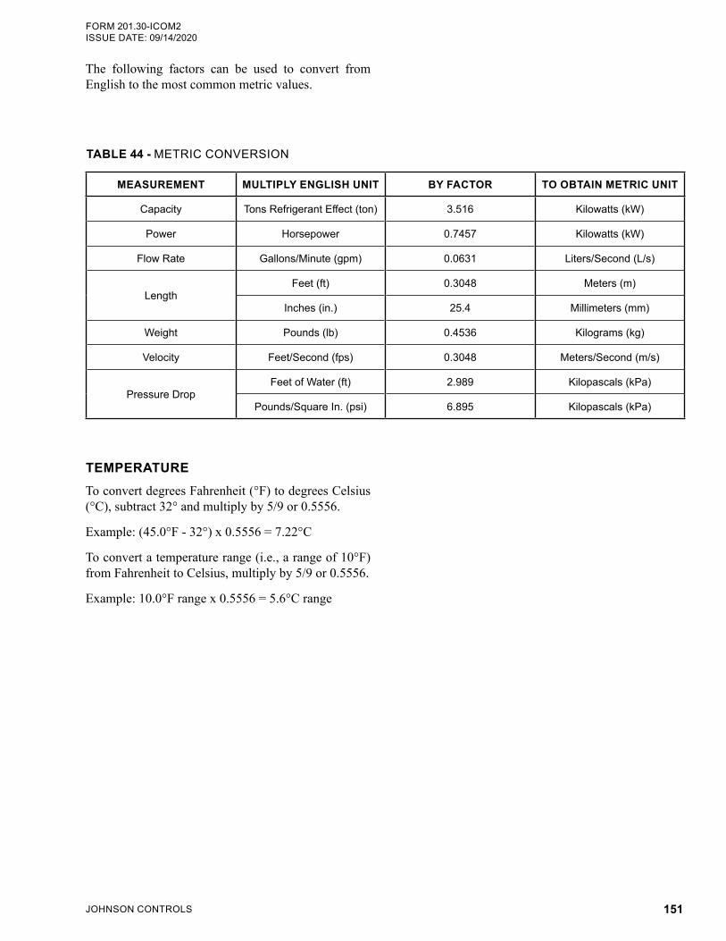
JOHNSON CONTROLS 151
FORM 201.30-ICOM2 ISSUE DATE: 09/14/2020
The following factors can be used to convert from English to the most common metric values.
TEMPERATURETo convert degrees Fahrenheit (°F) to degrees Celsius (°C), subtract 32° and multiply by 5/9 or 0.5556.
Example: (45.0°F - 32°) x 0.5556 = 7.22°C
To convert a temperature range (i.e., a range of 10°F) from Fahrenheit to Celsius, multiply by 5/9 or 0.5556.
Example: 10.0°F range x 0.5556 = 5.6°C range
TABLE 44 - METRIC CONVERSION
MEASUREMENT MULTIPLY ENGLISH UNIT BY FACTOR TO OBTAIN METRIC UNIT
Capacity Tons Refrigerant Effect (ton) 3.516 Kilowatts (kW)
Power Horsepower 0.7457 Kilowatts (kW)
Flow Rate Gallons/Minute (gpm) 0.0631 Liters/Second (L/s)
LengthFeet (ft) 0.3048 Meters (m)
Inches (in.) 25.4 Millimeters (mm)
Weight Pounds (lb) 0.4536 Kilograms (kg)
Velocity Feet/Second (fps) 0.3048 Meters/Second (m/s)
Pressure DropFeet of Water (ft) 2.989 Kilopascals (kPa)
Pounds/Square In. (psi) 6.895 Kilopascals (kPa)

5000 Renaissance Drive, New Freedom, Pennsylvania USA 17349 Subject to change without notice. Printed in USACopyright © by Johnson Controls 2020 ALL RIGHTS RESERVEDForm 201.30-ICOM2 (920)Issue Date: September 14, 2020 Supersedes: 201.30-ICOM2 (320)
1-800-524-1330www.johnsoncontrols.com