Embed Size (px)
Citation preview
808 B – 07/11 A – pag. 1/52
Product Manual 511 B – 08/10 A
Date: October 2008
Supersedes: None
Inverter Air cooled screw chillers
McEnergy Inverter
SSE (Standard Seasonal Efficiency) – XSE (High Seasonal Efficiency) 094.2÷147.2
Cooling capacity from 329 to 515 kW
Refrigerant: R-134a
McQuay is participating in the Eurovent Certification Programme. Product are as listed in the Eurovent Directory of Certified Products
and on the web site www .eurovent-certification. com
808 B – 07/11 A – pag. 2/52
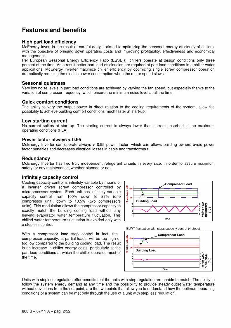
ELWT fluctuation with steps capacity control (4 steps)
NO EWLT fluctuation with McQuay stepless capacity control (4 steps)
Features and benefits
High part load efficiency McEnergy Invert is the result of careful design, aimed to optimizing the seasonal energy efficiency of chillers, with the objective of bringing down operating costs and improving profitability, effectiveness and economical management. Per European Seasonal Energy Efficiency Ratio (ESSER), chillers operate at design conditions only three percent of the time. As a result better part load efficiencies are required at part load conditions in a chiller water applications. McEnergy Inverter maximize chiller efficiency by optimizing single screw compressor operation dramatically reducing the electric power consumption when the motor speed slows.
Seasonal quietness Very low noise levels in part load conditions are achieved by varying the fan speed, but especially thanks to the variation of compressor frequency, which ensure the minimum noise level at all the time.
Quick comfort conditions The ability to vary the output power in direct relation to the cooling requirements of the system, allow the possibility to achieve building comfort conditions much faster at start-up.
Low starting current No current spikes at start-up. The starting current is always lower than current absorbed in the maximum operating conditions (FLA).
Power factor always > 0.95 McEnergy Inverter can operate always > 0.95 power factor, which can allows building owners avoid power factor penalties and decreases electrical losses in cable and transformers.
Redundancy McEnergy Inverter has two truly independent refrigerant circuits in every size, in order to assure maximum safety for any maintenance, whether planned or not.
Infinitely capacity control Cooling capacity control is infinitely variable by means of
a Inverter driven screw compressor controlled by
microprocessor system. Each unit has infinitely variable
capacity control from 100% down to 27% (one
compressor unit), down to 13,5% (two compressors
units). This modulation allows the compressor capacity to
exactly match the building cooling load without any
leaving evaporator water temperature fluctuation. This
chilled water temperature fluctuation is avoided only with
a stepless control.
With a compressor load step control in fact, the
compressor capacity, at partial loads, will be too high or
too low compared to the building cooling load. The result
is an increase in chiller energy costs, particularly at the
part-load conditions at which the chiller operates most of
the time. Units with stepless regulation offer benefits that the units with step regulation are unable to match. The ability to follow the system energy demand at any time and the possibility to provide steady outlet water temperature without deviations from the set-point, are the two points that allow you to understand how the optimum operating conditions of a system can be met only through the use of a unit with step-less regulation.
time
Compressor Load
Building Load
Building Load
Compressor Load
808 B – 07/11 A – pag. 3/52
Code requirements – Safety and observant of laws/directives All water cooled units are designed and manufactured in accordance with applicable selections of the following which are equivalent to American Air-conditioning industry applicable codes:
Rating of chillers EN 12055
Construction of pressure vessel Pressure Equipment 97/23/EC (PED)
Machinery Directive 98/37/EC
Low Voltage 2006/95/EC
Electromagnetic Compatibility 2004/108/EC
Electrical & Safety codes IEC 60204–1
Manufacturing Quality Stds UNI – EN ISO 9001:2000
Certifications All units manufactured by McQuay Italia S.p.A. are CE marked, complying with European directives in force, concerning manufacturing and safety. On request units can be produced complying with laws in force in non European countries (ASME, GOST, etc.), and with other applications, such as naval (RINA, etc.).
Versions McEnergy Inverter is available in two different Seasonal Efficiency Versions:
SSE: Standard Seasonal Efficiency 7 sizes to cover a range from 329 up to 515 kW with an ESEER up to 4.62
XSE: High Seasonal Efficiency
7 sizes to cover a range from 329 up to 515 kW with an ESEER up to 5.01 The ESEER (European Seasonal Energy Efficiency Ratio) is a weighed formula enabling to take into account the variation of EER with the load rate and the variation of air inlet condenser temperature. ESEER = A x EER100% + B x EER75% + C x EER50% + D x EER25%
A B C D
Coefficient 0.03 (3%) 0.33 (33%) 0.41 (41%) 0.23 (23%)
Air inlet condenser temperature 35°C 30°C 25°C 20°C
Noise Configuration McEnergy Inverter is available in many different Noise level configurations:
ST: Standard Noise Condenser fan rotating at 700 rpm, rubber antivibration on compressor
LN: Low Noise
Condenser fan rotating at 700 rpm, rubber antivibration on compressor, sound proof cabinet for each compressor
XN: Extra Low Noise (available only for XSE version)
Condenser fan rotating at 700 rpm, rubber antivibration on compressor, one sound proof cabinet for compressor and evaporator, suction muffler
808 B – 07/11 A – pag. 4/52
General characteristics
Cabinet and structure The cabinet is made of galvanized steel sheet and painted to provide a high resistance to corrosion. The base
frame has rings for lifting the unit with ropes for an easy installation. The weight is uniformly distributed along
the profiles of the base and this facilitates the arrangement of the unit.
Screw compressors with integrated oil separator The compressors are semi-hermetic, single-screw type with gate-rotor (made of carbon impregnated engineered composite material). Each compressor has one inverter managed by the unit microprocessor for infinitely modulating the capacity. An integrated high efficiency oil separator maximises the oil separation.
Start is inverter type.
Ecological HFC 134a refrigerant The compressors have been designed to operate with R-134a, ecological refrigerant with zero ODP (Ozone
Depletion Potential) and very low GWP (Global Warming Potential) that means low TEWI (Total Equivalent
Warming Impact).
Evaporator The units are supplied with optimised shell and tubes evaporator pass that allows a perfect oil circulation and so
a perfect oil return to the compressor. It is direct expansion with refrigerant inside the tubes and water outside
(shell side) with carbon steel tube sheets, with straight copper tubes that are spirally wound internally for higher
efficiencies, expanded on the tube plates. The external shell is covered with a 10mm closed cell insulation
material. Each evaporator has 2 circuits, one for each compressor and is manufactured in accordance to PED
approval. The evaporator water outlet connections are provided with Victaulic Kit.
Condenser coils The condenser is manufactured with internally enhanced seamless copper tubes arranged in a staggered row
pattern and mechanically expanded into McQuay lanced and rippled aluminium condenser fins with full fin
collars. An integral sub-cooler circuit provides sub-cooling to effectively eliminate liquid flashing and increase in
cooling capacity without increasing the power input.
Condenser coil fans The condenser fans are helical type with wing-profile blades for achieving better performance. Each fan is
protected by a guard. The motors are IP54. Fans thermal overload relays are supplied as standard.
Electronic expansion valve The unit is equipped with the most advanced electronic expansion valves to achieve precise control of
refrigerant mass flow. As today’s system requires improved energy efficiency, tighter temperature control, wider
range of operating conditions and incorporate features like remote monitoring and diagnostics, the application of
electronic expansion valves becomes mandatory. Electronic expansion valve proposes features that makes it
unique: short opening and closing time, high resolution, positive shut-off function to eliminate use of additional
solenoid valve, highly linear flow capacity, continuous modulation of mass flow without stress in the refrigerant
circuit and corrosion resistance stainless steel body.
EEXV strength point is the capacity to work with lower ∆P between high and low pressure side, than a thermostatic expansion valve. The electronic expansion valve allows the system to work with low condenser pressure (winter time) without any refrigerant flow problems and with a perfect chilled water leaving temperature control.
Refrigerant Circuit Each unit has 2 independent refrigerant circuits and each one includes:
• Compressor with integrated oil separator
• Oil pressure transducer
• High and pressure switches
• High pressure transducer
• Low pressure transducer
• Moisture liquid indicator
• High efficiency oil separator
• Replaceable core filter-drier
808 B – 07/11 A – pag. 5/52
• Electronic expansion valve
• Suction line shut off valve
• Discharge line shut off valve
Electrical control panel Power and control are located in two sections of the main panel that is manufactured to ensure protection
against all weather conditions. The power panel is fitted with an interlocked door main isolator to prevent access
while power supply is on. Electrical panel is IP54.
Power Section The power section includes circuit breaker, compressors inverters, fans contactors, fans thermal overload
relays, fans inverter and control circuit transformer.
MicroTech II C Plus controller MicroTech II C Plus controller is installed as standard; it can be used to modify unit set-points and check control
parameters. A built-in display shows machine's operating status, programmable values, set-points, like
temperatures and pressures of water, refrigerant and air. Device controls maximise the chiller energy efficiency
and the reliability. A sophisticated software with predictive logic, select the most energy efficient combination of
compressors, EEXV and condenser fans to keep stable operating conditions and maximise energy efficiency.
The compressors are automatically rotated to ensure equal operating hours. MicroTech II C Plus protects critical
components in response to external signals from its system sensors measuring: motor temperatures, refrigerant
gas and oil pressures, correct phase sequence and evaporator.
Control section - main features
• Management of the compressor capacity, Inverter, slide and fans modulation.
• Chillers enabled to work in partial failure condition.
• Full routine operation at condition of:
- high ambient temperature value,
- high thermal load,
- high evaporator entering water temperature (start-up).
• Display of evaporator entering/leaving water temperature.
• Display of condensing-evaporating temperature and pressure, suction and discharge superheat for each
circuit.
• Leaving water cooled temperature regulation. Temperature tolerance = 0,1°C.
• Compressors and evaporator pumps hours counter.
• Display of Status Safety Devices.
• Start up numbers and compressors working hours equalization.
• Optimized management of compressors load.
• Fans management according to condensing pressure.
• Automatic re-start in case of power supply interruption (adjustable).
• Soft Load.
• Start at high evaporator water temperature.
• Return Reset.
• AOT Reset (optional).
• Set point Reset (optional).
Safety for each refrigerant circuit
• High pressure (pressure switch).
• Low pressure (transducer).
• Condensation fan Magneto-thermal.
• High Discharge Temperature on the compressor.
• Phase Monitor.
• Low pressure ratio.
808 B – 07/11 A – pag. 6/52
• High oil pressure drop.
• Low oil pressure.
System security
• Phase monitor.
• Freeze protection.
Regulation type Proportional + integral + derivative regulation on the leaving water evaporator output probe.
Condensation The condensation can be carried out according to temperature or pressure or pressure ratio. The fans can be
managed according to a 0/10 V modulating signal.
Intelligent Compressor Start Mode Control software includes an intelligent compressor start mode that unloads the first compressor to 75% during
the start of the second one, in order to reduce inrush current.
MicroTech II C Plus terminal
MicroTech II C Plus built-in terminal has the following features.
• 4-lines by 20-character liquid crystal display back lighting.
• Key-pad consisting of 6 keys.
• Memory to protect the data.
• General faults alarm relays.
• Password access to modify the setting.
• Service report displaying all running hours and general conditions.
• Alarm history memory to allow an easy fault analysis.
Standard accessories (supplied on basic unit)
Double set-point – Dual leaving water temperature set-points.
Fans thermal overload relays – Safety devices against fan motor overloading in addition to the normal
protection envisaged by the electrical windings.
Phase monitor – The phase monitor controls that phases sequence is correct and controls phase loss.
Inverter starter – For low inrush current and reduced starting torque.
Victaulic evaporator water connection – Hydraulic joint with gasket for an easy and quick water connection.
Evaporator electric heater – Electric heater controlled by a thermostat to protect the evaporator from freezing
down to -28°C ambient temperature, providing the power supply is on.
Electronic Expansion Valve.
Discharge line shut off valves – Installed on the discharge port of the compressor.
Suction line shut off valve – Suction shut-off valve installed on the suction port of the compressor to facilitate
maintenance operation.
Low pressure manometers.
Hour run meter.
General fault relay – Contactor for alarm warning.
808 B – 07/11 A – pag. 7/52
Options (on request)
Total heat recovery – Produced with shell and tube heat exchangers to produce hot water up to +55° C. The
heat exchangers are mounted on the refrigerant circuits parallel to the condenser coils to remove all the
condensation heat.
Partial heat recovery – Produced with plate to plate heat exchangers installed between the compressor
discharge and the condenser coil. These allow hot water to be produced up to a maximum temperature of 55°C.
Brine version – Set-point can go down to -8°C.
20mm insulation on evaporator.
Condenser coil guards
Cu-Cu condensing coils - To give better protection against corrosion by aggressive environments.
Cu-Cu-Sn condensing coils - To give better protection against corrosion in aggressive environments and by
salty air.
Alucoat condensing coils - Fins are protected by a special acrylic paint with a high resistance to corrosion.
Hydronic Kit (one water circulation pump – low or high lift) – Hydronic kit consists of: one centrifugal pump
direct driven, expansion vessel water feed circuit with pressure gauge, safety valve. The pump motor is
protected by a circuit breaker installed in control panel. The kit is assembled and wired to the control panel.
Hydronic kit (two water circulation pumps – low or high lift) – Hydronic kit consists of: two centrifugal
pumps direct driven, expansion vessel, water feed circuit with pressure gauge, safety valve. The pumps motors
are protected by circuit breakers installed in control panel. The kit is assembled and wired to the control panel.
Under/Over Voltage – This device control the voltage value and stop the chiller when this exceeds limits set by
customer.
Current limit display
Evaporator Flow switch - Supplied separately to be wired and installed on the evaporator water piping (by the
customer).
High pressure manometers.
Set-point reset and demand limit and alarm from external device.
Ambient outside temperature sensor and set-point reset.
Rubber type antivibration mounts - Supplied separately, these are positioned under the base of the unit
during installation. Ideal to reduce the vibrations when the unit is floor mounted.
Spring type antivibration mounts - Supplied separately, these are positioned under the base of the unit
during installation. Ideal for dampening vibrations for installation on roofs and metallic structures.
Inertial tank with cabinet ( 500 l or 1000 l ) – Piping to unit are not included and electric heater power supply
has to be provided from external source.
Witness tests - Every unit is always tested at the test bench prior to the shipment. On request, a second test
can be carried out, at customer’s presence, in accordance with the procedures indicated on the test form. (Not
available for units with glycol mixtures).
Acoustic test.

808 B – 07/11 A – pag. 8/52
Supervising systems (on request)
PlantVisorTM: Solution for tele-maintenance and supervisory
MicroTech II C Plus can be monitored locally or via modem or GSM by PlantVisorTM
supervision program.
PlantVisorTM is compatible with all Windows based systems.
It allows the followings functions:
• Unit status monitoring
• Circuits status monitoring
• Set-points modification
• Alarms display.
MicroTech II C Plus remote control MicroTech II C Plus is able to communicate to BMS (Building Management System) based on the most
common protocols as:
• CARELNative
• ModbusRTU
• LonWorks, now also based on the international 8040 Standard Chiller Profile and LonMark Technology
• BacNet BTP certifief over IP and MS/TP (class 4)
• Ethernet TCP/IP and SNM.
Chiller Sequencing
MicroTech II control family allows an easy plug-in sequencing technology based on digital or serial field panel
MCS (McQuay Chiller Sequences)
Digital Step Inverter to sequence and rotate up to 11 chillers, based on 1 or 2 configurable input sensors. A very
interesting low level full configurable digital field system. Monitorable by Plant Visor.
CSC III (Chiller System Controller III)
Serial sequences for up to 6 chillers. Full featured field serial device to sequence, optimize and monitor a little
group of McQuay chillers. Monitorable by Plant Visor.
808 B – 07/11 A – pag. 9/52
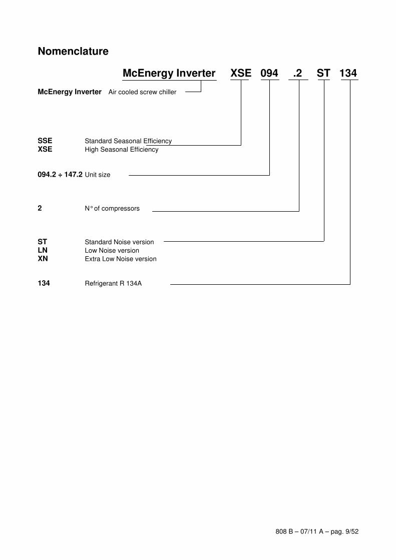
Nomenclature
McEnergy Inverter XSE 094 .2 ST 134 McEnergy Inverter Air cooled screw chiller
SSE Standard Seasonal Efficiency
XSE High Seasonal Efficiency 094.2 ÷ 147.2 Unit size
2 N° of compressors ST Standard Noise version
LN Low Noise version XN Extra Low Noise version
134 Refrigerant R 134A
808 B – 07/11 A – pag. 10/52
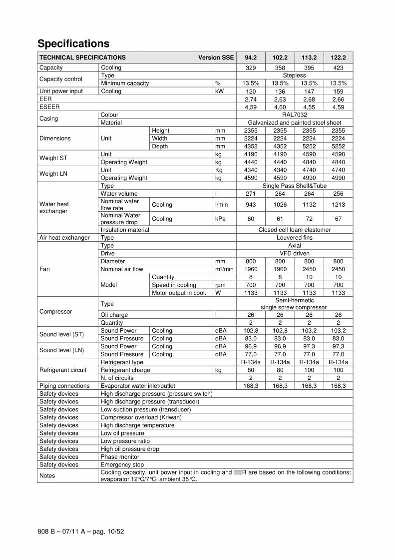
Specifications TECHNICAL SPECIFICATIONS Version SSE 94.2 102.2 113.2 122.2
Capacity Cooling 329 358 395 423
Type Stepless Capacity control
Minimum capacity % 13.5% 13.5% 13.5% 13.5%
Unit power input Cooling kW 120 136 147 159
EER 2,74 2,63 2,68 2,66
ESEER 4,59 4,60 4,55 4,59
Colour RAL7032 Casing
Material Galvanized and painted steel sheet
Height mm 2355 2355 2355 2355
Width mm 2224 2224 2224 2224 Dimensions Unit
Depth mm 4352 4352 5252 5252
Unit kg 4190 4190 4590 4590 Weight ST
Operating Weight kg 4440 4440 4840 4840
Unit Kg 4340 4340 4740 4740 Weight LN
Operating Weight kg 4590 4590 4990 4990
Type Single Pass Shell&Tube
Water volume l 271 264 264 256
Nominal water flow rate
Cooling l/min 943 1026 1132 1213
Nominal Water pressure drop
Cooling kPa 60 61 72 67
Water heat exchanger
Insulation material Closed cell foam elastomer
Air heat exchanger Type Louvered fins
Type Axial
Drive VFD driven
Diameter mm 800 800 800 800
Nominal air flow m³/min 1960 1960 2450 2450
Quantity 8 8 10 10
Speed in cooling rpm 700 700 700 700
Fan
Model
Motor output in cool. W 1133 1133 1133 1133
Type Semi-hermetic
single screw compressor
Oil charge l 26 26 26 26 Compressor
Quantity 2 2 2 2
Sound Power Cooling dBA 102,8 102,8 103,2 103,2 Sound level (ST)
Sound Pressure Cooling dBA 83,0 83,0 83,0 83,0
Sound Power Cooling dBA 96,9 96,9 97,3 97,3 Sound level (LN)
Sound Pressure Cooling dBA 77,0 77,0 77,0 77,0
Refrigerant type R-134a R-134a R-134a R-134a
Refrigerant charge kg 80 80 100 100 Refrigerant circuit
N. of circuits 2 2 2 2
Piping connections Evaporator water inlet/outlet 168,3 168,3 168,3 168,3
Safety devices High discharge pressure (pressure switch)
Safety devices High discharge pressure (transducer)
Safety devices Low suction pressure (transducer)
Safety devices Compressor overload (Kriwan)
Safety devices High discharge temperature
Safety devices Low oil pressure
Safety devices Low pressure ratio
Safety devices High oil pressure drop
Safety devices Phase monitor
Safety devices Emergency stop
Notes Cooling capacity, unit power input in cooling and EER are based on the following conditions: evaporator 12°C/7°C; ambient 35°C.
808 B – 07/11 A – pag. 11/52
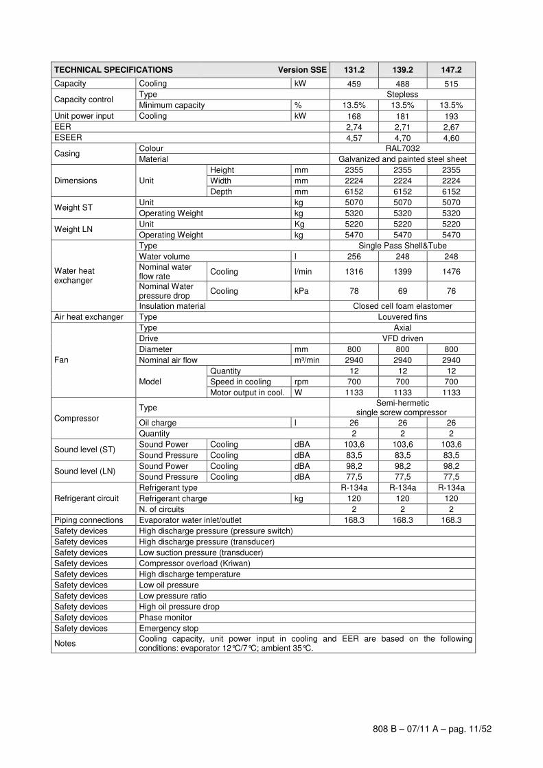
TECHNICAL SPECIFICATIONS Version SSE 131.2 139.2 147.2
Capacity Cooling kW 459 488 515
Type Stepless Capacity control
Minimum capacity % 13.5% 13.5% 13.5%
Unit power input Cooling kW 168 181 193
EER 2,74 2,71 2,67
ESEER 4,57 4,70 4,60
Colour RAL7032 Casing
Material Galvanized and painted steel sheet
Height mm 2355 2355 2355
Width mm 2224 2224 2224 Dimensions Unit
Depth mm 6152 6152 6152
Unit kg 5070 5070 5070 Weight ST
Operating Weight kg 5320 5320 5320
Unit Kg 5220 5220 5220 Weight LN
Operating Weight kg 5470 5470 5470
Type Single Pass Shell&Tube
Water volume l 256 248 248
Nominal water flow rate
Cooling l/min 1316 1399 1476
Nominal Water pressure drop
Cooling kPa 78 69 76
Water heat exchanger
Insulation material Closed cell foam elastomer
Air heat exchanger Type Louvered fins
Type Axial
Drive VFD driven
Diameter mm 800 800 800
Nominal air flow m³/min 2940 2940 2940
Quantity 12 12 12
Speed in cooling rpm 700 700 700
Fan
Model
Motor output in cool. W 1133 1133 1133
Type Semi-hermetic
single screw compressor
Oil charge l 26 26 26 Compressor
Quantity 2 2 2
Sound Power Cooling dBA 103,6 103,6 103,6 Sound level (ST)
Sound Pressure Cooling dBA 83,5 83,5 83,5
Sound Power Cooling dBA 98,2 98,2 98,2 Sound level (LN)
Sound Pressure Cooling dBA 77,5 77,5 77,5
Refrigerant type R-134a R-134a R-134a
Refrigerant charge kg 120 120 120 Refrigerant circuit
N. of circuits 2 2 2
Piping connections Evaporator water inlet/outlet 168.3 168.3 168.3
Safety devices High discharge pressure (pressure switch)
Safety devices High discharge pressure (transducer)
Safety devices Low suction pressure (transducer)
Safety devices Compressor overload (Kriwan)
Safety devices High discharge temperature
Safety devices Low oil pressure
Safety devices Low pressure ratio
Safety devices High oil pressure drop
Safety devices Phase monitor
Safety devices Emergency stop
Notes Cooling capacity, unit power input in cooling and EER are based on the following conditions: evaporator 12°C/7°C; ambient 35°C.
808 B – 07/11 A – pag. 12/52
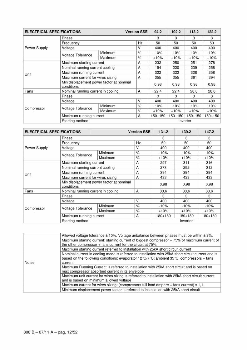
ELECTRICAL SPECIFICATIONS Version SSE 94.2 102.2 113.2 122.2
Phase 3 3 3 3
Frequency Hz 50 50 50 50
Voltage V 400 400 400 400
Minimum % -10% -10% -10% -10%
Power Supply
Voltage Tolerance Maximum % +10% +10% +10% +10%
Maximum starting current A 232 250 251 278
Nominal running current cooling A 194 220 239 258
Maximum running current A 322 322 328 358
Maximum current for wires sizing A 355 355 361 394 Unit
Min displacement power factor at nominal conditions
0,98 0,98 0,98 0,98
Fans Nominal running current in cooling A 22,4 22,4 28,0 28,0
Phase 3 3 3 3
Voltage V 400 400 400 400
Minimum % -10% -10% -10% -10% Voltage Tolerance
Maximum % +10% +10% +10% +10%
Maximum running current A 150+150 150+150 150+150 150+150
Compressor
Starting method Inverter
ELECTRICAL SPECIFICATIONS Version SSE 131.2 139.2 147.2
Phase 3 3 3
Frequency Hz 50 50 50
Voltage V 400 400 400
Minimum % -10% -10% -10%
Power Supply
Voltage Tolerance Maximum % +10% +10% +10%
Maximum starting current A 297 311 316
Nominal running current cooling A 273 292 312
Maximum running current A 394 394 394
Maximum current for wires sizing A 433 433 433 Unit
Min displacement power factor at nominal conditions
0,98 0,98 0,98
Fans Nominal running current in cooling A 33,6 33,6 33,6
Phase 3 3 3
Voltage V 400 400 400
Minimum % -10% -10% -10% Voltage Tolerance
Maximum % +10% +10% +10%
Maximum running current A 180+180 180+180 180+180
Compressor
Starting method Inverter
Allowed voltage tolerance ± 10%. Voltage unbalance between phases must be within ± 3%.
Maximum starting current: starting current of biggest compressor + 75% of maximum current of the other compressor + fans current for the circuit at 75%.
Maximum starting current referred to installation with 25kA short circuit current
Nominal current in cooling mode is referred to installation with 25kA short circuit current and is based on the following conditions: evaporator 12°C/7°C; ambient 35°C; compressors + fans current.
Maximum Running Current is referred to installation with 25kA short circuit and is based on max compressor absorbed current in its envelope
Maximum unit current for wires sizing is referred to installation with 25kA short circuit current and is based on minimum allowed voltage
Maximum current for wires sizing: (compressors full load ampere + fans current) x 1,1.
Notes
Minimum displacement power factor is referred to installation with 25kA short circuit
808 B – 07/11 A – pag. 13/52
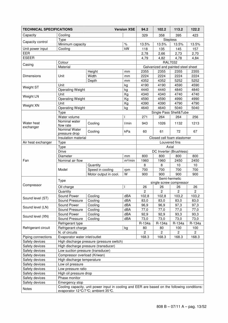
TECHNICAL SPECIFICATIONS Version XSE 94.2 102.2 113.2 122.2
Capacity Cooling 329 358 395 423
Type Stepless Capacity control
Minimum capacity % 13.5% 13.5% 13.5% 13.5%
Unit power input Cooling kW 118 135 145 157
EER 2,78 2,66 2,73 2,70
ESEER 4,79 4,82 4,78 4,84
Colour RAL7032 Casing
Material Galvanized and painted steel sheet
Height mm 2355 2355 2355 2355
Width mm 2224 2224 2224 2224 Dimensions Unit
Depth mm 4352 4352 5252 5252
Unit kg 4190 4190 4590 4590 Weight ST
Operating Weight kg 4440 4440 4840 4840
Unit Kg 4340 4340 4740 4740 Weight LN
Operating Weight Kg 4590 4590 4990 4990
Unit Kg 4390 4390 4790 4790 Weight XN
Operating Weight kg 4640 4640 5040 5040
Type Single Pass Shell&Tube
Water volume l 271 264 264 256
Nominal water flow rate
Cooling l/min 943 1026 1132 1213
Nominal Water pressure drop
Cooling kPa 60 61 72 67
Water heat exchanger
Insulation material Closed cell foam elastomer
Air heat exchanger Type Louvered fins
Type Axial
Drive DC Inverter (Brushless)
Diameter mm 800 800 800 800
Nominal air flow m³/min 1960 1960 2450 2450
Quantity 8 8 10 10
Speed in cooling rpm 700 700 700 700
Fan
Model
Motor output in cool. W 900 900 900 900
Type Semi-hermetic
single screw compressor
Oil charge l 26 26 26 26 Compressor
Quantity 2 2 2 2
Sound Power Cooling dBA 102,8 102,8 103,2 103,2 Sound level (ST)
Sound Pressure Cooling dBA 83,0 83,0 83,0 83,0
Sound Power Cooling dBA 96,9 96,9 97,3 97,3 Sound level (LN)
Sound Pressure Cooling dBA 77,0 77,0 77,0 77,0
Sound Power Cooling dBA 92,9 92,9 93,3 93,3 Sound level (XN)
Sound Pressure Cooling dBA 73,0 73,0 73,0 73,0
Refrigerant type R-134a R-134a R-134a R-134a
Refrigerant charge kg 80 80 100 100 Refrigerant circuit
N. of circuits 2 2 2 2
Piping connections Evaporator water inlet/outlet 168.3 168.3 168.3 168.3
Safety devices High discharge pressure (pressure switch)
Safety devices High discharge pressure (transducer)
Safety devices Low suction pressure (transducer)
Safety devices Compressor overload (Kriwan)
Safety devices High discharge temperature
Safety devices Low oil pressure
Safety devices Low pressure ratio
Safety devices High oil pressure drop
Safety devices Phase monitor
Safety devices Emergency stop
Notes Cooling capacity, unit power input in cooling and EER are based on the following conditions: evaporator 12°C/7°C; ambient 35°C.
808 B – 07/11 A – pag. 14/52
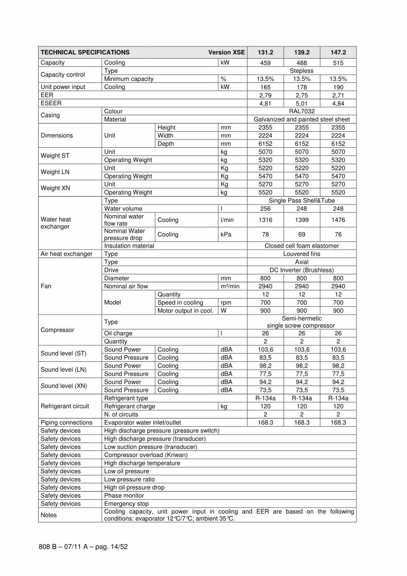
TECHNICAL SPECIFICATIONS Version XSE 131.2 139.2 147.2
Capacity Cooling kW 459 488 515
Type Stepless Capacity control
Minimum capacity % 13.5% 13.5% 13.5%
Unit power input Cooling kW 165 178 190
EER 2,79 2,75 2,71
ESEER 4,81 5,01 4,84
Colour RAL7032 Casing
Material Galvanized and painted steel sheet
Height mm 2355 2355 2355
Width mm 2224 2224 2224 Dimensions Unit
Depth mm 6152 6152 6152
Unit kg 5070 5070 5070
Weight ST Operating Weight kg 5320 5320 5320
Unit Kg 5220 5220 5220 Weight LN
Operating Weight Kg 5470 5470 5470
Unit Kg 5270 5270 5270 Weight XN
Operating Weight kg 5520 5520 5520
Type Single Pass Shell&Tube
Water volume l 256 248 248
Nominal water flow rate
Cooling l/min 1316 1399 1476
Nominal Water pressure drop
Cooling kPa 78 69 76
Water heat exchanger
Insulation material Closed cell foam elastomer
Air heat exchanger Type Louvered fins
Type Axial
Drive DC Inverter (Brushless)
Diameter mm 800 800 800
Nominal air flow m³/min 2940 2940 2940
Quantity 12 12 12
Speed in cooling rpm 700 700 700
Fan
Model
Motor output in cool. W 900 900 900
Type Semi-hermetic
single screw compressor
Oil charge l 26 26 26 Compressor
Quantity 2 2 2
Sound Power Cooling dBA 103,6 103,6 103,6 Sound level (ST)
Sound Pressure Cooling dBA 83,5 83,5 83,5
Sound Power Cooling dBA 98,2 98,2 98,2 Sound level (LN)
Sound Pressure Cooling dBA 77,5 77,5 77,5
Sound Power Cooling dBA 94,2 94,2 94,2 Sound level (XN)
Sound Pressure Cooling dBA 73,5 73,5 73,5
Refrigerant type R-134a R-134a R-134a
Refrigerant charge kg 120 120 120 Refrigerant circuit
N. of circuits 2 2 2
Piping connections Evaporator water inlet/outlet 168.3 168.3 168.3
Safety devices High discharge pressure (pressure switch)
Safety devices High discharge pressure (transducer)
Safety devices Low suction pressure (transducer)
Safety devices Compressor overload (Kriwan)
Safety devices High discharge temperature
Safety devices Low oil pressure
Safety devices Low pressure ratio
Safety devices High oil pressure drop
Safety devices Phase monitor
Safety devices Emergency stop
Notes Cooling capacity, unit power input in cooling and EER are based on the following conditions: evaporator 12°C/7°C; ambient 35°C.
808 B – 07/11 A – pag. 15/52
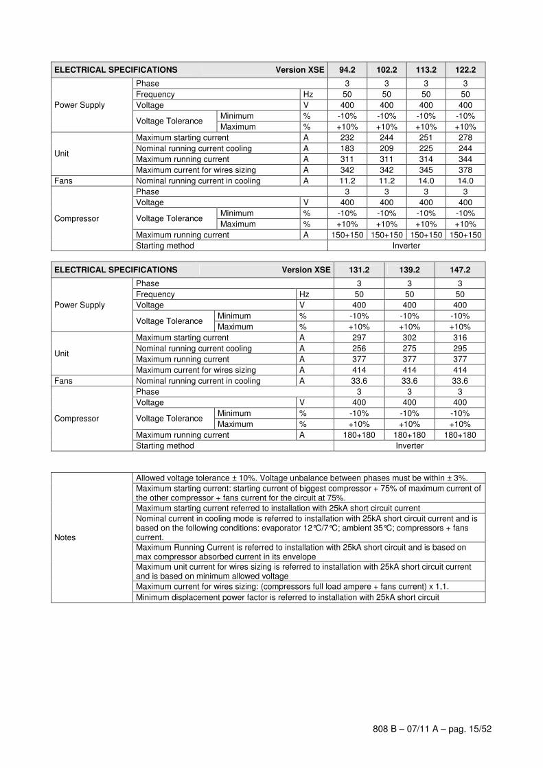
ELECTRICAL SPECIFICATIONS Version XSE 94.2 102.2 113.2 122.2
Phase 3 3 3 3
Frequency Hz 50 50 50 50
Voltage V 400 400 400 400
Minimum % -10% -10% -10% -10%
Power Supply
Voltage Tolerance Maximum % +10% +10% +10% +10%
Maximum starting current A 232 244 251 278
Nominal running current cooling A 183 209 225 244
Maximum running current A 311 311 314 344 Unit
Maximum current for wires sizing A 342 342 345 378
Fans Nominal running current in cooling A 11.2 11.2 14.0 14.0
Phase 3 3 3 3
Voltage V 400 400 400 400
Minimum % -10% -10% -10% -10% Voltage Tolerance
Maximum % +10% +10% +10% +10%
Maximum running current A 150+150 150+150 150+150 150+150
Compressor
Starting method Inverter
ELECTRICAL SPECIFICATIONS Version XSE 131.2 139.2 147.2
Phase 3 3 3
Frequency Hz 50 50 50
Voltage V 400 400 400
Minimum % -10% -10% -10%
Power Supply
Voltage Tolerance Maximum % +10% +10% +10%
Maximum starting current A 297 302 316
Nominal running current cooling A 256 275 295
Maximum running current A 377 377 377 Unit
Maximum current for wires sizing A 414 414 414
Fans Nominal running current in cooling A 33.6 33.6 33.6
Phase 3 3 3
Voltage V 400 400 400
Minimum % -10% -10% -10% Voltage Tolerance
Maximum % +10% +10% +10%
Maximum running current A 180+180 180+180 180+180
Compressor
Starting method Inverter
Allowed voltage tolerance ± 10%. Voltage unbalance between phases must be within ± 3%.
Maximum starting current: starting current of biggest compressor + 75% of maximum current of the other compressor + fans current for the circuit at 75%.
Maximum starting current referred to installation with 25kA short circuit current
Nominal current in cooling mode is referred to installation with 25kA short circuit current and is based on the following conditions: evaporator 12°C/7°C; ambient 35°C; compressors + fans current.
Maximum Running Current is referred to installation with 25kA short circuit and is based on max compressor absorbed current in its envelope
Maximum unit current for wires sizing is referred to installation with 25kA short circuit current and is based on minimum allowed voltage
Maximum current for wires sizing: (compressors full load ampere + fans current) x 1,1.
Notes
Minimum displacement power factor is referred to installation with 25kA short circuit
808 B – 07/11 A – pag. 16/52
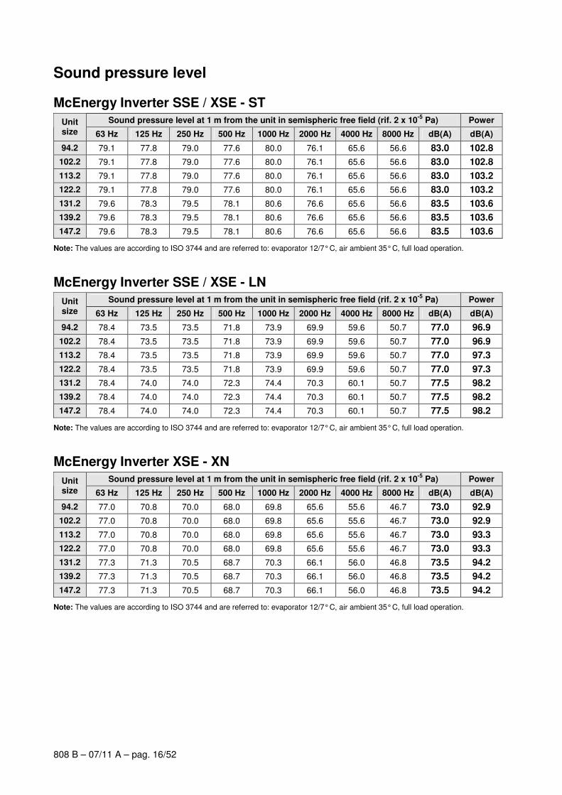
Sound pressure level
McEnergy Inverter SSE / XSE - ST Sound pressure level at 1 m from the unit in semispheric free field (rif. 2 x 10
-5 Pa) Power Unit
size 63 Hz 125 Hz 250 Hz 500 Hz 1000 Hz 2000 Hz 4000 Hz 8000 Hz dB(A) dB(A)
94.2 79.1 77.8 79.0 77.6 80.0 76.1 65.6 56.6 83.0 102.8
102.2 79.1 77.8 79.0 77.6 80.0 76.1 65.6 56.6 83.0 102.8
113.2 79.1 77.8 79.0 77.6 80.0 76.1 65.6 56.6 83.0 103.2
122.2 79.1 77.8 79.0 77.6 80.0 76.1 65.6 56.6 83.0 103.2
131.2 79.6 78.3 79.5 78.1 80.6 76.6 65.6 56.6 83.5 103.6
139.2 79.6 78.3 79.5 78.1 80.6 76.6 65.6 56.6 83.5 103.6
147.2 79.6 78.3 79.5 78.1 80.6 76.6 65.6 56.6 83.5 103.6
Note: The values are according to ISO 3744 and are referred to: evaporator 12/7° C, air ambient 35° C, full load operation.
McEnergy Inverter SSE / XSE - LN Sound pressure level at 1 m from the unit in semispheric free field (rif. 2 x 10
-5 Pa) Power Unit
size 63 Hz 125 Hz 250 Hz 500 Hz 1000 Hz 2000 Hz 4000 Hz 8000 Hz dB(A) dB(A)
94.2 78.4 73.5 73.5 71.8 73.9 69.9 59.6 50.7 77.0 96.9
102.2 78.4 73.5 73.5 71.8 73.9 69.9 59.6 50.7 77.0 96.9
113.2 78.4 73.5 73.5 71.8 73.9 69.9 59.6 50.7 77.0 97.3
122.2 78.4 73.5 73.5 71.8 73.9 69.9 59.6 50.7 77.0 97.3
131.2 78.4 74.0 74.0 72.3 74.4 70.3 60.1 50.7 77.5 98.2
139.2 78.4 74.0 74.0 72.3 74.4 70.3 60.1 50.7 77.5 98.2
147.2 78.4 74.0 74.0 72.3 74.4 70.3 60.1 50.7 77.5 98.2
Note: The values are according to ISO 3744 and are referred to: evaporator 12/7° C, air ambient 35° C, full load operation.
McEnergy Inverter XSE - XN Sound pressure level at 1 m from the unit in semispheric free field (rif. 2 x 10
-5 Pa) Power Unit
size 63 Hz 125 Hz 250 Hz 500 Hz 1000 Hz 2000 Hz 4000 Hz 8000 Hz dB(A) dB(A)
94.2 77.0 70.8 70.0 68.0 69.8 65.6 55.6 46.7 73.0 92.9
102.2 77.0 70.8 70.0 68.0 69.8 65.6 55.6 46.7 73.0 92.9
113.2 77.0 70.8 70.0 68.0 69.8 65.6 55.6 46.7 73.0 93.3
122.2 77.0 70.8 70.0 68.0 69.8 65.6 55.6 46.7 73.0 93.3
131.2 77.3 71.3 70.5 68.7 70.3 66.1 56.0 46.8 73.5 94.2
139.2 77.3 71.3 70.5 68.7 70.3 66.1 56.0 46.8 73.5 94.2
147.2 77.3 71.3 70.5 68.7 70.3 66.1 56.0 46.8 73.5 94.2
Note: The values are according to ISO 3744 and are referred to: evaporator 12/7° C, air ambient 35° C, full load operation.
808 B – 07/11 A – pag. 17/52
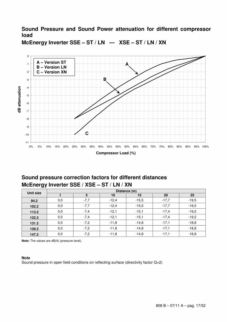
Sound Pressure and Sound Power attenuation for different compressor load
McEnergy Inverter SSE – ST / LN --- XSE – ST / LN / XN
Sound pressure correction factors for different distances
McEnergy Inverter SSE / XSE – ST / LN / XN Distance (m)
Unit size 1 5 10 15 20 25
94.2 0,0 -7,7 -12,4 -15,5 -17,7 -19,5
102.2 0,0 -7,7 -12,4 -15,5 -17,7 -19,5
113.2 0,0 -7,4 -12,1 -15,1 -17,4 -19,2
122.2 0,0 -7,4 -12,1 -15,1 -17,4 -19,2
131.2 0,0 -7,2 -11,8 -14,8 -17,1 -18,8
139.2 0,0 -7,2 -11,8 -14,8 -17,1 -18,8
147.2 0,0 -7,2 -11,8 -14,8 -17,1 -18,8
Note: The values are dB(A) (pressure level).
Note Sound pressure in open field conditions on reflecting surface (directivity factor Q=2)
-11
-10
-9
-8
-7
-6
-5
-4
-3
-2
-1
0
0% 5% 10% 15% 20% 25% 30% 35% 40% 45% 50% 55% 60% 65% 70% 75% 80% 85% 90% 95% 100%
B
A
C
A – Version ST B – Version LN C – Version XN
Compressor Load (%)
dB
att
en
uati
on
808 B – 07/11 A – pag. 18/52
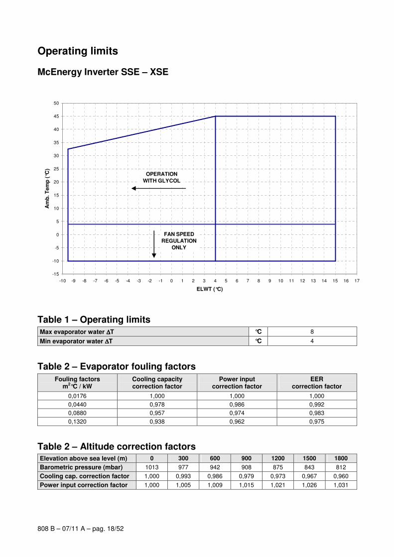
Operating limits
McEnergy Inverter SSE – XSE
-15
-10
-5
0
5
10
15
20
25
30
35
40
45
50
-10 -9 -8 -7 -6 -5 -4 -3 -2 -1 0 1 2 3 4 5 6 7 8 9 10 11 12 13 14 15 16 17
ELWT (°C)
Am
b. T
em
p (
°C)
OPERATION
WITH GLYCOL
FAN SPEED
REGULATION
ONLY
Table 1 – Operating limits
Max evaporator water ∆∆∆∆T °C 8
Min evaporator water ∆∆∆∆T °C 4
Table 2 – Evaporator fouling factors
Fouling factors m
2°C / kW
Cooling capacity correction factor
Power input correction factor
EER correction factor
0,0176 1,000 1,000 1,000
0,0440 0,978 0,986 0,992
0,0880 0,957 0,974 0,983
0,1320 0,938 0,962 0,975
Table 2 – Altitude correction factors Elevation above sea level (m) 0 300 600 900 1200 1500 1800
Barometric pressure (mbar) 1013 977 942 908 875 843 812
Cooling cap. correction factor 1,000 0,993 0,986 0,979 0,973 0,967 0,960
Power input correction factor 1,000 1,005 1,009 1,015 1,021 1,026 1,031
808 B – 07/11 A – pag. 19/52
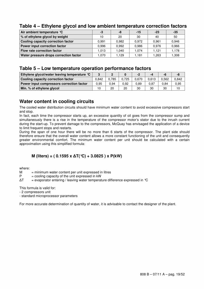
Table 4 – Ethylene glycol and low ambient temperature correction factors Air ambient temperature °C -3 -8 -15 -23 -35
% of ethylene glycol by weight 10 20 30 40 50
Cooling capacity correction factor 0,991 0,982 0,972 0,961 0,946
Power input correction factor 0,996 0,992 0,986 0,976 0,966
Flow rate correction factor 1,013 1,040 1,074 1,121 1,178
Water pressure drops correction factor 1,070 1,129 1,181 1,263 1,308
Table 5 – Low temperature operation performance factors Ethylene glycol/water leaving temperature °C 3 2 0 -2 -4 -6 -8
Cooling capacity correction factor 0,842 0,785 0,725 0,670 0,613 0,562 0,842
Power input compressors correction factor 0,95 0,94 0,92 0,89 0,87 0,84 0,95
Min. % of ethylene glycol 10 20 20 30 30 30 10
Water content in cooling circuits The cooled water distribution circuits should have minimum water content to avoid excessive compressors start
and stop.
In fact, each time the compressor starts up, an excessive quantity of oil goes from the compressor sump and
simultaneously there is a rise in the temperature of the compressor motor’s stator due to the inrush current
during the start-up. To prevent damage to the compressors, McQuay has envisaged the application of a device
to limit frequent stops and restarts. During the span of one hour there will be no more than 6 starts of the compressor. The plant side should therefore ensure that the overall water content allows a more constant functioning of the unit and consequently greater environmental comfort. The minimum water content per unit should be calculated with a certain approximation using this simplified formula:
M (liters) = ( 0.1595 x ∆T(°C) + 3.0825 ) x P(kW) where: M = minimum water content per unit expressed in litres P = cooling capacity of the unit expressed in kW
∆T = evaporator entering / leaving water temperature difference expressed in °C This formula is valid for: - 2 compressors unit - standard microprocessor parameters
For more accurate determination of quantity of water, it is advisable to contact the designer of the plant.
808 B – 07/11 A – pag. 20/52
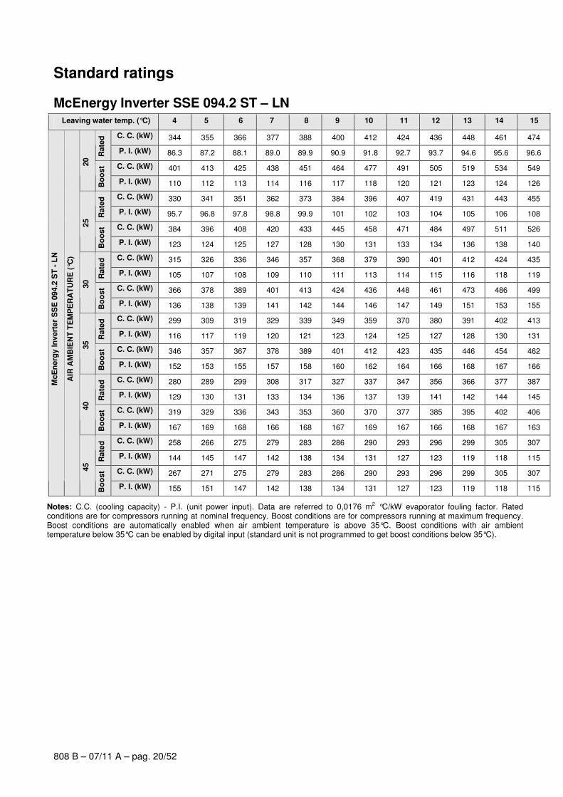
Standard ratings
McEnergy Inverter SSE 094.2 ST – LN Leaving water temp. (°C) 4 5 6 7 8 9 10 11 12 13 14 15
C. C. (kW) 344 355 366 377 388 400 412 424 436 448 461 474
Rate
d
P. I. (kW) 86.3 87.2 88.1 89.0 89.9 90.9 91.8 92.7 93.7 94.6 95.6 96.6
C. C. (kW) 401 413 425 438 451 464 477 491 505 519 534 549
20
Bo
ost
P. I. (kW) 110 112 113 114 116 117 118 120 121 123 124 126
C. C. (kW) 330 341 351 362 373 384 396 407 419 431 443 455
Rate
d
P. I. (kW) 95.7 96.8 97.8 98.8 99.9 101 102 103 104 105 106 108
C. C. (kW) 384 396 408 420 433 445 458 471 484 497 511 526
25
Bo
ost
P. I. (kW) 123 124 125 127 128 130 131 133 134 136 138 140
C. C. (kW) 315 326 336 346 357 368 379 390 401 412 424 435
Rate
d
P. I. (kW) 105 107 108 109 110 111 113 114 115 116 118 119
C. C. (kW) 366 378 389 401 413 424 436 448 461 473 486 499
30
Bo
ost
P. I. (kW) 136 138 139 141 142 144 146 147 149 151 153 155
C. C. (kW) 299 309 319 329 339 349 359 370 380 391 402 413
Rate
d
P. I. (kW) 116 117 119 120 121 123 124 125 127 128 130 131
C. C. (kW) 346 357 367 378 389 401 412 423 435 446 454 462
35
Bo
ost
P. I. (kW) 152 153 155 157 158 160 162 164 166 168 167 166
C. C. (kW) 280 289 299 308 317 327 337 347 356 366 377 387
Rate
d
P. I. (kW) 129 130 131 133 134 136 137 139 141 142 144 145
C. C. (kW) 319 329 336 343 353 360 370 377 385 395 402 406
40
Bo
ost
P. I. (kW) 167 169 168 166 168 167 169 167 166 168 167 163
C. C. (kW) 258 266 275 279 283 286 290 293 296 299 305 307
Rate
d
P. I. (kW) 144 145 147 142 138 134 131 127 123 119 118 115
C. C. (kW) 267 271 275 279 283 286 290 293 296 299 305 307
McE
nerg
y In
vert
er
SS
E 0
94.2
ST
- L
N
AIR
AM
BIE
NT
TE
MP
ER
AT
UR
E (
°C)
45
Bo
ost
P. I. (kW) 155 151 147 142 138 134 131 127 123 119 118 115
Notes: C.C. (cooling capacity) - P.I. (unit power input). Data are referred to 0,0176 m2 °C/kW evaporator fouling factor. Rated conditions are for compressors running at nominal frequency. Boost conditions are for compressors running at maximum frequency. Boost conditions are automatically enabled when air ambient temperature is above 35°C. Boost conditions with air ambient temperature below 35°C can be enabled by digital input (standard unit is not programmed to get boost conditions below 35°C).

808 B – 07/11 A – pag. 21/52
McEnergy Inverter SSE 102.2 ST – LN Leaving water temp. (°C) 4 5 6 7 8 9 10 11 12 13 14 15
C. C. (kW) 378 390 402 414 426 439 452 465 478 491 505 519 R
ate
d
P. I. (kW) 97.9 99.0 100 101 103 104 105 106 107 109 110 111
C. C. (kW) 439 452 466 480 493 507 522 537 551 567 582 597
20
Bo
ost
P. I. (kW) 126 128 130 131 133 135 136 138 140 142 144 146
C. C. (kW) 362 374 385 397 409 421 434 446 459 472 485 498
Rate
d
P. I. (kW) 108 110 111 112 114 115 116 118 119 121 122 123
C. C. (kW) 420 433 446 459 472 486 497 508 519 533 545 557
25
Bo
ost
P. I. (kW) 140 142 144 146 148 150 150 150 151 153 153 154
C. C. (kW) 345 356 368 379 390 402 414 425 437 450 462 474
Rate
d
P. I. (kW) 119 121 122 124 125 127 128 130 131 133 135 136
C. C. (kW) 396 406 416 428 438 449 459 472 483 493 504 517
30
Bo
ost
P. I. (kW) 153 153 153 155 156 156 157 159 159 160 160 162
C. C. (kW) 326 337 347 358 369 380 391 402 413 425 436 446
Rate
d
P. I. (kW) 132 133 135 136 138 140 142 143 145 147 149 149
C. C. (kW) 362 371 382 392 402 413 423 433 445 453 463 471
35
Bo
ost
P. I. (kW) 160 160 162 163 163 165 166 166 168 167 168 167
C. C. (kW) 304 314 324 332 343 351 362 370 379 388 395 403
Rate
d
P. I. (kW) 146 148 150 150 152 152 154 154 154 154 153 151
C. C. (kW) 325 334 343 350 361 368 377 386 393 401 407 411
40
Bo
ost
P. I. (kW) 167 168 168 167 169 167 168 168 167 166 163 158
C. C. (kW) 266 273 278 283 286 290 293 297 301 303 307 308
Rate
d
P. I. (kW) 146 144 141 138 134 130 126 123 121 117 114 110
C. C. (kW) 270 274 278 283 286 290 293 297 301 303 307 308
McE
nerg
y In
vert
er
SS
E 1
03.2
ST
- L
N
AIR
AM
BIE
NT
TE
MP
ER
AT
UR
E (
°C)
45
Bo
ost
P. I. (kW) 150 146 141 138 134 130 126 123 121 117 114 110
Notes: C.C. (cooling capacity) - P.I. (unit power input). Data are referred to 0,0176 m2 °C/kW evaporator fouling factor. Rated conditions are for compressors running at nominal frequency. Boost conditions are for compressors running at maximum frequency. Boost conditions are automatically enabled when air ambient temperature is above 35°C. Boost conditions with air ambient temperature below 35°C can be enabled by digital input (standard unit is not programmed to get boost conditions below 35°C).
808 B – 07/11 A – pag. 22/52
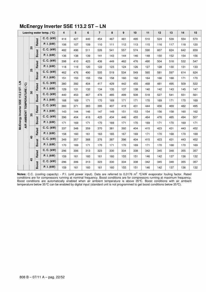
McEnergy Inverter SSE 113.2 ST – LN Leaving water temp. (°C) 4 5 6 7 8 9 10 11 12 13 14 15
C. C. (kW) 414 427 440 454 467 481 495 510 524 539 554 570 R
ate
d
P. I. (kW) 106 107 109 110 111 112 113 115 116 117 118 120
C. C. (kW) 482 496 511 526 541 557 574 590 607 624 642 659
20
Bo
ost
P. I. (kW) 136 138 139 141 143 144 146 148 150 152 154 156
C. C. (kW) 398 410 423 436 449 462 476 490 504 518 532 547
Rate
d
P. I. (kW) 118 119 120 122 123 124 126 127 128 130 131 133
C. C. (kW) 462 476 490 505 519 534 549 565 581 597 614 624
25
Bo
ost
P. I. (kW) 151 153 155 156 158 160 162 164 166 168 171 170
C. C. (kW) 380 392 404 417 429 442 455 468 481 495 509 522
Rate
d
P. I. (kW) 129 131 132 134 135 137 138 140 142 143 145 147
C. C. (kW) 440 453 467 476 485 499 508 518 527 541 551 561
30
Bo
ost
P. I. (kW) 168 169 171 170 169 171 171 170 169 171 170 169
C. C. (kW) 360 371 383 395 407 419 431 444 456 469 482 495
Rate
d
P. I. (kW) 143 144 146 147 149 151 153 154 156 158 160 162
C. C. (kW) 396 404 416 425 434 446 455 464 476 485 494 507
35
Bo
ost
P. I. (kW) 171 169 171 170 169 171 170 169 171 170 169 171
C. C. (kW) 337 348 359 370 381 392 404 415 423 431 443 452
Rate
d
P. I. (kW) 158 160 161 163 165 167 169 171 170 168 170 169
C. C. (kW) 349 357 368 376 387 396 404 415 423 431 443 452
40
Bo
ost
P. I. (kW) 170 169 171 170 171 170 169 171 170 168 170 169
C. C. (kW) 296 306 313 323 330 334 338 342 345 348 355 357
Rate
d
P. I. (kW) 159 161 160 161 160 155 151 146 142 137 136 132
C. C. (kW) 296 306 313 323 330 334 338 342 345 348 355 357
McE
nerg
y In
vert
er
SS
E 1
12.2
ST
- L
N
AIR
AM
BIE
NT
TE
MP
ER
AT
UR
E (
°C)
45
Bo
ost
P. I. (kW) 159 161 160 161 160 155 151 146 142 137 136 132
Notes: C.C. (cooling capacity) - P.I. (unit power input). Data are referred to 0,0176 m2 °C/kW evaporator fouling factor. Rated conditions are for compressors running at nominal frequency. Boost conditions are for compressors running at maximum frequency. Boost conditions are automatically enabled when air ambient temperature is above 35°C. Boost conditions with air ambient temperature below 35°C can be enabled by digital input (standard unit is not programmed to get boost conditions below 35°C).

808 B – 07/11 A – pag. 23/52
McEnergy Inverter SSE 122.2 ST – LN Leaving water temp. (°C) 4 5 6 7 8 9 10 11 12 13 14 15
C. C. (kW) 445 459 473 488 503 517 533 548 563 579 595 612 R
ate
d
P. I. (kW) 115 116 117 119 120 121 123 124 125 127 128 130
C. C. (kW) 518 533 549 565 582 599 616 633 651 669 688 706
20
Bo
ost
P. I. (kW) 147 149 151 153 155 157 159 161 163 165 167 170
C. C. (kW) 427 441 455 468 483 497 511 526 541 556 572 587
Rate
d
P. I. (kW) 127 128 130 131 133 134 136 137 139 141 142 144
C. C. (kW) 496 511 526 542 558 573 589 606 623 640 654 668
25
Bo
ost
P. I. (kW) 164 166 168 170 172 174 176 178 181 183 184 185
C. C. (kW) 408 421 434 447 461 475 488 502 517 531 546 560
Rate
d
P. I. (kW) 140 141 143 145 146 148 150 152 153 155 157 159
C. C. (kW) 472 486 499 511 523 533 543 558 568 578 590 604
30
Bo
ost
P. I. (kW) 182 184 185 185 186 185 184 186 185 184 185 186
C. C. (kW) 386 398 411 423 436 449 462 475 489 502 516 530
Rate
d
P. I. (kW) 154 156 158 159 161 163 165 167 169 171 173 175
C. C. (kW) 424 435 444 455 467 476 487 499 508 520 531 541
35
Bo
ost
P. I. (kW) 185 185 184 185 185 184 184 185 184 184 185 184
C. C. (kW) 360 372 384 395 407 420 432 442 455 464 474 485
Rate
d
P. I. (kW) 171 173 175 177 179 181 183 183 186 184 185 185
C. C. (kW) 373 384 394 404 413 425 434 442 455 464 474 485
40
Bo
ost
P. I. (kW) 184 185 185 185 184 186 185 183 186 184 185 185
C. C. (kW) 318 324 331 337 345 349 353 356 361 366 369 371
Rate
d
P. I. (kW) 174 170 169 165 164 159 154 149 146 143 138 134
C. C. (kW) 318 324 331 337 345 349 353 356 361 366 369 371
McE
nerg
y In
vert
er
SS
E 1
21.2
ST
- L
N
AIR
AM
BIE
NT
TE
MP
ER
AT
UR
E (
°C)
45
Bo
ost
P. I. (kW) 174 170 169 165 164 159 154 149 146 143 138 134
Notes: C.C. (cooling capacity) - P.I. (unit power input). Data are referred to 0,0176 m2 °C/kW evaporator fouling factor. Rated conditions are for compressors running at nominal frequency. Boost conditions are for compressors running at maximum frequency. Boost conditions are automatically enabled when air ambient temperature is above 35°C. Boost conditions with air ambient temperature below 35°C can be enabled by digital input (standard unit is not programmed to get boost conditions below 35°C).

808 B – 07/11 A – pag. 24/52
McEnergy Inverter SSE 131.2 ST – LN Leaving water temp. (°C) 4 5 6 7 8 9 10 11 12 13 14 15
C. C. (kW) 480 496 511 527 542 559 575 592 609 626 644 661 R
ate
d
P. I. (kW) 121 122 124 125 126 127 129 130 131 133 134 135
C. C. (kW) 560 577 594 611 629 647 666 686 705 726 746 767
20
Bo
ost
P. I. (kW) 154 156 158 160 162 164 165 168 170 172 174 176
C. C. (kW) 461 476 491 506 521 537 553 569 585 602 619 636
Rate
d
P. I. (kW) 134 136 137 139 140 141 143 145 146 148 149 151
C. C. (kW) 537 553 570 587 604 622 639 657 676 695 714 734
25
Bo
ost
P. I. (kW) 172 174 175 177 180 182 184 186 188 191 193 196
C. C. (kW) 441 455 469 484 499 514 529 544 560 576 592 608
Rate
d
P. I. (kW) 148 149 151 153 154 156 158 159 161 163 165 167
C. C. (kW) 512 528 544 560 576 592 609 620 631 642 660 671
30
Bo
ost
P. I. (kW) 190 192 195 197 199 201 204 203 202 200 203 202
C. C. (kW) 418 431 445 459 473 487 502 516 531 546 561 576
Rate
d
P. I. (kW) 162 164 166 168 170 172 174 176 178 180 182 184
C. C. (kW) 469 484 494 504 519 529 544 555 565 581 591 602
35
Bo
ost
P. I. (kW) 201 203 202 200 203 201 204 202 201 203 202 201
C. C. (kW) 392 404 417 430 443 457 470 484 498 512 526 540
Rate
d
P. I. (kW) 180 182 184 186 188 190 192 194 196 199 201 203
C. C. (kW) 414 427 437 450 459 469 483 492 506 516 526 540
40
Bo
ost
P. I. (kW) 201 203 201 204 202 201 203 201 204 202 201 203
C. C. (kW) 354 362 374 383 395 400 405 409 414 418 421 429
Rate
d
P. I. (kW) 193 191 193 191 193 188 182 177 172 167 162 160
C. C. (kW) 354 362 374 383 395 400 405 409 414 418 421 429
McE
nerg
y In
vert
er
SS
E 1
30.2
ST
- L
N
AIR
AM
BIE
NT
TE
MP
ER
AT
UR
E (
°C)
45
Bo
ost
P. I. (kW) 193 191 193 191 193 188 182 177 172 167 162 160
Notes: C.C. (cooling capacity) - P.I. (unit power input). Data are referred to 0,0176 m2 °C/kW evaporator fouling factor. Rated conditions are for compressors running at nominal frequency. Boost conditions are for compressors running at maximum frequency. Boost conditions are automatically enabled when air ambient temperature is above 35°C. Boost conditions with air ambient temperature below 35°C can be enabled by digital input (standard unit is not programmed to get boost conditions below 35°C).

808 B – 07/11 A – pag. 25/52
McEnergy Inverter SSE 139.2 ST – LN Leaving water temp. (°C) 4 5 6 7 8 9 10 11 12 13 14 15
C. C. (kW) 512 528 544 561 578 595 612 630 648 667 686 705 R
ate
d
P. I. (kW) 130 131 133 134 136 137 139 140 142 143 145 146
C. C. (kW) 596 614 632 651 670 689 709 730 751 772 793 811
20
Bo
ost
P. I. (kW) 166 168 170 172 174 177 179 181 183 186 188 189
C. C. (kW) 491 507 523 539 555 572 589 606 623 640 658 677
Rate
d
P. I. (kW) 144 146 147 149 150 152 154 156 157 159 161 163
C. C. (kW) 571 589 606 621 636 654 669 685 704 720 737 754
25
Bo
ost
P. I. (kW) 185 187 189 190 190 193 193 194 196 197 198 198
C. C. (kW) 469 485 500 515 531 547 563 579 595 612 629 646
Rate
d
P. I. (kW) 159 160 162 164 166 168 170 171 173 175 177 179
C. C. (kW) 531 547 561 575 591 606 617 634 646 657 672 687
30
Bo
ost
P. I. (kW) 196 198 199 199 202 202 201 203 202 201 202 203
C. C. (kW) 445 459 474 488 503 518 533 549 562 577 590 604
Rate
d
P. I. (kW) 175 177 179 181 183 185 187 189 189 192 192 192
C. C. (kW) 480 495 505 516 531 542 555 568 579 592 606 616
35
Bo
ost
P. I. (kW) 201 203 202 200 203 201 202 202 201 202 202 201
C. C. (kW) 414 426 439 451 462 476 488 502 514 526 541 553
Rate
d
P. I. (kW) 191 192 194 194 194 196 197 199 199 200 202 202
C. C. (kW) 425 437 449 459 470 482 494 506 516 528 541 553
40
Bo
ost
P. I. (kW) 202 202 203 201 201 202 202 203 201 201 202 202
C. C. (kW) 364 372 384 393 404 411 421 426 433 437 440 444
Rate
d
P. I. (kW) 192 191 193 191 191 187 188 182 179 173 168 162
C. C. (kW) 364 372 384 393 404 411 421 426 433 437 440 444
McE
nerg
y In
vert
er
SS
E 1
39.2
ST
- L
N
AIR
AM
BIE
NT
TE
MP
ER
AT
UR
E (
°C)
45
Bo
ost
P. I. (kW) 192 191 193 191 191 187 188 182 179 173 168 162
Notes: C.C. (cooling capacity) - P.I. (unit power input). Data are referred to 0,0176 m2 °C/kW evaporator fouling factor. Rated conditions are for compressors running at nominal frequency. Boost conditions are for compressors running at maximum frequency. Boost conditions are automatically enabled when air ambient temperature is above 35°C. Boost conditions with air ambient temperature below 35°C can be enabled by digital input (standard unit is not programmed to get boost conditions below 35°C).

808 B – 07/11 A – pag. 26/52
McEnergy Inverter SSE 147.2 ST – LN Leaving water temp. (°C) 4 5 6 7 8 9 10 11 12 13 14 15
C. C. (kW) 541 558 575 592 610 628 646 665 684 703 724 745 R
ate
d
P. I. (kW) 139 140 142 143 145 147 148 150 151 153 155 157
C. C. (kW) 628 647 667 686 706 728 749 771 793 815 837 852
20
Bo
ost
P. I. (kW) 178 180 182 185 187 189 192 194 197 199 202 201
C. C. (kW) 519 536 552 569 586 604 621 639 657 676 694 714
Rate
d
P. I. (kW) 154 155 157 159 161 163 164 166 168 170 172 174
C. C. (kW) 603 621 639 652 664 683 696 709 729 743 756 770
25
Bo
ost
P. I. (kW) 198 200 203 202 201 203 202 201 204 203 202 201
C. C. (kW) 496 512 528 544 560 577 594 611 628 645 663 681
Rate
d
P. I. (kW) 169 171 173 175 177 179 181 183 185 188 190 192
C. C. (kW) 547 563 575 587 604 616 627 645 657 669 681 699
30
Bo
ost
P. I. (kW) 201 204 203 201 204 203 201 204 203 201 200 203
C. C. (kW) 470 485 500 515 531 547 562 578 590 606 617 628
Rate
d
P. I. (kW) 187 189 191 193 195 198 200 202 201 203 202 200
C. C. (kW) 488 503 514 525 541 551 567 578 590 606 617 628
35
Bo
ost
P. I. (kW) 201 203 202 200 203 201 204 202 201 203 202 200
C. C. (kW) 435 445 459 469 479 494 504 518 528 539 554 564
Rate
d
P. I. (kW) 203 201 204 202 200 203 201 203 202 200 202 201
C. C. (kW) 435 445 459 469 479 494 504 518 528 539 554 564
40
Bo
ost
P. I. (kW) 203 201 204 202 200 203 201 203 202 200 202 201
C. C. (kW) 372 381 393 402 415 424 437 441 450 454 458 461
Rate
d
P. I. (kW) 192 190 192 190 193 191 193 187 185 179 174 168
C. C. (kW) 372 381 393 402 415 424 437 441 450 454 458 461
McE
nerg
y In
vert
er
SS
E 1
47.2
ST
- L
N
AIR
AM
BIE
NT
TE
MP
ER
AT
UR
E (
°C)
45
Bo
ost
P. I. (kW) 192 190 192 190 193 191 193 187 185 179 174 168
Notes: C.C. (cooling capacity) - P.I. (unit power input). Data are referred to 0,0176 m2 °C/kW evaporator fouling factor. Rated conditions are for compressors running at nominal frequency. Boost conditions are for compressors running at maximum frequency. Boost conditions are automatically enabled when air ambient temperature is above 35°C. Boost conditions with air ambient temperature below 35°C can be enabled by digital input (standard unit is not programmed to get boost conditions below 35°C).

808 B – 07/11 A – pag. 27/52
McEnergy Inverter XSE 094.2 ST – LN – XN Leaving water temp. (°C) 4 5 6 7 8 9 10 11 12 13 14 15
C. C. (kW) 344 355 366 377 388 400 412 424 436 448 461 474 R
ate
d
P. I. (kW) 84.4 85.3 86.2 87.1 88.0 89.0 89.9 90.8 91.8 92.7 93.7 94.7
C. C. (kW) 401 413 425 438 451 464 477 491 505 519 534 549
20
Bo
ost
P. I. (kW) 108 110 111 112 114 115 116 118 119 121 122 124
C. C. (kW) 330 341 351 362 373 384 396 407 419 431 443 455
Rate
d
P. I. (kW) 93.8 94.9 95.9 96.9 98.0 99.1 100 101 102 104 105 106
C. C. (kW) 384 396 408 420 433 445 458 471 484 497 511 526
25
Bo
ost
P. I. (kW) 121 122 124 125 126 128 130 131 133 134 136 138
C. C. (kW) 315 326 336 346 357 368 379 390 401 412 424 435
Rate
d
P. I. (kW) 104 105 106 107 108 109 111 112 113 115 116 117
C. C. (kW) 366 378 389 401 413 424 436 448 461 473 486 499
30
Bo
ost
P. I. (kW) 134 136 137 139 140 142 144 146 147 149 151 153
C. C. (kW) 299 309 319 329 339 349 359 370 380 391 402 413
Rate
d
P. I. (kW) 114 116 117 118 119 121 122 124 125 127 128 130
C. C. (kW) 346 357 367 378 389 397 404 416 423 431 442 450
35
Bo
ost
P. I. (kW) 150 151 153 155 157 156 155 157 156 155 156 156
C. C. (kW) 280 289 299 308 317 327 337 347 356 366 377 387
Rate
d
P. I. (kW) 127 128 130 131 132 134 136 137 139 140 142 144
C. C. (kW) 319 329 336 343 353 360 370 377 385 395 402 406
40
Bo
ost
P. I. (kW) 165 167 166 164 166 165 167 166 164 166 165 161
C. C. (kW) 258 266 275 279 283 286 290 293 296 299 305 307
Rate
d
P. I. (kW) 142 143 145 141 137 133 129 125 121 118 116 113
C. C. (kW) 267 271 275 279 283 286 290 293 296 299 305 307
McE
nerg
y In
vert
er
XS
E 0
94.2
ST
– L
N -
XN
AIR
AM
BIE
NT
TE
MP
ER
AT
UR
E (
°C)
45
Bo
ost
P. I. (kW) 154 149 145 141 137 133 129 125 121 118 116 113
Notes: C.C. (cooling capacity) - P.I. (unit power input). Data are referred to 0,0176 m2 °C/kW evaporator fouling factor. Rated conditions are for compressors running at nominal frequency. Boost conditions are for compressors running at maximum frequency. Boost conditions are automatically enabled when air ambient temperature is above 35°C. Boost conditions with air ambient temperature below 35°C can be enabled by digital input (standard unit is not programmed to get boost conditions below 35°C).

808 B – 07/11 A – pag. 28/52
McEnergy Inverter XSE 102.2 ST – LN – XN Leaving water temp. (°C) 4 5 6 7 8 9 10 11 12 13 14 15
C. C. (kW) 378 390 402 414 426 439 452 465 478 491 505 519 R
ate
d
P. I. (kW) 96.0 97.1 98.3 99.4 101 102 103 104 106 107 108 109
C. C. (kW) 439 452 466 480 493 507 522 537 551 567 582 597
20
Bo
ost
P. I. (kW) 124 126 128 129 131 133 135 136 138 140 142 144
C. C. (kW) 362 374 385 397 409 421 434 446 459 472 485 498
Rate
d
P. I. (kW) 106 108 109 110 112 113 114 116 117 119 120 122
C. C. (kW) 420 433 446 459 472 486 497 508 519 533 545 557
25
Bo
ost
P. I. (kW) 138 140 142 144 146 148 148 148 149 151 151 152
C. C. (kW) 345 356 368 379 390 402 414 425 437 450 462 474
Rate
d
P. I. (kW) 117 119 120 122 123 125 126 128 130 131 133 135
C. C. (kW) 396 406 416 428 438 449 459 472 483 493 504 517
30
Bo
ost
P. I. (kW) 151 151 152 153 154 154 155 157 157 158 158 160
C. C. (kW) 326 337 347 358 369 380 391 402 413 425 436 446
Rate
d
P. I. (kW) 130 131 133 135 136 138 140 141 143 145 147 147
C. C. (kW) 362 371 382 392 402 413 423 433 445 453 463 471
35
Bo
ost
P. I. (kW) 158 159 161 161 161 163 164 164 166 165 166 165
C. C. (kW) 304 314 324 332 343 351 362 370 379 388 395 403
Rate
d
P. I. (kW) 144 146 148 148 150 150 152 152 152 152 151 149
C. C. (kW) 325 334 343 350 361 368 377 386 393 401 407 411
40
Bo
ost
P. I. (kW) 165 166 166 165 167 165 166 166 165 164 161 157
C. C. (kW) 266 273 278 283 286 290 293 297 301 303 307 308
Rate
d
P. I. (kW) 144 142 139 137 132 128 124 122 119 115 112 108
C. C. (kW) 270 274 278 283 286 290 293 297 301 303 307 308
McE
nerg
y In
vert
er
XS
E 1
03.2
ST
- L
N
AIR
AM
BIE
NT
TE
MP
ER
AT
UR
E (
°C)
45
Bo
ost
P. I. (kW) 148 144 139 137 132 128 124 122 119 115 112 108
Notes: C.C. (cooling capacity) - P.I. (unit power input). Data are referred to 0,0176 m2 °C/kW evaporator fouling factor. Rated conditions are for compressors running at nominal frequency. Boost conditions are for compressors running at maximum frequency. Boost conditions are automatically enabled when air ambient temperature is above 35°C. Boost conditions with air ambient temperature below 35°C can be enabled by digital input (standard unit is not programmed to get boost conditions below 35°C).
808 B – 07/11 A – pag. 29/52
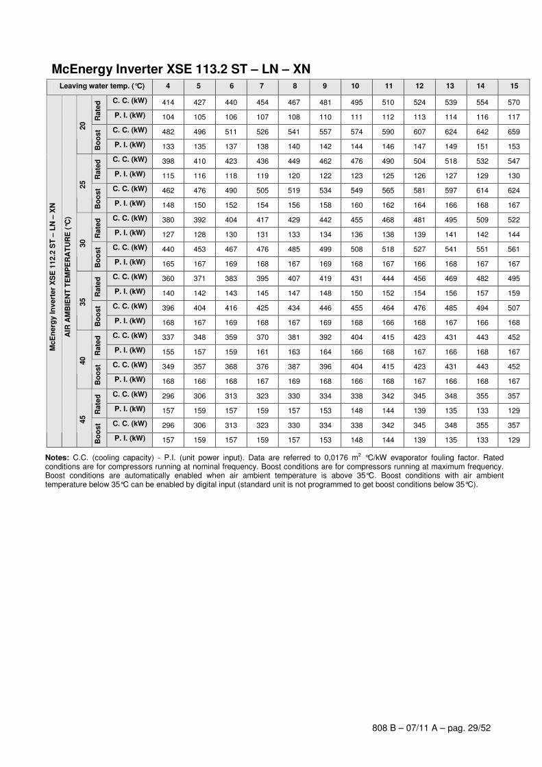
McEnergy Inverter XSE 113.2 ST – LN – XN Leaving water temp. (°C) 4 5 6 7 8 9 10 11 12 13 14 15
C. C. (kW) 414 427 440 454 467 481 495 510 524 539 554 570 R
ate
d
P. I. (kW) 104 105 106 107 108 110 111 112 113 114 116 117
C. C. (kW) 482 496 511 526 541 557 574 590 607 624 642 659
20
Bo
ost
P. I. (kW) 133 135 137 138 140 142 144 146 147 149 151 153
C. C. (kW) 398 410 423 436 449 462 476 490 504 518 532 547
Rate
d
P. I. (kW) 115 116 118 119 120 122 123 125 126 127 129 130
C. C. (kW) 462 476 490 505 519 534 549 565 581 597 614 624
25
Bo
ost
P. I. (kW) 148 150 152 154 156 158 160 162 164 166 168 167
C. C. (kW) 380 392 404 417 429 442 455 468 481 495 509 522
Rate
d
P. I. (kW) 127 128 130 131 133 134 136 138 139 141 142 144
C. C. (kW) 440 453 467 476 485 499 508 518 527 541 551 561
30
Bo
ost
P. I. (kW) 165 167 169 168 167 169 168 167 166 168 167 167
C. C. (kW) 360 371 383 395 407 419 431 444 456 469 482 495
Rate
d
P. I. (kW) 140 142 143 145 147 148 150 152 154 156 157 159
C. C. (kW) 396 404 416 425 434 446 455 464 476 485 494 507
35
Bo
ost
P. I. (kW) 168 167 169 168 167 169 168 166 168 167 166 168
C. C. (kW) 337 348 359 370 381 392 404 415 423 431 443 452
Rate
d
P. I. (kW) 155 157 159 161 163 164 166 168 167 166 168 167
C. C. (kW) 349 357 368 376 387 396 404 415 423 431 443 452
40
Bo
ost
P. I. (kW) 168 166 168 167 169 168 166 168 167 166 168 167
C. C. (kW) 296 306 313 323 330 334 338 342 345 348 355 357
Rate
d
P. I. (kW) 157 159 157 159 157 153 148 144 139 135 133 129
C. C. (kW) 296 306 313 323 330 334 338 342 345 348 355 357
McE
nerg
y In
vert
er
XS
E 1
12.2
ST
– L
N –
XN
AIR
AM
BIE
NT
TE
MP
ER
AT
UR
E (
°C)
45
Bo
ost
P. I. (kW) 157 159 157 159 157 153 148 144 139 135 133 129
Notes: C.C. (cooling capacity) - P.I. (unit power input). Data are referred to 0,0176 m2 °C/kW evaporator fouling factor. Rated conditions are for compressors running at nominal frequency. Boost conditions are for compressors running at maximum frequency. Boost conditions are automatically enabled when air ambient temperature is above 35°C. Boost conditions with air ambient temperature below 35°C can be enabled by digital input (standard unit is not programmed to get boost conditions below 35°C).
808 B – 07/11 A – pag. 30/52
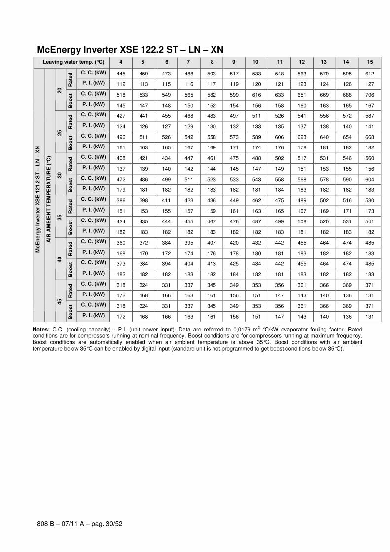
McEnergy Inverter XSE 122.2 ST – LN – XN Leaving water temp. (°C) 4 5 6 7 8 9 10 11 12 13 14 15
C. C. (kW) 445 459 473 488 503 517 533 548 563 579 595 612 R
ate
d
P. I. (kW) 112 113 115 116 117 119 120 121 123 124 126 127
C. C. (kW) 518 533 549 565 582 599 616 633 651 669 688 706
20
Bo
ost
P. I. (kW) 145 147 148 150 152 154 156 158 160 163 165 167
C. C. (kW) 427 441 455 468 483 497 511 526 541 556 572 587
Rate
d
P. I. (kW) 124 126 127 129 130 132 133 135 137 138 140 141
C. C. (kW) 496 511 526 542 558 573 589 606 623 640 654 668
25
Bo
ost
P. I. (kW) 161 163 165 167 169 171 174 176 178 181 182 182
C. C. (kW) 408 421 434 447 461 475 488 502 517 531 546 560
Rate
d
P. I. (kW) 137 139 140 142 144 145 147 149 151 153 155 156
C. C. (kW) 472 486 499 511 523 533 543 558 568 578 590 604
30
Bo
ost
P. I. (kW) 179 181 182 182 183 182 181 184 183 182 182 183
C. C. (kW) 386 398 411 423 436 449 462 475 489 502 516 530
Rate
d
P. I. (kW) 151 153 155 157 159 161 163 165 167 169 171 173
C. C. (kW) 424 435 444 455 467 476 487 499 508 520 531 541
35
Bo
ost
P. I. (kW) 182 183 182 182 183 182 182 183 181 182 183 182
C. C. (kW) 360 372 384 395 407 420 432 442 455 464 474 485
Rate
d
P. I. (kW) 168 170 172 174 176 178 180 181 183 182 182 183
C. C. (kW) 373 384 394 404 413 425 434 442 455 464 474 485
40
Bo
ost
P. I. (kW) 182 182 182 183 182 184 182 181 183 182 182 183
C. C. (kW) 318 324 331 337 345 349 353 356 361 366 369 371
Rate
d
P. I. (kW) 172 168 166 163 161 156 151 147 143 140 136 131
C. C. (kW) 318 324 331 337 345 349 353 356 361 366 369 371
McE
nerg
y In
vert
er
XS
E 1
21.2
ST
– L
N –
XN
AIR
AM
BIE
NT
TE
MP
ER
AT
UR
E (
°C)
45
Bo
ost
P. I. (kW) 172 168 166 163 161 156 151 147 143 140 136 131
Notes: C.C. (cooling capacity) - P.I. (unit power input). Data are referred to 0,0176 m2 °C/kW evaporator fouling factor. Rated conditions are for compressors running at nominal frequency. Boost conditions are for compressors running at maximum frequency. Boost conditions are automatically enabled when air ambient temperature is above 35°C. Boost conditions with air ambient temperature below 35°C can be enabled by digital input (standard unit is not programmed to get boost conditions below 35°C).

808 B – 07/11 A – pag. 31/52
McEnergy Inverter XSE 131.2 ST – LN – XN Leaving water temp. (°C) 4 5 6 7 8 9 10 11 12 13 14 15
C. C. (kW) 480 496 511 527 542 559 575 592 609 626 644 661 R
ate
d
P. I. (kW) 118 119 121 122 123 125 126 127 129 130 131 133
C. C. (kW) 560 577 594 611 629 647 666 686 705 726 746 767
20
Bo
ost
P. I. (kW) 152 153 155 157 159 161 163 165 167 169 171 173
C. C. (kW) 461 476 491 506 521 537 553 569 585 602 619 636
Rate
d
P. I. (kW) 131 133 134 136 137 139 140 142 143 145 146 148
C. C. (kW) 537 553 570 587 604 622 639 657 676 695 714 734
25
Bo
ost
P. I. (kW) 169 171 173 175 177 179 181 183 185 188 190 193
C. C. (kW) 441 455 469 484 499 514 529 544 560 576 592 608
Rate
d
P. I. (kW) 145 146 148 150 151 153 155 156 158 160 162 164
C. C. (kW) 512 528 544 560 576 592 609 620 631 642 660 671
30
Bo
ost
P. I. (kW) 187 189 192 194 196 198 201 200 199 198 200 199
C. C. (kW) 418 431 445 459 473 487 502 516 531 546 561 576
Rate
d
P. I. (kW) 160 161 163 165 167 169 171 173 175 177 179 181
C. C. (kW) 469 484 494 504 519 529 544 555 565 581 591 602
35
Bo
ost
P. I. (kW) 198 200 199 197 200 198 201 199 198 201 199 198
C. C. (kW) 392 404 417 430 443 457 470 484 498 512 526 540
Rate
d
P. I. (kW) 177 179 181 183 185 187 189 191 193 196 198 200
C. C. (kW) 414 427 437 450 459 469 483 492 506 516 526 540
40
Bo
ost
P. I. (kW) 198 200 199 201 199 198 200 199 201 199 198 200
C. C. (kW) 354 362 374 383 395 400 405 409 414 418 421 429
Rate
d
P. I. (kW) 190 188 190 188 190 185 179 174 169 164 159 157
C. C. (kW) 354 362 374 383 395 400 405 409 414 418 421 429
McE
nerg
y In
vert
er
XS
E 1
30.2
ST
– L
N –
XN
AIR
AM
BIE
NT
TE
MP
ER
AT
UR
E (
°C)
45
Bo
ost
P. I. (kW) 190 188 190 188 190 185 179 174 169 164 159 157
Notes: C.C. (cooling capacity) - P.I. (unit power input). Data are referred to 0,0176 m2 °C/kW evaporator fouling factor. Rated conditions are for compressors running at nominal frequency. Boost conditions are for compressors running at maximum frequency. Boost conditions are automatically enabled when air ambient temperature is above 35°C. Boost conditions with air ambient temperature below 35°C can be enabled by digital input (standard unit is not programmed to get boost conditions below 35°C).

808 B – 07/11 A – pag. 32/52
McEnergy Inverter XSE 139.2 ST – LN – XN Leaving water temp. (°C) 4 5 6 7 8 9 10 11 12 13 14 15
C. C. (kW) 512 528 544 561 578 595 612 630 648 667 686 705 R
ate
d
P. I. (kW) 127 128 130 131 133 134 136 137 139 140 142 143
C. C. (kW) 596 614 632 651 670 689 709 730 751 772 793 811
20
Bo
ost
P. I. (kW) 164 165 167 169 172 174 176 178 180 183 185 186
C. C. (kW) 491 507 523 539 555 572 589 606 623 640 658 677
Rate
d
P. I. (kW) 141 143 144 146 148 149 151 153 154 156 158 160
C. C. (kW) 571 589 606 621 636 654 669 685 704 720 737 754
25
Bo
ost
P. I. (kW) 182 184 186 187 187 190 190 191 193 194 195 195
C. C. (kW) 469 485 500 515 531 547 563 579 595 612 629 646
Rate
d
P. I. (kW) 156 157 159 161 163 165 167 169 171 173 175 177
C. C. (kW) 531 547 561 575 591 606 617 634 646 657 672 687
30
Bo
ost
P. I. (kW) 193 195 196 196 199 199 198 201 199 198 199 200
C. C. (kW) 445 459 474 488 503 518 533 549 562 577 590 604
Rate
d
P. I. (kW) 172 174 176 178 180 182 184 186 186 189 189 189
C. C. (kW) 480 495 505 516 531 542 555 568 579 592 606 616
35
Bo
ost
P. I. (kW) 198 200 199 198 200 199 199 200 198 199 199 198
C. C. (kW) 414 426 439 451 462 476 488 502 514 526 541 553
Rate
d
P. I. (kW) 189 189 191 191 191 193 194 196 196 197 199 199
C. C. (kW) 425 437 449 459 470 482 494 506 516 528 541 553
40
Bo
ost
P. I. (kW) 199 199 200 198 198 199 199 200 198 199 199 199
C. C. (kW) 364 372 384 393 404 411 421 426 433 437 440 444
Rate
d
P. I. (kW) 190 188 190 188 188 185 185 179 176 170 165 160
C. C. (kW) 364 372 384 393 404 411 421 426 433 437 440 444
McE
nerg
y In
vert
er
XS
E 1
39.2
ST
– L
N –
XN
AIR
AM
BIE
NT
TE
MP
ER
AT
UR
E (
°C)
45
Bo
ost
P. I. (kW) 190 188 190 188 188 185 185 179 176 170 165 160
Notes: C.C. (cooling capacity) - P.I. (unit power input). Data are referred to 0,0176 m2 °C/kW evaporator fouling factor. Rated conditions are for compressors running at nominal frequency. Boost conditions are for compressors running at maximum frequency. Boost conditions are automatically enabled when air ambient temperature is above 35°C. Boost conditions with air ambient temperature below 35°C can be enabled by digital input (standard unit is not programmed to get boost conditions below 35°C).

808 B – 07/11 A – pag. 33/52
McEnergy Inverter XSE 147.2 ST – LN – XN Leaving water temp. (°C) 4 5 6 7 8 9 10 11 12 13 14 15
C. C. (kW) 541 558 575 592 610 628 646 665 684 703 724 745 R
ate
d
P. I. (kW) 136 137 139 140 142 144 145 147 149 150 152 154
C. C. (kW) 628 647 667 686 706 728 749 771 793 815 837 852
20
Bo
ost
P. I. (kW) 175 177 179 182 184 186 189 191 194 196 199 198
C. C. (kW) 519 536 552 569 586 604 621 639 657 676 694 714
Rate
d
P. I. (kW) 151 153 154 156 158 160 161 163 165 167 169 171
C. C. (kW) 603 621 639 652 664 683 696 709 729 743 756 770
25
Bo
ost
P. I. (kW) 195 197 200 199 198 200 199 198 201 200 199 198
C. C. (kW) 496 512 528 544 560 577 594 611 628 645 663 681
Rate
d
P. I. (kW) 166 168 170 172 174 176 178 180 183 185 187 189
C. C. (kW) 547 563 575 587 604 616 627 645 657 669 681 699
30
Bo
ost
P. I. (kW) 199 201 200 198 201 200 199 201 200 199 197 200
C. C. (kW) 470 485 500 515 531 547 562 578 590 606 617 628
Rate
d
P. I. (kW) 184 186 188 190 192 195 197 199 198 200 199 198
C. C. (kW) 488 503 514 525 541 551 567 578 590 606 617 628
35
Bo
ost
P. I. (kW) 198 200 199 197 200 198 201 199 198 200 199 198
C. C. (kW) 435 445 459 469 479 494 504 518 528 539 554 564
Rate
d
P. I. (kW) 200 198 201 199 197 200 198 200 199 197 200 198
C. C. (kW) 435 445 459 469 479 494 504 518 528 539 554 564
40
Bo
ost
P. I. (kW) 200 198 201 199 197 200 198 200 199 197 200 198
C. C. (kW) 372 381 393 402 415 424 437 441 450 454 458 461
Rate
d
P. I. (kW) 189 187 189 188 190 188 190 184 182 177 171 165
C. C. (kW) 372 381 393 402 415 424 437 441 450 454 458 461
McE
nerg
y In
vert
er
XS
E 1
47.2
ST
– L
N –
XN
AIR
AM
BIE
NT
TE
MP
ER
AT
UR
E (
°C)
45
Bo
ost
P. I. (kW) 189 187 189 188 190 188 190 184 182 177 171 165
Notes: C.C. (cooling capacity) - P.I. (unit power input). Data are referred to 0,0176 m2 °C/kW evaporator fouling factor. Rated conditions are for compressors running at nominal frequency. Boost conditions are for compressors running at maximum frequency. Boost conditions are automatically enabled when air ambient temperature is above 35°C. Boost conditions with air ambient temperature below 35°C can be enabled by digital input (standard unit is not programmed to get boost conditions below 35°C).
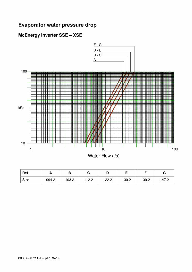
808 B – 07/11 A – pag. 34/52
Evaporator water pressure drop
McEnergy Inverter SSE – XSE
Ref A B C D E F G
Size 094.2 103.2 112.2 122.2 130.2 139.2 147.2
Water Flow (l/s)
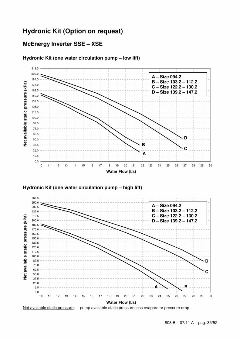
808 B – 07/11 A – pag. 35/52
Hydronic Kit (Option on request)
McEnergy Inverter SSE – XSE
Hydronic Kit (one water circulation pump – low lift)
0.0
12.5
25.0
37.5
50.0
62.5
75.0
87.5
100.0
112.5
125.0
137.5
150.0
162.5
175.0
187.5
200.0
212.5
10 11 12 13 14 15 16 17 18 19 20 21 22 23 24 25 26 27 28 29 30
A
BC
D
Hydronic Kit (one water circulation pump – high lift)
0.0
12.5
25.0
37.5
50.0
62.5
75.0
87.5
100.0
112.5
125.0
137.5
150.0
162.5
175.0
187.5
200.0
212.5
225.0
237.5
250.0
262.5
10 11 12 13 14 15 16 17 18 19 20 21 22 23 24 25 26 27 28 29 30
A B
C
D
Net available static pressure: pump available static pressure less evaporator pressure drop
Water Flow (l/s)
Net
ava
ilab
le s
tati
c p
ress
ure
(k
Pa)
Water Flow (l/s)
Net
ava
ilab
le s
tati
c p
ress
ure
(k
Pa)
A – Size 094.2 B – Size 103.2 – 112.2 C – Size 122.2 – 130.2 D – Size 139.2 – 147.2
A – Size 094.2 B – Size 103.2 – 112.2 C – Size 122.2 – 130.2 D – Size 139.2 – 147.2
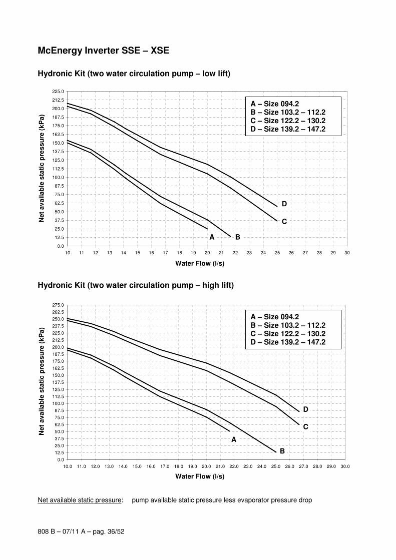
808 B – 07/11 A – pag. 36/52
McEnergy Inverter SSE – XSE
Hydronic Kit (two water circulation pump – low lift)
0.0
12.5
25.0
37.5
50.0
62.5
75.0
87.5
100.0
112.5
125.0
137.5
150.0
162.5
175.0
187.5
200.0
212.5
225.0
10 11 12 13 14 15 16 17 18 19 20 21 22 23 24 25 26 27 28 29 30
A B
C
D
Hydronic Kit (two water circulation pump – high lift)
0.0
12.5
25.0
37.5
50.0
62.5
75.0
87.5
100.0
112.5
125.0
137.5
150.0
162.5
175.0
187.5
200.0
212.5
225.0
237.5
250.0
262.5
275.0
10.0 11.0 12.0 13.0 14.0 15.0 16.0 17.0 18.0 19.0 20.0 21.0 22.0 23.0 24.0 25.0 26.0 27.0 28.0 29.0 30.0
A
B
C
D
Net available static pressure: pump available static pressure less evaporator pressure drop
Water Flow (l/s)
Net
ava
ilab
le s
tati
c p
ress
ure
(k
Pa)
A – Size 094.2 B – Size 103.2 – 112.2 C – Size 122.2 – 130.2 D – Size 139.2 – 147.2
Water Flow (l/s)
Net
ava
ilab
le s
tati
c p
ress
ure
(k
Pa)
A – Size 094.2 B – Size 103.2 – 112.2 C – Size 122.2 – 130.2 D – Size 139.2 – 147.2
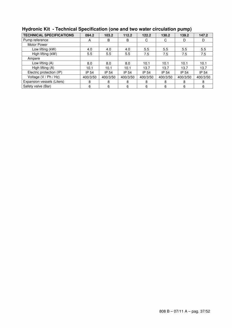
808 B – 07/11 A – pag. 37/52
Hydronic Kit - Technical Specification (one and two water circulation pump)
TECHNICAL SPECIFICATIONS 094.2 103.2 112.2 122.2 130.2 139.2 147.2
Pump reference A B B C C D D
Motor Power
Low lifting (kW) 4.0 4.0 4.0 5.5 5.5 5.5 5.5
High lifting (kW) 5.5 5.5 5.5 7.5 7.5 7.5 7.5
Ampere
Low lifting (A) 8.0 8.0 8.0 10.1 10.1 10.1 10.1
High lifting (A) 10.1 10.1 10.1 13.7 13.7 13.7 13.7
Electric protection (IP) IP 54 IP 54 IP 54 IP 54 IP 54 IP 54 IP 54
Voltage (V / Ph / Hz) 400/3/50 400/3/50 400/3/50 400/3/50 400/3/50 400/3/50 400/3/50
Expansion vessels (Liters) 8 8 8 8 8 8 8
Safety valve (Bar) 6 6 6 6 6 6 6
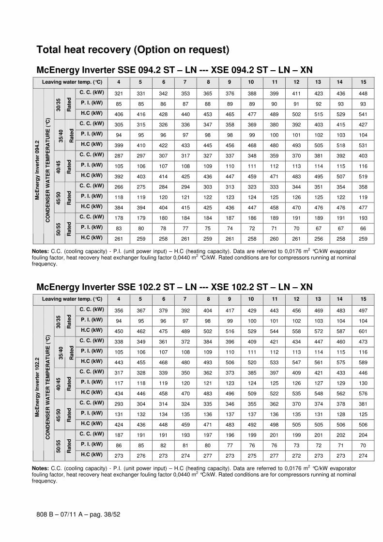
808 B – 07/11 A – pag. 38/52
Total heat recovery (Option on request)
McEnergy Inverter SSE 094.2 ST – LN --- XSE 094.2 ST – LN – XN Leaving water temp. (°C) 4 5 6 7 8 9 10 11 12 13 14 15
C. C. (kW) 321 331 342 353 365 376 388 399 411 423 436 448
P. I. (kW) 85 85 86 87 88 89 89 90 91 92 93 93
30/3
5
Rate
d
H.C (kW) 406 416 428 440 453 465 477 489 502 515 529 541
C. C. (kW) 305 315 326 336 347 358 369 380 392 403 415 427
P. I. (kW) 94 95 96 97 98 98 99 100 101 102 103 104
35/4
0
Rate
d
H.C (kW) 399 410 422 433 445 456 468 480 493 505 518 531
C. C. (kW) 287 297 307 317 327 337 348 359 370 381 392 403
P. I. (kW) 105 106 107 108 109 110 111 112 113 114 115 116
40/4
5
Rate
d
H.C (kW) 392 403 414 425 436 447 459 471 483 495 507 519
C. C. (kW) 266 275 284 294 303 313 323 333 344 351 354 358
P. I. (kW) 118 119 120 121 122 123 124 125 126 125 122 119
45/5
0
Rate
d
H.C (kW) 384 394 404 415 425 436 447 458 470 476 476 477
C. C. (kW) 178 179 180 184 184 187 186 189 191 189 191 193
P. I. (kW) 83 80 78 77 75 74 72 71 70 67 67 66
McE
nerg
y In
vert
er
094.2
CO
ND
EN
SE
R W
AT
ER
TE
MP
ER
AT
UR
E (
°C)
50/5
5
Rate
d
H.C (kW) 261 259 258 261 259 261 258 260 261 256 258 259
Notes: C.C. (cooling capacity) - P.I. (unit power input) – H.C (heating capacity). Data are referred to 0,0176 m2 °C/kW evaporator fouling factor, heat recovery heat exchanger fouling factor 0,0440 m2 °C/kW. Rated conditions are for compressors running at nominal frequency.
McEnergy Inverter SSE 102.2 ST – LN --- XSE 102.2 ST – LN – XN Leaving water temp. (°C) 4 5 6 7 8 9 10 11 12 13 14 15
C. C. (kW) 356 367 379 392 404 417 429 443 456 469 483 497
P. I. (kW) 94 95 96 97 98 99 100 101 102 103 104 104
30/3
5
Rate
d
H.C (kW) 450 462 475 489 502 516 529 544 558 572 587 601
C. C. (kW) 338 349 361 372 384 396 409 421 434 447 460 473
P. I. (kW) 105 106 107 108 109 110 111 112 113 114 115 116
35/4
0
Rate
d
H.C (kW) 443 455 468 480 493 506 520 533 547 561 575 589
C. C. (kW) 317 328 339 350 362 373 385 397 409 421 433 446
P. I. (kW) 117 118 119 120 121 123 124 125 126 127 129 130
40/4
5
Rate
d
H.C (kW) 434 446 458 470 483 496 509 522 535 548 562 576
C. C. (kW) 293 304 314 324 335 346 355 362 370 374 378 381
P. I. (kW) 131 132 134 135 136 137 137 136 135 131 128 125
45/5
0
Rate
d
H.C (kW) 424 436 448 459 471 483 492 498 505 505 506 506
C. C. (kW) 187 191 191 193 197 196 199 201 199 201 202 204
P. I. (kW) 86 85 82 81 80 77 76 76 73 72 71 70
McE
nerg
y In
vert
er
102.2
CO
ND
EN
SE
R W
AT
ER
TE
MP
ER
AT
UR
E (
°C)
50/5
5
Rate
d
H.C (kW) 273 276 273 274 277 273 275 277 272 273 273 274
Notes: C.C. (cooling capacity) - P.I. (unit power input) – H.C (heating capacity). Data are referred to 0,0176 m2 °C/kW evaporator fouling factor, heat recovery heat exchanger fouling factor 0,0440 m2 °C/kW. Rated conditions are for compressors running at nominal frequency.

808 B – 07/11 A – pag. 39/52
McEnergy Inverter SSE 113.2 ST – LN --- XSE 113.2 ST – LN – XN Leaving water temp. (°C) 4 5 6 7 8 9 10 11 12 13 14 15
C. C. (kW) 386 399 411 425 438 451 465 479 493 508 523 538
P. I. (kW) 104 105 106 107 108 109 110 111 112 113 114 115
30/3
5
Rate
d
H.C (kW) 490 504 517 532 546 560 575 590 605 621 637 653
C. C. (kW) 367 379 391 404 416 429 443 456 470 483 497 511
P. I. (kW) 115 116 117 119 120 121 122 123 125 126 127 128
35/4
0
Rate
d
H.C (kW) 482 495 508 523 536 550 565 579 595 609 624 639
C. C. (kW) 344 356 368 380 392 404 417 429 442 455 468 482
P. I. (kW) 129 130 131 132 134 135 136 138 139 140 142 143
40/4
5
Rate
d
H.C (kW) 473 486 499 512 526 539 553 567 581 595 610 625
C. C. (kW) 318 329 340 351 363 374 383 387 391 395 399 403
P. I. (kW) 145 146 147 148 150 151 150 146 142 139 135 132
45/5
0
Rate
d
H.C (kW) 463 475 487 499 513 525 533 533 533 534 534 535
C. C. (kW) 197 201 201 205 208 207 210 212 209 211 213 214
P. I. (kW) 91 90 87 86 85 82 81 80 77 76 75 74
McE
nerg
y In
vert
er
113.2
CO
ND
EN
SE
R W
AT
ER
TE
MP
ER
AT
UR
E (
°C)
50/5
5
Rate
d
H.C (kW) 288 291 288 291 293 289 291 292 286 287 288 288
Notes: C.C. (cooling capacity) - P.I. (unit power input) – H.C (heating capacity). Data are referred to 0,0176 m2 °C/kW evaporator fouling factor, heat recovery heat exchanger fouling factor 0,0440 m2 °C/kW. Rated conditions are for compressors running at nominal frequency.
McEnergy Inverter SSE 122.2 ST – LN --- XSE 122.2 ST – LN – XN Leaving water temp. (°C) 4 5 6 7 8 9 10 11 12 13 14 15
C. C. (kW) 415 429 443 457 471 486 501 516 531 546 562 578
P. I. (kW) 112 113 115 116 117 118 119 120 122 123 124 125
30/3
5
Rate
d
H.C (kW) 527 542 558 572 588 604 620 636 653 669 686 703
C. C. (kW) 394 407 420 434 448 462 476 490 505 519 534 550
P. I. (kW) 125 126 127 129 130 131 132 134 135 137 138 139
35/4
0
Rate
d
H.C (kW) 519 533 547 563 578 593 608 624 640 656 672 689
C. C. (kW) 370 382 395 408 421 434 447 461 475 489 503 517
P. I. (kW) 139 141 142 143 145 146 148 149 151 152 154 155
40/4
5
Rate
d
H.C (kW) 509 523 537 551 566 580 595 610 626 641 657 672
C. C. (kW) 341 353 365 377 387 395 402 407 411 413 417 421
P. I. (kW) 156 158 159 161 161 159 156 152 148 143 140 136
45/5
0
Rate
d
H.C (kW) 497 511 524 538 548 554 558 559 559 556 557 557
C. C. (kW) 207 209 211 212 213 216 219 219 218 219 221 222
P. I. (kW) 96 93 91 89 87 86 85 83 81 80 79 78
McE
nerg
y In
vert
er
122.2
CO
ND
EN
SE
R W
AT
ER
TE
MP
ER
AT
UR
E (
°C)
50/5
5
Rate
d
H.C (kW) 303 302 302 301 300 302 304 302 299 299 300 300
Notes: C.C. (cooling capacity) - P.I. (unit power input) – H.C (heating capacity). Data are referred to 0,0176 m2 °C/kW evaporator fouling factor, heat recovery heat exchanger fouling factor 0,0440 m2 °C/kW. Rated conditions are for compressors running at nominal frequency.
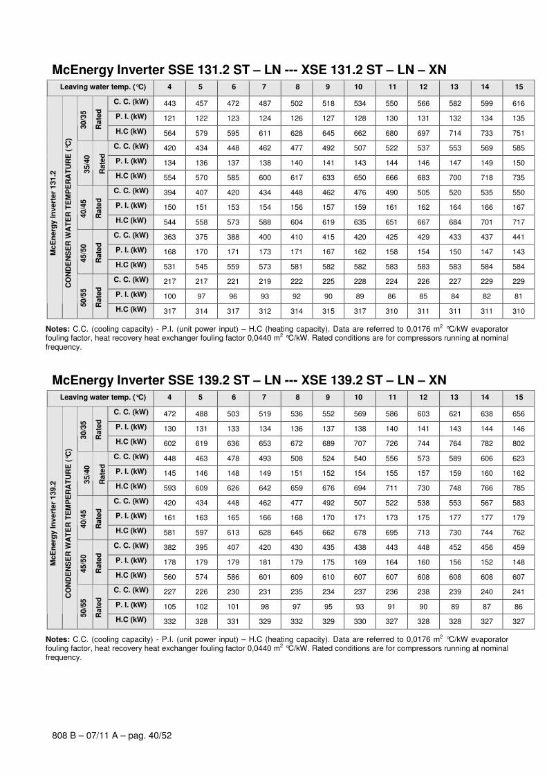
808 B – 07/11 A – pag. 40/52
McEnergy Inverter SSE 131.2 ST – LN --- XSE 131.2 ST – LN – XN Leaving water temp. (°C) 4 5 6 7 8 9 10 11 12 13 14 15
C. C. (kW) 443 457 472 487 502 518 534 550 566 582 599 616
P. I. (kW) 121 122 123 124 126 127 128 130 131 132 134 135
30/3
5
Rate
d
H.C (kW) 564 579 595 611 628 645 662 680 697 714 733 751
C. C. (kW) 420 434 448 462 477 492 507 522 537 553 569 585
P. I. (kW) 134 136 137 138 140 141 143 144 146 147 149 150
35/4
0
Rate
d
H.C (kW) 554 570 585 600 617 633 650 666 683 700 718 735
C. C. (kW) 394 407 420 434 448 462 476 490 505 520 535 550
P. I. (kW) 150 151 153 154 156 157 159 161 162 164 166 167
40/4
5
Rate
d
H.C (kW) 544 558 573 588 604 619 635 651 667 684 701 717
C. C. (kW) 363 375 388 400 410 415 420 425 429 433 437 441
P. I. (kW) 168 170 171 173 171 167 162 158 154 150 147 143
45/5
0
Rate
d
H.C (kW) 531 545 559 573 581 582 582 583 583 583 584 584
C. C. (kW) 217 217 221 219 222 225 228 224 226 227 229 229
P. I. (kW) 100 97 96 93 92 90 89 86 85 84 82 81
McE
nerg
y In
vert
er
131.2
CO
ND
EN
SE
R W
AT
ER
TE
MP
ER
AT
UR
E (
°C)
50/5
5
Rate
d
H.C (kW) 317 314 317 312 314 315 317 310 311 311 311 310
Notes: C.C. (cooling capacity) - P.I. (unit power input) – H.C (heating capacity). Data are referred to 0,0176 m2 °C/kW evaporator fouling factor, heat recovery heat exchanger fouling factor 0,0440 m2 °C/kW. Rated conditions are for compressors running at nominal frequency.
McEnergy Inverter SSE 139.2 ST – LN --- XSE 139.2 ST – LN – XN Leaving water temp. (°C) 4 5 6 7 8 9 10 11 12 13 14 15
C. C. (kW) 472 488 503 519 536 552 569 586 603 621 638 656
P. I. (kW) 130 131 133 134 136 137 138 140 141 143 144 146
30/3
5
Rate
d
H.C (kW) 602 619 636 653 672 689 707 726 744 764 782 802
C. C. (kW) 448 463 478 493 508 524 540 556 573 589 606 623
P. I. (kW) 145 146 148 149 151 152 154 155 157 159 160 162
35/4
0
Rate
d
H.C (kW) 593 609 626 642 659 676 694 711 730 748 766 785
C. C. (kW) 420 434 448 462 477 492 507 522 538 553 567 583
P. I. (kW) 161 163 165 166 168 170 171 173 175 177 177 179
40/4
5
Rate
d
H.C (kW) 581 597 613 628 645 662 678 695 713 730 744 762
C. C. (kW) 382 395 407 420 430 435 438 443 448 452 456 459
P. I. (kW) 178 179 179 181 179 175 169 164 160 156 152 148
45/5
0
Rate
d
H.C (kW) 560 574 586 601 609 610 607 607 608 608 608 607
C. C. (kW) 227 226 230 231 235 234 237 236 238 239 240 241
P. I. (kW) 105 102 101 98 97 95 93 91 90 89 87 86
McE
nerg
y In
vert
er
139.2
CO
ND
EN
SE
R W
AT
ER
TE
MP
ER
AT
UR
E (
°C)
50/5
5
Rate
d
H.C (kW) 332 328 331 329 332 329 330 327 328 328 327 327
Notes: C.C. (cooling capacity) - P.I. (unit power input) – H.C (heating capacity). Data are referred to 0,0176 m2 °C/kW evaporator fouling factor, heat recovery heat exchanger fouling factor 0,0440 m2 °C/kW. Rated conditions are for compressors running at nominal frequency.
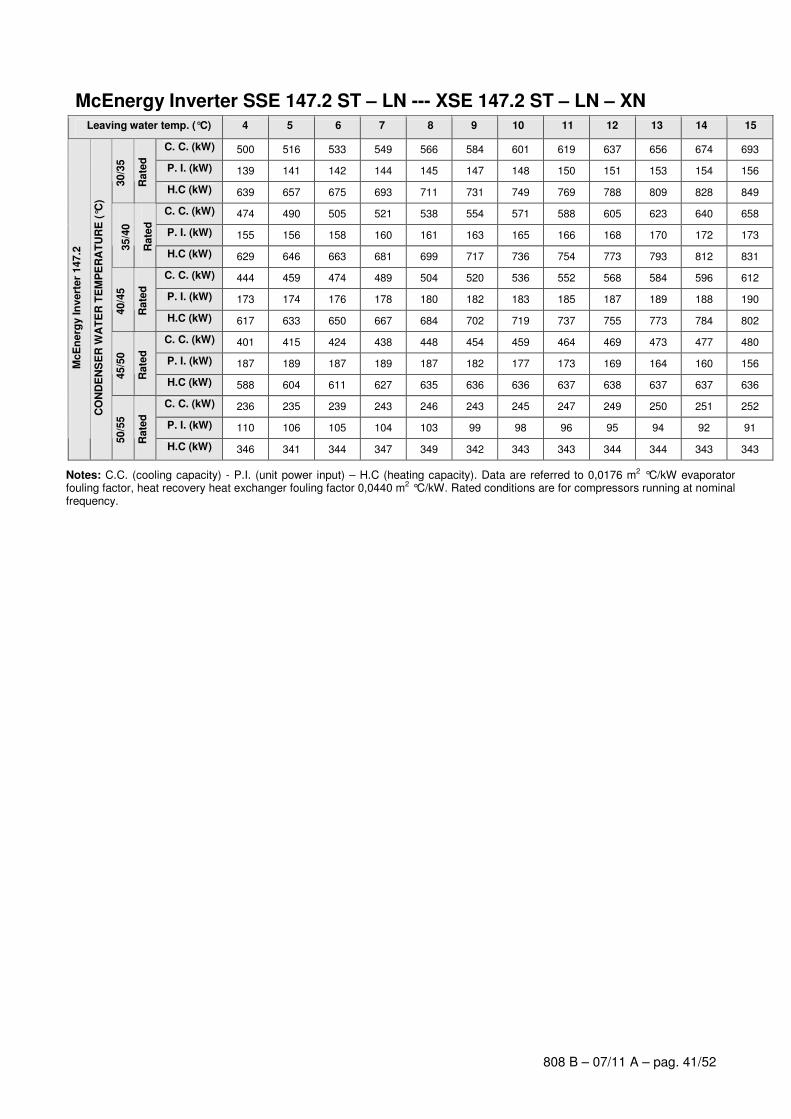
808 B – 07/11 A – pag. 41/52
McEnergy Inverter SSE 147.2 ST – LN --- XSE 147.2 ST – LN – XN Leaving water temp. (°C) 4 5 6 7 8 9 10 11 12 13 14 15
C. C. (kW) 500 516 533 549 566 584 601 619 637 656 674 693
P. I. (kW) 139 141 142 144 145 147 148 150 151 153 154 156
30/3
5
Rate
d
H.C (kW) 639 657 675 693 711 731 749 769 788 809 828 849
C. C. (kW) 474 490 505 521 538 554 571 588 605 623 640 658
P. I. (kW) 155 156 158 160 161 163 165 166 168 170 172 173
35/4
0
Rate
d
H.C (kW) 629 646 663 681 699 717 736 754 773 793 812 831
C. C. (kW) 444 459 474 489 504 520 536 552 568 584 596 612
P. I. (kW) 173 174 176 178 180 182 183 185 187 189 188 190
40/4
5
Rate
d
H.C (kW) 617 633 650 667 684 702 719 737 755 773 784 802
C. C. (kW) 401 415 424 438 448 454 459 464 469 473 477 480
P. I. (kW) 187 189 187 189 187 182 177 173 169 164 160 156
45/5
0
Rate
d
H.C (kW) 588 604 611 627 635 636 636 637 638 637 637 636
C. C. (kW) 236 235 239 243 246 243 245 247 249 250 251 252
P. I. (kW) 110 106 105 104 103 99 98 96 95 94 92 91
McE
nerg
y In
vert
er
147.2
CO
ND
EN
SE
R W
AT
ER
TE
MP
ER
AT
UR
E (
°C)
50/5
5
Rate
d
H.C (kW) 346 341 344 347 349 342 343 343 344 344 343 343
Notes: C.C. (cooling capacity) - P.I. (unit power input) – H.C (heating capacity). Data are referred to 0,0176 m2 °C/kW evaporator fouling factor, heat recovery heat exchanger fouling factor 0,0440 m2 °C/kW. Rated conditions are for compressors running at nominal frequency.
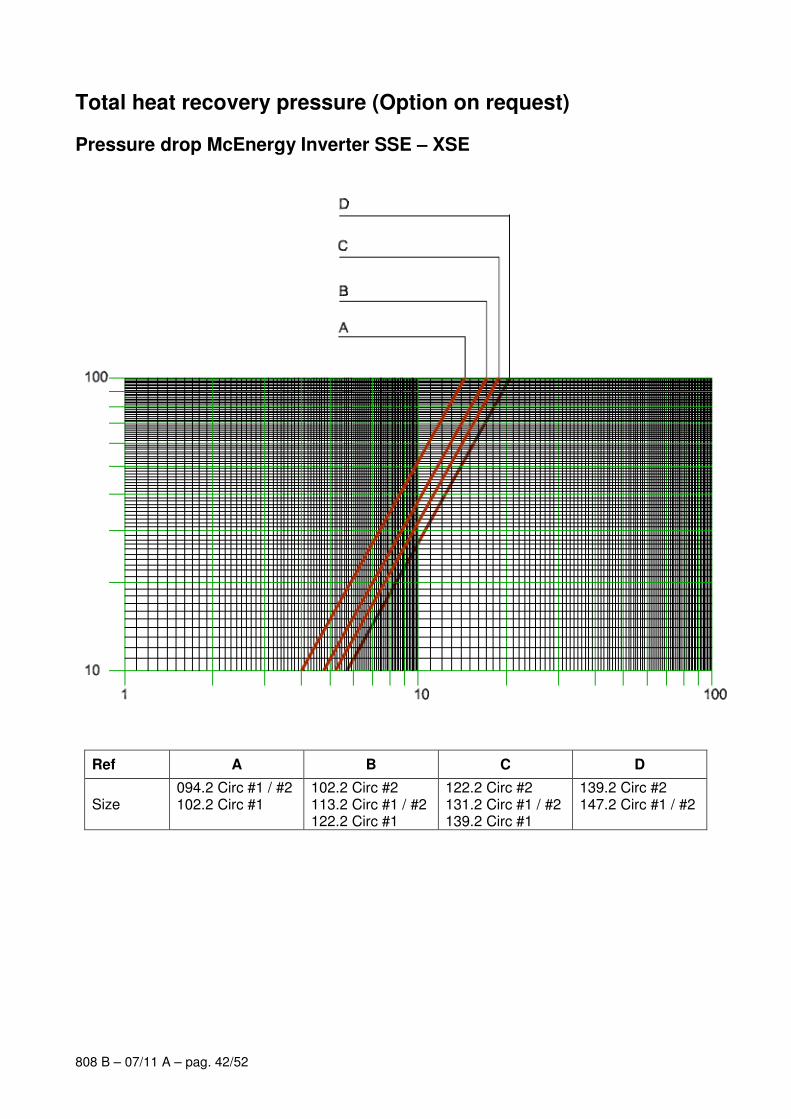
808 B – 07/11 A – pag. 42/52
Total heat recovery pressure (Option on request)
Pressure drop McEnergy Inverter SSE – XSE
Ref A B C D
Size 094.2 Circ #1 / #2 102.2 Circ #1
102.2 Circ #2 113.2 Circ #1 / #2 122.2 Circ #1
122.2 Circ #2 131.2 Circ #1 / #2 139.2 Circ #1
139.2 Circ #2 147.2 Circ #1 / #2
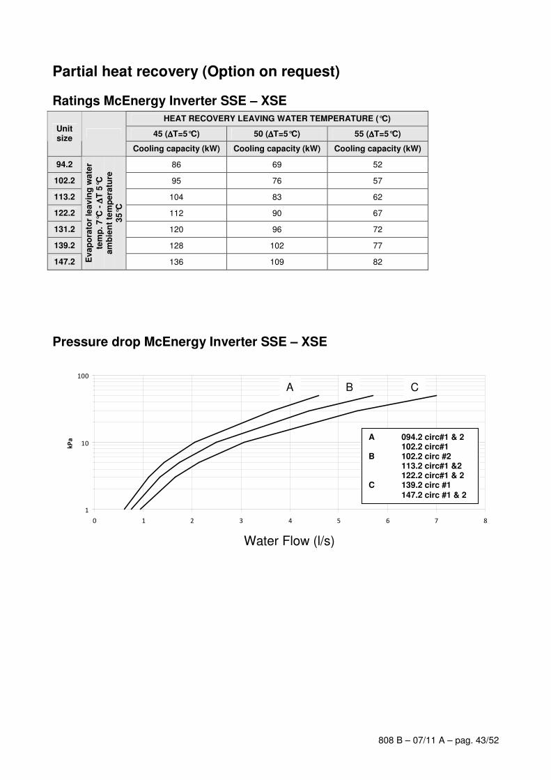
808 B – 07/11 A – pag. 43/52
Partial heat recovery (Option on request)
Ratings McEnergy Inverter SSE – XSE
HEAT RECOVERY LEAVING WATER TEMPERATURE (°C)
45 (∆∆∆∆T=5°C) 50 (∆∆∆∆T=5°C) 55 (∆∆∆∆T=5°C) Unit size
Cooling capacity (kW) Cooling capacity (kW) Cooling capacity (kW)
94.2 86 69 52
102.2 95 76 57
113.2 104 83 62
122.2 112 90 67
131.2 120 96 72
139.2 128 102 77
147.2 Ev
ap
ora
tor
lea
vin
g w
ate
r
tem
p.
7°C
- ∆∆ ∆∆
T 5
°C
am
bie
nt
tem
pe
ratu
re
35
°C
136 109 82
Pressure drop McEnergy Inverter SSE – XSE
1
10
100
0 1 2 3 4 5 6 7 8
l/s
kPa
A 094.2 circ#1 & 2 102.2 circ#1 B 102.2 circ #2
113.2 circ#1 &2 122.2 circ#1 & 2
C 139.2 circ #1 147.2 circ #1 & 2
Water Flow (l/s)
A B C
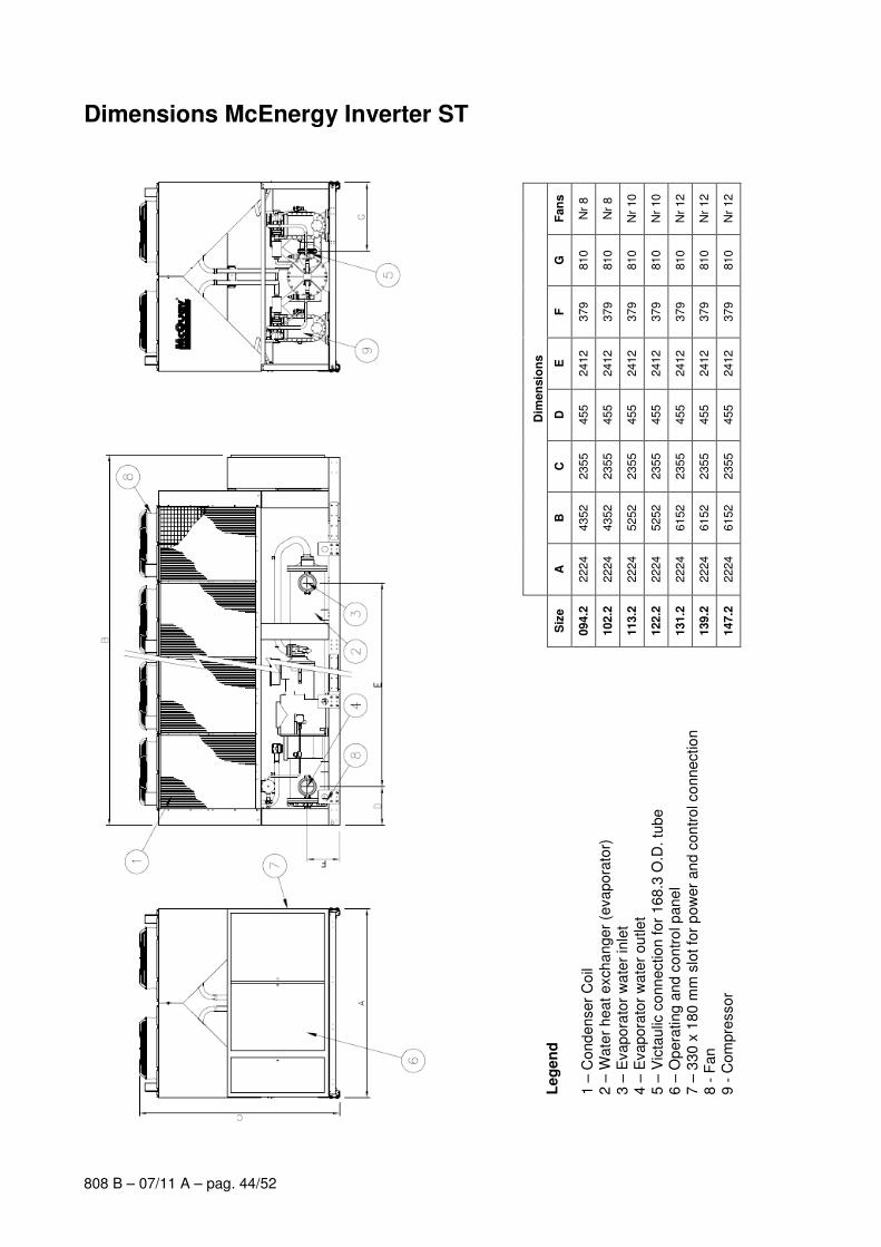
808 B – 07/11 A – pag. 44/52
Dimensions McEnergy Inverter ST
Fan
s
Nr
8
Nr
8
Nr
10
Nr
10
Nr
12
Nr
12
Nr
12
G
810
810
810
810
810
810
810
F
379
379
379
379
379
379
379
E
2412
2412
2412
2412
2412
2412
2412
D
455
455
455
455
455
455
455
C
2355
2355
2355
2355
2355
2355
2355
B
4352
4352
5252
5252
6152
6152
6152
Dim
en
sio
ns
A
2224
2224
2224
2224
2224
2224
2224
Siz
e
094.2
102.2
113.2
122.2
131.2
139.2
147.2
Leg
en
d
1 –
Cond
enser
Co
il 2 –
Wate
r hea
t excha
nger
(evapora
tor)
3 –
Evapora
tor
wa
ter
inle
t 4 –
Evapora
tor
wa
ter
ou
tle
t 5 –
Vic
taulic
conn
ectio
n for
168.3
O.D
. tu
be
6 –
Op
era
ting a
nd c
ontr
ol p
ane
l 7 –
330 x
180 m
m s
lot fo
r p
ow
er
an
d c
on
trol co
nnectio
n
8 -
Fan
9 -
Com
pre
ssor
808 B – 07/11 A – pag. 45/52
Installation notes
Warning Installation and maintenance are to be performed only by qualified personnel who are familiar with local codes and
regulations, and who are experienced with this type of equipment. Must be avoided the unit installation in places that
could be considered dangerous for all the maintenance operations.
Handling Care should be taken to avoid rough handling or shock due to dropping the unit. Do not push or pull the unit
from anything other than the base, and block the pushing vehicle away from the unit to prevent damage to the
cabinet. Never allow the unit fall during unloading or moving as this may result in serious damage. To lift the
unit, rings are provided in the base of the unit. Spreader bar and cables should be arranged to prevent damage
to the condenser coil or unit cabinet.
Location The units are produced for outside installation on roofs, floors or below ground level on condition that the area is
free from obstacles for the passage of the condenser air. The unit should be positioned on solid foundations and
perfectly level; in the case of installation on roofs or floors, it may be advisable to arrange the use of suitable
weight distribution beams. When the units are installed on the ground, a concrete base at least 250 mm wider
and longer than the unit’s footprint should be laid. Furthermore, this base should withstand the unit weight
mentioned in the technical data table.
Space requirements The units are air-cooled, hence it is important to observe the minimum distances which guarantee the best
ventilation of the condenser coils. Limitations of space reducing the air flow could cause significant reductions in
cooling capacity and an increase in electricity consumption.
To determinate unit placement, careful consideration must be given to assure a sufficient air flow across the
condenser heat transfer surface. Two conditions must be avoided to achieve the best performance: warm air
recirculation and coil starvation.
Both these conditions cause an increase of condensing pressures that results in reductions in unit efficiency and
capacity.
Moreover McQuay unique microprocessor has the ability to calculate the operating environment of the air
cooled chiller and the capacity to optimize its performance staying on-line during abnormal conditions.
Each side of the unit must be accessible after installation for periodic service. Fig.1 shows you minimum
recommended clearance requirements.
Vertical condenser air discharge must be unobstructed because the unit would have its capacity and efficiency
significantly reduced.
If the units are positioned in places surrounded by walls or obstacles of the same height as the units, the units
should be at least 2500 mm from obstacles (fig.2). In the event the obstacles are higher than the units, the units
should be at least 3000 mm from the obstacle (fig.4). Units installed closer than the minimum recommended
distance to a wall or other vertical riser may experience a combination of coil starvation and warm air
recirculation, thus causing reduction in unit capacity and efficiency reductions. Once again, the microprocessor
will allow the chiller to stay on line, producing the maximum available capacity, even at less than recommended
lateral clearances.
When two or more units are positioned side by side it is recommended that the condenser coils are at least
3600 mm distance from one another (fig.3); strong wind could be the cause of air warm recirculation.
For other installation solutions, consult McQuay technicians.
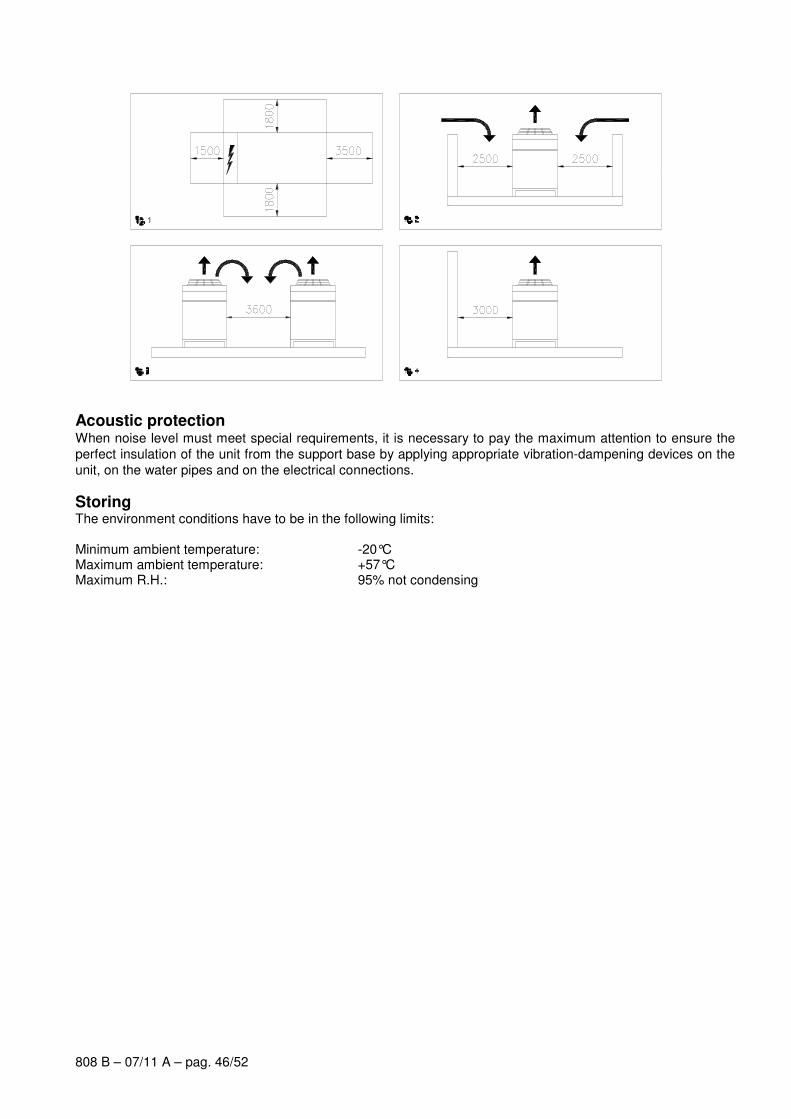
808 B – 07/11 A – pag. 46/52
Acoustic protection When noise level must meet special requirements, it is necessary to pay the maximum attention to ensure the
perfect insulation of the unit from the support base by applying appropriate vibration-dampening devices on the
unit, on the water pipes and on the electrical connections.
Storing The environment conditions have to be in the following limits: Minimum ambient temperature: -20°C Maximum ambient temperature: +57°C Maximum R.H.: 95% not condensing
808 B – 07/11 A – pag. 47/52
Specification
Technical Specification for Air Cooled Screw Chiller
GENERAL
The air cooled screw chiller will be designed and manufactured in accordance with following European directives that are equivalent to American Air-Conditioning Industry codes:
Rating of chillers EN 12055
Construction of pressure vessel PED
Electrical codes IEC 204-1 CEI 44-5 Elect. & Safety Codes
Machine Safety, Electrical Codes CEI – EN 60204 – 1
Machinery Directive 98 / 37 / EC as modified
Electromagnetic compatibility directive 89 / 336 / EEC as modified
Low-voltage Directive 73 / 23 / EEC as modified
Manufacturing Quality Standard ISO 9001:2000
The unit will be tested at full load in the factory at the nominal working conditions and water temperatures. Before shipment a full test will be held to avoid any losses. Chiller will be delivered to the job site completely assembled and charged with right refrigerant and oil quantity. Comply with the manufacturer instructions for rigging and handling equipment. The unit will be able to start up and operate as standard at full load and outside air temperature from .… °C to .… °C with an evaporator leaving fluid temperature between …. °C and 15 °C All unit’s published performances have to be certified by Eurovent.
REFRIGERANT
Only HFC 134a will be accepted.
PERFORMANCE
� Number of air cooled screw chiller: ...............
� Cooling capacity for single air cooled screw chiller: ............... kW
� Power input for single air cooled screw chiller in cooling mode: ............... kW
� Shell & tube heat exchanger entering water temperature in cooling mode: ............... °C
� Shell & tube heat exchanger leaving water temperature in cooling mode: ............... °C
� Shell & tube heat exchanger water flow: ............... l/s
� Nominal outside working ambient temperature in cooling mode: ............... °C
� The unit should work with electricity in range 400V ±10%, 3ph, 50Hz without neutral and shall only have one power connection point.
UNIT DESCRIPTION
Chiller shall include as standard not less than: two independent refrigerant circuits, semi-hermetic rotary single screw compressors, air–cooled variable electrical frequency driver for each compressor (VFD), electronic expansion device (EEXV), refrigerant direct expansion shell & tube heat exchanger, air-cooled condenser section, R134a refrigerant, lubrication system, motor starting components, suction line shut-off valve, discharge line shut-off valve, control system and all components necessary for safe and stable unit operation.
Chiller will be factory assembled on a robust base-frame made of zinc coated steel, protected by an epoxy paint.
NOISE LEVEL AND VIBRATIONS
Sound pressure level at 1 meter distance in free field, semispheric conditions, shall not exceed ………dB(A).
The sound pressure levels must be rated in accordance to ISO 3744.
Other types of rating unacceptable. Vibration level should not exceed 2 mm/s.
808 B – 07/11 A – pag. 48/52
DIMENSIONS
Unit dimensions shall not exceed following indications:
� unit length ............... mm,
� unit width ............... mm,
� unit height ............... mm.
CHILLER COMPONENTS
Compressors
� Semi-hermetic, single-screw type with one main helical rotor meshing with gaterotor. The gaterotor will
be constructed of a carbon impregnated engineered composite material. The gaterotor supports will be
constructed of cast iron.
� The oil injection shall be used in order to get high EER (Energy Efficiency Ratio) also at high
condensing pressure and low sound pressure levels in each load condition.
� Refrigerant system differential pressure shall provide oil flow throught service replaceble, 0.5 micron,
full flow, cartridge type oil filter internal to compressor.
� Refrigerant system differential pressure shall provide oil injection on all moving compressor parts to
correctly lubricate them. Electrical oil pump lubricating system is not acceptable.
� The compressor’s oil cooling must be realized, when necessary, by refrigerant liquid injection. External
dedicated heat exchanger and additional piping to carry the oil from the compressor to heat exchanger
and viceversa will be not accepted.
� The compressor shall be provided with an integrated, high efficiency, cyclonic type oil separator and
with built-in oil filter, cartridge type.
� The compressor shall be direct electrical driven, without gear transmission between the screw and the
electrical motor.
� The compressor casing shall be provided with ports to realize economized refrigerant cycles.
� Shall be present two thermal protection realized by a thermistor for high temperature protection: one
temperature sensor to protect electrical motor and another sensor to protect unit and lubricating oil from
high discharge gas temperature.
� The compressor shall be equipped with an electric oil-crankcase heater.
� Compressor shall be fully field serviceable. Compressor that must be removed and returned to the
factory for service shall be unacceptable.
Cooling capacity control system
� Each unit will have a microprocessor for the control of compressor slide valve’s position and the instantaneous RPM value of the motor.
� The unit capacity control shall be infinitely modulating, from 100% down to 27% for each circuit (from 100% down to 13,5% of full load for unit with 2 compressors). The chiller shall be capable of stable operation to a minimum of 13,5% of full load without hot gas bypass.
� Step unloading unacceptable because of evaporator leaving water temperature fluctuation and low unit efficiency at partial load.
� The system shall stage the unit based on the leaving evaporator water temperature that shall be controlled by a PID (Proportional Integral Derivative) loop.
� Unit control logic shall to manage frequency level of the compressor electric motor to exactly match plant load request in order to keep constant the set point for delivered chilled water temperature. In this operating condition unit control logic shall modulate electrical frequency level in a range lower and upper the nominal electrical network value fixed at 50 Hz.
� The microprocessor unit control shall detect conditions that approach protective limits and take self-corrective action prior to an alarm occurring. The system shall automatically reduce chiller capacity when any of the following parameters are outside their normal operating range:
o High condenser pressure
o Low evaporation refrigerant temperature
o High compressor motor amps
808 B – 07/11 A – pag. 49/52
Unit-Mounted Variable Frequency Driver (VFD) and Electrical Requirement
� All interconnecting wiring between the VFD and the chiller shall be factory-installed. Customer electrical connection for compressor motor power shall be limited to main power leads to the single point power connection located into electrical panel.
� The VFD shall be air cooled type. Water cooled design or refrigerant cooled design are not acceptable.
� The VFD full load efficiency shall meet or exceed 97% at 100% VFD rated ampacity.
� Base motor frequency shall permit motor to be utilized at nameplate voltage. Adjustable frequency range, monitored by unit’s microprocessor control, shall permit a stable unit capacity control down to 13.5% without hot-gas bypass.
� Starting current for the compressor shall not exceed nominal compressor load amps.
� Unit displacement power factor shall be not less than 0.95 on entire unit capacity range, from 100% down to 13,5%
Evaporator
� The units shall be supplied with shell and tubes counter-flow heat exchanger with single refrigerant
pass. It will be refrigerant direct expansion type with refrigerant inside the tubes and water outside (shell
side). It will include carbon steel tube sheets, with straight copper tubes internally wound for higher
efficiencies, expanded on the tube plates.
� The external shell shall be linked with an electrical heater to prevent freezing down to -28°C ambient
temperature, commanded by a thermostat and shall be insulated with flexible, closed cell polyurethane
insulation material (10-mm thick).
� The evaporator will have 2 circuits, one for each compressor and shall be single refrigerant pass.
� The water connections shall be VICTAULIC type connections as standard to ensure quick mechanical
disconnection between the unit and the hydronic network.
� Evaporator is manufactured in accordance to PED approval.
Condenser coil
� The condenser coils are constructed with internally finned seamless copper tubes having a "W"
configuration and arranged in a staggered row pattern and mechanically expanded into lanced and
rippled aluminium fins with full fin collars for higher efficiencies. The space between the fins are given
by a collar that will increase the surface area in connection with the tubes, protecting them from ambient
corrosion.
� The coils will have an integral subcooler circuit that provides sufficient subcooling to effectively eliminate
the possibility of liquid flashing and increase the unit's efficiency of 5-7% without increasing in power
absorption.
� The condenser coil shall be leak-tested and submitted to a pressure test with dry air.
Condenser fans
� The fans used in conjunction with the condenser coils, shall be helical type with aerofoil blades for
higher efficiencies and lower noise. Each fan shall be protected by a fan guard.
� The air discharge shall be vertical and each fan must be coupled to the electrical motor, supplied as
standard to IP54 and capable to work to ambient temperatures of - 20°C to + 55°C.
� They shall have individual overload protection via a circuit breaker switch.
Refrigerant circuit
� The unit must have refrigerant circuits completely independent of each other with one compressor and one variable electrical frequency driver per circuit (VFD).
� Each circuit shall include as standard: electronic expansion device piloted by unit’s microprocessor control, compressor discharge shut-off valve, suction line shut-off valve, replaceable core filter-drier, sight glass with moisture indicator and insulated suction line.
808 B – 07/11 A – pag. 50/52
Condensation control
� The units will be provided with an automatic control for condensing pressure which ensures the working at low external temperatures down to -10 °C, thanks the Inverter of the condenser fans, to maintain condensing pressure.
� Automatic compressor unloading when abnormal high condensing pressure is detected to prevent the shutdown of the refrigerant circuit (shutdown of the unit) due to a high-pressure fault.
Low Noise unit options (on request)
� The unit compressors shall be connected with unit’s metal baseframe by rubber antivibration supports
to prevent the transmission of vibrations to all metal unit structure and so to control the unit noise.
� The suction lines shall be provided with mufflers to eliminate vibration and so to reduce the noise unit
emission.
� The chiller shall be provided with an acoustically compressor enclosure. This enclosure shall be
realized with a light, corrosion resisting aluminium structure and metal panels. The compressors sound-
proof enclosure shall be internally fitted with flexible, multi layer, high density materials. The middle
layer is 3 mm, very high density and high efficiency noise reduction material. The enclosure shall be
carefully assembled to avoid decreasing of its noise reduction power.
Hydronic kit options (on request)
� The hydronic module shall be integrated in the chiller chassis without increasing its dimensions and
include the following elements: expansion vessel, centrifugal monocell water pump with three-phase
motor equipped with internal over-temperature protection, safety relief valve, filling kit.
� The water piping shall be protected against corrosion and equipped with drain and purge plugs. The
customer connections shall be Victaulic connections. The piping shall be fully insulated to prevent
condensation (pump insulation using polyurethane foam).
� A choice of four pump types shall be available:
o in-line single high-pressure pump or
o in-line dual high-pressure pump (only for unit without compressor sound proof cabinet) or
o in-line single low-pressure pump or
o in-line dual low-pressure pump (only for unit without compressor sound proof cabinet)
Control panel
� Field power connection, control interlock terminals, and unit control system should be centrally located in an electric panel (IP 54). Power and starting controls should be separate from safety and operating controls in different compartments of the same panel.
� Starting will be Inverter type.
� Operating and safety controls should include energy saving control; emergency stop switch; overload protection for compressor motor; high and low pressure cut-out switch (for each refrigerant circuit); anti-freeze thermostat; cut-out switch for each compressor.
� All of the information regarding the unit will be reported on a display and with the internal built-in calendar and clock that will switch the unit ON/OFF during day time all year long.
� The following features and functions shall be included:
- resetting chilled water temperature by controlling the return water temperature or by a remote 4-20 mA DC signal or by controlling the external ambient temperature;
- soft load function to prevent the system from operating at full load during the chilled fluid pulldown period;
- password protection of critical parameters of control; - start-to-start and stop-to-star timers to provide minimum compressor off-time with maximum motor
protection; - communication capability with a PC or remote monitoring; - discharge pressure control through intelligent cycling of condenser fans; - lead-lag selection by manual or automatically by circuit run hours; - double set point for brine unit version;
808 B – 07/11 A – pag. 51/52
- scheduling via internal time clock to allow programming of a yearly start-stop schedule accommodating weekends and holidays.
Optional High Level Communications Interface
The controller as a minimum shall be capable of providing the data shown in the above list and document entitled McQuaycomms, using the following options: -
Option A RS485 Serial card Option B RS232 Serial card
Option C LonWorks interface to FTT10A Transceiver. Option D Bacnet Compatible
Option E Use of Compass Points (manufactured by North Communications) to allow communications with Such as Honeywell, Satchwell, Johnson Controls, Trend etc.
808 B – 07/11 A – pag. 52/52
“The present publication is drawn up by of information only and does not constitute an offer binding upon McQuay. McQuay has compiled the content of this publication to the best of its knowledge. No express or implied warranty is given for the completeness, accuracy, reliability or fitness for particular purpose of its content, and the products and services presented therein. Specification are subject to change without prior notice. McQuay explicitly rejects any liability for any direct or indirect damage, in the broadest sense, arising from or related to the use and/or interpretation of this publication. All content is copyrighted by McQuay.”
McQuay Italia S.P.A.
S.S. Nettunense, km 12+300 – 00040 Cecchina (Roma) Italia – Tel. (06) 937311 – Fax (06) 9374014 – E-mail: info @mcquayeurope. com
Web site: www .mcquayeurope. com
McQuay is participating in the Eurovent
Certification Programme
Product are as listed in the Eurovent
Directory of Certified Products
Certificazione Eurovent.
I prodotti interessati figurano nella Guida
Eurovent dei Prodotti Certificati.
McQuay partecipa al programma di