Embed Size (px)
Citation preview
General-Purpose AC Servo
MODEL
MR-J2-03B5SERVO AMPLIFIERINSTRUCTION MANUAL
SSCNET Compatible
B
J2-Jr Series
A - 1
Safety Instructions (Always read these instructions before using the equipment.)
Do not attempt to install, operate, maintain or inspect the servo amplifier and servo motor until you have readthrough this Instruction Manual, Installation guide, Servo motor Instruction Manual and appended documentscarefully and can use the equipment correctly. Do not use the servo amplifier and servo motor until you have afull knowledge of the equipment, safety information and instructions.In this Instruction Manual, the safety instruction levels are classified into "WARNING" and "CAUTION".
WARNING Indicates that incorrect handling may cause hazardous conditions,resulting in death or severe injury.
CAUTION Indicates that incorrect handling may cause hazardous conditions,resulting in medium or slight injury to personnel or may cause physicaldamage.
Note that the CAUTION level may lead to a serious consequence according to conditions. Please follow theinstructions of both levels because they are important to personnel safety.What must not be done and what must be done are indicated by the following diagrammatic symbols:
: Indicates what must not be done. For example, "No Fire" is indicated by .
: Indicates what must be done. For example, grounding is indicated by .
In this Instruction Manual, instructions at a lower level than the above, instructions for other functions, and soon are classified into "POINT".After reading this installation guide, always keep it accessible to the operator.
A - 2
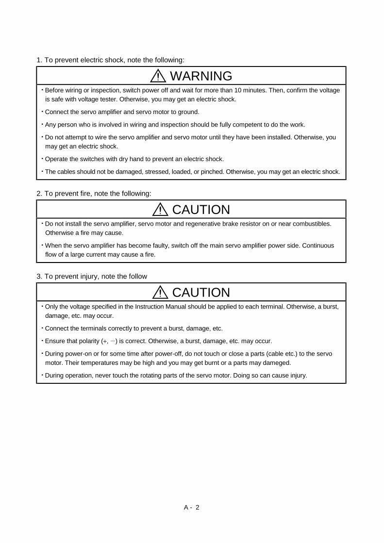
1. To prevent electric shock, note the following:
WARNINGBefore wiring or inspection, switch power off and wait for more than 10 minutes. Then, confirm the voltageis safe with voltage tester. Otherwise, you may get an electric shock.
Connect the servo amplifier and servo motor to ground.
Any person who is involved in wiring and inspection should be fully competent to do the work.
Do not attempt to wire the servo amplifier and servo motor until they have been installed. Otherwise, youmay get an electric shock.
Operate the switches with dry hand to prevent an electric shock.
The cables should not be damaged, stressed, loaded, or pinched. Otherwise, you may get an electric shock.
2. To prevent fire, note the following:
CAUTIONDo not install the servo amplifier, servo motor and regenerative brake resistor on or near combustibles.Otherwise a fire may cause.
When the servo amplifier has become faulty, switch off the main servo amplifier power side. Continuousflow of a large current may cause a fire.
3. To prevent injury, note the follow
CAUTIONOnly the voltage specified in the Instruction Manual should be applied to each terminal. Otherwise, a burst,damage, etc. may occur.
Connect the terminals correctly to prevent a burst, damage, etc.
Ensure that polarity ( , ) is correct. Otherwise, a burst, damage, etc. may occur.
During power-on or for some time after power-off, do not touch or close a parts (cable etc.) to the servomotor. Their temperatures may be high and you may get burnt or a parts may dameged.
During operation, never touch the rotating parts of the servo motor. Doing so can cause injury.
A - 3
4. Additional instructionsThe following instructions should also be fully noted. Incorrect handling may cause a fault, injury, electricshock, etc.
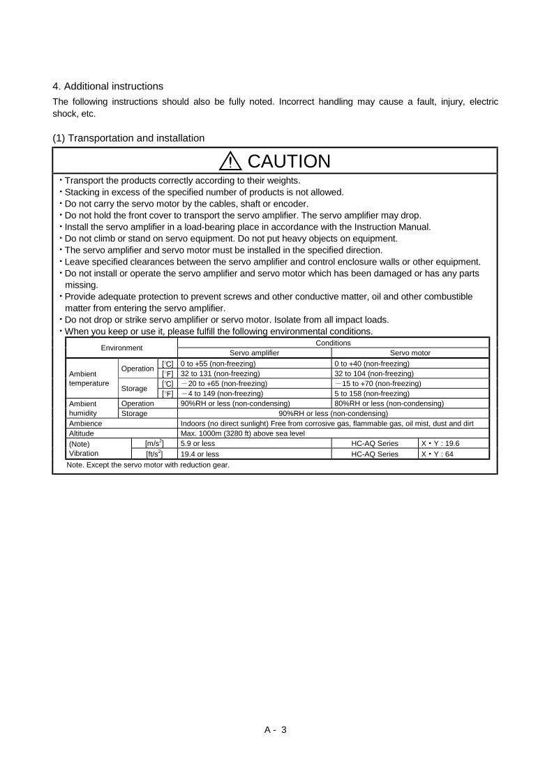
(1) Transportation and installation
CAUTIONTransport the products correctly according to their weights.Stacking in excess of the specified number of products is not allowed.Do not carry the servo motor by the cables, shaft or encoder.Do not hold the front cover to transport the servo amplifier. The servo amplifier may drop.Install the servo amplifier in a load-bearing place in accordance with the Instruction Manual.Do not climb or stand on servo equipment. Do not put heavy objects on equipment.The servo amplifier and servo motor must be installed in the specified direction.Leave specified clearances between the servo amplifier and control enclosure walls or other equipment.Do not install or operate the servo amplifier and servo motor which has been damaged or has any partsmissing.Provide adequate protection to prevent screws and other conductive matter, oil and other combustiblematter from entering the servo amplifier.Do not drop or strike servo amplifier or servo motor. Isolate from all impact loads.When you keep or use it, please fulfill the following environmental conditions.
ConditionsEnvironment Servo amplifier Servo motor[ ] 0 to 55 (non-freezing) 0 to 40 (non-freezing)Operation [ ] 32 to 131 (non-freezing) 32 to 104 (non-freezing)[ ] 20 to 65 (non-freezing) 15 to 70 (non-freezing)
Ambienttemperature
Storage [ ] 4 to 149 (non-freezing) 5 to 158 (non-freezing)Operation 90%RH or less (non-condensing) 80%RH or less (non-condensing)Ambient
humidity Storage 90%RH or less (non-condensing)Ambience Indoors (no direct sunlight) Free from corrosive gas, flammable gas, oil mist, dust and dirtAltitude Max. 1000m (3280 ft) above sea level
[m/s2] 5.9 or less HC-AQ Series X Y : 19.6(Note)Vibration [ft/s2] 19.4 or less HC-AQ Series X Y : 64
Note. Except the servo motor with reduction gear.
A - 4
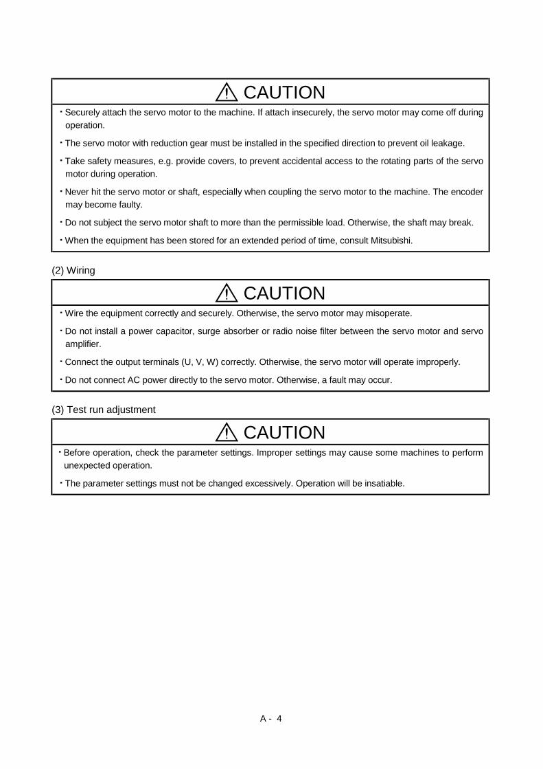
CAUTIONSecurely attach the servo motor to the machine. If attach insecurely, the servo motor may come off duringoperation.
The servo motor with reduction gear must be installed in the specified direction to prevent oil leakage.
Take safety measures, e.g. provide covers, to prevent accidental access to the rotating parts of the servomotor during operation.
Never hit the servo motor or shaft, especially when coupling the servo motor to the machine. The encodermay become faulty.
Do not subject the servo motor shaft to more than the permissible load. Otherwise, the shaft may break.
When the equipment has been stored for an extended period of time, consult Mitsubishi.
(2) Wiring
CAUTIONWire the equipment correctly and securely. Otherwise, the servo motor may misoperate.
Do not install a power capacitor, surge absorber or radio noise filter between the servo motor and servoamplifier.
Connect the output terminals (U, V, W) correctly. Otherwise, the servo motor will operate improperly.
Do not connect AC power directly to the servo motor. Otherwise, a fault may occur.
(3) Test run adjustment
CAUTIONBefore operation, check the parameter settings. Improper settings may cause some machines to performunexpected operation.
The parameter settings must not be changed excessively. Operation will be insatiable.
A - 5
(4) Usage
CAUTIONProvide a forced stop circuit to ensure that operation can be stopped and power switched off immediately.
Any person who is involved in disassembly and repair should be fully competent to do the work.
Before resetting an alarm, make sure that the run signal is off to prevent an accident. A sudden restart ismade if an alarm is reset with the run signal on.
Do not modify the equipment.
Use a noise filter, etc. to minimize the influence of electromagnetic interference, which may be caused byelectronic equipment used near the servo amplifier.
Use the servo amplifier with the specified servo motor.
The electromagnetic brake on the servo motor is designed to hold the motor shaft and should not be usedfor ordinary braking.
For such reasons as service life and mechanical structure (e.g. where a ballscrew and the servo motorare coupled via a timing belt), the electromagnetic brake may not hold the servo motor shaft. To ensuresafety, install a stopper on the machine side.
(5) Corrective actions
CAUTIONWhen it is assumed that a hazardous condition may take place at the occur due to a power failure or aproduct fault, use a servo motor with electromagnetic brake or an external brake mechanism for thepurpose of prevention.
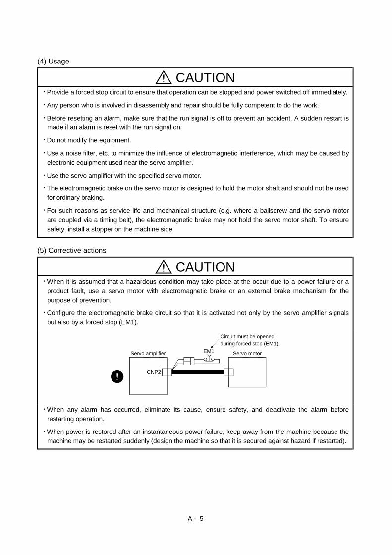
Configure the electromagnetic brake circuit so that it is activated not only by the servo amplifier signalsbut also by a forced stop (EM1).
CNP2
EM1 Servo amplifier
Circuit must be openedduring forced stop (EM1).
Servo motor
When any alarm has occurred, eliminate its cause, ensure safety, and deactivate the alarm beforerestarting operation.
When power is restored after an instantaneous power failure, keep away from the machine because themachine may be restarted suddenly (design the machine so that it is secured against hazard if restarted).
A - 6
(6) Maintenance, inspection and parts replacement
CAUTIONWith age, the electrolytic capacitor will deteriorate. To prevent a secondary accident due to a fault, it isrecommended to replace the electrolytic capacitor every 10 years when used in general environment.
(7) General instructionTo illustrate details, the equipment in the diagrams of this Instruction Manual may have been drawnwithout covers and safety guards. When the equipment is operated, the covers and safety guards mustbe installed as specified. Operation must be performed in accordance with this Instruction Manual.
About processing of waste When you discard servo amplifier, a battery (primary battery), and other option articles, please follow the law ofeach country (area).
FOR MAXIMUM SAFETYThis product is not designed or manufactured to be used in equipment or systems in situations that canaffect or endanger human life.When considering this product for operation in special applications such as machinery or systems used inpassenger transportation, medical, aerospace, atomic power, electric power, or submarine repeatingapplications, please contact your nearest Mitsubishi sales representative.Although this product was manufactured under conditions of strict quality control, you are strongly advisedto install safety devices to forestall serious accidents when it is used in facilities where a breakdown in theproduct is likely to cause a serious accident.
EEP-ROM lifeThe number of write times to the EEP-ROM, which stores parameter settings, etc., is limited to 100,000. Ifthe total number of the following operations exceeds 100,000, the servo amplifier and/or converter unit mayfail when the EEP-ROM reaches the end of its useful life.
Write to the EEP-ROM due to parameter setting changes
A - 7
COMPLIANCE WITH EC DIRECTIVES1. WHAT ARE EC DIRECTIVES?The EC directives were issued to standardize the regulations of the EU countries and ensure smoothdistribution of safety-guaranteed products. In the EU countries, the machinery directive (effective inJanuary, 1995), EMC directive (effective in January, 1996) and low voltage directive (effective in January,1997) of the EC directives require that products to be sold should meet their fundamental safetyrequirements and carry the CE marks (CE marking). CE marking applies to machines and equipmentinto which servo amplifiers have been installed.
(1) EMC directiveThe EMC directive applies not to the servo units alone but to servo-incorporated machines andequipment. For specific EMC directive conforming methods, refer to the EMC Installation Guidelines(IB(NA)67310).This servo has been confirmed to be compliant with the EMC Directives in the compliance methodgiven in the EMC Installation Guidelines.
(2) Low voltage directiveThe low voltage directive applies also to servo units alone. Hence, they are designed to comply withthe low voltage directive.This servo is certified by TUV, third-party assessment organization, to comply with the low voltagedirective.
(3) Machine directiveNot being machines, the servo amplifiers need not comply with this directive.
2. PRECAUTIONS FOR COMPLIANCEThe standard models of the servo amplifier and servo motor comply with the EN standard.In addition to the precautions for compliance with the EN standard provided in this manual, strictlyfollow the items given below. Where there is no specific explanation of EN standard compliance, thespecifications are the same as those of the standard models.
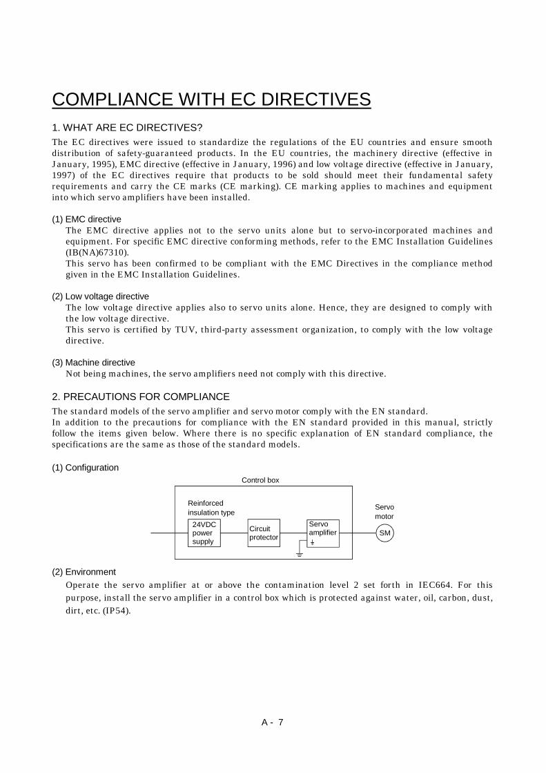
(1) Configuration
24VDCpowersupply
Circuitprotector
Reinforcedinsulation type
Servoamplifier
Servomotor
SM
Control box
(2) EnvironmentOperate the servo amplifier at or above the contamination level 2 set forth in IEC664. For thispurpose, install the servo amplifier in a control box which is protected against water, oil, carbon, dust,dirt, etc. (IP54).
A - 8
(3) Power supplyUse a 24VDC power supply which has been insulation-reinforced in I/O.
(4) GroundingTo prevent an electric shock, always connect the protective earth terminal (E) to the servo amplifierand always connect it to the earth (E) of the control box.
(5) Auxiliary equipment and options(a) The circuit protector used should be the EN or IEC standard-compliant products of the models
described in Section 11.2.2.
(b) The sizes of the cables described in Section 11.2.1 meet the following requirements. To meet theother requirements, follow Table 5 and Appendix C in EN60204-1.
Ambient temperature: 40 (104) [ ( )]Sheath: PVC (polyvinyl chloride)Installed on wall surface or open table tray
(6) Performing EMC testsWhen EMC tests are run on a machine/device into which the servo amplifier has been installed, itmust conform to the electromagnetic compatibility (immunity/emission) standards after it hassatisfied the operating environment/electrical equipment specifications.For the other EMC directive guidelines on the servo amplifier, refer to the EMC InstallationGuidelines(IB(NA)67310).
A - 9
CONFORMANCE WITH UL/C-UL STANDARDThe standard models of the servo amplifier and servo motor comply with the UL/C-UL Standard.Unless otherwise specified, the handling, performance, specifications, etc. of the UL/C-UL Standard-compliant models are the same as those of the standard models.When using 24VDC power supply, options and auxiliary equipment, use those which conform to theUL/C-UL Standard.
<<About the manuals>>
This Instruction Manual and the MELSERVO Servo Motor Instruction Manual are required if you usethe General-Purpose AC servo MR-J2-03B5 for the first time. Always purchase them and use the MR-J2-03B5 safely.Also read the manual of the servo system controller.For the flange size of the machine side where the servo motor is installed, refer to "CONFORMANCEWITH UL/C-UL STANDARD" in the Servo Motor Instruction Manual.
Relevant manuals
Manual name Manual No.MELSERVO-J2-Jr Series To Use the AC Servo Safely(Packed with the servo amplifier)
IB(NA)67426
MELSERVO Servo Motor Instruction Manual SH(NA)3181EMC Installation Guidelines IB(NA)67310

A - 10
MEMO
1
CONTENTS
1. FUNCTIONS AND CONFIGURATION 1- 1 to 1- 6
1.1 Introduction.............................................................................................................................................. 1- 11.2 Servo amplifier standard specifications ................................................................................................ 1- 21.3 Function list ............................................................................................................................................. 1- 21.4 Model code definition .............................................................................................................................. 1- 31.5 Combination with servo motor............................................................................................................... 1- 31.6 Parts identification.................................................................................................................................. 1- 41.7 Servo system with auxiliary equipment................................................................................................ 1- 5
2. INSTALLATION 2- 1 to 2- 6
2.1 Environmental conditions....................................................................................................................... 2- 12.2 Installation direction and clearances .................................................................................................... 2- 22.3 Keep out foreign materials ..................................................................................................................... 2- 32.4 Cable stress .............................................................................................................................................. 2- 42.5 Using the DIN rail for installation ........................................................................................................ 2- 5
3. SIGNALS AND WIRING 3- 1 to 3-18
3.1 Connection example of control signal system....................................................................................... 3- 23.2 I/O signals................................................................................................................................................. 3- 4
3.2.1 Connectors and signal arrangements............................................................................................. 3- 43.2.2 Signal explanations .......................................................................................................................... 3- 5
3.3 Alarm occurrence timing chart .............................................................................................................. 3- 63.4 Interfaces.................................................................................................................................................. 3- 7
3.4.1 Common line ..................................................................................................................................... 3- 73.4.2 Detailed description of the interfaces ............................................................................................. 3- 8
3.5 Input power supply circuit...................................................................................................................... 3- 93.5.1 Connection example.......................................................................................................................... 3- 93.5.2 Explanation of signals..................................................................................................................... 3-103.5.3 Power-on sequence........................................................................................................................... 3-10
3.6 Servo motor with electromagnetic brake ............................................................................................. 3-123.7 Grounding................................................................................................................................................ 3-153.8 Instructions for the 3M connector......................................................................................................... 3-173.9 Control axis selection ............................................................................................................................. 3-18
4. OPERATION AND DISPLAY 4- 1 to 4- 8
4.1 When switching power on for the first time.......................................................................................... 4- 14.2 Start up..................................................................................................................................................... 4- 24.3 Servo amplifier display ........................................................................................................................... 4- 44.4 Test operation mode ................................................................................................................................ 4- 6
2
5. PARAMETERS 5- 1 to 5- 8
5.1 Parameter write inhibit .......................................................................................................................... 5- 15.2 Lists........................................................................................................................................................... 5- 1
6. ADJUSTMENT 6- 1 to 6-10
6.1 What is gain adjustment?....................................................................................................................... 6- 16.1.1 Difference between servo amplifier and other drives ................................................................... 6- 16.1.2 Basics of the servo system ............................................................................................................... 6- 2
6.2 Gain adjustment ...................................................................................................................................... 6- 36.2.1 Parameters required for gain adjustment...................................................................................... 6- 36.2.2 Block diagram ................................................................................................................................... 6- 36.2.3 What is auto tuning? ........................................................................................................................ 6- 4
6.3 Gain adjustment by auto tuning............................................................................................................ 6- 56.3.1 Adjustment method .......................................................................................................................... 6- 56.3.2 Valid conditions................................................................................................................................. 6- 5
6.4 Manual gain adjustment......................................................................................................................... 6- 66.4.1 When machine rigidity is low .......................................................................................................... 6- 66.4.2 When the machine vibrates due to machine resonance frequency.............................................. 6- 76.4.3 Load inertia moment is 20 or more times ...................................................................................... 6- 86.4.4 When shortening the settling time ................................................................................................. 6- 96.4.5 When the same gain is used for two or more axes ....................................................................... 6-10
6.5 Slight vibration suppression control..................................................................................................... 6-10
7. INSPECTION 7- 1 to 7- 2
8. TROUBLESHOOTING 8- 1 to 8- 8
8.1 Alarms and warning list ......................................................................................................................... 8- 18.2 Remedies for alarms................................................................................................................................ 8- 28.3 Remedies for warnings............................................................................................................................ 8- 7
9. OUTLINE DIMENSION DRAWINGS 9- 1 to 9- 6
9.1 Servo amplifiers....................................................................................................................................... 9- 19.2 Connectors................................................................................................................................................ 9- 2
10. CHARACTERISTICS 10- 1 to 10- 4
10.1 Overload protection characteristics ................................................................................................... 10- 110.2 Dynamic brake characteristics........................................................................................................... 10- 210.3 Motor cable flexing life........................................................................................................................ 10- 3
3
11. OPTIONS AND AUXILIARY EQUIPMENT 11- 1 to 11-20
11.1 Options.................................................................................................................................................. 11- 111.1.1 Cables and connectors.................................................................................................................. 11- 111.1.2 Servo configurations software ....................................................................................................11-12
11.2 Auxiliary equipment ..........................................................................................................................11-1311.2.1 Recommended wires....................................................................................................................11-1311.2.2 Circuit protector...........................................................................................................................11-1511.2.3 Relays............................................................................................................................................11-1511.2.4 Noise reduction techniques.........................................................................................................11-1511.2.5 Snubber unit.................................................................................................................................11-19

4
MEMO
1 - 1
1. FUNCTIONS AND CONFIGURATION
1. FUNCTIONS AND CONFIGURATION
1.1 Introduction
The MELSERVO-J2-Jr series general-purpose AC servo has been developed as an ultracompact, smallcapacity servo system compatible with the MELSERVO-J2 series 24VDC power supply. It can be used ina wide range of fields from semiconductor equipment to small robots, etc.The input signals of the servo amplifier control system are compatible with those of the MR-J2- B.As the standard models comply with the EN Standard UL/C-UL Standard, they can be usedsatisfactorily in various countries.The MR-J2-03B5 servo amplifier can be easily installed to a control box with a DIN rail.The power supply/electromagnetic brake and encoder of the servo motor can be wired easily with a singlecable.The compatible servo motors have achieved the smallest 28mm-bore flange size in this class and arefurther equipped with encoders of 8192 pulses/rev (incremental) resolution.
1 - 2
1. FUNCTIONS AND CONFIGURATION
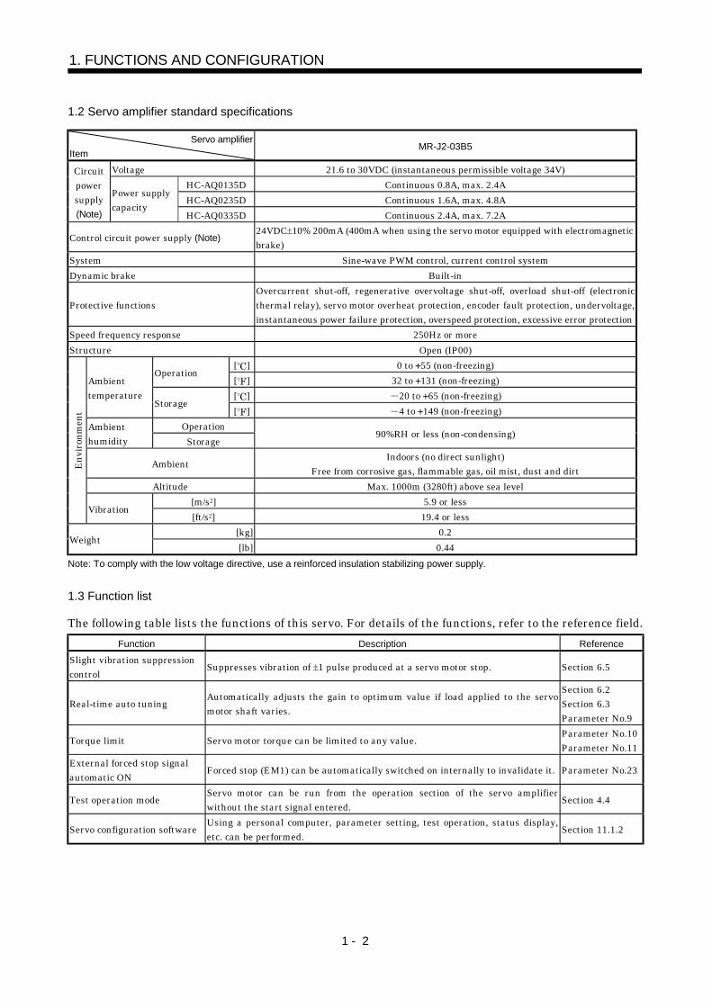
1.2 Servo amplifier standard specifications
Servo amplifierItem
MR-J2-03B5
Voltage 21.6 to 30VDC (instantaneous permissible voltage 34V)HC-AQ0135D Continuous 0.8A, max. 2.4AHC-AQ0235D Continuous 1.6A, max. 4.8A
Circuitpowersupply(Note)
Power supplycapacity
HC-AQ0335D Continuous 2.4A, max. 7.2A
Control circuit power supply (Note)24VDC 10% 200mA (400mA when using the servo motor equipped with electromagneticbrake)
System Sine-wave PWM control, current control systemDynamic brake Built-in
Protective functionsOvercurrent shut-off, regenerative overvoltage shut-off, overload shut-off (electronicthermal relay), servo motor overheat protection, encoder fault protection, undervoltage,instantaneous power failure protection, overspeed protection, excessive error protection
Speed frequency response 250Hz or moreStructure Open (IP00)
[ ] 0 to 55 (non-freezing)Operation
[ ] 32 to 131 (non-freezing)[ ] 20 to 65 (non-freezing)
Ambienttemperature
Storage[ ] 4 to 149 (non-freezing)
OperationAmbienthumidity Storage
90%RH or less (non-condensing)
Ambient Indoors (no direct sunlight)Free from corrosive gas, flammable gas, oil mist, dust and dirt
Altitude Max. 1000m (3280ft) above sea level[m/s2] 5.9 or less
Envi
ronm
ent
Vibration[ft/s2] 19.4 or less
[kg] 0.2Weight
[lb] 0.44Note: To comply with the low voltage directive, use a reinforced insulation stabilizing power supply.
1.3 Function list
The following table lists the functions of this servo. For details of the functions, refer to the reference field.Function Description Reference
Slight vibration suppressioncontrol Suppresses vibration of 1 pulse produced at a servo motor stop. Section 6.5
Real-time auto tuning Automatically adjusts the gain to optimum value if load applied to the servomotor shaft varies.
Section 6.2Section 6.3Parameter No.9
Torque limit Servo motor torque can be limited to any value. Parameter No.10Parameter No.11
External forced stop signalautomatic ON Forced stop (EM1) can be automatically switched on internally to invalidate it. Parameter No.23
Test operation mode Servo motor can be run from the operation section of the servo amplifierwithout the start signal entered. Section 4.4
Servo configuration software Using a personal computer, parameter setting, test operation, status display,etc. can be performed. Section 11.1.2
1 - 3
1. FUNCTIONS AND CONFIGURATION
1.4 Model code definition
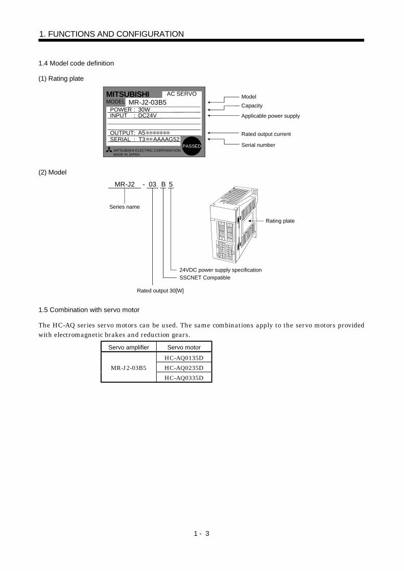
(1) Rating plate
Model Capacity
Applicable power supply
Rated output current
Serial number
A5
MITSUBISHI
MADE IN JAPAN
MODEL MR-J2-03B5
MITSUBISHI ELECTRIC CORPORATION
30W DC24V
POWER : INPUT :
OUTPUT: SERIAL :
AC SERVO
T3 AAAAG52PASSED
(2) Model
MR-J2 - 03 5
Series name
24VDC power supply specificationSSCNET Compatible
Rated output 30[W]
Rating plate
B
1.5 Combination with servo motor
The HC-AQ series servo motors can be used. The same combinations apply to the servo motors providedwith electromagnetic brakes and reduction gears.
Servo amplifier Servo motor
HC-AQ0135DHC-AQ0235DMR-J2-03B5HC-AQ0335D
1 - 4
1. FUNCTIONS AND CONFIGURATION
1.6 Parts identification
Section 4.3
1
CB
987
54
3
0 F
D
1
CB
987
54
3
0 F
D
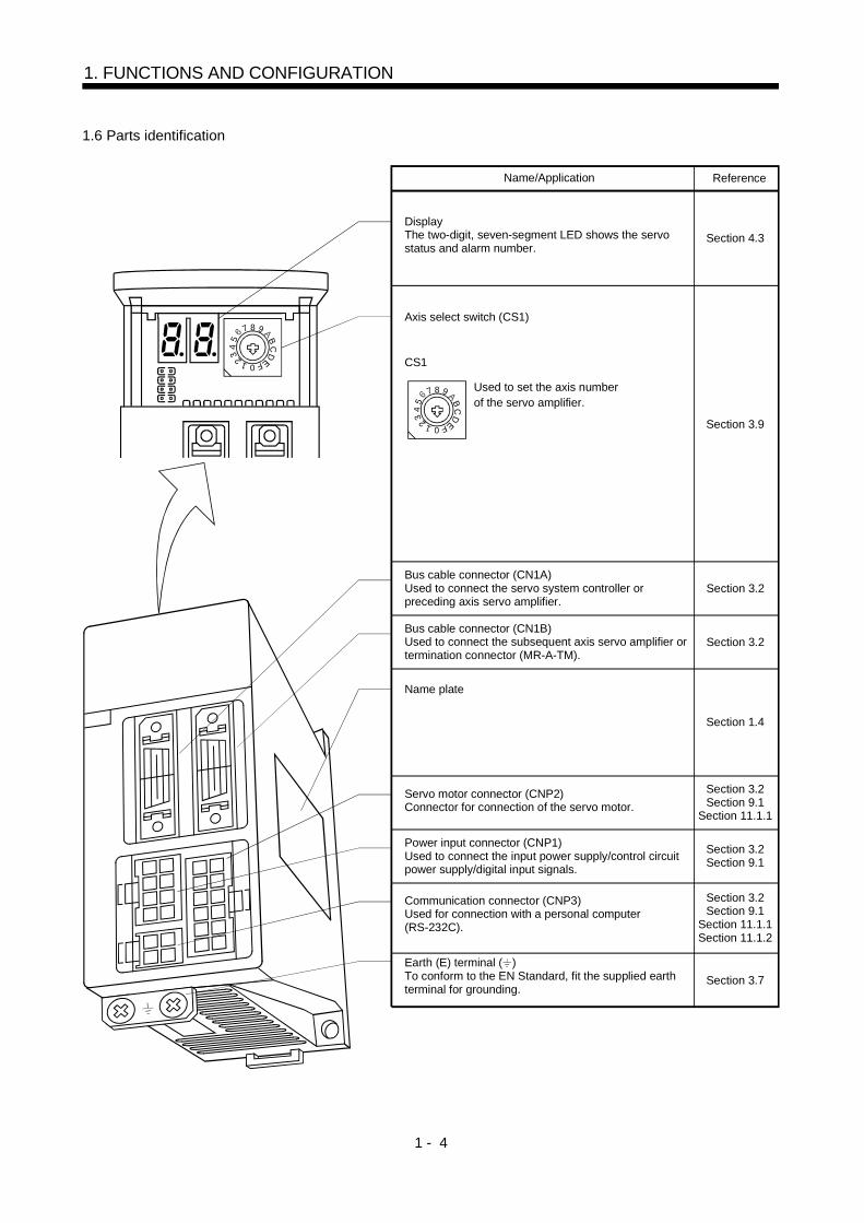
ReferenceName/Application
DisplayThe two-digit, seven-segment LED shows the servo status and alarm number.
Axis select switch (CS1)
CS1
Used to set the axis numberof the servo amplifier.
Section 3.9
Bus cable connector (CN1A)Used to connect the servo system controller orpreceding axis servo amplifier.
Name plate
Servo motor connector (CNP2)Connector for connection of the servo motor.
Power input connector (CNP1) Used to connect the input power supply/control circuitpower supply/digital input signals.
Earth (E) terminal ( )To conform to the EN Standard, fit the supplied earthterminal for grounding.
Section 3.2
Bus cable connector (CN1B)Used to connect the subsequent axis servo amplifier ortermination connector (MR-A-TM).
Section 1.4
Communication connector (CNP3) Used for connection with a personal computer(RS-232C).
Section 3.2
Section 3.2Section 9.1
Section 11.1.1
Section 3.2Section 9.1
Section 3.2Section 9.1
Section 11.1.1Section 11.1.2
Section 3.7
1 - 5
1. FUNCTIONS AND CONFIGURATION
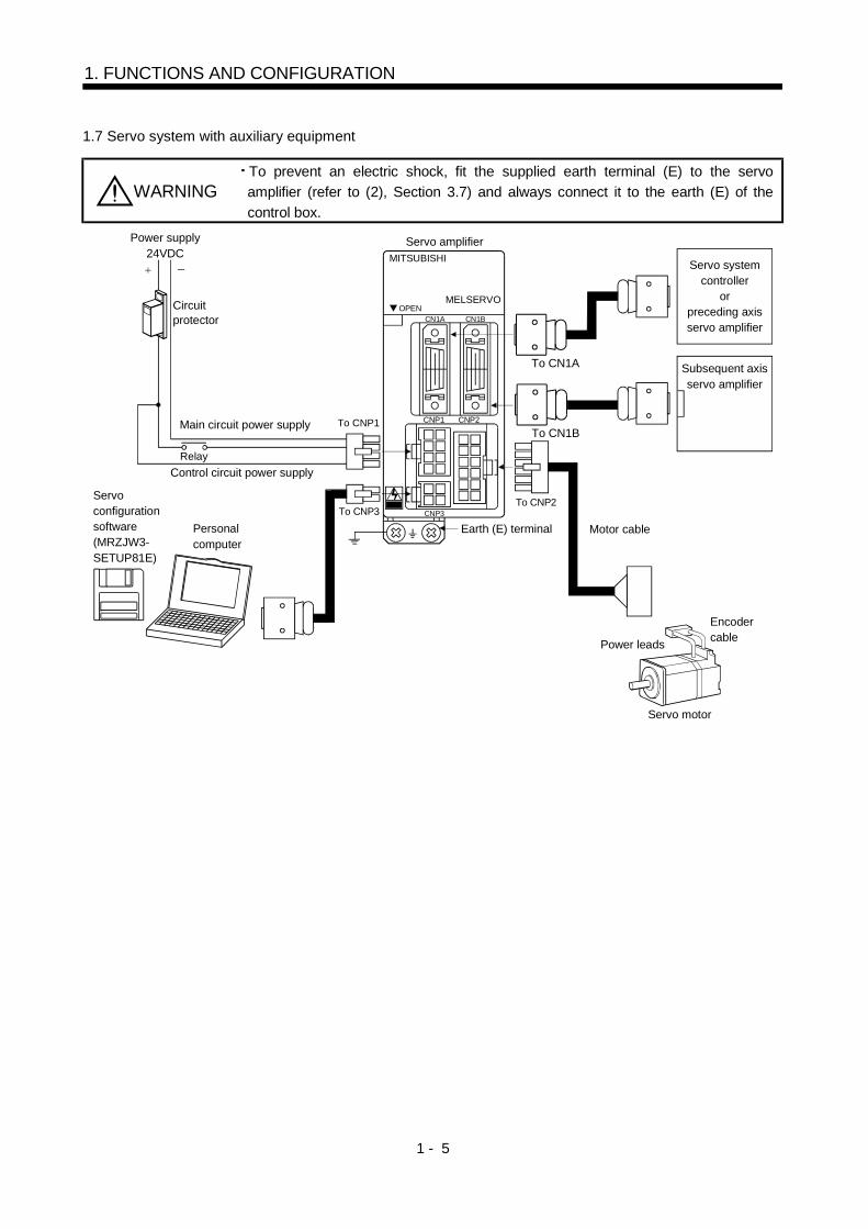
1.7 Servo system with auxiliary equipment
WARNINGTo prevent an electric shock, fit the supplied earth terminal (E) to the servoamplifier (refer to (2), Section 3.7) and always connect it to the earth (E) of thecontrol box.
Circuitprotector
MITSUBISHI
OPENCN1A CN1B
CNP1 CNP2
CNP3
MELSERVO
To CNP2 To CNP3
Servo amplifier
Personalcomputer
Power leads
Encodercable
Servo motor
Power supply24VDC
Main circuit power supply
RelayControl circuit power supply
To CNP1
Earth (E) terminal Motor cable
To CN1B
To CN1A
Servo systemcontroller
orpreceding axisservo amplifier
Subsequent axisservo amplifier
Servo configurationsoftware(MRZJW3-SETUP81E)

1 - 6
1. FUNCTIONS AND CONFIGURATION
MEMO
2 - 1
2. INSTALLATION
2. INSTALLATION
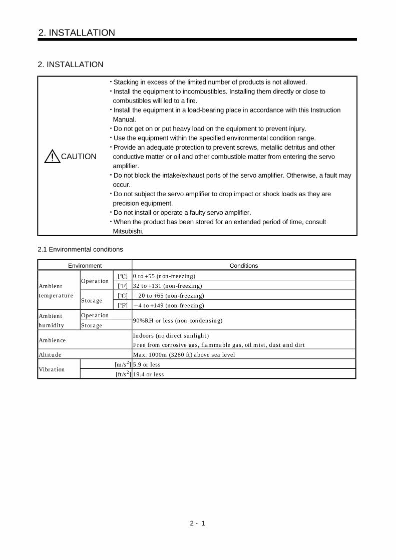
CAUTION
Stacking in excess of the limited number of products is not allowed.Install the equipment to incombustibles. Installing them directly or close tocombustibles will led to a fire.Install the equipment in a load-bearing place in accordance with this InstructionManual.Do not get on or put heavy load on the equipment to prevent injury.Use the equipment within the specified environmental condition range.Provide an adequate protection to prevent screws, metallic detritus and otherconductive matter or oil and other combustible matter from entering the servoamplifier.Do not block the intake/exhaust ports of the servo amplifier. Otherwise, a fault mayoccur.Do not subject the servo amplifier to drop impact or shock loads as they areprecision equipment.Do not install or operate a faulty servo amplifier.When the product has been stored for an extended period of time, consultMitsubishi.
2.1 Environmental conditions
Environment Conditions
[ ] 0 to 55 (non-freezing)Operation
[ ] 32 to 131 (non-freezing)[ ] 20 to 65 (non-freezing)
Ambienttemperature
Storage[ ] 4 to 149 (non-freezing)
OperationAmbienthumidity Storage
90%RH or less (non-condensing)
AmbienceIndoors (no direct sunlight)Free from corrosive gas, flammable gas, oil mist, dust and dirt
Altitude Max. 1000m (3280 ft) above sea level[m/s2] 5.9 or less
Vibration[ft/s2] 19.4 or less
2 - 2
2. INSTALLATION
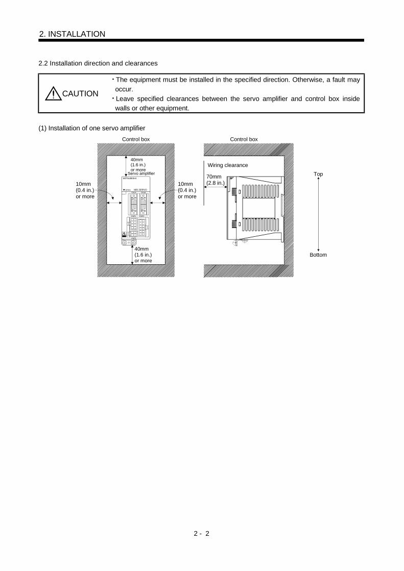
2.2 Installation direction and clearances
CAUTION
The equipment must be installed in the specified direction. Otherwise, a fault mayoccur.Leave specified clearances between the servo amplifier and control box insidewalls or other equipment.
(1) Installation of one servo amplifier
70mm(2.8 in.)
MITSUBISHI
OPENCN1A CN1B
CNP1 CNP2
CNP3
MELSERVO
10mm(0.4 in.)or more
40mm(1.6 in.)or more
10mm(0.4 in.)or more
40mm(1.6 in.)or more
Top
Bottom
Wiring clearance
Control box Control box
Servo amplifier
2 - 3
2. INSTALLATION
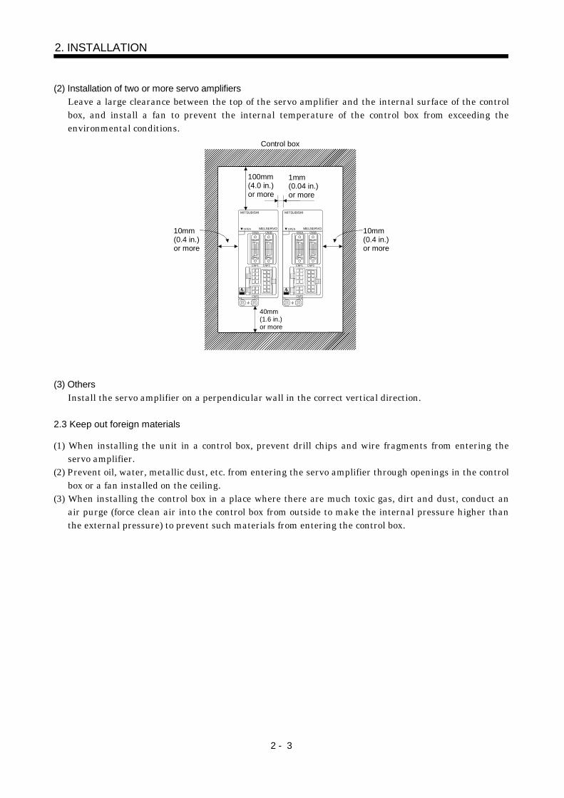
(2) Installation of two or more servo amplifiersLeave a large clearance between the top of the servo amplifier and the internal surface of the controlbox, and install a fan to prevent the internal temperature of the control box from exceeding theenvironmental conditions.
Control box
100mm(4.0 in.)or more
10mm(0.4 in.)or more
1mm(0.04 in.)or more
MITSUBISHI
OPENCN1A CN1B
CNP1 CNP2
CNP3
MELSERVO
MITSUBISHI
OPENCN1A CN1B
CNP1 CNP2
CNP3
MELSERVO10mm(0.4 in.)or more
40mm(1.6 in.)or more
(3) OthersInstall the servo amplifier on a perpendicular wall in the correct vertical direction.
2.3 Keep out foreign materials
(1) When installing the unit in a control box, prevent drill chips and wire fragments from entering theservo amplifier.
(2) Prevent oil, water, metallic dust, etc. from entering the servo amplifier through openings in the controlbox or a fan installed on the ceiling.
(3) When installing the control box in a place where there are much toxic gas, dirt and dust, conduct anair purge (force clean air into the control box from outside to make the internal pressure higher thanthe external pressure) to prevent such materials from entering the control box.
2 - 4
2. INSTALLATION
2.4 Cable stress
(1) The way of clamping the cable must be fully examined so that flexing stress and cable's own weightstress are not applied to the cable connection.
(2) For use in any application where the servo motor moves, fix the cables (encoder, power supply, brake)supplied with the servo motor, and flex the optional motor cable or the power supply and brake wiringcables. Use the optional motor cable within the flexing life flexing life range. Use the power supply andbrake wiring cables within the flexing life of the cables.
(3) Avoid any probability that the cable sheath might be cut by sharp chips, rubbed by a machine corneror stamped by workers or vehicles.
(4) For installation on a machine where the servo motor will move, the flexing radius should be made aslarge as possible. Refer to section 10.3 for the flexing life.
2 - 5
2. INSTALLATION
2.5 Using the DIN rail for installation
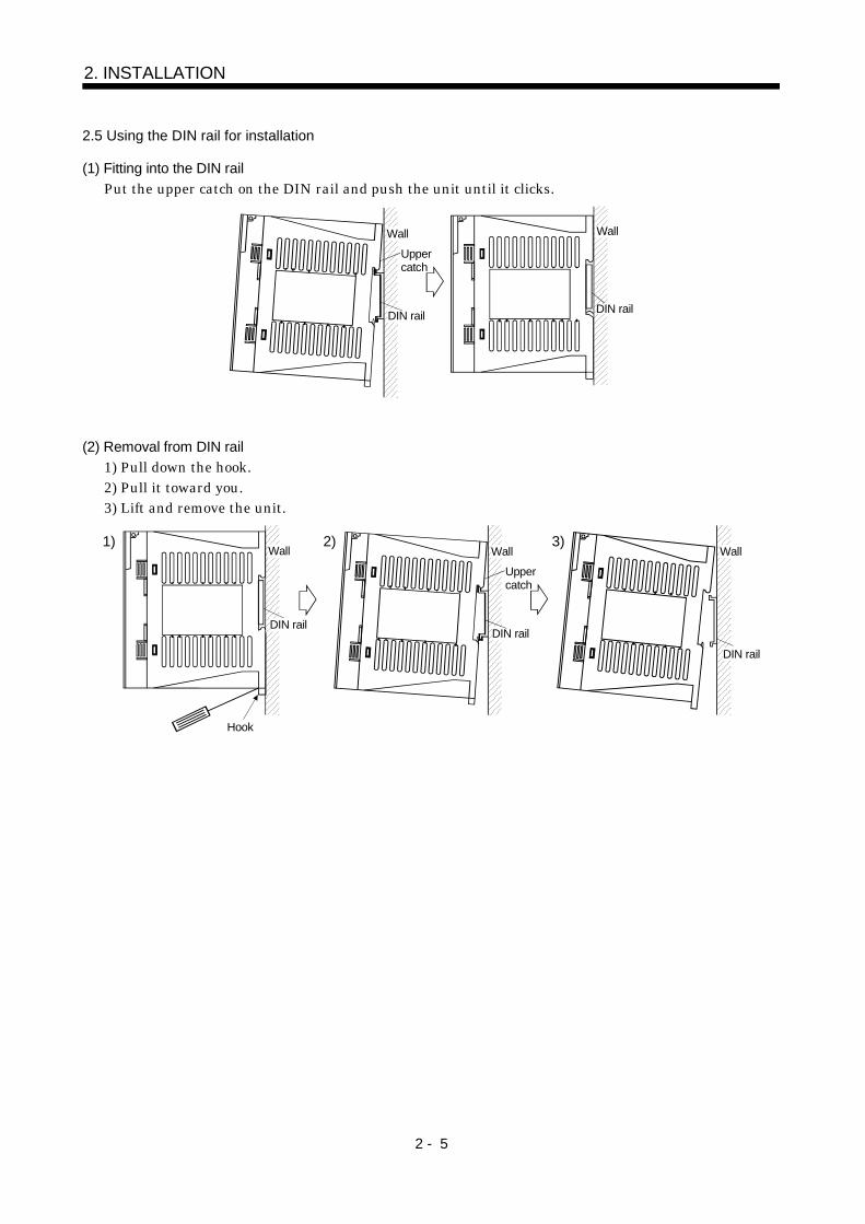
(1) Fitting into the DIN railPut the upper catch on the DIN rail and push the unit until it clicks.
Wall
DIN rail
Uppercatch
Wall
DIN rail
(2) Removal from DIN rail1) Pull down the hook.2) Pull it toward you.3) Lift and remove the unit.
Wall
Hook
1)
DIN rail
Uppercatch
Wall
DIN rail
2) 3)
DIN rail
Wall

2 - 6
2. INSTALLATION
MEMO
3 - 1
3. SIGNALS AND WIRING
3. SIGNALS AND WIRING
WARNING
Any person who is involved in wiring should be fully competent to do the work.Before starting wiring, make sure that the voltage is safe in the tester more than 10minutes after power-off. Otherwise, you may get an electric shock.Ground the servo amplifier and the servo motor securely.Do not attempt to wire the servo amplifier and servo motor until they have beeninstalled. Otherwise, you may get an electric shock.The cables should not be damaged, stressed excessively, loaded heavily, orpinched. Otherwise, you may get an electric shock.
CAUTION
Wire the equipment correctly and securely. Otherwise, the servo motor maymisoperate, resulting in injury.Connect cables to correct terminals to prevent a burst, fault, etc.Ensure that polarity ( , ) is correct. Otherwise, a burst, damage, etc. may occur.Use a noise filter, etc. to minimize the influence of electromagnetic interference,which may be given to electronic equipment used near the servo amplifier.Do not install a power capacitor, surge suppressor or radio noise filter with thepower line of the servo motor.Do not modify the equipment.
POINTCN1A and CN1B have the same shape. Wrong connection of the connectorswill lead to a failure. Connect them correctly.
3 - 2
3. SIGNALS AND WIRING
3.1 Connection example of control signal system
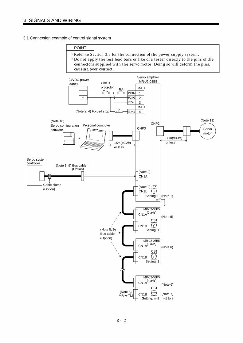
POINTRefer to Section 3.5 for the connection of the power supply system.Do not apply the test lead bars or like of a tester directly to the pins of theconnectors supplied with the servo motor. Doing so will deform the pins,causing poor contact.
Servo amplifierMR-J2-03B5
(Note 3)CN1A
CN1BCS1
Setting: 0
CN1A
CN1B
CN1A
CN1B
CN1A
CN1B
CS1
CS1
CS1
n 1 to 8
(Note 6)
(Note 7)(Note 8)MR-A-TM
Servo systemcontroller
RA
24VDC powersupply
123
4EM1
(Note 1)
Circuitprotector CNP1
P24M P24G P24L
CNP1 (Note 2, 4) Forced stop
(Note 10)Servo configurationsoftware
Personal computer
(Note 5, 9) Bus cable(Option)
Cable clamp(Option)
15m(49.2ft)or less
CNP3 CNP2
(Note 3)
MR-J2-03B5(2 axis)
Setting: 1
(Note 6)
MR-J2-03B5(3 axis)
(Note 6)
Setting: 2
MR-J2-03B5(n axis)
Setting: n 1
(Note 5, 9)Bus cable(Option)
30m(98.4ft)or less
(Note 11)
Servomotor
3 - 3
3. SIGNALS AND WIRING
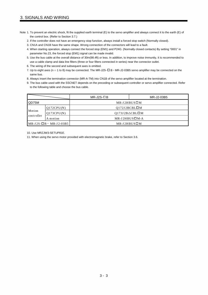
Note 1. To prevent an electric shock, fit the supplied earth terminal (E) to the servo amplifier and always connect it to the earth (E) ofthe control box. (Refer to Section 3.7.)
2. If the controller does not have an emergency stop function, always install a forced stop switch (Normally closed).3. CN1A and CN1B have the same shape. Wrong connection of the connectors will lead to a fault.4. When starting operation, always connect the forced stop (EM1) and P24G. (Normally closed contacts) By setting “0001” in
parameter No.23, the forced stop (EM1) signal can be made invalid.5. Use the bus cable at the overall distance of 30m(98.4ft) or less. In addition, to improve noise immunity, it is recommended to
use a cable clamp and data line filters (three or four filters connected in series) near the connector outlet.6. The wiring of the second and subsequent axes is omitted.7. Up to eight axes (n 1 to 8) may be connected. The MR-J2S- B MR-J2-03B5 servo amplifier may be connected on the
same bus.8. Always insert the termination connector (MR-A-TM) into CN1B of the servo amplifier located at the termination.9. The bus cable used with the SSCNET depends on the preceding or subsequent controller or servo amplifier connected. Refer
to the following table and choose the bus cable.
MR-J2S- B MR-J2-03B5
QD75M MR-J2HBUS MQ172CPU(N) Q172J2BCBL MQ173CPU(N) Q173J2B CBL M
Motioncontroller
A motion MR-J2HBUS M-AMR-J2S- B MR-J2-03B5 MR-J2HBUS M
10. Use MRZJW3-SETUP81E.11. When using the servo motor provided with electromagnetic brake, refer to Section 3.6.
3 - 4
3. SIGNALS AND WIRING
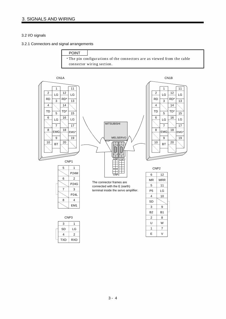
3.2 I/O signals
3.2.1 Connectors and signal arrangements
POINTThe pin configurations of the connectors are as viewed from the cableconnector wiring section.
12
3
5
4
6
7
9
8
10
1112
1314
1516
1718
1920
12
3
5
4
6
7
9
8
10
1112
1314
1516
1718
1920
MITSUBISHI
MELSERVO
CN1A CN1B
5 1
P24M
6 2
P24G
7 3
P24L
8 4
EM1
CNP1
B2 B1
5
1
MR MRR
6
2
P5 LG
11
12
SD
104
7
3
U W
8
9
E V
CNP2
1
SD
2
TXD
LG
3
RXD
4
CNP3
CNP1
CNP3
CNP2
RD
TD
LG
EMG
LG
BT
RD*
TD*
LG
LG
EMG*
RD
TD
LG
EMG
LG
BT
RD*
TD*
LG
LG
EMG*
The connector frames areconnected with the E (earth)terminal inside the servo amplifier.
3 - 5
3. SIGNALS AND WIRING
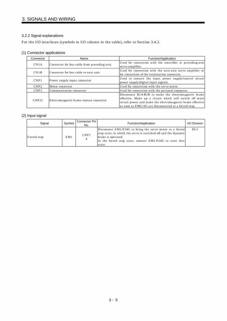
3.2.2 Signal explanationsFor the I/O interfaces (symbols in I/O column in the table), refer to Section 3.4.2.
(1) Connector applicationsConnector Name Function/Application
CN1A Connector for bus cable from preceding axis. Used for connection with the controller or preceding-axisservo amplifier.
CN1B Connector for bus cable to next axis Used for connection with the next-axis servo amplifier orfor connection of the termination connector.
CNP1 Power supply input connector Used to connect the input power supply/control circuitpower supply/digital input signals.
CNP2 Motor connector Used for connection with the servo motor.CNP3 Communication connector Used for connection with the personal computer.
CNP21 Electromagnetic brake contact connectorDisconnect B1A-B1B to make the electromagnetic brakeeffective. Make up a circuit which will switch off maincircuit power and make the electromagnetic brake effectiveas soon as EMG-SG are disconnected at a forced stop.
(2) Input signal
Signal Symbol Connector PinNo. Function/Application I/O Division
Forced stop EM1 CNP14
Disconnect EM1-P24G to bring the servo motor to a forcedstop state, in which the servo is switched off and the dynamicbrake is operated.In the forced stop state, connect EM1-P24G to reset thatstate.
DI-1
3 - 6
3. SIGNALS AND WIRING
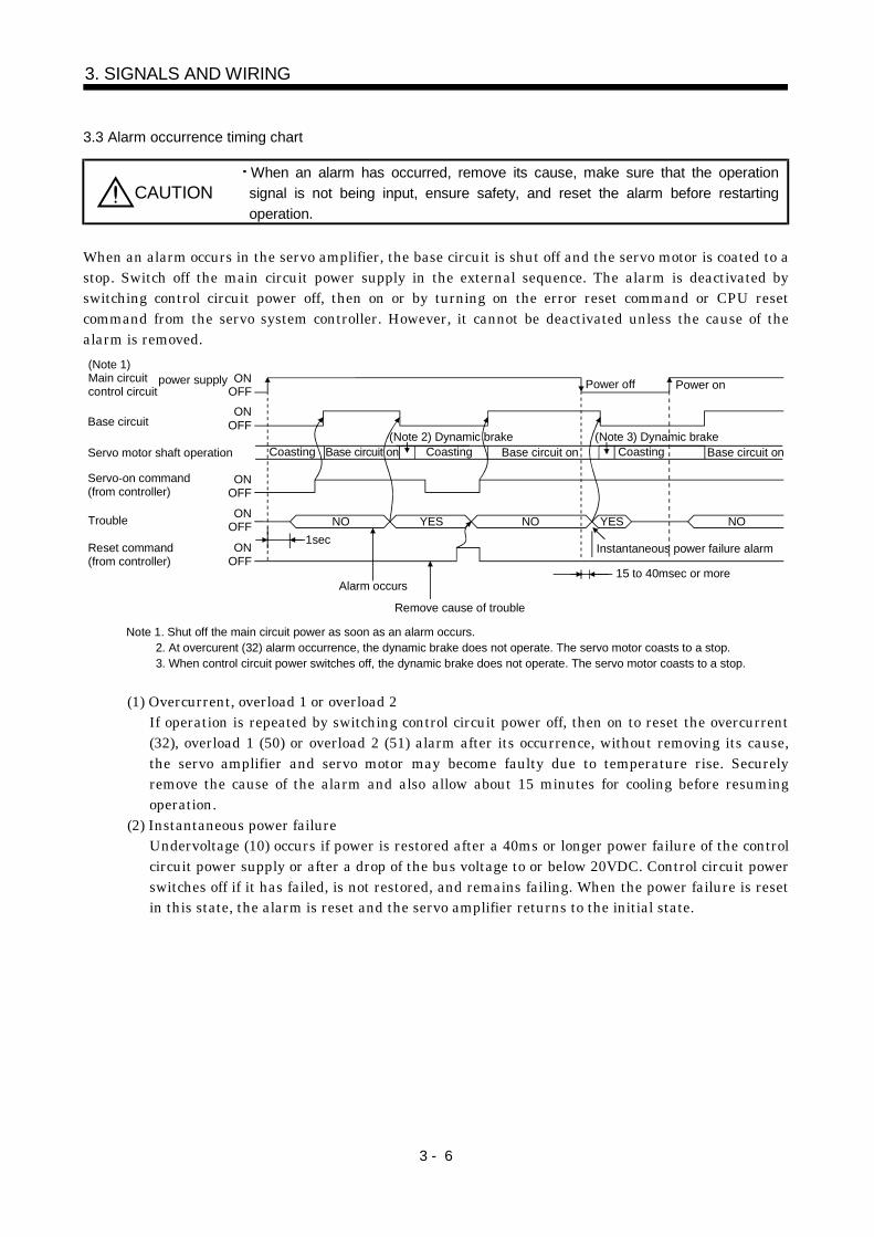
3.3 Alarm occurrence timing chart
CAUTIONWhen an alarm has occurred, remove its cause, make sure that the operationsignal is not being input, ensure safety, and reset the alarm before restartingoperation.
When an alarm occurs in the servo amplifier, the base circuit is shut off and the servo motor is coated to astop. Switch off the main circuit power supply in the external sequence. The alarm is deactivated byswitching control circuit power off, then on or by turning on the error reset command or CPU resetcommand from the servo system controller. However, it cannot be deactivated unless the cause of thealarm is removed.
Note 1. Shut off the main circuit power as soon as an alarm occurs. 2. At overcurent (32) alarm occurrence, the dynamic brake does not operate. The servo motor coasts to a stop. 3. When control circuit power switches off, the dynamic brake does not operate. The servo motor coasts to a stop.
ONOFFON
OFFBase circuit
ONOFF
Servo-on command(from controller)
ONOFF
Reset command(from controller)
ONOFFTrouble
1sec
Alarm occurs
Remove cause of trouble
Power off Power on
Instantaneous power failure alarm
15 to 40msec or more
Servo motor shaft operation Base circuit on Base circuit on Base circuit onCoasting Coasting Coasting
(Note 1)Main circuitcontrol circuit
NOYESNO YES NO
(Note 3) Dynamic brake(Note 2) Dynamic brake
power supply
(1) Overcurrent, overload 1 or overload 2If operation is repeated by switching control circuit power off, then on to reset the overcurrent(32), overload 1 (50) or overload 2 (51) alarm after its occurrence, without removing its cause,the servo amplifier and servo motor may become faulty due to temperature rise. Securelyremove the cause of the alarm and also allow about 15 minutes for cooling before resumingoperation.
(2) Instantaneous power failureUndervoltage (10) occurs if power is restored after a 40ms or longer power failure of the controlcircuit power supply or after a drop of the bus voltage to or below 20VDC. Control circuit powerswitches off if it has failed, is not restored, and remains failing. When the power failure is resetin this state, the alarm is reset and the servo amplifier returns to the initial state.
3 - 7
3. SIGNALS AND WIRING
3.4 Interfaces
3.4.1 Common line
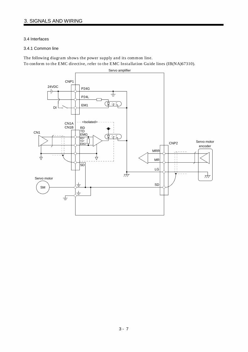
The following diagram shows the power supply and its common line.To conform to the EMC directive, refer to the EMC Installation Guide lines (IB(NA)67310).
CNP1
P24G
P24L
EM1DI
CN1ACN1B
SD
MRR
MR
LG
SD
CNP2
CN1
Servo amplifier
24VDC
<Isolated>
RDTDEMG RD*TD*EMG*
Servo motor
SM
Servo motorencoder
3 - 8
3. SIGNALS AND WIRING
3.4.2 Detailed description of the interfaces
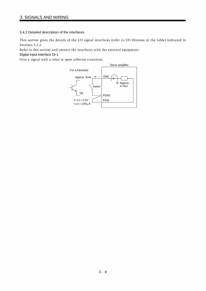
This section gives the details of the I/O signal interfaces (refer to I/O Division in the table) indicated inSections 3.2.2.Refer to this section and connect the interfaces with the external equipment.Digital input interface DI-1Give a signal with a relay or open collector transistor.
R: Approx.
EM1
Switch
TR
P24L
P24G
For a transistor
Approx. 5mA
V CES 1.0VI CEO 100 A
4.7k
Servo amplifier
3 - 9
3. SIGNALS AND WIRING
3.5 Input power supply circuit
CAUTION
When the servo amplifier has become faulty, switch power off on the servoamplifier power side. Continuous flow of a large current may cause a fire.Switch power off at detection of an alarm. Otherwise, a regenerative braketransistor fault or the like may overheat the regenerative brake resistor, causing afire.
POINTIf the equipment does not comply with the EN Standard, use the insulated24VDC power supply.
3.5.1 Connection example
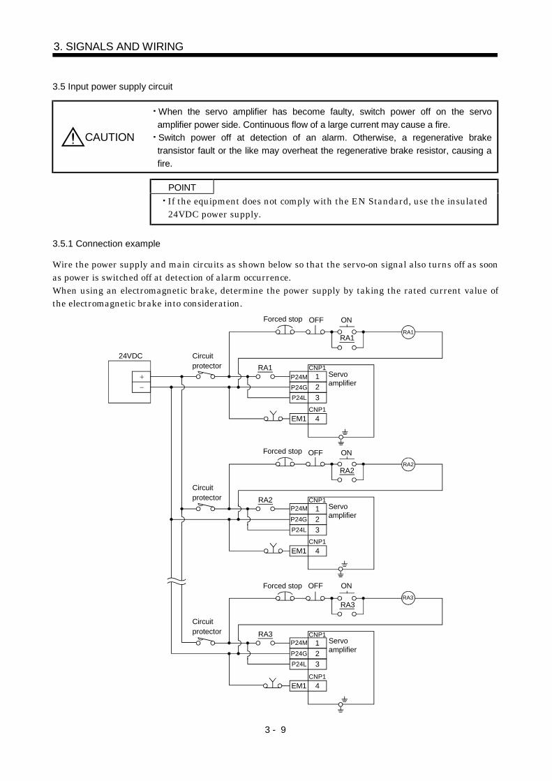
Wire the power supply and main circuits as shown below so that the servo-on signal also turns off as soonas power is switched off at detection of alarm occurrence.When using an electromagnetic brake, determine the power supply by taking the rated current value ofthe electromagnetic brake into consideration.
123
4
OFF ON
RA1
EM1
CNP1
CNP1
123
4
RA2
OFF ON
RA2
EM1
CNP1
CNP1
123
4
RA3
OFF ON
RA3
EM1
CNP1
CNP1
RA1
24VDC
Forced stop
Circuitprotector
P24M P24G P24L
Servoamplifier
RA1
Forced stopRA2
Circuitprotector
P24L
P24MP24G
Servoamplifier
Forced stopRA3
Servoamplifier
P24L
P24MP24G
Circuitprotector
3 - 10
3. SIGNALS AND WIRING
3.5.2 Explanation of signals
Abbreviation Signal Name DescriptionP24M Main circuit power input Power supply for main circuit.
P24G Power ground Main circuit power supply and control circuit power supply ground. Connectedto SG and LG inside the unit.
P24L Control circuit power input Control circuit power supply and digital I/O power supply. Always use astabilizing power supply.
Ground Connect to the earth of the control box for grounding.
3.5.3 Power-on sequence
(1) Power-on procedure1) Always wire the power supply as shown in above Section 3.5.1 using the relay with the main circuit
power supply. Configure up an external sequence to switch off the relay as soon as an alarm occurs.2) Switch on the control circuit power supply L11, L21 simultaneously with the main circuit power
supply or before switching on the main circuit power supply. If the main circuit power supply is noton, the display shows the corresponding warning. However, by switching on the main circuit powersupply, the warning disappears and the servo amplifier will operate properly.
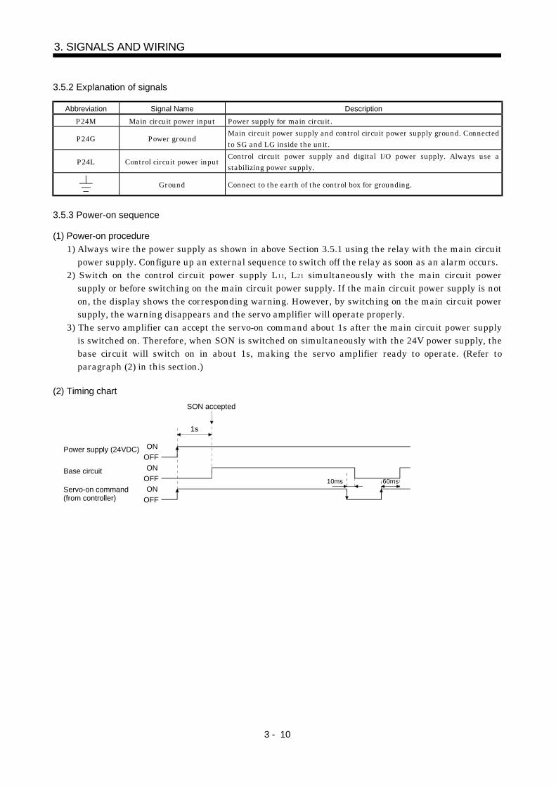
3) The servo amplifier can accept the servo-on command about 1s after the main circuit power supplyis switched on. Therefore, when SON is switched on simultaneously with the 24V power supply, thebase circuit will switch on in about 1s, making the servo amplifier ready to operate. (Refer toparagraph (2) in this section.)
(2) Timing chart
ONOFFON
OFF
Power supply (24VDC)
Base circuit
ONOFF
Servo-on command(from controller)
10ms 60ms
1s
SON accepted
3 - 11
3. SIGNALS AND WIRING
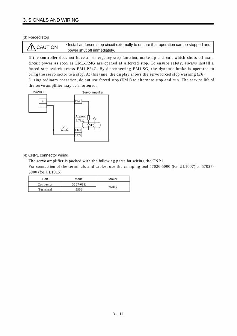
(3) Forced stop
CAUTION Install an forced stop circuit externally to ensure that operation can be stopped andpower shut off immediately.
If the controller does not have an emergency stop function, make up a circuit which shuts off maincircuit power as soon as EM1-P24G are opened at a forced stop. To ensure safety, always install aforced stop switch across EM1-P24G. By disconnecting EM1-SG, the dynamic brake is operated tobring the servo motor to a stop. At this time, the display shows the servo forced stop warning (E6).During ordinary operation, do not use forced stop (EM1) to alternate stop and run. The service life ofthe servo amplifier may be shortened.
24VDC
P24L
Servo amplifier
Approx.4.7k
EM1 P24G
(4) CNP1 connector wiringThe servo amplifier is packed with the following parts for wiring the CNP1.For connection of the terminals and cables, use the crimping tool 57026-5000 (for UL1007) or 57027-5000 (for UL1015).
Part Model MakerConnector 5557-08RTerminal 5556
molex
3 - 12
3. SIGNALS AND WIRING
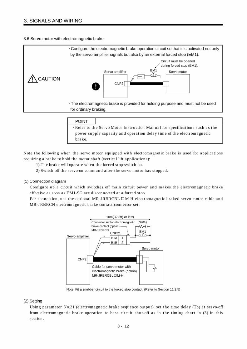
3.6 Servo motor with electromagnetic brake
CAUTION
Configure the electromagnetic brake operation circuit so that it is activated not onlyby the servo amplifier signals but also by an external forced stop (EM1).
CNP2
EM1 Servo amplifier
Circuit must be openedduring forced stop (EM1).
Servo motor
The electromagnetic brake is provided for holding purpose and must not be usedfor ordinary braking.
POINTRefer to the Servo Motor Instruction Manual for specifications such as thepower supply capacity and operation delay time of the electromagneticbrake.
Note the following when the servo motor equipped with electromagnetic brake is used for applicationsrequiring a brake to hold the motor shaft (vertical lift applications):
1) The brake will operate when the forced stop switch on.2) Switch off the servo-on command after the servo motor has stopped.
(1) Connection diagramConfigure up a circuit which switches off main circuit power and makes the electromagnetic brakeeffective as soon as EM1-SG are disconnected at a forced stop.For connection, use the optional MR-JRBRCBL M-H electromagnetic braked servo motor cable andMR-JRBRCN electromagnetic brake contact connector set.
B1A 1B1B 2
EM1
10m(32.8ft) or less
Servo amplifier
Connector set for electromagneticbrake contact (option)MR-JRBRCN
(Note)
CNP2
Servo motor
Cable for servo motor withelectromagnetic brake (option)MR-JRBRCBL M-H
Note. Fit a snubber circuit to the forced stop contact. (Refer to Section 11.2.5)
CNP21
(2) SettingUsing parameter No.21 (electromagnetic brake sequence output), set the time delay (Tb) at servo-offfrom electromagnetic brake operation to base circuit shut-off as in the timing chart in (3) in thissection.
3 - 13
3. SIGNALS AND WIRING
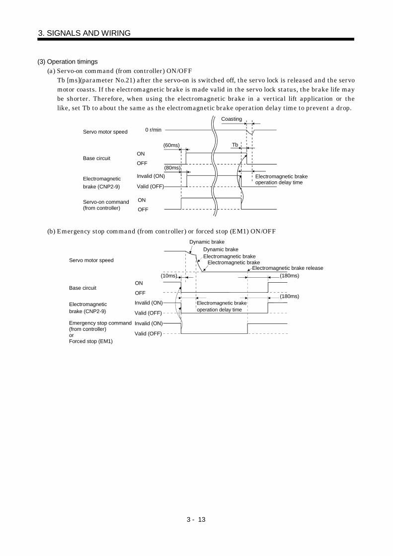
(3) Operation timings(a) Servo-on command (from controller) ON/OFF
Tb [ms](parameter No.21) after the servo-on is switched off, the servo lock is released and the servomotor coasts. If the electromagnetic brake is made valid in the servo lock status, the brake life maybe shorter. Therefore, when using the electromagnetic brake in a vertical lift application or thelike, set Tb to about the same as the electromagnetic brake operation delay time to prevent a drop.
Servo motor speed
Electromagnetic brake (CNP2-9)
ON
OFFBase circuit
Invalid (ON)
Valid (OFF)
ON
OFFServo-on command(from controller)
Electromagnetic brake operation delay time
Tb
Coasting
0 r/min
(60ms)
(80ms)
(b) Emergency stop command (from controller) or forced stop (EM1) ON/OFF
Servo motor speed
Electromagneticbrake (CNP2-9)
ON
OFFBase circuit
Invalid (ON)
Valid (OFF)
Emergency stop command(from controller)orForced stop (EM1)
(10ms) (180ms)
(180ms)
Dynamic brakeDynamic brakeElectromagnetic brake
Electromagnetic brake
Invalid (ON)
Valid (OFF)
Electromagnetic brakeoperation delay time
Electromagnetic brake release
3 - 14
3. SIGNALS AND WIRING
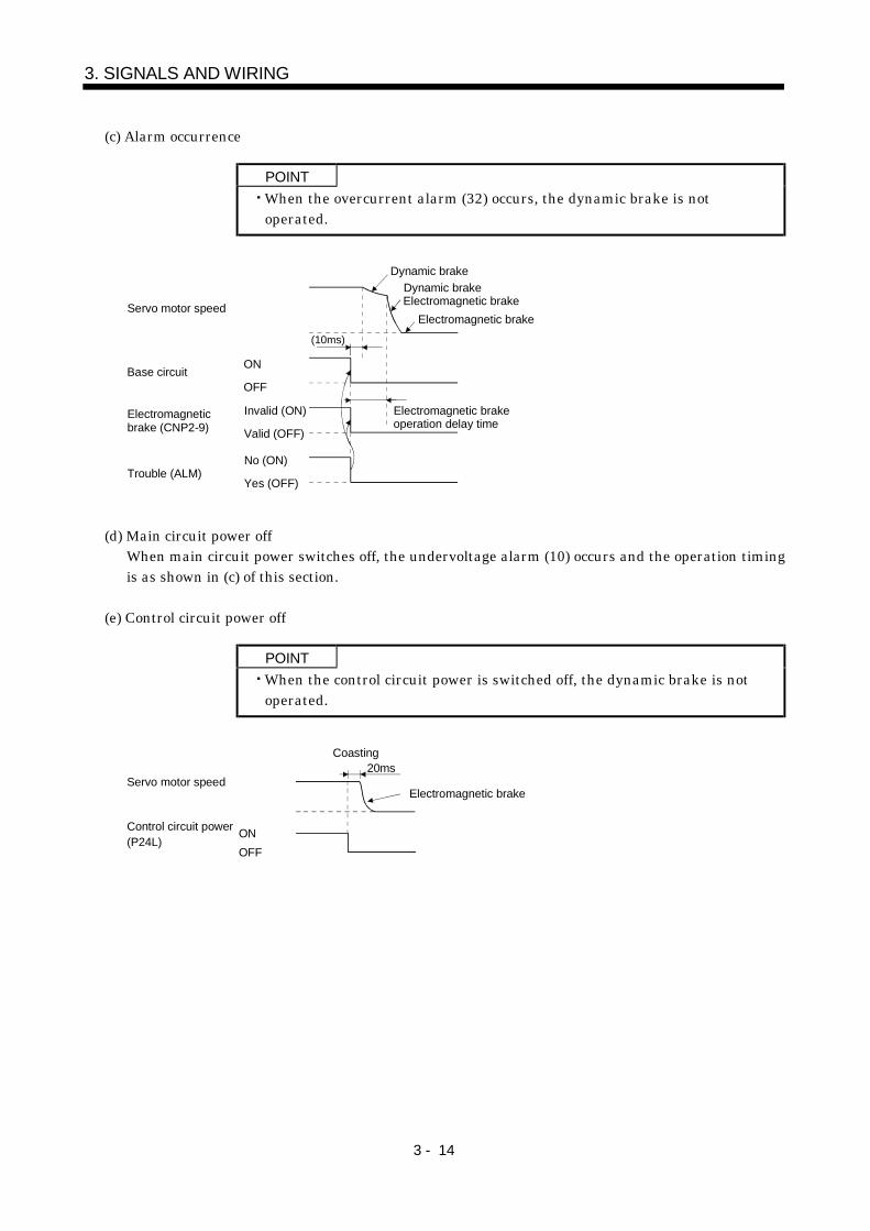
(c) Alarm occurrence
POINTWhen the overcurrent alarm (32) occurs, the dynamic brake is notoperated.
Servo motor speed
ON
OFFBase circuit
Electromagneticbrake (CNP2-9)
Invalid (ON)
Valid (OFF)
Trouble (ALM)No (ON)
Yes (OFF)
Dynamic brakeDynamic brake Electromagnetic brake
Electromagnetic brake operation delay time
Electromagnetic brake
(10ms)
(d) Main circuit power offWhen main circuit power switches off, the undervoltage alarm (10) occurs and the operation timingis as shown in (c) of this section.
(e) Control circuit power off
POINTWhen the control circuit power is switched off, the dynamic brake is notoperated.
20ms
ONOFF
Electromagnetic brakeServo motor speed
Control circuit power(P24L)
Coasting
3 - 15
3. SIGNALS AND WIRING
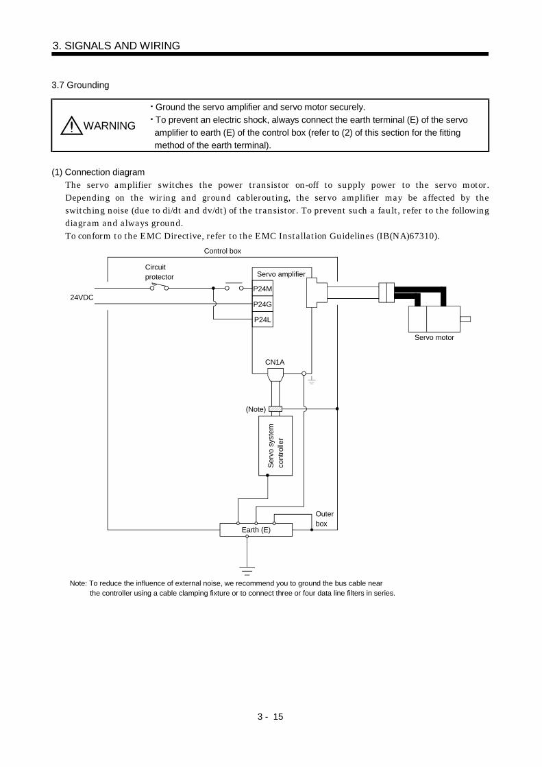
3.7 Grounding
WARNING
Ground the servo amplifier and servo motor securely.To prevent an electric shock, always connect the earth terminal (E) of the servoamplifier to earth (E) of the control box (refer to (2) of this section for the fittingmethod of the earth terminal).
(1) Connection diagramThe servo amplifier switches the power transistor on-off to supply power to the servo motor.Depending on the wiring and ground cablerouting, the servo amplifier may be affected by theswitching noise (due to di/dt and dv/dt) of the transistor. To prevent such a fault, refer to the followingdiagram and always ground.To conform to the EMC Directive, refer to the EMC Installation Guidelines (IB(NA)67310).
Note: To reduce the influence of external noise, we recommend you to ground the bus cable near the controller using a cable clamping fixture or to connect three or four data line filters in series.
P24M
P24G
P24L
24VDC
Circuitprotector
Control box
Servo amplifier
CN1A
(Note)
Serv
o sy
stem
cont
rolle
r
Earth (E)
Outerbox
Servo motor
3 - 16
3. SIGNALS AND WIRING
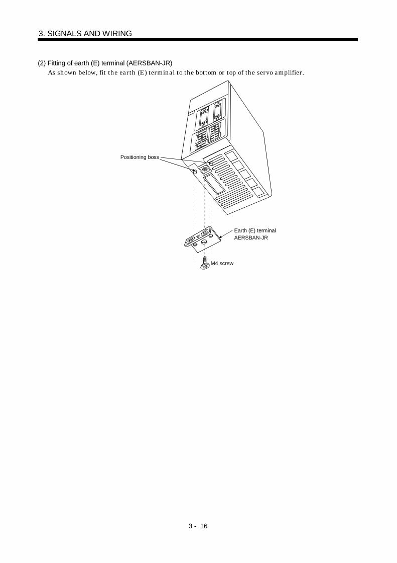
(2) Fitting of earth (E) terminal (AERSBAN-JR)As shown below, fit the earth (E) terminal to the bottom or top of the servo amplifier.
Positioning boss
Earth (E) terminalAERSBAN-JR
M4 screw
3 - 17
3. SIGNALS AND WIRING
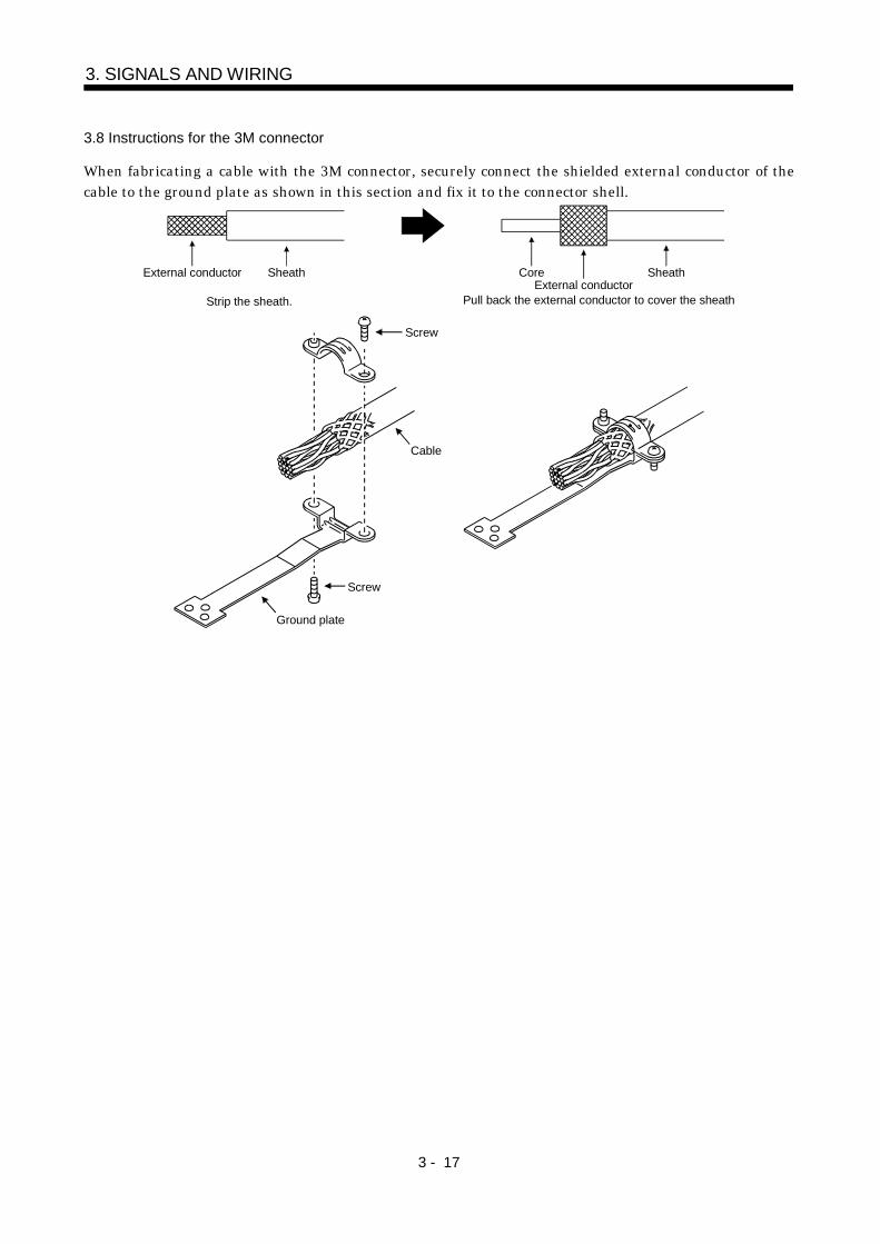
3.8 Instructions for the 3M connector
When fabricating a cable with the 3M connector, securely connect the shielded external conductor of thecable to the ground plate as shown in this section and fix it to the connector shell.
External conductor SheathExternal conductor
Pull back the external conductor to cover the sheath
SheathCore
Strip the sheath.
Screw
Screw
Ground plate
Cable
3 - 18
3. SIGNALS AND WIRING
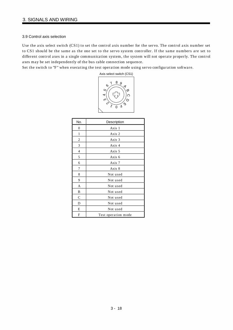
3.9 Control axis selection
Use the axis select switch (CS1) to set the control axis number for the servo. The control axis number setto CS1 should be the same as the one set to the servo system controller. If the same numbers are set todifferent control axes in a single communication system, the system will not operate properly. The controlaxes may be set independently of the bus cable connection sequence.Set the switch to "F" when executing the test operation mode using servo configuration software.
Axis select switch (CS1)
1
CB
A9876
54
32
0 F ED
No. Description
0 Axis 11 Axis 22 Axis 33 Axis 44 Axis 55 Axis 66 Axis 77 Axis 88 Not used9 Not usedA Not usedB Not usedC Not usedD Not usedE Not usedF Test operation mode
4 - 1
4. OPERATION AND DISPLAY
4. OPERATION AND DISPLAY
4.1 When switching power on for the first time
Before starting operation, check the following:
(1) Wiring(a) A correct power supply is connected to the power input terminals (P24M, P24G, P24L) of the servo
amplifier.(b) The servo motor power supply terminals (U, V, W) of the servo amplifier match in phase with the
power input terminals (U, V, W) of the servo motor.(c) The servo motor power supply terminals (U, V, W) of the servo amplifier are not shorted to the
power input terminals (P24M, P24G, P24L) of the servo motor.(d) The servo amplifier is grounded securely.(e) 24VDC or higher voltages are not applied to the pins of connectors CN1A and CN1B.(f) SD and LG of connectors CN1A and CN1B are not shorted.(g) The wiring cables are free from excessive force.(h) CN1A should be connected with the bus cable connected to the servo system controller or preceding
axis servo amplifier, and CN1B should connected with the bus cable connected to the subsequentaxis servo amplifier or with the termination connector (MR-A-TM.)
(2) Axis numberThe axis number setting of CS1 should be the same as that of the servo system controller. (Refer toSection 3.9.)
(3) ParametersOn the servo system controller screen or using the servo configuration software, make sure thatcorrect values have been set in the parameters.
(4) EnvironmentSignal cables and power cables are not shorted by wire offcuts, metallic dust or the like.
(5) Machine(a) The screws in the servo motor installation part and shaft-to-machine connection are tight.(b) The servo motor and the machine connected with the servo motor can be operated.
4 - 2
4. OPERATION AND DISPLAY
4.2 Start up
WARNING
Do not operate the switches with wet hands. You may get an electric shock.Do not operate the controller with the front cover removed. High-voltage terminalsand charging area exposed and you may get an electric shock.During power-on or operation, do not open the front cover. You may get an electricshock.
CAUTION
Before starting operation, check the parameters. Some machines may performunexpected operation.During power-on or soon after power-off, do not touch or close a parts (cable etc.)to the servo amplifier heat sink, regenerative brake resistor, servo motor, etc. Theirtemperatures may be high and you may get burnt or a parts may damaged.During operation, never touch the rotating parts of the servo motor. Doing so cancause injury.
Connect the servo motor with a machine after confirming that the servo motor operates properly alone.
(1) Power onWhen the main and control circuit power supplies are switched on, the servo status appears on theservo amplifier display. Refer to Section 4.3 for the displayed data.
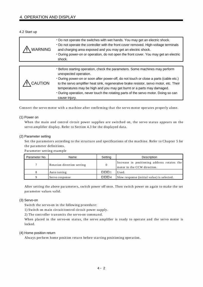
(2) Parameter settingSet the parameters according to the structure and specifications of the machine. Refer to Chapter 5 forthe parameter definitions.Parameter setting example
Parameter No. Name Setting Description
7 Rotation direction setting 0Increase in positioning address rotates themotor in the CCW direction.
8 Auto tuning 1 Used.9 Servo response 4 Slow response (initial value) is selected.
After setting the above parameters, switch power off once. Then switch power on again to make the setparameter values valid.
(3) Servo-onSwitch the servo-on in the following procedure:1) Switch on main circuit/control circuit power supply.2) The controller transmits the servo-on command.When placed in the servo-on status, the servo amplifier is ready to operate and the servo motor islocked.
(4) Home position returnAlways perform home position return before starting positioning operation.
4 - 3
4. OPERATION AND DISPLAY
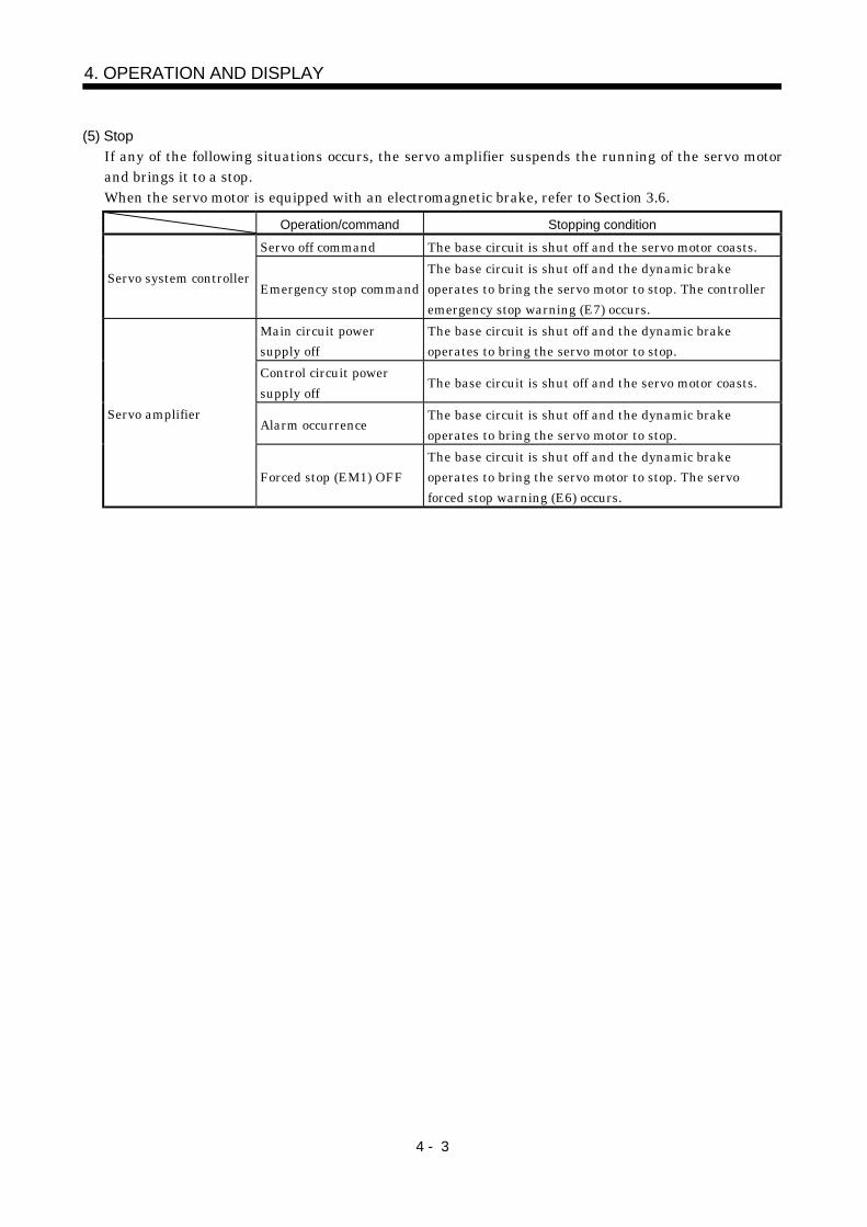
(5) StopIf any of the following situations occurs, the servo amplifier suspends the running of the servo motorand brings it to a stop.When the servo motor is equipped with an electromagnetic brake, refer to Section 3.6.
Operation/command Stopping condition
Servo off command The base circuit is shut off and the servo motor coasts.
Servo system controllerEmergency stop command
The base circuit is shut off and the dynamic brakeoperates to bring the servo motor to stop. The controlleremergency stop warning (E7) occurs.
Main circuit powersupply off
The base circuit is shut off and the dynamic brakeoperates to bring the servo motor to stop.
Control circuit powersupply off
The base circuit is shut off and the servo motor coasts.
Alarm occurrenceThe base circuit is shut off and the dynamic brakeoperates to bring the servo motor to stop.
Servo amplifier
Forced stop (EM1) OFFThe base circuit is shut off and the dynamic brakeoperates to bring the servo motor to stop. The servoforced stop warning (E6) occurs.
4 - 4
4. OPERATION AND DISPLAY
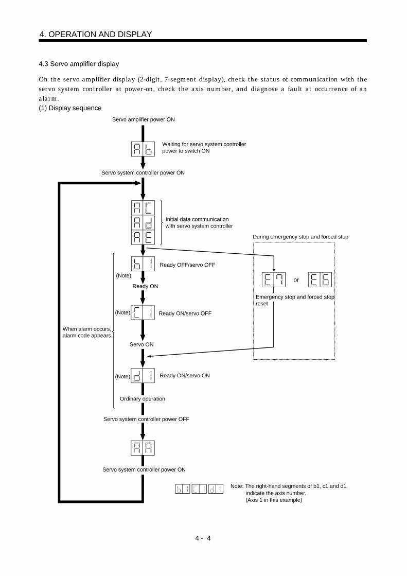
4.3 Servo amplifier display
On the servo amplifier display (2-digit, 7-segment display), check the status of communication with theservo system controller at power-on, check the axis number, and diagnose a fault at occurrence of analarm.(1) Display sequence
Servo amplifier power ON
Waiting for servo system controllerpower to switch ON
Servo system controller power ON
When alarm occurs,alarm code appears.
Ready ON
Ready OFF/servo OFF
Ready ON/servo OFF
Servo ON
Ordinary operation
Servo system controller power OFF
Ready ON/servo ON
(Note)
(Note)
(Note)
Servo system controller power ON
During emergency stop and forced stop
Emergency stop and forced stopreset
or
Note: The right-hand segments of b1, c1 and d1 indicate the axis number. (Axis 1 in this example)
Initial data communicationwith servo system controller
4 - 5
4. OPERATION AND DISPLAY
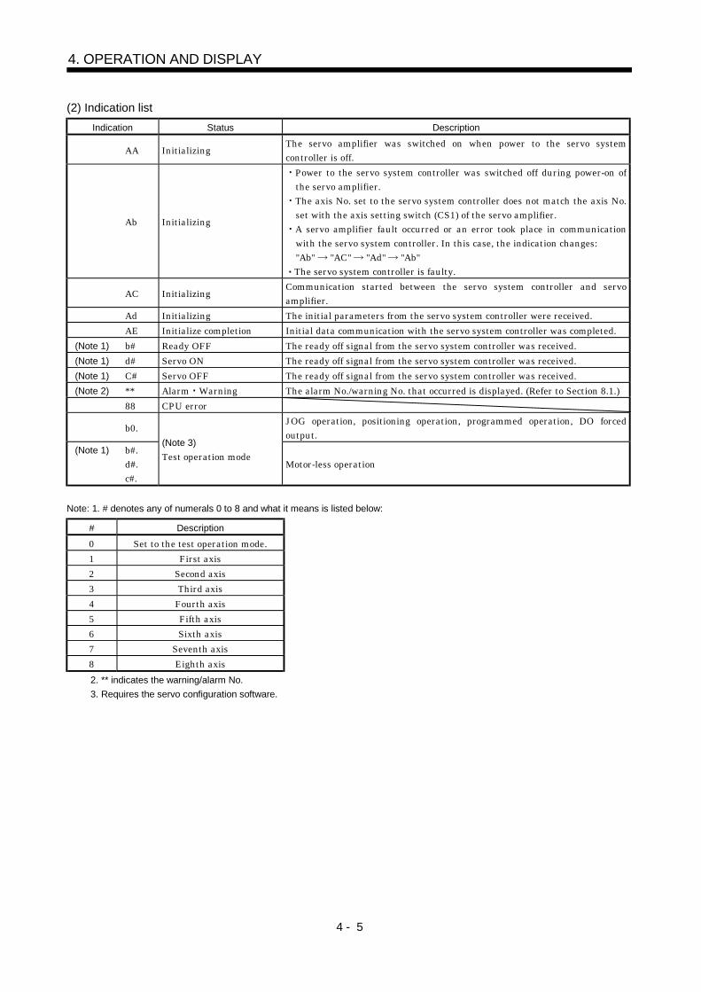
(2) Indication listIndication Status Description
AA Initializing The servo amplifier was switched on when power to the servo systemcontroller is off.
Ab Initializing
Power to the servo system controller was switched off during power-on ofthe servo amplifier.The axis No. set to the servo system controller does not match the axis No.set with the axis setting switch (CS1) of the servo amplifier.A servo amplifier fault occurred or an error took place in communicationwith the servo system controller. In this case, the indication changes:"Ab" "AC" "Ad" "Ab"The servo system controller is faulty.
AC Initializing Communication started between the servo system controller and servoamplifier.
Ad Initializing The initial parameters from the servo system controller were received.AE Initialize completion Initial data communication with the servo system controller was completed.
(Note 1) b# Ready OFF The ready off signal from the servo system controller was received.(Note 1) d# Servo ON The ready off signal from the servo system controller was received.(Note 1) C# Servo OFF The ready off signal from the servo system controller was received.(Note 2) ** Alarm Warning The alarm No./warning No. that occurred is displayed. (Refer to Section 8.1.)
88 CPU error
b0. JOG operation, positioning operation, programmed operation, DO forcedoutput.
(Note 1) b#.d#.c#.
(Note 3)Test operation mode
Motor-less operation
Note: 1. # denotes any of numerals 0 to 8 and what it means is listed below:
# Description0 Set to the test operation mode.1 First axis2 Second axis3 Third axis4 Fourth axis5 Fifth axis6 Sixth axis7 Seventh axis8 Eighth axis2. ** indicates the warning/alarm No.3. Requires the servo configuration software.
4 - 6
4. OPERATION AND DISPLAY
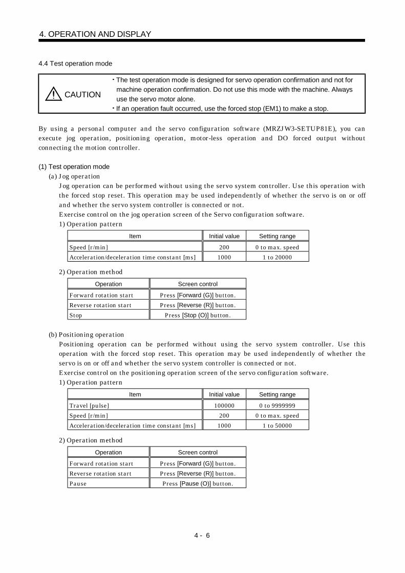
4.4 Test operation mode
CAUTION
The test operation mode is designed for servo operation confirmation and not formachine operation confirmation. Do not use this mode with the machine. Alwaysuse the servo motor alone.If an operation fault occurred, use the forced stop (EM1) to make a stop.
By using a personal computer and the servo configuration software (MRZJW3-SETUP81E), you canexecute jog operation, positioning operation, motor-less operation and DO forced output withoutconnecting the motion controller.
(1) Test operation mode(a) Jog operation
Jog operation can be performed without using the servo system controller. Use this operation withthe forced stop reset. This operation may be used independently of whether the servo is on or offand whether the servo system controller is connected or not.Exercise control on the jog operation screen of the Servo configuration software.1) Operation pattern
Item Initial value Setting range
Speed [r/min] 200 0 to max. speedAcceleration/deceleration time constant [ms] 1000 1 to 20000
2) Operation methodOperation Screen control
Forward rotation start Press [Forward (G)] button.Reverse rotation start Press [Reverse (R)] button.Stop Press [Stop (O)] button.
(b) Positioning operationPositioning operation can be performed without using the servo system controller. Use thisoperation with the forced stop reset. This operation may be used independently of whether theservo is on or off and whether the servo system controller is connected or not.Exercise control on the positioning operation screen of the servo configuration software.1) Operation pattern
Item Initial value Setting range
Travel [pulse] 100000 0 to 9999999Speed [r/min] 200 0 to max. speedAcceleration/deceleration time constant [ms] 1000 1 to 50000
2) Operation methodOperation Screen control
Forward rotation start Press [Forward (G)] button.Reverse rotation start Press [Reverse (R)] button.Pause Press [Pause (O)] button.
4 - 7
4. OPERATION AND DISPLAY
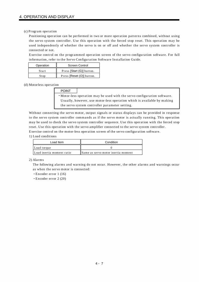
(c) Program operationPositioning operation can be performed in two or more operation patterns combined, without usingthe servo system controller. Use this operation with the forced stop reset. This operation may beused independently of whether the servo is on or off and whether the servo system controller isconnected or not.Exercise control on the programmed operation screen of the servo configuration software. For fullinformation, refer to the Servo Configuration Software Installation Guide.
Operation Screen Control
Start Press [Start (G)] button.Stop Press [Reset (O)] button.
(d) Motorless operationPOINTMotor-less operation may be used with the servo configuration software.Usually, however, use motor-less operation which is available by makingthe servo system controller parameter setting.
Without connecting the servo motor, output signals or status displays can be provided in responseto the servo system controller commands as if the servo motor is actually running. This operationmay be used to check the servo system controller sequence. Use this operation with the forced stopreset. Use this operation with the servo amplifier connected to the servo system controller.Exercise control on the motor-less operation screen of the servo configuration software.1) Load conditions
Load Item Condition
Load torque 0Load inertia moment ratio Same as servo motor inertia moment
2) AlarmsThe following alarms and warning do not occur. However, the other alarms and warnings occuras when the servo motor is connected:
Encoder error 1 (16)Encoder error 2 (20)
4 - 8
4. OPERATION AND DISPLAY
(2) ConfigurationConfiguration should be as in Section 3.1. Always install a forced stop switch to enable a stop atoccurrence of an alarm.
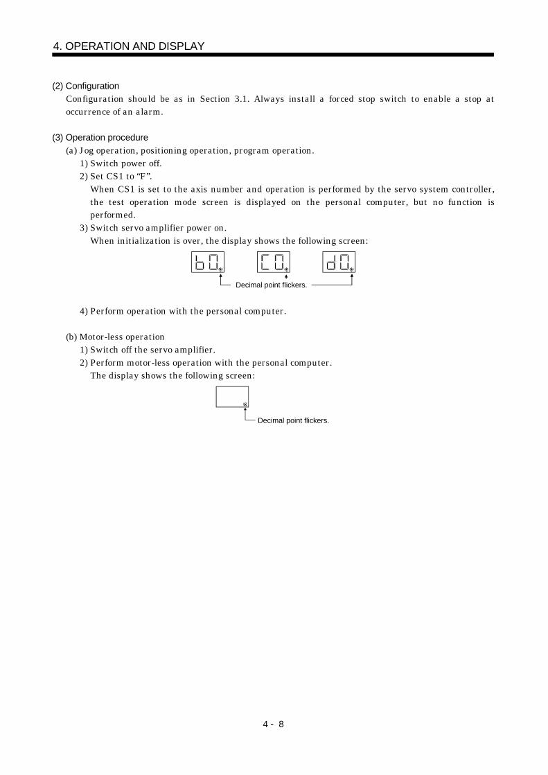
(3) Operation procedure(a) Jog operation, positioning operation, program operation.
1) Switch power off.2) Set CS1 to “F”.
When CS1 is set to the axis number and operation is performed by the servo system controller,the test operation mode screen is displayed on the personal computer, but no function isperformed.
3) Switch servo amplifier power on.When initialization is over, the display shows the following screen:
Decimal point flickers.
4) Perform operation with the personal computer.
(b) Motor-less operation1) Switch off the servo amplifier.2) Perform motor-less operation with the personal computer.
The display shows the following screen:
Decimal point flickers.
5 - 1
5. PARAMETERS
5. PARAMETERS
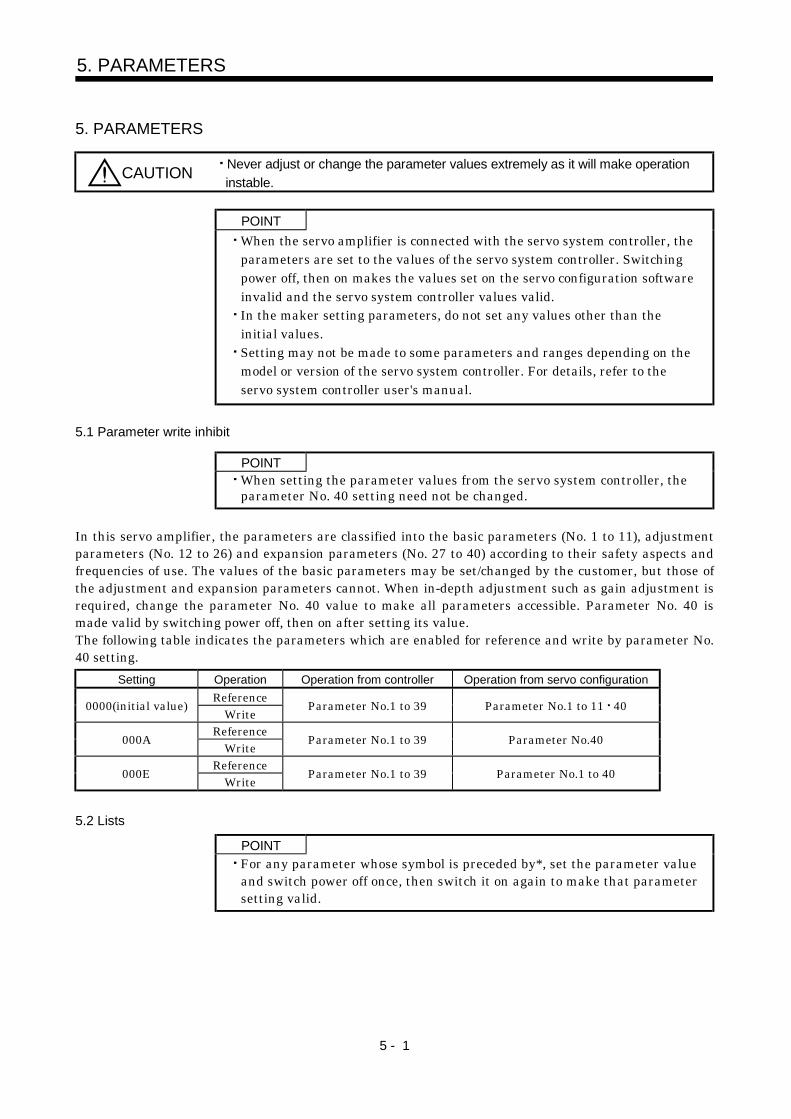
CAUTION Never adjust or change the parameter values extremely as it will make operationinstable.
POINTWhen the servo amplifier is connected with the servo system controller, theparameters are set to the values of the servo system controller. Switchingpower off, then on makes the values set on the servo configuration softwareinvalid and the servo system controller values valid.In the maker setting parameters, do not set any values other than theinitial values.Setting may not be made to some parameters and ranges depending on themodel or version of the servo system controller. For details, refer to theservo system controller user's manual.
5.1 Parameter write inhibit
POINTWhen setting the parameter values from the servo system controller, theparameter No. 40 setting need not be changed.
In this servo amplifier, the parameters are classified into the basic parameters (No. 1 to 11), adjustmentparameters (No. 12 to 26) and expansion parameters (No. 27 to 40) according to their safety aspects andfrequencies of use. The values of the basic parameters may be set/changed by the customer, but those ofthe adjustment and expansion parameters cannot. When in-depth adjustment such as gain adjustment isrequired, change the parameter No. 40 value to make all parameters accessible. Parameter No. 40 ismade valid by switching power off, then on after setting its value.The following table indicates the parameters which are enabled for reference and write by parameter No.40 setting.
Setting Operation Operation from controller Operation from servo configurationReference0000(initial value) Write Parameter No.1 to 39 Parameter No.1 to 11 40
Reference000A Write Parameter No.1 to 39 Parameter No.40
Reference000E Write Parameter No.1 to 39 Parameter No.1 to 40
5.2 Lists
POINTFor any parameter whose symbol is preceded by*, set the parameter valueand switch power off once, then switch it on again to make that parametersetting valid.
5 - 2
5. PARAMETERS
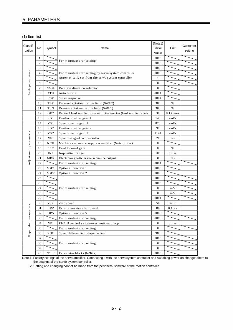
(1) Item list
Classifi-cation
No. Symbol Name(Note1)InitialValue
UnitCustomer
setting
1 00002
For manufacturer setting0000
3 00804 00005 16
For manufacturer setting by servo system controllerAutomatically set from the servo system controller
07 *POL Rotation direction selection 08 ATU Auto tuning 00019 RSP Servo response 000410 TLP Forward rotation torque limit (Note 2) 300 %
Basi
c par
amet
ers
11 TLN Reverse rotation torque limit (Note 2) 300 %12 GD2 Ratio of load inertia to servo motor inertia (load inertia ratio) 30 0.1 times13 PG1 Position control gain 1 145 rad/s14 VG1 Speed control gain 1 873 rad/s15 PG2 Position control gain 2 97 rad/s16 VG2 Speed control gain 2 1144 rad/s17 VIC Speed integral compensation 20 ms18 NCH Machine resonance suppression filter (Notch filter) 019 FFC Feed forward gain 0 %20 INP In-position range 100 pulse21 MBR Electromagnetic brake sequence output 0 ms22 For manufacturer setting 000123 *OP1 Optional function 1 000024 *OP2 Optional function 2 000025 0000
Adju
stm
ent p
aram
eter
s
26 000027 0 mV28 0 mV29
For manufacturer setting
000130 ZSP Zero speed 50 r/min31 ERZ Error excessive alarm level 80 0.1rev32 OP5 Optional function 5 000033 For manufacturer setting 000034 VPI PI-PID control switch-over position droop 0 pulse35 For manufacturer setting 036 VDC Speed differential compensation 98037 000038 039
For manufacturer setting0
Expa
nsio
n pa
ram
eter
s
40 *BLK Parameter blocks (Note 2) 0000Note 1: Factory settings of the servo amplifier. Connecting it with the servo system controller and switching power on changes them to
the settings of the servo system controller.2: Setting and changing cannot be made from the peripheral software of the motion controller.
5 - 3
5. PARAMETERS
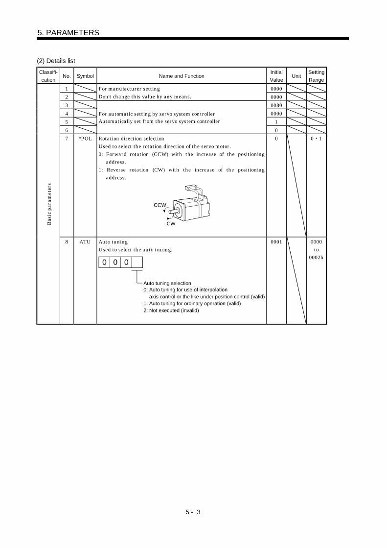
(2) Details listClassifi-cation
No. Symbol Name and FunctionInitialValue
UnitSettingRange
1 00002
For manufacturer settingDon't change this value by any means. 0000
3 00804 00005 16
For automatic setting by servo system controllerAutomatically set from the servo system controller
07 *POL Rotation direction selection
Used to select the rotation direction of the servo motor.0: Forward rotation (CCW) with the increase of the positioning
address.1: Reverse rotation (CW) with the increase of the positioning
address.
CCW
CW
0 0 1
Basi
c par
amet
ers
8 ATU Auto tuningUsed to select the auto tuning.
Auto tuning selection
0 00
0: Auto tuning for use of interpolation axis control or the like under position control (valid)1: Auto tuning for ordinary operation (valid)2: Not executed (invalid)
0001 0000to
0002h
5 - 4
5. PARAMETERS
Classifi-cation
No. Symbol Name and FunctionInitialValue
UnitSettingRange
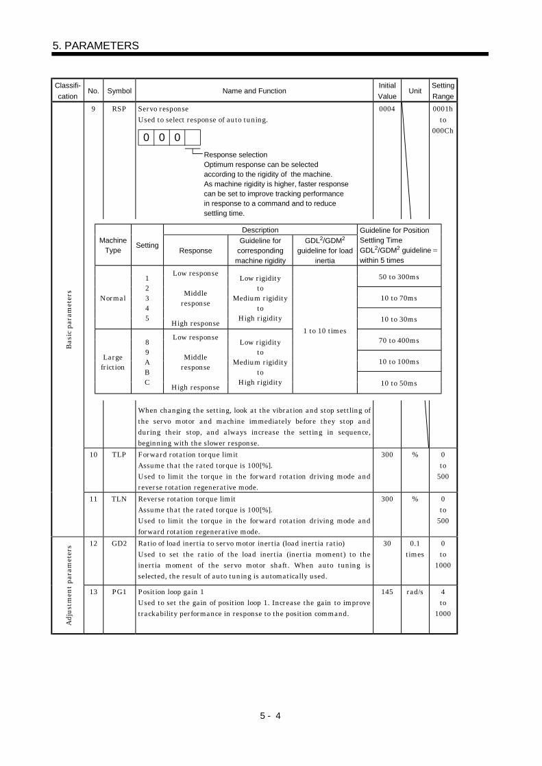
9 RSP Servo responseUsed to select response of auto tuning.
0 00Response selectionOptimum response can be selectedaccording to the rigidity of the machine.As machine rigidity is higher, faster responsecan be set to improve tracking performancein response to a command and to reducesettling time.
When changing the setting, look at the vibration and stop settling ofthe servo motor and machine immediately before they stop andduring their stop, and always increase the setting in sequence,beginning with the slower response.
0004 0001hto
000Ch
10 TLP Forward rotation torque limitAssume that the rated torque is 100[%].Used to limit the torque in the forward rotation driving mode andreverse rotation regenerative mode.
300 % 0to
500
Basi
c par
amet
ers
11 TLN Reverse rotation torque limitAssume that the rated torque is 100[%].Used to limit the torque in the forward rotation driving mode andforward rotation regenerative mode.
300 % 0to
500
12 GD2 Ratio of load inertia to servo motor inertia (load inertia ratio)Used to set the ratio of the load inertia (inertia moment) to theinertia moment of the servo motor shaft. When auto tuning isselected, the result of auto tuning is automatically used.
30 0.1times
0to
1000
Adju
stm
ent p
aram
eter
s
13 PG1 Position loop gain 1Used to set the gain of position loop 1. Increase the gain to improvetrackability performance in response to the position command.
145 rad/s 4to
1000
DescriptionMachine
TypeSetting
ResponseGuideline for
correspondingmachine rigidity
GDL2/GDM2
guideline for loadinertia
Guideline for PositionSettling TimeGDL2/GDM2 guideline within 5 times
50 to 300ms
10 to 70msNormal
12345
Low response
Middleresponse
High response
Low rigidityto
Medium rigidityto
High rigidity 10 to 30ms
70 to 400ms
10 to 100msLargefriction
89ABC
Low response
Middleresponse
High response
Low rigidityto
Medium rigidityto
High rigidity
1 to 10 times
10 to 50ms
5 - 5
5. PARAMETERS
Classifi-cation
No. Symbol Name and FunctionInitialValue
UnitSettingRange
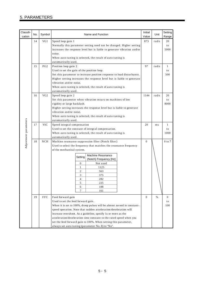
14 VG1 Speed loop gain 1Normally this parameter setting need not be changed. Higher settingincreases the response level but is liable to generate vibration and/ornoise.When auto tuning is selected, the result of auto tuning isautomatically used.
873 rad/s 20to
5000
15 PG2 Position loop gain 2Used to set the gain of the position loop.Set this parameter to increase position response to load disturbance.Higher setting increases the response level but is liable to generatevibration and/or noise.When auto tuning is selected, the result of auto tuning isautomatically used.
97 rad/s 1to
500
16 VG2 Speed loop gain 2Set this parameter when vibration occurs on machines of lowrigidity or large backlash.Higher setting increases the response level but is liable to generatevibration and/or noise.When auto tuning is selected, the result of auto tuning isautomatically used.
1144 rad/s 20to
8000
17 VIC Speed integral compensationUsed to set the constant of integral compensation.When auto tuning is selected, the result of auto tuning isautomatically used.
20 ms 1to
1000
18 NCH Machine resonance suppression filter (Notch filter)Used to select the frequency that matches the resonance frequencyof the mechanical system.
01234567
Setting Machine Resonance(Notch) Frequency [Hz]
Not used1125563375282225188161
0 0 to 7
Adju
stm
ent p
aram
eter
s
19 FFC Feed forward gainUsed to set the feed forward gain.When it is set to 100%, droop pulses will be almost zeroed in constant-speed operation. Note that sudden acceleration/deceleration willincrease overshoot. As a guideline, specify 1s or more as theacceleration/deceleration time constant to the rated speed when youset the feed forward gain to 100%. When setting this parameter,always set auto tuning (parameter No. 8) to "No".
0 % 0to
100
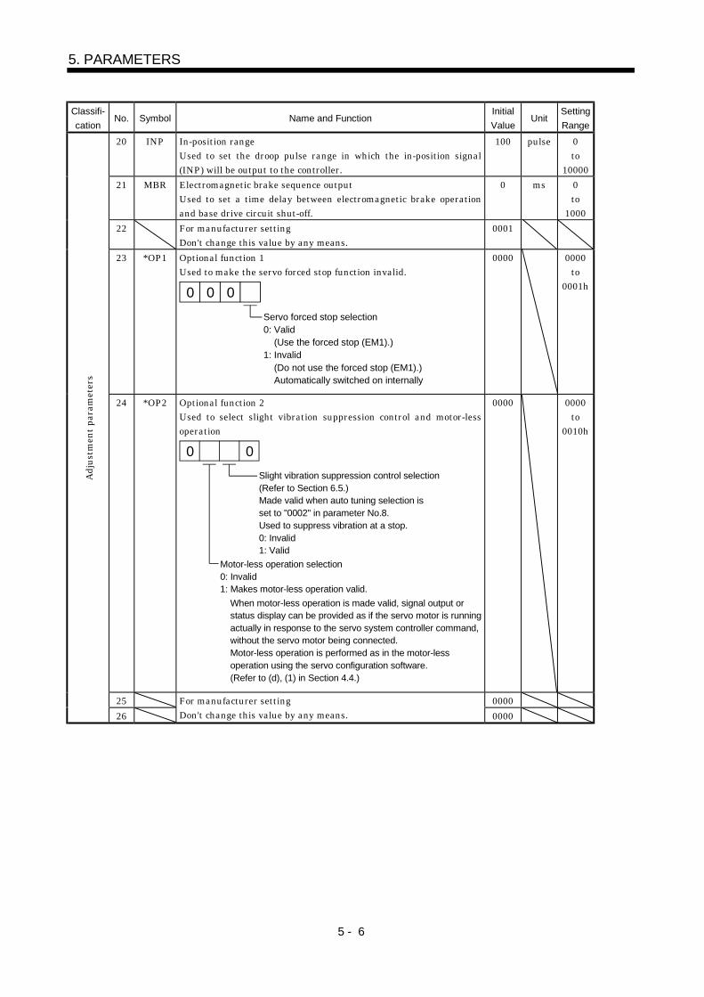
5 - 6
5. PARAMETERS
Classifi-cation
No. Symbol Name and FunctionInitialValue
UnitSettingRange
20 INP In-position rangeUsed to set the droop pulse range in which the in-position signal(INP) will be output to the controller.
100 pulse 0to
1000021 MBR Electromagnetic brake sequence output
Used to set a time delay between electromagnetic brake operationand base drive circuit shut-off.
0 ms 0to
100022 For manufacturer setting
Don't change this value by any means.0001
23 *OP1 Optional function 1Used to make the servo forced stop function invalid.
Servo forced stop selection0: Valid (Use the forced stop (EM1).) 1: Invalid (Do not use the forced stop (EM1).) Automatically switched on internally
00 0
0000 0000to
0001h
24 *OP2 Optional function 2Used to select slight vibration suppression control and motor-lessoperation
Slight vibration suppression control selection(Refer to Section 6.5.)Made valid when auto tuning selection isset to "0002" in parameter No.8.Used to suppress vibration at a stop.0: Invalid1: Valid
Motor-less operation selection0: Invalid1: Makes motor-less operation valid.
When motor-less operation is made valid, signal output orstatus display can be provided as if the servo motor is runningactually in response to the servo system controller command, without the servo motor being connected.Motor-less operation is performed as in the motor-lessoperation using the servo configuration software.(Refer to (d), (1) in Section 4.4.)
0 0
0000 0000to
0010h
25 0000
Adju
stm
ent p
aram
eter
s
26For manufacturer settingDon't change this value by any means. 0000
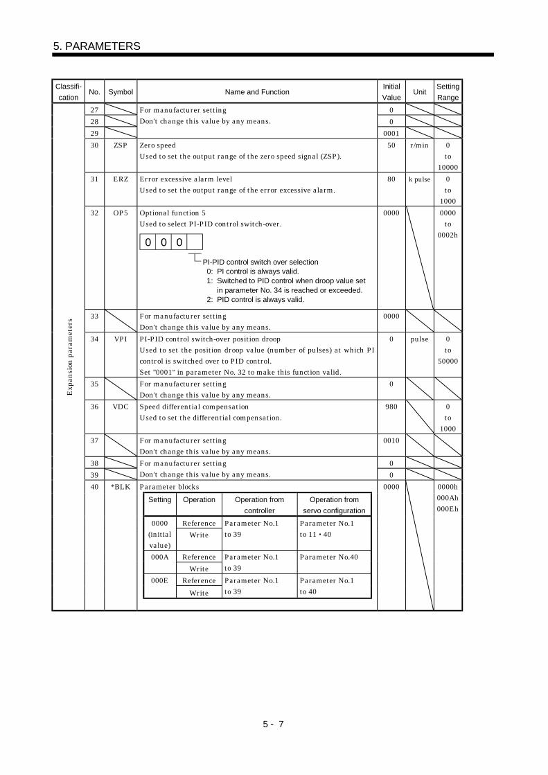
5 - 7
5. PARAMETERS
Classifi-cation
No. Symbol Name and FunctionInitialValue
UnitSettingRange
27 028 029
For manufacturer settingDon't change this value by any means.
000130 ZSP Zero speed
Used to set the output range of the zero speed signal (ZSP).50 r/min 0
to10000
31 ERZ Error excessive alarm levelUsed to set the output range of the error excessive alarm.
80 k pulse 0to
100032 OP5 Optional function 5
Used to select PI-PID control switch-over.
PI-PID control switch over selection 0: PI control is always valid. 1: Switched to PID control when droop value set in parameter No. 34 is reached or exceeded. 2: PID control is always valid.
0 00
0000 0000to
0002h
33 For manufacturer settingDon't change this value by any means.
0000
34 VPI PI-PID control switch-over position droopUsed to set the position droop value (number of pulses) at which PIcontrol is switched over to PID control.Set "0001" in parameter No. 32 to make this function valid.
0 pulse 0to
50000
35 For manufacturer settingDon't change this value by any means.
0
36 VDC Speed differential compensationUsed to set the differential compensation.
980 0to
100037 For manufacturer setting
Don't change this value by any means.0010
38 039
For manufacturer settingDon't change this value by any means. 0Parameter blocks
Setting Operation Operation fromcontroller
Operation fromservo configuration
Reference0000(initialvalue)
WriteParameter No.1to 39
Parameter No.1to 11 40
Reference000AWrite
Parameter No.1to 39
Parameter No.40
Reference000EWrite
Parameter No.1to 39
Parameter No.1to 40
Expa
nsio
n pa
ram
eter
s
40 *BLK 0000 0000h000Ah000Eh

5 - 8
5. PARAMETERS
MEMO
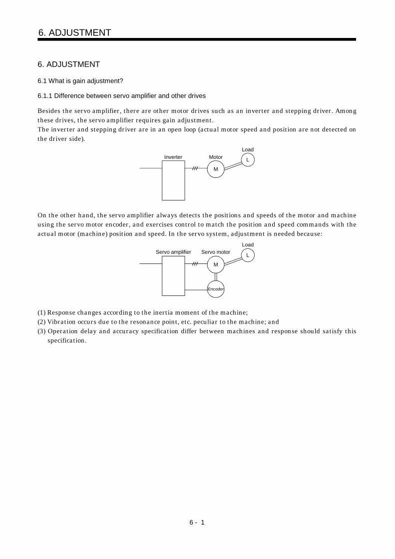
6 - 1
6. ADJUSTMENT
6. ADJUSTMENT
6.1 What is gain adjustment?
6.1.1 Difference between servo amplifier and other drives
Besides the servo amplifier, there are other motor drives such as an inverter and stepping driver. Amongthese drives, the servo amplifier requires gain adjustment.The inverter and stepping driver are in an open loop (actual motor speed and position are not detected onthe driver side).
M
L
LoadMotorInverter
On the other hand, the servo amplifier always detects the positions and speeds of the motor and machineusing the servo motor encoder, and exercises control to match the position and speed commands with theactual motor (machine) position and speed. In the servo system, adjustment is needed because:
M
LServo amplifierLoad
Encoder
Servo motor
(1) Response changes according to the inertia moment of the machine;(2) Vibration occurs due to the resonance point, etc. peculiar to the machine; and(3) Operation delay and accuracy specification differ between machines and response should satisfy this
specification.
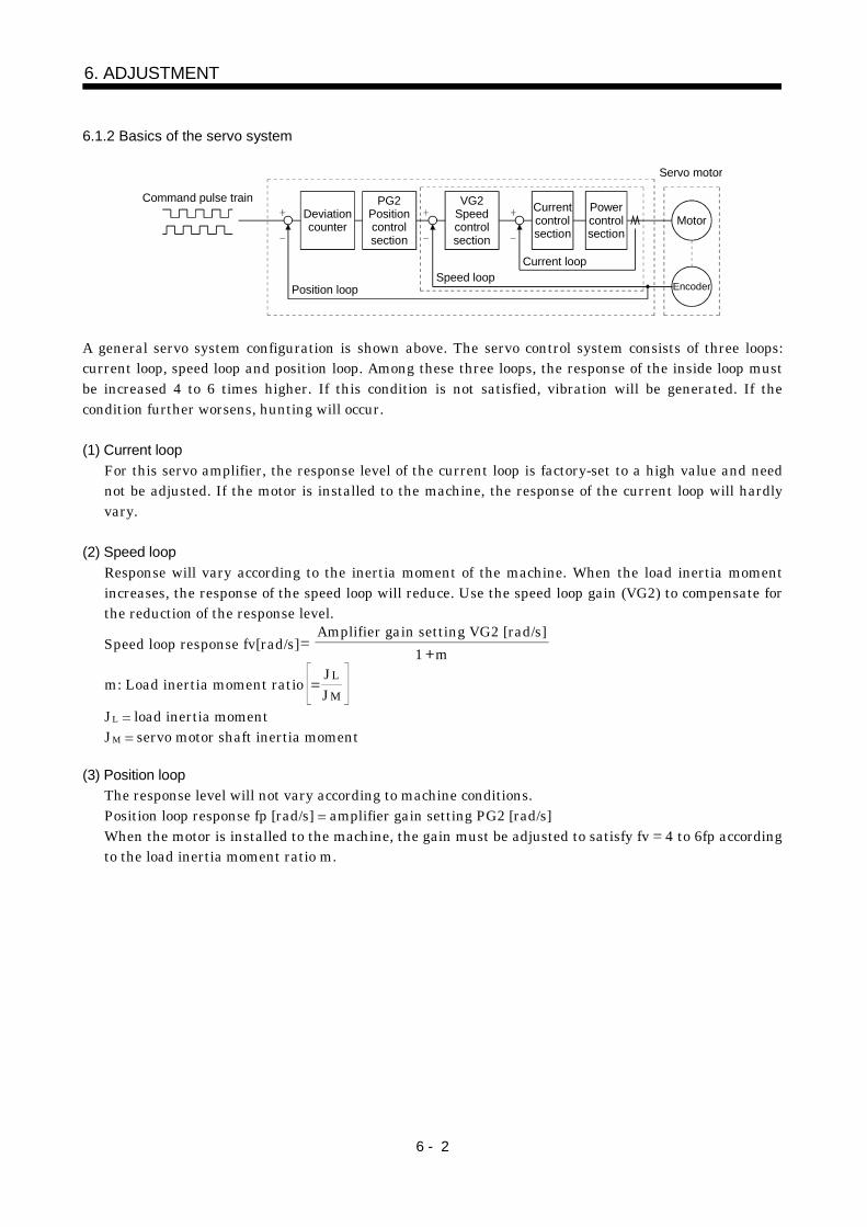
6 - 2
6. ADJUSTMENT
6.1.2 Basics of the servo system
Encoder
Deviationcounter
PG2Positioncontrolsection
VG2Speedcontrolsection
Currentcontrolsection
Powercontrolsection
Current loopSpeed loop
Position loop
Servo motor
Motor
Command pulse train
A general servo system configuration is shown above. The servo control system consists of three loops:current loop, speed loop and position loop. Among these three loops, the response of the inside loop mustbe increased 4 to 6 times higher. If this condition is not satisfied, vibration will be generated. If thecondition further worsens, hunting will occur.
(1) Current loopFor this servo amplifier, the response level of the current loop is factory-set to a high value and neednot be adjusted. If the motor is installed to the machine, the response of the current loop will hardlyvary.
(2) Speed loopResponse will vary according to the inertia moment of the machine. When the load inertia momentincreases, the response of the speed loop will reduce. Use the speed loop gain (VG2) to compensate forthe reduction of the response level.
Speed loop response fv[rad/s]Amplifier gain setting VG2 [rad/s]
1 m
m: Load inertia moment ratio JMJL
JL load inertia momentJM servo motor shaft inertia moment
(3) Position loopThe response level will not vary according to machine conditions.Position loop response fp [rad/s] amplifier gain setting PG2 [rad/s]When the motor is installed to the machine, the gain must be adjusted to satisfy fv 4 to 6fp accordingto the load inertia moment ratio m.
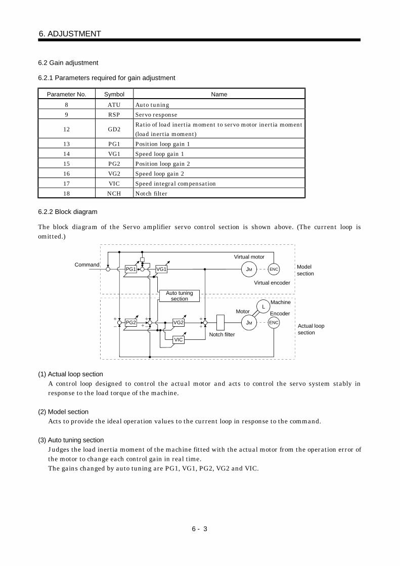
6 - 3
6. ADJUSTMENT
6.2 Gain adjustment
6.2.1 Parameters required for gain adjustment
Parameter No. Symbol Name
8 ATU Auto tuning9 RSP Servo response
12 GD2Ratio of load inertia moment to servo motor inertia moment(load inertia moment)
13 PG1 Position loop gain 114 VG1 Speed loop gain 115 PG2 Position loop gain 216 VG2 Speed loop gain 217 VIC Speed integral compensation18 NCH Notch filter
6.2.2 Block diagram
The block diagram of the Servo amplifier servo control section is shown above. (The current loop isomitted.)
PG1 VG1
PG2 VG2
VIC
JM ENC
L
JM ENC
Command
Actual loopsection
Virtual motor
Virtual encoder
MachineMotor Encoder
Model section
Auto tuningsection
Notch filter
(1) Actual loop sectionA control loop designed to control the actual motor and acts to control the servo system stably inresponse to the load torque of the machine.
(2) Model sectionActs to provide the ideal operation values to the current loop in response to the command.
(3) Auto tuning sectionJudges the load inertia moment of the machine fitted with the actual motor from the operation error ofthe motor to change each control gain in real time.The gains changed by auto tuning are PG1, VG1, PG2, VG2 and VIC.
6 - 4
6. ADJUSTMENT
6.2.3 What is auto tuning?
The load inertia moment is estimated from the angular speed ( ) and torque (T) in accordance with theequation of motion (6.1) used for motor acceleration/deceleration. In actuality, the acceleration/deceleration characteristics of the model and those of the actual motor are compared to estimate theinertia moment of the load in real time.
J dtd T................................................................ (6.1)
J : Inertia moment : Angular speed
T : Torque
Real-time auto tuning is performed in the following procedure:(1) When the motor makes acceleration/deceleration, load inertia moment JL is estimated in the above
method to calculate the load inertia moment ratio (GD2).(2) Each gain (PG1, VG1, PG2, VG2, VIC) to the calculated load inertia moment ratio (GD2) is changed
according to the response level set in parameter No. 9. Note that these gains have been patternedbeforehand to satisfy the aforementioned stabilization condition.
6 - 5
6. ADJUSTMENT
6.3 Gain adjustment by auto tuning
6.3.1 Adjustment method
In the factory setting of the servo amplifier, auto tuning selection is valid (parameter No. 8: 0001) and theresponse selection is "4" (parameter No. 9: 0004).The initial settings provide sufficient tuning for general machines. Higher-level tuning can be provided byadjusting the response selection (parameter No. 9) according to machine rigidity.The following table lists guidelines for response selection to drive systems. Choose slow response whenusing a reduction gear having backlash:
Main drive system High response Middle response Low response
Direct couplingBallscrew
With reduction gearDirect coupling
Rack & pinionWith reduction gearDirect coupling
Timing beltWith reduction gearDirect coupling
ChainWith reduction gear
The following is how to adjust the response selection to machine phenomena:Actual machine operation Ideal machine operation Parameter No. 9 setting
Settling time is long (Note) Reduce settling time. Increase response setting.
Large overshoot at stop Reduce overshoot.Decrease response setting.Set machine selection setting to "large friction".
Gear sound generated from machine Reduce gear sound. Decrease response setting.Note: Settling time indicates time from zero command pulse to servo motor stop.
6.3.2 Valid conditions
POINTIf the acceleration/deceleration time is long or the servo motor speed usedis only low speed, the valid conditions of auto tuning are not satisfied.Therefore, it may result in false tuning.In this case, after performing operation which satisfies the auto tuningconditions, set auto tuning selection to "Not executed" (parameter No. 8:0002).
This section provides constraints on the operation pattern to enable excellent auto tuning. If theconditions in this section cannot be satisfied, normal auto tuning may not be performed. In this case, afterexecuting auto tuning in operation which satisfies the conditions given in this section, make auto tuninginvalid to disallow the gain setting from being changed.
(1) Set the acceleration time (time until the preset speed is reached) to 5s or less and the acceleration/deceleration current to 50% or more.
(2) Perform operation several times until the cumulative acceleration/deceleration time is 1s or more.(3) Set the servo motor speed to 500r/min or more.
6 - 6
6. ADJUSTMENT
6.4 Manual gain adjustment
On some machines, gain adjustment may not be made by auto tuning or excellent gain setting may not bemade if gain adjustment is performed by auto tuning. In this case, adjust the gains manually. Use any ofthe methods given in this section to adjust the gains.
6.4.1 When machine rigidity is low
(1) Machine conditionBecause of low machine rigidity, the response selection of auto tuning is set to low response and ittakes too much time to reach the target position.When the machine or motor shaft is moved lightly at a stop, it moves easily.
(2) Adjustment procedure(a) Adjustment 1
1) Execute auto tuning with the response selection of the level at which machine will not vibrate.Set parameter No. 8 to "0001" and parameter No. 9 to "0003" or less.
2) Set "Not executed" (parameter No. 8: 0002) by the auto tuning selection.3) Gradually decrease the speed integral compensation VIC (parameter No. 38) setting.
(b) Adjustment 21) Perform auto tuning with the response selection of low response.
Set parameter No. 8 to "0001" and parameter No. 9 to "0003" or less.2) Set the notch filter (parameter No. 18) in order from higher to lower frequencies.3) Alternate a start and a stop several times, execute auto tuning, and check whether the machine
does not vibrate.4) If the machine condition does not become excellent after the above adjustment, reduce the
setting of speed integral compensation (parameter No. 17) in Adjustment 1.
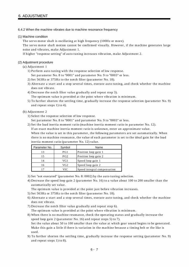
6 - 7
6. ADJUSTMENT
6.4.2 When the machine vibrates due to machine resonance frequency
(1) Machine conditionThe servo motor shaft is oscillating at high frequency (100Hz or more).The servo motor shaft motion cannot be confirmed visually. However, if the machine generates largenoise and vibrates, make Adjustment 1.If higher "response setting" of auto tuning increases vibration, make Adjustment 2.
(2) Adjustment procedure(a) Adjustment 1
1) Perform auto tuning with the response selection of low response.Set parameter No. 8 to "0001" and parameter No. 9 to "0003" or less.
2) Set 563Hz or 375Hz to the notch filter (parameter No. 18).3) Alternate a start and a stop several times, execute auto tuning, and check whether the machine
does not vibrate.4) Decrease the notch filter value gradually and repeat step 3).
The optimum value is provided at the point where vibration is minimum.5) To further shorten the settling time, gradually increase the response selection (parameter No. 9)
and repeat steps 1) to 4).
(b) Adjustment 21) Select the response selection of low response.
Set parameter No. 8 to "0001" and parameter No. 9 to "0003" or less.2) Set the load inertia moment ratio (machine inertia moment ratio in parameter No. 12).
If an exact machine inertia moment ratio is unknown, enter an approximate value.When the value is set in this parameter, the following parameters are set automatically. Whenthere is no machine resonance, the value of each parameter is set to the ideal gain for the loadinertia moment ratio (parameter No. 12) value.
Parameter No. Symbol Name13 PG1 Position loop gain 115 PG2 Position loop gain 214 VG1 Speed loop gain 116 VG2 Speed loop gain 217 VIC Speed integral compensation
3) Set "not executed" (parameter No. 8: 0002) by the auto tuning selection.4) Decrease the speed loop gain 2 (parameter No. 16) to a value about 100 to 200 smaller than the
automatically set value.The optimum value is provided at the point just before vibration increases.
5) Set 563Hz or 375Hz to the notch filter (parameter No. 18).6) Alternate a start and a stop several times, execute auto tuning, and check whether the machine
does not vibrate.7) Decrease the notch filter value gradually and repeat step 6).
The optimum value is provided at the point where vibration is minimum.8) When there is no machine resonance, check the operating status and gradually increase the
speed loop gain 2 (parameter No. 16) and repeat steps 5) to 7).Set the value about 50 to 100 smaller than the value at which gear sound begins to be generated.Make this gain a little if there is variation in the machine because a timing belt or the like isused.
9) To further shorten the settling time, gradually increase the response setting (parameter No. 9)and repeat steps 1) to 8).
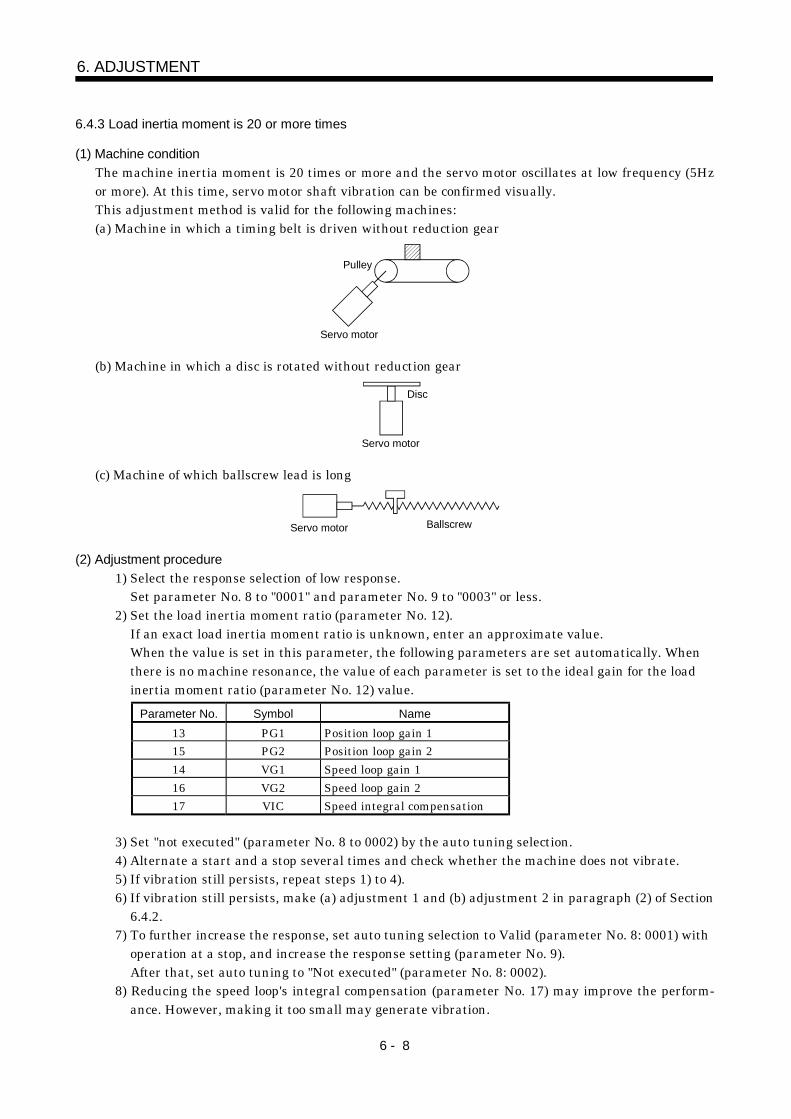
6 - 8
6. ADJUSTMENT
6.4.3 Load inertia moment is 20 or more times
(1) Machine conditionThe machine inertia moment is 20 times or more and the servo motor oscillates at low frequency (5Hzor more). At this time, servo motor shaft vibration can be confirmed visually.This adjustment method is valid for the following machines:(a) Machine in which a timing belt is driven without reduction gear
Servo motor
Pulley
(b) Machine in which a disc is rotated without reduction gear
Servo motor
Disc
(c) Machine of which ballscrew lead is long
BallscrewServo motor
(2) Adjustment procedure1) Select the response selection of low response.
Set parameter No. 8 to "0001" and parameter No. 9 to "0003" or less.2) Set the load inertia moment ratio (parameter No. 12).
If an exact load inertia moment ratio is unknown, enter an approximate value.When the value is set in this parameter, the following parameters are set automatically. Whenthere is no machine resonance, the value of each parameter is set to the ideal gain for the loadinertia moment ratio (parameter No. 12) value.
Parameter No. Symbol Name13 PG1 Position loop gain 115 PG2 Position loop gain 214 VG1 Speed loop gain 116 VG2 Speed loop gain 217 VIC Speed integral compensation
3) Set "not executed" (parameter No. 8 to 0002) by the auto tuning selection.4) Alternate a start and a stop several times and check whether the machine does not vibrate.5) If vibration still persists, repeat steps 1) to 4).6) If vibration still persists, make (a) adjustment 1 and (b) adjustment 2 in paragraph (2) of Section
6.4.2.7) To further increase the response, set auto tuning selection to Valid (parameter No. 8: 0001) with
operation at a stop, and increase the response setting (parameter No. 9).After that, set auto tuning to "Not executed" (parameter No. 8: 0002).
8) Reducing the speed loop's integral compensation (parameter No. 17) may improve the perform-ance. However, making it too small may generate vibration.
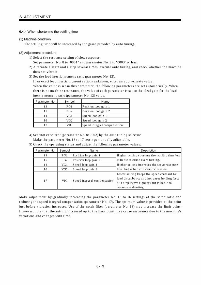
6 - 9
6. ADJUSTMENT
6.4.4 When shortening the settling time
(1) Machine conditionThe settling time will be increased by the gains provided by auto tuning.
(2) Adjustment procedure1) Select the response setting of slow response.
Set parameter No. 8 to "0001" and parameter No. 9 to "0003" or less.2) Alternate a start and a stop several times, execute auto tuning, and check whether the machine
does not vibrate.3) Set the load inertia moment ratio (parameter No. 12).
If an exact load inertia moment ratio is unknown, enter an approximate value.When the value is set in this parameter, the following parameters are set automatically. Whenthere is no machine resonance, the value of each parameter is set to the ideal gain for the loadinertia moment ratio (parameter No. 12) value.
Parameter No. Symbol Name13 PG1 Position loop gain 115 PG2 Position loop gain 214 VG1 Speed loop gain 116 VG2 Speed loop gain 217 VIC Speed integral compensation
4) Set "not executed" (parameter No. 8: 0002) by the auto tuning selection.Make the parameter No. 13 to 17 settings manually adjustable.
5) Check the operating status and adjust the following parameter values:Parameter No. Symbol Name Description
13 PG1 Position loop gain 115 PG2 Position loop gain 2
Higher setting shortens the settling time butis liable to cause overshooting.
14 VG1 Speed loop gain 116 VG2 Speed loop gain 2
Higher setting improves the servo responselevel but is liable to cause vibration.
17 VIC Speed integral compensation
Lower setting keeps the speed constant toload disturbance and increases holding forceat a stop (servo rigidity) but is liable tocause overshooting.
Make adjustment by gradually increasing the parameter No. 13 to 16 settings at the same ratio andreducing the speed integral compensation (parameter No. 17). The optimum value is provided at the pointjust before vibration increases. Use of the notch filter (parameter No. 18) may increase the limit point.However, note that the setting increased up to the limit point may cause resonance due to the machine'svariations and changes with time.
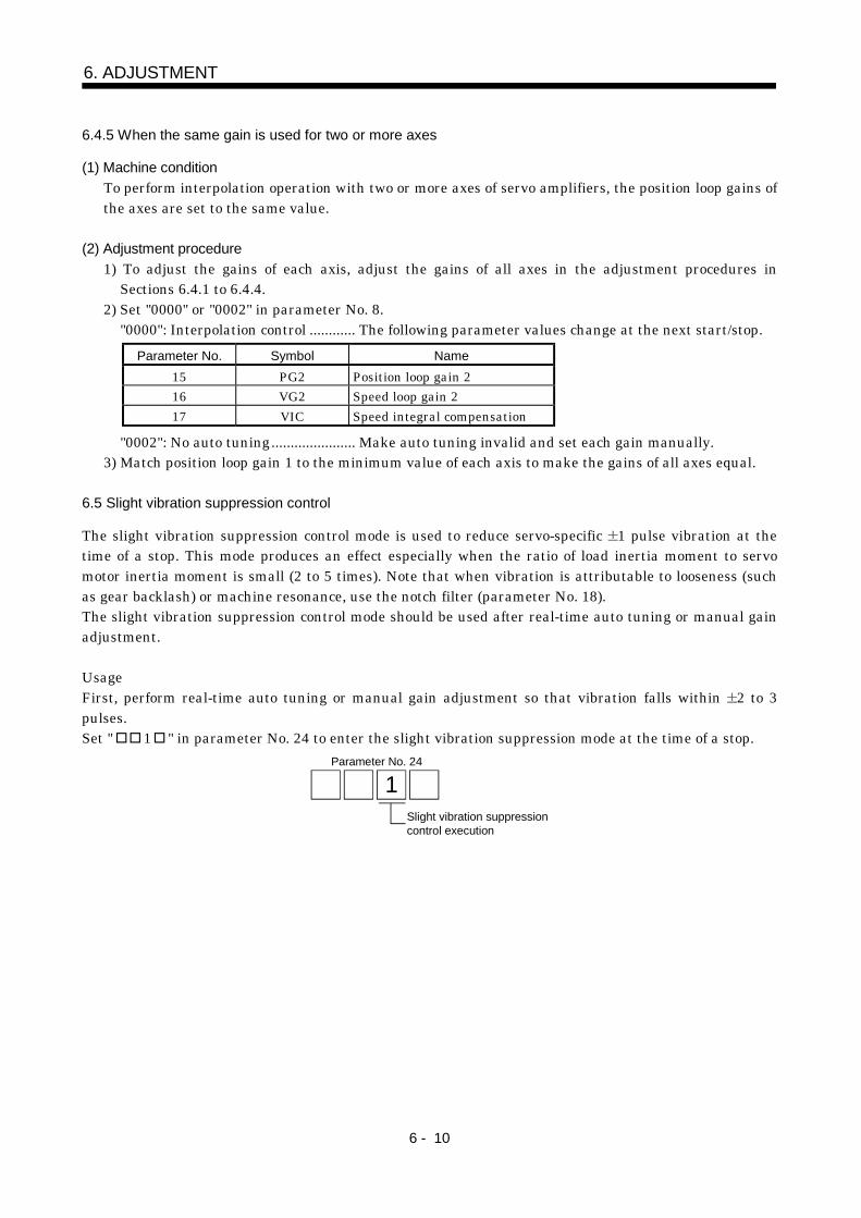
6 - 10
6. ADJUSTMENT
6.4.5 When the same gain is used for two or more axes
(1) Machine conditionTo perform interpolation operation with two or more axes of servo amplifiers, the position loop gains ofthe axes are set to the same value.
(2) Adjustment procedure1) To adjust the gains of each axis, adjust the gains of all axes in the adjustment procedures in
Sections 6.4.1 to 6.4.4.2) Set "0000" or "0002" in parameter No. 8.
"0000": Interpolation control ............ The following parameter values change at the next start/stop.Parameter No. Symbol Name
15 PG2 Position loop gain 216 VG2 Speed loop gain 217 VIC Speed integral compensation
"0002": No auto tuning...................... Make auto tuning invalid and set each gain manually.3) Match position loop gain 1 to the minimum value of each axis to make the gains of all axes equal.
6.5 Slight vibration suppression control
The slight vibration suppression control mode is used to reduce servo-specific 1 pulse vibration at thetime of a stop. This mode produces an effect especially when the ratio of load inertia moment to servomotor inertia moment is small (2 to 5 times). Note that when vibration is attributable to looseness (suchas gear backlash) or machine resonance, use the notch filter (parameter No. 18).The slight vibration suppression control mode should be used after real-time auto tuning or manual gainadjustment.
UsageFirst, perform real-time auto tuning or manual gain adjustment so that vibration falls within 2 to 3pulses.Set " 1 " in parameter No. 24 to enter the slight vibration suppression mode at the time of a stop.
Slight vibration suppressioncontrol execution
Parameter No. 24
1
7 - 1
7. INSPECTION
7. INSPECTION
WARNING
Before starting maintenance/inspection, switch power off, and after more than 10minutes have elapsed, confirm that the voltage is safe in the tester or the like.Otherwise, you may get an electric shock.Any person who is involved in inspection should be fully competent to do the work.Otherwise, you may get an electric shock. For repair and parts replacement,contact your safes representative.
POINTDo not test the servo amplifier with a megger (measure insulationresistance), or it may become faulty.Do not disassemble and/or repair the equipment on customer side.
(1) InspectionCheck the cables and the like for scratches and cracks. Perform periodic inspection according tooperating conditions.
(2) LifeThe following parts must be changed periodically as listed below. If any part is found faulty, it must bechanged immediately even when it has not yet reached the end of its life, which depends on theoperating method and environmental conditions.
Part name Life guideline
Smoothing capacitor 10 years
RelayNumber of power-on and number of emergency stoptimes : 100,000 times
(a) Smoothing capacitorAffected by ripple currents, etc. and deteriorates in characteristic. The life of the capacitor greatlydepends on ambient temperature and operating conditions. The capacitor will reach the end of itslife in 10 years of continuous operation in normal air-conditioned environment.
(b) RelaysTheir contacts will wear due to switching currents and contact faults occur. Relays reach the end oftheir life when the cumulative number of power-on and emergency stop times is 100,000, whichdepends on the power supply capacity.

7 - 2
7. INSPECTION
MEMO
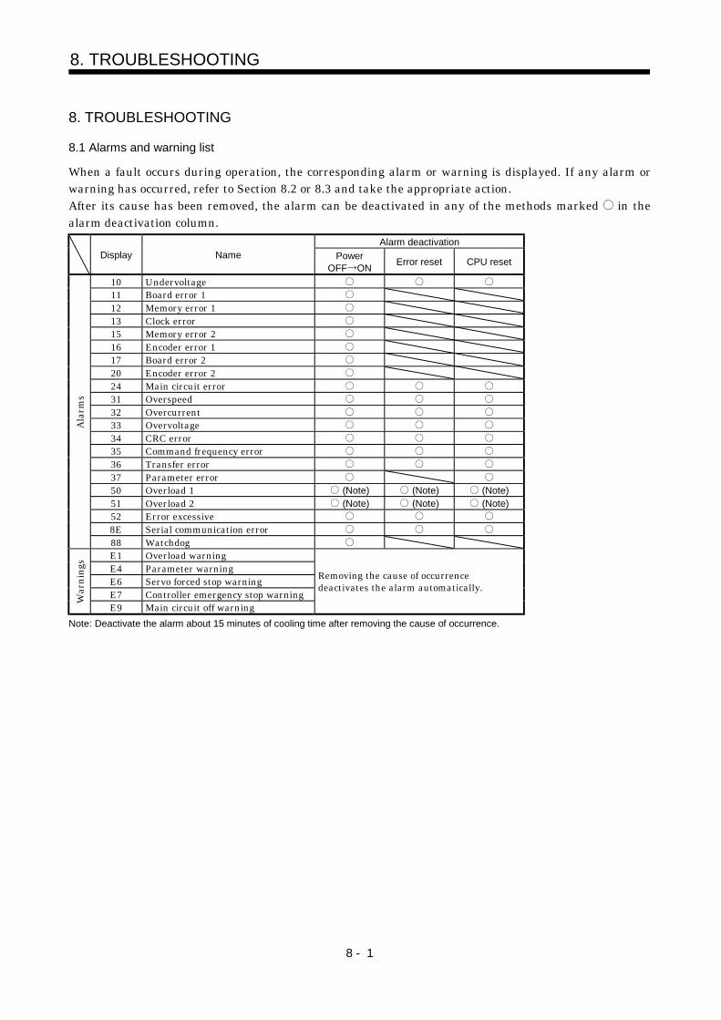
8 - 1
8. TROUBLESHOOTING
8. TROUBLESHOOTING
8.1 Alarms and warning list
When a fault occurs during operation, the corresponding alarm or warning is displayed. If any alarm orwarning has occurred, refer to Section 8.2 or 8.3 and take the appropriate action.After its cause has been removed, the alarm can be deactivated in any of the methods marked in thealarm deactivation column.
Alarm deactivationDisplay Name Power
OFF ON Error reset CPU reset
10 Undervoltage11 Board error 112 Memory error 113 Clock error15 Memory error 216 Encoder error 117 Board error 220 Encoder error 224 Main circuit error31 Overspeed32 Overcurrent33 Overvoltage34 CRC error35 Command frequency error36 Transfer error37 Parameter error50 Overload 1 (Note) (Note) (Note)51 Overload 2 (Note) (Note) (Note)52 Error excessive8E Serial communication error
Alar
ms
88 WatchdogE1 Overload warningE4 Parameter warningE6 Servo forced stop warningE7 Controller emergency stop warningW
arni
ngs
E9 Main circuit off warning
Removing the cause of occurrencedeactivates the alarm automatically.
Note: Deactivate the alarm about 15 minutes of cooling time after removing the cause of occurrence.
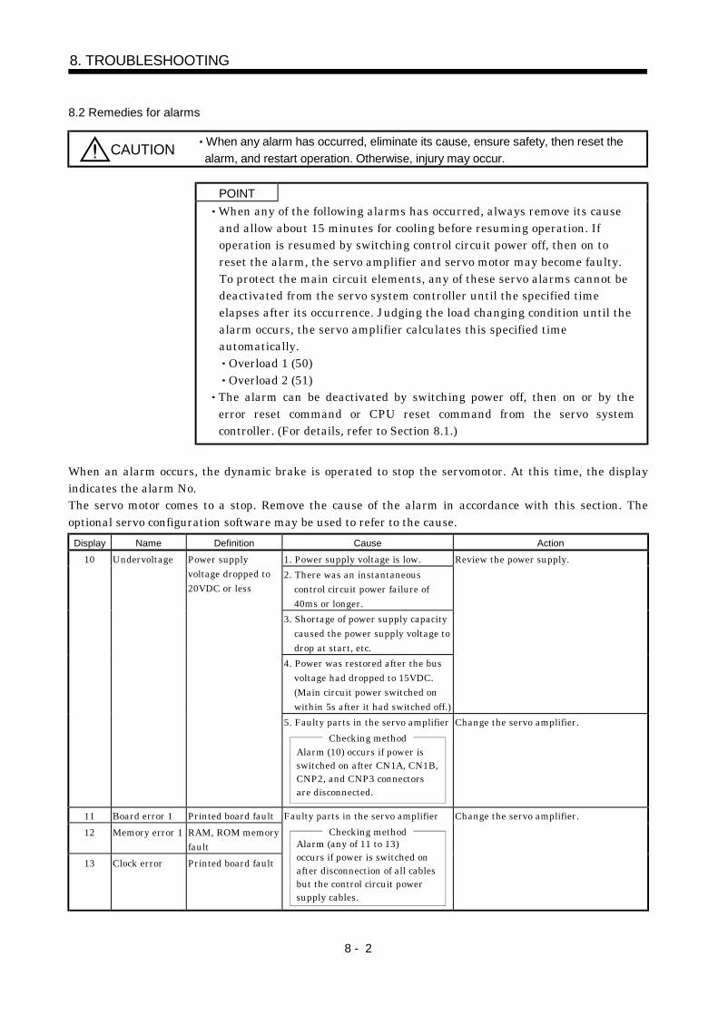
8 - 2
8. TROUBLESHOOTING
8.2 Remedies for alarms
CAUTION When any alarm has occurred, eliminate its cause, ensure safety, then reset thealarm, and restart operation. Otherwise, injury may occur.
POINTWhen any of the following alarms has occurred, always remove its causeand allow about 15 minutes for cooling before resuming operation. Ifoperation is resumed by switching control circuit power off, then on toreset the alarm, the servo amplifier and servo motor may become faulty.To protect the main circuit elements, any of these servo alarms cannot bedeactivated from the servo system controller until the specified timeelapses after its occurrence. Judging the load changing condition until thealarm occurs, the servo amplifier calculates this specified timeautomatically.
Overload 1 (50)Overload 2 (51)
The alarm can be deactivated by switching power off, then on or by theerror reset command or CPU reset command from the servo systemcontroller. (For details, refer to Section 8.1.)
When an alarm occurs, the dynamic brake is operated to stop the servomotor. At this time, the displayindicates the alarm No.The servo motor comes to a stop. Remove the cause of the alarm in accordance with this section. Theoptional servo configuration software may be used to refer to the cause.
Display Name Definition Cause Action1. Power supply voltage is low.2. There was an instantaneous
control circuit power failure of40ms or longer.
3. Shortage of power supply capacitycaused the power supply voltage todrop at start, etc.
4. Power was restored after the busvoltage had dropped to 15VDC.(Main circuit power switched onwithin 5s after it had switched off.)
Review the power supply.10 Undervoltage Power supplyvoltage dropped to20VDC or less
5. Faulty parts in the servo amplifierChecking method
Alarm (10) occurs if power isswitched on after CN1A, CN1B,CNP2, and CNP3 connectorsare disconnected.
Change the servo amplifier.
11 Board error 1 Printed board fault12 Memory error 1 RAM, ROM memory
fault13 Clock error Printed board fault
Faulty parts in the servo amplifierChecking method
Alarm (any of 11 to 13)occurs if power is switched onafter disconnection of all cablesbut the control circuit powersupply cables.
Change the servo amplifier.
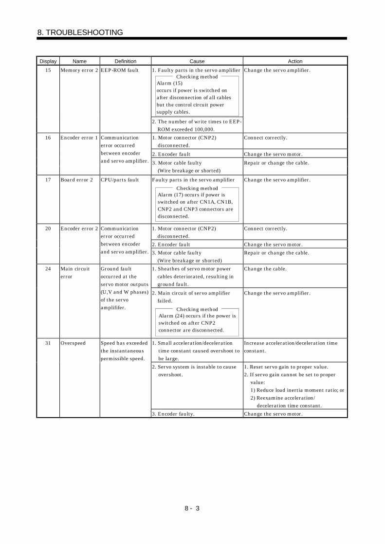
8 - 3
8. TROUBLESHOOTING
Display Name Definition Cause Action1. Faulty parts in the servo amplifier
Checking methodAlarm (15) occurs if power is switched onafter disconnection of all cables but the control circuit power supply cables.
15 Memory error 2 EEP-ROM fault
2. The number of write times to EEP-ROM exceeded 100,000.
Change the servo amplifier.
1. Motor connector (CNP2)disconnected.
Connect correctly.
2. Encoder fault Change the servo motor.
16 Encoder error 1 Communicationerror occurredbetween encoderand servo amplifier. 3. Motor cable faulty
(Wire breakage or shorted)Repair or change the cable.
17 Board error 2 CPU/parts fault Faulty parts in the servo amplifierChecking method
Alarm (17) occurs if power isswitched on after CN1A, CN1B,CNP2 and CNP3 connectors aredisconnected.
Change the servo amplifier.
1. Motor connector (CNP2)disconnected.
Connect correctly.
2. Encoder fault Change the servo motor.
20 Encoder error 2 Communicationerror occurredbetween encoderand servo amplifier. 3. Motor cable faulty
(Wire breakage or shorted)Repair or change the cable.
1. Sheathes of servo motor powercables deteriorated, resulting inground fault.
Change the cable.24 Main circuiterror
Ground faultoccurred at theservo motor outputs(U,V and W phases)of the servoamplififer.
2. Main circuit of servo amplifierfailed.
Checking methodAlarm (24) occurs if the power isswitched on after CNP2connector are disconnected.
Change the servo amplifier.
1. Small acceleration/decelerationtime constant caused overshoot tobe large.
Increase acceleration/deceleration timeconstant.
2. Servo system is instable to causeovershoot.
1. Reset servo gain to proper value.2. If servo gain cannot be set to proper
value:1) Reduce load inertia moment ratio; or2) Reexamine acceleration/
deceleration time constant.
31 Overspeed Speed has exceededthe instantaneouspermissible speed.
3. Encoder faulty. Change the servo motor.
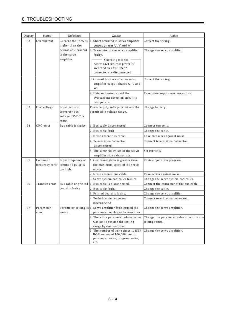
8 - 4
8. TROUBLESHOOTING
Display Name Definition Cause Action1. Short occurred in servo amplifier
output phases U, V and W.Correct the wiring.
2. Transistor of the servo amplifierfaulty.
Checking methodAlarm (32) occurs if power isswitched on after CNP2connector are disconnected.
Change the servo amplifier.
3. Ground fault occurred in servoamplifier output phases U, V andW.
Correct the wiring.
32 Overcurrent Current that flew ishigher than thepermissible currentof the servoamplifier.
4. External noise caused theovercurrent detection circuit tomisoperate.
Take noise suppression measures.
33 Overvoltage Input value ofconverter busvoltage 35VDC ormore.
Power supply voltage is outside thepermissible voltage range.
Change battery.
1. Bus cable disconnected. Connect correctly.2. Bus cable fault Change the cable.3. Noise entere bus cable. Take measures against noise.4. Termination connector
disconnected.Connect termination connector.
34 CRC error Bus cable is faulty
5. The same No. exists in the servoamplifier side axis setting.
Set correctly.
1. Command given is greater thanthe maximum speed of the servomotor.
Review operation program.
2. Noise entered bus cable. Take action against noise.
35 Commandfrequency error
Input frequency ofcommand pulse istoo high.
3. Servo system controller failure Change the servo system controller.1. Bus cable is disconnected. Connect the connector of the bus cable.2. Bus cable fault. Change the cable.3. Printed board is faulty. Change the servo amplifier
36 Transfer error Bus cable or printedboard is faulty
4. Terimination connectordisconnected
Connect termination connector.
1. Servo amplifier fault caused theparameter setting to be rewritten.
Change the servo amplifier.
2. There is a parameter whose valuewas set to outside the settingrange by the controller.
Change the parameter value to within thesetting range.
37 Parametererror
Parameter setting iswrong.
3. The number of write times to EEP-ROM exceeded 100,000 due toparameter write, program write,etc.
Change the servo amplifier.
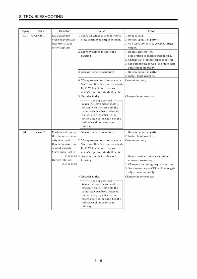
8 - 5
8. TROUBLESHOOTING
Display Name Definition Cause Action1. Servo amplifier is used in excess
of its continuous output current.1. Reduce load.2. Review operation pattern.3. Use servo motor that provides larger
output.2. Servo system is instable and
hunting.1. Repeat acceleration/
deceleration to execute auto tuning.2. Change auto tuning response setting.3. Set auto tuning to OFF and make gain
adjustment manually.3. Machine struck something. 1. Review operation pattern.
2. Install limit switches.4. Wrong connection of servo motor.
Servo amplifier's output terminalsU, V, W do not match servomotor's input terminals U, V, W.
Connect correctly.
50 Overload 1 Load exceededoverload protectioncharacteristic ofservo amplifier.
5. Encoder faulty.Checking method
When the servo motor shaft isrotated with the servo off, thecumulative feedback pulses donot vary in proportion to therotary angle of the shaft but theindication skips or returnsmidway.
Change the servo motor.
1. Machine struck something. 1. Review operation pattern.2. Install limit switches.
2. Wrong connection of servo motor.Servo amplifier's output terminalsU, V, W do not match servomotor's input terminals U, V, W.
Connect correctly.
3. Servo system is instable andhunting.
1. Repeat acceleration/deceleration toexecute auto tuning.
2. Change auto tuning response setting.3. Set auto tuning to OFF and make gain
adjustment manually.
51 Overload 2 Machine collision orthe like caused max.output current toflow successively forseveral seconds.Servo motor locked:
1s or moreDuring rotation:
2.5s or more
4. Encoder faulty.Checking method
When the servo motor shaft isrotated with the servo off, thecumulative feedback pulses donot vary in proportion to therotary angle of the shaft but theindication skips or returnsmidway.
Change the servo motor.
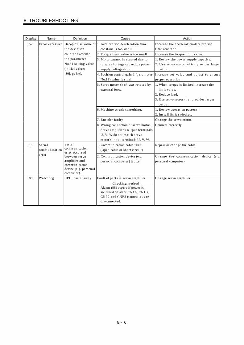
8 - 6
8. TROUBLESHOOTING
Display Name Definition Cause Action1. Acceleration/deceleration time
constant is too small.Increase the acceleration/decelerationtime constant.
2. Torque limit value is too small. Increase the torque limit value.3. Motor cannot be started due to
torque shortage caused by powersupply voltage drop.
1. Review the power supply capacity.2. Use servo motor which provides larger
output.4. Position control gain 1 (parameter
No.13) value is small.Increase set value and adjust to ensureproper operation.
5. Servo motor shaft was rotated byexternal force.
1. When torque is limited, increase thelimit value.
2. Reduce load.3. Use servo motor that provides larger
output.6. Machine struck something. 1. Review operation pattern.
2. Install limit switches.7. Encoder faulty Change the servo motor.
52 Error excessive Droop pulse value ofthe deviationcounter exceededthe parameterNo.31 setting value(initial value: 80k pulse).
8. Wrong connection of servo motor.Servo amplifier's output terminalsU, V, W do not match servomotor's input terminals U, V, W.
Connect correctly.
1. Communication cable fault(Open cable or short circuit)
Repair or change the cable.8E Serialcommunicationerror
Serialcommunicationerror occurredbetween servoamplifier andcommunicationdevice (e.g. personalcomputer).
2. Communication device (e.g.personal computer) faulty
Change the communication device (e.g.personal computer).
88 Watchdog CPU, parts faulty Fault of parts in servo amplifierChecking method
Alarm (88) occurs if power is switched on after CN1A, CN1B,CNP2 and CNP3 connectors aredisconnected.
Change servo amplifier.
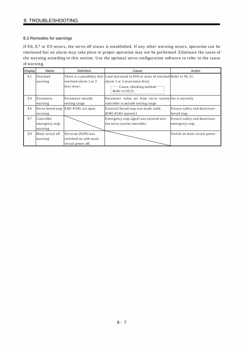
8 - 7
8. TROUBLESHOOTING
8.3 Remedies for warnings
If E6, E7 or E9 occurs, the servo off status is established. If any other warning occurs, operation can becontinued but an alarm may take place or proper operation may not be performed. Eliminate the cause ofthe warning according to this section. Use the optional servo configuration software to refer to the causeof warning.Display Name Definition Cause Action
E1 Overloadwarning
There is a possibility thatoverload alarm 1 or 2may occur.
Load increased to 85% or more of overloadalarm 1 or 2 occurrence level.
Cause, checking methodRefer to 50,51.
Refer to 50, 51.
E4 Parameterwarning
Parameter outsidesetting range
Parameter value set from servo systemcontroller is outside setting range
Set it correctly.
E6 Servo forced stopwarning
EM1-P24G are open. External forced stop was made valid.(EM1-P24G opened.)
Ensure safety and deactivateforced stop.
E7 Controlleremergency stopwarning
Emergency stop signal was entered intothe servo system controller.
Ensure safety and deactivateemergency stop.
E9 Main circuit offwarning
Servo-on (SON) wasswitched on with maincircuit power off.
Switch on main circuit power.

8 - 8
8. TROUBLESHOOTING
MEMO
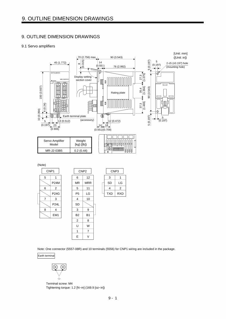
9 - 1
9. OUTLINE DIMENSION DRAWINGS
9. OUTLINE DIMENSION DRAWINGS
9.1 Servo amplifiers
5 (0
.197
)
5(0.197)
5
5 (0
.197
)
2- 5 ( 0.197) hole
Servo AmplifierModel
Weight[kg] ([lb])
MR-J2-03B5 0.2 (0.44)90
(3.5
43)
B2 B1
5 1
P24M
6 2
P24G
7 3
P24L
8 4
EM1
5
1
MR MRR
6
2
P5 LG
11
12
SD
104
7
3
U W
8
9
E V
1
SD
2
TXD
LG
3
RXD
4
CNP1 CNP2 CNP3
Earth terminal
(0.197)
27.3
90 (3.543)70 (2.756) max.
76 (2.992)
35.4
37.3
1814
8
MITSUBISHI
OPENCN1A CN1B
CNP1 CNP2
CNP3
MELSERVO
45 (1.772)
5
6 (0
.24)
10 (0
.394
)10
0 (3
.937
)
23(0.197)(0.906) (0.551)(0.709)
(1.0
75)
(1.3
94)
(1.4
69)
12 (0.472)13 (0.512)
14(0.551)(0
.315
)
Earth terminal plate(accessory)
Display settingsection cover
Rating plate
(mounting hole)
(Note)
Note: One connector (5557-08R) and 10 terminals (5556) for CNP1 wiring are included in the package.
[Unit: mm]([Unit: in])
Terminal screw: M4Tightening torque: 1.2 [N m] (169.9 [oz in])
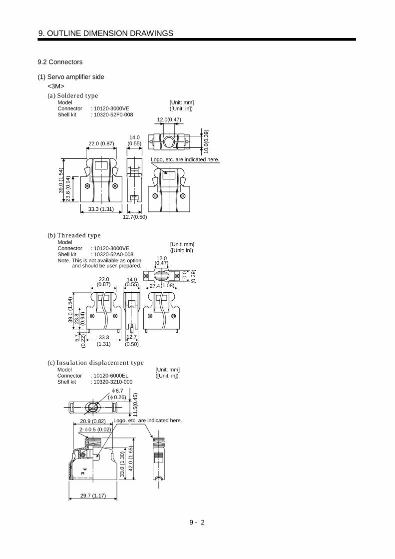
9 - 2
9. OUTLINE DIMENSION DRAWINGS
9.2 Connectors
(1) Servo amplifier side<3M>(a) Soldered type
Model Connector : 10120-3000VE Shell kit : 10320-52F0-008
[Unit: mm] ([Unit: in])
10.0
(0.3
9)
Logo, etc. are indicated here.
12.0(0.47)
22.0 (0.87)
39.0
(1.5
4)23
.8 (0
.94)
14.0 (0.55)
12.7(0.50)33.3 (1.31)
(b) Threaded type[Unit: mm] ([Unit: in])
10.0
12.0
22.0
39.0
23.8
14.0
12.733.35.7
27.4
(1.31) (0.50)(0.2
2)(0
.94)
(1.5
4)
(0.3
9)
(0.87) (0.55) (1.08)
(0.47)
Model Connector : 10120-3000VE Shell kit : 10320-52A0-008Note. This is not available as option
and should be user-prepared.
(c) Insulation displacement typeModelConnector : 10120-6000EL Shell kit : 10320-3210-000
[Unit: mm] ([Unit: in])
42.0
(1.6
5)11
.5(0
.45)
6.7( 0.26)
20.9 (0.82)2- 0.5 (0.02)
29.7 (1.17)
Logo, etc. are indicated here.
33.0
(1.3
0)
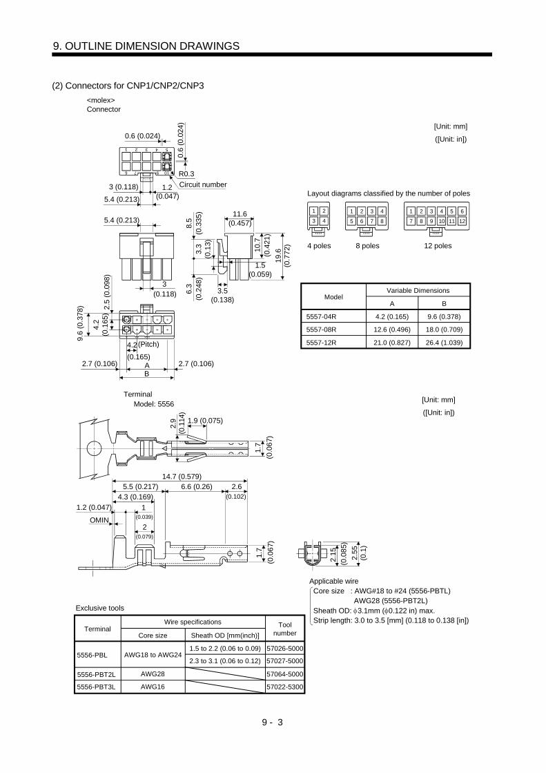
9 - 3
9. OUTLINE DIMENSION DRAWINGS
(2) Connectors for CNP1/CNP2/CNP3
11.6
3.5(0.138)
3
9.6
(0.3
78)
2.7 (0.106) AB
4.2
4.2
(0.1
65)
2.5
(0.0
98)
8.5
6.3
3.3
(0.1
3)
10.7
19.6
1 2 3 4 5
6 7 9 10
0.6 (0.024)
0.6
(0.0
24)
R0.3
1.25.4 (0.213)
1 2 3 4 5 6
7 9 118 10 12
2 3 4
5 76 8
1 2
3 4
ModelVariable Dimensions
A
9.6 (0.378)5557-04R
5557-08R
5557-12R
4.2 (0.165)
18.0 (0.709)12.6 (0.496)
26.4 (1.039)21.0 (0.827)
B
1
(0.047)
5.4 (0.213)
3 (0.118)(0
.335
)(0
.248
)
(0.4
21)
(0.7
72)
(0.457)
(0.118)
2.7 (0.106)(0.165)
[Unit: mm]
([Unit: in])
1.5(0.059)
Connector<molex>
Circuit number
(Pitch)
Layout diagrams classified by the number of poles
4 poles 8 poles 12 poles
2.15
2.9 1.9 (0.075)
1.7
2.551.7
2.6
1
6.6 (0.26)14.7 (0.579)
5.5 (0.217)4.3 (0.169)
2
(0.1
14)
(0.0
67)
(0.102)
(0.079)
(0.039)
(0.0
67)
(0.1
)
(0.0
85)
Applicable wire Core size : AWG#18 to #24 (5556-PBTL) AWG28 (5556-PBT2L) Sheath OD: 3.1mm ( 0.122 in) max. Strip length: 3.0 to 3.5 [mm] (0.118 to 0.138 [in])
Terminal Model: 5556
OMIN
1.2 (0.047)
[Unit: mm]
([Unit: in])
TerminalWire specifications
Core size
1.5 to 2.2 (0.06 to 0.09)5556-PBL
5556-PBT2L
AWG18 to AWG242.3 to 3.1 (0.06 to 0.12)
AWG28
Sheath OD [mm(inch)]
Exclusive tools
57026-5000
57027-5000
57064-5000
Toolnumber
5556-PBT3L AWG16 57022-5300
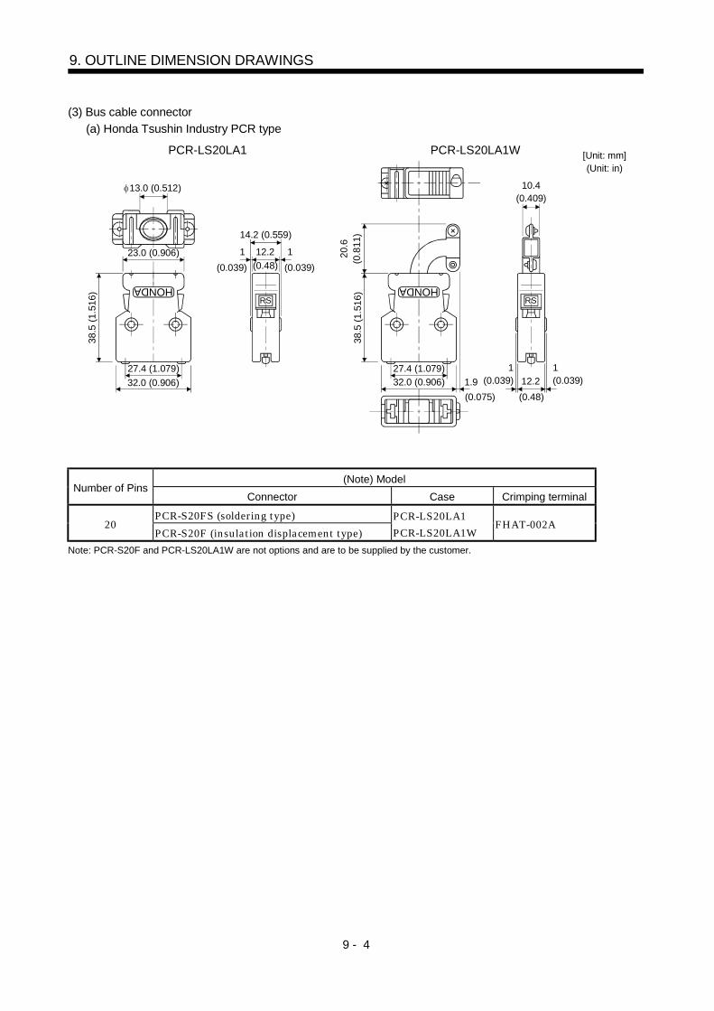
9 - 4
9. OUTLINE DIMENSION DRAWINGS
(3) Bus cable connector(a) Honda Tsushin Industry PCR type
38.5
(1.5
16)
27.4 (1.079)32.0 (0.906)
HONDA
13.0 (0.512)
1 12.2
14.2 (0.559)
38.5
(1.5
16)
27.4 (1.079)32.0 (0.906)
HONDA
10.4(0.409)
1.9
20.6
(0.8
11)
12.2
PCR-LS20LA1WPCR-LS20LA1 [Unit: mm](Unit: in)
23.0 (0.906)(0.039)
1(0.039)
(0.075)
1(0.039)
1(0.039)
(0.48)
(0.48)
RS RS
(Note) ModelNumber of Pins
Connector Case Crimping terminal
PCR-S20FS (soldering type)20
PCR-S20F (insulation displacement type)PCR-LS20LA1PCR-LS20LA1W
FHAT-002A
Note: PCR-S20F and PCR-LS20LA1W are not options and are to be supplied by the customer.
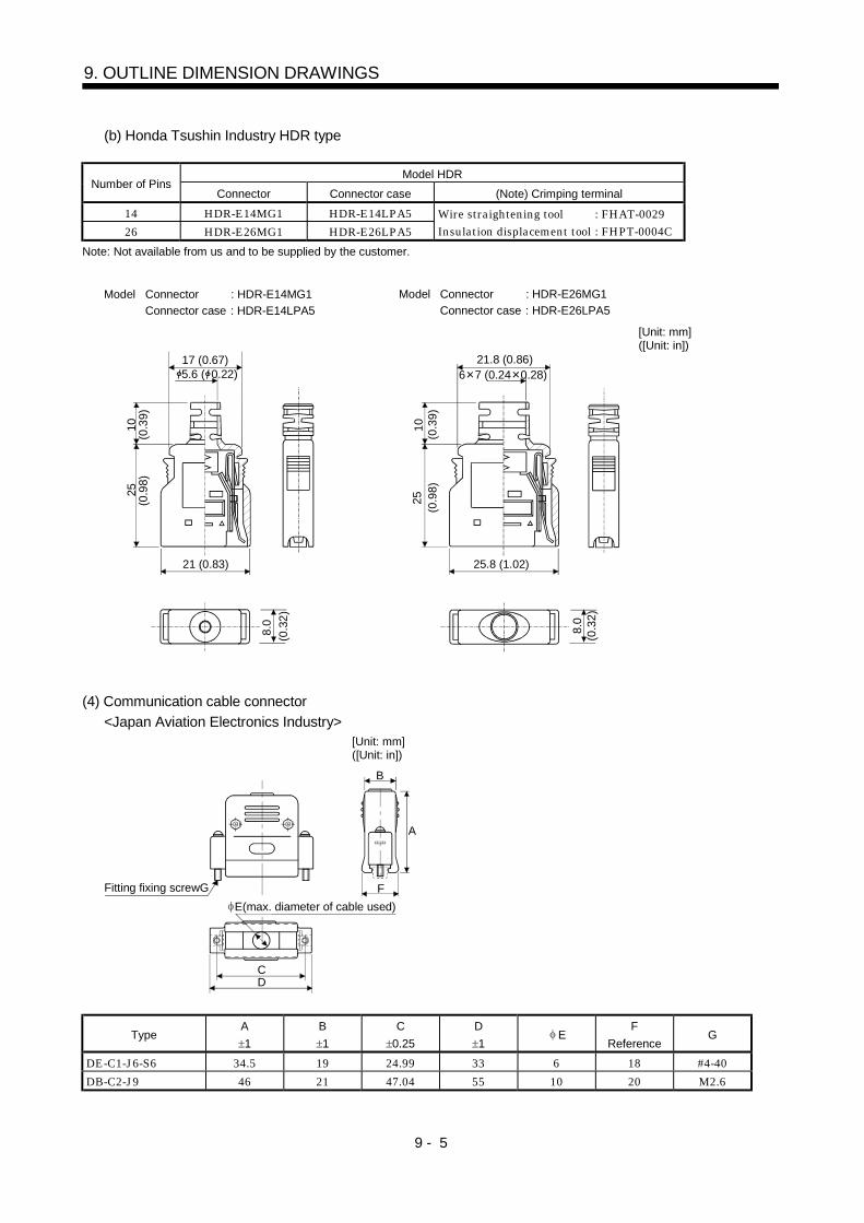
9 - 5
9. OUTLINE DIMENSION DRAWINGS
(b) Honda Tsushin Industry HDR type
Model HDRNumber of Pins
Connector Connector case (Note) Crimping terminal14 HDR-E14MG1 HDR-E14LPA526 HDR-E26MG1 HDR-E26LPA5
Wire straightening tool : FHAT-0029Insulation displacement tool : FHPT-0004C
Note: Not available from us and to be supplied by the customer.
21 (0.83)
17 (0.67)5.6 ( 0.22)
2510
8.0
(0.3
9)(0
.98)
(0.3
2)Model Connector : HDR-E14MG1
Connector case : HDR-E14LPA5
25.8 (1.02)
21.8 (0.86)
2510
8.0
6 7 (0.24 0.28)
(0.3
9)(0
.98)
(0.3
2)
Model Connector : HDR-E26MG1Connector case : HDR-E26LPA5
[Unit: mm] ([Unit: in])
(4) Communication cable connector<Japan Aviation Electronics Industry>
CD
Fitting fixing screwGE(max. diameter of cable used)
F
A
B
[Unit: mm] ([Unit: in])
TypeA1
B1
C0.25
D1
EF
ReferenceG
DE-C1-J6-S6 34.5 19 24.99 33 6 18 #4-40DB-C2-J9 46 21 47.04 55 10 20 M2.6

9 - 6
9. OUTLINE DIMENSION DRAWINGS
MEMO
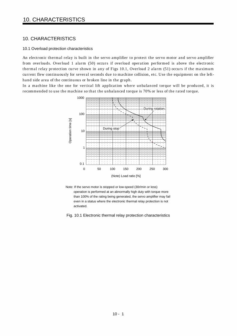
10 - 1
10. CHARACTERISTICS
10. CHARACTERISTICS
10.1 Overload protection characteristics
An electronic thermal relay is built in the servo amplifier to protect the servo motor and servo amplifierfrom overloads. Overload 1 alarm (50) occurs if overload operation performed is above the electronicthermal relay protection curve shown in any of Figs 10.1, Overload 2 alarm (51) occurs if the maximumcurrent flew continuously for several seconds due to machine collision, etc. Use the equipment on the left-hand side area of the continuous or broken line in the graph.In a machine like the one for vertical lift application where unbalanced torque will be produced, it isrecommended to use the machine so that the unbalanced torque is 70% or less of the rated torque.
1000
100
10
1
0.10 50 150 200 250 300
(Note) Load ratio [%]
100
Ope
ratio
n tim
e [s
]
During stop
During rotation
Note: If the servo motor is stopped or low-speed (30r/min or less)operation is performed at an abnormally high duty with torque morethan 100% of the rating being generated, the servo amplifier may faileven in a status where the electronic thermal relay protection is notactivated.
Fig. 10.1 Electronic thermal relay protection characteristics
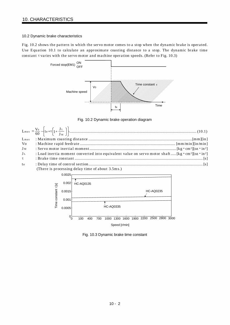
10 - 2
10. CHARACTERISTICS
10.2 Dynamic brake characteristics
Fig. 10.2 shows the pattern in which the servo motor comes to a stop when the dynamic brake is operated.Use Equation 10.1 to calculate an approximate coasting distance to a stop. The dynamic brake timeconstant varies with the servo motor and machine operation speeds. (Refer to Fig. 10.3)
V0Time constant
Forced stop(EM1) OFFON
Machine speed
te Time
Fig. 10.2 Dynamic brake operation diagram
Lmax 60V0 JL
JMte 1 ....................................................................................................................... (10.1)
Lmax : Maximum coasting distance .................................................................................................[mm][in]Vo : Machine rapid feedrate ......................................................................................... [mm/min][in/min]JM : Servo motor inertial moment................................................................................. [kg cm2][oz in2]JL : Load inertia moment converted into equivalent value on servo motor shaft..... [kg cm2][oz in2]
: Brake time constant ........................................................................................................................ [s]te : Delay time of control section........................................................................................................... [s]
(There is processing delay time of about 3.5ms.)
0
0.0005
0.001
0.0015
0.002
0.0025
0 100 400 700 1000 1300 1600
HC-AQ0135
HC-AQ0335
1900 2200 2500 2800 3000
HC-AQ0235
Tim
e co
nsta
nt
[s]
Speed [r/min]
Fig. 10.3 Dynamic brake time constant
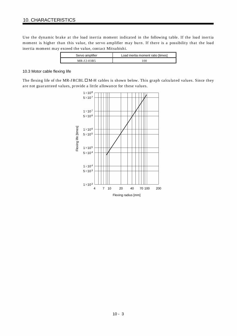
10 - 3
10. CHARACTERISTICS
Use the dynamic brake at the load inertia moment indicated in the following table. If the load inertiamoment is higher than this value, the servo amplifier may burn. If there is a possibility that the loadinertia moment may exceed the value, contact Mitsubishi.
Servo amplifier Load inertia moment ratio [times]MR-J2-03B5 100
10.3 Motor cable flexing life
The flexing life of the MR-JRCBL M-H cables is shown below. This graph calculated values. Since theyare not guaranteed values, provide a little allowance for these values.
1 108
4 7 10 20 40 70 100 200
Flex
ing
life
[tim
es]
Flexing radius [mm]
1 107
1 106
1 105
5 10 4
5 10 3
5 10 7
5 10 6
5 105
1 104
1 103

10 - 4
10. CHARACTERISTICS
MEMO
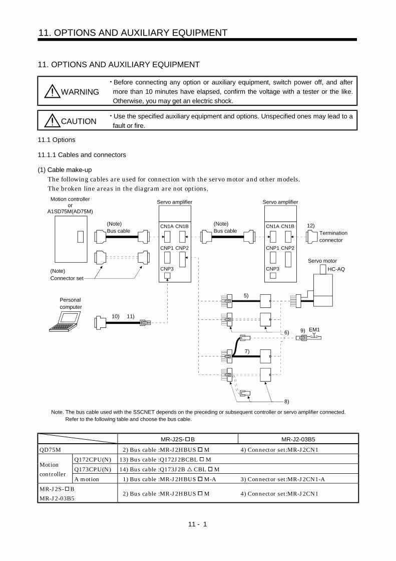
11 - 1
11. OPTIONS AND AUXILIARY EQUIPMENT
11. OPTIONS AND AUXILIARY EQUIPMENT
WARNINGBefore connecting any option or auxiliary equipment, switch power off, and aftermore than 10 minutes have elapsed, confirm the voltage with a tester or the like.Otherwise, you may get an electric shock.
CAUTIONUse the specified auxiliary equipment and options. Unspecified ones may lead to afault or fire.
11.1 Options
11.1.1 Cables and connectors
(1) Cable make-upThe following cables are used for connection with the servo motor and other models.The broken line areas in the diagram are not options.Motion controller
orA1SD75M(AD75M)
(Note)Bus cable
CNP3
CN1A CN1B
CNP1 CNP2
CNP3
CN1A CN1B
CNP1 CNP2
Servo amplifier
(Note)Bus cable
Servo amplifier
12)Terminationconnector
Servo motorHC-AQ
5)
EM1 6) 9)
7)
8)
(Note)Connector set
Personalcomputer
10) 11)
Note. The bus cable used with the SSCNET depends on the preceding or subsequent controller or servo amplifier connected. Refer to the following table and choose the bus cable.
MR-J2S- B MR-J2-03B5
QD75M 2) Bus cable :MR-J2HBUS M 4) Connector set:MR-J2CN1Q172CPU(N) 13) Bus cable :Q172J2BCBL MQ173CPU(N) 14) Bus cable :Q173J2B CBL M
Motioncontroller
A motion 1) Bus cable :MR-J2HBUS M-A 3) Connector set:MR-J2CN1-AMR-J2S- BMR-J2-03B5
2) Bus cable :MR-J2HBUS M 4) Connector set:MR-J2CN1
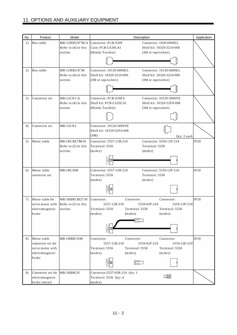
11 - 2
11. OPTIONS AND AUXILIARY EQUIPMENT
No. Product Model Description ApplicationConnector: PCR-S20FCase: PCR-LS20LA1(Honda Tsushin)
Connector: 1020-6000ELShell kit: 10320-3210-000(3M or equivalent)
1) Bus cable MR-J2HBUS M-ARefer to (4) in thissection.
Connector: 10120-6000ELShell kit: 10320-3210-000(3M or equivalent)
Connector: 10120-6000ELShell kit: 10320-3210-000(3M or equivalent)
2) Bus cable MR-J2HBUS MRefer to (4) in thissection.
Connector: PCR-S20FSShell kit: PCR-LS20LA1(Honda Tsushin)
Connector: 10120-3000VEShell kit: 10320-52F0-008(3M or equivalent)
3) Connector set MR-J2CN1-ARefer to (4) in thissection
4) Connector set MR-J2CN1 Connector: 10120-3000VEShell kit: 10320-52F0-008(3M) Qty: 2 eachConnector: 5557-12R-210Terminal: 5556(molex)
Connector: 5559-12P-210Terminal: 5558(molex)
5) Motor cable MR-JRCBL M-HRefer to (2) in thissection.
IP20
Connector: 5557-12R-210Terminal: 5556(molex)
Connector: 5559-12P-210Terminal: 5558(molex)
6) Motor cableconnector set
MR-JRCNM IP20
Connector:5557-12R-210
Terminal: 5556(molex)
Connector:5559-02P-210
Terminal: 5558(molex)
Connector:5559-12P-210
Terminal: 5558(molex)
7) Motor cable forservo motor withelectromagneticbrake
MR-JRBRCBL -HRefer to (2) in thissection.
IP20
Connector:5557-12R-210
Terminal: 5556(molex)
Connector:5559-02P-210
Terminal: 5558(molex)
Connector:5559-12P-210
Terminal: 5558(molex)
8) Motor cableconnector set forservo motor withelectromagneticbrake
MR-JRBRCNM IP20
9) Connector set forelectromagneticbrake contact
MR-JRBRCN Connector:5557-02R-210 Qty: 1Terminal: 5556 Qty: 4(molex)
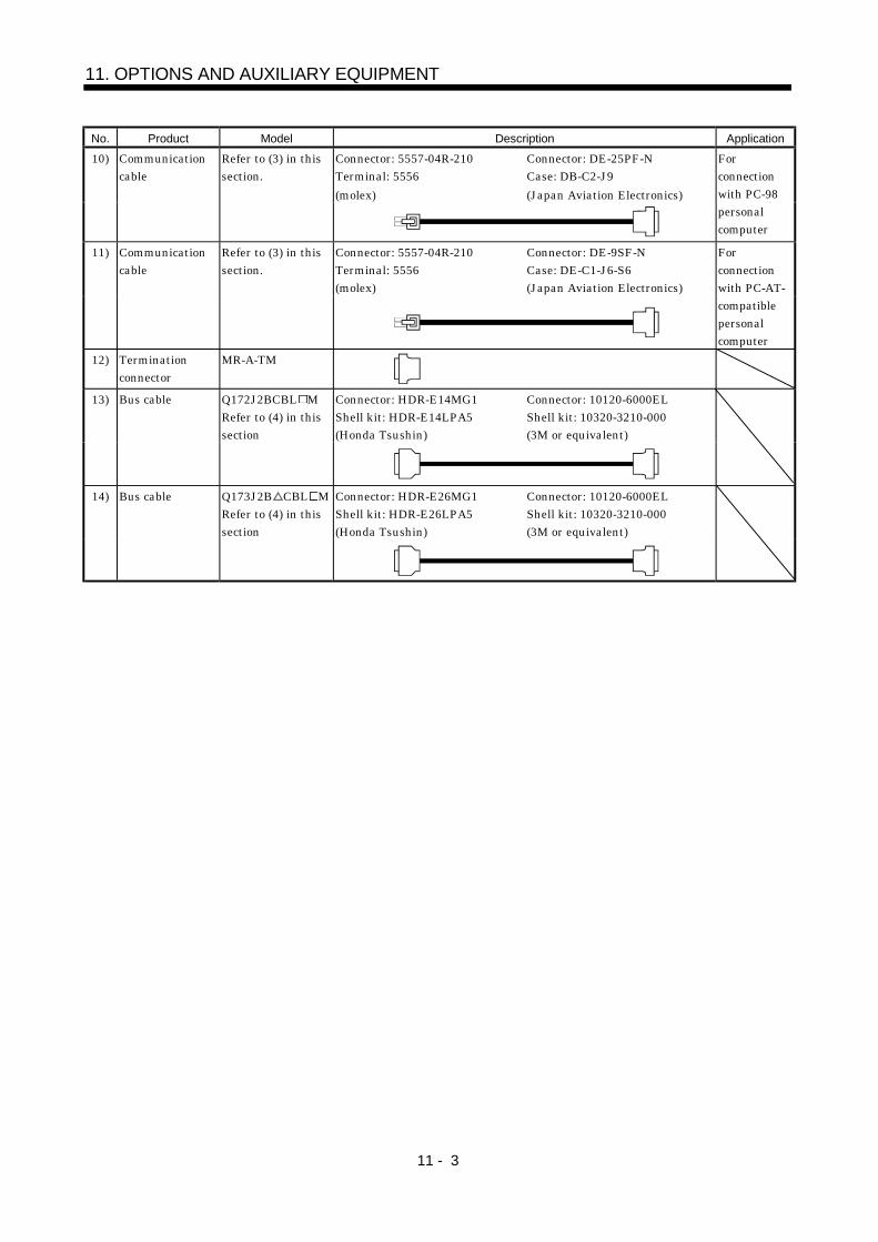
11 - 3
11. OPTIONS AND AUXILIARY EQUIPMENT
No. Product Model Description ApplicationConnector: 5557-04R-210Terminal: 5556(molex)
Connector: DE-25PF-NCase: DB-C2-J9(Japan Aviation Electronics)
10) Communicationcable
Refer to (3) in thissection.
Forconnectionwith PC-98personalcomputer
Connector: 5557-04R-210Terminal: 5556(molex)
Connector: DE-9SF-NCase: DE-C1-J6-S6(Japan Aviation Electronics)
11) Communicationcable
Refer to (3) in thissection.
Forconnectionwith PC-AT-compatiblepersonalcomputer
12) Terminationconnector
MR-A-TM
Connector: HDR-E14MG1Shell kit: HDR-E14LPA5(Honda Tsushin)
Connector: 10120-6000ELShell kit: 10320-3210-000(3M or equivalent)
13) Bus cable Q172J2BCBL MRefer to (4) in thissection
Connector: HDR-E26MG1Shell kit: HDR-E26LPA5(Honda Tsushin)
Connector: 10120-6000ELShell kit: 10320-3210-000(3M or equivalent)
14) Bus cable Q173J2B CBL MRefer to (4) in thissection
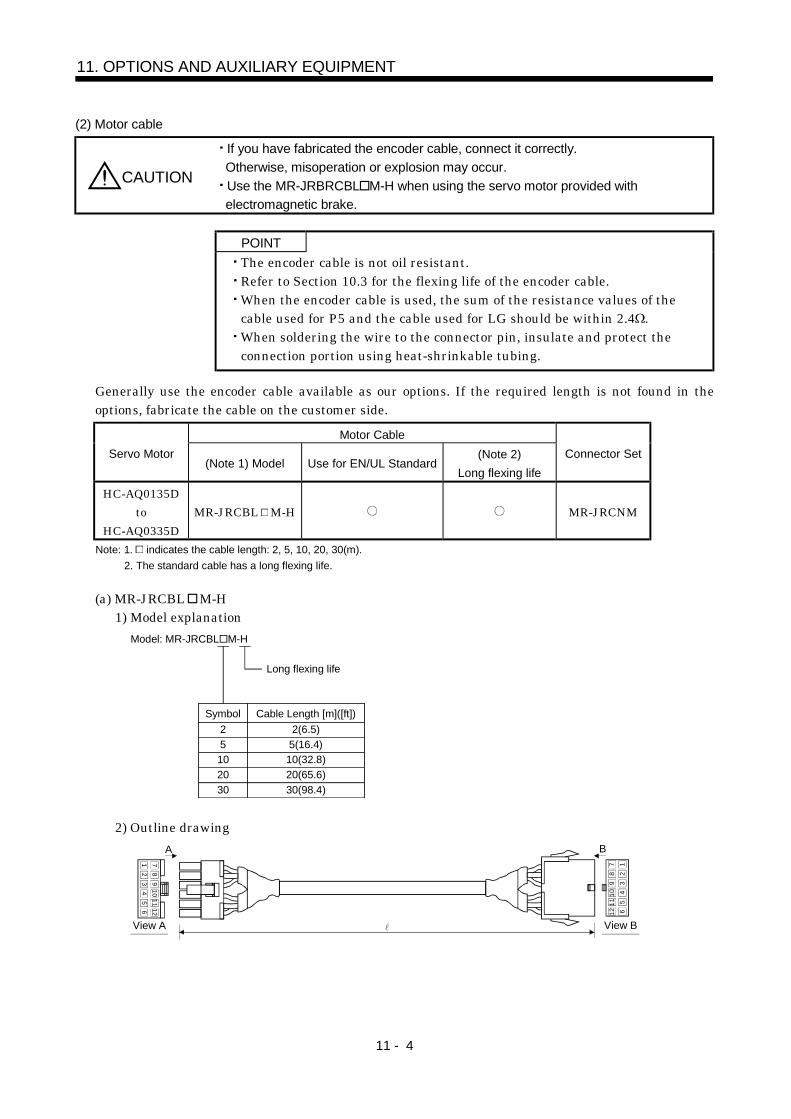
11 - 4
11. OPTIONS AND AUXILIARY EQUIPMENT
(2) Motor cable
CAUTION
If you have fabricated the encoder cable, connect it correctly.Otherwise, misoperation or explosion may occur.Use the MR-JRBRCBL M-H when using the servo motor provided withelectromagnetic brake.
POINTThe encoder cable is not oil resistant.Refer to Section 10.3 for the flexing life of the encoder cable.When the encoder cable is used, the sum of the resistance values of thecable used for P5 and the cable used for LG should be within 2.4 .When soldering the wire to the connector pin, insulate and protect theconnection portion using heat-shrinkable tubing.
Generally use the encoder cable available as our options. If the required length is not found in theoptions, fabricate the cable on the customer side.
Motor CableServo Motor
(Note 1) Model Use for EN/UL Standard(Note 2)
Long flexing lifeConnector Set
HC-AQ0135Dto
HC-AQ0335DMR-JRCBL M-H MR-JRCNM
Note: 1. indicates the cable length: 2, 5, 10, 20, 30(m).2. The standard cable has a long flexing life.
(a) MR-JRCBL M-H1) Model explanation
Model: MR-JRCBL M-H
25102030
2(6.5)5(16.4)10(32.8)20(65.6)30(98.4)
Long flexing life
Symbol Cable Length [m]([ft])
2) Outline drawing
12
34
56 12
1110
98
7 12
34
5612
1110
98
7
BA
View A View B
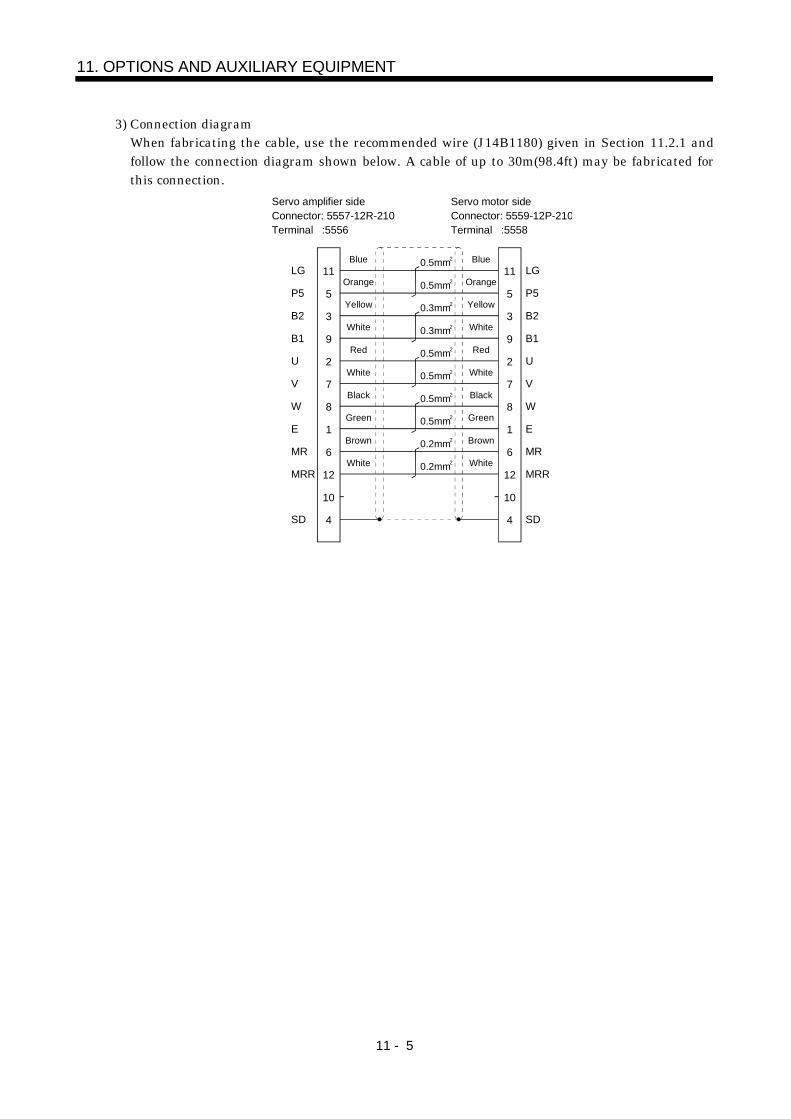
11 - 5
11. OPTIONS AND AUXILIARY EQUIPMENT
3) Connection diagramWhen fabricating the cable, use the recommended wire (J14B1180) given in Section 11.2.1 andfollow the connection diagram shown below. A cable of up to 30m(98.4ft) may be fabricated forthis connection.
11
5
3
9
2
7
8
1
6
12
10
4
11
5
3
9
2
7
8
1
6
12
10
4
LG
P5
B2
B1
U
V
W
E
MR
MRR
SD
LG
P5
B2
B1
U
V
W
E
SD
MR
MRR
0.5mm2
0.5mm2
0.3mm2
0.3mm2
0.5mm2
0.5mm2
0.5mm2
0.5mm2
0.2mm2
0.2mm2
Blue
Orange
Yellow
White
Red
White
Black
Green
Brown
White
Servo motor sideConnector: 5559-12P-210Terminal :5558
Servo amplifier sideConnector: 5557-12R-210Terminal :5556
Blue
Orange
Yellow
White
Red
White
Black
Green
Brown
White
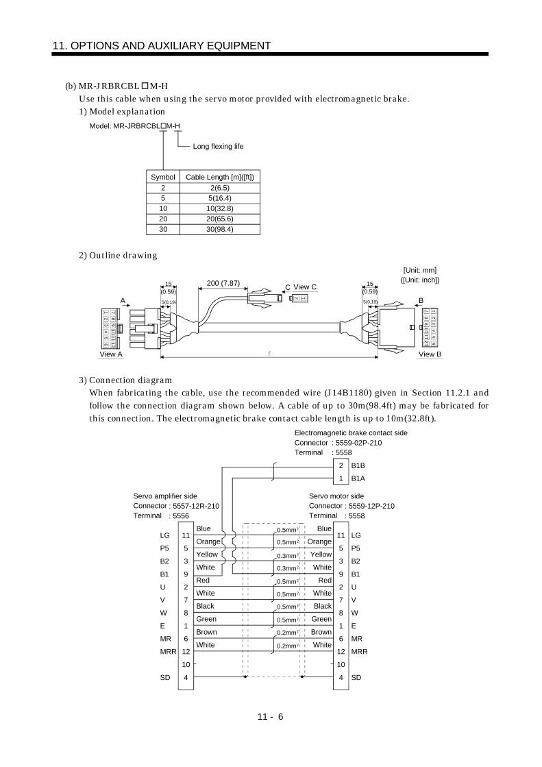
11 - 6
11. OPTIONS AND AUXILIARY EQUIPMENT
(b) MR-JRBRCBL M-HUse this cable when using the servo motor provided with electromagnetic brake.1) Model explanation
Model: MR-JRBRCBL M-H
25102030
2(6.5)5(16.4)
10(32.8)20(65.6)30(98.4)
Long flexing life
Symbol Cable Length [m]([ft])
2) Outline drawing
1211
65
109
43
87
21
1211
65
109
43
87
21
2 1
View A View B
A B
View C15(0.59) 5(0.19)
200 (7.87) 15(0.59) 5(0.19)
C
[Unit: mm]([Unit: inch])
3) Connection diagramWhen fabricating the cable, use the recommended wire (J14B1180) given in Section 11.2.1 andfollow the connection diagram shown below. A cable of up to 30m(98.4ft) may be fabricated forthis connection. The electromagnetic brake contact cable length is up to 10m(32.8ft).
11LG
5P5
3B2
9B1
2U
7V
8W
1E
6MR
12MRR
10
4SD
11
5
3
9
2
7
8
1
6
12
10
4
LG
P5
B2
B1
U
V
W
E
MR
MRR
SD
B1B
1 B1A
2
Blue
Orange
Yellow
White
Red
White
Black
Green
Brown
White
Blue
Orange
Yellow
White
Red
White
Black
Green
Brown
White
0.5mm 2
0.5mm 2
0.3mm 2
0.3mm 2
0.5mm 2
0.5mm 2
0.5mm 2
0.5mm 2
0.2mm 2
0.2mm 2
Servo motor sideConnectorTerminal
: 5559-12P-210: 5558
Servo amplifier sideConnectorTerminal
: 5557-12R-210: 5556
Electromagnetic brake contact sideConnectorTerminal
: 5559-02P-210: 5558
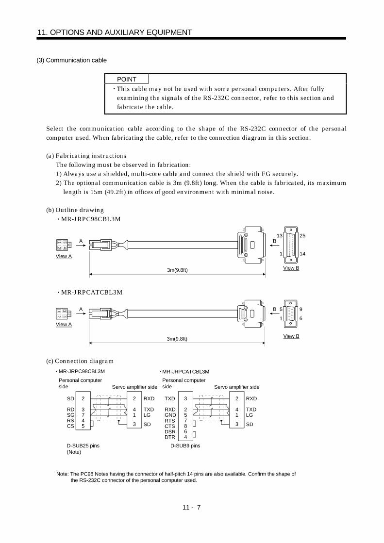
11 - 7
11. OPTIONS AND AUXILIARY EQUIPMENT
(3) Communication cable
POINTThis cable may not be used with some personal computers. After fullyexamining the signals of the RS-232C connector, refer to this section andfabricate the cable.
Select the communication cable according to the shape of the RS-232C connector of the personalcomputer used. When fabricating the cable, refer to the connection diagram in this section.
(a) Fabricating instructionsThe following must be observed in fabrication:1) Always use a shielded, multi-core cable and connect the shield with FG securely.2) The optional communication cable is 3m (9.8ft) long. When the cable is fabricated, its maximum
length is 15m (49.2ft) in offices of good environment with minimal noise.
(b) Outline drawingMR-JRPC98CBL3M
12
34
3m(9.8ft)
View A
A
View B
B13 25
141
MR-JRPCATCBL3M
12
34
3m(9.8ft)
View A
A
View B
B 5
1
9
6
(c) Connection diagram
2
3745
2
41
3
2
3
7
4
5
2
41
386
SD
RDSGRSCS
RXD
TXDLG
SD
RXD
TXDLG
SD
TXD
RXDGNDRTSCTSDSRDTR
D-SUB25 pins(Note)
D-SUB9 pins
Note: The PC98 Notes having the connector of half-pitch 14 pins are also available. Confirm the shape of the RS-232C connector of the personal computer used.
Servo amplifier side Servo amplifier side
MR-JRPC98CBL3M
Personal computerside
MR-JRPCATCBL3MPersonal computerside
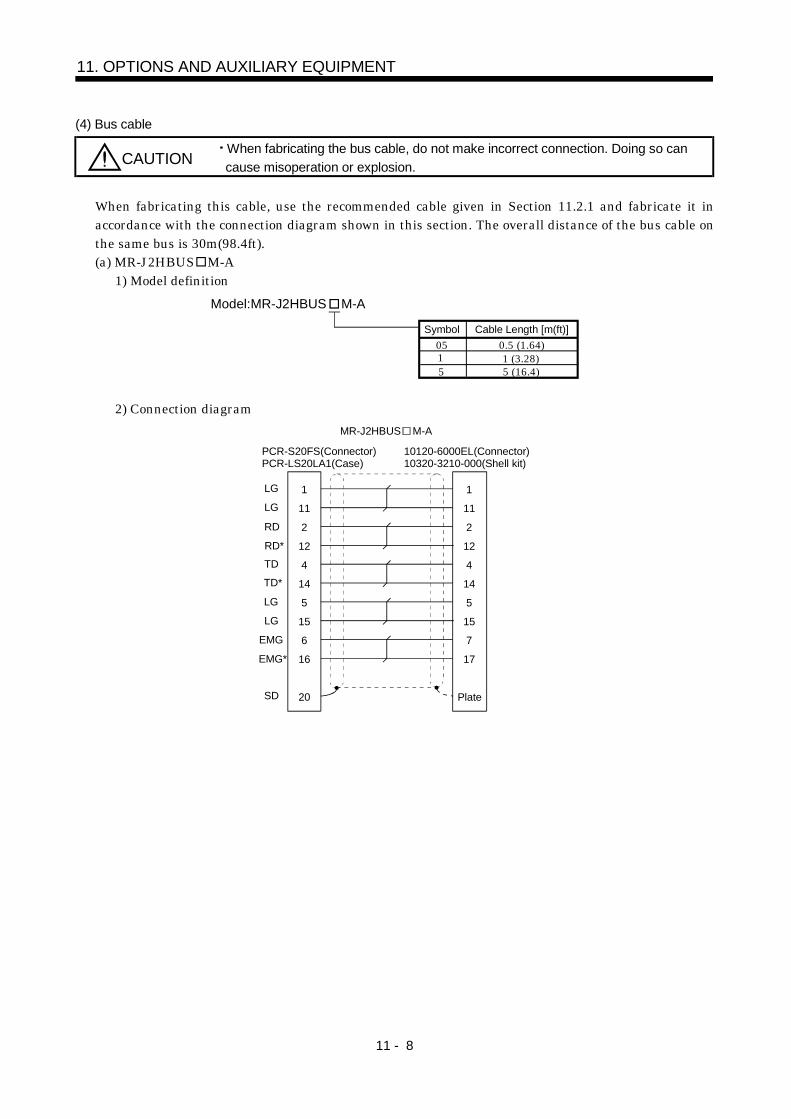
11 - 8
11. OPTIONS AND AUXILIARY EQUIPMENT
(4) Bus cable
CAUTIONWhen fabricating the bus cable, do not make incorrect connection. Doing so cancause misoperation or explosion.
When fabricating this cable, use the recommended cable given in Section 11.2.1 and fabricate it inaccordance with the connection diagram shown in this section. The overall distance of the bus cable onthe same bus is 30m(98.4ft).(a) MR-J2HBUS M-A
1) Model definitionModel:MR-J2HBUS M-A
05Cable Length [m(ft)]
5
Symbol0.5 (1.64)
5 (16.4)1 (3.28)1
2) Connection diagramMR-J2HBUS M-A
PCR-S20FS(Connector)PCR-LS20LA1(Case)
10120-6000EL(Connector)10320-3210-000(Shell kit)
SD
LG
LG
RD
RD*TD
TD*
LG
LG
EMG*
EMG
1
11
2
12
4
14
5
15
6
16
20 Plate
1
11
2
12
4
14
5
15
7
17
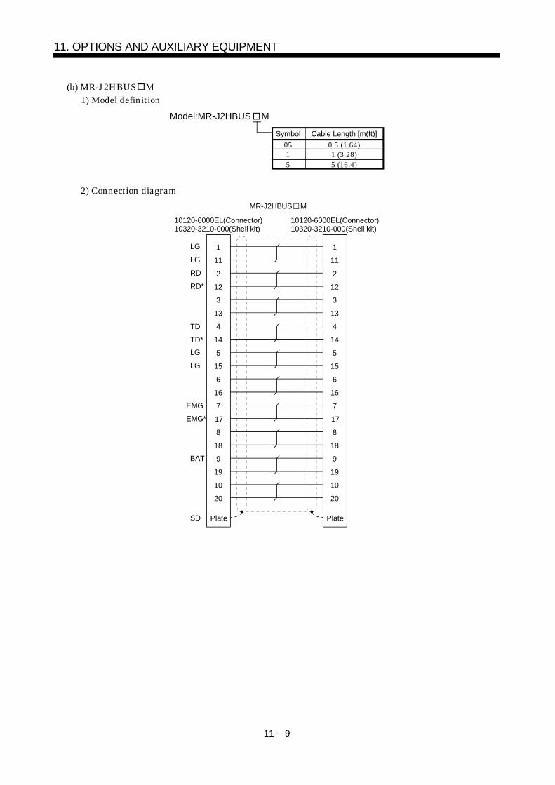
11 - 9
11. OPTIONS AND AUXILIARY EQUIPMENT
(b) MR-J2HBUS M1) Model definition
Model:MR-J2HBUS M
051
0.5 (1.64)1 (3.28)
5 5 (16.4)
Cable Length [m(ft)]Symbol
2) Connection diagramMR-J2HBUS M
10120-6000EL(Connector)10320-3210-000(Shell kit)
10120-6000EL(Connector)10320-3210-000(Shell kit)
1
11
2
12
3
13
4
14
5
15
Plate
6
16
7
17
8
18
9
19
10
20
1
11
2
12
3
13
4
14
5
15
Plate
6
16
7
17
8
18
9
19
10
20
LG
RD*
LG
RD
TD
TD*LG
LG
EMG
EMG*
BAT
SD
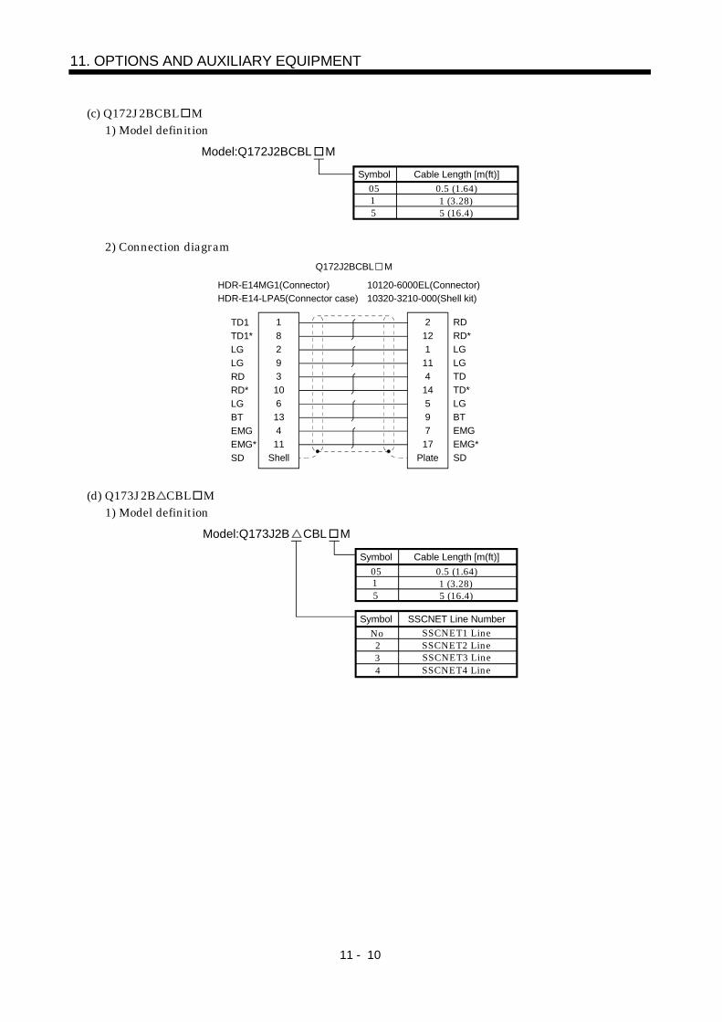
11 - 10
11. OPTIONS AND AUXILIARY EQUIPMENT
(c) Q172J2BCBL M1) Model definition
Model:Q172J2BCBL M
05Cable Length [m(ft)]
5
Symbol0.5 (1.64)
5 (16.4)1 (3.28)1
2) Connection diagram
HDR-E14MG1(Connector)HDR-E14-LPA5(Connector case)
10120-6000EL(Connector)10320-3210-000(Shell kit)
Shell
8293106134
TD1TD1*LGLGRDRD*LGBTEMGEMG*SD
1 RD
Plate
1211141459717
RD*LGLGTDTD*LGBTEMGEMG*SD
2
11
Q172J2BCBL M
(d) Q173J2B CBL M1) Model definition
05Cable Length [m(ft)]
5
Symbol0.5 (1.64)
5 (16.4)1 (3.28)1
Model:Q173J2B CBL M
NoSSCNET Line Number
3
SymbolSSCNET1 Line
SSCNET3 LineSSCNET2 Line2
SSCNET4 Line4
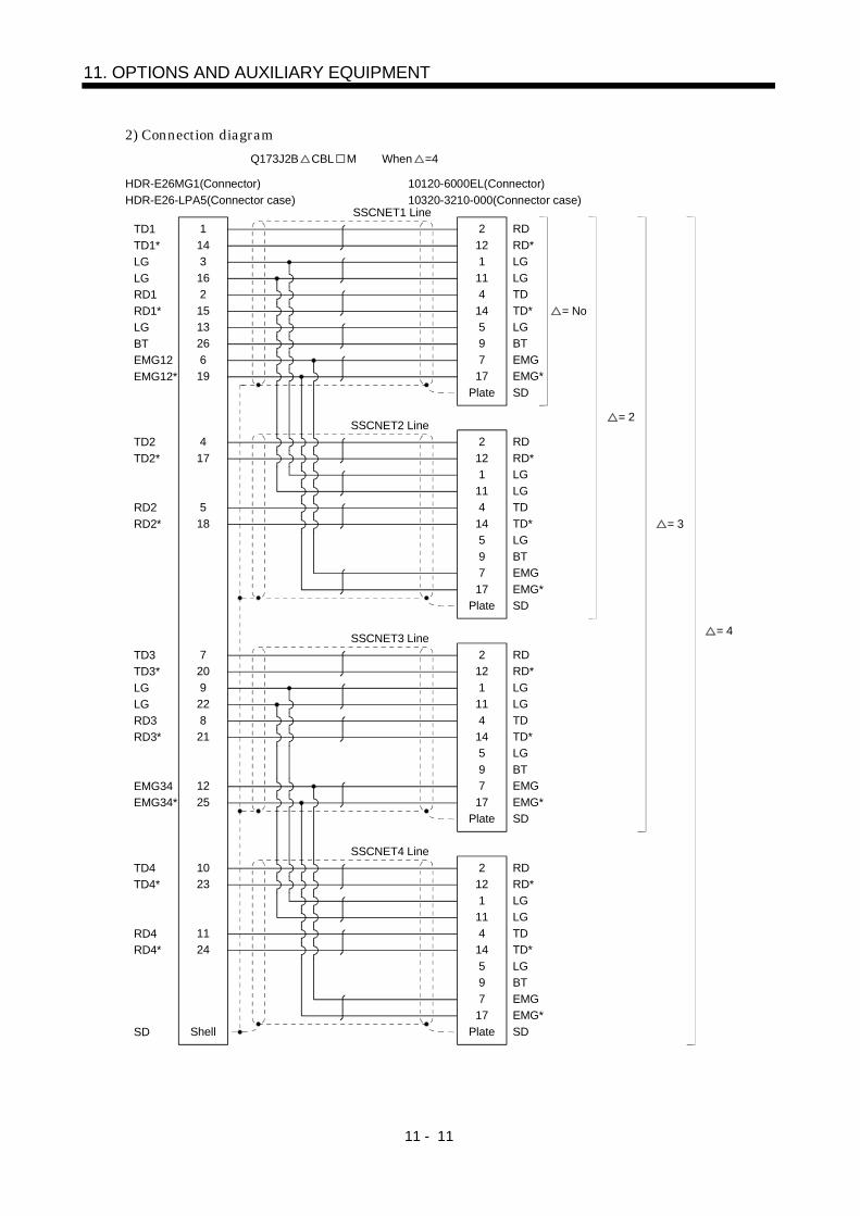
11 - 11
11. OPTIONS AND AUXILIARY EQUIPMENT
2) Connection diagram
HDR-E26MG1(Connector)HDR-E26-LPA5(Connector case)
10120-6000EL(Connector)10320-3210-000(Connector case)
1431621513266
TD1TD1*LGLGRD1RD1*LGBTEMG12EMG12*
1 RD
Plate
121
114
14597
17
RD*LGLGTDTD*LGBTEMGEMG*SD
2
19
RD
Plate
121
114
14597
17
RD*LGLGTDTD*LGBTEMGEMG*SD
2
RD
Plate
121
114
14597
17
RD*LGLGTDTD*LGBTEMGEMG*SD
2
RD
Plate
121
114
14597
17
RD*LGLGTDTD*LGBTEMGEMG*SD
2
17
518
TD2TD2*
RD2RD2*
4
20922821
12
TD3TD3*LGLGRD3RD3*
EMG34EMG34*
7
25
Shell
23
1124
TD4TD4*
RD4RD4*
SD
10
SSCNET1 Line
SSCNET2 Line
SSCNET3 Line
SSCNET4 Line
= No
= 2
= 3
= 4
Q173J2B CBL M When =4
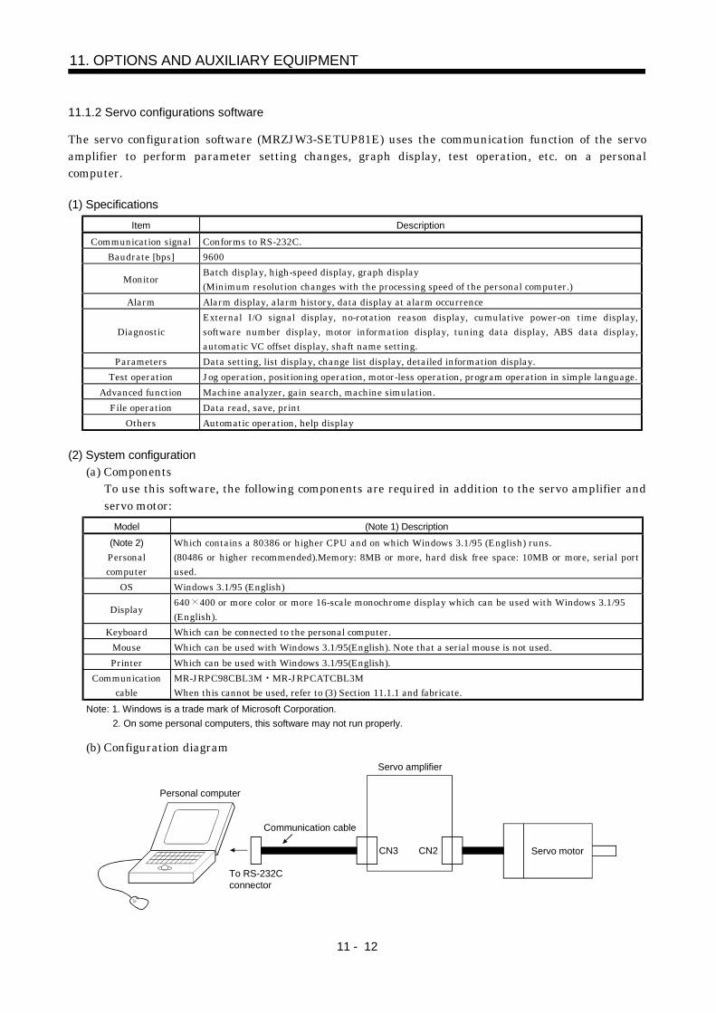
11 - 12
11. OPTIONS AND AUXILIARY EQUIPMENT
11.1.2 Servo configurations software
The servo configuration software (MRZJW3-SETUP81E) uses the communication function of the servoamplifier to perform parameter setting changes, graph display, test operation, etc. on a personalcomputer.
(1) SpecificationsItem Description
Communication signal Conforms to RS-232C.Baudrate [bps] 9600
Monitor Batch display, high-speed display, graph display(Minimum resolution changes with the processing speed of the personal computer.)
Alarm Alarm display, alarm history, data display at alarm occurrence
DiagnosticExternal I/O signal display, no-rotation reason display, cumulative power-on time display,software number display, motor information display, tuning data display, ABS data display,automatic VC offset display, shaft name setting.
Parameters Data setting, list display, change list display, detailed information display.Test operation Jog operation, positioning operation, motor-less operation, program operation in simple language.
Advanced function Machine analyzer, gain search, machine simulation.File operation Data read, save, print
Others Automatic operation, help display
(2) System configuration(a) Components
To use this software, the following components are required in addition to the servo amplifier andservo motor:
Model (Note 1) Description(Note 2)Personalcomputer
Which contains a 80386 or higher CPU and on which Windows 3.1/95 (English) runs.(80486 or higher recommended).Memory: 8MB or more, hard disk free space: 10MB or more, serial portused.
OS Windows 3.1/95 (English)
Display 640 400 or more color or more 16-scale monochrome display which can be used with Windows 3.1/95(English).
Keyboard Which can be connected to the personal computer.Mouse Which can be used with Windows 3.1/95(English). Note that a serial mouse is not used.Printer Which can be used with Windows 3.1/95(English).
Communicationcable
MR-JRPC98CBL3M MR-JRPCATCBL3MWhen this cannot be used, refer to (3) Section 11.1.1 and fabricate.
Note: 1. Windows is a trade mark of Microsoft Corporation.2. On some personal computers, this software may not run properly.
(b) Configuration diagram
CN3 CN2
Personal computer
To RS-232Cconnector
Communication cable
Servo amplifier
Servo motor
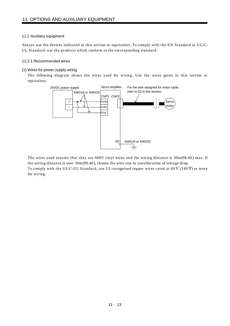
11 - 13
11. OPTIONS AND AUXILIARY EQUIPMENT
11.2 Auxiliary equipment
Always use the devices indicated in this section or equivalent. To comply with the EN Standard or UL/C-UL Standard, use the products which conform to the corresponding standard.
11.2.1 Recommended wires
(1) Wires for power supply wiringThe following diagram shows the wires used for wiring. Use the wires given in this section orequivalent.
Servo amplifier
CNP2CNP1
PE
24VDC power supplyAWG18 or AWG20
For the wire designed for motor cable,refer to (2) in this section.
AWG18 or AWG20
Servomotor
P24M
P24G
P24L
The wires used assume that they are 600V vinyl wires and the wiring distance is 30m(98.4ft) max. Ifthe wiring distance is over 30m(98.4ft), choose the wire size in consideration of voltage drop.To comply with the UL/C-UL Standard, use UL-recognized copper wires rated at 60 (140 ) or morefor wiring.
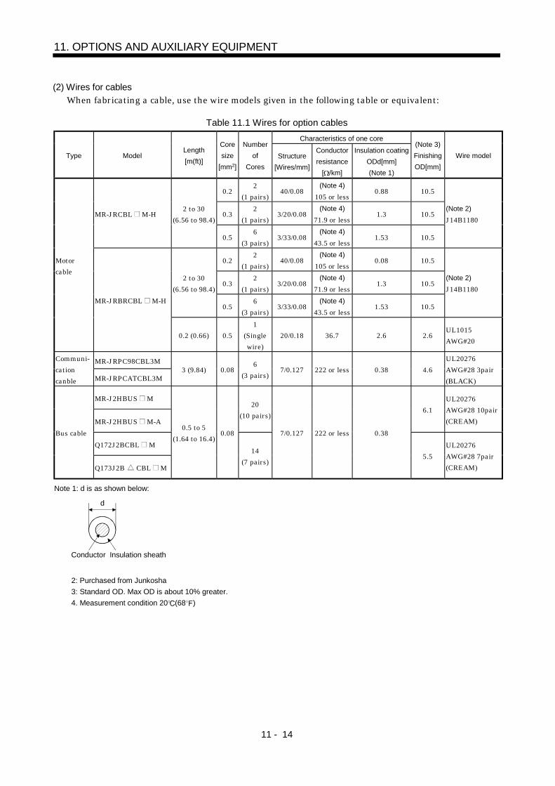
11 - 14
11. OPTIONS AND AUXILIARY EQUIPMENT
(2) Wires for cablesWhen fabricating a cable, use the wire models given in the following table or equivalent:
Table 11.1 Wires for option cablesCharacteristics of one core
Type ModelLength[m(ft)]
Coresize
[mm2]
Numberof
CoresStructure
[Wires/mm]
Conductorresistance
[ /km]
Insulation coatingODd[mm](Note 1)
(Note 3)FinishingOD[mm]
Wire model
0.22
(1 pairs)40/0.08
(Note 4)105 or less
0.88 10.5
0.32
(1 pairs)3/20/0.08
(Note 4)71.9 or less
1.3 10.5MR-JRCBL M-H2 to 30
(6.56 to 98.4)
0.56
(3 pairs)3/33/0.08
(Note 4)43.5 or less
1.53 10.5
(Note 2)J14B1180
0.22
(1 pairs)40/0.08
(Note 4)105 or less
0.08 10.5
0.32
(1 pairs)3/20/0.08
(Note 4)71.9 or less
1.3 10.52 to 30
(6.56 to 98.4)
0.56
(3 pairs)3/33/0.08
(Note 4)43.5 or less
1.53 10.5
(Note 2)J14B1180
Motorcable
MR-JRBRCBL M-H
0.2 (0.66) 0.51
(Singlewire)
20/0.18 36.7 2.6 2.6UL1015AWG#20
MR-JRPC98CBL3MCommuni-cationcanble MR-JRPCATCBL3M
3 (9.84) 0.086
(3 pairs)7/0.127 222 or less 0.38 4.6
UL20276AWG#28 3pair(BLACK)
MR-J2HBUS M
MR-J2HBUS M-A
20(10 pairs)
6.1UL20276AWG#28 10pair(CREAM)
Q172J2BCBL MBus cable
Q173J2B CBL M
0.5 to 5(1.64 to 16.4)
0.08
14(7 pairs)
7/0.127 222 or less 0.38
5.5UL20276AWG#28 7pair(CREAM)
Note 1: d is as shown below:
d
Conductor Insulation sheath
2: Purchased from Junkosha3: Standard OD. Max OD is about 10% greater.4. Measurement condition 20 (68 )
11 - 15
11. OPTIONS AND AUXILIARY EQUIPMENT
11.2.2 Circuit protector
Servo amplifier Circuit protector
MR-J2-03B5 (Note) CP-30BA 1P 1-M5ANote: Use the operation characteristic of "mid-speed type".
11.2.3 Relays
The following relays should be used with the interfaces:Interface Selection example
Relay used for open and close of digital input command(interface DI-1) signals
To prevent defective contacts , use a relay for small signal(twin contacts).(Ex.) Omron : type G2A , MY
11.2.4 Noise reduction techniques
Noises are classified into external noises which enter the servo amplifier to cause it to malfunction andthose radiated by the servo amplifier to cause peripheral devices to malfunction. Since the servo amplifieris an electronic device which handles small signals, the following general noise reduction techniques arerequired.Also, the servo amplifier can be a source of noise as its outputs are chopped by high carrier frequencies. Ifperipheral devices malfunction due to noises produced by the servo amplifier, noise suppression measuresmust be taken. The measures will vary slightly with the routes of noise transmission.(1) Noise reduction techniques
(a) General reduction techniquesAvoid laying power lines (input and output cables) and signal cables side by side or do not bundlethem together. Separate power lines from signal cables.Use shielded, twisted pair cables for connection with the encoder and for control signaltransmission, and connect the shield to the SD terminal.Ground the servo amplifier, servo motor, etc. together at one point (refer to Section 3.7).
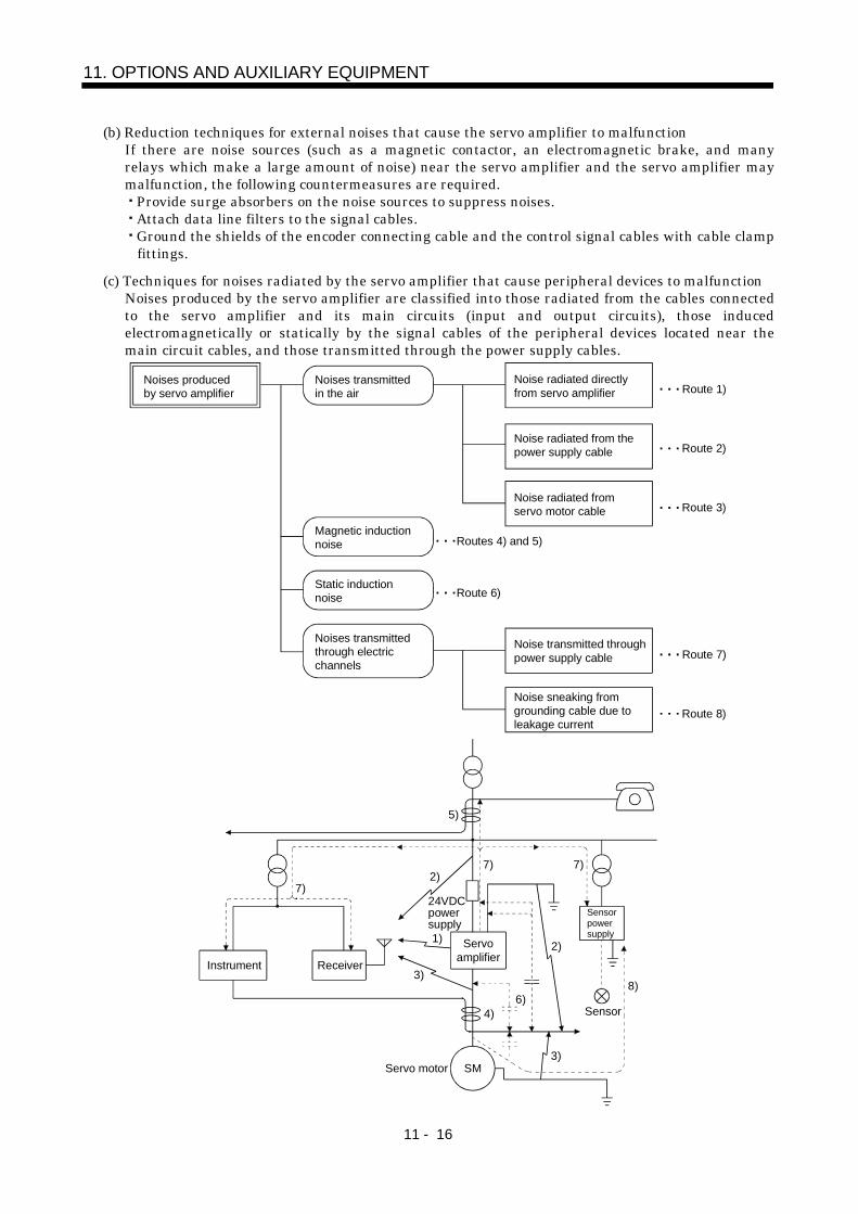
11 - 16
11. OPTIONS AND AUXILIARY EQUIPMENT
(b) Reduction techniques for external noises that cause the servo amplifier to malfunctionIf there are noise sources (such as a magnetic contactor, an electromagnetic brake, and manyrelays which make a large amount of noise) near the servo amplifier and the servo amplifier maymalfunction, the following countermeasures are required.
Provide surge absorbers on the noise sources to suppress noises.Attach data line filters to the signal cables.Ground the shields of the encoder connecting cable and the control signal cables with cable clampfittings.
(c) Techniques for noises radiated by the servo amplifier that cause peripheral devices to malfunctionNoises produced by the servo amplifier are classified into those radiated from the cables connectedto the servo amplifier and its main circuits (input and output circuits), those inducedelectromagnetically or statically by the signal cables of the peripheral devices located near themain circuit cables, and those transmitted through the power supply cables.
Noises produced by servo amplifier
Noises transmitted in the air
Noise radiated directly from servo amplifier
Magnetic induction noise
Static induction noise
Noises transmitted through electric channels
Noise radiated from the power supply cable
Noise radiated from servo motor cable
Noise transmitted through power supply cable
Noise sneaking from grounding cable due to leakage current
Routes 4) and 5)
Route 1)
Route 2)
Route 3)
Route 7)
Route 8)
Route 6)
Instrument Receiver
Servoamplifier
Servo motor SM
2)
2)
8)
1)
7)
7) 7)
5)
3)
4)6)
3)
Sensor
Sensorpowersupply
24VDCpowersupply
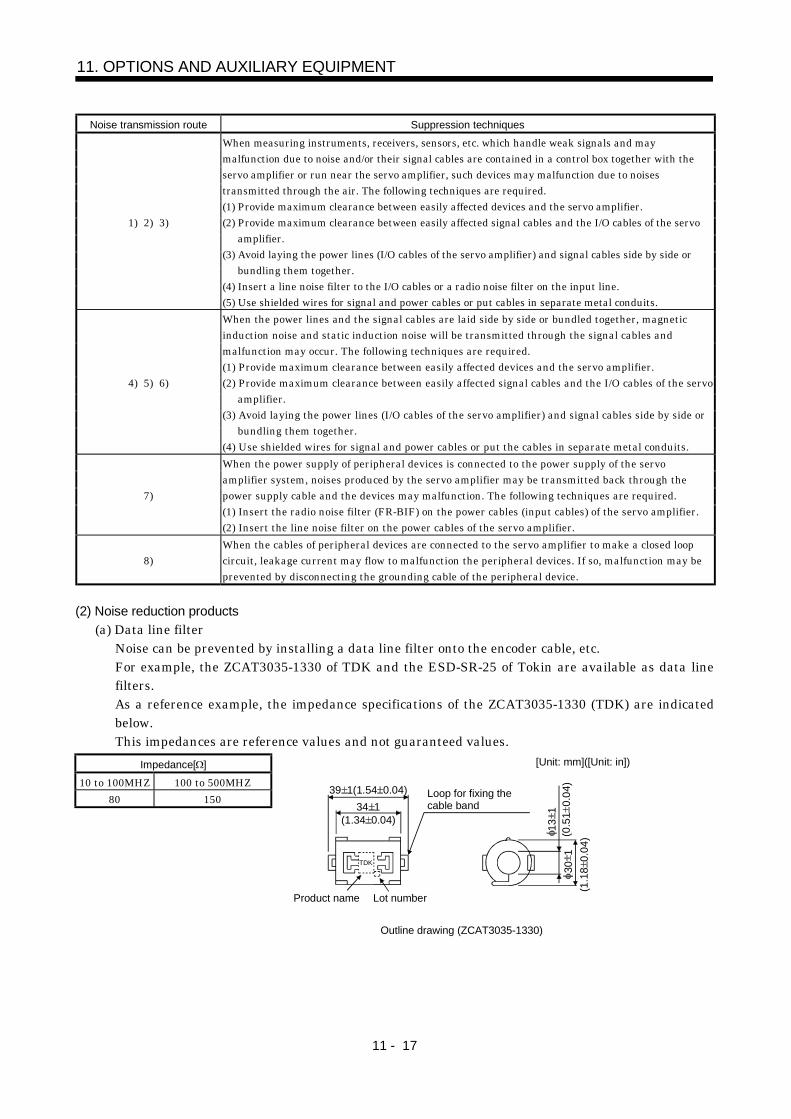
11 - 17
11. OPTIONS AND AUXILIARY EQUIPMENT
Noise transmission route Suppression techniques
1) 2) 3)
When measuring instruments, receivers, sensors, etc. which handle weak signals and maymalfunction due to noise and/or their signal cables are contained in a control box together with theservo amplifier or run near the servo amplifier, such devices may malfunction due to noisestransmitted through the air. The following techniques are required.(1) Provide maximum clearance between easily affected devices and the servo amplifier.(2) Provide maximum clearance between easily affected signal cables and the I/O cables of the servo
amplifier.(3) Avoid laying the power lines (I/O cables of the servo amplifier) and signal cables side by side or
bundling them together.(4) Insert a line noise filter to the I/O cables or a radio noise filter on the input line.(5) Use shielded wires for signal and power cables or put cables in separate metal conduits.
4) 5) 6)
When the power lines and the signal cables are laid side by side or bundled together, magneticinduction noise and static induction noise will be transmitted through the signal cables andmalfunction may occur. The following techniques are required.(1) Provide maximum clearance between easily affected devices and the servo amplifier.(2) Provide maximum clearance between easily affected signal cables and the I/O cables of the servo
amplifier.(3) Avoid laying the power lines (I/O cables of the servo amplifier) and signal cables side by side or
bundling them together.(4) Use shielded wires for signal and power cables or put the cables in separate metal conduits.
7)
When the power supply of peripheral devices is connected to the power supply of the servoamplifier system, noises produced by the servo amplifier may be transmitted back through thepower supply cable and the devices may malfunction. The following techniques are required.(1) Insert the radio noise filter (FR-BIF) on the power cables (input cables) of the servo amplifier.(2) Insert the line noise filter on the power cables of the servo amplifier.
8)When the cables of peripheral devices are connected to the servo amplifier to make a closed loopcircuit, leakage current may flow to malfunction the peripheral devices. If so, malfunction may beprevented by disconnecting the grounding cable of the peripheral device.
(2) Noise reduction products(a) Data line filter
Noise can be prevented by installing a data line filter onto the encoder cable, etc.For example, the ZCAT3035-1330 of TDK and the ESD-SR-25 of Tokin are available as data linefilters.As a reference example, the impedance specifications of the ZCAT3035-1330 (TDK) are indicatedbelow.This impedances are reference values and not guaranteed values.
Impedance[ ]10 to 100MHZ 100 to 500MHZ
80 150
Outline drawing (ZCAT3035-1330)
[Unit: mm]([Unit: in])
Loop for fixing thecable band
Lot number Product name
TDK
39 1(1.54 0.04)34 1
(1.34 0.04)
13
1(0
.51
0.0
4) 3
0 1
(1.1
8 0
.04)
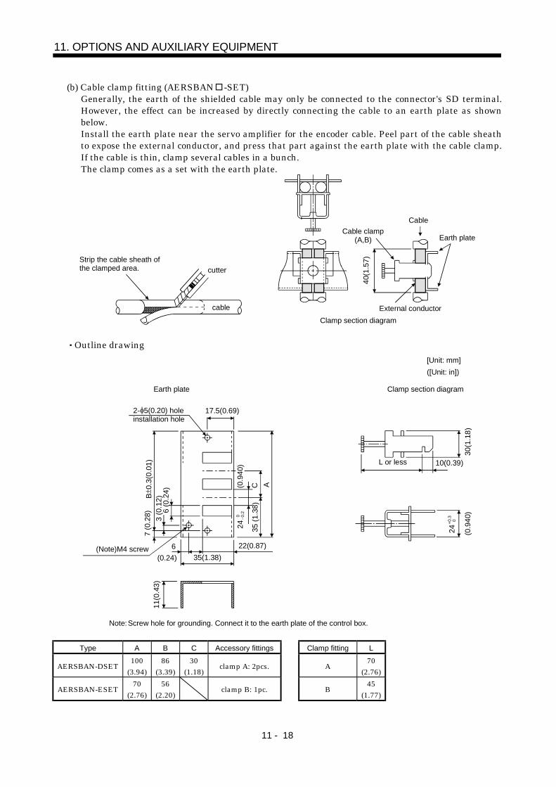
11 - 18
11. OPTIONS AND AUXILIARY EQUIPMENT
(b) Cable clamp fitting (AERSBAN -SET)Generally, the earth of the shielded cable may only be connected to the connector's SD terminal.However, the effect can be increased by directly connecting the cable to an earth plate as shownbelow.Install the earth plate near the servo amplifier for the encoder cable. Peel part of the cable sheathto expose the external conductor, and press that part against the earth plate with the cable clamp.If the cable is thin, clamp several cables in a bunch.The clamp comes as a set with the earth plate.
Strip the cable sheath ofthe clamped area. cutter
cable
Cable clamp(A,B)
Cable
Earth plate
External conductorClamp section diagram
40(1
.57)
Outline drawing
Earth plate Clamp section diagram
(Note)M4 screw
11(0
.43)
3 (0
.12)
6 (0
.24)
C A
6 22(0.87)
17.5(0.69)
35(1.38)
35 (1
.38)
L or less 10(0.39)30
(1.1
8)
7 (0
.28)
24 0 0.
2
Note: Screw hole for grounding. Connect it to the earth plate of the control box.
(0.24)
240.
30
(0.9
40)
(0.9
40)
[Unit: mm]([Unit: in])
B 0
.3(0
.01)
2- 5(0.20) holeinstallation hole
Type A B C Accessory fittings Clamp fitting L
AERSBAN-DSET 100(3.94)
86(3.39)
30(1.18) clamp A: 2pcs. A 70
(2.76)
AERSBAN-ESET 70(2.76)
56(2.20) clamp B: 1pc. B 45
(1.77)
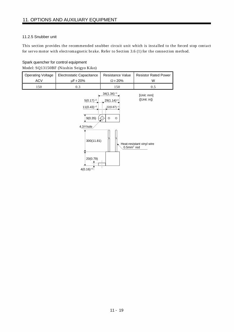
11 - 19
11. OPTIONS AND AUXILIARY EQUIPMENT
11.2.5 Snubber unit
This section provides the recommended snubber circuit unit which is installed to the forced stop contactfor servo motor with electromagnetic brake. Refer to Section 3.6 (1) for the connection method.
Spark quencher for control equipmentModel: SQ13150BF (Nisshin Seigyo Kiko)
Operating VoltageACV
Electrostatic CapacitanceF 20%
Resistance Value 20%
Resistor Rated PowerW
150 0.3 150 0.5
4.3 hole
1
1
Heat-resistant vinyl wire0.5mm2 red
9(0.35)
300(11.81)
20(0.79)
4(0.16)
5(0.17)
34(1.34) 1
29(1.14) 1
22(0.87) 11(0.43) 11
[Unit: mm]([Unit: in])

11 - 20
11. OPTIONS AND AUXILIARY EQUIPMENT
MEMO
REVISIONS
*The manual number is given on the bottom left of the back cover.Print Data *Manual Number Revision
Nov.,2000 SH(NA)030005-A First editionMay.,2003 SH(NA)030005-B SAFETY INSTRUCTIONS 3: Partial text addition
SAFETY INSTRUCTIONS 4 (1): Partial text addition, Note additionSAFETY INSTRUCTIONS (7): ChangeAddition of About processing of wasteAddition of FOR MAXIMUM SAFETYAddition of EEP-ROM lifePartial addition of text to CONFORMANCE WITH UL/C-UL STANDARDSection 1.4 (1): Partial figure changeSection 2.4 (2): Text changeSection 3.1: Partial POINT sentence addition, Note table changeSection 3.3: Figure change, Note changeSection 3.5: Partial CAUTION sentence additionSection 3.6 (3) (c): POINT additionSection 3.6 (3) (e): POINT additionSection 4.1 (1) (d): Text changeSection 5.2 (1): Parameter No. 1 to 6 reexamination
Note 2 additionParameter No. 25 reexamination
Section 5.2 (2): Parameter No. 1 to 6 reexaminationParameter No. 19 text changeParameter No. 25 reexamination
Chapter 7: Partial table reexaminationSection 8.1: Partial text changeSection 8.2: POINT sentence addition, partial alarm 11 to 16, 20, 37, 50,
51 reexaminationSection 9.2 (2): Table additionSection 9.2 (3): Overall reexaminationSection 9.2 (4): Item additionSection 10.1: Note additionSection 11.1.1 (1): Table change, 13), 14) additionSection 11.1.1 (2): Partial POINT sentence additionSection 11.1.1 (4): Overall reexaminationSection 11.2.1 (1): Partial text additionSection 11.2.1 (2): Table change

HEAD OFFICE:MITSUBISHI DENKI BLDG MARUNOUCHI TOKYO 100-8310
SH (NA) 030005-B (0305) MEE Printed in Japan Specifications subject to change without notice.This Instruction Manual uses recycled paper.
MODEL
MODELCODE
![Dualities and Dynamics in 2+1 DimensionsParticle / vortex duality [Peskin 78; Dasgupta, Halperin 81] O(2) vector model gauged O(2) vector model L= j@˚j 2+ j˚j4 + mj˚j2 L= jF j2](https://img.pdfslide.us/doc/110x75/5fa7a177d76c1a538711eaf9/dualities-and-dynamics-in-21-dimensions-particle-vortex-duality-peskin-78-dasgupta.jpg)