Embed Size (px)
Citation preview

J2-Su
per S
eriesM
R-J2S
- B S
ervo A
mp
lifier Instru
ction
Man
ual
SH (NA) 030007-G (0711) MEE Printed in Japan Specifications subject to change without notice.This Instruction Manual uses recycled paper.
MODEL
MODELCODE 1CW502
MR-J2S-B GIJUTU SIRYOU
G
General-Purpose AC Servo
MODEL
MR-J2S- BSERVO AMPLIFIERINSTRUCTION MANUAL
SSCNET Compatible
J2-Super Series
GHEAD OFFICE : TOKYO BLDG MARUNOUCHI TOKYO 100-8310

A - 1
Safety Instructions (Always read these instructions before using the equipment.)
Do not attempt to install, operate, maintain or inspect the servo amplifier and servo motor until you have readthrough this Instruction Manual, Installation guide, Servo motor Instruction Manual and appended documentscarefully and can use the equipment correctly. Do not use the servo amplifier and servo motor until you have afull knowledge of the equipment, safety information and instructions.In this Instruction Manual, the safety instruction levels are classified into "WARNING" and "CAUTION".
WARNING Indicates that incorrect handling may cause hazardous conditions,resulting in death or severe injury.
CAUTION Indicates that incorrect handling may cause hazardous conditions,resulting in medium or slight injury to personnel or may cause physicaldamage.
Note that the CAUTION level may lead to a serious consequence according to conditions. Please follow theinstructions of both levels because they are important to personnel safety.What must not be done and what must be done are indicated by the following diagrammatic symbols:
: Indicates what must not be done. For example, "No Fire" is indicated by .
: Indicates what must be done. For example, grounding is indicated by .
In this Instruction Manual, instructions at a lower level than the above, instructions for other functions, and soon are classified into "POINT".After reading this Instruction Manual, always keep it accessible to the operator.
A - 2
1. To prevent electric shock, note the following:
WARNINGBefore wiring or inspection, turn off the power and wait for 15 minutes or more until the charge lamp turnsoff. Then, confirm that the voltage between P and N is safe with a voltage tester and others. Otherwise, anelectric shock may occur. In addition, always confirm from the front of the servo amplifier, whether thecharge lamp is off or not.
Connect the servo amplifier and servo motor to ground.
Any person who is involved in wiring and inspection should be fully competent to do the work.
Do not attempt to wire the servo amplifier and servo motor until they have been installed. Otherwise, youmay get an electric shock.
Operate the switches with dry hand to prevent an electric shock.
The cables should not be damaged, stressed, loaded, or pinched. Otherwise, you may get an electric shock.
During power-on or operation, do not open the front cover of the servo amplifier. You may get an electricshock.
Do not operate the servo amplifier with the front cover removed. High-voltage terminals and charging areaare exposed and you may get an electric shock.
Except for wiring or periodic inspection, do not remove the front cover even of the servo amplifier if thepower is off. The servo amplifier is charged and you may get an electric shock.
2. To prevent fire, note the following:
CAUTIONInstall the servo amplifier, servo motor and regenerative resistor on incombustible material. Installing themdirectly or close to combustibles will lead to a fire.
Always connect a magnetic contactor (MC) between the main circuit power supply and L1, L2, and L3 ofthe servo amplifier, and configure the wiring to be able to shut down the power supply on the side of theservo amplifier’s power supply. If a magnetic contactor (MC) is not connected, continuous flow of a largecurrent may cause a fire when the servo amplifier malfunctions.
When a regenerative resistor is used, use an alarm signal to switch main power off. Otherwise, aregenerative transistor fault or the like may overheat the regenerative resistor, causing a fire.
3. To prevent injury, note the follow
CAUTIONOnly the voltage specified in the Instruction Manual should be applied to each terminal. Otherwise, a burst,damage, etc. may occur.
Connect the terminals correctly to prevent a burst, damage, etc.
Ensure that polarity ( , ) is correct. Otherwise, a burst, damage, etc. may occur.
Take safety measures, e.g. provide covers, to prevent accidental contact of hands and parts (cables, etc.)with the servo amplifier heat sink, regenerative resistor, servo motor, etc. since they may be hot whilepower is on or for some time after power-off. Their temperatures may be high and you may get burnt or aparts may damaged.
During operation, never touch the rotating parts of the servo motor. Doing so can cause injury.
A - 3
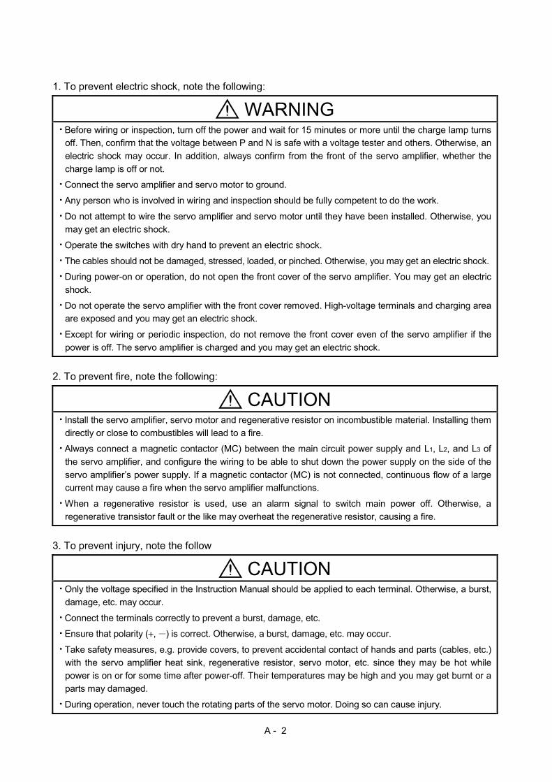
4. Additional instructionsThe following instructions should also be fully noted. Incorrect handling may cause a fault, injury, electricshock, etc.
(1) Transportation and installation
CAUTIONTransport the products correctly according to their weights.Stacking in excess of the specified number of products is not allowed.Do not carry the servo motor by the cables, shaft or encoder.Do not hold the front cover to transport the servo amplifier. The servo amplifier may drop.Install the servo amplifier in a load-bearing place in accordance with the Instruction Manual.Do not climb or stand on servo equipment. Do not put heavy objects on equipment.The servo amplifier and servo motor must be installed in the specified direction.Leave specified clearances between the servo amplifier and control enclosure walls or other equipment.Do not install or operate the servo amplifier and servo motor which has been damaged or has any partsmissing.Provide adequate protection to prevent screws and other conductive matter, oil and other combustiblematter from entering the servo amplifier and servo motor.Do not drop or strike servo amplifier or servo motor. Isolate from all impact loads.When you keep or use it, please fulfill the following environmental conditions.
ConditionsEnvironmentServo amplifier Servo motor
[ ] 0 to 55 (non-freezing) 0 to 40 (non-freezing)Inoperation [ ] 32 to 131 (non-freezing) 32 to 104 (non-freezing)
[ ] 20 to 65 (non-freezing) 15 to 70 (non-freezing)Ambienttemperature
In storage[ ] 4 to 149 (non-freezing) 5 to 158 (non-freezing)
In operation 90%RH or less (non-condensing) 80%RH or less (non-condensing)Ambienthumidity In storage 90%RH or less (non-condensing)Ambience Indoors (no direct sunlight) Free from corrosive gas, flammable gas, oil mist, dust and dirtAltitude Max. 1000m (3280 ft) above sea level
HC-KFS SeriesHC-MFS SeriesHC-UFS13 to 73
X Y : 49
HC-SFS81HC-SFS52 to 152HC-SFS53 to 153HC-RFS Series
HC-UFS 72 152
X Y : 24.5
HC-SFS121 201HC-SFS202 352HC-SFS203 353HC-UFS202 to 502
X : 24.5Y : 49
HC-SFS301HC-SFS502 to 702
X : 24.5Y : 29.4
[m/s2] 5.9 or less
HA-LFS11K2 to 22K2 X : 11.7Y : 29.4
HC-KFS SeriesHC-MFS Series
HC-UFS 13 to 73X Y : 161
HC-SFS81HC-SFS52 to 152HC-SFS53 to 153HC-RFS Series
HC-UFS 72 152
X Y : 80
HC-SFS121 201HC-SFS202 352HC-SFS203 353HC-UFS202 to 502
X : 80Y : 161
HC-SFS301HC-SFS502 to 702
X : 80Y : 96
(Note)Vibration
[ft/s2] 19.4 or less
HA-LFS11K2 to 22K2 X : 38Y : 96
Note. Except the servo motor with reduction gear.

A - 4
CAUTIONSecurely attach the servo motor to the machine. If attach insecurely, the servo motor may come off duringoperation.
The servo motor with reduction gear must be installed in the specified direction to prevent oil leakage.
Take safety measures, e.g. provide covers, to prevent accidental access to the rotating parts of the servomotor during operation.
Never hit the servo motor or shaft, especially when coupling the servo motor to the machine. The encodermay become faulty.
Do not subject the servo motor shaft to more than the permissible load. Otherwise, the shaft may break.
When the equipment has been stored for an extended period of time, consult Mitsubishi.
(2) Wiring
CAUTIONWire the equipment correctly and securely. Otherwise, the servo motor may misoperate.
Do not install a power capacitor, surge absorber or radio noise filter (FR-BIF option) between the servomotor and servo amplifier.
Connect the output terminals (U, V, W) correctly. Otherwise, the servo motor will operate improperly.
Connect the servo motor power terminal (U, V, W) to the servo motor power input terminal (U, V, W)directly. Do not let a magnetic contactor, etc. intervene.
U
Servo motor
MV
W
U
V
W
U
MV
W
U
V
W
Servo amplifier Servo motorServo amplifier
Do not connect AC power directly to the servo motor. Otherwise, a fault may occur.
The surge absorbing diode installed on the DC output signal relay of the servo amplifier must be wired inthe specified direction. Otherwise, the forced stop (EM1) and other protective circuits may not operate.
RA
COM(24VDC)
Controloutputsignal
Servoamplifier
COM(24VDC)
RA
Controloutputsignal
Servoamplifier
When the cable is not tightened enough to the terminal block (connector), the cable or terminal block(connector) may generate heat because of the poor contact. Be sure to tighten the cable with specifiedtorque.

A - 5
(3) Test run adjustment
CAUTIONBefore operation, check the parameter settings. Improper settings may cause some machines to performunexpected operation.
The parameter settings must not be changed excessively. Operation will be insatiable.
(4) Usage
CAUTIONProvide a forced stop circuit to ensure that operation can be stopped and power switched off immediately.
Any person who is involved in disassembly and repair should be fully competent to do the work.
Before resetting an alarm, make sure that the run signal of the servo amplifier is off to prevent anaccident. A sudden restart is made if an alarm is reset with the run signal on.
Do not modify the equipment.
Use a noise filter, etc. to minimize the influence of electromagnetic interference, which may be caused byelectronic equipment used near the servo amplifier.
Burning or breaking a servo amplifier may cause a toxic gas. Do not burn or break a servo amplifier.
Use the servo amplifier with the specified servo motor.
The electromagnetic brake on the servo motor is designed to hold the motor shaft and should not be usedfor ordinary braking.
For such reasons as service life and mechanical structure (e.g. where a ball screw and the servo motorare coupled via a timing belt), the electromagnetic brake may not hold the motor shaft. To ensure safety,install a stopper on the machine side.
(5) Corrective actions
CAUTIONWhen it is assumed that a hazardous condition may take place at the occur due to a power failure or aproduct fault, use a servo motor with electromagnetic brake or an external brake mechanism for thepurpose of prevention.
Configure the electromagnetic brake circuit so that it is activated not only by the interface unit signals butalso by a forced stop (EM1).
EM1RA
24VDC
Contacts must be open whenservo-off, when an alarm occurrenceand when an electromagnetic brake interlock (MBR).
Electromagnetic brake
Servo motor
Circuit must be opened duringforced stop (EM1).
When any alarm has occurred, eliminate its cause, ensure safety, and deactivate the alarm beforerestarting operation.
When power is restored after an instantaneous power failure, keep away from the machine because themachine may be restarted suddenly (design the machine so that it is secured against hazard if restarted).

A - 6
(6) Maintenance, inspection and parts replacement
CAUTIONWith age, the electrolytic capacitor of the servo amplifier will deteriorate. To prevent a secondary accidentdue to a fault, it is recommended to replace the electrolytic capacitor every 10 years when used in generalenvironment.Please consult our sales representative.
(7) General instruction
To illustrate details, the equipment in the diagrams of this Instruction Manual may have been drawnwithout covers and safety guards. When the equipment is operated, the covers and safety guards mustbe installed as specified. Operation must be performed in accordance with this Instruction Manual.
About processing of waste When you discard servo amplifier, a battery (primary battery), and other option articles, please follow the law ofeach country (area).
FOR MAXIMUM SAFETYThese products have been manufactured as a general-purpose part for general industries, and have notbeen designed or manufactured to be incorporated in a device or system used in purposes related tohuman life.Before using the products for special purposes such as nuclear power, electric power, aerospace,medicine, passenger movement vehicles or under water relays, contact Mitsubishi.These products have been manufactured under strict quality control. However, when installing the productwhere major accidents or losses could occur if the product fails, install appropriate backup or failsafefunctions in the system.
EEP-ROM lifeThe number of write times to the EEP-ROM, which stores parameter settings, etc., is limited to 100,000. Ifthe total number of the following operations exceeds 100,000, the servo amplifier and/or converter unit mayfail when the EEP-ROM reaches the end of its useful life.
Write to the EEP-ROM due to parameter setting changesWrite to the EEP-ROM due to device changes
Precautions for Choosing the ProductsMitsubishi will not be held liable for damage caused by factors found not to be the cause of Mitsubishi;machine damage or lost profits caused 0y faults in the Mitsubishi products; damage, secondary damage,accident compensation caused by special factors unpredictable by Mitsubishi; damages to products otherthan Mitsubishi products; and to other duties.
A - 7
COMPLIANCE WITH EC DIRECTIVES1. WHAT ARE EC DIRECTIVES?The EC directives were issued to standardize the regulations of the EU countries and ensure smoothdistribution of safety-guaranteed products. In the EU countries, the machinery directive (effective inJanuary, 1995), EMC directive (effective in January, 1996) and low voltage directive (effective in January,1997) of the EC directives require that products to be sold should meet their fundamental safetyrequirements and carry the CE marks (CE marking). CE marking applies to machines and equipmentinto which servo amplifiers have been installed.
(1) EMC directiveThe EMC directive applies not to the servo units alone but to servo-incorporated machines andequipment. This requires the EMC filters to be used with the servo-incorporated machines andequipment to comply with the EMC directive. For specific EMC directive conforming methods, refer tothe EMC Installation Guidelines (IB(NA)67310).
(2) Low voltage directiveThe low voltage directive applies also to servo units alone. Hence, they are designed to comply withthe low voltage directive.This servo is certified by TUV, third-party assessment organization, to comply with the low voltagedirective.
(3) Machine directiveNot being machines, the servo amplifiers need not comply with this directive.
2. PRECAUTIONS FOR COMPLIANCE(1) Servo amplifiers and servo motors used
Use the servo amplifiers and servo motors which comply with the standard model.
Servo amplifier :MR-J2S-10B to MR-J2S-22KB MR-J2S-10B1 to MR-J2S-40B1
Servo motor :HC-KFS HC-MFS HC-SFS HC-RFS HC-UFS HA-LFS HC-LFS
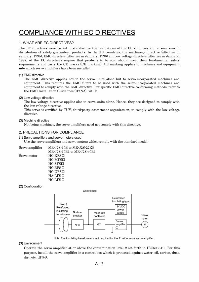
(2) Configuration
Reinforcedinsulatingtransformer
NFB MC M
No-fusebreaker
Magneticcontactor
Reinforcedinsulating type
24VDCpowersupply
Servoamplifier
Servomotor
Control box
(Note)
Note. The insulating transformer is not required for the 11kW or more servo amplifier.
(3) EnvironmentOperate the servo amplifier at or above the contamination level 2 set forth in IEC60664-1. For thispurpose, install the servo amplifier in a control box which is protected against water, oil, carbon, dust,dirt, etc. (IP54).
A - 8
(4) Power supply(a) Operate the servo amplifier 7kW or less to meet the requirements of the overvoltage category II set
forth in IEC60664-1. For this purpose, a reinforced insulating transformer conforming to the IECor EN standard should be used in the power input section.Since the 11kW or more servo amplifier can be used under the conditions of the overvoltagecategory III set forth in IEC60664-1, a reinforced insulating transformer is not required in thepower input section.
(b) When supplying interface power from external, use a 24VDC power supply which has beeninsulation-reinforced in I/O.
(5) Grounding(a) To prevent an electric shock, always connect the protective earth (PE) terminals (marked ) of the
servo amplifier to the protective earth (PE) of the control box.
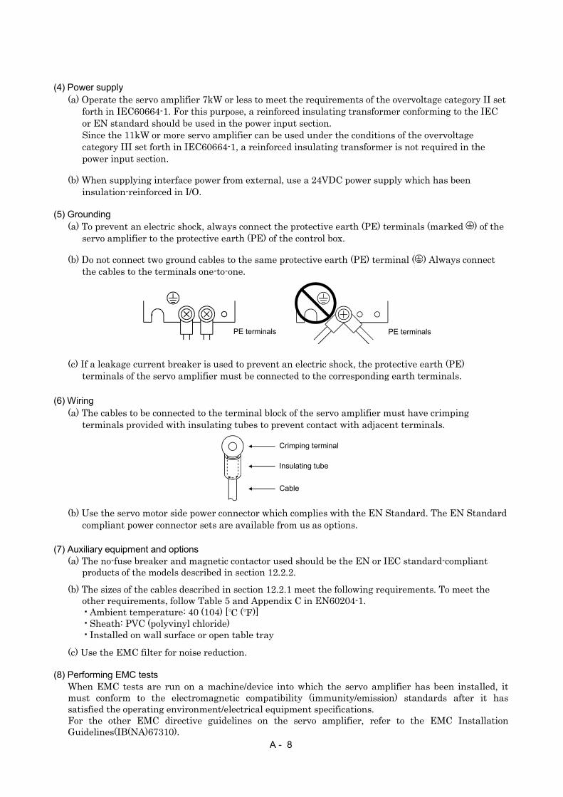
(b) Do not connect two ground cables to the same protective earth (PE) terminal ( ) Always connectthe cables to the terminals one-to-one.
PE terminals PE terminals
(c) If a leakage current breaker is used to prevent an electric shock, the protective earth (PE)terminals of the servo amplifier must be connected to the corresponding earth terminals.
(6) Wiring(a) The cables to be connected to the terminal block of the servo amplifier must have crimping
terminals provided with insulating tubes to prevent contact with adjacent terminals.
Crimping terminal
Insulating tube
Cable
(b) Use the servo motor side power connector which complies with the EN Standard. The EN Standardcompliant power connector sets are available from us as options.
(7) Auxiliary equipment and options(a) The no-fuse breaker and magnetic contactor used should be the EN or IEC standard-compliant
products of the models described in section 12.2.2.
(b) The sizes of the cables described in section 12.2.1 meet the following requirements. To meet theother requirements, follow Table 5 and Appendix C in EN60204-1.
Ambient temperature: 40 (104) [ ( )]Sheath: PVC (polyvinyl chloride)Installed on wall surface or open table tray
(c) Use the EMC filter for noise reduction.
(8) Performing EMC testsWhen EMC tests are run on a machine/device into which the servo amplifier has been installed, itmust conform to the electromagnetic compatibility (immunity/emission) standards after it hassatisfied the operating environment/electrical equipment specifications.For the other EMC directive guidelines on the servo amplifier, refer to the EMC InstallationGuidelines(IB(NA)67310).

A - 9
CONFORMANCE WITH UL/C-UL STANDARD(1) Servo amplifiers and servo motors used
Use the servo amplifiers and servo motors which comply with the standard model.
Servo amplifier :MR-J2S-10B to MR-J2S-22KB MR-J2S-10B1 to MR-J2S-40B1
Servo motor :HC-KFS HC-MFS HC-SFS HC-RFS HC-UFS HA-LFS HC-LFS
(2) InstallationInstall a cooling fan of 100CFM (2.8m3/min) air flow 4 in (10.16 cm) above the servo amplifier orprovide cooling of at least equivalent capability.
(3) Short circuit ratingThis servo amplifier conforms to the circuit whose peak current is limited to 5000A or less. Havingbeen subjected to the short-circuit tests of the UL in the alternating-current circuit, the servoamplifier conforms to the above circuit.
(4) Capacitor discharge timeThe capacitor discharge time is as listed below. To ensure safety, do not touch the charging section for10 minutes after power-off.
Servo amplifier Discharge time[min]
MR-J2S-10B(1) 20B(1) 1MR-J2S-40B(1) 60B 2MR-J2S-70B to 350B 3MR-J2S-500B 700B 5
MR-J2S-11KB 4MR-J2S-15KB 6MR-J2S-22KB 8
(5) Options and auxiliary equipmentUse UL/C-UL standard-compliant products.
(6) Attachment of a servo motorFor the flange size of the machine side where the servo motor is installed, refer to “CONFORMANCEWITH UL/C-UL STANDARD” in the Servo Motor Instruction Manual.
(7) About wiring protectionFor installation in United States, branch circuit protection must be provided, in accordance with theNational Electrical Code and any applicable local codes.For installation in Canada, branch circuit protection must be provided, in accordance with the CanadaElectrical Code and any applicable provincial codes.
A - 10
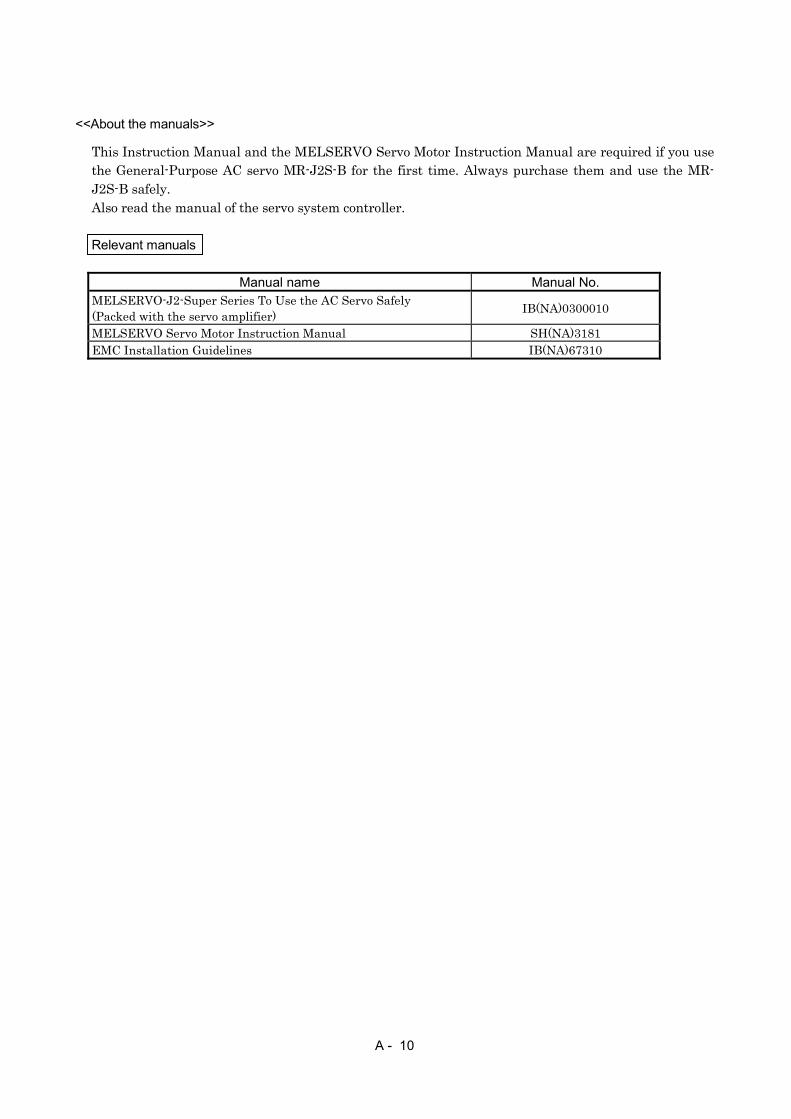
<<About the manuals>>
This Instruction Manual and the MELSERVO Servo Motor Instruction Manual are required if you usethe General-Purpose AC servo MR-J2S-B for the first time. Always purchase them and use the MR-J2S-B safely.Also read the manual of the servo system controller.
Relevant manuals
Manual name Manual No.MELSERVO-J2-Super Series To Use the AC Servo Safely(Packed with the servo amplifier) IB(NA)0300010
MELSERVO Servo Motor Instruction Manual SH(NA)3181EMC Installation Guidelines IB(NA)67310
1
CONTENTS
1. FUNCTIONS AND CONFIGURATION 1- 1 to 1-22
1.1 Introduction.............................................................................................................................................. 1- 11.2 Function block diagram .......................................................................................................................... 1- 21.3 Servo amplifier standard specifications ................................................................................................ 1- 51.4 Function list ............................................................................................................................................. 1- 61.5 Model code definition .............................................................................................................................. 1- 71.6 Combination with servo motor............................................................................................................... 1- 81.7 Structure................................................................................................................................................... 1- 9
1.7.1 Parts identification ........................................................................................................................... 1- 91.7.2 Removal and reinstallation of the front cover .............................................................................. 1-14
1.8 Servo system with auxiliary equipment............................................................................................... 1-17
2. INSTALLATION 2- 1 to 2- 4
2.1 Environmental conditions....................................................................................................................... 2- 12.2 Installation direction and clearances .................................................................................................... 2- 22.3 Keep out foreign materials ..................................................................................................................... 2- 32.4 Cable stress .............................................................................................................................................. 2- 4
3. SIGNALS AND WIRING 3- 1 to 3-38
3.1 Connection example of control signal system....................................................................................... 3- 23.1.1 MR-J2S-700B or less ........................................................................................................................ 3- 23.1.2 MR-J2S-11KB or more ..................................................................................................................... 3- 4
3.2 I/O signals................................................................................................................................................. 3- 63.2.1 Connectors and signal arrangements............................................................................................. 3- 63.2.2 Signal explanations .......................................................................................................................... 3- 8
3.3 Alarm occurrence timing chart .............................................................................................................. 3- 93.4 Interfaces................................................................................................................................................. 3-10
3.4.1 Common line .................................................................................................................................... 3-103.4.2 Detailed description of the interfaces ............................................................................................ 3-11
3.5 Power line circuit.................................................................................................................................... 3-143.5.1 Connection example......................................................................................................................... 3-143.5.2 Terminals.......................................................................................................................................... 3-163.5.3 Power-on sequence........................................................................................................................... 3-17
3.6 Connection of servo amplifier and servo motor ................................................................................... 3-183.6.1 Connection instructions .................................................................................................................. 3-183.6.2 Connection diagram......................................................................................................................... 3-183.6.3 I/O terminals .................................................................................................................................... 3-20
3.7 Servo motor with electromagnetic brake ............................................................................................. 3-223.8 Grounding................................................................................................................................................ 3-263.9 Servo amplifier terminal block (TE2) wiring method ......................................................................... 3-27
3.9.1 For servo amplifier produced later than January, 2006.............................................................. 3-273.9.2 For servo amplifier produced earlier than December, 2005........................................................ 3-29
3.10 Instructions for the 3M connector....................................................................................................... 3-303.11 Control axis selection ........................................................................................................................... 3-31

2
3.12 Power line circuit of the MR-J2S-11KB to MR-J2S-22KB............................................................... 3-323.12.1 Connection example ...................................................................................................................... 3-333.12.2 Servo amplifier terminals ............................................................................................................. 3-343.12.3 Servo motor terminals................................................................................................................... 3-35
4. OPERATION AND DISPLAY 4- 1 to 4- 8
4.1 When switching power on for the first time.......................................................................................... 4- 14.2 Start up..................................................................................................................................................... 4- 24.3 Servo amplifier display ........................................................................................................................... 4- 44.4 Test operation mode ................................................................................................................................ 4- 6
5. PARAMETERS 5- 1 to 5-20
5.1 Parameter write inhibit .......................................................................................................................... 5- 15.2 Lists........................................................................................................................................................... 5- 15.3 Analog monitor ....................................................................................................................................... 5-145.4 Replacement of MR-J2- B by MR-J2S- B....................................................................................... 5-17
5.4.1 Main modifications made to the parameters ................................................................................ 5-175.4.2 Explanation of the modified parameters....................................................................................... 5-18
6. GENERAL GAIN ADJUSTMENT 6- 1 to 6-12
6.1 Different adjustment methods ............................................................................................................... 6- 16.1.1 Adjustment on a single servo amplifier.......................................................................................... 6- 16.1.2 Adjustment using MR Configurator (servo configuration software) ........................................... 6- 3
6.2 Auto tuning .............................................................................................................................................. 6- 46.2.1 Auto tuning mode ............................................................................................................................. 6- 46.2.2 Auto tuning mode operation ............................................................................................................ 6- 56.2.3 Adjustment procedure by auto tuning............................................................................................ 6- 66.2.4 Response level setting in auto tuning mode................................................................................... 6- 7
6.3 Manual mode 1 (simple manual adjustment)....................................................................................... 6- 86.3.1 Operation of manual mode 1 ........................................................................................................... 6- 86.3.2 Adjustment by manual mode 1 ....................................................................................................... 6- 8
6.4 Interpolation mode ................................................................................................................................. 6-116.5 Differences in auto tuning between MELSERVO-J2 and MELSERVO-J2-Super .......................... 6-12
6.5.1 Response level setting ..................................................................................................................... 6-126.5.2 Auto tuning selection....................................................................................................................... 6-12
7. SPECIAL ADJUSTMENT FUNCTIONS 7- 1 to 7-10
7.1 Function block diagram .......................................................................................................................... 7- 17.2 Machine resonance suppression filter ................................................................................................... 7- 17.3 Adaptive vibration suppression control................................................................................................. 7- 37.4 Low-pass filter ......................................................................................................................................... 7- 47.5 Gain changing function........................................................................................................................... 7- 5
7.5.1 Applications....................................................................................................................................... 7- 57.5.2 Function block diagram.................................................................................................................... 7- 57.5.3 Parameters ........................................................................................................................................ 7- 67.5.4 Gain changing operation.................................................................................................................. 7- 8

3
8. INSPECTION 8- 1 to 8- 2
9. TROUBLESHOOTING 9- 1 to 9- 8
9.1 Alarms and warning list ......................................................................................................................... 9- 19.2 Remedies for alarms................................................................................................................................ 9- 29.3 Remedies for warnings............................................................................................................................ 9- 8
10. OUTLINE DIMENSION DRAWINGS 10- 1 to 10-10
10.1 Servo amplifiers................................................................................................................................... 10- 110.2 Connectors............................................................................................................................................ 10- 8
11. CHARACTERISTICS 11- 1 to 11- 8
11.1 Overload protection characteristics ................................................................................................... 11- 111.2 Power supply equipment capacity and generated loss .................................................................... 11- 211.3 Dynamic brake characteristics........................................................................................................... 11- 5
11.3.1 Dynamic brake operation............................................................................................................. 11- 511.3.2 The dynamic brake at the load inertia moment ........................................................................ 11- 7
11.4 Encoder cable flexing life .................................................................................................................... 11- 711.5 Inrush currents at power-on of main circuit and control circuit .................................................... 11- 8
12. OPTIONS AND AUXILIARY EQUIPMENT 12- 1 to 12-64
12.1 Options.................................................................................................................................................. 12- 112.1.1 Regenerative options .................................................................................................................... 12- 112.1.2 FR-BU2 brake unit ......................................................................................................................12-1012.1.3 Power regeneration converter ....................................................................................................12-1712.1.4 External dynamic brake..............................................................................................................12-2012.1.5 Cables and connectors.................................................................................................................12-2312.1.6 Maintenance junction card (MR-J2CN3TM) ............................................................................12-3612.1.7 Battery (MR-BAT, A6BAT).........................................................................................................12-3712.1.8 MR Configurator (servo configurations software) ....................................................................12-3712.1.9 Power regeneration common converter .....................................................................................12-3912.1.10 Heat sink outside mounting attachment (MR-JACN)...........................................................12-43
12.2 Auxiliary equipment ..........................................................................................................................12-4612.2.1 Recommended wires....................................................................................................................12-4612.2.2 No-fuse breakers, fuses, magnetic contactors...........................................................................12-4912.2.3 Power factor improving reactors ................................................................................................12-4912.2.4 Power factor improving DC reactors..........................................................................................12-5012.2.5 Relays............................................................................................................................................12-5112.2.6 Surge absorbers ...........................................................................................................................12-5112.2.7 Noise reduction techniques.........................................................................................................12-5212.2.8 Leakage current breaker.............................................................................................................12-5912.2.9 EMC filter.....................................................................................................................................12-61
13. ABSOLUTE POSITION DETECTION SYSTEM 13- 1 to 13- 4
13.1 Features................................................................................................................................................ 13- 1

4
13.2 Specifications ....................................................................................................................................... 13- 213.3 Battery installation procedure ........................................................................................................... 13- 313.4 Confirmation of absolute position detection data............................................................................. 13- 4
APPENDIX App- 2
App 1. Combination of servo amplifier and servo motor ...................................................................... App- 1App 2. Change of connector sets to the RoHS compatible products .................................................... App- 2
5
Optional Servo Motor Instruction Manual CONTENTS
The rough table of contents of the optional MELSERVO Servo Motor Instruction Manual is introducedhere for your reference. Note that the contents of the Servo Motor Instruction Manual are not included inthe Servo Amplifier Instruction Manual.
1. INTRODUCTION
2. INSTALLATION
3. CONNECTORS USED FOR SERVO MOTOR WIRING
4. INSPECTION
5. SPECIFICATIONS
6. CHARACTERISTICS
7. OUTLINE DIMENSION DRAWINGS
8. CALCULATION METHODS FOR DESIGNING

6
MEMO

1 - 1
1. FUNCTIONS AND CONFIGURATION
1. FUNCTIONS AND CONFIGURATION
1.1 Introduction
The Mitsubishi MELSERVO-J2-Super series general-purpose AC servo is based on the MELSERVO-J2series and has further higher performance and higher functions.It is connected with a servo system controller or similar device via a serial bus (SSCNET) and the servoamplifier reads position data directly to perform operation.Data from a command unit controls the speed and rotation direction of the servo motor and executesprecision positioning.A torque limit is imposed on the servo amplifier by the clamp circuit to protect the power transistor in themain circuit from overcurrent due to sudden acceleration/deceleration or overload. The torque limit valuecan be changed to any value with an external analog input or the parameter.As this new series has the RS-232C serial communication function, a MR Configurator (servoconfiguration software)-installed personal computer or the like can be used to perform parameter setting,test operation, status display monitoring, gain adjustment, etc.With real-time auto tuning, you can automatically adjust the servo gains according to the machine.The MELSERVO-J2-Super series servo motor is equipped with an absolute position encoder which hasthe resolution of 131072 pulses/rev to ensure more accurate control as compared to the MELSERVO-J2series. Simply adding a battery to the servo amplifier makes up an absolute position detection system.This makes home position return unnecessary at power-on or alarm occurrence by setting a home positiononce.

1 - 2
1. FUNCTIONS AND CONFIGURATION
1.2 Function block diagram
The function block diagram of this servo is shown below.
(1) MR-J2S-350B or less
RS-232C
Servo motorDCP
NFB MCL1
L2
L3
L11
L21B2
Actual positioncontrol
Actual speedcontrol
CN
2C
ON
1 MR-BAT
U
V
W
U
V
WM
B1
(Note 1)
CN1A CN1B
D/A
CN3
Servo amplifier
RegenerativeTRCHARGE
lamp
Currentdetector
Dynamicbrake
Electro-magneticbrake
Encoder
Controlcircuitpowersupply
Model positioncontrol
Model speedcontrol
Virtualencoder
Virtualmotor
Modelposition
Model torque
Currentcontrol
Optional battery(for absolute position detection system)
Position commandinput
I/F Control
Controlleror
Servo amplifier
Servo amplifieror
terminationconnector
Analog monitor(2 channels)
Personal computer
Modelspeed
Currentdetection
Overcurrentprotection
Voltagedetection
Baseamplifier
(Note 3) Cooling fan
(Note 2)Powersupply
Diodestack Relay
Regenerative option
Note 1. The built-in regenerative resistor is not provided for the MR-J2S-10B (1). 2. For 1-phase 230V, connect the power supply to L1, L2 and leave L3 open. L3 is not provided for a 1-phase 100 to120V power supply. Refer to section 1.3 for the power supply specification. 3. Servo amplifiers MR-J2S-200B have a cooling fan.

1 - 3
1. FUNCTIONS AND CONFIGURATION
(2) MR-J2S-500B, MR-J2S-700B
RS-232C
Servo motor
NFB MCL1
L2
L3
L11
L21B2
Actual positioncontrol
Actual speedcontrol
CN
2C
ON
1 MR-BAT
U
V
W
U
V
WM
B1
CN1A CN1B
D/A
CN3
Servo amplifier
RegenerativeTRCHARGE
lamp
Currentdetector
Dynamicbrake
Electro-magneticbrake
Encoder
Controlcircuitpowersupply
Model positioncontrol
Model speedcontrol
Virtualencoder
Virtualmotor
Modelposition
Model torque
Modelspeed
Currentcontrol
Optional battery(for absolute position detection system)
Position commandinput
I/F Control
Controlleror
Servo amplifier
Servo amplifieror
terminationconnector
Analog monitor(2 channels)
Personal computer
CP N
Currentdetection
OvercurrentProtection
Voltagedetection
Baseamplifier
Cooling fan
(Note)Powersupply
Diodestack Relay
Regenerative option
Note. Refer to section 1.3 for the power supply specification.
1 - 4
1. FUNCTIONS AND CONFIGURATION
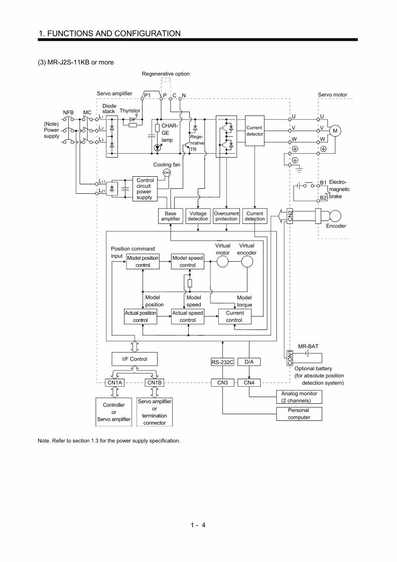
(3) MR-J2S-11KB or more
CN
2C
ON
1
CN1A CN1B
RS-232C D/A
L1
L2
L3
L11
L21
NFB MC
MR-BAT
P C
U
V
W
U
V
WM
B1
B2
NP1
CN3 CN4
Servo amplifier
Currentdetector
CHAR-GElamp Rege-
nrativeTR
Servo motor
Electro-magneticbrake
Encoder
Position commandinput Model position
controlModel speed
control
Virtualencoder
Virtualmotor
Modelposition
Modelspeed
Actual positioncontrol
Actual speedcontrol
Model torque
Currentcontrol
Optional battery(for absolute position detection system)
Analog monitor(2 channels)
Personal computer
Controlleror
Servo amplifier
Servo amplifieror
terminationconnector
I/F Control
Controlcircuitpowersupply
Currentdetection
Overcurrentprotection
Voltagedetection
Baseamplifier
Cooling fan
Diodestack Thyristor
(Note)Powersupply
Regenerative option
Note. Refer to section 1.3 for the power supply specification.
1 - 5
1. FUNCTIONS AND CONFIGURATION
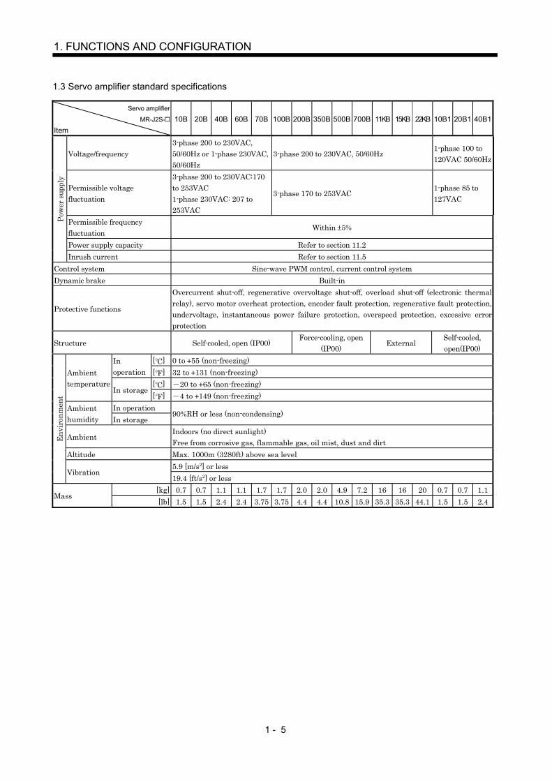
1.3 Servo amplifier standard specifications
Servo amplifier
MR-J2S-
Item10B 20B 40B 60B 70B 100B 200B 350B 500B 700B 11KB 15KB 22KB 10B1 20B1 40B1
Voltage/frequency3-phase 200 to 230VAC,50/60Hz or 1-phase 230VAC,50/60Hz
3-phase 200 to 230VAC, 50/60Hz1-phase 100 to120VAC 50/60Hz
Permissible voltagefluctuation
3-phase 200 to 230VAC:170to 253VAC1-phase 230VAC: 207 to253VAC
3-phase 170 to 253VAC1-phase 85 to127VAC
Permissible frequencyfluctuation
Within 5%
Power supply capacity Refer to section 11.2
Pow
er s
uppl
y
Inrush current Refer to section 11.5Control system Sine-wave PWM control, current control systemDynamic brake Built-in
Protective functions
Overcurrent shut-off, regenerative overvoltage shut-off, overload shut-off (electronic thermalrelay), servo motor overheat protection, encoder fault protection, regenerative fault protection,undervoltage, instantaneous power failure protection, overspeed protection, excessive errorprotection
Structure Self-cooled, open (IP00)Force-cooling, open
(IP00)External
Self-cooled,open(IP00)
[ ] 0 to 55 (non-freezing)Inoperation [ ] 32 to 131 (non-freezing)
[ ] 20 to 65 (non-freezing)Ambienttemperature
In storage[ ] 4 to 149 (non-freezing)
In operationAmbienthumidity In storage
90%RH or less (non-condensing)
AmbientIndoors (no direct sunlight)Free from corrosive gas, flammable gas, oil mist, dust and dirt
Altitude Max. 1000m (3280ft) above sea level5.9 [m/s2] or less
Envi
ronm
ent
Vibration19.4 [ft/s2] or less
[kg] 0.7 0.7 1.1 1.1 1.7 1.7 2.0 2.0 4.9 7.2 16 16 20 0.7 0.7 1.1Mass
[lb] 1.5 1.5 2.4 2.4 3.75 3.75 4.4 4.4 10.8 15.9 35.3 35.3 44.1 1.5 1.5 2.4

1 - 6
1. FUNCTIONS AND CONFIGURATION
1.4 Function list
The following table lists the functions of this servo. For details of the functions, refer to the reference field.Function Description Reference
High-resolution encoder High-resolution encoder of 131072 pulses/rev is used as a servo motor encoder.Absolute position detectionsystem
Merely setting a home position once makes home position return unnecessaryat every power-on.
Chapter 13
Adaptive vibrationsuppression control
Servo amplifier detects mechanical resonance and sets filter characteristicsautomatically to suppress mechanical vibration.
Section 7.3
Low-pass filterSuppresses high-frequency resonance which occurs as servo system response isincreased.
Section 7.4
Machine analyzer functionAnalyzes the frequency characteristic of the mechanical system by simplyconnecting a MR Configurator (servo configuration software)-installed personalcomputer and servo amplifier.
Machine simulationCan simulate machine motions on a personal computer screen on the basis ofthe machine analyzer results. The MR Configurator (servo configurationsoftware) is required.
Gain search functionPersonal computer changes gains automatically and searches for overshoot-free gains in a short time. The MR Configurator (servo configuration software)is required.
Slight vibration suppressioncontrol
Suppresses vibration of 1 pulse produced at a servo motor stop. Parameter No.24
Auto tuningAutomatically adjusts the gain to optimum value if load applied to the servomotor shaft varies. Higher in performance than MELSERVO-J2 series servoamplifier.
Chapter 6
Regenerative optionUsed when the built-in regenerative resistor of the servo amplifier does nothave sufficient regenerative capability for the regenerative power generated.
Section 12.1.1
Brake unitUsed when the regenerative option cannot provide enough regenerative power.Can be used with the MR-J2S-500B to MR-J2S-22KB.
Section 12.1.2
Return converterUsed when the regenerative option cannot provide enough regenerative power.Can be used with the MR-J2S-500B to MR-J2S-22KB.
Section 12.1.3
Torque limit Servo motor torque can be limited to any value.ParametersNo.10, 11
Forced stop signal automaticON
Forced stop (EM1) can be automatically switched on internally to invalidate it. Parameter No.23
Output signal (DO) forcedoutput
Output signal can be forced on/off independently of the servo status.Use this function for output signal wiring check, etc.
Section 4.4(1) (e)
Test operation mode JOG operation positioning operation motor-less operation DO forced output Section 4.4Analog monitor output Servo status is output in terms of voltage in real time. Parameter No. 22MR Configurator(Servo configuration software)
Using a personal computer, parameter setting, test operation, status display,etc. can be performed.
Section 12.1.8
1 - 7
1. FUNCTIONS AND CONFIGURATION
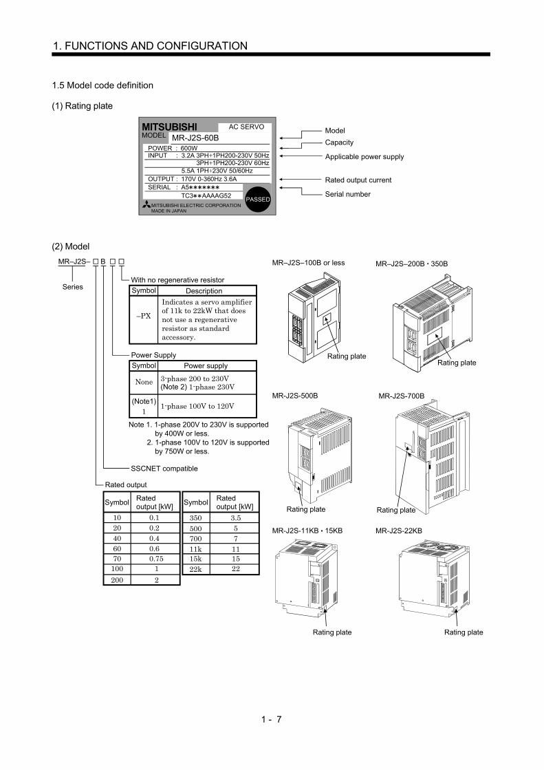
1.5 Model code definition
(1) Rating plate
POWER
MITSUBISHI AC SERVO
MADE IN JAPAN
MODEL MR-J2S-60B
MITSUBISHI ELECTRIC CORPORATION
600W 3.2A 3PH 1PH200-230V 50Hz
170V 0-360Hz 3.6A
POWER :INPUT :
OUTPUT : SERIAL :
AC SERVO
A5
PASSED
Model Capacity
Applicable power supply
Rated output current
Serial number
3PH 1PH200-230V 60Hz5.5A 1PH 230V 50/60Hz
TC3 AAAAG52
(2) Model
Indicates a servo amplifierof 11k to 22kW that does not use a regenerative resistor as standard accessory.
MR–J2S–
Series
B
SSCNET compatible
Power SupplyPower supply
None
(Note1)1
Symbol
Note 1. 1-phase 200V to 230V is supported by 400W or less. 2. 1-phase 100V to 120V is supported by 750W or less.
Rated output
Rated output [kW]
0.110
Symbol
0.2200.4400.6600.7570
11002200
3.5350
Rated output [kW]Symbol
55007700
11k15k22k
111522
Rating plate
MR–J2S–100B or less
Rating plateRating plate
MR–J2S–200B 350B
MR-J2S-500B MR-J2S-700B
Rating plate
MR-J2S-11KB 15KB MR-J2S-22KB
Rating plateRating plate
With no regenerative resistorDescription
–PX
Symbol
3-phase 200 to 230V(Note 2) 1-phase 230V
1-phase 100V to 120V
1 - 8
1. FUNCTIONS AND CONFIGURATION
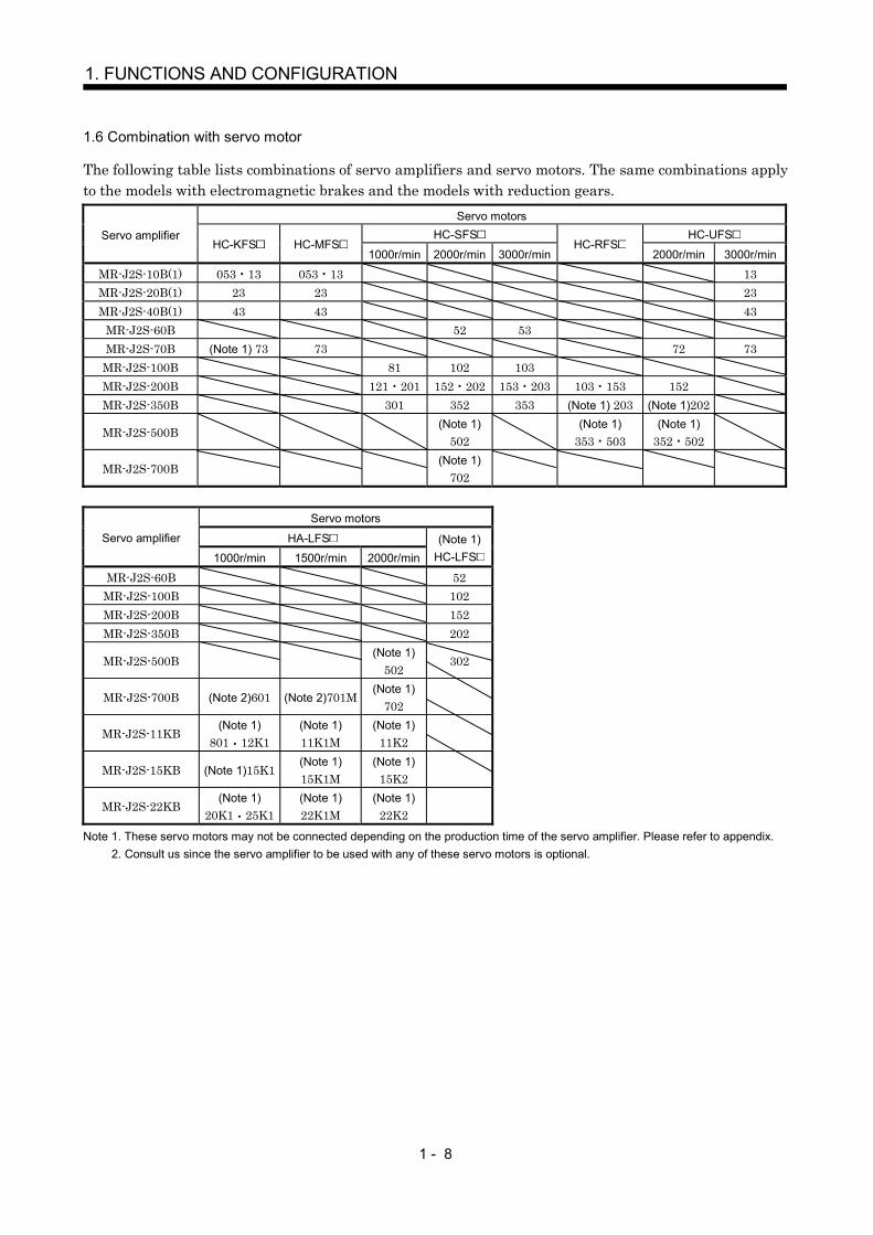
1.6 Combination with servo motor
The following table lists combinations of servo amplifiers and servo motors. The same combinations applyto the models with electromagnetic brakes and the models with reduction gears.
Servo motorsHC-SFS HC-UFSServo amplifier
HC-KFS HC-MFS1000r/min 2000r/min 3000r/min
HC-RFS2000r/min 3000r/min
MR-J2S-10B(1) 053 13 053 13 13MR-J2S-20B(1) 23 23 23MR-J2S-40B(1) 43 43 43
MR-J2S-60B 52 53MR-J2S-70B (Note 1) 73 73 72 73
MR-J2S-100B 81 102 103MR-J2S-200B 121 201 152 202 153 203 103 153 152MR-J2S-350B 301 352 353 (Note 1) 203 (Note 1)202
MR-J2S-500B(Note 1)
502(Note 1)
353 503(Note 1)
352 502
MR-J2S-700B(Note 1)
702
Servo motors
HA-LFSServo amplifier
1000r/min 1500r/min 2000r/min(Note 1)
HC-LFS
MR-J2S-60B 52MR-J2S-100B 102MR-J2S-200B 152MR-J2S-350B 202
MR-J2S-500B(Note 1)
502302
MR-J2S-700B (Note 2)601 (Note 2)701M(Note 1)
702
MR-J2S-11KB(Note 1)
801 12K1(Note 1)11K1M
(Note 1)11K2
MR-J2S-15KB (Note 1)15K1(Note 1)15K1M
(Note 1)15K2
MR-J2S-22KB(Note 1)
20K1 25K1(Note 1)22K1M
(Note 1)22K2
Note 1. These servo motors may not be connected depending on the production time of the servo amplifier. Please refer to appendix. 2. Consult us since the servo amplifier to be used with any of these servo motors is optional.

1 - 9
1. FUNCTIONS AND CONFIGURATION
1.7 Structure
1.7.1 Parts identification
(1) MR-J2S-100B or less
Reference
Section 13.3
Chapter 4
Name/Application
Battery holderContains the battery for absolute position data backup.
Battery connector (CON1)Used to connect the battery for absolute position data backup.
DisplayThe two-digit, seven-segment LED shows the servo status and alarm number.
Bus cable connector (CN1A)Used to connect the servo system controller or preceding axis servo amplifier.
Communication connector (CN3)Used to connect a personal computer (RS-232C) oroutput analog monitor data.
Charge lampLit to indicate that the main circuit is charged. Whilethis lamp is lit, do not reconnect the cables.
Encoder connector (CN2)Used to connect the servo motor encoder.
Main circuit terminal block (TE1) Used to connect the input power supply and servo motor.
Protective earth (PE) terminal ( )Ground terminal.
Section 13.3
Section 3.11
Section 3.2
Bus cable connector (CN1B)Used to connect the subsequent axis servo amplifier or termination connector (MR-A-TM).
Section 3.2
Section 3.2Section 12.1.5
Section 1.5
Section 3.2Section 12.1.5
Control circuit terminal block (TE2) Used to connect the control circuit power supply andregenerative option.
Section 3.5.2Section 10.1
Section 3.5.2Section 10.1
Section 12.1.1
Section 3.8Section 10.1
1
CB
987
54
3
0F
D
AB
CD
EF0123
45
6 7 8 9
Axis select switch (SW1)
Used to set the axis number of theservo amplifier.
SW1
Rating plate
1 - 10
1. FUNCTIONS AND CONFIGURATION
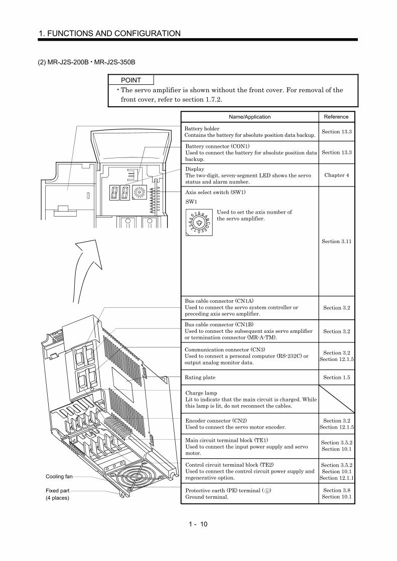
(2) MR-J2S-200B MR-J2S-350B
POINTThe servo amplifier is shown without the front cover. For removal of thefront cover, refer to section 1.7.2.
Reference
Section 13.3
Chapter 4
Name/Application
Battery holderContains the battery for absolute position data backup.
Battery connector (CON1)Used to connect the battery for absolute position data backup.
DisplayThe two-digit, seven-segment LED shows the servo status and alarm number.
Charge lampLit to indicate that the main circuit is charged. Whilethis lamp is lit, do not reconnect the cables.
Encoder connector (CN2)Used to connect the servo motor encoder.
Main circuit terminal block (TE1) Used to connect the input power supply and servo motor.
Protective earth (PE) terminal ( )Ground terminal.
Section 13.3
Axis select switch (SW1)
Section 3.11
Section 3.2
Section 3.2
Section 3.2Section 12.1.5
Section 1.5
Section 3.2Section 12.1.5
Control circuit terminal block (TE2) Used to connect the control circuit power supply andregenerative option.
Section 3.5.2Section 10.1
Section 3.5.2Section 10.1
Section 12.1.1
Section 3.8Section 10.1
Cooling fan
Fixed part(4 places)
AB
CD
EF0123
45
6 7 8 9
1
CB
987
54
3
0 F
D
SW1
Bus cable connector (CN1A)Used to connect the servo system controller or preceding axis servo amplifier.
Communication connector (CN3)Used to connect a personal computer (RS-232C) oroutput analog monitor data.
Bus cable connector (CN1B)Used to connect the subsequent axis servo amplifier or termination connector (MR-A-TM).
Used to set the axis number ofthe servo amplifier.
Rating plate

1 - 11
1. FUNCTIONS AND CONFIGURATION
(3) MR-J2S-500B
POINTThe servo amplifier is shown without the front cover. For removal of thefront cover, refer to section 1.7.2.
1
CB
987
54
3
0F
D
AB
CD
EF0123
45
6 7 8 9
Reference
Section 13.3
Name/Application
Battery holderContains the battery for absolute position data backup.
Battery connector (CON1)Used to connect the battery for absolute position data backup.
Section 13.3
Chapter 4DisplayThe two-digit, seven-segment LED shows the servo status and alarm number.
Section 3.11
Axis select switch (SW1)
Used to set the axis number of theservo amplifier.
SW1
Bus cable connector (CN1A)Used to connect the servo system controller or preceding axis servo amplifier.
Section 3.2
Bus cable connector (CN1B)Used to connect the subsequent axis servo amplifier or termination connector (MR-A-TM). Section 3.2
Communication connector (CN3)Used to connect a personal computer (RS-232C) oroutput analog monitor data.
Section 3.2Section 12.1.5
Charge lampLit to indicate that the main circuit is charged. Whilethis lamp is lit, do not reconnect the cables.
Encoder connector (CN2)Used to connect the servo motor encoder.
Section 3.2Section 12.1.5
Control circuit terminal block (TE2) Used to connect the control circuit power supply.
Section 3.5.2Section 10.1
Section 12.1.1
Main circuit terminal block (TE1) Used to connect the input power supply, regenerativeoption and servo motor.
Section 3.5.2Section 10.1
Section 1.5
Section 3.8Section 10.1
Protective earth (PE) terminal ( )Ground terminal.
Fixed part(4 places)
Cooling fanRating plate

1 - 12
1. FUNCTIONS AND CONFIGURATION
(4) MR-J2S-700B
POINTThe servo amplifier is shown without the front cover. For removal of thefront cover, refer to section 1.7.2.
AB
CD
EF0123
45
6 7 8 9
1
CB
987
54
3
0F
D
ReferenceName/Application
Battery connector (CON1)Used to connect the battery for absolute position data backup.
Section 13.3
Section 13.3Battery holderContains the battery for absolute position data backup.
Chapter 4DisplayThe two-digit, seven-segment LED shows the servo status and alarm number.
Section 3.11
Axis select switch (SW1)
Used to set the axis number of theservo amplifier.
SW1
Bus cable connector (CN1A)Used to connect the servo system controller or preceding axis servo amplifier. Section 3.2
Bus cable connector (CN1B)Used to connect the subsequent axis servo amplifier or termination connector (MR-A-TM). Section 3.2
Communication connector (CN3)Used to connect a personal computer (RS-232C) oroutput analog monitor data.
Section 3.2Section 12.1.5
Charge lampLit to indicate that the main circuit is charged. Whilethis lamp is lit, do not reconnect the cables.
Encoder connector (CN2)Used to connect the servo motor encoder. Section 3.2
Section 12.1.5
Control circuit terminal block (TE2) Used to connect the control circuit power supply.
Section 3.5.2Section 10.1
Section 12.1.1
Main circuit terminal block (TE1) Used to connect the input power supply, regenerativeoption and servo motor.
Section 3.5.2Section 10.1
Section 1.5
Section 3.8Section 10.1
Protective earth (PE) terminal ( )Ground terminal.
Cooling fan
Fixed part(4 places)
Rating plate

1 - 13
1. FUNCTIONS AND CONFIGURATION
(5) MR-J2S-11KB or more
POINTThe servo amplifier is shown without the front cover. For removal of thefront cover, refer to section 1.7.2.
Fixed part(4 places)
Cooling fan
Section 3.8Section 10.1
Reference
Chapter 4
Section 3.11
Section 3.2
Section 3.2Section 12.1.5
Section 1.5
Section 3.2Section 12.1.5
Section 3.5.2 Section 10.1
Section 3.5.2Section 10.1
Section 12.1.1
Section 13.3
Section 13.3
Section 3.2
Section 3.2Section 12.1.5
Section 3.2Section 12.1.5
Name/ApplicationAxis select switch (SW1)
1
C B A9 876543
20FED
SW1
Used to set the axis number ofthe servo amplifier.
DisplayThe two-digit, seven-segment LED shows the servo status and alarm number.
Battery holderContains the battery for absolute position data backup.
Battery connector (CON1)Used to connect the battery for absolute position data backup.
Communication connector (CN3)Used to connect a personal computer (RS-232C) .
Bus cable connector (CN1A)Used to connect the servo system controller or preceding axis servo amplifier.
Bus cable connector (CN1B)Used to connect the subsequent axis servo amplifier or termination connector (MR-A-TM).
Charge lampLit to indicate that the main circuit is charged. Whilethis lamp is lit, do not reconnect the cables.
Control circuit terminal block (TE2) Used to connect the control circuit power supply.
Encoder connector (CN2)Used to connect the servo motor encoder.
Rating plate
Main circuit terminal block (TE1) Used to connect the input power supply, regenerative option and servo motor.
Protective earth (PE) terminal ( )Ground terminal.
Monitor output terminal (CN4)Used to output monitor values on two channels in the form of analog signals.
I/O signal connector (CON2)Used to connect digital I/O signals.

1 - 14
1. FUNCTIONS AND CONFIGURATION
1.7.2 Removal and reinstallation of the front cover
CAUTION
Before removing or installing the front cover, turn off the power and wait for 15minutes or more until the charge lamp turns off. Then, confirm that the voltagebetween P and N is safe with a voltage tester and others. Otherwise, an electricshock may occur. In addition, always confirm from the front of the servo amplifierwhether the charge lamp is off or not.
(1) For MR-J2S-350B or less
Front cover hook (2 places)
Front cover socket (2 places)
2)
1)
Front cover
2)
1)
Removal of the front cover Reinstallation of the front cover
1) Insert the front cover hooks into the front cover sockets of the servo amplifier.2) Press the front cover against the servo amplifier until the removing knob clicks.
1) Hold down the removing knob.
2) Pull the front cover toward you.
(2) For MR-J2S-500B
Front cover socket (2 places)
Removal of the front cover Reinstallation of the front cover
1) Insert the front cover hooks into the front cover sockets of the servo amplifier.2) Press the front cover against the servo amplifier until the removing knob clicks.
1) Hold down the removing knob.
2) Pull the front cover toward you.
2)
1)
Front cover hook(2 places)
2)
1)
Front cover

1 - 15
1. FUNCTIONS AND CONFIGURATION
(3) For MR-J2S-700B
Front cover socket (2 places)
A)1)
Removal of the front cover Reinstallation of the front cover
1) Insert the two front cover hooks at the bottom into the sockets of the servo amplifier.2) Press the front cover against the servo amplifier until the removing knob clicks.
1) Push the removing knob A) or B), and put you finger into the front hole of the front cover.2) Pull the front cover toward you.
A)
2)
B)
2)
1)
Front coverhook (2 places)
(4) For MR-J2S-11KB or more
Mounting screws (2 places)
1) Remove the front cover mounting screws (2 places) and remove the front cover.
Removal of the front cover
Mounting screws(2 places)
2) Remove the front cover mounting screws (2 places).
3) Remove the front cover by drawing it in the direction of arrow.
1 - 16
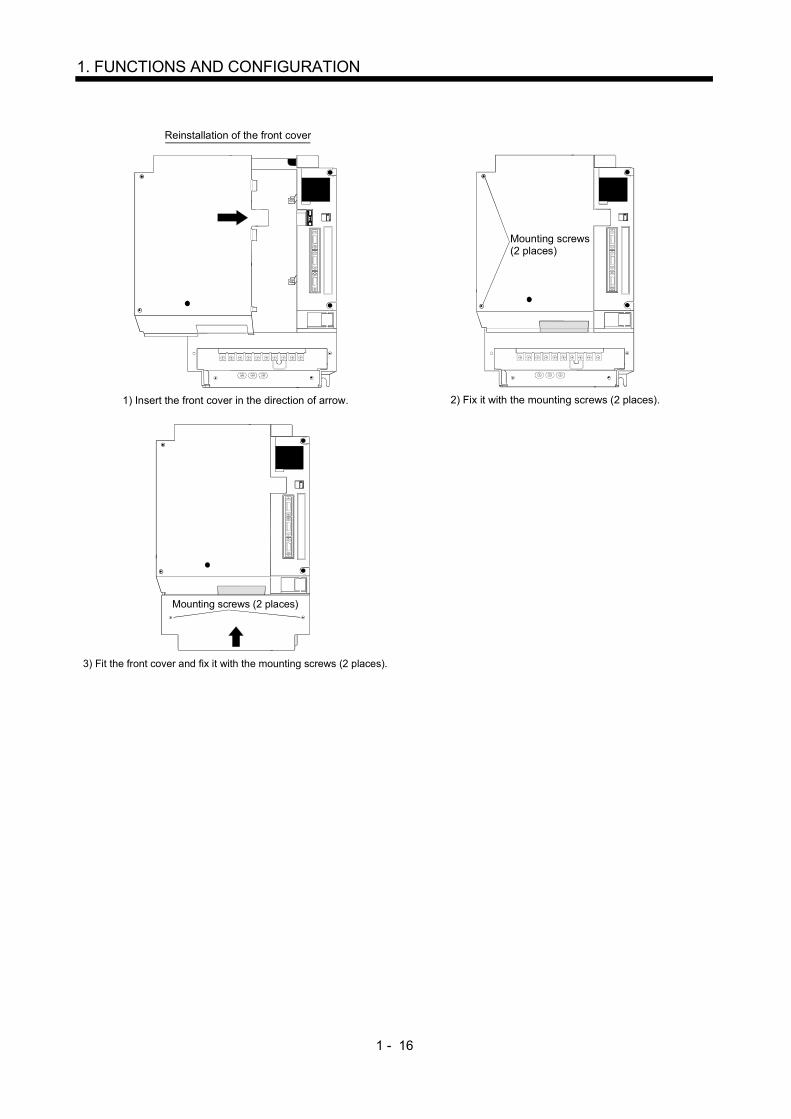
1. FUNCTIONS AND CONFIGURATION
1) Insert the front cover in the direction of arrow.
Reinstallation of the front cover
Mounting screws(2 places)
2) Fix it with the mounting screws (2 places).
Mounting screws (2 places)
3) Fit the front cover and fix it with the mounting screws (2 places).

1 - 17
1. FUNCTIONS AND CONFIGURATION
1.8 Servo system with auxiliary equipment
WARNING To prevent an electric shock, always connect the protective earth (PE) terminal ( )of the servo amplifier to the protective earth (PE) of the control box.
(1) MR-J2S-100B or less(a) For 3-phase 200V to 230V or 1-phase 230V
No-fuse breaker(NFB) or fuse
Magneticcontactor(MC)
To CN2
To CN3
To CN1B
To CN1A
Servo motor
Personalcomputer
MR Configurator(Servo configurationsoftwareMRZJW3-SETUP151E)
Servo amplifier
CHARGE
Options and auxiliary equipment
No-fuse breaker
Magnetic contactor
MR Configurator(Servo configuration software)
Regenerative option
Reference
Section 12.2.2
Section 12.2.2
Section 12.1.8
Section 12.1.1
Control circuit terminal block
Options and auxiliary equipment Reference
Cables Section 12.2.1
L1 L2 L3
L21 L11
U V W
D
P
C
Powerfactorimprovingreactor(FR-BAL)
Servo systemcontroller
orpreceding axisservo amplifier
CN1B
Subsequent axisservo amplifier
CN1Aor
Terminationconnector
Power factor improving reactor Section 12.2.3
(Note 2)Power supply
(Note 1)Encoder cable
(Note 1)Power supply lead
Regenerative option
Note 1. The HC-SFS, HC-RFS series have cannon connectors. 2. A 1-phase 230V power supply may be used with the servo amplifier of MR-J2S-70B or less. For 1-phase 230V, connect the
power supply to L1 L2 and leave L3 open. Refer to section 1.3 for the power supply specification.

1 - 18
1. FUNCTIONS AND CONFIGURATION
(b) For 1-phase 100V to 120V
L1 L2
L21
L11
U V W
D
P
C
No-fuse breaker(NFB) or fuse
Magneticcontactor(MC)
To CN2
To CN3
To CN1B
To CN1A
Servo motor
Personalcomputer
MR Configurator(Servo configurationsoftwareMRZJW3-SETUP151E)
Servo amplifier
CHARGE
Control circuit terminal block
Options and auxiliary equipment
No-fuse breaker
Magnetic contactor
MR Configurator(Servo configuration software)
Regenerative option
Reference
Section 12.2.2
Section 12.2.2
Section 12.1.8
Section 12.1.1
Options and auxiliary equipment Reference
Cables Section 12.2.1
Servo systemcontroller
orpreceding axisservo amplifier
CN1B
Subsequent axisservo amplifier
CN1Aor
Terminationconnector
Power factor improving reactor Section 12.2.3
Powerfactorimprovingreactor(FR-BAL)
(Note 1)Encoder cable
(Note 1)Power supply lead
(Note 2)Power supply
Regenerative option
Note 1. The HC-SFS, HC-RFS series have cannon connectors. 2. Refer to section 1.3 for the power supply specification.
1 - 19
1. FUNCTIONS AND CONFIGURATION
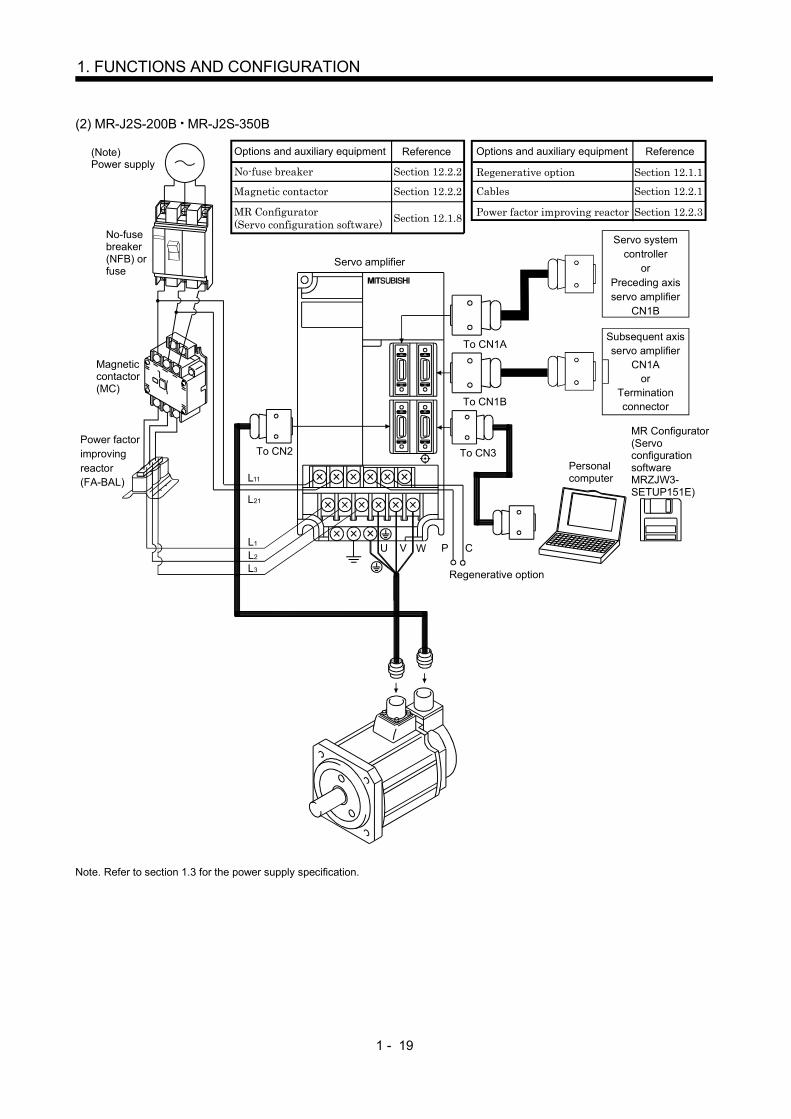
(2) MR-J2S-200B MR-J2S-350B
L1 L2 L3
L11
L21
U V W P C
No-fuse breaker(NFB) orfuse
Magneticcontactor(MC)
To CN3
To CN1B
To CN1A
Servo amplifier
Options and auxiliary equipment
No-fuse breaker
Magnetic contactor
MR Configurator(Servo configuration software)
Regenerative option
Reference
Section 12.2.2
Section 12.2.2
Section 12.1.8
Section 12.1.1
Options and auxiliary equipment Reference
Personalcomputer
MR Configurator(ServoconfigurationsoftwareMRZJW3-SETUP151E)
Cables Section 12.2.1
To CN2Power factorimprovingreactor(FA-BAL)
Power factor improving reactor Section 12.2.3
Servo systemcontroller
orPreceding axisservo amplifier
CN1B
Subsequent axisservo amplifier
CN1Aor
Terminationconnector
(Note)Power supply
Regenerative option
Note. Refer to section 1.3 for the power supply specification.

1 - 20
1. FUNCTIONS AND CONFIGURATION
(3) MR-J2S-500B
To CN1A
Options and auxiliary equipment
No-fuse breaker
Magnetic contactor
MR Configurator(Servo configuration software)
Regenerative option
Reference
Section 12.2.2
Section 12.2.2
Section 12.1.8
Section 12.1.1
Options and auxiliary equipment Reference
Cables Section 12.2.1
Power factor improving reactor Section 12.2.3No-fuse breaker(NFB) orfuse
Magneticcontactor(MC)
Powerfactorimprovingreactor(FA-BAL)
Servo amplifier
L1 L2 L3
C P
L11
L21
U VW
To CN1B
To CN3
To CN2
Servo systemcontroller
orPreceding axisservo amplifier
CN1B
Subsequent axisservo amplifier
CN1Aor
Terminationconnector
Personalcomputer
MRConfigurator(ServoconfigurationsoftwareMRZJW3-SETUP151E)
(Note 1)
(Note 2)Power supply
Regenerative option
Note 1. When using the regenerative option, remove the lead wires of the built-in regenerative resistor. 2. Refer to section 1.3 for the power supply specification.
1 - 21
1. FUNCTIONS AND CONFIGURATION
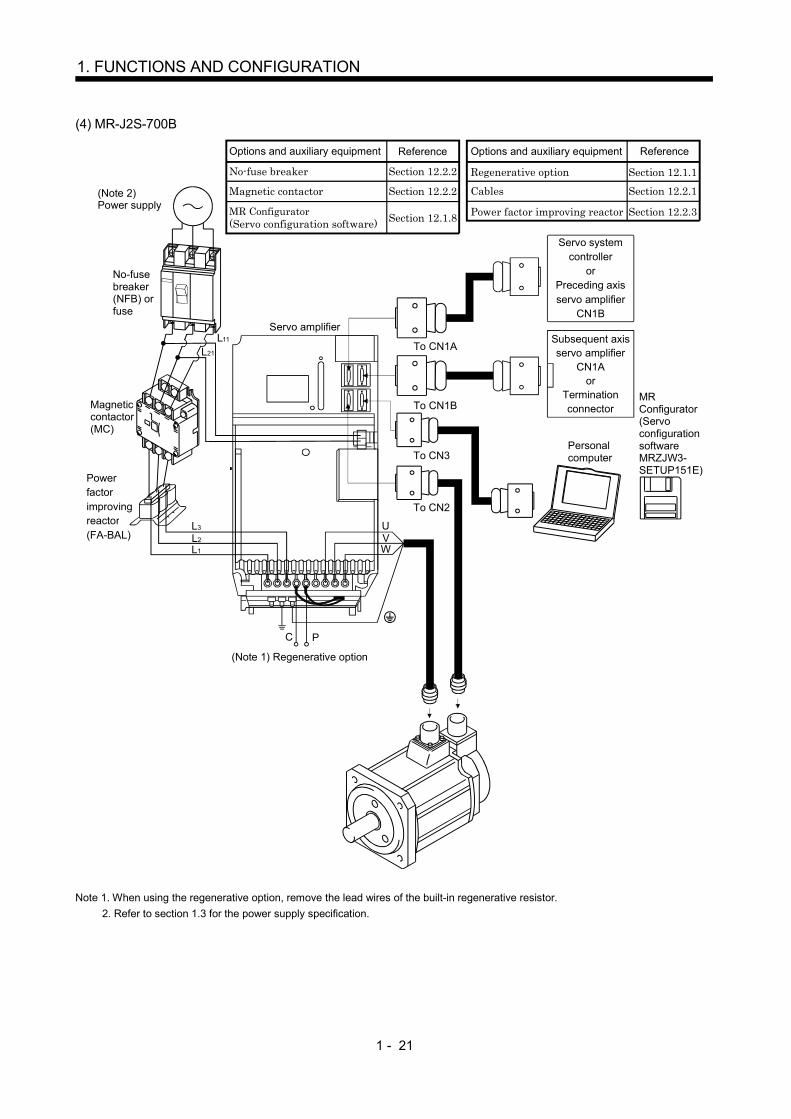
(4) MR-J2S-700B
WV
Options and auxiliary equipment
No-fuse breaker
Magnetic contactor
MR Configurator(Servo configuration software)
Regenerative option
Reference
Section 12.2.2
Section 12.2.2
Section 12.1.8
Section 12.1.1
Options and auxiliary equipment Reference
Cables Section 12.2.1
Power factor improving reactor Section 12.2.3
No-fuse breaker(NFB) orfuse
Magneticcontactor(MC)
Powerfactorimprovingreactor(FA-BAL)
L1
L2
L3 U
C P
Servo amplifier
To CN1A
To CN1B
To CN3
To CN2
Servo systemcontroller
orPreceding axisservo amplifier
CN1B
Subsequent axisservo amplifier
CN1Aor
Terminationconnector
Personalcomputer
MRConfigurator(ServoconfigurationsoftwareMRZJW3-SETUP151E)
L11
L21
(Note 1) Regenerative option
(Note 2)Power supply
Note 1. When using the regenerative option, remove the lead wires of the built-in regenerative resistor. 2. Refer to section 1.3 for the power supply specification.
1 - 22
1. FUNCTIONS AND CONFIGURATION
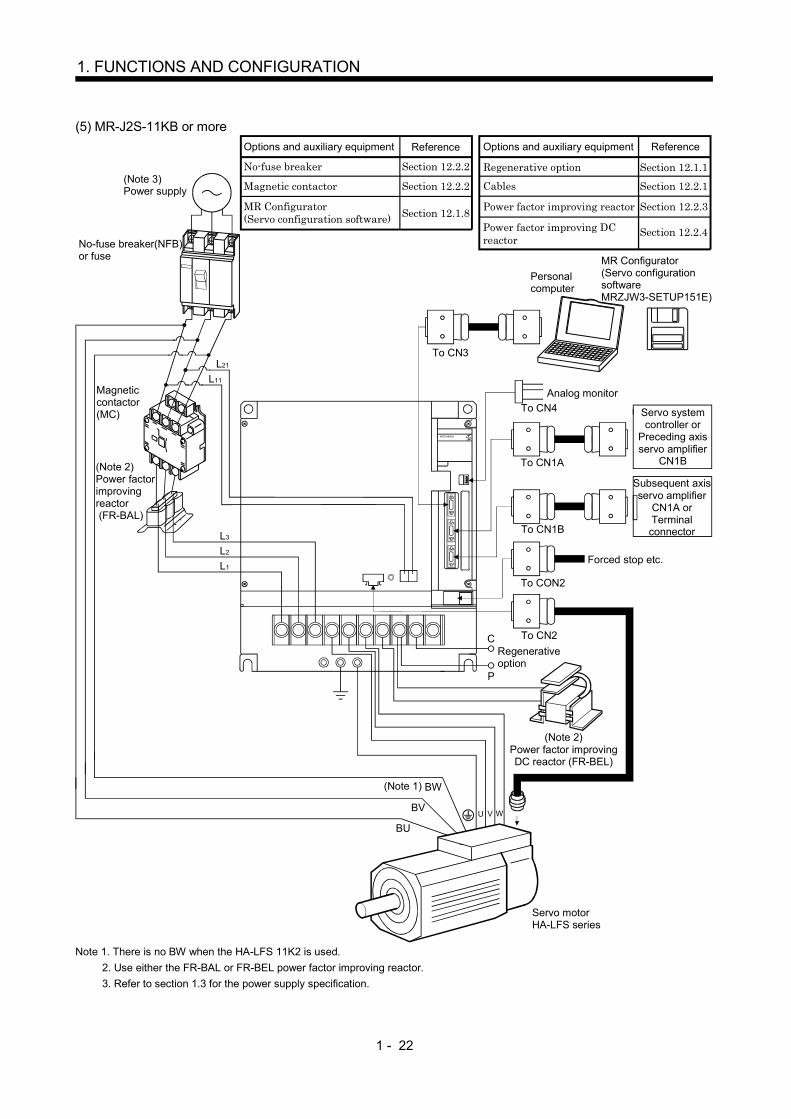
(5) MR-J2S-11KB or more
L11
L21
L2
L1
L3
To CN2
To CN1B
To CN1A
To CN3
MITSUBISHI
U V W
BW
C
P
To CON2
BV
BU
Options and auxiliary equipment
No-fuse breaker
Magnetic contactor
MR Configurator(Servo configuration software)
Regenerative option
Reference
Section 12.2.2
Section 12.2.2
Section 12.1.8
Section 12.1.1
Options and auxiliary equipment Reference
Cables Section 12.2.1
Power factor improving reactor Section 12.2.3
Section 12.2.4Power factor improving DC reactor
MR Configurator(Servo configuration softwareMRZJW3-SETUP151E)
Personal computer
To CN4Analog monitor
Servo system controller or
Preceding axis servo amplifier
CN1B
Subsequent axis servo amplifier
CN1A or Terminal connector
Forced stop etc.
Regenerative option
(Note 2)Power factor improving DC reactor (FR-BEL)
Servo motorHA-LFS series
(Note 2)Power factor improving reactor (FR-BAL)
Magnetic contactor(MC)
(Note 3)Power supply
No-fuse breaker(NFB)or fuse
(Note 1)
Note 1. There is no BW when the HA-LFS 11K2 is used. 2. Use either the FR-BAL or FR-BEL power factor improving reactor. 3. Refer to section 1.3 for the power supply specification.
2 - 1
2. INSTALLATION
2. INSTALLATION
CAUTION
Stacking in excess of the limited number of products is not allowed.
Install the equipment on incombustible material. Installing them directly or close tocombustibles will lead to a fire.
Install the equipment in a load-bearing place in accordance with this InstructionManual.
Do not get on or put heavy load on the equipment to prevent injury.
Use the equipment within the specified environmental condition range. (For theenvironmental conditions, refer to section 1.3.)
Provide an adequate protection to prevent screws, metallic detritus and otherconductive matter or oil and other combustible matter from entering the servoamplifier.
Do not block the intake/exhaust ports of the servo amplifier. Otherwise, a fault mayoccur.
Do not subject the servo amplifier to drop impact or shock loads as they areprecision equipment.
Do not install or operate a faulty servo amplifier.
When the product has been stored for an extended period of time, consultMitsubishi.
When treating the servo amplifier, be careful about the edged parts such as thecorners of the servo amplifier.
2.1 Environmental conditions
Environment Conditions
[ ] 0 to 55 (non-freezing)Inoperation [ ] 32 to 131 (non-freezing)
[ ] 20 to 65 (non-freezing)Ambienttemperature
In storage[ ] 4 to 149 (non-freezing)
In operationAmbienthumidity In storage
90%RH or less (non-condensing)
AmbienceIndoors (no direct sunlight)Free from corrosive gas, flammable gas, oil mist, dust and dirt
Altitude Max. 1000m (3280 ft) above sea level[m/s2] 5.9 [m/s2] or less
Vibration[ft/s2] 19.4 [ft/s2] or less

2 - 2
2. INSTALLATION
2.2 Installation direction and clearances
CAUTION
The equipment must be installed in the specified direction. Otherwise, a fault mayoccur.
Leave specified clearances between the servo amplifier and control box insidewalls or other equipment.
(1) Installation of one servo amplifierControl box Control box
10mm (0.4 in.) or more
10mm (0.4 in.) or more
40mm (1.6 in.) or moreServo amplifier
40mm (1.6 in.) or more
Wiring clearance 70mm (2.8 in.) Top
Bottom
2 - 3
2. INSTALLATION
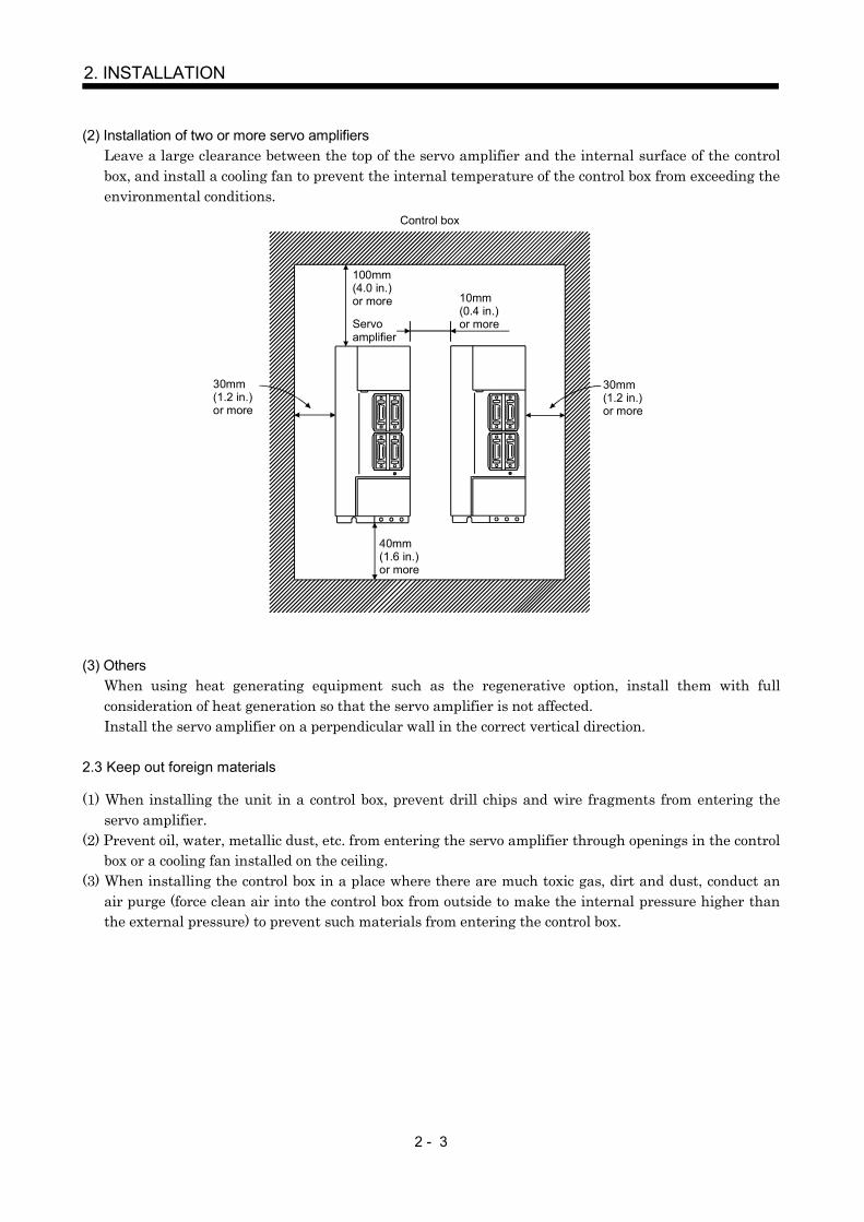
(2) Installation of two or more servo amplifiersLeave a large clearance between the top of the servo amplifier and the internal surface of the controlbox, and install a cooling fan to prevent the internal temperature of the control box from exceeding theenvironmental conditions.
Control box
30mm (1.2 in.) or more
30mm (1.2 in.) or more
10mm (0.4 in.) or more
40mm (1.6 in.) or more
100mm (4.0 in.) or more
Servoamplifier
(3) OthersWhen using heat generating equipment such as the regenerative option, install them with fullconsideration of heat generation so that the servo amplifier is not affected.Install the servo amplifier on a perpendicular wall in the correct vertical direction.
2.3 Keep out foreign materials
(1) When installing the unit in a control box, prevent drill chips and wire fragments from entering theservo amplifier.
(2) Prevent oil, water, metallic dust, etc. from entering the servo amplifier through openings in the controlbox or a cooling fan installed on the ceiling.
(3) When installing the control box in a place where there are much toxic gas, dirt and dust, conduct anair purge (force clean air into the control box from outside to make the internal pressure higher thanthe external pressure) to prevent such materials from entering the control box.

2 - 4
2. INSTALLATION
2.4 Cable stress
(1) The way of clamping the cable must be fully examined so that flexing stress and cable's own weightstress are not applied to the cable connection.
(2) For use in any application where the servo motor moves, fix the cables (encoder, power supply, brake)supplied with the servo motor, and flex the optional encoder cable or the power supply and brakewiring cables. Use the optional encoder cable within the flexing life range. Use the power supply andbrake wiring cables within the flexing life of the cables.
(3) Avoid any probability that the cable sheath might be cut by sharp chips, rubbed by a machine corneror stamped by workers or vehicles.
(4) For installation on a machine where the servo motor will move, the flexing radius should be made aslarge as possible. Refer to section 11.4 for the flexing life.

3 - 1
3. SIGNALS AND WIRING
3. SIGNALS AND WIRING
WARNING
Any person who is involved in wiring should be fully competent to do the work.
Before wiring, turn off the power and wait for 15 minutes or more until the chargelamp turns off. Then, confirm that the voltage between P and N is safe with avoltage tester and others. Otherwise, an electric shock may occur. In addition,always confirm from the front of the servo amplifier whether the charge lamp is offor not.
Ground the servo amplifier and the servo motor securely.
Do not attempt to wire the servo amplifier and servo motor until they have beeninstalled. Otherwise, you may get an electric shock.
The cables should not be damaged, stressed excessively, loaded heavily, orpinched. Otherwise, you may get an electric shock.
CAUTION
Wire the equipment correctly and securely. Otherwise, the servo motor maymisoperate, resulting in injury.
Connect cables to correct terminals to prevent a burst, fault, etc.
Ensure that polarity ( , ) is correct. Otherwise, a burst, damage, etc. may occur.
The surge absorbing diode installed to the DC relay designed for control outputshould be fitted in the specified direction. Otherwise, the signal is not output due toa fault, disabling the forced stop(EM1) and other protective circuits.
RA
COM(24VDC)
Controloutputsignal
Servoamplifier
Control output signal
COM(DC24V)
RA
Servoamplifier
Use a noise filter, etc. to minimize the influence of electromagnetic interference,which may be given to electronic equipment used near the servo amplifier.
Do not install a power capacitor, surge suppressor or radio noise filter (FR-BIFoption) with the power line of the servo motor.
When using the regenerative resistor, switch power off with the alarm signal.Otherwise, a transistor fault or the like may overheat the regenerative resistor,causing a fire.
Do not modify the equipment.
During power-on, do not open or close the motor power line. Otherwise, amalfunction or faulty may occur.
POINTCN1A, CN1B, CN2 and CN3 have the same shape. Wrong connection ofthe connectors will lead to a failure. Connect them correctly.

3 - 2
3. SIGNALS AND WIRING
3.1 Connection example of control signal system
POINTRefer to section 3.5 for the connection of the power supply system and tosection 3.6 for connection with the servo motor.
3.1.1 MR-J2S-700B or less
Servo amplifier
(Note 5)CN1A
CN1B(Note 5) SW1
CN1A
CN1B
CN1A
CN1B
CN1A
CN1B
MR-J2S-B(2 axis)
SW1
Setting: 1
SW1
(Note 11)
SW1
n
(Note 13)MR-A-TM
(Note 10, 14) Bus cable (Option)
(Note 1)
CN3
(Note 4)Personal computer
A
A
15m(49.2ft)or less
Encoder A-phase pulse(differential line driver)Encoder B-phase pulse(differential line driver)Encoder Z-phase pulse(differential line driver)
Plate2m(6.56ft) or less
(Note 3,4,7) Forced stop
10k
10k
Analog monitor outputMax. 1mAReading inboth directions
Magnetic brakeinterlock
Setting: 0
Servo system controller
Cable clamp(Option)
(Note 10, 14)Bus cable(Option)
MR-J2S-B(3 axis)
(Note 11)
Setting: 2
MR-J2S-B(n axis)
Setting: n 1
(Note 11)
(Note 12)1 to 8
(Note 2,6)
(Note15)
10 VDD
20 EM13 SG6 LA
16 LAR7 LB
17 LBR8 LZ
18 LZR
4 MO11 LG
14 MO211 LG
SD
10m(32.81ft) or lessCN3
(Note 5, 8)
13 MBR
5 COM
RA1
When using the forced stop (EM1) or magnetic brake interlock (MBR), make sure to connect it.
Control common
(Note 9)MR Configurator(Servo configurationsoftware)

3 - 3
3. SIGNALS AND WIRING
Note 1. To prevent an electric shock, always connect the protective earth (PE) terminal ( ) of the servo amplifier to the protectiveearth (PE) of the control box.
2. Connect the diode in the correct direction. If it is connected reversely, the servo amplifier will be faulty and will not outputsignals, disabling the forced stop (EM1) and other protective circuits.
3. If the controller does not have a forced stop function, always install a forced stop switch (Normally closed).4. When a personal computer is connected for use of the test operation mode, always use the maintenance junction card (MR-
J2CN3TM) to enable the use of the forced stop (EM1). (Refer to section 12.1.6)5. CN1A, CN1B, CN2 and CN3 have the same shape. Wrong connection of the connectors will lead to a fault.6. The sum of currents that flow in the external relays should be 80mA max.7. When starting operation, always turn on the forced stop (EM1). (Normally closed contacts) By setting “0001” in parameter
No.23, the forced stop (EM1) can be made invalid.8. When connecting the personal computer together with analog monitor outputs 1, 2, use the maintenance junction card (MR-
J2CN3TM). (Refer to section 12.1.3.)9. Use MRZJW3-SETUP151E.10. Use the bus cable at the overall distance of 30m(98.4ft) or less. In addition, to improve noise immunity, it is recommended to
use a cable clamp and data line filters (three or four filters connected in series) near the connector outlet.11. The wiring of the second and subsequent axes is omitted.12. Up to eight axes (n 1 to 8) may be connected. The MR-J2S- B/MR-J2-03B5 servo amplifier may be connected on the
same bus.13. Always insert the termination connector (MR-A-TM) into CN1B of the servo amplifier located at the termination.14. The bus cable used with the SSCNET depends on the preceding or subsequent controller or servo amplifier connected. Refer
to the following table and choose the bus cable.
MR-J2S- B MR-J2-03B5
QD75M MR-J2HBUS MQ172CPU(N) Q172J2BCBL M(-B)Q173CPU(N) Q173J2B CBL MMotion
controllerA motion MR-J2HBUS M-A
MR-J2S- B MR-J2-03B5Maintenance junction card
MR-J2HBUS M
15. When the A1SD75M (AD75M) is used as the controller, encoder pulses may not be output depending on the software version
of the controller. For details, refer to the A1SD75M (AD75M) Manual.

3 - 4
3. SIGNALS AND WIRING
3.1.2 MR-J2S-11KB or more
(Note 3, 6)CN3
CN1A
CN1B
10k
10k
SW1
Setting : 0
SW1
Setting : 2
SW1
Setting : 1
MR-J2S-B (2 axis)CN1A
CN1B
MR-J2S-B (3 axis)CN1A
CN1B
SW1
Setting: n-1
MR-J2S-B (n axis)CN1A
CN1Bn= 1 to 8
(Note 9)
(Note 10)
(Note 9)
(Note 9)
(Note 11)MR-A-TM
(Note 4)
(Note 4)
Magnetic brakeinterlock
Forced stop
(Note 2, 5)
Plate
Servo amplifier
(Note 4)
Cable clamp(Option)
(Note 8, 12)Bus cable (Option)
Servo system controller
(Note 1)
(Note 7)MR Configurator(Servo configurationsoftware)
Personal computer
15m(49.2ft)or less
(Note 8, 12) Bus cable (Option)
Analog monitor Max. 1mAReading inboth directions
2m(6.56ft) or less
Encoder A-phase pulse(differential line driver)
Encoder B-phase pulse(differential line driver)
Encoder Z-phase pulse(differential line driver)
(Note13)
Dynamic brake interlock
1
2
4
MO1
MO2
LG
CN4
2
1
4
EM1
SG
DB
CON2
3 MBR
18 COM
15 VDD
6
16
7
LA
LAR
LB
CN3
17
8
LBR
LZ
18 LZR
SD
LG
10m(32.81ft) or less
1
When using the forced stop (EM1), magnetic brake interlock (MBR) or dynamic brake interlock (DB), make sure to connect it.
RA1
RA2
A
A

3 - 5
3. SIGNALS AND WIRING
Note 1. To prevent an electric shock, always connect the protective earth (PE) terminal ( ) of the base unit to the protective earth(PE) of the control box.
2. Connect the diode in the correct direction. If it is connected reversely, the interface unit will be faulty and will not output signals,disabling the forced stop and other protective circuits.
3. If the controller does not have a forced stop (EM1) function, always install a forced stop switch (Normally closed).4. CN1A, CN1B, and CN3 have the same shape. Wrong connection of the connectors will lead to a fault.5. The sum of currents that flow in the external relays should be 80mA max.6. When starting operation, always turn on the forced stop (EM1). (Normally closed contacts) By setting “0001” in DRU parameter
No.23 of the drive unit, the forced stop (EM1) can be made invalid.7. Use MRZJW3-SETUP151E.8. Use the bus cable at the overall distance of 30m(98.4ft) or less. In addition, to improve noise immunity, it is recommended to
use a cable clamp and data line filters (three or four filters connected in series) near the connector outlet.9. The wiring of the second and subsequent axes is omitted.10. Up to eight axes (n 1 to 8) may be connected. The MR-J2S- B/MR-J2-03B5 servo amplifier may be connected on the
same bus.11. Always insert the termination connector (MR-A-TM) into CN1B of the interface unit located at the termination.12. The bus cable used with the SSCNET depends on the preceding or subsequent controller or servo amplifier connected. Refer
to the following table and choose the bus cable.
MR-J2S- B MR-J2-03B5
QD75M MR-J2HBUS MQ172CPU(N) Q172J2BCBL M(-B)Q173CPU(N) Q173J2B CBL MMotion
controllerA motion MR-J2HBUS M-A
MR-J2S- B MR-J2-03B5Maintenance junction card
MR-J2HBUS M
13. When the A1SD75M (AD75M) is used as the controller, encoder pulses may not be output depending on the software versionof the controller. For details, refer to the A1SD75M (AD75M) Manual.

3 - 6
3. SIGNALS AND WIRING
3.2 I/O signals
3.2.1 Connectors and signal arrangements
POINTThe pin configurations of the connectors are as viewed from the cableconnector wiring section.
(1) MR-J2S-700B or less
12
3
5
4
6
7
9
8
10
1112
1314
1516
1718
1920
RXD
MO1
VDD
LG
SG
COM
TXD
MO2
EM1
LG
MBR
12
3
5
4
6
7
9
8
10
1112
1314
1516
1718
1920
12
3
5
4
6
7
9
8
10
1112
1314
1516
1718
1920
12
3
5
4
6
7
9
8
10
1112
1314
1516
1718
1920
MD
LG
MDR
P5
LG
MRR
P5
LG
P5
BAT
MR
LG
MITSUBISHIMELSERVO-J2
CN2 CN3
CN1A CN1B
The connector frames are connected with the PE (earth) terminal inside the servo amplifier.
LG LGRD RD*
TD TD*
LG LG
EMG
BT
EMG*
LG LGRD RD*
TD TD*
LG LG
EMG
BT
EMG*
LA
LB
LAR
LBRLZRLZ

3 - 7
3. SIGNALS AND WIRING
(2) MR-J2S-11KB or more
2
RXD
4
6
LA
8
LZ
10
1
LG
3
5
7
LB
9
12
TXD
14
16
LAR
18
LZR
20
11
LG
13
15
17
LBR
19
CN3
CON2
2
EM1
4
6
8
10
1
SG
3
5
7
9
15
VDD
17
19
21
23
14
16
18
20
COM
22
12
MBR
11
13
2524
26
DB
MITSUBISHI
CHARGE
2
LG
4
6
MD
8
10
1
LG
3
5
7
MR
9
12
LG
14
16
MDR
18
P5
20
11
LG
13
15
17
MRR
19
P5P5BAT
CN2
CN1ASame as the one of the MR-J2S-700B or less.
CN1BSame as the one of the MR-J2S-700B or less.
CN4
1
2
4
MO1
MO2
LG
The connector frames are connected with the PE (earth) terminal inside the servo amplifier.
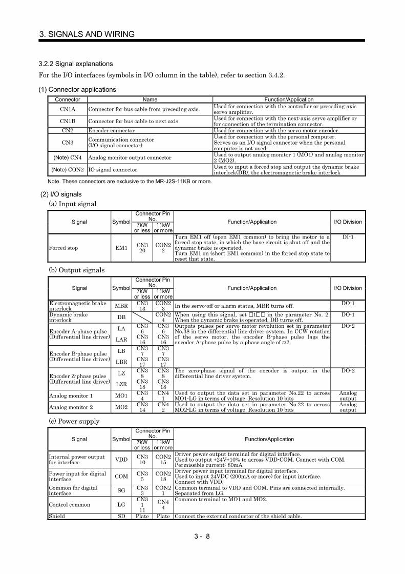
3 - 8
3. SIGNALS AND WIRING
3.2.2 Signal explanations
For the I/O interfaces (symbols in I/O column in the table), refer to section 3.4.2.
(1) Connector applicationsConnector Name Function/Application
CN1A Connector for bus cable from preceding axis. Used for connection with the controller or preceding-axisservo amplifier.
CN1B Connector for bus cable to next axis Used for connection with the next-axis servo amplifier orfor connection of the termination connector.
CN2 Encoder connector Used for connection with the servo motor encoder.
CN3 Communication connector(I/O signal connector)
Used for connection with the personal computer.Serves as an I/O signal connector when the personalcomputer is not used.
(Note) CN4 Analog monitor output connector Used to output analog monitor 1 (MO1) and analog monitor2 (MO2).
(Note) CON2 IO signal connector Used to input a forced stop and output the dynamic brakeinterlock(DB), the electromagnetic brake interlock
Note. These connectors are exclusive to the MR-J2S-11KB or more.
(2) I/O signals(a) Input signal
Connector PinNo.Signal Symbol 7kW
or less11kW
or moreFunction/Application I/O Division
Forced stop EM1 CN320
CON22
Turn EM1 off (open EM1 common) to bring the motor to aforced stop state, in which the base circuit is shut off and thedynamic brake is operated.Turn EM1 on (short EM1 common) in the forced stop state toreset that state.
DI-1
(b) Output signalsConnector Pin
No.Signal Symbol 7kWor less
11kWor more
Function/Application I/O Division
Electromagnetic brakeinterlock MBR CN3
13CON2
3 In the servo-off or alarm status, MBR turns off. DO-1
Dynamic brakeinterlock DB CON2
4When using this signal, set 1 in the parameter No. 2.When the dynamic brake is operated, DB turns off.
DO-1
Encoder A-phase pulse(Differential line driver)
LA
LAR
CN36
CN316
CN36
CN316
Encoder B-phase pulse(Differential line driver)
LB
LBR
CN37
CN317
CN37
CN317
Outputs pulses per servo motor revolution set in parameterNo.38 in the differential line driver system. In CCW rotationof the servo motor, the encoder B-phase pulse lags theencoder A-phase pulse by a phase angle of /2.
DO-2
Encoder Z-phase pulse(Differential line driver)
LZ
LZR
CN38
CN318
CN38
CN318
The zero-phase signal of the encoder is output in thedifferential line driver system.
DO-2
Analog monitor 1 MO1 CN34
CN41
Used to output the data set in parameter No.22 to acrossMO1-LG in terms of voltage. Resolution 10 bits
Analogoutput
Analog monitor 2 MO2 CN314
CN42
Used to output the data set in parameter No.22 to acrossMO2-LG in terms of voltage. Resolution 10 bits
Analogoutput
(c) Power supplyConnector Pin
No.Signal Symbol 7kWor less
11kWor more
Function/Application
Internal power outputfor interface VDD CN3
10CON2
15Driver power output terminal for digital interface.Used to output 24V 10% to across VDD-COM. Connect with COM.Permissible current: 80mA
Power input for digitalinterface COM CN3
5CON2
18Driver power input terminal for digital interface.Used to input 24VDC (200mA or more) for input interface.Connect with VDD.
Common for digitalinterface SG CN3
3CON2
1Common terminal to VDD and COM. Pins are connected internally.Separated from LG.
Control common LGCN3
111
CN44
Common terminal to MO1 and MO2.
Shield SD Plate Plate Connect the external conductor of the shield cable.

3 - 9
3. SIGNALS AND WIRING
3.3 Alarm occurrence timing chart
CAUTION
When an alarm has occurred, remove its cause, make sure that the operationsignal is not being input, ensure safety, and reset the alarm before restartingoperation.
As soon as an alarm occurs, make the Servo off status and interrupt the maincircuit power.
When an alarm occurs in the servo amplifier, the base circuit is shut off and the servo motor is coated to astop. Switch off the main circuit power supply in the external sequence. To deactivate the alarm, powerthe control circuit off, then on or give the error reset or CPU reset command from the servo systemcontroller. However, the alarm cannot be deactivated unless its cause is removed.
ONOFFON
OFF
ONOFF
NO YES
ONOFF
1sNO YES
Main circuitControl circuit
power
Base circuit
Dynamic brake
Servo-on command(from controller)
Alarm
Reset command(from controller)
ValidInvalid
Alarm occurs. Remove cause of trouble.50ms or more 60ms or more
NO
Brake operation Brake operation
Power onPower off
(Note)
Note. Switch off the main circuit power as soon as an alarm occurs.
(1) Overcurrent, overload 1 or overload 2If operation is repeated by switching control circuit power off, then on to reset the overcurrent (32),overload 1 (50) or overload 2 (51) alarm after its occurrence, without removing its cause, the servoamplifier and servo motor may become faulty due to temperature rise. Securely remove the cause ofthe alarm and also allow about 30 minutes for cooling before resuming operation.
(2) Regenerative alarmIf operation is repeated by switching control circuit power off, then on to reset the regenerative (30)alarm after its occurrence, the external regenerative resistor will generate heat, resulting in anaccident.
(3) Instantaneous power failureUndervoltage (10) occurs when the input power is in either of the following statuses.
A power failure of the control circuit power supply continues for 60ms or longer and the controlcircuit is not completely off.The bus voltage dropped to 200VDC or less for the MR-J2S B, or to 158VDC or less for the MR-J2SB1.

3 - 10
3. SIGNALS AND WIRING
3.4 Interfaces
3.4.1 Common line
The following diagram shows the power supply and its common line.To conform to the EMC directive, refer to the EMC Installation Guide lines (IB(NA)67310).
EM1
SG
MR
MRR
SDM
DI-1
COMVDD
LGSD
CN2
LG
RS-232C
LG
RA
Servo amplifier
24VDC
MBR
<Isolated>
LA .etcLAR .etc
MO1MO2
TXD
RXD
Ground
Servo motor
Differential linedriver output35mA max.
Analog monitor output
Servo motor encoder
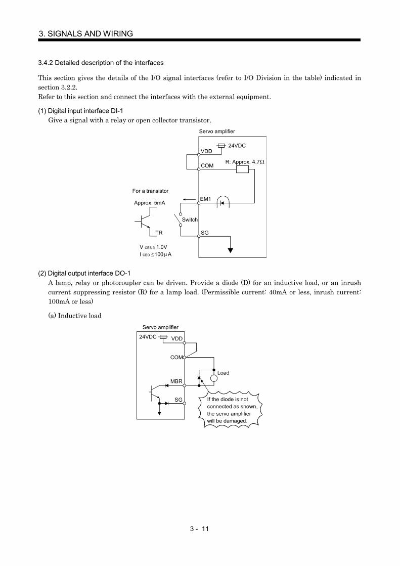
3 - 11
3. SIGNALS AND WIRING
3.4.2 Detailed description of the interfaces
This section gives the details of the I/O signal interfaces (refer to I/O Division in the table) indicated insection 3.2.2.Refer to this section and connect the interfaces with the external equipment.
(1) Digital input interface DI-1Give a signal with a relay or open collector transistor.
VDD
COM
24VDC
SGTR
Servo amplifier
R: Approx. 4.7
EM1For a transistor
Approx. 5mA
V CES 1.0VI CEO 100 A
Switch
(2) Digital output interface DO-1A lamp, relay or photocoupler can be driven. Provide a diode (D) for an inductive load, or an inrushcurrent suppressing resistor (R) for a lamp load. (Permissible current: 40mA or less, inrush current:100mA or less)
(a) Inductive load
VDD24VDC
COM
SG If the diode is notconnected as shown,the servo amplifierwill be damaged.
LoadMBR
Servo amplifier

3 - 12
3. SIGNALS AND WIRING
(b) Lamp load
24VDC VDD
COM
R
MBR
SG
Servo amplifier
(3) Encoder pulse output DO-2(Differential line driver system)1) Interface
Max. output current: 35mA
LA(LB, LZ)
LAR(LBR, LZR)
LG
SD
LA(LB, LZ)
LAR(LBR, LZR)
SD
Servo amplifier Servo amplifier
Am26LS32 or equivalent High-speed photocoupler
150
100
2) Pulse outputServo motor CCW rotation
LA
LAR
LB
LBR
LZLZR
T
/2
400 s or more
Time cycle (T) is determined by the settings of parameter No.33 and 38.

3 - 13
3. SIGNALS AND WIRING
(4) Analog outputOutput voltage : 10VMax. output current :1mAResolution :10bit
MO1(MO2)
LG
SD
A
Servo amplifier
Reading in one orboth directions1mA meter
10k
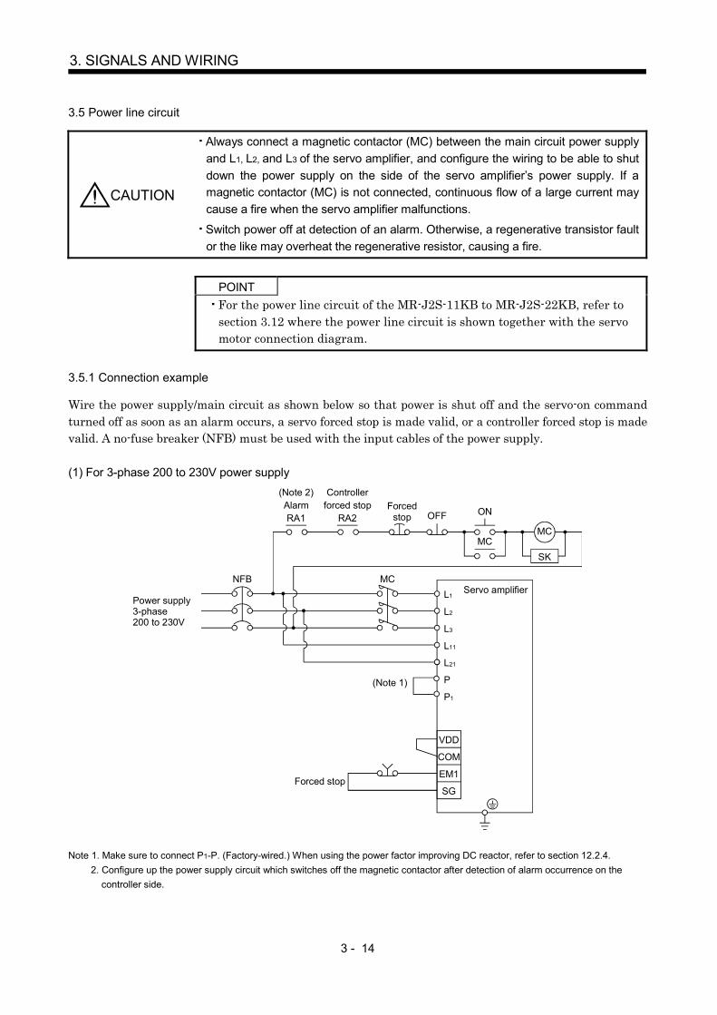
3 - 14
3. SIGNALS AND WIRING
3.5 Power line circuit
CAUTION
Always connect a magnetic contactor (MC) between the main circuit power supplyand L1, L2, and L3 of the servo amplifier, and configure the wiring to be able to shutdown the power supply on the side of the servo amplifier’s power supply. If amagnetic contactor (MC) is not connected, continuous flow of a large current maycause a fire when the servo amplifier malfunctions.
Switch power off at detection of an alarm. Otherwise, a regenerative transistor faultor the like may overheat the regenerative resistor, causing a fire.
POINTFor the power line circuit of the MR-J2S-11KB to MR-J2S-22KB, refer tosection 3.12 where the power line circuit is shown together with the servomotor connection diagram.
3.5.1 Connection example
Wire the power supply/main circuit as shown below so that power is shut off and the servo-on commandturned off as soon as an alarm occurs, a servo forced stop is made valid, or a controller forced stop is madevalid. A no-fuse breaker (NFB) must be used with the input cables of the power supply.
(1) For 3-phase 200 to 230V power supply
EM1
COM
OFF ON
MCMC
SK
NFB MCL1
L2
L3
L11
L21
VDD
SG
(Note 2)AlarmRA1
Controllerforced stop
RA2Forced
stop
Servo amplifier
Forced stop
(Note 1) P
P1
Power supply3-phase200 to 230V
Note 1. Make sure to connect P1-P. (Factory-wired.) When using the power factor improving DC reactor, refer to section 12.2.4.2. Configure up the power supply circuit which switches off the magnetic contactor after detection of alarm occurrence on the
controller side.

3 - 15
3. SIGNALS AND WIRING
(2) For 1-phase 100 to 120V or 1-phase 230V power supply
EM1
COM
OFF ON
MCMC
SK
NFB MCL1
L2
L3
L11
L21
VDD
SG
(Note 1)AlarmRA1
Controller forced stop
RA2Forced
stop
Servo amplifier
Forced stop
(Note 2)
Power supply1-phase 100 to 120V or 1-phase 230V
Note 1. Configure up the power supply circuit which switches off the magnetic contactor after detection of alarm occurrence on thecontroller side.
2. Not provided for 1-phase 100 to 120V.
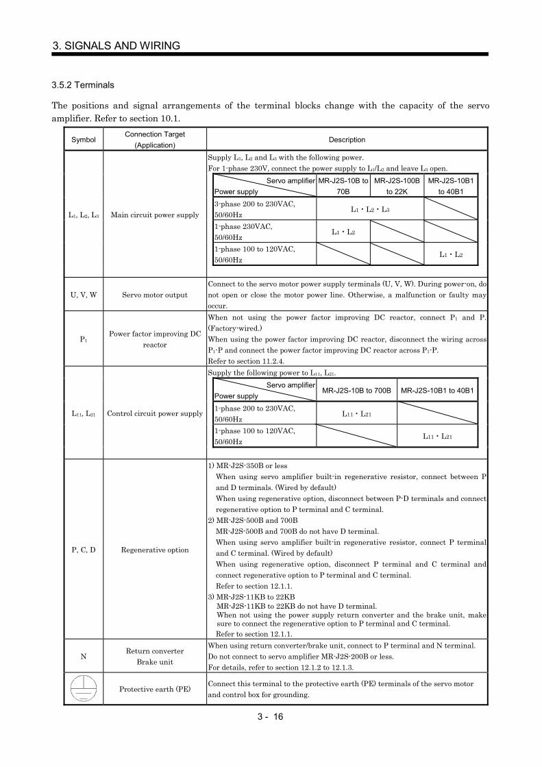
3 - 16
3. SIGNALS AND WIRING
3.5.2 Terminals
The positions and signal arrangements of the terminal blocks change with the capacity of the servoamplifier. Refer to section 10.1.
SymbolConnection Target
(Application)Description
Supply L1, L2 and L3 with the following power.For 1-phase 230V, connect the power supply to L1/L2 and leave L3 open.
Servo amplifierPower supply
MR-J2S-10B to70B
MR-J2S-100Bto 22K
MR-J2S-10B1to 40B1
3-phase 200 to 230VAC,50/60Hz
L1 L2 L3
1-phase 230VAC,50/60Hz
L1 L2
1-phase 100 to 120VAC,50/60Hz
L1 L2
L1, L2, L3 Main circuit power supply
U, V, W Servo motor outputConnect to the servo motor power supply terminals (U, V, W). During power-on, donot open or close the motor power line. Otherwise, a malfunction or faulty mayoccur.
P1Power factor improving DC
reactor
When not using the power factor improving DC reactor, connect P1 and P.(Factory-wired.)When using the power factor improving DC reactor, disconnect the wiring acrossP1-P and connect the power factor improving DC reactor across P1-P.Refer to section 11.2.4.Supply the following power to L11, L21.
Servo amplifierPower supply
MR-J2S-10B to 700B MR-J2S-10B1 to 40B1
1-phase 200 to 230VAC,50/60Hz
L11 L21
1-phase 100 to 120VAC,50/60Hz
L11 L21
L11, L21 Control circuit power supply
P, C, D Regenerative option
1) MR-J2S-350B or lessWhen using servo amplifier built-in regenerative resistor, connect between Pand D terminals. (Wired by default)When using regenerative option, disconnect between P-D terminals and connectregenerative option to P terminal and C terminal.
2) MR-J2S-500B and 700BMR-J2S-500B and 700B do not have D terminal.When using servo amplifier built-in regenerative resistor, connect P terminaland C terminal. (Wired by default)When using regenerative option, disconnect P terminal and C terminal andconnect regenerative option to P terminal and C terminal.Refer to section 12.1.1.
3) MR-J2S-11KB to 22KBMR-J2S-11KB to 22KB do not have D terminal.When not using the power supply return converter and the brake unit, makesure to connect the regenerative option to P terminal and C terminal.Refer to section 12.1.1.
NReturn converter
Brake unit
When using return converter/brake unit, connect to P terminal and N terminal.Do not connect to servo amplifier MR-J2S-200B or less.For details, refer to section 12.1.2 to 12.1.3.
Protective earth (PE)Connect this terminal to the protective earth (PE) terminals of the servo motorand control box for grounding.
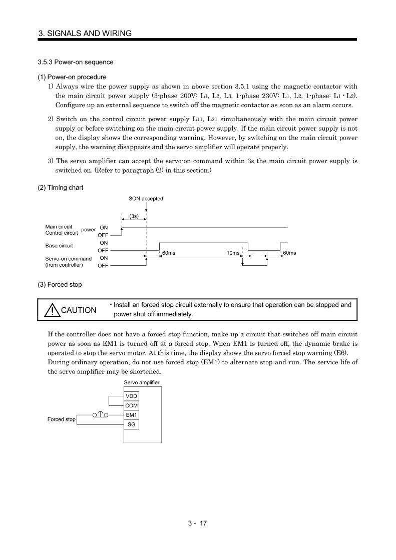
3 - 17
3. SIGNALS AND WIRING
3.5.3 Power-on sequence
(1) Power-on procedure1) Always wire the power supply as shown in above section 3.5.1 using the magnetic contactor with
the main circuit power supply (3-phase 200V: L1, L2, L3, 1-phase 230V: L1, L2, 1-phase: L1 L2).Configure up an external sequence to switch off the magnetic contactor as soon as an alarm occurs.
2) Switch on the control circuit power supply L11, L21 simultaneously with the main circuit powersupply or before switching on the main circuit power supply. If the main circuit power supply is noton, the display shows the corresponding warning. However, by switching on the main circuit powersupply, the warning disappears and the servo amplifier will operate properly.
3) The servo amplifier can accept the servo-on command within 3s the main circuit power supply isswitched on. (Refer to paragraph (2) in this section.)
(2) Timing chart
(3s)
ONOFFON
OFFON
OFF
10ms 60ms60msBase circuit
Servo-on command(from controller)
SON accepted
Main circuitControl circuit power
(3) Forced stop
CAUTIONInstall an forced stop circuit externally to ensure that operation can be stopped andpower shut off immediately.
If the controller does not have a forced stop function, make up a circuit that switches off main circuitpower as soon as EM1 is turned off at a forced stop. When EM1 is turned off, the dynamic brake isoperated to stop the servo motor. At this time, the display shows the servo forced stop warning (E6).During ordinary operation, do not use forced stop (EM1) to alternate stop and run. The service life ofthe servo amplifier may be shortened.
Servo amplifier
EM1
SG
VDD
COM
Forced stop
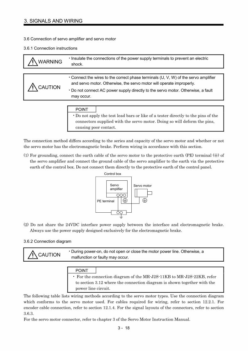
3 - 18
3. SIGNALS AND WIRING
3.6 Connection of servo amplifier and servo motor
3.6.1 Connection instructions
WARNINGInsulate the connections of the power supply terminals to prevent an electricshock.
CAUTION
Connect the wires to the correct phase terminals (U, V, W) of the servo amplifierand servo motor. Otherwise, the servo motor will operate improperly.
Do not connect AC power supply directly to the servo motor. Otherwise, a faultmay occur.
POINTDo not apply the test lead bars or like of a tester directly to the pins of theconnectors supplied with the servo motor. Doing so will deform the pins,causing poor contact.
The connection method differs according to the series and capacity of the servo motor and whether or notthe servo motor has the electromagnetic brake. Perform wiring in accordance with this section.
(1) For grounding, connect the earth cable of the servo motor to the protective earth (PE) terminal ( ) ofthe servo amplifier and connect the ground cable of the servo amplifier to the earth via the protectiveearth of the control box. Do not connect them directly to the protective earth of the control panel.
Servoamplifier
Servo motor
PE terminal
Control box
(2) Do not share the 24VDC interface power supply between the interface and electromagnetic brake.Always use the power supply designed exclusively for the electromagnetic brake.
3.6.2 Connection diagram
CAUTIONDuring power-on, do not open or close the motor power line. Otherwise, amalfunction or faulty may occur.
POINT For the connection diagram of the MR-J2S-11KB to MR-J2S-22KB, referto section 3.12 where the connection diagram is shown together with thepower line circuit.
The following table lists wiring methods according to the servo motor types. Use the connection diagramwhich conforms to the servo motor used. For cables required for wiring, refer to section 12.2.1. Forencoder cable connection, refer to section 12.1.4. For the signal layouts of the connectors, refer to section3.6.3.For the servo motor connector, refer to chapter 3 of the Servo Motor Instruction Manual.
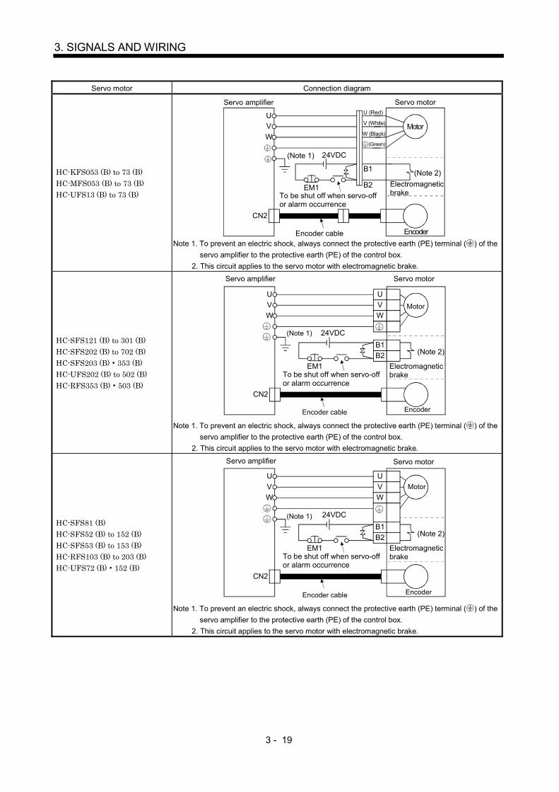
3 - 19
3. SIGNALS AND WIRING
Servo motor Connection diagram
HC-KFS053 (B) to 73 (B)HC-MFS053 (B) to 73 (B)HC-UFS13 (B) to 73 (B)
Servo amplifier
(Note 1)
Servo motor
Electromagnetic brake
24VDC
EM1
(Note 2)
To be shut off when servo-off or alarm occurrence
Encoder cable
CN2
Motor
Encoder
UVW
B1
B2
U (Red)
V (White)
W (Black)
(Green)
Note 1. To prevent an electric shock, always connect the protective earth (PE) terminal ( ) of theservo amplifier to the protective earth (PE) of the control box.
2. This circuit applies to the servo motor with electromagnetic brake.
HC-SFS121 (B) to 301 (B)HC-SFS202 (B) to 702 (B)HC-SFS203 (B) 353 (B)HC-UFS202 (B) to 502 (B)HC-RFS353 (B) 503 (B)
Electromagnetic brake
(Note 2)
To be shut off when servo-off or alarm occurrence
24VDC
EM1
CN2
UVW
UVW
B1B2
Servo amplifier
(Note 1)
EncoderEncoder cable
Motor
Servo motor
Note 1. To prevent an electric shock, always connect the protective earth (PE) terminal ( ) of theservo amplifier to the protective earth (PE) of the control box.
2. This circuit applies to the servo motor with electromagnetic brake.
HC-SFS81 (B)HC-SFS52 (B) to 152 (B)HC-SFS53 (B) to 153 (B)HC-RFS103 (B) to 203 (B)HC-UFS72 (B) 152 (B)
Electromagnetic brake
(Note 2)
To be shut off when servo-off or alarm occurrence
24VDC
EM1
CN2
UVW
UVW
B1B2
Servo amplifier
(Note 1)
EncoderEncoder cable
Motor
Servo motor
Note 1. To prevent an electric shock, always connect the protective earth (PE) terminal ( ) of theservo amplifier to the protective earth (PE) of the control box.
2. This circuit applies to the servo motor with electromagnetic brake.

3 - 20
3. SIGNALS AND WIRING
3.6.3 I/O terminals
(1) HC-KFS HC-MFS HC-UFS3000r/min series
2 4
1 3
4
Power supply connector (Molex)Without electromagnetic brake5557-04R-210 (receptacle)5556PBTL (Female terminal)With electromagnetic brake5557-06R-210 (receptacle)5556PBTL (Female terminal)
Encoder cable 0.3m (0.98ft.)
Power supply lead4-AWG19 0.3m (0.98ft.)
With connector 1-172169-9(Tyco Electronics)
1234
1
2 5
4
3 6
123
56
Power supplyconnector5557-04R-210 Pin Signal
UVW
Power supplyconnector5557-06R-210
Pin Signal
(Earth)
UVW
MR
1 2 3
MRR BAT
MD
4 5 6
MDR
P5
7 8 9
LG SHD
Encoder connector signal arrangement
B1B2
(Note)(Note)
Note. For the motor with electromagnetic brake, supply electromagnetic brake power (24VDC). There is no polarity.
a
b
View b
View b
View a
(Earth)
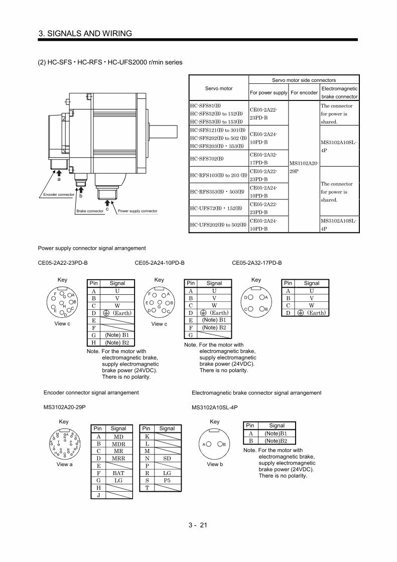
3 - 21
3. SIGNALS AND WIRING
(2) HC-SFS HC-RFS HC-UFS2000 r/min series
Servo motor side connectorsServo motor
For power supply For encoderElectromagneticbrake connector
HC-SFS81(B)HC-SFS52(B) to 152(B)HC-SFS53(B) to 153(B)
CE05-2A22-23PD-B
The connectorfor power isshared.
HC-SFS121(B) to 301(B)HC-SFS202(B) to 502 (B)HC-SFS203(B) 353(B)
CE05-2A24-10PD-B
HC-SFS702(B)CE05-2A32-17PD-B
MS3102A10SL-4P
HC-RFS103(B) to 203 (B)CE05-2A22-23PD-B
HC-RFS353(B) 503(B)CE05-2A24-10PD-B
HC-UFS72(B) 152(B)CE05-2A22-23PD-B
The connectorfor power isshared.
Encoder connector
Brake connector Power supply connector
a
b
c
HC-UFS202(B) to 502(B)CE05-2A24-10PD-B
MS3102A20-29P
MS3102A10SL-4P
PinABCDEFGH
SignalUVW
(Note) B2
(Earth)
Key
(Note) B1
CE05-2A22-23PD-B
Power supply connector signal arrangement
PinABCDEFG
UVW
CE05-2A24-10PD-B
Signal
(Earth)
(Note) B2(Note) B1
Note. For the motor with electromagnetic brake, supply electromagnetic brake power (24VDC). There is no polarity.
View c View c
D
C B
AA
BC
DE
FG
H
A
B
CD
E
F
G
PinABCD
UVW
Signal
(Earth)
Key Key
CE05-2A32-17PD-B
Note. For the motor with electromagnetic brake, supply electromagnetic brake power (24VDC). There is no polarity.
Pin ABCDEFGHJ
Signal
MR MRR
BAT LG
Pin KLMNPRST
Signal
SD
LG P5
Encoder connector signal arrangement
MS3102A20-29P
Key
MD MDR
FView a
Pin AB
Signal(Note)B1 (Note)B2
Electromagnetic brake connector signal arrangement
MS3102A10SL-4P
Key
View b
A
GH F
J EK D
LM B
CN
S R
T PA B
Note. For the motor with electromagnetic brake, supply electromagnetic brake power (24VDC). There is no polarity.

3 - 22
3. SIGNALS AND WIRING
3.7 Servo motor with electromagnetic brake
CAUTION
Configure the electromagnetic brake circuit so that it is activated not only by theinterface unit signals but also by a forced stop (EM1).
EM1RA
24VDC
Contacts must be open whenservo-off, when an alarm occurrenceand when an electromagnetic brake interlock (MBR).
Electromagnetic brake
Servo motor
Circuit must be opened duringforced stop (EM1).
The electromagnetic brake is provided for holding purpose and must not be usedfor ordinary braking.
Before performing the operation, be sure to confirm that the electromagnetic brakeoperates properly.
POINTRefer to the Servo Motor Instruction Manual for specifications such as thepower supply capacity and operation delay time of the electromagneticbrake.
Note the following when the servo motor equipped with electromagnetic brake is used.
1) Do not share the 24VDC interface power supply between the interface and electromagneticbrake. Always use the power supply designed exclusively for the electromagnetic brake.
2) The brake will operate when the power (24VDC) switches off.
3) Switch off the servo-on command after the servo motor has stopped.
(1) Connection diagram
MBR
COM
Servo amplifier Servo motor
B1
B2
ForcedstopRA
24VDC
RA
VDD
(2) SettingIn parameter No.21 (electromagnetic brake sequence output), set the time delay (Tb) fromelectromagnetic brake operation to base circuit shut-off at a servo off time as in the timing chart in (3)in this section.

3 - 23
3. SIGNALS AND WIRING
(3) Timing charts(a) Servo-on command (from controller) ON/OFF
Tb [ms] after the servo-on is switched off, the servo lock is released and the servo motor coasts. Ifthe electromagnetic brake is made valid in the servo lock status, the brake life may be shorter.Therefore, when using the electromagnetic brake in a vertical lift application or the like, set delaytime (Tb) to about the same as the electromagnetic brake operation delay time to prevent a drop.
(60ms)
(80ms)Electromagneticbrake interlock (MBR)
(Note 1) ON
OFF
ON
OFF
0 r/min
Base circuit
Servo motor speed
Servo-on command(from controller)
ON
OFF
Coasting
Tb
Electromagnetic brake operation delay time
Release
Activate
Driving instruction(from controller)
Electromagneticbrake
Release delay time and external relay (Note 2)
(Note 3)
0 r/min
Note 1. ON: Electromagnetic brake is not activated.OFF: Electromagnetic brake is activated.
2. Electromagnetic brake is released after delaying for the release delay time of electromagnetic brake and operation time ofexternal circuit relay. For the release delay time of electromagnetic brake, refer to the Servo Motor Instruction Manual.
3. After the electromagnetic brake is released, give the operation command from the controller.
(b) Forced stop command (from controller) or forced stop (EM1) ON/OFF
Electromagnetic brake releaseElectromagnetic brake
Dynamic brakeElectromagnetic brake
Dynamic brake
(ON)
Forward rotation
Electromagneticbrake interlock (MBR)
Servo motor speed
Base circuit
Forced stop command(from controller)or Forced stop (EM1)
ON
OFF
ON
OFF
(Note)
0r/min
Invalid
Valid (OFF)
Electromagnetic brakeoperation delay time
(180ms)
(180ms)
(10ms)
Note. ON: Electromagnetic brake is not activated.OFF: Electromagnetic brake is activated.

3 - 24
3. SIGNALS AND WIRING
(c) Alarm occurrence
Electromagnetic brake
Dynamic brakeElectromagnetic brake
Dynamic brake
(ON)
Forward rotation
Electromagneticbrake interlock (MBR)
Servo motor speed
Base circuit
Trouble (ALM)
ON
OFF
ON
OFF
(Note)
0r/min
No
Yes (OFF)
Electromagnetic brakeoperation delay time
(10ms)
Note. ON: Electromagnetic brake is not activated.OFF: Electromagnetic brake is activated.
(d) Both main and control circuit power supplies off
(10ms)(10ms)
Electromagnetic brakeoperation delay time(Note 2)
(Note 1) 15 to 60ms Electromagnetic brake
Dynamic brakeElectromagnetic brake
Dynamic brake
(ON)
Forward rotation
Electromagneticbrake interlock (MBR)
Servo motor speed
Base circuit
Trouble (ALM)
ON
OFF
ON
OFF
(Note 2)
0r/min
No
Yes (OFF)
Main circuit
Control circuitpower
ON
OFF
Note 1. Changes with the operating status.2. ON: Electromagnetic brake is not activated.
OFF: Electromagnetic brake is activated.

3 - 25
3. SIGNALS AND WIRING
(e) Only main circuit power supply off (control circuit power supply remains on)
(10ms)(10ms)
Electromagnetic brake
Dynamic brakeElectromagnetic brake
Dynamic brake
Electromagnetic brakeoperation delay time(Note 2)
(ON)
Forward rotation
Electromagneticbrake interlock (MBR)
Servo motor speed
Base circuit
Trouble (ALM)
ON
OFF
ON
OFF
(Note 3)
0r/min
No
Yes (OFF)
Main circuitpower supply
ON
OFF
(Note 1)15ms or more
Note 1. Changes with the operating status.2. When the main circuit power supply is off in a motor stop status, the main circuit off warning (E9) occurs and
the trouble (ALM) does not turn off.3. ON: Electromagnetic brake is not activated.
OFF: Electromagnetic brake is activated.
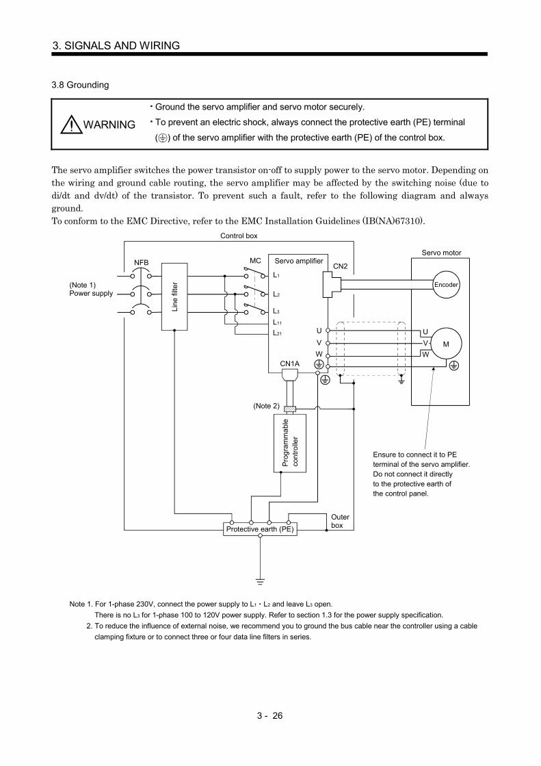
3 - 26
3. SIGNALS AND WIRING
3.8 Grounding
WARNING
Ground the servo amplifier and servo motor securely.
To prevent an electric shock, always connect the protective earth (PE) terminal
( ) of the servo amplifier with the protective earth (PE) of the control box.
The servo amplifier switches the power transistor on-off to supply power to the servo motor. Depending onthe wiring and ground cable routing, the servo amplifier may be affected by the switching noise (due todi/dt and dv/dt) of the transistor. To prevent such a fault, refer to the following diagram and alwaysground.To conform to the EMC Directive, refer to the EMC Installation Guidelines (IB(NA)67310).
L1
L2
L3
L11
L21
CN1A
NFB MC
CN2
UVW
M
UVW
(Note 2)
Control box
Servo amplifier
Line
filte
r
Protective earth (PE)
Outerbox
Servo motor
EncoderPr
ogra
mm
able
cont
rolle
r
Ensure to connect it to PEterminal of the servo amplifier.Do not connect it directlyto the protective earth ofthe control panel.
(Note 1)Power supply
Note 1. For 1-phase 230V, connect the power supply to L1 L2 and leave L3 open.There is no L3 for 1-phase 100 to 120V power supply. Refer to section 1.3 for the power supply specification.
2. To reduce the influence of external noise, we recommend you to ground the bus cable near the controller using a cableclamping fixture or to connect three or four data line filters in series.
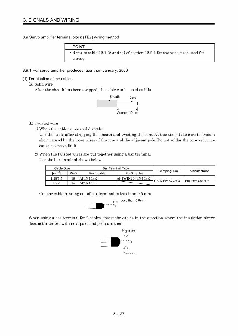
3 - 27
3. SIGNALS AND WIRING
3.9 Servo amplifier terminal block (TE2) wiring method
POINTRefer to table 12.1 2) and (4) of section 12.2.1 for the wire sizes used forwiring.
3.9.1 For servo amplifier produced later than January, 2006
(1) Termination of the cables(a) Solid wire
After the sheath has been stripped, the cable can be used as it is.Sheath Core
Approx. 10mm
(b) Twisted wire1) When the cable is inserted directly
Use the cable after stripping the sheath and twisting the core. At this time, take care to avoid ashort caused by the loose wires of the core and the adjacent pole. Do not solder the core as it maycause a contact fault.
2) When the twisted wires are put together using a bar terminalUse the bar terminal shown below.
Cable Size Bar Terminal Type[mm2] AWG For 1 cable For 2 cables
Crimping Tool Manufacturer
1.25/1.5 16 AI1.5-10BK AI-TWIN2 1.5-10BK2/2.5 14 AI2.5-10BU
CRIMPFOX ZA 3 Phoenix Contact
Cut the cable running out of bar terminal to less than 0.5 mmLess than 0.5mm
When using a bar terminal for 2 cables, insert the cables in the direction where the insulation sleevedoes not interfere with next pole, and pressure then.
Pressure
Pressure

3 - 28
3. SIGNALS AND WIRING
(2) Connection(a) When the cable is inserted directly
Insert the cable to the end pressing the button with a small flat-blade screwdriver or the like.
Button
Small flat blade screwdriver or the like
Twisted wire
When removing the short-circuit bar from across P-D, press the buttons of P and D alternately pulling the short-circuit bar. For the installation, insert the bar straight to the end.
(b) When the twisted wires are put together using a bar terminalInsert a bar terminal with the odd-shaped side of the pressured terminal on the button side.
Bar terminal for one wire or solid wire
Bar terminal for two wires
When two cables are inserted into one opening, a bar terminal for 2 cables is required.

3 - 29
3. SIGNALS AND WIRING
3.9.2 For servo amplifier produced earlier than December, 2005
(1) Termination of the cablesSolid wire: After the sheath has been stripped, the cable can be used as it is.
Approx. 10mm(0.39inch)
Twisted wire: Use the cable after stripping the sheath and twisting the core. At this time, take care toavoid a short caused by the loose wires of the core and the adjacent pole. Do not solderthe core as it may cause a contact fault.Alternatively, a bar terminal may be used to put the wires together.
Cable Size Bar Terminal Type[mm2] AWG For 1 cable For 2 cables
Crimping Tool Manufacturer
1.25/1.5 16 AI1.5-10BK AI-TWIN2 1.5-10BK2/2.5 14 AI2.5-10BU
CRIMPFOX ZA 3 orCRIMPFOX UD 6 Phoenix Contact
(2) ConnectionInsert the core of the cable into the opening and tighten the screw with a flat-blade screwdriver so thatthe cable does not come off. (Tightening torque: 0.3 to 0.4N m(2.7 to 3.5 lb in)) Before inserting thecable into the opening, make sure that the screw of the terminal is fully loose.When using a cable of 1.5mm2 or less, two cables may be inserted into one opening.
To loosen. To tighten.
Opening
Control circuit terminal block
Cable
Flat-blade screwdriver Tip thickness 0.4 to 0.6mm Overall width 2.5 to 3.5mm
Use of a flat-blade torque screwdriver is recommended to manage the screw tightening torque. Thefollowing table indicates the recommended products of the torque screwdriver for tightening torquemanagement and the flat-blade bit for torque screwdriver. When managing torque with a Phillips bit,please consult us.
Product Model Manufacturer/RepresentativeTorque screwdriver N6L TDK Nakamura SeisakushoBit for torque screwdriver B-30, flat-blade, H3.5 X 73L Shiro Sangyo

3 - 30
3. SIGNALS AND WIRING
3.10 Instructions for the 3M connector
When fabricating an encoder cable or the like, securely connect the shielded external conductor of thecable to the ground plate as shown in this section and fix it to the connector shell.
External conductor SheathExternal conductor
Pull back the external conductor to cover the sheath
SheathCore
Strip the sheath.
Screw
Screw
Ground plate
Cable

3 - 31
3. SIGNALS AND WIRING
3.11 Control axis selection
POINTThe control axis number set to SW1 should be the same as the one set tothe servo system controller.
Use the axis select switch (SW1) to set the control axis number for the servo. If the same numbers are setto different control axes in a single communication system, the system will not operate properly. Thecontrol axes may be set independently of the bus cable connection sequence.Set the switch to "F" when executing the test operation mode using MR Configurator (servo configurationsoftware).
Axis select switch (SW1)
1
CB
A98765
43
2
0 F E
D
No. Description
0 Axis 11 Axis 22 Axis 33 Axis 44 Axis 55 Axis 66 Axis 77 Axis 88 Not used9 Not usedA Not usedB Not usedC Not usedD Not usedE Not usedF Test operation mode or
when machine analyzer is used(Refer to section 6.1.2)

3 - 32
3. SIGNALS AND WIRING
3.12 Power line circuit of the MR-J2S-11KB to MR-J2S-22KB
CAUTION
Always connect a magnetic contactor (MC) between the main circuit power supplyand L1, L2, and L3 of the servo amplifier, and configure the wiring to be able toshut down the power supply on the side of the servo amplifier’s power supply. If amagnetic contactor (MC) is not connected, continuous flow of a large current maycause a fire when the servo amplifier malfunctions.
Switch power off at detection of an alarm. Otherwise, a regenerative transistor faultor the like may overheat the regenerative resistor, causing a fire.
During power-on, do not open or close the motor power line. Otherwise, amalfunction or faulty may occur.
POINTThe power-on sequence is the same as in section 3.5.3.
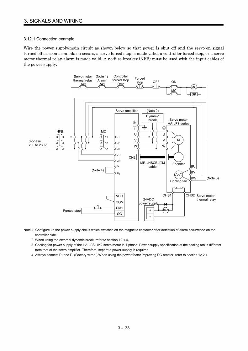
3 - 33
3. SIGNALS AND WIRING
3.12.1 Connection example
Wire the power supply/main circuit as shown below so that power is shut off and the servo-on signalturned off as soon as an alarm occurs, a servo forced stop is made valid, a controller forced stop, or a servomotor thermal relay alarm is made valid. A no-fuse breaker (NFB) must be used with the input cables ofthe power supply.
(Note 1)AlarmRA1
Controllerforced stop
RA2
L1
L2
L3
L11
L21
VDD
COM
EM1
SG
Servo amplifier
CN2
U
V
W
U
V
W
Dynamic break Servo motor
HA-LFS series
M
EncoderBU
Cooling fan
RA3
24VDCpower supply
MR-JHSCBL Mcable
BV
BW
MC
SK
ON
MC
OFFForced
stop
Servo motor thermal relay
RA3
NFB MC
Forced stop
OHS2OHS1 Servo motor thermal relay
(Note 3)
3-phase200 to 230V
(Note 2)
P1
P(Note 4)
Note 1. Configure up the power supply circuit which switches off the magnetic contactor after detection of alarm occurrence on thecontroller side.
2. When using the external dynamic break, refer to section 12.1.4.3. Cooling fan power supply of the HA-LFS11K2 servo motor is 1-phase. Power supply specification of the cooling fan is different
from that of the servo amplifier. Therefore, separate power supply is required.4. Always connect P1 and P. (Factory-wired.) When using the power factor improving DC reactor, refer to section 12.2.4.

3 - 34
3. SIGNALS AND WIRING
3.12.2 Servo amplifier terminals
The positions and signal arrangements of the terminal blocks change with the capacity of the servoamplifier. Refer to section 10.1.
SymbolConnection Target
(Application)Description
L1, L2, L3 Main circuit power supply Supply L1, L2 and L3 with three-phase 200 to 230VAC, 50/60Hz power.U, V, W Servo motor output Connect to the servo motor power supply terminals (U, V, W).L11, L21 Control circuit power supply Supply L11 and L21 with single-phase 200 to 230VAC power.
P, C Regenerative option
The servo amplifier built-in regenerative resistor is not connected at the time ofshipment.When using the regenerative option, wire it across P-C.Refer to section 12.1.1 for details.
NReturn converter
Brake unitWhen using the return converter or brake unit, connect it across P-N.Refer to sections 12.1.2 and 12.1.3 for details.
Protective earth (PE)Connect this terminal to the protective earth (PE) terminals of the servo motorand control box for grounding.
P1, PPower factor improving DC
reactorsP1-P are connected before shipment. When connecting a power factor improvingDC reactor, remove the short bar across P1-P. Refer to section 12.2.4 for details.
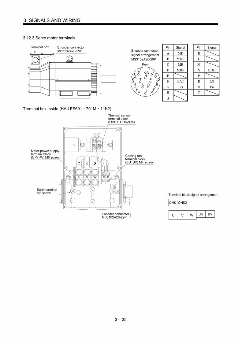
3 - 35
3. SIGNALS AND WIRING
3.12.3 Servo motor terminals
Pin Signal Pin Signal
A MD KB MDR LC MR MD MRR N SHDE PF BAT R LGG LG S P5H T
Encoder connectorMS3102A20-29P
Terminal box
Key
AN
G
S R
T P
H F
J EK D
LM B
C
Encoder connector signal arrangementMS3102A20-29P
J
Terminal box inside (HA-LFS601 701M 11K2)
Earth terminalM6 screw
Motor power supplyterminal block(U V W) M6 screw
Encoder connectorMS3102A20-29P
Cooling fanterminal block(BU BV) M4 screw
Thermal sensorterminal block(OHS1 OHS2) M4
U V W BU BV
OHS1OHS2
Terminal block signal arrangement
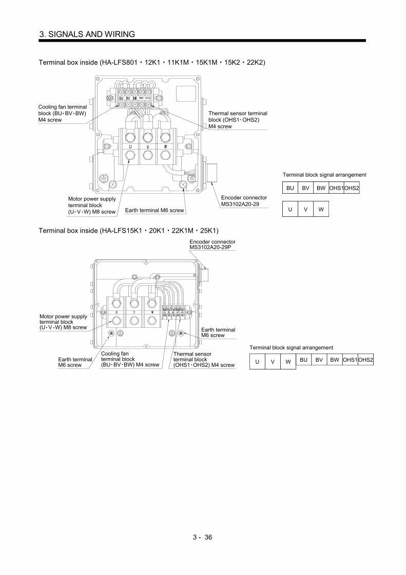
3 - 36
3. SIGNALS AND WIRING
Terminal box inside (HA-LFS801 12K1 11K1M 15K1M 15K2 22K2)
Motor power supplyterminal block(U V W) M8 screw Earth terminal M6 screw
Encoder connectorMS3102A20-29
Thermal sensor terminalblock (OHS1 OHS2)M4 screw
Cooling fan terminalblock (BU BV BW)M4 screw
U V W
BU BV OHS1OHS2BW
Terminal block signal arrangement
Terminal box inside (HA-LFS15K1 20K1 22K1M 25K1)Encoder connectorMS3102A20-29P
Earth terminalM6 screw
Thermal sensorterminal block(OHS1 OHS2) M4 screw
Cooling fanterminal block(BU BV BW) M4 screw
Earth terminalM6 screw
Motor power supplyterminal block(U V W) M8 screw
BVU V W BU BW OHS1OHS2
Terminal block signal arrangement
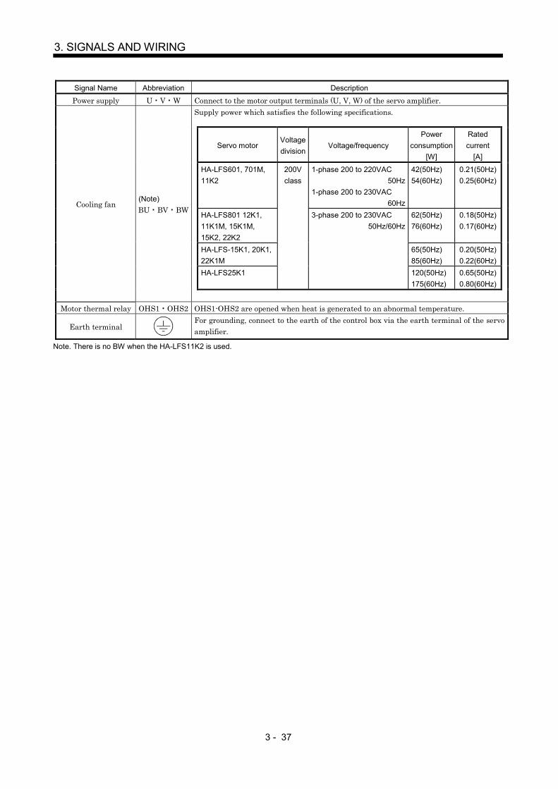
3 - 37
3. SIGNALS AND WIRING
Signal Name Abbreviation Description
Power supply U V W Connect to the motor output terminals (U, V, W) of the servo amplifier.Supply power which satisfies the following specifications.
Servo motorVoltagedivision
Voltage/frequencyPower
consumption[W]
Ratedcurrent
[A]
HA-LFS601, 701M,11K2
200Vclass
1-phase 200 to 220VAC50Hz
1-phase 200 to 230VAC60Hz
42(50Hz)54(60Hz)
0.21(50Hz)0.25(60Hz)
HA-LFS801 12K1,11K1M, 15K1M,15K2, 22K2
3-phase 200 to 230VAC50Hz/60Hz
62(50Hz)76(60Hz)
0.18(50Hz)0.17(60Hz)
HA-LFS-15K1, 20K1,22K1M
65(50Hz)85(60Hz)
0.20(50Hz)0.22(60Hz)
HA-LFS25K1 120(50Hz)175(60Hz)
0.65(50Hz)0.80(60Hz)
Cooling fan(Note)BU BV BW
Motor thermal relay OHS1 OHS2 OHS1-OHS2 are opened when heat is generated to an abnormal temperature.
Earth terminalFor grounding, connect to the earth of the control box via the earth terminal of the servoamplifier.
Note. There is no BW when the HA-LFS11K2 is used.

3 - 38
3. SIGNALS AND WIRING
MEMO
4 - 1
4. OPERATION AND DISPLAY
4. OPERATION AND DISPLAY
4.1 When switching power on for the first time
Before starting operation, check the following.
(1) Wiring(a) A correct power supply is connected to the power input terminals (L1, L2, L3, L11, L21) of the servo
amplifier.
(b) The servo motor power supply terminals (U, V, W) of the servo amplifier match in phase with thepower input terminals (U, V, W) of the servo motor.
(c) The servo motor power supply terminals (U, V, W) of the servo amplifier are not shorted to thepower input terminals (L1, L2, L3) of the servo motor.
(d) The earth terminal of the servo motor is connected to the PE terminal of the servo amplifier.
(e) Note the following when using the regenerative option, brake unit or power regeneration converter.
1) For the MR-J2S-350B or less, the lead has been removed from across D-P of the control circuitterminal block, and twisted cables are used for its wiring.
2) For the MR-J2S-500B MR-J2S-700B, the lead has been removed from across P-C of the servoamplifier built-in regenerative resistor, and twisted cables are used for its wiring.
(f) 24VDC or higher voltages are not applied to the pins of connector CN3.
(g) SD and SG of connector CN3 are not shorted.
(h) The wiring cables are free from excessive force.
(i) CN1A should be connected with the bus cable connected to the servo system controller or precedingaxis servo amplifier, and CN1B should connected with the bus cable connected to the subsequentaxis servo amplifier or with the termination connector (MR-A-TM.)
(2) Axis numberThe axis number setting of SW1 should be the same as that of the servo system controller. (Refer tosection 3.11.)
(3) ParametersOn the servo system controller screen or using the MR Configurator (servo configuration software),make sure that correct values have been set in the parameters.
(4) EnvironmentSignal cables and power cables are not shorted by wire offcuts, metallic dust or the like.
(5) Machine(a) The screws in the servo motor installation part and shaft-to-machine connection are tight.
(b) The servo motor and the machine connected with the servo motor can be operated.
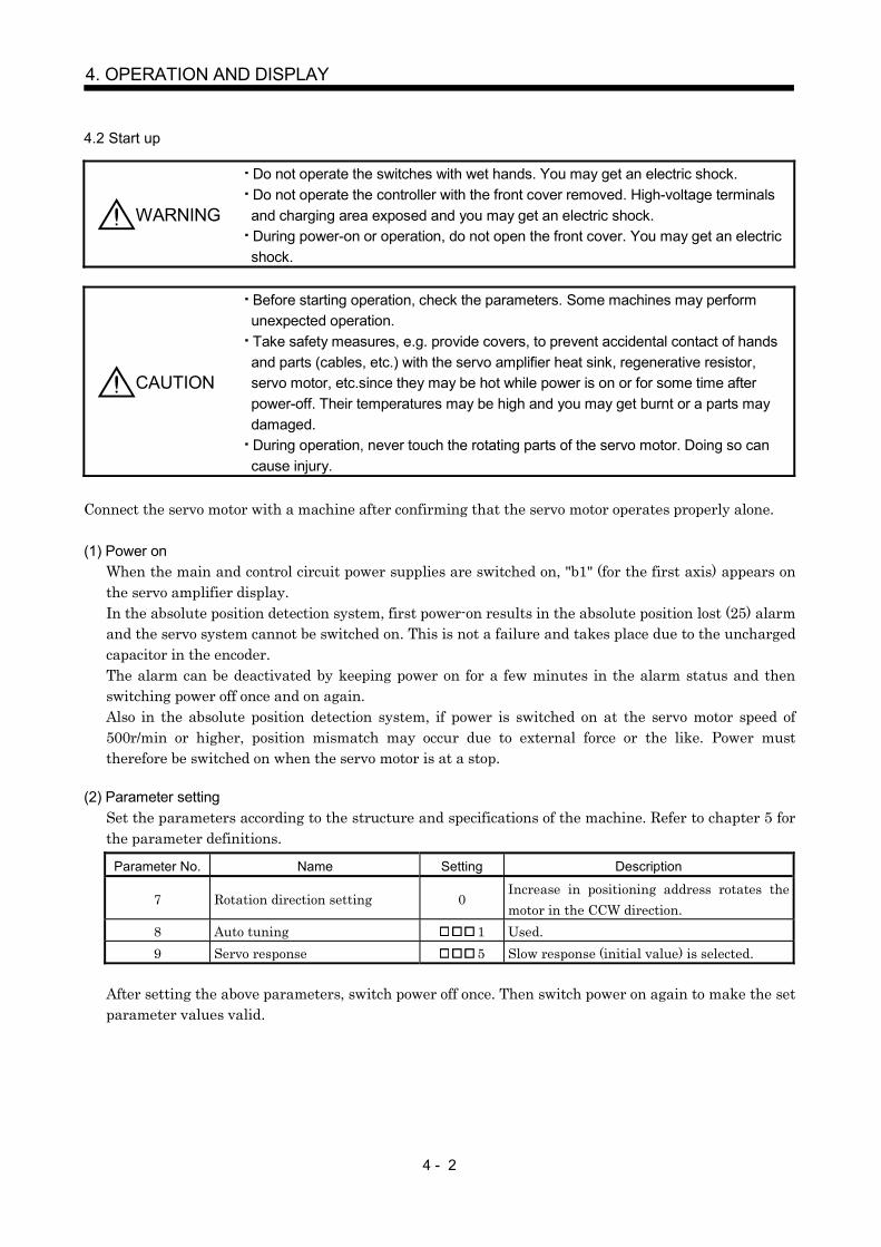
4 - 2
4. OPERATION AND DISPLAY
4.2 Start up
WARNING
Do not operate the switches with wet hands. You may get an electric shock.Do not operate the controller with the front cover removed. High-voltage terminalsand charging area exposed and you may get an electric shock.During power-on or operation, do not open the front cover. You may get an electricshock.
CAUTION
Before starting operation, check the parameters. Some machines may performunexpected operation.Take safety measures, e.g. provide covers, to prevent accidental contact of handsand parts (cables, etc.) with the servo amplifier heat sink, regenerative resistor,servo motor, etc.since they may be hot while power is on or for some time afterpower-off. Their temperatures may be high and you may get burnt or a parts maydamaged.During operation, never touch the rotating parts of the servo motor. Doing so cancause injury.
Connect the servo motor with a machine after confirming that the servo motor operates properly alone.
(1) Power onWhen the main and control circuit power supplies are switched on, "b1" (for the first axis) appears onthe servo amplifier display.In the absolute position detection system, first power-on results in the absolute position lost (25) alarmand the servo system cannot be switched on. This is not a failure and takes place due to the unchargedcapacitor in the encoder.The alarm can be deactivated by keeping power on for a few minutes in the alarm status and thenswitching power off once and on again.Also in the absolute position detection system, if power is switched on at the servo motor speed of500r/min or higher, position mismatch may occur due to external force or the like. Power musttherefore be switched on when the servo motor is at a stop.
(2) Parameter settingSet the parameters according to the structure and specifications of the machine. Refer to chapter 5 forthe parameter definitions.
Parameter No. Name Setting Description
7 Rotation direction setting 0Increase in positioning address rotates themotor in the CCW direction.
8 Auto tuning 1 Used.9 Servo response 5 Slow response (initial value) is selected.
After setting the above parameters, switch power off once. Then switch power on again to make the setparameter values valid.

4 - 3
4. OPERATION AND DISPLAY
(3) Servo-onSwitch the servo-on in the following procedure.
1) Switch on main circuit/control circuit power supply.
2) The controller transmits the servo-on command.
When placed in the servo-on status, the servo amplifier is ready to operate and the servo motor islocked.
(4) Home position returnAlways perform home position return before starting positioning operation.
(5) StopIf any of the following situations occurs, the servo amplifier suspends the running of the servo motorand brings it to a stop.When the servo motor is equipped with an electromagnetic brake, refer to section 3.7.
Operation/command Stopping condition
Servo off command The base circuit is shut off and the servo motor coasts.
Servo system controllerForced stop command
The base circuit is shut off and the dynamic brake operates tobring the servo motor to stop. The controller forced stop warning(E7) occurs.
Alarm occurrenceThe base circuit is shut off and the dynamic brake operates tobring the servo motor to stop.
Servo amplifierForced stop(EM1) OFF
The base circuit is shut off and the dynamic brake operates tobring the servo motor to stop. The servo forced stop warning(E6) occurs.

4 - 4
4. OPERATION AND DISPLAY
4.3 Servo amplifier display
On the servo amplifier display (two-digit, seven-segment display), check the status of communication withthe servo system controller at power-on, check the axis number, and diagnose a fault at occurrence of analarm.(1) Display sequence
Servo amplifier power ON
Waiting for servo system controllerpower to switch ON
Servo system controller power ON
When alarm occurs,alarm code appears.
Ready ON
Ready OFF/servo OFF
Ready ON/servo OFF
Servo ON
Ordinary operation
Servo system controller power OFF
Ready ON/servo ON
(Note)
(Note)
(Note)
Servo system controller power ON
During forced stop and forced stop
Forced stop and forced stopreset
or
Note. The right-hand segments of b1, c1 and d1 indicate the axis number. (Axis 1 in this example)
Initial data communicationwith servo system controller
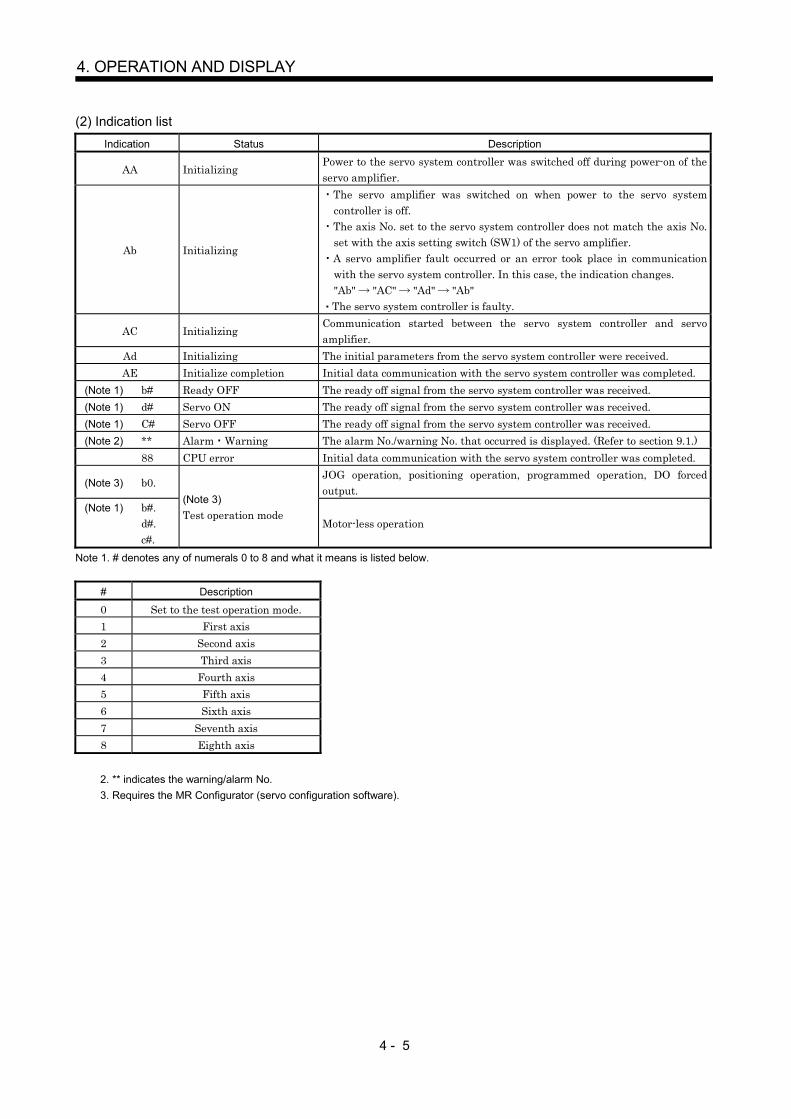
4 - 5
4. OPERATION AND DISPLAY
(2) Indication listIndication Status Description
AA InitializingPower to the servo system controller was switched off during power-on of theservo amplifier.
Ab Initializing
The servo amplifier was switched on when power to the servo systemcontroller is off.The axis No. set to the servo system controller does not match the axis No.set with the axis setting switch (SW1) of the servo amplifier.A servo amplifier fault occurred or an error took place in communicationwith the servo system controller. In this case, the indication changes."Ab" "AC" "Ad" "Ab"The servo system controller is faulty.
AC InitializingCommunication started between the servo system controller and servoamplifier.
Ad Initializing The initial parameters from the servo system controller were received.AE Initialize completion Initial data communication with the servo system controller was completed.
(Note 1) b# Ready OFF The ready off signal from the servo system controller was received.(Note 1) d# Servo ON The ready off signal from the servo system controller was received.(Note 1) C# Servo OFF The ready off signal from the servo system controller was received.(Note 2) ** Alarm Warning The alarm No./warning No. that occurred is displayed. (Refer to section 9.1.)
88 CPU error Initial data communication with the servo system controller was completed.
(Note 3) b0.JOG operation, positioning operation, programmed operation, DO forcedoutput.
(Note 1) b#.d#.c#.
(Note 3)Test operation mode
Motor-less operation
Note 1. # denotes any of numerals 0 to 8 and what it means is listed below.
# Description
0 Set to the test operation mode.1 First axis2 Second axis3 Third axis4 Fourth axis5 Fifth axis6 Sixth axis7 Seventh axis8 Eighth axis
2. ** indicates the warning/alarm No.3. Requires the MR Configurator (servo configuration software).
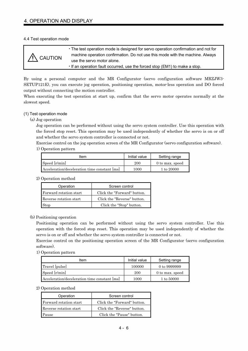
4 - 6
4. OPERATION AND DISPLAY
4.4 Test operation mode
CAUTION
The test operation mode is designed for servo operation confirmation and not formachine operation confirmation. Do not use this mode with the machine. Alwaysuse the servo motor alone.If an operation fault occurred, use the forced stop (EM1) to make a stop.
By using a personal computer and the MR Configurator (servo configuration software MRZJW3-SETUP121E), you can execute jog operation, positioning operation, motor-less operation and DO forcedoutput without connecting the motion controller.When executing the test operation at start up, confirm that the servo motor operates normally at theslowest speed.
(1) Test operation mode(a) Jog operation
Jog operation can be performed without using the servo system controller. Use this operation withthe forced stop reset. This operation may be used independently of whether the servo is on or offand whether the servo system controller is connected or not.Exercise control on the jog operation screen of the MR Configurator (servo configuration software).1) Operation pattern
Item Initial value Setting range
Speed [r/min] 200 0 to max. speedAcceleration/deceleration time constant [ms] 1000 1 to 20000
2) Operation method
Operation Screen control
Forward rotation start Click the "Forward" button.Reverse rotation start Click the "Reverse" button.Stop Click the "Stop" button.
(b) Positioning operationPositioning operation can be performed without using the servo system controller. Use thisoperation with the forced stop reset. This operation may be used independently of whether theservo is on or off and whether the servo system controller is connected or not.Exercise control on the positioning operation screen of the MR Configurator (servo configurationsoftware).1) Operation pattern
Item Initial value Setting range
Travel [pulse] 100000 0 to 9999999Speed [r/min] 200 0 to max. speedAcceleration/deceleration time constant [ms] 1000 1 to 50000
2) Operation method
Operation Screen control
Forward rotation start Click the "Forward" button.Reverse rotation start Click the "Reverse" button.Pause Click the "Pause" button.

4 - 7
4. OPERATION AND DISPLAY
(c) Program operationPositioning operation can be performed in two or more operation patterns combined, without usingthe servo system controller. Use this operation with the forced stop reset. This operation may beused independently of whether the servo is on or off and whether the servo system controller isconnected or not.Exercise control on the programmed operation screen of the MR Configurator (servo configurationsoftware). For full information, refer to the MR Configurator (Servo Configuration Software)Installation Guide.
Operation Screen Control
Start Click the "Start" button.Stop Click the "Reset" button.
(d) Motorless operation
POINTMotor-less operation may be used with the MR Configurator (servoconfiguration software). Usually, however, use motor-less operation whichis available by making the servo system controller parameter setting.
Without connecting the servo motor, output signals or status displays can be provided in responseto the servo system controller commands as if the servo motor is actually running. This operationmay be used to check the servo system controller sequence. Use this operation with the forced stopreset. Use this operation with the servo amplifier connected to the servo system controller.Exercise control on the motor-less operation screen of the MR Configurator (servo configurationsoftware).
1) Load conditions
Load Item Condition
Load torque 0Load inertia moment ratio Same as servo motor inertia moment
2) AlarmsThe following alarms and warning do not occur. However, the other alarms and warnings occuras when the servo motor is connected.
Encoder error 1 (16)Encoder error 2 (20)Absolute position erasure (25)Battery cable breakage warning (92)Battery warning (9F)
(e) Output signal (DO) forced outputOutput signals can be switched on/off forcibly independently of the servo status. Use this functionfor output signal wiring check, etc.Exercise control on the DO forced output screen of the MR Configurator (servo configurationsoftware).

4 - 8
4. OPERATION AND DISPLAY
(2) ConfigurationConfiguration should be as in section 3.1. Always install a forced stop switch to enable a stop atoccurrence of an alarm.
(3) Operation procedure(a) Jog operation, positioning operation, program operation, DO forced output.
1) Switch power off.
2) Set SW1 to “F”.When SW1 is set to the axis number and operation is performed by the servo system controller,the test operation mode screen is displayed on the personal computer, but no function isperformed.
3) Switch servo amplifier power on.When initialization is over, the display shows the following screen.
Decimal point flickers.
4) Perform operation with the personal computer.
(b) Motor-less operation1) Switch off the servo amplifier.
2) Perform motor-less operation with the personal computer.The display shows the following screen.
Decimal point flickers.

5 - 1
5. PARAMETERS
5. PARAMETERS
CAUTION Never adjust or change the parameter values extremely as it will make operationinstable.
POINTWhen the servo amplifier is connected with the servo system controller, theparameters are set to the values of the servo system controller. Switchingpower off, then on makes the values set on the MR Configurator (servoconfiguration software) invalid and the servo system controller values valid.In the manufacturer setting parameters, do not set any values other thanthe initial values.Setting may not be made to some parameters and ranges depending on themodel or version of the servo system controller. For details, refer to theservo system controller user's manual.
5.1 Parameter write inhibit
POINTWhen setting the parameter values from the servo system controller, theparameter No. 40 setting need not be changed.
In this servo amplifier, the parameters are classified into the basic parameters (No. 1 to 11), adjustmentparameters (No. 12 to 26) and expansion parameters (No. 27 to 40) according to their safety aspects andfrequencies of use. The values of the basic parameters may be set/changed by the customer, but those ofthe adjustment and expansion parameters cannot. When in-depth adjustment such as gain adjustment isrequired, change the parameter No. 40 value to make all parameters accessible. Parameter No. 40 ismade valid by switching power off, then on after setting its value.The following table indicates the parameters which are enabled for reference and write by parameter No.40 setting.
Setting Operation Operation from controller Operation from MR Configurator(servo configuration software)
Reference0000(initial value) Write Parameter No. 1 to 75 Parameter No. 1 to 11 40
Reference000A Write Parameter No. 1 to 75 Parameter No. 40
Reference Parameter No. 1 to 40000C Write Parameter No. 1 to 75 Parameter No. 1 to 11 40Reference000E Write Parameter No. 1 to 75 Parameter No. 1 to 40
Reference000F Write Parameter No. 1 to 75 Parameter No. 1 to 75
Reference Parameter No. 1 to 40100E Write Parameter No. 1 to 75 Parameter No. 40
5.2 Lists
POINTFor any parameter whose symbol is preceded by*, set the parameter valueand switch power off once, then switch it on again to make that parametersetting valid. The parameter is set when communication between theservo system controller and servo amplifier is established (b* isdisplayed). After that, power the servo amplifier off once and then onagain.

5 - 2
5. PARAMETERS
(1) Item list
Classifi-cation No. Symbol Name
(Note 1)InitialValue
Unit Customersetting
1 *AMS Amplifier setting 00002 *REG Regenerative resistor 00003 00804 0005
For manufacturer setting by servo system controllerAutomatically set from the servo system controller 1
6 *FBP Feedback pulse number 07 *POL Rotation direction selection 08 ATU Auto tuning 0001
9 RSP Servo response7kW or
less: 000511kW or
more: 000210 TLP Forward rotation torque limit (Note 2) 300 %
Basi
c par
amet
ers
11 TLN Reverse rotation torque limit (Note 2) 300 %12 GD2 Ratio of load inertia to servo motor inertia (load inertia ratio) 7.0 times
13 PG1 Position control gain 17kW orless: 3511kW ormore: 19
rad/s
14 VG1 Speed control gain 17kW orless: 17711kW ormore: 96
rad/s
15 PG2 Position control gain 27kW orless: 3511kW ormore: 19
rad/s
16 VG2 Speed control gain 2
7kW orless: 81711kW or
more:455
rad/s
17 VIC Speed integral compensation7kW orless:48
11kW ormore:91
ms
18 NCH Machine resonance suppression filter 1 (Notch filter) 000019 FFC Feed forward gain 0 %20 INP In-position range 100 pulse21 MBR Electromagnetic brake sequence output 0 ms22 MOD Analog monitor output 000123 *OP1 Optional function 1 000024 *OP2 Optional function 2 000025 LPF Low-pass filter/adaptive vibration suppression control 0000
Adju
stm
ent p
aram
eter
s
26 For manufacturer setting 027 MO1 Analog monitor 1 offset 0 mV28 MO2 Analog monitor 2 offset 0 mV29 For manufacturer setting 000130 ZSP Zero speed 50 r/min
31 ERZ Error excessive alarm level 80 (Note 3)0.025rev
32 OP5 Optional function 5 000033 *OP6 Optional function 6 000034 VPI PI-PID control switch-over position droop 0 pulse35 For manufacturer setting 036 VDC Speed differential compensation 98037 For manufacturer setting 001038 *ENR Encoder pulses output 4000 pulse/rev39 For manufacturer setting 0
Expa
nsio
n pa
ram
eter
s
40 *BLK Parameter write inhibit (Note 2) 0000Note 1. Factory settings of the servo amplifier. Connecting it with the servo system controller and switching power on changes them to
the settings of the servo system controller.2. Setting and changing cannot be made from the peripheral software of the motion controller.3. The setting unit of 0.025rev applies for the servo amplifier of software version B1 or later. For the amplifier of software version
older than B1, the setting unit of 0.1rev is applied.
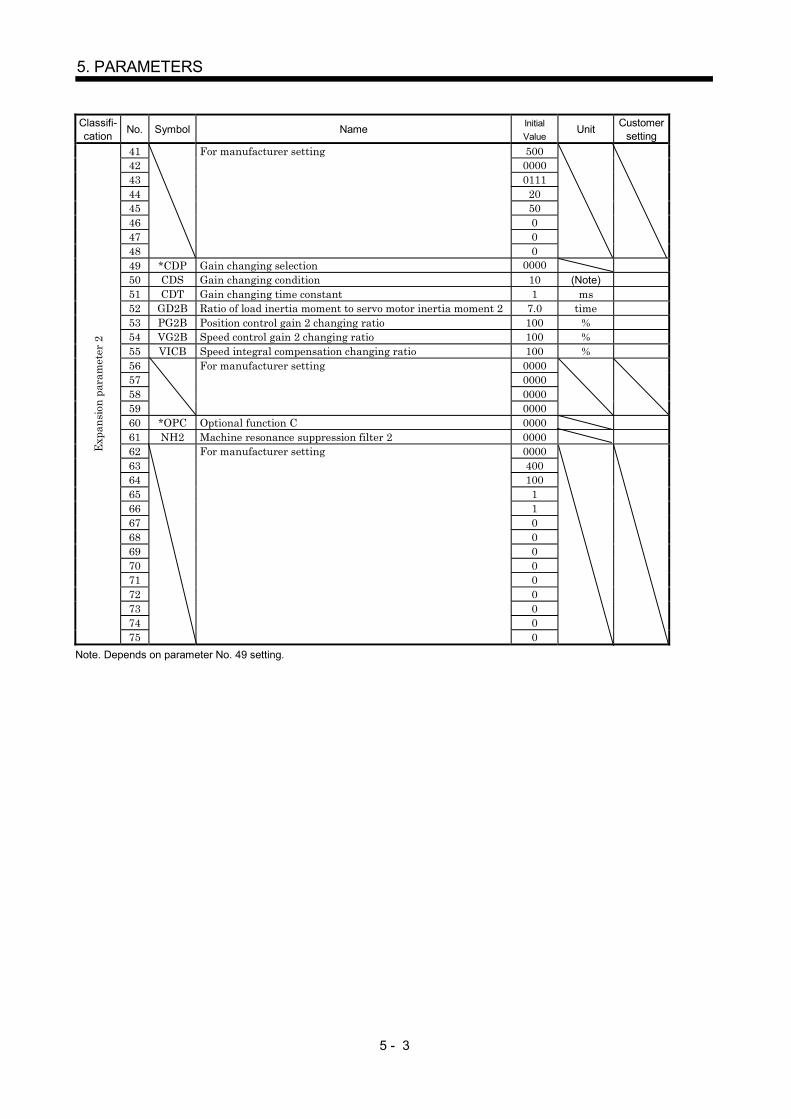
5 - 3
5. PARAMETERS
Classifi-cation No. Symbol Name Initial
ValueUnit Customer
setting41 50042 000043 011144 2045 5046 047 048
For manufacturer setting
049 *CDP Gain changing selection 000050 CDS Gain changing condition 10 (Note)51 CDT Gain changing time constant 1 ms52 GD2B Ratio of load inertia moment to servo motor inertia moment 2 7.0 time53 PG2B Position control gain 2 changing ratio 100 %54 VG2B Speed control gain 2 changing ratio 100 %55 VICB Speed integral compensation changing ratio 100 %56 000057 000058 000059
For manufacturer setting
000060 *OPC Optional function C 000061 NH2 Machine resonance suppression filter 2 000062 000063 40064 10065 166 167 068 069 070 071 072 073 074 0
Expa
nsio
n pa
ram
eter
2
75
For manufacturer setting
0Note. Depends on parameter No. 49 setting.

5 - 4
5. PARAMETERS
(2) Details list
Classifi-cation
No. Symbol Name and FunctionInitialValue
UnitSettingRange
1 *AMS Amplifier settingUsed to select the absolute position detection.
Absolute position detection selection 0: Invalid (Used in incremental system.) 1: Valid (Used in absolute position detection system.)
0 00
0000 Refer tonameandfunctioncolumn.
Regenerative resistorUsed to select the regenerative option used.
Regenerative selection option00: Regenerative option is not used with 7kW or
less servo amplifier (The built-in regenerative resistor is used. However, the MR-J2S-10B does not have a built-in regenerative resistor and therefore cannot use it.)
Supplied regenerative resistors or regenerative option is used with 11k to 22kW amplifier01: FR-RC, FR-BU2, FR-CV05: MR-RB3208: MR-RB3009: MR-RB50 (Cooling fan is required)0B: MR-RB310C: MR-RB51 (Cooling fan is required)0E: When regenerative resistors or regenerative
option supplied to 11k to 22kW are cooled by cooling fans to increase capability
10: MR-RB03211: MR-RB12The MR-RB65, 66 and 67 are regenerative options that have encased the GRZG400-2 , GRZG400-1 and GRZG400-0.8 , respectively. When using any of these regenerative options, make the same parameter setting as when using the GRZG400-2 , GRZG400-1 or GRZG400-0.8 (supplied regenerative resistors or regenerative option is used with 11k to 22kW servo amplifier).
0 0
Select the external dynamic brake.0: Invalid1: ValidSelect "1" when using the external dynamic brake with the MR-J2S-11KB to 22KB.
POINTWrong setting may cause the regenerative optionto burn.
If the regenerative option selected is not for usewith the servo amplifier, parameter error (37)occurs.
2 *REG 0000 Refer tonameandfunctioncolumn.
3 00804 0000
Basi
c par
amet
ers
5
For manufacturer setting by servo system controllerAutomatically set from the servo system controller
1

5 - 5
5. PARAMETERS
Classifi-cation
No. Symbol Name and FunctionInitialValue
UnitSettingRange
Feedback pulse numberSet the number of pulses per revolution in the controller side commandunit. Information on the motor such as the feedback pulse value, presentposition, droop pulses and within-one-revolution position are derivedfrom the values converted into the number of pulses set here.
Setting Number of feedback pulses0 163841 81926 327687 131072
255 Depending on the number of motor resolution pulses.
POINTIf the number of pulses set exceeds the actual motorresolution, the motor resolution is set automatically.
6 *FBP 0 Refer tonameandfunctioncolumn.
7 *POL Rotation direction selectionUsed to select the rotation direction of the servo motor.0: Forward rotation (CCW) with the increase of the positioning
address.1: Reverse rotation (CW) with the increase of the positioning
address.
CCW
CW
0 Refer tonameandfunctioncolumn.
Basi
c par
amet
ers
8 ATU Auto tuningUsed to select the gain adjustment mode of auto tuning.
Fixes the load inertiamoment ratio set inparameter No. 12. Response level settingcan be changed.
0 0 0Gain adjustment mode selection(For details, refer to section 6.1.1.)
Set value
Gain adjustment mode Description
0 Interpolation mode Fixes position controlgain 1 (parameter No. 13).
Auto tuning mode 1 Ordinary auto tuning.13
4
Auto tuning mode 2
Manual mode1 Simple manual adjustment.
2 Manual mode 2 Manual adjustment of all gains.
0001 Refer tonameandfunctioncolumn.

5 - 6
5. PARAMETERS
Classifi-cation
No. Symbol Name and FunctionInitialValue
UnitSettingRange
9 RSP Servo responseUsed to select the response of auto tuning.
Response level selection
If the machine hunts or generates large gearsound, decrease the set value.To improve performance, e.g. shorten thesettling time, increase the set value.
Setvalue
Responselevel
1 Lowresponse
Middle response
Highresponse
Machine resonancefrequency guideline
15Hz2 20Hz3 25Hz4 30Hz5 35Hz6 45Hz7 55Hz8 70Hz9 85HzA 105HzB 130HzC 160HzD 200HzE 240HzF 300Hz
0 00
7kW orless
:0005
11kW ormore:0002
Refer tonameandfunctioncolumn.
10 TLP Forward rotation torque limitAssume that the rated torque is 100[%].Used to limit the torque in the forward rotation driving mode andreverse rotation regenerative mode.In other than the test operation mode on the MR Configurator (servoconfiguration software), the torque limit value on the servo systemcontroller side is made valid.
300 % 0to
500
Basi
c par
amet
ers
11 TLN Reverse rotation torque limitAssume that the rated torque is 100[%].Used to limit the torque in the forward rotation driving mode andforward rotation regenerative mode.In other than the test operation mode on the MR Configurator (servoconfiguration software), the torque limit value on the servo systemcontroller side is made valid.
300 % 0to
500
12 GD2 Ratio of load inertia to servo motor inertia (load inertia ratio)Used to set the ratio of the load inertia (inertia moment) to theinertia moment of the servo motor shaft. When auto tuning mode 1and interpolation mode is selected, the result of auto tuning isautomatically used. (Refer to section 6.1.1)
7.0 times 0.0to
300.0
Adju
stm
ent p
aram
eter
s
13 PG1 Position control gain 1Used to set the gain of position loop 1. Increase the gain to improvetrack ability performance in response to the position command.When auto turning mode 1,2 is selected, the result of auto turning isautomatically used.
7kW orless:35
11kW ormore:19
rad/s 4to
2000

5 - 7
5. PARAMETERS
Classifi-cation
No. Symbol Name and FunctionInitialValue
UnitSettingRange
14 VG1 Speed control gain 1Normally this parameter setting need not be changed. Higher settingincreases the response level but is liable to generate vibration and/ornoise.When auto tuning mode 1,2 and interpolation mode is selected, theresult of auto tuning is automatically used.
7kW orless:177
11kW ormore:96
rad/s 20to
5000
15 PG2 Position control gain 2Used to set the gain of the position loop.Set this parameter to increase position response to load disturbance.Higher setting increases the response level but is liable to generatevibration and/or noise.When auto tuning mode 1 2, manual mode and interpolation modeis selected, the result of auto tuning is automatically used.
7kW orless:35
11kW ormore:19
rad/s 1to
1000
16 VG2 Speed control gain 2Set this parameter when vibration occurs on machines of lowrigidity or large backlash.Higher setting increases the response level but is liable to generatevibration and/or noise.When auto tuning mode 1 2 and interpolation mode is selected, theresult of auto tuning is automatically used.
7kW orless:817
11kW ormore:455
rad/s 20to
20000
17 VIC Speed integral compensationUsed to set the constant of integral compensation.When auto tuning mode 1 2 and interpolation mode is selected, theresult of auto tuning is automatically used.
7kW orless:48
11kW ormore:91
ms 1to
1000
18 NCH Machine resonance suppression filter 1 (Notch filter)Used to select the machine resonance suppression filter.(Refer to section 7.2.)
23
0
01
Notch frequency selection
0001020304050607
Setting Frequency
Invalid4500225015001125900750642.9
08090A0B0C0D0E0F
Setting
562.5500450409.1375346.2321.4300
Frequency
1011121314151617
Setting
281.3264.7250236.8225214.3204.5195.7
Frequency
18191A1B1C1D1E1F
Setting
187.5180173.1166.7160.1155.2150145.2
Frequency
Notch depth selectionSetting Depth Gain
Deep
Shallow
to
4dB
40dB14dB8dB
0000 Refer tonameandfunctioncolumn.
Adju
stm
ent p
aram
eter
s
19 FFC Feed forward gainSet the feed forward gain. When the setting is 100%, the drooppulses during operation at constant speed are nearly zero. However,sudden acceleration/deceleration will increase the overshoot. As aguideline, when the feed forward gain setting is 100%, set 1s or moreas the acceleration/deceleration time constant up to the rated speed.
0 % 0to
100

5 - 8
5. PARAMETERS
Classifi-cation
No. Symbol Name and FunctionInitialValue
UnitSettingRange
20 INP In-position rangeUsed to set the droop pulse range in which the in-position (INP) willbe output to the controller. Make setting in the feedback pulse unit(parameter No. 6).For example, when you want to set 10 m in the conditions that theball screw is direct coupled, the lead is 10mm, and the feedbackpulses are 8192 pulses/rev (parameter No. 6 : 1), set "8" as indicatedby the following expression.
10 10 6
10 10 3 8192 8.192 8
100 pulse 0to
50000
21 MBR Electromagnetic brake sequence outputUsed to set a time delay (Tb) from when the electromagnetic brakeinterlock signal (MBR) turns off until the base circuit is shut off.
0 ms 0to
100022 MOD Analog monitor output
Used to select the signal provided to the analog monitor(MO1) analog monitor (MO2).(Refer to section 5.3.)
Analog monitor1 (MO1)Setting
0 Servo motor speed ( 8V/max. speed)1 Torque ( 8V/max. torque) (Note)
2 Servo motor speed ( 8V/max. speed)3 Torque ( 8V/max. torque) (Note)
4 Current command ( 8V/max. current command)5 Speed command ( 8/max. speed)6 Droop pulses ( 10V/128 pulses)7 Droop pulses ( 10V/2048 pulses)8 Droop pulses ( 10V/8192 pulses)9 Droop pulses ( 10V/32768 pulses)A Droop pulses ( 10V/131072 pulses)
00
B Bus voltage ( 8V/400V)
Analog monitor2 (MO2)
Note. 8V is outputted at the maximum torque.
0001 Refer tonameandfunctioncolumn.
Adju
stm
ent p
aram
eter
s
23 *OP1 Optional function 1Used to make the servo forced stop function invalid.
Servo forced stop selection0: Valid (Use the forced stop (EM1).) 1: Invalid (Do not use the forced stop (EM1).) Automatically switched on internally
00 0
0000 Refer tonameandfunctioncolumn.
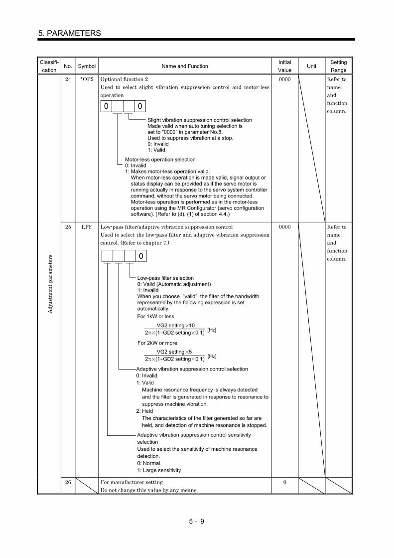
5 - 9
5. PARAMETERS
Classifi-cation
No. Symbol Name and FunctionInitialValue
UnitSettingRange
24 *OP2 Optional function 2Used to select slight vibration suppression control and motor-lessoperation
0 0Slight vibration suppression control selectionMade valid when auto tuning selection isset to "0002" in parameter No.8.Used to suppress vibration at a stop.0: Invalid1: Valid
Motor-less operation selection0: Invalid1: Makes motor-less operation valid. When motor-less operation is made valid, signal output or status display can be provided as if the servo motor is running actually in response to the servo system controller command, without the servo motor being connected. Motor-less operation is performed as in the motor-less operation using the MR Configurator (servo configuration software). (Refer to (d), (1) of section 4.4.)
0000 Refer tonameandfunctioncolumn.
25 LPF Low-pass filter/adaptive vibration suppression controlUsed to select the low-pass filter and adaptive vibration suppressioncontrol. (Refer to chapter 7.)
Low-pass filter selection0: Valid (Automatic adjustment)1: InvalidWhen you choose "valid", the filter of the handwidth represented by the following expression is set automatically.
0
0: Invalid1: Valid Machine resonance frequency is always detected and the filter is generated in response to resonance to suppress machine vibration.2: Held The characteristics of the filter generated so far are held, and detection of machine resonance is stopped.
Adaptive vibration suppression control selection
Adaptive vibration suppression control sensitivityselectionUsed to select the sensitivity of machine resonancedetection.0: Normal1: Large sensitivity
2 (1 GD2 setting 0.1) VG2 setting 10
For 1kW or less
2 (1 GD2 setting 0.1) VG2 setting 5
For 2kW or more
[Hz]
[Hz]
0000 Refer tonameandfunctioncolumn.
Adju
stm
ent p
aram
eter
s
26 For manufacturer settingDo not change this value by any means.
0

5 - 10
5. PARAMETERS
Classifi-cation
No. Symbol Name and FunctionInitialValue
UnitSettingRange
27 MO1 Analog monitor 1 offsetUsed to set the offset voltage of the analog monitor1 (MO1) output.
0 mV 999to
99928 MO2 Analog monitor 2 offset
Used to set the offset voltage of the analog monitor2 (MO2) output.0 mV 999
to999
29 For manufacturer settingDo not change this value by any means.
0001
30 ZSP Zero speedUsed to set the output range of the zero speed signal (ZSP).
50 r/min 0to
1000031 ERZ Error excessive alarm level
Used to set the output range of the error excessive alarm.Note: The setting unit of 0.025rev applies for the servo amplifier of
software version B1 or later. For the amplifier of software versionolder than B1, the setting unit of 0.1rev is applied.
80 (Note)0.025rev
1to
1000
32 OP5 Optional function 5Used to select PI-PID control switch-over.
PI-PID control switch over selection 0: PI control is always valid. 1: Droop-based switching is valid in position control mode (refer to parameter No. 34). 2: PID control is always valid.
0 00
0000 Refer tonameandfunctioncolumn.
33 *OP6 Option function 6Used to select the serial communication baud rate, serialcommunication response delay time setting and encoder pulseoutput setting.
0
Serial communication baud rate selection0: 9600[bps]1: 19200[bps]2: 38400[bps]3: 57600[bps]
Serial communication response delay time0: Invalid1: Valid, replay sent in 800 s or more
Encoder pulse output setting selection(refer to parameter No.38)0: Pulse output designation1: Division ratio setting
0000 Refer tonameandfunctioncolumn.
34 VPI PI-PID control switch-over position droopUsed to set the position droop value (number of pulses) at which PIcontrol is switched over to PID control.Set "0001" in parameter No. 32 to make this function valid.
0 pulse 0to
50000
35 For manufacturer settingDo not change this value by any means.
0
36 VDC Speed differential compensationUsed to set the differential compensation.
980 0to
1000
Expa
nsio
n pa
ram
eter
s
37 For manufacturer settingDo not change this value by any means.
0010

5 - 11
5. PARAMETERS
Classifi-cation
No. Symbol Name and FunctionInitialValue
UnitSettingRange
38 *ENR Encoder pulses outputUsed to set the encoder pulses (A-phase, B-phase) output by theservo amplifier.Set the value 4 times greater than the A-phase and B-phase pulses.You can use parameter No. 33 to choose the pulse output setting oroutput division ratio setting.The number of A-phase and B-phase pulses actually output is 1/4times greater than the preset number of pulses.The maximum output frequency is 1.3Mpps (after multiplication by4). Use this parameter within this range.
For pulse output designationSet "0 " (initial value) in parameter No. 33.Set the number of pulses per servo motor revolution.Pulse output set value [pulses/rev]At the setting of 5600, for example, the actually output A-phaseand B-phase pulses are as indicated below.
45600A-phase and B-phase pulses output 1400[pulse]
For output division ratio settingSet "1 " in parameter No. 33.The number of pulses per servo motor revolution is divided by theset value.
Pulse output [pulses/rev]Resolution per servo motor revolution
Set valueAt the setting of 8, for example, the actually output A-phase andB-phase pulses are as indicated below.
A-phase and B-phase pulses output 4096[pulse]8131072
41
4000 pulse/rev 1to
65535
39 For manufacturer settingDo not change this value by any means.
0
Parameter write inhibit
Setting Operation Operation fromcontroller
Operation fromMR Configurator
(servo configuration)
Reference0000(initialvalue)
WriteParameter No. 1to 75
Parameter No. 1to 11 40
Reference000AWrite
Parameter No. 1to 75
Parameter No. 40
Reference Parameter No. 1to 40
000C
Write
Parameter No. 1to 75
Parameter No. 1to 11 40
Reference000EWrite
Parameter No. 1to 75
Parameter No. 1to 40
Reference000FWrite
Parameter No. 1to 75
Parameter No. 1to 75
Reference Parameter No. 1to 40
100E
Write
Parameter No. 1to 75
Parameter No. 40
Expa
nsio
n pa
ram
eter
s
40 *BLK 0000 Refer tonameandfunctioncolumn.

5 - 12
5. PARAMETERS
Classifi-cation
No. Symbol Name and FunctionInitialValue
UnitSettingRange
41 50042 000043 011144 2045 5046 047 048
For manufacturer settingDo not change this value by any means.
049 *CDP Gain changing selection
Select the gain changing condition. (Refer to section 7.5)
Gain changing selectionUnder any of the following conditions, the gains change on the basis of the parameter No. 52 to 55 settings.0: Invalid1: Control instructions from a controller.2: Command frequency (Parameter No.50 setting)3: Droop pulse value (Parameter No.50 setting)4: Servo motor speed (Parameter No.50 setting)
0 0 0
0000 Refer toNameand
functioncolumn.
50 CDS Gain changing conditionUsed to set the value of gain changing condition (commandfrequency, droop pulses, servo motor speed) selected in parameterNo. 49. The set value unit changes with the changing condition item.(Refer to section 7.5)
10 kppspulser/min
0to
9999
51 CDT Gain changing time constantUsed to set the time constant at which the gains will change inresponse to the conditions set in parameters No. PB26 and PB27.(Refer to section 7.6.)
1 ms 0to
100
52 GD2B Ratio of load inertia moment to servo motor inertia moment 2Used to set the ratio of load inertia moment to servo motor inertiamoment when gain changing is valid.
7.0 times 0to
300.053 PG2B Position control gain 2 changing ratio
Used to set the ratio of changing the position control gain 2 whengain changing is valid.Made valid when auto tuning is invalid.
100 % 10to
200
54 VG2B Speed control gain 2 changing ratioUsed to set the ratio of changing the speed control gain 2 when gainchanging is valid.Made valid when auto tuning is invalid.
100 % 10to
200
55 VICB Speed integral compensation changing ratioUsed to set the ratio of changing the speed integral compensationwhen gain changing is valid. Made valid when auto tuning isinvalid.
100 % 50to
1000
56 000057 000058 0000
Expa
nsio
n pa
ram
eter
2
59
For manufacturer settingDo not change this value by any means.
0000
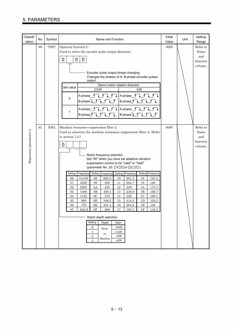
5 - 13
5. PARAMETERS
Classifi-cation
No. Symbol Name and FunctionInitialValue
UnitSettingRange
60 *OPC Optional function CUsed to select the encoder pulse output direction.
CWCCW
Encoder pulse output phase changingChanges the phases of A, B-phase encoder pulses output .
A-phase
B-phase
Servo motor rotation directionSet value
0
1A-phase
B-phase
A-phase
B-phase
A-phase
B-phase
00 0
0000 Refer toNameand
functioncolumn.
Expa
nsio
n pa
ram
eter
2
61 NH2 Machine resonance suppression filter 2Used to selection the machine resonance suppression filter 2. (Referto section 7.2.)
Notch frequency selectionSet "00" when you have set adaptive vibration suppression control to be "valid" or "held"(parameter No. 25: 1 or 2 ).
173.1166.7160.1155.2
145.2
187.50045002250
08090A
23
0
01
0B0C0D0E0F
1011121314151617
18191A1B1C1D1E1F
15001125900750
642.9
500450
409.1375
346.2321.4300
562.5 281.3264.7250236.8225214.3204.5195.7
180
150
01020304050607
40dB14dB8dB4dB
Setting Frequency
Invalid
Notch depth selection
Depth Gain
Deep
Shallow
to
Setting
Setting Setting SettingFrequency Frequency Frequency
0000 Refer toNameand
functioncolumn.

5 - 14
5. PARAMETERS
Classifi-cation
No. Symbol Name and FunctionInitialValue
UnitSettingRange
62 000063 40064 10065 166 167 068 069 070 071 072 073 074 0
Expa
nsio
n pa
ram
eter
2
75
For manufacturer settingDo not change this value by any means.
0
5.3 Analog monitor
The servo status can be output to two channels in terms of voltage. The servo status can be monitoredusing an ammeter.
(1) SettingChange the following digits of parameter No. 22.
Analog monitor 2(MO2) output selection(Signal output to across MO2-LG)
Analog monitor 1(MO1) output selection(Signal output to across MO1-LG)
Parameter No. 22
0 0
Parameters No. 27 and 28 can be used to set the offset voltages to the analog output voltages. Thesetting range is between 999 and 999mV.
Parameter No. Description Setting range [mV]
27 Used to set the offset voltage for the analog monitor 1(MO) output.28 Used to set the offset voltage for the analog monitor 2(MO2) output.
999 to 999
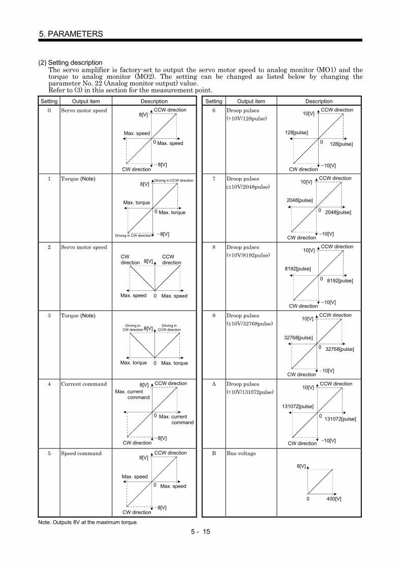
5 - 15
5. PARAMETERS
(2) Setting descriptionThe servo amplifier is factory-set to output the servo motor speed to analog monitor (MO1) and thetorque to analog monitor (MO2). The setting can be changed as listed below by changing theparameter No. 22 (Analog monitor output) value.Refer to (3) in this section for the measurement point.
Setting Output item Description Setting Output item Description
0 Servo motor speed8[V]
Max. speed
0 Max. speed
8[V]
CCW direction
CW direction
6 Droop pulses( 10V/128pulse)
10[V]
0 128[pulse]
10[V]
CCW direction
CW direction
128[pulse]
1 Torque (Note)8[V]
Max. torque
0 Max. torque
8[V]Driving in CW direction
Driving in CCW direction 7 Droop pulses( 10V/2048pulse)
10[V]
0 2048[pulse]
10[V]
CCW direction
CW direction
2048[pulse]
2 Servo motor speed
8[V]
Max. speed 0 Max. speed
CCW direction
CW direction
8 Droop pulses( 10V/8192pulse)
10[V]
0 8192[pulse]
10[V]
CCW direction
CW direction
8192[pulse]
3 Torque (Note)
8[V]
Max. torque 0 Max. torque
Driving in CW direction
Driving in CCW direction
9 Droop pulses( 10V/32768pulse)
10[V]
0 32768[pulse]
10[V]
CCW direction
CW direction
32768[pulse]
4 Current command 8[V]Max. current command
0 Max. current command
8[V]
CCW direction
CW direction
A Droop pulses( 10V/131072pulse)
10[V]
0 131072[pulse]
10[V]
CCW direction
CW direction
131072[pulse]
5 Speed command8[V]
Max. speed0 Max. speed
8[V]
CCW direction
CW direction
B Bus voltage
8[V]
0 400[V]
Note. Outputs 8V at the maximum torque.
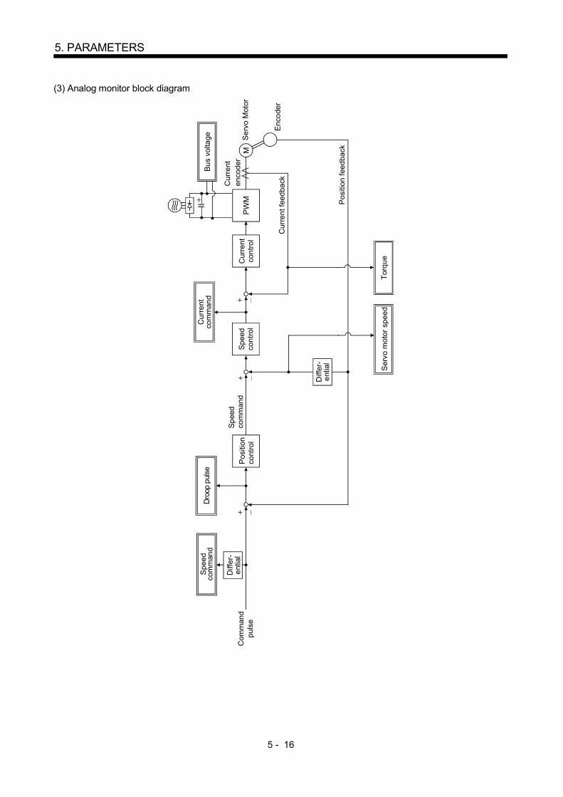
5 - 16
5. PARAMETERS
(3) Analog monitor block diagram
PW
MM
Cur
rent
co
ntro
lSp
eed
cont
rolC
urre
ntco
mm
and
Pos
ition
co
ntro
l
Droo
p pu
lse
Diff
er-
entia
l
Spe
edco
mm
and
Bus
volta
ge
Spee
d co
mm
and
Com
man
dpu
lse
Cur
rent
feed
back
Pos
ition
feed
back
Ser
vo m
otor
spe
ed
Cur
rent
en
code
rSe
rvo
Mot
or
Enco
der
Torq
ue
Diff
er-
entia
l

5 - 17
5. PARAMETERS
5.4 Replacement of MR-J2- B by MR-J2S- B
When using the MR-J2S- B on the servo system controller peripheral software incompatible with theMR-J2S- B, you cannot use some parameter functions. Read this section carefully and set appropriatevalues in the parameters.
5.4.1 Main modifications made to the parameters
The following table lists the parameters whose settings have been modified from the MR-J2- B or addedto the MR-J2S- B. The peripheral software of the servo system controller may not be compatible withsome parameters whose settings are different or have been added. For details, refer to the servo systemcontroller manual.
ParameterNo.
Code Name Main modifications/additions(Note) Setting from peripheralsoftware of conventional servosystem controller
6 FBP Feedback pulse number The encoder resolution of thecompatible motor changed to 131072pulses/rev.
Setting cannot be made.The resolution is 16384pulses/rev.
8 ATU Auto tuning Gain adjustment modes wereincreased.
Setting can be made but theadded modes cannot be used.
9 RSP Servo response level The response level setting rangewas increased to meet the enhancedresponse.
Some response levels cannot beset.
18 NCH Machine resonance suppressionfilter 1(Notch filter)
The machine resonance suppressionfilter (notch filter) setting range wasincreased.
Some filter frequencies cannotbe set.
20 INP In-position range The setting unit become thefeedback pulse unit in parameterNo. 6.
Setting can be made.
22 MOD Analog monitor output The data that may be output byanalog monitor was added.
Setting can be made but the busvoltage cannot be set.
25 LPF Low-pass filter/adaptivevibration suppression control
The low-pass filter and adaptivevibration suppression controlfunctions were newly added.
Setting can be made.
31 ERZ Error excessive alarm level The setting unit was changed inresponse to the enhanced resolution(131072 pulses/rev) of the encoder.
Setting can be made but thesetting unit is [0.1 rev].
33 OP6 Optional function 6 The communication baud rate withthe personal computer was changedto max. 57600bps.
Setting cannot be made.
38 ENR Encoder pulses output The encoder feedback pulses can beoutput from the servo amplifier.These pulses can be set.
Setting cannot be made.
Note. As of November, 2003

5 - 18
5. PARAMETERS
5.4.2 Explanation of the modified parameters
(1) Feedback pulse number (parameter No. 6)This parameter was newly added to the MR-J2S- B. If the peripheral software of the servo systemcontroller is not compatible with the MR-J2S- B, this parameter setting cannot be changed. Whenthe servo motor used is the HC-KFS or HC-MFS, the feedback pulse number is 8192 pulses/rev, andwhen it is the HC-SFS, HC-RFS or HC-UFS, the feedback pulse number is 16384 pulses/rev.
(2) Auto tuning (parameter No. 8)The set values of this parameter were newly added to the MR-J2S- B. If the peripheral software ofthe servo system controller is not compatible with the MR-J2S- B, the parameter settings are asindicated below. The auto tuning mode 2 and manual mode 1 cannot be used.
0 0 0
Gain adjustment mode selection(For details, refer to section 6.1.1.)Set value Gain adjustment mode
0
12
Interpolation mode
Auto tuning mode 1Manual mode 2
DescriptionFixes position control gain 1 (parameter No. 13).Ordinary auto tuning.Manual adjustment of all gains.
(3) Servo response level (parameter No. 9)The set values of this parameter were newly added to the MR-J2S- B. In addition, the machineresonance frequency guidelines corresponding to the set values were changed. If the peripheralsoftware of the servo system controller is not compatible with the MR-J2S- B, the parameter settingsare as indicated below.
Auto tuning response level setting
Setvalue
Responselevel
1 Lowresponse
Middle response
Highresponse
Machine resonancefrequency guideline
15Hz2 20Hz3 25Hz4 30Hz5 35Hz6 45Hz7 55Hz8 70Hz9 85HzA 105HzB 130HzC 160Hz
0 00
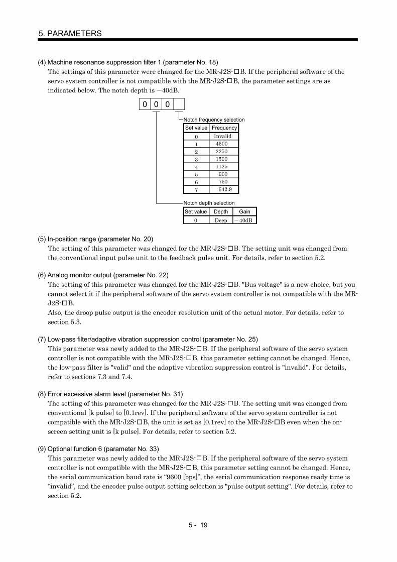
5 - 19
5. PARAMETERS
(4) Machine resonance suppression filter 1 (parameter No. 18)The settings of this parameter were changed for the MR-J2S- B. If the peripheral software of theservo system controller is not compatible with the MR-J2S- B, the parameter settings are asindicated below. The notch depth is 40dB.
0 0 0
01234567
Notch frequency selectionSet value Frequency
4500Invalid
225015001125900750642.9
Notch depth selectionSet value Depth Gain
0 Deep 40dB
(5) In-position range (parameter No. 20)The setting of this parameter was changed for the MR-J2S- B. The setting unit was changed fromthe conventional input pulse unit to the feedback pulse unit. For details, refer to section 5.2.
(6) Analog monitor output (parameter No. 22)The setting of this parameter was changed for the MR-J2S- B. "Bus voltage" is a new choice, but youcannot select it if the peripheral software of the servo system controller is not compatible with the MR-J2S- B.Also, the droop pulse output is the encoder resolution unit of the actual motor. For details, refer tosection 5.3.
(7) Low-pass filter/adaptive vibration suppression control (parameter No. 25)This parameter was newly added to the MR-J2S- B. If the peripheral software of the servo systemcontroller is not compatible with the MR-J2S- B, this parameter setting cannot be changed. Hence,the low-pass filter is "valid" and the adaptive vibration suppression control is "invalid". For details,refer to sections 7.3 and 7.4.
(8) Error excessive alarm level (parameter No. 31)The setting of this parameter was changed for the MR-J2S- B. The setting unit was changed fromconventional [k pulse] to [0.1rev]. If the peripheral software of the servo system controller is notcompatible with the MR-J2S- B, the unit is set as [0.1rev] to the MR-J2S- B even when the on-screen setting unit is [k pulse]. For details, refer to section 5.2.
(9) Optional function 6 (parameter No. 33)This parameter was newly added to the MR-J2S- B. If the peripheral software of the servo systemcontroller is not compatible with the MR-J2S- B, this parameter setting cannot be changed. Hence,the serial communication baud rate is “9600 [bps]”, the serial communication response ready time is“invalid”, and the encoder pulse output setting selection is "pulse output setting". For details, refer tosection 5.2.

5 - 20
5. PARAMETERS
MEMO

6 - 1
6. GENERAL GAIN ADJUSTMENT
6. GENERAL GAIN ADJUSTMENT
6.1 Different adjustment methods
6.1.1 Adjustment on a single servo amplifier
The gain adjustment in this section can be made on a single servo amplifier. For gain adjustment, firstexecute auto tuning mode 1. If you are not satisfied with the results, execute auto tuning mode 2, manualmode 1 and manual mode 2 in this order.
(1) Gain adjustment mode explanation
Gain adjustment modeParameter No. 8
settingEstimation of load inertia
moment ratioAutomatically set
parametersManually set parameters
Auto tuning mode 1(initial value)
0001 Always estimated GD2 (parameter No. 12)PG1 (parameter No. 13)VG1 (parameter No. 14)PG2 (parameter No. 15)VG2 (parameter No. 16)VIC (parameter No. 17)
RSP (parameter No. 9)
Auto tuning mode 2 0003 PG1 (parameter No. 13)VG1 (parameter No. 14)PG2 (parameter No. 15)VG2 (parameter No. 16)VIC (parameter No. 17)
GD2 (parameter No. 12)RSP (parameter No. 9)
Manual mode 1 0004 VG1 (parameter No. 14)PG2 (parameter No. 15)
GD2 (parameter No. 12)PG1 (parameter No. 13)VG2 (parameter No. 16)VIC (parameter No. 17)
Manual mode 2 0002
Fixed to parameter No.12 value
GD2 (parameter No. 12)PG1 (parameter No. 13)VG1 (parameter No. 14)PG2 (parameter No. 15)VG2 (parameter No. 16)VIC (parameter No. 17)
Interpolation mode 0000 Always estimated GD2 (parameter No. 12)PG2 (parameter No. 15)VG2 (parameter No. 16)VIC (parameter No. 17)
PG1 (parameter No. 13)VG1 (parameter No. 14)

6 - 2
6. GENERAL GAIN ADJUSTMENT
(2) Adjustment sequence and mode usage
UsageUsed when you want tomatch the position gain(PG1) between 2 or moreaxes. Normally not used forother purposes.Allows adjustment bymerely changing theresponse level setting.First use this mode to makeadjustment.Used when the conditions ofauto tuning mode 1 are notmet and the load inertiamoment ratio could not beestimated properly, forexample.
This mode permitsadjustment easily with threegains if you were notsatisfied with auto tuningresults.
END
Interpolation made for 2 or more
axes?
START
Operation
Auto tuning mode 2
OK?
Manual mode 1
OK?
Manual mode 2
OK?
OK?
No
No
Yes
No
Yes
No
Yes
No
Yes
Auto tuning mode 1
Operation
Interpolation mode
Operation
Operation
Yes
You can adjust all gainsmanually when you want todo fast settling or the like.

6 - 3
6. GENERAL GAIN ADJUSTMENT
6.1.2 Adjustment using MR Configurator (servo configuration software)
POINTWhen using the machine analyzer, set the servo amplifier's axis number for"F". (Refer to section 3.11.)
This section gives the functions and adjustment that may be performed by using the servo amplifier withthe MR Configurator (servo configuration software) which operates on a personal computer.
Function Description AdjustmentMachine analyzer With the machine and servo motor
coupled, the characteristic of themechanical system can be measured bygiving a random vibration command fromthe personal computer to the servo andmeasuring the machine response.
You can grasp the machine resonance frequency anddetermine the notch frequency of the machineresonance suppression filter.You can automatically set the optimum gains inresponse to the machine characteristic. This simpleadjustment is suitable for a machine which has largemachine resonance and does not require much settlingtime.
Gain search Executing gain search under to-and-fropositioning command measures settlingcharacteristic while simultaneouslychanging gains, and automaticallysearches for gains which make settlingtime shortest.
You can automatically set gains which makepositioning settling time shortest.
Machine simulation Response at positioning settling of amachine can be simulated from machineanalyzer results on personal computer.
You can optimize gain adjustment and commandpattern on personal computer.
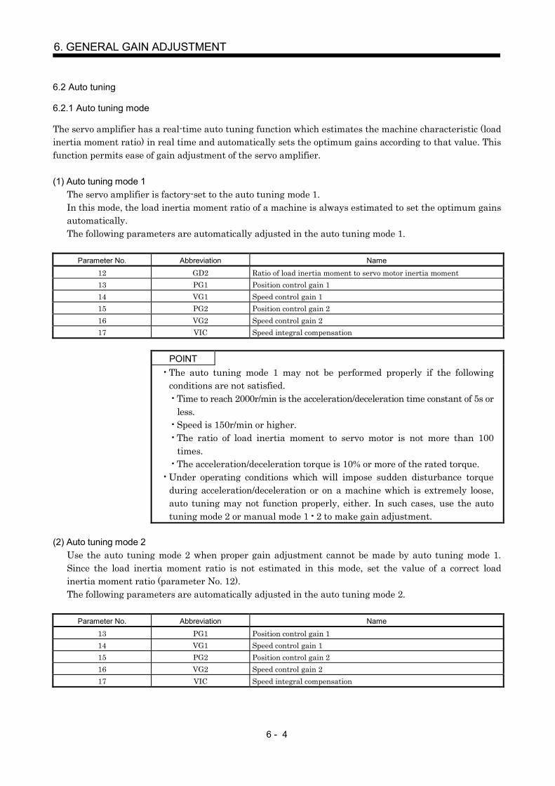
6 - 4
6. GENERAL GAIN ADJUSTMENT
6.2 Auto tuning
6.2.1 Auto tuning mode
The servo amplifier has a real-time auto tuning function which estimates the machine characteristic (loadinertia moment ratio) in real time and automatically sets the optimum gains according to that value. Thisfunction permits ease of gain adjustment of the servo amplifier.
(1) Auto tuning mode 1The servo amplifier is factory-set to the auto tuning mode 1.In this mode, the load inertia moment ratio of a machine is always estimated to set the optimum gainsautomatically.The following parameters are automatically adjusted in the auto tuning mode 1.
Parameter No. Abbreviation Name
12 GD2 Ratio of load inertia moment to servo motor inertia moment13 PG1 Position control gain 114 VG1 Speed control gain 115 PG2 Position control gain 216 VG2 Speed control gain 217 VIC Speed integral compensation
POINTThe auto tuning mode 1 may not be performed properly if the followingconditions are not satisfied.
Time to reach 2000r/min is the acceleration/deceleration time constant of 5s orless.Speed is 150r/min or higher.The ratio of load inertia moment to servo motor is not more than 100times.The acceleration/deceleration torque is 10% or more of the rated torque.
Under operating conditions which will impose sudden disturbance torqueduring acceleration/deceleration or on a machine which is extremely loose,auto tuning may not function properly, either. In such cases, use the autotuning mode 2 or manual mode 1 2 to make gain adjustment.
(2) Auto tuning mode 2Use the auto tuning mode 2 when proper gain adjustment cannot be made by auto tuning mode 1.Since the load inertia moment ratio is not estimated in this mode, set the value of a correct loadinertia moment ratio (parameter No. 12).The following parameters are automatically adjusted in the auto tuning mode 2.
Parameter No. Abbreviation Name
13 PG1 Position control gain 114 VG1 Speed control gain 115 PG2 Position control gain 216 VG2 Speed control gain 217 VIC Speed integral compensation

6 - 5
6. GENERAL GAIN ADJUSTMENT
6.2.2 Auto tuning mode operation
The block diagram of real-time auto tuning is shown below.
51
Servomotor
Command
Automatic setting
Control gainsPG1,VG1
PG2,VG2,VIC
Current control
Current feedback
Load inertia moment
Encoder
Position/speed feedback
Real-time auto tuning section
Speed feedback
Load inertia moment ratio
estimation section
Gain table
Parameter No.8
Auto tuning selectionResponse level setting
Parameter No.12Load inertia moment ratio estimation value
Set 0 or 1 to turn on.
Switch
Parameter No.9
When a servo motor is accelerated/decelerated, the load inertia moment ratio estimation section alwaysestimates the load inertia moment ratio from the current and speed of the servo motor. The results ofestimation are written to parameter No. 12 (the ratio of load inertia moment to servo motor). Theseresults can be confirmed on the status display screen of the MR Configurator (servo configurationsoftware) section.If the value of the load inertia moment ratio is already known or if estimation cannot be made properly,chose the "auto tuning mode 2" (parameter No. 8: 0003) to stop the estimation of the load inertia momentratio (Switch in above diagram turned off), and set the load inertia moment ratio (parameter No. 12)manually.From the preset load inertia moment ratio (parameter No. 12) value and response level (parameter No. 9),the optimum control gains are automatically set on the basis of the internal gain tale.The auto tuning results are saved in the EEP-ROM of the servo amplifier every 6 minutes since power-on.At power-on, auto tuning is performed with the value of each control gain saved in the EEP-ROM beingused as an initial value.
POINTIf sudden disturbance torque is imposed during operation, the estimation ofthe inertia moment ratio may malfunction temporarily. In such a case,choose the "auto tuning mode 2" (parameter No. 8: 0003) and set the correctload inertia moment ratio in parameter No. 12.When any of the auto tuning mode 1, auto tuning mode 2 and manual mode1 settings is changed to the manual mode 2 setting, the current controlgains and load inertia moment ratio estimation value are saved in the EEP-ROM.

6 - 6
6. GENERAL GAIN ADJUSTMENT
6.2.3 Adjustment procedure by auto tuning
Since auto tuning is made valid before shipment from the factory, simply running the servo motorautomatically sets the optimum gains that match the machine. Merely changing the response levelsetting value as required completes the adjustment. The adjustment procedure is as follows.
END
Yes
No
Yes
No
No
Yes
Auto tuning adjustment
Acceleration/deceleration repeated
Load inertia moment ratio estimation value stable?
Auto tuning conditions not satisfied.
(Estimation of load inertia moment ratio is difficult)
Adjust response level setting so that desired response is achieved on vibration-free level.
Acceleration/deceleration repeated
Requested performance satisfied?
To manual mode
Choose the auto tuning mode 2(parameter No. 8: 0003) and setthe load inertia moment ratio(parameter No. 12) manually.

6 - 7
6. GENERAL GAIN ADJUSTMENT
6.2.4 Response level setting in auto tuning mode
Set the response (parameter No. 9) of the whole servo system. As the response level setting is increased,the track ability and settling time for a command decreases, but a too high response level will generatevibration. Hence, make setting until desired response is obtained within the vibration-free range.If the response level setting cannot be increased up to the desired response because of machine resonancebeyond 100Hz, adaptive vibration suppression control (parameter No. 25) or machine resonancesuppression filter (parameter No. 18) may be used to suppress machine resonance. Suppressing machineresonance may allow the response level setting to increase. Refer to section 7.2, 7.3 for adaptive vibrationsuppression control and machine resonance suppression filter.
5Parameter No. 9
Response level setting
Machine characteristicResponse level setting
Machine rigidityMachine resonancefrequency guideline
Guideline of corresponding machine
1 Low 15Hz
2 20Hz
3 25Hz
4 30Hz
5 35Hz
6 45Hz
7 55Hz
8 Middle 70Hz
9 85Hz
A 105Hz
B 130Hz
C 160Hz
D 200Hz
E 240Hz
F High 300Hz
Large conveyor
Arm robot
General machine tool conveyor
Precision working machine
InserterMounterBonder

6 - 8
6. GENERAL GAIN ADJUSTMENT
6.3 Manual mode 1 (simple manual adjustment)
If you are not satisfied with the adjustment of auto tuning, you can make simple manual adjustment withthree parameters.
6.3.1 Operation of manual mode 1
In this mode, setting the three gains of position control gain 1 (PG1), speed control gain 2 (VG2) andspeed integral compensation (VIC) automatically sets the other gains to the optimum values according tothese gains.
PG1VG2VIC
PG2VG1
GD2
Automatic setting
User setting
Therefore, you can adjust the model adaptive control system in the same image as the general PI controlsystem (position gain, speed gain, speed integral time constant). Here, the position gain corresponds toPG1, the speed gain to VG2 and the speed integral time constant to VIC. When making gain adjustmentin this mode, set the load inertia moment ratio (parameter No. 12) correctly.
6.3.2 Adjustment by manual mode 1
POINTIf machine resonance occurs, adaptive vibration suppression control(parameter No. 25) or machine resonance suppression filter (parameter No.18) may be used to suppress machine resonance. (Refer to section 7.2, 7.3.)
(1) For speed control(a) Parameters
The following parameters are used for gain adjustment.
Parameter No. Abbreviation Name
12 GD2 Ratio of load inertia moment to servo motor inertia moment16 VG2 Speed control gain 217 VIC Speed integral compensation
(b) Adjustment procedure
Step Operation Description
1 Set an estimated value to the ratio of load inertia moment to servomotor inertia moment (parameter No. 12).
2Increase the speed control gain 2 (parameter No. 16) within thevibration- and unusual noise-free range, and return slightly if vibrationtakes place.
Increase the speed control gain.
3 Decrease the speed integral compensation (parameter No. 17) withinthe vibration-free range, and return slightly if vibration takes place.
Decrease the time constant of the speedintegral compensation.
4
If the gains cannot be increased due to mechanical system resonance orthe like and the desired response cannot be achieved, response may beincreased by suppressing resonance with adaptive vibrationsuppression control or machine resonance suppression filter and thenexecuting steps 2 and 3.
Suppression of machine resonanceRefer to section 7.2, 7.3.
5 While checking the settling characteristic and rotational status, fine-adjust each gain.
Fine adjustment

6 - 9
6. GENERAL GAIN ADJUSTMENT
(c) Adjustment description1) Speed control gain 2 (parameter No. 16)
This parameter determines the response level of the speed control loop. Increasing this valueenhances response but a too high value will make the mechanical system liable to vibrate. Theactual response frequency of the speed loop is as indicated in the following expression.
Speed loop response frequency(Hz) Speed control gain setting (1 ratio of load inertia moment to servo motor inertia moment) 2
2) Speed integral compensation (parameter No. 17)To eliminate stationary deviation against a command, the speed control loop is underproportional integral control. For the speed integral compensation, set the time constant of thisintegral control. Increasing the setting lowers the response level. However, if the load inertiamoment ratio is large or the mechanical system has any vibratory element, the mechanicalsystem is liable to vibrate unless the setting is increased to some degree. The guideline is asindicated in the following expression.
Speed integralcomposition setting (ms)
2000 to 3000Speed control gain 2 setting/ (1 ratio of load inertia moment
to servo motor inertia moment.)
(2) For position control(a) Parameters
The following parameters are used for gain adjustment.
Parameter No. Abbreviation Name
12 GD2 Ratio of load inertia moment to servo motor inertia moment13 PG1 Position control gain 116 VG2 Speed control gain 217 VIC Speed integral compensation
(b) Adjustment procedureStep Operation Description
1Set an estimated value to the ratio of load inertia moment to servomotor inertia moment (parameter No. 12).
2Set a slightly smaller value to the position control gain 1 (parameterNo. 13).
3Increase the speed control gain 2 (parameter No. 16) within thevibration- and unusual noise-free range, and return slightly if vibrationtakes place.
Increase the speed control gain.
4Decrease the speed integral compensation (parameter No. 17) withinthe vibration-free range, and return slightly if vibration takes place.
Decrease the time constant of the speedintegral compensation.
5 Increase the position control gain 1 (parameter No. 13). Increase the position control gain.
6
If the gains cannot be increased due to mechanical system resonance orthe like and the desired response cannot be achieved, response may beincreased by suppressing resonance with adaptive vibrationsuppression control or machine resonance suppression filter and thenexecuting steps 3 to 5.
Suppression of machine resonanceRefer to section 7.2 and 7.3.
7While checking the settling characteristic and rotational status, fine-adjust each gain.
Fine adjustment

6 - 10
6. GENERAL GAIN ADJUSTMENT
(c) Adjustment description1) Position control gain 1 (parameter No. 13)
This parameter determines the response level of the position control loop. Increasing positioncontrol gain 1 improves track ability to a position command but a too high value will makeovershooting liable to occur at the time of settling.
Position controlgain 1 guideline
Speed control gain 2 setting (1 ratio of load inertia moment to servo motor inertia moment) ( to
15
13 )
2) Speed control gain 2 (parameter No. 16)This parameter determines the response level of the speed control loop. Increasing this valueenhances response but a too high value will make the mechanical system liable to vibrate. Theactual response frequency of the speed loop is as indicated in the following expression.
Speed loop responsefrequency(Hz)
Speed control gain 2 setting (1 ratio of load inertia moment to servo motor inertia moment) 22
3) Speed integral compensation (parameter No. 17)To eliminate stationary deviation against a command, the speed control loop is underproportional integral control. For the speed integral compensation, set the time constant of thisintegral control. Increasing the setting lowers the response level. However, if the load inertiamoment ratio is large or the mechanical system has any vibratory element, the mechanicalsystem is liable to vibrate unless the setting is increased to some degree. The guideline is asindicated in the following expression.
Speed integral compensation setting(ms)
2000 to 3000Speed control gain 2 setting/ (1 ratio of load inertia moment to
servo motor inertia moment set value)

6 - 11
6. GENERAL GAIN ADJUSTMENT
6.4 Interpolation mode
The interpolation mode is used to match the position control gains of the axes when performing theinterpolation operation of servo motors of two or more axes for an X-Y table or the like. In this mode, theposition control gain 1 and speed control gain 1 which determine command track ability are set manuallyand the other gain adjusting parameters are set automatically.
(1) Parameter(a) Automatically adjusted parameters
The following parameters are automatically adjusted by auto tuning.Parameter No. Abbreviation Name
12 GD2 Ratio of load inertia moment to servo motor inertia moment15 PG2 Position control gain 216 VG2 Speed control gain 217 VIC Speed integral compensation
(b) Manually adjusted parametersThe following parameters are adjustable manually.
Parameter No. Abbreviation Name
13 PG1 Position control gain 114 VG1 Speed control gain 1
(2) Adjustment procedure
Step Operation Description
1Choose the auto tuning mode 1 (parameter No. 8: 0001) and set the machineresonance frequency of the response level to 15Hz 1 (parameter No. 9: 0001).
Select the auto tuning mode 1.
2During operation, increase the response level selection (parameter No. 9), andreturn the setting if vibration occurs.
Adjustment in auto tuning mode1.
3Check the values of position control gain 1 (parameter No. 13) and speed controlgain 1 (parameter No. 14).
Check the upper setting limits.
4 Choose the interpolation mode (parameter No. 8: 0000). Select the interpolation mode.
5Set the position control gain 1 of all the axes to be interpolated to the samevalue. At that time, adjust to the setting value of the axis, which has thesmallest position control gain 1.
Set position control gain 1.
6Using the speed control gain 1 value checked in step 3 as the guideline of theupper limit, look at the rotation status and set in speed control gain 1 the valuethree or more times greater than the position control gain 1 setting.
Set speed control gain 1.
7Looking at the interpolation characteristic and rotation status, fine-adjust thegains and response level setting.
Fine adjustment.
(3) Adjustment description(a) Position control gain 1 (parameter No.13)
This parameter determines the response level of the position control loop. Increasing PG1 improvestrack ability to a position command but a too high value will make overshooting liable to occur atthe time of settling. The droop pulse value is determined by the following expression.
Droop pulse value (pulse) Position control gain set value60
Rotation speed (r/min) 131,072(pulse)
(b) Speed control gain 1 (parameter No. 14)Set the response level of the speed loop of the model. Make setting using the following expressionas a guideline.Speed control gain 1 setting Position control gain 1 setting 3

6 - 12
6. GENERAL GAIN ADJUSTMENT
6.5 Differences in auto tuning between MELSERVO-J2 and MELSERVO-J2-Super
6.5.1 Response level setting
To meet higher response demands, the MELSERVO-J2-Super series has been changed in response levelsetting range from the MELSERVO-J2 series. The following table lists comparison of the response levelsetting.
Response level setting
Parameter No. 9
5
MELSERVO-J2 series MELSERVO-J2-Super seriesResponse level setting Machine resonance frequency Response level setting Machine resonance frequency guideline
1 15Hz1 20Hz 2 20Hz
3 25Hz4 30Hz5 35Hz
2 40Hz 6 45Hz7 55Hz
3 60Hz 8 70Hz4 80Hz 9 85Hz5 100Hz A 105Hz
B 130HzC 160HzD 200HzE 240HzF 300Hz
Note that because of a slight difference in gain adjustment pattern, response may not be the same if theresonance frequency is set to the same value.
6.5.2 Auto tuning selection
The MELSERVO-J2-Super series has an addition of the load inertia moment ratio fixing mode. It also hasthe addition of the manual mode 1 which permits manual adjustment with three parameters.
1Parameter No. 8
Gain adjustment mode selection
Auto tuning selectionGain adjustment mode
MELSERVO-J2 series MELSERVO-J2-Super seriesRemarks
Interpolation mode 0 0 Position control gain 1 is fixed.Auto tuning mode 1 1 1 Ordinary auto tuning
Auto tuningAuto tuning mode 2 3
Estimation of load inertia momentratio stopped.Response level setting valid.
Manual mode 1 4 Simple manual adjustmentAuto tuninginvalid Manual mode 2 2 2 Manual adjustment of all gains

7 - 1
7. SPECIAL ADJUSTMENT FUNCTIONS
7. SPECIAL ADJUSTMENT FUNCTIONS
POINTThe functions given in this chapter need not be used generally. Use them ifyou are not satisfied with the machine status after making adjustment inthe methods in chapter 6.
If a mechanical system has a natural resonance point, increasing the servo system response level maycause the mechanical system to produce resonance (vibration or unusual noise) at that resonancefrequency.Using the machine resonance suppression filter and adaptive vibration suppression control functions cansuppress the resonance of the mechanical system.
7.1 Function block diagram
Speedcontrol
Encoder
Current command
Low-passfilter
ParameterNo.18
ParameterNo.25
ParameterNo.25
Machine resonance suppression filter 1
Adaptive vibration suppression control
00
or1 2
0 0
1
00except
Servomotor
7.2 Machine resonance suppression filter
(1) FunctionThe machine resonance suppression filter is a filter function (notch filter) which decreases the gain ofthe specific frequency to suppress the resonance of the mechanical system. You can set the gaindecreasing frequency (notch frequency) and gain decreasing depth.
Mechanical system responselevel
Machine resonance point
Frequency
Notch depth
Notch frequencyFrequency
POINTThe machine resonance suppression filter is a delay factor for the servosystem. Hence, vibration may increase if you set a wrong resonancefrequency or a too deep notch.

7 - 2
7. SPECIAL ADJUSTMENT FUNCTIONS
(2) ParametersSet the notch frequency and notch depth of the machine resonance suppression filter 1 (parameter No.18).
3
12
0
0001
020304050607
Invalid45002250
0809
0A0B0C0D0E0F
1011
121314151617
1819
1A1B1C1D1E1F
15001125
900750642.9
500450409.1
375346.2321.4
300
562.5 281.3264.7
250236.8
225214.3204.5195.7
187.5180173.1166.7160.1155.2150145.2
Setting FrequencySetting Frequency Setting Frequency Setting Frequency
Parameter No. 18
Notch frequency selection
Notch depth selection
Setting Depth (Gain)Deep ( 40dB)
Shallow ( 4dB)
( 14dB) ( 8dB)
POINTIf the frequency of machine resonance is unknown, decrease the notchfrequency from higher to lower ones in order. The optimum notch frequencyis set at the point where vibration is minimal.A deeper notch has a higher effect on machine resonance suppression butincreases a phase delay and may increase vibration.The machine characteristic can be grasped beforehand by the machineanalyzer on the MR Configurator (servo configuration software). Thisallows the required notch frequency and depth to be determined.
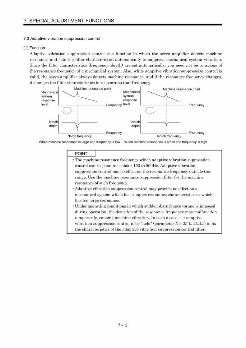
7 - 3
7. SPECIAL ADJUSTMENT FUNCTIONS
7.3 Adaptive vibration suppression control
(1) FunctionAdaptive vibration suppression control is a function in which the servo amplifier detects machineresonance and sets the filter characteristics automatically to suppress mechanical system vibration.Since the filter characteristics (frequency, depth) are set automatically, you need not be conscious ofthe resonance frequency of a mechanical system. Also, while adaptive vibration suppression control isvalid, the servo amplifier always detects machine resonance, and if the resonance frequency changes,it changes the filter characteristics in response to that frequency.
Mechanical system responselevel
Mechanical system responselevel
Machine resonance point Machine resonance point
Frequency Frequency
Notch depth
Notch depth
Notch frequency Notch frequencyFrequency Frequency
When machine resonance is large and frequency is low When machine resonance is small and frequency is high
POINTThe machine resonance frequency which adaptive vibration suppressioncontrol can respond to is about 150 to 500Hz. Adaptive vibrationsuppression control has no effect on the resonance frequency outside thisrange. Use the machine resonance suppression filter for the machineresonance of such frequency.Adaptive vibration suppression control may provide no effect on amechanical system which has complex resonance characteristics or whichhas too large resonance.Under operating conditions in which sudden disturbance torque is imposedduring operation, the detection of the resonance frequency may malfunctiontemporarily, causing machine vibration. In such a case, set adaptivevibration suppression control to be "held" (parameter No. 25: 2 ) to fixthe characteristics of the adaptive vibration suppression control filter.

7 - 4
7. SPECIAL ADJUSTMENT FUNCTIONS
(2) ParametersThe operation of adaptive vibration suppression control selection (parameter No. 25).
Parameter No. 25
Adaptive vibration suppression control selection0: Invalid1: Valid
Machine resonance frequency is always detected to generate the filter in response to resonance, suppressing machine vibration.
2: Held
Adaptive vibration suppression control sensitivity selectionSet the sensitivity of detecting machine resonance.0: Normal1: Large sensitivity
Filter characteristics generated so far is held, and detection ofmachine resonance is stopped.
POINTAdaptive vibration suppression control is factory-set to be "invalid"(parameter No. 25: 0000).Selection the adaptive vibration suppression control sensitivity can changethe sensitivity of detecting machine resonance. Selection of "largesensitivity" detects smaller machine resonance and generates a filter tosuppress machine vibration. However, since a phase delay will alsoincrease, the response of the servo system may not increase.
7.4 Low-pass filter
(1) FunctionWhen a ball screw or the like is used, resonance of high frequency may occur as the response level ofthe servo system is increased. To prevent this, the low-pass filter is factory-set to be valid for a torquecommand. The filter frequency of this low-pass filter is automatically adjusted to the value in thefollowing expression.
Filter frequency(Hz)
Speed control gain 2 set value 10 (1 ratio of load inertia moment to servo motor inertia moment set value 0.1)2
(2) ParameterSet the operation of the low-pass filter (parameter No. 25).
Parameter No. 25
Low-pass filter selection0: Valid (automatic adjustment) initial value1: Invalid
POINTIn a mechanical system where rigidity is extremely high and resonance isdifficult to occur, setting the low-pass filter to be "invalid" may increase theservo system response to shorten the settling time.

7 - 5
7. SPECIAL ADJUSTMENT FUNCTIONS
7.5 Gain changing function
This function can change the gains. You can change between gains during rotation and gains during stopor can use an external signal to change gains during operation.
7.5.1 Applications
This function is used when.
(1) You want to increase the gains during servo lock but decrease the gains to reduce noise during rotation.
(2) You want to increase the gains during settling to shorten the stop settling time.
(3) You want to change the gains using an external signal to ensure stability of the servo system since theload inertia moment ratio varies greatly during a stop (e.g. a large load is mounted on a carrier).
7.5.2 Function block diagram
The valid control gains PG2, VG2, VIC and GD2 of the actual loop are changed according to the conditionsselected by gain changing selection CDP (parameter No. 49) and gain changing condition CDS (parameterNo. 50).
Valid GD2 value
Command pulse frequency
Droop pulses
Model speed
Control command of controller
Comparator
Valid PG2 value
Valid VG2 value
Valid VIC value
Changing
PG2 PG2B100
VIC VICB100
VG2 VG2B100
GD2BParameter No.52
GD2Parameter No.12
PG2Parameter No.15
VG2Parameter No.16
VICParameter No.17
CDPParameter No.49
CDSParameter No.50
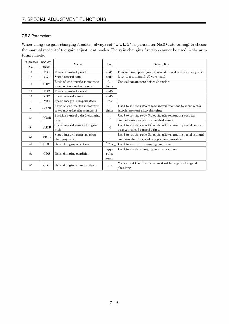
7 - 6
7. SPECIAL ADJUSTMENT FUNCTIONS
7.5.3 Parameters
When using the gain changing function, always set " 2 " in parameter No.8 (auto tuning) to choosethe manual mode 2 of the gain adjustment modes. The gain changing function cannot be used in the autotuning mode.
ParameterNo.
Abbreviation
Name Unit Description
13 PG1 Position control gain 1 rad/s14 VG1 Speed control gain 1 rad/s
Position and speed gains of a model used to set the responselevel to a command. Always valid.
12 GD2Ratio of load inertia moment toservo motor inertia moment
0.1times
15 PG2 Position control gain 2 rad/s16 VG2 Speed control gain 2 rad/s17 VIC Speed integral compensation ms
Control parameters before changing
52 GD2BRatio of load inertia moment toservo motor inertia moment 2
0.1times
Used to set the ratio of load inertia moment to servo motorinertia moment after changing.
53 PG2BPosition control gain 2 changingratio
%Used to set the ratio (%) of the after-changing positioncontrol gain 2 to position control gain 2.
54 VG2BSpeed control gain 2 changingratio
%Used to set the ratio (%) of the after-changing speed controlgain 2 to speed control gain 2.
55 VICBSpeed integral compensationchanging ratio
%Used to set the ratio (%) of the after-changing speed integralcompensation to speed integral compensation.
49 CDP Gain changing selection Used to select the changing condition.
50 CDS Gain changing conditionkppspulser/min
Used to set the changing condition values.
51 CDT Gain changing time constant msYou can set the filter time constant for a gain change atchanging.

7 - 7
7. SPECIAL ADJUSTMENT FUNCTIONS
(1) Parameters No. 12 to 17These parameters are the same as in ordinary manual adjustment. Gain changing allows the values ofratio of load inertia moment to servo motor inertia moment, position control gain 2, speed control gain2 and speed integral compensation to be changed.
(2) Ratio of load inertia moment to servo motor inertia moment 2 (parameter No. 52)Set the ratio of load inertia moment to servo motor inertia moment after changing. If the load inertiamoment ratio does not change, set it to the same value as ratio of load inertia moment to servo motorinertia moment (parameter No. 34).
(3) Position control gain 2 changing ratio (parameter No. 53), speed control gain 2 changing ratio (parameterNo. 54), speed integral compensation changing ratio (parameter No. 55)Set the values of after-changing position control gain 2, speed control gain 2 and speed integralcompensation in ratio (%). 100% setting means no gain change.For example, at the setting of position control gain 2 100, speed control gain 2 2000, speed integralcompensation 20 and position control gain 2 changing ratio 180%, speed control gain 2 changingratio 150% and speed integral compensation changing ratio 80%, the after-changing values are asfollows.Position control gain 2 Position control gain 2 Position control gain 2 changing ratio /100 180rad/sSpeed control gain 2 Speed control gain 2 Speed control gain 2 changing ratio /100 3000rad/sSpeed integral compensation Speed integral compensation Speed integral compensation changingratio /100 16ms
(4) Gain changing selection (parameter No. 49)Used to set the gain changing condition. Choose the changing condition in the first digit. If setting "1"here, the gain changing can be switched with the control command of controller.
Parameter No. 49
Gain changing selectionGains are changed in accordance with the settings of parameters No. 52 to 55 under any of the following conditions:0: Invalid1: Control command of controller2: Command frequency is equal to higher than parameter No. 50 setting3: Droop pulse value is equal to higher than parameter No. 50 setting4: Servo motor speed is equal to higher than parameter No. 50 setting
(5) Gain changing condition (parameter No. 50)When you selected "command frequency", "droop pulses" or "servo motor speed" in gain changingselection (parameter No.50), set the gain changing level.The setting unit is as follows.
Gain changing condition Unit
Command frequency kppsDroop pulses pulse
Servo motor speed r/min
(6) Gain changing time constant (parameter No. 51)You can set the primary delay filter to each gain at gain changing. This parameter is used to suppressshock given to the machine if the gain difference is large at gain changing, for example.

7 - 8
7. SPECIAL ADJUSTMENT FUNCTIONS
7.5.4 Gain changing operation
This operation will be described by way of setting examples.
(1) When you choose changing by external input(a) Setting
Parameter No. Abbreviation Name Setting Unit
13 PG1 Position control gain 1 100 rad/s14 VG1 Speed control gain 1 1000 rad/s
12 GD2Ratio of load inertia moment toservo motor inertia moment
4 0.1 times
15 PG2 Position control gain 2 120 rad/s16 VG2 Speed control gain 2 3000 rad/s17 VIC Speed integral compensation 20 ms
52 GD2BRatio of load inertia moment toservo motor inertia moment 2
100 0.1 times
53 PG2BPosition control gain 2changing ratio
70 %
54 VG2BSpeed control gain 2 changingratio
133 %
55 VICBSpeed integral compensationchanging ratio
250 %
49 CDP Gain changing selection0001
Control command fromcontroller
51 CDT Gain changing time constant 100 ms
(b) Changing operationOFF ON OFFControl command
from controller(CDP)
Change of each gain
Before-changing gain
After-changing gain
CDT 100ms
Position control gain 1 100Speed control gain 1 1000Ratio of load inertia momentto servo motor inertia moment
4.0 10.0 4.0
Position control gain 2 120 84 120Speed control gain 2 3000 4000 3000Speed integral compensation 20 50 20

7 - 9
7. SPECIAL ADJUSTMENT FUNCTIONS
(2) When you choose changing by droop pulses(a) Setting
Parameter No. Abbreviation Name Setting Unit
13 PG1 Position control gain 1 100 rad/s14 VG1 Speed control gain 1 1000 rad/s
12 GD2Ratio of load inertia moment toservo motor inertia moment
40 0.1 times
15 PG2 Position control gain 2 120 rad/s16 VG2 Speed control gain 2 3000 rad/s17 VIC Speed integral compensation 20 ms
52 GD2BRatio of load inertia moment toservo motor inertia moment 2
100 0.1 times
53 PG2BPosition control gain 2changing ratio
70 %
54 VG2BSpeed control gain 2 changingratio
133 %
55 VICBSpeed integral compensationchanging ratio
250 %
49 CDP Gain changing selection0003
(Changed by droop pulses)50 CDS Gain changing condition 50 pulse51 CDT Gain changing time constant 100 ms
(b) Changing operation
CDT 100ms
0Droop pulses [pulses]
Change of each gain
CDS
CDS
Before-changing gain
After-changing gain
Command pulse Droop pulses
Position control gain 1 100Speed control gain 1 1000Ratio of load inertia momentto servo motor inertia moment
4.0 10.0 4.0 10.0
Position control gain 2 120 84 120 84Speed control gain 2 3000 4000 3000 4000Speed integral compensation 20 50 20 50

7 - 10
7. SPECIAL ADJUSTMENT FUNCTIONS
MEMO

8 - 1
8. INSPECTION
8. INSPECTION
WARNING
Before starting maintenance and/or inspection, turn off the power and wait for 15minutes or more until the charge lamp turns off. Then, confirm that the voltagebetween P and N is safe with a voltage tester and others. Otherwise, an electricshock may occur. In addition, always confirm from the front of the servo amplifierwhether the charge lamp is off or not.Any person who is involved in inspection should be fully competent to do the work.Otherwise, you may get an electric shock. For repair and parts replacement,contact your safes representative.
POINTDo not test the servo amplifier with a megger (measure insulationresistance), or it may become faulty.Do not disassemble and/or repair the equipment on customer side.
(1) InspectionIt is recommended to make the following checks periodically.
(a) Check for loose terminal block screws. Retighten any loose screws.
(b) Check the cables and the like for scratches and cracks. Perform periodic inspection according tooperating conditions.
(2) LifeThe following parts must be changed periodically as listed below. If any part is found faulty, it must bechanged immediately even when it has not yet reached the end of its life, which depends on theoperating method and environmental conditions. For parts replacement, please contact your salesrepresentative.
Part name Life guideline
Smoothing capacitor 10 years
RelayNumber of power-on and number of forcedstop times:100,000times.
Cooling fan 10,000 to 30,000hours (2 to 3 years)Servo amplifier
Absolute position battery Refer to section 13.2
(a) Smoothing capacitorAffected by ripple currents, etc. and deteriorates in characteristic. The life of the capacitor greatlydepends on ambient temperature and operating conditions. The capacitor will reach the end of itslife in 10 years of continuous operation in normal air-conditioned environment.
(b) RelaysTheir contacts will wear due to switching currents and contact faults occur. Relays reach the end oftheir life when the cumulative number of power-on and forced stop times is 100,000, which dependson the power supply capacity.
(c) Servo amplifier cooling fanThe cooling fan bearings reach the end of their life in 10,000 to 30,000 hours. Normally, therefore,the cooling fan must be changed in a few years of continuous operation as a guideline.It must also be changed if unusual noise or vibration is found during inspection.

8 - 2
8. INSPECTION
MEMO
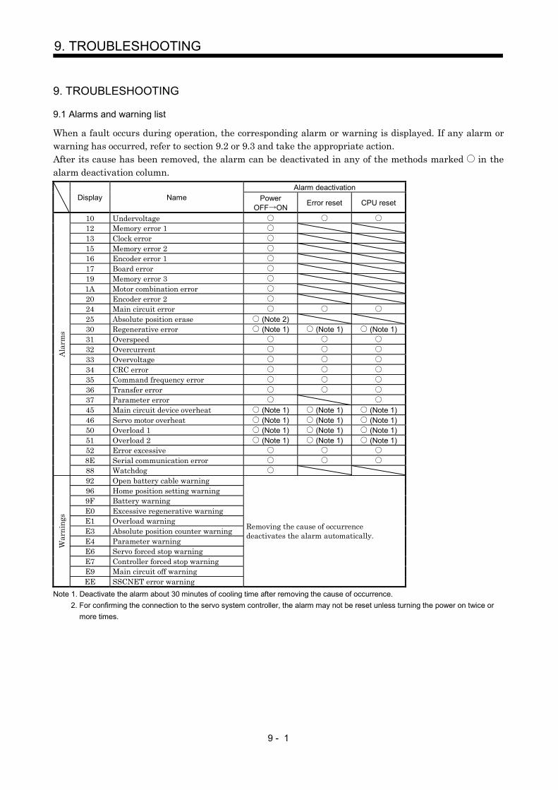
9 - 1
9. TROUBLESHOOTING
9. TROUBLESHOOTING
9.1 Alarms and warning list
When a fault occurs during operation, the corresponding alarm or warning is displayed. If any alarm orwarning has occurred, refer to section 9.2 or 9.3 and take the appropriate action.After its cause has been removed, the alarm can be deactivated in any of the methods marked in thealarm deactivation column.
Alarm deactivationDisplay Name Power
OFF ON Error reset CPU reset
10 Undervoltage12 Memory error 113 Clock error15 Memory error 216 Encoder error 117 Board error19 Memory error 31A Motor combination error20 Encoder error 224 Main circuit error25 Absolute position erase (Note 2)30 Regenerative error (Note 1) (Note 1) (Note 1)31 Overspeed32 Overcurrent33 Overvoltage34 CRC error35 Command frequency error36 Transfer error37 Parameter error45 Main circuit device overheat (Note 1) (Note 1) (Note 1)46 Servo motor overheat (Note 1) (Note 1) (Note 1)50 Overload 1 (Note 1) (Note 1) (Note 1)51 Overload 2 (Note 1) (Note 1) (Note 1)52 Error excessive8E Serial communication error
Ala
rms
88 Watchdog92 Open battery cable warning96 Home position setting warning9F Battery warningE0 Excessive regenerative warningE1 Overload warningE3 Absolute position counter warningE4 Parameter warningE6 Servo forced stop warningE7 Controller forced stop warningE9 Main circuit off warning
War
ning
s
EE SSCNET error warning
Removing the cause of occurrencedeactivates the alarm automatically.
Note 1. Deactivate the alarm about 30 minutes of cooling time after removing the cause of occurrence.2. For confirming the connection to the servo system controller, the alarm may not be reset unless turning the power on twice or
more times.
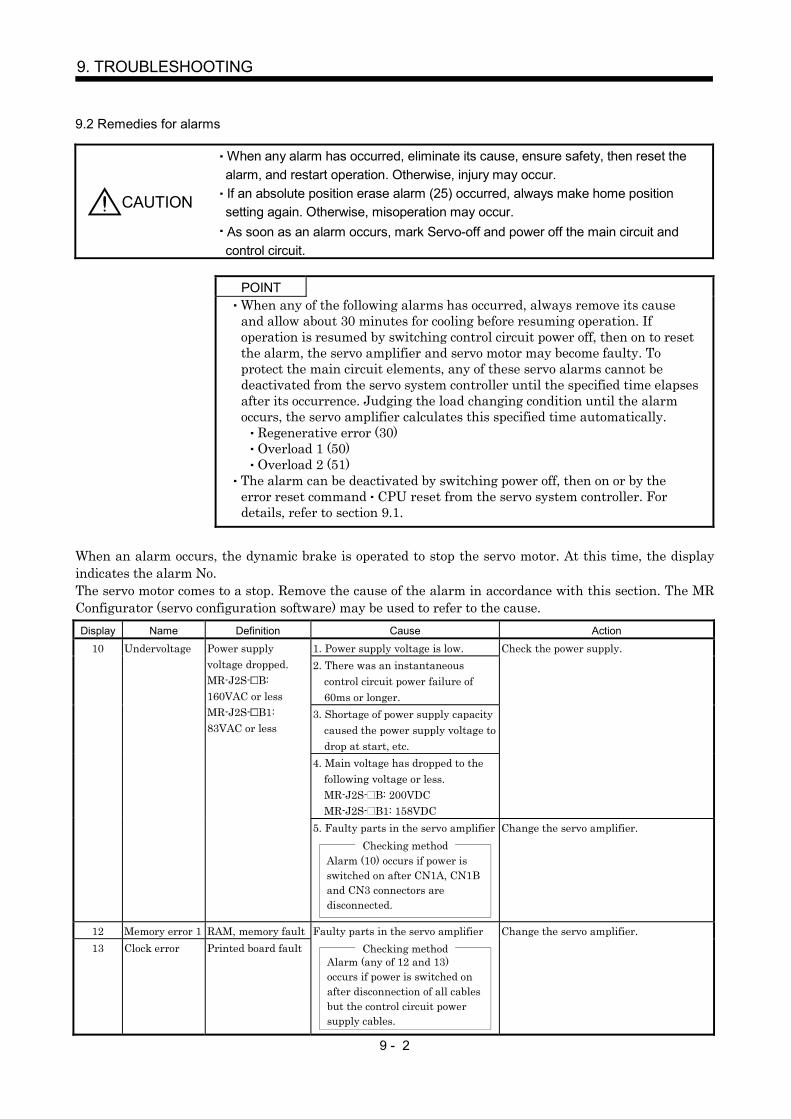
9 - 2
9. TROUBLESHOOTING
9.2 Remedies for alarms
CAUTION
When any alarm has occurred, eliminate its cause, ensure safety, then reset thealarm, and restart operation. Otherwise, injury may occur.If an absolute position erase alarm (25) occurred, always make home positionsetting again. Otherwise, misoperation may occur.As soon as an alarm occurs, mark Servo-off and power off the main circuit andcontrol circuit.
POINTWhen any of the following alarms has occurred, always remove its causeand allow about 30 minutes for cooling before resuming operation. Ifoperation is resumed by switching control circuit power off, then on to resetthe alarm, the servo amplifier and servo motor may become faulty. Toprotect the main circuit elements, any of these servo alarms cannot bedeactivated from the servo system controller until the specified time elapsesafter its occurrence. Judging the load changing condition until the alarmoccurs, the servo amplifier calculates this specified time automatically.
Regenerative error (30)Overload 1 (50)Overload 2 (51)
The alarm can be deactivated by switching power off, then on or by theerror reset command CPU reset from the servo system controller. Fordetails, refer to section 9.1.
When an alarm occurs, the dynamic brake is operated to stop the servo motor. At this time, the displayindicates the alarm No.The servo motor comes to a stop. Remove the cause of the alarm in accordance with this section. The MRConfigurator (servo configuration software) may be used to refer to the cause.Display Name Definition Cause Action
1. Power supply voltage is low.2. There was an instantaneous
control circuit power failure of60ms or longer.
3. Shortage of power supply capacitycaused the power supply voltage todrop at start, etc.
4. Main voltage has dropped to thefollowing voltage or less.MR-J2S- B: 200VDCMR-J2S- B1: 158VDC
Check the power supply.10 Undervoltage Power supplyvoltage dropped.MR-J2S- B:160VAC or lessMR-J2S- B1:83VAC or less
5. Faulty parts in the servo amplifierChecking method
Alarm (10) occurs if power isswitched on after CN1A, CN1Band CN3 connectors aredisconnected.
Change the servo amplifier.
12 Memory error 1 RAM, memory fault13 Clock error Printed board fault
Faulty parts in the servo amplifierChecking method
Alarm (any of 12 and 13) occurs if power is switched onafter disconnection of all cables but the control circuit power supply cables.
Change the servo amplifier.

9 - 3
9. TROUBLESHOOTING
Display Name Definition Cause Action
1. Faulty parts in the servo amplifierChecking method
Alarm (15) occurs if power is switched on after disconnection of all cables but the control circuit power supply cables.
15 Memory error 2 EEP-ROM fault
2. The number of write times to EEP-ROM exceeded 100,000.
Change the servo amplifier.
1. Encoder connector (CN2)disconnected.
Connect correctly.
2. Encoder fault Change the servo motor.
16 Encoder error 1 Communicationerror occurredbetween encoderand servo amplifier. 3. Encoder cable faulty
(Wire breakage or shorted)Repair or change the cable.
CPU/parts fault 1. Faulty parts in the servo amplifierChecking method
Alarm (17) occurs if power is switched on after disconnection of all cable but the control circuit power supply cable.
Change the servo amplifier.17 Board error
The outputterminals U, V, W ofthe servo amplifierand the inputterminals U, V, W ofthe servo motor arenot connected.
2. The wiring of U, V, W isdisconnected or not connected.
Correctly connect the output terminals U,V, W of the servo amplifier and the inputterminals U, V, W of the servo motor.
19 Memory error 3 ROM memory fault Faulty parts in the servo amplifierChecking method
Alarm (19) occurs if power is switched on after disconnection of all cable but the control circuit power supply cable.
Change the servo amplifier.
1A Motorcombinationerror
Wrong combinationof servo amplifierand servo motor.
Wrong combination of servoamplifier and servo motor connected.
Use correct combination.
1. Encoder connector (CN2)disconnected.
Connect correctly.
2. Encoder fault Change the servo motor.
Communicationerror occurredbetween encoderand servo amplifier. 3. Encoder cable faulty
(Wire breakage or shorted)Repair or change the cable.
20 Encoder error 2
Encoder detectedacceleration error.
4. Excessive acceleration is occurreddue to oscillation and others.
1. Decrease the speed control gain 2.2. Decrease the auto tuning response level.
1. Power input wires and servo motoroutput wires are in contact atmain circuit terminal block (TE1).
Connect correctly.
2. Sheathes of servo motor powercables deteriorated, resulting inground fault.
Change the cable.
24 Main circuiterror
Ground faultoccurred at theservo motor outputs(U,V and W phases)of the servoamplifier.
3. Main circuit of servo amplifierfailed.
Checking methodAlarm (24) occurs if the servo isswitched on after disconnectingthe U, V, W power cables fromthe servo amplifier.
Change the servo amplifier.
1. Battery voltage lowAbsolute positiondata in error 2. Battery cable or battery is faulty.
Change the battery.Always make home position setting again.
25 Absoluteposition erase
Power was switchedon for the first timein the absoluteposition detectionsystem.
3. Super capacitor of the absoluteposition encoder is not charged.
After leaving the alarm occurring for a fewminutes, switch power off, then on again.Always make home position setting again.

9 - 4
9. TROUBLESHOOTING
Display Name Definition Cause Action1. Mismatch between used
regenerative option andparameter No. 2 setting
Set correctly.
2. Built-in regenerative resistor orregenerative option is notconnected.
Connect correctly.
3. High-duty operation or continuousregenerative operation caused thepermissible regenerative power ofthe regenerative option to beexceeded.
Checking methodCall the status display and checkthe regenerative load ratio.
1. Reduce the frequency of positioning.2. Use the regenerative option of larger
capacity.3. Reduce the load.
4. Power supply voltage is abnormal.MR-J2S- B:260VAC or moreMR-J2S- B1:135VAC or more
Review power supply
Permissibleregenerative powerof the built-inregenerativeresistor orregenerative optionis exceeded.
5. Built-in regenerative resistor orregenerative option faulty.
Change the servo amplifier orregenerative option.
30 Regenerativeerror
Regenerativetransistor fault
6. Regenerative transistor faulty.Checking method
1) The regenerative option has overheated abnormally.2) The alarm occurs even after removal of the built-in regenerative resistor or regenerative option.
Change the servo amplifier.
1. Small acceleration/decelerationtime constant caused overshoot tobe large.
Increase acceleration/deceleration timeconstant.
2. Servo system is instable to causeovershoot.
1. Reset servo gain to proper value.2. If servo gain cannot be set to proper
value.1) Reduce load inertia moment ratio; or2) Reexamine acceleration/
deceleration time constant.
31 Overspeed Speed has exceededthe instantaneouspermissible speed.
3. Encoder faulty. Change the servo motor.1. Short occurred in servo amplifier
output phases U, V and W.Correct the wiring.
2. Transistor of the servo amplifierfaulty.
Checking methodAlarm (32) occurs if power isswitched on after U,V and Ware disconnected.
Change the servo amplifier.
3. Ground fault occurred in servoamplifier output phases U, V andW.
Correct the wiring.
32 Overcurrent Current that flew ishigher than thepermissible currentof the servoamplifier. (Whenthe alarm (32)occurs, switch thepower OFF andthen ON to reset thealarm. Then, turnon the servo-on.When the alarm (32)still occurs at thetime, the transistor(IPM IGBT) of theservo amplifier maybe at fault. Do notswitch the powerOFF/ON repeatedly;check the transistoraccording to thecause 2 checkingmethod.)
4. External noise caused theovercurrent detection circuit tomisoperate.
Take noise suppression measures.
Current higher thanthe permissiblecurrent flew in theregenerativetransistor.(MR-J2S-500B only)
5. Improper wiring of theregenerative option.
Wire the regenerative option correctly.
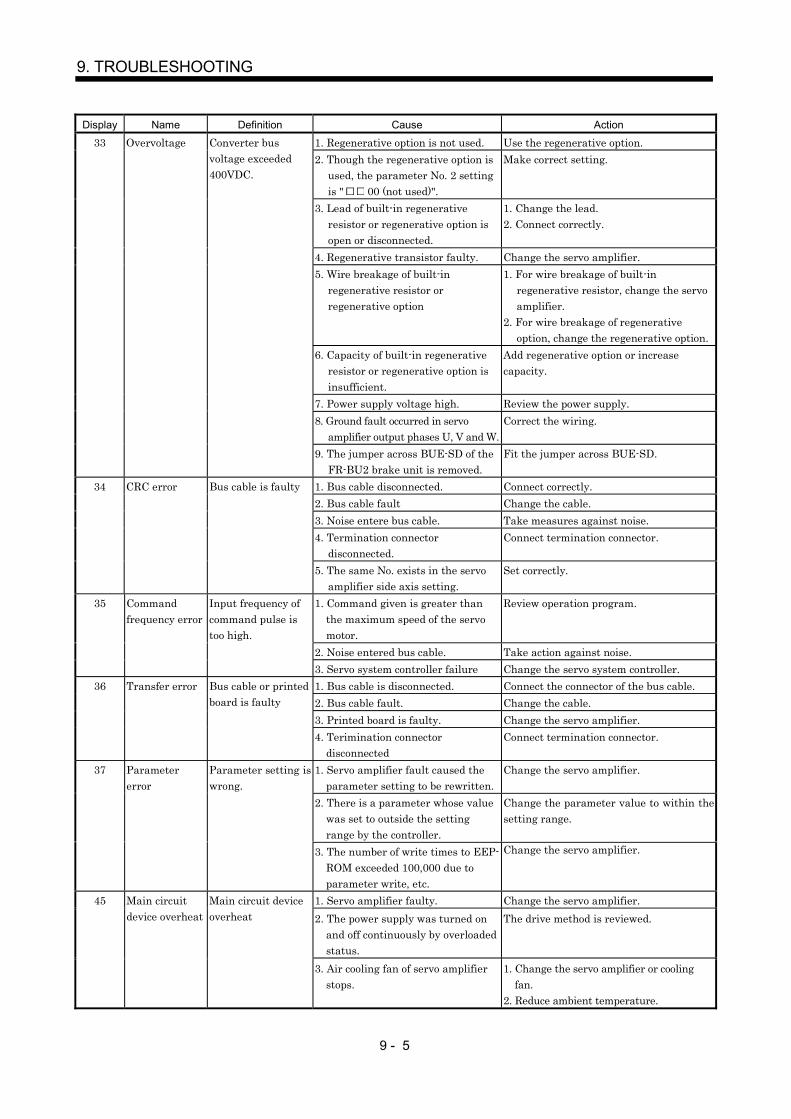
9 - 5
9. TROUBLESHOOTING
Display Name Definition Cause Action
1. Regenerative option is not used. Use the regenerative option.2. Though the regenerative option is
used, the parameter No. 2 settingis " 00 (not used)".
Make correct setting.
3. Lead of built-in regenerativeresistor or regenerative option isopen or disconnected.
1. Change the lead.2. Connect correctly.
4. Regenerative transistor faulty. Change the servo amplifier.5. Wire breakage of built-in
regenerative resistor orregenerative option
1. For wire breakage of built-inregenerative resistor, change the servoamplifier.
2. For wire breakage of regenerativeoption, change the regenerative option.
6. Capacity of built-in regenerativeresistor or regenerative option isinsufficient.
Add regenerative option or increasecapacity.
7. Power supply voltage high. Review the power supply.
33 Overvoltage Converter busvoltage exceeded400VDC.
8. Ground fault occurred in servoamplifier output phases U, V and W.
Correct the wiring.
9. The jumper across BUE-SD of theFR-BU2 brake unit is removed.
Fit the jumper across BUE-SD.
1. Bus cable disconnected. Connect correctly.2. Bus cable fault Change the cable.3. Noise entere bus cable. Take measures against noise.4. Termination connector
disconnected.Connect termination connector.
34 CRC error Bus cable is faulty
5. The same No. exists in the servoamplifier side axis setting.
Set correctly.
1. Command given is greater thanthe maximum speed of the servomotor.
Review operation program.
2. Noise entered bus cable. Take action against noise.
35 Commandfrequency error
Input frequency ofcommand pulse istoo high.
3. Servo system controller failure Change the servo system controller.1. Bus cable is disconnected. Connect the connector of the bus cable.2. Bus cable fault. Change the cable.3. Printed board is faulty. Change the servo amplifier.
36 Transfer error Bus cable or printedboard is faulty
4. Terimination connectordisconnected
Connect termination connector.
1. Servo amplifier fault caused theparameter setting to be rewritten.
Change the servo amplifier.
2. There is a parameter whose valuewas set to outside the settingrange by the controller.
Change the parameter value to within thesetting range.
37 Parametererror
Parameter setting iswrong.
3. The number of write times to EEP-ROM exceeded 100,000 due toparameter write, etc.
Change the servo amplifier.
1. Servo amplifier faulty. Change the servo amplifier.2. The power supply was turned on
and off continuously by overloadedstatus.
The drive method is reviewed.45 Main circuit
device overheatMain circuit deviceoverheat
3. Air cooling fan of servo amplifierstops.
1. Change the servo amplifier or coolingfan.
2. Reduce ambient temperature.
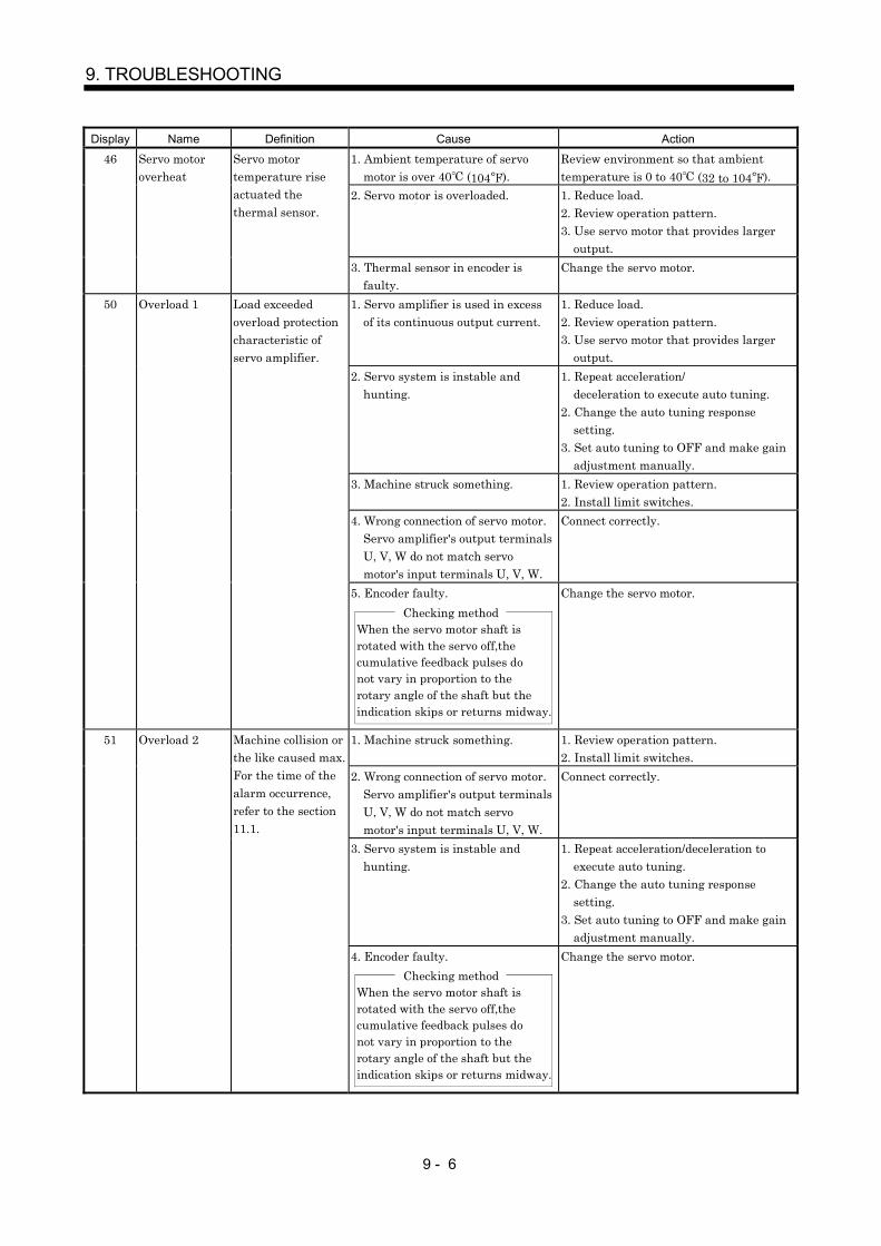
9 - 6
9. TROUBLESHOOTING
Display Name Definition Cause Action
1. Ambient temperature of servomotor is over 40 (104 ).
Review environment so that ambienttemperature is 0 to 40 (32 to 104 ).
2. Servo motor is overloaded. 1. Reduce load.2. Review operation pattern.3. Use servo motor that provides larger
output.
46 Servo motoroverheat
Servo motortemperature riseactuated thethermal sensor.
3. Thermal sensor in encoder isfaulty.
Change the servo motor.
1. Servo amplifier is used in excessof its continuous output current.
1. Reduce load.2. Review operation pattern.3. Use servo motor that provides larger
output.2. Servo system is instable and
hunting.1. Repeat acceleration/
deceleration to execute auto tuning.2. Change the auto tuning response
setting.3. Set auto tuning to OFF and make gain
adjustment manually.3. Machine struck something. 1. Review operation pattern.
2. Install limit switches.4. Wrong connection of servo motor.
Servo amplifier's output terminalsU, V, W do not match servomotor's input terminals U, V, W.
Connect correctly.
50 Overload 1 Load exceededoverload protectioncharacteristic ofservo amplifier.
5. Encoder faulty.Checking method
When the servo motor shaft isrotated with the servo off,the cumulative feedback pulses do not vary in proportion to therotary angle of the shaft but the indication skips or returns midway.
Change the servo motor.
1. Machine struck something. 1. Review operation pattern.2. Install limit switches.
2. Wrong connection of servo motor.Servo amplifier's output terminalsU, V, W do not match servomotor's input terminals U, V, W.
Connect correctly.
3. Servo system is instable andhunting.
1. Repeat acceleration/deceleration toexecute auto tuning.
2. Change the auto tuning responsesetting.
3. Set auto tuning to OFF and make gainadjustment manually.
51 Overload 2 Machine collision orthe like caused max.For the time of thealarm occurrence,refer to the section11.1.
4. Encoder faulty.Checking method
When the servo motor shaft isrotated with the servo off,the cumulative feedback pulses do not vary in proportion to therotary angle of the shaft but the indication skips or returns midway.
Change the servo motor.
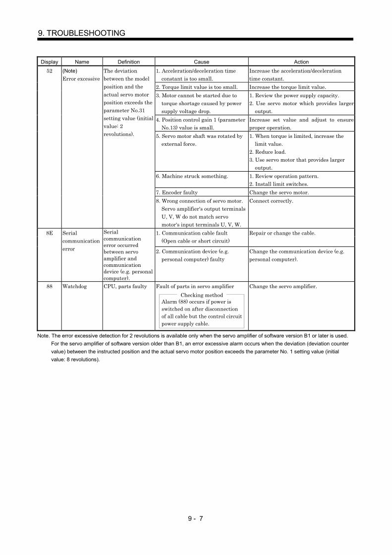
9 - 7
9. TROUBLESHOOTING
Display Name Definition Cause Action
1. Acceleration/deceleration timeconstant is too small.
Increase the acceleration/decelerationtime constant.
2. Torque limit value is too small. Increase the torque limit value.3. Motor cannot be started due to
torque shortage caused by powersupply voltage drop.
1. Review the power supply capacity.2. Use servo motor which provides larger
output.4. Position control gain 1 (parameter
No.13) value is small.Increase set value and adjust to ensureproper operation.
5. Servo motor shaft was rotated byexternal force.
1. When torque is limited, increase thelimit value.
2. Reduce load.3. Use servo motor that provides larger
output.6. Machine struck something. 1. Review operation pattern.
2. Install limit switches.7. Encoder faulty Change the servo motor.
52 (Note)Error excessive
The deviationbetween the modelposition and theactual servo motorposition exceeds theparameter No.31setting value (initialvalue: 2revolutions).
8. Wrong connection of servo motor.Servo amplifier's output terminalsU, V, W do not match servomotor's input terminals U, V, W.
Connect correctly.
1. Communication cable fault(Open cable or short circuit)
Repair or change the cable.8E Serialcommunicationerror
Serialcommunicationerror occurredbetween servoamplifier andcommunicationdevice (e.g. personalcomputer).
2. Communication device (e.g.personal computer) faulty
Change the communication device (e.g.personal computer).
88 Watchdog CPU, parts faulty Fault of parts in servo amplifierChecking method
Alarm (88) occurs if power is switched on after disconnection of all cable but the control circuit power supply cable.
Change the servo amplifier.
Note. The error excessive detection for 2 revolutions is available only when the servo amplifier of software version B1 or later is used.For the servo amplifier of software version older than B1, an error excessive alarm occurs when the deviation (deviation countervalue) between the instructed position and the actual servo motor position exceeds the parameter No. 1 setting value (initialvalue: 8 revolutions).

9 - 8
9. TROUBLESHOOTING
9.3 Remedies for warnings
POINTWhen any of the following alarms has occurred, do not resume operationby switching power of the servo amplifier OFF/ON repeatedly. The servoamplifier and servo motor may become faulty. If the power of the servoamplifier is switched OFF/ON during the alarms, allow more than 30minutes for cooling before resuming operation.
Excessive regenerative warning (E0)Overload warning 1 (E1)
If servo forced stop warning (E6), controller forced stop warning (E7) or SSCNET error warning (EE)occurs, the servo off status is established. If any other warning occurs, operation can be continued but analarm may take place or proper operation may not be performed. Eliminate the cause of the warningaccording to this section. Use the MR Configurator (servo configuration software) to refer to the cause ofwarning.Display Name Definition Cause Action
1. Battery cable is open. Repair cable or changed.92 Open batterycable warning
Absolute positiondetection system batteryvoltage is low.
2. Battery voltage supplied from the servoamplifier to the encoder fell to about3.2V or less.(Detected with the encoder)
Change the battery.
1. Droop pulses remaining are greaterthan the in-position range setting.
Remove the cause of droop pulseoccurrence.
2. Home position return was executedduring operation command.
96 Home positionsetting warning
Home position returncould not be made in theprecise position.
3. Creep speed high.
Reduce creep speed.
9F Battery warning Voltage of battery forabsolute positiondetection system reduced.
Battery voltage fell to 3.2V or less.(Detected with the servo amplifier)
Change the battery.
E0 Excessiveregenerativewarning
There is a possibility thatregenerative power mayexceed permissibleregenerative power ofbuilt-in regenerativeresistor or regenerativeoption.
Regenerative power increased to 85% ormore of permissible regenerative power ofbuilt-in regenerative resistor orregenerative option.
Checking methodCall the status display and checkregenerative load ratio.
1. Reduce frequency ofpositioning.
2. Change regenerative optionfor the one with largercapacity.
3. Reduce load.
E1 Overloadwarning
There is a possibility thatoverload alarm 1 or 2may occur.
Load increased to 85% or more of overloadalarm 1 or 2 occurrence level.
Cause, checking methodRefer to 50, 51.
Refer to 50, 51.
1. Noise entered the encoder. Take noise suppressionmeasures.
E3 Absolute positioncounter warning
Absolute position encoderpulses faulty.
2. Encoder faulty. Change the servo motor.E4 Parameter
warningParameter outsidesetting range.
Parameter value set from servo systemcontroller is outside setting range
Set it correctly.
E6 Servo forced stopwarning
EM1 is off. External forced stop was made valid.(EM1 turned off.)
Ensure safety and deactivateforced stop.
E7 Controller forcedstop warning
Forced stop signal was entered into theservo system controller.
Ensure safety and deactivateforced stop.
E9 Main circuit offwarning
Servo-on command wasissued with main circuitpower off.
Switch on main circuit power.
EE SSCNET errorwarning
The servo systemcontroller connected isnot SSCNET-compatible.

10 - 1
10. OUTLINE DIMENSION DRAWINGS
10. OUTLINE DIMENSION DRAWINGS
10.1 Servo amplifiers
(1) MR-J2S-10B to MR-J2S-60BMR-J2S-10B1 to MR-J2S-40B1
ENC
()
[Unit: mm]
6 ( 0.24) mounting hole
A 70 (2.76) 135 (5.32)
TE2
4(0.16)
B
168
(6.6
1)7
(0.2
8)
156
(6.1
4)6
(0.2
4)
6(0.24)
C N 1 A
OPEN
L1 L2 L3
U V W
MITSUBISHI
C N 1 B
C N 2 E N C
C N 3
20
([Unit: in])
Terminal layout(Terminal cover open)
PE terminal
(0.7
9)
6(0
.24)
(Note)
TE1
OPEN
MITSUBISHI
CN1A
CN2
CN1B
CN3
Rating plate
Variable dimensionsServo amplifier
A BMass
[kg]([lb])
MR-J2S-10B(1)MR-J2S-20B(1)
50 (1.97) 6 (0.24) 0.7 (1.54)
MR-J2S-40B(1)MR-J2S-60B
70 (2.76) 22 (0.87) 1.1 (2.43)
Note. This data applies to the 3-phase 200 to 230V and 1-phase 230V power supply models.
TE2
Front
D C P L21 L11
PE terminals
Terminal screw: M4Tightening torque: 1.2 [N m] (10.6 [lb in])
TE1
L1
U V W
Terminal screw: M4Tightening torque: 1.2 [N m] (10.6 [lb in])
U V W
Terminal screw: M4Tightening torque: 1.2 [N m] (10.6 [lb in])
L2 L3 L1 L2
Terminal signal layout
Mounting ScrewScrew Size:M5Tightening torque:3.24[N m](28.676 [lb in])
For 3-phase 200 to 230V and 1-phase 230V For 1-phase 100 to 120V
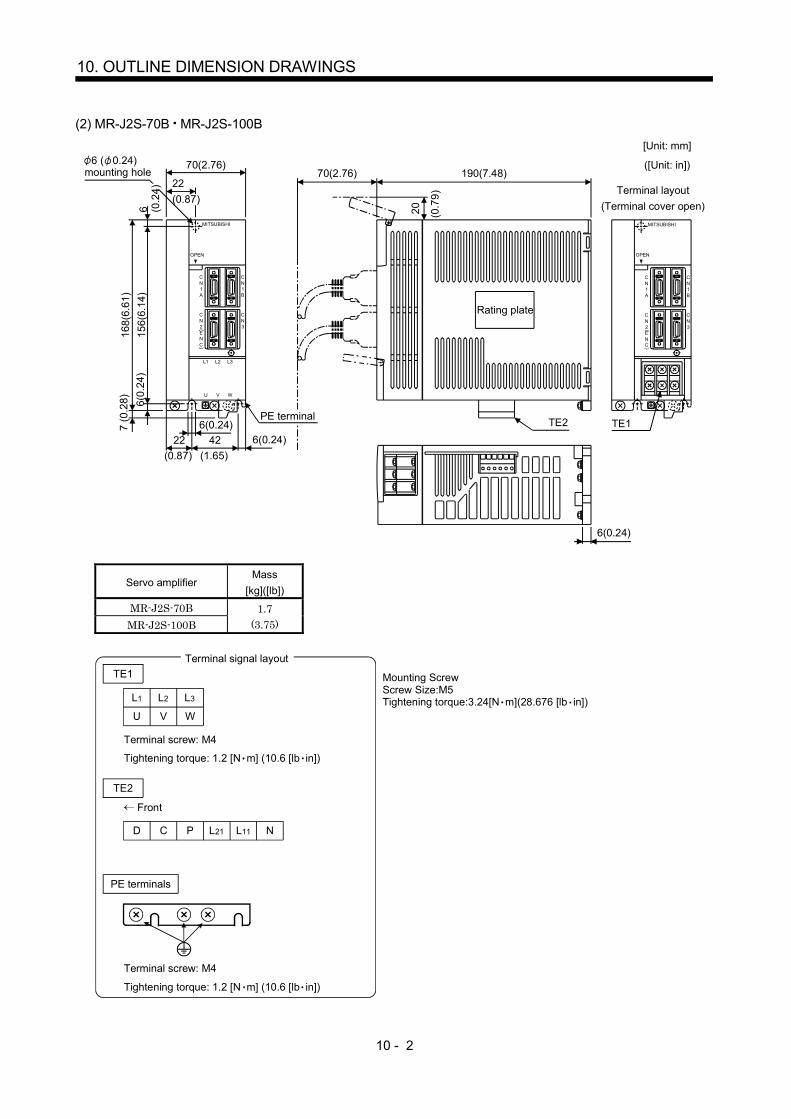
10 - 2
10. OUTLINE DIMENSION DRAWINGS
(2) MR-J2S-70B MR-J2S-100B
C N 1 A
OPEN
MITSUBISHI
C N 1 B
C N 2 E N C
C N 3
7 (0
.28)
C N 1 A
OPEN
L1 L2 L3
U V W
MITSUBISHI
C N 1 B
C N 2 E N C
C N 3
[Unit: mm]
([Unit: in])70(2.76)
70(2.76)190(7.48)
22
TE1TE2
6(0.24)
20 (0.7
9) Terminal layout (Terminal cover open)
6 ( 0.24) mounting hole
168(
6.61
)15
6(6.
14)
6(0.24)6(0.24)42
(1.65)22
(0.87)
6(0.
24)
PE terminal
6 (0.2
4)
(0.87)
Rating plate
Servo amplifierMass
[kg]([lb])
MR-J2S-70BMR-J2S-100B
1.7(3.75)
TE1
L1
U V W
Terminal screw: M4
Tightening torque: 1.2 [N m] (10.6 [lb in])
TE2
D C P N
PE terminals
Terminal screw: M4
Tightening torque: 1.2 [N m] (10.6 [lb in])
L2 L3
L21 L11
Front
Mounting ScrewScrew Size:M5Tightening torque:3.24[N m](28.676 [lb in])
Terminal signal layout
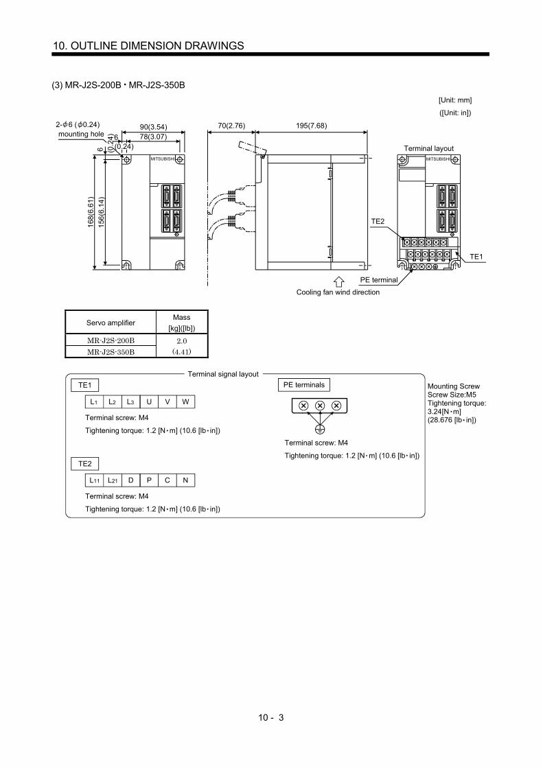
10 - 3
10. OUTLINE DIMENSION DRAWINGS
(3) MR-J2S-200B MR-J2S-350B
MITSUBISHI MITSUBISHI
70(2.76) 195(7.68)90(3.54)78(3.07)6
168(
6.61
)15
6(6.
14)
6
2- 6 ( 0.24)mounting hole
Terminal layout
TE1
[Unit: mm]
([Unit: in])
TE2
PE terminal
(0.24)(0.2
4)
Cooling fan wind direction
Servo amplifierMass
[kg]([lb])
MR-J2S-200BMR-J2S-350B
2.0(4.41)
TE1
L1 L2 L3 U V W
L11 L21 D P C N
Terminal screw: M4
Tightening torque: 1.2 [N m] (10.6 [lb in])
Terminal screw: M4
Tightening torque: 1.2 [N m] (10.6 [lb in])
TE2
PE terminals
Terminal screw: M4
Tightening torque: 1.2 [N m] (10.6 [lb in])
Mounting ScrewScrew Size:M5Tightening torque:3.24[N m](28.676 [lb in])
Terminal signal layout
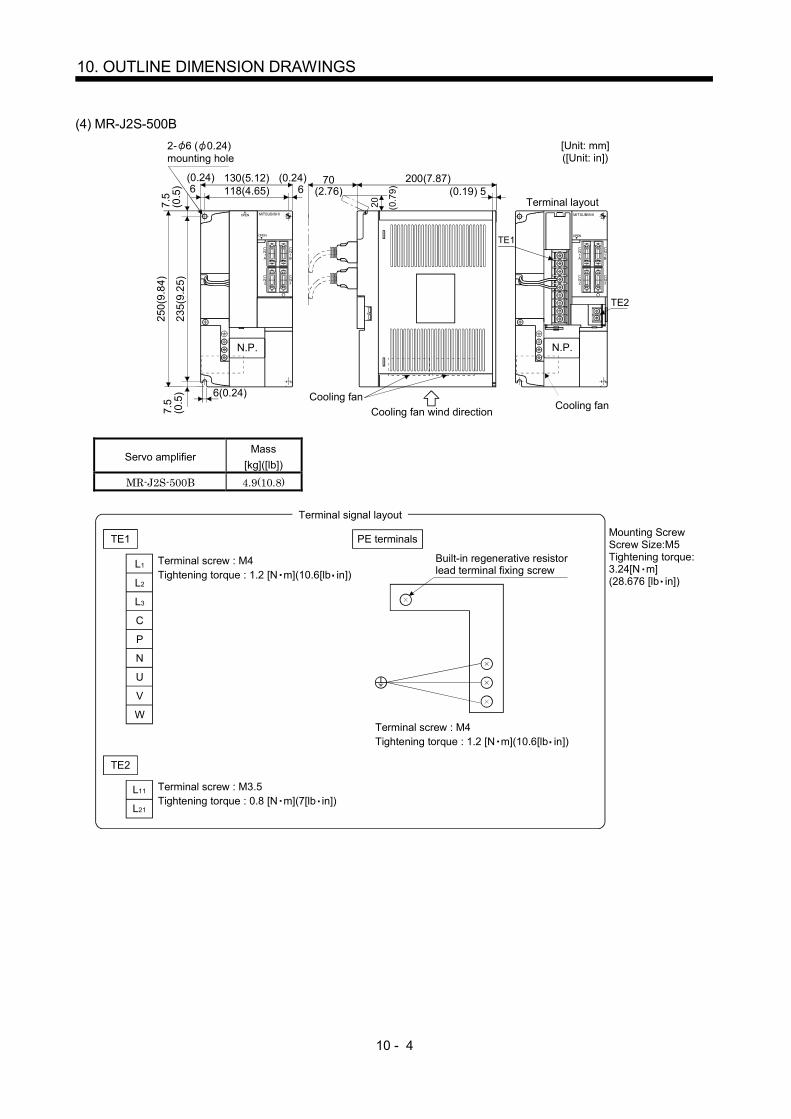
10 - 4
10. OUTLINE DIMENSION DRAWINGS
(4) MR-J2S-500B2- 6 ( 0.24)mounting hole
[Unit: mm]([Unit: in])
CN2
CN3
CN1A
CN1B
OPEN
OPEN
CN2
CN3
CN1A
CN1B
OPEN
TE1
TE2
130(5.12)118(4.65)
7.5
(0.5
)(0.24) 6
(0.24)
250(
9.84
)
235(
9.25
)7.
5(0
.5) 6(0.24)
N.P.
70(2.76)6
20 (0.7
9)
200(7.87)(0.19) 5
Terminal layout
N.P.
MITSUBISHI MITSUBISHI
Cooling fan wind direction Cooling fanCooling fan
Servo amplifierMass
[kg]([lb])
MR-J2S-500B 4.9(10.8)
TE1
TE2
L11
L21
N
L1
L2
L3
C
P
U
V
W
Terminal screw : M4Tightening torque : 1.2 [N m](10.6[lb in])
PE terminals
Terminal screw : M4Tightening torque : 1.2 [N m](10.6[lb in])
Terminal screw : M3.5Tightening torque : 0.8 [N m](7[lb in])
Mounting ScrewScrew Size:M5Tightening torque:3.24[N m](28.676 [lb in])
Terminal signal layout
Built-in regenerative resistorlead terminal fixing screw
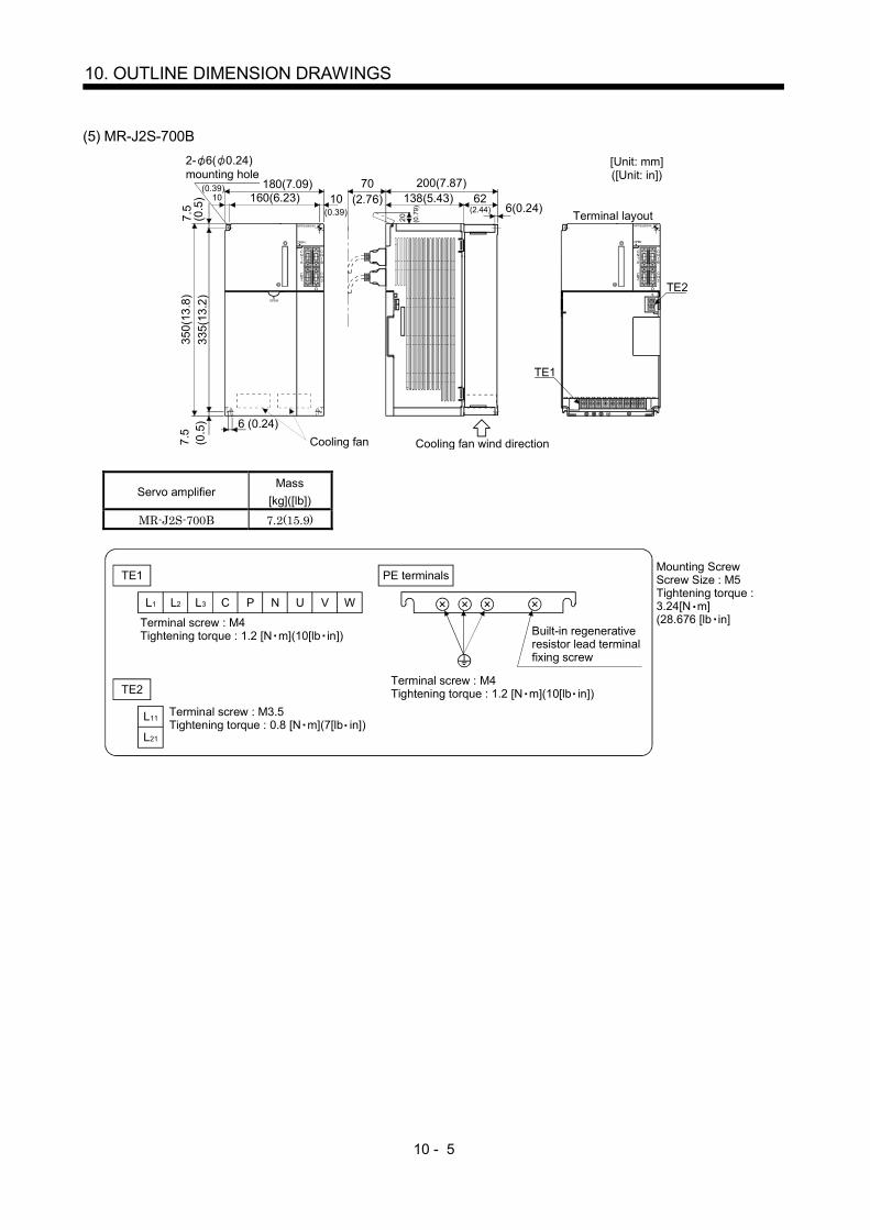
10 - 5
10. OUTLINE DIMENSION DRAWINGS
(5) MR-J2S-700B2- 6( 0.24)mounting hole
CN1B
CN1A
CN3
CN2
TE2
OPEN
CN1B
CN1A
CN3
CN2
TE1
7.5
(0.5
)(0.39)
10180(7.09)
160(6.23)(0.39)10
70(2.76)
200(7.87)138(5.43) 62
(2.44) 6(0.24) Terminal layout
[Unit: mm]([Unit: in])
20 (0.7
9)
350(
13.8
)33
5(13
.2)
7.5
(0.5
) 6 (0.24)
MITSUBISHI
OPEN
MITSUBISHI
OPEN
Cooling fan wind directionCooling fan
Servo amplifierMass
[kg]([lb])
MR-J2S-700B 7.2(15.9)
Terminal screw : M4Tightening torque : 1.2 [N m](10[lb in])
L1 L2 L3
TE1
TE2
NPC
L11
L21
WVU
Terminal screw : M3.5Tightening torque : 0.8 [N m](7[lb in])
PE terminals
Terminal screw : M4Tightening torque : 1.2 [N m](10[lb in])
Built-in regenerative resistor lead terminal fixing screw
Mounting Screw Screw Size : M5Tightening torque :3.24[N m](28.676 [lb in]

10 - 6
10. OUTLINE DIMENSION DRAWINGS
(6) MR-J2S-11KB 15KB
2- 12( 0.47)mounting hole
3.9(
0.15
)
75(2.95)12
(0.4
7)
CN3CN1ACN1B
CN4
MITSUBISHI
TE1
CON2
376(
14.8
)
400(
15.7
5)
1212(0.47)12(0.47)
(0.47)12 236(9.29)260(10.24)
CHARGECN2
TE2
(0.4
7)
[Unit: mm]([Unit: in])
260(
10.2
4)
Cooling fan
Cooling fan wind direction
Servo amplifierMass
[kg]([lb])
MR-J2S-11KB 15(33.1)MR-J2S-15KB 16(35.3)
TE2
L11 L21
Terminal screw : M4Tightening torque : 1.2[N m] (10.6[lb in])
L1 L2 L3
TE1
Terminal screw : M6Tightening torque : 3.0[N m] (26[lb in)]
WVU CPP1 N
PE terminal
Terminal screw : M6Tightening torque : 6.0[N m] (52[lb in)]
Mounting ScrewScrew Size:M10Tightening torque:26.5[N m](234.545[lb in])
Terminal signal layout

10 - 7
10. OUTLINE DIMENSION DRAWINGS
(7) MR-J2S-22KB
3.9(
0.15
)
Coolig fan wind direction75
(2.95)
[Unit: mm]([Unit: in])
CN3CN1ACN1B
CN4
MITSUBISHI
TE1
CON2
12(0
.47)
326(12.84)
376(
14.8
)
400(
15.7
5)
12
350(13.78)12(0.47)
12(0.47)(0.47)12
CHARGECN2TE2
2- 12( 0.47)mounting hole
(0.4
7)26
0(0.
24)
Cooling fan
Servo amplifierMass
[kg]([lb])
MR-J2S-22KB 20(44.1)
TE2
L11 L21
Terminal screw : M4Tightening torque : 1.2[N m] (10.6[lb in)]
L1 L2 L3
TE1
WVU CPP1 N
Terminal screw : M8Tightening torque : 6.0[N m] (52[lb in)]
PE terminal
Terminal screw : M8Tightening torque : 6.0[N m] (52[lb in)]
Mounting ScrewScrew Size:M10Tighting torque:26.5[N m](234.545[lb in])
Terminal signal layout

10 - 8
10. OUTLINE DIMENSION DRAWINGS
10.2 Connectors
(1) Servo amplifier side<3M>(a) Soldered type
12.0(0.47)
B
A
23.8
(0.9
4)39
.0(1
.54)
12.7(0.50)
14.0(0.55)
Logo, etc. are indicated here.
10.0
(0.3
9)
[Unit: mm] ([Unit: in])
Model Connector : 10120-3000PE 10126-3000PE Shell kit : 10320-52F0-008 10326-52F0-008
Variable dimensionsConnector Shell kit
A B
10120-3000PE 10320-52F0-008 22.0(0.87) 33.3(1.31)10126-3000PE 10326-52F0-008 25.8(1.02) 37.2(1.47)
(b) Threaded type
12.0(0.47)
33.3(1.31)
22.0(0.87)
23.8
(0.9
4)39
.0(1
.54)
12.7(0.50)
14.0(0.55)
Logo, etc. are indicated here.
10.0
(0.2
2)5.
7
27.4(1.08)
[Unit: mm] ([Unit: in])
(0.3
9)
Model Connector : 10120-3000PEShell kit : 10320-52A0-008 Note. This is not available as option and should be user-prepared.
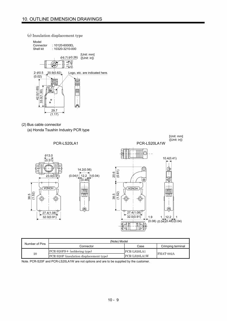
10 - 9
10. OUTLINE DIMENSION DRAWINGS
(c) Insulation displacement typeModel Connector : 10120-6000ELShell kit : 10320-3210-000
33.0
(1.3
0)42
.0(1
.65)
29.7(1.17)
20.9(0.82)
11.5
(0.4
5)
6.7
Logo, etc. are indicated here.2- 0.5(0.02)
[Unit: mm] ([Unit: in])( 0.26)
(2) Bus cable connector(a) Honda Tsushin Industry PCR type
23.0(0.91)
RS
1(0.04)(0.04)1 12.2(0.48)
14.2(0.56)
38.5
(1.5
2)
27.4(1.08)32.0(0.91)
HONDA
PCR-LS20LA1
38.5
(1.5
2)
27.4(1.08)32.0(0.91)
HONDA
RS
10.4(0.41)
1.9(0.08)
20.6
(0.8
1)
1 12.2(0.48)
PCR-LS20LA1W
13.0
(0.04) (0.04)1
[Unit: mm] ([Unit: in])
(0.51)
(Note) ModelNumber of Pins
Connector Case Crimping terminal
PCR-S20FS (soldering type)20
PCR-S20F (insulation displacement type)PCR-LS20LA1PCR-LS20LA1W
FHAT-002A
Note. PCR-S20F and PCR-LS20LA1W are not options and are to be supplied by the customer.

10 - 10
10. OUTLINE DIMENSION DRAWINGS
(b) Honda Tsushin Industry HDR type
Model HDRNumber of Pins
Connector Connector case (Note) Crimping terminal
14 HDR-E14MG1 HDR-E14LPA526 HDR-E26MG1 HDR-E26LPA5
Wire straightening tool : FHAT-0029Insulation displacement tool : FHPT-0004C
Note. Not available from us and to be supplied by the customer.
21 (0.83)
17 (0.67)5.6 ( 0.22)
2510
8.0
(0.3
9)(0
.98)
(0.3
2)Model Connector : HDR-E14MG1
Connector case : HDR-E14LPA5
25.8 (1.02)
21.8 (0.86)
2510
8.0
6 7 (0.24 0.28)
(0.3
9)(0
.98)
(0.3
2)
Model Connector : HDR-E26MG1Connector case : HDR-E26LPA5
[Unit: mm] ([Unit: in])
(3) Communication cable connector<Japan Aviation Electronics Industry>
CD
Fitting fixing screwGE(max. diameter of cable used)
F
A
B
[Unit: mm] ([Unit: in])
TypeA1
B1
C0.25
D1
EF
ReferenceG
DE-C1-J6-S6 34.5(1.36) 19(0.75) 24.99(0.98) 33(1.30) 6(0.24) 18(0.71) #4-40

11 - 1
11. CHARACTERISTICS
11. CHARACTERISTICS
11.1 Overload protection characteristics
An electronic thermal relay is built in the servo amplifier to protect the servo motor and servo amplifierfrom overloads. Overload 1 alarm (50) occurs if overload operation performed is above the electronicthermal relay protection curve shown in any of Figs 11.1, Overload 2 alarm (51) occurs if the maximumcurrent flew continuously for several seconds due to machine collision, etc. Use the equipment on the left-hand side area of the continuous or broken line in the graph.In a machine like the one for vertical lift application where unbalanced torque will be produced, it isrecommended to use the machine so that the unbalanced torque is 70% or less of the rated torque.
1000
100
10
1
0.1
0 50 150 200 250 300
(Note) Load ratio [%]
Ope
ratio
n tim
e[s]
100
During rotation
During servo lock
a. MR-J2S-10B to MR-J2S-100B
1000
100
10
1
0.1
0 50 150 200 250 300
(Note) Load ratio [%]
Ope
ratio
n tim
e[s]
100
During rotation
During servo lock
b. MR-J2S-200B to MR-J2S-350B
0 50 100 150 200 250 3001
10
100
1000
10000
(Note) Load ratio [%]
Ope
ratio
n tim
e[s] During rotation
During servo lock
c. MR-J2S-500B MR-J2S-700B
10000
1000
100
10
1
0 100 200 300
Ope
ratio
n tim
e[s]
(Note) Load ratio [%]
During rotation
During servo lock
d. MR-J2S-11KB to MR-J2S-22KB
Note. If operation that generates torque more than 100% of the rating is performed with an abnormally high frequency in a servo motorstop status (servo lock status) or in a 30r/min or less low-speed operation status, the servo amplifier may fail even when theelectronic thermal relay protection is not activated.
Fig 11.1 Electronic thermal relay protection characteristics
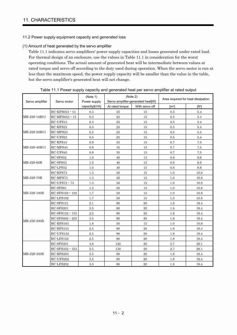
11 - 2
11. CHARACTERISTICS
11.2 Power supply equipment capacity and generated loss
(1) Amount of heat generated by the servo amplifierTable 11.1 indicates servo amplifiers' power supply capacities and losses generated under rated load.For thermal design of an enclosure, use the values in Table 11.1 in consideration for the worstoperating conditions. The actual amount of generated heat will be intermediate between values atrated torque and servo off according to the duty used during operation. When the servo motor is run atless than the maximum speed, the power supply capacity will be smaller than the value in the table,but the servo amplifier's generated heat will not change.
Table 11.1 Power supply capacity and generated heat per servo amplifier at rated output(Note 2)
Servo amplifier-generated heat[W]Area required for heat dissipation
Servo amplifier Servo motor(Note 1)
Power supplycapacity[kVA] At rated torque With servo off [m2] [ft2]
HC-KFS053 13 0.3 25 15 0.5 5.4HC-MFS053 13 0.3 25 15 0.5 5.4MR-J2S-10B(1)HC-UFS13 0.3 25 15 0.5 5.4HC-KFS23 0.5 25 15 0.5 5.4HC-MFS23 0.5 25 15 0.5 5.4MR-J2S-20B(1)HC-UFS23 0.5 25 15 0.5 5.4HC-KFS43 0.9 35 15 0.7 7.5HC-MFS43 0.9 35 15 0.7 7.5MR-J2S-40B(1)HC-UFS43 0.9 35 15 0.7 7.5HC-SFS52 1.0 40 15 0.8 8.6HC-SFS53 1.0 40 15 0.8 8.6MR-J2S-60BHC-LFS52 1.0 40 15 0.8 8.6HC-KFS73 1.3 50 15 1.0 10.8HC-MFS73 1.3 50 15 1.0 10.8MR-J2S-70BHC-UFS72 73 1.3 50 15 1.0 10.8HC-SFS81 1.5 50 15 1.0 10.8HC-SFS102 103 1.7 50 15 1.0 10.8MR-J2S-100BHC-LFS102 1.7 50 15 1.0 10.8HC-SFS121 2.1 90 20 1.8 19.4HC-SFS201 3.5 90 20 1.8 19.4HC-SFS152 153 2.5 90 20 1.8 19.4HC-SFS202 203 3.5 90 20 1.8 19.4HC-RFS103 1.8 50 15 1.0 10.8HC-RFS153 2.5 90 20 1.8 19.4HC-UFS152 2.5 90 20 1.8 19.4
MR-J2S-200B
HC-LFS152 2.5 90 20 1.8 19.4HC-SFS301 4.8 120 20 2.7 29.1HC-SFS352 353 5.5 130 20 2.7 29.1HC-RFS203 3.5 90 20 1.8 19.4HC-UFS202 3.5 90 20 1.8 19.4
MR-J2S-350B
HC-LFS202 3.5 90 20 1.8 19.4

11 - 3
11. CHARACTERISTICS
(Note 2)Servo amplifier-generated heat[W]
Area required for heat dissipationServo amplifier Servo motor
(Note 1)Power supplycapacity[kVA] At rated torque With servo off [m2] [ft2]
HC-SFS502 7.5 195 25 3.9 42.0HC-RFS353 5.5 135 25 2.7 29.1HC-RFS503 7.5 195 25 3.9 42.0HC-UFS352 5.5 195 25 3.9 42.0HC-UFS502 7.5 195 25 3.9 42.0HC-LFS302 4.5 120 25 2.4 25.8
MR-J2S-500B
HA-LFS502 7.5 195 25 3.9 42.0HC-SFS702 10.0 300 25 6.0 64.6
MR-J2S-700BHA-LFS702 10.6 300 25 6.0 64.6HA-LFS11K2 16.0 530 45 11 118.4HA-LFS801 12.0 390 45 7.8 83.9HA-LFS12K1 18.0 580 45 11.6 124.8
MR-J2S-11KB
HA-LFS11K1M 16.0 530 45 11.0 118.4HA-LFS15K2 22.0 640 45 13 139.0HA-LFS15K1 22.0 640 45 13 139.0MR-J2S-15KBHA-LFS15K1M 22.0 640 45 13 139.0HA-LFS22K2 33.0 850 55 17 183.0HA-LFS20K1 30.1 775 55 15.5 166.8HA-LFS25K1 37.6 970 55 19.4 208.8
MR-J2S-22KB
HA-LFS22K1M 33.0 850 55 17.0 193.0Note 1. Note that the power supply capacity will vary according to the power supply impedance. This value assumes that the power
factor improving reactor is not used.2. Heat generated during regeneration is not included in the servo amplifier-generated heat. To calculate heat generated by the
regenerative option, use Equation 12.1 refer to section 12.1.1.
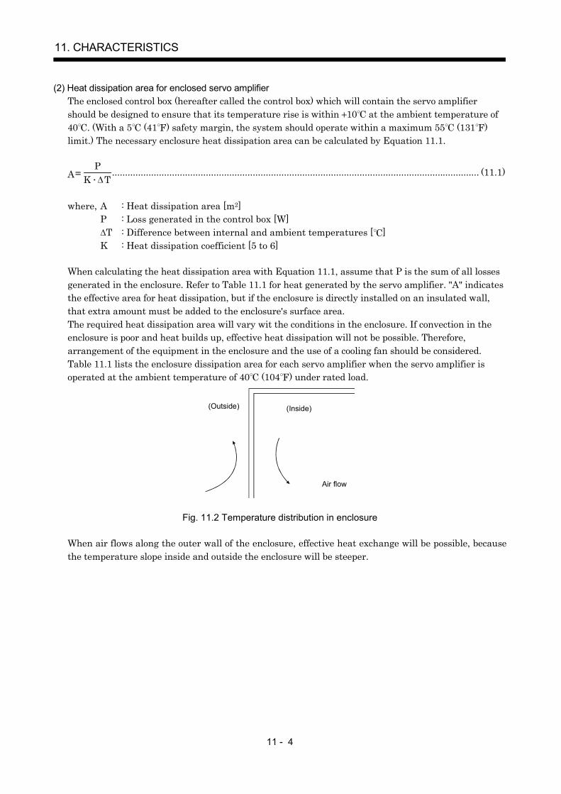
11 - 4
11. CHARACTERISTICS
(2) Heat dissipation area for enclosed servo amplifierThe enclosed control box (hereafter called the control box) which will contain the servo amplifiershould be designed to ensure that its temperature rise is within 10 at the ambient temperature of40 . (With a 5 (41 ) safety margin, the system should operate within a maximum 55 (131 )limit.) The necessary enclosure heat dissipation area can be calculated by Equation 11.1.
PA K T
............................................................................................................................................. (11.1)
where, A : Heat dissipation area [m2]P : Loss generated in the control box [W]
T : Difference between internal and ambient temperatures [ ]K : Heat dissipation coefficient [5 to 6]
When calculating the heat dissipation area with Equation 11.1, assume that P is the sum of all lossesgenerated in the enclosure. Refer to Table 11.1 for heat generated by the servo amplifier. "A" indicatesthe effective area for heat dissipation, but if the enclosure is directly installed on an insulated wall,that extra amount must be added to the enclosure's surface area.The required heat dissipation area will vary wit the conditions in the enclosure. If convection in theenclosure is poor and heat builds up, effective heat dissipation will not be possible. Therefore,arrangement of the equipment in the enclosure and the use of a cooling fan should be considered.Table 11.1 lists the enclosure dissipation area for each servo amplifier when the servo amplifier isoperated at the ambient temperature of 40 (104 ) under rated load.
(Outside) (Inside)
Air flow
Fig. 11.2 Temperature distribution in enclosure
When air flows along the outer wall of the enclosure, effective heat exchange will be possible, becausethe temperature slope inside and outside the enclosure will be steeper.
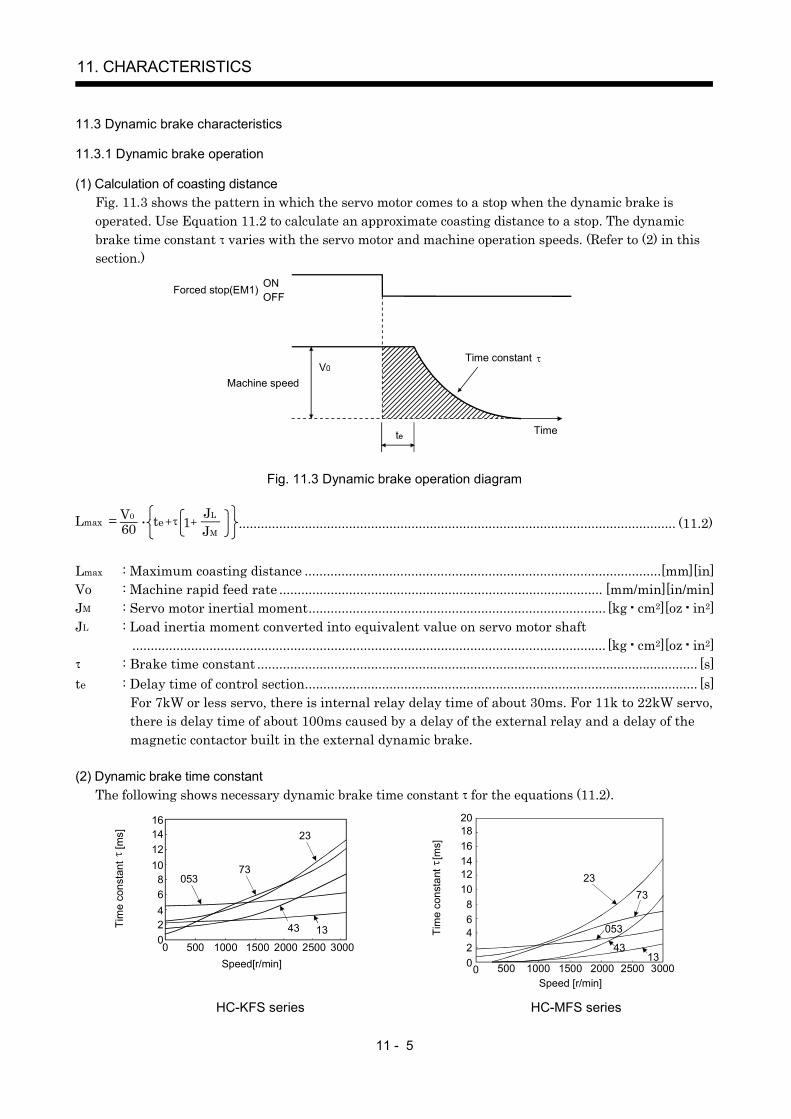
11 - 5
11. CHARACTERISTICS
11.3 Dynamic brake characteristics
11.3.1 Dynamic brake operation
(1) Calculation of coasting distanceFig. 11.3 shows the pattern in which the servo motor comes to a stop when the dynamic brake isoperated. Use Equation 11.2 to calculate an approximate coasting distance to a stop. The dynamicbrake time constant varies with the servo motor and machine operation speeds. (Refer to (2) in thissection.)
V0Time constant
Forced stop(EM1) OFFON
Machine speed
te Time
Fig. 11.3 Dynamic brake operation diagram
Lmax 60V0 JL
JMte 1 ....................................................................................................................... (11.2)
Lmax : Maximum coasting distance .................................................................................................[mm][in]Vo : Machine rapid feed rate ........................................................................................ [mm/min][in/min]JM : Servo motor inertial moment................................................................................. [kg cm2][oz in2]JL : Load inertia moment converted into equivalent value on servo motor shaft
................................................................................................................................. [kg cm2][oz in2]: Brake time constant ........................................................................................................................ [s]
te : Delay time of control section........................................................................................................... [s]For 7kW or less servo, there is internal relay delay time of about 30ms. For 11k to 22kW servo,there is delay time of about 100ms caused by a delay of the external relay and a delay of themagnetic contactor built in the external dynamic brake.
(2) Dynamic brake time constantThe following shows necessary dynamic brake time constant for the equations (11.2).
Speed[r/min]
0
1416
24
810
6
12
0 500 1000 1500 2000 2500 300013
73
23
43
053
Tim
e co
nsta
nt
[ms]
0Speed [r/min]
Tim
e co
nsta
nt
[ms]
20181614121086420 500 1000 1500 2000 2500 3000
2373
053
4313
HC-KFS series HC-MFS series
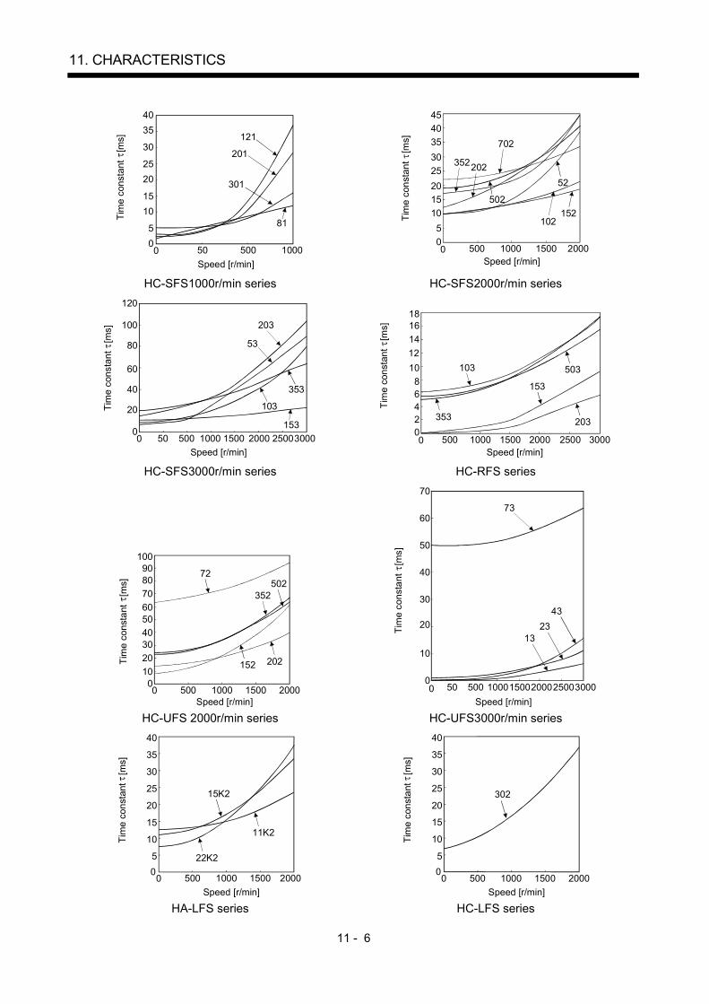
11 - 6
11. CHARACTERISTICS
Tim
e co
nsta
nt
[ms]
0Speed [r/min]
4035
30
2520
1510
50
50 500 1000
121
201
301
81 Tim
e co
nsta
nt
[ms]
Speed [r/min]0
352202
702
102152
454035302520151050
500 1000 1500 2000
502
52
HC-SFS1000r/min series HC-SFS2000r/min series
0Speed [r/min]
Tim
e co
nsta
nt
[ms]
120
100
80
60
40
20
050 500 1000 1500 25002000 3000
203
53
103
353
153
Speed [r/min]
Tim
e co
nsta
nt
[ms]
0
153
503103
353 203
1816141210
86420
500 1000 1500 2000 2500 3000
HC-SFS3000r/min series HC-RFS series
Tim
e co
nsta
nt
[ms]
Speed [r/min]
352
0
50272
202152
1009080706050403020100
500 1500 20001000 0Speed [r/min]
Tim
e co
nsta
nt
[ms]
70
60
50
40
30
20
10
050050 10001500200025003000
1323
43
73
HC-UFS 2000r/min series HC-UFS3000r/min series
00
40
35
30
25
20
15
10
5
11K2
22K2
15K2
Tim
e co
nsta
nt
[ms]
Speed [r/min]500 1000 1500 2000
0500 1000 1500 20000
40
35
30
25
20
15
10
5
302
Tim
e co
nsta
nt
[ms]
Speed [r/min]
HA-LFS series HC-LFS series

11 - 7
11. CHARACTERISTICS
11.3.2 The dynamic brake at the load inertia moment
Use the dynamic brake under the load inertia moment ratio indicated in the following table. If the loadinertia moment is higher than this value, the built-in dynamic brake may burn. If there is a possibilitythat the load inertia moment may exceed the value, contact Mitsubishi.
Servo amplifier Load inertia moment ratio [times]
MR-J2S-10B to MR-J2S-200BMR-J2S-10B1 to MR-J2S-40B1
30
MR-J2S-350B 16MR-J2S-500BMR-J2S-700B
15
(Note)MR-J2S-11KB to MR-J2S-22KB (Note) 30Note. Assumes that the external dynamic brake is used.
11.4 Encoder cable flexing life
The flexing life of the cables is shown below. This graph calculated values. Since they are not guaranteedvalues, provide a little allowance for these values.
1 107
5 107
1 108
5 106
1 106
5 105
1 105
5 104
1 104
5 103
1 103
a
b
Flex
ing
life
[tim
es]
4 7 10 20 40 70 100 200
Flexing radius [mm]
a : Long flexing-life encoder cable MR-JCCBL M-H MR-JHSCBL M-H MR-ENCBL M-H
b : Standard encoder cable MR-JCCBL M-L MR-JHSCBL M-L

11 - 8
11. CHARACTERISTICS
11.5 Inrush currents at power-on of main circuit and control circuit
The following table indicates the inrush currents (reference value) that will flow when the maximumpermissible voltage (253VAC) is applied at the power supply capacity of 2500kVA and the wiring length of10m.
Inrush Currents (A0-p)Servo amplifier
Main circuit power supply (L1, L2, L3) Control circuit power supply (L11, L21)
MR-J2S-10B 20B 30A (Attenuated to approx. 5A in 10ms)MR-J2S-40B 60B 30A (Attenuated to approx. 5A in 10ms)
MR-J2S-70B 100B 54A (Attenuated to approx. 12A in 10ms)
70 to 100A(Attenuated to approx. 0A in 0.5 to 1ms)
MR-J2S-200B 350B 120A (Attenuated to approx. 12A in 20ms)100 to 130A
(Attenuated to approx. 0A in 0.5 to 1ms)MR-J2S-500B 44A (Attenuated to approx. 20A in 20ms)MR-J2S-700B 88A (Attenuated to approx. 20A in 20ms)MR-J2S-11KBMR-J2S-15KBMR-J2S-22KB
235A (Attenuated to approx. 20A in 20ms)
30A(Attenuated to approx. 0A in several ms)
MR-J2S-10B1 20B1 59A (Attenuated to approx. 5A in 4ms)MR-J2S-40B1 72A (Attenuated to approx. 5A in 4ms)
100 to 130A(Attenuated to approx. 0A in 0.5 to 1ms)
Since large inrush currents flow in the power supplies, always use no-fuse breakers and magneticcontactors. (Refer to section 12.2.2.)When circuit protectors are used, it is recommended to use the inertia delay type that will not be trippedby an inrush current.

12 - 1
12. OPTIONS AND AUXILIARY EQUIPMENT
12. OPTIONS AND AUXILIARY EQUIPMENT
WARNING
Before connecting any option or peripheral equipment, turn off the power and waitfor 15 minutes or more until the charge lamp turns off. Then, confirm that thevoltage between P and N is safe with a voltage tester and others. Otherwise, anelectric shock may occur. In addition, always confirm from the front of the servoamplifier whether the charge lamp is off or not.
CAUTIONUse the specified auxiliary equipment and options. Unspecified ones may lead to afault or fire.
12.1 Options
12.1.1 Regenerative options
CAUTIONThe specified combinations of regenerative options and servo amplifiers may onlybe used. Otherwise, a fire may occur.
(1) Combination and regenerative power
The power values in the table are resistor-generated powers and not rated powers.
Regenerative power[W]
Servo amplifier Built-in regenerativeresistor
MR-RB032[40 ]
MR-RB12[40 ]
MR-RB32[40 ]
MR-RB30[13 ]
(Note)MR-RB50
[13 ]
MR-RB31[6.7 ]
(Note)MR-RB51
[6.7 ]
MR-J2S-10B(1) 30MR-J2S-20B(1) 10 30 100MR-J2S-40B(1) 10 30 100
MR-J2S-60B 10 30 100MR-J2S-70B 20 30 100 300MR-J2S-100B 20 30 100 300MR-J2S-200B 100 300 500MR-J2S-350B 100 300 500MR-J2S-500B 130 300 500MR-J2S-700B 170 300 500
Note. Always install a cooling fan.
(Note) Regenerative power[W]Servo amplifier External regenerative resistor
(Accessory)MR-RB65
[8 ]MR-RB66
[5 ]MR-RB67
[4 ]
MR-J2S-11KB 500 (800) 500 (800)MR-J2S-15KB 850 (1300) 850 (1300)MR-J2S-22KB 850 (1300) 850 (1300)
Note. Values in parentheses assume the installation of a cooling fan.

12 - 2
12. OPTIONS AND AUXILIARY EQUIPMENT
(2) Selection of the regenerative option(a) Simple selection method
In horizontal motion applications, select the regenerative option as described below.When the servo motor is run without load in the regenerative mode from the running speed to astop, the permissible duty is as indicated in section 5.1 of the separately available Servo MotorInstruction Manual.For the servo motor with a load, the permissible duty changes according to the inertia moment ofthe load and can be calculated by the following formula.
(m l)
ratedspeedrunning speed
[times/min]2
Permissible duty for servo motor with no load (value indication section 5.1 in Servo Motor Instruction Manual)Permissible duty
where m load inertia moment/servo motor inertia moment
From the permissible duty, find whether the regenerative option is required or not.Permissible duty number of positioning times [times/min]Select the regenerative option out of the combinations in (1) in this section.
(b) To make selection according to regenerative energyUse the following method when regeneration occurs continuously in vertical motion applications orwhen it is desired to make an in-depth selection of the regenerative option.
a. Regenerative energy calculationUse the following table to calculate the regenerative energy.
M
Friction torque
Unb
alan
ce to
rque
TF
TU
Ser
vo m
otor
spe
edG
ener
ated
torq
ue
Time
UpNotf(1 cycle)
Down
( )
( )
(Driving)
(Regenerative)
Tpsd2
t2 t3 t4t1Tpsa2Tpsd1Tpsa1
1)
2)
3)
4)5)
6)
7)
8)
Formulas for calculating torque and energy in operation
Regenerative power Torque applied to servo motor [N m] Energy [J]
1) T1(JL JM)
9.55 104No 1
Tpsa1TU TF E1 2
0.1047 No T1 Tpsa1
2) T2 TU TF E2 0.1047 No T2 t1
3) T39.55 104
1Tpsa1
TU TF(JL JM) No E3 2
0.1047 No T3 Tpsd1
4), 8) T4 TU E4 0 (No regeneration)
5) T5(JL JM)
9.55 104No 1
Tpsa2TU TF E5 2
0.1047 No T5 Tpsa2
6) T6 TU TF E6 0.1047 No T6 t3
7) T79.55 104
1Tpsa2
TU TF(JL JM) No E7 2
0.1047 No T7 Tpsd2
From the calculation results in 1) to 8), find the absolute value (Es) of the sum total of negativeenergies.

12 - 3
12. OPTIONS AND AUXILIARY EQUIPMENT
b. Losses of servo motor and servo amplifier in regenerative modeThe following table lists the efficiencies and other data of the servo motor and servo amplifier inthe regenerative mode.
Servo amplifier Inverse efficiency[%] Capacitor charging[J]MR-J2S-10B 55 9MR-J2S-10B1 55 4MR-J2S-20B 70 9MR-J2S-20B1 70 4MR-J2S-40B 85 11MR-J2S-40A1 85 12MR-J2S-60B 85 11MR-J2S-70B 80 18MR-J2S-100B 80 18MR-J2S-200B 85 40MR-J2S-350B 85 40MR-J2S-500B 90 45MR-J2S-700B 90 70MR-J2S-11KB 90 120MR-J2S-15KB 90 170MR-J2S-22KB 90 250
Inverse efficiency ( ) :Efficiency including some efficiencies of the servo motor and servoamplifier when rated (regenerative) torque is generated at rated speed.Since the efficiency varies with the speed and torque, allow for about 10%.
Capacitor charging (Ec) :Energy charged into the electrolytic capacitor in the servo amplifier.
Subtract the capacitor charging from the result of multiplying the sum total of regenerative energies bythe inverse efficiency to calculate the energy consumed by the regenerative option.
ER [J] Es EcCalculate the power consumption of the regenerative option on the basis of single-cycle operation period tf[s] to select the necessary regenerative option.
PR [W] ER/tf
(3) Parameter settingSet parameter No.2 according to the option to be used.The MR-RB65, 66 and 67 are regenerative options that have encased the GRZG400-2 , GRZG400-1and GRZG400-0.8 , respectively. When using any of these regenerative options, make the sameparameter setting as when using the GRZG400-2 , GRZG400-1 or GRZG400-0.8 (suppliedregenerative resistors or regenerative option is used with 11kW or more servo amplifier).
Selection of regenerative00: Regenerative option is not used with 7kW or less servo amplifier (The built-in regenerative resistor is used. However, the MR-J2S-10B does not have a built-in regenerative resistor and therefore cannot use it.) Supplied regenerative resistors or regenerative option is used with 11k to 22kW servo amplifier01: FR-RC, FR-BU2, FR-CV05: MR-RB3208: MR-RB3009: MR-RB50(Cooling fan is required)0B: MR-RB310C: MR-RB51(Cooling fan is required)0E: When regenerative resistors or regenerative option supplied to 11k to 22kW are cooled by cooling fans to increase capability10: MR-RB03211: MR-RB12
Parameter No.2
0 0
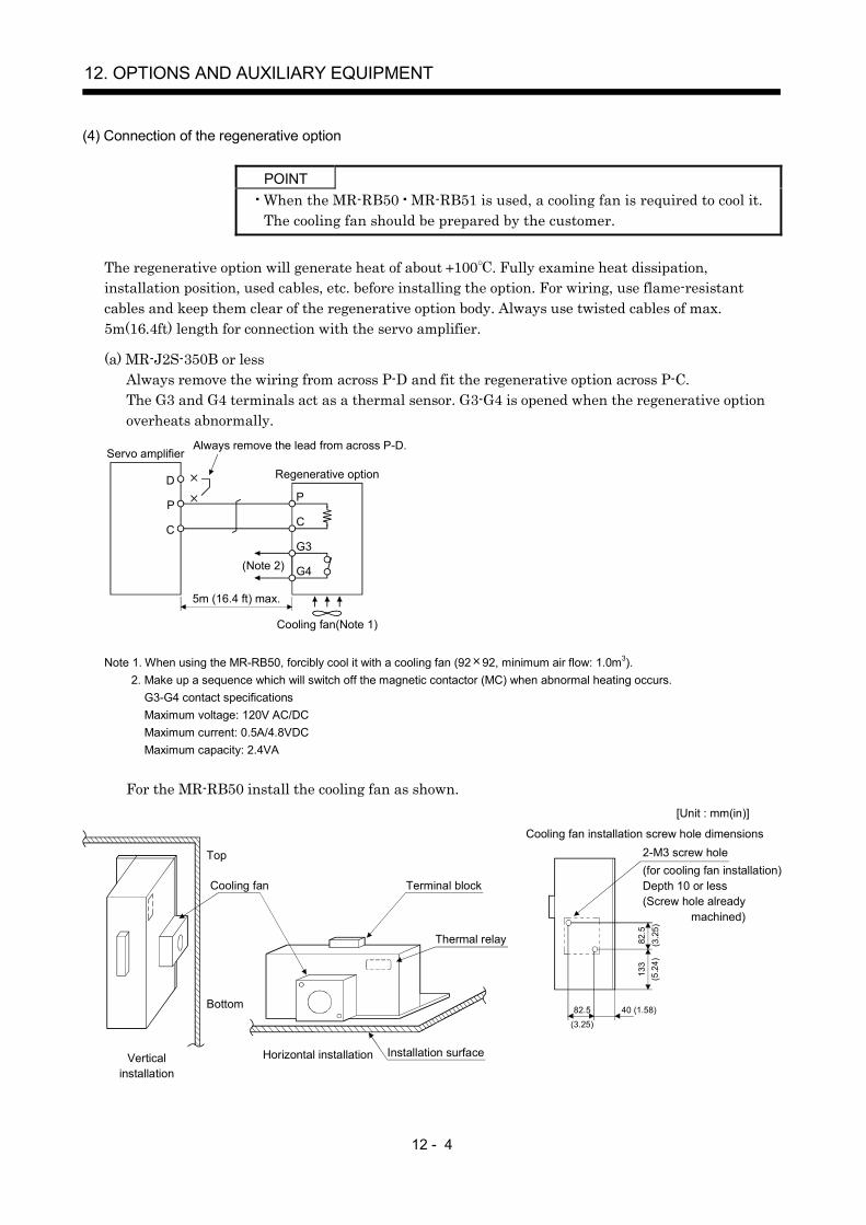
12 - 4
12. OPTIONS AND AUXILIARY EQUIPMENT
(4) Connection of the regenerative option
POINTWhen the MR-RB50 MR-RB51 is used, a cooling fan is required to cool it.The cooling fan should be prepared by the customer.
The regenerative option will generate heat of about 100 . Fully examine heat dissipation,installation position, used cables, etc. before installing the option. For wiring, use flame-resistantcables and keep them clear of the regenerative option body. Always use twisted cables of max.5m(16.4ft) length for connection with the servo amplifier.
(a) MR-J2S-350B or lessAlways remove the wiring from across P-D and fit the regenerative option across P-C.The G3 and G4 terminals act as a thermal sensor. G3-G4 is opened when the regenerative optionoverheats abnormally.
Servo amplifier
Regenerative option
Always remove the lead from across P-D.
D
P
C
G4
G3(Note 2)
5m (16.4 ft) max.
Cooling fan(Note 1)
C
P
Note 1. When using the MR-RB50, forcibly cool it with a cooling fan (92 92, minimum air flow: 1.0m3).2. Make up a sequence which will switch off the magnetic contactor (MC) when abnormal heating occurs. G3-G4 contact specifications Maximum voltage: 120V AC/DC Maximum current: 0.5A/4.8VDC Maximum capacity: 2.4VA
For the MR-RB50 install the cooling fan as shown.
82.5 40 (1.58)
82.5
133
Cooling fan installation screw hole dimensions2-M3 screw hole(for cooling fan installation)Depth 10 or less(Screw hole already
machined)
Cooling fan Terminal block
Thermal relay
Installation surfaceHorizontal installationVerticalinstallation
Top
Bottom
(3.2
5)(5
.24)
(3.25)
[Unit : mm(in)]
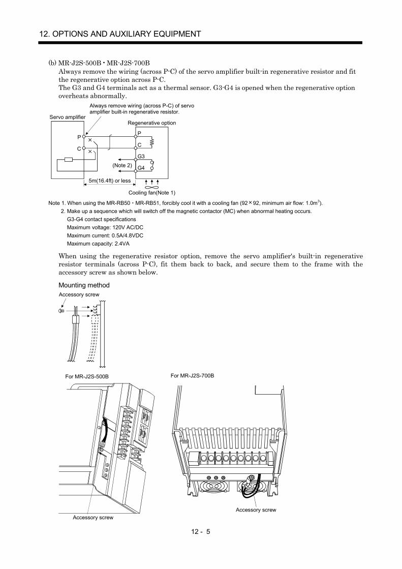
12 - 5
12. OPTIONS AND AUXILIARY EQUIPMENT
(b) MR-J2S-500B MR-J2S-700BAlways remove the wiring (across P-C) of the servo amplifier built-in regenerative resistor and fitthe regenerative option across P-C.The G3 and G4 terminals act as a thermal sensor. G3-G4 is opened when the regenerative optionoverheats abnormally.
Servo amplifierRegenerative option
Always remove wiring (across P-C) of servoamplifier built-in regenerative resistor.
P
C
G4
G3(Note 2)
5m(16.4ft) or less
Cooling fan(Note 1)
C
P
Note 1. When using the MR-RB50 MR-RB51, forcibly cool it with a cooling fan (92 92, minimum air flow: 1.0m3).2. Make up a sequence which will switch off the magnetic contactor (MC) when abnormal heating occurs. G3-G4 contact specifications Maximum voltage: 120V AC/DC Maximum current: 0.5A/4.8VDC Maximum capacity: 2.4VA
When using the regenerative resistor option, remove the servo amplifier's built-in regenerativeresistor terminals (across P-C), fit them back to back, and secure them to the frame with theaccessory screw as shown below.
Mounting methodAccessory screw
For MR-J2S-500B For MR-J2S-700B
Accessory screwAccessory screw
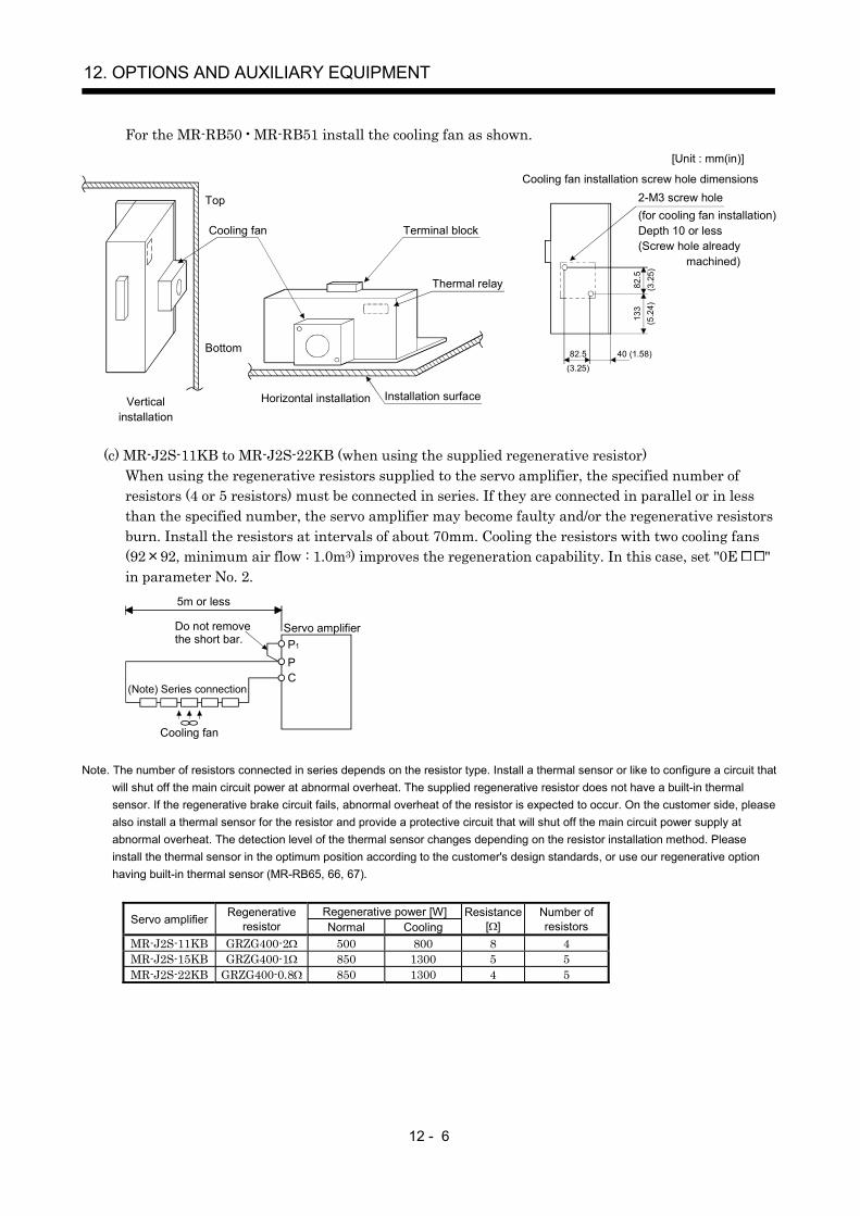
12 - 6
12. OPTIONS AND AUXILIARY EQUIPMENT
For the MR-RB50 MR-RB51 install the cooling fan as shown.
82.5 40 (1.58)
82.5
133
Cooling fan installation screw hole dimensions2-M3 screw hole(for cooling fan installation)Depth 10 or less(Screw hole already
machined)
Cooling fan Terminal block
Thermal relay
Installation surfaceHorizontal installationVerticalinstallation
Top
Bottom
(3.2
5)(5
.24)
(3.25)
[Unit : mm(in)]
(c) MR-J2S-11KB to MR-J2S-22KB (when using the supplied regenerative resistor)When using the regenerative resistors supplied to the servo amplifier, the specified number ofresistors (4 or 5 resistors) must be connected in series. If they are connected in parallel or in lessthan the specified number, the servo amplifier may become faulty and/or the regenerative resistorsburn. Install the resistors at intervals of about 70mm. Cooling the resistors with two cooling fans(92 92, minimum air flow : 1.0m3) improves the regeneration capability. In this case, set "0E "in parameter No. 2.
PC
Cooling fan
5m or less
Do not removethe short bar.
Servo amplifierP1
(Note) Series connection
Note. The number of resistors connected in series depends on the resistor type. Install a thermal sensor or like to configure a circuit thatwill shut off the main circuit power at abnormal overheat. The supplied regenerative resistor does not have a built-in thermalsensor. If the regenerative brake circuit fails, abnormal overheat of the resistor is expected to occur. On the customer side, pleasealso install a thermal sensor for the resistor and provide a protective circuit that will shut off the main circuit power supply atabnormal overheat. The detection level of the thermal sensor changes depending on the resistor installation method. Pleaseinstall the thermal sensor in the optimum position according to the customer's design standards, or use our regenerative optionhaving built-in thermal sensor (MR-RB65, 66, 67).
Regenerative power [W]Servo amplifier Regenerativeresistor Normal Cooling
Resistance[ ]
Number ofresistors
MR-J2S-11KB GRZG400-2 500 800 8 4MR-J2S-15KB GRZG400-1 850 1300 5 5MR-J2S-22KB GRZG400-0.8 850 1300 4 5

12 - 7
12. OPTIONS AND AUXILIARY EQUIPMENT
(d) MR-J2S-11KB-PX to MR-J2S-22KB-PX (when using the regenerative option)The MR-J2S-11KB-PX to MR-J2S-22KB-PX servo amplifiers are not supplied with regenerativeresistors. When using any of these servo amplifiers, always use the MR-RB65, 66 or 67regenerative option.The MR-RB65, 66 and 67 are regenerative options that have encased the GRZG400-2Ω, GRZG400-1Ω and GRZG400-0.8Ω, respectively. When using any of these regenerative options, make thesame parameter setting as when using the GRZG400-2Ω, GRZG400-1Ω or GRZG400-0.8Ω(supplied regenerative resistors or regenerative option is used with 11kW or more servo amplifier).Cooling the regenerative option with cooling fans improves regenerative capability.The G3 and G4 terminals are for the thermal sensor. G3-G4 is opened when the regenerativeoption overheats abnormally.
G3
G4
C
PCP
P1Regenerative optionDo not remove
the short bar.
Configure up a circuit whichshuts off main circuit powerwhen thermal sensor operates.
Servo amplifier
(Note)
Note. Specifications of contact across G3-G4Maximum voltage :120V AC/DCMaximum current :0.5A/4.8VDCMaximum capacity : 2.4VA
Regenerative power [W]Servo amplifier Regenerative
option modelResistance
[ ] Withoutcooling fans
Withcooling fans
MR-J2S-11KB-PX MR-RB65 8 500 800MR-J2S-15KB-PX MR-RB66 5 850 1300MR-J2S-22KB-PX MR-RB67 4 850 1300
When using cooling fans, install them using the mounting holes provided in the bottom of theregenerative option. In this case, set "0E " in parameter No. 2.
Top
Bottom
TE1
G4 G3 C PTE
2 cooling fans(92 92, minimum air flow: 1.0m3)
MR-RB65 66 67
Mounting screw4-M3(0.118)
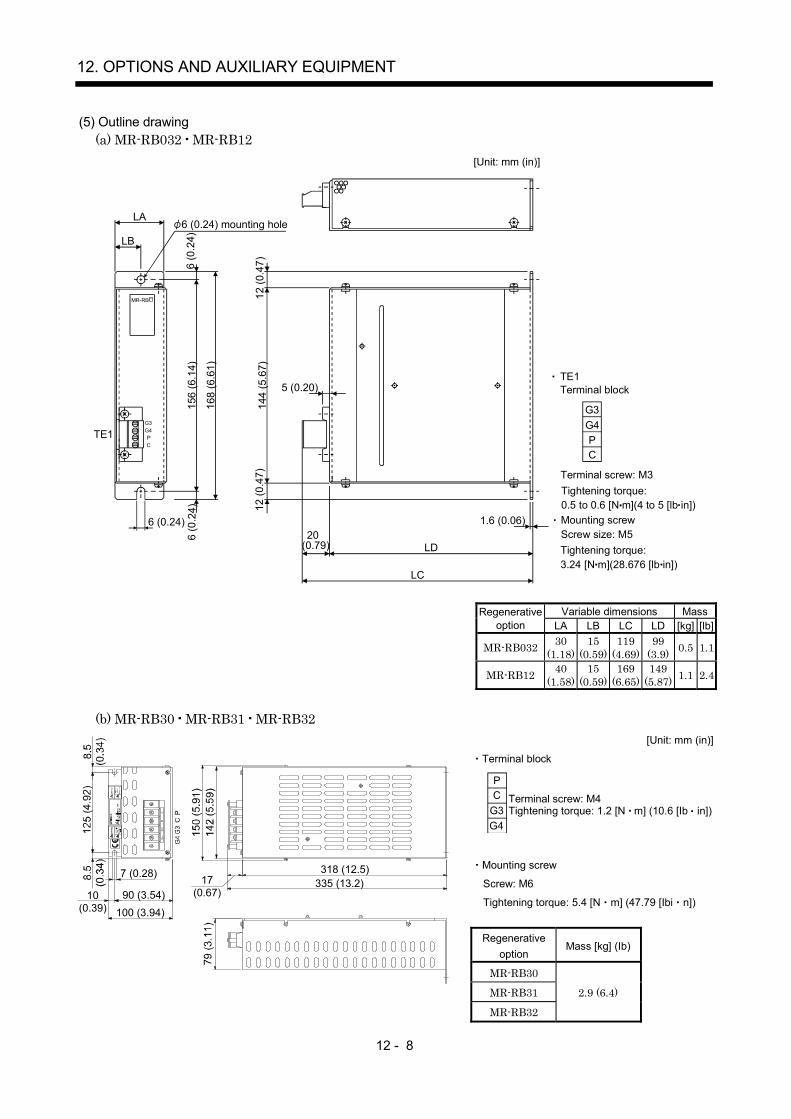
12 - 8
12. OPTIONS AND AUXILIARY EQUIPMENT
(5) Outline drawing(a) MR-RB032 MR-RB12
LA
5 (0.20)
LB
TE1
6 (0.24)
6 (0
. 24)
156
(6.1
4)
1 68
(6.6
1)
144
(5.6
7)12
(0.4
7)
6 (0
.24)
12 (0
.47)
20 (0.79) LD
1.6 (0.06)
LC
G3 G4 P C
[Unit: mm (in)]
6 (0.24) mounting hole
MR-RB
TE1Terminal block
G4G3
CP
Terminal screw: M3
Tightening torque: 3.24 [N m](28.676 [lb in])
Mounting screwScrew size: M5
Tightening torque: 0.5 to 0.6 [N m](4 to 5 [lb in])
Variable dimensions MassRegenerativeoption LA LB LC LD [kg] [lb]
MR-RB032 30(1.18)
15(0.59)
119(4.69)
99(3.9) 0.5 1.1
MR-RB12 40(1.58)
15(0.59)
169(6.65)
149(5.87) 1.1 2.4
(b) MR-RB30 MR-RB31 MR-RB32[Unit: mm (in)]
Terminal block
G4G3CP
Terminal screw: M4Tightening torque: 1.2 [N m] (10.6 [Ib in])
Mounting screw
Screw: M6
Tightening torque: 5.4 [N m] (47.79 [Ibi n])
Regenerativeoption
Mass [kg] (Ib)
MR-RB30
MR-RB31 2.9 (6.4)
7 (0.28)
10(0.39)
90 (3.54)100 (3.94)
17(0.67)
318 (12.5)335 (13.2)
MR-RB32
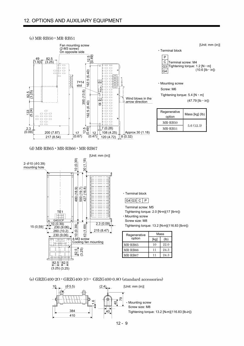
12 - 9
12. OPTIONS AND AUXILIARY EQUIPMENT
(c) MR-RB50 MR-RB51[Unit: mm (in)]
Terminal block
G4G3CP
Terminal screw: M4Tightening torque: 1.2 [N m]
(10.6 [Ib in])
Mounting screw
Screw: M6
Tightening torque: 5.4 [N m]
(47.79 [Ib in])
Regenerativeoption
Mass [kg] (Ib)
MR-RB50
MR-RB515.6 (12.3)
2.3(0.09)
49(1.93)
82.5(3.25)
200 (7.87)217 (8.54)
17(0.67) 8 (0.32)120 (4.72)
108 (4.25) 12(0.47)
7 (0.28)Approx.30 (1.18)
7 14slot
Fan mounting screw(2-M3 screw)On opposite side
Wind blows in thearrow direction
(d) MR-RB65 MR-RB66 MR-RB67
G4 G3 C P
Terminal block
Terminal screw: M5Tightening torque: 2.0 [N m](17 [lb in])
Tightening torque: 13.2 [N m](116.83 [lb in])
Mounting screwScrew size: M8
10 (0
.39)
43 (1
.69)
480
(18.
9)50
0 (1
9.7)
427
(16.
8)
10 (0
.39)
30 (1
.18)
215 (8.47)
2.3 (0.09)10 (0.39)230 (9.06)260 (10.2)230 (9.06)
TE1
G4G3 CP
[Unit: mm (in)]
15 (0.59)
82.5 82.5
82.5
(3.2
5)
(3.25)(3.25)
2- 10 ( 0.39)mounting hole
4-M3 screwCooling fan mounting
Regenerative option
Mass
MR-RB65MR-RB66MR-RB67
[kg] (lb)10 22.011 24.311 24.3
(e) GRZG400-2 GRZG400-1 GRZG400-0.8 (standard accessories)
1.6
40410384
10 ( 5.5) (2.4)
40
79
[Unit: mm (in)]
Tightening torque: 13.2 [N m](116.83 [lb in])
Mounting screwScrew size: M8
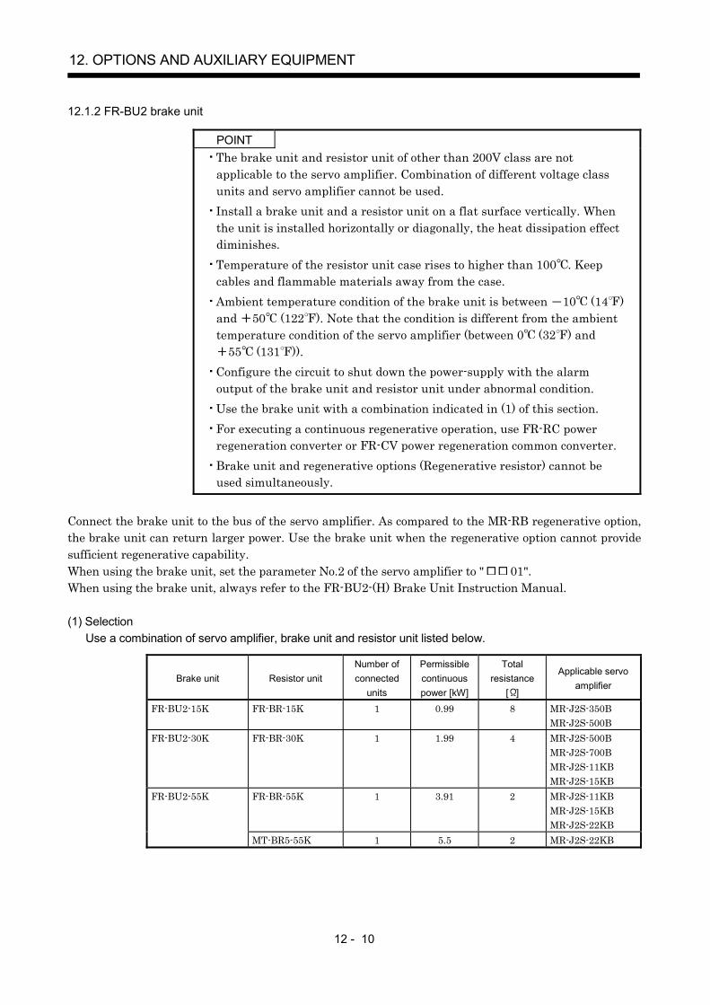
12 - 10
12. OPTIONS AND AUXILIARY EQUIPMENT
12.1.2 FR-BU2 brake unit
POINTThe brake unit and resistor unit of other than 200V class are notapplicable to the servo amplifier. Combination of different voltage classunits and servo amplifier cannot be used.Install a brake unit and a resistor unit on a flat surface vertically. Whenthe unit is installed horizontally or diagonally, the heat dissipation effectdiminishes.Temperature of the resistor unit case rises to higher than 100 . Keepcables and flammable materials away from the case.Ambient temperature condition of the brake unit is between 10 (14 )and 50 (122 ). Note that the condition is different from the ambienttemperature condition of the servo amplifier (between 0 (32 ) and
55 (131 )).Configure the circuit to shut down the power-supply with the alarmoutput of the brake unit and resistor unit under abnormal condition.Use the brake unit with a combination indicated in (1) of this section.For executing a continuous regenerative operation, use FR-RC powerregeneration converter or FR-CV power regeneration common converter.Brake unit and regenerative options (Regenerative resistor) cannot beused simultaneously.
Connect the brake unit to the bus of the servo amplifier. As compared to the MR-RB regenerative option,the brake unit can return larger power. Use the brake unit when the regenerative option cannot providesufficient regenerative capability.When using the brake unit, set the parameter No.2 of the servo amplifier to " 01".When using the brake unit, always refer to the FR-BU2-(H) Brake Unit Instruction Manual.
(1) SelectionUse a combination of servo amplifier, brake unit and resistor unit listed below.
Brake unit Resistor unitNumber ofconnected
units
Permissiblecontinuouspower [kW]
Totalresistance
[ ]
Applicable servoamplifier
FR-BU2-15K FR-BR-15K 1 0.99 8 MR-J2S-350BMR-J2S-500B
FR-BU2-30K FR-BR-30K 1 1.99 4 MR-J2S-500BMR-J2S-700BMR-J2S-11KBMR-J2S-15KB
FR-BU2-55K FR-BR-55K 1 3.91 2 MR-J2S-11KBMR-J2S-15KBMR-J2S-22KB
MT-BR5-55K 1 5.5 2 MR-J2S-22KB

12 - 11
12. OPTIONS AND AUXILIARY EQUIPMENT
(2) Brake unit parameter settingNormally, when using the FR-BU2, changing parameters is not necessary. Whether a parameter canbe changed or not is listed below.
Parameter
No. Name
Changepossible/
impossibleRemarks
0 Brake mode switchover Impossible Do not change the parameter.1 Monitor display data selection Possible Refer to the FR-BU2-(H) Brake Unit
Instruction Manual.2 Input terminal function selection 13 Input terminal function selection 2
77 Parameter write selection78 Cumulative energization time
carrying-over timesCLr Parameter clearECL Alarm history clearC1 For manufacturer setting
Impossible Do not change the parameter.
(3) Connection example
POINTConnecting PR terminal of the brake unit to P terminal of the servoamplifier results in brake unit malfunction. Always connect the PRterminal of the brake unit to the PR terminal of the resistor unit.
(a) Combination with FR-BR resistor unit
NFB
ALMRA1
MC
SKMC
ONOFFEM1Servo motorthermal relay
RA2
(Note 7)
(Note 1)Powersupply
N/P/
BUESD
PR
BC
ASD
MSG
(Note 4)
(Note 6)
P1
PDP
NC
FR-BU2
FR-BR
Servo amplifier
PPR TH2
TH1(Note 5)
MC
(Note 3)
(Note 8)
(Note 2)
(Note 9)
L1
L2
L3
L11
L21
(Note 10)
RA1RA1
105
SGVDDCOMALM
3
13
CN3EM120
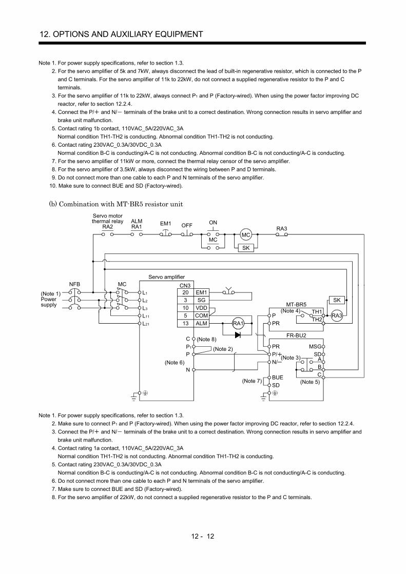
12 - 12
12. OPTIONS AND AUXILIARY EQUIPMENT
Note 1. For power supply specifications, refer to section 1.3.2. For the servo amplifier of 5k and 7kW, always disconnect the lead of built-in regenerative resistor, which is connected to the P
and C terminals. For the servo amplifier of 11k to 22kW, do not connect a supplied regenerative resistor to the P and Cterminals.
3. For the servo amplifier of 11k to 22kW, always connect P1 and P (Factory-wired). When using the power factor improving DCreactor, refer to section 12.2.4.
4. Connect the P/ and N/ terminals of the brake unit to a correct destination. Wrong connection results in servo amplifier andbrake unit malfunction.
5. Contact rating 1b contact, 110VAC_5A/220VAC_3ANormal condition TH1-TH2 is conducting. Abnormal condition TH1-TH2 is not conducting.
6. Contact rating 230VAC_0.3A/30VDC_0.3ANormal condition B-C is conducting/A-C is not conducting. Abnormal condition B-C is not conducting/A-C is conducting.
7. For the servo amplifier of 11kW or more, connect the thermal relay censor of the servo amplifier.8. For the servo amplifier of 3.5kW, always disconnect the wiring between P and D terminals.9. Do not connect more than one cable to each P and N terminals of the servo amplifier.
10. Make sure to connect BUE and SD (Factory-wired).
(b) Combination with MT-BR5 resistor unit
NFB
ALMRA1
MC
SKMC
ONOFFEM1Servo motorthermal relay
RA2
(Note 1)Powersupply
N/P/
BUESD
PR
BC
ASD
MSG
(Note 3)
(Note 5)
RA3
P1
P
N
FR-BU2
MT-BR5
Servo amplifier
PPR
TH2TH1(Note 4)
MC
RA3
(Note 6)
(Note 2)
L3
L11
L2
L21
L1
SK
(Note 7)
RA1RA1
105
SGVDDCOMALM
3
13
CN3EM120
C (Note 8)
Note 1. For power supply specifications, refer to section 1.3.2. Make sure to connect P1 and P (Factory-wired). When using the power factor improving DC reactor, refer to section 12.2.4.3. Connect the P/ and N/ terminals of the brake unit to a correct destination. Wrong connection results in servo amplifier and
brake unit malfunction.4. Contact rating 1a contact, 110VAC_5A/220VAC_3A
Normal condition TH1-TH2 is not conducting. Abnormal condition TH1-TH2 is conducting.5. Contact rating 230VAC_0.3A/30VDC_0.3A
Normal condition B-C is conducting/A-C is not conducting. Abnormal condition B-C is not conducting/A-C is conducting.6. Do not connect more than one cable to each P and N terminals of the servo amplifier.7. Make sure to connect BUE and SD (Factory-wired).8. For the servo amplifier of 22kW, do not connect a supplied regenerative resistor to the P and C terminals.
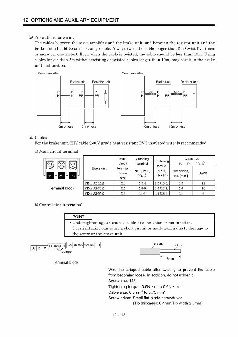
12 - 13
12. OPTIONS AND AUXILIARY EQUIPMENT
(c) Precautions for wiringThe cables between the servo amplifier and the brake unit, and between the resistor unit and thebrake unit should be as short as possible. Always twist the cable longer than 5m (twist five timesor more per one meter). Even when the cable is twisted, the cable should be less than 10m. Usingcables longer than 5m without twisting or twisted cables longer than 10m, may result in the brakeunit malfunction.
Servo amplifier
Brake unit
5m or less 5m or less
Servo amplifier
Brake unit
10m or less 10m or less
PN
PN
PPR PR
PN
PPR
PPR
Twist
Resistor unit Resistor unit
PN
TwistP
(d) CablesFor the brake unit, HIV cable (600V grade heat-resistant PVC insulated wire) is recommended.
a) Main circuit terminalCable sizeCrimping
terminal N/ , P/ , PR, Brake unit
Maincircuit
terminalscrewsize
N/ , P/ ,PR,
Tighteningtorque[N m]
([lb in])HIV cables,etc. [mm2]
AWG
FR-BU2-15K M4 5.5-4 1.5 (13.3) 3.5 12FR-BU2-30K M5 5.5-5 2.5 (22.1) 5.5 10
N/ P/ PR
Terminal blockFR-BU2-55K M6 14-6 4.4 (38.9) 14 6
b) Control circuit terminal
POINTUndertightening can cause a cable disconnection or malfunction.Overtightening can cause a short circuit or malfunction due to damage tothe screw or the brake unit.
ARESPC
BSDBUE
CMSGSD MSG SD SD
Jumper
Terminal block6mm
Sheath Core
Wire the stripped cable after twisting to prevent the cablefrom becoming loose. In addition, do not solder it.Screw size: M3Tightening torque: 0.5N m to 0.6N mCable size: 0.3mm2 to 0.75 mm2
Screw driver: Small flat-blade screwdriver (Tip thickness: 0.4mm/Tip width 2.5mm)

12 - 14
12. OPTIONS AND AUXILIARY EQUIPMENT
(e) Crimping terminals for P and N terminals of servo amplifier
POINTAlways use recommended crimping terminals or equivalent since somecrimping terminals cannot be installed depending on the size.
Servo amplifier Brake unitNumber ofconnected
unitsCrimping terminal (Manufacturer)
(Note)Applicable
tool
MR-J2S-350B FR-BU2-15K 1 FVD5.5-S4 bMR-J2S-500B FR-BU2-15K 1 (Japan Solderless Terminal)
FR-BU2-30K 1MR-J2S-700B FR-BU2-30K 1MR-J2S-11KB FR-BU2-30K 1 FVD5.5-6(Japan Solderless Terminal) b
FR-BU2-55K 1 FVD14-6(Japan Solderless Terminal) aMR-J2S-15KB FR-BU2-30K 1 FVD5.5-6(Japan Solderless Terminal) b
FR-BU2-55K 1 FVD14-6(Japan Solderless Terminal) aMR-J2S-22KB FR-BU2-55K 1 FVD14-8(Japan Solderless Terminal) a
Note. Symbols in the applicable tool field indicate the following applicable tools.
Symbol Applicable tool Manufacturer
aBodyHeadDice
YF-1 E-4YNE-38DH-112 DH-122
b YNT-1210S
Japan SolderlessTerminal
(4) Outline dimension drawings(a) FR-BU2 brake unit
[Unit: mm]
FR-BU2-15K
Ratingplate
5 hole(Screw size: M4)
686 56 6
518.5 52 62
4
132.5
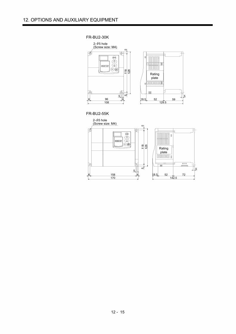
12 - 15
12. OPTIONS AND AUXILIARY EQUIPMENT
FR-BU2-30K
129.5
55918.5
Ratingplate
52
2- 5 hole(Screw size: M4)
5
1086 696
FR-BU2-55K
18.5
Ratingplate
52 72
5
142.5
561586
170
2- 5 hole(Screw size: M4)
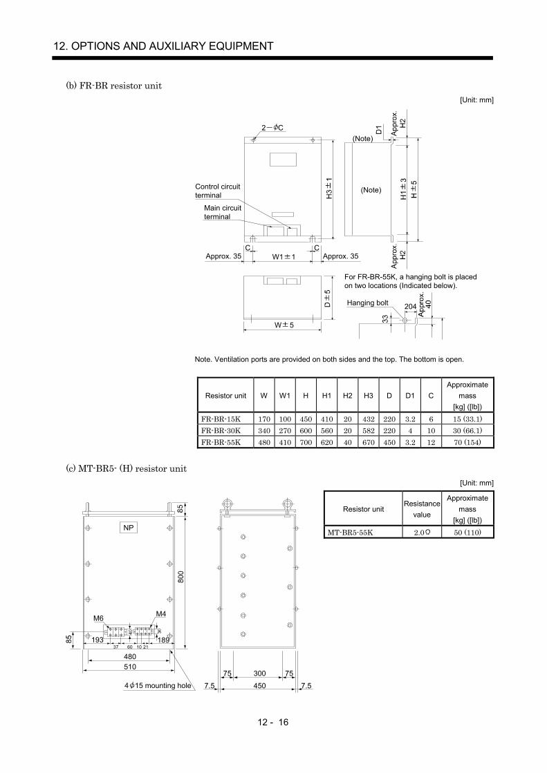
12 - 16
12. OPTIONS AND AUXILIARY EQUIPMENT
(b) FR-BR resistor unit[Unit: mm]
2 C
Control circuitterminal
Main circuitterminal
W1 1Approx. 35 Approx. 35
204Hanging bolt
C C
W 5
For FR-BR-55K, a hanging bolt is placedon two locations (Indicated below).
(Note)
(Note)
Note. Ventilation ports are provided on both sides and the top. The bottom is open.
Resistor unit W W1 H H1 H2 H3 D D1 CApproximate
mass[kg] ([lb])
FR-BR-15K 170 100 450 410 20 432 220 3.2 6 15 (33.1)FR-BR-30K 340 270 600 560 20 582 220 4 10 30 (66.1)FR-BR-55K 480 410 700 620 40 670 450 3.2 12 70 (154)
(c) MT-BR5- (H) resistor unit[Unit: mm]
Resistor unitResistance
value
Approximatemass
[kg] ([lb])
MT-BR5-55K 2.0 50 (110)
4 15 mounting hole30075 75
4507.5 7.5
M6 M4
193 189
480510
37 60 2110
NP

12 - 17
12. OPTIONS AND AUXILIARY EQUIPMENT
12.1.3 Power regeneration converter
When using the power regeneration converter, set " 01" in parameter No.2.
(1) SelectionThe converters can continuously return 75% of the nominal regenerative power. They are applied tothe servo amplifiers of the MR-J2S-500B to MR-J2S-22KB.
Power
regeneration
converter
Nominal
regenerative power
(kW)
Servo amplifier
FR-RC-15K 15MR-J2S-500BMR-J2S-700B
FR-RC-30K 30MR-J2S-11KBMR-J2S-15KB
FR-RC-55K 55 MR-J2S-22KB
0 50 75 100 150
500
300
200
100
50
3020
Con
tinuo
us e
nerg
izat
ion
time
[sec
]Nominal regenerative power (%)

12 - 18
12. OPTIONS AND AUXILIARY EQUIPMENT
(2) Connection example
NFB MC
Servo amplifier
L11
L21
L1
L2
L3
EM1
SG
Power regeneration converter FR-RC
SK
ON
MCB C
RDY
SE
Alarmoutput
RDYoutput
A
B
C
5m(16.4ft) or less
Operation ready
MCOFFEM1RA2
FR-RC
Ready
COM
VDD
R/L1
S/L2
T/L3
B
C
RX
R
SX
S
TX
T
N PC P1
N/ P/
(Note 5)Power supply
(Note 3) Power factor improving reactorFR-BAL
(Note 1)Phase detection terminals
(Note 4)
(Note 2)
Note 1. When not using the phase detection terminals, fit the jumpers across RX-R, SX-S and TX-T. If the jumpers remain removed, theFR-RC will not operate.
2. When using servo amplifiers of 5kW and 7kW, always remove the lead of built-in regenerative resistor connected to P terminaland C terminal.
3. For the power factor improving reactor (FR-BAL) to be used, refer to POWER REGENERATION CONVERTER FR-RCINSTRUCTION MANUAL (IB (NA) 67096). When using FR-BAL with the servo amplifier of 11 k to 22 kW, do not use with thepower factor improving reactor (FR-BAL).
4. When using the servo amplifier of 11k to 22kW, make sure to connect P1 and P. (Factory-wired.)5. Refer to section 1.3 for the power supply specification.
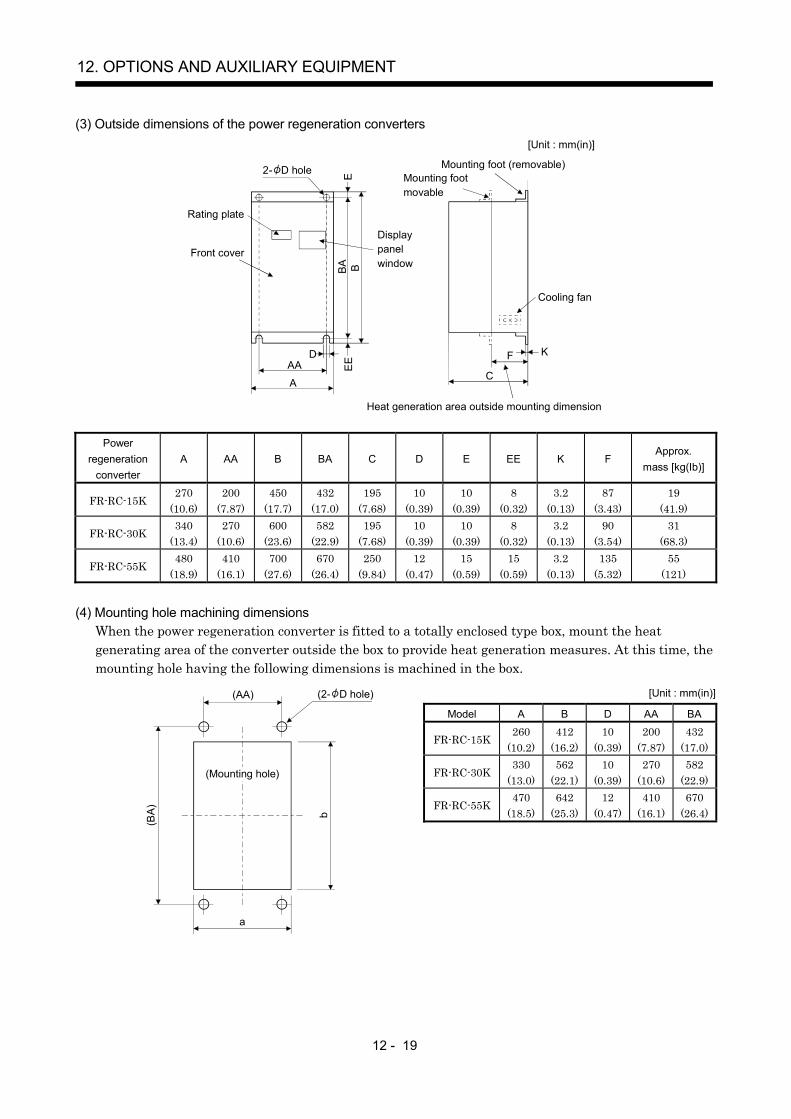
12 - 19
12. OPTIONS AND AUXILIARY EQUIPMENT
(3) Outside dimensions of the power regeneration converters[Unit : mm(in)]
AA
AC
F KE
EBA B
ED
2- D hole
Rating plate
Front cover
Displaypanelwindow
Mounting foot (removable)Mounting footmovable
Cooling fan
Heat generation area outside mounting dimension
Powerregeneration
converterA AA B BA C D E EE K F
Approx.mass [kg(Ib)]
FR-RC-15K270
(10.6)200
(7.87)450
(17.7)432
(17.0)195
(7.68)10
(0.39)10
(0.39)8
(0.32)3.2
(0.13)87
(3.43)19
(41.9)
FR-RC-30K340
(13.4)270
(10.6)600
(23.6)582
(22.9)195
(7.68)10
(0.39)10
(0.39)8
(0.32)3.2
(0.13)90
(3.54)31
(68.3)
FR-RC-55K480
(18.9)410
(16.1)700
(27.6)670
(26.4)250
(9.84)12
(0.47)15
(0.59)15
(0.59)3.2
(0.13)135
(5.32)55
(121)
(4) Mounting hole machining dimensionsWhen the power regeneration converter is fitted to a totally enclosed type box, mount the heatgenerating area of the converter outside the box to provide heat generation measures. At this time, themounting hole having the following dimensions is machined in the box.
[Unit : mm(in)]
Model A B D AA BA
FR-RC-15K260
(10.2)412
(16.2)10
(0.39)200
(7.87)432
(17.0)
FR-RC-30K330
(13.0)562
(22.1)10
(0.39)270
(10.6)582
(22.9)
FR-RC-55K470
(18.5)642
(25.3)12
(0.47)410
(16.1)670
(26.4)
(AA)
(BA) b
a
(2- D hole)
(Mounting hole)

12 - 20
12. OPTIONS AND AUXILIARY EQUIPMENT
12.1.4 External dynamic brake
POINTConfigure up a sequence which switches off the contact of the brake unitafter (or as soon as) it has turned off the servo on signal at a power failureor failure.For the braking time taken when the dynamic brake is operated, refer tosection 13.3.The brake unit is rated for a short duration. Do not use it for high duty.
(1) Selection of dynamic brakeThe dynamic brake is designed to bring the servo motor to a sudden stop when a power failure occursor the protective circuit is activated, and is built in the 7kW or less servo amplifier. Since it is not builtin the 11kW or more servo amplifier, purchase it separately if required. Set " 1 " in the parameterNo. 2.
Servo amplifier Dynamic brake
MR-J2S-11KB DBU-11KMR-J2S-15KB DBU-15KMR-J2S-22KB DBU-22K

12 - 21
12. OPTIONS AND AUXILIARY EQUIPMENT
(2) Connection example
MC
NFB MC
L11
L21
U
V
W
U
V
W
E
M
13 U14 V W
Dynamic brake
a
b
Servo amplifier
Servo motor
SK
MC
ONOFF(Note 1)
Operation-ready
RA1
RA1
EM1
EM1CON22
1
Plate
EM1
SG
SD
DB
CON215
18
VDD
COM
L3
L2
L1(Note 4)Power supply
4
P1
P(Note 3)
(Note 2)
Note 1. Configure up the circuit to switch power off in the external sequence at servo alarm occurrence. 2. Terminals 13, 14 are normally open contact outputs. If the dynamic brake is seized, terminals 13, 14 will open. Therefore, configure up an external sequence to prevent servo-on. 3. When using the servo amplifier of 11k to 22kW, make sure to connect P1 and P. (Factory-wired.) When using the power factor
improving DC reactor, refer to section 12.2.4. 4. Refer to section 1.3 for the power supply specification.
Servo motor rotation
Coasting
Alarm
RA1
ON
OFF
Forced stop(EM1)
Absent
Invalid
Valid
Short
Open
a. Timing chart at alarm occurrence b. Timing chart at forced stop (EM1) validity
Dynamic brake
Base
ON
OFF
Coasting
Dynamic brakeDynamic brake
Present

12 - 22
12. OPTIONS AND AUXILIARY EQUIPMENT
(3) Outline dimension drawing
U V W
D 100(3.94) D(0.2)5
C
E
G
F
2.3(0.09)
Terminal block
Screw : M3.5Screw : M4
B A
5(0.2) E
13 14E(GND) a b
[Unit: mm] ([Unit: in])
Tightening torque: 1.2 [N m](10.6 [lb in])Tightening torque: 0.8 [N m](7 [lb in])
Dynamic brake A B C D E F GMass
[kg]([Ib])Connectionwire [mm2]
DBU-11K200
(7.87)190
(7.48)140
(5.51)20
(0.79)5
(0.2)170
(6.69)163.5(6.44)
2 (4.41) 5.5
DBU-15K, 22K250
(9.84)238
(9.37)150
(5.91)25
(0.98)6
(0.24)235
(9.25)228
(8.98)6 (13.23) 5.5
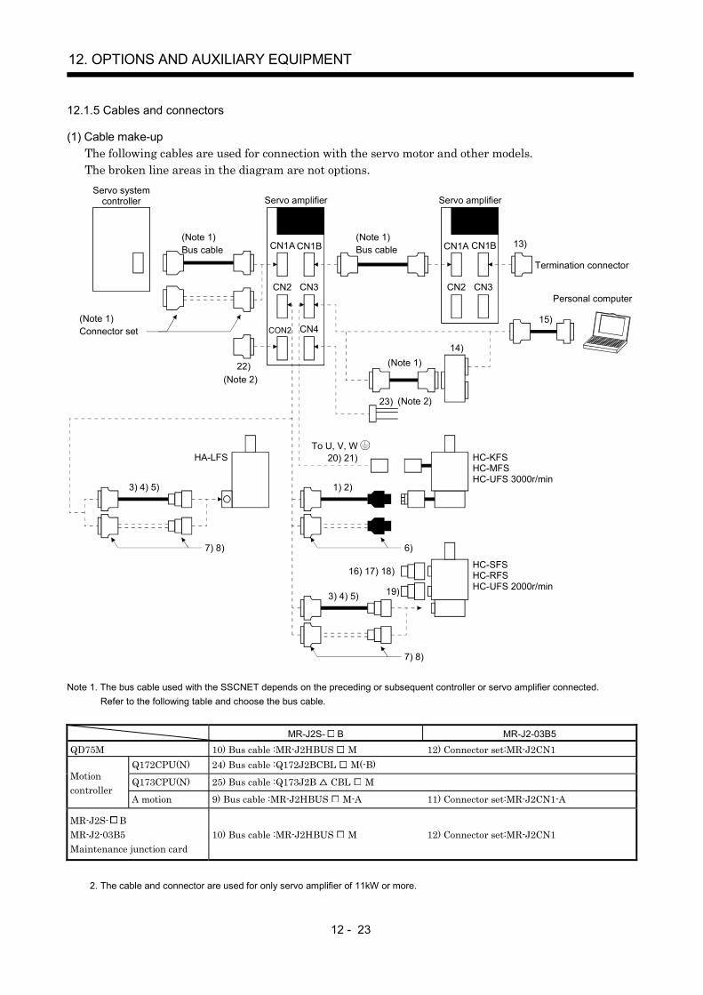
12 - 23
12. OPTIONS AND AUXILIARY EQUIPMENT
12.1.5 Cables and connectors
(1) Cable make-upThe following cables are used for connection with the servo motor and other models.The broken line areas in the diagram are not options.
HC-SFSHC-RFSHC-UFS 2000r/min
HC-KFSHC-MFSHC-UFS 3000r/min
1) 2)
6)
16) 17) 18)
20) 21)
19)
3) 4) 5)
7) 8)
To U, V, W
3) 4) 5)
7) 8)
HA-LFS
Personal computer
(Note 1)14)
15)
Servo amplifier
CN1A CN1B
CN2 CN3
Servo amplifier
(Note 1)Bus cable
(Note 1) Bus cable
Termination connector
13)
(Note 1)Connector set
CN1A CN1B
CN2 CN3
Servo system controller
CON2 CN4
23)
22)(Note 2)
(Note 2)
Note 1. The bus cable used with the SSCNET depends on the preceding or subsequent controller or servo amplifier connected.Refer to the following table and choose the bus cable.
MR-J2S- B MR-J2-03B5
QD75M 10) Bus cable :MR-J2HBUS M 12) Connector set:MR-J2CN1Q172CPU(N) 24) Bus cable :Q172J2BCBL M(-B)
Q173CPU(N) 25) Bus cable :Q173J2B CBL MMotioncontroller
A motion 9) Bus cable :MR-J2HBUS M-A 11) Connector set:MR-J2CN1-A
MR-J2S- BMR-J2-03B5Maintenance junction card
10) Bus cable :MR-J2HBUS M 12) Connector set:MR-J2CN1
2. The cable and connector are used for only servo amplifier of 11kW or more.
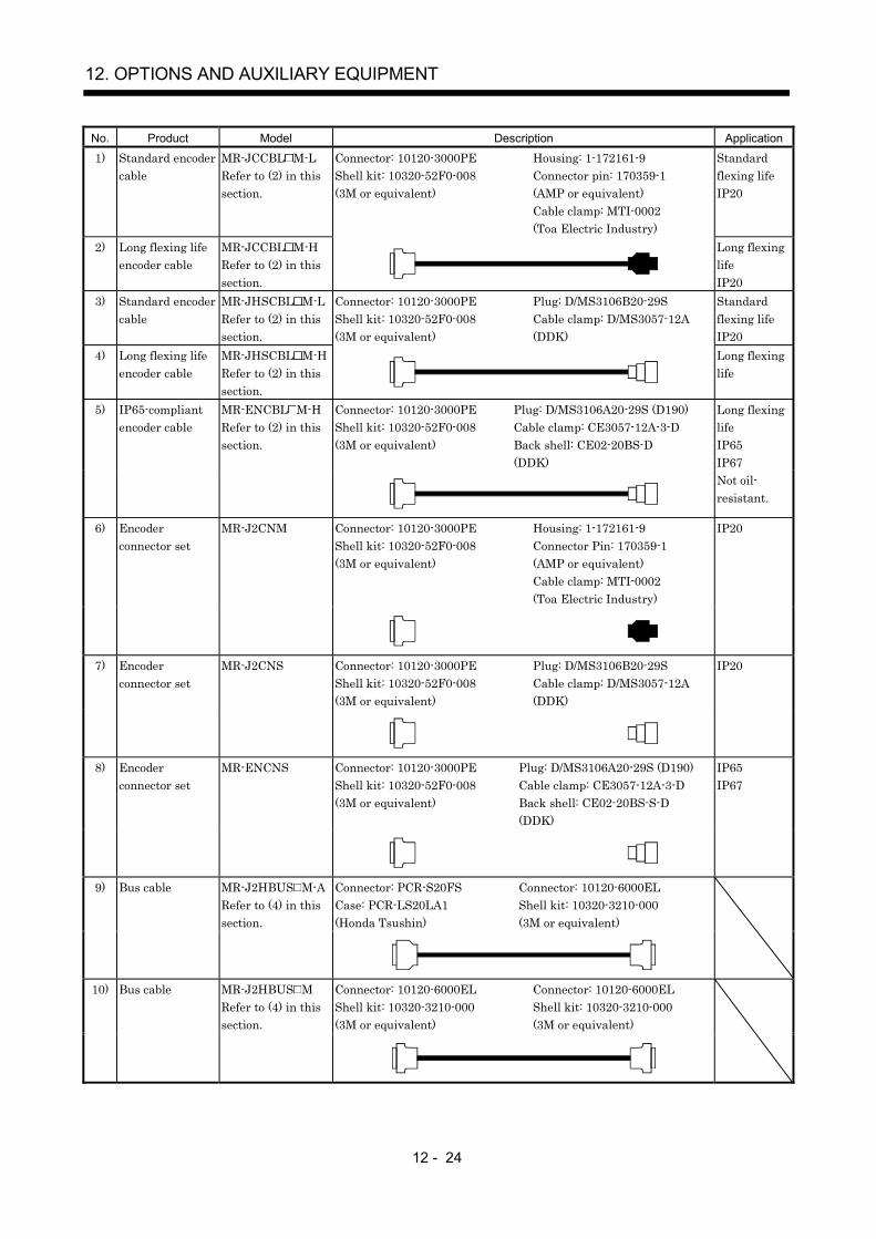
12 - 24
12. OPTIONS AND AUXILIARY EQUIPMENT
No. Product Model Description Application
1) Standard encodercable
MR-JCCBL M-LRefer to (2) in thissection.
Connector: 10120-3000PEShell kit: 10320-52F0-008(3M or equivalent)
Housing: 1-172161-9Connector pin: 170359-1(AMP or equivalent)Cable clamp: MTI-0002(Toa Electric Industry)
Standardflexing lifeIP20
2) Long flexing lifeencoder cable
MR-JCCBL M-HRefer to (2) in thissection.
Long flexinglifeIP20
3) Standard encodercable
MR-JHSCBL M-LRefer to (2) in thissection.
Connector: 10120-3000PEShell kit: 10320-52F0-008(3M or equivalent)
Plug: D/MS3106B20-29SCable clamp: D/MS3057-12A(DDK)
Standardflexing lifeIP20
4) Long flexing lifeencoder cable
MR-JHSCBL M-HRefer to (2) in thissection.
Long flexinglife
Connector: 10120-3000PEShell kit: 10320-52F0-008(3M or equivalent)
Plug: D/MS3106A20-29S (D190)Cable clamp: CE3057-12A-3-DBack shell: CE02-20BS-D(DDK)
5) IP65-compliantencoder cable
MR-ENCBL M-HRefer to (2) in thissection.
Long flexinglifeIP65IP67Not oil-resistant.
Connector: 10120-3000PEShell kit: 10320-52F0-008(3M or equivalent)
Housing: 1-172161-9Connector Pin: 170359-1(AMP or equivalent)Cable clamp: MTI-0002(Toa Electric Industry)
6) Encoderconnector set
MR-J2CNM IP20
Connector: 10120-3000PEShell kit: 10320-52F0-008(3M or equivalent)
Plug: D/MS3106B20-29SCable clamp: D/MS3057-12A(DDK)
7) Encoderconnector set
MR-J2CNS IP20
Connector: 10120-3000PEShell kit: 10320-52F0-008(3M or equivalent)
Plug: D/MS3106A20-29S (D190)Cable clamp: CE3057-12A-3-DBack shell: CE02-20BS-S-D(DDK)
8) Encoderconnector set
MR-ENCNS IP65IP67
Connector: PCR-S20FSCase: PCR-LS20LA1(Honda Tsushin)
Connector: 10120-6000ELShell kit: 10320-3210-000(3M or equivalent)
9) Bus cable MR-J2HBUS M-ARefer to (4) in thissection.
Connector: 10120-6000ELShell kit: 10320-3210-000(3M or equivalent)
Connector: 10120-6000ELShell kit: 10320-3210-000(3M or equivalent)
10) Bus cable MR-J2HBUS MRefer to (4) in thissection.
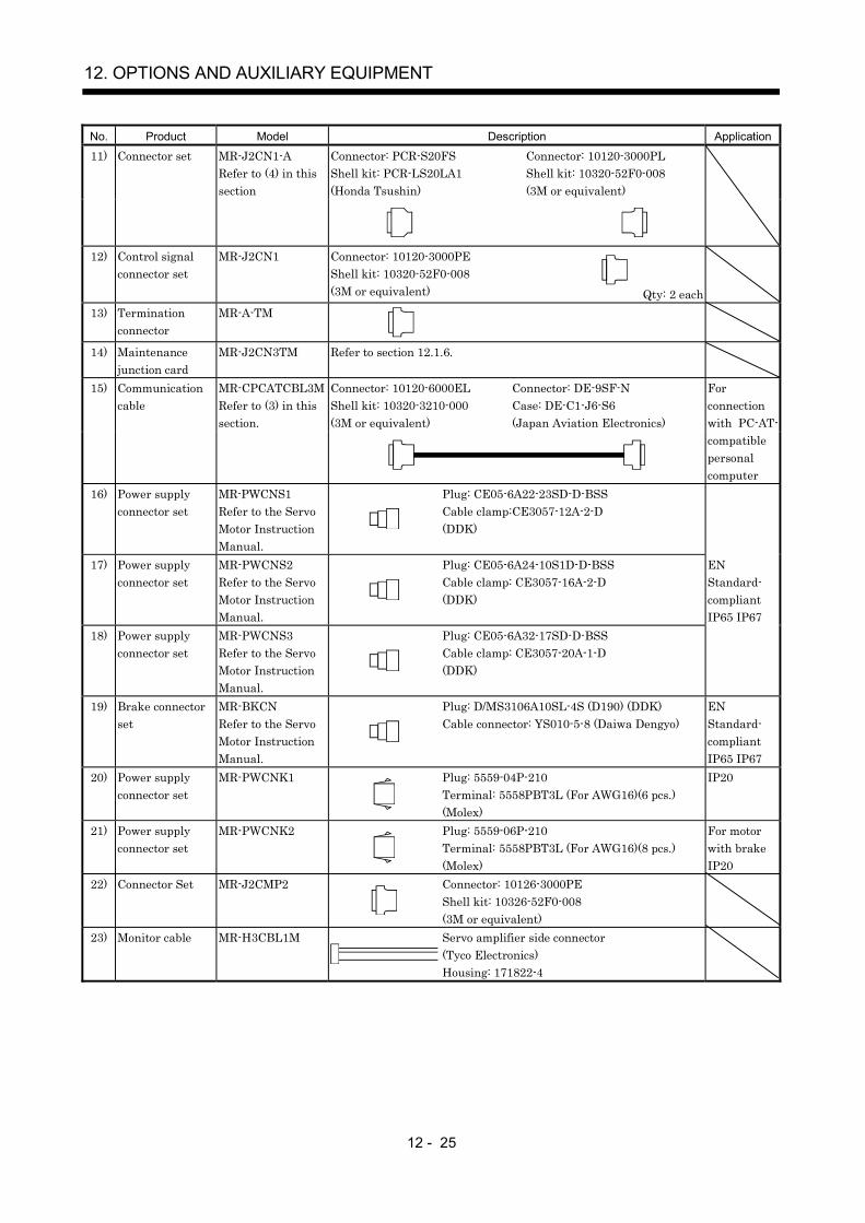
12 - 25
12. OPTIONS AND AUXILIARY EQUIPMENT
No. Product Model Description Application
Connector: PCR-S20FSShell kit: PCR-LS20LA1(Honda Tsushin)
Connector: 10120-3000PLShell kit: 10320-52F0-008(3M or equivalent)
11) Connector set MR-J2CN1-ARefer to (4) in thissection
12) Control signalconnector set
MR-J2CN1 Connector: 10120-3000PEShell kit: 10320-52F0-008(3M or equivalent) Qty: 2 each
13) Terminationconnector
MR-A-TM
14) Maintenancejunction card
MR-J2CN3TM Refer to section 12.1.6.
Connector: 10120-6000ELShell kit: 10320-3210-000(3M or equivalent)
Connector: DE-9SF-NCase: DE-C1-J6-S6(Japan Aviation Electronics)
15) Communicationcable
MR-CPCATCBL3MRefer to (3) in thissection.
Forconnectionwith PC-AT-compatiblepersonalcomputer
16) Power supplyconnector set
MR-PWCNS1Refer to the ServoMotor InstructionManual.
Plug: CE05-6A22-23SD-D-BSSCable clamp:CE3057-12A-2-D(DDK)
17) Power supplyconnector set
MR-PWCNS2Refer to the ServoMotor InstructionManual.
Plug: CE05-6A24-10S1D-D-BSSCable clamp: CE3057-16A-2-D(DDK)
18) Power supplyconnector set
MR-PWCNS3Refer to the ServoMotor InstructionManual.
Plug: CE05-6A32-17SD-D-BSSCable clamp: CE3057-20A-1-D(DDK)
ENStandard-compliantIP65 IP67
19) Brake connectorset
MR-BKCNRefer to the ServoMotor InstructionManual.
Plug: D/MS3106A10SL-4S (D190) (DDK)Cable connector: YS010-5-8 (Daiwa Dengyo)
ENStandard-compliantIP65 IP67
20) Power supplyconnector set
MR-PWCNK1 Plug: 5559-04P-210Terminal: 5558PBT3L (For AWG16)(6 pcs.)(Molex)
IP20
21) Power supplyconnector set
MR-PWCNK2 Plug: 5559-06P-210Terminal: 5558PBT3L (For AWG16)(8 pcs.)(Molex)
For motorwith brakeIP20
22) Connector Set MR-J2CMP2 Connector: 10126-3000PEShell kit: 10326-52F0-008(3M or equivalent)
23) Monitor cable MR-H3CBL1M Servo amplifier side connector(Tyco Electronics)Housing: 171822-4

12 - 26
12. OPTIONS AND AUXILIARY EQUIPMENT
No. Product Model Description Application
Connector: HDR-E14MG1Shell kit: HDR-E14LPA5(Honda Tsushin)
Connector: 10120-6000ELShell kit: 10320-3210-000(3M or equivalent)
(Note)
24) Bus cable Q172J2BCBL M(-B)Refer to (4) in thissection
Socket: HCN2-2.5S-2Terminal: HCN2-2.5S-D-B(Hirose Electric)Note. When using the battery unit Q170BAT, use the
Q172J2BCBL M-B.Connector: HDR-E26MG1Shell kit: HDR-E26LPA5(Honda Tsushin)
Connector: 10120-6000ELShell kit: 10320-3210-000(3M or equivalent)
25) Bus cable Q173J2B CBL MRefer to (4) in thissection

12 - 27
12. OPTIONS AND AUXILIARY EQUIPMENT
(2) Encoder cable
CAUTIONIf you have fabricated the encoder cable, connect it correctly.Otherwise, misoperation or explosion may occur.
POINTThe encoder cable is not oil resistant.Refer to section 11.4 for the flexing life of the encoder cable.When the encoder cable is used, the sum of the resistance values of thecable used for P5 and the cable used for LG should be within 2.4 .When soldering the wire to the connector pin, insulate and protect theconnection portion using heat-shrinkable tubing.
Generally use the encoder cable available as our options. If the required length is not found in theoptions, fabricate the cable on the customer side.
(a) MR-JCCBL M-L MR-JCCBL M-HThese encoder cables are used with the HC-KFS HC-MFS HC-UFS3000r/min series servomotors.
1) Model explanation
Long flexing lifeH
Symbol SpecificationsL Standard flexing life
Symbol (Note) Cable length [m(ft)]2 2 (6.56)5 5 (16.4)
10 10 (32.8)20 20 (65.6)30 30 (98.4)40 40 (131.2)50 50 (164.0)
Note. MR-JCCBL M-H has no 40(131.2ft) and 50m(164.0ft) sizes.
Model: MR-JCCBL M-
2) Connection diagramThe signal assignment of the encoder connector is as viewed from the pin side. For the pinassignment on the servo amplifier side, refer to section 3.2.1.
CN2
30cm(0.98ft)
Servo amplifier
Encoder connector
Encoder cable supplied to servo motor
Servo motor
Encoder
Encoder cable(option or fabricated)
1 2 3
4 5 6
7 8 9
MR MRR BAT
MD MDR
P5 LG SHD
Encoder connector1-172169-9 (Tyco Electronics)
50m(164.0ft) max.

12 - 28
12. OPTIONS AND AUXILIARY EQUIPMENT
P5LGP5LG
19112012
2
MRMRR
717
MDR 16 53
7
4
18P5LG
MD 6
LG 1BAT 9
SD
12
8
9
P5LGP5LG
19112012
2
MRMRR
717
MDR 16 53
7
4
MR-JCCBL2M-LMR-JCCBL5M-LMR-JCCBL2M-HMR-JCCBL5M-H
18P5LG
MD 6
LG 1BAT 9
SD
12
8
9
P5LGP5LG
19112012
2
MRMRR
717
MDR 16 53
7
4
18P5LG
MD 6
LG 1BAT 9
SD
12
8
9
Drive unit side Encoder side
Plate
Drive unit side Encoder side
Plate
Drive unit side Encoder side
Plate(Note) (Note) (Note)
Note. Always make connection for use in an absolute position detection system. This wiring is not needed for use in an incremental system.
MR-JCCBL10M-Lto
MR-JCCBL30M-L
MR-JCCBL10M-Hto
MR-JCCBL50M-H
When fabricating an encoder cable, use the recommended wires given in section 12.2.1 and theMR-J2CNM connector set for encoder cable fabrication, and fabricate an encoder cable as shownin the following wiring diagram. Referring to this wiring diagram, you can fabricate an encodercable of up to 50m(164.0ft) length including the length of the encoder cable supplied to the servomotor.When the encoder cable is to be fabricated by the customer, the wiring of MD and MDR is notrequired.Refer to chapter 3 of the servo motor instruction manual and choose the encode side connectoraccording to the servo motor installation environment.
Note. Always make connection for use in an absolute position detection system. This wiring is not needed for use in an incremental system.
19112012182
P5LGP5LGP5LG
717
91
MRMRR
BATLG
SD
812
3
7
9
For use of AWG22Drive unit side Encoder side
Plate(Note)
(3M)

12 - 29
12. OPTIONS AND AUXILIARY EQUIPMENT
(b) MR-JHSCBL M-L MR-JHSCBL M-H MR-ENCBL M-HThese encoder cables are used with the HC-SFS HC-RFS HC-UFS2000r/min series servo motors.
1) Model explanation
Long flexing lifeH
Symbol SpecificationsL Standard flexing life
Symbol (Note) Cable length [m(ft)]2 2 (6.56)5 5 (16.4)
10 10 (32.8)20 20 (65.6)30 30 (98.4)40 40 (131.2)50 50 (164.0)
Note. MR-JHSCBL M-L has no 40(131.2ft) and 50m(164.0ft) sizes.
Model: MR-JHSCBL M-
Symbol Cable length [m(ft)]2 2 (6.56)5 5 (16.4)10 10 (32.8)20 20 (65.6)30 30 (98.4)40 40 (131.2)50 50 (164.0)
Model: MR-ENCBL M-H
Long flexing life
2) Connection diagramFor the pin assignment on the servo amplifier side, refer to section 3.2.1.
CN2
A B C
DEFGH
JKL
M
Servo amplifier
50m(164.0ft) max.
Encoder connector
Servo motor
Encoder
Encoder connectorEncoder cable(Optional or fabricated)
RS
T PN
Pin SignalA MDB MDRC MRD MRREF BATG LGHJ
Pin SignalK
SHD
LMNPRST
LGP5
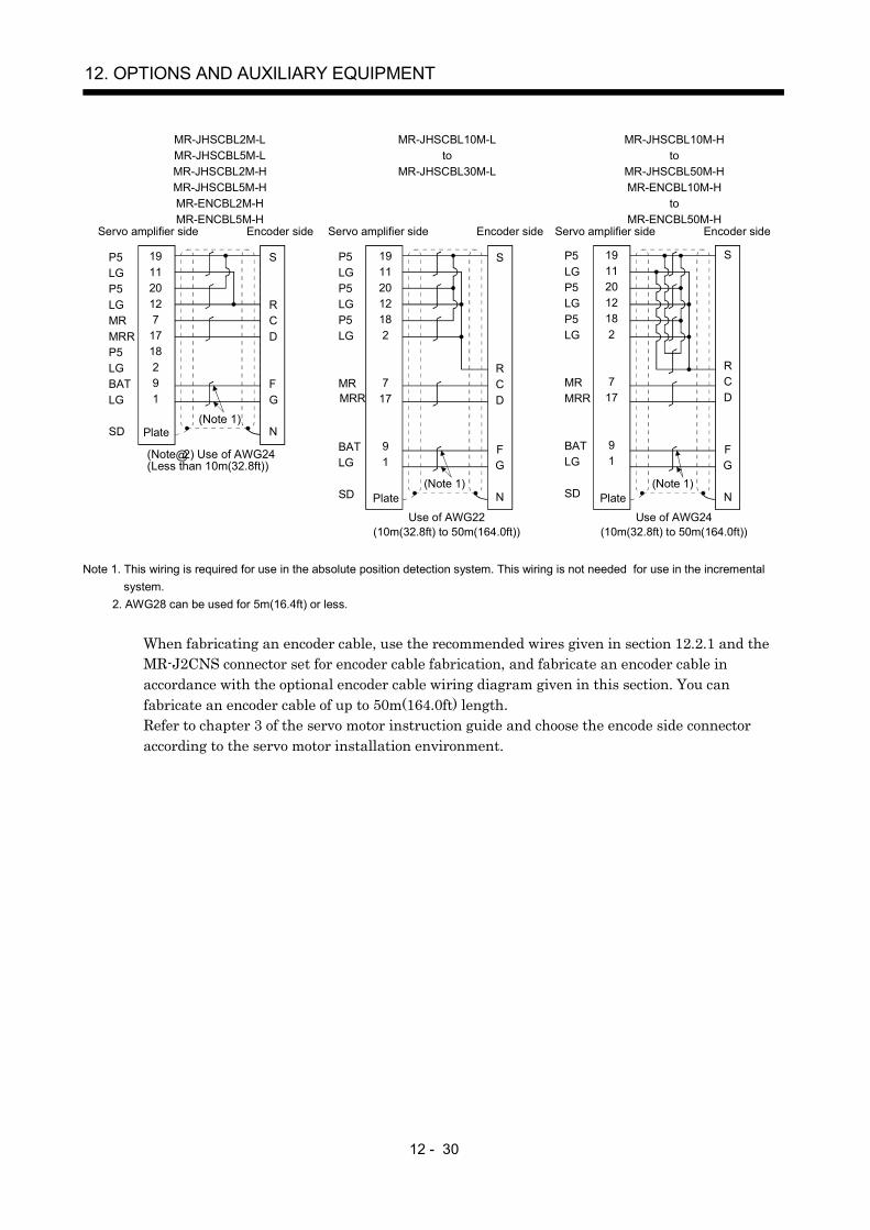
12 - 30
12. OPTIONS AND AUXILIARY EQUIPMENT
MR-JHSCBL2M-LMR-JHSCBL5M-LMR-JHSCBL2M-HMR-JHSCBL5M-HMR-ENCBL2M-HMR-ENCBL5M-H
MR-JHSCBL10M-Lto
MR-JHSCBL30M-L
MR-JHSCBL10M-Hto
MR-JHSCBL50M-HMR-ENCBL10M-H
toMR-ENCBL50M-H
Servo amplifier side Encoder side Servo amplifier side Encoder side Servo amplifier side Encoder side
Use of AWG22(10m(32.8ft) to 50m(164.0ft))
Use of AWG24(10m(32.8ft) to 50m(164.0ft))
(Note 1)Plate Plate
P5LGP5LGMRMRRP5LGBATLG
SD
191120127
1718291
Plate
S
R
FG
N
CD
P5LGP5LGP5LG
MRMRR
BATLG
SD
19112012182
717
91
S
RCD
F
N
G
P5LGP5LGP5LG
MRMRR
BATLG
SD
19112012182
717
91
S
RCD
F
N
G
(Note 1)
(Note�@2) Use of AWG24(Less than 10m(32.8ft))
(Note 1)
Note 1. This wiring is required for use in the absolute position detection system. This wiring is not needed for use in the incrementalsystem.
2. AWG28 can be used for 5m(16.4ft) or less.
When fabricating an encoder cable, use the recommended wires given in section 12.2.1 and theMR-J2CNS connector set for encoder cable fabrication, and fabricate an encoder cable inaccordance with the optional encoder cable wiring diagram given in this section. You canfabricate an encoder cable of up to 50m(164.0ft) length.Refer to chapter 3 of the servo motor instruction guide and choose the encode side connectoraccording to the servo motor installation environment.

12 - 31
12. OPTIONS AND AUXILIARY EQUIPMENT
(3) Communication cable
POINTThis cable may not be used with some personal computers. After fullyexamining the signals of the RS-232C connector, refer to this section andfabricate the cable.
(a) Model definitionModel: MR-CPCATCBL3M
Cable length 3[m](10[ft])
(b) Connection diagram
Half-pitch 20 pinsD-SUB9 pins
3
2 5 7 8 6 4
TXD
RXD GND RTS CTS DSR DTR
FG RXD
LGTXD
LG
Servo amplifier side
Plate 2 1
12 11
Personal computer sideMR-CPCATCBL3M
When fabricating the cable, refer to the connection diagram in this section.The following must be observed in fabrication.
1) Always use a shielded, multi-core cable and connect the shield with FG securely.
2) The optional communication cable is 3m(10ft) long. When the cable is fabricated, its maximumlength is 15m(49ft) in offices of good environment with minimal noise.
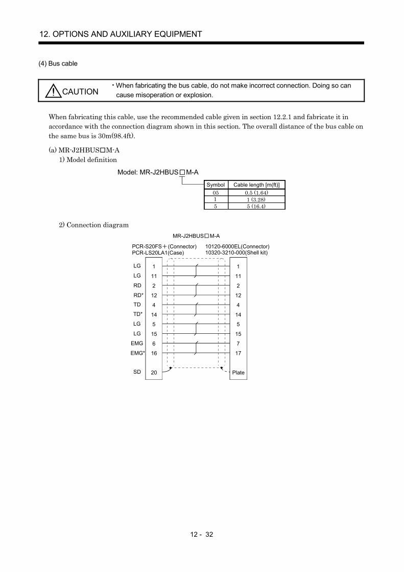
12 - 32
12. OPTIONS AND AUXILIARY EQUIPMENT
(4) Bus cable
CAUTIONWhen fabricating the bus cable, do not make incorrect connection. Doing so cancause misoperation or explosion.
When fabricating this cable, use the recommended cable given in section 12.2.1 and fabricate it inaccordance with the connection diagram shown in this section. The overall distance of the bus cable onthe same bus is 30m(98.4ft).
(a) MR-J2HBUS M-A1) Model definition
Model: MR-J2HBUS M-A
05Cable length [m(ft)]
5
Symbol0.5 (1.64)
5 (16.4)1 (3.28)1
2) Connection diagramMR-J2HBUS M-A
SD
LG
LG
RD
RD*
TD
TD*
LG
LG
EMG*
EMG
1
11
2
12
4
14
5
15
6
16
20 Plate
1
11
2
12
4
14
5
15
7
17
PCR-S20FS (Connector)PCR-LS20LA1(Case)
10120-6000EL(Connector)10320-3210-000(Shell kit)
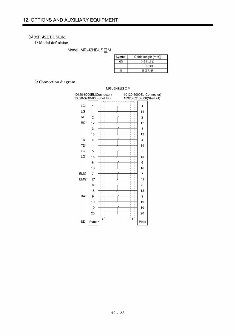
12 - 33
12. OPTIONS AND AUXILIARY EQUIPMENT
(b) MR-J2HBUS M1) Model definition
Symbol Cable length [m(ft)]05 0.5 (1.64)1 1 (3.28)5 5 (16.4)
Model: MR-J2HBUS M
2) Connection diagramMR-J2HBUS M
10120-6000EL(Connector)10320-3210-000(Shell kit)
10120-6000EL(Connector)10320-3210-000(Shell kit)
1
11
2
12
3
13
4
14
5
15
Plate
6
16
7
17
8
18
9
19
10
20
1
11
2
12
3
13
4
14
5
15
Plate
6
16
7
17
8
18
9
19
10
20
LG
RD*
LG
RD
TD
TD*
LG
LG
EMG
EMG*
BAT
SD

12 - 34
12. OPTIONS AND AUXILIARY EQUIPMENT
(c) Q172J2BCBL M(-B)When using the battery unit Q170BAT, use the Q172J2BCBL M-B. For the Q170BAT, refer tothe Motion Controller Q Series User's Manual (IB(NA)0300021).
1) Model definition
Yes-B
Symbol Connection of battery unitNo No
Symbol Cable length [m(ft)]05 0.5 (1.64)1 1 (3.28)
Model: Q172J2BCBL M-
5 5 (16.4)
2) Connection diagram
HDR-E14MG1(Connector)HDR-E14-LPA5(Connector case)
10120-6000EL(Connector)10320-3210-000(Shell kit)
Shell
8293106134
TD1TD1*LGLGRDRD*LGBTEMGEMG*SD
1 RD
Plate
121
114
14597
17
RD*LGLGTDTD*LGBTEMGEMG*SD
2
11
Q172J2BCBL M
HDR-E14MG1(Connector)HDR-E14-LPA5(Connector case)
10120-6000EL(Connector)10320-3210-000(Shell kit)
Shell
8293106134
TD1TD1*LGLGRDRD*LGBTEMGEMG*SD
1 RD
Plate
1211141459717
RD*LGLGTDTD*LGBTEMGEMG*SD
2
11
21BAT
LG
HCN2-2.5S-2(Socket)HNC2-2.5S-D-B(Terminal)
Q172J2BCBL M-B
(d) Q173J2B CBL M1) Model definition
Symbol SSCNET line numberNo SSCNET1 Line
Model: Q173J2B CBL MSymbol Cable length [m(ft)]
05 0.5 (1.64)1 1 (3.28)5 5 (16.4)
2 SSCNET2 Line3 SSCNET3 Line4 SSCNET4 Line

12 - 35
12. OPTIONS AND AUXILIARY EQUIPMENT
2) Connection diagram
HDR-E26MG1(Connector)HDR-E26-LPA5(Connector case)
10120-6000EL(Connector)10320-3210-000(Connector case)
143
162
1513266
TD1TD1*LGLGRD1RD1*LGBTEMG12EMG12*
1 RD
Plate
121
114
14597
17
RD*LGLGTDTD*LGBTEMGEMG*SD
2
19
RD
Plate
121
114
14597
17
RD*LGLGTDTD*LGBTEMGEMG*SD
2
RD
Plate
121
114
14597
17
RD*LGLGTDTD*LGBTEMGEMG*SD
2
RD
Plate
121
114
14597
17
RD*LGLGTDTD*LGBTEMGEMG*SD
2
17
518
TD2TD2*
RD2RD2*
4
209
228
21
12
TD3TD3*LGLGRD3RD3*
EMG34EMG34*
7
25
Shell
23
1124
TD4TD4*
RD4RD4*
SD
10
SSCNET1 Line
SSCNET2 Line
SSCNET3 Line
SSCNET4 Line
= No
= 2
= 3
= 4
Q173J2B CBL M When =4
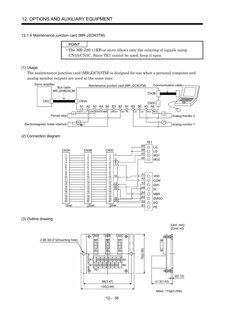
12 - 36
12. OPTIONS AND AUXILIARY EQUIPMENT
12.1.6 Maintenance junction card (MR-J2CN3TM)
POINTThe MR-J2S-11KB or more allows only the relaying of signals usingCN3A/CN3C. Since TE1 cannot be used, keep it open.
(1) UsageThe maintenance junction card (MR-J2CN3TM) is designed for use when a personal computer andanalog monitor outputs are used at the same time.
CN3B
CN3CCN3ACN3
A1 A2 A3 A4 B4 B3 B2 B1 B5 B6 A5 A6
Communication cableMaintenance junction card (MR-J2CN3TM)
Analog monitor 2
Analog monitor 1
Servo amplifierBus cable
MR-J2HBUS M
LGMBRVDD COM EM1DI MO1EMGO SG PE LG MO2
Forced stop
Electromagnetic brake interlockRA1
(2) Connection diagram
123456789
1011121314151617181920
1
345
10
131415
19
Shell
20
LG LG MO1 MO2
B5 B6A5
A6
TE1
CN3A
VDD COM EM1DIMBREMGOSG PE
A1 A2 A3
A4
B4
B3
B2 B1
123456789
1011121314151617181920
CN3B123456789
1011121314151617181920
CN3C
Shell Shell
(3) Outline drawing
3(0.12)
41.5(1.63)
75(2
.95)
88(3.47)
100(3.94)
MR
-J2C
N3T
M
CN3A CN3B CN3C
A1
B1
A6
B6
TE1
[Unit: mm]([Unit: in])
Mass: 110g(0.24Ib)
2- 5.3(0.21)(mounting hole)

12 - 37
12. OPTIONS AND AUXILIARY EQUIPMENT
12.1.7 Battery (MR-BAT, A6BAT)
POINTThe revision (Edition 44) of the Dangerous Goods Rule of theInternational Air Transport Association (IATA) went into effect onJanuary 1, 2003 and was enforced immediately. In this rule, "provisions ofthe lithium and lithium ion batteries" were revised to tighten therestrictions on the air transportation of batteries. However, since thisbattery is non-dangerous goods (non-Class 9), air transportation of 24 orless batteries is outside the range of the restrictions. Air transportation ofmore than 24 batteries requires packing compliant with the PackingStandard 903. When a self-certificate is necessary for battery safety tests,contact our branch or representative. For more information, consult ourbranch or representative. (As of November, 2007).
Use the battery to build an absolute position detection system.
12.1.8 MR Configurator (servo configurations software)
The MR Configurator (servo configuration software) uses the communication function of the servoamplifier to perform parameter setting changes, graph display, test operation, etc. on a personalcomputer.
(1) Specifications
Item Description
Communication signal Conforms to RS-232C.Baud rate [bps] 57600, 38400, 19200, 9600
MonitorDisplay, high speed monitor, trend graphMinimum resolution changes with the processing speed of the personal computer.
Alarm Display, history, amplifier data
DiagnosticDigital I/O, no motor rotation, total power-on time, amplifier version info, motor information,tuning data, absolute encoder data, Axis name setting.
Parameters Parameter list, turning, change list, detailed informationTest operation Jog operation, positioning operation, motor-less operation, Do forced output, program operation.
Advanced function Machine analyzer, gain search, machine simulation.File operation Data read, save, print
Others Automatic demo, help display

12 - 38
12. OPTIONS AND AUXILIARY EQUIPMENT
(2) System configuration(a) Components
To use this software, the following components are required in addition to the servo amplifier andservo motor.
Model (Note 1) Description
(Note 2)Personalcomputer
IBM PC-AT compatible where the English version of Windows® 95, Windows® 98, Windows® Me,Windows NT® Workstation 4.0, Windows® 2000 Professional, Windows® XP Professional and Windows®
XP Home Edition operatesProcessor: Pentium® 133MHz or more (Windows® 95, Windows® 98, Windows NT® Workstation 4.0,
Windows® 2000 Professional)Pentium® 150MHz or more (Windows® Me)Pentium® 300MHz or more (Windows® XP Professional, Windows® XP Home Edition)
Memory:16MB or more (Windows® 95)24MB or more (Windows® 98)32MB or more (Windows® Me, Windows NT® Workstation 4.0, Windows® 2000 Professional)128MB or more (Windows® XP Professional, Windows® XP Home Edition)
Free hard disk space: 60MB or moreSerial port used
OS Windows® 95, Windows® 98, Windows® Me, Windows NT® Workstation 4.0, Windows® 2000 Professional(English version)
Display One whose resolution is 800 600 or more and that can provide a high color (16 bit) display.Connectable with the above personal computer.
Keyboard Connectable with the above personal computer.Mouse Connectable with the above personal computer. Note that a serial mouse is not used.Printer Connectable with the above personal computer.
Communicationcable
MR-CPCATCBL3MWhen this cannot be used, refer to section 12.1.5 (3) and fabricate.
Note 1. Windows and Windows NT are the registered trademarks of Microsoft Corporation in the United State and other countries.Pentium is the registered trademarks of Intel Corporation.
2. On some personal computers, this software may not run properly.
(b) Configuration diagram
CN3 CN2
Personal computer
To RS-232Cconnector
Communication cable
Servo amplifier
Servo motor
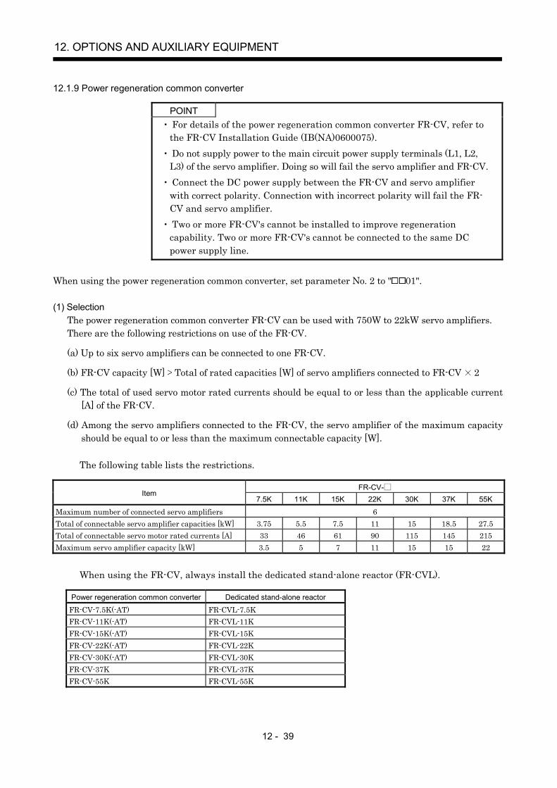
12 - 39
12. OPTIONS AND AUXILIARY EQUIPMENT
12.1.9 Power regeneration common converter
POINT For details of the power regeneration common converter FR-CV, refer tothe FR-CV Installation Guide (IB(NA)0600075). Do not supply power to the main circuit power supply terminals (L1, L2,L3) of the servo amplifier. Doing so will fail the servo amplifier and FR-CV. Connect the DC power supply between the FR-CV and servo amplifierwith correct polarity. Connection with incorrect polarity will fail the FR-CV and servo amplifier. Two or more FR-CV's cannot be installed to improve regenerationcapability. Two or more FR-CV's cannot be connected to the same DCpower supply line.
When using the power regeneration common converter, set parameter No. 2 to " 01".
(1) SelectionThe power regeneration common converter FR-CV can be used with 750W to 22kW servo amplifiers.There are the following restrictions on use of the FR-CV.
(a) Up to six servo amplifiers can be connected to one FR-CV.
(b) FR-CV capacity [W] Total of rated capacities [W] of servo amplifiers connected to FR-CV 2
(c) The total of used servo motor rated currents should be equal to or less than the applicable current[A] of the FR-CV.
(d) Among the servo amplifiers connected to the FR-CV, the servo amplifier of the maximum capacityshould be equal to or less than the maximum connectable capacity [W].
The following table lists the restrictions.
FR-CV-Item
7.5K 11K 15K 22K 30K 37K 55K
Maximum number of connected servo amplifiers 6Total of connectable servo amplifier capacities [kW] 3.75 5.5 7.5 11 15 18.5 27.5Total of connectable servo motor rated currents [A] 33 46 61 90 115 145 215Maximum servo amplifier capacity [kW] 3.5 5 7 11 15 15 22
When using the FR-CV, always install the dedicated stand-alone reactor (FR-CVL).
Power regeneration common converter Dedicated stand-alone reactor
FR-CV-7.5K(-AT) FR-CVL-7.5KFR-CV-11K(-AT) FR-CVL-11KFR-CV-15K(-AT) FR-CVL-15KFR-CV-22K(-AT) FR-CVL-22KFR-CV-30K(-AT) FR-CVL-30KFR-CV-37K FR-CVL-37KFR-CV-55K FR-CVL-55K
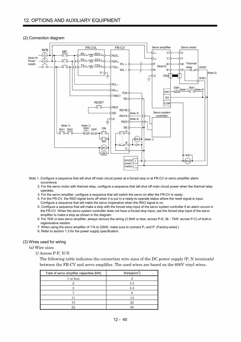
12 - 40
12. OPTIONS AND AUXILIARY EQUIPMENT
(2) Connection diagram
R2/L12
RA1EM1
C
B
R/L11
S/L21
T/L31
R2/L1
S2/L22
T2/L32
S2/L2
N/L
P24
SD
RDYB
RDYA
RSO
SEA
P/L T2/L3
R/L11
S/L21
T/MC1
RES
SD
L11
L21
P
N
SG
COM
U
V
W
EM1(Note 1)
RA1
RA224VDC power supply
U
V
W Thermal relay 0HS2
0HS1CN2
MCNFBFR-CVL FR-CV
MC
RA1 RA2 EM1 OFF ON
RESET
SK
MC
Servo motorServo amplifier
Servo system controller
(Note 5)
(Note 2)
(Note 3)
(Note 4)
(Note 1)(Note 1)
(Note 1)
(Note 6)
(Note 8)Power supply
Note 1. Configure a sequence that will shut off main circuit power at a forced stop or at FR-CV or servo amplifier alarmoccurrence.
2. For the servo motor with thermal relay, configure a sequence that will shut off main circuit power when the thermal relayoperates.
3. For the servo amplifier, configure a sequence that will switch the servo on after the FR-CV is ready.4. For the FR-CV, the RSO signal turns off when it is put in a ready-to-operate status where the reset signal is input.
Configure a sequence that will make the servo inoperative when the RSO signal is on.5. Configure a sequence that will make a stop with the forced stop input of the servo system controller if an alarm occurs in
the FR-CV. When the servo system controller does not have a forced stop input, use the forced stop input of the servoamplifier to make a stop as shown in the diagram.
6. For 7kW or less servo amplifier, always remove the wiring (3.5kW or less: across P-D, 5k 7kW: across P-C) of built-inregenerative resistor.
7. When using the servo amplifier of 11k to 22kW, make sure to connect P1 and P. (Factory-wired.)8. Refer to section 1.3 for the power supply specification.
(3) Wires used for wiring(a) Wire sizes
1) Across P-P, N-NThe following table indicates the connection wire sizes of the DC power supply (P, N terminals)between the FR-CV and servo amplifier. The used wires are based on the 600V vinyl wires.
Total of servo amplifier capacities [kW] Wires[mm2]
1 or less 22 3.55 5.57 8
11 1415 2222 50
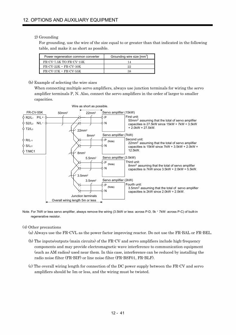
12 - 41
12. OPTIONS AND AUXILIARY EQUIPMENT
2) GroundingFor grounding, use the wire of the size equal to or greater than that indicated in the followingtable, and make it as short as possible.
Power regeneration common converter Grounding wire size [mm2]
FR-CV-7.5K TO FR-CV-15K 14FR-CV-22K • FR-CV-30K 22FR-CV-37K • FR-CV-55K 38
(b) Example of selecting the wire sizesWhen connecting multiple servo amplifiers, always use junction terminals for wiring the servoamplifier terminals P, N. Also, connect the servo amplifiers in the order of larger to smallercapacities.
R2/L1
S2/L2
T2/L3
R/L11
S/L21
T/MC1
P/L
N/L
P
N
50mm2
Overall wiring length 5m or less
First unit: 50mm assuming that the total of servo amplifier capacities is 27.5kW since 15kW + 7kW + 3.5kW + 2.0kW = 27.5kW.
P
N
P
N
P
N
22mm2
8mm2
3.5mm2
22mm2
8mm2
5.5mm2
3.5mm2
Junction terminals
Wire as short as possible.
Second unit: 22mm assuming that the total of servo amplifier capacities is 15kW since 7kW + 3.5kW + 2.0kW = 12.5kW.
Third unit: 8mm assuming that the total of servo amplifier capacities is 7kW since 3.5kW + 2.0kW = 5.5kW.
Fourth unit: 3.5mm assuming that the total of servo amplifier capacities is 2kW since 2.0kW = 2.0kW.
FR-CV-55K Servo amplifier (15kW)
Servo amplifier (7kW)
Servo amplifier (3.5kW)
Servo amplifier (2kW)
2
2
2
2
(Note)
(Note)
(Note)
Note. For 7kW or less servo amplifier, always remove the wiring (3.5kW or less: across P-D, 5k 7kW: across P-C) of built-inregenerative resistor.
(4) Other precautions(a) Always use the FR-CVL as the power factor improving reactor. Do not use the FR-BAL or FR-BEL.
(b) The inputs/outputs (main circuits) of the FR-CV and servo amplifiers include high-frequencycomponents and may provide electromagnetic wave interference to communication equipment(such as AM radios) used near them. In this case, interference can be reduced by installing theradio noise filter (FR-BIF) or line noise filter (FR-BSF01, FR-BLF).
(c) The overall wiring length for connection of the DC power supply between the FR-CV and servoamplifiers should be 5m or less, and the wiring must be twisted.

12 - 42
12. OPTIONS AND AUXILIARY EQUIPMENT
(5) Specifications
Power regeneration common converterFR-CV-
Item7.5K 11K 15K 22K 30K 37K 55K
Total of connectable servo amplifier capacities [kW] 3.75 5.5 7.5 11 15 18.5 27.5Maximum servo amplifier capacity [kW] 3.5 5 7 11 15 15 22
Total of connectable servo motor ratedcurrents [A]
33 46 61 90 115 145 215
Short-timerating
Total capacity of applicable servo motors, 300% torque, 60s (Note 1)OutputRegenerativebraking torque Continuous
rating100% torque
Rated input AC voltage/frequency Three-phase 200 to 220V 50Hz, 200 to 230V 60HzPermissible AC voltage fluctuation Three-phase 170 to 242V 50Hz, 170 to 253V 60HzPermissible frequency fluctuation 5%
Power supply
Power supply capacity (Note 2) [kVA] 17 20 28 41 52 66 100Protective structure (JEM 1030), cooling system Open type (IP00), forced cooling
Ambient temperature 10 to 50 (14 to 122 )(non-freezing)Ambient humidity 90%RH or less (non-condensing)EnvironmentAmbience Indoors (without corrosive gas, flammable gas, oil mist, dust and dirt)
Altitude, vibration 1000m or less above sea level, 5.9m/s2 or less
No-fuse breaker or leakage current breaker30AF30A
50AF50A
100AF75A
100AF100A
225AF125A
225AF125A
225AF175A
Magnetic contactor S-N20 S-N35 S-N50 S-N65 S-N95 S-N95 S-N125Note 1. This is the time when the protective function of the FR-CV is activated. The protective function of the servo amplifier is activated
in the time indicated in section 11.1. 2. When connecting the capacity of connectable servo amplifier, specify the value of servo amplifier.

12 - 43
12. OPTIONS AND AUXILIARY EQUIPMENT
12.1.10 Heat sink outside mounting attachment (MR-JACN)
Use the heat sink outside mounting attachment to mount the heat generation area of the servo amplifierin the outside of the control box to dissipate servo amplifier-generated heat to the outside of the box andreduce the amount of heat generated in the box, thereby allowing a compact control box to be designed.In the control box, machine a hole having the panel cut dimensions, fit the heat sink outside mountingattachment to the servo amplifier with the fitting screws (4 screws supplied), and install the servoamplifier to the control box.The environment outside the control box when using the heat sink outside mounting attachment shouldbe within the range of the servo amplifier operating environment conditions.
(1) Panel cut dimensions
[Unit: mm(in)]Changeable
dimension
Model
A B C D Servo amplifier
MR-JACN15K236
(9.291)255
(10.039)270
(10.63)203
(7.992)MR-J2S-11KBMR-J2S-15KB
MR-JACN22K326
(12.835)345
(13.583)360
(14.173)290
(11.417)MR-J2S-22KB
A
B
C
125
(4.9
21)
331
(13.
031)
39.5
(1.5
55)
535
(21.
063)
510
(20.
079)
18(0
.709
)
D 4-M10 Screw
Punchedhole
39.5
(1.5
55)
(2) How to assemble the attachment for a heat sink outside mounting attachment
AttachmentScrew
(4 places)AttachmentScrew
(2 places)
MR-JACN15K MR-JACN22K

12 - 44
12. OPTIONS AND AUXILIARY EQUIPMENT
(3) Fitting method
Attachment
Fit using the assembling screws.
Servoamplifier
Attachment
Servoamplifier
Punched hole
Control box
a. Assembling the heat sink outside mounting attachment b. Installation to the control box
(4) Outline dimension drawing(a) MR-JACN15K (MR-J2S-11KB, MR-J2S-15KB)
Servo amplifier
Attachment
Panel
Panel
20 (0.787)
145
(5.7
09)
400
(15.
748)
35(1
.378
)
194
(7.6
38)
84(3
.307
)
58(2
.283
)12
(0.4
72)
3.2 (0.126)
236 (9.291)
155 (6.102) 11.5(0.453)
260(10.236)
280 (11.024)
260 (10.236)
510
(20.
079)
580
(22.
835)
Servo amplifier
4- 12Mounting hole
Attachment
105(4.134)

12 - 45
12. OPTIONS AND AUXILIARY EQUIPMENT
(b) MR-JACN22K (MR-J2S-22KB)68(2.677)
145(
5.70
9)40
0(15
.748
)35
(1.3
78)
194(
7.63
8)84
5812
3.2(0.126)
326(12.835)
155(6.102) 105 11.5
260
370(14.567)
350(13.78)
510(
20.0
79)
580(
22.8
35)
Attachment
Servo amplifier
Attachment
4- 12Mounting hole
Servo amplifier
Panel
Panel
(2.2
83)
(0.4
72) (3
.307
)
(10.236)
(4.134) (0.453)

12 - 46
12. OPTIONS AND AUXILIARY EQUIPMENT
12.2 Auxiliary equipment
Always use the devices indicated in this section or equivalent. To comply with the EN Standard or UL/C-UL (CSA) Standard, use the products which conform to the corresponding standard.
12.2.1 Recommended wires
(1) Wires for power supply wiringThe following diagram shows the wires used for wiring. Use the wires given in this section or equivalent.
C
P
U
V
W
L11
L21
B1
B2
U
V
W
L1
L2
L3 Motor
N
1) Main circuit power supply lead
Power supply
3) Motor power supply lead
Electro-magnetic brake
Encoder
5) Electromagnetic brake lead2) Control power supply lead
Cooling fan
BU
BV
BW
Cooling fan lead
Power supply
Regenerative option
4) Regenerative option leadEncoder cable (refer to section 12.1.4)
Servo motorServo amplifier
4) Power regeneration converter lead
Power regeneration converter
The following table lists wire sizes. The wires used assume that they are 600V vinyl wires and thewiring distance is 30m(98.4ft) max. If the wiring distance is over 30m(98.4ft), choose the wire size inconsideration of voltage drop.The alphabets (a, b, c) in the table correspond to the crimping terminals (Table 12.2) used to wire theservo amplifier. For connection with the terminal block TE2 of the MR-J2S-100B or less, refer tosection 3.9.The servo motor side connection method depends on the type and capacity of the servo motor. Refer tosection 3.6.To comply with the UL/C-UL (CSA) Standard, use UL-recognized copper wires rated at 60 (140 ) ormore for wiring.

12 - 47
12. OPTIONS AND AUXILIARY EQUIPMENT
Table 12.1 Recommended wires(Note 1) Wires [mm2]
Servo amplifier1) L1 L2 L3 2) L11 L21 3) U V W P1 P 4) P C N 5) B1 B2 6) BU BV BW
MR-J2S-10B(1)MR-J2S-20B(1)MR-J2S-40B(1)MR-J2S-60BMR-J2S-70B
1.25 (AWG16) : a
MR-J2S-100B
2 (AWG14) : a
2 (AWG14) : aMR-J2S-200B 3.5 (AWG12) : b 3.5 (AWG12) : b
MR-J2S-350B (Note 2)5.5 (AWG10) : b
MR-J2S-500B5.5 (AWG10) : b
5.5 (AWG10) : b
2 (AWG14) : a
MR-J2S-700B 8 (AWG8) : c 8 (AWG8) : c 3.5(AWG12): bMR-J2S-11KB 14 (AWG6) :d 22 (AWG4) :eMR-J2S-15KB 22 (AWG4) :e 30 (AWG2) :fMR-J2S-22KB 50 (AWG1/0) :g
1.25(AWG16)
60 (AWG2/0) :g5.5(AWG10): b
1.25 (AWG16)
2(AWG14)
Note 1. For the crimping terminals and applicable tools, see the table 12.2.2. 3.5mm2 for use of the HC-RFS203 servo motor.
Use wires 6) of the following sizes with the power regeneration converter (FR-RC).
Model Wires[mm2]FR-RC-15K 14(AWG6)FR-RC-30K 14(AWG6)FR-RC-55K 22(AWG4)
Table 12.2 Recommended crimping terminalsServo amplifier side crimping terminals
SymbolCrimping terminal Applicable tool Manufacturer name
a 32959 47387 Tyco Electronicsb FVD5.5-4 YNT-1210S
c FVD8-5Body YF-1 E-4Head YNE-38Dice DH-111 DH-121
d FVD14-6Body YF-1 E-4Head YNE-38Dice DH-112 DH-122
e FVD22-6Body YF-1 E-4Head YNE-38Dice DH-113 DH-123Body YPT-60-21Dice TD-124 TD-112
38-S6 Body YF-1 E-4Head YET-60-1Dice TD-124 TD-112
Japan SolderlessTerminal
(Note 1 2)f
R38-6S NOP60NOM60 NICHIFU
Body YDT-60-21Dice TD-125 TD-113
g (Note 1)R60-8 Body YF-1 E-4Head YET-60-1Dice TD-125 TD-113
Japan SolderlessTerminal
Note 1. Cover the crimped portion with an insulating tape.2. Always use recommended crimping terminals or equivalent since some crimping terminals cannot be installed depending on the
size.
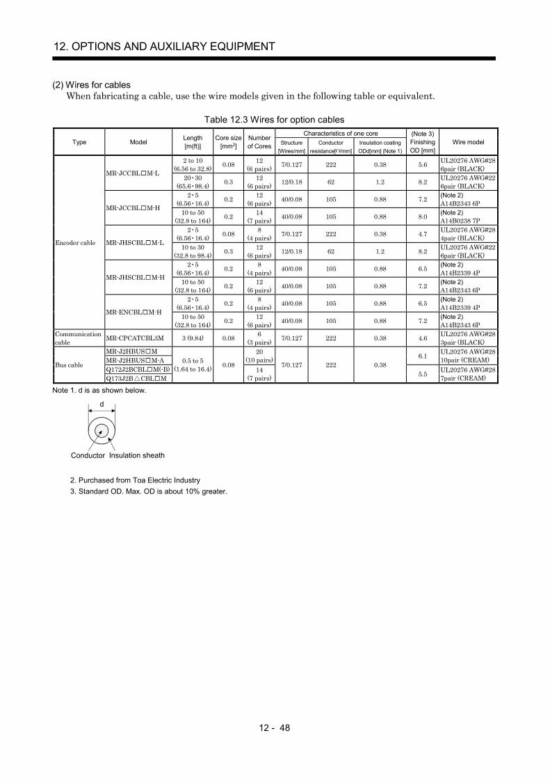
12 - 48
12. OPTIONS AND AUXILIARY EQUIPMENT
(2) Wires for cablesWhen fabricating a cable, use the wire models given in the following table or equivalent.
Table 12.3 Wires for option cablesCharacteristics of one core
Type Model Length[m(ft)]
Core size[mm2]
Numberof Cores Structure
[Wires/mm]Conductor
resistance[ /mm]Insulation coatingODd[mm] (Note 1)
(Note 3)FinishingOD [mm]
Wire model
2 to 10(6.56 to 32.8) 0.08 12
(6 pairs) 7/0.127 222 0.38 5.6 UL20276 AWG#286pair (BLACK)MR-JCCBL M-L 20 30
(65.6 98.4) 0.3 12(6 pairs) 12/0.18 62 1.2 8.2 UL20276 AWG#22
6pair (BLACK)2 5
(6.56 16.4) 0.2 12(6 pairs) 40/0.08 105 0.88 7.2 (Note 2)
A14B2343 6PMR-JCCBL M-H 10 to 50(32.8 to 164) 0.2 14
(7 pairs) 40/0.08 105 0.88 8.0 (Note 2)A14B0238 7P
2 5(6.56 16.4) 0.08 8
(4 pairs) 7/0.127 222 0.38 4.7 UL20276 AWG#284pair (BLACK)MR-JHSCBL M-L 10 to 30
(32.8 to 98.4) 0.3 12(6 pairs) 12/0.18 62 1.2 8.2 UL20276 AWG#22
6pair (BLACK)2 5
(6.56 16.4) 0.2 8(4 pairs) 40/0.08 105 0.88 6.5 (Note 2)
A14B2339 4PMR-JHSCBL M-H 10 to 50(32.8 to 164) 0.2 12
(6 pairs) 40/0.08 105 0.88 7.2 (Note 2)A14B2343 6P
2 5(6.56 16.4) 0.2 8
(4 pairs) 40/0.08 105 0.88 6.5 (Note 2)A14B2339 4P
Encoder cable
MR-ENCBL M-H 10 to 50(32.8 to 164) 0.2 12
(6 pairs) 40/0.08 105 0.88 7.2 (Note 2)A14B2343 6P
Communicationcable MR-CPCATCBL3M 3 (9.84) 0.08 6
(3 pairs) 7/0.127 222 0.38 4.6 UL20276 AWG#283pair (BLACK)
MR-J2HBUS MMR-J2HBUS M-A
20(10 pairs) 6.1 UL20276 AWG#28
10pair (CREAM)Q172J2BCBL M(-B)Bus cable
Q173J2B CBL M
0.5 to 5(1.64 to 16.4) 0.08
14(7 pairs)
7/0.127 222 0.385.5 UL20276 AWG#28
7pair (CREAM)
Note 1. d is as shown below.
d
Conductor Insulation sheath
2. Purchased from Toa Electric Industry3. Standard OD. Max. OD is about 10% greater.

12 - 49
12. OPTIONS AND AUXILIARY EQUIPMENT
12.2.2 No-fuse breakers, fuses, magnetic contactors
Always use one no-fuse breaker and one magnetic contactor with one servo amplifier. When using a fuseinstead of the no-fuse breaker, use the one having the specifications given in this section.
FuseServo amplifier No-fuse breakerClass Current [A] Voltage AC[V]
Magnetic contactor
MR-J2S-10B(1) 30A frame 5A K5 10MR-J2S-20B 30A frame 5A K5 10MR-J2S-40B 20B1 30A frame 10A K5 15MR-J2S-60B 40B1 30A frame 15A K5 20MR-J2S-70B 30A frame 15A K5 20MR-J2S-100B 30A frame 15A K5 25
S-N10
MR-J2S-200B 30A frame 20A K5 40 S-N18MR-J2S-350B 30A frame 30A K5 70 S-N20MR-J2S-500B 50A frame 50A K5 125 S-N35MR-J2S-700B 100A frame 75A K5 150 S-N50MR-J2S-11KB 100A frame 100A K5 200 S-N65MR-J2S-15KB 225A frame 125A K5 250 S-N95MR-J2S-22KB 225A frame 175A K5 350
250
S-N25
12.2.3 Power factor improving reactors
The input power factor is improved to be about 90%. For use with a 1-phase power supply, it may beslightly lower than 90%.
NFBFR-BAL
R
S
T
X
Y
Z
L1
L2
L3
MC
NFBFR-BAL
R
S
T
X
Y
Z
L1
L2
L3
MC
NFBFR-BAL
R
S
T
X
Y
Z
L1
L2
MC
W
W1C
RXS Y T Z
H
5
D1Installation screw
D
5
[Unit : mm] Servo amplifierMR-J2S- B
Servo amplifierMR-J2S- B
Servo amplifierMR-J2S- B1
1-phase100 to 120V
(Note)1-phase
230V
3-phase200 to 230V
Note. For the 1-phase 230V power supply, Connect the power supply to L1, L2 and leave L3 open.
Dimensions [mm (in) ]Servo amplifier Model
W W1 H D D1 CMountingscrew size
Terminalscrew size
Mass[kg (lb)]
MR-J2S-10B(1)/20B FR-BAL-0.4K 135 (5.31) 120 (4.72) 115 (4.53) 59 (2.32) 45 0-2.5 (1.77 0
-0.098) 7.5 (0.29) M4 M3.5 2.0 (4.4)MR-J2S-40B/20B1 FR-BAL-0.75K 135 (5.31) 120 (4.72) 115 (4.53) 69 (2.72) 57 0
-2.5 (2.24 0-0.098) 7.5 (0.29) M4 M3.5 2.8 (6.17)
MR-J2S-60B/70B/40B1 FR-BAL-1.5K 160 (6.30) 145 (5.71) 140 (5.51) 71 (2.79) 55 0-2.5 (2.17 0
-0.098) 7.5 (0.29) M4 M3.5 3.7 (8.16)MR-J2S-100B FR-BAL-2.2K 160 (6.30) 145 (5.71) 140 (5.51) 91 (3.58) 75 0
-2.5 (2.95 0-0.098) 7.5 (0.29) M4 M3.5 5.6 (12.35)
MR-J2S-200B FR-BAL-3.7K 220 (8.66) 200 (7.87) 192 (7.56) 90 (3.54) 70 0-2.5 (2.76 0
-0.098) 10 (0.39) M5 M4 8.5 (18.74)MR-J2S-350B FR-BAL-7.5K 220 (8.66) 200 (7.87) 194 (7.64) 120 (4.72) 100 0
-2.5 (3.94 0-0.098) 10 (0.39) M5 M5 14.5 (32.0)
MR-J2S-500B FR-BAL-11K 280 (11.02) 255 (10.04) 220 (8.66) 135 (5.31) 100 0-2.5 (3.94 0
-0.098) 12.5 (0.49) M6 M6 19 (41.9)MR-J2S-700B/11KB FR-BAL-15K 295 (11.61) 270 (10.62) 275 (10.83) 133 (5.24) 110 0
-2.5 (4.33 0-0.098) 12.5 (0.49) M6 M6 27 (59.5)
MR-J2S-15KB FR-BAL-22K 290 (11.41) 240 (9.75) 301 (11.85) 199 (7.84) 170 5 (6.69 0.2) 25 (0.98) M8 M8 35 (77.16)MR-J2S-22KB FR-BAL-30K 290 (11.41) 240 (9.75) 301 (11.85) 219 (8.62) 190 5 (7.48 0.2) 25 (0.98) M8 M8 43 (94.79)

12 - 50
12. OPTIONS AND AUXILIARY EQUIPMENT
12.2.4 Power factor improving DC reactors
The input power factor is improved to be about 95%.
Screw size G
(Note 1) Terminal cover
2-F LNotch
A or lessE
Rating plate
C o
r les
sD
B or lessH
F
L
Mounting foot part
FR-BEL
P
P1
Servo amplifier
(Note2)
5m or less
Note 1. Fit the supplied terminal cover after wiring. 2. When using the DC reactor, remove the short-circuit bar across P1-P.
Dimensions [mm (in) ]Servo amplifier
Power factorimproving DC
reactorsA B C D E F L G H
Terminalscrew size
Mass[kg (lb)]
Used wire[mm2]
MR-J2S-11KB FR-BEL-15K 170(6.69) 93(3.66) 170(6.69)2.3(0.09)155(6.10) 6(0.24) 14(0.55) M8 56(2.21) M5 3.8(8.38) 22(AWG4)MR-J2S-15KB FR-BEL-22K 185(7.28)119(4.69)182(7.17)2.6(0.10)165(6.49) 7(0.28) 15(0.59) M8 70(2.77) M6 5.4(11.91) 30(AWG2)MR-J2S-22KB FR-BEL-30K 185(7.28)119(4.69)201(7.91)2.6(0.10)165(6.49) 7(0.28) 15(0.59) M8 70(2.77) M6 6.7(14.77) 60(AWG1/0)

12 - 51
12. OPTIONS AND AUXILIARY EQUIPMENT
12.2.5 Relays
The following relays should be used with the interfaces.
Interface Selection example
Relay used for digital input signals (interface DI-1) To prevent defective contacts , use a relay for small signal(twin contacts).(Ex.) Omron : type G2A , MY
Relay used for digital output signals (interface DO-1) Small relay with 12VDC or 24VDC of 40mA or less(Ex.) Omron : type MY
12.2.6 Surge absorbers
A surge absorber is required for the electromagnetic brake. Use the following surge absorber or equivalent.Insulate the wiring as shown in the diagram.
Maximum rating
Permissible circuitvoltage
Surgeimmunity
Energyimmunity
Ratedpower
Maximumlimit voltage
Staticcapacity
(referencevalue)
Varistor voltagerating (range) V1mA
AC[Vma] DC[V] [A] [J] [W] [A] [V] [pF] [V]
140 180(Note)
500/time5 0.4 25 360 300
220(198 to 242)
Note. 1 time 8 20 s
13.5 (0.53)
16.5
(0.6
5)
Vinyl tube
Crimping terminalfor M4 screw
30.0
(1.1
8)or
mor
e
3.0
(0.1
2)or
less
0.8 (0.03)
4.7 1.0 (0.19 0.04)
(Example) ERZV10D221 (Matsushita Electric Industry)TNR-10V221K (Nippon Chemi-con)Outline drawing [mm] ( [in] ) (ERZ-C10DK221)

12 - 52
12. OPTIONS AND AUXILIARY EQUIPMENT
12.2.7 Noise reduction techniques
Noises are classified into external noises which enter the servo amplifier to cause it to malfunction andthose radiated by the servo amplifier to cause peripheral devices to malfunction. Since the servo amplifieris an electronic device which handles small signals, the following general noise reduction techniques arerequired.Also, the servo amplifier can be a source of noise as its outputs are chopped by high carrier frequencies. Ifperipheral devices malfunction due to noises produced by the servo amplifier, noise suppression measuresmust be taken. The measures will vary slightly with the routes of noise transmission.
(1) Noise reduction techniques(a) General reduction techniques
Avoid laying power lines (input and output cables) and signal cables side by side or do not bundlethem together. Separate power lines from signal cables.Use shielded, twisted pair cables for connection with the encoder and for control signaltransmission, and connect the shield to the SD terminal.Ground the servo amplifier, servo motor, etc. together at one point (refer to section 3.9).
(b) Reduction techniques for external noises that cause the servo amplifier to malfunctionIf there are noise sources (such as a magnetic contactor, an electromagnetic brake, and manyrelays which make a large amount of noise) near the servo amplifier and the servo amplifier maymalfunction, the following countermeasures are required.
Provide surge absorbers on the noise sources to suppress noises.Attach data line filters to the signal cables.Ground the shields of the encoder connecting cable and the control signal cables with cable clampfittings.Although a surge absorber is built into the servo amplifier, to protect the servo amplifier andother equipment against large exogenous noise and lightning surge, attaching a varistor to thepower input section of the equipment is recommended.

12 - 53
12. OPTIONS AND AUXILIARY EQUIPMENT
(c) Techniques for noises radiated by the servo amplifier that cause peripheral devices to malfunctionNoises produced by the servo amplifier are classified into those radiated from the cables connectedto the servo amplifier and its main circuits (input and output circuits), those inducedelectromagnetically or statically by the signal cables of the peripheral devices located near themain circuit cables, and those transmitted through the power supply cables.
Noises produced by servo amplifier
Noises transmitted in the air
Noise radiated directly from servo amplifier
Magnetic induction noise
Static induction noise
Noises transmitted through electric channels
Noise radiated from the power supply cable
Noise radiated from servo motor cable
Noise transmitted through power supply cable
Noise sneaking from grounding cable due to leakage current
Routes 4) and 5)
Route 1)
Route 2)
Route 3)
Route 7)
Route 8)
Route 6)
Instrument Receiver
Servo amplifier
Servo motor M
2)
2)
8)
1)
7)
7) 7)
5)
3)
4)6)
3)
Sensor power supply
Sensor

12 - 54
12. OPTIONS AND AUXILIARY EQUIPMENT
Noise transmission route Suppression techniques
1) 2) 3)
When measuring instruments, receivers, sensors, etc. which handle weak signals and maymalfunction due to noise and/or their signal cables are contained in a control box together with theservo amplifier or run near the servo amplifier, such devices may malfunction due to noisestransmitted through the air. The following techniques are required.(1) Provide maximum clearance between easily affected devices and the servo amplifier.(2) Provide maximum clearance between easily affected signal cables and the I/O cables of the servo
amplifier.(3) Avoid laying the power lines (I/O cables of the servo amplifier) and signal cables side by side or
bundling them together.(4) Insert a line noise filter to the I/O cables or a radio noise filter on the input line.(5) Use shielded wires for signal and power cables or put cables in separate metal conduits.
4) 5) 6)
When the power lines and the signal cables are laid side by side or bundled together, magneticinduction noise and static induction noise will be transmitted through the signal cables andmalfunction may occur. The following techniques are required.(1) Provide maximum clearance between easily affected devices and the servo amplifier.(2) Provide maximum clearance between easily affected signal cables and the I/O cables of the servo
amplifier.(3) Avoid laying the power lines (I/O cables of the servo amplifier) and signal cables side by side or
bundling them together.(4) Use shielded wires for signal and power cables or put the cables in separate metal conduits.
7)
When the power supply of peripheral devices is connected to the power supply of the servoamplifier system, noises produced by the servo amplifier may be transmitted back through thepower supply cable and the devices may malfunction. The following techniques are required.(1) Insert the radio noise filter (FR-BIF) on the power cables (input cables) of the servo amplifier.(2) Insert the line noise filter (FR-BSF01 FR-BLF) on the power cables of the servo amplifier.
8)When the cables of peripheral devices are connected to the servo amplifier to make a closed loopcircuit, leakage current may flow to malfunction the peripheral devices. If so, malfunction may beprevented by disconnecting the grounding cable of the peripheral device.
(2) Noise reduction products(a) Data line filter
Noise can be prevented by installing a data line filter onto the encoder cable, etc.For example, the ZCAT3035-1330 of TDK and the ESD-SR-25 of NEC Tokin are available as dataline filters.As a reference example, the impedance specifications of the ZCAT3035-1330 (TDK) are indicatedbelow.This impedances are reference values and not guaranteed values.
Impedance[ ]
10 to 100MHz 100 to 500MHz80 150
Outline drawing (ZCAT3035-1330)
[Unit: mm]([Unit: in.])
Loop for fixing thecable band
Lot number Product name
TDK
39 1(1.54 0.04)34 1
(1.34 0.04)
13
1(0
.51
0.0
4) 3
0 1
(1.1
8 0
.04)

12 - 55
12. OPTIONS AND AUXILIARY EQUIPMENT
(b) Surge suppressorThe recommended surge suppressor for installation to an AC relay, AC valve, AC electromagneticbrake or the like near the servo amplifier is shown below. Use this product or equivalent.
MC
Surge suppressor Relay
This distance should be short(within 20cm(0.79 in.)).
Surge suppressor
Surge suppressor
(Ex.) 972A.2003 50411(Matsuo Electric Co.,Ltd. 200V rating)
Outline drawing [Unit: mm] ([Unit: in.])RatedvoltageAC[V]
C [ F] R [ ] Test voltage AC[V]
200 0.550
(1W)Across
T-C 1000(1 to 5s)
Blue vinyl cord Red vinyl cord
Vinyl sheath
200(7.87)or more
200(7.87)or more
6(0.24)
31(1.22)
10(0.39)or less 10(0.39)or less
15 1(0.59 0.04)
48 1.5(1.89 0.06)
10 3(0.39 0.15)
10 3(0.39 0.12)
4(0.16)
18 1.5(0.71 0.06)
Note that a diode should be installed to a DC relay, DC valve orthe like.
Maximum voltage: Not less than 4 times the drive voltage ofthe relay or the like
Maximum current: Not less than twice the drive current ofthe relay or the like
Diode
RA
(c) Cable clamp fitting (AERSBAN -SET)Generally, the earth of the shielded cable may only be connected to the connector's SD terminal.However, the effect can be increased by directly connecting the cable to an earth plate as shownbelow.Install the earth plate near the servo amplifier for the encoder cable. Peel part of the cable sheathto expose the external conductor, and press that part against the earth plate with the cable clamp.If the cable is thin, clamp several cables in a bunch.The clamp comes as a set with the earth plate.
Strip the cable sheath ofthe clamped area. cutter
cable
Cable clamp(A,B)
Cable
Earth plate
External conductorClamp section diagram
40(1
.57)

12 - 56
12. OPTIONS AND AUXILIARY EQUIPMENT
Outline drawing
Earth plate Clamp section diagram
(Note)M4 screw
11(0
.43)
3 (0
.12 )
6 (0
.24)
C A
6 22(0.87)
17.5(0.69)
35(1.38)
35 (1
.38)
L or less 10(0.39)
30(1
.18)
7 (0
.28)
24 0 0.
2
(0.24)
240.
30
(0.9
40)
(0.9
40)
[Unit: mm]([Unit: in.])
B 0
.3(0
.01)
2- 5(0.20) holeinstallation hole
Note. Screw hole for grounding. Connect it to the earth plate of the control box.
Type A B C Accessory fittings Clamp fitting L
AERSBAN-DSET100
(3.94)86
(3.39)30
(1.18)clamp A: 2pcs. A
70(2.76)
AERSBAN-ESET70
(2.76)56
(2.20)clamp B: 1pc. B
45(1.77)
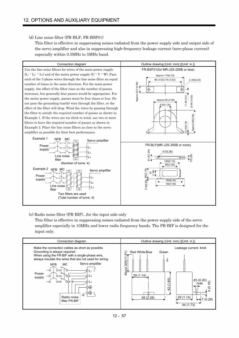
12 - 57
12. OPTIONS AND AUXILIARY EQUIPMENT
(d) Line noise filter (FR-BLF, FR-BSF01)This filter is effective in suppressing noises radiated from the power supply side and output side ofthe servo amplifier and also in suppressing high-frequency leakage current (zero-phase current)especially within 0.5MHz to 5MHz band.
Connection diagram Outline drawing [Unit: mm] ([Unit: in.])
FR-BSF01(for MR-J2S-200B or less)
95 0.5(3.74 0.02)
4.5(
0.18
)
Approx.110(4.33)
Appr
ox 2
2 .5
(0.8
9)
Appr
ox.6
5(2 .
56)
Approx.65 (2.56)
2- 5(0.20)
33(1.30) 11.2
5 0
.5
(0.4
5 0
.02)
Use the line noise filters for wires of the main power supply(L1 L2 L3) and of the motor power supply (U V W). Passeach of the 3-phase wires through the line noise filter an equalnumber of times in the same direction. For the main powersupply, the effect of the filter rises as the number of passesincreases, but generally four passes would be appropriate. Forthe motor power supply, passes must be four times or less. Donot pass the grounding (earth) wire through the filter, or theeffect of the filter will drop. Wind the wires by passing throughthe filter to satisfy the required number of passes as shown inExample 1. If the wires are too thick to wind, use two or morefilters to have the required number of passes as shown inExample 2. Place the line noise filters as close to the servoamplifier as possible for their best performance.
Example 2
Two filters are used (Total number of turns: 4)
Power supply
Servo amplifier
Line noise filter
NFB
L3
L1
L2
MC
Example 1
(Number of turns: 4)
Power supply
NFB
L1
L2
L3
Servo amplifier
Line noise filter
MC
FR-BLF(MR-J2S-350B or more)
160(6.30)180(7.09)
130(5.12)85(3.35)
80(3
.15)
2.3(
0.0 9
)
3 5
(1.3
8)
31.5
(1.2
4) 7(0.28)
7(0.
28)
(e) Radio noise filter (FR-BIF)...for the input side onlyThis filter is effective in suppressing noises radiated from the power supply side of the servoamplifier especially in 10MHz and lower radio frequency bands. The FR-BIF is designed for theinput only.
Connection diagram Outline drawing (Unit: mm) ([Unit: in.])
Make the connection cables as short as possible. Grounding is always required.When using the FR-BIF with a single-phase wire, always insulate the wires that are not used for wiring.
Servo amplifierNFB
L3
L2
L1
MC
Powersupply
Radio noise filter FR-BIF
Leakage current: 4mA
29 (1.14)
58 (2.28)
42 (1
.65)
4 (0
.16)
Red BlueWhite Green
44 (1.73)
29 (1.14) 7 (0.28)
hole
Abo
ut 3
00(1
1.81
)
5 (0.20)
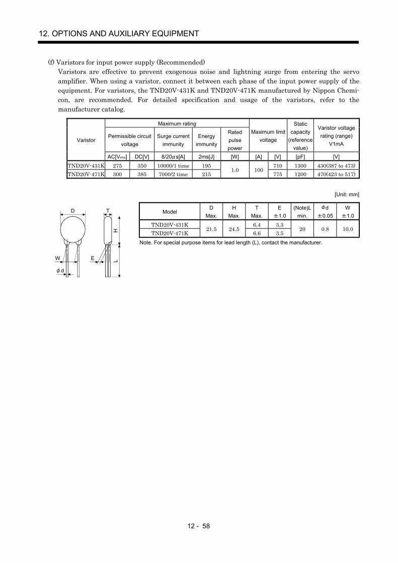
12 - 58
12. OPTIONS AND AUXILIARY EQUIPMENT
(f) Varistors for input power supply (Recommended)Varistors are effective to prevent exogenous noise and lightning surge from entering the servoamplifier. When using a varistor, connect it between each phase of the input power supply of theequipment. For varistors, the TND20V-431K and TND20V-471K manufactured by Nippon Chemi-con, are recommended. For detailed specification and usage of the varistors, refer to themanufacturer catalog.
Maximum rating
Permissible circuitvoltage
Surge currentimmunity
Energyimmunity
Ratedpulsepower
Maximum limitvoltage
Staticcapacity
(referencevalue)
Varistor voltagerating (range)
V1mAVaristor
AC[Vrms] DC[V] 8/20 s[A] 2ms[J] [W] [A] [V] [pF] [V]
TND20V-431K 275 350 10000/1 time 195 710 1300 430(387 to 473)TND20V-471K 300 385 7000/2 time 215
1.0 100775 1200 470(423 to 517)
[Unit: mm]
ModelD
Max.H
Max.T
Max.E1.0
(Note)Lmin.
d0.05
W1.0
TND20V-431K 6.4 3.3TND20V-471K
21.5 24.56.6 3.5
20 0.8 10.0
Note. For special purpose items for lead length (L), contact the manufacturer.
d
W E
H
D
L
T

12 - 59
12. OPTIONS AND AUXILIARY EQUIPMENT
12.2.8 Leakage current breaker
(1) Selection methodHigh-frequency chopper currents controlled by pulse width modulation flow in the AC servo circuits.Leakage currents containing harmonic contents are larger than those of the motor which is run with acommercial power supply.Select a leakage current breaker according to the following formula, and ground the servo amplifier,servo motor, etc. securely.Make the input and output cables as short as possible, and also make the grounding cable as long aspossible (about 30cm (11.8 in)) to minimize leakage currents.
Rated sensitivity current 10 {Ig1 Ign Iga K (Ig2 Igm)} [mA] ..........(12.1)
K: Constant considering the harmonic contentsLeakage current breaker
TypeMitsubishiproducts
K
Models provided withharmonic and surgereduction techniques
NV-SPNV-SWNV-CPNV-CWNV-HW
1
MServo amplifier
Noise filter
NV
Ig1 Ign Iga Ig2 Igm
Cable
Cable
General modelsBV-C1NFBNV-L
3
Ig1: Leakage current on the electric channel from the leakage current breaker to the input terminalsof the servo amplifier (Found from Fig. 12.1.)
Ig2: Leakage current on the electric channel from the output terminals of the servo amplifier to the servo motor (Found from Fig. 12.1.)
Ign: Leakage current when a filter is connected to the input side (4.4mA per one FR-BIF)Iga: Leakage current of the servo amplifier (Found from Table 12.5.)Igm: Leakage current of the servo motor (Found from Table 12.4.)
Table 12.4 Servo motor'sleakage currentexample (Igm)
Table 12.5 Servo amplifier'sleakage currentexample (Iga)
Servo motoroutput [kW]
Leakagecurrent [mA]
Servo amplifiercapacity [kW]
Leakage current[mA]
0.05 to 0.5 0.10.6 to 1.0 0.1
0.1 to 0.6 0.1
1.2 to 2.2 0.23 to 3.5 0.3
0.7 to 3.5 0.15
5 0.5 5 7 27 0.7 11 15 5.5
11 1.0 22 715 1.322 2.3 Table 12.6 Leakage circuit breaker selection example
Servo amplifierRated sensitivity
current of leakagecircuit breaker [mA]
MR-J2S-10B to MR-J2S-350BMR-J2S-10B1 to MR-J2S-40B1
15
MR-J2S-500B 30
120
100
80
60
40
20
02 3.5
5.58 1422 38 80 150
30 60 100
Fig. 12.1 Leakage current example (Ig1, Ig2) for CV cable run in metal conduit
Cable size[mm2]
[mA]
Leak
age
curr
ent
MR-J2S-700B 50MR-J2S-11KB to MR-J2S-22KB 100

12 - 60
12. OPTIONS AND AUXILIARY EQUIPMENT
(2) Selection exampleIndicated below is an example of selecting a leakage current breaker under the following conditions.
MServoamplifier MR-J2S-60B
Servo motor HC-MFS73
Ig1 Ig2Iga Igm
NV
2mm2 5m 2mm2 5m
Use a leakage current breaker designed for suppressing harmonics/surges.Find the terms of Equation (12.1) from the diagram.
Ig1 20 10005 0.1 [mA]
Ig2 20 10005 0.1 [mA]
Ign 0 (not used)
Iga 0.1 [mA]
Igm 0.1 [mA]
Insert these values in Equation (12.1).
Ig 10 {0.1 0 0.1 1 (0.1 0.1)}
4 [mA]
According to the result of calculation, use a leakage current breaker having the rated sensitivitycurrent (Ig) of 4[mA] or more. A leakage current breaker having Ig of 15[mA] is used with the NV-SP/CP/SW/CW/HW series.

12 - 61
12. OPTIONS AND AUXILIARY EQUIPMENT
12.2.9 EMC filter
For compliance with the EMC directive of the EN standard, it is recommended to use the following filter.Some EMC filters are large in leakage current.
(1) Combination with the servo amplifier
Recommended filterServo amplifier
Model Leakage current [mA]Mass
[kg]([Ib])
MR-J2S-10B to MR-J2S-100BMR-J2S-10B1 to MR-J2S-40B1
SF1252 38 0.75(1.65)
MR-J2S-200B MR-J2S-350B SF1253 57 1.37(3.02)MR-J2S-500B (Note) HF3040A-TM 1.5 6.0(13.23)MR-J2S-700B (Note) HF3050A-TM 1.5 6.7(14.77)MR-J2S-11KB (Note) HF3060A-TMA 3.0 10.0(22.05)MR-J2S-15KB (Note) HF3080A-TMA 3.0 13.0(28.66)MR-J2S-22KB (Note) HF3100A-TMA 3.0 14.5(31.97)
Note. Soshin Electric. A surge protector is separately required to use any of these EMC filters. (Refer to the EMC InstallationGuidelines.)
(2) Connection example
L1
L2
L3
L11
L21
L1
L2
L3
L1
L2
L3
LINE LOAD
(Note 2)
NFB MC
(Note 1)Power supply
EMC filter(SF1252, SF1253) Servo amplifier
L1
L2
L3
L11
L21
Servo amplifier
1
2
3
4
5
6
E
MC
Surge protector 1(RAV-781BYZ-2)(OKAYA Electric Industries
Co., Ltd.)
Surge protector 2(RAV-781BXZ-4)(OKAYA Electric Industries Co., Ltd.)
NFB
(Note 1)Power supply
1
2
3
1 2 3
EMC filter(SOSHIN Electric Co., Ltd)
Note 1. For 1-phase 230V power supply, connect the power supply to L1, L2 and leave L3 open. There is no L3 for 1-phase 100 to 120Vpower supply. Refer to section 1.3 for the power supply specification.
2. Connect when the power supply has earth.
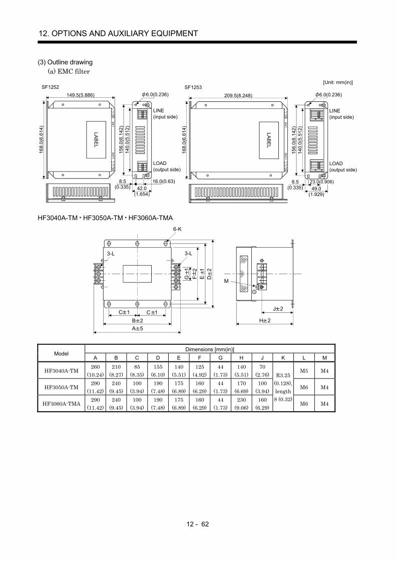
12 - 62
12. OPTIONS AND AUXILIARY EQUIPMENT
(3) Outline drawing(a) EMC filter
23.0(0.906)
LABEL
LIN
ELO
AD
168.
0(6.
614)
L1'L2'L3'
L1L2L3
149.5(5.886)
LINE(input side)
LOAD(output side)
140.
0(5.
512)
156.
0(6.
142)
16.0(0.63)42.0
8.5
SF1252
LABEL
LIN
ELO
AD
168.
0(6.
614)
L1'L2'L3'
L1L2L3
209.5(8.248)
LINE(input side)
LOAD(output side)
140.
0(5.
512)
156.
0(6.
142)
49.08.5
SF1253[Unit: mm(in)]
(0.335)(1.654)
(0.335)(1.929)
6.0(0.236) 6.0(0.236)
HF3040A-TM HF3050A-TM HF3060A-TMA
H 2
J 2
G
1F
2E
1D
2
3-L
6-K
3-L
M
C 1B 2A 5
C 1
Dimensions [mm(in)]Model
A B C D E F G H J K L M
HF3040A-TM260
(10.24)210
(8.27)85
(8.35)155
(6.10)140
(5.51)125
(4.92)44
(1.73)140
(5.51)70
(2.76)M5 M4
HF3050A-TM290
(11.42)240
(9.45)100
(3.94)190
(7.48)175
(6.89)160
(6.29)44
(1.73)170
(6.69)100
(3.94)M6 M4
HF3060A-TMA290
(11.42)240
(9.45)100
(3.94)190
(7.48)175
(6.89)160
(6.29)44
(1.73)230
(9.06)160
(6.29)
R3.25(0.128),length8 (0.32)
M6 M4
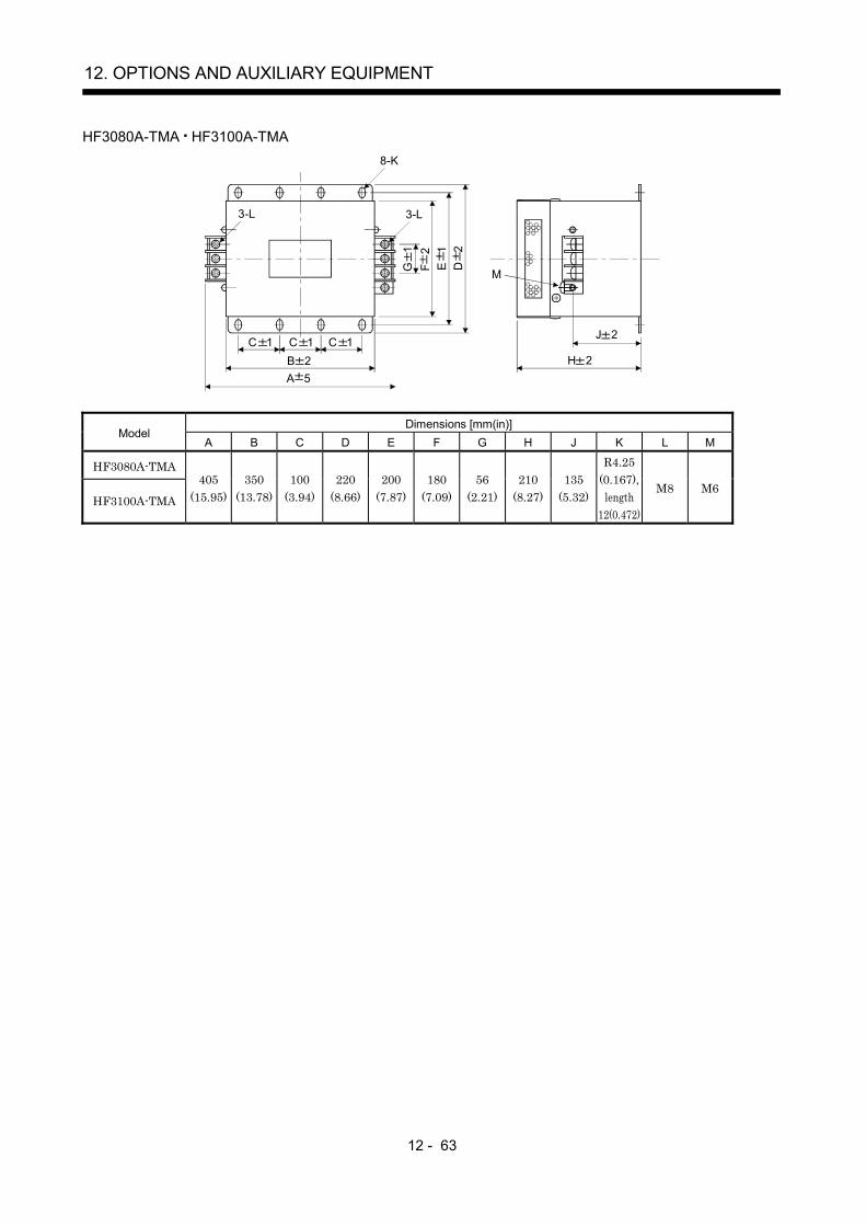
12 - 63
12. OPTIONS AND AUXILIARY EQUIPMENT
HF3080A-TMA HF3100A-TMA
H 2
J 2
G
1F
2E
1
D
2
3-L
8-K
3-L
M
C 1B 2A 5
C 1 C 1
Dimensions [mm(in)]Model
A B C D E F G H J K L M
HF3080A-TMA
HF3100A-TMA
405(15.95)
350(13.78)
100(3.94)
220(8.66)
200(7.87)
180(7.09)
56(2.21)
210(8.27)
135(5.32)
R4.25(0.167),
length12(0.472)
M8 M6

12 - 64
12. OPTIONS AND AUXILIARY EQUIPMENT
(b) Surge protectorRAV-781BYZ-2
4.5
0.51 32
41 1.0
28.5
1.
028
1.
0
4.2 0.2
200
30 0 UL-1015AWG16
5.5
1
11
1
[Unit: mm]
Black1) 2) 3)
Black Black
RAV-781BXZ-4
1 32
UL-1015AWG16
4.2 0.2 5.5
1
11
128
.5
1.0
200
30 028
1.
0
41 1.0
4.5
0.5
[Unit: mm]
1) 2) 3) 4)
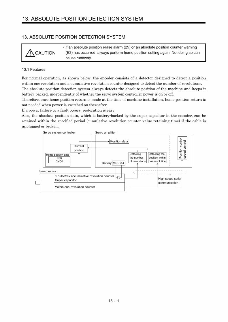
13 - 1
13. ABSOLUTE POSITION DETECTION SYSTEM
13. ABSOLUTE POSITION DETECTION SYSTEM
CAUTIONIf an absolute position erase alarm (25) or an absolute position counter warning(E3) has occurred, always perform home position setting again. Not doing so cancause runaway.
13.1 Features
For normal operation, as shown below, the encoder consists of a detector designed to detect a positionwithin one revolution and a cumulative revolution counter designed to detect the number of revolutions.The absolute position detection system always detects the absolute position of the machine and keeps itbattery-backed, independently of whether the servo system controller power is on or off.Therefore, once home position return is made at the time of machine installation, home position return isnot needed when power is switched on thereafter.If a power failure or a fault occurs, restoration is easy.Also, the absolute position data, which is battery-backed by the super capacitor in the encoder, can beretained within the specified period (cumulative revolution counter value retaining time) if the cable isunplugged or broken.
Servo system controller
Currentposition
Home position dataLS0
CYC0
Servo amplifier
Position data
MR-BATBattery
Detectingthe numberof revolutions
Detecting theposition withinone revolution
Posi
tion
cont
rol
spee
d co
ntro
l
High speed serialcommunication
Servo motor1 pulse/rev accumulative revolution counter Super capacitor
Within one-revolution counter
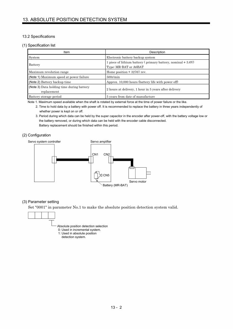
13 - 2
13. ABSOLUTE POSITION DETECTION SYSTEM
13.2 Specifications
(1) Specification list
Item Description
System Electronic battery backup system
Battery1 piece of lithium battery ( primary battery, nominal 3.6V)Type: MR-BAT or A6BAT
Maximum revolution range Home position 32767 rev.(Note 1) Maximum speed at power failure 500r/min(Note 2) Battery backup time Approx. 10,000 hours (battery life with power off)(Note 3) Data holding time during battery
replacement2 hours at delivery, 1 hour in 5 years after delivery
Battery storage period 5 years from date of manufactureNote 1. Maximum speed available when the shaft is rotated by external force at the time of power failure or the like. 2. Time to hold data by a battery with power off. It is recommended to replace the battery in three years independently of
whether power is kept on or off. 3. Period during which data can be held by the super capacitor in the encoder after power-off, with the battery voltage low or
the battery removed, or during which data can be held with the encoder cable disconnected.Battery replacement should be finished within this period.
(2) Configuration
CN1 CN2
CN5
Servo system controller Servo amplifier
Battery (MR-BAT)Servo motor
(3) Parameter settingSet "0001" in parameter No.1 to make the absolute position detection system valid.
Absolute position detection selection 0: Used in incremental system. 1: Used in absolute position detection system.

13 - 3
13. ABSOLUTE POSITION DETECTION SYSTEM
13.3 Battery installation procedure
WARNING
Before installing a battery, turn off the main circuit power while keeping the controlcircuit power on. Wait for 15 minutes or more until the charge lamp turns off. Then,confirm that the voltage between P and N is safe with a voltage tester and others.Otherwise, an electric shock may occur. In addition, always confirm from the frontof the servo amplifier whether the charge lamp is off or not.
POINTThe internal circuits of the servo amplifier may be damaged by staticelectricity. Always take the following precautions.
Ground human body and work bench.Do not touch the conductive areas, such as connector pins and electricalparts, directly by hand.
1) Open the operation window. (When the model used is the MR-J2S-200B MR-J2S-350B, also removethe front cover.)
2) Install the battery in the battery holder.
3) Install the battery connector into CON1 until it clicks.
Battery connector
Battery
Operation window
CON1
Battery holderFor MR-J2S-200B or less
CON1
Battery connector
Battery
Battery holder
Battery connector
CON1
Battery holder Battery
For MR-J2S-500B MR-J2S-700B
For MR-J2S-200B MR-J2S-350B
For MR-J2S-11KB or more
Battery holder
CON1
Battery
Battery connector
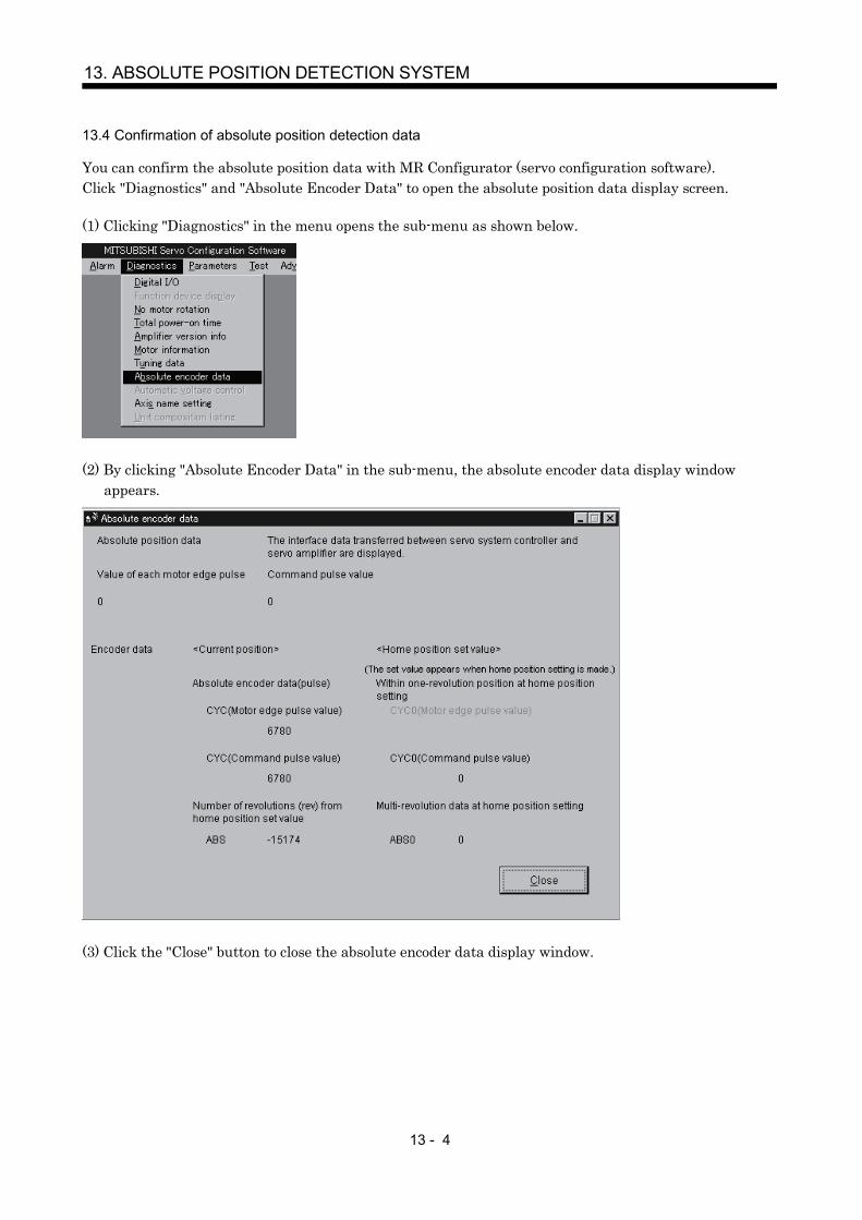
13 - 4
13. ABSOLUTE POSITION DETECTION SYSTEM
13.4 Confirmation of absolute position detection data
You can confirm the absolute position data with MR Configurator (servo configuration software).Click "Diagnostics" and "Absolute Encoder Data" to open the absolute position data display screen.
(1) Clicking "Diagnostics" in the menu opens the sub-menu as shown below.
(2) By clicking "Absolute Encoder Data" in the sub-menu, the absolute encoder data display windowappears.
(3) Click the "Close" button to close the absolute encoder data display window.

App - 1
APPENDIX
App 1. Combination of servo amplifier and servo motor
The servo amplifier software versions compatible with the servo motors are indicated in the parentheses.The servo amplifiers whose software versions are not indicated can be used regardless of the versions.
Servo motorServo amplifier
(Software version)Servo motor
Servo amplifier(Software version)
HC-RFS103 MR-J2S-200BHC-KFS053
MR-J2S-10BMR-J2S-10B1 HC-RFS153 MR-J2S-200B
HC-RFS203 MR-J2S-350B (Version B0 or later)HC-KFS13
MR-J2S-10BMR-J2S-10B1 HC-RFS353 MR-J2S-500B (Version B0 or later)
HC-RFS503 MR-J2S-500B (Version B0 or later)HC-KFS23
MR-J2S-20BMR-J2S-20B1 HC-UFS72 MR-J2S-70B
HC-UFS152 MR-J2S-200BHC-KFS43
MR-J2S-40BMR-J2S-40B1 HC-UFS202 MR-J2S-350B (Version B0 or later)
HC-KFS73 MR-J2S-70B (Version A3 or later) HC-UFS352 MR-J2S-500B (Version B0 or later)HC-UFS502 MR-J2S-500B (Version B0 or later)
HC-MFS053MR-J2S-10BMR-J2S-10B1
HC-UFS13MR-J2S-10BMR-J2S-10B1
HC-MFS13MR-J2S-10BMR-J2S-10B1
HC-UFS23MR-J2S-20BMR-J2S-20B1
HC-MFS23MR-J2S-20BMR-J2S-20B1
HC-UFS43MR-J2S-40BMR-J2S-40B1
HC-MFS43MR-J2S-40BMR-J2S-40B1 HC-UFS73 MR-J2S-70B
HC-MFS73 MR-J2S-70B HC-LFS52 MR-J2S-60B (Version B3 or later)HC-SFS81 MR-J2S-100B HC-LFS102 MR-J2S-100B (Version B3 or later)HC-SFS121 MR-J2S-200B HC-LFS152 MR-J2S-200B (Version B3 or later)HC-SFS201 MR-J2S-200B HC-LFS202 MR-J2S-350B (Version B3 or later)HC-SFS301 MR-J2S-350B HC-LFS302 MR-J2S-500B (Version B3 or later)HC-SFS52 MR-J2S-60B HA-LFS801 MR-J2S-11KB (Version A3 or later)HC-SFS102 MR-J2S-100B HA-LFS12K1 MR-J2S-11KB (Version A3 or later)HC-SFS152 MR-J2S-200B HA-LFS15K1 MR-J2S-15KB (Version A3 or later)HC-SFS202 MR-J2S-200B HA-LFS20K1 MR-J2S-22KB (Version A3 or later)HC-SFS352 MR-J2S-350B HA-LFS25K1 MR-J2S-22KB (Version A3 or later)HC-SFS502 MR-J2S-500B (Version B0 or later) HA-LFS11K1M MR-J2S-11KB (Version A4 or later)HC-SFS702 MR-J2S-700B (Version B0 or later) HA-LFS15K1M MR-J2S-15KB (Version A3 or later)HC-SFS53 MR-J2S-60B HA-LFS502 MR-J2S-500B (Version B0 or later)HC-SFS103 MR-J2S-100B HA-LFS702 MR-J2S-700B (Version B0 or later)HC-SFS153 MR-J2S-200B HA-LFS11K2 MR-J2S-11KB (Version A3 or later)HC-SFS203 MR-J2S-200B HA-LFS15K2 MR-J2S-15KB (Version A3 or later)HC-SFS353 MR-J2S-350B HA-LFS22K2 MR-J2S-22KB (Version A3 or later)

App - 2
APPENDIX
App 2. Change of connector sets to the RoHS compatible products
Connector sets (options) in the following table are changed to the RoHS compatible products afterSeptember, 2006 shipment.Please accept that the current products might be mixed with RoHS compatible products based onavailability.
Model Current Product RoHS Compatible Product
MR-J2CNMMR-J2CN1
Amplifier connector (3M or equivalent)10120-3000VE (connector)
Amplifier connector (3M or equivalent)10120-3000PE (connector)
MR-J2CNS Amplifier connector (3M or equivalent)10120-3000VE (connector)Encoder connector (DDK)MS3057-12A (Cable clump)MS3106B20-29S (Straight plug)
Amplifier connector (3M or equivalent)10120-3000PE (connector)Encoder connector (DDK)D/MS3057-12A (Cable clump)D/MS3106B20-29S (Straight plug)
MR-ENCBL M-HMR-ENCNS
Amplifier connector (3M or equivalent)10120-3000VE (connector)MS3106A20-29S (D190) (Plug, DDK)CE3057-12A-3 (D265) (Cable clump, DDK)CE02-20BS-S (Back shell, DDK)
Amplifier connector (3M or equivalent)10120-3000PE (connector)D/MS3106A20-29S (D190) (Plug, DDK)CE3057-12A-3-D (Cable clump, DDK)CE02-20BS-S-D (Back shell, DDK)
MR-PWCNS1 Power supply connector (DDK)CE05-6A22-23SD-B-BSS (Connector and backshell)CE3057-12A-2 (D265) (Cable clump)
Power supply connector (DDK)CE05-6A22-23SD-D-BSS (Connector and backshell)CE3057-12A-2-D (Cable clump)
MR-PWCNS2 Power supply connector (DDK)CE05-6A24-24SD-B-BSS (Connector and backshell)CE3057-16A-2 (D265) (Cable clump)
Power supply connector (DDK)CE05-6A24-10SD-B-BSS (Connector and backshell)CE3057-16A-2-D (Cable clump)
MR-PWCNS3 Power supply connector (DDK)CE05-6A32-17SD-B-BSS (Connector and backshell)CE3057-20A-1 (D265) (Cable clump)
Power supply connector (DDK)CE05-6A32-17SD-D-BSS (Connector and backshell)CE3057-20A-1-D (Cable clump)
MR-BKCN Electromagnetic brake connectorMS3106A10SL-4S (D190) (Plug, DDK)
Electromagnetic brake connectorD/MS3106A10SL-4S (D190) (Plug, DDK)
MR-J2CN1-A Controller connector (Honda Tsushin Industry)PCR-S20FS (Connector)Amplifier connector (3M or equivalent)10120-3000VE (Connector)
Controller connector (Honda Tsushin Industry)PCR-S20FS (Connector)Amplifier connector (3M or equivalent)10120-3000PE (Connector)
Note. RoHS compatible 36210-0100FD may be packed with current connector sets.
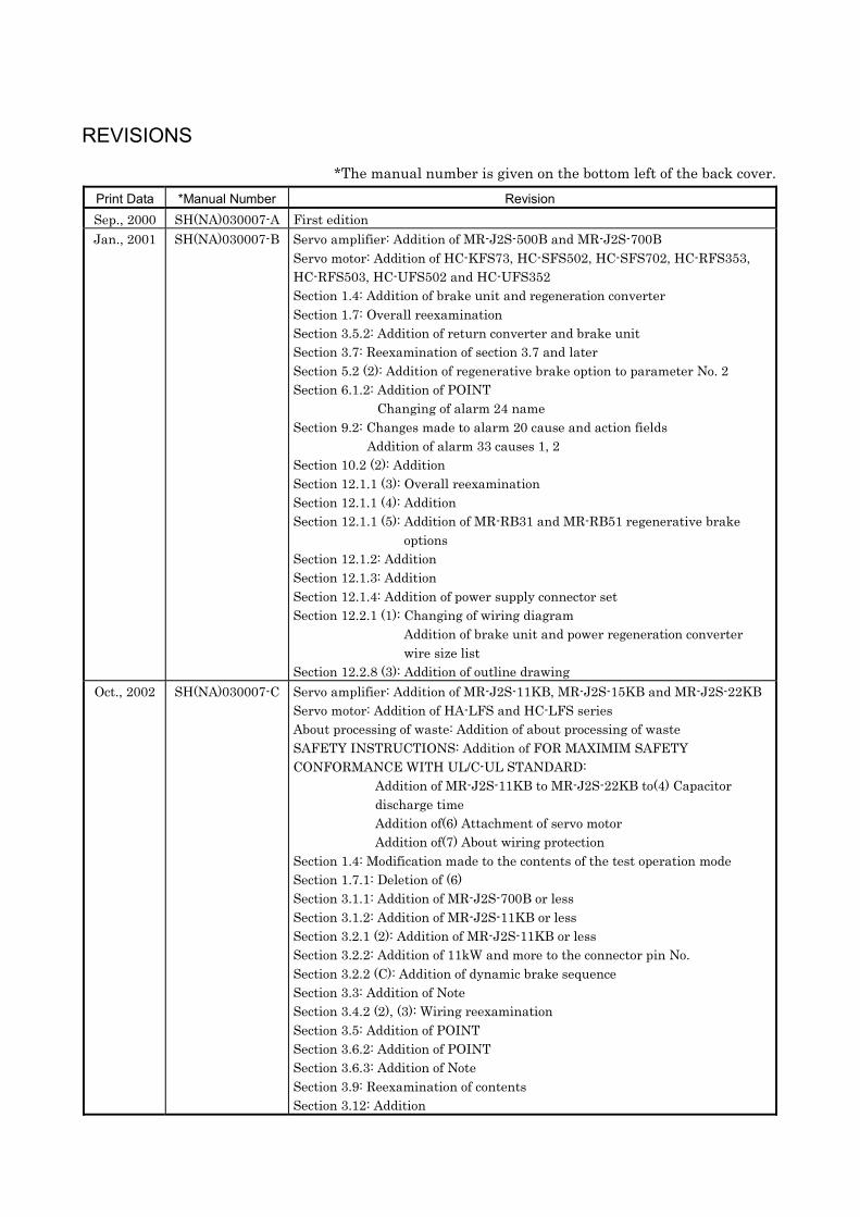
REVISIONS
*The manual number is given on the bottom left of the back cover.Print Data *Manual Number RevisionSep., 2000 SH(NA)030007-A First editionJan., 2001 SH(NA)030007-B Servo amplifier: Addition of MR-J2S-500B and MR-J2S-700B
Servo motor: Addition of HC-KFS73, HC-SFS502, HC-SFS702, HC-RFS353,HC-RFS503, HC-UFS502 and HC-UFS352Section 1.4: Addition of brake unit and regeneration converterSection 1.7: Overall reexaminationSection 3.5.2: Addition of return converter and brake unitSection 3.7: Reexamination of section 3.7 and laterSection 5.2 (2): Addition of regenerative brake option to parameter No. 2Section 6.1.2: Addition of POINT
Changing of alarm 24 nameSection 9.2: Changes made to alarm 20 cause and action fields
Addition of alarm 33 causes 1, 2Section 10.2 (2): AdditionSection 12.1.1 (3): Overall reexaminationSection 12.1.1 (4): AdditionSection 12.1.1 (5): Addition of MR-RB31 and MR-RB51 regenerative brake
optionsSection 12.1.2: AdditionSection 12.1.3: AdditionSection 12.1.4: Addition of power supply connector setSection 12.2.1 (1): Changing of wiring diagram
Addition of brake unit and power regeneration converterwire size list
Section 12.2.8 (3): Addition of outline drawingOct., 2002 SH(NA)030007-C Servo amplifier: Addition of MR-J2S-11KB, MR-J2S-15KB and MR-J2S-22KB
Servo motor: Addition of HA-LFS and HC-LFS seriesAbout processing of waste: Addition of about processing of wasteSAFETY INSTRUCTIONS: Addition of FOR MAXIMIM SAFETYCONFORMANCE WITH UL/C-UL STANDARD:
Addition of MR-J2S-11KB to MR-J2S-22KB to(4) Capacitordischarge timeAddition of(6) Attachment of servo motorAddition of(7) About wiring protection
Section 1.4: Modification made to the contents of the test operation modeSection 1.7.1: Deletion of (6)Section 3.1.1: Addition of MR-J2S-700B or lessSection 3.1.2: Addition of MR-J2S-11KB or lessSection 3.2.1 (2): Addition of MR-J2S-11KB or lessSection 3.2.2: Addition of 11kW and more to the connector pin No.Section 3.2.2 (C): Addition of dynamic brake sequenceSection 3.3: Addition of NoteSection 3.4.2 (2), (3): Wiring reexaminationSection 3.5: Addition of POINTSection 3.6.2: Addition of POINTSection 3.6.3: Addition of NoteSection 3.9: Reexamination of contentsSection 3.12: Addition

Print Data *Manual Number RevisionOct., 2002 SH(NA)030007-C Section 3.12.2: Addition of power factor improving DC reactor
Section 4.3 (2): Addition of initialization completionSection 5.2 (2): Addition of external dynamic brake selection to parameter No. 2
Renaming of parameter Nos. 3 to 5Reexamination of parameter No. 19 contents
Section 9.1: Addition of Note to alarm 30Section 9.2: Addition of occurrence factor 4 to alarm 16
Changing of occurrence factor and checking method of alarm 50Changing of occurrence factor and checking method of alarm 51
Section 10.1 (7), (8): Addition of MR-J2S-11KB, 15KB and 22KBSection 10.2 (a): Addition of connectors and shell kitsSection 11.1 (4): AdditionSection 11.3: Reexamination of HC-KFS series dynamic brake time constants
Addition of HA-LFS seriesSection 12.1.1 (3): Addition of sentencesSection 12.1.1 (4) (a): Reexamination of contentsSection 12.1.1 (4) (b): Reexamination of contentsSection 12.1.1 (4) (c): Addition of sentencesSection 12.1.1 (4) (d): AdditionSection 12.1.1 (5) (e): AdditionSection 12.1.2 (1), (3): Addition of FR-BU-55K brake unitSection 12.1.2 (3) (a), (b): Addition of FR-BR-55K resistor unitSection 12.1.3 (1), (3), (4): Addition of FR-RC-55K power regeneration converterSection 12.1.4: Addition; reexamination of subsequent sectionsSection 12.1.5: Addition of HA-LFS series wiring
Addition of connector sets and monitor cablesSection 12.1.6: Addition of POINTSection 12.1.7 (1): Reexamination of contentsSection 12.1.7 (2) (a): Reexamination of contentsSection 12.2.1 (1): Addition of cooling fan wiring
Addition of FR-RC-30K and FR-RC-50KSection 12.2.1 (2): Reexamination of optional cable tableSection 12.2.4: Addition of power factor improving DC reactor; reexamination
of subsequent sectionsSection 12.2.5: Changing of interface name into digital input signalsSection 12.2.8 (1): Reexamination of our leakage current breaker productsSection 12.2.9 (3): Addition of outline drawingSection 13.3: Addition of MR-J2S-11KB and moreSection 13.4: Screen change
May., 2003 SH(NA)030007-D COMPLIANCE WITH EC DIRECTIVES 2 (6): Addition of (6)CONFORMANCE WITH UL/C-UL STANDARD: Addition of (2) Air volume
(2.8m3/min)Section 1.3: Inrush current additionSection 3.1.1: Reexamination of table in NoteSection 3.1.2: Reexamination of table in NoteSection 3.6.3: Addition of power supply connector signal arrangement CE05-
2A32-17PD-BSection 3.12.3: Change of terminal box inside of HA-LFS11K2Section 5.2 (1): Reexamination of alarm 8 initial valueSection 5.2 (2): Addition of "Use of built-in regenerative brake resistor" to
parameter No. 2Section 5.2 (2): Reexamination of alarm 8 initial value

Print Data *Manual Number RevisionMay., 2003 SH(NA)030007-D Section 9.1: Partial sentence change
Section 9.2: Partial POINT sentence reexaminationSection 9.2: Reexamination of alarm 12, 13 definitions
Reexamination of alarm 15 definitionAddition of alarm 37 occurrence factor and corrective actionAddition of During rotation: 2.5s or more to alarm 51
Section 10.2 (2) (a): Addition of model PCRSection 11.3: Reexamination of explanation of teSection 11.5: Addition of inrush currents at power-on of main circuit and
control circuitSection 12.1.2: Partial sentence additionSection 12.1.3: Partial sentence additionSection 12.1.3 (2): Addition of NoteSection 12.1.4 (2): Correction of connection example
Addition of NoteSection 12.1.5: Addition of bus cable connected to motion controllerSection 12.1.5 (4): Reexamination/addition of contentsSection 12.1.6: POINT sentence changeSection 12.2.1 (1): Correction of error in writing of recommended wireMR-J2S-22KB wire sizeSection 12.2.1 (2): Addition of bus cable Q172J2BCBL M/Q173J2B CBL M
Jan., 2004 SH(NA)030007-E Safety Instructions: Overall reexaminationSection 1.5 (2): Partial additionSection 1.6: Table reexaminationSection 1.8 (3): Note additionSection 1.8 (4): Note additionSection 3.1.1: Note 15. reexaminationSection 3.1.2: Note 15. reexaminationSection 4.2: Partial reexamination/addition of CAUTION sentenceSection 5.2: Partial addition of POINT sentenceSection 5.2 (1): Addition of Note 3Section 5.2 (2): Partial addition of parameter No. 2
Note addition of parameter No. 31Section 5.4.2: (10) deletionSection 9.2: Display 32 item addition, Partial reexamination/Note addition of
display 52Section 10.1: Overall reexaminationSection 11.2: Table changeSection 11.3: Partial text additionSection 12.1.1 (3): Partial text deletionSection 12.1.1 (4): Partial text changeSection 12.1.1 (5): Overall reexaminationSection 12.1.4 (2): Addition of Note 2Section 12.1.7: POINT additionSection 12.1.8 (1)(a): Partial table reexaminationSection 12.1.9 (2): Partial figure reexaminationSection 12.1.10: AdditionSection 12.2.9 (3): Partial reexaminationAppendix: AdditionWARNING of “To prevent electric shock”: Correction of “10 minutes” to “15
minutes”Correction of axis switch model to “SW1”
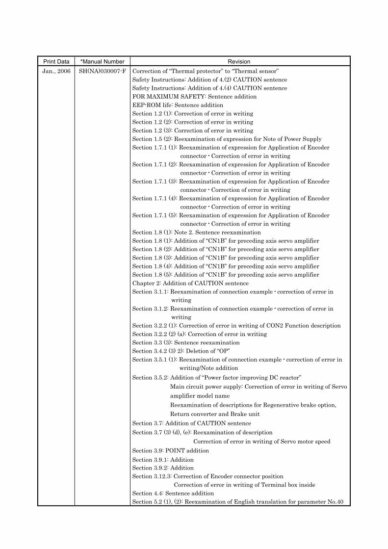
Print Data *Manual Number RevisionJan., 2006 SH(NA)030007-F Correction of “Thermal protector” to “Thermal sensor”
Safety Instructions: Addition of 4.(2) CAUTION sentenceSafety Instructions: Addition of 4.(4) CAUTION sentenceFOR MAXIMUM SAFETY: Sentence additionEEP-ROM life: Sentence additionSection 1.2 (1): Correction of error in writingSection 1.2 (2): Correction of error in writingSection 1.2 (3): Correction of error in writingSection 1.5 (2): Reexamination of expression for Note of Power SupplySection 1.7.1 (1): Reexamination of expression for Application of Encoder
connector Correction of error in writingSection 1.7.1 (2): Reexamination of expression for Application of Encoder
connector Correction of error in writingSection 1.7.1 (3): Reexamination of expression for Application of Encoder
connector Correction of error in writingSection 1.7.1 (4): Reexamination of expression for Application of Encoder
connector Correction of error in writingSection 1.7.1 (5): Reexamination of expression for Application of Encoder
connector Correction of error in writingSection 1.8 (1): Note 2. Sentence reexaminationSection 1.8 (1): Addition of “CN1B” for preceding axis servo amplifierSection 1.8 (2): Addition of “CN1B” for preceding axis servo amplifierSection 1.8 (3): Addition of “CN1B” for preceding axis servo amplifierSection 1.8 (4): Addition of “CN1B” for preceding axis servo amplifierSection 1.8 (5): Addition of “CN1B” for preceding axis servo amplifierChapter 2: Addition of CAUTION sentenceSection 3.1.1: Reexamination of connection example correction of error in
writingSection 3.1.2: Reexamination of connection example correction of error in
writingSection 3.2.2 (1): Correction of error in writing of CON2 Function descriptionSection 3.2.2 (2) (a): Correction of error in writingSection 3.3 (3): Sentence reexaminationSection 3.4.2 (3) 2): Deletion of “OP”Section 3.5.1 (1): Reexamination of connection example correction of error in
writing/Note additionSection 3.5.2: Addition of “Power factor improving DC reactor”
Main circuit power supply: Correction of error in writing of Servoamplifier model nameReexamination of descriptions for Regenerative brake option,Return converter and Brake unit
Section 3.7: Addition of CAUTION sentenceSection 3.7 (3) (d), (e): Reexamination of description
Correction of error in writing of Servo motor speedSection 3.9: POINT additionSection 3.9.1: AdditionSection 3.9.2: AdditionSection 3.12.3: Correction of Encoder connector position
Correction of error in writing of Terminal box insideSection 4.4: Sentence additionSection 5.2 (1), (2): Reexamination of English translation for parameter No.40
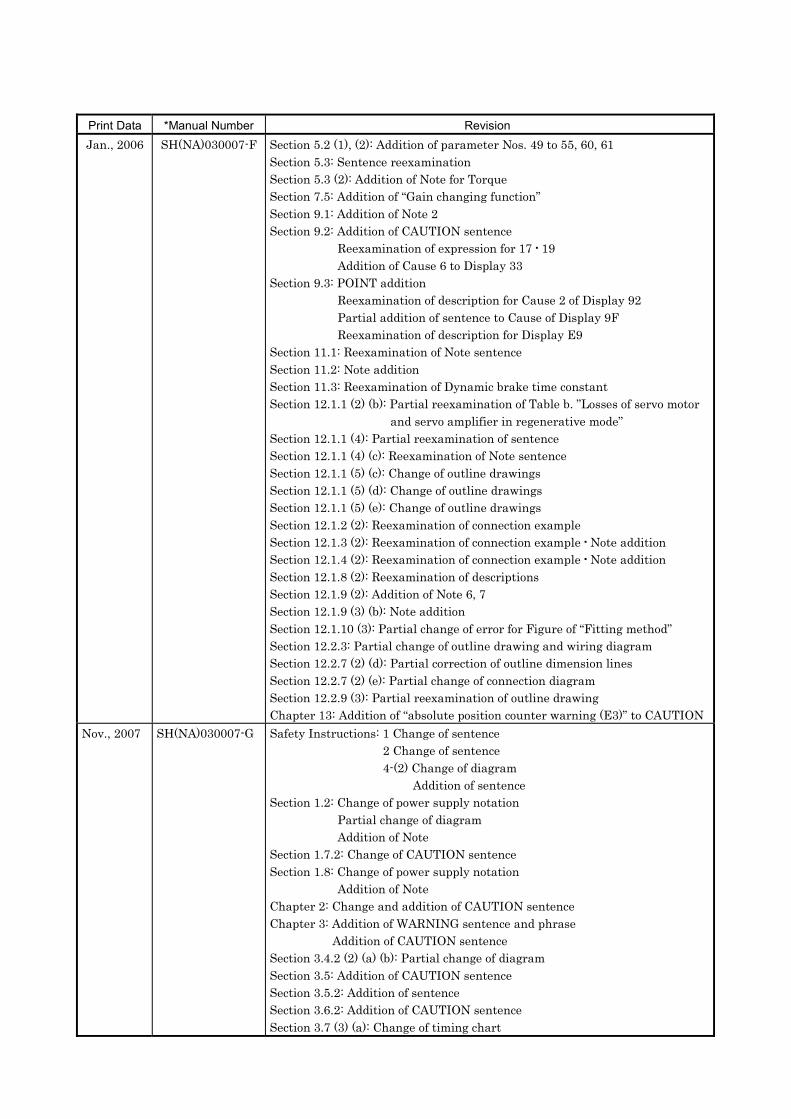
Print Data *Manual Number RevisionJan., 2006 SH(NA)030007-F Section 5.2 (1), (2): Addition of parameter Nos. 49 to 55, 60, 61
Section 5.3: Sentence reexaminationSection 5.3 (2): Addition of Note for TorqueSection 7.5: Addition of “Gain changing function”Section 9.1: Addition of Note 2Section 9.2: Addition of CAUTION sentence
Reexamination of expression for 17 19Addition of Cause 6 to Display 33
Section 9.3: POINT additionReexamination of description for Cause 2 of Display 92Partial addition of sentence to Cause of Display 9FReexamination of description for Display E9
Section 11.1: Reexamination of Note sentenceSection 11.2: Note additionSection 11.3: Reexamination of Dynamic brake time constantSection 12.1.1 (2) (b): Partial reexamination of Table b. ”Losses of servo motor
and servo amplifier in regenerative mode”Section 12.1.1 (4): Partial reexamination of sentenceSection 12.1.1 (4) (c): Reexamination of Note sentenceSection 12.1.1 (5) (c): Change of outline drawingsSection 12.1.1 (5) (d): Change of outline drawingsSection 12.1.1 (5) (e): Change of outline drawingsSection 12.1.2 (2): Reexamination of connection exampleSection 12.1.3 (2): Reexamination of connection example Note additionSection 12.1.4 (2): Reexamination of connection example Note additionSection 12.1.8 (2): Reexamination of descriptionsSection 12.1.9 (2): Addition of Note 6, 7Section 12.1.9 (3) (b): Note additionSection 12.1.10 (3): Partial change of error for Figure of “Fitting method”Section 12.2.3: Partial change of outline drawing and wiring diagramSection 12.2.7 (2) (d): Partial correction of outline dimension linesSection 12.2.7 (2) (e): Partial change of connection diagramSection 12.2.9 (3): Partial reexamination of outline drawingChapter 13: Addition of “absolute position counter warning (E3)” to CAUTION
Nov., 2007 SH(NA)030007-G Safety Instructions: 1 Change of sentence2 Change of sentence4-(2) Change of diagram
Addition of sentenceSection 1.2: Change of power supply notation
Partial change of diagramAddition of Note
Section 1.7.2: Change of CAUTION sentenceSection 1.8: Change of power supply notation
Addition of NoteChapter 2: Change and addition of CAUTION sentenceChapter 3: Addition of WARNING sentence and phrase
Addition of CAUTION sentenceSection 3.4.2 (2) (a) (b): Partial change of diagramSection 3.5: Addition of CAUTION sentenceSection 3.5.2: Addition of sentenceSection 3.6.2: Addition of CAUTION sentenceSection 3.7 (3) (a): Change of timing chart

Print Data *Manual Number RevisionNov., 2007 SH(NA)030007-G Section 3.8: Change of power supply notation
Section 3.12: Addition and change of CAUTION sentenceSection 3.12.1: Addition of Note sentenceSection 5.1: Addition of item and change of parameter No. in tableSection 5.2 (1): Correction of error in writing of initial value for parameter
No.17Correction of error in writing of name for parameter No.52Correction of error in writing of name for parameter No.53Correction of error in writing of name for parameter No.54Correction of error in writing of name for parameter No.55
Section 5.2 (2): Correction of error in writing of name for parameter No.14Correction of error in writing of name for parameter No.15Correction of error in writing of name for parameter No.16Correction of error in writing of initial value for parameterNo.18Correction of error in writing of initial value for parameterNo.21Addition and partial change of expansion parameter No.40Correction of error in writing of name for parameter No.52
Section 6.4 (2): Change of operation explanation for step 5Chapter 8: Change of WARNING sentenceSection 9.2: Addition of item for display 20
Correction of error in writing of name for display 30Addition of sentence for display 32Addition of Cause 9 to Display 33Change of definition for Display 55
Section 10.1: Partial change and addition of phraseSection 10.2: Change to RoHS compatible connectorsSection 11.3: Addition of title and partial change of sentenceChapter 12: Change of WARNING sentenceSection 12.1.1 (2) (b): Partial change of energy formulaSection 12.1.1 (3): Partial change of notationSection 12.1.1 (4): Change of cooling fan specification notationSection 12.1.1 (5) (b): Change of outline drawingSection 12.1.1 (5) (c): Change of outline drawingSection 12.1.2: Significant change of contentsSection 12.1.4: Addition of POINT sentence
Change of power supply notation in diagramAddition of Note
Section 12.1.5: Change to RoHS compatible connectors and cablesSection 12.1.8 (2) (a): Change of personal computer descriptionSection 12.1.9 (2): Change of power supply notation in diagram
Addition of NoteSection 12.2.1: Change of crimping terminal of “b” in table 12.2Section 12.2.7 (2) (b): Addition of sentence for varistor recommendationSection 12.2.7 (2) (d): Change of sentence in connection diagram
Partial change of outline drawingSection 12.2.7 (2) (f): Addition of input power varistor (recommended)Section 12.2.9 (2): Addition of diagramSection 12.2.9 (3) (b): Addition of surge protectorSection 13.3: Change of WARNING sentenceApp.2: Addition of List of RoHS Compatible Product

J2-Su
per S
eriesM
R-J2S
- B S
ervo A
mp
lifier Instru
ction
Man
ual
SH (NA) 030007-G (0711) MEE Printed in Japan Specifications subject to change without notice.This Instruction Manual uses recycled paper.
MODEL
MODELCODE 1CW502
MR-J2S-B GIJUTU SIRYOU
G
General-Purpose AC Servo
MODEL
MR-J2S- BSERVO AMPLIFIERINSTRUCTION MANUAL
SSCNET Compatible
J2-Super Series
GHEAD OFFICE : TOKYO BLDG MARUNOUCHI TOKYO 100-8310


![400VAC Compatible MR-J2S- A4/B4 - Mitsubishi Electric€¦ · MR-J2S- A4/B4 SERVO AMPLIFIER SUPPLEMENTARY INSTRUCTION MANUAL ... 32 to 104 (non-freezing) [ ] 20 to 65 (non-freezing)](https://img.pdfslide.us/doc/110x75/5b069b237f8b9ae9628d4cfe/400vac-compatible-mr-j2s-a4b4-mitsubishi-a4b4-servo-amplifier-supplementary.jpg)