Embed Size (px)
Citation preview

BCN-B32105-016- 1 -
MITSUBISHIGeneral-Purpose AC Servo
MR-J2-ððððD-S24Specifications

BCN-B32105-016- 2 -
CHANGERev. Contents Drawn by
BCN-B32105-016- 3 -
CONTENTS
1. OUTLINE2. SPECIFICATIONS3. CONNECTION4. I/O SIGNALS5. OPERATION SEQUENCE6. DISPLAY7. PARAMETERS8. ALARMS AND WARNINGS
1. OUTLINE
This document explains about the turret control AC servo amplifier ‘MR-J2-��D-S24’.
Please refer to the “MELSERVO-J2-A Specifications and Installation Guide” for the matternot described to this specifications.
<Additional function from standard product>Turret calculation
<Eliminated function from standard product>- Positioning function by the line pulse input.- Speed and torque control- Test operation for JOG and positioning
<model Name>The special number is added to end of servo amplifier model name.
MR-J2-��D-S24
The special number is added to end of servo motor model name.
HA-FF43-EC
This suffix means specialsoftware for MAZAK.
This suffix means I/O issource type.
This suffix means the CEspecification motor.
BCN-B32105-016- 4 -
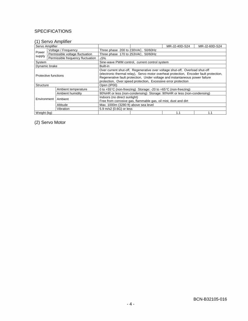
SPECIFICATIONS
(1) Servo AmplifierServo Amplifier MR-J2-40D-S24 MR-J2-60D-S24
Voltage / Frequency Three phase 200 to 230VAC, 50/60HzPermissible voltage fluctuation Three phase 170 to 253VAC, 50/60Hz
Powersupply
Permissible frequency fluctuation ±5%System Sine-wave PWM control, current control systemDynamic brake Built-in
Protective functions
Over current shut-off, Regenerative over voltage shut-off, Overload shut-off(electronic thermal relay), Servo motor overheat protection, Encoder fault protection,Regenerative fault protection, Under voltage and instantaneous power failureprotection, Over speed protection, Excessive error protection
Structure Open (IP00)Ambient temperature 0 to +55°C (non-freezing) Storage: -20 to +65°C (non-freezing)Ambient humidity 90%HR or less (non-condensing) Storage: 90%HR or less (non-condensing)
AmbientIndoors (no direct sunlight)Free from corrosive gas, flammable gas, oil mist, dust and dirt
Altitude Max. 1000m (3280 ft) above sea level
Environment
Vibration 5.9 m/s2 {0.6G} or lessWeight (kg) 1.1 1.1
(2) Servo Motor
BCN-B32105-016- 5 -
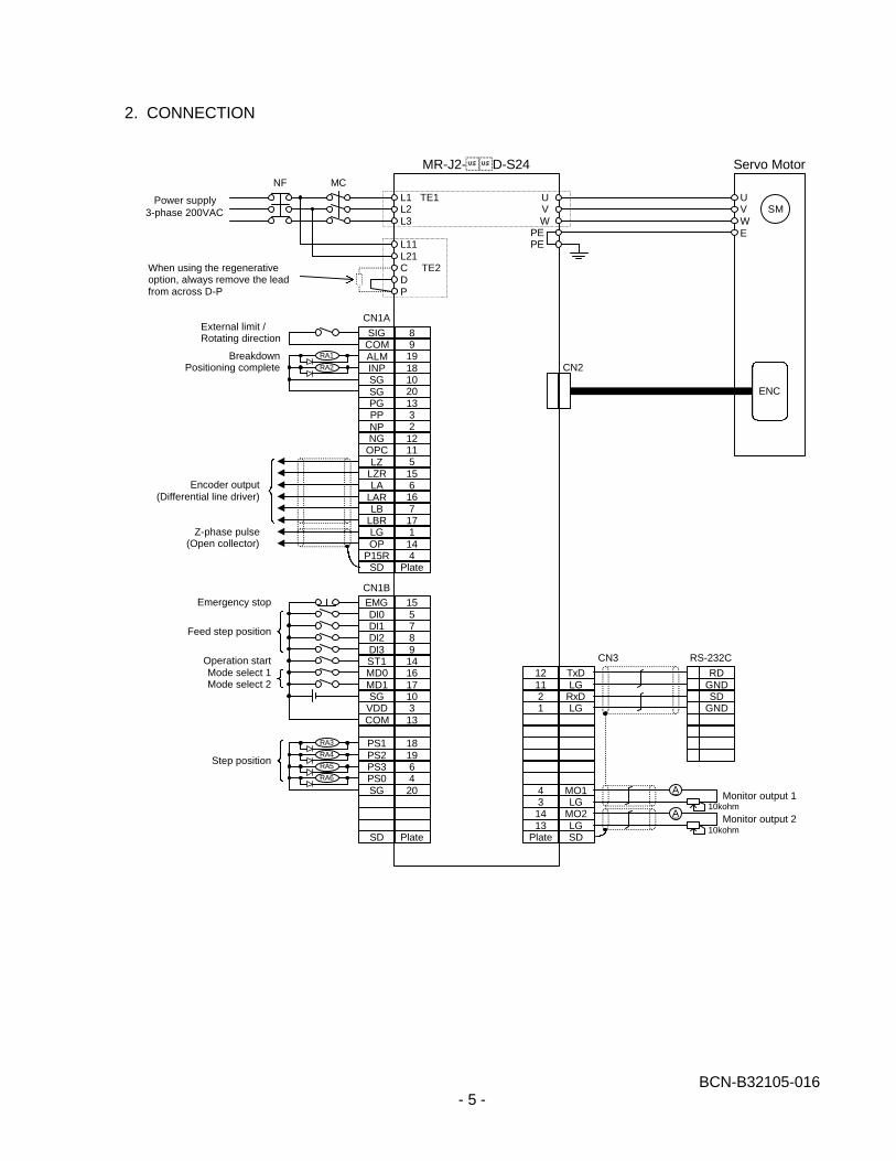
2. CONNECTION
MR-J2-��D-S24
L1 TE1L2L3
UVW
PEPE
8919181020133212115156167171144
Plate
SIGCOMALMINPSGSGPGPPNPNG
OPCLZ
LZRLA
LARLB
LBR
OPP15RSD
LG
15578914161710313
18196420
Plate
EMGDI0DI1DI2DI3ST1MD0MD1SG
VDDCOM
PS1PS2PS3PS0SG
SD
L11L21C TE2DP
MCNF
121121
431413
Plate
TxDLG
RxDLG
MO1
MO2LGSD
LG
UVWE
SM
ENC
CN2
Servo Motor
RDGNDSD
GND
CN3 RS-232C
A
10kohmMonitor output 1
A
10kohmMonitor output 2
Power supply3-phase 200VAC
When using the regenerativeoption, always remove the leadfrom across D-P
CN1A
RA1
RA2
RA3
RA4
RA5
RA6
CN1B
External limit /Rotating direction
BreakdownPositioning complete
Encoder output(Differential line driver)
Z-phase pulse(Open collector)
Emergency stop
Feed step position
Operation startMode select 1Mode select 2
Step position
BCN-B32105-016- 6 -
NOTE
CAUTION
1. Do not install a diode in the wrong polarity. If a diode is installed wrong polarity, servoamplifier may break and the protection circuit’s of the emergency stop etc. dose not work.
2. Install the emergency stop button.
REQUIREMENT
3. When using the regenerative brake option, always remove the lead from across D-P.4. CN1A, CN1B and CN2 are same shape connector. Mis-connection causes breakdown.5. Total current of external relays should be 80mA or less. Supply the interface power from
outside if the total current of external relays is over than 80mA.
MEMO
6. Short the external emergency stop signal during driving. (‘B’ type contact is required)7. The same name signals are connected inside.8. The Breakdown signal (ALM) turns on electricity when the servo amplifier is normal
condition (no alarm). When this signal turns off (alarm occurs), stop the controller signalby the sequence program.
9. Connect the shield wire to the plate (ground plate) of the connector.
BCN-B32105-016- 7 -
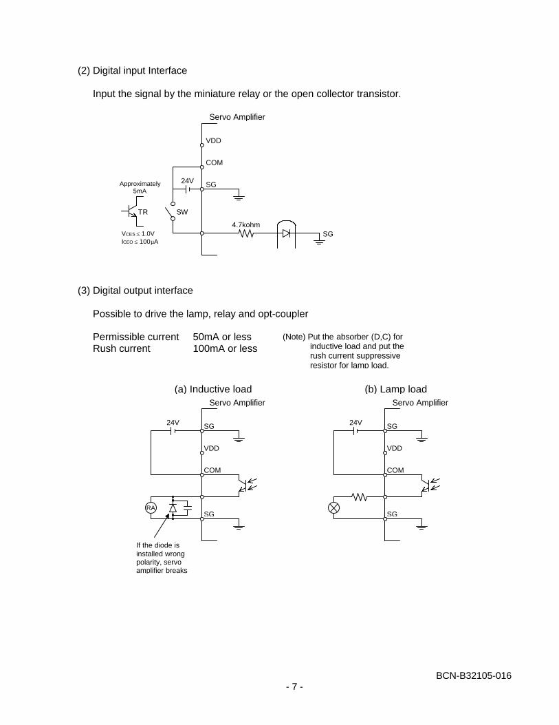
(2) Digital input Interface
Input the signal by the miniature relay or the open collector transistor.
(3) Digital output interface
Possible to drive the lamp, relay and opt-coupler
Permissible current 50mA or lessRush current 100mA or less
VDD
COM
SG24V
SW
4.7kohmSG
TR
Approximately5mA
VCES ≤ 1.0VICEO ≤ 100µA
Servo Amplifier
VDD
COM
SG
24V
Servo Amplifier
(a) Inductive load
SG
RA
If the diode isinstalled wrongpolarity, servoamplifier breaks
VDD
COM
SG
24V
Servo Amplifier
(b) Lamp load
SG
(Note) Put the absorber (D,C) forinductive load and put therush current suppressiveresistor for lamp load.
BCN-B32105-016- 8 -
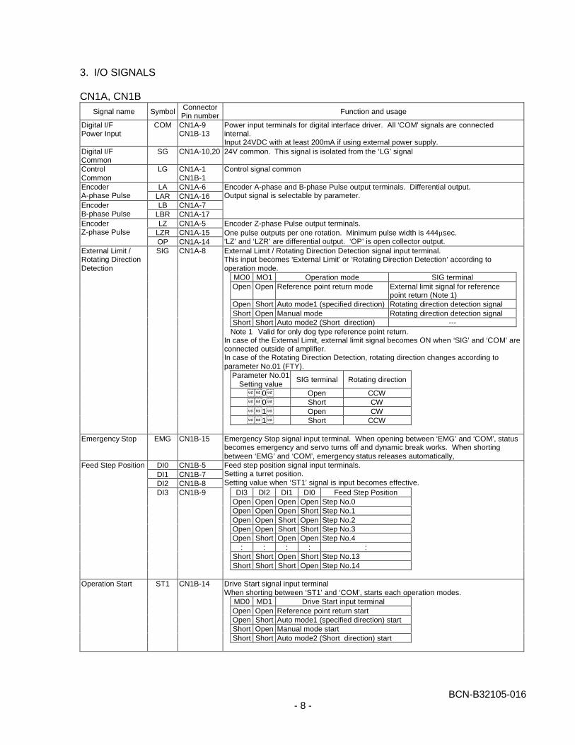
3. I/O SIGNALS
CN1A, CN1BSignal name Symbol
ConnectorPin number
Function and usage
Digital I/FPower Input
COM CN1A-9CN1B-13
Power input terminals for digital interface driver. All ‘COM’ signals are connectedinternal.Input 24VDC with at least 200mA if using external power supply.
Digital I/FCommon
SG CN1A-10,20 24V common. This signal is isolated from the ‘LG’ signal
ControlCommon
LG CN1A-1CN1B-1
Control signal common
LA CN1A-6EncoderA-phase Pulse LAR CN1A-16
LB CN1A-7EncoderB-phase Pulse LBR CN1A-17
Encoder A-phase and B-phase Pulse output terminals. Differential output.Output signal is selectable by parameter.
LZ CN1A-5LZR CN1A-15
EncoderZ-phase Pulse
OP CN1A-14
Encoder Z-phase Pulse output terminals.One pulse outputs per one rotation. Minimum pulse width is 444µsec.‘LZ’ and ‘LZR’ are differential output. ‘OP’ is open collector output.External Limit / Rotating Direction Detection signal input terminal.This input becomes ‘External Limit’ or ‘Rotating Direction Detection’ according tooperation mode.
MO0 MO1 Operation mode SIG terminalOpen Open Reference point return mode External limit signal for reference
point return (Note 1)Open Short Auto mode1 (specified direction) Rotating direction detection signalShort Open Manual mode Rotating direction detection signalShort Short Auto mode2 (Short direction) ---
Note 1 Valid for only dog type reference point return.In case of the External Limit, external limit signal becomes ON when ‘SIG’ and ‘COM’ areconnected outside of amplifier.In case of the Rotating Direction Detection, rotating direction changes according toparameter No.01 (FTY).
Parameter No.01Setting value
SIG terminal Rotating direction
��0� Open CCW��0� Short CW��1� Open CW��1� Short CCW
External Limit /Rotating DirectionDetection
SIG CN1A-8
Emergency Stop EMG CN1B-15 Emergency Stop signal input terminal. When opening between ‘EMG’ and ‘COM’, statusbecomes emergency and servo turns off and dynamic break works. When shortingbetween ‘EMG’ and ‘COM’, emergency status releases automatically,
DI0 CN1B-5DI1 CN1B-7DI2 CN1B-8
Feed step position signal input terminals.Setting a turret position.Setting value when ‘ST1’ signal is input becomes effective.
DI3 DI2 DI1 DI0 Feed Step PositionOpen Open Open Open Step No.0Open Open Open Short Step No.1Open Open Short Open Step No.2Open Open Short Short Step No.3Open Short Open Open Step No.4
: : : : :Short Short Open Short Step No.13Short Short Short Open Step No.14
Feed Step Position
DI3 CN1B-9
Drive Start signal input terminalWhen shorting between ‘ST1’ and ‘COM’, starts each operation modes.
MD0 MD1 Drive Start input terminalOpen Open Reference point return startOpen Short Auto mode1 (specified direction) startShort Open Manual mode startShort Short Auto mode2 (Short direction) start
Operation Start ST1 CN1B-14
BCN-B32105-016- 9 -
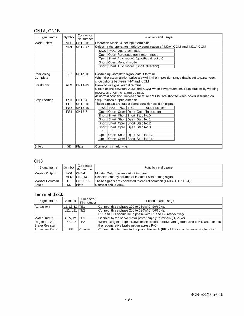
CN1A, CN1BSignal name Symbol
ConnectorPin number
Function and usage
MD0 CN1B-16 Operation Mode Select input terminals.Selecting the operation mode by combination of ‘MD0’-‘COM’ and ‘MD1’-‘COM’
MO0 MO1 Operation modeOpen Open Reference point return modeOpen Short Auto mode1 (specified direction)Short Open Manual modeShort Short Auto mode2 (Short direction)
Mode SelectMD1 CN1B-17
PositioningComplete
INP CN1A-18 Positioning Complete signal output terminal.When the accumulation pulse are within the in-position range that is set to parameter,circuit shorts between ‘INP’ and ‘COM’.
Breakdown ALM CN1A-19 Breakdown signal output terminal.Circuit opens between ‘ALM’ and ‘COM’ when power turns off, base shut off by workingprotection circuit, or alarm outputs.At normal condition, between ‘ALM’ and ‘COM’ are shorted when power is turned on.
PS0 CN1B-4PS1 CN1B-18
Step Position output terminals.These signals are output same condition as ‘INP’ signal.
PS2 CN1B-19 PS3 PS2 PS1 PS0 Step PositionOpen Open Open Open Out of in-positionShort Short Short Short Step No.0Short Short Short Open Step No.1Short Short Open Short Step No.2Short Short Open Open Step No.3
: : : : :Open Open Short Open Step No.13Open Open Open Short Step No.14
Step Position
PS3 CN1B-6
Shield SD Plate Connecting shield wire.
CN3Signal name Symbol
ConnectorPin number
Function and usage
MO1 CN3-4Monitor OutputMO2 CN3-14
Monitor Output signal output terminal.Selected data by parameter is output with analog signal.
Monitor Common LG CN3-3,13 These signals are connected to control common (CN1A-1, CN1B-1).Shield SD Plate Connect shield wire.
Terminal BlockSignal name Symbol
ConnectorPin number
Function and usage
L1, L2, L3 TE1 Connect three-phase 200 to 230VAC, 50/60Hz.AC CurrentL11, L21 TE2 Connect three-phase 200 to 230VAC, 50/60Hz.
L11 and L21 should be in phase with L1 and L2, respectively.Motor Output U, V, W TE1 Connect to the servo motor power supply terminals (U, V, W)RegenerativeBrake Resister
P, C, D TE2 When using the regenerative brake option, remove wiring from across P-D and connectthe regenerative brake option across P-C.
Protective Earth PE Chassis Connect this terminal to the protective earth (PE) of the servo motor at single point.
BCN-B32105-016- 10 -
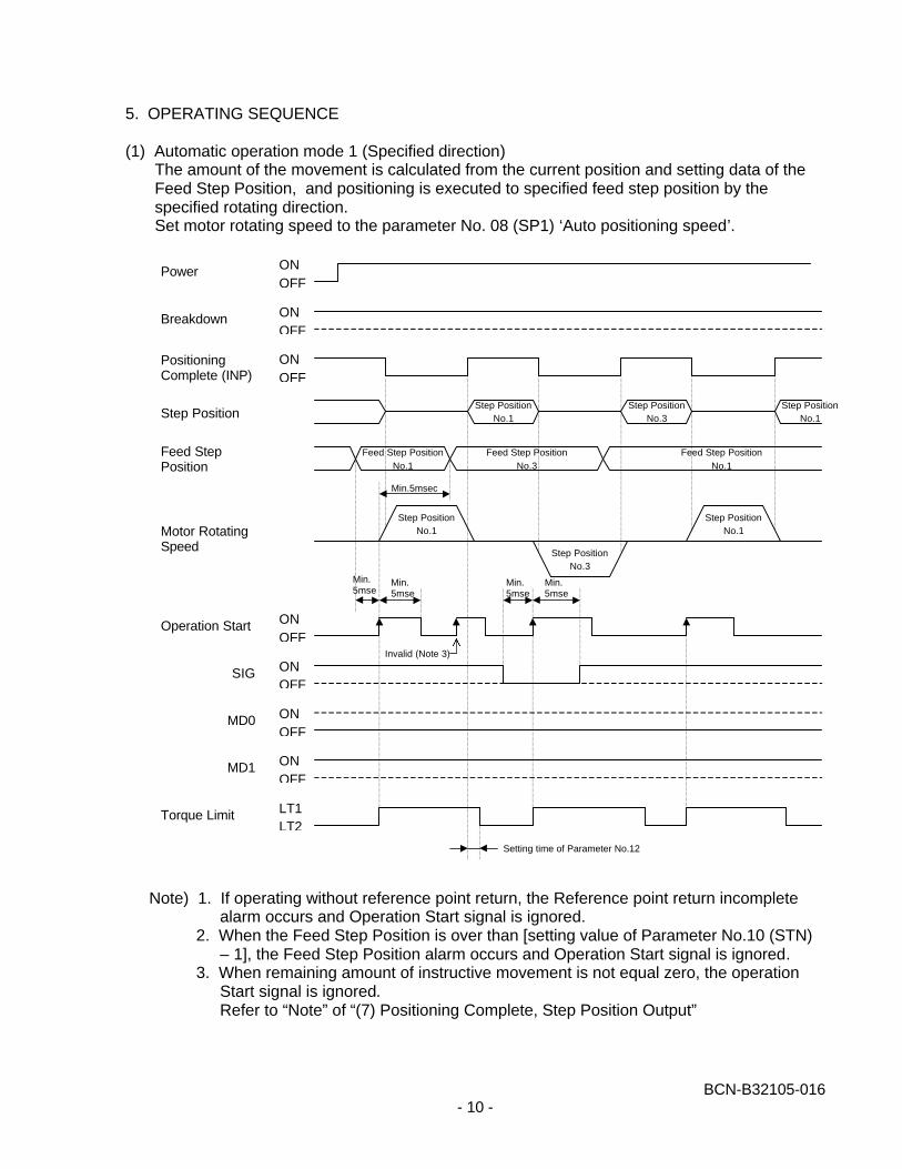
5. OPERATING SEQUENCE
(1) Automatic operation mode 1 (Specified direction)The amount of the movement is calculated from the current position and setting data of theFeed Step Position, and positioning is executed to specified feed step position by thespecified rotating direction.Set motor rotating speed to the parameter No. 08 (SP1) ‘Auto positioning speed’.
Note) 1. If operating without reference point return, the Reference point return incompletealarm occurs and Operation Start signal is ignored.
2. When the Feed Step Position is over than [setting value of Parameter No.10 (STN)– 1], the Feed Step Position alarm occurs and Operation Start signal is ignored.
3. When remaining amount of instructive movement is not equal zero, the operationStart signal is ignored.Refer to “Note” of “(7) Positioning Complete, Step Position Output”
ONOFF
Power
Breakdown
PositioningComplete (INP)
ONOFF
ONOFF
ONOFF
ONOFF
ONOFF
ONOFF
LT1LT2
Step Position
Feed StepPosition
Motor RotatingSpeed
Operation Start
SIG
MD0
MD1
Torque Limit
Step PositionNo.1
Step PositionNo.3
Step PositionNo.1
Feed Step PositionNo.1
Feed Step PositionNo.3
Feed Step PositionNo.1
Step PositionNo.1
Step PositionNo.3
Step PositionNo.1
Min.5msec
Min.5msec
Min.5msec
Min.5msec
Min.5msec
Invalid (Note 3)
Setting time of Parameter No.12
BCN-B32105-016- 11 -
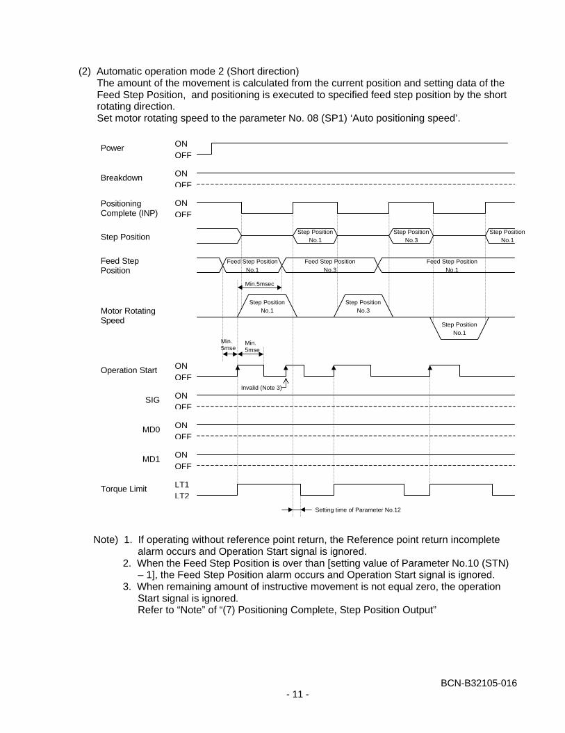
(2) Automatic operation mode 2 (Short direction)The amount of the movement is calculated from the current position and setting data of theFeed Step Position, and positioning is executed to specified feed step position by the shortrotating direction.Set motor rotating speed to the parameter No. 08 (SP1) ‘Auto positioning speed’.
Note) 1. If operating without reference point return, the Reference point return incompletealarm occurs and Operation Start signal is ignored.
2. When the Feed Step Position is over than [setting value of Parameter No.10 (STN)– 1], the Feed Step Position alarm occurs and Operation Start signal is ignored.
3. When remaining amount of instructive movement is not equal zero, the operationStart signal is ignored.Refer to “Note” of “(7) Positioning Complete, Step Position Output”
ONOFF
Power
Breakdown
PositioningComplete (INP)
ONOFF
ONOFF
ONOFF
ONOFF
ONOFF
ONOFF
LT1LT2
Step Position
Feed StepPosition
Motor RotatingSpeed
Operation Start
SIG
MD0
MD1
Torque Limit
Step PositionNo.1
Step PositionNo.3
Step PositionNo.1
Feed Step PositionNo.1
Feed Step PositionNo.3
Feed Step PositionNo.1
Step PositionNo.1
Step PositionNo.1
Step PositionNo.3
Min.5msec
Min.5msec
Min.5msec
Invalid (Note 3)
Setting time of Parameter No.12
BCN-B32105-016- 12 -
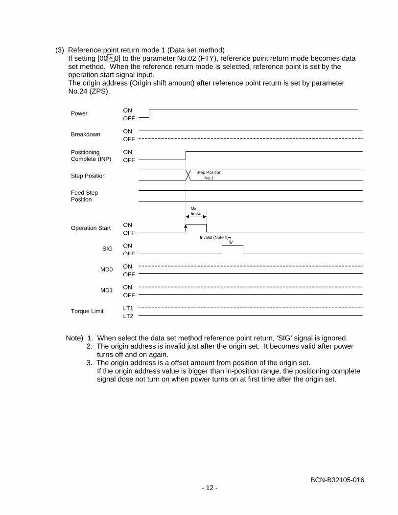
(3) Reference point return mode 1 (Data set method)If setting [00�0] to the parameter No.02 (FTY), reference point return mode becomes dataset method. When the reference return mode is selected, reference point is set by theoperation start signal input.The origin address (Origin shift amount) after reference point return is set by parameterNo.24 (ZPS).
Note) 1. When select the data set method reference point return, ‘SIG’ signal is ignored.2. The origin address is invalid just after the origin set. It becomes valid after power
turns off and on again.3. The origin address is a offset amount from position of the origin set.
If the origin address value is bigger than in-position range, the positioning completesignal dose not turn on when power turns on at first time after the origin set.
ONOFF
Power
Breakdown
PositioningComplete (INP)
ONOFF
ONOFF
ONOFF
ONOFF
ONOFF
ONOFF
LT1LT2
Step Position
Feed StepPosition
Operation Start
SIG
MD0
MD1
Torque Limit
Step PositionNo.1
Min.5msec
Invalid (Note 1)
BCN-B32105-016- 13 -
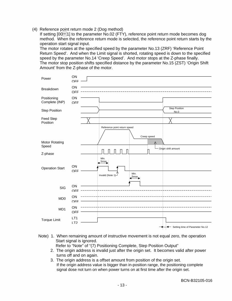
(4) Reference point return mode 2 (Dog method)If setting [00�1] to the parameter No.02 (FTY), reference point return mode becomes dogmethod. When the reference return mode is selected, the reference point return starts by theoperation start signal input.The motor rotates at the specified speed by the parameter No.13 (ZRF) ‘Reference PointReturn Speed’. And when the Limit signal is shorted, rotating speed is down to the specifiedspeed by the parameter No.14 ‘Creep Speed’. And motor stops at the Z-phase finally.The motor stop position shifts specified distance by the parameter No.15 (ZST) ‘Origin ShiftAmount’ from the Z-phase of the motor.
Note) 1. When remaining amount of instructive movement is not equal zero, the operationStart signal is ignored.Refer to “Note” of “(7) Positioning Complete, Step Position Output”
2. The origin address is invalid just after the origin set. It becomes valid after powerturns off and on again.
3. The origin address is a offset amount from position of the origin set.If the origin address value is bigger than in-position range, the positioning completesignal dose not turn on when power turns on at first time after the origin set.
ONOFF
Power
Breakdown
PositioningComplete (INP)
ONOFF
ONOFF
ONOFF
ONOFF
ONOFF
ONOFF
LT1LT2
Step Position
Feed StepPosition
Motor RotatingSpeed
Operation Start
SIG
MD0
MD1
Torque Limit
Step PositionNo.0
Min.5msec
Invalid (Note 1)
Setting time of Parameter No.12
Reference point return speed
Creep speed
Origin shift amount
Min.5msec
Z-phase
BCN-B32105-016- 14 -
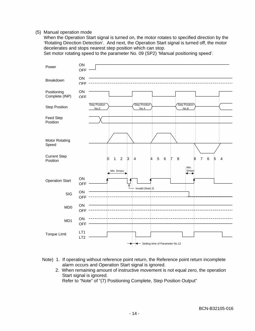
(5) Manual operation modeWhen the Operation Start signal is turned on, the motor rotates to specified direction by the‘Rotating Direction Detection’. And next, the Operation Start signal is turned off, the motordecelerates and stops nearest step position which can stop.Set motor rotating speed to the parameter No. 09 (SP2) ‘Manual positioning speed’.
Note) 1. If operating without reference point return, the Reference point return incompletealarm occurs and Operation Start signal is ignored.
2. When remaining amount of instructive movement is not equal zero, the operationStart signal is ignored.Refer to “Note” of “(7) Positioning Complete, Step Position Output”
ONOFF
Power
Breakdown
PositioningComplete (INP)
ONOFF
ONOFF
ONOFF
ONOFF
ONOFF
ONOFF
LT1LT2
Step Position
Feed StepPosition
Motor RotatingSpeed
Operation Start
SIG
MD0
MD1
Torque Limit
Step PositionNo.4
Step PositionNo.8
Min. 5msec
Invalid (Note 2)
Setting time of Parameter No.12
Step PositionNo.0
0 1 2 3 4 4 5 6 8 8 7 6 457Current StepPosition
Min.5msec
BCN-B32105-016- 15 -
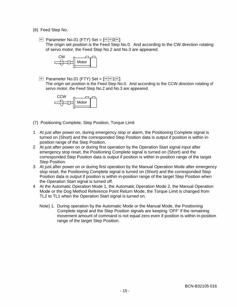
(6) Feed Step No.
� Parameter No.01 (FTY) Set = [��0�]The origin set position is the Feed Step No.0. And according to the CW direction rotatingof servo motor, the Feed Step No.2 and No.3 are appeared.
� Parameter No.01 (FTY) Set = [��1�]The origin set position is the Feed Step No.0. And according to the CCW direction rotating ofservo motor, the Feed Step No.2 and No.3 are appeared.
(7) Positioning Complete, Step Position, Torque Limit
1 At just after power on, during emergency stop or alarm, the Positioning Complete signal isturned on (Short) and the corresponded Step Position data is output if position is within in-position range of the Step Position.
2 At just after power on or during first operation by the Operation Start signal input afteremergency stop reset, the Positioning Complete signal is turned on (Short) and thecorresponded Step Position data is output if position is within in-position range of the targetStep Position.
3 At just after power on or during first operation by the Manual Operation Mode after emergencystop reset, the Positioning Complete signal is turned on (Short) and the corresponded StepPosition data is output if position is within in-position range of the target Step Position whenthe Operation Start signal is turned off.
4 At the Automatic Operation Mode 1, the Automatic Operation Mode 2, the Manual OperationMode or the Dog Method Reference Point Return Mode, the Torque Limit is changed fromTL2 to TL1 when the Operation Start signal is turned on.
Note) 1. During operation by the Automatic Mode or the Manual Mode, the PositioningComplete signal and the Step Position signals are keeping ‘OFF’ if the remainingmovement amount of command is not equal zero even if position is within in-positionrange of the target Step Position.
MotorCW
Motor
CCW
BCN-B32105-016- 16 -
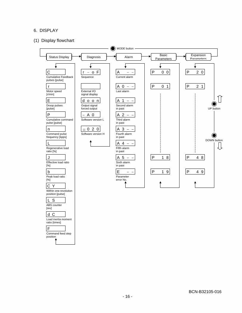
6. DISPLAY
(1) Display flowchart
Status Display Diagnosis AlarmBasic
ParametersExpansionParameters
Cumulative Feedbackpulses [pulse]
Motor speed[r/min]
Droop pulses[pulse]
Cumulative commandpulse [pulse]
Command pulsefrequency [kpps]
Regenerative loadratio [%]
Effective load ratio[%]
Peak load ratio[%]
Within one-revolutionposition [pulse]
ABS counter[rev]
Load inertia momentratio [times]
Command feed stepposition
Sequence
r − o FC
r
E
P
n
L
b
J
C Y
L S
d C
F
External I/Osignal display
Output signalforced output
d o o n
Software version L
− A 0
Software version H
0 2 0
Current alarm
A − −
Last alarm
A 0 − −
Second alarmin past
A 1 − −
Third alarmin past
A 2 − −
Fourth alarmin past
A 3 − −
Fifth alarmin past
A 4 − −
Sixth alarmin past
A 5 − −
Parametererror No.
E − −
P 0 0
P 0 1
P 1 8
P 1 9
P 2 0
P 2 1
P 4 8
P 4 9
UP button
DOWN button
MODE button
BCN-B32105-016- 17 -
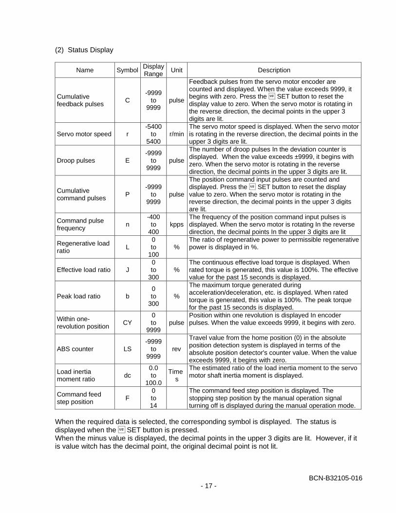
(2) Status Display
Name SymbolDisplayRange
Unit Description
Cumulativefeedback pulses
C-9999
to9999
pulse
Feedback pulses from the servo motor encoder arecounted and displayed. When the value exceeds 9999, itbegins with zero. Press the � SET button to reset thedisplay value to zero. When the servo motor is rotating inthe reverse direction, the decimal points in the upper 3digits are lit.
Servo motor speed r-5400
to5400
r/minThe servo motor speed is displayed. When the servo motoris rotating in the reverse direction, the decimal points in theupper 3 digits are lit.
Droop pulses E-9999
to9999
pulse
The number of droop pulses In the deviation counter isdisplayed. When the value exceeds ±9999, it begins withzero. When the servo motor is rotating in the reversedirection, the decimal points in the upper 3 digits are lit.
Cumulativecommand pulses
P-9999
to9999
pulse
The position command input pulses are counted anddisplayed. Press the � SET button to reset the displayvalue to zero. When the servo motor is rotating in thereverse direction, the decimal points in the upper 3 digitsare lit.
Command pulsefrequency
n-400
to400
kppsThe frequency of the position command input pulses isdisplayed. When the servo motor is rotating In the reversedirection, the decimal points In the upper 3 digits are lit
Regenerative loadratio
L0to
100%
The ratio of regenerative power to permissible regenerativepower is displayed in %.
Effective load ratio J0to
300%
The continuous effective load torque is displayed. Whenrated torque is generated, this value is 100%. The effectivevalue for the past 15 seconds is displayed.
Peak load ratio b0to
300%
The maximum torque generated duringacceleration/deceleration, etc. is displayed. When ratedtorque is generated, this value is 100%. The peak torquefor the past 15 seconds is displayed.
Within one-revolution position
CY0to
9999pulse
Position within one revolution is displayed In encoderpulses. When the value exceeds 9999, it begins with zero.
ABS counter LS-9999
to9999
rev
Travel value from the home position (0) in the absoluteposition detection system is displayed in terms of theabsolute position detector's counter value. When the valueexceeds 9999, it begins with zero.
Load inertiamoment ratio
dc0.0to
100.0
Times
The estimated ratio of the load inertia moment to the servomotor shaft inertia moment is displayed.
Command feedstep position
F0to14
The command feed step position is displayed. Thestopping step position by the manual operation signalturning off is displayed during the manual operation mode.
When the required data is selected, the corresponding symbol is displayed. The status isdisplayed when the � SET button is pressed.When the minus value is displayed, the decimal points in the upper 3 digits are lit. However, if itis value witch has the decimal point, the original decimal point is not lit.
BCN-B32105-016- 18 -
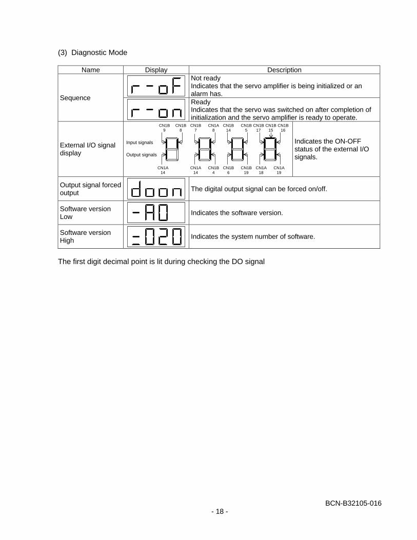
(3) Diagnostic Mode
Name Display DescriptionNot readyIndicates that the servo amplifier is being initialized or analarm has.
SequenceReadyIndicates that the servo was switched on after completion ofinitialization and the servo amplifier is ready to operate.
External I/O signaldisplay
Indicates the ON-OFFstatus of the external I/Osignals.
Output signal forcedoutput
The digital output signal can be forced on/off.
Software versionLow
Indicates the software version.
Software versionHigh
Indicates the system number of software.
The first digit decimal point is lit during checking the DO signal
Input signals
CN1B9
CN1A14
CN1B8
Output signals
CN1B7
CN1A14
CN1A8
CN1B4
CN1B14
CN1B6
CN1B5
CN1B19
CN1B17
CN1A18
CN1B16
CN1A19
CN1B15
BCN-B32105-016- 19 -
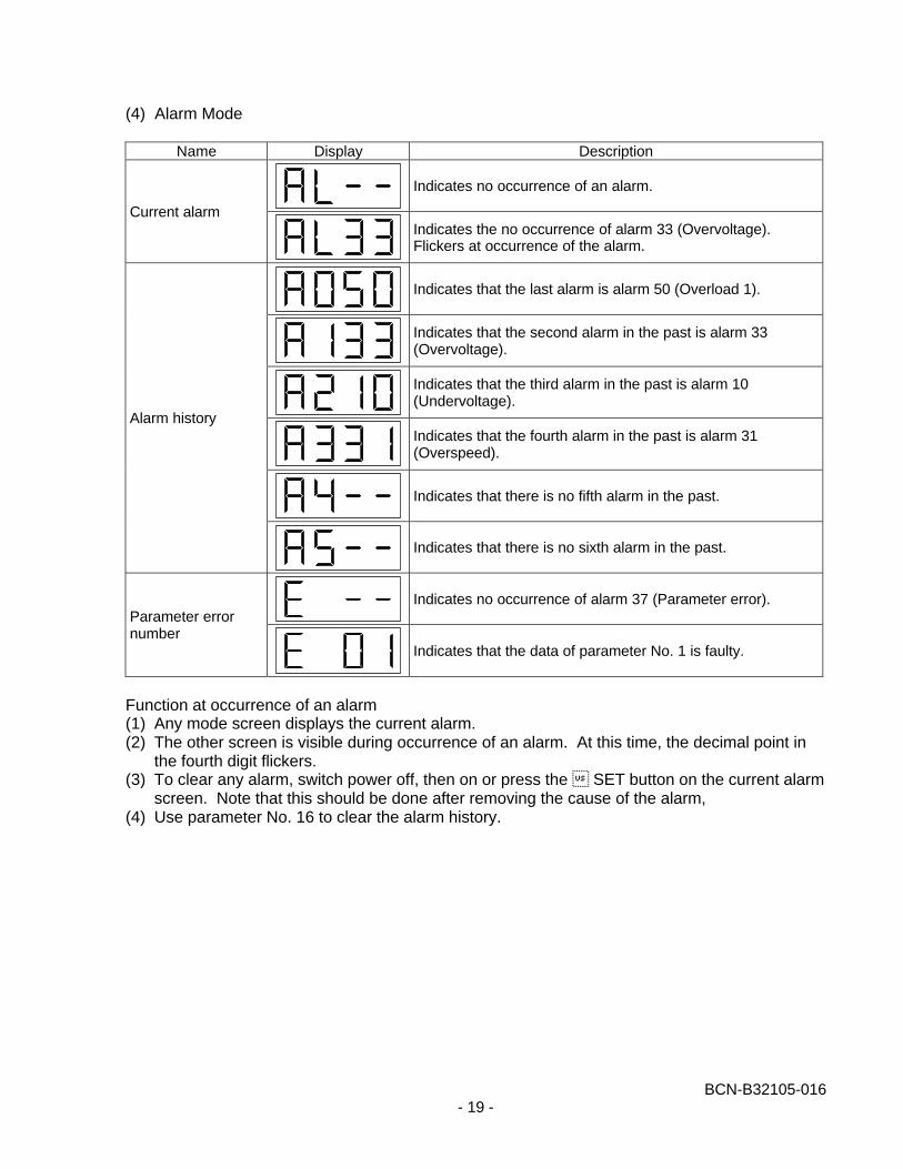
(4) Alarm Mode
Name Display Description
Indicates no occurrence of an alarm.
Current alarmIndicates the no occurrence of alarm 33 (Overvoltage).Flickers at occurrence of the alarm.
Indicates that the last alarm is alarm 50 (Overload 1).
Indicates that the second alarm in the past is alarm 33(Overvoltage).
Indicates that the third alarm in the past is alarm 10(Undervoltage).
Indicates that the fourth alarm in the past is alarm 31(Overspeed).
Indicates that there is no fifth alarm in the past.
Alarm history
Indicates that there is no sixth alarm in the past.
Indicates no occurrence of alarm 37 (Parameter error).Parameter errornumber
Indicates that the data of parameter No. 1 is faulty.
Function at occurrence of an alarm(1) Any mode screen displays the current alarm.(2) The other screen is visible during occurrence of an alarm. At this time, the decimal point in
the fourth digit flickers.(3) To clear any alarm, switch power off, then on or press the � SET button on the current alarm
screen. Note that this should be done after removing the cause of the alarm,(4) Use parameter No. 16 to clear the alarm history.
BCN-B32105-016- 20 -
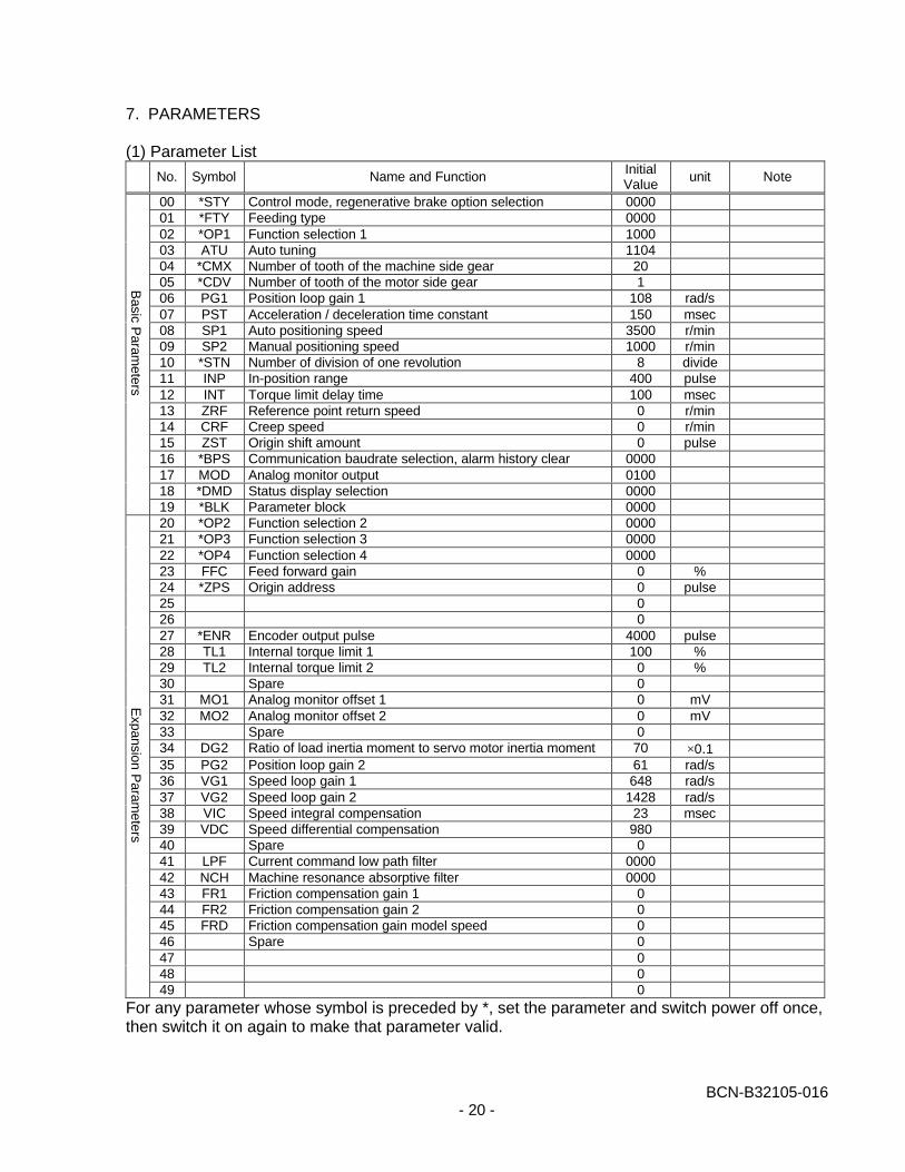
7. PARAMETERS
(1) Parameter List
No. Symbol Name and Function InitialValue
unit Note
00 *STY Control mode, regenerative brake option selection 000001 *FTY Feeding type 000002 *OP1 Function selection 1 100003 ATU Auto tuning 110404 *CMX Number of tooth of the machine side gear 2005 *CDV Number of tooth of the motor side gear 106 PG1 Position loop gain 1 108 rad/s07 PST Acceleration / deceleration time constant 150 msec08 SP1 Auto positioning speed 3500 r/min09 SP2 Manual positioning speed 1000 r/min10 *STN Number of division of one revolution 8 divide11 INP In-position range 400 pulse12 INT Torque limit delay time 100 msec13 ZRF Reference point return speed 0 r/min14 CRF Creep speed 0 r/min15 ZST Origin shift amount 0 pulse16 *BPS Communication baudrate selection, alarm history clear 000017 MOD Analog monitor output 010018 *DMD Status display selection 000019 *BLK Parameter block 000020 *OP2 Function selection 2 000021 *OP3 Function selection 3 000022 *OP4 Function selection 4 000023 FFC Feed forward gain 0 %24 *ZPS Origin address 0 pulse25 026 027 *ENR Encoder output pulse 4000 pulse28 TL1 Internal torque limit 1 100 %29 TL2 Internal torque limit 2 0 %30 Spare 031 MO1 Analog monitor offset 1 0 mV32 MO2 Analog monitor offset 2 0 mV33 Spare 034 DG2 Ratio of load inertia moment to servo motor inertia moment 70 ×0.135 PG2 Position loop gain 2 61 rad/s36 VG1 Speed loop gain 1 648 rad/s37 VG2 Speed loop gain 2 1428 rad/s38 VIC Speed integral compensation 23 msec39 VDC Speed differential compensation 98040 Spare 041 LPF Current command low path filter 000042 NCH Machine resonance absorptive filter 000043 FR1 Friction compensation gain 1 044 FR2 Friction compensation gain 2 045 FRD Friction compensation gain model speed 046 Spare 047 048 049 0
For any parameter whose symbol is preceded by *, set the parameter and switch power off once,then switch it on again to make that parameter valid.
Basic P
arameters
Expansion P
arameters
BCN-B32105-016- 21 -
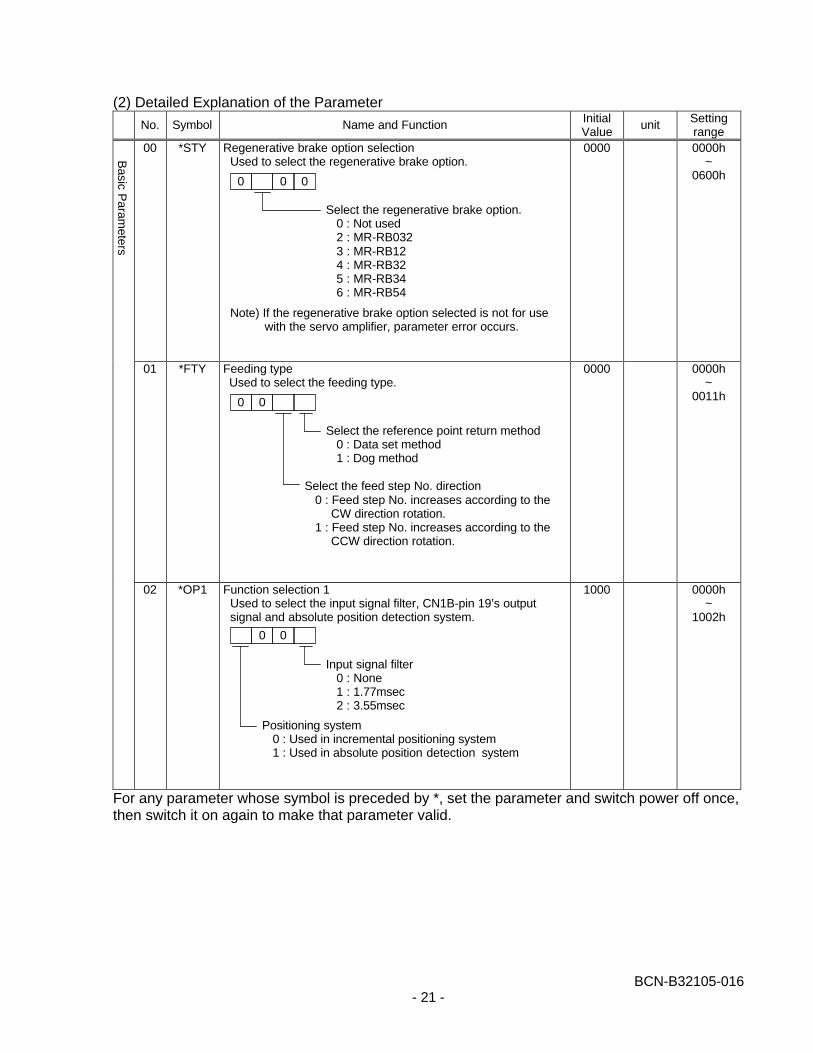
(2) Detailed Explanation of the Parameter
No. Symbol Name and Function InitialValue
unit Settingrange
00 *STY Regenerative brake option selection Used to select the regenerative brake option.
Note) If the regenerative brake option selected is not for usewith the servo amplifier, parameter error occurs.
0000 0000h~
0600h
01 *FTY Feeding typeUsed to select the feeding type.
0000 0000h~
0011h
02 *OP1 Function selection 1Used to select the input signal filter, CN1B-pin 19’s outputsignal and absolute position detection system.
1000 0000h~
1002h
For any parameter whose symbol is preceded by *, set the parameter and switch power off once,then switch it on again to make that parameter valid.
Basic P
arameters
0 0 0
Select the regenerative brake option.0 : Not used2 : MR-RB0323 : MR-RB124 : MR-RB325 : MR-RB346 : MR-RB54
0 0
Select the reference point return method0 : Data set method1 : Dog method
Select the feed step No. direction0 : Feed step No. increases according to the
CW direction rotation.1 : Feed step No. increases according to the
CCW direction rotation.
Positioning system0 : Used in incremental positioning system1 : Used in absolute position detection system
0 0
Input signal filter0 : None1 : 1.77msec2 : 3.55msec
BCN-B32105-016- 22 -
No. Symbol Name and Function InitialValue
unit Note
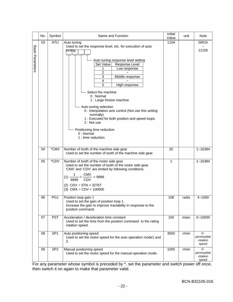
03 ATU Auto tuningUsed to set the response level, etc. for execution of autotuning.
1104 0001h~
1215h
04 *CMX Number of tooth of the machine side gear Used to set the number of tooth of the machine side gear.
20 1~16384
05 *CDV Number of tooth of the motor side gearUsed to set the number of tooth of the motor side gear.‘CMX’ and ‘CDV’ are limited by following conditions.
(1) < < 9999
(2) CDV × STN < 32767(3) CMX × CDV < 100000
1 1~16384
06 PG1 Position loop gain 1Used to set the gain of position loop 1.Increase the gain to improve tractability in response to theposition command.
108 rad/s 4~1000
07 PST Acceleration / deceleration time constantUsed to set the time from the position command to the ratingrotation speed.
150 msec 0~10000
08 SP1 Auto positioning speedUsed to set the motor speed for the auto operation mode1 and2.
3500 r/min 0~permissible
rotationspeed
09 SP2 Manual positioning speedUsed to set the motor speed for the manual operation mode.
1000 r/min 0~permissible
rotationspeed
For any parameter whose symbol is preceded by *, set the parameter and switch power off once,then switch it on again to make that parameter valid.
Select the machine0 : Normal1 : Large friction machine
Auto tuning response level settingSet Value Response Level
1 Low response2 ~3 Middle response4 ~5 High response
Auto tuning selection0 : Interpolation axis control (Not use this setting
normally)1 : Executed for both position and speed loops2 : Not use
Positioning time reduction0 : Normal1 : time reduction
9999
1
CDV
CMX
Basic P
arameters

BCN-B32105-016- 23 -
No. Symbol Name and Function InitialValue
unit Note
10 *STN Number of division of one revolutionUsed to set the number of divided of one revolution (Number ofcalculating positions)
8 divide 1~15
11 INP In-position rangeUsed to set the droop pulse range in witch the in-position (INP)signal will be output.
400 pulse 0~10000
12 INT Torque limit delay timeUsed to set the delay time from the positioning complete signal(INP) output to the torque limit becomes effective.
100 msec 0~1000
13 ZRF Reference point return speedUsed to set the motor rotation speed for the reference pointreturn.
0 r/min 0~permissible
rotationspeed
14 CRF Creep speedUsed to set the creep speed after the dog detection.
0 r/min 0~permissible
rotationspeed
15 ZST Origin shift amountUsed to set the shift amount from the encoder’s Z-phase pulsedetection position.
0 pulse 0~65535
16 *BPS Communication baudrate selection, alarm history clearUsed to select the communication baudrate for the RS-232Cand to clear the alarm history.
0000 0000h~
0011h
For any parameter whose symbol is preceded by *, set the parameter and switch power off once,then switch it on again to make that parameter valid.
Basic P
arameters
0 0
Selection of baudrate for RS-232C0 : 9600 [bps]1 : 19200 [bps]
Alarm history clear0 : Invalid1 : Valid
When alarm history clear is made valid, thealarm history is cleared at next power –on. Afterthe alarm history is cleared, the setting isautomatically made invalid (reset to 0).
BCN-B32105-016- 24 -
No. Symbol Name and Function InitialValue
unit Note
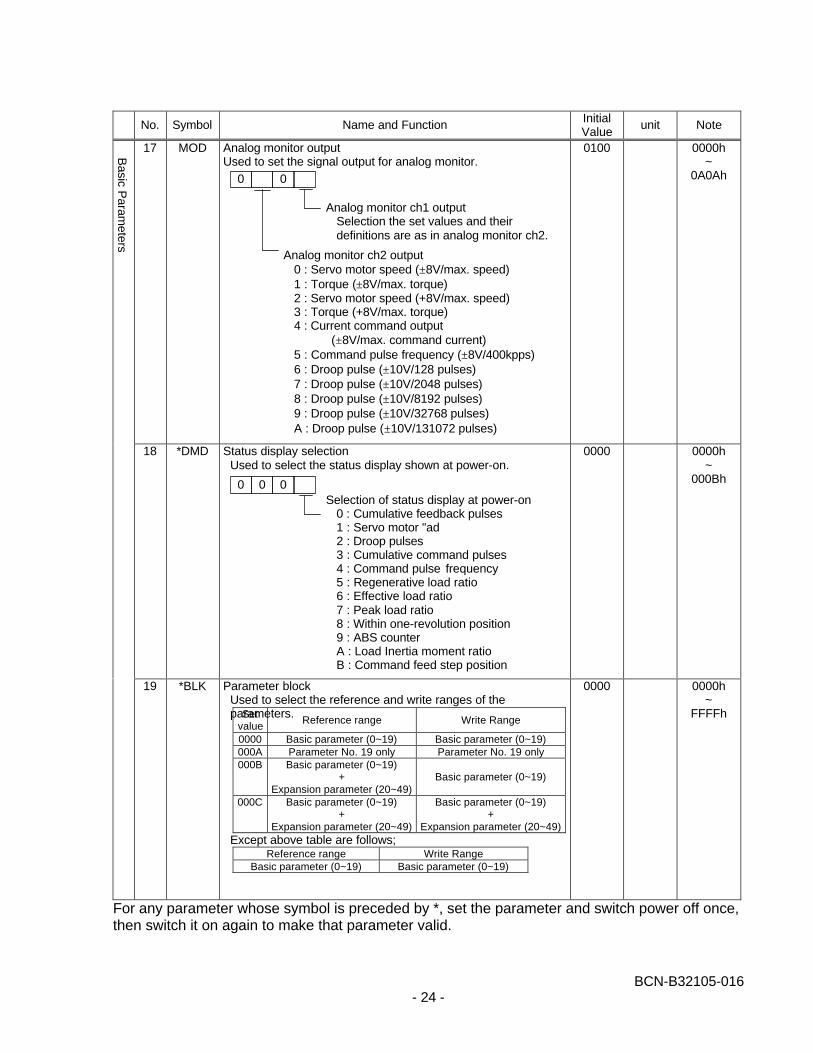
17 MOD Analog monitor outputUsed to set the signal output for analog monitor.
0100 0000h~
0A0Ah
18 *DMD Status display selectionUsed to select the status display shown at power-on.
0000 0000h~
000Bh
19 *BLK Parameter blockUsed to select the reference and write ranges of theparameters.
0000 0000h~
FFFFh
For any parameter whose symbol is preceded by *, set the parameter and switch power off once,then switch it on again to make that parameter valid.
Basic P
arameters
0 0
Analog monitor ch1 outputSelection the set values and theirdefinitions are as in analog monitor ch2.
Analog monitor ch2 output0 : Servo motor speed (±8V/max. speed)1 : Torque (±8V/max. torque)2 : Servo motor speed (+8V/max. speed)3 : Torque (+8V/max. torque)4 : Current command output
(±8V/max. command current)5 : Command pulse frequency (±8V/400kpps)6 : Droop pulse (±10V/128 pulses)7 : Droop pulse (±10V/2048 pulses)8 : Droop pulse (±10V/8192 pulses)9 : Droop pulse (±10V/32768 pulses)A : Droop pulse (±10V/131072 pulses)
0 0 0Selection of status display at power-on
0 : Cumulative feedback pulses1 : Servo motor "ad2 : Droop pulses3 : Cumulative command pulses4 : Command pulse frequency5 : Regenerative load ratio6 : Effective load ratio7 : Peak load ratio8 : Within one-revolution position9 : ABS counterA : Load Inertia moment ratioB : Command feed step position
Setvalue
Reference range Write Range
0000 Basic parameter (0~19) Basic parameter (0~19)000A Parameter No. 19 only Parameter No. 19 only000B Basic parameter (0~19)
+Expansion parameter (20~49)
Basic parameter (0~19)
000C Basic parameter (0~19)+
Expansion parameter (20~49)
Basic parameter (0~19)+
Expansion parameter (20~49)Except above table are follows;
Reference range Write RangeBasic parameter (0~19) Basic parameter (0~19)
BCN-B32105-016- 25 -
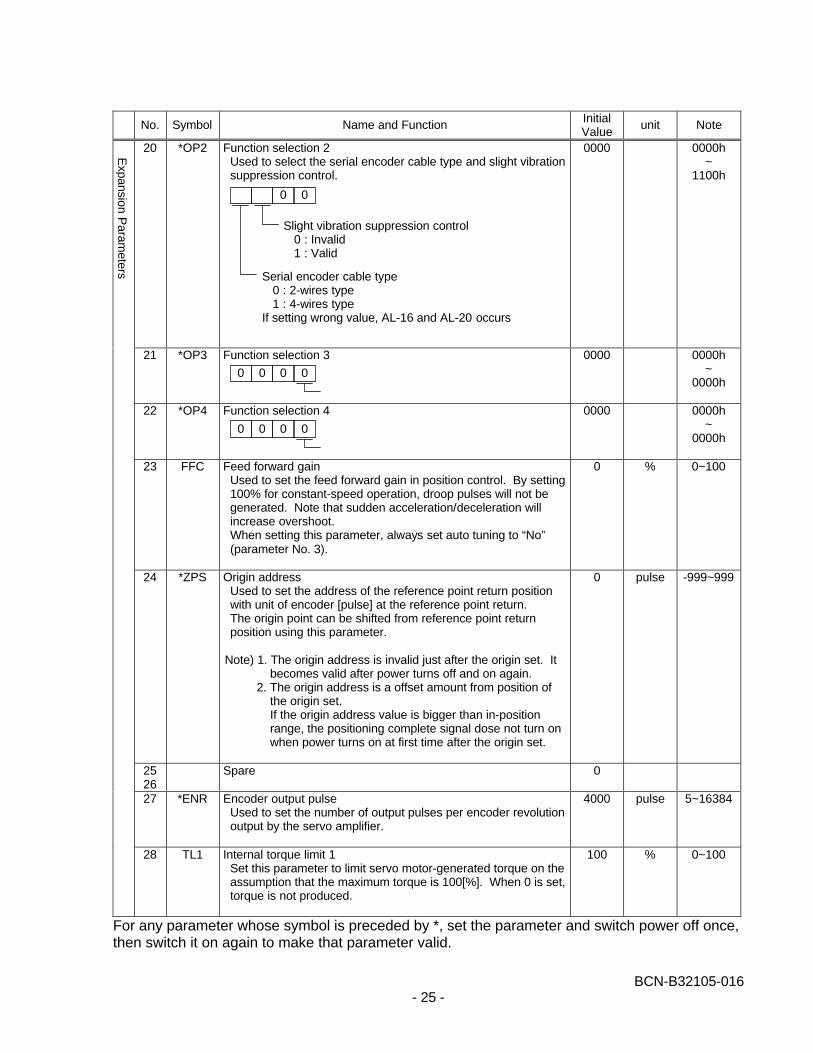
No. Symbol Name and Function InitialValue
unit Note
20 *OP2 Function selection 2Used to select the serial encoder cable type and slight vibrationsuppression control.
0000 0000h~
1100h
21 *OP3 Function selection 3 0000 0000h~
0000h
22 *OP4 Function selection 4 0000 0000h~
0000h
23 FFC Feed forward gainUsed to set the feed forward gain in position control. By setting100% for constant-speed operation, droop pulses will not begenerated. Note that sudden acceleration/deceleration willincrease overshoot.When setting this parameter, always set auto tuning to “No”(parameter No. 3).
0 % 0~100
24 *ZPS Origin addressUsed to set the address of the reference point return positionwith unit of encoder [pulse] at the reference point return.The origin point can be shifted from reference point returnposition using this parameter.
Note) 1. The origin address is invalid just after the origin set. Itbecomes valid after power turns off and on again.
2. The origin address is a offset amount from position ofthe origin set.If the origin address value is bigger than in-positionrange, the positioning complete signal dose not turn onwhen power turns on at first time after the origin set.
0 pulse -999~999
2526
Spare 0
27 *ENR Encoder output pulseUsed to set the number of output pulses per encoder revolutionoutput by the servo amplifier.
4000 pulse 5~16384
28 TL1 Internal torque limit 1Set this parameter to limit servo motor-generated torque on theassumption that the maximum torque is 100[%]. When 0 is set,torque is not produced.
100 % 0~100
For any parameter whose symbol is preceded by *, set the parameter and switch power off once,then switch it on again to make that parameter valid.
Expansion P
arameters
0 0
Slight vibration suppression control0 : Invalid1 : Valid
Serial encoder cable type0 : 2-wires type1 : 4-wires type
If setting wrong value, AL-16 and AL-20 occurs
0 0 0 0
0 0 0 0
BCN-B32105-016- 26 -
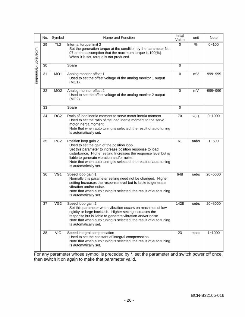
No. Symbol Name and Function InitialValue
unit Note
29 TL2 Internal torque limit 2Set the generation torque at the condition by the parameter No.07 on the assumption that the maximum torque is 100[%].When 0 is set, torque is not produced.
0 % 0~100
30 Spare 0
31 MO1 Analog monitor offset 1Used to set the offset voltage of the analog monitor 1 output(MO1).
0 mV -999~999
32 MO2 Analog monitor offset 2Used to set the offset voltage of the analog monitor 2 output(MO2).
0 mV -999~999
33 Spare 0
34 DG2 Ratio of load inertia moment to servo motor inertia momentUsed to set the ratio of the load inertia moment to the servomotor inertia moment.Note that when auto tuning is selected, the result of auto tuningIs automatically set.
70 ×0.1 0~1000
35 PG2 Position loop gain 2Used to set the gain of the position loop.Set this parameter to increase position response to loaddisturbance. Higher setting Increases the response level but isliable to generate vibration and/or noise.Note that when auto tuning is selected, the result of auto tuningIs automatically set.
61 rad/s 1~500
36 VG1 Speed loop gain 1Normally this parameter setting need not be changed. Highersetting Increases the response level but Is liable to generatevibration and/or noise.Note that when auto tuning is selected, the result of auto tuningIs automatically set.
648 rad/s 20~5000
37 VG2 Speed loop gain 2Set this parameter when vibration occurs on machines of lowrigidity or large backlash. Higher setting increases theresponse but is liable to generate vibration and/or noise.Note that when auto tuning is selected, the result of auto tuningIs automatically set.
1428 rad/s 20~8000
38 VIC Speed integral compensationUsed to set the constant of integral compensation.Note that when auto tuning is selected, the result of auto tuningIs automatically set.
23 msec 1~1000
For any parameter whose symbol is preceded by *, set the parameter and switch power off once,then switch it on again to make that parameter valid.
Expansion P
arameters
BCN-B32105-016- 27 -
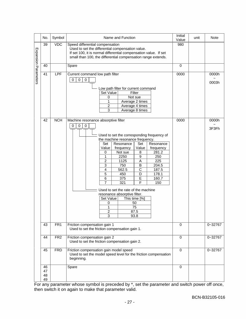
No. Symbol Name and Function InitialValue
unit Note
39 VDC Speed differential compensationUsed to set the differential compensation value.If set 100, it is normal differential compensation value. If setsmall than 100, the differential compensation range extends.
980
40 Spare 0
41 LPF Current command low path filter 0000 0000h~
0003h
42 NCH Machine resonance absorptive filter 0000 0000h~
3F3Fh
43 FR1 Friction compensation gain 1Used to set the friction compensation gain 1.
0 0~32767
44 FR2 Friction compensation gain 2Used to set the friction compensation gain 2.
0 0~32767
45 FRD Friction compensation gain model speedUsed to set the model speed level for the friction compensationbeginning.
0 0~32767
46474849
Spare 0
For any parameter whose symbol is preceded by *, set the parameter and switch power off once,then switch it on again to make that parameter valid.
Expansion P
arameters 0 0 0
Low path filter for current commandSet Value Filter
0 Not sue1 Average 2 times2 Average 4 times3 Average 8 times
0 0 0
Used to set the corresponding frequency ofthe machine resonance frequency.
SetValue
Resonancefrequency
SetValue
Resonancefrequency
0 Not sue 8 281.21 2250 9 2502 1125 A 2253 750 B 204.54 562.5 C 187.55 450 D 178.16 375 E 160.77 321 F 150
Used to set the rate of the machineresonance absorptive filter.
Set Value This time [%]0 501 752 87.53 93.8
BCN-B32105-016- 28 -
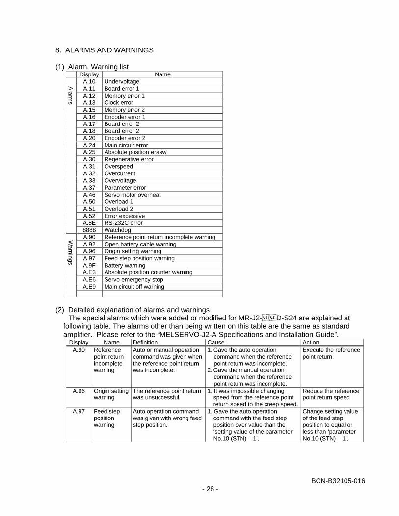
8. ALARMS AND WARNINGS
(1) Alarm, Warning listDisplay Name
A.10 UndervoltageA.11 Board error 1A.12 Memory error 1A.13 Clock errorA.15 Memory error 2A.16 Encoder error 1A.17 Board error 2A.18 Board error 2A.20 Encoder error 2A.24 Main circuit errorA.25 Absolute position eraswA.30 Regenerative errorA.31 OverspeedA.32 OvercurrentA.33 OvervoltageA.37 Parameter errorA.46 Servo motor overheatA.50 Overload 1A.51 Overload 2A.52 Error excessiveA.8E RS-232C error8888 WatchdogA.90 Reference point return incomplete warningA.92 Open battery cable warningA.96 Origin setting warningA.97 Feed step position warningA.9F Battery warningA.E3 Absolute position counter warningA.E6 Servo emergency stopA.E9 Main circuit off warning
(2) Detailed explanation of alarms and warningsThe special alarms which were added or modified for MR-J2-��D-S24 are explained at
following table. The alarms other than being written on this table are the same as standardamplifier. Please refer to the “MELSERVO-J2-A Specifications and Installation Guide”.
Display Name Definition Cause ActionA.90 Reference
point returnincompletewarning
Auto or manual operationcommand was given whenthe reference point returnwas incomplete.
1. Gave the auto operationcommand when the referencepoint return was incomplete.
2. Gave the manual operationcommand when the referencepoint return was incomplete.
Execute the referencepoint return.
A.96 Origin settingwarning
The reference point returnwas unsuccessful.
1. It was impossible changingspeed from the reference pointreturn speed to the creep speed.
Reduce the referencepoint return speed
A.97 Feed steppositionwarning
Auto operation commandwas given with wrong feedstep position.
1. Gave the auto operationcommand with the feed stepposition over value than the‘setting value of the parameterNo.10 (STN) – 1’.
Change setting valueof the feed stepposition to equal orless than ‘parameterNo.10 (STN) – 1’.
Alarm
sW
arnings