Embed Size (px)
Citation preview
© 2019 Cisco and/or its affiliates. All rights reserved. This document is Cisco Public Information. Page 1 of 18
Data Sheet
Model GS7000 Optical Hub
© 2019 Cisco and/or its affiliates. All rights reserved. This document is Cisco Public Information. Page 2 of 18
Contents
Features 4
Benefits 4
Application Examples 5
Application Examples (Cont’d) 6
Model GS7000 Optical Hub Station 7
Model GS7000 Active Optical Modules 7
Model GS7000 Active Optical Modules 8
Model GS7000 Passive Optical Modules 9
Model GS7000 Passive Optical Modules 10
Model GS7000 Passive Optical Modules 11
Model GS7000 Passive Optical Modules 12
Model GS7000 Multi-Function Passive Optical Modules 12
Model GS7000 Multi-Function Passive Optical Modules 13
Status Monitor Transponder/Local Control Modules 14
Model GS7000 Optical Hub Powering Information 15
Ordering Information 16
Cisco Capital 18
© 2019 Cisco and/or its affiliates. All rights reserved. This document is Cisco Public Information. Page 3 of 18
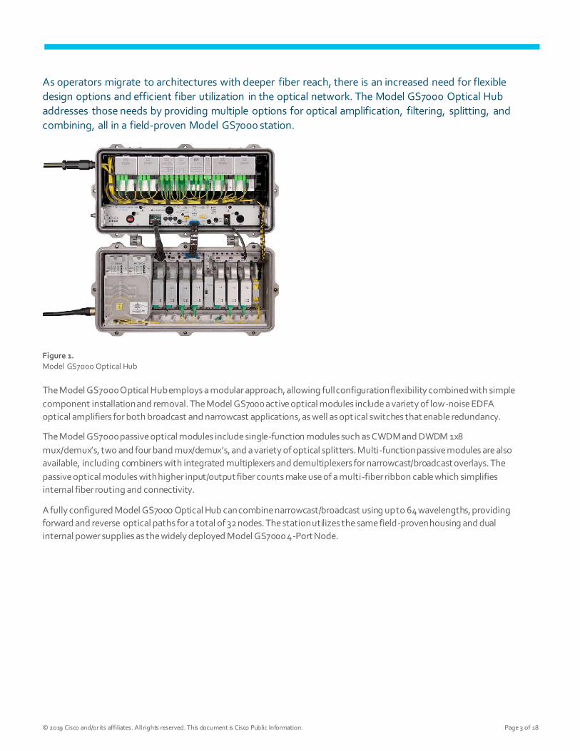
As operators migrate to architectures with deeper fiber reach, there is an increased need for flexible
design options and efficient fiber utilization in the optical network. The Model GS7000 Optical Hub
addresses those needs by providing multiple options for optical amplification, filtering, splitting, and
combining, all in a field-proven Model GS7000 station.
Figure 1.
Model GS7000 Optical Hub
The Model GS7000 Optical Hub employs a modular approach, allowing full configuration flexibility combined with simple
component installation and removal. The Model GS7000 active optical modules include a variety of low-noise EDFA
optical amplifiers for both broadcast and narrowcast applications, as well as opt ical switches that enable redundancy.
The Model GS7000 passive optical modules include single-function modules such as CWDM and DWDM 1x8
mux/demux’s, two and four band mux/demux’s, and a variety of optical splitters. Multi-function passive modules are also
available, including combiners with integrated multiplexers and demultiplexers for narrowcast/broadcast overlays. The
passive optical modules with higher input/output fiber counts make use of a multi-fiber ribbon cable which simplifies
internal fiber routing and connectivity.
A fully configured Model GS7000 Optical Hub can combine narrowcast/broadcast using up to 64 wavelengths, providing
forward and reverse optical paths for a total of 32 nodes. The station utilizes the same field-proven housing and dual
internal power supplies as the widely deployed Model GS7000 4-Port Node.

© 2019 Cisco and/or its affiliates. All rights reserved. This document is Cisco Public Information. Page 4 of 18
Features
● EDFA modules for optical amplification
● Optical switch modules for redundancy
● Flexible and scalable optical passive modules
● Fiber management tray and tracks provide easy fiber routing and access to fiber connections
● Status monitor/Local control module for remote monitoring and control (Transmission Network Control System
[TNCS] or other compatible element management system required)
● Fiber entry ports on both ends of housing lid
● AC power entry ports on both ends of the housing base
● Primary and redundant power supplies with passive load sharing
● Dual/Split AC powering
Benefits
● Eliminates building costs and permitting issues for new “brick and mortar” hub locations.
● Reduces the need for new fiber installation.
● Fiber management and fiber coupling (mux/demux, etc.) are typically done at the headend or hub, or within
strand-mounted splice enclosures. This can now be done with the Model GS7000 Optical Hub.
● All passive devices are enclosed within the housing. No need for external splice enclosures.
● Optical amplification is typically done at the headend or hub, or with strand-mounted optical amplifiers. This can
now be done with the Model GS7000 Optical Hub.
● The ability to add redundancy, or enable network switching for survivability is typically done at the headend or
hub. This can now be done with the Model GS7000 Optical Hub.
© 2019 Cisco and/or its affiliates. All rights reserved. This document is Cisco Public Information. Page 5 of 18
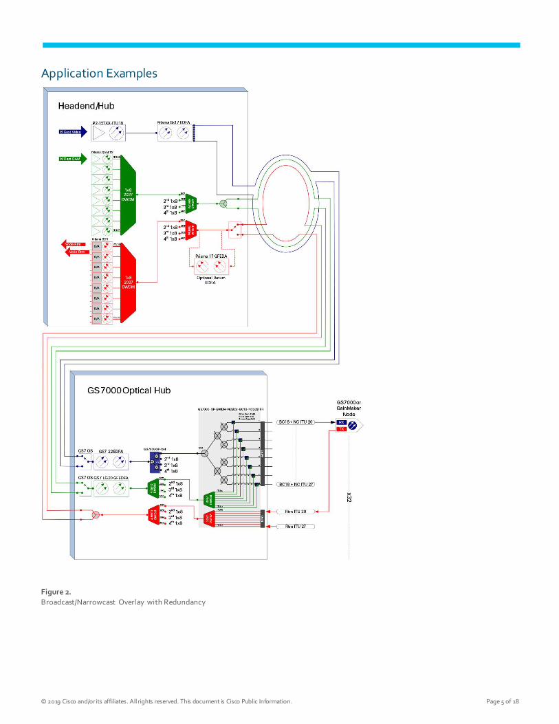
Application Examples
Figure 2.
Broadcast/Narrowcast Overlay with Redundancy
© 2019 Cisco and/or its affiliates. All rights reserved. This document is Cisco Public Information. Page 6 of 18
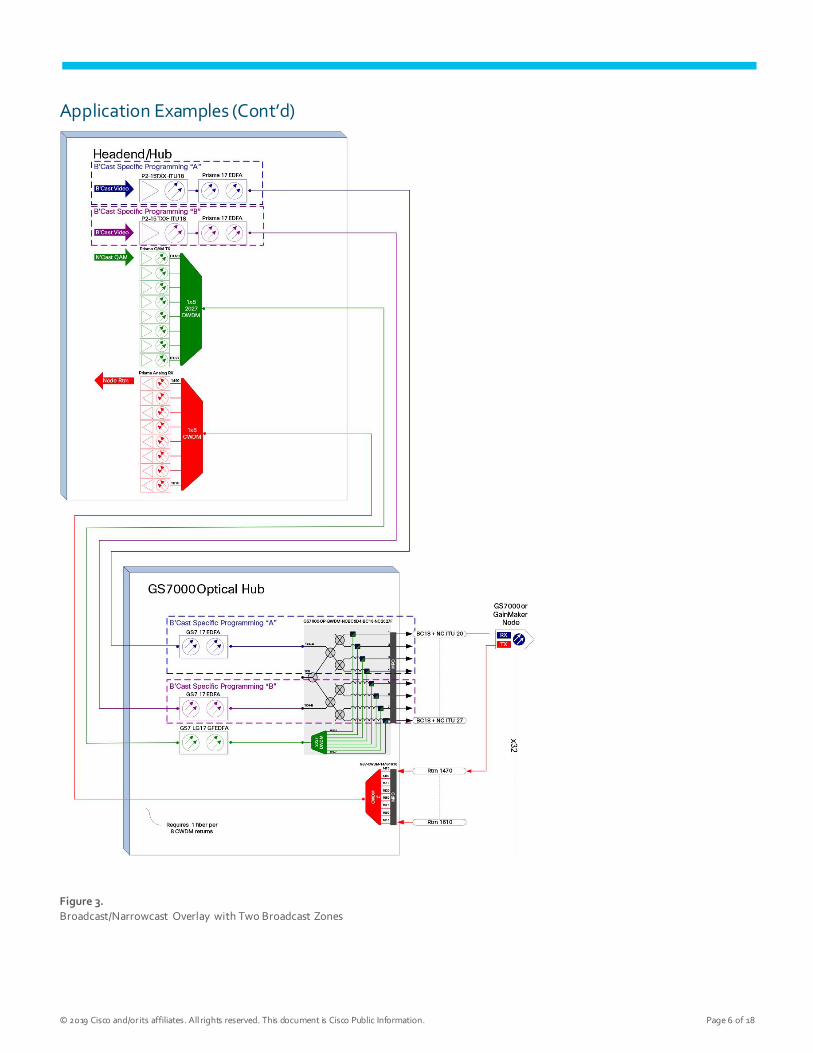
Application Examples (Cont’d)
Figure 3.
Broadcast/Narrowcast Overlay with Two Broadcast Zones
© 2019 Cisco and/or its affiliates. All rights reserved. This document is Cisco Public Information. Page 7 of 18
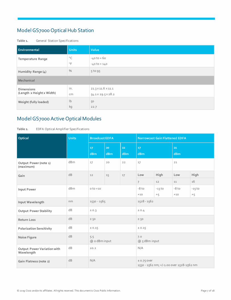
Model GS7000 Optical Hub Station
Table 1. General Station Specifications
Environmental Units Value
Temperature Range C
F
-40 to + 60
-40 to + 140
Humidity Range (4) % 5 to 95
Mechanical
Dimensions (Length x Height x Width)
in.
cm
21.3 x 11.6 x 11.1
54.1 x 29.5 x 28.2
Weight (fully loaded) lb
kg
50
22.7
Model GS7000 Active Optical Modules
Table 2. EDFA Optical Amplifier Specifications
Optical Units Broadcast EDFA Narrowcast Gain Flattened EDFA
17
dBm
20
dBm
22
dBm
17
dBm
21
dBm
Output Power (note 1) (maximum)
dBm 17 20 22 17 21
Gain dB 12 15 17 Low High Low High
7 12 11 16
Input Power dBm 0 to +10 -8 to
+10
-13 to
+5
-8 to
+10
-15 to
+5
Input Wavelength nm 1530 - 1565 1528 - 1562
Output Power Stability dB ± 0.3 ± 0.4
Return Loss dB ≥ 50 ≥ 50
Polarization Sensitivity dB ± 0.15 ± 0.15
Noise Figure dB 5.5
@ 0 dBm input
7.0
@ 5 dBm input
Output Power Variation with Wavelength
dB ±0.2 N/A
Gain Flatness (note 2) dB N/A ± 0.75 over
1530 - 1562 nm; +/-1.00 over 1528-1562 nm
© 2019 Cisco and/or its affiliates. All rights reserved. This document is Cisco Public Information. Page 8 of 18
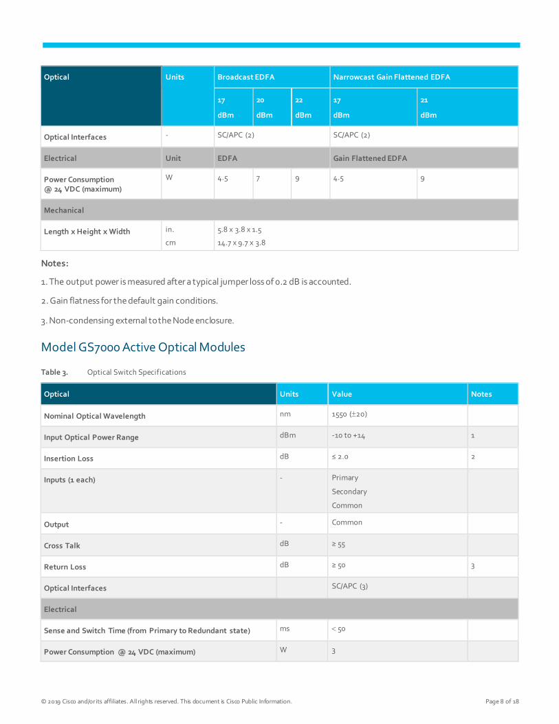
Optical Units Broadcast EDFA Narrowcast Gain Flattened EDFA
17
dBm
20
dBm
22
dBm
17
dBm
21
dBm
Optical Interfaces - SC/APC (2) SC/APC (2)
Electrical Unit EDFA Gain Flattened EDFA
Power Consumption @ 24 VDC (maximum)
W 4.5 7 9 4.5 9
Mechanical
Length x Height x Width in.
cm
5.8 x 3.8 x 1.5
14.7 x 9.7 x 3.8
Notes:
1. The output power is measured after a typical jumper loss of 0.2 dB is accounted.
2. Gain flatness for the default gain conditions.
3. Non-condensing external to the Node enclosure.
Model GS7000 Active Optical Modules
Table 3. Optical Switch Specifications
Optical Units Value Notes
Nominal Optical Wavelength nm 1550 (20)
Input Optical Power Range dBm -10 to +14 1
Insertion Loss dB ≤ 2.0 2
Inputs (1 each) - Primary
Secondary
Common
Output - Common
Cross Talk dB ≥ 55
Return Loss dB ≥ 50 3
Optical Interfaces SC/APC (3)
Electrical
Sense and Switch Time (from Primary to Redundant state) ms 50
Power Consumption @ 24 VDC (maximum) W 3
© 2019 Cisco and/or its affiliates. All rights reserved. This document is Cisco Public Information. Page 9 of 18
Optical Units Value Notes
Switching Threshold dB -10 to +14 (user changeable)
Restore Threshold dB 0.5 to 9.5
Wait Time before Restoration minutes 0 to 10 in 1 second steps
Mechanical
Length in.
cm
5.8
14.7
Width in.
cm
1.5
3.8
Height in.
cm
3.8
9.7
Weight lb
kg
.72
.33
Notes:
1. Optical input power of -3.0 dBm or greater is required to maintain the full user-settable threshold range. When the
optical input power is less than -3.0 dBm there is a 1-for-1 reduction in threshold range.
2. Insertion loss of module with 0.25 dB loss per mated connector pair for a total connector loss of 0.5 dB. Actual
connection loss may be less or more depending on mating connector compatibility.
3. With APC connectors.
Model GS7000 Passive Optical Modules
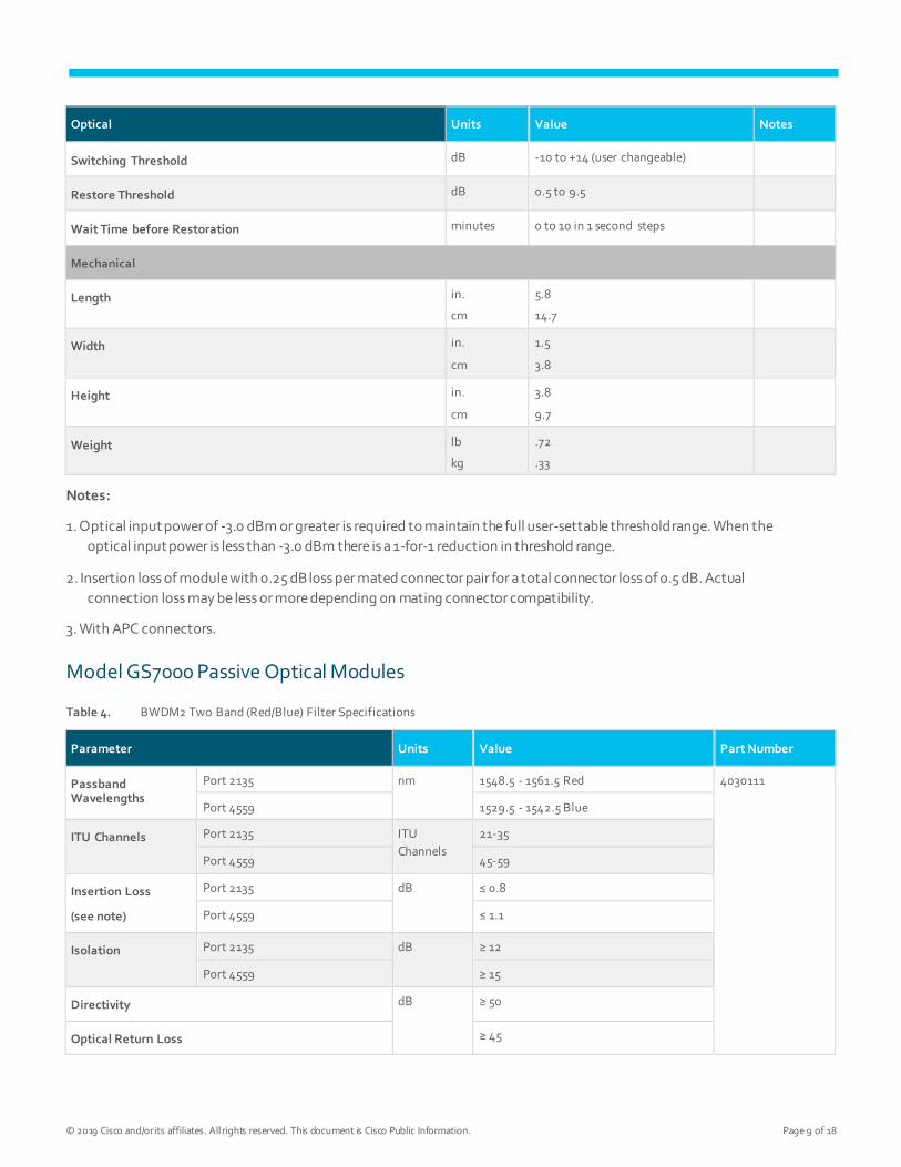
Table 4. BWDM2 Two Band (Red/Blue) Filter Specifications
Parameter Units Value Part Number
Passband Wavelengths
Port 2135 nm 1548.5 - 1561.5 Red 4030111
Port 4559 1529.5 - 1542.5 Blue
ITU Channels Port 2135 ITU
Channels
21-35
Port 4559 45-59
Insertion Loss
(see note)
Port 2135 dB ≤ 0.8
Port 4559 ≤ 1.1
Isolation Port 2135 dB ≥ 12
Port 4559 ≥ 15
Directivity dB ≥ 50
Optical Return Loss ≥ 45
© 2019 Cisco and/or its affiliates. All rights reserved. This document is Cisco Public Information. Page 10 of 18
Parameter Units Value Part Number
Optical Interfaces SC/APC (3)
Package 1 Wide Module
Note: Insertion loss includes input and output connector loss.
Figure 4.
BWDM2 Filter
Model GS7000 Passive Optical Modules
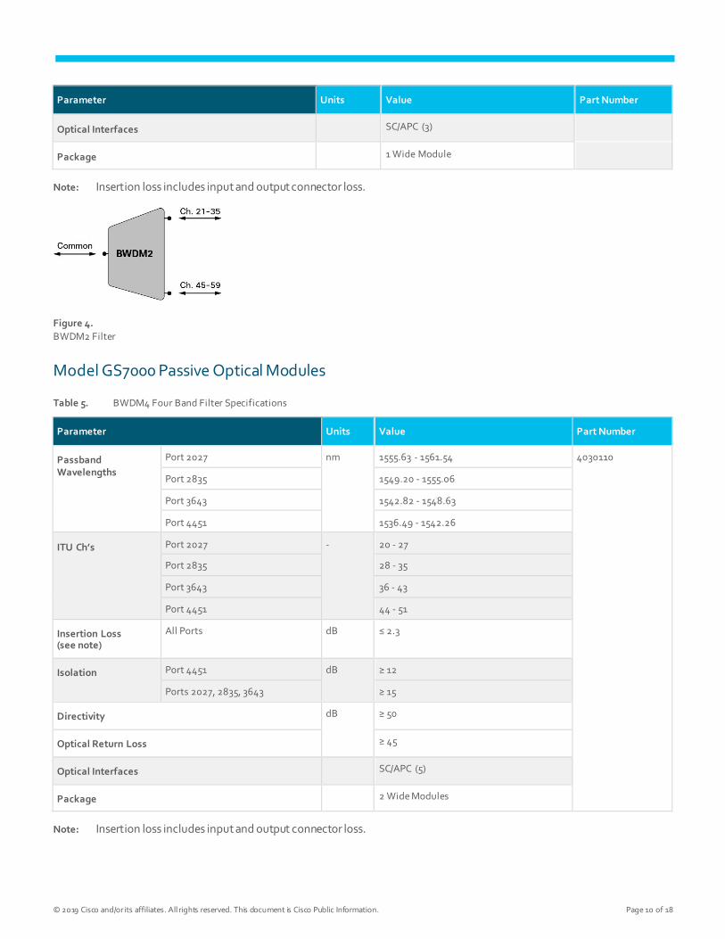
Table 5. BWDM4 Four Band Filter Specifications
Parameter Units Value Part Number
Passband Wavelengths
Port 2027 nm 1555.63 - 1561.54 4030110
Port 2835 1549.20 - 1555.06
Port 3643 1542.82 - 1548.63
Port 4451 1536.49 - 1542.26
ITU Ch’s Port 2027 - 20 - 27
Port 2835 28 - 35
Port 3643 36 - 43
Port 4451 44 - 51
Insertion Loss (see note)
All Ports dB ≤ 2.3
Isolation Port 4451 dB ≥ 12
Ports 2027, 2835, 3643 ≥ 15
Directivity dB ≥ 50
Optical Return Loss ≥ 45
Optical Interfaces SC/APC (5)
Package 2 Wide Modules
Note: Insertion loss includes input and output connector loss.
© 2019 Cisco and/or its affiliates. All rights reserved. This document is Cisco Public Information. Page 11 of 18
Figure 5.
BWDM4 Filter
Model GS7000 Passive Optical Modules
Table 6. Coupler Specifications
Configuration Parameter Units Value Part Number
Common Specifications
Wavelength nm 1550 ± 40
Split Ratio - Even
Optical Return Loss dB ≥ 55
1x2 Insertion Loss (note 1) dB ≤ 4.2 4030112
Uniformity dB 0.7
Optical Interfaces SC/APC (3)
Package 1 Wide Module
1x3 Insertion Loss (note 1) dB ≤ 6.3 4030113
Uniformity dB 1.0
Optical Interfaces SC/APC (4)
Package 2 Wide Modules
1x4 Insertion Loss (note 1) dB ≤ 7.6 4030114
Uniformity dB 1.2
Optical Interfaces SC/APC (5)
Package 2 Wide Modules
Note:
1. Insertion loss includes input and output connector loss.
© 2019 Cisco and/or its affiliates. All rights reserved. This document is Cisco Public Information. Page 12 of 18
Model GS7000 Passive Optical Modules
Table 7. DWDM or CWDM 8 Channel Mux/Demux Specifications
Configuration Parameter Units Value Part Number
DWDM 1x8 200G ITU Channels - 200 GHz spacing, Ch 21 - 35, ODD 4030093
200 GHz spacing, Ch 45 - 59, ODD 4030094
Channel Bandwidth @ 0.5 dB nm ± 0.25
Insertion Loss (see note) dB ≤ 3.0
DWDM 1x8 100G ITU Ch’s - 100 GHz spacing, Ch 20 - 27 4030096
100 GHz spacing, Ch 28 - 35 4030097
Channel Bandwidth @ 0.5 dB nm ± 0.12
Insertion Loss (note 1) dB ≤ 3.2
Common Specifications
Insertion Loss Uniformity dB 1.0
Polarization Dependent Loss
(PDL)
dB ≤ 0.2
Polarization Mode Dispersion
(PMD)
ps ≤ 0.15
Directivity dB ≥ 55
Optical Return Loss - All ports dB ≥ 50
Isolation dB ≥ 30 Adjacent Channels
≥ 40 Non-Adjacent Channels
Optical Interfaces 8 Fiber MPO with male guide pins APC (1)
SC/APC (1)
Package 2 Wide Modules
Note: Insertion loss includes input and output connector loss.
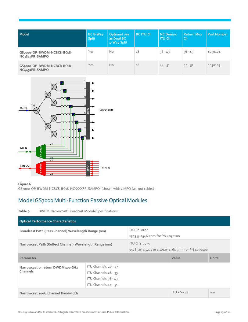
Model GS7000 Multi-Function Passive Optical Modules
Table 8. BWDM Narrowcast Broadcast with Narrowcast DeMux and Return Mux Specifications
Model BC 8-Way Split
Optional use as Dual BC 4-Way Split
BC ITU Ch NC Demux ITU Ch
Return Mux Ch
Part Number
GS7000-OP-BWDM-NCBC8-BC18-NC2027FR-SAMPO
Yes No 18 20 - 27 20 - 27 4030102
GS7000-OP-BWDM-NCBC8-BC18-NC2835FR-SAMPO
Yes No 18 28 - 35 28 - 35 4030103
© 2019 Cisco and/or its affiliates. All rights reserved. This document is Cisco Public Information. Page 13 of 18
Model BC 8-Way Split
Optional use as Dual BC 4-Way Split
BC ITU Ch NC Demux ITU Ch
Return Mux Ch
Part Number
GS7000-OP-BWDM-NCBC8-BC18-NC3643FR-SAMPO
Yes No 18 36 - 43 36 - 43 4030104
GS7000-OP-BWDM-NCBC8-BC18-NC4451FR-SAMPO
Yes No 18 44 - 51 44 - 51 4030105
Figure 6.
GS7000-OP-BWDM-NCBC8-BC18-NCXXXXFR-SAMPO (shown with 2 MPO fan-out cables)
Model GS7000 Multi-Function Passive Optical Modules
Table 9. BWDM Narrowcast Broadcast Module Specifications
Optical Performance Characteristics
Broadcast Path (Pass Channel) Wavelength Range (nm) ITU Ch 18 or
1543.5~1546.4nm for PN 4030100
Narrowcast Path (Reflect Channel) Wavelength Range (nm) ITU Ch’s 20-59
1528.50~1541.7 or 1549.0~1561.9nm for PN 4030100
Parameter Value Units
Narrowcast or return DWDM 100 GHz Channels
ITU Channels 20 - 27
ITU Channels 28 - 35
ITU Channels 36 - 43
ITU Channels 44 - 51
Narrowcast 100G Channel Bandwidth ITU +/-0.12 nm
© 2019 Cisco and/or its affiliates. All rights reserved. This document is Cisco Public Information. Page 14 of 18
Optical Performance Characteristics
Broadcast Path Insertion Loss (note 1)
Broadcast to Common Output 1 - 8 ≤ 12.0 dB
Broadcast to Common output 1 - 4 or 5 - 8 (only in
BCNC8D4 module)
≤ 9.0
Narrowcast Fwd Path Insertion Loss (note 1)
Narrowcast to Common Output ≤ 4.0 dB
Narrowcast to Common Output (only in part 4030100
and 4030101)
≤ 1.0
Return Path Insertion Loss (see note) Return port 1 - 8 to Common Output (only in NCBC8-
FR module)
≤ 3.0 dB
Passband Ripple ≤ 0.8 dB
Uniformity Across Common Outputs 2.5 dB
Uniformity Across Outputs for Return Mux 1.0 dB
Narrowcast or Return 100G Channel Isolation
Narrowcast to Broadcast ≥ 15 dB
Broadcast to Narrowcast ≥ 15 dB
Return Loss ≥ 45 dB
Directivity Narrowcast to Broadcast ≥ 55 dB
Optical Interfaces 8 Fiber MPO with male
guide pins APC
SC/APC
Package 3 Wide Package
Note: Insertion loss includes input and output connector loss.
Status Monitor Transponder/Local Control Modules
Overview
A Local Control Module must be installed to allow local monitoring and control of the active modules in the Model
GS7000 Optical Hub. For remote monitoring and control, a Status Monitor Transponder must also be installed. The Status
Monitor (SM) Transponder connects directly to the Local Control Module (LCM).
Local Control Module
The LCM provides local monitoring and control capability at the Model GS7000 Optical Hub station. The LCM is equipped
with a USB port to enable connection to a local PC/laptop. The Model GS7000 ViewPort software must be inst alled on the
PC/laptop to allow all parameters monitored by the LCM to be displayed and to allow local control of the optical switches
and optical amplifiers.
© 2019 Cisco and/or its affiliates. All rights reserved. This document is Cisco Public Information. Page 15 of 18
Status Monitor Transponder
The SM Transponder is HMS compliant and provides remote monitoring and control capability at the cable plant's
headend. The Model GS7000 Optical Hub must be connected to an active two-way RF network for status monitoring
communications. Configuration parameters for the transponder module, such as IP address, can be changed u sing the
PC-based ViewPort software.
Table 10. Monitorable Parameters (via LCM and SM Transponder)
Description
Station - AC power presence and peak voltage (for split AC powering cases, AC power from both sides of node housing is monitored)
Power Supply - DC voltages from both primary and redundant power supplies
EDFA Optical Amplifier - Input & Output Optical Power, Module Temperature
Optical Switch - Switch Position, Optical Power, Module Temperature
Table 11. Configurable Parameters (via LCM and SM Transponder)
Description
EDFA Optical Amplifier - Set Mode, Set Power, Set Gain, Enable
Optical Switch - Set Mode, Set Threshold, Set Switch Position
Model GS7000 Optical Hub Powering Information
Table 12. Station Powering Data
Electrical Units Value
Max AC Through Current (continuous) Amps 15
Max AC Through Current (surge)
Amps 25
Under-voltage Lockout Volts 33 VAC (no current draw below lockout voltage)
Component DC Current Draw (maximum)
@ +24 VDC @ +8 VDC @ +5 VDC @ -6 VDC
BC EDFA +17 dBm Amps 0.19 - - -
BC EDFA +20 dBm Amps 0.29 - - -
BC EDFA +22 dBm Amps 0.38 - - -
NC Gain-Flattened EDFA +17 dBm Amps 0.19 - - -
NC Gain-Flattened EDFA +21 dBm Amps 0.35 - - -
Optical Switch Amps 0.08 - - -
LCM/Status Monitoring Amps - - 0.5 -
© 2019 Cisco and/or its affiliates. All rights reserved. This document is Cisco Public Information. Page 16 of 18
Electrical Units Value
Power Supply DC Current Rating Amps 6.2 1.0 1.3 0.8
Optical Hub with: (1) 20 dBm BC EDFA, (1) 17 dBm NC Gain-Flattened EDFA, (2) Optical Switches, (1) LCM
DC Current 0.6 Amps @ 24 VDC and 0.5 Amps @ 5 VDC
AC Voltage 90 80 70 60 50 40
AC Current (A) 0.49 0.49 0.48 0.50 0.54 0.59
AC Power (W) 25.4 25.1 24.9 24.5 24.6 24.5
Optical Hub with: (2) 22 dBm BC EDFAs, (2) 21 dBm NC Gain-Flattened EDFAs, (2) Optical Switches, (1) LCM
DC Current 1.6 Amps @ 24 VDC and 0.5 Amps @ 5 VDC
AC Voltage 90 80 70 60 50 40
AC Current (A) 0.83 0.80 0.83 0.90 1.06 1.17
AC Power (W) 50.5 50.2 50.0 49.8 50.1 50.2
Optical Hub with: (7) 22 dBm BC EDFAs, (1) LCM
DC Current 2.6 Amps @ 24 VDC and 0.5 Amps @ 5 VDC
AC Voltage 90 80 70 60 50 40
AC Current (A) 1.19 1.18 1.26 1.43 1.64 1.83
AC Power (W) 81.5 80.9 80.9 80.8 78.1 78.2
Note: AC currents specified are based on measurements made with typical CATV type ferro-resonant AC power supply
(quasi-square wave).
Ordering Information
The Model GS7000 Optical Hub is available in a wide variety of configurations. The Model GS7000 Optical Hub ordering
matrix provides ordering information for configured node stations. This page contains ordering information for required
and optional accessories. Please consult with your Account Representative, Customer Service Representative, or Systems
Engineer to determine the best configuration for your particular application.
Table 13. Active Optical Modules
Description Part Number for Ordering
+17 dBm EDFA Broadcast 4027007
+20 dBm EDFA Broadcast 4027008
+22 dBm EDFA Broadcast 4027009
+17 dBm EDFA Gain Flattened, Low Gain GS7K-GFEDFA-17L=
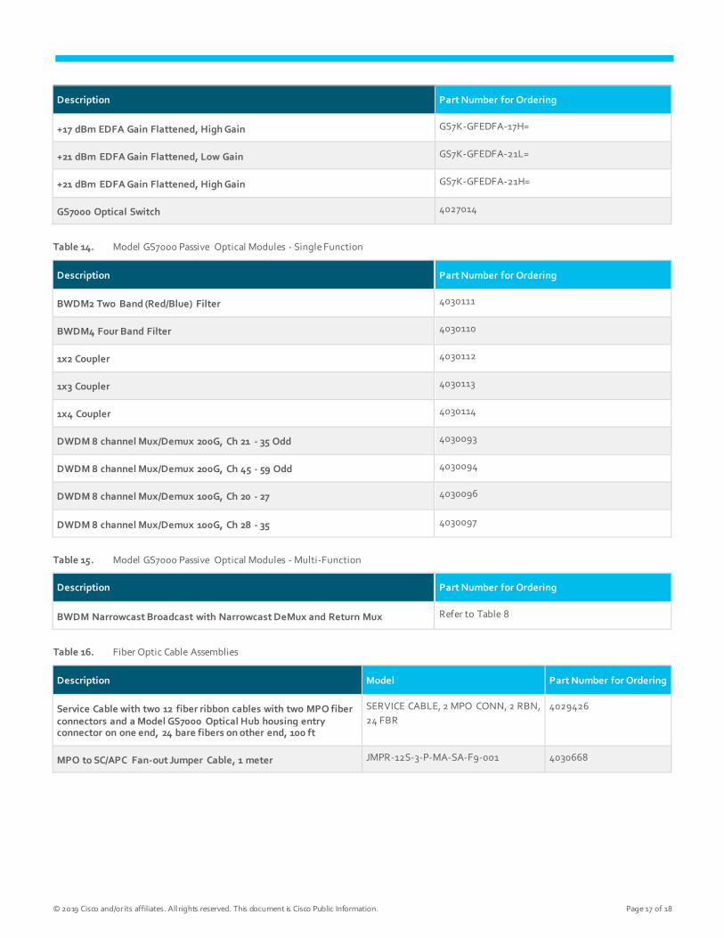
© 2019 Cisco and/or its affiliates. All rights reserved. This document is Cisco Public Information. Page 17 of 18
Description Part Number for Ordering
+17 dBm EDFA Gain Flattened, High Gain GS7K-GFEDFA-17H=
+21 dBm EDFA Gain Flattened, Low Gain GS7K-GFEDFA-21L=
+21 dBm EDFA Gain Flattened, High Gain GS7K-GFEDFA-21H=
GS7000 Optical Switch 4027014
Table 14. Model GS7000 Passive Optical Modules - Single Function
Description Part Number for Ordering
BWDM2 Two Band (Red/Blue) Filter 4030111
BWDM4 Four Band Filter 4030110
1x2 Coupler 4030112
1x3 Coupler 4030113
1x4 Coupler 4030114
DWDM 8 channel Mux/Demux 200G, Ch 21 - 35 Odd 4030093
DWDM 8 channel Mux/Demux 200G, Ch 45 - 59 Odd 4030094
DWDM 8 channel Mux/Demux 100G, Ch 20 - 27 4030096
DWDM 8 channel Mux/Demux 100G, Ch 28 - 35 4030097
Table 15. Model GS7000 Passive Optical Modules - Multi-Function
Description Part Number for Ordering
BWDM Narrowcast Broadcast with Narrowcast DeMux and Return Mux Refer to Table 8
Table 16. Fiber Optic Cable Assemblies
Description Model Part Number for Ordering
Service Cable with two 12 fiber ribbon cables with two MPO fiber connectors and a Model GS7000 Optical Hub housing entry connector on one end, 24 bare fibers on other end, 100 ft
SERVICE CABLE, 2 MPO CONN, 2 RBN,
24 FBR
4029426
MPO to SC/APC Fan-out Jumper Cable, 1 meter JMPR-12S-3-P-MA-SA-F9-001 4030668

© 2019 Cisco and/or its affiliates. All rights reserved. This document is Cisco Public Information. Page 18 of 18
Description Model Part Number for Ordering
SCA-SCA Jumper Cable, bend-insensitive, 1 meter JMPR-SSB-1.6-S-SA-SA-001 4030479
SCA-SCA Jumper Cable, bend-insensitive, 0.5 meter JMPR-SSB-1.6-S-SA-SA-0.5 4030476
Table 17. Other Model GS7000 Optical Hub Components
Description Part Number on Module Part Number for Ordering
Kit, GS7000 Optical Hub Housing Assembly (with 2 Power Supplies & Std Fiber Tray)
4025879
Kit, GS7000 Optical Hub Housing Assembly (with 2 Power Supplies & Ext Fiber Tray)
4040222
Power Supply 4009226 4011930
Local Control Module (LCM) no SM Transponder 4027113 4027114
Status Monitor Transponder (DOCSIS®) 4036793
Cisco Capital
Flexible Payment Solutions to Help you Achieve your Objectives
Cisco Capital makes it easier to get the right technology to achieve your objectives, enable business transformation
and help you stay competitive. We can help you reduce the total cost of ownership, conserve capital, and accelerate
growth. In more than 100 countries, our flexible payment solutions can help you acquire hardware, software, services and
complementary third-party equipment in easy, predictable payments. Learn more.
Printed in USAs C78-729512-01 07/19