Embed Size (px)
Citation preview

OL-29936-01
Model GS7000 Optical Hub
Installation and Configuration Guide


For Your Safety
Explanation of Warning and Caution Icons
Avoid personal injury and product damage! Do not proceed beyond any symbol until you fully understand the indicated conditions.
The following warning and caution icons alert you to important information about the safe operation of this product:
You may find this symbol in the document that accompanies this product. This symbol indicates important operating or maintenance instructions.
You may find this symbol affixed to the product. This symbol indicates a live terminal where a dangerous voltage may be present; the tip of the flash points to the terminal device.
You may find this symbol affixed to the product. This symbol indicates a protective ground terminal.
You may find this symbol affixed to the product. This symbol indicates a chassis terminal (normally used for equipotential bonding).
You may find this symbol affixed to the product. This symbol warns of a potentially hot surface.
You may find this symbol affixed to the product and in this document. This symbol indicates an infrared laser that transmits intensity-modulated light and emits invisible laser radiation or an LED that transmits intensity-modulated light.
Important
Please read this entire guide. If this guide provides installation or operation instructions, give particular attention to all safety statements included in this guide.

Notices
Trademark Acknowledgments
Cisco and the Cisco logo are trademarks or registered trademarks of Cisco and/or its affiliates in the U.S. and other countries. To view a list of Cisco trademarks, go to this URL: www.cisco.com/go/trademarks.
Third party trademarks mentioned are the property of their respective owners.
The use of the word partner does not imply a partnership relationship between Cisco and any other company. (1110R)
Publication Disclaimer
Cisco Systems, Inc. assumes no responsibility for errors or omissions that may appear in this publication. We reserve the right to change this publication at any time without notice. This document is not to be construed as conferring by implication, estoppel, or otherwise any license or right under any copyright or patent, whether or not the use of any information in this document employs an invention claimed in any existing or later issued patent.
Copyright
© 2009, 2013 Cisco and/or its affiliates. All rights reserved.
Information in this publication is subject to change without notice. No part of this publication may be reproduced or transmitted in any form, by photocopy, microfilm, xerography, or any other means, or incorporated into any information retrieval system, electronic or mechanical, for any purpose, without the express permission of Cisco Systems, Inc.

OL-29936-01 iii
Contents
Important Safety Instructions vii
Laser Safety xv
Laser Warning Labels xvii
Chapter 1 General Information 1
Equipment Description ........................................................................................................... 2 Overview ...................................................................................................................... 2 Physical Description ................................................................................................... 2 Functional Description ............................................................................................... 4 Features and Benefits ................................................................................................. 5 Housing Inputs/Outputs Diagram .......................................................................... 6 Modules Functional Descriptions ............................................................................. 7 Model Number Matrix ............................................................................................... 9
Chapter 2 Installation 11
Tools and Test Equipment .................................................................................................... 12 Required Tools and Test Equipment ...................................................................... 12 Node Fastener Torque Specifications ..................................................................... 12
Housing Ports ......................................................................................................................... 14 Strand Mounting .................................................................................................................... 15
Description ................................................................................................................. 15 Procedure ................................................................................................................... 15
Pedestal or Wall Mounting ................................................................................................... 18 Description ................................................................................................................. 18 Procedure ................................................................................................................... 18
Housing Lid Fiber Optic Cable Installation - Active Modules ........................................ 20 Overview .................................................................................................................... 20 FSC Color Code and Assignment ........................................................................... 20 Fiber Management System ...................................................................................... 21 Procedure ................................................................................................................... 23
Housing Base Fiber Optic Cable Installation - Passive Modules .................................... 28 Overview .................................................................................................................... 28 MPO FSC Color Code and Assignment ................................................................. 28 Fiber Management System ...................................................................................... 29 Procedure ................................................................................................................... 29

Contents
iv OL-29936-01
Fiber Optic Connections - Active to Passive Modules ...................................................... 33 Overview .................................................................................................................... 33 Fiber Management System ...................................................................................... 33 Procedure ................................................................................................................... 34
RF Cable Installation ............................................................................................................. 37 Overview .................................................................................................................... 37 Trimming the Center Conductor ............................................................................ 37 Connecting the RF Cables to the Housing ............................................................ 39
Applying Power to the Hub ................................................................................................. 40 Overview .................................................................................................................... 40 Hub Powering Procedure ........................................................................................ 40 Voltage Check Procedure ........................................................................................ 42
Chapter 3 Setup and Operation 43
Tools and Test Equipment .................................................................................................... 44 Required Tools and Test Equipment ...................................................................... 44
AC Entry Module ................................................................................................................... 45 AC Powering ............................................................................................................. 45 RF Section ................................................................................................................... 45
Optical Passive Modules ....................................................................................................... 46 NCBC Combiners without Multiplexers/Demultiplexers ................................. 46 NCBC Combiners with Integrated Forward Demux and Return Mux ............. 47 NCBC Combiners with Forward Demux .............................................................. 48 DWDM and CWDM 1x8 .......................................................................................... 49 1x2, 1x3, 1x4 Couplers .............................................................................................. 50 1x8 Dual 1x4 Coupler ............................................................................................... 51 BWDM 1x2 Red/Blue and 1x4 Filters .................................................................... 52
Optical Amplifier (EDFA) Modules .................................................................................... 53 Optical Amplifier Module Descriptions ................................................................ 53 Optical Amplifier Module Models ......................................................................... 54 Optical Amplifier Module Diagram ....................................................................... 55 Optical Amplifier Operating Parameters .............................................................. 55 Broadcast EDFA Power and Gain Setup ............................................................... 59 Narrowcast EDFA Power and Gain Setup ............................................................ 61
Optical Amplifier Power In and Power Out Test Point Use and Operation ................. 70 Power In Measurement ............................................................................................ 70 Power Out Measurement ......................................................................................... 71
Optical Switch Module .......................................................................................................... 72 Optical Switch Module Description ....................................................................... 72 Optical Switch Module Diagram ............................................................................ 73 Optical Switch Operating Parameters ................................................................... 74
Status Monitor/Local Control Module ............................................................................... 77 Overview .................................................................................................................... 77 Status Monitor Description ..................................................................................... 77 Local Control Module Description ......................................................................... 78

Contents
OL-29936-01 v
Power Supply Module .......................................................................................................... 80 Introduction ............................................................................................................... 80 Power Supply Module Description ........................................................................ 80 Power Distribution ................................................................................................... 82
Hub Architecture Examples ................................................................................................. 84 Broadcast/Narrowcast Overlay with Redundancy ............................................. 85 Broadcast/Narrowcast Overlay with Two Broadcast Zones ............................. 89
Chapter 4 Maintenance 93
Opening and Closing the Housing ...................................................................................... 94 Overview .................................................................................................................... 94 Opening the Housing ............................................................................................... 94 Closing the Housing ................................................................................................. 94
Preventative Maintenance .................................................................................................... 96 Overview .................................................................................................................... 96 Schedule ..................................................................................................................... 96 Visual Inspection ....................................................................................................... 96 Cleaning ..................................................................................................................... 97 Consumable Materials ............................................................................................. 97 Procedure ................................................................................................................... 97
Removing and Replacing Modules ..................................................................................... 99 Overview .................................................................................................................... 99 Module Replacement Procedure - Active Modules ............................................. 99 Module Replacement Procedure - Passive Modules ......................................... 101
Care and Cleaning of Optical Connectors ........................................................................ 103 Recommended Equipment .................................................................................... 103 Tips for Optimal Fiber Optic Connector Performance ...................................... 103 To Clean Optical Connectors ................................................................................ 104
Chapter 5 Customer Information 107
Appendix A Technical Information 109
Model GS7000 Optical Hub Accessory Part Numbers ................................................... 110 Attenuators .............................................................................................................. 110
Torque Specifications .......................................................................................................... 112 Node Fastener Torque Specifications ................................................................... 112
Appendix B Expanded Fiber Tray 113
Expanded Fiber Tray Overview......................................................................................... 114 Introduction ............................................................................................................. 114 Features .................................................................................................................... 114 Tray Components ................................................................................................... 115

Contents
vi OL-29936-01
Expanded Fiber Tray Installation ...................................................................................... 116 Installation Procedure ............................................................................................ 116
Fiber Management System ................................................................................................. 119 Overview .................................................................................................................. 119 Maintaining Fiber Bend Radius ............................................................................ 119 Proper Fiber Routing .............................................................................................. 120 Connector and Bulkhead Access .......................................................................... 121 Fiber Protection ....................................................................................................... 121 Passive Device and Bulkhead Mounting ............................................................. 122 Fiber Installation ..................................................................................................... 124
Glossary 125
Index 135

Important Safety Instructions
OL-29936-01 vii
Important Safety Instructions Read these instructions. Keep these instructions. Heed all warnings. Follow all instructions. Only use attachments/accessories specified by the manufacturer.
Read and Retain Instructions
Carefully read all safety and operating instructions before operating this equipment, and retain them for future reference.
Follow Instructions and Heed Warnings
Follow all operating and use instructions. Pay attention to all warnings and cautions in the operating instructions, as well as those that are affixed to this equipment.
Terminology
The terms defined below are used in this document. The definitions given are based on those found in safety standards.
Service Personnel - The term service personnel applies to trained and qualified individuals who are allowed to install, replace, or service electrical equipment. The service personnel are expected to use their experience and technical skills to avoid possible injury to themselves and others due to hazards that exist in service and restricted access areas.
User and Operator - The terms user and operator apply to persons other than service personnel.
Ground(ing) and Earth(ing) - The terms ground(ing) and earth(ing) are synonymous. This document uses ground(ing) for clarity, but it can be interpreted as having the same meaning as earth(ing).
Electric Shock Hazard
This equipment meets applicable safety standards.
WARNING:
To reduce risk of electric shock, perform only the instructions that are included in the operating instructions. Refer all servicing to qualified service personnel only.
Electric shock can cause personal injury or even death. Avoid direct contact with dangerous voltages at all times.

Important Safety Instructions
viii OL-29936-01
Know the following safety warnings and guidelines:
Only qualified service personnel are allowed to perform equipment installation or replacement.
Only qualified service personnel are allowed to remove chassis covers and access any of the components inside the chassis.
Equipment Placement
WARNING:
Avoid personal injury and damage to this equipment. An unstable mounting surface may cause this equipment to fall.
To protect against equipment damage or injury to personnel, comply with the following:
Install this equipment in a restricted access location (access restricted to service personnel).
Make sure the mounting surface or rack is stable and can support the size and weight of this equipment.
Strand (Aerial) Installation
CAUTION:
Be aware of the size and weight of strand-mounted equipment during the installation operation.
Ensure that the strand can safely support the equipment’s weight.
Pedestal, Service Closet, Equipment Room or Underground Vault Installation
WARNING:
Avoid the possibility of personal injury. Ensure proper handling/lifting techniques are employed when working in confined spaces with heavy equipment.
Ensure this equipment is securely fastened to the mounting surface or rack where necessary to protect against damage due to any disturbance and subsequent fall.
Ensure the mounting surface or rack is appropriately anchored according to manufacturer’s specifications.
Ensure the installation site meets the ventilation requirements given in the equipment’s data sheet to avoid the possibility of equipment overheating.

Important Safety Instructions
OL-29936-01 ix
Ensure the installation site and operating environment is compatible with the equipment’s International Protection (IP) rating specified in the equipment’s data sheet.
Connecting to Utility AC Power
Important: If this equipment is a Class I equipment, it must be grounded.
If this equipment plugs into an outlet, the outlet must be near this equipment, and must be easily accessible.
Connect this equipment only to the power sources that are identified on the equipment-rating label, which is normally located close to the power inlet connector(s).
This equipment may have two power sources. Be sure to disconnect all power sources before working on this equipment.
If this equipment does not have a main power switch, the power cord connector serves as the disconnect device.
Always pull on the plug or the connector to disconnect a cable. Never pull on the cable itself.
Connection to Network Power Sources
Refer to this equipment’s specific installation instructions in this manual or in companion manuals in this series for connection to network ferro-resonant AC power sources.
AC Power Shunts
AC power shunts may be provided with this equipment.
Important: The power shunts (where provided) must be removed before installing modules into a powered housing. With the shunts removed, power surge to the components and RF-connectors is reduced.
CAUTION:
RF connectors and housing seizure assemblies can be damaged if shunts are not removed from the equipment before installing or removing modules from the housing.
Grounding (Utility AC Powered Equipment in Pedestals, Service Closets, etc.)
This section provides instructions for verifying that the equipment is properly grounded.

Important Safety Instructions
x OL-29936-01
Safety Plugs (USA Only)
This equipment may be equipped with either a 3-terminal (grounding-type) safety plug or a 2-terminal (polarized) safety plug. The wide blade or the third terminal is provided for safety. Do not defeat the safety purpose of the grounding-type or polarized safety plug.
To properly ground this equipment, follow these safety guidelines:
Grounding-Type Plug - For a 3-terminal plug (one terminal on this plug is a protective grounding pin), insert the plug into a grounded mains, 3-terminal outlet.
Note: This plug fits only one way. If this plug cannot be fully inserted into the outlet, contact an electrician to replace the obsolete 3-terminal outlet.
Polarized Plug - For a 2-terminal plug (a polarized plug with one wide blade and one narrow blade), insert the plug into a polarized mains, 2-terminal outlet in which one socket is wider than the other.
Note: If this plug cannot be fully inserted into the outlet, try reversing the plug. If the plug still fails to fit, contact an electrician to replace the obsolete 2-terminal outlet.
Grounding Terminal
If this equipment is equipped with an external grounding terminal, attach one end of an 18-gauge wire (or larger) to the grounding terminal; then, attach the other end of the wire to a ground, such as a grounded equipment rack.
Safety Plugs (European Union)
Class I Mains Powered Equipment – Provided with a 3-terminal AC inlet and requires connection to a 3-terminal mains supply outlet via a 3-terminal power cord for proper connection to the protective ground.
Note: The equipotential bonding terminal provided on some equipment is not designed to function as a protective ground connection.
Class II Mains Powered Equipment – Provided with a 2-terminal AC inlet that may be connected by a 2-terminal power cord to the mains supply outlet. No connection to the protective ground is required as this class of equipment is provided with double or reinforced and/or supplementary insulation in addition to the basic insulation provided in Class I equipment.
Note: Class II equipment, which is subject to EN 50083-1, is provided with a chassis mounted equipotential bonding terminal. See the section titled Equipotential Bonding for connection instructions.

Important Safety Instructions
OL-29936-01 xi
Equipotential Bonding
If this equipment is equipped with an external chassis terminal marked with the IEC
60417-5020 chassis icon ( ), the installer should refer to CENELEC standard EN 50083-1 or IEC standard IEC 60728-11 for correct equipotential bonding connection instructions.
General Servicing Precautions
WARNING:
Avoid electric shock! Opening or removing this equipment’s cover may expose you to dangerous voltages.
CAUTION:
These servicing precautions are for the guidance of qualified service personnel only. To reduce the risk of electric shock, do not perform any servicing other than that contained in the operating instructions unless you are qualified to do so. Refer all servicing to qualified service personnel.
Be aware of the following general precautions and guidelines:
Servicing - Servicing is required when this equipment has been damaged in any way, such as power supply cord or plug is damaged, liquid has been spilled or objects have fallen into this equipment, this equipment has been exposed to rain or moisture, does not operate normally, or has been dropped.
Wristwatch and Jewelry - For personal safety and to avoid damage of this equipment during service and repair, do not wear electrically conducting objects such as a wristwatch or jewelry.
Lightning - Do not work on this equipment, or connect or disconnect cables, during periods of lightning.
Labels - Do not remove any warning labels. Replace damaged or illegible warning labels with new ones.
Covers - Do not open the cover of this equipment and attempt service unless instructed to do so in the instructions. Refer all servicing to qualified service personnel only.
Moisture - Do not allow moisture to enter this equipment.
Cleaning - Use a damp cloth for cleaning.
Safety Checks - After service, assemble this equipment and perform safety checks to ensure it is safe to use before putting it back into operation.

Important Safety Instructions
xii OL-29936-01
Electrostatic Discharge
Electrostatic discharge (ESD) results from the static electricity buildup on the human body and other objects. This static discharge can degrade components and cause failures.
Take the following precautions against electrostatic discharge:
Use an anti-static bench mat and a wrist strap or ankle strap designed to safely ground ESD potentials through a resistive element.
Keep components in their anti-static packaging until installed.
Avoid touching electronic components when installing a module.
Fuse Replacement
To replace a fuse, comply with the following:
Disconnect the power before changing fuses.
Identify and clear the condition that caused the original fuse failure.
Always use a fuse of the correct type and rating. The correct type and rating are indicated on this equipment.
Batteries
This product may contain batteries. Special instructions apply regarding the safe use and disposal of batteries:
Safety
Insert batteries correctly. There may be a risk of explosion if the batteries are incorrectly inserted.
Do not attempt to recharge ‘disposable’ or ‘non-reusable’ batteries.
Please follow instructions provided for charging ‘rechargeable’ batteries.
Replace batteries with the same or equivalent type recommended by manufacturer.
Do not expose batteries to temperatures above 100°C (212°F).
Disposal
The batteries may contain substances that could be harmful to the environment
Recycle or dispose of batteries in accordance with the battery manufacturer’s instructions and local/national disposal and recycling regulations.

Important Safety Instructions
OL-29936-01 xiii
The batteries may contain perchlorate, a known hazardous substance, so special handling and disposal of this product might be necessary. For more information about perchlorate and best management practices for perchlorate-containing substance, see www.dtsc.ca.gov/hazardouswaste/perchlorate.
Modifications
This equipment has been designed and tested to comply with applicable safety, laser safety, and EMC regulations, codes, and standards to ensure safe operation in its intended environment. Refer to this equipment's data sheet for details about regulatory compliance approvals.
Do not make modifications to this equipment. Any changes or modifications could void the user’s authority to operate this equipment.
Modifications have the potential to degrade the level of protection built into this equipment, putting people and property at risk of injury or damage. Those persons making any modifications expose themselves to the penalties arising from proven non-compliance with regulatory requirements and to civil litigation for compensation in respect of consequential damages or injury.
Accessories
Use only attachments or accessories specified by the manufacturer.
Electromagnetic Compatibility Regulatory Requirements
This equipment meets applicable electromagnetic compatibility (EMC) regulatory requirements. Refer to this equipment's data sheet for details about regulatory compliance approvals. EMC performance is dependent upon the use of correctly shielded cables of good quality for all external connections, except the power source, when installing this equipment.
Ensure compliance with cable/connector specifications and associated installation instructions where given elsewhere in this manual.
EMC Compliance Statements
Where this equipment is subject to USA FCC and/or Industry Canada rules, the following statements apply:

Important Safety Instructions
xiv OL-29936-01
FCC Statement for Class A Equipment
This equipment has been tested and found to comply with the limits for a Class A digital device, pursuant to Part 15 of the FCC Rules. These limits are designed to provide reasonable protection against harmful interference when this equipment is operated in a commercial environment.
This equipment generates, uses, and can radiate radio frequency energy and, if not installed and used in accordance with the instruction manual, may cause harmful interference to radio communications. Operation of this equipment in a residential area is likely to cause harmful interference in which case users will be required to correct the interference at their own expense.
Industry Canada - Industrie Canadiene Statement
This apparatus complies with Canadian ICES-003. Cet appareil est confome à la norme NMB-003 du Canada.
CENELEC/CISPR Statement with Respect to Class A Information Technology Equipment
This is a Class A equipment. In a domestic environment this equipment may cause radio interference in which case the user may be required to take adequate measures.

Laser Safety
OL-29936-01 xv
Laser Safety
Introduction
This equipment contains an infrared laser that transmits intensity-modulated light and emits invisible radiation.
Warning: Radiation
WARNING:
Avoid personal injury! Use of controls, adjustments, or procedures other than those specified herein may result in hazardous radiation exposure.
Avoid personal injury! The laser light source on this equipment (if a transmitter) or the fiber cables connected to this equipment emit invisible laser radiation. Avoid direct exposure to the laser light source.
Avoid personal injury! Viewing the laser output (if a transmitter) or fiber cable with optical instruments (such as eye loupes, magnifiers, or microscopes) may pose an eye hazard.
Do not apply power to this equipment if the fiber is unmated or unterminated.
Do not stare into an unmated fiber or at any mirror-like surface that could reflect light emitted from an unterminated fiber.
Do not view an activated fiber with optical instruments such as eye loupes, magnifiers, or microscopes.
Use safety-approved optical fiber cable to maintain compliance with applicable laser safety requirements.
Warning: Fiber Optic Cables
WARNING:
Avoid personal injury! Qualified service personnel may only perform the procedures in this manual. Wear safety glasses and use extreme caution when handling fiber optic cables, particularly during splicing or terminating operations. The thin glass fiber core at the center of the cable is fragile when exposed by the removal of cladding and buffer material. It easily fragments into glass splinters. Using tweezers, place splinters immediately in a sealed waste container and dispose of them safely in accordance with local regulations.

Laser Safety
xvi OL-29936-01
Safe Operation for Software Controlling Optical Transmission Equipment
If this manual discusses software, the software described is used to monitor and/or control ours and other vendors’ electrical and optical equipment designed to transmit video, voice, or data signals. Certain safety precautions must be observed when operating equipment of this nature.
For equipment specific safety requirements, refer to the appropriate section of the equipment documentation.
For safe operation of this software, refer to the following warnings.
WARNING:
Ensure that all optical connections are complete or terminated before using this equipment to remotely control a laser device. An optical or laser device can pose a hazard to remotely located personnel when operated without their knowledge.
Allow only personnel trained in laser safety to operate this software. Otherwise, injuries to personnel may occur.
Restrict access of this software to authorized personnel only.
Install this software in equipment that is located in a restricted access area.

Laser Warning Labels
OL-29936-01 xvii
Laser Warning Labels
Maximum Laser Power
The maximum laser power that can be expected from the EDFA optical amplifier for various amplifier configurations is defined in the following table.
Output Power
Maximum Output
CDRH Classification
IEC 60825-1 Classification
IEC 60825-2 Hazard Level
17 dBm 17 dBm 1 1M 1M
20 dBm 20 dBm 1 1M 1M
21 dBm 21 dBm 1 1M 3B
22 dBm 22 dBm 1 1M 3B
Warning Labels
One or more of the labels shown below are located on this product.

Laser Warning Labels
xviii OL-29936-01
Location of Labels on Equipment
The following illustrations display the location of warning labels on this equipment.

Laser Warning Labels
OL-29936-01 xix


OL-29936-01 1
Introduction
This manual describes the installation and operation of the Model GS7000 Optical Hub.
1 Chapter 1 General Information
In This Chapter
Equipment Description .......................................................................... 2

Chapter 1 General Information
2 OL-29936-01
Equipment Description
Overview
This section contains a physical and functional description of the Model GS7000 Optical Hub.
Physical Description
The Model GS7000 Optical Hub is an optical platform in a Model GS7000 Node housing. The housing has a hinged lid to allow access to the internal electrical and optical components. The housing also has provisions for strand, pedestal, or wall mounting.
The base of the housing contains:
Optical passive device tray (for installing multiplexers, demultiplexers, splitters, and combiners)
Fiber management track (for routing optical fiber)
AC entry module (for powering the hub)
The lid of the housing contains:
Fiber management tray and track (for routing optical fiber)
Optical interface board (OIB) (for mounting and interconnecting modules in lid)
EDFA (erbium-doped fiber amplifier) modules (for signal amplification)
Optical switch modules (for redundancy)
Status monitor/local control module (for remote monitoring and control)
Power supplies (one or two per housing)
Not every Model GS7000 Optical Hub will contain all of these modules.
The following illustration shows the external housing of the Model GS7000 Optical Hub.

Equipment Description
OL-29936-01 3
The following illustration shows the Model GS7000 Optical Hub internal modules and components.

Chapter 1 General Information
4 OL-29936-01
Functional Description
The GS7000 platform is a flexible hub node platform that enables operators to initially deploy the Model GS7000 Node and later migrate to either a hub node or a full optical hub. The GS7000 platform is one of the industry's most user-friendly platforms to migrate, and one of the most flexible platforms to meet all of your optical node and optical hub needs. You can easily scale services along with customer demand and generate more bandwidth for more customers as their need for more services increases.

Equipment Description
OL-29936-01 5
The Model GS7000 Node can be upgraded to a Model GS7000 Hub Node in the field. This is accomplished by the installation of optical amplification (EDFA) modules, optical switching modules, and the Status Monitor/Local Control Module in the node lid. The Model GS7000 Hub Node can then serve as a traditional node feeding the local HFC plant and as an optical hub with the optical amplifiers. The hub node with the amplifiers can service up to 32 nodes, each with dedicated narrowcasting forward and return wavelengths, with as few as three fibers.
EDFAs are available in 17 dBm, 20 dBm, and 22 dBm for broadcasting. A 17 dBm or 21 dBm gain flattened EDFA version is available to fit any architecture for requirements like DWDM narrowcasting. The optical switch module is used for switching the input of an EDFA module from a primary signal to a backup or secondary signal. The switch is monitored and controlled by the Status Monitor/Local Control Module (SM/LCM) in the node. A specific model of the SM/LCM is required for use in the optical hub. This SM/LCM model monitors and controls several EDFA and optical switch parameters and functions.
The Model GS7000 Hub Node can migrate to a full optical hub by replacing the RF amplifier section with an optical passive device tray which can accommodate various optical passive devices. The optical passive device tray has the capacity of housing four 1x8 narrowcast/broadcast overlay combiners with integrated multiplexers and demultiplexers. A four-band mux/demux, a 1x4 splitter, and a 1x2 splitter are also available. These modular passive devices provide effortless installation and removal, simple troubleshooting, and the capability to use off the shelf fiber jumpers to interconnect active and passive modules. A fully deployed Model GS7000 Optical Hub can be used to combine narrowcast/ broadcast up to 64 wavelengths feeding 32 nodes.
Features and Benefits
The Model GS7000 Optical Hub has the following features:
EDFA modules for optical amplification
Optical switch modules for redundancy
Flexible and scalable optical passive modules
Fiber management tray and tracks provides easy fiber routing and access to fiber connections
Status monitor/Local control module for remote monitoring and control (Transmission Network Control System [TNCS] or other compatible element management system required)
Fiber entry ports on both ends of housing lid
AC power entry ports on both ends of the housing base
Primary and redundant power supplies with passive load sharing
Dual/Split AC powering

Chapter 1 General Information
6 OL-29936-01
The Model GS7000 Optical Hub offers the following benefits:
Eliminates building costs and permitting issues for new "brick and mortar" hub locations.
Reduces the need for new fiber installation.
Fiber management and fiber coupling (mux/demux, etc.) are typically done at the headend or hub, or within strand-mounted splice enclosures. This can now be done with the Model GS7000 Optical Hub.
All passives devices are enclosed within the housing. No need for external splice enclosures.
Optical amplification is typically done at the headend or hub. This can now be done with the Model GS7000 Optical Hub.
The ability to add redundancy, or enable network switching for survivability, is typically done at the headend or hub. This can now be done with the Model GS7000 Optical Hub.
Housing Inputs/Outputs Diagram
The following diagram shows the housing port inputs and outputs for coaxial (COAX) and fiber service cables (FSC) of the Model GS7000 Optical Hub.
Note: Ports RF 1, RF 2, RF 4, and RF 5 (not shown) on the housing base are not used for COAX cable connections on the optical hub.
Note: The AC can be applied to port 3 or port 6.

Equipment Description
OL-29936-01 7
Modules Functional Descriptions
This table briefly describes each module. The Model GS7000 Optical Hub may not contain all these modules.
Module Description
Optical Amplifier (EDFA)
Erbium-doped fiber amplifier modules are available in two categories: broadcast and narrowcast. EDFAs are available in 17 dBm, 20 dBm, and 22 dBm (standard) for broadcasting. A 17 dBm or 21 dBm narrowcast constant gain EDFA version is available to fit any architecture for requirements like DWDM narrowcasting. EDFA modules are single-wide, single-output devices. The modules mount in slots 3 through 6 and 8 through 11 on the optical interface board in the housing lid. The EDFA is monitored and controlled by the Status Monitor/Local Control Module in the node.
Optical Switch The optical switch module is used for switching the input of an EDFA module from a primary signal to a backup or secondary signal. The module mounts in slots 3 through 6 and 8 through 11 on the optical interface board in the housing lid. The switch is monitored and controlled by the Status Monitor/Local Control Module in the node.
Status Monitor/ Local Control Module
(SM/LCM)
The local control module monitors the AC power entry and power supply DC voltage rails. It can be upgraded to a status monitor which provides monitoring and control capability at the cable plant's headend. In a hub application the SM/LCM monitors and controls the operation of the EDFAs and optical switches. The module mounts in slot 7 on the optical interface board in the housing lid.
Optical Interface Board
The Optical Interface Board (OIB) provides all interconnections between the modules in the housing lid of the Model GS7000 Optical Hub. The modules in the housing lid include the EDFAs, optical switches, power supplies, and status monitoring/local control modules. Each module in the lid plugs directly into the OIB through a connector header or row of sockets. All RF and power cables running between the housing lid and base also plug into the OIB.
AC Entry Module The AC entry module is the hub's power entry and power passing module. AC power enters the module via ports 3 or 6 on the housing. The module is capable of passing power or providing redundant powering depending on which shunts are installed. It powers both DC power supplies and passes information regarding power to the status monitor in the housing lid via a molded RF cable assembly.

Chapter 1 General Information
8 OL-29936-01
Module Description
Power Supply The power supply module has multiple output voltages of +24.5, +8.5, -6.0, and +5.5 VDC. A second power supply can be installed in the housing for redundancy or load sharing.
The Model GS7000 Optical Hub can be set up in the following powering configurations:
two power supplies powered by different AC sources
two power supplies using the same AC source
a single supply using a single AC source
Optical Passive Devices
Various optical passive devices are available to support different network configurations. For example:
1x8 NCBC overlay combiners with integrated multiplexers/demultiplexers
four-band multiplexer/demultiplexer
1x4, 1x3, and 1x2 splitters
Optical Passives Tray
The optical passives tray provides simple installation of passive modules in the housing base.
Fiber Management Tray and Tracks
The fiber management system secures and protects the optical fibers as they are routed inside the housing.
Fiber Slack Spool The fiber slack spool mounts in slot 11 of the optical interface board in the housing lid. It serves as a pathway for routing optical fibers between modules the housing lid and base.

Equipment Description
OL-29936-01 9
Model Number Matrix
The Model GS7000 Optical Hub is capable of many configurations to fill various network requirements. Each hub is assigned a model number that describes its individual configuration. The model number is located on a label on the inside of the housing. The number is composed of segments A through R as shown in the following illustration.
A B C D E F G H I J K L M N O P Q R
H
X X X X X X
The following matrix explains how to read the model number.
Model Number Segment
Segment Code
Name of Unit or Options Available
A: Product Family H Model GS7000 Optical Hub
B: Fiber Handling Options
A/B A = Standard tray B = Expanded tray
C: Broadcast EDFA, 17 dBm
X/1/2/3 X = None 1 = One SC/APC unit installed 2 = Two SC/APC units installed 3 = Three SC/APC units installed
D: Broadcast EDFA, 20 dBm
X/1/2/3 X = None 1 = One SC/APC unit installed 2 = Two SC/APC units installed 3 = Three SC/APC units installed
E: Broadcast EDFA, 22 dBm
X/1/2/3 X = None 1 = One SC/APC unit installed 2 = Two SC/APC units installed 3 = Three SC/APC units installed
F: Gain Flattened EDFA, 17 dBm, Low Gain
X/1/2/3 X = None 1 = One gain flattened SC/APC unit installed 2 = Two gain flattened SC/APC units installed 3 = Three gain flattened SC/APC units installed
G: Gain Flattened EDFA, 17 dBm, High Gain
X/1/2/3 X = None 1 = One gain flattened SC/APC unit installed 2 = Two gain flattened SC/APC units installed 3 = Three gain flattened SC/APC units installed

Chapter 1 General Information
10 OL-29936-01
Model Number Segment
Segment Code
Name of Unit or Options Available
H: Gain Flattened EDFA, 21 dBm, Low Gain
X/1/2/3 X = None 1 = One gain flattened SC/APC unit installed 2 = Two gain flattened SC/APC units installed 3 = Three gain flattened SC/APC units installed
I: Gain Flattened EDFA, 21 dBm, High Gain
X/1/2/3 X = None 1 = One gain flattened SC/APC unit installed 2 = Two gain flattened SC/APC units installed 3 = Three gain flattened SC/APC units installed
J: Optical Switch X/1/2/3 X = None 1 = One 2x1 SC/APC unit installed 2 = Two 2x1 SC/APC units installed 3 = Three 2x1 SC/APC units installed
K: Open X X = None
L: Open X X = None
M: Open X X = None
N: Open X X = None
O: Open X X = None
P: Open X X = None
Q: Powering Option A/B A = Single power supply B = Dual power supply
R: Status Monitor/ Local Control Module
X/A/B X = None A = RF Local Control Module B = RF Status Monitor (Local Control Module with HMS transponder)

OL-29936-01 11
Introduction
This chapter describes the installation of the Model GS7000 Optical Hub.
2 Chapter 2 Installation
In This Chapter
Tools and Test Equipment ................................................................... 12
Housing Ports ........................................................................................ 14
Strand Mounting ................................................................................... 15
Pedestal or Wall Mounting .................................................................. 18
Housing Lid Fiber Optic Cable Installation - Active Modules ....... 20
Housing Base Fiber Optic Cable Installation - Passive Modules ... 28
Fiber Optic Connections - Active to Passive Modules..................... 33
RF Cable Installation ............................................................................ 37
Applying Power to the Hub ................................................................ 40

Chapter 2 Installation
12 OL-29936-01
Tools and Test Equipment
Required Tools and Test Equipment
The following tools and equipment are required for installation.
Torque wrench capable of 5 to 12 ft-lbs (6.8 to 16.3 Nm)
4-inch to 6-inch extension for torque wrench
1/2-inch socket for strand clamp bolts and cover bolts
1/4-inch flat-blade screwdriver
#2 Phillips-head screwdriver
Long-nose pliers
1/2-inch deep-well socket for seizure connector
True-rms digital voltmeter (DVM)
EXFO FOT 22AX optical power meter with adapters
Optical connector cleaning supplies
Optical connector microscope with appropriate adapters for your optical connectors
Node Fastener Torque Specifications
Be sure to follow these torque specifications when assembling/mounting the node.
Fastener Torque Specification Illustration
Housing closure bolts 5 to 12 ft-lbs (6.8 to 16.3 Nm)
Fiber port plugs
Housing plugs
5 to 8 ft-lbs (6.8 to 10.8 Nm)
Strand clamp mounting bracket bolts 5 to 8 ft-lbs (6.8 to 10.8 Nm)
Pedestal mounting bolts 8 to 10 ft-lbs (10.8 to 13.6 Nm)
Module securing screws
(EDFA, OPSW, PS, and SM/LCM modules)
25 to 30 in-lbs (2.8 to 3.4 Nm)
AC entry module shoulder screws (cross head screw)
18 to 20 in-lbs (2.0 to 2.3 Nm)

Tools and Test Equipment
OL-29936-01 13
Fastener Torque Specification Illustration
Seizure nut 2 to 5 ft-lbs (2.7 to 6.8 Nm)
RF cable connector* Per manufacturer instructions
Fiber optic cable connector 20 to 25 ft-lbs (27.1 to 33.9 Nm)
Note: The typical insertion force required for RF connectors and RF terminators is 20-30 lbsf. However, in some field situations the required insertion force can be higher. RF Connector/Terminators used should be able to withstand at least 80 pounds of insertion force without damage to the center pin.

Chapter 2 Installation
14 OL-29936-01
Housing Ports The following illustration shows the location of available RF ports and fiber ports on the Model GS7000 Optical Hub housing.
Note: When replacing plugs at ports TP1, TP2, TP4, or TP5 torque from 5 to 8 ft-lbs (6.8 to 10.8 Nm).

Strand Mounting
OL-29936-01 15
Strand Mounting
Description
The following procedure explains how to install the Model GS7000 Optical Hub on a strand (aerial installation). Strand mounting allows street-side access to the housing.
Procedure
Follow this procedure to mount the housing to a strand. The housing does not need to be opened for strand installation.
WARNING:
Be aware of the size and weight of the hub while strand mounting. Ensure that the strand can safely support the hub’s maximum weight. A fully loaded Model GS7000 Optical Hub weighs over 50 lbs (22.7 kg).
Ensure the ground area below the installation site is clear of personnel before hoisting the hub. If possible, block off walkway below the hoisting area to prevent pedestrian traffic during hoisting.
Failure to observe these admonishments can result in serious injury or death.
1 Check the strand size. The minimum strand diameter should be 5/16 inch.
2 Attach the strand clamp brackets to the housing in the position shown in the following illustration. Use a torque wrench to tighten the strand clamp bracket bolts from 5 ft-lb to 8 ft-lbs (6.8 to 10.8 Nm).

Chapter 2 Installation
16 OL-29936-01
3 Loosen the strand clamp bolts to separate the clamps enough to insert the strand, but do not remove them. Then lift the housing into proper position on the strand.
4 Slip the clamps over the strand and finger-tighten the clamp bolts. This allows additional side-to-side movement of the housing as needed.
5 Move the housing as needed to install the coaxial cable and connectors. See the illustrations below for an example.
Powered from Left
Powered from Right
Note: If supplying power to the housing through a main output port, a power inserter must be installed to inject the AC voltage onto the RF signal.

Strand Mounting
OL-29936-01 17
6 Use a torque wrench and a 1/2-inch socket to tighten the strand clamp bolts from 5 ft-lb to 8 ft-lbs (6.8 to 10.8 Nm).
Note: A slight tilt of the face of the housing is normal. Cable tension will cause the housing to hang more closely to vertical.
7 Connect the coaxial cable to the pin connector according to the pin connector manufacturer’s specifications.
8 Continue to Housing Lid Fiber Optic Cable Installation - Active Modules (on page 20).

Chapter 2 Installation
18 OL-29936-01
Pedestal or Wall Mounting
Description
Two mounting holes on the housing allow pedestal or wall mounting.
Procedure
Follow this procedure for pedestal or wall mounting.
WARNING:
Be aware of the size and weight of the hub while mounting. A fully loaded Model GS7000 Optical Hub weighs over 50 lbs (22.7 kg).
Ensure that proper handling/lifting techniques are employed when working in confined spaces with heavy equipment.
Failure to observe these admonishments can result in serious injury or death.
1 Remove the cover of the pedestal.
2 Remove the self-tapping bolts from the strand clamps, if previously installed, and set the bolts and strand clamps aside.

Pedestal or Wall Mounting
OL-29936-01 19
3 Position the housing horizontally in the enclosure and allow for free flow of air around it. Inadequate airflow could cause the unit to exceed thermal parameters. Line up the bolt holes on the bottom of the housing with the mounting holes on the pedestal bracket provided by the pedestal manufacturer.
Important: The housing must be mounted horizontally, as shown, to ensure proper airflow over the housing cooling fins. Do NOT mount the housing vertically.
4 Secure the housing to the pedestal bracket using the strand clamp bracket bolts you removed in step 2. Insert the bolts into the mounting holes. Use the strand clamps as spacers if necessary. Torque the bolts from 8 ft-lb to 10 ft-lb (10.8 Nm to 13.6 Nm).
5 Connect the coaxial cable to the pin connector according to connector manufacturer’s specifications.
6 Ground the equipment in accordance with local codes and regulations.
7 Continue to Housing Lid Fiber Optic Cable Installation - Active Modules (on page 20).

Chapter 2 Installation
20 OL-29936-01
Housing Lid Fiber Optic Cable Installation - Active Modules
Overview
The Model GS7000 Optical Hub housing comes with six fiber cable entry ports, two on the lid and four on the base. The lid ports utilize a standard 4 to 12 count fiber service cable (FSC) connecting the actives modules, such as EDFAs and optical switches, to the fiber closure. The base ports utilize a 24 to 48 count MPO (multi-fiber push-on) FSC for connection between the passive modules and the fiber distribution plant feeding nodes. Refer to Housing Base Fiber Optic Cable Installation - Passive Modules (on page 28) for instructions on housing base FSC installation.
The Model GS7000 Optical Hub can accept a fiber optic cable connector for the active modules in the housing lid from either the left side (port F1) or right side (port F2) of the housing, or both. The fiber optic cable(s) carries forward and reverse optical signals.
This procedure assumes a specific type of connector as an example. Your connector may be different from the one shown in these illustrations. Be sure to install the connector according to the connector manufacturer’s instructions.
Important: Fiber optic cable installation is a critical procedure. Incorrect installation can result in severely degraded performance. Be sure to carefully follow fiber connector manufacturer’s instructions. See Care and Cleaning of Optical Connectors (on page 103).
FSC Color Code and Assignment
Fiber connectors and adapters are labeled with the following color code.
Note: This is only a suggested setup. Your fiber assignment may be different. Refer to your network diagrams to verify your color code.
Fiber Number Fiber Color Connects to
1 Blue slot 3 Input "A" on OPSW
2 Orange slot 3 Input "B" on OPSW
3 Green slot 3 Output on OPSW
4 Brown slot 4 Input on EDFA
5 Slate slot 5 Input on EDFA
6 White slot 8 Input "A" on OPSW

Housing Lid Fiber Optic Cable Installation - Active Modules
OL-29936-01 21
Fiber Number Fiber Color Connects to
7 Red slot 8 Input "B" on OPSW
8 Black slot 8 Output on OPSW
9 Yellow
10 Violet
11 Pink (Rose)
12 Aqua
Fiber Management System
The fiber management system for active modules is made up of a fiber tray and a fiber routing track. The fiber tray provides a convenient location to store excess fiber and up to two WDM modules in the node. The tray is hinged to allow it to move out of the way during the insertion of the fibers and for installation or replacement of the node power supplies. The fiber routing track provides a channel for routing fiber pigtails to their appropriate optical modules as well as a location to snap in unused fiber connectors for storage.
The following illustration shows the design of the fiber tray.
Notes:
Fibers are spooled in a counterclockwise direction in the tray.

Chapter 2 Installation
22 OL-29936-01
An expanded fiber tray is available as an option. Refer to Appendix B - Expanded Fiber Tray (on page 113) for more information.
The following illustrations show the location and layout of the fiber tray and track in the housing lid.
Note: Power supplies are removed in the previous illustration for clarity.

Housing Lid Fiber Optic Cable Installation - Active Modules
OL-29936-01 23
Procedure
Install fiber optic cable as described below.
WARNING:
Laser light hazard. The laser light source on this product emits invisible laser radiation. Avoid direct exposure. Never look into the end of an optical fiber or connector. Failure to observe this warning can result in eye damage or blindness.
Do not apply power to this product if the fiber is unmated or unterminated.
Do not stare into an unmated fiber or at any mirror-like surface that could reflect light that is emitted from an unterminated fiber.
Do not view an activated fiber with optical instruments.
1 The first step depends on whether the fiber optic cable is factory installed or not.
IF... THEN...
fiber optic cable is factory installed
splice fiber pigtail of optical fiber input cable to your splice enclosure and continue to Housing Base Fiber Optic Cable Installation - Passive Modules (on page 28).
fiber optic cable is not installed
go to step 2.
2 Select the right or left fiber connection port for use and remove its sealing plug.

Chapter 2 Installation
24 OL-29936-01
3 Push in the two release tabs at the top of the fiber tray and swivel the top of the fiber tray up and back to allow a clear view of the fiber routing channel below.
4 Slip a length of heat shrink tubing over the fibers and past the connector body. Use a piece long enough to cover the cable connector and fiber port nut when assembled later.
5 One at a time, carefully insert fibers with attached connectors through the fiber connection port, the fiber channel, and then up and through the fiber entry point in the bottom of the fiber tray. Do not bend or kink fibers. Though not necessary, you can also remove the power supplies and open the fiber routing channel cover for additional access.

Housing Lid Fiber Optic Cable Installation - Active Modules
OL-29936-01 25

Chapter 2 Installation
26 OL-29936-01
Note: If using the alternate (right-side) fiber connection port, you have to route the fibers through the fiber channel in the fiber track located underneath the unused fiber holders.
6 Hold the connector body to prevent rotation of the connector or fibers.
7 Carefully thread the 5/8-inch threaded nut into the threaded hole of the fiber port. Tighten to 20 to 25 ft-lbs (27.1 to 33.9 Nm).
8 Firmly tighten the rotational nut against the 5/8-inch threaded nut.
9 Push heat shrink tubing over the connector and fiber port and shrink in place.
10 Identify individual fibers according to their color code and determine to which receiver or transmitter module each fiber will connect.
11 Pivot the fiber tray back down and snap it into place on top of the power supply with its locking tabs.
12 Open the fiber tray cover and carefully wind the fibers around the spool in a counterclockwise direction. Be sure to leave enough fiber so that each connector can reach its intended module. Note that different diameter spool paths are provided to properly adjust the fiber length.
Housing Lid Fiber Optic Cable Installation - Active Modules
OL-29936-01 27
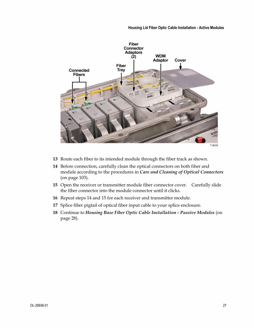
13 Route each fiber to its intended module through the fiber track as shown.
14 Before connection, carefully clean the optical connectors on both fiber and module according to the procedures in Care and Cleaning of Optical Connectors (on page 103).
15 Open the receiver or transmitter module fiber connector cover. Carefully slide the fiber connector into the module connector until it clicks.
16 Repeat steps 14 and 15 for each receiver and transmitter module.
17 Splice fiber pigtail of optical fiber input cable to your splice enclosure.
18 Continue to Housing Base Fiber Optic Cable Installation - Passive Modules (on page 28).

Chapter 2 Installation
28 OL-29936-01
Housing Base Fiber Optic Cable Installation - Passive Modules
Overview
The Model GS7000 Optical Hub housing comes with six fiber cable entry ports, two on the lid and four on the base. The lid ports utilize a standard 4 to 12 count FSC cable connecting the actives modules, such as EDFAs and optical switches, to the fiber closure. The base ports utilize a 24 to 48 count MPO (multi-fiber push-on) FSC for connection between the passive modules and the fiber distribution plant feeding nodes. Refer to Housing Lid Fiber Optic Cable Installation - Active Modules (on page 20) for instructions on housing lid FSC installation.
The Model GS7000 Optical Hub can accept a fiber optic cable connector for the passive modules in the housing base from either the left side (ports TP1 and TP2) or the right side (ports TP4 and TP5) of the housing, or both. The fiber optic cable(s) carries forward and reverse optical signals.
This procedure assumes a specific type of connector as an example. Your connector may be different from the one shown in these illustrations. Be sure to install the connector according to the connector manufacturer’s instructions.
Important: Fiber optic cable installation is a critical procedure. Incorrect installation can result in severely degraded performance. Be sure to carefully follow fiber connector manufacturer’s instructions. See Care and Cleaning of Optical Connectors (on page 103).
MPO FSC Color Code and Assignment
Fiber connectors and adapters are labeled with the following color code.
Note: This is only a suggested setup. Your fiber assignment may be different. Refer to your network diagrams to verify your color code.
#1 Bundle (Blue)
1 Blue
2 Orange
3 Green
4 Brown
Fiber # Fiber Color
5 Slate
6 White
7 Red
8 Black
9 Yellow
10 Violet
11 Pink (Rose)
12 Aqua
13 Blue
14 Orange
15 Green
16 Brown
Fiber # Fiber Color
17 Slate
18 White
19 Red
20 Black
21 Yellow
22 Violet
23 Pink (Rose)
24 Aqua
25 Blue
26 Orange
27 Green
28 Brown
Fiber # Fiber Color
29 Slate
30 White
31 Red
32 Black
33 Yellow
34 Violet
35 Pink (Rose)
36 Aqua
37 Blue
38 Orange
39 Green
40 Brown
Fiber # Fiber Color
41 Slate
42 White
43 Red
44 Black
45 Yellow
46 Violet
47 Pink (Rose)
48 Aqua
#2 Bundle (Orange) #4 Bundle (Brown)#3 Bundle (Green)
1
2
3
4
Node #
Forward
5
6
7
8
future
future
future
future
1
2
3
4
Node #
Return
5
6
7
8
future
future
future
future
9
10
11
12
Node #
Forward
13
14
15
16
future
future
future
future
9
10
11
12
Node #
Return
13
14
15
16
future
future
future
future
TP623

Housing Base Fiber Optic Cable Installation - Passive Modules
OL-29936-01 29
Fiber Management System
The fiber management system for passive modules is made up of two fiber slack spools and a fiber routing track. The fiber slack spools provide a convenient location to store excess fiber in the node. The fiber slack spools are located at each end of the housing base just inside the fiber entry ports for the passive devices. The fiber routing track provides a channel for routing fiber pigtails to their appropriate passive modules.
The following illustration shows the location of these components.
Procedure
Install fiber optic cable as described below.
WARNING:
Laser light hazard. The laser light source on this product emits invisible laser radiation. Avoid direct exposure. Never look into the end of an optical fiber or connector. Failure to observe this warning can result in eye damage or blindness.
Do not apply power to this product if the fiber is unmated or unterminated.
Do not stare into an unmated fiber or at any mirror-like surface that could reflect light that is emitted from an unterminated fiber.
Do not view an activated fiber with optical instruments.

Chapter 2 Installation
30 OL-29936-01
1 The first step depends on whether the fiber optic cable is factory installed or not.
IF... THEN...
fiber optic cable is factory installed
splice fiber pigtail of optical fiber input cable to your splice enclosure and continue to Fiber Optic Connections - Active to Passive Modules (on page 33).
fiber optic cable is not installed
go to step 2.
2 Select a left side (ports TP1 or TP2) or a right side (ports TP4 or TP5) fiber connection port for use and remove its sealing plug.
3 Slip a length of heat shrink tubing over the MPO fiber cable connectors and past the main body nut. Use a piece long enough to cover the cable connector and fiber port nut when assembled later.
4 One at a time, carefully insert the MPO fiber cable connectors through the fiber connection port and into the hub housing. Do not bend or kink fibers.

Housing Base Fiber Optic Cable Installation - Passive Modules
OL-29936-01 31
5 Hold the individual fiber cables to prevent them from rotating and carefully thread the 5/8-inch threaded nut into the threaded hole of the fiber port. Tighten to 20 to 25 ft-lbs (27.1 to 33.9 Nm).
6 Firmly tighten the main body nut against the 5/8-inch threaded nut, and then the back rotational nut against the main body nut.
7 Push the heat shrink tubing over the connector body and fiber port and shrink in place.
8 Identify the MPO fibers connectors according to their labels and determine to which passive device each one will connect.
9 Carefully wind the individual fiber cables around the fiber slack spool. Be sure to leave enough cable length so that each connector can reach its intended passive module.
10 Route each fiber to its intended module through the fiber track as shown.

Chapter 2 Installation
32 OL-29936-01
11 Before connection, carefully clean the optical connectors on both fiber and module according to the procedures in Care and Cleaning of Optical Connectors (on page 103).
12 Open the passive module fiber connector cover. Carefully slide the fiber connector into the module connector until it clicks.
13 Repeat steps 11 and 12 for each passive module.
14 Splice fiber pigtail of the MPO optical fiber cable to your splice enclosure.
15 Continue to Fiber Optic Connections - Active to Passive Modules (on page 33).

Fiber Optic Connections - Active to Passive Modules
OL-29936-01 33
Fiber Optic Connections - Active to Passive Modules
Overview
The Model GS7000 Optical Hub allows for the required fiber optic interconnections between the active and passive modules within the hub housing.
This procedure assumes a specific type of connector as an example. Your connector may be different from the one shown in these illustrations. Be sure to install the connector according to the connector manufacturer’s instructions.
Important: Fiber optic cable installation is a critical procedure. Incorrect installation can result in severely degraded performance. Be sure to carefully follow fiber connector manufacturer’s instructions. See Care and Cleaning of Optical Connectors (on page 103).
Fiber Management System
The fiber management system for interconnecting the active and passive modules consists of a fiber slack spool with integrated fiber track.
The fiber slack spool is mounted in position 11 in the housing lid. The integrated fiber track routes the fibers between the active modules in the housing lid and the passive modules in the housing base.
The following illustration shows the location of these components.

Chapter 2 Installation
34 OL-29936-01
Procedure
Install fibers as described below.
WARNING:
Laser light hazard. The laser light source on this product emits invisible laser radiation. Avoid direct exposure. Never look into the end of an optical fiber or connector. Failure to observe this warning can result in eye damage or blindness.
Do not apply power to this product if the fiber is unmated or unterminated.
Do not stare into an unmated fiber or at any mirror-like surface that could reflect light that is emitted from an unterminated fiber.
Do not view an activated fiber with optical instruments.

Fiber Optic Connections - Active to Passive Modules
OL-29936-01 35
1 The first step depends on whether the fibers are factory installed or not.
IF... THEN...
fibers are factory installed
Continue to RF Cable Installation (on page 37).
fibers are not installed
go to step 2.
2 Determine which active modules must be connected to which passive modules for your specific network architecture.
3 Remove the two screws from the fiber slack spool assembly and partially remove the fiber slack spool from the housing as shown in the following illustration.
4 Route one end of a fiber to its intended active module through the fiber routing track in the housing lid. Repeat this step for each active module.
5 Carefully wind the individual fiber cables around the fiber slack spool. Be sure to leave enough cable length so that each connector can reach its intended passive module.

Chapter 2 Installation
36 OL-29936-01
Note: It may take a few attempts to determine the correct length of fiber to reach each passive module. It's best to not insert the fibers in the routing tracks while estimating the proper length. Rather, position the fibers on top of the tracks while estimating.
6 Route each fiber to its intended passive module through the fiber track on the fiber slack spool and then through the passive device fiber routing track as necessary.
7 Before connection, carefully clean the optical connectors on both fiber and module according to the procedures in Care and Cleaning of Optical Connectors (on page 103).
8 Open the various module fiber connector covers. Carefully slide the fiber connectors into the module connectors until they click.
9 Continue to RF Cable Installation (on page 37).

RF Cable Installation
OL-29936-01 37
RF Cable Installation
Overview
The Model GS7000 Optical Hub can accept up to two RF cables. These cables carry forward path RF signal inputs and reverse path RF signal outputs to and from the Status Monitor module. The RF cables also supply the 45 to 90 VAC power input to the hub.
Trimming the Center Conductor
The Model GS7000 Optical Hub requires pin-type connectors for all RF connections.
Standard pin connectors, with pins extending 1.5 in. to 1.6 in. (3.8 cm to 4.064 cm) from connector shoulder, require no trimming. You must trim longer pins before inserting them into the housing.

Chapter 2 Installation
38 OL-29936-01
Trimming Using the Integrated Cradle
To trim long pins using the integrated cradle, follow these steps.
1 Place the connector on the cradle as shown in the following illustration.
2 If the center conductor extends past the CUT stanchion on the housing, trim the pin flush with the end of the CUT stanchion.
3 Remove any burrs or sharp edges from the trimmed end of the pin.
Trimming Using the Strip Line Mark
To trim long pins using the strip line mark on the housing, follow these steps.
1 Place the connector above the entry port so that it lines up with its installed position.

RF Cable Installation
OL-29936-01 39
2 If the center conductor extends past the STRIP line on the housing, trim the pin flush with the STRIP line.
3 Remove any burrs or sharp edges from the trimmed end of the pin.
Connecting the RF Cables to the Housing
Follow these steps to connect the RF cables.
1 Determine which ports, RF3 or RF6 or both, receive an RF cable for your configuration.
2 The length of the RF connector center pin is critical to proper operation. The pin length must be 1.6 inches (4.064 cm). Trim pin if necessary before installation. See Trimming the Center Conductor (on page 37).
Note: Assemble each RF connector to its cable according to manufacturer’s instructions.
3 Remove the sealing plug of each port to which cables connect. Note that ports RF3 and RF6 have the option of a vertical or horizontal connection.
4 Insert the appropriate coaxial connector of each RF cable to the desired housing port and torque to the manufacturer’s specification. Do not exceed recommended torque.
5 Repeat steps 2 through 4 for each RF port used.
6 Continue to Applying Power to the Hub.

Chapter 2 Installation
40 OL-29936-01
Applying Power to the Hub
Overview
The Model GS7000 Optical Hub requires input power of 45 to 90 VAC from and external power source. This power is supplied through the RF cables connected to port 3 and/or port 6 on the housing. The incoming AC power is feed to one or two power supply modules which in turn supply four well-regulated DC output voltages to the hub's internal modules, as shown in the following illustration. Refer to Power Supply Module (on page 80) for a complete description of the power supplies.
The powering configuration is flexible and can be changed to meet most network requirements. Power direction is configured by installing AC shunts for the ports through which you want to pass AC power. An AC segmentable shunt is provided to configure power direction between the two sides of the node.
Hub Powering Procedure
Follow these steps to apply power.
1 Determine which of the RF cables, connected to port 3 or port 6 or both, will carry the 45 to 90 VAC input power.
2 Install shunts in the locations that correspond to the AC-powered RF ports. Each port’s shunt is located on the RF amplifier module near the port as shown in the following illustration.

Applying Power to the Hub
OL-29936-01 41
Note: Shunts are available with both red and black tops. Use red to indicate that power is applied to that port. Use black to indicate that input power is not applied, but passed. Remove shunts to block AC power at the individual ports.
3 The next step depends on how many power supplies are installed and whether or not you want power to pass through the hub. Use the following table to determine the proper shunt installation.
IF... AND YOU WANT... Port 3 AC1 Shunt
AC Seg-mentable shunt
Port 6 AC2 Shunt
a single AC/DC power supply is installed in slot 2 as the Primary power supply and power is applied to Port 3 only
NO power pass-through
X
power pass-through
X X X
a single AC/DC power supply is installed in slot 2 as the Primary power supply and power is applied to Port 6 only
NO power pass-through
X X
power pass-through
X X X
dual AC/DC power supplies are installed and power is applied to Port 3 only
NO power pass-through
X X
power pass-through
X X X
dual AC/DC power supplies are installed and power is applied to Port 6 only
NO power pass-through
X X
power pass-through
X X X
dual AC/DC power supplies are installed and power is applied to Port 3 and to Port 6
NO power pass-through
X X
power pass-through
(Configuration Not Allowed)
Note: "X" indicates a shunt is installed in that location.

Chapter 2 Installation
42 OL-29936-01
Continue to Voltage Check Procedure.
Voltage Check Procedure
Always check both AC and DC voltages during initial setup of the Model GS7000 Optical Hub.
Follow these steps to check AC and DC voltages.
1 Use a true-rms DVM to check for 45 to 90 VAC input voltage at the AC test point on the power supply module.
2 Check for the various DC output voltages (+24.5, +8.5, -6.0, and +5.5) of the power supply at the DC test points on the power supply module.
3 Verify that the Power ON LED on the receiver module is on.
4 Carefully close the housing lid. See Opening and Closing the Housing (on page 94).

OL-29936-01 43
Introduction
This chapter describes how to set up and operate the Model GS7000 Optical Hub. These procedures assume the hub is installed according to the procedures in Chapter 2 of this manual.
Network Requirements
Refer to your network design diagrams during setup. The design diagrams should specify the exact input and output signal levels required for your network.
3 Chapter 3 Setup and Operation
In This Chapter
Tools and Test Equipment ................................................................... 44
AC Entry Module .................................................................................. 45
Optical Passive Modules ...................................................................... 46
Optical Amplifier (EDFA) Modules ................................................... 53
Optical Amplifier Power In and Power Out Test Point Use and Operation ....................................................................................... 70
Optical Switch Module ........................................................................ 72
Status Monitor/Local Control Module .............................................. 77
Power Supply Module ......................................................................... 80
Hub Architecture Examples ................................................................ 84

Chapter 3 Setup and Operation
44 OL-29936-01
Tools and Test Equipment
Required Tools and Test Equipment
Tools and test equipment required for setup are listed below. Equivalent items may be substituted. Ensure test equipment is calibrated and in good working order.
Fluke Model 77 (or equivalent) true-rms digital voltmeter (DVM) with 0.001 resolution.
Signal generator capable of generating carriers at 55.25 MHz and 745.25 MHz
“F” barrel adapter - 1 GHz
Field strength meter capable of measuring up to 1002 MHz
Field sweep receiver/transmitter with a minimum bandwidth of 900 MHz
EXFO FOT 22AX optical power meter with adapters
Fiber optic jumper to test transmitter optical output power
Glendale Technologies optical eye protection blocking 900–1600 nm light

AC Entry Module
OL-29936-01 45
AC Entry Module
AC Powering
The AC entry module is the hub's power entry and power passing module. AC power enters the module via ports 3 or 6 on the housing. The module is capable of passing power or providing redundant powering depending on which shunts are installed. It powers both DC power supplies and passes information regarding power to the status monitor in the housing lid via a molded RF cable assembly.
RF Section
The AC entry module contains two RF connectors that connect to the OIB via a standard GS7000 molded RF cable assembly. The AC power and RF signal are received from ports 3 and/or 6. The AC power is then coupled off via the AC bypass circuitry and routed to the AC1/DC and AC2 connectors. The forward Status Monitor RF signals combine at an RF switch, where either the port 3 or port 6 signal is selected, subjected to a diplex filter, and then passed to the OIB via one of cables in the standard GS7000 molded RF cable pair.
In the reverse path, the Status Monitor RF signal is generated by the Status Monitor module located in slot 7 of the OIB and routed to the AC entry module via one of the cables in the GS7000 molded RF cable pair. The signal is then subjected to a diplex filter and directed by the RF switch to either port 3 or port 6 before being transmitted to the RF plant.
Note: The Status Monitor's transponder core communicates through the AC Entry module. The optical hub must be on an RF plant in order to monitor the optical amplifier modules and optical switch modules remotely.

Chapter 3 Setup and Operation
46 OL-29936-01
Optical Passive Modules
NCBC Combiners without Multiplexers/Demultiplexers
These modules are only used in the forward path. The narrowcast signal is provided in an 8-fiber ribbon cable using an MPO connector. Broadcast signals are split with either a 1x8 splitter or with two 1x4 splitters. Narrowcast and broadcast signals are combined using integrated BWDMs and connect to the distribution cable using an 8-fiber MPO connector.
The following illustration shows an example of the module.

Optical Passive Modules
OL-29936-01 47
NCBC Combiners with Integrated Forward Demux and Return Mux
This module handles both the forward and reverse path. In the forward path, it splits narrowcast signals with a 1x8 demultiplexer and broadcast input signals with a 1x8 splitter. Narrowcast and broadcast signals are combined using integrated BWDMs and connect to the distribution cable using an 8-fiber MPO connector. The reverse signal is received from the distribution cable via an 8-fiber MPO connector. The signal goes through a 1x8 multiplexer and is sent in the reverse path on one fiber.
The following illustration shows an example of the module.

Chapter 3 Setup and Operation
48 OL-29936-01
NCBC Combiners with Forward Demux
These modules are only used in the forward path. The narrowcast signal is split with a 1x8 demultiplexer. Broadcast signals are split with either a 1x8 splitter or two 1x4 splitters. Narrowcast and broadcast signals are combined using integrated BWDMs and connect to the distribution cable using an 8-fiber MPO connector.
The following illustration shows an example of the module.

Optical Passive Modules
OL-29936-01 49
DWDM and CWDM 1x8
This module can be used in the forward and reverse paths. When used in the forward path, the module functions as an optical demultiplexer. Multiple optical wavelengths coming in over a single fiber are injected into the common port of the module, the wavelengths are separated into its frequency wavelengths. In the revere path the module functions as a multiplexer. Multiple input fibers carrying optical signals at different wavelengths are received through the 8-fiber MPO "IN OUT" connector and multiplexed into one output fiber.
The following illustration shows an example of the module.
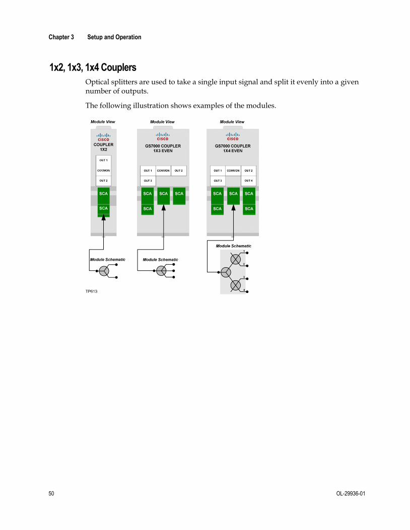
Chapter 3 Setup and Operation
50 OL-29936-01
1x2, 1x3, 1x4 Couplers
Optical splitters are used to take a single input signal and split it evenly into a given number of outputs.
The following illustration shows examples of the modules.

Optical Passive Modules
OL-29936-01 51
1x8 Dual 1x4 Coupler
The 1x8 dual 1x4 coupler allows for input through a single fiber using the 1x8 port or two fibers using the 1x4 ports. The signals are split using a single 1x8 splitter or two 1x4 splitters. The output to the distribution cable is via the 8-fiber MPO connector.
The following illustration shows an example of the module.

Chapter 3 Setup and Operation
52 OL-29936-01
BWDM 1x2 Red/Blue and 1x4 Filters
These filters can be used in both the forward and reverse paths. The signals are split using a 1x2 and 1x4 multiplexer/demultiplexer respectively.
The following illustrations show examples of the modules.

Optical Amplifier (EDFA) Modules
OL-29936-01 53
Optical Amplifier (EDFA) Modules
Optical Amplifier Module Descriptions
Erbium-doped fiber amplifier modules are available in two categories: broadcast and narrowcast. Broadcast EDFAs are used for the amplification of broadcast signals which are carried by a single optical channel anywhere between 1530 nm and 1565 nm. Narrowcast EDFAs are used for the amplification of multiple optical channels carrying narrowcast signals. For uniformity of performance, narrowcast EDFAs need to be gain flattened in the designated operating wavelength range between 1528 nm and 1562 nm.
Broadcast EDFAs are available in 17 dBm, 20 dBm, and 22 dBm versions. Narrowcast EDFAs are available in 17 dBm or 21 dBm versions to fit any architecture for requirements like DWDM narrowcasting. Both broadcast and narrowcast EDFAs can be operated in constant power and constant gain modes. The default setting for a broadcast EDFA is constant power mode, while the default setting for a narrowcast EDFA is constant gain mode.
EDFA modules are single-wide, single-output, devices. Each module is connected to one input fiber and one output fiber through optical fiber connectors on the side of the module housing. The modules can be mounted in slots 3 through 6 and 8 through 11 on the optical interface board in the housing lid. The modules use a color-coded reversible pin adaptor. One side is blue and the other side is red. The pin alignment is slightly different on the two sides.

Chapter 3 Setup and Operation
54 OL-29936-01
Important: For mounting in a hub, the pin adaptor must be installed with the blue side facing out as shown.
Refer to Optical Amplifier and Optical Switch Module Pin Adaptor (on page 100) for pin adaptor installation instructions.
Optical Amplifier Module Models
The following table describes the available EDFA models for the Model GS7000 Optical Hub.
Model Description Operating Mode
GS-EDFA-BCST-17-SA
17 dBm broadcast EDFA
Default: Constant power at 17 dBm
Optional: Constant gain at 12 dB ± 2 dB
GS-EDFA-BCST-20-SA
20 dBm broadcast EDFA
Default: Constant power at 20 dBm
Optional: Constant gain at 15 dB ± 2 dB
GS-EDFA-BCST-22-SA
22 dBm broadcast EDFA
Default: Constant power at 22 dBm
Optional: Constant gain at 17 dB ± 2 dB
GS-EDFA-GF- 17L
17 dBm gain flattened low gain EDFA
Default: Constant gain at 7 dB (± 2 dB range)
Optional: Constant power at 17 dBm
GS-EDFA-GF- 17H
17 dBm gain flattened high gain EDFA
Default: Constant gain at 12 dB (± 2 dB range)
Optional: Constant power at 17 dBm
GS-EDFA-GF- 21L
21 dBm gain flattened low gain EDFA
Default: Constant gain at 11 dB (± 2 dB range)
Optional: Constant power at 21 dBm
GS-EDFA-GF- 21H
21 dBm gain flattened high gain EDFA
Default: Constant gain at 16 dB (± 2 dB range)
Optional: Constant power at 21 dBm

Optical Amplifier (EDFA) Modules
OL-29936-01 55
Optical Amplifier Module Diagram
The following block diagram shows how the optical amplifier module functions.
Optical Amplifier Operating Parameters
This section is a reference for the operating parameters of the EDFA. The EDFA is configured through the Status Monitor/Local Control Module in the housing lid. Refer to the Model GS7000 Hub/Node Status Monitor/Local Control Module Installation and Configuration Guide, part number OL-29937-01, for complete instructions on configuring the EDFA.

Chapter 3 Setup and Operation
56 OL-29936-01
Configurable Parameters
The following table defines the configurable parameters for the EDFA.
Param Name
Products Function DefaultValue
Min Typical Max Step Unit
Mode All Sets operating mode of amplifier
[A] na na na Constant Gain (0) Constant Power (1)
na
Enable All Enables or disables amplifier
Off(0) na na na Off(0) On(1)
na
Set Power
BCST 17 Sets optical output level [B]
17 14 17 17 0.1 dBm
BCST 20 Sets optical output level [B]
20 17 20 20 0.1 dBm
BCST 22 Sets optical output level [B]
22 19 22 22 0.1 dBm
GF 17 Sets optical output level [B]
17 14 17 17 0.1 dBm
GF 21 Sets optical output level [B]
21 18 21 21 0.1 dBm
Set Gain BCST 17 Sets gain level in Constant Gain Mode [A][B]
12 10 12 14 0.1 dB
BCST 20 Sets gain level in Constant Gain Mode [A][B]
15 13 15 17 0.1 dB
BCST 22 Sets gain level in Constant Gain Mode [A][B]
17 15 17 19 0.1 dB
GF 17H [A] 12 10 12 14 0.1 dB
GF 21H [A] 16 14 16 18 0.1 dB
GF 17L [A] 7 5 7 9 0.1 dB
GF 21L [A] 11 9 11 13 0.1 dB
[A] For the Broadcast amplifier, the default is Constant Power. For the Narrowcast amplifier, the default is Constant Gain.
[B] In Constant Power mode only.

Optical Amplifier (EDFA) Modules
OL-29936-01 57
Operating Status Parameters
The following table defines the monitored operating parameters for the EDFA.
Parameter Name Function Typical Value Units
Optical Input Power Optical input power 5.0 dBm
Output Power Optical output power 19.5 dBm
Laser Temperature Laser temperature 25.0 or 45 degC
Laser Bias Current Limit Laser operating current limit 0.825 A
Laser Bias Current Laser operating current 0.625 A
TEC Current Thermoelectric cooler current 0.25 A
Module Temperature Module temperature 26.5 degC
Laser On Time Time the laser has been on 1.0 Hrs
Alarm Parameters
The following table defines the alarm parameters for the EDFA.
Alarm Name Major High
Minor High
Minor Low
Major Low
Values Typical Value
Hysteresis Units
Laser Bias Current
-0.001 -0.010 na na Ok
Alarm
0.625 0.001 A
Optical Output Level
1.0 0.7 -0.7 -1.0 Ok
Alarm
17
20
22
0.1 dBm
Input Power [1]
[5] [5] [5] [5] Ok
Alarm
na 0.1 dBm
Laser Temperature [1][4]
20.0 15.0 -15.0 -20.0 Ok
Alarm
25.0 1.0 degC
OIB Voltage Status [1][2]
na na na na Ok
Alarm
Ok na na
Internal Power Status [1][3]
na na na na Ok
Alarm
na na na
Laser Enabled Status [1]
na na na na Ok
Alarm
na na na

Chapter 3 Setup and Operation
58 OL-29936-01
[1] This alarm sets the unit to the safe state. In the safe state the amplifier is turned off causing the optical amplifier output to be disabled.
[2] This alarm tests for presence of +24V, -6V from the OIB.
[3] This alarm indicates the state of the internal voltages (+24V, +5.0V, Vref).
[4] See following for laser nominal set point temperature based on module temperature.
[5] See next table for input power alarm values.
Input Power Alarm Parameters
The following tables define the input power alarm parameters for the EDFA.
Gain Flattened EDFA - Constant Gain Mode (Default)
Product Type Major High
Minor High
Minor Low
Major Low
Values Typical Value
Hysteresis Units
17.0 / 21.0 dBm Low Gain
45.0 25.0 -8.0 -10.0 Ok
Alarm
-7.0 0.1 dBm
17.0 / 21.0 dBm High Gain
45.0 25.0 -13.0 -15.0 Ok
Alarm
-12.0 0.1 dBm
Gain Flattened EDFA - Constant Power Mode
Product Type Major High
Minor High
Minor Low
Major Low
Values Typical Value
Hysteresis Units
17.0 / 21.0 dBm
Low/High Gain
45.0 25.0 0 -10.0 Ok
Alarm
5.0 0.1 dBm
Broadcast EDFA - Constant Power Mode (Default)
Product Type Major High
Minor High
Minor Low
Major Low
Values Typical Value
Hysteresis Units
17.0/20.0/22.0 dBm
45.0 25.0 0 -10.0 Ok
Alarm
5.0 0.1 dBm
Broadcast EDFA - Constant Gain Mode
Product Type Major High
Minor High
Minor Low
Major Low
Values Typical Value
Hysteresis Units
17.0/20.0/22.0 dBm
45.0 25.0 -13.0 -15.0 Ok
Alarm
-12.0 0.1 dBm

Optical Amplifier (EDFA) Modules
OL-29936-01 59
Laser Temperature Set Point Adjustment
In an effort to reduce EDFA power consumption, the laser temperature set point is changed based on EDFA module temperature and type of laser used. The laser set temperature is between 25°C and 45°C. The actual laser temperature can be in the ±5°C range around the set point.
Broadcast EDFA Power and Gain Setup
Broadcast EDFAs are optimized for single optical channel application to achieve best performance for analog video signals. For single channel operation the operating wavelength range is from 1530 nm to 1565 nm. Constant power operation mode is usually desired for the application. Constant gain mode is available as an option.
Power and Gain Terminology
The following table explains common terminology used in this section.
Term Abbreviation Definition
Constant Power Mode
In constant power mode the total output power from the amplifier is set via the LCM. Once set, any change that occurs to the input signal within the specification window results in no change to the output power.
Note: In this mode, the composite gain, the gain per wavelength, and the output power per wavelength may not stay constant.
Constant Gain Mode
In constant gain mode the gain of the optical amplifier is set via the LCM. Once the gain is set, the amplifier automatically adjusts to any change to the composite input power or to an individual wavelength being dropped or added. This adjustment results in a corresponding change to the composite output power.
Note: In this mode, constant composite output power is not maintained, but constant gain per wavelength, constant composite gain, and constant output power per wavelength are maintained.
Input power per wavelength
PIN/λ Amount of power present at a particular wavelength at the input to the amplifier.
Composite input power
PIN/C Sum of the power present in all the individual wavelengths at the input to the amplifier.
Output power per wavelength
POUT/λ Amount of power present at a particular wavelength at the output to the amplifier.

Chapter 3 Setup and Operation
60 OL-29936-01
Term Abbreviation Definition
Composite output power
POUT/C Sum of the power present in all the individual wavelengths at the output of the amplifier.
Composite gain Gc Amount of gain the composite input of the power to the amplifier will receive.
Constant Power Mode (Default)
Constant power mode is the default operating mode for broadcast EDFAs.
The EDFAs also have an attenuation feature with a 3 dB attenuation range. For example, for the 17 dBm amplifier, an attenuation of 0.0 dB to 3.0 dB in 0.1 dB steps can be set to achieve the output powers of 17.0 dBm to 14.0 dBm in 0.1dBm steps, respectively. See the following table.
Model Composite Output Power (POUT/C)
GS-EDFA-BCST-17-SA Default: 17 dBm
Optional: 14.0 dBm to 16.9 dBm in 0.1 dB steps
GS-EDFA-BCST-20-SA Default: 20 dBm
Optional: 17.0 dBm to 19.9 dBm in 0.1 dB steps
GS-EDFA-BCST-22-SA Default: 22 dBm
Optional: 19.0 dBm to 21.9 dBm in 0.1 dB steps
Constant Gain Mode (Optional)
Broadcast EDFAs can optionally be operated in constant gain mode. The mode is set through the LCM. The following table shows the operating conditions in constant gain mode and an example of input and output ranges for a 16 channel system.
Model Set Gain (Gc) Composite Input (PIN/C)
(1λ 16 λ)
Composite Output (POUT/C)
(1λ 16 λ)
GS-EDFA-BCST-17-SA
10 dB
11 dB
12 dB
13 dB
14 dB
-5 dBm 7 dBm
-6 dBm 6 dBm
-7 dBm 5 dBm
-8 dBm 4 dBm
-9 dBm 3 dBm
5 dBm 17 dBm
5 dBm 17 dBm
5 dBm 17 dBm
5 dBm 17 dBm
5 dBm 17 dBm

Optical Amplifier (EDFA) Modules
OL-29936-01 61
GS-EDFA-BCST-20-SA
13 dB
14 dB
15 dB
16 dB
17 dB
-5 dBm 7 dBm
-6 dBm 6 dBm
-7 dBm 5 dBm
-8 dBm 4 dBm
-9 dBm 3 dBm
8 dBm 20 dBm
8 dBm 20 dBm
8 dBm 20 dBm
8 dBm 20 dBm
8 dBm 20 dBm
GS-EDFA-BCST-22-SA
15 dB
16 dB
17 dB
18 dB
19 dB
-5 dBm 7 dBm
-6 dBm 6 dBm
-7 dBm 5 dBm
-8 dBm 4 dBm
-9 dBm 3 dBm
10 dBm 22 dBm
10 dBm 22 dBm
10 dBm 22 dBm
10 dBm 22 dBm
10 dBm 22 dBm
At a set gain condition, the EDFA maintains the gain as long as the output power is below the power limit. For example, for GS-EDFA-BCST-17-SA EDFA, if the set gain is 12 dB, when input power is in the range from -7 dBm to 5 dBm, the output power will be in the range from 5 dBm to 17 dBm. However, if the input is larger than 5 dBm, the output power cannot go beyond 17 dBm to maintain the 12 dB gain. Instead, it will be operated at 17 dBm output. If the input goes below the specified range, the EDFA still tries to maintain the set gain. However, if the composite input power goes too low, the monitoring accuracy will degrade, which could result in poor output power stability.
Narrowcast EDFA Power and Gain Setup
Narrowcast EDFAs are optimized for multiple optical channel application to achieve uniform performance over the operation band digital video or data signals. The designed bandwidth is about 34 nm from 1528 nm to 1562 nm, which can accommodate 40+ optical channels (ITU20 - ITU62) at 100 GHz spacing. Constant gain operation mode is usually desired for the application because of the possibility that optical channels can be added or dropped. Constant power mode is available as an option.
Constant Gain Mode (Default)
Four models of narrowcast EDFAs are available to suit applications that require different output power and gain. Each of the narrowcast EDFA models has a default gain setting. The narrowcast EDFAs can be operated at other gain values within the range Default gain ± 2 dB. However, EDFAs operated at the default gain condition can achieve the most uniform performance for the all optical channels across the band.

Chapter 3 Setup and Operation
62 OL-29936-01
The following information is required to select a gain flattened EDFA for a multi-channel system:
Maximum number of optical channels for the designed system: N =
Input power per channel: PIN/λ =
Required output power per channel: POUT/λ =
Required gain: G = POUT/λ / PIN/λ =
With the above information, use the following table to select an appropriate EDFA.
Maximum channel number
Required output per channel
Required gain EDFA model
40 1 dBm 5 dB - 9 dB GS-EDFA-GF-17L-SA
10 dB - 14 dB GS-EDFA-GF-17H-SA
5 dBm 9 dB - 13 dB GS-EDFA-GF-21L-SA
14 dB - 18 dB GS-EDFA-GF-21H-SA
32 2 dBm 5 dB - 9 dB GS-EDFA-GF-17L-SA
10 dB - 14 dB GS-EDFA-GF-17H-SA
6 dBm 9 dB - 13 dB GS-EDFA-GF-21L-SA
14 dB - 18 dB GS-EDFA-GF-21H-SA
24 3.2 dBm 5 dB - 9 dB GS-EDFA-GF-17L-SA
10 dB - 14 dB GS-EDFA-GF-17H-SA
7.2 dBm 9 dB - 13 dB GS-EDFA-GF-21L-SA
14 dB - 18 dB GS-EDFA-GF-21H-SA
16 5 dBm 5 dB - 9 dB GS-EDFA-GF-17L-SA
10 dB - 14 dB GS-EDFA-GF-17H-SA
9 dBm 9 dB - 13 dB GS-EDFA-GF-21L-SA
14 dB - 18 dB GS-EDFA-GF-21H-SA
8 8 dBm 5 dB - 9 dB GS-EDFA-GF-17L-SA
10 dB - 14 dB GS-EDFA-GF-17H-SA
12 dBm 9 dB - 13 dB GS-EDFA-GF-21L-SA
14 dB - 18 dB GS-EDFA-GF-21H-SA

Optical Amplifier (EDFA) Modules
OL-29936-01 63
At a set gain condition, the EDFA maintains the gain as long as the output power is below the power limit. For example, for GS-EDFA-NCST-17L-SA EDFA, if the set gain is 7 dB, when input power is in the range from -5 dBm to 10 dBm, the output power will be in the range from 2 dBm to 17 dBm. However, if the input is larger than 10 dBm, the output power cannot go beyond 17 dBm to maintain the 7 dB gain; instead, it will be operated at 17 dBm output. If the input goes below the specified range, the EDFA still tries to maintain the set gain. However, if the composite input power goes too low, the monitoring accuracy will degrade, which could result in poor output power stability.
The following tables list the input and output power ranges in a few of the most common systems: an 8 wavelength system, a 16 wavelength system, a 24 wavelength system, a 32 wavelength system, and a 40 wavelength system. Systems with other wavelength counts can also be calculated.

Chapter 3 Setup and Operation
64 OL-29936-01
8 Wavelength System
An 8 wavelength system is designed to have a maximum capacity of 8 optical channels. The actual number of optical channels at the deployment can be 8 or less.
Model Set Gain (Gc) Composite Input (PIN/C)
(1λ 8 λ)
Composite Output (POUT/C)
(1λ 8 λ)
GS-EDFA-GF- 17L-SA
5 dB
6 dB
7 dB*
8 dB
9 dB
3 dBm 12 dBm
2 dBm 11 dBm
1 dBm 10 dBm
0 dBm 9 dBm
-1 dBm 8 dBm
8 dBm 17 dBm
8 dBm 17 dBm
8 dBm 17 dBm
8 dBm 17 dBm
8 dBm 17 dBm
GS-EDFA-GF- 17H-SA
10 dB
11 dB
12 dB*
13 dB
14 dB
-2 dBm 7 dBm
-3 dBm 6 dBm
-4 dBm 5 dBm
-5 dBm 4 dBm
-6 dBm 3 dBm
8 dBm 17 dBm
8 dBm 17 dBm
8 dBm 17 dBm
8 dBm 17 dBm
8 dBm 17 dBm
GS-EDFA-GF- 21L-SA
9 dB
10 dB
11 dB*
12 dB
13 dB
3 dBm 12 dBm
2 dBm 11 dBm
1 dBm 10 dBm
0 dBm 9 dBm
-1 dBm 8 dBm
12 dBm 21 dBm
12 dBm 21 dBm
12 dBm 21 dBm
12 dBm 21 dBm
12 dBm 21 dBm
GS-EDFA-GF- 21H-SA
14 dB
15 dB
16 dB*
17 dB
18 dB
-2 dBm 7 dBm
-3 dBm 6 dBm
-4 dBm 5 dBm
-5 dBm 4 dBm
-6 dBm 3 dBm
12 dBm 21 dBm
12 dBm 21 dBm
12 dBm 21 dBm
12 dBm 21 dBm
12 dBm 21 dBm
* Default gain setting

Optical Amplifier (EDFA) Modules
OL-29936-01 65
16 Wavelength System
A 16 wavelength system is designed to have a maximum capacity of 16 optical channels. The actual number of optical channels at the deployment can be 16 or less.
Model Set Gain (Gc) Composite Input (PIN/C)
(1λ 16 λ)
Composite Output (POUT/C)
(1λ 16 λ)
GS-EDFA-GF- 17L-SA
5 dB
6 dB
7 dB*
8 dB
9 dB
0 dBm 12 dBm
-1 dBm 11 dBm
-2 dBm 10 dBm
-3 dBm 9 dBm
-4 dBm 8 dBm
5 dBm 17 dBm
5 dBm 17 dBm
5 dBm 17 dBm
5 dBm 17 dBm
5 dBm 17 dBm
GS-EDFA-GF- 17H-SA
10 dB
11 dB
12 dB*
13 dB
14 dB
-5 dBm 7 dBm
-6 dBm 6 dBm
-7 dBm 5 dBm
-8 dBm 4 dBm
-9 dBm 3 dBm
5 dBm 17 dBm
5 dBm 17 dBm
5 dBm 17 dBm
5 dBm 17 dBm
5 dBm 17 dBm
GS-EDFA-GF- 21L-SA
9 dB
10 dB
11 dB*
12 dB
13 dB
0 dBm 12 dBm
-1 dBm 11 dBm
-2 dBm 10 dBm
-3 dBm 9 dBm
-4 dBm 8 dBm
9 dBm 21 dBm
9 dBm 21 dBm
9 dBm 21 dBm
9 dBm 21 dBm
9 dBm 21 dBm
GS-EDFA-GF- 21H-SA
14 dB
15 dB
16 dB*
17 dB
18 dB
-5 dBm 7 dBm
-6 dBm 6 dBm
-7 dBm 5 dBm
-8 dBm 4 dBm
-9 dBm 3 dBm
9 dBm 21 dBm
9 dBm 21 dBm
9 dBm 21 dBm
9 dBm 21 dBm
9 dBm 21 dBm
* Default gain setting

Chapter 3 Setup and Operation
66 OL-29936-01
24 Wavelength System
A 24 wavelength system is designed to have a maximum capacity of 24 optical channels. The actual number of optical channels at the deployment can be 24 or less.
Model Set Gain (Gc) Composite Input (PIN/C)
(1λ 24 λ)
Composite Output (POUT/C)
(1λ 24 λ)
GS-EDFA-GF- 17L-SA
5 dB
6 dB
7 dB*
8 dB
9 dB
-1.8 dBm 12 dBm
-2.8 dBm 11 dBm
-3.8 dBm 10 dBm
-4.8 dBm 9 dBm
-5.8 dBm 8 dBm
3.2 dBm 17 dBm
3.2 dBm 17 dBm
3.2 dBm 17 dBm
3.2 dBm 17 dBm
3.2 dBm 17 dBm
GS-EDFA-GF- 17H-SA
10 dB
11 dB
12 dB*
13 dB
14 dB
-6.8 dBm 7 dBm
-7.8 dBm 6 dBm
-8.8 dBm 5 dBm
-9.8 dBm 4 dBm
-10.8 dBm 3 dBm
3.2 dBm 17 dBm
3.2 dBm 17 dBm
3.2 dBm 17 dBm
3.2 dBm 17 dBm
3.2 dBm 17 dBm
GS-EDFA-GF- 21L-SA
9 dB
10 dB
11 dB*
12 dB
13 dB
-1.8 dBm 12 dBm
-2.8 dBm 11 dBm
-3.8 dBm 10 dBm
-4.8 dBm 9 dBm
-5.8 dBm 8 dBm
7.2 dBm 21 dBm
7.2 dBm 21 dBm
7.2 dBm 21 dBm
7.2 dBm 21 dBm
7.2 dBm 21 dBm
GS-EDFA-GF- 21H-SA
14 dB
15 dB
16 dB*
17 dB
18 dB
-6.8 dBm 7 dBm
-7.8 dBm 6 dBm
-8.8 dBm 5 dBm
-9.8 dBm 4 dBm
-10.8 dBm 3 dBm
7.2 dBm 21 dBm
7.2 dBm 21 dBm
7.2 dBm 21 dBm
7.2 dBm 21 dBm
7.2 dBm 21 dBm
* Default gain setting

Optical Amplifier (EDFA) Modules
OL-29936-01 67
32 Wavelength System
A 32 wavelength system is designed to have a maximum capacity of 32 optical channels. The actual number of optical channels at the deployment can be 32 or less.
Model Set Gain (Gc) Composite Input (PIN/C)
(1λ 32 λ)
Composite Output (POUT/C)
(1λ 32 λ)
GS-EDFA-GF- 17L-SA
5 dB
6 dB
7 dB*
8 dB
9 dB
-3 dBm 12 dBm
-4 dBm 11 dBm
-5 dBm 10 dBm
-6 dBm 9 dBm
-7 dBm 8 dBm
2 dBm 17 dBm
2 dBm 17 dBm
2 dBm 17 dBm
2 dBm 17 dBm
2 dBm 17 dBm
GS-EDFA-GF- 17H-SA
10 dB
11 dB
12 dB*
13 dB
14 dB
-8 dBm 7 dBm
-9 dBm 6 dBm
-10 dBm 5 dBm
-11 dBm 4 dBm
-12 dBm 3 dBm
2 dBm 17 dBm
2 dBm 17 dBm
2 dBm 17 dBm
2 dBm 17 dBm
2 dBm 17 dBm
GS-EDFA-GF- 21L-SA
9 dB
10 dB
11 dB*
12 dB
13 dB
-3 dBm 12 dBm
-4 dBm 11 dBm
-5 dBm 10 dBm
-6 dBm 9 dBm
-7 dBm 8 dBm
6 dBm 21 dBm
6 dBm 21 dBm
6 dBm 21 dBm
6 dBm 21 dBm
6 dBm 21 dBm
GS-EDFA-GF- 21H-SA
14 dB
15 dB
16 dB*
17 dB
18 dB
-8 dBm 7 dBm
-9 dBm 6 dBm
-10 dBm 5 dBm
-11 dBm 4 dBm
-12 dBm 3 dBm
6 dBm 21 dBm
6 dBm 21 dBm
6 dBm 21 dBm
6 dBm 21 dBm
6 dBm 21 dBm
* Default gain setting

Chapter 3 Setup and Operation
68 OL-29936-01
40 Wavelength System
A 40 wavelength system is designed to have a maximum capacity of 40 optical channels. The actual number of optical channels at the deployment can be 40 or less.
Model Set Gain (Gc) Composite Input (PIN/C)
(1λ 40 λ)
Composite Output (POUT/C)
(1λ 40 λ)
GS-EDFA-GF- 17L-SA
5 dB
6 dB
7 dB*
8 dB
9 dB
-4 dBm 12 dBm
-5 dBm 11 dBm
-6 dBm 10 dBm
-7 dBm 9 dBm
-8 dBm 8 dBm
1 dBm 17 dBm
1 dBm 17 dBm
1 dBm 17 dBm
1 dBm 17 dBm
1 dBm 17 dBm
GS-EDFA-GF- 17H-SA
10 dB
11 dB
12 dB*
13 dB
14 dB
-9 dBm 7 dBm
-10 dBm 6 dBm
-11 dBm 5 dBm
-12 dBm 4 dBm
-13 dBm 3 dBm
1 dBm 17 dBm
1 dBm 17 dBm
1 dBm 17 dBm
1 dBm 17 dBm
1 dBm 17 dBm
GS-EDFA-GF- 21L-SA
9 dB
10 dB
11 dB*
12 dB
13 dB
-4 dBm 12 dBm
-5 dBm 11 dBm
-6 dBm 10 dBm
-7 dBm 9 dBm
-8 dBm 8 dBm
4 dBm 21 dBm
4 dBm 21 dBm
4 dBm 21 dBm
4 dBm 21 dBm
4 dBm 21 dBm
GS-EDFA-GF- 21H-SA
14 dB
15 dB
16 dB*
17 dB
18 dB
-9 dBm 7 dBm
-10 dBm 6 dBm
-11 dBm 5 dBm
-12 dBm 4 dBm
-13 dBm 3 dBm
4 dBm 21 dBm
4 dBm 21 dBm
4 dBm 21 dBm
4 dBm 21 dBm
4 dBm 21 dBm
* Default gain setting

Optical Amplifier (EDFA) Modules
OL-29936-01 69
Constant Power Mode (Optional)
Narrowcast EDFAs can optionally be operated in constant power mode.
By default, the output power is the nominal output power for the narrowcast EDFA, which is equal to the composite output power at fully loaded condition in the constant gain mode.
Model Composite Output Power (POUT/C) Note
GS-EDFA-GF-17L-SA Default: 17 dBm
Optional: 16 dBm, 15 dBm, 14 dBm
PIN/C >5 dBm
GS-EDFA-GF-17H-SA Default: 17 dBm
Optional: 16 dBm, 15 dBm, 14 dBm
PIN/C >0 dBm
GS-EDFA-GF-21L-SA Default: 21 dBm
Optional: 20 dBm, 19 dBm, 18 dBm
PIN/C >5 dBm
GS-EDFA-GF-21H-SA Default: 21 dBm
Optional: 20 dBm, 19 dBm, 18 dBm
PIN/C >0 dBm
Note: The attenuator feature is available for the narrowcast EDFAs when they are set to constant power mode. The attenuation range is 3 dB.

Chapter 3 Setup and Operation
70 OL-29936-01
Optical Amplifier Power In and Power Out Test Point Use and Operation
The EDFA modules have test points that can be used to monitor input and output power levels when the units are in service.
The Power In test point provides a voltage proportional to the optical input power to the EDFA module. The Power Out test point provides a voltage proportional to the optical output power from the EDFA.
These voltages can be measured using a DC voltmeter (or DCV function on a multimeter) and applied to simple formulas to confirm nominal input and output power.
Power In Measurement 1 Place the positive (+) lead of a DC voltmeter on the Power In test point.
2 Place the negative (-) lead of the DC voltmeter on ground.
Note: When installed, the metal case of the EDFA module is at ground.
3 Record the voltage measurement and apply this formula:
Pin (dBm) = 8 * (Vin (volts) - 2.5)
For example, if Vin measures 3.1 V, the input power to the EDFA is approximately 8 * (3.1 - 2.5) = 8 * 0.6 = 4.8 dBm.
Note: Results are accurate to ± 0.5 dB at room temperature.

Optical Amplifier Power In and Power Out Test Point Use and Operation
OL-29936-01 71
Power Out Measurement 1 Place the positive (+) lead of a DC voltmeter on the Power Out test point.
2 Place the negative (-) lead of the DC voltmeter on ground.
Note: When installed, the metal case of the EDFA module is at ground.
3 Record the voltage measurement and apply this formula:
Pout (dBm) = 6.67 * (Vout (volts) - 0.7)
For example, if Vout measures 3.7 V, the output power from the EDFA is approximately 6.67 * (3.7 - 0.7) = 6.67 * 3 = 20 dBm.
Note: Results are accurate to ± 0.5 dB at room temperature.

Chapter 3 Setup and Operation
72 OL-29936-01
Optical Switch Module
Optical Switch Module Description
The optical switch module is used for switching the input of an EDFA module from a primary signal to a backup or secondary signal. The switch operates in the 1550 nm wavelength range since its application is high power/long haul systems that employ EDFAs.
The switch has two operating modes: manual and automatic. In automatic mode, the switch can be triggered by a loss of light. The loss of light activation triggers the switch when the light level drops below the threshold value set by the operator. In manual mode, the switch can be triggered through the Local Control Module (LCM).
The modules can be mounted in slots 3 through 6 and 8 through 10 on the optical interface board in the housing lid. The modules use a color-coded reversible pin adaptor. One side is blue and the other side is red. The pin alignment is slightly different on the two sides.

Optical Switch Module
OL-29936-01 73
Important: For mounting in a hub the pin adaptor must be installed with the blue side facing out as shown.
Refer to Optical Amplifier and Optical Switch Module Pin Adaptor (on page 100) for pin adaptor installation instructions.
Optical Switch Module Diagram
The following block diagram shows how the optical switch module functions.

Chapter 3 Setup and Operation
74 OL-29936-01
Optical Switch Operating Parameters
This section is a reference for the operating parameters of the optical switch. The optical switch is configured through the Status Monitor/Local Control Module in the node. Refer to the Model GS7000 Hub/Node Status Monitor/Local Control Module Installation and Configuration Guide, part number OL-29937-01, for complete instructions on configuring the optical switch.
Switch Operation
The following table describes the optical switch function.
Primary Input Secondary Input Alarms Optical Switch
Path A Optical Power > ThresholdA (default)
Path B Optical Power > ThresholdB [1]
None Switch to Path A
Path A Optical Power < ThresholdA (default)
Path B Optical Power > ThresholdB [1]
Loss of Input Light at Path A
Switch to Path B Optical Power
Path B Optical Power > ThresholdB [1]
Path B Optical Power < ThresholdB [1]
Loss of Input Light at Path B
Switch to Path A
Path A Optical Power < ThresholdA (default)
Path B Optical Power < ThresholdB [1]
Both Dark Switch to Path A Optical Power
Path B Optical Power > ThresholdB (User Setting)
Path A Optical Power > ThresholdA [1]
None Switch to Path B
Path B Optical Power < ThresholdB (User Setting)
Path A Optical Power > ThresholdA [1]
Loss of Input Light at Path B
Switch to Path A Optical Power
Path B Optical Power > ThresholdB (User Setting)
Path A Optical Power < ThresholdA [1]
Loss of Input Light at Path A
Switch to Path B
Path B Optical Power < ThresholdB (User Setting)
Path A Optical Power < ThresholdA [1]
Both Dark Switch to Path B Optical Power
[1] Hysteresis Amplitude (default 1.0 dB) is the value above which the input optical power must rise for the switch to begin sequence to return to the primary switch position. Hysteresis Amplitude is a user configurable parameter.
Configurable Parameters
The following table defines the configurable parameters for the optical switch.
Parameter Function Default Value
Values Min Max Step Unit
Mode Automatic or manual mode
Auto(0) Auto(0)
Manual(1)
ThresholdB Switching threshold, input optical power at input B
5.0 -10.0 14.0 0.1 dBm

Optical Switch Module
OL-29936-01 75
Parameter Function Default Value
Values Min Max Step Unit
ThresholdA Switching threshold, input optical power at input A
5.0 -10.0 14.0 0.1 dBm
Hysteresis Amplitude
Hysteresis Amplitude: The value (in dB relative to the switching threshold) above which the input optical power must rise for the switch to begin the hysteresis timer before restoring primary switch position. Only applies if Revert is On.
1.0 0.5 9.5 0.1 dB
Hysteresis Time
Hysteresis Time: The length of time, in seconds, that primary optical power must remain above the restore threshold before switch is allowed to revert to primary position. Only applies if Revert is On.
60 0 600 1 sec
Revert On (1) allows switch to revert to primary position after optical power restored. In Off (0), switch will remain in backup (non-primary) position.
On(1) Off(0)
On(1)
na na na na
Primary Optical Input
Selects the primary optical input
PathA(0) PathA(0)
PathB(1)
na na na na
Switch Position
Selects the Normal switch position
PathA(0) PathA(0)
PathB(1)
na na na na

Chapter 3 Setup and Operation
76 OL-29936-01
Operating Status Parameters
The following table defines the monitored operating parameters for the optical switch.
Parameter Name Function Typical Operating Range Units
Switch Position Read optical switch position
(Calibrated at 1550 nm only)
PathA/PathB state
Path A Optical Power Input optical power on Path A
(Calibrated at 1550 nm only)
-10 to 14 dBm
Path B Optical Power Input optical power on Path B -10 to 14 dBm
Module Temp Module temperature Ambient temp + 7 degC
Switch Temp Switch temperature Ambient temp + 7 degC
Alarm Parameters
The following table defines the alarm parameters for the optical switch.
Alarm Name Error Condition Values Hysteresis
Loss of Input Light at Path A
Optical input at Path A is less than the switching threshold at Path A
Minor Alarm(0)
Ok(1)
[1]
Loss of Input Light at Path B
Optical input at Path B is less than the switching threshold at Path B
Minor Alarm(0)
Ok(1)
[1]
Both Dark Loss of light at both inputs
(Loss of Input Light at Path A and Loss of Input Light at Path B)
Major Alarm(0) [2]
Ok(1)
No Switch Optical switch failed to change states when commanded
Major Alarm(0) [2]
Ok(1)
Power Supply OK Failure of external power supply rails Major Alarm(0) [2]
Ok(1)
Excessive Input Optical Power
Optical input at Path A or optical input at Path B is greater than or equal to 24 dBm
Major Alarm(0) [2]
Ok(1)
[1] Hysteresis Amplitude (default 1.0 dB) is the value above which the input optical power must rise for the switch to begin sequence to return to the primary switch position. Hysteresis Amplitude is a user configurable parameter.
[2] In some cases this may display as Fault(0).

Status Monitor/Local Control Module
OL-29936-01 77
Status Monitor/Local Control Module
Overview
A local control module and a status monitor are required for the Model GS7000 Optical Hub. A status monitor consists of a local control module with a transponder core module installed in the housing. The same housing is used for both units.
The units perform the following functions:
Local Control Module - controls redundancy and configures the modules
Status Monitor - adds remote status monitoring capability to the local control module
Note: An existing local control module can be field upgraded to a status monitor through the addition of a transponder core module.
Status Monitor Description
The status monitor is HMS compliant and provides hub monitoring and control capability at the cable plant's headend. Commands are sent from the headend to the status monitor. The following hub voltages and signals are monitored and their status reported to the headend by the status monitor.
AC power presence and peak voltage (for split AC powering cases, AC power from both sides of node housing is monitored)
DC voltages from both primary and redundant power supplies
Optical amplifier operating parameters
Optical switch operating parameters
Note: The transponder core communicates through the AC Entry module. The optical hub must be on an RF plant in order to monitor the optical amplifier modules and optical switch modules remotely.
Configuration parameters for the transponder core module, such as IP address, can be changed using the PC-based GS7000 ViewPort software.

Chapter 3 Setup and Operation
78 OL-29936-01
Note: The transponder core module can be seen through the Heart Beat/Receive/Error indicator cutout in the cover.
Local Control Module Description
The local control module locally monitors the following hub voltages and signals:
AC power presence and peak voltage (for split AC powering cases, AC power from both sides of node housing is monitored)
DC voltages from both primary and redundant power supplies
Optical amplifier operating parameters
Optical switch operating parameters
The local control module is equipped with a USB port to allow local control of the optical switches and optical amplifiers through the PC-based GS7000 ViewPort software. All parameters monitored by the local control module can be displayed and reviewed using ViewPort.

Status Monitor/Local Control Module
OL-29936-01 79
Note: The local control module can be upgraded to a status monitor through the addition of a transponder core module. The transponder core module plugs directly onto the local control module’s PWB. The mechanical housing for the status monitor and the local control module are the same. The Heart Beat, Receive, and Error indicator LEDs are only present if the transponder module is installed.

Chapter 3 Setup and Operation
80 OL-29936-01
Power Supply Module
Introduction
The Model GS7000 Optical Hub is powered by one or two power supplies. If two power supplies are installed and both are active, the load is shared equally between them.
An AC segmentable shunt is available to separate the AC connection to port 3 from that of port 6. This allows the hub to be configured where one power supply is powered from port 3 and the second power supply is powered from port 6.
Power Supply Module Description
The power supply module converts a quasi-square wave, 50 – 60 Hz AC input voltage into four well-regulated DC output voltages. The supply is an off-line, switched-mode power supply with a large operative input range. This reduces service outages by converting long duration AC surges into load power. The power supply is a constant power device, meaning that it automatically adjusts its internal operating parameters for the most efficient use of the different levels of input voltage and current it will receive within the cable plant.
The DC output voltages generated by the power supply, at given load currents, are shown below:
+24.5 VDC @ 6.2 Amps +8.5 VDC @ 1.0 Amps +5.5 VDC @ 1.3 Amps -6.0 VDC @ 0.8 Amps

Power Supply Module
OL-29936-01 81
Test points are provided on top of the power supply module for AC input and all output DC voltage rails.
The power supply module plugs directly into connectors on the optical interface board, no external cables are required. The primary power supply is installed in slot 2 and the secondary power supply installed in slot 1 as shown in the following illustrations.

Chapter 3 Setup and Operation
82 OL-29936-01
Power Distribution
A Model GS7000 Optical Hub can be configured with one or two power supplies. AC input voltage can be routed to both power supplies commonly from either port 3 or port 6 on the housing. In addition, AC input voltages can be routed in a split fashion to the two power supplies. AC input voltages from port 3 can be routed to power supply 1 independent of AC input voltages from port 6 being routed to power supply 2. Each of the power supplies output voltage rails is diode ORed within the supply. This creates common DC powering circuits when multiple supplies are present in the node.

Power Supply Module
OL-29936-01 83
The power supplies convert the AC input to +24.5, +8.5, -6.0, and +5.5 VDC, which is routed to hub's internal modules via the optical interface board.
Refer to Hub Powering Procedure (on page 40) for instructions on applying power to the hub.

Chapter 3 Setup and Operation
84 OL-29936-01
Hub Architecture Examples Cisco offers an unlimited range of fiber optic transmission architectures to meet the demands for reliable, scalable and cost-effective broadcast/narrowcast transport services.
These HFC architecture examples reflect a scalable transport solution for delivery of advanced services such high-speed data, cable telephony, and video-on-demand. These services are delivered via 1550 nm broadcast/narrowcast DWDM technology. The distribution system utilizes Model GS7000 Optical Hubs, Model GS7000 or GainMaker scalable optical nodes and RF amplifiers to distribute the signals to the service area.

Hub Architecture Examples
OL-29936-01 85
Broadcast/Narrowcast Overlay with Redundancy
This system diagram is followed by a complete description.

Chapter 3 Setup and Operation
86 OL-29936-01
Transport for Broadcast Services
The Prisma II 1550 nm Optical Transport System is used for delivering broadcast video and broadcast digital services from a headend to the Model GS7000 Optical Hub and nodal service area. This system utilizes externally modulated 1550 nm transmitters in conjunction with erbium-doped fiber amplifiers (EDFAs).
At the headend a 1550 nm transmitter and EDFA are used to carry broadcast payloads for transport to the Model GS7000 Optical Hub via a ringed network. The two paths are fed into the optical hub that is configured with an optical switch (OPSW) that detects loss or drop of light. The output of the OPSW is fed into a field-hardened EDFA within the optical hub for amplification. The amplified signal is split and feeds up to four NCBC8-BC18-NCxxxxFR passive modules. Each NCBC module feeds eight GainMaker fiber deep nodes or the Model GS7000 4-way segmentable node.
The flexible design is built on the building block concept adding NCBC8-BC18-NCxxxxFR passive modules only when the service area requires additional nodes or node segmentation.
Transport for Narrowcast Services
The Prisma II 1550 nm Optical Transport System QAM Transmitter is used for delivering narrowcast digital services from the headend to the Model GS7000 Optical Hub and nodal service area. This system utilizes directly modulated 100 GHz spaced 1550 nm ITU transmitters (40 available wavelengths) in conjunction with Prisma and GS7000 Optical Hub multiplexer/demultiplexer passive devices and GS7000 field-hardened gain-flattened EDFAs.
Narrowcast signals originating at the headend are transported over a protected fiber ringed to the Model GS7000 Optical Hub using DWDM for maximum fiber efficiency. The two paths are fed into the Model GS7000 Optical Hub that is configured with an OPSW that detects loss or drop of light. The output of the OPSW is fed into a field-hardened gain-flattened EDFA within the optical hub for amplification prior to injection into the optical hub passive devices
The passive devices consist of up to four distinct NCBC8-BC18-NCxxxxFR modules, one for each group of eight forward/return wavelengths, and 4-band BWDM module that is used to multiplex/demultiplex the individual 1x8 DWDM channel groups (ITU 21-27, ITU 28-35, ITU 36-43 and ITU 44-51). Other options are available. Each 8-wavelength channel group is inserted into the narrowcast insertion port of the NCBC8-BC18-NCxxxxFR passive module where the narrowcast DWDM wavelengths are demultiplexed and then multiplexed with the broadcast wavelength providing each node or service area with broadcast content and area-specific narrowcast content for advanced services such as HSD, VOD, and voice.

Hub Architecture Examples
OL-29936-01 87
Node Return Transport
The Prisma II Baseband Digital Reverse (bdr) technology is used to transport node returns on a single wavelength from the node to the headend. Multiple node laser options available: Analog DWDM/CWDM, BDR DWDM/CWDM.
At the node, up to four individual 5 to 42 MHz analog reverse path signals are input to the digital transmitter module. The transmitter processor converts each signal to a baseband digital data stream and time-division multiplexes the multiple bit streams into a single data stream. The data stream is then routed to the optical transmitter module.
Each node is assigned a unique ITU wavelength that is multiplexed within the NCBC8-BC18-NCxxxxFR passive module. The 8-node multiplexed group in turn is inserted into its appropriate band port of the 4-band BWDM.
The output of the BWDM is optically split feeding bidirectional routes to the headend where the two paths feed into user configurable Prisma II optical switch (OPSW) that detects loss or drop of light. After the OPSW, the individual ITU signals from the nodes are demultiplexed, the bdr Dual Receiver Module receives the optical signal, performs conversion back to the baseband data stream, demultiplexes the data stream and converts the two resultant data streams back to analog reverse path signals for routing to termination equipment.

Chapter 3 Setup and Operation
88 OL-29936-01
Populated Hub
The following illustration shows a hub populated with the necessary devices for this example.

Hub Architecture Examples
OL-29936-01 89
Broadcast/Narrowcast Overlay with Two Broadcast Zones
This system diagram is followed by a complete description.

Chapter 3 Setup and Operation
90 OL-29936-01
Transport for Broadcast Services
The Prisma II 1550 nm Optical Transport System is used for delivering broadcast video and broadcast digital services from a headend to the Model GS7000 Optical Hub and nodal service area. This system utilizes externally modulated 1550 nm transmitters in conjunction with EDFAs.
At the headend, dual 1550 nm transmitters and EDFAs are used, each carrying broadcast specific channel plans to the GS7-OH. The two independent links each feed into field-hardened EDFAs within the optical hub for amplification. Each of the amplified signals are injected into the secondary BC input 1x4 "A" and "B" connectors of the NCBC8D4-BC18-NCxxxxF passive module. Each NCBC module feeds eight GainMaker fiber deep nodes or the Model GS7000 4-way segmentable node. The primary 1x8 broadcast input is not used.
Transport for Narrowcast Services
The Prisma II 1550 nm Optical Transport System QAM Transmitter is used for delivering narrowcast digital services from the headend to the Model GS7000 Optical Hub and nodal service area. This system utilizes directly modulated 100 GHz spaced 1550 nm ITU transmitters (40 available wavelengths) in conjunction with Prisma and GS7000 optical hub multiplexer/demultiplexer passive modules and GS7000 field-hardened gain-flattened EDFA's.
Narrowcast signals originating at the headend are transported over a point-to-point fiber path to the Model GS7000 Optical Hub using DWDM for maximum fiber efficiency. The single fiber is fed into a field-hardened gain-flattened EDFA within the optical hub for amplification prior to injection into the optical hub passive devices.
The passive devices consist of up to four distinct NCBC8D4-BC18-NCxxxxF modules, one for each group of eight forward wavelengths. The output of the gain-flattened EDFA is inserted into the narrowcast insertion port of the NCBC8D4-BC18-NCxxxxF module where the narrowcast DWDM wavelengths are demultiplexed and then multiplexed with the broadcast wavelength providing each node or service area with broadcast content and area-specific narrowcast content for advanced services such as HSD, VOD and voice.
Node Return Transport
The Prisma II analog CWDM technology is used to transport node returns on a single wavelength from the node to the headend. Multiple node laser options available: Analog DWDM/CWDM, BDR DWDM/CWDM.
At the node, the 5 to 42 MHz analog reverse path signals are input to the CWDM transmitter module. Each node is assigned a unique CWDM wavelength that is multiplexed within the Model GS7000 Optical Hub with a 1x8 CWDM multiplexer.
The 8-node multiplexed group is transported to the headend where the CWDM signals are demultiplexed and then feed into Prisma analog return receiver modules for O/E conversion.

Hub Architecture Examples
OL-29936-01 91
Populated Hub
The following illustration shows a hub populated with the necessary devices for this example.


OL-29936-01 93
Introduction
This section describes maintenance procedures for the Model GS7000 Optical Hub.
4 Chapter 4 Maintenance
In This Chapter
Opening and Closing the Housing ..................................................... 94
Preventative Maintenance ................................................................... 96
Removing and Replacing Modules .................................................... 99
Care and Cleaning of Optical Connectors ....................................... 103

Chapter 4 Maintenance
94 OL-29936-01
Opening and Closing the Housing
Overview
Installation or maintenance of the Model GS7000 Optical Hub requires opening the housing to access the internal modules.
Proper housing closure is important to maintaining the node in good working condition. Proper closure ensures a good seal against the environment, protecting the internal modules.
Opening the Housing
Open the housing as follows.
1 Remove the bolts securing the lid to the base.
2 Carefully open the lid to allow access to the inside of the housing.
3 Inspect gaskets on the cover flange and on the test port plugs.
4 Replace any gaskets showing signs of wear (cracked, twisted, pinched, or dry) with new, silicon-lubricated gaskets.
Closing the Housing
Close the housing as follows.
1 Ensure any worn gaskets are replaced, and the gaskets are clean and in the correct position.
2 Carefully close the lid.
CAUTION:
Use caution when closing the housing. Improper closing may result in the unit not being sealed from the environment.
3 For strand-mounted housings, pull the lid away from the base and remove the slack from the hinge before rotating the lid up toward the base.
4 Ensure no cables are pinched between lid and base.
5 Secure lid to base with bolts. Tighten from 5 to 12 ft-lbs (6.8 to 16.3 Nm) in the sequence shown in the following illustration. Repeat the sequence twice, ending with the final torque specification.

Opening and Closing the Housing
OL-29936-01 95

Chapter 4 Maintenance
96 OL-29936-01
Preventative Maintenance
Overview
Preventive maintenance procedures are regularly scheduled actions that help prevent failures and maintain the appearance of the equipment.
Schedule
Perform the preventive maintenance procedures at these intervals.
Procedure Interval
Visual Inspection:
External Surfaces Semiannually
Connectors Semiannually
Indicators Semiannually
Wiring/Cable Assemblies Annually
Cleaning:
External Surfaces Annually
External Controls/Connectors Annually
Internal Connectors/Circuit Cards Annually
Visual Inspection
Visually inspect the following items.
What to Inspect How to Inspect
Exterior surfaces Inspect for:
dust, dirt, lubricants, or other foreign matter worn spots or deep scratches on surfaces
corrosion
marred protective finish exposing bare metal
missing, incorrect or obliterated marking, decals, or reference designators
Connectors Inspect for:
broken, loose, bent, corroded, or missing pins
cracked insulator inserts

Preventative Maintenance
OL-29936-01 97
What to Inspect How to Inspect
Indicators Inspect for:
cracked or missing lenses
Wiring and cables Inspect for:
cuts, nicks, burns, or abrasions
exposed bare conductors
sharp bends
pinched or damaged wires
broken or loose lacing, tie wraps, or clamps
Cleaning
Clean exterior surfaces of the equipment at least annually.
Consumable Materials
Use the materials listed below (or equivalent) when cleaning the equipment.
Item Specification
Isopropyl alcohol TT-I-735
Cheesecloth CC-C-440
Spray-type contact cleaner (none)
Procedure
Clean the equipment as described below.
1 Use a small paintbrush to brush dust from connectors.
2 Wipe surfaces dry with clean, dry cheesecloth.
3 Clean exterior surfaces with clean cheesecloth moistened with isopropyl alcohol or general-purpose detergent. Do not let alcohol or detergent get inside equipment or connectors.

Chapter 4 Maintenance
98 OL-29936-01
WARNING:
Isopropyl alcohol is flammable. Use isopropyl alcohol only in well-ventilated areas away from energized electrical circuits and heated objects such as soldering irons or open flames. Avoid excessive inhalation of vapors or prolonged or repeated contact with skin. Wear industrial rubber gloves and industrial safety goggles to avoid contact with skin. Do not take internally. Failure to comply with this admonishment can cause injury, physical disorder, or death.
CAUTION:
Do not use cleaning fluids containing trichloroethylene, trichloroethane, acetone or petroleum-based cleaners on equipment. Failure to comply with this caution could harm equipment surfaces.
4 Clean electrical contacts with spray-type contact cleaner.
5 Clean internal connectors and circuit boards with hand-controlled, dry-air jet. Do not use pressure exceeding 15 lb/in2 (1.05 kg/cm2 , or 103.43 kPa).
6 Clean interior surfaces with clean cheesecloth moistened with isopropyl alcohol or general-purpose detergent.
7 Clean internal electrical contacts with clean cheesecloth moistened with spray-type contact cleaner.
8 Dry interior with clean, dry cheesecloth.

Removing and Replacing Modules
OL-29936-01 99
Removing and Replacing Modules
Overview
This procedure describes how to remove and replace the internal modules of the Model GS7000 Optical Hub. All field-replaceable modules can be removed and replaced without removing power from the hub.
Field-replaceable modules include:
Optical amplifier modules
Optical switch modules
Status monitor/local control module
Power supply modules
Optical passive devices (mux/demux/splitters, etc.)
CAUTION:
Removing power from the Model GS7000 Optical Hub will interrupt customer service. Removing any module, except for the status monitor/local control module, will interrupt customer service unless that module has a redundant backup.
Module Replacement Procedure - Active Modules
Follow this procedure to remove and replace an optical amplifier, optical switch, status monitor/local control module, or power supply module.
1 Open the housing. See Opening and Closing the Housing (on page 94).
2 Carefully tag and remove any optical fibers from a receiver or transmitter module.
WARNING:
Laser light hazard. Never look into the end of an optical fiber or connector. Failure to observe this warning can result in eye damage or blindness.
3 Loosen the screws securing the module.
4 Lift the module straight up out of the housing to unplug it.
Note: Pull up on the built-in handle on an amplifier module, switch module, status monitor/local control module, or power supply module.
5 Position the new module in the same location and carefully slide the module into its slot until connected to the optical interface board.

Chapter 4 Maintenance
100 OL-29936-01
6 Tighten the screws securing the module. Torque screws to 25 to 30 in-lbs (2.8 to 3.4 Nm).
7 Carefully reconnect any optical fibers that were removed from the original module. Clean optical connectors before reconnecting. See Care and Cleaning of Optical Connectors (on page 103) for cleaning procedure.
WARNING:
Laser light hazard. Never look into the end of an optical fiber or connector. Failure to observe this warning can result in eye damage or blindness.
8 Close the housing. See Opening and Closing the Housing (on page 94).
Important: Be sure to press the Auto Set-Up button on the cover of the Status Monitor/Local Control Module before you close the node housing. This allows the SM/LCM to check for, and detect, installed modules. If the modules are not detected during this discovery process, they cannot be monitored and controlled by the SM/LCM. The node must be powered and the modules operating properly in order to be detected.
9 Perform the setup procedure in Chapter 3 to verify node performance.
Optical Amplifier and Optical Switch Module Pin Adaptor
Both the EDFA optical amplifier modules and the optical switch module require the use of a pin adaptor to be mounted in the hub lid and connected to the optical interface board. The reversible pin adaptor is color coded. One side is blue and the other side is red. The pin alignment is slightly different on the two sides.
Important: For mounting in a hub the pin adaptor must be installed with the blue side facing out.
The following illustrations show how the pin adaptor assembles to the module.
CAUTION:
To prevent electrostatic damage to electronic equipment, take ESD precautions, including the use of an ESD wrist strap.

Removing and Replacing Modules
OL-29936-01 101
Module Replacement Procedure - Passive Modules
Follow this procedure to remove and replace the optical passive devices from their mounting tray in the housing base.
1 Open the housing. See Opening and Closing the Housing (on page 94).
2 Carefully tag and remove any optical fibers from the passive module.
WARNING:
Laser light hazard. Never look into the end of an optical fiber or connector. Failure to observe this warning can result in eye damage or blindness.

Chapter 4 Maintenance
102 OL-29936-01
3 Using your thumb, press up and back slightly on the plastic retaining tab that secures the metal tab on the top of the module in place in the tray.
4 Tilt the top of the module down and then lift the module out of the tray.
Note: You must move the module up slightly to free the small metal tab on the bottom of the module from the mating retaining slot in the tray.
5 Position the new module in the same location in the tray and insert the small metal tab on the bottom of the module into its mating retaining slot in the tray.
6 Push the top of the module down and into the tray until the plastic retaining tab snaps over the metal tab on the top of the module and holds it in place in the tray.
7 Carefully reconnect any optical fibers that were removed from the original module. Clean optical connectors before reconnecting. See Care and Cleaning of Optical Connectors (on page 103) for cleaning procedure.
WARNING:
Laser light hazard. Never look into the end of an optical fiber or connector. Failure to observe this warning can result in eye damage or blindness.
8 Close the housing. See Opening and Closing the Housing (on page 94).
9 Verify that the hub is operating properly.

Care and Cleaning of Optical Connectors
OL-29936-01 103
Care and Cleaning of Optical Connectors
CAUTION:
Proper operation of this equipment requires clean optical fibers. Dirty fibers will adversely affect performance. Proper cleaning is imperative.
The proper procedure for cleaning optical connectors depends on the connector type. The following describes general instructions for fiber optic cleaning. Use your company's established procedures, if any, but also consider the following.
Cleaning fiber optic connectors can help prevent interconnect problems and aid system performance. When optical connectors are disconnected or reconnected, the fiber surface can become dirty or scratched, reducing system performance.
Inspect connectors prior to mating, clean as needed, and then remove all residue. Inspect connectors after cleaning to confirm that they are clean and undamaged.
Recommended Equipment
CLETOP or OPTIPOP ferrule cleaner (for specific connector type)
Compressed air (also called “canned air”)
Lint-free wipes moistened with optical-grade (99%) isopropyl alcohol
Bulkhead swabs (for specific connector type)
Optical connector scope with appropriate adaptor
Tips for Optimal Fiber Optic Connector Performance
Do not connect or disconnect optical connectors with optical power present.
Always use compressed air before cleaning the fiber optic connectors and when cleaning connector end caps.
Always install or leave end caps on connectors when they are not in use.
If you have any degraded signal problems, clean the fiber optic connector.
Advance a clean portion of the ferrule cleaner reel for each cleaning.
Turn off optical power before making or breaking optical connections to avoid microscopic damage to fiber mating surfaces.

Chapter 4 Maintenance
104 OL-29936-01
To Clean Optical Connectors
WARNING:
Avoid personal injury! Use of controls, adjustments, or performance of procedures other than those specified herein may result in hazardous radiation exposure.
Avoid personal injury! The laser light source on this equipment emits invisible laser radiation. Avoid direct exposure to the laser light source.
Avoid personal injury! Viewing the laser output with optical instruments (such as eye loupes, magnifiers, or microscopes) may pose an eye hazard.
Connect or disconnect fiber only when equipment is OFF or in Service mode.
Do not apply power to this equipment if the fiber is unmated or unterminated.
Do not look into an unmated fiber or at any mirror-like surface that could reflect light that is emitted from an unterminated fiber.
Do not view an activated fiber with optical instruments such as eye loupes, magnifiers, or microscopes.
Use safety-approved optical fiber cable to maintain compliance with applicable laser safety requirements.
Connector cleanliness is crucially important for optimum results in fiber optic communications links. Even the smallest amount of foreign material can make it impossible to obtain the expected insertion and return losses. This can reduce the range of the equipment, shorten its expected service life, and possibly prevent the link from initializing at all.
New equipment is supplied with clean optical connectors and bulkheads. Clean these connectors and bulkheads in the field only if you observe and can verify an optical output problem.
Connectors and Bulkheads
Most fiber optic connectors are of the physical contact (PC) type. PC type connectors are designed to touch their mating connector to prevent air gaps, which cause reflections. For optimum performance, all dirt must be removed.
Bulkheads can also become dirty enough to affect performance, either from airborne dust or from contamination introduced by connectors.
WARNING:
Avoid damage to your eyes! Do not look into any optical connector while the system is active. Even if the unit is off, there may still be hazardous optical levels present.
Note: Read the above warning before performing cleaning procedures.

Care and Cleaning of Optical Connectors
OL-29936-01 105
Cleaning Connectors
It is important that all external jumper connectors be cleaned before inserting them into the optical module. Follow these steps to clean fiber optic connectors that will be connected to the optical module:
Important: Before you begin, remove optical power from the module or ensure that optical power has been removed.
1 Inspect the connector through an optical connector scope. If the connector is damaged, e.g., scratched, burned, etc., replace the jumper.
2 If the connector is dirty but otherwise undamaged, clean the connector as follows:
a Make several swipes across the face of the connector with the appropriate ferrule cleaner. This will remove dust and some films.
b Listen for a slight "squeak" typically generated during this process, indicating a clean connector.
c Inspect the connector again through the scope to confirm that it is clean.
3 If a second inspection indicates that further cleaning is needed:
a Use 99% isopropyl alcohol and a lint-free wipe to clean the connector.
b Use the appropriate ferrule cleaner again to remove any film left over from the alcohol.
c Inspect the connector again through the scope and confirm that it is clean.
4 If necessary, repeat steps 3a-3c until the connector is clean.
Cleaning Bulkheads
Note: It is generally more difficult to clean bulkhead connectors and verify their condition due to limited accessibility of the fiber end face. For this reason, even on products with accessible bulkhead connectors, you should only attempt to clean a bulkhead connector when a dirty connector is indicated.
Follow these steps to clean the bulkhead:
WARNING:
Avoid personal injury! Use of controls, adjustments, or performance of procedures other than those specified herein may result in hazardous radiation exposure.
Avoid personal injury! The laser light source on this equipment emits invisible laser radiation. Avoid direct exposure to the laser light source.
Avoid personal injury! Viewing the laser output with optical instruments (such as eye loupes, magnifiers, or microscopes) may pose an eye hazard.

Chapter 4 Maintenance
106 OL-29936-01
1 Insert a dry bulkhead swab into the bulkhead and rotate the swab several times.
2 Remove the swab and discard. Swabs may be used only once.
3 Check the bulkhead optical surface with a fiber connector scope to confirm that it is clean. If further cleaning is needed:
a Moisten a new bulkhead swab using a lint-free wipe moistened with optical-grade (99%) isopropyl alcohol.
b With the connector removed, fully insert the bulkhead swab into the bulkhead and rotate the swab several times.
c Remove the swab and discard. Swabs may be used only once.
d Check with a fiber connector scope again to confirm that there is no dirt or alcohol residue on the optical surface.
e If any alcohol residue remains, clean it off with a new dry bulkhead swab.
4 Mate all connectors to bulkheads and proceed to Verifying Equipment
Operation below.
5 It is also recommended that all connectors be visually inspected after cleaning to verify the connector is clean and undamaged.
Verifying Equipment Operation
Perform circuit turn-up. If the equipment does not come up, i.e., fails verification or indicates a reflection problem, clean the connectors and bulkheads again.
For Further Assistance
If you have any questions or concerns about cleaning fiber optic connectors, contact Customer Service using the contact information provided in the Customer Support
Information chapter.

OL-29936-01 107
If You Have Questions
If you have technical questions, call Cisco Services for assistance. Follow the menu options to speak with a service engineer.
Access your company's extranet site to view or order additional technical publications. For accessing instructions, contact the representative who handles your account. Check your extranet site often as the information is updated frequently.
5 Chapter 5 Customer Information


OL-29936-01 109
A Appx auto letter Appendix A Technical Information
Introduction
This appendix contains tilt, forward and reverse equalizer charts and pad values and part numbers.
In This Appendix
Model GS7000 Optical Hub Accessory Part Numbers .................. 110
Torque Specifications ......................................................................... 112

Appendix A Technical Information
110 OL-29936-01
Model GS7000 Optical Hub Accessory Part Numbers
Attenuators
The following table provides part numbers and attenuation values for the Model GS7000 Node attenuator pads.
Attenuator Pad Value Part Number
0 dB - 1 GHz 589693
0.5 dB - 1 GHz 589694
1.0 dB - 1 GHz 589695
1.5 dB - 1 GHz 589696
2.0 dB - 1 GHz 589697
2.5 dB - 1 GHz 589698
3.0 dB - 1 GHz 589699
3.5 dB - 1 GHz 589700
4.0 dB - 1 GHz 589701
4.5 dB - 1 GHz 589702
5.0 dB - 1 GHz 589703
5.5 dB - 1 GHz 589704
6.0 dB - 1 GHz 589705
6.5 dB - 1 GHz 589706
7.0 dB - 1 GHz 589707
7.5 dB - 1 GHz 589708
8.0 dB - 1 GHz 589709
8.5 dB - 1 GHz 589710
9.0 dB - 1 GHz 589711
9.5 dB - 1 GHz 589712
10.0 dB - 1 GHz 589713
10.5 dB - 1 GHz 589714
11.0 dB - 1 GHz 589715
11.5 dB - 1 GHz 589716

Model GS7000 Optical Hub Accessory Part Numbers
OL-29936-01 111
Attenuator Pad Value Part Number
12.0 dB - 1 GHz 589717
12.5 dB - 1 GHz 589718
13.0 dB - 1 GHz 589719
13.5 dB - 1 GHz 589720
14.0 dB - 1 GHz 589721
14.5 dB - 1 GHz 589722
15.0 dB - 1 GHz 589723
15.5 dB - 1 GHz 589724
16.0 dB - 1 GHz 589725
16.5 dB - 1 GHz 589726
17.0 dB - 1 GHz 589727
17.5 dB - 1 GHz 589728
18.0 dB - 1 GHz 589729
18.5 dB - 1 GHz 589730
19.0 dB - 1 GHz 589731
19.5 dB - 1 GHz 589732
20.0 dB - 1 GHz 589733
20.5 dB - 1 GHz 589734

Appendix A Technical Information
112 OL-29936-01
Torque Specifications
Node Fastener Torque Specifications
Be sure to follow these torque specifications when assembling/mounting the node.
Fastener Torque Specification Illustration
Housing closure bolts 5 to 12 ft-lbs (6.8 to 16.3 Nm)
Fiber port plugs
Housing plugs
5 to 8 ft-lbs (6.8 to 10.8 Nm)
Strand clamp mounting bracket bolts 5 to 8 ft-lbs (6.8 to 10.8 Nm)
Pedestal mounting bolts 8 to 10 ft-lbs (10.8 to 13.6 Nm)
Module securing screws
(EDFA, OPSW, PS, and SM/LCM modules)
25 to 30 in-lbs (2.8 to 3.4 Nm)
AC entry module shoulder screws (cross head screw)
18 to 20 in-lbs (2.0 to 2.3 Nm)
Seizure nut 2 to 5 ft-lbs (2.7 to 6.8 Nm)
RF cable connector Per manufacturer instructions
Fiber optic cable connector 20 to 25 ft-lbs (27.1 to 33.9 Nm)

OL-29936-01 113
B Appx auto letter Appendix B Expanded Fiber Tray
Introduction
This appendix explains the installation and configuration of the Model GS7000 Optical Hub expanded fiber tray.
In This Appendix
Expanded Fiber Tray Overview ....................................................... 114
Expanded Fiber Tray Installation ..................................................... 116
Fiber Management System ................................................................ 119

Appendix B Expanded Fiber Tray
114 OL-29936-01
Expanded Fiber Tray Overview
Introduction
The expanded fiber tray is an optional replacement for the standard fiber tray in the Model GS7000 GainMaker® Scalable 4-Port Node. The expanded fiber tray provides additional space for fiber management/storage and the installation of additional bulkhead adaptors. The expanded fiber tray also provides the space for the installation of various passive devices such as CWDM and OADM cassettes and raw WDM cartridges.
Features
The expanded fiber tray provides the following features:
Design allows for configuration flexibility.
Built-in fiber guides and tabs aid management of slack fiber and maintenance of minimum bend radiuses.
Accommodates most commercially available optical passive devices.
Circular indexed slot pattern in tray base allows flexibility in mounting components.
Custom mounting clips provided to secure various components in tray.
Tray design facilitates additional securing of fibers and components with Velcro straps.

Expanded Fiber Tray Overview
OL-29936-01 115
Tray Components
The following illustration shows the unassembled expanded fiber tray components.

Appendix B Expanded Fiber Tray
116 OL-29936-01
Expanded Fiber Tray Installation
Installation Procedure
Perform the following steps to install the expanded fiber tray in the node.
1 If you are replacing a standard fiber tray in an existing node, go to step 2.
If you are not replacing a standard fiber tray, go to step 3.
2 Remove any installed fibers from the existing standard fiber tray and then remove the fiber tray from the node by pulling up on the fiber tray assembly as shown in the following illustration.
3 Make sure that the expanded fiber tray clear cover is secured in place on the fiber tray.
Note: Push down on the cover at the cover locking tabs around the periphery of the fiber tray to secure the cover.
4 Insert the expanded fiber tray part way into the node lid as shown in the following illustration.

Expanded Fiber Tray Installation
OL-29936-01 117
Important:
Make sure that the fiber tray fits into the two guide slots in the fiber track near the power supplies.
Make sure that the fingers and locking tabs on the other end of the fiber tray are inserted between the fiber track and the aluminum node housing.
5 Push down on the fiber tray housing until the fiber tray snaps into place and is fully inserted into the node as shown in the following illustration.

Appendix B Expanded Fiber Tray
118 OL-29936-01
6 Pivot the fiber tray down and snap it into place on top of the power supplies with its locking tabs and in the node lid with its hold-down tab as shown in the following illustration.

Fiber Management System
OL-29936-01 119
Fiber Management System
Overview
The fiber management system is made up of a fiber tray and a fiber routing track. The fiber tray provides a convenient location to mount passive devices and store excess fiber. The tray is hinged to allow it to move out of the way during the insertion of the fibers and for installation or replacement of the various node modules. The fiber routing track provides a channel for routing fiber pigtails to their appropriate optical modules as well as a location to snap in unused fiber connectors for storage.
The expanded fiber tray provides various clips to hold passive devices and bulkhead adaptors neatly in the tray while providing easy access. An indexed pattern of mounting slots in the tray allows you to install a variety of components in the tray in various configurations. Several features are incorporated into the tray to provide fiber protection and aid in maintaining the proper bend radius of the fiber. A sheet of blank, stick-on, labels is also included for use in identifying the installed components and configuration.
Quality fiber management focuses on four key areas, as follows:
Maintaining fiber bend radius
Proper fiber routing
Connectors and bulkhead access
Fiber protection
These topics are discussed in detail in the next sections.
Maintaining Fiber Bend Radius
Observe the following considerations regarding fiber bend radius:
Bent fibers can induce higher losses that can lead to signal degradation and service disruption.
Current industry standards call for a minimum bend radius of 1.5 inches (38 mm).
Using bend insensitive fiber, as defined in ITU-T G.657.A, can allow for a smaller bend radius. However, this does not diminish the need to control fiber bends.
The expanded fiber tray provides several guide walls for spooling and routing fiber. Use these guides to maintain the bend radius of the fiber.

Appendix B Expanded Fiber Tray
120 OL-29936-01
Proper Fiber Routing
Observe the following considerations regarding fiber routing:
Poor fiber routing is a major cause of bend radius violations.
Proper fiber routing provides well-defined paths, making it easier to access individual fibers.
Easy to follow paths aid technicians in performing fiber tracing, testing, and reconfiguration.
When fiber is not managed, slack fiber tends to become entangled, making tracing and rearrangement difficult.
The expanded fiber tray provides fiber guides to contain slack fiber. Slack fiber can be coiled in a circular fashion using the guides on the left side of the tray, or by routing through the guides on the outer edge of the tray.
The FIBER guides are designed to allow Velcro tie-down straps to be looped through the posts to further maintain neat fiber placement.

Fiber Management System
OL-29936-01 121
Connector and Bulkhead Access
Observe the following considerations regarding connector and bulkhead access:
Connector access is critical for reconfiguration, testing, maintenance, and troubleshooting.
The expanded fiber tray provides a clip which can accommodate up to four SC-type bulkhead adapters, and a smaller clip which can hold up to two SC-type bulkhead adapters.
The clips can be placed in any one of the three circular retaining tracks in various orientations.
Fiber Protection
Observe the following considerations regarding fiber protection:
Fibers are subject to serious damage from mishandling that can cause pinching and bending of the fiber beyond its capabilities.
The expanded fiber tray comes with a clear protective cover. After fibers have been properly routed in the tray, the cover should be closed and locked in position with the locking tabs before stowing the tray in the node.
Always route fibers in the tray using the fiber guides located about the tray periphery. This will retain the fiber within the tray and prevent inadvertent displacement or pinching of the cable when opening or closing the node.
The mounting surface of the tray faces downward in the stowed position and upwards when the tray is in the access position, thereby discouraging inadvertent contact with the fibers and passive devices.

Appendix B Expanded Fiber Tray
122 OL-29936-01
Passive Device and Bulkhead Mounting
Mounting clips are provided for installing available passive devices and bulkhead adaptors. These clips can be used to mount devices in various orientations in any of the three circular retaining tracks in the expanded fiber tray. The following illustrations show the available mounting clips.
2-Adaptor Clip
The following illustration shows a 2-adaptor clip for bulkhead adaptors.
4-Adaptor Clip
The following illustration shows a 4-adaptor clip for bulkhead adaptors.

Fiber Management System
OL-29936-01 123
3-Cartridge Clip
The following illustration shows a 3-cartridge clip holding raw WDM cartridges.
CWDM Clip
The following illustration shows a CWDM clip.
Cassette Device Clip
The following illustration shows a cassette device clip holding a demultiplexer.

Appendix B Expanded Fiber Tray
124 OL-29936-01
Fiber Installation
For general instructions on installing and routing the fiber optic cables in the hub, refer to the Fiber Optic Cable Installation sections of this manual.

OL-29936-01 125
A
A
ampere. A unit of measure for electrical current.
ac, AC
alternating current. An electric current that reverses its direction at regularly recurring intervals.
AC/RF
alternating current radio frequency.
AFC
automatic frequency control. An arrangement whereby the tuning of a circuit is automatically maintained within specified limits with respect to a reference frequency.
AGC
automatic gain control. A process or means by which gain is automatically adjusted in a specified manner as a function of input level or other specified parameters.
AMPL
amplitude.
amplifier cascade
two or more amplifiers in a series, the output of one feeding the input of another.
attenuation
The difference between transmitted and received signal strength due to loss through equipment, lines, or other transmission medium. Usually expressed in decibels.
attenuator
A passive device designed to reduce signal strength without distorting the waveform. Usually specified in dB.
Glossary

Glossary
126 OL-29936-01
AUX
auxiliary.
B
baseband
The original band of frequencies occupied by the signal before it modulates the carrier frequency to form the transmitted signal. Characteristic of any network technology that uses a single carrier frequency and requires all stations attached to the network to participate in every transmission.
baud (Bd)
A measure of signaling rate based on the number of signaling events per unit of time.
beamwidth
The included angle between two rays (usually the half-power points) on the radiation pattern, which includes the maximum lobe, of an antenna.
BIOS
basic input/output system.
blanking level
The amplitude of the front and back porches of the composite video signal. The blanking level separates the range containing picture information from the range containing synchronization information.
BNC
A coaxial connector that uses two bayonet lugs on the side of the female connector. BNC stands for Bayonet Neill Concelman and is named after Amphenol engineer Carl Concelman.
BPF
bandpass filter.
BW
bandwidth. A measure of the information-carrying capacity of a communications channel, for example the range of usable frequencies that can be carried by a CATV system. The bandwidth corresponds to the difference between the lowest and highest frequency that can be carried by the channel.
C

Glossary
OL-29936-01 127
C/N or CNR
carrier-to-noise ratio. The ratio, in decibels, of the carrier to that of the noise in a receiver's IF bandwidth after specified band limiting and before any nonlinear process such as amplitude limiting and detection takes place.
C/T
carrier-to-noise temperature ratio.
CISC
Complex Instruction Set Computer. A computer that uses many different types of instructions to conduct its operations, i.e., IBM PCs, Apple Macintosh’s, IBM 370 mainframes.
compression
The non-linear change of gain at one level of a signal with respect to the change of gain at another level for the same signal. Also, the elimination of redundant information from an audio, data, or video signal to reduce transmission requirements.
CW
continuous wave.
CWDM
coarse wave-division multiplexing. CWDM allows a modest number of channels, typically eight or less, to be stacked in the 1550 nm region of the fiber called the C-Band. This capacity is greater than WDM (wave-division multiplexing) and lesser than DWDM (dense wave-division multiplexing).
D
dB
decibel. One tenth of a bel, the number of decibels denoting the ratio of two amounts of power being ten times the common logarithm of this ratio.
dBc
decibels relative to a reference carrier.
dBi
decibels of gain relative to an isotropic radiator.
dBm
decibels relative to 1 milliwatt.

Glossary
128 OL-29936-01
dBmV
decibels relative to 1 millivolt.
dBuV
decibels relative to 1 microvolt.
dBW
decibels relative to 1 watt.
DC
directional coupler.
dc, DC
direct current. An electric current flowing in one direction only and substantially constant in value.
deviation
The peak difference between the instantaneous frequency of the modulated wave and the carrier frequency, in an FM system.
differential gain
The difference in amplification of a signal (superimposed on a carrier) between two different levels of carrier.
diplex filter
A filter which divides the frequency spectrum into a high frequency segment and a low frequency segment so that two different signals can be sent down the same transmission path.
distribution
The activities associated with the movement of material, usually finished products or service parts, from the manufacturer to the customer.
distribution system
The part of a CATV system consisting of the transmission medium (coaxial cables, fiber optic cables, etc.) used to carry signals from the headend system to subscriber terminals.
DSP
digital signal processor.

Glossary
OL-29936-01 129
duplexer
A device which permits the connection of both a receiver and a transmitter to a common antenna.
DVM
digital voltmeter.
DWDM
dense wave-division multiplexing. A method of placing multiple wavelengths of light into a single fiber that yields higher bandwidth capacity. Dense WDM indicates close spacing and more than 4 to 8 wavelengths.
E
EC
European Community.
EEPROM
electrically erasable programmable read-only memory.
EMC
electromagnetic compatibility. A measure of equipment tolerance to external electromagnetic fields.
emission designer
An FCC or CCIR code that defines the format of radiation from a transmitter.
EPROM
erasable programmable read-only memory.
EQ
equalizer.
equalization
The process of compensating for an undesired result. For example, equalizing tilt in a distribution system.
ERP
effective radiated power.

Glossary
130 OL-29936-01
ESD
electrostatic discharge. Discharge of stored static electricity that can damage electronic equipment and impair electrical circuitry, resulting in complete or intermittent failures.
F
FCM
forward configuration module.
FET
field-effect transistor. A transistor in which the conduction is due entirely to the flow of majority carriers through a conduction channel controlled by an electric field arising from a voltage applied between the gate and source electrodes.
FM
frequency modulation. A transmission technique in which the frequency of the carrier varies in accordance with the modulating signal.
frequency
The number of similar shapes in a communications or electrical path in a unit of time. For example, the number of sine waves moving past a fixed point in a second.
frequency agile
The ability to change from one frequency to another without changing components.
frequency response
The effect that changing the frequency has on the magnitude of a signal.
ft-lb
foot-pound. A measure of torque defined by the application of one pound of force on a lever at a point on the lever that is one foot from the pivot point.
G
gain
A measure of the increase in signal level, relative to a reference, in an amplifier. Usually expressed in decibels.
H
Hertz
A unit of frequency equal to one cycle per second.

Glossary
OL-29936-01 131
HFC
hybrid fiber/coaxial. A network that uses a combination of fiber optics and coaxial cable to transport signals from one place to another. A broadband network using standard cable television transmission components, such as optical transmitters and receivers, coaxial cable, amplifiers, and power supplies. The broadband output stream is transmitted as an optical signal, over the high-speed, fiber optic transmission lines to local service areas where it is split, converted to electrical RF signals, and distributed to set-tops over coaxial cable.
I
I/O
input/output.
IC
integrated circuit.
IEC
International Electro-technical Commission.
IF
intermediate frequency. The common frequency which is mixed with the frequency of a local oscillator to produce the outgoing radio frequency (RF) signal.
in-lb
inch-pound. A measure of torque defined by the application of one pound of force on a lever at a point on the lever that is one inch from the pivot point.
ITU
International Telecommunications Union.
L
LE
line extender.
LED
light-emitting diode. An electronic device that lights up when electricity passes through it.
LNC
low-noise converter.
M

Glossary
132 OL-29936-01
Mbps
megabits per second. A unit of measure representing a rate of one million bits (megabits) per second.
multipath, multipath transmission
The phenomenon which results from a signal traveling from point to point by more than one path so that several copies of the signal arrive at the destination at different times or at different angles.
N
Nm
Newton meter. A measure of torque defined by the application of one Newton of force on a lever at a point on the lever that is one meter from the pivot point. (1 Nm = 0.737561 ft-lb)
O
OIB
optical interface board.
P
PCB
printed circuit board.
PROM
programmable read-only memory. A memory chip on which data can be written only once. Once data has been written onto a PROM, it cannot be written to again.
PWB
printed wiring board.
Q
QAM
quadrature amplitude modulation. An amplitude and phase modulation technique for representing digital information and transmitting that data with minimal bandwidth. Both phase and amplitude of carrier waves are altered to represent the binary code. By manipulating two factors, more discrete digital states are possible and therefore larger binary schemes can be represented.
QPSK
quadrature phase-shift keying. A phase modulation technique for representing digital information. QPSK produces four discrete states, each state representing two bits of information.
R
RCM
reverse configuration module.

Glossary
OL-29936-01 133
RCVR
receiver.
reverse path
Signal flow direction toward the headend.
RF
radio frequency. The frequency in the portion of the electromagnetic spectrum that is above the audio frequencies and below the infrared frequencies, used in radio transmission systems.
RFI
radio frequency interference.
RMA
return material authorization. A form used to return products.
RX
receive or receiver.
S
S/N or SNR
signal-to-noise ratio. The ratio, in decibels, of the maximum peak-to-peak voltage of the video signal, including synchronizing pulse, to the root-mean-square voltage of the noise. Provides a measure and indication of signal quality.
SA
system amplifier.
SM
status monitor.
SMC
status monitoring and control. The process by which the operation, configuration, and performance of individual elements in a network or system are monitored and controlled from a central location.
SMIU
status monitor interface unit.

Glossary
134 OL-29936-01
SNMP
simple network management protocol. A protocol that governs network management and the monitoring of network devices and their functions.
synchronous transmission
A transmission mode in which the sending and receiving terminal equipment are operating continuously at the same rate and are maintained in a desired phase relationship.
T
torque
A force that produces rotation or torsion. Usually expressed in lb-ft (pound-feet) or N-m (Newton-meters). The application of one pound of force on a lever at a point on the lever that is one foot from the pivot point would produce 1 lb-ft of torque.
TX
transmit or transmitter.
U
UPS
un-interruptible power supply.
uV
microvolt. One millionth of a volt. V
V
volt.
W
W
watt. A measure of electrical power required to do work at the rate of one joule per second. In a purely resistive load, 1 Watt = 1 Volt x 1 Amp.

OL-29936-01 135
1
16 Wavelength System • 65
1x2, 1x3, 1x4 Couplers • 50
1x8 Dual 1x4 Coupler • 51
2
24 Wavelength System • 66
3
32 Wavelength System • 67
4
40 Wavelength System • 68
8
8 Wavelength System • 64
A
A • 125
AC Entry Module • 45
AC Powering • 45
ac, AC • 125
AC/RF • 125
AFC • 125
AGC • 125
AMPL • 125
amplifier cascade • 125
Applying Power to the Hub • 40
attenuation • 125
attenuator • 125
Attenuators • 110
AUX • 126
B
baseband • 126
baud (Bd) • 126
beamwidth • 126
BIOS • 126
blanking level • 126
BNC • 126
BPF • 126
Broadcast EDFA Power and Gain Setup • 59
Broadcast/Narrowcast Overlay with Redundancy
• 85
Broadcast/Narrowcast Overlay with Two
Broadcast Zones • 89
BW • 126
BWDM 1x2 Red/Blue and 1x4 Filters • 52
C
C/N or CNR • 127
C/T • 127
Care and Cleaning of Optical Connectors • 103
CISC • 127
Cleaning • 97
Closing the Housing • 94
compression • 127
Connecting the RF Cables to the Housing • 39
Connector and Bulkhead Access • 121
Constant Gain Mode (Default) • 61
Constant Gain Mode (Optional) • 60
Constant Power Mode (Default) • 60
Constant Power Mode (Optional) • 69
Consumable Materials • 97
Customer Information • 107
CW • 127
CWDM • 127
D
dB • 127
dBc • 127
dBi • 127
dBm • 127
dBmV • 128
dBuV • 128
dBW • 128
DC • 128
dc, DC • 128
Description • 15, 18
deviation • 128
differential gain • 128
diplex filter • 128
distribution • 128
Index

Index
136 OL-29936-01
distribution system • 128
DSP • 128
duplexer • 129
DVM • 129
DWDM • 129
DWDM and CWDM 1x8 • 49
E
EC • 129
EEPROM • 129
EMC • 129
emission designer • 129
EPROM • 129
EQ • 129
equalization • 129
Equipment Description • 2
ERP • 129
ESD • 130
Expanded Fiber Tray Installation • 116
Expanded Fiber Tray Overview • 114
F
FCM • 130
Features • 114
FET • 130
Fiber Installation • 124
Fiber Management System • 21, 29, 33, 119
fiber optic cable
care and cleaning of optical connectors • 103
Fiber Optic Connections - Active to Passive
Modules • 33
Fiber Protection • 121
FM • 130
frequency • 130
frequency agile • 130
frequency response • 130
FSC Color Code and Assignment • 20
ft-lb • 130
Functional Description • 4
G
gain • 130
General Information • 1
H
Hertz • 130
HFC • 131
housing
opening and closing • 94
Housing Base Fiber Optic Cable Installation -
Passive Modules • 28
Housing Inputs/Outputs Diagram • 6
Housing Lid Fiber Optic Cable Installation -
Active Modules • 20
Housing Ports • 14
Hub Architecture Examples • 84
Hub Powering Procedure • 40
I
I/O • 131
IC • 131
IEC • 131
IF • 131
in-lb • 131
installation
of RF cables • 37
tools and test equipment • 12
Installation • 11
Installation Procedure • 116
Introduction • 80, 114
ITU • 131
L
LE • 131
LED • 131
LNC • 131
Local Control Module Description • 78
M
Maintaining Fiber Bend Radius • 119
Maintenance • 93
Mbps • 132
Model GS7000 Optical Hub Accessory Part
Numbers • 110
Model Number Matrix • 9
Module Replacement Procedure - Active
Modules • 99
Module Replacement Procedure - Passive
Modules • 101
Modules Functional Descriptions • 7
MPO FSC Color Code and Assignment • 28
multipath, multipath transmission • 132
N
Narrowcast EDFA Power and Gain Setup • 61
NCBC Combiners with Forward Demux • 48
NCBC Combiners with Integrated Forward
Demux and Return Mux • 47

Index
OL-29936-01 137
NCBC Combiners without
Multiplexers/Demultiplexers • 46
Nm • 132
node
opening and closing • 94
Node Fastener Torque Specifications • 12, 112
Node Return Transport • 87, 90
O
OIB • 132
Opening and Closing the Housing • 94
Opening the Housing • 94
Optical Amplifier (EDFA) Modules • 53
Optical Amplifier and Optical Switch Module
Pin Adaptor • 100
Optical Amplifier Module Descriptions • 53
Optical Amplifier Module Diagram • 55
Optical Amplifier Module Models • 54
Optical Amplifier Operating Parameters • 55
Optical Amplifier Power In and Power Out Test
Point Use and Operation • 70
optical connectors
care and cleaning of optical connectors • 103
Optical Passive Modules • 46
Optical Switch Module • 72
Optical Switch Module Description • 72
Optical Switch Module Diagram • 73
Optical Switch Operating Parameters • 74
Overview • 2, 20, 28, 33, 37, 40, 77, 94, 96, 99,
119
P
Passive Device and Bulkhead Mounting • 122
PCB • 132
Pedestal or Wall Mounting • 18
Physical Description • 2
Populated Hub • 88, 91
Power and Gain Terminology • 59
Power Distribution • 82
Power Supply Module • 80
Power Supply Module Description • 80
Preventative Maintenance • 96
Procedure • 15, 18, 23, 29, 34, 97
PROM • 132
Proper Fiber Routing • 120
PWB • 132
Q
QAM • 132
QPSK • 132
R
RCM • 132
RCVR • 133
Recommended Equipment • 103
Removing and Replacing Modules • 99
Required Tools and Test Equipment • 12, 44
reverse path • 133
RF • 133
RF cable installation • 37
RF Cable Installation • 37
RF Section • 45
RFI • 133
RMA • 133
RX • 133
S
S/N or SNR • 133
SA • 133
Schedule • 96
Scrambling Introduction • 5
setup and operation
tools and test equipment • 44
Setup and Operation • 43
SM • 133
SMC • 133
SMIU • 133
SNMP • 134
Status Monitor Description • 77
Status Monitor/Local Control Module • 77
Strand Mounting • 15
synchronous transmission • 134
T
technical information • 109
Tips for Optimal Fiber Optic Connector
Performance • 103
To Clean Optical Connectors • 104
Tools and Test Equipment • 12, 44
torque • 134
Torque Specifications • 112
Transport for Broadcast Services • 86, 90
Transport for Narrowcast Services • 86, 90
Tray Components • 115
Trimming the Center Conductor • 37
TX • 134
U
UPS • 134
uV • 134

Index
138 OL-29936-01
V
V • 134
Visual Inspection • 96
Voltage Check Procedure • 42
W
W • 134


Americas Headquarters Cisco Systems, Inc. 170 West Tasman Drive San Jose, CA 95134-1706 USA
http://www.cisco.com
Tel: 408 526-4000 800 553-6387
Fax: 408 527-0883 This document includes various trademarks of Cisco Systems, Inc. Please see the Notices section of this document for a list of the Cisco Systems, Inc. trademarks used in this document. Product and service availability are subject to change without notice.
© 2009, 2013 Cisco and/or its affiliates. All rights reserved. September 2013 Part Number OL-29936-01