Embed Size (px)
Citation preview

© 2003 Little Wonder, Schiller Grounds Care, Inc. All Rights Reserved.
LITTLE WONDER ® Shredding
Model 8160
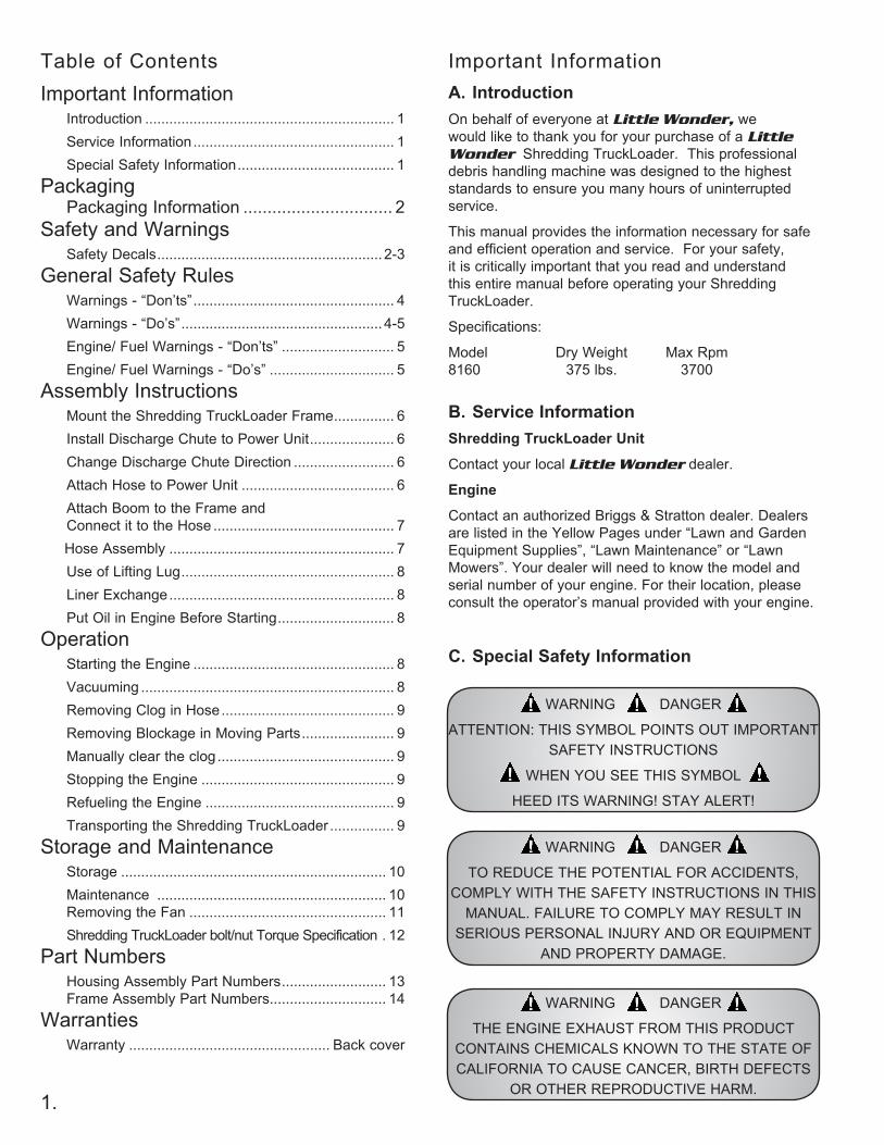
Table of Contents Important InformationA. IntroductionOn behalf of everyone at Little Wonder, we would like to thank you for your purchase of a Little Wonder Shredding TruckLoader. This professional debris handling machine was designed to the highest standards to ensure you many hours of uninterrupted service.
This manual provides the information necessary for safe and efficient operation and service. For your safety, it is critically important that you read and understand this entire manual before operating your Shredding TruckLoader.
Specifications:
Model Dry Weight Max Rpm 8160 375 lbs. 3700
B. Service InformationShredding TruckLoader Unit
Contact your local Little Wonder dealer.
Engine
Contact an authorized Briggs & Stratton dealer. Dealers are listed in the Yellow Pages under “Lawn and Garden Equipment Supplies”, “Lawn Maintenance” or “Lawn Mowers”. Your dealer will need to know the model and serial number of your engine. For their location, please consult the operator’s manual provided with your engine.
C. Special Safety Information
WARNING DANGER
ATTENTION: THIS SYMBOL POINTS OUT IMPORTANT SAFETY INSTRUCTIONS
WHEN YOU SEE THIS SYMBOL
HEED ITS WARNING! STAY ALERT!
WARNING DANGER
TO REDUCE THE POTENTIAL FOR ACCIDENTS, COMPLY WITH THE SAFETY INSTRUCTIONS IN THIS
MANUAL. FAILURE TO COMPLY MAY RESULT IN SERIOUS PERSONAL INJURY AND OR EQUIPMENT
AND PROPERTY DAMAGE.
1.
WARNING DANGER
THE ENGINE EXHAUST FROM THIS PRODUCT CONTAINS CHEMICALS KNOWN TO THE STATE OF CALIFORNIA TO CAUSE CANCER, BIRTH DEFECTS
OR OTHER REPRODUCTIVE HARM.
Important Information Introduction .............................................................. 1 Service Information .................................................. 1 Special Safety Information ....................................... 1Packaging Packaging Information ............................... 2Safety and Warnings Safety Decals ........................................................ 2-3General Safety Rules Warnings - “Don’ts” .................................................. 4 Warnings - “Do’s” .................................................. 4-5 Engine/ Fuel Warnings - “Don’ts” ............................ 5 Engine/ Fuel Warnings - “Do’s” ............................... 5Assembly Instructions Mount the Shredding TruckLoader Frame ............... 6 Install Discharge Chute to Power Unit ..................... 6 Change Discharge Chute Direction ......................... 6 Attach Hose to Power Unit ...................................... 6 Attach Boom to the Frame and
Connect it to the Hose ............................................. 7 Hose Assembly ........................................................ 7 Use of Lifting Lug ..................................................... 8 Liner Exchange ........................................................ 8 Put Oil in Engine Before Starting ............................. 8Operation Starting the Engine .................................................. 8 Vacuuming ............................................................... 8 Removing Clog in Hose ........................................... 9 Removing Blockage in Moving Parts ....................... 9 Manually clear the clog ............................................ 9 Stopping the Engine ................................................ 9 Refueling the Engine ............................................... 9 Transporting the Shredding TruckLoader ................ 9Storage and Maintenance Storage .................................................................. 10 Maintenance ......................................................... 10
Removing the Fan ................................................. 11 Shredding TruckLoader bolt/nut Torque Specification . 12Part Numbers Housing Assembly Part Numbers .......................... 13
Frame Assembly Part Numbers ............................. 14Warranties Warranty .................................................. Back cover
2.
PACKAGE LID
DISCHARGE CHUTE
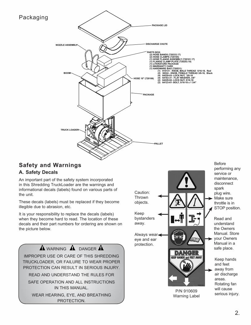
PARTS BOX: (2) HOSE BANDS (720333.17) (2) HOSE CLAMPS (720105) (1) HOSE FLANGE ASSEMBLY (720101.17) (1) FLANGE CLAMP PLATE (720253.10) (1) LITERATURE PACKAGE (1) WARRANTY CARD (1) HARDWARE BAG (720531): (1) 910131 - KNOB, MALE THREAD 5/16-18, Red (2) 38524 - KNOB, FEMALE THREAD 3/8-16, Black (4) 64229-03- LOCK NUT, 3/8-16 (4) 64163-31 - FLAT WASHER, 3/8" (2) 64229-02- LOCK NUT, 5/16-18 (2) 64123-61- BOLT, 5/16-18 x 1 3/4"
HOSE 10" (720106)
BOOM
NOZZLE ASSEMBLY
PACKAGE
PALLET
TRUCK LOADER
Packaging
P/N 910609Warning Label
Caution:Thrown objects.
Keep bystanders away.
Always wear eye and ear protection.
Before performing any service or maintenance, disconnect spark plug wire. Make sure throttle is in STOP position.
Read and understand the Owners Manual. Store your Owners Manual in a safe place.
Keep hands and feet away from air discharge areas. Rotating fan will cause serious injury.
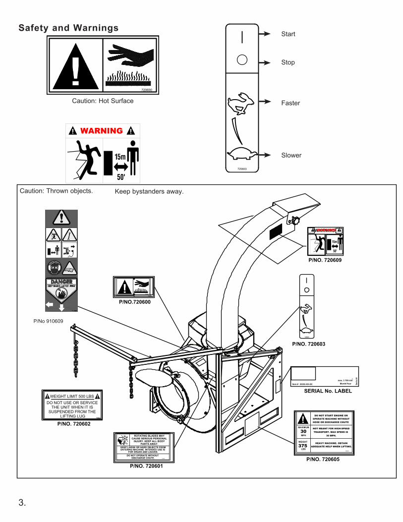
Safety and WarningsA. Safety DecalsAn important part of the safety system incorporated in this Shredding TruckLoader are the warnings and informational decals (labels) found on various parts of the unit.
These decals (labels) must be replaced if they become illegible due to abrasion, etc.
It is your responsibility to replace the decals (labels) when they become hard to read. The location of these decals and their part numbers for ordering are shown on the picture below.
WARNING DANGER
IMPROPER USE OR CARE OF THIS SHREDDING TRUCKLOADER, OR FAILURE TO WEAR PROPER PROTECTION CAN RESULT IN SERIOUS INJURY.
READ AND UNDERSTAND THE RULES FOR
SAFE OPERATION AND ALL INSTRUCTIONS IN THIS MANUAL.
WEAR HEARING, EYE, AND BREATHING PROTECTION.
3.
Safety and Warnings
Caution: Thrown objects. Keep bystanders away.
Caution: Hot Surface
WARNING
Start
Stop
Faster
Slower
max. 3 700 minMonth/YearXXXX-XX-XXItem # Se
rial #-1
P/NO.720600
P/NO. 720601
720600
720602
P/NO. 720602
720603
P/NO. 720605
P/NO. 720603
SERIAL No. LABEL
WARNING
P/NO. 720609
P/No 910609
WARNING
4.
General Safety Rules1. Read and understand manual.
2. Wear eye, hearing, and breathing protection, proper clothing and footwear.
3. While operating the machine always be sure of a safe and secure operating position, maintain a firm footing and good balance at all times.
4. Keep area clear of children, pets and bystanders.
5. Never attempt to use an incomplete machine or one fitted with an unauthorized modification.
6. Avoid contact with and inhalation of harmful fluids, gases, mists, fumes, and dust.
7. Check operation of the safety interlock switch daily. Do not defeat interlock system; it is for your protection.
8. Do not allow children to operate machine.
9. Do not override or remove any safety devices.
12. Keep hands away from hose inlet and discharge chute.
13. Disconnect spark plugs before doing any cleaning or maintenance – There are two spark plugs on the machine. Disconnect both.
14. If the Shredding TruckLoader is mounted on a trailer, make sure that the driver of the towing vehicle has the operator of the Shredding TruckLoader in full view at all times.
15. When operating the Shredding TruckLoader, operator must stay to the side of the machine, never in front or behind
16. Wear gloves to protect your hands.
17. Beware that the machine is loud and, during normal operation; may interfere with speech communication.
18. Check mounting hardware daily! When Shredding TruckLoader is attached to the Swing Away Hitch Mount, A-frame, or Tailgate, or other mounting option, beware of the possibility that the machine may overturn, fall, or tip over because of unexpected movement of the vehicle.
A. Warnings - “Don’ts”Don’t attempt to remove materials from intake or discharge when Shredding TruckLoader is running, or fan is rotating.
Don’t install or remove components while Shredding TruckLoader is running. Turn off engine to make changeover. Be sure throttle is in the stop position, and the Shredding TruckLoader has come to a complete stop. Remove the spark plug wires from the spark plug before removing material.
Don’t point the Shredding TruckLoader discharge chute in the direction of people, cars, glass, or other similar items which could be injured or damaged by blown debris.
Don’t attempt to repair Shredding TruckLoader. Have repairs made by qualified Little Wonder dealer or repairman. See that only Little Wonder and recommended engine manufacturers replacement parts are used.
Don’t leave the engine running while the Shredding TruckLoader is unattended.
Don’t store, spill, or use gasoline near flames or spark.
B. Warnings - “Do’s”Always dress properly. Do not wear loose clothing or jewelry. They can be caught in moving parts. Use of sturdy gloves, non-skid footwear and safety glasses are recommended. Always wear ear protectors where possible. Use face filter to avoid breathing dust.
Always stay alert. Watch what you are doing and use common sense. Do not operate Shredding TruckLoader when fatigued.
Always keep hands away from air intake and air outlet chute. Keep both hands on handles when power is on.
Always maintain and examine Shredding TruckLoader with care. Follow maintenance instructions given in manual.
WARNING DANGER
10. FAN COASTS AFTER THE ENGINE IS TURNED OFF.
WARNING DANGER
DO NOT SMOKE WHEN FILLING FUEL TANK
WARNING DANGER
11. ROTATING FAN. DON’T ATTEMPT TO REMOVE MATERIALS FROM INTAKE OR DISCHARGE
WHEN UNIT IS RUNNING, OR FAN IS ROTATING.
WARNING DANGERDO NOT USE THE SHREDDING TRUCKLOADER IF
THE MUFFLER IS DEFECTIVE OR MISSING.
C. Engine/ Fuel Warnings - “Don’ts”Don’t fuel, refuel or check fuel while smoking or near an open flame or other ignition source. Stop engine and be sure it is cool before refueling.
Don’t leave the engine running while the Shredding TruckLoader is unattended. Stop engine before putting the Shredding TruckLoader down or while transporting from one place to another.
Don’t start, run this TruckLoader indoors, or in an improperly ventilated area as poisonous carbon monoxide and other gasses are emitted.
5.
WARNING DANGER
IF THE SHREDDING TRUCKLOADER IS USED IMPROPERLY OR SAFETY PRECAUTIONS ARE NOT FOLLOWED, THE USER RISKS SERIOUS INJURY TO
THEMSELVES AND OTHERS.
READ AND UNDERSTAND THE FOLLOWING BEFORE ATTEMPTING TO OPERATE THIS
SHREDDING TRUCKLOADER.
WARNING DANGER
HANDLE FUEL WITH CARE. IT IS HIGHLY FLAMMABLE. FUELING A HOT ENGINE OR NEAR AN IGNITION SOURCE CAN CAUSE A FIRE AND
RESULT IN SERIOUS PERSONAL INJURY AND/ OR PROPERTY DAMAGE.
D. Engine/ Fuel Warnings - “Do’s”Always use fresh gasoline in the fuel mixture. Stale gasoline can cause leakage.
Always pull starter cord slowly until resistance is felt. Then pull cord rapidly to avoid kickback and prevent arm or hand injury.
Always operate engine with spark arrestor installed and operating properly. The use of spark arrestor mufflers is required by law in the state of California (Section 4442 of the California Public Resources Code), as well as in other states or municipalities. Federal laws apply on federal lands.
Always handle fuel with care; it is highly flammable. Never add fuel to a machine with a running or hot engine. Do not inhale fuel fumes as they are toxic.
Don’t run engine when electrical system causes spark outside the cylinder. During periodical checks of the spark plug, keep plug a safe distance from cylinder to avoid burning of evaporated fuel from cylinder.
Don’t check for spark with spark plug or plug wire removed and grounded. Use an approved tester. Sparks can ignite fumes.
Don’t run engine when the odor of gasoline is present or other explosive conditions exist.
Don’t operate the unit if gasoline is spilled. Clean up spill completely before starting engine.
Don’t refuel indoors or in an improperly ventilated area.
Don’t operate your Shredding TruckLoader if there is an accumulation of debris around the muffler, and cooling fins.
Don’t touch hot mufflers, cylinders or cooling fins as contact may cause serious burns.
B. Warnings - “Do’s” Con’tAlways store Shredding TruckLoader indoors. When not in use, store Shredding TruckLoader indoors in a sheltered area (a dry place) where it’s not accessible to children. The Shredding TruckLoader, as well as fuel, should not be stored in a house. Keep throttle in the stop position.
Always be sure Shredding TruckLoader is fully assembled. Never operate Shredding TruckLoader without all guards and defectors in place. Ensure that all nuts, bolts, screws are installed and properly tightened.
Always keep the throttle in the “stop” potion when not in use.
Always keep a safe distance between two or more operators when working together simultaneously.
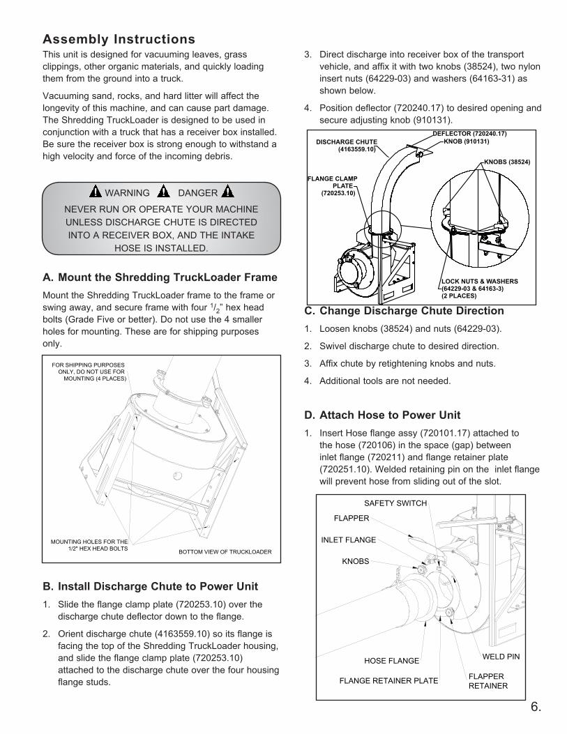
This unit is designed for vacuuming leaves, grass clippings, other organic materials, and quickly loading them from the ground into a truck.
Vacuuming sand, rocks, and hard litter will affect the longevity of this machine, and can cause part damage. The Shredding TruckLoader is designed to be used in conjunction with a truck that has a receiver box installed. Be sure the receiver box is strong enough to withstand a high velocity and force of the incoming debris.
A. Mount the Shredding TruckLoader FrameMount the Shredding TruckLoader frame to the frame or swing away, and secure frame with four 1/2” hex head bolts (Grade Five or better). Do not use the 4 smaller holes for mounting. These are for shipping purposes only.
B. Install Discharge Chute to Power Unit1. Slide the flange clamp plate (720253.10) over the
discharge chute deflector down to the flange.
2. Orient discharge chute (4163559.10) so its flange is facing the top of the Shredding TruckLoader housing, and slide the flange clamp plate (720253.10) attached to the discharge chute over the four housing flange studs.
6.
FLANGE RETAINER PLATE
HOSE FLANGE
INLET FLANGE
KNOBS
WELD PIN
FLAPPERRETAINER
FLAPPER
SAFETY SWITCH
Assembly Instructions
WARNING DANGER
NEVER RUN OR OPERATE YOUR MACHINE UNLESS DISCHARGE CHUTE IS DIRECTED INTO A RECEIVER BOX, AND THE INTAKE
HOSE IS INSTALLED.
3. Direct discharge into receiver box of the transport vehicle, and affix it with two knobs (38524), two nylon insert nuts (64229-03) and washers (64163-31) as shown below.
4. Position deflector (720240.17) to desired opening and secure adjusting knob (910131).
C. Change Discharge Chute Direction1. Loosen knobs (38524) and nuts (64229-03).
2. Swivel discharge chute to desired direction.
3. Affix chute by retightening knobs and nuts.
4. Additional tools are not needed.
D. Attach Hose to Power Unit1. Insert Hose flange assy (720101.17) attached to
the hose (720106) in the space (gap) between inlet flange (720211) and flange retainer plate (720251.10). Welded retaining pin on the inlet flange will prevent hose from sliding out of the slot.
DISCHARGE CHUTE(4163559.10)
KNOB (910131)
KNOBS (38524)
LOCK NUTS & WASHERS(64229-03 & 64163-3)(2 PLACES)
FLANGE CLAMPPLATE
(720253.10)
DEFLECTOR (720240.17)
MOUNTING HOLES FOR THE1/2" HEX HEAD BOLTS
FOR SHIPPING PURPOSES ONLY, DO NOT USE FOR
MOUNTING (4 PLACES)
BOTTOM VIEW OF TRUCKLOADER
7.
2. The flange will activate the safety switch assy (720232) that will allow you to operate the unit.
3. When hose is disconnected you can use the flapper retainer to lock the flapper in the closed position during the transportation.
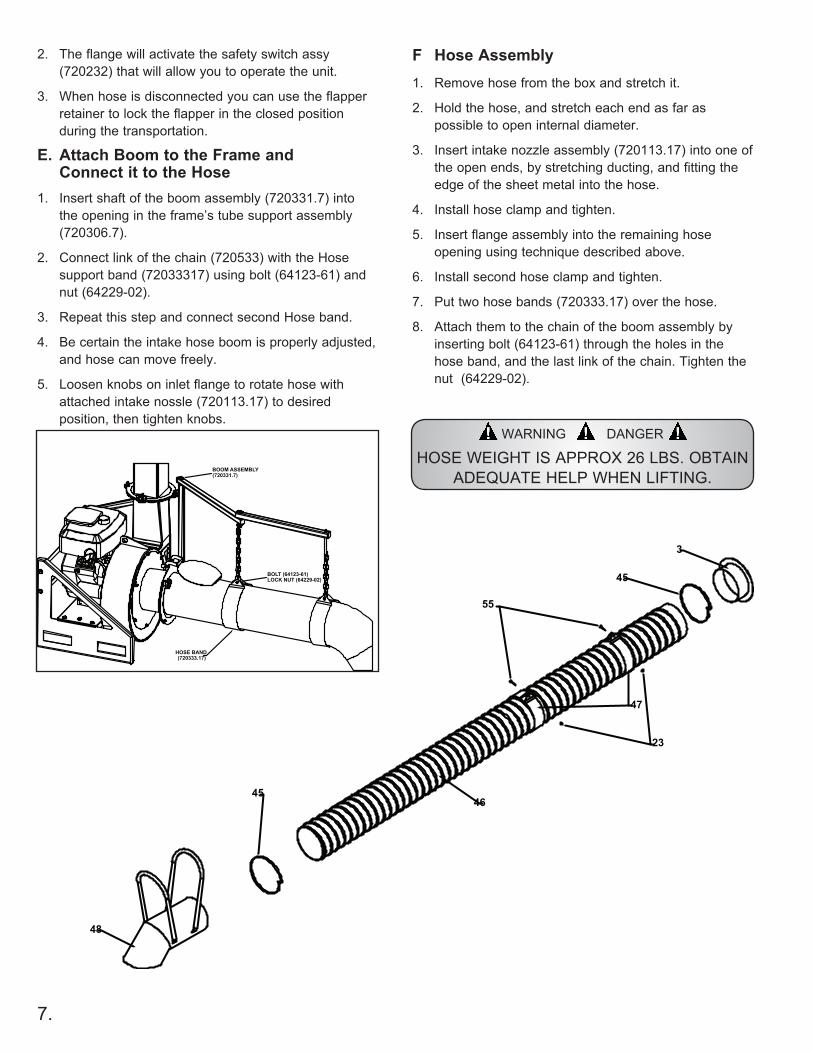
E. Attach Boom to the Frame and Connect it to the Hose
1. Insert shaft of the boom assembly (720331.7) into the opening in the frame’s tube support assembly (720306.7).
2. Connect link of the chain (720533) with the Hose support band (72033317) using bolt (64123-61) and nut (64229-02).
3. Repeat this step and connect second Hose band.
4. Be certain the intake hose boom is properly adjusted, and hose can move freely.
5. Loosen knobs on inlet flange to rotate hose with attached intake nossle (720113.17) to desired position, then tighten knobs.
HOSE BAND(720333.17)
BOOM ASSEMBLY(720331.7)
BOLT (64123-61)LOCK NUT (64229-02)
1. Remove hose from the box and stretch it.
2. Hold the hose, and stretch each end as far as possible to open internal diameter.
3. Insert intake nozzle assembly (720113.17) into one of the open ends, by stretching ducting, and fitting the edge of the sheet metal into the hose.
4. Install hose clamp and tighten.
5. Insert flange assembly into the remaining hose opening using technique described above.
6. Install second hose clamp and tighten.
7. Put two hose bands (720333.17) over the hose.
8. Attach them to the chain of the boom assembly by inserting bolt (64123-61) through the holes in the hose band, and the last link of the chain. Tighten the nut (64229-02).
45
48
4546
47
55
23
3
WARNING DANGER
HOSE WEIGHT IS APPROX 26 LBS. OBTAIN ADEQUATE HELP WHEN LIFTING.
F Hose Assembly
8.
Operation
WARNING DANGER
THE OPERATOR OF THIS SHREDDING TRUCKLOADER IS RESPONSIBLE FOR ACCIDENTS
OR HAZARDS OCCURRING TO HIMSELF, OTHER PEOPLE OR THEIR PROPERTY.
A. Starting the Engine
1. Check oil level before starting the engine.
2. Turn fuel shut-off valve to “open”.
3. Put choke control to “choke” position.
4. Move throttle control to “fast”.
5. Push on / off electrical rocker switch located on the left side of the engine to “on” position.
6. Grasp rope handle. Pull slowly until resistance is felt, then pull rapidly to start engine.
7. Let engine warm up. Slowly adjust choke toward “run” position.
B. Vacuuming1. With machine fully assembled and running, hold the
handles of the intake nozzle and move intake nozzle in sweeping motions over debris. Or rotate flange 90 degrees, put nozzle on the ground and rake the debris in the direction of the nozzle opening.
2. Move nozzle close to debris, but do not block airflow into the nozzle.
3. To increase hose life, periodically rotate flange assembly (720101.17) and reposition nozzle, so the hose will wear evenly.
WARNING DANGER
FUEL IS EXTREMELY FLAMMABLE. HANDLE IT WITH CARE. KEEP AWAY FROM IGNITION SOURCES. DO
NOT SMOKE WHILE FUELING
YOUR EQUIPMENT.
WARNING DANGER
ENGINE EMITS CARBON MONOXIDE. DO NOT OPERATE OR REFUEL IN ENCLOSED AREA.
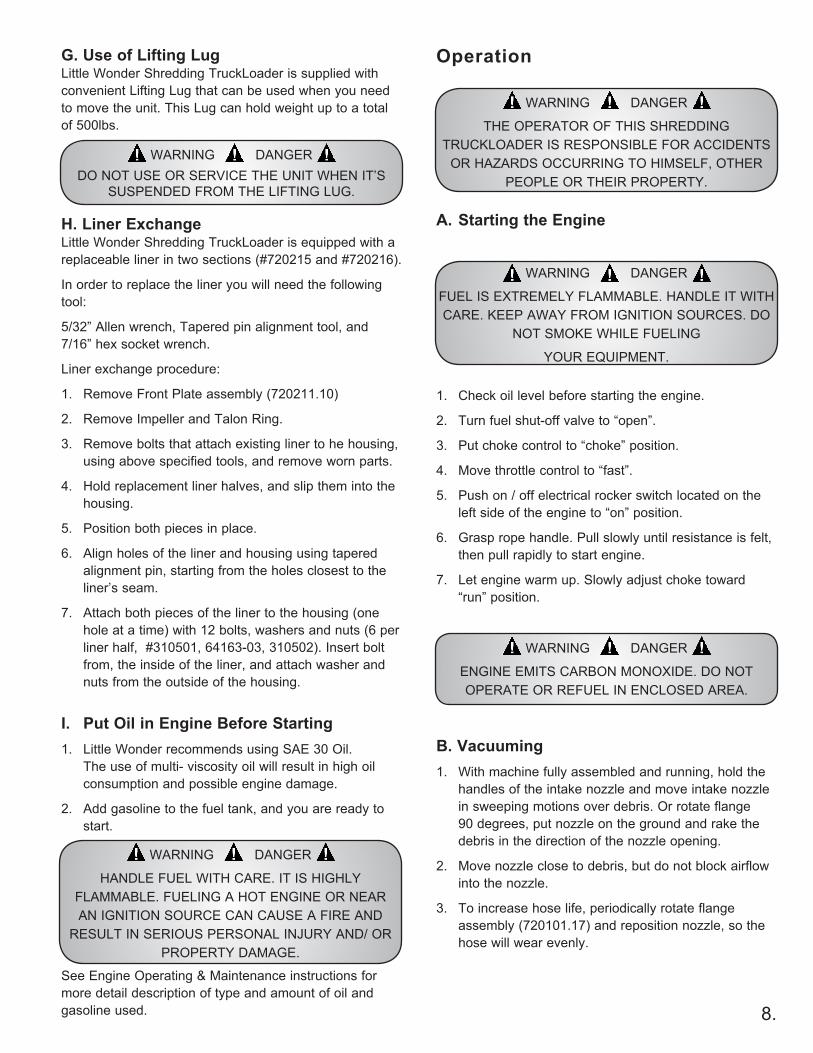
G. Use of Lifting LugLittle Wonder Shredding TruckLoader is supplied with convenient Lifting Lug that can be used when you need to move the unit. This Lug can hold weight up to a total of 500lbs.
H. Liner ExchangeLittle Wonder Shredding TruckLoader is equipped with a replaceable liner in two sections (#720215 and #720216).
In order to replace the liner you will need the following tool:
5/32” Allen wrench, Tapered pin alignment tool, and 7/16” hex socket wrench.
Liner exchange procedure:
1. Remove Front Plate assembly (720211.10)
2. Remove Impeller and Talon Ring.
3. Remove bolts that attach existing liner to he housing, using above specified tools, and remove worn parts.
4. Hold replacement liner halves, and slip them into the housing.
5. Position both pieces in place.
6. Align holes of the liner and housing using tapered alignment pin, starting from the holes closest to the liner’s seam.
7. Attach both pieces of the liner to the housing (one hole at a time) with 12 bolts, washers and nuts (6 per liner half, #310501, 64163-03, 310502). Insert bolt from, the inside of the liner, and attach washer and nuts from the outside of the housing.
I. Put Oil in Engine Before Starting1. Little Wonder recommends using SAE 30 Oil.
The use of multi- viscosity oil will result in high oil consumption and possible engine damage.
2. Add gasoline to the fuel tank, and you are ready to start.
See Engine Operating & Maintenance instructions for more detail description of type and amount of oil and gasoline used.
WARNING DANGER
HANDLE FUEL WITH CARE. IT IS HIGHLY FLAMMABLE. FUELING A HOT ENGINE OR NEAR AN IGNITION SOURCE CAN CAUSE A FIRE AND
RESULT IN SERIOUS PERSONAL INJURY AND/ OR PROPERTY DAMAGE.
WARNING DANGERDO NOT USE OR SERVICE THE UNIT WHEN IT’S
SUSPENDED FROM THE LIFTING LUG.
9.
Manually clear the clogE. Stopping the Engine1. Move throttle to “slow”.
2. Push rocker switch to “off”.
3. Close fuel shut-off valve.
F. Refueling the Engine1. Stop engine and allow it to cool for a few minutes
before refueling.
G. Transporting the Shredding TruckLoader1. Disconnect intake hose assembly from the power unit
2. Remove boom assembly from the frame, you can leave hose assembly attached to the chains of the boom.
3. Remove discharge chute.
4. Place all listed above parts in the bed of the truck and secure them with rope or hardware.
5. Before towing check safety chains for proper attachment.
WARNING DANGER
WHEN TRANSPORTING THE SHREDDING TRUCKLOADER, DO NOT EXCEED 30 M.P.H.!
HIGH-SPEED DRIVING AND POOR ROAD CONDITIONS CAN CAUSE DAMAGE TO THE UNIT.
DO NOT operate unit if excessive vibration occurs; shut engine off immediately! Remove spark plug wires and check for damaged impeller or talon ring, loose impeller bolt, loose impeller key, or lodged foreign objects.
C. Removing Clog in Hose1. Fully stretch hose in a straight line (with engine
running and unit secured).
2. If hose does not clear, use “Removing Blockage Blockage in Moving Parts” instructions below.
D. Removing Blockage in Moving Parts
WARNING DANGER
KEEP RECOIL STARTER SCREEN AND ENTIRE ENGINE CLEAR OF ALL DEBRIS. DO NOT
OPERATE ENGINE WITH AN ACCUMULATION OF GRASS, DIRT, LEAVES OR OTHER
COMBUSTIBLE MATERIAL NEAR MUFFLER.
WARNING DANGER
TURN OFF ENGINE BEFORE YOU DISCONNECT HOSE, AND MAKE SURE ALL MOVING PARTS
COME TO A COMPLETE STOP.
WARNING DANGER
BE SURE THROTTLE IS IN “STOP” POSITION, AND FAN HAS COME TO A COMPLETE STOP.
WARNING DANGER
DISCONNECT THE SPARK PLUG WIRES BEFORE ANY CLEANING OR MAINTENANCE!
WARNING DANGER
WEAR GLOVES, THE CLOG MAY CONTAIN SHARP MATERIALS.
10.
A. Storage1. When not in use store Shredding TruckLoader, in sheltered area
(a dry place) not accessible to children. Keep throttle in the “Slow” position and switch “OFF”.
2. The Shredding TruckLoader, as well as fuel, should not be stored in a house or poorly ventilated areas.
3. Do not store fuel in the engine’s gas tank longer then 30 days.
4. To prolong Hose life, store it in the sheltered area out of sunlight and out of high ambient temperatures, and where it can’t be stepped on or crushed by other objects.
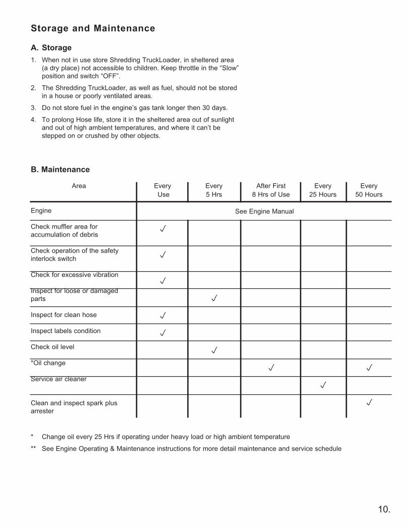
Storage and Maintenance
After First 8 Hrs of Use
p
Every Use
p
p
p
p
p
Every5 Hrs
p
p
Every 25 Hours
p
Every 50 Hours
p
p
B. Maintenance
Area
Engine
Check muffler area for accumulation of debris
Check operation of the safety interlock switch
Check for excessive vibration
Inspect for loose or damaged parts
Inspect for clean hose
Inspect labels condition
Check oil level
*Oil change
Service air cleaner
Clean and inspect spark plus arrester
See Engine Manual
* Change oil every 25 Hrs if operating under heavy load or high ambient temperature
** See Engine Operating & Maintenance instructions for more detail maintenance and service schedule
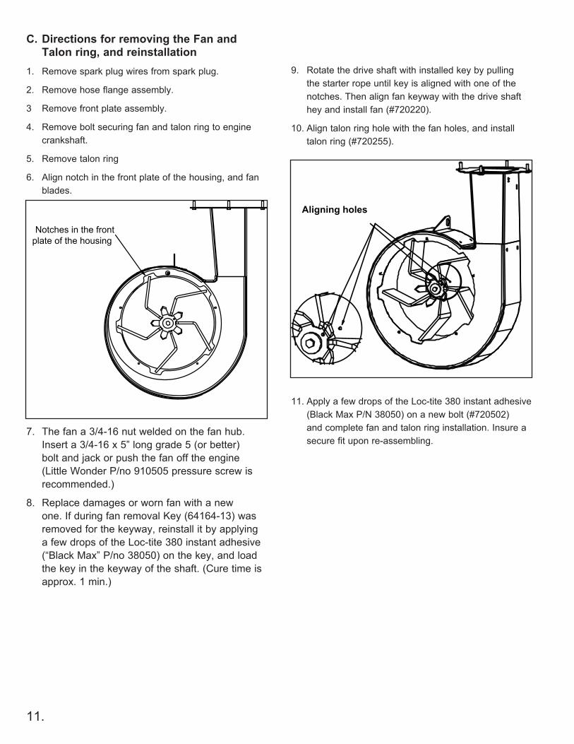
C. Directions for removing the Fan and Talon ring, and reinstallation
1. Remove spark plug wires from spark plug.
2. Remove hose flange assembly.
3 Remove front plate assembly.
4. Remove bolt securing fan and talon ring to engine crankshaft.
5. Remove talon ring
6. Align notch in the front plate of the housing, and fan blades.
7. The fan a 3/4-16 nut welded on the fan hub. Insert a 3/4-16 x 5” long grade 5 (or better) bolt and jack or push the fan off the engine (Little Wonder P/no 910505 pressure screw is recommended.)
8. Replace damages or worn fan with a new one. If during fan removal Key (64164-13) was removed for the keyway, reinstall it by applying a few drops of the Loc-tite 380 instant adhesive (“Black Max” P/no 38050) on the key, and load the key in the keyway of the shaft. (Cure time is approx. 1 min.)
11.
Notches in the frontplate of the housing
9. Rotate the drive shaft with installed key by pulling the starter rope until key is aligned with one of the notches. Then align fan keyway with the drive shaft hey and install fan (#720220).
10. Align talon ring hole with the fan holes, and install talon ring (#720255).
11. Apply a few drops of the Loc-tite 380 instant adhesive (Black Max P/N 38050) on a new bolt (#720502) and complete fan and talon ring installation. Insure a secure fit upon re-assembling.
Aligning holes
12.
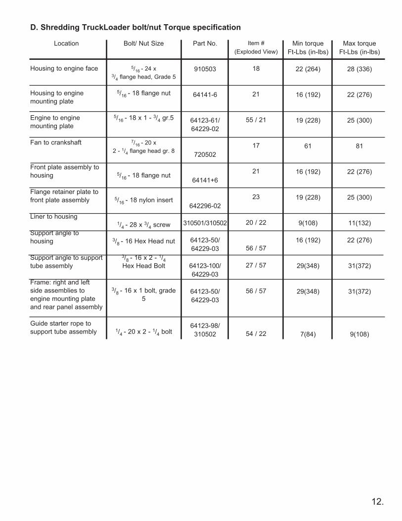
D. Shredding TruckLoader bolt/nut Torque specification
Max torqueFt-Lbs (in-lbs)
28 (336)
22 (276)
25 (300)
81
22 (276)
25 (300)
11(132)
22 (276)
31(372)
31(372)
9(108)
Item #(Exploded View)
18
21
55 / 21
17
21
23
20 / 22
56 / 57
27 / 57
56 / 57
54 / 22
Bolt/ Nut Size
5/16 - 24 x 3/4 flange head, Grade 5
5/16 - 18 flange nut
5/16 - 18 x 1 - 3/4 gr.5
7/16 - 20 x 2 - 1/4 flange head gr. 8
5/16 - 18 flange nut
5/16 - 18 nylon insert
1/4 - 28 x 3/4 screw
3/8 - 16 Hex Head nut
3/8 - 16 x 2 - 1/4 Hex Head Bolt
3/8 - 16 x 1 bolt, grade 5
1/4 - 20 x 2 - 1/4 bolt
Part No.
910503
64141-6
64123-61/64229-02
720502
64141+6
642296-02
310501/310502
64123-50/64229-03
64123-100/64229-03
64123-50/64229-03
64123-98/310502
Min torqueFt-Lbs (in-lbs)
22 (264)
16 (192)
19 (228)
61
16 (192)
19 (228)
9(108)
16 (192)
29(348)
29(348)
7(84)
Location
Housing to engine face
Housing to engine mounting plate
Engine to engine mounting plate
Fan to crankshaft
Front plate assembly to housing
Flange retainer plate to front plate assembly
Liner to housing
Support angle to housing
Support angle to support tube assembly
Frame: right and left side assemblies to engine mounting plate and rear panel assembly
Guide starter rope to support tube assembly
13.
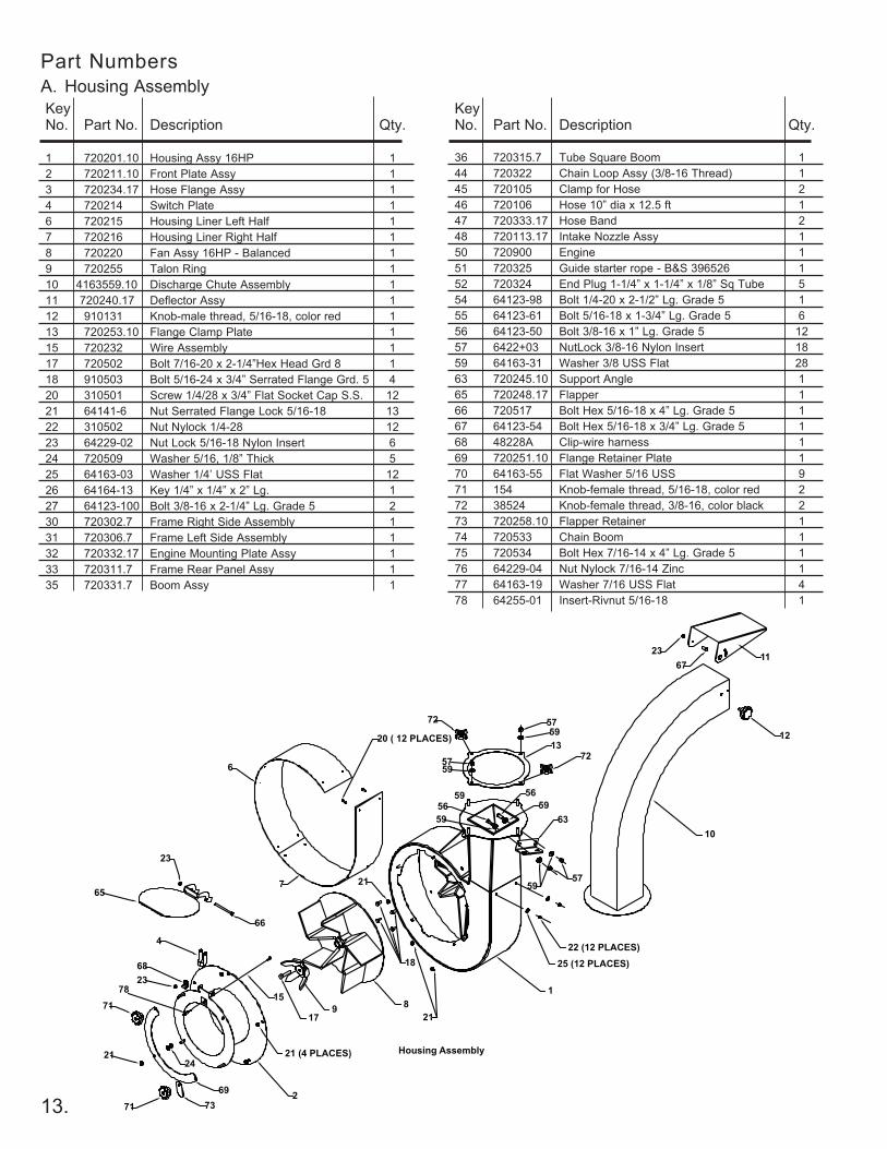
KeyNo. Part No. Description Qty.
1 720201.10 Housing Assy 16HP 12 720211.10 Front Plate Assy 13 720234.17 Hose Flange Assy 14 720214 Switch Plate 16 720215 Housing Liner Left Half 17 720216 Housing Liner Right Half 18 720220 Fan Assy 16HP - Balanced 19 720255 Talon Ring 110 4163559.10 Discharge Chute Assembly 111 720240.17 Deflector Assy 112 910131 Knob-male thread, 5/16-18, color red 113 720253.10 Flange Clamp Plate 115 720232 Wire Assembly 117 720502 Bolt 7/16-20 x 2-1/4”Hex Head Grd 8 118 910503 Bolt 5/16-24 x 3/4” Serrated Flange Grd. 5 420 310501 Screw 1/4/28 x 3/4” Flat Socket Cap S.S. 1221 64141-6 Nut Serrated Flange Lock 5/16-18 1322 310502 Nut Nylock 1/4-28 1223 64229-02 Nut Lock 5/16-18 Nylon Insert 624 720509 Washer 5/16, 1/8” Thick 525 64163-03 Washer 1/4’ USS Flat 1226 64164-13 Key 1/4” x 1/4” x 2” Lg. 127 64123-100 Bolt 3/8-16 x 2-1/4” Lg. Grade 5 230 720302.7 Frame Right Side Assembly 131 720306.7 Frame Left Side Assembly 132 720332.17 Engine Mounting Plate Assy 133 720311.7 Frame Rear Panel Assy 135 720331.7 Boom Assy 1
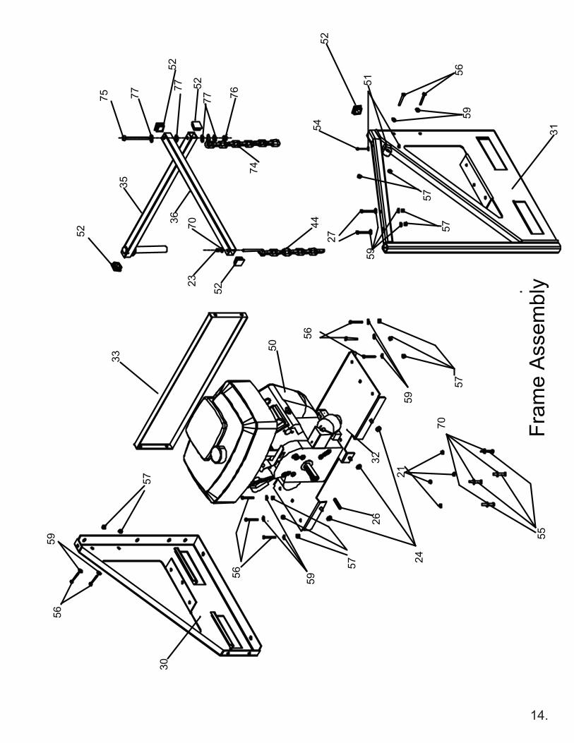
KeyNo. Part No. Description Qty.
36 720315.7 Tube Square Boom 144 720322 Chain Loop Assy (3/8-16 Thread) 145 720105 Clamp for Hose 246 720106 Hose 10” dia x 12.5 ft 147 720333.17 Hose Band 248 720113.17 Intake Nozzle Assy 150 720900 Engine 151 720325 Guide starter rope - B&S 396526 152 720324 End Plug 1-1/4” x 1-1/4” x 1/8” Sq Tube 554 64123-98 Bolt 1/4-20 x 2-1/2” Lg. Grade 5 155 64123-61 Bolt 5/16-18 x 1-3/4” Lg. Grade 5 656 64123-50 Bolt 3/8-16 x 1” Lg. Grade 5 1257 6422+03 NutLock 3/8-16 Nylon Insert 1859 64163-31 Washer 3/8 USS Flat 2863 720245.10 Support Angle 165 720248.17 Flapper 166 720517 Bolt Hex 5/16-18 x 4” Lg. Grade 5 167 64123-54 Bolt Hex 5/16-18 x 3/4” Lg. Grade 5 168 48228A Clip-wire harness 169 720251.10 Flange Retainer Plate 170 64163-55 Flat Washer 5/16 USS 971 154 Knob-female thread, 5/16-18, color red 272 38524 Knob-female thread, 3/8-16, color black 273 720258.10 Flapper Retainer 174 720533 Chain Boom 175 720534 Bolt Hex 7/16-14 x 4” Lg. Grade 5 176 64229-04 Nut Nylock 7/16-14 Zinc 177 64163-19 Washer 7/16 USS Flat 478 64255-01 Insert-Rivnut 5/16-18 1
1
4
6
7
8 9
10
11
12
17
18
20 ( 12 PLACES)
21
21 59
63
22 (12 PLACES) 25 (12 PLACES)
6723
23
65
66
15
2
23
69
2124
Housing Assembly 21 (4 PLACES)
68
71
71
57
72
13
5957 72
5957
5956
5956
73
59
78
Part NumbersA. Housing Assembly
14.
70
32
30
55
26
2457
21
5956
56
57
59
35
52
59
31
70
59
57
44
59
33
56
23
57
57
27
56
52
51
50
Fram
e A
ssem
bly
54
74
52
52
75
77
77
5277 76
36
LITTLE WONDER®Schiller Grounds Care, Inc.
1028 STREET ROAD, P.O. BOX 38SOUTHAMPTON, PA 18966
PHONE 877-596-6337 • FAX 215-357-8045www.littlewonder.com
Specifications, descriptions, and illustrative material in this literature are as accurate as known at the time of publication, but are subject to change without notice.
P/N 416330105/2009
8 7 7 - L W O N D E R
WARNING DANGER
THE ENGINE EXHAUST FROM THIS PRODUCT CONTAINS CHEMICALS KNOWN TO THE STATE OF CALIFORNIA TO CAUSE CANCER, BIRTH DEFECTS
OR OTHER REPRODUCTIVE HARM.
2 yEAR LIMITED SERVICE & WARRANTy POLICy FOR GASOLINE POWERED
FOR SHREDDING TRUCkLOADER
The LittLe Wonder Shredding TruckLoader is guaranteed against defects in material and workmanship for a period of TWO YEARS from date of purchase, when used for RESIDENTIAL SERVICE, or COMMERCIAL SERVICE. Any LittLe Wonder Shredding TruckLoader or part found to be defective within the warranty period is to be returned to any registered LittLe Wonder Dealer.
Engines for all gasoline powered products are warranted separately by the engine manufacturer. Therefore, there are no warranties made, expressed or implied, for engines for gasoline powered products by LittLe Wonder.
Transportation charges for parts and units submitted for replacement under this warranty must be borne by the purchaser.
THIS WARRANTY shall not be effective if the product has been subject to misuse, negligence or accident, or if the product has been repaired or altered outside of our Southampton factory or authorized repair facility in any respect which affects its condition or operation.
LittLe Wonder shall not be liable for any special indirect or consequential damages arising from defective equipment. Any implied warranty, including merchantability of fitness for a particular purpose, shall not extend beyond the written warranty period.
THIS WARRANTY shall only be effective if the enclosed Warranty/Registration card is properly filled out and returned to LittLe Wonder, Div. of Schiller Grounds Care, Inc. at time of purchase.