Embed Size (px)
Citation preview

LITTLE WONDER®
OWNER’S MANUAL and SAFETY INSTRUCTIONSfor Single Edged (Models 1910, 2410, 3010, 1912, 2412, 3012)
and Double Edged (Models 1920, 2420, 3020, 1922, 2422, 3022)Electric Hedge Trimmers
EN WARNING DANGERBLADES ARE EXTREMELY SHARP.
TO AVOID INJURY WHEN UNPACKING THE HEDGE TRIMMER,
DO NOT GRASP THE BLADES.
!!
MANUAL DEL PROPIETARIO e INSTRUCCIONES DESEGURIDAD
para las unidades con una sola cuchilla (modelos 1910, 2410, 3010, 1912, 2412, 3012) y las unidades con dos cuchillas (modelos 1920, 2420, 3020, 1922, 2422, 3022)
Podadora de arbustos eléctrica
ES ADVERTENCIA PELIGROLAS CUCHILLAS ESTÁN
EXTREMADAMENTE FILOSAS. PARAEVITARSE UNA LESIÓN AL DESEMPACAR
LA PODADORA DE ARBUSTOS, NO LASOSTENGA POR LAS CUCHILLAS.
!!
MANUEL DE L’UTILISATEUR et INSTRUCTIONS DESÉCURITÉ
à tranchant unique (modèles 1910, 2410, 3010, 1912, 2412 et 3012)et à double tranchant (modèles 1920, 2420, 3020, 1922, 2422 et 3022)
Taille-haies électriques
FR AVERTISSEMENT DANGERLES LAMES SONT EXTRÊMEMENT
COUPANTES. POUR ÉVITER DE SE BLESSERPENDANT LE DÉBALLAGE DE L’APPAREIL,
NE PAS LE SAISIR PAR LA LAME.
!!

TABLE OF CONTENTSPage
I. IMPORTANT INFORMATION
A. Introduction .......................................................................................................2
II. GENERAL SAFETY RULES ...........................................................................................3A. Safety Decals......................................................................................................4B. Safety Symbols Identification ...........................................................................4C. Special Safety Rules ..........................................................................................5D.Warnings — Dont’s ............................................................................................5E. Warnings — Do’s................................................................................................5
III. UNPACKING AND ASSEMBLY INSTRUCTIONS .............................................................6
IV. OPERATIONA. Instructions for Proper Operation ................................................................6-7
V. MAINTENANCEA. Lubrication.........................................................................................................7B. Service Maintenance Guide ..............................................................................7
VI. SERVICEA. Trouble Shooting ...............................................................................................8B. Blade Adjustment...............................................................................................8
VII. PARTS EXPLOSIONS............................................................................................9-13
VII. SPECIFICATIONS....................................................................................BACK COVER
LIMITED SERVICE & WARRANTY POLICY.......................................................Back Cover
I. IMPORTANT INFORMATION
A. INTRODUCTION
On behalf of everyone at Little Wonder, wewould like to thank you for your purchase of aLittle Wonder Electric Powered HedgeTrimmer. This professional trimming machinewas designed to the highest standards to ensureyou many hours of uninterrupted service.
This manual provides the informationnecessary for safe and efficient operation andservice. For your safety, it is criticallyimportant that you read and understand thisentire manual before operating your hedgetrimmer.
2

3
Warning: When using electric tools, basic safetyprecautions, including the following, should always befollowed to reduce the risk of fire, electric shock andpersonal injury.
Read all these instructions before operating thisproduct and save these instructions.
For safe operations:1) Keep work area clean.
Cluttered areas and benches invite injuries.2) Consider work area environment.
Do not expose power tools to rain. Do not usepower tools in damp or wet locations. Keep workarea well lit. Do not use power tools where thereis risk of fire or explosion.
3) Guard against electric shock.Avoid body contact with earthed or groundedsurfaces e.g. pipes, radiators, ranges, refrigerators.
4) Keep children away.Do not let visitors touch the tool or extensioncord. All visitors should be kept away from area.
5) Store idle tools. When not in use, tools should be stored in a dry,high or locked up place, out of reach of children.
6) Do not force the tool.It will do the job better and safer at the rate forwhich it was intended.
7) Use the right tool.Do not force small tools or attachments to do thejob of a heavy duty tool. Do not use tools forpurposes not intended; for example, do not usecircular saws to cut tree limbs or logs.
8) Dress properly.Do not wear loose clothing or jewelry, the can becaught in moving parts. Rubber gloves and non-skid footwear are recommended when workingoutdoors. Wear protective hair covering to containlong hair.
9) Use safety glasses.Use face or dust mask if the cutting operation isdusty.
10) Do not abuse the cord.Never carry the tool by the cord or yank it todisconnect if from the socket. Keep the cord awayfrom heat, oil and sharp edges.
11) Secure work.Use a vice to clamp the frame bar while adjustingblades. It is safer than using your hand and it freesboth hands to operate the tools.
12) Do not overreach.Keep proper footing and balance at all times.
13) Maintain tool with care.Keep cutting tools sharp and clean for better andsafer performance. Follow instructions forlubrication and changing accessories. Inspect toolcord periodically and if damaged have it repairedby an authorized service facility. Inspect extensioncords periodically and replace, if damaged. Keephandles dry, clean and free from oil and grease.
14) Disconnect tools.When not in use, before servicing and whenchanging accessories such as blades, bits andcutters.
15) Remove adjusting keys and wrenches.Form the habit of checking to see that keys andadjusting wrenches are removed from the toolbefore turning it on.
16) Avoid unintentional starting.Do not carry a plugged in tool with a finger on theswitch. Ensure switch is off when plugging in.
17) Use outdoor extension leads.When tool is used outdoors, use only extensioncords intended for outdoor use.
18) Stay alert.Watch what you are doing . Use common sense.Do not operate tool when you are tired.
19) Check damaged parts.Before further use of the tool, a guard or other partthat is damaged should be carefully checked todetermine that it will operated properly andperform its intended function. Check foralignment of moving parts, free running of movingparts, breakage of parts, mounting and any otherconditions that may affect its operation. A guardor other part that is damaged should be properlyrepaired or replaced by an authorized servicecenter unless otherwise indicated in thisinstruction manual. Have defective switchesreplaced by an authorized service facility. Do notuse the tool if the switch does not turn it on andoff.
20) Warning.The use of any accessory or attachment, otherthan those recommended in this instructionmanual, may present a risk of personal injury.
21) Have your tool repaired by a qualified person.This electric tool conforms to relevant safetyrequirements. Repairs should only be carried outby qualified persons using original spare parts,otherwise this may result in considerable dangerto the user.
II. GENERAL SAFETY RULES

WARNING DANGERIF TRIMMER IS USED IMPROPERLY OR SAFETY PRECAUTIONS ARE NOT FOLLOWED,
THE USER RISKS SERIOUS INJURY TO THEMSELVES AND OTHERS. READ AND UNDERSTAND THE RULES FOR SAFE OPERATION AND ALL
INSTRUCTIONS IN THIS MANUAL.
A. SAFETY DECALS AND MOLDED SYMBOLS
Important parts of the safety system incorporated inboth Single Edge and Double Edge trimmers are thewarning and informational decals and molded-insymbols found on various parts of the trimmer. Thesedecals must be replaced in time due to abrasion, etc.
It is your responsibility to replace the decals or moldedhousing when they become hard to read. The locationsof these safety features are shown below. See page 13for their part numbers when ordering replacements.
4
B. SAFETY SYMBOLS IDENTIFICATION
Single Edge Trimmer Double Edge Trimmer
Guard
Serial Number decalSide Handle
Rear Handle
On/Off Switches
Loop Handle
Guard
On/Off Switch On/Off Switch
Safety Symbols (Molded into Part No. 310400 Main Housing Set}
Rear Handle
WHAT THE SYMBOLS MEAN:1. Read the instructions.2. Do not expose to rain.3. Remove plug from main (electric
power source) immediately if cable isdamaged or cut.
4. Double insulated.
1 2 3 4
WARNING DANGERTO REDUCE THE POTENTIAL FORACCIDENTS, COMPLY WITH THESAFETY INSTRUCTIONS IN THIS
MANUAL. FAILURE TO COMPLY MAYRESULT IN SERIOUS PERSONAL
INJURY AND OR EQUIPMENT ANDPROPERTY DAMAGE.
WARNING DANGERTHIS SYMBOL POINTS OUT
IMPORTANT SAFETY INSTRUCTIONS.
WHEN YOU SEE THIS SYMBOL, HEED IT’S WARNING!!
STAY ALERT!!
! !
!
! !
!
!
! !

C. SPECIAL SAFETY RULES
1. Read and understand the owner’s manual. Payparticular attention to all sections regarding safety.
2. Always keep a firm grip on both handles while theblades are moving and/or the motor is running. OnSingle Edged units, the right hand grasps the frontside handle and the left hand grasps the rear handle.On Double Edged units, one hand grasps the front‘loop’ handle, while the other hand grasps the rearhandle.
BE AWARE!! The blades coast after triggers arereleased or motor is switched off. Make sure bladeshave come to a complete stop before letting go of ahandle.
3. Maintain a firm footing and good balance; do notoverreach while trimming. Before you start to trim,check the work area for obstacles that might causeyou to lose your footing, balance or control of themachine.
4. Keep area clear of children, pets, and bystanders.
D. WARNINGS — DON’TS
Don’t use trimmer with one hand, keep both hands onhandles with fingers and thumbs encircling the handles,while blades are moving, and motor is running.
Don’t overreach or stand on unstable support. Do notstand on the top of a ladder while trimming. Use properequipment for reaching higher heights. Keep a goodfooting at all times.
Don’t ever grasp cutting blades for any reason.
Don’t attempt to clear cut material while blades aremoving, and the motor is running. Never try to remove
jammed material before switching the motor off andmaking sure the blades have stopped completely.
Don’t over-ride safety features.
Don’t allow children or incapable people to operate thistrimmer.
Don’t operate this hedge trimmer while under theinfluence of alcohol or drugs.
Don’t attempt to repair this hedge trimmer. Haverepairs made by a qualified dealer or repairman. Seethat only original Little Wonder parts are used.
5
E. WARNINGS — DO’S
Always read and follow all instructions.
Always stay alert. Watch what you are doing and usecommon sense. Do not operate unit when fatigued.
Always dress properly. Do not wear loose clothing orjewelry, they might get caught in moving parts. Usesturdy proper fitting, non-slip gloves. Gloves reduce thetransmission of vibration to your hands. Prolongedexposure to vibration can cause numbness and otherailments. Wear non-skid foot wear to ensure secure andproper footing.
Always wear ear and eye protection. Eye protectionmust meet ANSI Z 87.1. To avoid hearing damage werecommend hearing protection be worn whenever usingthe equipment.
Always keep both hands on both handles whentrimmer is running. Severe injuries can result if youtry to use the hedge trimmer with only one hand orwith an insecure grip.
Always keep children, pets, and incapable personsaway.
Always use trimmer properly. Cut only types and sizeof growth described in the Trimming section of thismanual. Overloading or abusing your hedge trimmercan cause premature failure and can result in injury.Use common sense.
Always keep a safe distance between two or moreoperators when working together simultaneously.
Always inspect your unit before each use and ensurethat all handles, guards, safety devices and fasteners aresecure, operating, and in place.
Always maintain and examine your trimmer with care.Follow maintenance instructions given in manual.
Always store trimmer in a sheltered area (a dry place)not accessible to children. The hedge trimmer shouldnot be stored in a house.
!
!
!

A. INSTRUCTIONS FOR PROPER OPERATION
WARNING DANGERBLADES COAST AFTER RELEASING THE
SWITCHES
KEEP A FIRM GRIP WITH ONE HANDON EACH HANDLE WHILE BLADES ARE
MOVING AND/OR MOTOR ISRUNNING.
DO NOT STAND ON THE TOP OF ALADDER WHILE TRIMMING.
MAKE SURE YOUR LADDER OR OTHERSUPPORT IS STABLE AND ON FIRM
GROUND.
KEEP A SURE FOOTING.DO NOT OVERREACH.
IF YOUR TRIMMER BECOMES JAMMED,TURN OFF THE HEDGE TRIMMER.
MAKE SURE BLADES HAVE STOPPEDCOMPLETELY, THEN REMOVE
THE OBSTRUCTION.
III. UNPACKING AND ASSEMBLY INSTRUCTIONS
WARNING DANGER
BLADES ARE EXTREMELY SHARP. TOAVOID INJURY WHEN UNPACKING THEHEDGE TRIMMER, DO NOT GRASP THE
BLADES.
Your Little Wonder hedge trimmer has beenassembled for you at the factory. Before operating be
sure all fasteners are secure, and all guards and safetydevices are in place and operating properly.
WARNING DANGER
IF YOU HAVE ANY QUESTIONS,CONTACT YOUR LOCAL DEALER
IV. OPERATION
WARNING DANGERTHE OPERATOR OF THIS HEDGE TRIMMER IS RESPONSIBLE FOR
ACCIDENTS OR HAZARDS OCCURRING TO HIMSELF, OTHERPEOPLE OR THEIR PROPERTY.
6
Misuse of this Hedge Trimmer will void the warranty.ie: cutting hedges or shrubs over 1/2" in diameter orforeign objects such as wires, rocks, or fences. Beforetrimming check work area for foreign objects such aswires, cords, glass, fences, or rocks. Be sure to removeany foreign objects from the work area. Failure toproperly maintain this hedge trimmer will void thewarranty.
! !
!!
!!
!!Securing the
extension cord.Bend the extensioncord about 6" fromthe plug end. Pushthat bend throughthe oblong openingin the back of thehandle. Then loopthe bend under thecord retaining clipsas shown. This willprevent the extensioncord from detachingfrom the hedgetrimmer plug.

V. MAINTENANCE
1. Read care and safety instructions carefully beforeattempting to use this trimmer. Only after you arefamiliar with your hedge trimmer and all of its controlsand the functions should you start the trimmer.
2. Before plugging into an electric circuit, be sure that thevoltage supply is as specified on hedge trimmer. Models 1910, 1920, 2410, 2420, 3010, 3020 are rated at464 watts at 115 volts. Models 1912, 1922, 2412, 2422, 3012, 3022 are rated at390 watts at 230 volts.
3. Be sure the switches are in the “off” (not depressed)position before connecting unit to the applicablecurrent. (120V AC or 220V/240V AC.) Do not carry aplugged -in trimmer with a finger on the switch.
4. The electricity for this hedge trimmer should besupplied through a Residual Current Device (RCD) witha tripping current of not more than 30 mA. Theseprotective devices are also known as Residual CurrentCircuit Breakers (RCCBs) or Earth Leakage CircuitBreakers (ELCBs).
5. Keep extension cord behind trimmer. Never drape
extension cord over hedge being trimmed. On 120Vunits, use 16 gauge wire extension cord up to 100 feet.Over 100 feet use 14 or heavier gauge wire or extensioncord. Cords are available from your local Little Wonderdealer. The use of light gauge lamp cords or sizes lighterthan those specified above will result in loss of power,possible motor failure, overheating of cord and thepossibility of fire.
6. Warning! These trimmers have been designed so theycan only be operated when using both hands. Do notattempt to override this important safety feature in anyway.
7. Hold trimmer firmly. For Single Edge Model, keep righthand on side handle and left hand on rear handle. ForDouble Edge Model, you can place either hand on eitherhandle. Squeeze both switches.Tilt trimmer so cutting tooth is angled slightly towardthe hedge or shrub and proceed to cut. Use overlapping sweeping motions away from your body toachieve a safe and even cut. The unit is designedto cut any type of hedge or shrub; however,thickness of cut should not exceed 1/2 inch in diameter.
1/2"
Remove the plug from the socket before carrying out any adjustment, servicing, or maintainence.
B. SERVICE MAINTENANCE GUIDE
Area
Gear HousingBladesFastenersLabelsHandlesGuards / Safety Devices
Maintenance
Check GreaseInspect / Clean / LubricateInspect / Tighten / ReplaceInspect / ReplaceInspect / ReplaceInspect / Replace
Frequency
MonthlyAfter Each UseBefore Each UseBefore Each UseBefore Each UseBefore Each Use
IMPORTANT- Time intervals shown are maximum. Actual use and your experience will determine thefrequency of required maintenance. 7
1. A few drops of light (#10) oil should be placed onthe back edge of each blade at each adjustingscrew after approximately every four hours ofnormal operation.
2. To obtain trouble free trimming, it is necessary tokeep the blades lubricated and clean. The gumthat collects and builds up on the blades can beremoved with 50-50 mixture of kerosene and #10oil. Since a petroleum product can shorten the lifeof some plastics, it is necessary to remove excessoil-kerosene mixture from the plastic parts. Bladesmust be clean before they can be adjusted.Caution! Kerosene and oil are flammable.
3. A few drops of light (#10) or 3-in-1 oil should beput in the hole indicated on the bottom coverplate. This is necessary only at the beginning of aday’s operation.
4. Gear housing and motor bearings have beenpermanently lubricated with a special greasewhich should last for the life of the trimmer. Whenblades are replaced, or any other time that thebottom cover plate is removed, the grease must bechecked for proper amount (approximately 3/4 fullin the area of the gears), and a new gasket and newscrews must be used to insure proper seating ofcover plate. Use only Lubrico M3-3K9K grease(P/N 16-78A) in the gear housing. Lubrico M24M(P/N 16-78B) is to be used on the motor bearings.Lubrico is available through your local LittleWonder Dealer.
5. Before each use, inspect to be sure handles, safetydevices and fasteners are secure and in place, andcord is not frayed. If the supply cord is damaged, itmust be replaced by the manufacturer, its serviceagent or similarly qualified person in order toavoid a hazard.
A. LUBRICATION AND MAINTENANCE

WARNING DANGERKEEP HANDS AWAY FROM THE BLADES WHILE SERVICING THE HEDGE TRIMMER.
BE SURE TRIMMER IS SECURED, UNPLUGGED, AND BLADES ARE GUARDED WHILE MAKING ADJUSTMENTS
The care and adjustment of the blades is very importantto the efficient operation of the trimmer and especiallyto the long life of the motor.
Make sure the trimmer is NOT plugged in.
1. Turn trimmer upside down. Place trimmer in vice,clamping on the sides of frame bar. Be careful!Blades are sharp!
2. Using a 7/16” wrench, loosen all blade locknutsand unscrew the large head screws by two turns.
3. Starting with the screw nearest the gear housing,tighten the screw until the blade guard of the
Single Edged trimmer or the protective comb of the Double Edged trimmer can just be moved withfinger pressure. (A .0015" (1 1/2 thou.) feeler gaugejust slips under the blade guard or comb whenproperly adjusted.) Tighten the locknuts whileholding the screw stationary in its correct adjustedposition. Re-check to make sure the blade guard orcomb can still be moved.
4. Repeat Step 3 on each screw in turn until all arecorrectly adjusted.
NOTE: CORRECT BLADE ADJUSTMENT CANONLY BE ACHIEVED ON CLEAN, OILED BLADES.
B. BLADE ADJUSTMENT
8
A. TROUBLE SHOOTING
Problem
1. Blades don’t cut cleanly.
2. Blades don’t move whenturned on.
3. Excessive electrical arcingfrom vents in top oftrimmer.
Remedy
Have blades sharpened andadjusted.
Re-adjust blades followingservice instructions.
Replace brushes - followservice instructions.
Cause
Blades are dull or not adjustedproperly.
Blades are adjusted too tight.
Worn brushes.
VI. SERVICE
! !
DOUBLE EDGEDSINGLE EDGED
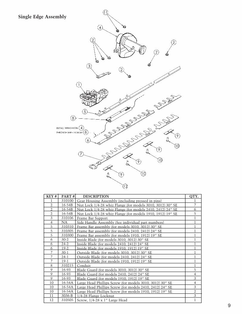
Single Edge Assembly
9
KEY # PART # DESCRIPTION QTY.1 310100 12 16-54B 72 16-54B 62 16-54B 53 310106 14 NA 15 310310 15 310305 15 310300 16 30-2 16 24-2 16 19-2 17 30-1 17 24-1 17 19-1 18 310215 19 16-93 59 16-93 49 16-93 3
10 16-54A 410 16-54A 310 16-54A 211 3036-B 312 310505 1
Gear Housing Assembly (including pressed in pins)Nut Lock 1/4-28 whiz Flange (for models 3010, 3012) 30” SENut Lock 1/4-28 whiz Flange (for models 2410, 2412) 24” SENut Lock 1/4-28 whiz Flange (for models 1910, 1912) 19” SEFrame Bar SupportSide Handle Assembly (See individual part numbers)Frame Bar assembly (for models 3010, 3012) 30” SEFrame Bar assembly (for models 2410, 2412) 24” SEFrame Bar assembly (for models 1910, 1912) 19” SEInside Blade (for models 3010, 3012) 30” SEInside Blade (for models 2410, 2412) 24” SEInside Blade (for models 1910, 1912) 19” SEOutside Blade (for models 3010, 3012) 30” SEOutside Blade (for models 2410, 2412) 24” SEOutside Blade (for models 1910, 1912) 19” SEConduitBlade Guard (for models 3010, 3012) 30” SEBlade Guard (for models 2410, 2412) 24” SEBlade Guard (for models 1910, 1912) 19” SELarge Head Phillips Screw (for models 3010, 3012) 30” SELarge Head Phillips Screw (for models 2410, 2412) 24” SELarge Head Phillips Screw (for models 1910, 1912) 19” SE1/4-28 Flange LocknutScrew, 1/4-28 x 1” Large Head
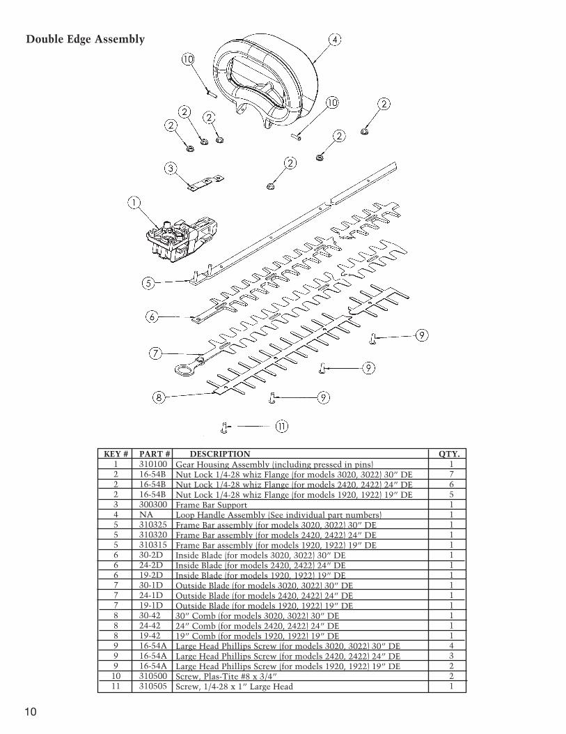
Double Edge Assembly
10
KEY # PART # DESCRIPTION QTY.1 310100 12 16-54B 72 16-54B 62 16-54B 53 300300 14 NA 15 310325 15 310320 15 310315 16 30-2D 16 24-2D 16 19-2D 17 30-1D 17 24-1D 17 19-1D 18 30-42 18 24-42 18 19-42 19 16-54A 49 16-54A 39 16-54A 210 310500 211 310505 1
Gear Housing Assembly (including pressed in pins)Nut Lock 1/4-28 whiz Flange (for models 3020, 3022) 30” DENut Lock 1/4-28 whiz Flange (for models 2420, 2422) 24” DENut Lock 1/4-28 whiz Flange (for models 1920, 1922) 19” DEFrame Bar SupportLoop Handle Assembly (See individual part numbers)Frame Bar assembly (for models 3020, 3022) 30” DEFrame Bar assembly (for models 2420, 2422) 24” DEFrame Bar assembly (for models 1920, 1922) 19” DEInside Blade (for models 3020, 3022) 30” DEInside Blade (for models 2420, 2422) 24” DEInside Blade (for models 1920, 1922) 19” DEOutside Blade (for models 3020, 3022) 30” DEOutside Blade (for models 2420, 2422) 24” DEOutside Blade (for models 1920, 1922) 19” DE30” Comb (for models 3020, 3022) 30” DE24” Comb (for models 2420, 2422) 24” DE19” Comb (for models 1920, 1922) 19” DELarge Head Phillips Screw (for models 3020, 3022) 30” DELarge Head Phillips Screw (for models 2420, 2422) 24” DELarge Head Phillips Screw (for models 1920, 1922) 19” DEScrew, Plas-Tite #8 x 3/4”Screw, 1/4-28 x 1” Large Head

Gear/Motor Assembly
11
KEY # PART # DESCRIPTION QTY.1 310100 12 16-57A 13 310407 44 D16-71 15 16-62 16 D16-59 17 16-64 18 16-65 19 16-67 110 16-81-1 811 310503 212 3042 413 D16-56F 114 310903 114 310900 115 310108 117 16-69D 118 310901 118 310902 119 16-69E 120 3025 221 310105 222 3026 2
Gear Housing AssemblyGear Housing Cover PlateGrommet RubberGasket Cover PlateEccentric GearCluster GearConnecting RodSpacer Connecting RodFeltScrew 6-32 x 5/16Motor Bolt 8-32 x 2 1/2Machine ScrewWear PlateStator 120V (For Models 3020, 3010, 2420, 2410, 1920, 1910)Stator 230V (For Models 3022, 3012, 2422, 2412, 1922, 1912)Motor Housing Base and Cap Set with Brush HolderBearing LowerArmature 120V (For Models 3020, 3010, 2420, 2410, 1920, 1910)Armature 230V (For Models 3022, 3012, 2422, 2412, 1922, 1912)Bearing UpperBrush Holder (not shown)BrushBrush Retaining Plate

Double Edge Front Loop Handle Assembly
Single Edge Front Handle Assembly
12
KEY # PART # DESCRIPTION QTY.1 3033 12 310405 13 310219 14 310203 15 310207 16 310504 37 310500 28 310218 1
Switch Normally OpenSwitch Normally ClosedLoop Handle Trigger SetLoop Handle SetShieldScrew Plasti-Tite #8 x 1”Screw Plasti-Tite #8 x 3/4”Loop Handle Trigger Strap
KEY # PART # DESCRIPTION QTY.1 310206 12 310210 13 3033 14 310405 15 310502 16 310501 17 310500 38 310200 1
Side Handle ShieldTrigger Side HandleSwitch Normally OpenSwitch Normally ClosedNut Nylock 1/4-28Socket Flat Head 1/4-28 x 3/4 ssScrew Plasti-Tite #8 x 3/4”Side Handle Set

Main Housing Assembly
13
KEY # PART # DESCRIPTION QTY.1 310400 12 310403 13 310404 15 310438 15 310436 15 310439 15 310437 16 310209 17 3033 18 310405 19 310500 6
10 310504 311 310410 111 310412 112 310600 113 310217 1
Main Housing SetHousing Brush Cap Cover PlateHousing Loop Handle Cover Plate *PC Board Assembly (for Models 3012, 2412, 1912)PC Board Assembly (for Models 3010, 2410, 1910)PC Board Assembly (for Models 3022, 2422, 1922)PC Board Assembly (for Models 3020, 2420, 1920)Trigger Rear HousingSwitch Normally OpenSwitch Normally ClosedScrew, Plasti-tite #8 x 3/4”Screw, Plasti-tite #8 x 1”120V Cord Assembly230V Cord AssemblyWarning LabelGrommet, Conduit **
* Not needed for double edge models.** Not needed for single edge models.

LIMITED SERVICE & WARRANTY POLICY FOR ELECTRIC HEDGE TRIMMERS
All Little Wonder Electric Hedge Trimmers are guaranteed against defects in material andworkmanship for a period of 2 YEARS from date of purchase, when used for RESIDENTIAL SERVICE, or 1 Year when used for COMMERCIAL SERVICE. Any Little Wonder Electric Hedge Trimmer or partfound to be defective within the warranty period is to be returned to any registered Little Wonder Dealer.
Transportation charges for parts and units submitted for replacement under this warranty must beborne by the purchaser.
THIS WARRANTY shall not be effective if the product has been subject to misuse, negligence oraccident, used in cutting hedges or shrubs greater than 1/2" in diameter, used to cut foreign objectssuch as wire, rocks, or fences, or if the product has been repaired or altered outside of our Southamptonfactory or any registered Little Wonder dealer, in any respect which affects its condition or operation.
LITTLE WONDER shall not be liable for any special indirect or consequential damages arising fromdefective equipment. Any implied warranty, including merchantability of fitness for a particularpurpose, shall not extend beyond the written warranty period.
THIS WARRANTY shall only be effective if the enclosed Warranty/Registration card is properly filledout and returned to Little Wonder, Div. of Schiller-Pfeiffer, Inc. at time of purchase.
Manufactured by:
LITTLE WONDER®
DIVISION OF SCHILLER-PFEIFFER, INCORPORATED1028 STREET ROAD, P.O. BOX 38
SOUTHAMPTON, PA 18966PHONE 215-357-5110 • FAX 215-357-8045
Specifications. descriptions, and illustrative material in this literature are as accurate as known at the time of publication, but are subject to change without notice.
©2003, LITTLE WONDER, Division Schiller-Pfeiffer, Inc. P/N 3107001-03
VIII. SPECIFICATIONS
Model Cutting Length Weightcm (in.) kg (lb)
1912 48 (19) 3.49 (7.7)1922 48 (19) 3.89 (8.6)2412 61 (24) 3.62 (8.0)2422 61 (24) 4.04 (8.9)3012 76 (30) 3.85 (8.5)3022 76 (30) 4.59 (10.1)
All listed hedge trimmers are rated for 230 volts AC at 50 hertz.
The A-weighted emission sound pressure levelat the operator position has been measured at:LPA = 80 dB(A). These measurements weremade in accordance with EN ISO 11201:1996under no-load conditions.
The Hand-Arm weighted r.m.s. vibrationmeasured at the handles in accordance withEN 50144-1 part 13.3 at rated conditions, noload was:1.0 m/s2.