Embed Size (px)
Citation preview

MOBISERV – FP7 248434 An Integrated Intelligent Home Environment for the
Provision of Health, Nutrition and Mobility Services to the
Elderly
Final Deliverable
D5.4: Multi-sensor system integrated into wearable fabrics
Date of delivery: Month 38
Contributing Partners: CSEM, SMARTEX
Date: March 2013 Version: v1.2

D5.4: Multi-sensor system integrated into wearable fabrics 2/42
MOBISERV FP7 248434
Document Control
Title: D5.4: Multi-sensor system integrated into wearable fabrics
Project: MOBISERV (FP7 248434)
Nature: Prototype Dissemination Level: Restricted
Authors: CSEM - SMARTEX
Origin: CSEM
Doc ID: MOBISERV_WEARABLE_PLATFORM_USER_MANUAL
Amendment History
Version Date Author Description/Comments
V1.0 2013-02-10 Marc Correvon (CSEM)
Tommaso Faetti (SMARTEX)
First version
V1.1 2013-03-05 Herjan van den Heuvel (SMH) Reviewed for submission,
added comments.
V1.2 2013-04-11 Marc Correvon (CSEM) Modification according
comments (see V1.1). Major
modification sections 6.2
and 6.3.
The information contained in this report is subject to change without notice and should not be construed as a commitment by any members of
the MOBISERV Consortium. The MOBISERV Consortium assumes no responsibility for the use or inability to use any software or
algorithms, which might be described in this report. The information is provided without any warranty of any kind and the MOBISERVConsortium expressly disclaims all implied warranties, including but not limited to the implied warranties of merchantability and fitness for a
particular use.

D5.4: Multi-sensor system integrated into wearable fabrics 3/42
MOBISERV FP7 248434
Table of contents GLOSSARY .............................................................................................................................. 7
1 INTRODUCTION AND FEATURES ................................................................................ 8
1.1 EXECUTIVE SUMMARY ................................................................................................. 8
1.2 GENERAL OVERVIEW ................................................................................................... 8
1.3 STRUCTURE OF THE DOCUMENT .................................................................................. 9
2 GARMENTS ..................................................................................................................... 10
2.1 DESIGN OF THE NEW PROTOTYPES ............................................................................ 10
2.2 DAY GARMENTS ......................................................................................................... 10
2.3 NIGHT GARMENTS ..................................................................................................... 14
3 MOBISERV ANTTM
MODULE FOR TEMPERATURE MONITORING ..................... 17
3.1 HARDWARE DESCRIPTION .......................................................................................... 17
3.2 SPECIFICATIONS ......................................................................................................... 17
3.2.1 System Specifications ........................................................................................... 17
3.2.2 Measurement Channels Specifications ................................................................ 18
3.2.3 ANTTM
Channel description ................................................................................. 18
3.2.4 Data Format......................................................................................................... 19
4 DATA LOGGER............................................................................................................... 21
4.1 HARDWARE DESCRIPTION .......................................................................................... 21
4.2 MICRO-SD CARD MEMORY ........................................................................................ 21
4.3 CONNECTORS ............................................................................................................. 22
4.3.1 USB ...................................................................................................................... 22
4.3.2 Sensor jack ........................................................................................................... 22
4.4 SPECIFICATIONS ......................................................................................................... 22
4.4.1 System specification ............................................................................................. 22
4.4.2 Data logger specifications ................................................................................... 23
4.4.3 Extracted parameters specifications .................................................................... 24
4.4.4 Power consumption versus operating mode ........................................................ 24
4.5 OPERATING MODES .................................................................................................... 24
4.5.1 Mode Description................................................................................................. 24
4.5.2 Mode control ........................................................................................................ 25
4.5.2.1 Mode switch and status indicator .......................................................................................................... 25
4.5.2.1.1 Description ......................................................................................................................................... 25
4.6 MONITORING SIGNS AND DATA PROCESSING ............................................................ 26
5 WHSU SOFTWARE PACKAGE ..................................................................................... 28
5.1 BUILDING BLOCKS ...................................................................................................... 28
5.2 BLOCKS SPECIFICATION ............................................................................................ 28
5.3 DEVICE ....................................................................................................................... 29
5.4 DEVICEMANAGER ...................................................................................................... 29
5.5 DOWNLOADMANAGER ............................................................................................... 29
5.6 SESSIONMANAGER ..................................................................................................... 29
5.7 VIEWER ...................................................................................................................... 29
5.8 SESSION STORAGE ...................................................................................................... 29
5.9 INTEGRATION INTO KOMPAÏ ROBOT ........................................................................ 29

D5.4: Multi-sensor system integrated into wearable fabrics 4/42
MOBISERV FP7 248434
6 WHSU MULTI-PARAMETER ACQUISITION SYSTEM ............................................ 31
6.1 INTRODUCTION........................................................................................................... 31
6.2 MOBISER DATA LOGGER SERVER ............................................................................. 32
6.3 EXERCISES MANAGER ............................................................................................... 33
7 ELECTROMAGNETIC COMPATIBILITY .................................................................... 35
7.1 WARNING ................................................................................................................... 35
7.2 GUIDANCE AND MANUFACTURER’S DECLARATION – EMC EMISSIONS ................... 35
7.3 GUIDANCE AND MANUFACTURER’S DECLARATION – EMC IMMUNITY .................... 35
7.4 RECOMMENDED SEPARATION DISTANCES ................................................................. 37
7.5 COMPLIANT CABLES AND ACCESSORIES .................................................................... 38
7.6 ESSENTIAL PERFORMANCES ...................................................................................... 38
8 GETTING STARTED....................................................................................................... 39
9 MAINTENANCE AND CARE ........................................................................................ 41
9.1 GENERAL GUIDANCE FOR THE GARMENT .................................................................. 41
9.2 GENERAL GUIDANCE FOR THE DATA LOGGER .......................................................... 41
9.2.1 Cleaning and chemicals ....................................................................................... 41
9.3 DISCLAIMERS ............................................................................................................. 41
9.3.1 User’s responsibility ............................................................................................ 41
9.3.2 Warnings .............................................................................................................. 41
9.4 DISPOSAL OF DEVICE ................................................................................................. 42

D5.4: Multi-sensor system integrated into wearable fabrics 5/42
MOBISERV FP7 248434
Table of Figures
Figure 1: Direct connection with secondary user ...................................................................... 8
Figure 2: Direct connection with secondary user ...................................................................... 9
Figure 3: The sketch of the female (a) and male (b) day shirt ................................................. 11
Figure 4: The visual label with instructions for the correct use of shirts ................................. 12
Figure 5: The final prototypes of female (left) and male (right) vest ...................................... 12
Figure 6: The four textile electrodes in the inner side of the female shirt ............................... 13
Figure 7 The inner side (left) and outer side (right) of the band .............................................. 13
Figure 8 The Male/Female sketch of the nightgown ............................................................... 14
Figure 9 The label inserted in the nightgown .......................................................................... 15
Figure 10 One of the two conductive cuffs with the integrated temperature sensor ............... 15
Figure 11 Female version of the nightgown ............................................................................ 16
Figure 12 MOBISERV ANT module with the housing........................................................... 17
Figure 13: Data logger overview ............................................................................................. 21
Figure 14: Collaborating components of WHSU..................................................................... 28
Figure 15: Collaborating components of Exercises when integrated into Kompaï robot ........ 30
Figure 16: Interaction between the PC software parts and the Mobiserv Data Logger ........... 31
Figure 17: Starting Mobiserv Data Logger Server .................................................................. 32
Figure 18: Message telling a successful start of the Mobiserv Data Logger Server ................ 32
Figure 19: Procedure to wet the electrodes .............................................................................. 39
Figure 20: Plugging the connector on the garments ................................................................ 39
Figure 21: Switching on the electronic .................................................................................... 39
Figure 22: Placing the electronic inside the band and T-shirt ................................................. 40
Figure 23: Turning on the ANT module .................................................................................. 40
Figure 24: Plugging the ERNI connector on the pyjama ......................................................... 40

D5.4: Multi-sensor system integrated into wearable fabrics 6/42
MOBISERV FP7 248434
List of Tables
Table 1 System specifications .................................................................................................. 17
Table 2 Module Specifications ................................................................................................ 18
Table 3 ANTTM
Channel Description ...................................................................................... 18
Table 4 Global Data Message Format ..................................................................................... 19
Table 5 ANTTM
Message Payload ........................................................................................... 19
Table 6: General characteristics ............................................................................................... 22
Table 7: Data logger characteristics ......................................................................................... 23
Table 8: Characteristics of the local extracted parameters ...................................................... 24
Table 9: Operating mode description ....................................................................................... 24
Table 10: Selectable mode by the mode switch ....................................................................... 25
Table 11: Selectable mode by the mode switch ....................................................................... 25
Table 12: Communication channels, acquired signals (raw data) ........................................... 26
Table 13: Communication channels, algorithm channels (processed data) ............................. 26
Table 14: Quality index ........................................................................................................... 27
Table 15: Activity classification .............................................................................................. 27
Table 16: Services offered by the Server to control the data logger ........................................ 33
Table 17: Messages and handler of the exercises manager MRDS service ............................. 33
Table 18: – Electromagnetic emission – .................................................................................. 35
Table 19: – Electromagnetic immunity – ................................................................................. 36
Table 20: Recommended separation distances ........................................................................ 38
Table 21: List of compliant cables and accessories ................................................................. 38

D5.4: Multi-sensor system integrated into wearable fabrics 7/42
MOBISERV FP7 248434
Glossary Term Explanation MOBISERV An Integrated Intelligent Home Environment for the Provision of Health,
Nutrition and Mobility Services to the Elderly
2D 2 dimensional
3D 3 dimensional
AAL Ambient Assisted Living
ADL Activities of Daily Living
AES Advanced Encryption Standard
BNs Bayesian networks
BR Breathing rate
DES Data Encryption Standard
DESL DES Lightweight
ECG Electrocardiogram
FVQ Fuzzy Vector Quantization
GPRS General Packet Radio Service
GPS Global Positioning System
HR Heart Rate
HRV Heart Rate Variability
IPsec Internet Protocol Security
LDA Linear Discriminant Analysis
MMSE Mini Mental State Examination
MPEG-7 Moving Picture Experts Group
ORU Optical Recognition Unit
PRU Physical Robotic Unit
PSTN Public switched telephone network
PTD Personal Trusted Device
RFID Radio Frequency Identification
SHACU Smart Home Automation and Communication Unit
SIFT Scale-invariant feature transform
SLAM Simultaneous localization and mapping
SVM Support Vector Machines
TLS Transport Layer Security
UCD User-centred design
UTAUT Unified Theory of Acceptance and Use of Technology
WHSU Wearable Health Supporting Unit
WIPR Weizmann-IAIK Public-Key for RFID

D5.4: Multi-sensor system integrated into wearable fabrics 8/42
MOBISERV FP7 248434
1 Introduction and features 1.1 Executive summary This document accompanies the actual / “physical” prototypes of the MOBISERV Wearable
Health Supporting Unit (WHSU) (shirt and band for daily use, pyjamas for night use,
together with a data logger and an application on PC). It aims at providing general
information about the prototype(s) and to briefly explain how they work.
1.2 General overview The WHSU can be used in two different configurations. The first one concerns the direct use
with secondary user; that means without the need of the complete MOBISERV infrastructure.
The two actors are the patient and the healthcare professional. The figure below shows the
configuration needed.
Figure 1: Direct connection with secondary user
This configuration can be used in the hospital or during a medical examination and does not
need any intervention from the patient.
The second configuration is the complete system involving the PRU, the SHACU and the
WSHU. This configuration is used daily at home. The difference between the two
configurations is the application on PC. The viewer for the secondary user allows the
visualization of the whole set of vital signs and extracted parameters in real time while the
second configuration is a full long term monitoring of the patient in his/her daily life.
The data logger monitors vital signs (ECG and respiration), activity (3-axis acceleration) and
physiological extracted parameters, which are Heart rate (HR), Breathing rate (BR), activity
classification (lying, standing, walking, running and others). All the data can be recorded
(daily or nightly sessions) in a removable SD memory card (recording mode) or / and sent in
real time via Bluetooth to a PC (streaming mode). All recorded vital sign and processed data
can be downloaded via USB link while the data logger is recharging. It is a convenient,
economical way for later review of the recorded information.

D5.4: Multi-sensor system integrated into wearable fabrics 9/42
MOBISERV FP7 248434
Figure 2: Direct connection with secondary user
1.3 Structure of the document This document is organized as follows. The first chapter provides a general overview of the
system and possible configurations. The second chapter is dedicated to the description of the
daily and nightly application and the garment that is used in each case. The third chapter is
devoted to the technical description of the body sensor network based on ANT technology.
The fourth chapter describes the data logger in terms of hardware specifications and
maintenance. The fifth chapter gives an overview of the monitoring infrastructures for both
the secondary user environment and with the Robot and the SHACU. Chapter six gives the
necessary information to install the application on PC for the secondary user as well as a
short description of how to use the viewer. Chapter 7 gives some indications on the data
logger and the compliance with electrical and safety standard for medical devices. Chapter 8
provides a “getting started” description for the user himself. Finally, chapter 9 is advice
guideline related to the care and maintenance of the hardware (garment and embedded
electronics).

D5.4: Multi-sensor system integrated into wearable fabrics 10/42
MOBISERV FP7 248434
2 Garments Within the scope of MOBISERV two different types of garments have been created for vital
signs monitoring: the first one refers to sensorized shirt and band for day use, and the second
one to nightgown for night use. The garments have been deeply evaluated several times
during the project and revised accordingly, following suggestions and remarks carried out by
experts, carers and finally end-users in an iterative approach.
Following the delivery of the first set of wearable prototypes (D 5.3), an extensive evaluation
of WHSU has been conducted in 2012 in four stages:
• co-operative evaluation with carers,
• expert review by a care expert,
• co-design evaluation sessions with older adults,
• home trials.
The results are described in D2.5 Issue II - Appendix 3. The outcomes of this evaluation
study have been deeply discussed among the involved partners to start a second refinement
process. On the garment side, the changes were fundamentally focused on ergonomic,
comfort and usability aspects. The goal: to deliver a set of final prototypes as close as
possible to the elderly needs. No changes were made on the number and type of sensors
integrated into the textiles given to the fact that they can be considered sufficient for the
proposed scenarios.
In the following chapters the final prototypes of garments are presented and described. Care
and maintenance guide together with instructions for the correct use of the garments can be
found in chapters 8 and 9.
2.1 Design of the new prototypes The main issues and remarks raised during the evaluation trials can be summarized as
follows:
• Users could be disoriented and confused by using the WHSU
• In the night systems, people can be confused by the use of the two data-loggers
• Pyjamas were not easy to be worn due to a lack of a front opening
• Elderly in general prefer to not wear lower part of pyjamas during the night
• The pockets of the garments didn't prevent the data-logger to coming out, especially
while sleeping
• People were afraid to damage the garments while washing them
• Temperature sensors and cables could be scaring and not comfortable for users
• People have difficulties to understand which is the inner part of the band
Generally, positive feedbacks were given on the chosen materials (mainly cotton based
yarns), and the use of zip and Velcro®.
2.2 Day Garments Before starting the development of the new wearable systems, some sketches were designed
and submitted to the expert partners to eventually check some inconsistency.
Figure 3 presents the sketches for the day garments.

D5.4: Multi-sensor system integrated into wearable fabrics 11/42
MOBISERV FP7 248434
Figure 3: The sketch of the female (a) and male (b) day shirt
The improvements to the final prototypes of shirts can be resumed in the following list of
bullets:
• Pockets are now closed by Velcro®.
• A colour code to clearly bind the type of electronics with the pocket and connector is
used to avoid confusion.
• A label with visual instruction for the correct use is applied to the shirts.
• A label with info on size, materials and washing instructions is applied to the shirts
• Removable long/short sleeves are added to the shirts to customize the dressing and to
increase thermal comfort
• Textile electrodes are integrated into an adjustable strip to enhance the fitting of the
sensing part to the user
The shirts are made with cotton fabric that is one of the preferred materials by elderly people.
As the previous prototypes, both shirts and band presents:
a) four textile electrodes placed on the chest region to detect ECG (1 Lead) and
respiration through bio impedance measurements,
b) one custom connector to plug the electronic,
c) a pocket to house the electronic during use,
d) a Velcro® fastening for the band and a zip for the shirts.
A label with visual instructions for the correct use of the shirts has been designed to facilitate
the users in the wearing of the shirts. The label is shown in Figure 4:

D5.4: Multi-sensor system integrated into wearable fabrics 12/42
MOBISERV FP7 248434
Figure 4: The visual label with instructions for the correct use of shirts
A very simple label assists the user by means of four basic steps, during the use of the
WSHU. The final prototypes of shirts for female and male are illustrated in Figure 5 and
Figure 6.
Figure 5: The final prototypes of female (left) and male (right) vest

D5.4: Multi-sensor system integrated into wearable fabrics 13/42
MOBISERV FP7 248434
Figure 6: The four textile electrodes in the inner side of the female shirt
The day garments collection also includes a band that can be used during a short time
window, for instance just to monitor an exercises session during the day.
The band could help to overcome possible lacks in acceptability by the users that do not want
to wear the sensorized shirt for the whole day.
The band has been improved by:
• Redesigning pocket to increase ergonomics and comfort.
• Using different colours for the inner and outer side of the band to avoid confusion.
• Inserting a label with visual instructions for the correct use.
• Inserting a label with info on size, materials and washing instructions.
Capital letters L and R has been inserted into the bands to facilitate orientation when wearing
it.
The inner and outer side of the band are shown in Figure 7
Figure 7 The inner side (left) and outer side (right) of the band

D5.4: Multi-sensor system integrated into wearable fabrics 14/42
MOBISERV FP7 248434
2.3 Night Garments As for the day garments also night monitoring system has been completely redesigned to
include all recommendations made by the users and by the experts within the evaluation
trials. In particular, the idea to have a pyjama has been abandoned and replaced by a
nightgown that seems to be easier worn and more accepted by elderly in general.
A first sketch of the night garments has been designed and submitted to experts. The sketch is
shown in figure 6.
Figure 8 The Male/Female sketch of the nightgown
As a result the following list of bullets describes the improvements made with respect to
previous pyjamas prototypes:
• Pyjamas are replaced by nightgown to increase comfort and usability.
• Pockets are closed by Velcro® to prevent electronics to slide out while sleeping.
• A colour code to clearly bind the type of electronics with the pocket and connector is
used to avoid confusion.
• A label with visual instruction for the correct use is applied to the nightgown.
• A label with info on size, materials and washing instructions is applied to the
nightgown
• Velcro fastening on wrist is not comfortable and is replaced by elastic rib
• Temperature sensor is inserted into a soft pocket and it could be glued to avoid
discontinuity between metal and skin
• The fastening on Nightgown is now similar to the one used in the shirts to let the user
to be able to fully open it.

D5.4: Multi-sensor system integrated into wearable fabrics 15/42
MOBISERV FP7 248434
The label for nightgown also contains the instructions to correctly use the ANT data logger
for temperature monitoring, as shown in figure 7.
Figure 9 The label inserted in the nightgown
Two textile electrodes are available as conductive cuffs (see Figure 10). An elastic material
together with a cord lock system has been inserted in order to let the user adjust and optimize
the skin/electrode contact without losing comfort. The chosen sensor is the same commercial
thermistor of the previous prototypes, which gives reliable information with a 0.1 degree of
accuracy. One sensor has been integrated into the nightgown, inside the cuff. The choice of
the location is aiming at two different goals: to maintain comfort for the user on one side, and
to guarantee a good contact with the skin in order to reach a thermal equilibrium with the
body on the other side. The chosen region seems to be the best trade-off between reliable
information and comfort for the user.
Figure 10 One of the two conductive cuffs with the integrated temperature sensor

D5.4: Multi-sensor system integrated into wearable fabrics 16/42
MOBISERV FP7 248434
A specific ANTTM
module has been designed to interface properly the sensors as explained in
chapter 3.
Nightgown presents:
a) Two textile electrodes placed on the cuffs that can be used to detect ECG and are
adjustable by means of elastic ribs.
b) One thermistor inserted into the cuff.
c) One custom connector to plug the main electronic.
d) One ERNI connector to plug the ANTTM
temperature module.
e) Two pockets to house both the electronics during the sleep.
Figure 11 Female version of the nightgown

D5.4: Multi-sensor system integrated into wearable fabrics 17/42
MOBISERV FP7 248434
3 MOBISERV ANTTM Module for temperature monitoring
A wireless module has been specifically designed to measure the resistance of the thermistors
that are integrated in the nightgown to monitor the skin temperature of the subject. No
changes have been made on this side with respect to the previous prototypes.
3.1 Hardware description MOBISERV ANT
TM
module provides the following accessories:
− one 3-pin ERNI connector for the thermistors,
− one on/off switch,
− one status led blinking when transmitting.
Figure 12 MOBISERV ANT module with the housing
3.2 Specifications
3.2.1 System Specifications
An overview of the general characteristics of the MOBISERV ANTTM
module is listed in
Table 1.
Table 1 System specifications
Characteristics
Power management
Battery CR 2430, 3V Lithium coin cell (disposable)
Battery capacity 280 mAh
Autonomy
Autonomy while
streaming Up to 560 hours
Temperature
Operating 0 to 50 °C

D5.4: Multi-sensor system integrated into wearable fabrics 18/42
MOBISERV FP7 248434
Characteristics
Storage -20 to 50 °C
Humidity Operational up to 95% non-condensing
Communication interface
Wireless ANTTM
wireless module ANT11TS33M5IB
Certifications FCC Test ready (CFR47), RHOS compliant
Device
Dimensions 41 x 41 x 23mm
Weight 27 gr.
3.2.2 Measurement Channels Specifications
The developed module has been designed with two identical analogue front-ends to measure
the resistance of the sensors. All the characteristic of the hardware channels are summarized
in Table 2.
Table 2 Module Specifications
Characteristics
Temperature Front Ends (2 identical)
Type of measurement Two wires DC measurement
Range 22400 Ω to 42388 Ω
Bandwidth DC to 0.5 Hz
ADC Sampling rate 32 Hz
ADC Resolution 16 bits
3.2.3 ANTTM
Channel description
The module offers ANTTM
connectivity acting as a Master and sending messages in broadcast
mode, in order to have lower power consumption according to ANTTM
specifications in
SensRcore™ mode1. Two modules have been developed in this prototype. They can be
distinguished by different RF frequency offset. The ANTTM
channel configuration parameters
are listed in Table 3.
Table 3 ANTTM
Channel Description
ANTTM Channel Configuration
Device ID
Device Number 1 Unique ANTTM
device number
Device type 1 Unique ANTTM
device type
1 Please visit www.thisisant.com for further details on protocol specifications

D5.4: Multi-sensor system integrated into wearable fabrics 19/42
MOBISERV FP7 248434
ANTTM Channel Configuration (pairing bit disabled)
Transmission Type 1
No shared address, Global
Data Identification Byte
present
Network configurations
Channel type 0x10 Bidirectional Master Transmit
Channel
Channel Period 16384 2 Hz Message Rate
Network number 0 Default public network
Message Rate 2 Hz Message Rate
RF Frequency Offset 0 MHz for module 1
72 MHz for module 2
Default Frequency 2400 MHz
Default Frequency 2472 MHz
3.2.4 Data Format
3 different data channels, more precisely the cuff sensor, abdominal sensor and battery
voltage, are assigned to the physical ANT channel specified by Device ID parameters listed
in Table 3. The data are transmitted according to ANT SensRcore™ Global Data Message
Format that is reported in Table 4, in which Global Data identification byte value is 0x41
(analogue data).
Table 4 Global Data Message Format
Data 0 Data 1 Data 2 Data 3 Data 4 Data 5 Data 6 Data 7
Global Data
Identification
Byte
Global
Defined
Data 1
Global
Defined
Data 2
Global
Defined
Data 3
Global
Defined
Data 4
Global
Defined
Data 5
Global
Defined
Data 6
Global
Defined
Data 7
Table 5 shows the significance of transmitted bytes:
Table 5 ANTTM
Message Payload
ANT Message Payload Byte
Parameters Type Range Description
Global Data Byte 3 Analogue Signal Source UCHAR 0..255
Indicates signal source:
0x00 --> Temp sensor 1
(hip sensor)
0x01: Temp sensor 2
(cuff sensor)
0xFF: Battery Voltage
Global Data Byte 4 Max (8-bit) UCHAR 0..255
8 most significant bits of
the maximum recorded
analogue level

D5.4: Multi-sensor system integrated into wearable fabrics 20/42
MOBISERV FP7 248434
ANT Message Payload Byte
Parameters Type Range Description
Global Data Byte 5 Min (8-bit) UCHAR 0..255
8 most significant bits of
the minimum recorded
analogue level
Global Data Byte 6-
7 Measured A/D Data USHORT 0..65536
The measured A/D data
from the analogue signal
(LSB first)
The measured A/D data represents the voltage drop across the thermistor. In order to
calculate the corresponding resistance value the following conversion must be applied to the
data value:
= 0.305 ∙ + 22400Ω
Once the resistance value is calculated, the Steinhart-Hart equation can be used to estimate
the corresponding value of temperature (Kelvin degrees):
1
= + ∙ + ∙ lnln
where A = -6.151082E-3, B = 1.2127443E-3 and C = -2.8552001E-6

D5.4: Multi-sensor system integrated into wearable fabrics 21/42
MOBISERV FP7 248434
4 Data logger 4.1 Hardware description The first version of the MOBISERV data logger has been updated with the integration of an
ANT module used for the wireless body array network. In the first version, the respiration
sensor was a strain gauge, in this second version, there is the possibility to use either a strain
gauge or the impedance plethysmography measurement. CSEM has redesigned the user
interface by adding 4 LEDs. The jack connector is now integrated into the housing in order to
increase ergonomics. The embedded signal processing has been improved. This version of
MOBISERV data logger provides the following features:
− one 4-pin jack connector for textile sensors (ECG and IPG or strain gauge),
− one USB connector for configuration and data transfer,
− one micro-SD memory card slot,
− four status light,
− one mode switch,
− one reset switch accessible through a hole.
Figure 13: Data logger overview
4.2 Micro-SD card memory The device records data into a micro-SD card memory. The device will immediately stop
recording if the memory is removed while in operation. Please note that only the provided
2GB micro-SD Card (reference: Scandisk SDSDQ-002G-E11M or Kingston SDC/2GB) have
been fully tested. No support for other brands or memory models can be guaranteed, neither
support for SDHC cards or non-compliant cards. This device has only a very limited support
for a file-system (private data format named sewfps). An SD card used with the MOBISERV

D5.4: Multi-sensor system integrated into wearable fabrics 22/42
MOBISERV FP7 248434
Data logger can only be filled with data from the MOBISERV Data logger. Once formatted
by the device, it should not be used to store other files on it. If a new card is inserted, the
device will refuse to use it until it is properly formatted. The SD memory card can be
formatted by pressing the mode button until the status indicators are red and blue after the
device has tentatively been switched into recording mode.
4.3 Connectors
4.3.1 USB
The USB link consists of a standard USB mini-B plug, used for battery charging and data
communication.
4.3.2 Sensor jack
The jack connector with 4-pole is used to connect the textile electrode for ECG measurement
and for the IPG measurement for breathing monitoring.
4.4 Specifications
4.4.1 System specification
The following table highlights the general characteristics of the MOBISERV data logger.
Table 6: General characteristics
Characteristics
Power management
Battery Lithium-polymer, up to 750mAh
Battery charging Through USB
Battery charging time Up to 2h30
Storage capability
Memory Micro-SD card, 2GB
Autonomy
Autonomy while recording Up to 25 hours
Autonomy while
streaming Up to 10 hours
Stand-by time Up to 28 days
Memory capacity (with
1GB)
Up to 9 days continuous logging (depending upon exact device
settings)
Temperature
Operating 0 to 50 °C
Storage -20 to 50 °C
Humidity Operational up to 95% non-condensing
Device
Dimensions 63 x 65 x 15 mm3

D5.4: Multi-sensor system integrated into wearable fabrics 23/42
MOBISERV FP7 248434
Characteristics
Weight About 60 gr
4.4.2 Data logger specifications
The following table shows the characteristics of the data logger related to the vital signs
monitoring and the user communication interface.
Table 7: Data logger characteristics
Characteristics
ECG
Type of measurement Bio-potential measurements on thorax
Sensors Textile electrodes
Number of leads 1
Input sensitivity ±5mV
Bandwidth 0.05Hz to 30Hz
Resolution Equivalent to12 bits
Sampling rate 1000Hz
Respiration
Type of measurement Impedance Plethysmography (IPG)
Sensor Textile electrode
Frequency measurement 10kHz to 100kHz, multiple frequency measurement possible
Bandwidth DC to 10Hz
Resolution Equivalent to 12 bits
Sampling rate 25Hz
Activity
Sensor Capacitive micro-machined 3-axis accelerometer
Selectable sensitivity ±2g or ±8g (default setting)
Bandwidth DC to 10Hz
Signal processing
ECG − Heart rate
− Signal quality
− R-R intervals
Respiration − Breathing rate
Activity
− Classification
− Energy Expenditure
− Fall Detection

D5.4: Multi-sensor system integrated into wearable fabrics 24/42
MOBISERV FP7 248434
Characteristics
Communication interfaces
Wireless Bluetooth 2.0, class 1/2/3
SPP (Serial Port Profile)
ANTTM AP2
Wired USB 2.0 FS (Full Speed)
4.4.3 Extracted parameters specifications
The following table gives the characteristics of the extracted parameters related to the vital
signs monitoring and the user communication interface.
Table 8: Characteristics of the local extracted parameters
Characteristics
Local signal processing
Heart Rate (HR) every 5.5 seconds, 8 bits
Heart Rate Quality Index every 5.5 seconds, 8 bits
Breath rate (BR) every 15 seconds, 8 bits
Activity classification every 5 seconds,
classified as: lying, standing, walking, running or other
4.4.4 Power consumption versus operating mode
The lifetime of the battery is strongly dependant of the data logger operating mode. Bluetooth
is the most important power consumer. Nevertheless the capacity has been increased from
340mAh to 750mAh.
4.5 Operating modes
4.5.1 Mode Description
The data logger can meet five operating modes as showed in the following table.
Table 9: Operating mode description
Operating
mode Status indicator Action to enter that mode Action to leave that mode
Stand-by Green flash From sleeping mode,
press the mode switch
Return in sleep mode after
a few minutes if no
command is initiated
Charging Green/Orange/Blue Connect USB to
computer or hub
Red when plugged Connected through USB
but the device clock is
not set
Use either wxConfigurator
or sew_scope to set the
clock.
Sleeping - Do nothing Action on the mode switch

D5.4: Multi-sensor system integrated into wearable fabrics 25/42
MOBISERV FP7 248434
Operating
mode Status indicator Action to enter that mode Action to leave that mode
Streaming Blue flash Connect through
Bluetooth
Controlled by the
Bluetooth connection
Recording Orange flash Press the mode button
until the status light is
orange.
Press the mode button
until the status light is
green.
Followed by green or
red short or longer
flash
Quality of the ECG signal: from long red, short red,
short green to long green for low quality to good
quality.
4.5.2 Mode control
4.5.2.1 Mode switch and status indicator
4.5.2.1.1 Description
The mode button can be used to switch the device into several predefined mode. The user has
to act on the mode switch for a time depending of current state and the desired state. The four
LEDs indicate the status of the data logger during the selection with the switch mode and
either the quality of the ECG and respiration signals or the state of Bluetooth during
operation. The four LEDs consist of one red, one green, one orange and one blue.
Table 10: Selectable mode by the mode switch
Action Result Short button press Store a marker (disabled in default settings)
Longer button press
(status becomes orange or
green)
Switch from idle to recording (red) or from recording to
idle (green) if the button is released while the status is lit
Long button press
(status becomes blue)
Disable (light blue to darker blue transition) or reactivate
the Bluetooth link (darker blue to lighter blue transition).
The following table summarizes the description above.
Table 11: Selectable mode by the mode switch
LED status Mode Description
SLEEP Mode initial,
Ultra low power consumption
STAND-BY No recording,
Bluetooth ON
RECORDING
ECG quality indication,
Memory writing,
Bluetooth OFF
RECORDING & BLUETOOTH ON
ECG quality indication,
Memory writing,
Bluetooth ON

D5.4: Multi-sensor system integrated into wearable fabrics 26/42
MOBISERV FP7 248434
LED status Mode Description
RECORDING & STREAMING
ECG quality indication,
Memory writing,
Streaming with viewer
STREAMING Streaming with viewer
CHARGING Connected through USB
CHARGING / CLOCK not set Connected through USB but the
device clock is not set
BATTERY FULLY CHARGED Connected through USB
4.6 Monitoring signs and data processing The vital signs ECG, respiration, and the activity 3-axis acceleration are the primary signals
acquired. A channel number, size (number of bits), a format and a sampling rate are
associated to each of them. Table 12 gives the definition of these primary signals.
Table 12: Communication channels, acquired signals (raw data)
Number Name Size [bits] Format Rate [Hz]
1 ECG(AI) 12 Signed 250
6 Acc. X 16 Signed 25
7 Acc. Y 16 Signed 25
8 Acc. Z 16 Signed 25
13 Respiration 16 Signed 25
After processing some features can be extracted from the primary signals. In the same way, a
channel number, processed data name, size, format and period rate is associated to each
processed data.
Table 13: Communication channels, algorithm channels (processed data)
Number Name Size [bits] Format Rate
Period Unit
129 ECG: quality 8 Unsigned 5.5s See Quality index
132 ECG: HR 8 Unsigned 5.5s Beat/min
133 ECG: RR 16 Unsigned ∼1s
139 Activity:
classification 8 Unsigned 5s
See Activity
classification
141 Resp.: BR 8 Unsigned 15s

D5.4: Multi-sensor system integrated into wearable fabrics 27/42
MOBISERV FP7 248434
The monitoring of the ECG and the respiration is sensitive to the movement artefact. A
quality index can be extracted from the processing algorithm to indicate a degree of
confidence of the result.
Table 14: Quality index
Quality Description
0 Very poor quality
255 Excellent quality
The 3-axis accelerometer measures the acceleration in an orthogonal referential. The level of
dynamic activity and the posture can be extracted from these three signals. Five levels of
activities have been defined.
Table 15: Activity classification
Activity
classification Activity type
0 Other
1 Lying
2 Standing/Sitting
3 Walking
4 Running
In addition to the signals that can be streamed, the device can respond to the requests from
the manager about the energy expenditure during the last 45 minutes. Thus the application
can know if the subject is doing the activity or the exercise expected to be done. Another
parameter to be controlled is the detection of the fall of the subject. This information has to
be polled periodically to detect if the subject has fallen down.

D5.4: Multi-sensor system integrated into wearable fabrics 28/42
MOBISERV FP7 248434
5 WHSU Software package 5.1 Building blocks Figure 14 gives an overview of the WHSU stand-alone collaborating components. This is the
first step before integrating the WHSU with the rest of the MOBISERV components to
support “F08: Encouragement for exercising” and “F06: Response to a fall of the user”.
The idea has been to offer a Graphical User Interface to enable the control of the data logger
as well as the visualization of the data extracted from an activity session and the information
that can be drawn. Java Runtime Edition JRE 1.6.0 update 27 and newer is used for
programming language.
Figure 14: Collaborating components of WHSU
5.2 Blocks specification The following paragraphs describe the operation of each object used in Figure 14 and the
interaction between each block.

D5.4: Multi-sensor system integrated into wearable fabrics 29/42
MOBISERV FP7 248434
5.3 Device The device is the data logger embedded in the garment. This device has the ability to perform
the operations listed hereunder.
• Bluetooth operations
− Connect.
− Disconnect.
− Start the streaming of the signals.
− Stop the streaming of the signals.
− Start the recording of a session.
− Stop the recording of a session.
− Get the data blocks of the streamed signals.
− Get the energy expenditure
− Detect the fall of the subject
• USB operations
− Connect.
− Disconnect.
− Download the session.
5.4 DeviceManager The device manager is a service that handles the operations coming from the upper layer
(GUI manager). According to the command coming from the application it initiates an
operation on the device, e.g. when it receives a start streaming command, it connects to the
device and start the streaming and signals buffering.
5.5 DownloadManager DownloadManager is a daemon application, which automatically handle the USB connection
and downloads existing sessions in the Data Logger SD memory card.
5.6 SessionManager This is the object in charge of storing the information of the sessions in the data recording
folder in order that user will be informed about the sessions downloaded.
5.7 Viewer GUIManager is the complete application enabling the user to see and analyse the data
acquired during one session.
5.8 Session Storage Session Storage contains the information of the sessions saved in the hard disk of the PC used
for analysing purpose. The data are saved in EDF format and then can be read by
EDFBrowser, a freeware available on the web.
5.9 Integration into Kompaï Robot Session Storage is just a folder containing the session files in EDF format. This is applicable
only when WHSU is used in stand-alone mode. For the integration in the Kompaï Robot, a
database (DataBase) will be created. GUIManager will be replaced by ExerciceManager.
This object will be outside the stack. It will work as a wrapping class written in C# to enable

D5.4: Multi-sensor system integrated into wearable fabrics 30/42
MOBISERV FP7 248434
the translation of the operations coming from the upper layer to the stack which is written in
Java.
Figure 15: Collaborating components of Exercises when integrated into Kompaï robot

D5.4: Multi-sensor system integrated into wearable fabrics 31/42
MOBISERV FP7 248434
6 WHSU multi-parameter acquisition system 6.1 Introduction This section details step by step the installation of the whole software package developed for
the Mobiserv project. The second part concerns the use of the Graphical User Interface, that
means:
• real time monitoring (streaming mode),
• daily monitoring (recording mode).
Both modes can be used simultaneously.
The software package used for the Mobiserv project is split into two main parts:
• a daemon running in background which is in charge of downloading new sessions to
the PC,
• a viewer which is providing the user the ability to make operations such as streaming,
recording and viewing online signals (streams) and offline signals (sessions).
The diagram below describes the main architecture of the two parts of the software package
and how they interact with the hardware.
Figure 16: Interaction between the PC software parts and the Mobiserv Data Logger

D5.4: Multi-sensor system integrated into wearable fabrics 32/42
MOBISERV FP7 248434
6.2 Mobiserv Data Logger Server USB driver used with the data logger has to be installed before doing anything else. The
downloader tool can be downloaded from the following links:
− http://csnej106.csem.ch/sec251/sewOS/#host_software
− http://csnej106.csem.ch/sec251/mobiserv/
Currently, only the Windows7 version is available. The server application runs in background
and downloads new sessions without any action from the user. Double clicking on
MobiservDLServerjar will start it.
Figure 17: Starting Mobiserv Data Logger Server
It is strongly recommended to make a shortcut to this jar file in a more convenient location to
launch it. The launch of the Mobiserv Data Logger Server application provides this message.
Figure 18: Message telling a successful start of the Mobiserv Data Logger Server
Once the data logger is connected via USB, all new sessions in the SD memory card are
downloaded in the session folder without any notification. The idea is to keep this program
running in the silent mode.
The server receives commands from the above application and applies some operations to the
data logger. It offers connection mechanism, streaming and recording control and reading
some specific information such as the energy expenditure and the fall detection events.
These operations are not really seen from the GUI application in the robot; however the
Exercises Manager will call them using an internal TCP communication. The table below
describes the services offered by the server to act on the data logger.
D5.4: Multi-sensor system integrated into wearable fabrics 33/42
MOBISERV FP7 248434
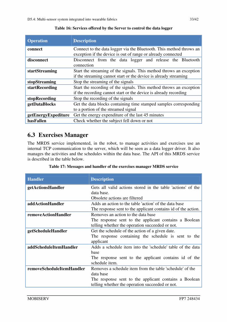
Table 16: Services offered by the Server to control the data logger
Operation Description
connect Connect to the data logger via the Bluetooth. This method throws an
exception if the device is out of range or already connected
disconnect Disconnect from the data logger and release the Bluetooth
connection
startStreaming Start the streaming of the signals. This method throws an exception
if the streaming cannot start or the device is already streaming
stopStreaming Stop the streaming of the signals
startRecording Start the recording of the signals. This method throws an exception
if the recording cannot start or the device is already recording
stopRecording Stop the recording of the signals
getDataBlocks Get the data blocks containing time stamped samples corresponding
to a portion of the streamed signal
getEnergyExpediture Get the energy expenditure of the last 45 minutes
hasFallen Check whether the subject fell down or not
6.3 Exercises Manager The MRDS service implemented, in the robot, to manage activities and exercises use an
internal TCP communication to the server, which will be seen as a data logger driver. It also
manages the activities and the schedules within the data base. The API of this MRDS service
is described in the table below.
Table 17: Messages and handler of the exercises manager MRDS service
Handler Description
getActionsHandler Gets all valid actions stored in the table 'actions' of the
data base.
Obsolete actions are filtered
addActionHandler Adds an action to the table 'action' of the data base
The response sent to the applicant contains id of the action.
removeActionHandler Removes an action to the data base
The response sent to the applicant contains a Boolean
telling whether the operation succeeded or not.
getScheduleHandler Get the schedule of the action of a given date.
The response containing the schedule is sent to the
applicant
addScheduleItemHandler Adds a schedule item into the 'schedule' table of the data
base
The response sent to the applicant contains id of the
schedule item.
removeScheduleItemHandler Removes a schedule item from the table 'schedule' of the
data base
The response sent to the applicant contains a Boolean
telling whether the operation succeeded or not.

D5.4: Multi-sensor system integrated into wearable fabrics 34/42
MOBISERV FP7 248434
Handler Description
actionAckHandler The acknowledgement of the action inform about whether
the user is accepting the action or not.
This method insert the action in the table "report" of the
data base
getReportHandler Gets the report of the actions in a day.
The day is specified by the date in the body of the
message.
The actions done and not done, as scheduled, are included
in the report.
The data of the heart rate, the ECG quality index and the
activity classification are inserted in regular data blocks.
connect Establishes automatically the connection to the device
throw Bluetooth
It polls the device forever and checks the connection. It
will try to connect the device continuously.
setEnergyParametersHandler This message is received when the user wants to configure
the parameters of the fall detection and energy expenditure
sendOperationHandler This message is received when the user wants to start, stop
the streaming or the recording or get the device status
The response sent is contains the device status
sendActivityNotification Send a notification to the application telling it is time for
new action. It contains also the energy expenditure during
the last 45 minutes and telling whether the subject has
fallen or not

D5.4: Multi-sensor system integrated into wearable fabrics 35/42
MOBISERV FP7 248434
7 Electromagnetic compatibility 7.1 Warning This data logger needs special precaution regarding EMC and needs to be installed and put
into service according to the EMC information provided in this chapter. The radiated output
power of this device is well below the FCC radio frequency exposure limits. However, the
antenna used with this transmitter must not be co-located or operated in conjunction with any
other antenna or transmitter to the conditions of the FCC Grant. Bluetooth communication
features:
− Frequency range: 2.40127GHz – 2.48078GHz
− Transmitted power: 5.85dBm EIRP
7.2 Guidance and manufacturer’s declaration – EMC emissions The MOBISERV data logger is intended for use in the electromagnetic environment specified
below. The customer or the user of the Mobiserv data logger should assure that it is used in
such an environment.
Table 18: – Electromagnetic emission –
Emissions test Compliance Electromagnetic environment – guidance
RF emissions
CISPR 11
Group 1 The MOBISERV data logger uses RF energy only
for its internal function. Therefore, its RF emissions
are very low and are not likely to cause any
interference in nearby electronic equipment
RF emissions
CISPR 11
Class B The MOBISERV data logger is suitable for use in
domestic establishments and in establishments
directly connected to a low voltage power supply
network which supplies buildings used for domestic
purposes)
Harmonic emission
IEC 61000-3-2
N/A
Voltage fluctuation/
flicker emissions
IEC 61000-3-3
N/A
7.3 Guidance and manufacturer’s declaration – EMC immunity The MOBISERV data logger is intended for use in the electromagnetic environment specified
below. The customer or the user of the MOBISERV data logger should assure that it is used
in such an environment.

D5.4: Multi-sensor system integrated into wearable fabrics 36/42
MOBISERV FP7 248434
Table 19: – Electromagnetic immunity –
IMMUNITY test IEC 60601
test level
Compliance
level
Electromagnetic environment
– guidance
Electrostatic
discharge (ESD)
IEC 61000-4-2
± 6 kV contact
± 8 kV air
± 6 kV contact
± 8 kV air
Floors should be wood, concrete
or ceramic tile. If floors are
covered with synthetic material,
the relative humidity should be
at least 30 %.
Electrical fast
transient / burst
IEC 61000-4-4
N/A Mains power quality should be
that of a typical commercial or
hospital environment.
Surge
IEC 61000-4-5
N/A Mains power quality should be
that of a typical commercial or
hospital environment
Voltage dips,
short interruption
and voltage
variations on
power supply
lines
IEC61000-4-11
N/A Mains power quality should be
that of a typical commercial or
hospital environment. If the user
of the MOBISERV data logger
requires continued operation
during power mains
interruptions, it is recommended
that the MOBISERV data logger
be powered from an
uninterruptible power supply or
a battery.
Power frequency
(50/60 Hz)
magnetic field
IEC 61000-4-8
3 A/m 3 A/m Power frequency magnetic fields
should be at levels characteristic
of a typical location in a typical
commercial or hospital
environment
Portable and mobile RF communications equipment should be used no closer to any part of
the MOBISERV data logger, including cables, than the recommended separation distance
calculated from the equation applicable to the frequency of the transmitter.
Recommended separation
distance
Conducted RF
IEC 61000-4-5
N/A

D5.4: Multi-sensor system integrated into wearable fabrics 37/42
MOBISERV FP7 248434
IMMUNITY test IEC 60601
test level
Compliance
level
Electromagnetic environment
– guidance
Radiated RF
IEC 61000-4-3
3 V/m
80 MHz to 2.5 GHz
3 V/m From 80MHz and 800MHz
From 800MHz and 2.7MHz
where P is the maximum output
power rating of the transmitter in
watts (W) according to the
transmitter manufacturer and d is
the recommended separation
distance in meters (m).
Field strengths from fixed RF
transmitters, as determined by an
electromagnetic site survey(a)
,
should be less than the
compliance level in each
frequency range.
Interference may occur in the
vicinity of equipment marked
with the following symbol:
NOTE 1: At 80 MHz and 800 MHz, the higher frequency range applies.
NOTE 2: These guidelines may not apply in all situations. Electromagnetic propagation is
affected by absorption and reflection from structures, objects and people
(a) Field strengths from fixed transmitters, such as base stations for radio (cellular/cordless) telephones and
land mobile radios, amateur radio, AM and FM radio broadcast and TV broadcast cannot be predicted
theoretically with accuracy. To assess the electromagnetic environment due to fixed RF transmitters, an
electromagnetic site survey should be considered. If the measured field strength in the location in which
the MOBISERV data logger is used exceeds the applicable RF compliance level above, the
MOBISERV data logger should be observed to verify normal operation. If abnormal performance is
observed, additional measures may be necessary, such as re-orienting or relocating the MOBISERV
data logger.
7.4 Recommended separation distances The MOBISERV data logger is intended for use in an electromagnetic environment in which
radiated RF disturbances are controlled. The customer or the user of the MOBISERV data
logger can help prevent electromagnetic interference by maintaining a minimum distance
between portable and mobile RF communications equipment (transmitters) and the
MOBISERV data logger as recommended below, according to the maximum output power of
the communications equipment

D5.4: Multi-sensor system integrated into wearable fabrics 38/42
MOBISERV FP7 248434
Table 20: Recommended separation distances
Rated maximum output power of transmitter
W
Distance separation according to frequency of transmitter m
80 MHz to 800 MHz
800 MHz to 2,5 GHz
0.01 0.12 0.23
0.10 0.38 0.73
1.00 1.20 2.30
10.0 3.80 7.30
100.00 12.00 23.00
For transmitters rated at a maximum output power not listed above, the recommended
separation distance d in meters (m) can be estimated using the equation applicable to the
frequency of the transmitter, where P is the maximum output power rating of the transmitter in
watts (W) according to the transmitter manufacturer.
NOTE 1: At 80 MHz and 800 MHz, the higher frequency range applies.
NOTE 2: These guidelines may not apply in all situations. Electromagnetic propagation is
affected by absorption and reflection from structures, objects and people.
7.5 Compliant cables and accessories The use of accessories and cables other than those specified or delivery by CSEM as
replacement parts may result in increasing emission or decreasing immunity of the product.
Table 21: List of compliant cables and accessories
Cables and
accessories
Maximum
length Complies with
USB cable 1m CSPR11 ClassB / Group 1 RF electromagnetic disturbance
IEC 61000-4-2 Electrostatic Discharge (ESD)
IEC 61000-4-3 Electromagnetic field radiated by radio-
frequencies
IEC 61000-4-8 Power frequency 50/60Hz magnetic field
Daily Band MOBISERV data logger
Nightly
Pyjamas
MOBISERV data logger
7.6 Essential performances The MOBISERV data logger has neither the sustaining function nor diagnostic of life
supporting function.

D5.4: Multi-sensor system integrated into wearable fabrics 39/42
MOBISERV FP7 248434
8 Getting started For a correct use of the smart garments, the user should follow the instructions listed below:
1. Moisten thoroughly the electrodes with tap water.
Figure 19: Procedure to wet the electrodes
2. Wear the shirt, the band or the pyjama and plug the connector to the MOBISERV Data
Logger.
Figure 20: Plugging the connector on the garments
3. Switch on the MOBISERV data logger by pressing on button A; the led will start blinking
green that means the datalogger is ready with Bluetooth ON (see Table 9).
Figure 21: Switching on the electronic

D5.4: Multi-sensor system integrated into wearable fabrics 40/42
MOBISERV FP7 248434
4. Place the MOBISERV data logger inside the pocket on your:
Band T-shirt Pyjama
Figure 22: Placing the electronic inside the band and T-shirt
5. For the MOBISERV pyjama only: Turn on the MOBISERV ANTTM
module by pressing
the On/Off switch. The led will start blinking.
Figure 23: Turning on the ANT module
6. For the MOBISERV pyjama only: Plug the mini ERNI connector in the MOBISERV
ANTTM
module and place it into the pocket on your chest
Figure 24: Plugging the ERNI connector on the pyjama

D5.4: Multi-sensor system integrated into wearable fabrics 41/42
MOBISERV FP7 248434
9 Maintenance and care 9.1 General guidance for the garment The sensorized garments are realised using natural and synthetic yarns and must be treated as
underwear. Garments have been tested for their endurance regarding number of washings and
time of use. The garment starts to show some malfunctioning after about 50 delicate washing
cycles, probably due to the attack of detergents to metallic fibres; at the same time the fabric
start to wear away.
• Remove all the data loggers from garments before washing them • Washing must be done by hand (no washing machine) in warm water.
• The garment must be washed with a delicate soap (e.g. shampoo) without using softeners.
• Wash separately.
• Do not use bleach.
• Do not tumble dry. • Do not iron.
• Do not pull cables coming out of the vest.
• Do not unplug the connector from the MOBISERV data logger pulling the cables.
9.2 General Guidance for the data logger MOBISERV data logger has to be used with the respect of some basic rules listed below.
− Only perform the procedure described in the user manual.
− Do not disassemble or service your device yourself.
− Protect your device from shocks, hard and sharp objects, extreme heat and prolonged
exposure to direct sunlight.
− Store your device in a clean, dry environment at room temperature.
− Do not place the device where it could be scratched by hard objects.
9.2.1 Cleaning and chemicals
Clean your device with a moist cloth. For stubborn marks, use a mild soap. Do not use
gasoline, cleaning solvents, acetone, alcohol, or insert repellents, paint, or other strong
chemical on your device.
9.3 Disclaimers
9.3.1 User’s responsibility
This device is intended for recreational use only. MOBISERV data logger must not be used
as substitute for obtaining measurements that require professional or laboratory quality
precision.
9.3.2 Warnings
If you have a pacemaker, defibrillator, or other implanted electronic device, you use the MOBISERV data logger transmitter at your own risk. Before using it, we recommend an
exercise test with your MOBISERV data logger. Exercise may include some risk, especially
for those who have been inactive. We strongly advise you to consult your doctor prior to
beginning a regular exercise program.

D5.4: Multi-sensor system integrated into wearable fabrics 42/42
MOBISERV FP7 248434
9.4 Disposal of device
Please dispose of the device in an appropriate way, treating it as electronic
waste. Do not throw it in the garbage.