Embed Size (px)
Citation preview
EU FP7 ICT STREP SEMAFOUR (316384)
INFSO-ICT-316384 SEMAFOUR D2.2
Definition of Requirements for a Unified Self-Management System Contractual Date of Delivery to the EC: June 30th, 2013 Actual Date of Delivery to the EC: July 5th, 2013 Work Package WP2 Participants: NSN-D, ATE, EAB, iMinds, FT, TID, TNO, TUBS, NSN-DK Authors Sana BEN JEMAA, Lars Christoph SCHMELZ, Cinzia SARTORI,
Andreas EISENBLÄTTER, Dario GÖTZ, Dries NAUDTS, Zwi ALTMAN, Beatriz GONZÁLEZ RODRÍGUEZ, Ana María SIERRA DÍAZ, Kostas TRICHIAS, Tanneke OUBOTER, Remco LITJENS, Hans VAN DEN BERG, Thomas KUERNER, Hendrik HOFFMANN, Daniela LASELVA, Istvan KOVACS, Bart SAS, Ljupco JORGUSESKI, Irina BALAN, Yu WANG, Pradeepa RAMACHANDRA
Reviewers Andreas EISENBLÄTTER, Hans VAN DEN BERG, Colin WILLCOCK
Estimated Person Months: 18.5 Dissemination Level Public Nature Report Version 1.0 Total number of pages: 53 Abstract: This document defines the requirements for the unified self-management system that will serve as input to the technical solutions developed in WP5 on the integrated SON management system; and in WP4 on Multi-RAT and multi-layer SON functions. These requirements will also serve as a basis for the validation/verification of the developed technical solutions. Keywords: Self-organization, SON, Multi-RAT, Multi-layer, SON Coordination, Policy Management
SEMAFOUR (316384) D2.2 Definition of requirements for a unified self-management system
Version 1.0 Page 2 of 53
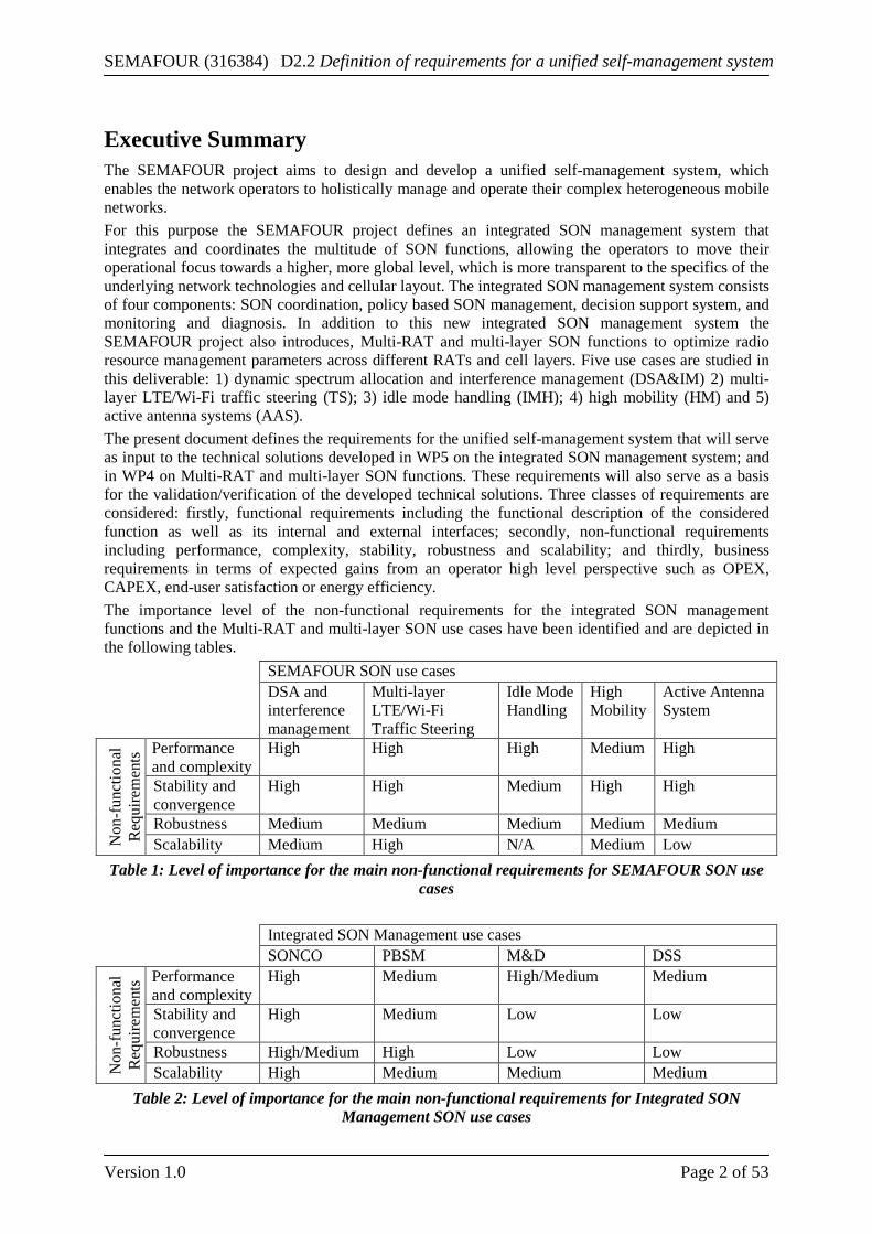
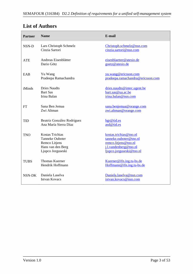
Executive Summary The SEMAFOUR project aims to design and develop a unified self-management system, which enables the network operators to holistically manage and operate their complex heterogeneous mobile networks. For this purpose the SEMAFOUR project defines an integrated SON management system that integrates and coordinates the multitude of SON functions, allowing the operators to move their operational focus towards a higher, more global level, which is more transparent to the specifics of the underlying network technologies and cellular layout. The integrated SON management system consists of four components: SON coordination, policy based SON management, decision support system, and monitoring and diagnosis. In addition to this new integrated SON management system the SEMAFOUR project also introduces, Multi-RAT and multi-layer SON functions to optimize radio resource management parameters across different RATs and cell layers. Five use cases are studied in this deliverable: 1) dynamic spectrum allocation and interference management (DSA&IM) 2) multi-layer LTE/Wi-Fi traffic steering (TS); 3) idle mode handling (IMH); 4) high mobility (HM) and 5) active antenna systems (AAS). The present document defines the requirements for the unified self-management system that will serve as input to the technical solutions developed in WP5 on the integrated SON management system; and in WP4 on Multi-RAT and multi-layer SON functions. These requirements will also serve as a basis for the validation/verification of the developed technical solutions. Three classes of requirements are considered: firstly, functional requirements including the functional description of the considered function as well as its internal and external interfaces; secondly, non-functional requirements including performance, complexity, stability, robustness and scalability; and thirdly, business requirements in terms of expected gains from an operator high level perspective such as OPEX, CAPEX, end-user satisfaction or energy efficiency. The importance level of the non-functional requirements for the integrated SON management functions and the Multi-RAT and multi-layer SON use cases have been identified and are depicted in the following tables. SEMAFOUR SON use cases DSA and
interference management
Multi-layer LTE/Wi-Fi Traffic Steering
Idle Mode Handling
High Mobility
Active Antenna System
Non
-fun
ctio
nal
Req
uire
men
ts Performance
and complexity High High High Medium High
Stability and convergence
High High Medium High High
Robustness Medium Medium Medium Medium Medium Scalability Medium High N/A Medium Low
Table 1: Level of importance for the main non-functional requirements for SEMAFOUR SON use cases
Integrated SON Management use cases SONCO PBSM M&D DSS
Non
-fun
ctio
nal
Req
uire
men
ts Performance
and complexity High Medium High/Medium Medium
Stability and convergence
High Medium Low Low
Robustness High/Medium High Low Low Scalability High Medium Medium Medium
Table 2: Level of importance for the main non-functional requirements for Integrated SON Management SON use cases
SEMAFOUR (316384) D2.2 Definition of requirements for a unified self-management system
Version 1.0 Page 3 of 53
List of Authors
Partner Name E-mail
NSN-D Lars Christoph Schmelz Cinzia Sartori
[email protected] [email protected]
ATE Andreas Eisenblätter Dario Götz
[email protected] [email protected]
EAB Yu Wang Pradeepa Ramachandra
[email protected] [email protected]
iMinds Dries Naudts Bart Sas Irina Balan
[email protected] [email protected] [email protected]
FT Sana Ben Jemaa Zwi Altman
[email protected] [email protected]
TID Beatriz González Rodríguez Ana María Sierra Díaz
[email protected] [email protected]
TNO Kostas Trichias Tanneke Ouboter Remco Litjens Hans van den Berg Ljupco Jorguseski
[email protected] [email protected] [email protected] [email protected] [email protected]
TUBS Thomas Kuerner Hendrik Hoffmann
[email protected] [email protected]
NSN-DK Daniela Laselva Istvan Kovacs
SEMAFOUR (316384) D2.2 Definition of requirements for a unified self-management system
Version 1.0 Page 4 of 53
List of Acronyms and Abbreviations 2G 2nd Generation mobile wireless communication system (GSM, GPRS, EDGE) 3G 3rd Generation mobile wireless communication system (UMTS, HSPA) 3GPP 3rd Generation Partnership Project AAS Active Antenna System ANR Automatic Neighbor Relations AP Access Point AP Absolute Priority CAC Composite Available Capacity CAPEX CAPital Expenditure CCO Coverage and Capacity Optimization CM Configuration Management CQI Quality Class Indicator DSA Dynamic Spectrum Allocation DSS Decision Support System DSS/NE DSS Network Evolution DSS/STM DSS Spectrum and Technology Management ECA Event Condition Action EDGE Enhanced Data rates for GSM Evolution EM Element Manager e-Node B evolved Node B E-UTRAN Evolved UTRAN GERAN GSM EDGE Radio Access Network GPRS General Packet Radio Service GSM Global System for Mobile communication GUI Graphical User Interface HetNet Heterogeneous Networks HO Handover Optimization HSPA High Speed Packet Access HSS Home Subscriber Server ICIC Inter-Cell Interference Coordination IEEE Institute of Electrical and Electronics Engineers IETF Internet Engineering Task Force IM Interference Management IMPEX IMPlementational EXpenditure IRAT Inter-RAT KPI Key Performance Indicator KUI Key User Indicator LAN Local Area Network LTE Long Term Evolution LTE-A Long Term Evolution – Advanced MD Monitoring & Diagnosis MIMO Multiple Input Multiple Output MLB Mobility Load Balancing MNO Mobile Network Operator MRO Mobility Robustness Optimization NE Network Element NGMN Next Generation Mobile Networks OAM Operation, Administration and Maintenance
SEMAFOUR (316384) D2.2 Definition of requirements for a unified self-management system
Version 1.0 Page 5 of 53
OPEX Operational Expenditure PAN Personal Area Network PBSM Policy Based SON Management PCA Principal Component Analysis PM Performance Management QoE Quality of Experience QoS Quality of Service RACH Random Access Channel RAN Radio Access Network RAT Radio Access Technology RRC Radio Resource Control RSRP Reference Signal Received Power RSRQ Reference Signal Received Quality RSS Received Signal Strength RSSI Received Signal Strength Indicator S1 Standardized interface between LTE base station and core network SLA Service Level Agreement SON Self-Organizing Network SONCO SON Coordinator TD-LTE Time Division duplex LTE UMTS Universal Mobile Telecommunications System UTRAN UMTS Terrestrial Radio Access Network VS Vertical Sectorization WLAN Wireless Local Area Network X2 Standardized interface between LTE base stations
SEMAFOUR (316384) D2.2 Definition of requirements for a unified self-management system
Version 1.0 Page 6 of 53
Table of Contents 1 Introduction .................................................................................................. 7
2 Use Cases for Integrated SON Management ............................................. 9 2.1 SON Coordination ...................................................................................................... 9
2.1.1 Definitions and Terminology .......................................................................................... 9 2.1.2 Business Requirements .................................................................................................. 11 2.1.3 Functional Requirements ............................................................................................... 12 2.1.4 Non-Functional Requirements....................................................................................... 14
2.2 Policy Based SON Management .............................................................................. 14 2.2.1 Definitions and Terminology ........................................................................................ 15 2.2.2 Business Requirements .................................................................................................. 16 2.2.3 Functional Requirements ............................................................................................... 16 2.2.4 Non-functional Requirements ....................................................................................... 19
2.3 Decision Support System .......................................................................................... 21 2.3.1 Business requirements ................................................................................................... 21 2.3.2 Functional requirements ................................................................................................ 21 2.3.3 Non-functional requirements ......................................................................................... 25
2.4 Monitoring and Diagnosis ........................................................................................ 26 2.4.1 Definitions and Terminology ........................................................................................ 26 2.4.2 Business Requirements .................................................................................................. 27 2.4.3 Functional Requirements ............................................................................................... 27 2.4.4 Non-Functional Requirements....................................................................................... 30
3 Multi-RAT and Multi-Layer SON Use Cases .......................................... 32 3.1 Dynamic Spectrum Allocation and Interference Management .............................. 32
3.1.1 Business Requirements .................................................................................................. 32 3.1.2 Functional Requirements ............................................................................................... 33 3.1.3 Non-Functional Requirements....................................................................................... 35
3.2 Multi-layer LTE/Wi-Fi Traffic Steering Use Case .................................................. 36 3.2.1 Business Requirements .................................................................................................. 36 3.2.2 Functional Requirements ............................................................................................... 36 3.2.3 Non-Functional Requirements....................................................................................... 38
3.3 Idle Mode Handling Use Case ................................................................................. 39 3.3.1 Business Requirements .................................................................................................. 39 3.3.2 Functional Requirements ............................................................................................... 39 3.3.3 Non-functional requirements ......................................................................................... 41
3.4 High Mobility Use Case ............................................................................................ 41 3.4.1 Business Requirements .................................................................................................. 41 3.4.2 Functional Requirements ............................................................................................... 42 3.4.3 Non-Functional Requirements....................................................................................... 46
3.5 Active Antenna Systems Use Case ........................................................................... 47 3.5.1 Business Requirements .................................................................................................. 47 3.5.2 Functional Requirements ............................................................................................... 48 3.5.3 Non-Functional Requirements....................................................................................... 50
4 Conclusions ................................................................................................. 51
5 References ................................................................................................... 53
SEMAFOUR (316384) D2.2 Definition of requirements for a unified self-management system
Version 1.0 Page 7 of 53
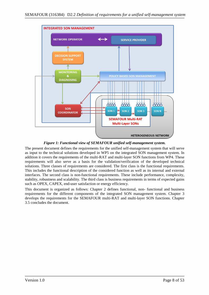
1 Introduction In the context of the ever increasing complexity of today’s mobile networks, with multiple RATs and multiple layers, operators’ long-term competitiveness depends on operational efficiency and agility. The automation of network operation and management was introduced with the standardization of 3GPP Long Term Evolution (LTE), to minimize the operational costs and delays for deploying and running a network by reducing human interventions. Several self-organizing network (SON) functionalities dedicated to self-configuration, self-healing and self-optimization tasks are defined as single-RAT stand-alone features mostly operating independently. The definition of these SON functions is no longer sufficient to guarantee an efficient operation of the increasingly complex heterogeneous networks. To enable efficient operations in the future the whole SON system has to be operated and managed in a unified manner from an operator perspective. SON functions have to operate in a coordinated manner as a part of a global SON system to fulfill together the high level operator objectives. Moreover, in a multi-RAT and multi-layer network, coordinated optimization of radio resource management parameters in different RATs and cell layers is imperative for the global optimization of network performance. The SEMAFOUR projects main objective is to design and develop a unified self-management system, which enables the network operators to holistically manage and operate their complex heterogeneous mobile networks [8]. A global view of the functional architecture of the unified self-management system is shown in Figure 1. The integrated SON management system integrates and coordinates the multitude of SON functions. This allows the operators to move their operational focus to a higher, more global level, which is more transparent to the specifics of the underlying network technologies and cellular layout. For this purpose, four components are specified. Firstly, the SON coordinator (SONCO) in charge of coordinating individual SON functions is specified. This aims to avoid conflicts and undesired behaviors leading to instability in the system. Secondly, we specify the policy based SON management (PBSM). This translates the operator’s high-level network-oriented objectives into dedicated technical rules for individual SON functions. Thirdly we specify the decision support system (DSS). This identifies when and where network upgrades are needed and recommend the most suitable upgrades to the network operator. Lastly the monitoring and diagnosis (MD) component is specified. This provides access to network configuration and performance data to the PBSM, SONCO, and DSS. Multi-RAT and multi-layer SON functions are also developed in SEMAFOUR to jointly optimize radio resource management parameters in different RATs and cell layers. This document includes the requirement specifications for the set of defined in D2.11 “Definition of self-management use cases” [1]. The dynamic spectrum allocation (DSA) and interference management (IM) use case defines algorithms and strategies for an optimized spectrum allocation and interference management in multi-layer and multi-RAT environments. The Multi-layer LTE/Wi-Fi traffic steering (TS) use case, studies QoS based LTE/Wi-Fi traffic steering techniques in dense urban deployments. The idle mode handling (IMH) use case focuses on the optimization of the cell reselection procedure so that the UE always camps on the most appropriate cell. The high mobility (HM) use case optimizes the handover performance of highly mobile users in situations where this poses a noticeable impact on the UE and network performance; and the active antenna systems (AAS) use case studies the AAS feature parameters optimization (e.g. activation / de-activation of vertical sectorization (VS)) both in single RAT and multi-RAT context to increase the network capacity.
1 Note that he multi-flow use case introduced in D2.1 will not be developed in this deliverable. At the time of writing of this deliverable the 3GPP Release 12 small cell enhancement studies regarding dual connectivity has not yet matured. Hence studying this use case in SEMAFOUR is still an open issue.
SEMAFOUR (316384) D2.2 Definition of requirements for a unified self-management system
Version 1.0 Page 8 of 53
Figure 1: Functional view of SEMAFOUR unified self-management system.
The present document defines the requirements for the unified self-management system that will serve as input to the technical solutions developed in WP5 on the integrated SON management system. In addition it covers the requirements of the multi-RAT and multi-layer SON functions from WP4. These requirements will also serve as a basis for the validation/verification of the developed technical solutions. Three classes of requirements are considered. The first class is the functional requirements. This includes the functional description of the considered function as well as its internal and external interfaces. The second class is non-functional requirements. These include performance, complexity, stability, robustness and scalability. The third class is business requirements in terms of expected gains such as OPEX, CAPEX, end-user satisfaction or energy efficiency. This document is organized as follows: Chapter 2 defines functional, non- functional and business requirements for the different components of the integrated SON management system. Chapter 3 develops the requirements for the SEMAFOUR multi-RAT and multi-layer SON functions. Chapter 3.5 concludes the document.
SEMAFOUR (316384) D2.2 Definition of requirements for a unified self-management system
Version 1.0 Page 9 of 53
2 Use Cases for Integrated SON Management This chapter specifies the business, functional and non-functional requirements for the four functions of the integrated SON management system.
• The SON coordination function (SONCO) coordinates individual SON functions to avoid conflicts and undesired behaviors leading to instability in the system;
• The Policy based SON management (PBSM) translates the operator’s high-level network-oriented objectives into dedicated technical rules for individual SON functions;
• The decision support system (DSS) identifies when and where network upgrades are needed and recommend the most suitable upgrades to the network operator;
• The monitoring and diagnosis function (MD) provides access to network configuration and performance data to the PBSM, SONCO, and DSS.
The chapter is structured as follows: in Section 2.1 operational SON coordination is explained. Section 2.2 introduces policy-based SON management, section 2.4 monitoring and diagnosis, and section 2.3 the decision support system. The general structure for all sections is such that first, the major tasks and definitions of the functional blocks of integrated SON management are introduced. Second, the business requirements are explained, third, the functional requirements, and finally the non-functional requirements.
2.1 SON Coordination The tasks of the SON Coordinator (SONCO) are:
• Conflict detection: SONCO shall detect conflicts between simultaneously running SON functions;
• Conflict resolution/prevention at run-time: The SONCO shall decide on how a conflict is to be avoided prior to enforcing the corresponding conflicting actions into the network;
• Undo: The SONCO can undo action(s) it recently enforced; • Priority handling: The SONCO acts in line with the priorities assigned to SON functions by
the PBSM; • Feedback to the PBSM in order to improve the PBSM SON policies’ definition, taking into
account SONCO detected conflict aspects. For instance, a conflict occurring frequently may be due to a bad policy design.
The remainder of this section is organized as follows. First, some definitions related to the temporal and spatial scope of SON functions, and conflict definitions are given. Then, business, functional and non-functional requirements are developed for the SONCO.
2.1.1 Definitions and Terminology The following definitions are given as a starting point for the discussions in WP5 and for developing a common understanding of the SONCO function. They will likely evolve during the project.
Spatial SON Function Scope (see also [7]) Each SON function instance binds to a target, which can be a single cell, a set of cells, an NE or a set of NEs. The changes performed by this function instance directly affect the configuration of the target. The target therefore forms the function area of the SON function instance. Furthermore, there may be additional cells or NEs that are important for the SON function instance. This is, for example, the case if measurements are taken from these cells or NEs; or if these cells or NEs are indirectly affected by the changes to the target; or changes to these cells or NEs from outside the SON function instance will impact the SON function in a way that erroneous results may be computed. These additional cells and NEs are denominated as the influence area of a SON function instance.
SEMAFOUR (316384) D2.2 Definition of requirements for a unified self-management system
Version 1.0 Page 10 of 53
Both, the function area together with the influence area of a SON function instance form the impact area of a SON function instance. For the purpose of SON coordination the function area and the complete impact area have to be considered.
Temporal SON Function Scope (see also [7]) A SON function instance has to be considered by the SONCO during the complete time period it may impact the network or other relevant SON function instances. This time period is denominated as impact time. Outside the impact time a SON function instance is considered not to have any effects on other SON function instances. This means that SON coordination becomes relevant in case there are overlapping impact times between two different SON function instances. The impact time of a SON function instance is composed of a set of different components reflecting the different tasks while being active. The length of each of the different impact time components depends on the particular SON function and on the context of the dedicated SON function instance (for example, if the instance is running on a micro or a macro cell). Some of the components may even be zero, for instance, in case a configuration parameter change becomes instantly visible in the network. The impact time components are:
• Measurement interval: The time during which a SON function instance collects measurements, or monitors measurements and KPIs in order to detect a trigger situation, or to use the collected measurements as input to the SON algorithm.
• Execution time: The time during which the actual SON algorithm is running in order to compute new configuration parameter values.
• Enforcement interval: The time during which the newly computed configuration parameter values are deployed to the network (cell, NE). This may take some time, depending on the mechanisms used to deploy the values. The enforcement time finishes when the acknowledgement for the changes arrives at the mechanism used to deploy the changes.
• Visibility delay: The time required until changes performed by the SON function instance become fully visible in the corresponding measurements. Considering standard performance management mechanisms (measurements granularity period, see also [7]), there may be a considerable delay until a complete granularity period of measurements reflects the configuration parameter changes.
• Relevance interval: The time during which changes performed by one SON function instance are relevant for other SON function instances, for example, in order to prevent from changes performed by one SON function being revoked by other SON functions, or to prevent from oscillating configuration changes through alternately enforcing SON functions. The relevance interval may thereby be rather long depending on the requirements regarding the prevention of oscillations.
Note that the definition of the impact time of a SON function is directional, for example, from SON function A towards SON function B. An interaction from A to B does not automatically imply an interaction from B to A. Therefore, the definition of the impact time is to be done pair wise between SON functions.
Conflict Definition The following table describes different conflict categories. Cat. Conflict Description Example I Configuration conflict: A conflict induced by changes to a configuration parameter. I.a Input
parameter conflict
SON functions that deal with parameters whose values are dependent on the values of other parameters can suffer from an input parameter conflict, as they rely on the stability of the values of read parameters to compute the new configuration settings. In case the values of these read parameters change during computation the new
A PCI function instance gathers the PCIs of neighbor cells in order to allocate a PCI for the target cell. If a neighbor PCI is changed during the runtime of the PCI function instance the resulting configuration for the
SEMAFOUR (316384) D2.2 Definition of requirements for a unified self-management system
Version 1.0 Page 11 of 53
configuration settings may be wrong. target cell can be erroneous. I.b Output
parameter conflict
When a SON function instance tries to modify a configuration parameter within the impact time of another function instance (i.e., that configuration has been/is manipulated by that other function instance), an output parameter conflict occurs.
Two SON function may compete over their shared parameters, where one instance requests a parameter increase while the second instance requests to decrease this parameter after a short time interval. This may lead to undesired oscillation effects.
II Measurement conflict: A conflict induced by the change to a measurement II.a Measure-
ment conflict
Measurements may on the one hand trigger SON function algorithm execution, and on the other hand serve as input to the SON function algorithm to evaluate the current state of the system and deduce appropriate configurations / actions to reach the intended target. Parameter changes made to the system hence influence the measurements, but it takes some time until these changes show effect in the measurements. This delay may lead to conflicts in case a SON function is either triggered or computes new parameter values based on actually “outdated” measurements.
An MRO function instance collecting measurements over a longer time may be influenced by a simultaneously running MLB instance, which modifications influence the measurements (e.g., call drop ratio) taken by MRO.
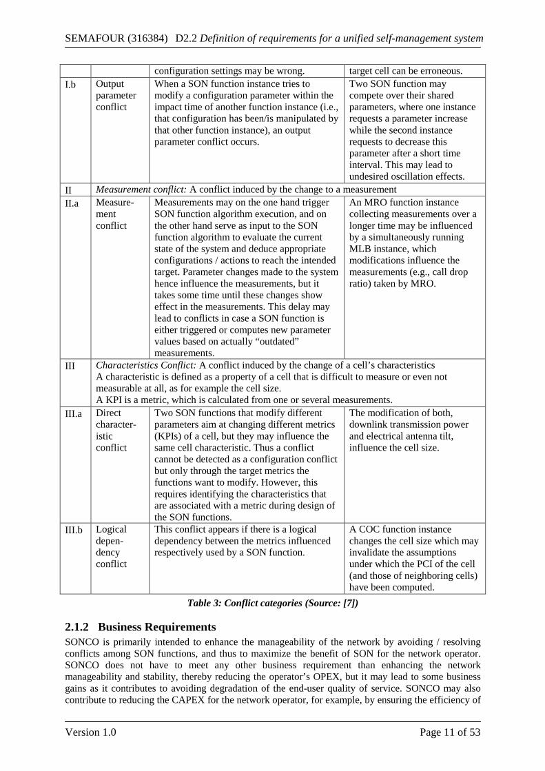
III Characteristics Conflict: A conflict induced by the change of a cell’s characteristics A characteristic is defined as a property of a cell that is difficult to measure or even not measurable at all, as for example the cell size. A KPI is a metric, which is calculated from one or several measurements.
III.a Direct character-istic conflict
Two SON functions that modify different parameters aim at changing different metrics (KPIs) of a cell, but they may influence the same cell characteristic. Thus a conflict cannot be detected as a configuration conflict but only through the target metrics the functions want to modify. However, this requires identifying the characteristics that are associated with a metric during design of the SON functions.
The modification of both, downlink transmission power and electrical antenna tilt, influence the cell size.
III.b Logical depen-dency conflict
This conflict appears if there is a logical dependency between the metrics influenced respectively used by a SON function.
A COC function instance changes the cell size which may invalidate the assumptions under which the PCI of the cell (and those of neighboring cells) have been computed.
Table 3: Conflict categories (Source: [7])
2.1.2 Business Requirements SONCO is primarily intended to enhance the manageability of the network by avoiding / resolving conflicts among SON functions, and thus to maximize the benefit of SON for the network operator. SONCO does not have to meet any other business requirement than enhancing the network manageability and stability, thereby reducing the operator’s OPEX, but it may lead to some business gains as it contributes to avoiding degradation of the end-user quality of service. SONCO may also contribute to reducing the CAPEX for the network operator, for example, by ensuring the efficiency of
SEMAFOUR (316384) D2.2 Definition of requirements for a unified self-management system
Version 1.0 Page 12 of 53
the SON system and hence the network itself, enabling the deferral of network hardware enhancements Without coordination, conflicting SON functions might induce sub-optimal performance of the network that leads to the degradation of end-user perceived quality of service. For example, oscillations of handover parameters due to uncoordinated actions from SON functions that impact these parameters (e.g. MRO, MLB) result in increasing the number of unnecessary handovers in the network. This increases both the signaling overhead and the probability of call drop due to HO failure.
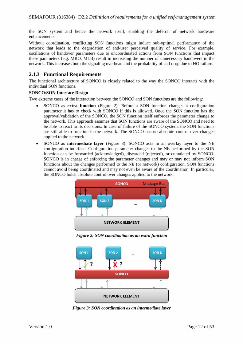
2.1.3 Functional Requirements The functional architecture of SONCO is closely related to the way the SONCO interacts with the individual SON functions. SONCO/SON Interface Design Two extreme cases of the interaction between the SONCO and SON functions are the following:
• SONCO as extra function (Figure 2): Before a SON function changes a configuration parameter it has to check with SONCO if this is allowed. Once the SON function has the approval/validation of the SONCO, the SON function itself enforces the parameter change to the network. This approach assumes that SON functions are aware of the SONCO and need to be able to react to its decisions. In case of failure of the SONCO system, the SON functions are still able to function in the network. The SONCO has no absolute control over changes applied to the network.
• SONCO as intermediate layer (Figure 3): SONCO acts in an overlay layer to the NE configuration interface. Configuration parameter changes to the NE performed by the SON function can be forwarded (acknowledged), discarded (rejected), or cumulated by SONCO. SONCO is in charge of enforcing the parameter changes and may or may not inform SON functions about the changes performed to the NE (or network) configuration. SON functions cannot avoid being coordinated and may not even be aware of the coordination. In particular, the SONCO holds absolute control over changes applied to the network.
Figure 2: SON coordination as an extra function
Figure 3: SON coordination as an intermediate layer
SEMAFOUR (316384) D2.2 Definition of requirements for a unified self-management system
Version 1.0 Page 13 of 53
While the first approach takes benefit from an explicit interface for the communication between the SONCO and the SON functions, the second approach can simply replicate the control interface of network elements (managers). The choice of the design has a major impact on the role and responsibilities of the SONCO within the integrated SON management system. The actual implementation is likely to be a hybrid version blending aspects of both extremes; the SONCO will have an explicit interface for SON functions. This interface will allow for exchanging information between the SONCO and the SON functions. However, within the SEMAFOUR project simulations may be run for both approaches in order to get a more detailed view on advantages and disadvantages, for example, regarding robustness, flexibility, or the applicability to a layered or distributed implementation.
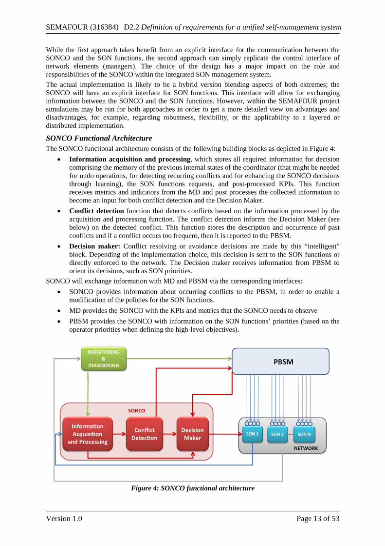
SONCO Functional Architecture The SONCO functional architecture consists of the following building blocks as depicted in Figure 4:
• Information acquisition and processing, which stores all required information for decision comprising the memory of the previous internal states of the coordinator (that might be needed for undo operations, for detecting recurring conflicts and for enhancing the SONCO decisions through learning), the SON functions requests, and post-processed KPIs. This function receives metrics and indicators from the MD and post processes the collected information to become an input for both conflict detection and the Decision Maker.
• Conflict detection function that detects conflicts based on the information processed by the acquisition and processing function. The conflict detection informs the Decision Maker (see below) on the detected conflict. This function stores the description and occurrence of past conflicts and if a conflict occurs too frequent, then it is reported to the PBSM.
• Decision maker: Conflict resolving or avoidance decisions are made by this “intelligent” block. Depending of the implementation choice, this decision is sent to the SON functions or directly enforced to the network. The Decision maker receives information from PBSM to orient its decisions, such as SON priorities.
SONCO will exchange information with MD and PBSM via the corresponding interfaces: • SONCO provides information about occurring conflicts to the PBSM, in order to enable a
modification of the policies for the SON functions. • MD provides the SONCO with the KPIs and metrics that the SONCO needs to observe • PBSM provides the SONCO with information on the SON functions’ priorities (based on the
operator priorities when defining the high-level objectives).
Figure 4: SONCO functional architecture
SEMAFOUR (316384) D2.2 Definition of requirements for a unified self-management system
Version 1.0 Page 14 of 53
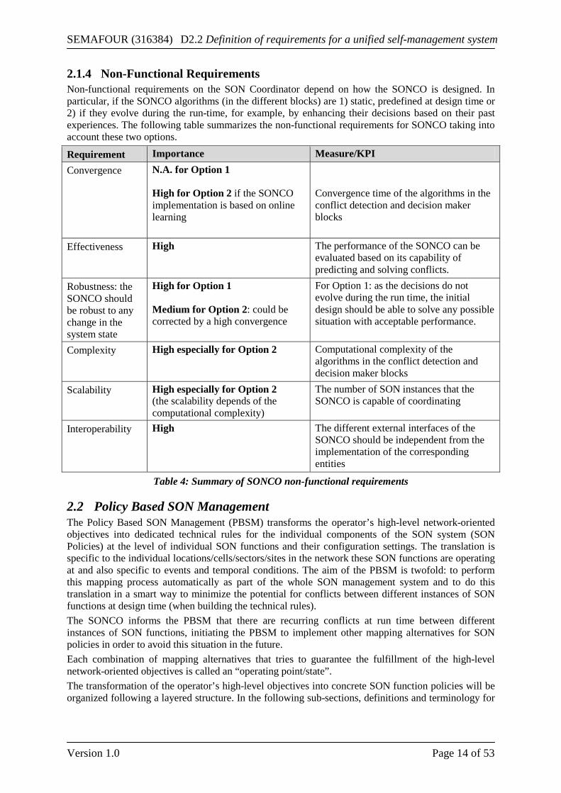
2.1.4 Non-Functional Requirements Non-functional requirements on the SON Coordinator depend on how the SONCO is designed. In particular, if the SONCO algorithms (in the different blocks) are 1) static, predefined at design time or 2) if they evolve during the run-time, for example, by enhancing their decisions based on their past experiences. The following table summarizes the non-functional requirements for SONCO taking into account these two options.
Requirement Importance Measure/KPI Convergence N.A. for Option 1
High for Option 2 if the SONCO implementation is based on online learning
Convergence time of the algorithms in the conflict detection and decision maker blocks
Effectiveness High The performance of the SONCO can be evaluated based on its capability of predicting and solving conflicts.
Robustness: the SONCO should be robust to any change in the system state
High for Option 1 Medium for Option 2: could be corrected by a high convergence
For Option 1: as the decisions do not evolve during the run time, the initial design should be able to solve any possible situation with acceptable performance.
Complexity High especially for Option 2 Computational complexity of the algorithms in the conflict detection and decision maker blocks
Scalability High especially for Option 2 (the scalability depends of the computational complexity)
The number of SON instances that the SONCO is capable of coordinating
Interoperability High The different external interfaces of the SONCO should be independent from the implementation of the corresponding entities
Table 4: Summary of SONCO non-functional requirements
2.2 Policy Based SON Management The Policy Based SON Management (PBSM) transforms the operator’s high-level network-oriented objectives into dedicated technical rules for the individual components of the SON system (SON Policies) at the level of individual SON functions and their configuration settings. The translation is specific to the individual locations/cells/sectors/sites in the network these SON functions are operating at and also specific to events and temporal conditions. The aim of the PBSM is twofold: to perform this mapping process automatically as part of the whole SON management system and to do this translation in a smart way to minimize the potential for conflicts between different instances of SON functions at design time (when building the technical rules). The SONCO informs the PBSM that there are recurring conflicts at run time between different instances of SON functions, initiating the PBSM to implement other mapping alternatives for SON policies in order to avoid this situation in the future. Each combination of mapping alternatives that tries to guarantee the fulfillment of the high-level network-oriented objectives is called an “operating point/state”. The transformation of the operator’s high-level objectives into concrete SON function policies will be organized following a layered structure. In the following sub-sections, definitions and terminology for
SEMAFOUR (316384) D2.2 Definition of requirements for a unified self-management system
Version 1.0 Page 15 of 53
this layered transformation procedure are described. Moreover, the business requirements, the functional requirements as well as the non-functional requirements for the PBSM are specified.
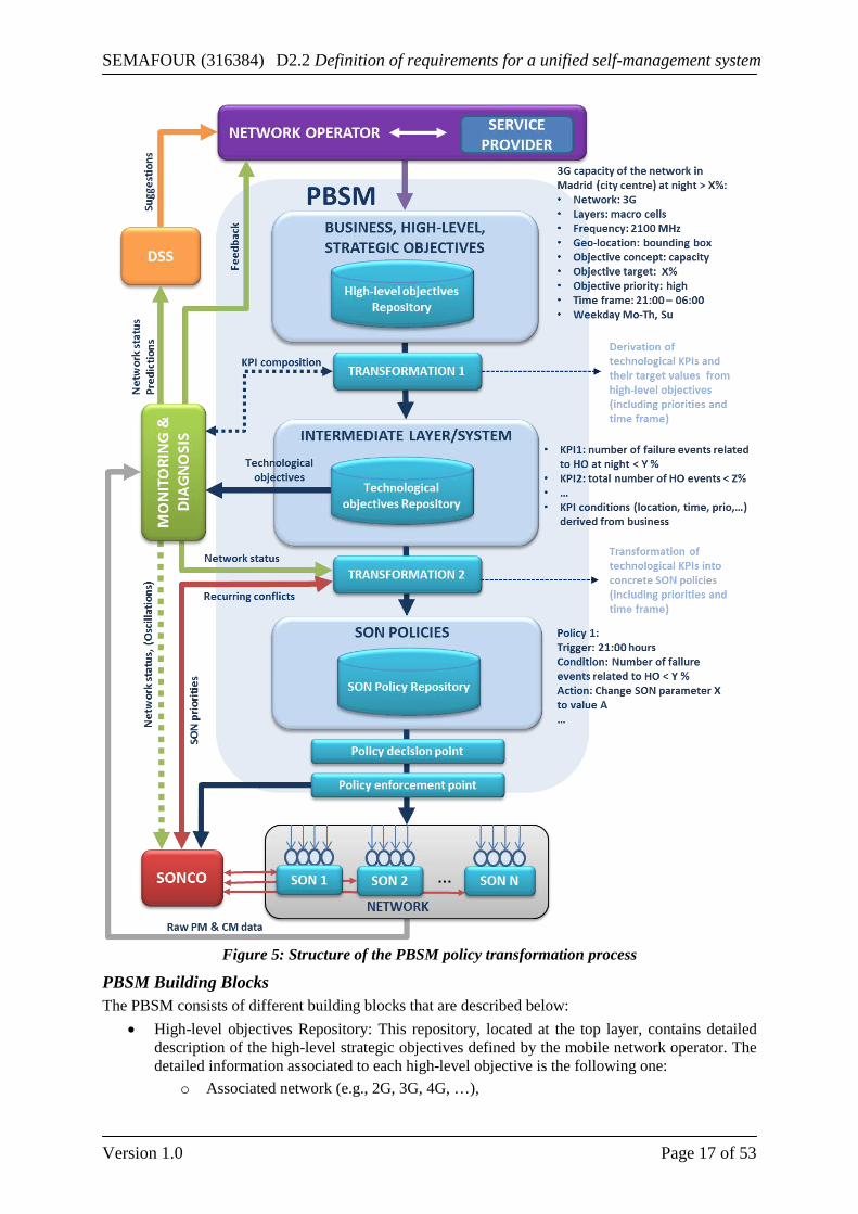
2.2.1 Definitions and Terminology The transformation of the operator’s high-level network-oriented objectives into policies and rules for the individual SON functions can be performed with several intermediate steps. Transforming a given operator objective into SON policies comprises relating the given objective to the network configuration and performance, identifying relevant SON functions, and deciding on how to instrument them for the intended purposes. According to these steps, the transformation process can be subdivided into three logical layers (see also Figure 5). A short definition of these three layers and the transformation processes between these layers are provided in the following.
Layered Structure Mapping a given operator objective into SON policies comprises relating the given objective to the network configuration and performance, identifying relevant SON functions, and deciding on how to instrument them for the intended purposes. Three distinct logical layers are foreseen to provide contexts for each of the necessary steps (see Figure 5).
• The top layer (high-level objectives) contains high-level business, strategic and technical objectives.
• The intermediate layer (system layer) provides a detailed network description based on which the network performance can be assessed. This description should be at the level of cells and cell relations. The intermediate layer is unaware of SON functions.
• The bottom layer (SON policies) contains policies for controlling SON functions acting in the network.
These layers are intended to be clearly separated such that each of them may stand for itself. This assumption allows for splitting the whole transformation process into smaller pieces that can be investigated independently within their respective contexts. We furthermore suggest designing the layers each to be complete (i.e., after the transformation process has completed, the layer contains all relevant data necessary to express the operator’s goals at that layer), self-contained (i.e., the operator’s goals can be interpreted within the context of that layer without relying on other layers), and independent (with respect to their syntax and semantics) in order to achieve this separation.
Transformation (Inter-layer Mapping) Communication between layers necessitates mappings between the corresponding syntax and semantics. High-level objectives passed down to the intermediate layer need to be transformed before having a meaning within the context of the intermediate layer. Another mapping is needed when SON policies are constructed from technological objectives at the intermediate layer. That is, transformation processes play a distinguished role in this setup. Obviously, knowledge about the syntax / semantics of the source and target layers is necessary when mapping from one layer to another. Mapping and feedback are mostly seen as happening between layers. If the transformation processes between two layers were part of either of the layers, then logical separation between the layers would become blurred. In particular, the layers would not be independent anymore. Considering, for example, the transformation from the top to the intermediate layer as a part of the latter, then the addition of a new category of high-level objectives would entail changes to the intermediate layer. Whereas, if we consider the transformation as something between layers, then the transformation process needs update, but not the intermediate layer.
Objectives and Policies Within SEMAFOUR, an objective defines target values / ranges for parameters or for high-level “concepts” (such as, for example, capacity, coverage, and interference). An objective does (in general) not include instructions on how to reach these targets. All objectives taken together shall describe the desired network behavior (either by stating what is desired or what is to be avoided). Each individual objective contributes to this overall goal. When a network state is checked against all objectives, then a pointed list of discrepancies between what is desired and what is observed can be derived. These
SEMAFOUR (316384) D2.2 Definition of requirements for a unified self-management system
Version 1.0 Page 16 of 53
discrepancies can then be used (at SON policy level) to trigger changes to the network by means of SON functions/instances execution. Ideally, the objectives even lay out which changes are preferred over others (but they do not define what to do), based on the preferences provided by the operator at the top layer. The concept of objectives should be employed at the top and middle layers. It may prove to be necessary to include events/condition dependences into the objective concept. Within SEMAFOUR, a policy is defined as an Event – Condition – Action (ECA) policy, consisting of an event on which the execution of the policy is triggered, at least one condition, and an action that is taken if the condition is met. The action part of a policy states instructions. Notice that a policy does not need to explicitly state its purpose or goal. Each individual policy details what is to be done under specific conditions (on the triggering event). An individual policy thus needs to be in line with the objectives, but whether or not this is the case cannot generally be determined from considering a policy in isolation. Instead, the collection of all policies as a whole implicitly defines objectives. Hence, the objectives are concealed and testing if a network state is desired amounts to checking all applicable policies. But even if some policies still trigger actions, the state may be desirable already (compare this to power up / down command in the closed loop power control of UMTS – there is no “leave it as it is”). The policy concept appears favorable for the bottom layer since here it needs to be determined how SON functions can be employed in the network in order to implement the desired objectives.
2.2.2 Business Requirements Several business requirements have been identified:
• OPEX reduction: As it was mentioned previously for the SONCO, it is expected also for the PBSM to have a high impact on this metric, based on the whole automation of the translation process from high-level objectives down to SON policies and their execution, when comparing to a manual approach. Taking into account the inherent intelligence inside the PBSM transformation processes and the feedback loops coming from the SONCO and the MD, the adaptation of these processes to new changes coming both from the network and from the mobile network operator strategic objectives will be executed faster and with a wider perspective than manually done.
• End-user satisfaction: For the PBSM there are two types of end-users: o The first type of end-users would be comprised of the different marketing and
technical departments of the mobile network operator involved in the high-level objectives design, implementation, and execution into the network itself. PBSM would be seen by them as a single entity for the whole process, opposite to the current situation where the departments are typically coordinated by means of periodical face-to-face meetings, just for checking the whole process and the results, or for notifying the other departments about any change done in the objectives and/or the way of execute them.
o The second type of end-users would be the clients / users of the mobile networks. Considering the PBSM’s intelligent transformation processes, the PBSM will perform an improvement in the quality perceived by the user. Taking into account the feedback information coming from the SONCO and the MD, that will help the PBSM to react quickly against sub-optimal performance and act accordingly to that, a better translation and execution of SON policies that will improve the current mobile network status (in terms of performance) will be provided..
A direct CAPEX reduction by the implementation PBSM is not expected. However, there may be indirect CAPEX reductions, for example, due to the PBSM contribution to a more efficient utilization of the already deployed network infrastructure.
2.2.3 Functional Requirements Based on the structural layered design detailed in the previous section the PBSM functional architecture block diagram is depicted in Figure 5.
SEMAFOUR (316384) D2.2 Definition of requirements for a unified self-management system
Version 1.0 Page 17 of 53
Figure 5: Structure of the PBSM policy transformation process
PBSM Building Blocks The PBSM consists of different building blocks that are described below:
• High-level objectives Repository: This repository, located at the top layer, contains detailed description of the high-level strategic objectives defined by the mobile network operator. The detailed information associated to each high-level objective is the following one:
o Associated network (e.g., 2G, 3G, 4G, …),
SEMAFOUR (316384) D2.2 Definition of requirements for a unified self-management system
Version 1.0 Page 18 of 53
o Associated layer (e.g., macro only, micro only, all, …), o Frequency band, o High-level objective impact area: List of network elements installed in the
geographical area linked to the high-level objective. This list is defined by the mobile network operator through the GUI typically as a bounding box,
o High-level objective concept: Network category that best suits the high-level objective (e.g. coverage, capacity, interference, mobility robustness, drop calls’ rate, …),
o High-level objective target value: Target threshold associated to the high-level objective concept,
o High-level objective priority: The mobile network operator can associate different priorities to the high-level objectives by means of this indicator,
o Conditions (e.g., time frame, weather status,…) during which the high-level objective should be fulfilled,
o Others for further refinement. • First Transformation Process: It derives the technological objectives (associated to one or
several specific KPIs) and their target values (including priorities and time frame) from the high-level objectives. The transformation process takes a model of the SON system including the current network configuration into account and identifies suitable KPIs to be monitored and evaluated by the MD. These KPIs are chosen to reflect the high-level objectives as closely as possible.
• Technological Objectives Repository: This repository, located at the intermediate layer, stores a detailed description of the technological objectives associated to the high-level objectives coming from the top layer.
• Second Transformation Process: It derives the SON policies (including priorities and associated time frame) from the technological objectives. As stated in Section 2.2.1, the SON policies follow the structure of the ECA policies, which are policies consisting of an event on which it is triggered, a condition, and an action that is taken when the condition is met. For the SON policies at the PBSM the events and the conditions are derived from the technological KPIs and their associated target values respectively, whereas the actions are the appropriate SON instances with their associated configuration settings (SON 1, SON 2, …). Further input to the second transformation process is a model of the SON functions available in the network.
• SON Policy Repository: This repository, located at the bottom layer, stores the SON policies that will later be enforced on the network by the policy enforcement module.
• Policy Decision: This entity listens for trigger events and, once such an event occurs, activates the corresponding SON policies within the SON policy repository.
• Policy Enforcement: The Policy enforcement block is responsible for updating configuration settings of SON functions that will act on the network according to activated SON policies within the SON policy repository.
PBSM External Interfaces The PBSM interfaces with the following entities:
• Interface with the network operator GUI: The mobile network operator is responsible for providing the system with the high-level objectives. In order to simplify the creation of high-level objectives, a straightforward language should be specified such that detailed information can be implemented easily.
• Interfaces with the MD module: o The PBSM provides the MD with information regarding the technological objectives.
This information is a requirement for the MD module in order to detect whether the current network operating point/state satisfies the technological objectives.
o The PBSM and the MD exchange information regarding KPI composition in order to best possibly reflect the requirements of the high-level objectives. The introduction of
SEMAFOUR (316384) D2.2 Definition of requirements for a unified self-management system
Version 1.0 Page 19 of 53
new high-level objectives may initiate the monitoring of new KPIs. In the other direction, the PBSM uses the information from the MD about available and possible KPIs for the derivation of technological objectives.
o The MD provides the PBSM with information regarding the network operating point/state and target values that will help the second transformation process to derive SON policies from technological objectives.
• Interface with the SONCO module: The PBSM and the SONCO exchange information regarding recurring conflicts (from the SONCO to the PBSM) and the identified SON priorities (from the PBSM to the SONCO). The PBSM uses the incoming information regarding recurring conflicts to implement a different strategy when building the SON policies. The PBSM sends the SON priorities to the decision maker module inside the SONCO to assist it in the conflict solving or avoidance decision process.
• Interface with the SON functions: The PBSM sends appropriate configuration settings and the associated priority to each available/active SON function through the policy enforcement point.
PBSM Main Functional Requirements The main functional requirements of the PBSM are summarized in the following list:
• Transformation of objectives from the high-level objective layer to the intermediate layer; • Transformation of objectives from the intermediate layer to policies in the SON layer; • Minimization of conflicts between different SON instances at design-time (when building the
technical rules); • Adaptation of previous mapping from high-level network-oriented objectives to specific SON
policies when the MD module informs the PBSM that the high-level network-oriented objectives are not being satisfied;
• Adaptation of previous mapping from high-level network-oriented objectives to specific SON policies in case the current mapping is causing a conflict between different SON instances at run-time;
• Storage of information about the input-output relations of SON functions in order to make the best decision at the PBSM on the SON configuration settings to improve the network performance and avoid conflicts between SON functions.
2.2.4 Non-functional Requirements Several non-functional requirements have been identified:
Requirement Importance Measure/KPI Convergence Medium: It is necessary to minimize the
convergence time that the PBSM requires for the transformation of new or changed high-level objectives into SON policies. This requirement includes also the refinement process for improving the SON policies when the PBSM is informed about recurring conflicts by the SONCO.
Time elapsed between the introduction/change of a high-level objective and the production of corresponding SON policies.
Scalability Medium: Depending on the number and structure of the given high-level objectives, the PBSM needs to maintain a large set of technological objectives and SON policies with varying level of detail. The PBSM must be scalable with respect to these quantities and regarding the addition of new SON functions.
Number of objectives, policies and SON functions maintainable by the PBSM.
Completeness High: The information available at each layer within the PBSM should ideally give a complete picture of
Mapping table with correspondences between high-level objectives,
SEMAFOUR (316384) D2.2 Definition of requirements for a unified self-management system
Version 1.0 Page 20 of 53
the operator goals. It is therefore necessary to transform each high-level objective into one or several technological KPIs, and in turn each technological KPI must be transformed into one or several SON policies (neither high-level objectives nor technological KPIs must be kept without this mapping)
technological KPIs and SON policies.
Effectiveness High: The SON policies produced by the PBSM should optimally reflect the high-level goals of the network operator. The effectiveness of the transformation processes is ideally reflected by discrepancy of the current and the desired network performance. Since measurements for network performance are accessible at intermediate layer, this assessment is best carried out in terms of technological KPIs.
Difference between current and target values of maintained technological KPIs.
Performance and Complexity
Medium: The PBSM needs to be a reliable source of information for MD and SONCO regarding KPI composition and SON priorities. The performance of the interface to the SONCO is of particular importance, since run-time conflicts need to be resolved at a very small time scale. The complexity of the PBSM is mainly associated to computational complexity for the transformation processes and the amount of objectives and policies to be stored in the repositories.
Response time for providing information to MD and SONCO. Computation time for the transformation process. Required storage capacity for objectives and policies.
Robustness High: The PBSM should be robust to any change and/or inconsistency coming from the high-level objectives. When a new high-level objective is defined by the mobile network operator the PBSM must adapt the existing SON policies to the new requirements by means of probably new SON priorities and new SON functions’ configuration settings. Even when a new SON function is provided by the vendor and the mobile network operator includes it into the set of active SON functions, the PBSM must manage this new SON function and incorporate it into the SON policies. Also detecting inconsistencies during the transformation process to define the SON policies and correcting them is a requirement for the PBSM, just to avoid the inconsistencies being implemented into the network by the SON functions.
Robustness is closely related to completeness, effectiveness and scalability, therefore the same measure/KPI could be used for it. A new KPI is the number of inconsistencies during the transformation processes (an example of inconsistency could be acting on the same KPI with associated increasing and decreasing targets on the same cell at the same conditions).
Interoperability High: This is a very important requirement for the PBSM as one of the main aims of the layered structure proposed in WP5 is to guarantee the interoperability between independent layers and processes. This means that the internal (within the PBSM) and external (between PBSM and other entities) interfaces are independently implemented, simplifying a hypothetical multi-vendor environment.
N/A
Table 5: Summary of PBSM non-functional requirements
SEMAFOUR (316384) D2.2 Definition of requirements for a unified self-management system
Version 1.0 Page 21 of 53
2.3 Decision Support System In this section the Decision Support System (DSS) requirements are investigated for the specific use cases ‘Spectrum and technology management’ (DSS/STM) and ‘Network evolution’ (DSS/NE). The basic principle for both DSS use cases is the same: identify when and where network upgrades are needed and recommend the most suitable upgrades to the network operator. Key distinction between the two use cases lies in the nature of the network upgrades: in the DSS/STM use case the considered network upgrades entail the migration of existing sites to support new radio access technologies, technological features or the installation of new hardware to support new frequency bands2; considered network upgrades in the DSS/NE use case are primarily new site deployments. In the description below, these distinctions are not relevant and hence both use cases are considered as one. For these combined use cases, the DSS basically comprises two key tasks, or stages. First DSS stage is to identify when and for which area recommendations for network upgrades are to be derived, while the second DSS stage assesses a list of potential network upgrades, derives a shortlist of most suitable candidates and reports this to the network operator, along with a prediction of the performance impact over time.
2.3.1 Business requirements The most important business requirements for the DSS concern OPEX reduction, CAPEX reduction, and user satisfaction.
• OPEX reduction: Obviously, as one of its main objectives, the DSS should reduce the need for human involvement in triggering and determining network upgrades by largely automating these processes
• CAPEX reduction: The DSS shall search for network upgrades that require minimum investments for network equipment, etc., while keeping the KPIs at the required level (see below)
• User satisfaction: The DSS shall help to maintain (at the longer term) the KPI’s at the required level and meet the SLAs agreed upon with the users
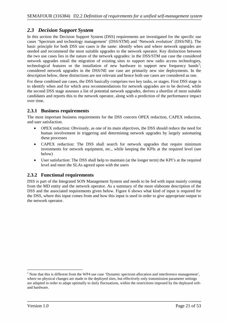
2.3.2 Functional requirements DSS is part of the Integrated SON Management System and needs to be fed with input mainly coming from the MD entity and the network operator. As a summary of the more elaborate description of the DSS and the associated requirements given below. Figure 6 shows what kind of input is required for the DSS, where this input comes from and how this input is used in order to give appropriate output to the network operator.
2 Note that this is different from the WP4 use case ‘Dynamic spectrum allocation and interference management’, where no physical changes are made to the deployed sites, but effectively only transmission parameter settings are adapted in order to adapt optimally to daily fluctuations, within the restrictions imposed by the deployed soft- and hardware.
SEMAFOUR (316384) D2.2 Definition of requirements for a unified self-management system
Version 1.0 Page 22 of 53
Figure 6: Building blocks and input parameters of DSS.
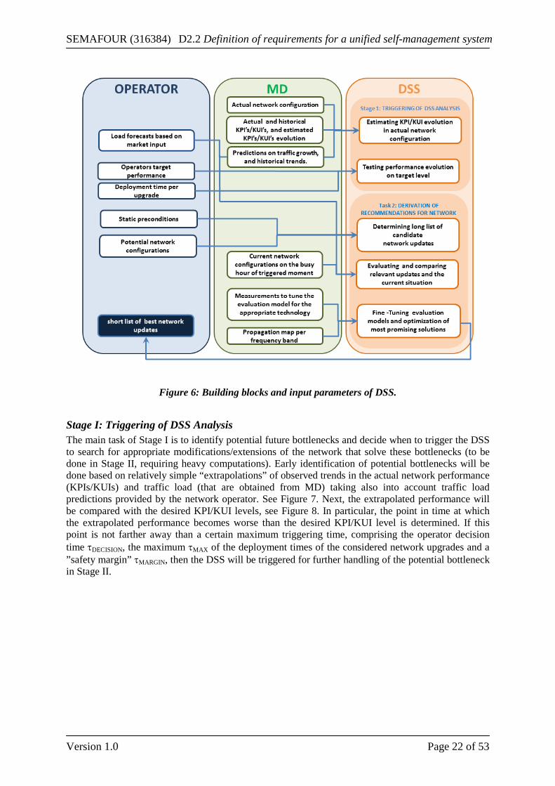
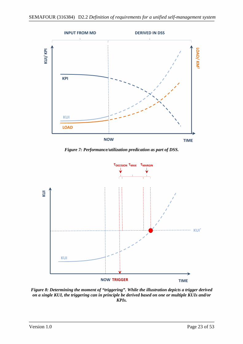
Stage I: Triggering of DSS Analysis The main task of Stage I is to identify potential future bottlenecks and decide when to trigger the DSS to search for appropriate modifications/extensions of the network that solve these bottlenecks (to be done in Stage II, requiring heavy computations). Early identification of potential bottlenecks will be done based on relatively simple “extrapolations” of observed trends in the actual network performance (KPIs/KUIs) and traffic load (that are obtained from MD) taking also into account traffic load predictions provided by the network operator. See Figure 7. Next, the extrapolated performance will be compared with the desired KPI/KUI levels, see Figure 8. In particular, the point in time at which the extrapolated performance becomes worse than the desired KPI/KUI level is determined. If this point is not farther away than a certain maximum triggering time, comprising the operator decision time τDECISION, the maximum τMAX of the deployment times of the considered network upgrades and a ”safety margin” τMARGIN, then the DSS will be triggered for further handling of the potential bottleneck in Stage II.
SEMAFOUR (316384) D2.2 Definition of requirements for a unified self-management system
Version 1.0 Page 23 of 53
Figure 7: Performance/utilization predication as part of DSS.
Figure 8: Determining the moment of “triggering”. While the illustration depicts a trigger derived on a single KUI, the triggering can in principle be derived based on one or multiple KUIs and/or
KPIs.
KPI
KUI
LOAD
TIMENOW
KUI/
KPI
LOAD/ KM
2
INPUT FROM MD DERIVED IN DSS
KUI
TIMENOW
KUI
KUI*
TRIGGER
τMAX τMARGINτDECISION
SEMAFOUR (316384) D2.2 Definition of requirements for a unified self-management system
Version 1.0 Page 24 of 53
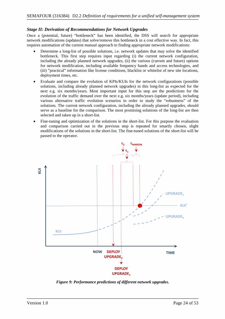
Stage II: Derivation of Recommendations for Network Upgrades Once a (potential, future) “bottleneck” has been identified, the DSS will search for appropriate network modifications (updates) that solve/remove this bottleneck in a cost effective way. In fact, this requires automation of the current manual approach to finding appropriate network modifications:
• Determine a long-list of possible solutions, i.e. network updates that may solve the identified bottleneck. This first step requires input regarding (i) the current network configuration, including the already planned network upgrades, (ii) the various (current and future) options for network modification, including available frequency bands and access technologies, and (iii) ”practical” information like license conditions, blacklist or whitelist of new site locations, deployment times, etc.
• Evaluate and compare the evolution of KPIs/KUIs for the network configurations (possible solutions, including already planned network upgrades) in this long-list as expected for the next e.g. six months/years. Most important input for this step are the predictions for the evolution of the traffic demand over the next e.g. six months/years (update period), including various alternative traffic evolution scenarios in order to study the “robustness” of the solutions. The current network configuration, including the already planned upgrades, should serve as a baseline for the comparison. The most promising solutions of the long-list are then selected and taken up in a short-list.
• Fine-tuning and optimization of the solutions in the short-list. For this purpose the evaluation and comparison carried out in the previous step is repeated for smartly chosen, slight modifications of the solutions in the short-list. The fine-tuned solutions of the short-list will be passed to the operator.
Figure 9: Performance predictions of different network upgrades.
KUI
TIMENOW
KUI
KUI*
UPGRADE1
UPGRADE2
τ2 τMARGIN
τ1
DEPLOYUPGRADE2
DEPLOYUPGRADE1
SEMAFOUR (316384) D2.2 Definition of requirements for a unified self-management system
Version 1.0 Page 25 of 53
Thus, the eventual output of the DSS will be a short list of best network updates, including detailed information about e.g. the resulting evolution of network KPIs/KUIs over time for given predictions/scenarios regarding the evolution of the traffic demand, see Figure 9. Based on additional information about e.g. equipment costs, labor costs and deployment time; the operator can make his choice to invest in the best network upgrade.
Remarks • An important issue is up to what extent the evaluation tools (typically based on “static”
snapshot simulation) should take into account the dynamic behavior of SON functions in the network. And, if so, how? For some SON functions the impact will be minor and needs not to be taken into account at all at the network planning level. However, other SON functions may have a huge impact on network performance, e.g. dynamic spectrum and interference management, automated traffic steering and active antenna systems. For these SON functions one may choose an appropriate ”average” setting of the specific parameters (e.g. antenna tilt) that are tuned by them, e.g. based on measurements over the past weeks/months. But, it may be that the behavior of these ”major” SON functions need to be incorporated even more explicitly/detailed in the evaluations.
• In determining appropriate network updates for a particular upcoming bottleneck the DSS may proactively take into account additional bottlenecks that are expected at a longer term.
• The models (propagation models, access network models, models for SON function behavior, etc.) used in the evaluation tool can be fine-tuned based on the continuous performance measurements and other network data provided by MD leading to a ”self-learning” evaluation tool.
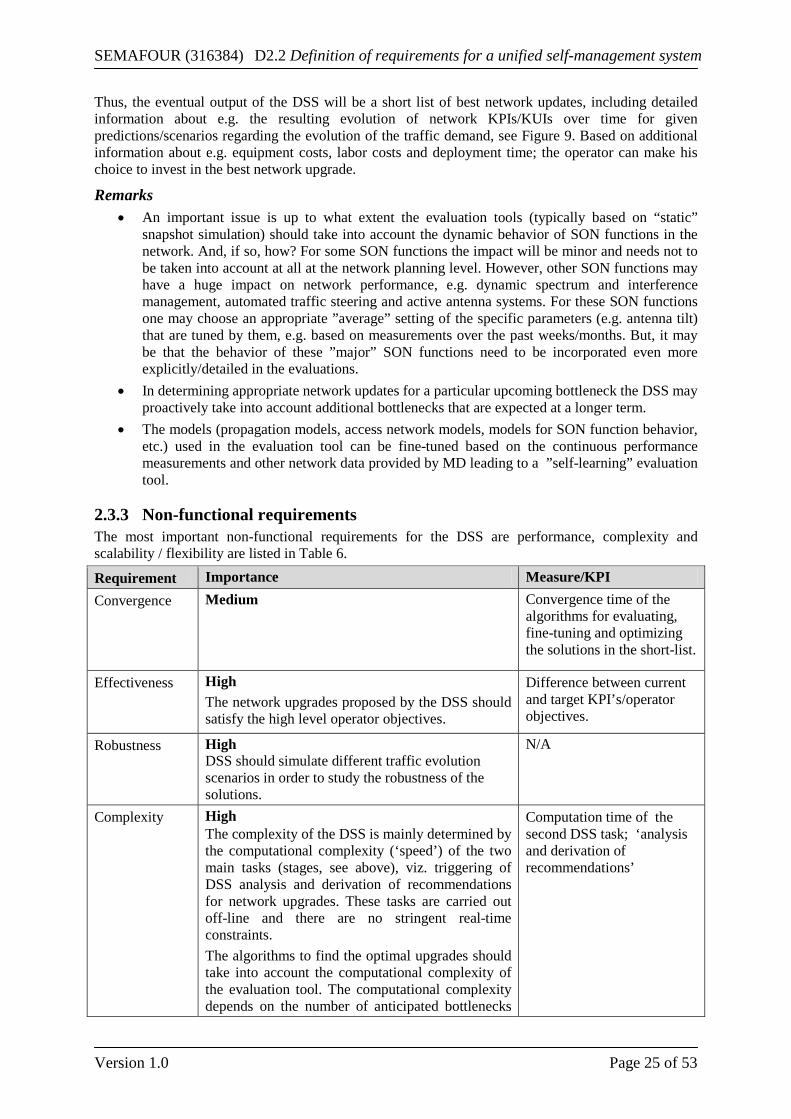
2.3.3 Non-functional requirements The most important non-functional requirements for the DSS are performance, complexity and scalability / flexibility are listed in Table 6.
Requirement Importance Measure/KPI Convergence Medium Convergence time of the
algorithms for evaluating, fine-tuning and optimizing the solutions in the short-list.
Effectiveness High The network upgrades proposed by the DSS should satisfy the high level operator objectives.
Difference between current and target KPI’s/operator objectives.
Robustness High DSS should simulate different traffic evolution scenarios in order to study the robustness of the solutions.
N/A
Complexity High The complexity of the DSS is mainly determined by the computational complexity (‘speed’) of the two main tasks (stages, see above), viz. triggering of DSS analysis and derivation of recommendations for network upgrades. These tasks are carried out off-line and there are no stringent real-time constraints. The algorithms to find the optimal upgrades should take into account the computational complexity of the evaluation tool. The computational complexity depends on the number of anticipated bottlenecks
Computation time of the second DSS task; ‘analysis and derivation of recommendations’
SEMAFOUR (316384) D2.2 Definition of requirements for a unified self-management system
Version 1.0 Page 26 of 53
that needs to be resolved, the number of upgrade types, and the granularity.
Scalability/flexibility
High The DSS should be designed modularly, i.e. in such a way that it requires minimal effort to cope with major changes in the network configuration. For example, deployment of a new RAT obviously requires modifications of the procedure/algorithm to establish a long-list of candidate network upgrades (in Stage II, see above) and also of the network simulator, but it should not require a complete new design of the DSS
Size of bottleneck area, number of potential upgrades maintained by DSS.
Interoperability Low The design of DSS should be independent of the design of MD.
Table 6: Summary of DSS non-functional requirements
2.4 Monitoring and Diagnosis The “Monitoring & Diagnosis” (MD) function shall provide access to network configuration and performance data to the PBSM, SONCO, and DSS. The data shall be provided at the level of abstraction used at the intermediate (system) level. The data may be processed with various levels of intensities, for which examples are given below. The degree of processing may actually determine the role that the MD function is going to have.
2.4.1 Definitions and Terminology In order to identify a suitable role of the MD, three different possible implementation variants have been proposed. They differ in complexity and the amount of tasks, the MD should be responsible for. The light-weight version provides means to access current and past network states as well as associated quality/performance readings. Whether the data will be linked to other sources (like CM or PM systems) via an overlay or will be stored in a dedicated database is of minor importance from the functional viewpoint. Apart from transforming the relevant data into suitable data at the intermediate (system) level, the MD function does not further process the configuration and performance data. The medium version additionally comprises statistical processing of the data. The results of statistical analysis are made available for PBSM, SONCO, and DSS. The medium version is likely to reduce the complexity of the respective processing capabilities of those functions. Similar to the light version, the medium version would not be responsible for evaluation and interpretation (in relation to quality targets/goals derived from the operator-policy level). The heavy-weight version offers extensive evaluation and interpretation capabilities. The MD function can then be used by the PBSM for evaluating the active policies and for determining a “desired state” of the network. The current network and its performance can be benchmarked against the desired state (indirectly through policy transformation) given by the network operator. The heavy-weight version is chosen for the project.
Interfaces We foresee interfaces between the MD and four other entities. PBSM The PBSM consults the MD about the current (and past) network configuration and performance in order to derive intermediate layer objectives and SON policies. The monitored and processed KPIs should reflect the objectives handled at intermediate layer. In particular, the addition of new objectives may entail the need for new KPI compositions. The MD may receive lists of updated requirements from the mapping entity between top and intermediate layer
SEMAFOUR (316384) D2.2 Definition of requirements for a unified self-management system
Version 1.0 Page 27 of 53
when new high-level objectives are transformed into intermediate layer objectives. If, for example, a KPI for hand-over success rate has not been monitored, it will become important when a new high-level objective concerning mobility robustness is introduced. SONCO The information acquisition and processing part of the SONCO receives KPI data corresponding to the observed SON functions. Depending on its information processing capabilities, the SONCO may be supported in detecting unnatural oscillations in the network by the MD function. DSS The MD serves as a data source of the DSS. The DSS accesses KPI values as well as seasonal and trend information for the corresponding data history. To a possibly small extent, the MD may provide predictions for the evolution of the network status and its performance for hours, days, or even a few weeks. Network Management System The MD communicates with the network management system (PM and CM systems) to gather network information, available measurements or KPIs, and failure information if required. If the system permits, the MD may adjust the granularity of selected information streams to account for different requirements of the processing tasks within the MD.
2.4.2 Business Requirements The MD itself does not have to meet specific business requirements as it is a service function to other parts of the infrastructure. The MD acts as an internal support function, which provides processed network data to the PBSM, SONCO, and DSS. In comparison with a system design in which each of these entities itself is responsible for gathering and processing data, the centralization and unification through the MD enables the reuse of processed data, thus reducing overall processing effort. Moreover, the MD delivers business values indirectly through supporting the entities of the Integrated SON Management.
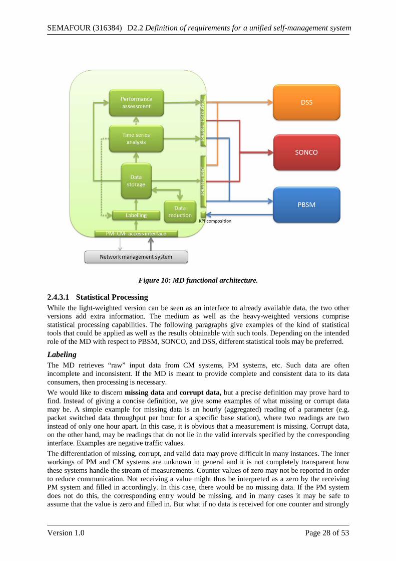
2.4.3 Functional Requirements Monitoring and diagnosis includes two major tasks: the statistical processing of “raw” performance and configuration data from the network, and the assessment of this data with respect to the system performance, put in relation to the goals and objectives defined by the operator. The functional architecture block diagram for the MD function is depicted in Figure 10, and the two MD tasks are explained in the following paragraphs.
SEMAFOUR (316384) D2.2 Definition of requirements for a unified self-management system
Version 1.0 Page 28 of 53
Figure 10: MD functional architecture.
2.4.3.1 Statistical Processing While the light-weighted version can be seen as an interface to already available data, the two other versions add extra information. The medium as well as the heavy-weighted versions comprise statistical processing capabilities. The following paragraphs give examples of the kind of statistical tools that could be applied as well as the results obtainable with such tools. Depending on the intended role of the MD with respect to PBSM, SONCO, and DSS, different statistical tools may be preferred.
Labeling The MD retrieves “raw” input data from CM systems, PM systems, etc. Such data are often incomplete and inconsistent. If the MD is meant to provide complete and consistent data to its data consumers, then processing is necessary. We would like to discern missing data and corrupt data, but a precise definition may prove hard to find. Instead of giving a concise definition, we give some examples of what missing or corrupt data may be. A simple example for missing data is an hourly (aggregated) reading of a parameter (e.g. packet switched data throughput per hour for a specific base station), where two readings are two instead of only one hour apart. In this case, it is obvious that a measurement is missing. Corrupt data, on the other hand, may be readings that do not lie in the valid intervals specified by the corresponding interface. Examples are negative traffic values. The differentiation of missing, corrupt, and valid data may prove difficult in many instances. The inner workings of PM and CM systems are unknown in general and it is not completely transparent how these systems handle the stream of measurements. Counter values of zero may not be reported in order to reduce communication. Not receiving a value might thus be interpreted as a zero by the receiving PM system and filled in accordingly. In this case, there would be no missing data. If the PM system does not do this, the corresponding entry would be missing, and in many cases it may be safe to assume that the value is zero and filled in. But what if no data is received for one counter and strongly
SEMAFOUR (316384) D2.2 Definition of requirements for a unified self-management system
Version 1.0 Page 29 of 53
correlated counters are reported with values that basically rule out the possibility of the missing value being zero? Filling this gap with a zero might then lead to wrong conclusions in the subsequent processing chain. In fact, if in this example a zero would have been reported by the PM system, the data may be considered corrupt. With the above in mind, the SEMAFOUR project will likely agree on what are considered missing and corrupt data (within the scope of MD). Once such definitions are available, we could expect the MD to label data as “incomplete” whenever missing input is detected to prevent misinterpretation. By combining historic data from the time series as well as correlation to other measured data, it may be possible to suggest reasonable reconstructions for missing parts. The corresponding entries may be labeled “estimate.” The MD can try to detect corrupt data and proceed similarly as with missing data. This may be obvious in some cases (negative values, where only positive values are admitted). In other situations the distinction between “seemingly corrupt data” and pathologic network behavior may be hard to make as implied above. Gaussian regression is one example of a statistical tool available for filling in missing data and checking for data corruption. A Gaussian regression tries to inter-/extrapolate given measurements based on prescribed underlying correlation models. These correlation models determine how each measurement is correlated to each inter-/extrapolation, e.g., a missing measurement for CS traffic from a Monday at 9 pm is strongly correlated to the measured data at 8 pm and 10 pm on the same day as well as to those of other Mondays at the same time (provided this is an “ordinary” Monday).
Time Series Analysis As stated in Deliverable D2.1 [1], the DSS is supposed to identify problems within the network and make sophisticated proposals during the observation time period. The MD may support the DSS in this respect by statistically analyzing the dynamics of selected parameters. By suitably fitting parameterized models, it is possible to extract relevant features such as seasonal behavior or trends. The MD may furthermore analyze the time series and split it into several parts capturing effects such as daily fluctuations, different behavior during weekends, and noise. These parts may be analyzed separately, making it possible to discern “regular behavior” and “unusual events”. In this context, for example, Gaussian regression can be employed to determine values for parameters describing seasonal behavior, trends, and noise according to the measured data. This also allows for detecting major variations from the “regular behavior” (i.e. behavior predicted by the model representing the data). Examples of other statistical tools that may be helpful are linear regression, moving averages, and Kalman filters.
Data Reduction Providing network configuration and performance data for a longer period of time leads to the question of lossy data compression. Nowadays, a compression hierarchy is often used. For some time back, typically a few weeks, all raw data are stored. As the data ages, data points are aggregated (e.g. averaged or re-sampled) in order to reduce the data volume. This aggregation process may have several stages. After some longer time span, say one year, data points are simply discarded. This procedure allows for adapting the data aggregation / reduction to the available storage. There are, however, cases where this process purges data too early. Take the example of an annually recurring event such as a fair or some large festivity. If network traffic and performance readings from the preceding event were still available in full detail, then something like the following would be possible: (a) Compare the changes in the traffic profiles before, during, and after the event and identify the traffic delta caused by that event; (b) Estimate the general traffic growth from the last year to this year; (c) Take a similar event that has recently recurred an compare how the traffic deltas for this year differs from the one of the previous year; (d) Populate a model to extrapolate the traffic delta from last year to this year for the upcoming event. The result of this exercise is considered valuable input for the DSS-NE. If the data is purged or excessively aggregated too early, however, such input cannot be made available.
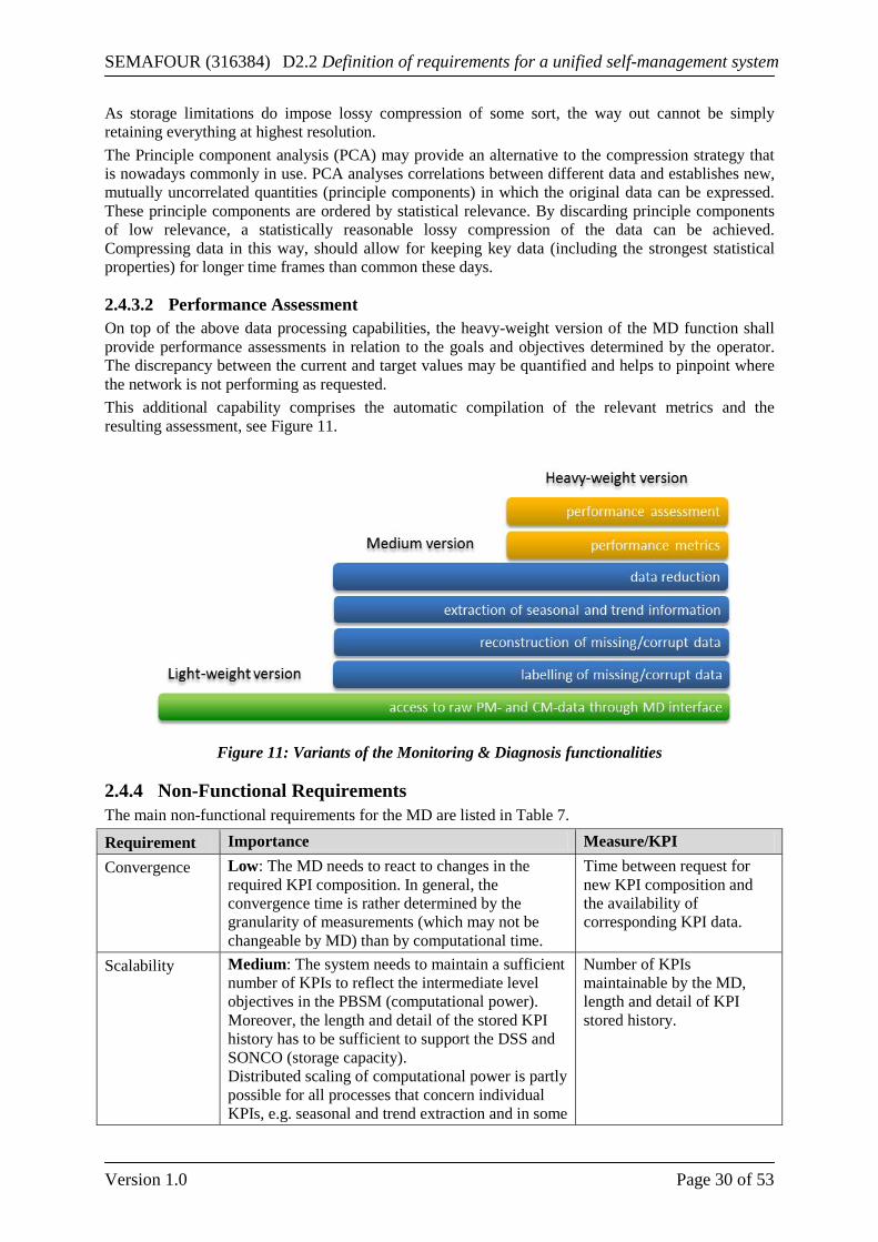
SEMAFOUR (316384) D2.2 Definition of requirements for a unified self-management system
Version 1.0 Page 30 of 53
As storage limitations do impose lossy compression of some sort, the way out cannot be simply retaining everything at highest resolution. The Principle component analysis (PCA) may provide an alternative to the compression strategy that is nowadays commonly in use. PCA analyses correlations between different data and establishes new, mutually uncorrelated quantities (principle components) in which the original data can be expressed. These principle components are ordered by statistical relevance. By discarding principle components of low relevance, a statistically reasonable lossy compression of the data can be achieved. Compressing data in this way, should allow for keeping key data (including the strongest statistical properties) for longer time frames than common these days.
2.4.3.2 Performance Assessment On top of the above data processing capabilities, the heavy-weight version of the MD function shall provide performance assessments in relation to the goals and objectives determined by the operator. The discrepancy between the current and target values may be quantified and helps to pinpoint where the network is not performing as requested. This additional capability comprises the automatic compilation of the relevant metrics and the resulting assessment, see Figure 11.
Figure 11: Variants of the Monitoring & Diagnosis functionalities
2.4.4 Non-Functional Requirements The main non-functional requirements for the MD are listed in Table 7.
Requirement Importance Measure/KPI Convergence Low: The MD needs to react to changes in the
required KPI composition. In general, the convergence time is rather determined by the granularity of measurements (which may not be changeable by MD) than by computational time.
Time between request for new KPI composition and the availability of corresponding KPI data.
Scalability Medium: The system needs to maintain a sufficient number of KPIs to reflect the intermediate level objectives in the PBSM (computational power). Moreover, the length and detail of the stored KPI history has to be sufficient to support the DSS and SONCO (storage capacity). Distributed scaling of computational power is partly possible for all processes that concern individual KPIs, e.g. seasonal and trend extraction and in some
Number of KPIs maintainable by the MD, length and detail of KPI stored history.
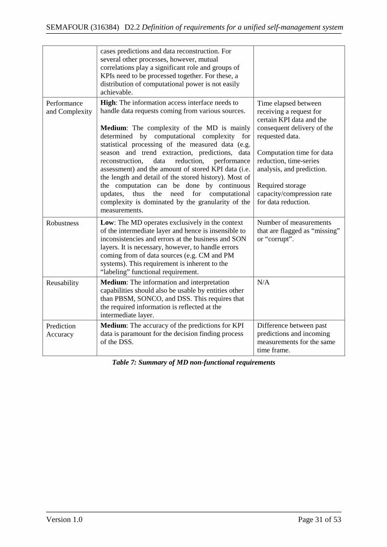
SEMAFOUR (316384) D2.2 Definition of requirements for a unified self-management system
Version 1.0 Page 31 of 53
cases predictions and data reconstruction. For several other processes, however, mutual correlations play a significant role and groups of KPIs need to be processed together. For these, a distribution of computational power is not easily achievable.
Performance and Complexity
High: The information access interface needs to handle data requests coming from various sources. Medium: The complexity of the MD is mainly determined by computational complexity for statistical processing of the measured data (e.g. season and trend extraction, predictions, data reconstruction, data reduction, performance assessment) and the amount of stored KPI data (i.e. the length and detail of the stored history). Most of the computation can be done by continuous updates, thus the need for computational complexity is dominated by the granularity of the measurements.
Time elapsed between receiving a request for certain KPI data and the consequent delivery of the requested data. Computation time for data reduction, time-series analysis, and prediction. Required storage capacity/compression rate for data reduction.
Robustness Low: The MD operates exclusively in the context of the intermediate layer and hence is insensible to inconsistencies and errors at the business and SON layers. It is necessary, however, to handle errors coming from of data sources (e.g. CM and PM systems). This requirement is inherent to the “labeling” functional requirement.
Number of measurements that are flagged as “missing” or “corrupt”.
Reusability Medium: The information and interpretation capabilities should also be usable by entities other than PBSM, SONCO, and DSS. This requires that the required information is reflected at the intermediate layer.
N/A
Prediction Accuracy
Medium: The accuracy of the predictions for KPI data is paramount for the decision finding process of the DSS.
Difference between past predictions and incoming measurements for the same time frame.
Table 7: Summary of MD non-functional requirements
SEMAFOUR (316384) D2.2 Definition of requirements for a unified self-management system
Version 1.0 Page 32 of 53
3 Multi-RAT and Multi-Layer SON Use Cases In SEMAFOUR deliverable D2.1 [1] a set of SON use cases has been defined. Since then, the scope and definition of the use cases have evolved. In particular, the multi-flow use case will not be developed in this deliverable as studying this use case in SEMAFOUR is still an open issue. Only the SON use cases that will be further investigated in the project are addressed in this section:
• Dynamic Spectrum Allocation and Interference Management • Multi-layer LTE/Wi-Fi Traffic Steering • Idle Mode Handling • High Mobility • Active Antenna Systems
Each of these use cases is briefly introduced in the following sections, with an explanation of the use case goals, the business requirements, and the functional and non-functional requirements of the use case.
3.1 Dynamic Spectrum Allocation and Interference Management This use case is about algorithms and strategies for Dynamic Spectrum Allocation (DSA) and Interference Management (IM) in multi-layer and multi-RAT environments. Traffic peaks and busy hour traffic conditions can be observed at different places (spatial dimension) and at different times (temporal dimension) of the day. To avoid overload or under-utilization of carriers a lightly-utilized carrier frequency could be (re-) assigned to a Base Station that is in or near to overload. This applies in an LTE multi-layer network by dynamically assigning carriers to the different LTE layers (macro-micro-pico-femto) as well as in a multi-RAT network; in the latter DSA means that existing GSM or UMTS spectrum may be dynamically allocated to LTE (e.g., up to 10 MHz bandwidth) and vice-versa. The possibility of switching to another technology is subject to the condition that the UE is able to support the selected frequency bands as well as the selected radio access technologies. In LTE dynamic spectrum allocation is complemented by interference management. Typical actions of interference management are the assignment of bandwidth within the assigned carriers, the dynamic changing of the bandwidth partitioning/usage between LTE macro and pico/femto layers, and the adjustment of the transmitting power of the Base Station. Three dynamic spectrum allocation sub-cases are considered:
• Intra-RAT Case A: Dynamic spectrum allocation within an LTE network across different layers. Only eNodeBs fully under control of the network operator are considered, e. g., no femto cells.
• Intra-RAT Case B: Same as intra-RAT case A, but with femto cells. • Inter-RAT Case: Dynamic spectrum allocation for the multi-layer LTE network including
bandwidth re-farming across different 3GPP technologies.
3.1.1 Business Requirements The business requirements are summarized in Table 8. Four requirements are addressed: OPEX, CAPEX, Spectrum efficiency and energy efficiency. The latter two are also related to CAPEX (w.r.t. to investment into spectrum) and OPEX (w.r.t. to energy cost) as well. The different requirements are ranked by their importance and also measure relevant for the requirement is given. In this use case spectrum efficiency is seen as the major point, which can be influenced by DSA, whereas CAPEX and energy efficiency are seen with medium importance only. This is because educing CAPEX and energy consumption are not the main driver for this use case, but DSA offers some “side” gain as well also w. r. t. to these requirements.
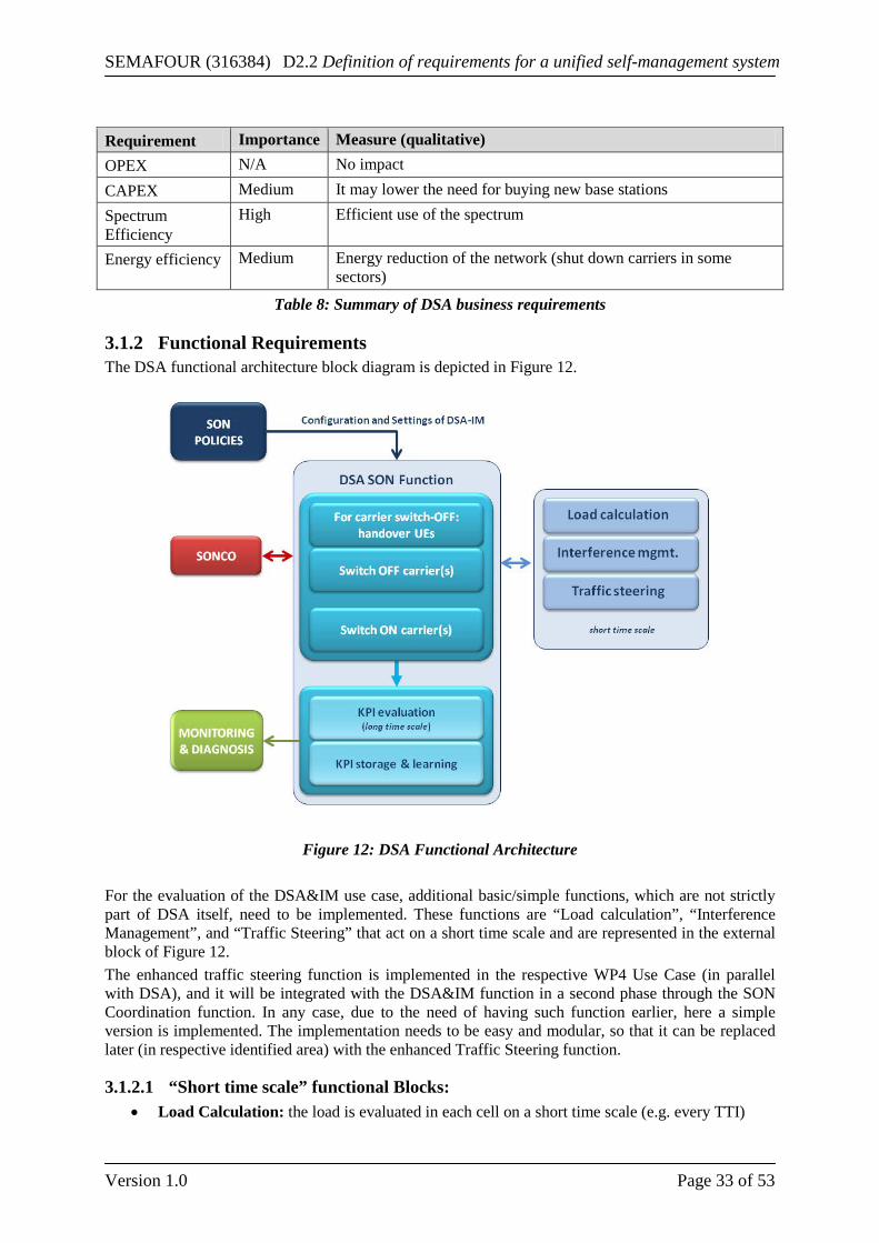
SEMAFOUR (316384) D2.2 Definition of requirements for a unified self-management system
Version 1.0 Page 33 of 53
Requirement Importance Measure (qualitative) OPEX N/A No impact CAPEX Medium It may lower the need for buying new base stations Spectrum Efficiency
High Efficient use of the spectrum
Energy efficiency Medium Energy reduction of the network (shut down carriers in some sectors)
Table 8: Summary of DSA business requirements
3.1.2 Functional Requirements The DSA functional architecture block diagram is depicted in Figure 12.
Figure 12: DSA Functional Architecture
For the evaluation of the DSA&IM use case, additional basic/simple functions, which are not strictly part of DSA itself, need to be implemented. These functions are “Load calculation”, “Interference Management”, and “Traffic Steering” that act on a short time scale and are represented in the external block of Figure 12. The enhanced traffic steering function is implemented in the respective WP4 Use Case (in parallel with DSA), and it will be integrated with the DSA&IM function in a second phase through the SON Coordination function. In any case, due to the need of having such function earlier, here a simple version is implemented. The implementation needs to be easy and modular, so that it can be replaced later (in respective identified area) with the enhanced Traffic Steering function.
3.1.2.1 “Short time scale” functional Blocks: • Load Calculation: the load is evaluated in each cell on a short time scale (e.g. every TTI)
SEMAFOUR (316384) D2.2 Definition of requirements for a unified self-management system
Version 1.0 Page 34 of 53
• Interference Management is always active and acts between cells sharing the same carrier(s) (e.g. 1800MHz, Macro-Macro, Macro-Micro/Pico, Micro/Pico – Micro/Pico)
• Traffic Steering: here only Load Balance is considered (no service-QoS based). Load balancing takes place when the load in a given cell is higher than a given threshold (i.e. source_cell_load > thre_high) for a given time while another target cell has much lower load (target_cell_load < thre_low). The target cell may take part of the traffic of the congested cell improving UE and network performances. Traffic Steering acts on medium time scale (e.g. tens of seconds).
3.1.2.2 DSA functional Blocks: • KPI Evaluation: UE KPIs as well as Cell KPIs (e.g. average throughput, Spectrum efficiency
of the cell) are evaluated on long time scale (e.g. 15 min, hour, day) • Store & Learning: Cell and UE KPIs are stored on daily basis, so that the system learns
whether traffic in various areas has a repetitive or periodic behavior. This can be calculated on daily or weekly basis (e.g. in a certain business area the traffic may be high at day and low at night time in week days). For this functional block methods of the MD use case in WP5 may be used, see section 2.3.
• Carrier switch off: If KPIs indicate that for a given period of time (in the order of hours, days) a given cell configured with multiple carriers is scarcely used, DSA may decide to switch one carrier OFF. If some UEs are still connected to that carrier, they need to be handed over using traffic steering mechanisms.
• Carrier switch on: If KPIs indicate that the traffic is increasing to a point where the current carriers become congested (despite Traffic Steering) or they cannot cope with such a traffic increase, DSA will command a carrier switch ON. This will happen in places where the high traffic area is located close to a “dormant” cell, carrier switch ON must react quite fast (to be decided how fast, e.g. minutes, tens of minutes).
• DSA: Spectrum reassignment algorithm must consider UE support of various LTE frequencies. For the MRAT case the UE may have the following capabilities: support of 2G only, 2G and 3G, 2G+3G+LTE.
3.1.2.3 Input Data to DSA: • Initial (current) carrier allocation per cell; • Traffic steering parameters: high and low load thresholds; • Interference management parameters; • UE support of various LTE frequencies. For the multi-RAT case, the UE may have the
following capabilities: support of 2G only, 2G and 3G, 2G+3G+LTEThis data should be derived from the PM data;
• Carrier utilization per cell for all allocated carriers.
3.1.2.4 Output Data form DSA • Traffic load in each cell and its time variation (model/ intensity, etc.). E.g. cell KPIs (load,
average cell throughput) and UE KPIs (user satisfaction, average throughput per user) • List of carriers and corresponding cells for switching off • List of carriers and corresponding cells for switching on
3.1.2.5 SON coordination DSA coordinates with the other SON functions through the SONCO. This coordination is two-fold: 1. Through coordination potential conflicts have to be resolved; 2. Since the AAS and traffic steering use cases have similar targets active coordination with these use cases is also required. For monitoring the
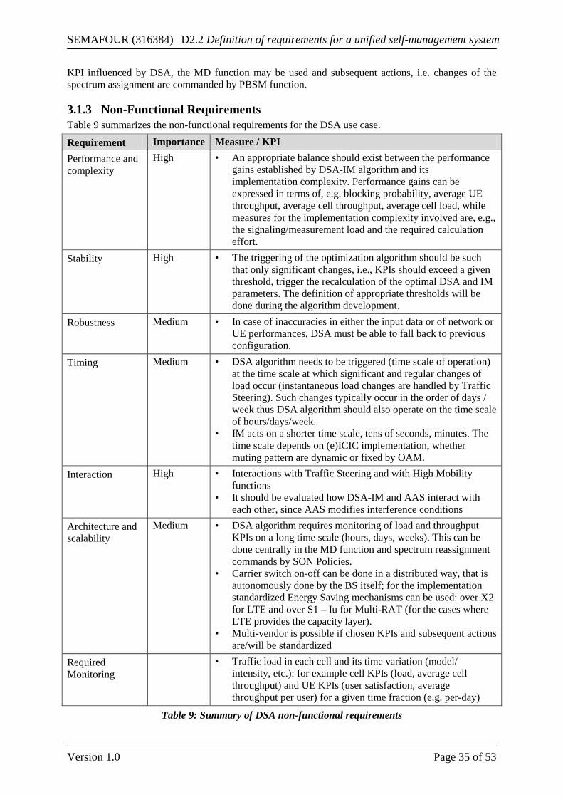
SEMAFOUR (316384) D2.2 Definition of requirements for a unified self-management system
Version 1.0 Page 35 of 53
KPI influenced by DSA, the MD function may be used and subsequent actions, i.e. changes of the spectrum assignment are commanded by PBSM function.
3.1.3 Non-Functional Requirements Table 9 summarizes the non-functional requirements for the DSA use case.
Requirement Importance Measure / KPI Performance and complexity
High • An appropriate balance should exist between the performance gains established by DSA-IM algorithm and its implementation complexity. Performance gains can be expressed in terms of, e.g. blocking probability, average UE throughput, average cell throughput, average cell load, while measures for the implementation complexity involved are, e.g., the signaling/measurement load and the required calculation effort.
Stability High • The triggering of the optimization algorithm should be such that only significant changes, i.e., KPIs should exceed a given threshold, trigger the recalculation of the optimal DSA and IM parameters. The definition of appropriate thresholds will be done during the algorithm development.
Robustness Medium • In case of inaccuracies in either the input data or of network or UE performances, DSA must be able to fall back to previous configuration.
Timing Medium • DSA algorithm needs to be triggered (time scale of operation) at the time scale at which significant and regular changes of load occur (instantaneous load changes are handled by Traffic Steering). Such changes typically occur in the order of days / week thus DSA algorithm should also operate on the time scale of hours/days/week.
• IM acts on a shorter time scale, tens of seconds, minutes. The time scale depends on (e)ICIC implementation, whether muting pattern are dynamic or fixed by OAM.
Interaction High • Interactions with Traffic Steering and with High Mobility functions
• It should be evaluated how DSA-IM and AAS interact with each other, since AAS modifies interference conditions
Architecture and scalability
Medium • DSA algorithm requires monitoring of load and throughput KPIs on a long time scale (hours, days, weeks). This can be done centrally in the MD function and spectrum reassignment commands by SON Policies.
• Carrier switch on-off can be done in a distributed way, that is autonomously done by the BS itself; for the implementation standardized Energy Saving mechanisms can be used: over X2 for LTE and over S1 – Iu for Multi-RAT (for the cases where LTE provides the capacity layer).
• Multi-vendor is possible if chosen KPIs and subsequent actions are/will be standardized
Required Monitoring
• Traffic load in each cell and its time variation (model/ intensity, etc.): for example cell KPIs (load, average cell throughput) and UE KPIs (user satisfaction, average throughput per user) for a given time fraction (e.g. per-day)
Table 9: Summary of DSA non-functional requirements
SEMAFOUR (316384) D2.2 Definition of requirements for a unified self-management system
Version 1.0 Page 36 of 53
3.2 Multi-layer LTE/Wi-Fi Traffic Steering Use Case This use case targets solutions for QoS based LTE/Wi-Fi traffic steering techniques in dense urban deployments. Such deployments are assumed to comprise outdoor LTE base stations offering macro, micro and pico coverage and additionally indoor/outdoor Wi-Fi access points. The automatic integration and management of the available hierarchy layers, i.e. LTE macro, micro and pico cells, and radios, i.e. LTE and Wi-Fi, are within the scope of this use case. The overall goal is to improve the end user experience and the network performance via a more efficient utilization of Wi-Fi and cellular network assets while minimizing additional complexity. Different degrees of operator control over the Wi-Fi network and availability of Wi-Fi information at the cellular nodes are considered. Today, Wi-Fi network discovery, selection and access are typically user-controlled via a connection manager utility installed at the client side (ad-hoc connectivity). This connection manager will likely access the user’s preferred access points whenever these are available. This leaves the mobile operators with limited control over the cellular offloading to Wi-Fi and it leads to degraded QoS for the end user when Wi-Fi experiences high load and poor coverage conditions. On top of standardized semi-static offloading solutions, several proprietary solutions exist to enable more intelligent offloading to Wi-Fi such as NSN Smart WLAN Connectivity [2], Ericsson Network Integrated Wi-Fi (ENIW) [3] and Qualcomm’s Connectivity Engine [4]. However, the device behaviors remain diverse, uncertain and unreliable. This study will assess the impact of different degrees of mobile network operator (MNO) control over the Wi-Fi network and availability of Wi-Fi information at the cellular nodes. It will assume as baseline today’s knowledge which is limited to the existence and usability of Wi-Fi access points (AP), in addition to semi-static operator-defined network access policies. On the other end of the scale, the upper bound case will be evaluated where complete control and information set is available, i.e., Wi-Fi acts as a “3GPP-alike” layer. Few selected cases in between will be also considered.
3.2.1 Business Requirements Several business requirements have been identified for traffic steering as listed in the following table:
Requirement Importance Measure OPEX reduction N/A. No impact. CAPEX reduction
Medium It may lower the need for buying new base stations with increased spectral efficiency (bits/Hertz).
End user satisfaction
High Users experience better QoE/QoS due to improved perceptive service quality, e.g. response times and throughput of their applications, higher user throughput at cell edge.
Table 10: Summary of TS business requirements
3.2.2 Functional Requirements Traffic Steering (TS) functional architecture block diagram is depicted in Figure 13.
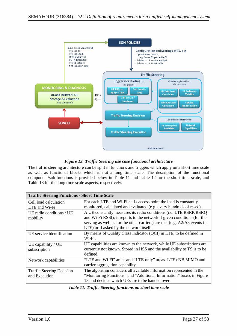
SEMAFOUR (316384) D2.2 Definition of requirements for a unified self-management system
Version 1.0 Page 37 of 53
Figure 13: Traffic Steering use case functional architecture
The traffic steering architecture can be split in functions and triggers which apply on a short time scale as well as functional blocks which run at a long time scale. The description of the functional component/sub-functions is provided below in Table 11 and Table 12 for the short time scale, and Table 13 for the long time scale aspects, respectively. Traffic Steering Functions - Short Time Scale Cell load calculation LTE and Wi-Fi
For each LTE and Wi-Fi cell / access point the load is constantly monitored, calculated and evaluated (e.g. every hundreds of msec).
UE radio conditions / UE mobility
A UE constantly measures its radio conditions (i.e. LTE RSRP/RSRQ and Wi-Fi RSSI); it reports to the network if given conditions (for the serving as well as for the other carriers) are met (e.g. A2/A3 events in LTE) or if asked by the network itself.
UE service identification By means of Quality Class Indicator (QCI) in LTE, to be defined in Wi-Fi.
UE capability / UE subscription
UE capabilities are known to the network, while UE subscriptions are currently not known. Stored in HSS and the availability to TS is to be defined.
Network capabilities “LTE and Wi-Fi” areas and “LTE-only” areas. LTE eNB MIMO and carrier aggregation capability.
Traffic Steering Decision and Execution
The algorithm considers all available information represented in the “Monitoring Functions” and “Additional Information” boxes in Figure 13 and decides which UEs are to be handed over.
Table 11: Traffic Steering functions on short time scale
SEMAFOUR (316384) D2.2 Definition of requirements for a unified self-management system
Version 1.0 Page 38 of 53
Traffic Steering Triggers - Short Time Scale UE RSS < THR and / or UE RSRP < THR
If the Received Signal Strength (RSS) in Wi-Fi and / or the Reference Signal Received Power (RSRP) in LTE is below a configured threshold (THR).
Cell Load > THR If the load in a LTE/Wi-Fi Cell is above a configured threshold (THR) (e.g. 70%).
Call Setup / Handover If policy is based on e.g. QoS, every time a call is established (or condition for handover is met) the TS engine needs to route the call according to the given policy.
Table 12: Traffic Steering triggers on short time scale Functional Block - Long Time Scale UE and Network KPIs Storage and Evaluation:
KPIs are stored on long time scale (per hours/ day/ week) and analyzed for potential change of TS Policies Per UE KPIs and per-cell KPIs.
Configuration and Settings of TS
• Optimization criteria, e.g. average or 5th percentile user throughput
• Policies with regard to service • QoS Policies with regard to user profile
Table 13: Traffic Steering functional blocks on long time scale
3.2.3 Non-Functional Requirements The most important feature of traffic steering is the capability to be responsive to the dynamic behavior of real-time network load conditions steering users to the radio access / node which is more desirable than others in a given geographical area, avoiding conditions of congestion or under-utilization, while avoiding oscillations and undesired system behavior. The identified non-functional requirements for traffic steering as listed in the following table:
Requirement Importance Measure / KPI Performance and complexity
High High performance gains are expected for dynamic LTE/Wi-Fi traffic steering due to better distributions of users among layers and technologies. Those gains can be expressed in terms of, e.g. blocking probability, average UE throughput, average cell throughput, average cell load. Those high performance gains shall be achieved while minimizing additional network complexity in terms of number of added sub-components and the easiness in their parameterization.
Stability High TS has to avoid oscillations and undesired behavior which can be expressed with number of ping-pongs between LTE and Wi-Fi, number of steering decisions to wrong cell / node.
Robustness Medium In case of faulty configuration or bad network or UE performance, the algorithm must be able to quickly adjust (in terms of tens of seconds/minutes).
Interaction High TS has interaction with all use cases. In particular the High Mobility (HM) use case also studies which layer/RAT a UE should be assigned to. DSA has to consider TS in its logic (easier version of TS is embedded in DSA). The interaction between TS and AAS is for further study.
Architectural and High Due to the dynamic nature of traffic, a distributed architecture from
SEMAFOUR (316384) D2.2 Definition of requirements for a unified self-management system
Version 1.0 Page 39 of 53
Scalability the cellular side is considered preferential for traffic steering schemes to quickly adjust to the traffic changes (in terms of tens of seconds/minutes). However, from a Wi-Fi point of view, a centralized architecture may be considered where a group of Wi-Fi access points (irrespective of their radio coverage areas) may be controlled under the cellular network. As an alternative a centralized architecture may also be considered where a central point coordinates both technologies. Especially in the centralized scheme, scalability issues have to be considered.
Table 14: Summary of TS non-functional requirements
3.3 Idle Mode Handling Use Case The use case Idle Mode Handling (IMH) focuses on the optimization of the cell reselection procedure so that the UE always camps on the most appropriate cell. By camping on a suitable cell, connection times are reduced and subsequent unnecessary handovers once the user becomes active are avoided. This will be a pro-active load balancing mechanism, similar to mobility load balancing (MLB) or traffic steering (TS) for CONNECTED mode. Most MLB and TS schemes focus on the CONNECTED mode, where the user is active and RLFs and call drops are likely to occur. However, the IDLE mode should not be neglected just due the lack of an active session. Distributing users between different layers and RATs while in IDLE mode, will not degrade the performance of MRO in CONNECTED mode since there will be no direct conflict between the control parameters. If well distributed while in IDLE, the number of handovers subsequent to the user switching to CONNECTED mode will be minimized. This will translate into signaling, packet loss and delay reduction which directly affect the QoS for the user and diminish the strain on the network.
3.3.1 Business Requirements Several business requirements have been identified for idle mode handling as listed in the following table:
Requirement Importance Measure OPEX reduction N/A No impact. CAPEX reduction
Medium / Low
IMH will mainly reduce the required network signaling capacity. In case signaling becomes a bottleneck in the system such reduction will leads to CAPEX reduction.
End-user benefit Medium While QoS/ QoE may be improved by Idle mode traffic steering by reducing connection setup times and subsequent HOs, the main gain will come from TS in CONNECTED mode. In turn, IMH will reduce the costs in terms of signaling.
Table 15: Summary of IMH business requirements
3.3.2 Functional Requirements The functional architecture block diagram of the idle mode handling use case is depicted in Figure 14.
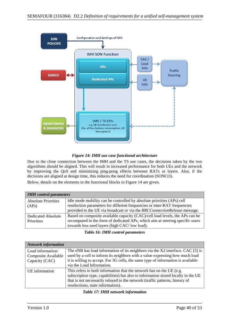
SEMAFOUR (316384) D2.2 Definition of requirements for a unified self-management system
Version 1.0 Page 40 of 53
Figure 14: IMH use case functional architecture
Due to the close connection between the IMH and the TS use cases, the decisions taken by the two algorithms should be aligned. This will result in increased performance for both UEs and the network by improving the QoS and minimizing ping-pong effects between RATs or layers. Also, if the decisions are aligned at design time, this reduces the need for coordination (SONCO). Below, details on the elements in the functional blocks in Figure 14 are given. IMH control parameters Absolute Priorities (APs)
Idle mode mobility can be controlled by absolute priorities (APs) cell reselection parameters for different frequencies or inter-RAT frequencies provided to the UE via broadcast or via the RRCConnectionRelease message.
Dedicated Absolute Priorities
Based on composite available capacity (CAC)/cell load levels, the APs can be recomputed in the form of dedicated APs, which aim at steering specific users towards less used layers (high CAC/ low load).
Table 16: IMH control parameters Network information Load information/ Composite Available Capacity (CAC)
The eNB has load information of its neighbors via the X2 interface. CAC [5] is used by a cell to inform its neighbors with a value expressing how much load it is willing to accept. For 3G cells, the same type of information is available via the Load Information.
UE information This refers to both information that the network has on the UE (e.g. subscription type, capabilities) but also to information stored locally in the UE that is not necessarily relayed to the network (traffic patterns, history of reselections, state information).
Table 17: IMH network information
SEMAFOUR (316384) D2.2 Definition of requirements for a unified self-management system
Version 1.0 Page 41 of 53
IMH KPIs examples UE distribution UE distribution across RATs and layers in IDLE and CONNECTED mode. Costs Costs may refer to number of Handovers (HO) or battery consumption of the
UE due to measurements. UE throughput / latency
Average or instantaneous UE throughput; connection setup times.
Table 18: IMH KPI examples
3.3.3 Non-functional requirements In the following Table 19 the non-functional requirements for the IMH use case are listed.
Requirement Importance Measure/KPI Convergence Medium The algorithm should converge to a solution and not introduce
additional performance fluctuations. Complexity High The algorithm should be constructed in such a way that the needed
function blocks are easy to implement in both eNB and UE. Performance High The use of the IMH algorithm should improve performance of the
UE and network. Interaction High The IMH is closely connected with the TS use case. Thus the two
algorithms should be aligned in order to provide best results. Robustness Medium In case of errors in the configuration or degrading UE or network
performance, the algorithm should be able to react quickly in solving the situation (in terms of tens of seconds/minutes).
Table 19: Summary of IMH non-functional requirements
3.4 High Mobility Use Case The high mobility use case optimizes the handover performance of highly mobile users in situations where this poses a noticeable impact on the UE and network performance [1]. These situations can arise when there is either a dense deployment of cells or when users move through the network at a high speed. In these cases a reduction of the QoS and an increase of the signaling overhead in the core network might occur [8], also the number of dropped calls might increase due to the more frequent handovers. The objective of this use case is to develop a SON function that improves the QoS of the highly mobile users and reduces the number of call drops and the signaling overhead in the core network by reducing the number of handovers and optimizing the handover timing of the users by steering users to cells on which they can be camped for a longer time.
3.4.1 Business Requirements As the high-mobility use case mainly focuses on improving the QoS of particular users its main benefit will be a higher user satisfaction.
Requirement Importance Measure OPEX reduction Low Small OPEX reduction CAPEX reduction
Low Small CAPEX reduction
End-user benefit High A higher QoS of the highly mobile users and a decrease of call drops
Table 20: Summary of HM business requirements
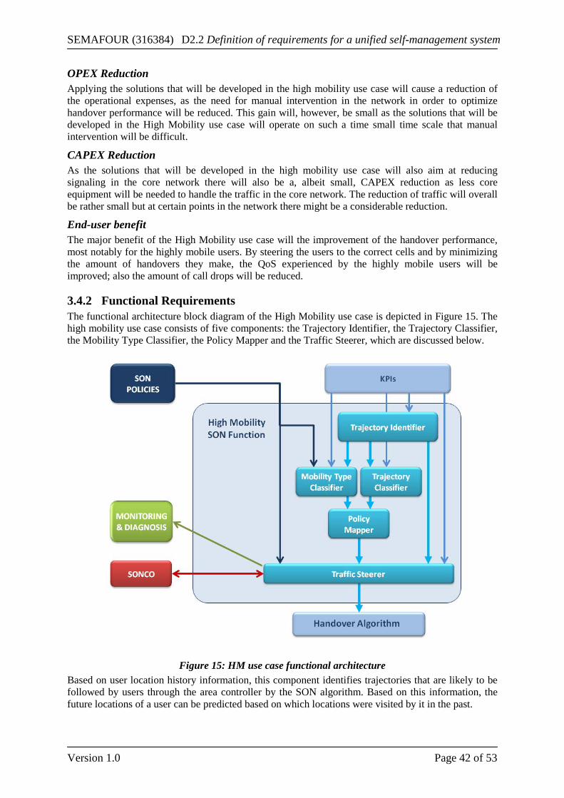
SEMAFOUR (316384) D2.2 Definition of requirements for a unified self-management system
Version 1.0 Page 42 of 53
OPEX Reduction Applying the solutions that will be developed in the high mobility use case will cause a reduction of the operational expenses, as the need for manual intervention in the network in order to optimize handover performance will be reduced. This gain will, however, be small as the solutions that will be developed in the High Mobility use case will operate on such a time small time scale that manual intervention will be difficult.
CAPEX Reduction As the solutions that will be developed in the high mobility use case will also aim at reducing signaling in the core network there will also be a, albeit small, CAPEX reduction as less core equipment will be needed to handle the traffic in the core network. The reduction of traffic will overall be rather small but at certain points in the network there might be a considerable reduction.
End-user benefit The major benefit of the High Mobility use case will the improvement of the handover performance, most notably for the highly mobile users. By steering the users to the correct cells and by minimizing the amount of handovers they make, the QoS experienced by the highly mobile users will be improved; also the amount of call drops will be reduced.
3.4.2 Functional Requirements The functional architecture block diagram of the High Mobility use case is depicted in Figure 15. The high mobility use case consists of five components: the Trajectory Identifier, the Trajectory Classifier, the Mobility Type Classifier, the Policy Mapper and the Traffic Steerer, which are discussed below.
Figure 15: HM use case functional architecture
Based on user location history information, this component identifies trajectories that are likely to be followed by users through the area controller by the SON algorithm. Based on this information, the future locations of a user can be predicted based on which locations were visited by it in the past.
SEMAFOUR (316384) D2.2 Definition of requirements for a unified self-management system
Version 1.0 Page 43 of 53
Inputs • External inputs:
o User mobility history information: the identification of the trajectories will be based on the different locations visited by the users and the times between the visiting of these locations. Different groups of users will often behave in the same fashion. For instance cyclists will most likely follow bicycle lanes and will thus pass near the same locations in a cell, their velocities will also be similar which will cause the times between visiting different locations to be the same. This information can, for instance, be derived from measurement information sent by the different users to their base stations. This information will include the signal strengths of the base stations that are the closest to the user at a certain point in time. By combining multiple measurements the approximate trajectory that is followed by a user can be reconstructed. For the sake of this use case this information will be sufficient and exact location information like GPS data is not necessary.
• Trajectory Classifier: o Ability to map users to a trajectory class: the Trajectory Identifier will identify
different trajectories followed by users and feed them to the Trajectory Classifier, which will try to map each user to a particular trajectory class. The Trajectory Classifier on its turn will feed information about how well it is able to map users to the different trajectory classes back to the Trajectory Identifier. This information can then be used to detect problems with the identified traffic classes. Firstly, no or only few users can be mapped to certain trajectory classes. This can signify that some of the identified classes are incorrect. Secondly, it might be very difficult to map certain users to one of the available trajectory classes. This can signify that there are trajectories which are followed by users that have not been identified by the Trajectory Identifier yet. Based on this information the Trajectory Identifier can remove, identify new or changed trajectories whenever there is a problem for instance when roads are closed down or new ones are constructed.
o Matched trajectories per trajectory class: the amount of trajectories that are mapped to each trajectory class. This information is used to determine if identified trajectories are (still) being used. A low value might indicate that the corresponding trajectory class is not relevant and should be removed.
Outputs • Trajectory Classifier and Traffic Steerer:
o Trajectory classes: based on the trajectories followed by different users different trajectory classes can be identified. These trajectory classes are then fed into the Trajectory Classifier, which maps each user that is controlled by the SON algorithm to a particular trajectory class and the Traffic Steerer that will decide how to steer the users on the trajectories.
3.4.2.1 Trajectory Classifier The function maps each user that is under the control of the SON algorithm to a trajectory class. Users are mapped to the trajectory class that matches the user's trajectory the best. Trajectory classes are obtained from the Trajectory Identifier and information of how well users can be mapped to trajectories is fed back to the Trajectory Identifier.
Inputs • Configuration parameters:
o Classification threshold: this threshold determines how well a certain trajectory followed by a user has to match a trajectory class in order to be considered a good match. This threshold is specified in the same distance measure that is used to check how well a certain trajectory matches a trajectory class. When the distance between a
SEMAFOUR (316384) D2.2 Definition of requirements for a unified self-management system
Version 1.0 Page 44 of 53
trajectory and the best matching trajectory class falls below this threshold for many trajectories this is an indication that there are mobility patterns that are not covered by a trajectory class and that additional trajectory classes should be defined by the Trajectory Identifier.
• External inputs: o User mobility history information: the matching of the trajectory followed by a user
on a trajectory class will be done by selecting the best trajectory class that matches a user's trajectory using a distance function. In order to do so the user's trajectories have to be known by the Trajectory Classifier.
• Trajectory Definition inputs: o Trajectory classes: like with the user mobility information also information of the
different trajectory classes has to be known.
Outputs • Policy Mapper:
o Trajectory class of each user: the trajectory class to which each user that is under the control of the SON algorithm belongs.
• Trajectory Identifier: o Ability to map users to a trajectory class: see above. o Matched trajectories per trajectory class: see above.
3.4.2.2 Mobility Type Classifier The function maps each user that is under the control of the SON algorithm to a mobility class. Examples of mobility classes are: stationary users, pedestrians, users inside a train, etc. The different mobility classes and their properties are predefined. The mobility class of a user can change over time, for instance, pedestrians might enter a pub and become stationary users, this will, however, not happen frequently.
Inputs • Policy Based SON Management:
o Mobility classes: The possible mobility types to which the Mobility Type Classifier will assign users to will be preconfigured. This allows the operator to devote special attention to certain types of users. Mobility types will be characterized by their handover behavior: frequency of handovers, distribution of handovers, etc.
• External inputs: o User mobility history information: users are classified in different mobility types
based on their mobility information. Especially the frequency and distribution of the handovers they make will be used to classify users in different mobility types.
Outputs • Policy Mapper:
o Mobility type of each user: the Mobility Type classifier will assign a mobility type to each user, which will then be used in combination with the user's trajectory class by the Policy Mapper to assign a suitable traffic steering policy to it. A user's mobility type might change over time; a pedestrian might for instance become stationary. This will, however, not happen frequently.
3.4.2.3 Policy Mapper The function maps each user to a certain traffic steering policy based on the information obtained from the Trajectory Classifier and the Mobility Type classifier. The policy determines for each user how it will be treated with regard to handovers and to where it is steered. Users with high mobility might, for
SEMAFOUR (316384) D2.2 Definition of requirements for a unified self-management system
Version 1.0 Page 45 of 53
instance, be steered towards macro cells while stationary users might for instance be steered towards a local pico cell.
Inputs • Trajectory Classifier:
o Trajectory class of each user: see above. • Mobility Type Classifier:
o Mobility type of each user: see above.
Outputs • Traffic Steerer:
o Traffic steering policy of each user: for each user the Policy Mapper will output a traffic steering policy to the Traffic Steerer. This policy determines how the users will be treated by the Traffic Steerer. A traffic steering policy might, for instance, be to steer a user to macro cells as much as possible or to keep them camped on a pico cell.
3.4.2.4 Traffic Steerer The Traffic Steerer decides when to hand over users and to which cell. The decision will be based on the user's policy that has been determined by the Policy Mapper in combination with inputs from the handover algorithm. The Traffic Steerer will set the handover parameters and give directions to the handover algorithm to steer users to the desired cell taking into account certain QoS and call drop goals.
Inputs • Policy Based SON Management:
o QoS goals: when steering traffic, the Traffic Steerer will have to make a tradeoff between QoS and call drop. The QoS goals allow the operator to set the importance of QoS for the users when making this tradeoff.
o Call drop goals: when steering traffic the Traffic Steerer will have to make a tradeoff between QoS and call drops. The call drop goals allow the operator to set the importance of call drops for the users when making this tradeoff.
• External inputs: o RSRP/RSRQ measurements: based on the RSRP/RSRQ measurements coming from
the users, the Traffic Steerer will decide if a handover is necessary and which target cells are available to make the handover to.
o User throughput: in order to take into account the QoS goals set by the operator the Traffic Steerer has to have knowledge about the QoS experienced by the users. As the throughput that is experienced by the users is a primary indicator of this QoS it will be used by the traffic steering algorithm to determine the QoS. The QoS will be measured over longer periods and will be used to improve the QoS in general over longer periods rather than the short term QoS of individual users.
o Call drop ratio: one of the primary goals of the high mobility use case is to avoid call drops as much as possible. In order to detect problems with dropped users and adjust the steering of these users appropriately, the call drop ratio has to be known. As with the user throughput this input will be measured over longer periods.
• Trajectory Identifier: o Trajectory classes: see above.
• Policy Mapper: o Traffic steering policy of each user: see above.
Outputs • External outputs to handover algorithm:
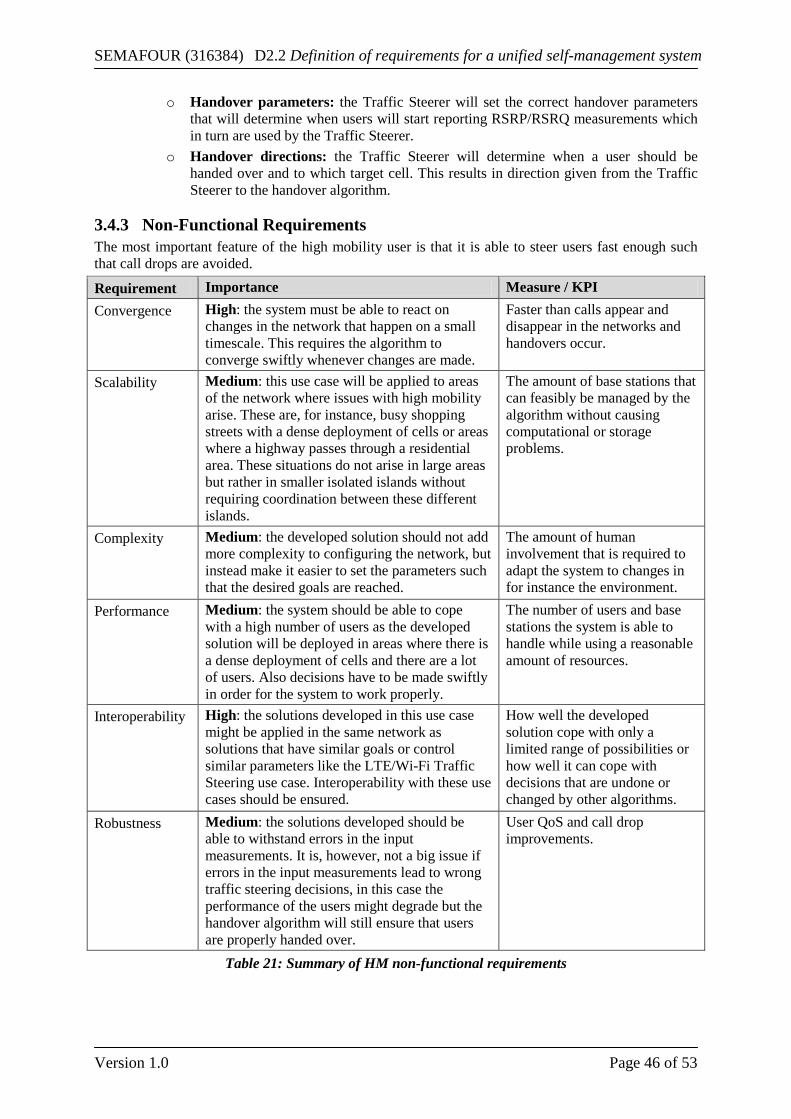
SEMAFOUR (316384) D2.2 Definition of requirements for a unified self-management system
Version 1.0 Page 46 of 53
o Handover parameters: the Traffic Steerer will set the correct handover parameters that will determine when users will start reporting RSRP/RSRQ measurements which in turn are used by the Traffic Steerer.
o Handover directions: the Traffic Steerer will determine when a user should be handed over and to which target cell. This results in direction given from the Traffic Steerer to the handover algorithm.
3.4.3 Non-Functional Requirements The most important feature of the high mobility user is that it is able to steer users fast enough such that call drops are avoided.
Requirement Importance Measure / KPI Convergence High: the system must be able to react on
changes in the network that happen on a small timescale. This requires the algorithm to converge swiftly whenever changes are made.
Faster than calls appear and disappear in the networks and handovers occur.
Scalability Medium: this use case will be applied to areas of the network where issues with high mobility arise. These are, for instance, busy shopping streets with a dense deployment of cells or areas where a highway passes through a residential area. These situations do not arise in large areas but rather in smaller isolated islands without requiring coordination between these different islands.
The amount of base stations that can feasibly be managed by the algorithm without causing computational or storage problems.
Complexity Medium: the developed solution should not add more complexity to configuring the network, but instead make it easier to set the parameters such that the desired goals are reached.
The amount of human involvement that is required to adapt the system to changes in for instance the environment.
Performance Medium: the system should be able to cope with a high number of users as the developed solution will be deployed in areas where there is a dense deployment of cells and there are a lot of users. Also decisions have to be made swiftly in order for the system to work properly.
The number of users and base stations the system is able to handle while using a reasonable amount of resources.
Interoperability High: the solutions developed in this use case might be applied in the same network as solutions that have similar goals or control similar parameters like the LTE/Wi-Fi Traffic Steering use case. Interoperability with these use cases should be ensured.
How well the developed solution cope with only a limited range of possibilities or how well it can cope with decisions that are undone or changed by other algorithms.
Robustness Medium: the solutions developed should be able to withstand errors in the input measurements. It is, however, not a big issue if errors in the input measurements lead to wrong traffic steering decisions, in this case the performance of the users might degrade but the handover algorithm will still ensure that users are properly handed over.
User QoS and call drop improvements.
Table 21: Summary of HM non-functional requirements
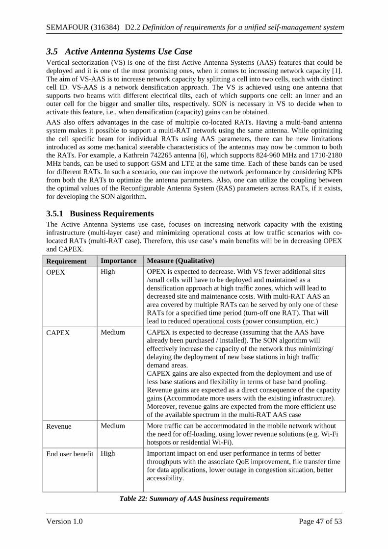
SEMAFOUR (316384) D2.2 Definition of requirements for a unified self-management system
Version 1.0 Page 47 of 53
3.5 Active Antenna Systems Use Case Vertical sectorization (VS) is one of the first Active Antenna Systems (AAS) features that could be deployed and it is one of the most promising ones, when it comes to increasing network capacity [1]. The aim of VS-AAS is to increase network capacity by splitting a cell into two cells, each with distinct cell ID. VS-AAS is a network densification approach. The VS is achieved using one antenna that supports two beams with different electrical tilts, each of which supports one cell: an inner and an outer cell for the bigger and smaller tilts, respectively. SON is necessary in VS to decide when to activate this feature, i.e., when densification (capacity) gains can be obtained. AAS also offers advantages in the case of multiple co-located RATs. Having a multi-band antenna system makes it possible to support a multi-RAT network using the same antenna. While optimizing the cell specific beam for individual RATs using AAS parameters, there can be new limitations introduced as some mechanical steerable characteristics of the antennas may now be common to both the RATs. For example, a Kathrein 742265 antenna [6], which supports 824-960 MHz and 1710-2180 MHz bands, can be used to support GSM and LTE at the same time. Each of these bands can be used for different RATs. In such a scenario, one can improve the network performance by considering KPIs from both the RATs to optimize the antenna parameters. Also, one can utilize the coupling between the optimal values of the Reconfigurable Antenna System (RAS) parameters across RATs, if it exists, for developing the SON algorithm.
3.5.1 Business Requirements The Active Antenna Systems use case, focuses on increasing network capacity with the existing infrastructure (multi-layer case) and minimizing operational costs at low traffic scenarios with co-located RATs (multi-RAT case). Therefore, this use case’s main benefits will be in decreasing OPEX and CAPEX.
Requirement Importance Measure (Qualitative) OPEX High OPEX is expected to decrease. With VS fewer additional sites
/small cells will have to be deployed and maintained as a densification approach at high traffic zones, which will lead to decreased site and maintenance costs. With multi-RAT AAS an area covered by multiple RATs can be served by only one of these RATs for a specified time period (turn-off one RAT). That will lead to reduced operational costs (power consumption, etc.)
CAPEX Medium CAPEX is expected to decrease (assuming that the AAS have already been purchased / installed). The SON algorithm will effectively increase the capacity of the network thus minimizing/ delaying the deployment of new base stations in high traffic demand areas. CAPEX gains are also expected from the deployment and use of less base stations and flexibility in terms of base band pooling. Revenue gains are expected as a direct consequence of the capacity gains (Accommodate more users with the existing infrastructure). Moreover, revenue gains are expected from the more efficient use of the available spectrum in the multi-RAT AAS case
Revenue Medium More traffic can be accommodated in the mobile network without the need for off-loading, using lower revenue solutions (e.g. Wi-Fi hotspots or residential Wi-Fi).
End user benefit High Important impact on end user performance in terms of better throughputs with the associate QoE improvement, file transfer time for data applications, lower outage in congestion situation, better accessibility.
Table 22: Summary of AAS business requirements
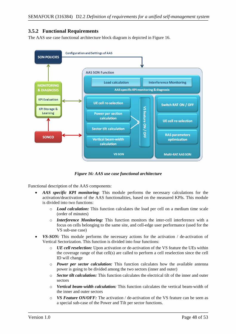
SEMAFOUR (316384) D2.2 Definition of requirements for a unified self-management system
Version 1.0 Page 48 of 53
3.5.2 Functional Requirements The AAS use case functional architecture block diagram is depicted in Figure 16.
Figure 16: AAS use case functional architecture
Functional description of the AAS components:
• AAS specific KPI monitoring: This module performs the necessary calculations for the activation/deactivation of the AAS functionalities, based on the measured KPIs. This module is divided into two functions:
o Load calculation: This function calculates the load per cell on a medium time scale (order of minutes)
o Interference Monitoring: This function monitors the inter-cell interference with a focus on cells belonging to the same site, and cell-edge user performance (used for the VS sub-use case)
• VS-SON: This module performs the necessary actions for the activation / de-activation of Vertical Sectorization. This function is divided into four functions:
o UE cell reselection: Upon activation or de-activation of the VS feature the UEs within the coverage range of that cell(s) are called to perform a cell reselection since the cell ID will change
o Power per sector calculation: This function calculates how the available antenna power is going to be divided among the two sectors (inner and outer)
o Sector tilt calculation: This function calculates the electrical tilt of the inner and outer sectors
o Vertical beam-width calculation: This function calculates the vertical beam-width of the inner and outer sectors
o VS Feature ON/OFF: The activation / de-activation of the VS feature can be seen as a special sub-case of the Power and Tilt per sector functions.
SEMAFOUR (316384) D2.2 Definition of requirements for a unified self-management system
Version 1.0 Page 49 of 53
• Multi-RAT AAS SON: This module performs the necessary actions for multi-RAT SON functionality. This module is divided into four functions:
o Switch RAT ON/OFF: This function takes the decision of activating / de-activating a RAT based on the measured KPIs and the input of other functions
o UE cell reselection: Upon activation or de-activation of a RAT, the UEs within the coverage range of that cell(s) are called to perform a cell reselection
o RAS parameters optimization: This function determines the optimum values for the RAS parameters based on measured KPIs
• KPI Evaluation: UE KPIs as well as Cell KPIs (e.g. Average Throughput, cell-edge throughput Spectrum efficiency of the cell) are evaluated on a medium time scale (order of minutes).
• KPI Storing & Learning: Cell and UE KPIs are stored on e.g. daily basis so that the system learns if and how the traffic in various areas has a repetitive behavior on e.g. daily, weekly basis (e.g. in a certain business area the traffic may be high at day and low at night time in week days)
Inputs • Measured load per cell • Traffic density & distribution • UE statistics (SINR, throughput, position) • Level of interference among cells
Outputs • UE and cell Throughput (5th, 10th and 50th percentiles) • Number of Handovers (5th, 10th and 50th percentiles) • Blocking probability • Dropped call probability
Higher level operator policies are handed down to the AAS SON function through the PBSM function, in terms of appropriate parameters. The SONCO function is responsible for the interaction between the AAS SON and the other SON functions in terms of operational conflict resolution. The inputs are used to identify time periods during which a specific geographical area or cell experience either very high load or very low load and pin point the location (hot-spots) where a large number of users are gathered. The outputs are used to determine whether the average and cell edge user performance has increased or decreased and whether the interference, the number of dropped calls or failed handovers have increased, due to the increased number of cells (case of vertical sectorization).
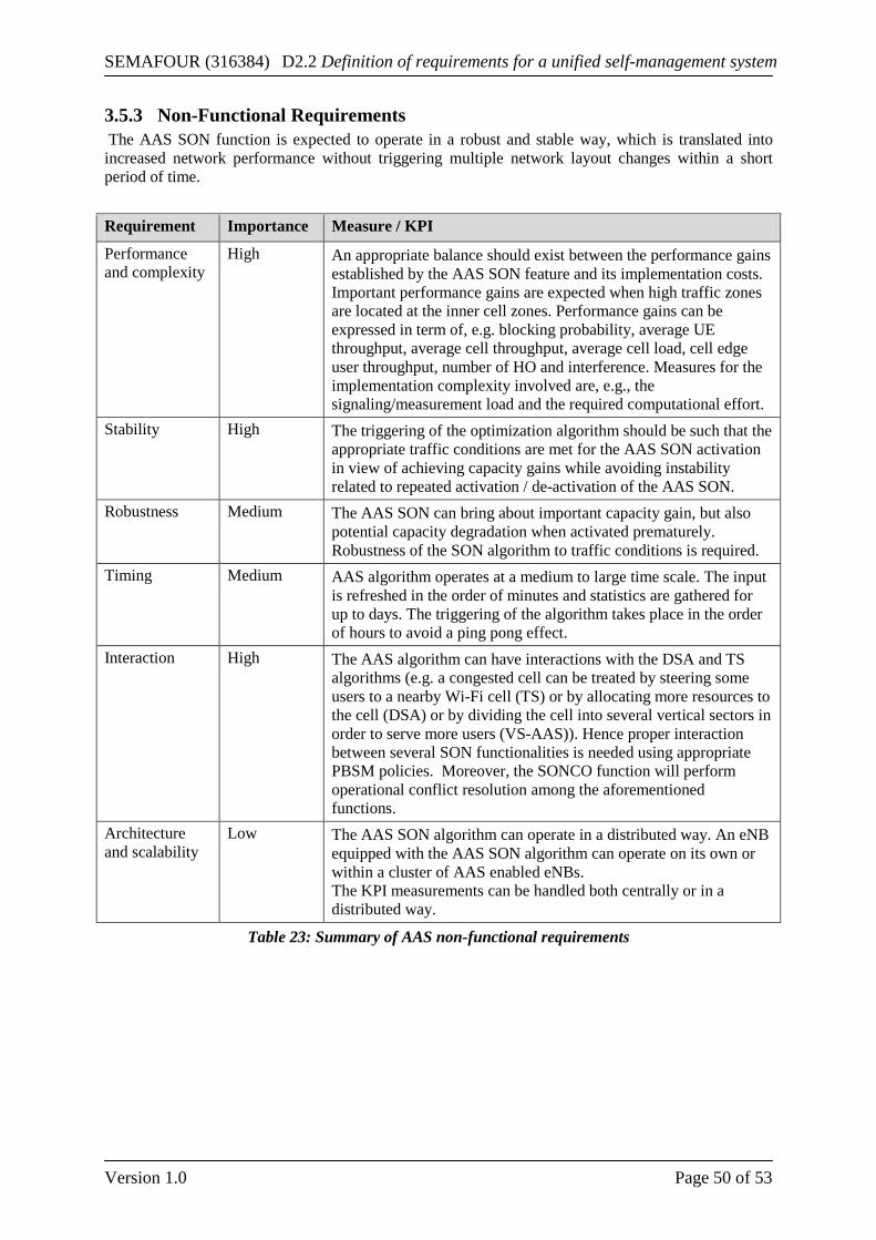
SEMAFOUR (316384) D2.2 Definition of requirements for a unified self-management system
Version 1.0 Page 50 of 53
3.5.3 Non-Functional Requirements The AAS SON function is expected to operate in a robust and stable way, which is translated into increased network performance without triggering multiple network layout changes within a short period of time. Requirement Importance Measure / KPI
Performance and complexity
High An appropriate balance should exist between the performance gains established by the AAS SON feature and its implementation costs. Important performance gains are expected when high traffic zones are located at the inner cell zones. Performance gains can be expressed in term of, e.g. blocking probability, average UE throughput, average cell throughput, average cell load, cell edge user throughput, number of HO and interference. Measures for the implementation complexity involved are, e.g., the signaling/measurement load and the required computational effort.
Stability High The triggering of the optimization algorithm should be such that the appropriate traffic conditions are met for the AAS SON activation in view of achieving capacity gains while avoiding instability related to repeated activation / de-activation of the AAS SON.
Robustness Medium The AAS SON can bring about important capacity gain, but also potential capacity degradation when activated prematurely. Robustness of the SON algorithm to traffic conditions is required.
Timing Medium AAS algorithm operates at a medium to large time scale. The input is refreshed in the order of minutes and statistics are gathered for up to days. The triggering of the algorithm takes place in the order of hours to avoid a ping pong effect.
Interaction High The AAS algorithm can have interactions with the DSA and TS algorithms (e.g. a congested cell can be treated by steering some users to a nearby Wi-Fi cell (TS) or by allocating more resources to the cell (DSA) or by dividing the cell into several vertical sectors in order to serve more users (VS-AAS)). Hence proper interaction between several SON functionalities is needed using appropriate PBSM policies. Moreover, the SONCO function will perform operational conflict resolution among the aforementioned functions.
Architecture and scalability
Low The AAS SON algorithm can operate in a distributed way. An eNB equipped with the AAS SON algorithm can operate on its own or within a cluster of AAS enabled eNBs. The KPI measurements can be handled both centrally or in a distributed way.
Table 23: Summary of AAS non-functional requirements
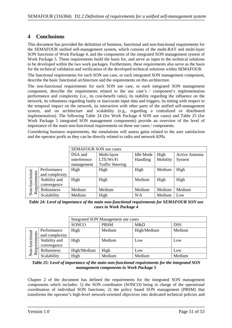
SEMAFOUR (316384) D2.2 Definition of requirements for a unified self-management system
Version 1.0 Page 51 of 53
4 Conclusions This document has provided the definition of business, functional and non-functional requirements for the SEMAFOUR unified self-management system, which consists of the multi-RAT and multi-layer SON functions of Work Package 4, and the components of the integrated SON management system of Work Package 5. These requirements build the basis for, and serve as input to the technical solutions to be developed within the two work packages. Furthermore, these requirements also serve as the basis for the technical validation and verification of the developed technical solutions within SEMAFOUR. The functional requirements for each SON use case, or each integrated SON management component, describe the basic functional architecture and the requirements on this architecture. The non-functional requirements for each SON use case, or each integrated SON management component, describe the requirements related to the use case’s / component’s implementation performance and complexity (i.e., its cost-benefit ratio), its stability regarding the influence on the network, its robustness regarding faulty or inaccurate input data and triggers, its timing with respect to the temporal impact on the network, its interaction with other parts of the unified self-management system, and on architecture and scalability (e.g., regarding a centralized or distributed implementation). The following Table 24 (for Work Package 4 SON use cases) and Table 25 (for Work Package 5 integrated SON management components) provide an overview of the level of importance of the main non-functional requirements on these use cases / components. Considering business requirements, the simulations will assess gains related to the user satisfaction and the operator profit as they can be directly related to radio and network KPIs. SEMAFOUR SON use cases DSA and
interference management
Multi-layer LTE/Wi-Fi Traffic Steering
Idle Mode Handling
High Mobility
Active Antenna System
Non
-fun
ctio
nal
Req
uire
men
ts Performance
and complexity High High High Medium High
Stability and convergence
High High Medium High High
Robustness Medium Medium Medium Medium Medium Scalability Medium High N/A Medium Low
Table 24: Level of importance of the main non-functional requirements for SEMAFOUR SON use cases in Work Package 4
Integrated SON Management use cases SONCO PBSM M&D DSS
Non
-fun
ctio
nal
Req
uire
men
ts Performance
and complexity High Medium High/Medium Medium
Stability and convergence
High Medium Low Low
Robustness High/Medium High Low Low Scalability High Medium Medium Medium
Table 25: Level of importance of the main non-functional requirements for the integrated SON management components in Work Package 5
Chapter 2 of the document has defined the requirements for the integrated SON management components which includes: 1) the SON coordinator (SONCO) being in charge of the operational coordination of individual SON functions; 2) the policy based SON management (PBSM) that transforms the operator’s high-level network-oriented objectives into dedicated technical policies and
SEMAFOUR (316384) D2.2 Definition of requirements for a unified self-management system
Version 1.0 Page 52 of 53
rules for individual SON functions; 3) the decision support system (DSS) that identifies when and where network upgrades are needed and recommend the most suitable upgrades to the network operator and 4) the monitoring and diagnosis (MD) function that provides access to, and provides an analysis of, network configuration and performance data to the three aforementioned components. Defining the functional description and the requirements for these functions is the first step towards the development of self-management solutions. This work will continue in Work Package 5, Activity 5.1. This activity will specify more detailed requirements, methods and interfaces that allow the integrated SON management to interwork with the SON functions on the one side and the operator and the OAM system on the other side. In particular, further discussions are needed to come up with a common classification of conflict types. The definition of a generic SON function model is also an important input for the policy enforcement task performed by the PBSM. The output of this activity will be consolidated in Deliverable D5.1 “Integrated SON management – basics”. Chapter 3 of the document has defined the requirements for the following Multi-RAT and Multi-layer SON use cases 1) dynamic spectrum allocation and interference management;2) multi-layer LTE/Wi-Fi traffic steering ; 3) idle mode handling; 4) high mobility and 5) active antenna systems (AAS). This work is a first step towards developing and evaluating these SON functions which is the main target of Work Package 4. A detailed definition of these SON functions, the investigation of initial directions for solutions and performance evaluation through simulations of these solutions will be the object of the Deliverable D4.1 “SON functions for multi-layer LTE and multi-RAT networks (first results)”. Finally, in a “demonstration stage” covered by Work Package 3, the developed solutions for self-management of heterogeneous radio access networks will be demonstrated. A selection of the use cases and functions described in this deliverable will be the input to these demonstration activities.
SEMAFOUR (316384) D2.2 Definition of requirements for a unified self-management system
Version 1.0 Page 53 of 53
5 References [1] SEMAFOUR Deliverable 2.1, ‘Definition of self-management use cases’, EU STREP
SEMAFOUR (INFSO-ICT-316384), February 2013
[2] Nokia Siemens Networks, ‘Smart WLAN Connectivity’, Whitepaper, February 2011, www.nokiasiemensnetworks.com
[3] Ericsson, ‘Ericsson Network Integrated Wi-Fi’, Whitepaper, September 2012, www.ericsson.com
[4] Qualcomm, ‘A 3G/LTE Wi-Fi Offload Framework: Connectivity Engine (CnE) to Manage’, Whitepaper, June 2011, www.qualcomm.com
[5] 3rd Generation Partnership Project, Technical Specification Group Radio Access Network, ‘Evolved Universal Terrestrial Radio Access Network (E-UTRAN): X2 application protocol (X2AP)’, Release 11, 3GPP TR 36.423, version 11.0.0, June 2012
[6] O. Yilmaz, S. Hamalainen, J. Hamalainen, ‘System level analysis of vertical sectorization for 3GPP LTE’, in proceedings of the 6th International Symposium on Wireless Communication Systems (ISWCS), pp. 453-457, Siena, Italy, September 7-10, 2009.
[7] Seppo Hämäläinen, Henning Sanneck, Cinzia Sartori (Editors), ‘LTE Self-organizing Networks (SON): Network Management Automation for Operational Efficiency’, John Wiley & Sons, January 2012
[8] European Commission, Seventh Framework Programme (FP7), SEMAFOUR project (INFSO-ICT-316384), Annex I – ‘Description of Work’
[9] Haijun Zhang, Wei Zheng, Xiangming Wen, Chunxiao Jiang, ‘Signalling Overhead Evaluation of HeNB Mobility Enhanced Schemes in 3GPP LTE-Advanced’, 73rd IEEE Vehicular Technology Conference (VTC Spring), Budapest, Hungary, May 15-18, 2011