Embed Size (px)
Citation preview

Mobile Crane Inspection Guidelines for OSHA Compliance Officers
This information booklet is intended to provided a generic, nonexhaustive overview of a particular standards-related topic. This publication does not itself alter or determine compliance responsibilities, which are set forth in OSHA standards themselves and the Occupational Safety and Health Act. Moreover, because interpretations and enforcement policy may change over time, for additional guidance on OSHA compliance requirements, the reader should consult current administrative interpretations and decisions by the Occupational Safety and Health Review Commission and the courts. Material contained in this publication is in the public domain and may be reproduced, fully or partially, without permission of the Federal Government. Source credit is requested by not required. This information will be made available to sensory impaired individuals upon request. Voice phone: (202) 219-8259; Telecommunications Device for the Deaf (TDD) message referral phone: 1-800-326-2577 This report was written by Anthony D. Brown
Mobile Crane Inspection Guidelines for OSHA Compliance Officers US Department of LaborRobert B. Reich, Secretary
Occupational Safety and Health AdministrationJoseph Dear, Assistant Secretary
Office of Construction and EngineeringCharles G. Culver, Director
June 1994
TABLE OF CONTENTS← ACKNOWLEDGEMENTS ← ABSTRACT ← EXECUTIVE SUMMARY ← 1.0 INTRODUCTION ← 2.0 MOBILE CRANES
← 2.1 Lifting Principles ← 2.2 Operational Considerations
← 3.0 REQUIREMENTS FOR MOBILE CRANES ← 3.1 OSHA Construction Requirements ← 3.2 ASME/ANSI and PCSA Requirements
← 4.0 INSPECTING A MOBILE CRANE ← 4.1 Preinspection ← 4.2 Crane Setup ← 4.3 Electrical Hazards ← 4.4 Load Charts ← 4.5 Safe Operating Precautions ← 4.6 Inspection Types ← 4.7 Starting the Inspection ← 4.8 Specific Inspection Items and References
← APPENDIX A - GENERAL TERMS AND DEFINITIONS ← APPENDIX B - GENERAL LOAD CHARTS AND OPERATIONAL CONSIDERATIONS ← APPENDIX C - BASIC CRANE COMPONENTS
ACKNOWLEDGEMENTS
Staff from the OSHA National Office provided assistance in preparing this report. Mike

Marshall and Chuck Hardesty, Office of Construction and Engineering; Ted Twardowski, Office of Construction and Civil Engineering Safety Standards provided initial information and reviewed comments; James Calvert, Engineer in Training, typed and edited the report, and developed charts, tables, and graphics for the report.
William Smith, Director of Safety and Health, International Union of Operating Engineers; Richard Giacin, Administrator, Local 478, International Union of Operating Engineers, Meridan, CT.; and Scott Buck, Safety Director, Local 150, International Union of Operating Engineers, Plainfield, IL, contributed technical assistance, photographs and review comments throughout the project.
Individual members of the ASME/ANSI B30 Committee, provided technical information, materials, pictures and continual review comments. Those members include:
Paul Zorich, U.S. Department of the Navy and Chair of the B30 Committee; Theodore A. Christensen, Liberty Mutual Insurance Co; Bradley D. Closson, President, North American Crane Bureau, West; James J. Headley, President, Crane Institute of America, Inc.; Carson L. Huneycutt, Equipment Operations Manager, J.A. Jones, Inc.; Edward E. Rudy, U.S. Department of the Army; and Robert C. Wild, U.S. Army Corps of Engineers.
A special thanks to Leon (Skip) S. Johnson, American Equipment Company for his technical assistance and review comments and in acquiring photographs and video footage of a simulated crane inspection on a Flour Daniels, Inc., construction project in LA.
Steve Peterson, Training Manager, American Crane Corporation, Dennis Eckstine, Director, Product Safety, Grove Corp., and Dan Wolff, Manager for Engineering, National Crane Corp. for review comments and technical assistance.
Tom Kollins, Vice President, Specialized Carriers and Riggers Association, SC&RA, through the membership, provided assistance and initial evaluation of contents and format.
ABSTRACT
This document provides background information about lifting principles and serves as a guideline for inspecting mobile construction cranes. The relationship of many components of cranes and their inter-dependence in lifting operations, OSHA requirements for proper maintenance schedules, and safe crane operations will be discussed in this document.
This document contains a listing and description of major components or operations to be considered or examined when inspecting lifting equipment. Two types of commonly used cranes, a crawler lattice boom crane and a hydraulic rough terrain crane, were selected as examples in developing these guidelines. Descriptive text and photographs illustrate 18 inspection items critical to most crane inspections.
EXECUTIVE SUMMARY
OSHA compliance officers, project safety and health managers, and insurance inspectors are often required to inspect construction cranes. Inspections normally include lengthy checklists that identify mechanical components and maintenance schedules without adequate descriptions or explanations, pertinent to the relationship between these components and the crane's overall function. Although some crane inspection checklist items are self-explanatory, it must be recognized that due to increasing applications of developing technology in the design and manufacture of cranes, OSHA compliance officers need a better understanding of crane operations and their basic lifting principles, and to keep abreast of related developments in today's construction industry.
2

Since cranes affect a large segment of work at any construction site, crane inspections by the compliance officer and project safety manager must include a survey of the entire operation questions on how the crane will be operating and how other crafts will be affected by working with and around the crane.
Observing crane operations prior to an inspection, or asking questions about how it will or has been operating, can indicate possible problem areas that may need a closer review during the inspection process.
This document provides an overview and background information on lifting principles of mobile cranes for OSHA inspectors. Also discussed is the relationship between various components of mobile cranes to their lifting capacity and the manufacturers' requirements for conducting proper maintenance schedules are also discussed.
Typical Construction Site Load Block Lowered for Inspection
1.0 IntroductionOver the past few decades, there has been a significant increase in the cost of cranes due in part to improved engineering design and specific job site requirements.
Today, manufacturers design and build stronger and lighter cranes in response to specific industry needs. Speed, utility, capacity, and reach (radius) have been improved to the point that the crane has become an indispensable workhorse for construction. Therefore, a more thorough understanding of cranes, their capabilities and limitations is critically important for everyone involved in construction today. The crane can perform safely and economically when operated within the design
3

parameters set by the manufacturer. Modern Ringer Crane 500-Ton CapacityDue to significant advances in lifting technology, crane operators, site supervisors, safety professionals, and OSHA compliance officers need to keep abreast of modern crane technology and changes in operating procedures to help them recognize problems before potentially unsafe conditions lead to accidents that result in injuries and/or fatalities, as well as equipment damages.With these factors in mind, the need for a better understanding of crane operations and the implementation of appropriate maintenance schedules is evident in preventing accidents.A recent study by Don Dickie, a recognized crane authority with the Construction Safety Association of Ontario, indicates that although mechanical failures represent only 11% of the causes of crane accidents, they usually result in the major accidents involving injuries, fatalities, substantial material costs, and usually spectacular media coverage. Studies and analyses of crane accidents involving mechanical failure show they are frequently due to a lack of preventive maintenance or adequate training and/or experience on the part of the personnel involved. It is important that not only crane operators but also other personnel working with cranes receive training in crane operations. Cranes and associated rigging equipment must be inspected regularly to identify any existing or potentially unsafe conditions. In addition, preventive maintenance must be performed as required by the crane manufacturer and/or the supplier to ensure safe crane operation. The inspections performed by OSHA compliance officers and/or other safety professionals also can play an important role by identifying hazards as well as safe crane operations.
This report addresses major issues related to the crane itself and provide some basic information on crane capacities and inspection criteria for OSHA compliance officers. Since it would be difficult for a single report to fully address all types of cranes available in today's market, two types of cranes typically found on construction sites are discussed in this report. Some of the issues encountered during inspections cover the following three areas:
← Basic Crane Operations – Lifting principles/mechanics and some operational criteria.
← Typical Crane inspection Checklist – Listing of critical items and components recommended for periodic inspection.
← Regulations – Federal OSHA regulations and applicable ASME/ANSI and PCSA standards.
This report also contains general guidelines for crane inspections, as well as some suggested operational considerations and inspection items recognized by a number of construction companies.
Cranes are designed for both general use and for specific purposes. Similar to the vast automobile industry, crane manufacturers produce similar models or types of cranes for the same purpose, often with different sizes of the same model of crane. Each type, model, or size of crane manufactured, may have different operating controls and require specialized operator training, individualized inspection criteria, and different preventive maintenance schedules.
Two commonly used cranes, a hydraulic rough terrain crane and a crawler lattice boom friction crane, are shown as examples for developing this document. There are several significant differences between these two cranes, primarily in boom hoist and load line controls. The somewhat smooth operation of the boom control adjustments on the hydraulic cranes may suggest falsely to the novice operator or inspector that it
4

is a simple crane to operate. On the other hand, the lattice boom friction cranes' movement in its boom, or its adjustment in load position tend to be a little jerky requiring more skill and experience to operate smoothly. Another clear difference between the two types of cranes is their load charts. Due to the fixed boom length, the lattice boom friction crane has a somewhat simplified load chart. This requires extensive motion control and an anticipation of boom movement to accurately lift or place loads. Conversely, the hydraulic crane's load charts are more extensive or complicated due to the variations in boom length thus requiring more training in the multiple charts available. The differences between these two types of cranes are significant enough to require specific training on each type of crane. Crane operators cannot be expected to be totally knowledgeable and proficient in the operation of the many diverse types of cranes available today. They cannot be expected to move from one type of crane to another without adequate education and training on the specifics of each piece of equipment.
Variety of Crawler Rough Terrain (R/T) Crane
Mobile Crawler Crane Operator's View Lattice Boom2.0 Mobile Cranes2.1 Lifting Principles There are four basic lifting principles that govern a crane's mobility and safety during lifting operations:
1. Center of Gravity The center of gravity of any object is the point in the object where its weight can be assumed to be concentrated or, stated in another way, it is the point in the object around which its weight is evenly distributed. The location of the center of gravity of a mobile crane depends primarily on the weight and location of its heaviest components (boom, carrier, upperworks and counterweight).
2. Leverage Cranes use the principle of leverage to lift loads. Rotation of the upperworks (cab, boom, counterweight, load) changes the location of the crane's center of gravity, its leverage point or fulcrum.
5

As the upperworks rotates, the leverage of a mobile crane fluctuates. This rotation causes the crane's center of gravity to change and causes the distance between the crane's center of gravity and its tipping axis to also change. Stability can be effected by the fluctuating leverage the crane exerts on the load as it swings. The crane's rated capacity is therefore altered in the load chart to compensate for those changes in leverage.
Provided the ground is capable of supporting the load, a crane can be made more stable by moving the tipping axis further away from its center of gravity. The extra stability gained by moving the tipping axis can then be used to carry larger/heavier loads.
INCREASED STABILITY = MORE LOAD 3. Stability Is the relationship of the load weight, angle of the boom and its radius
(distance from the cranes center of rotation to the center of load) to the center of gravity of the load. The stability of a crane could also be effected by the support on which the crane is resting. A crane's load rating is generally developed for operations under ideal conditions, i.e., a level firm surface. Unlevel surfaces or soft ground therefore must be avoided. In areas where soft ground poses a support problem for stability, mats and or blocking should be used to distribute a crane's load and maintain a level stable condition.
In addition to overturning (stability failure), cranes can fail structurally if overloaded enough. Structural failure may occur before a stability failure. In other words, a mobile crane's structure may fail long before it tips. As loads are added beyond its rated capacity, a crane may fail structurally before there is any sign of tipping. Structural failure is not limited to total fracture; it includes all permanent damage such as overstressing, bending and twisting of any of the components. When a crane is overstressed, the damage may not be apparent. Nevertheless, a structural failure has occurred and overstressed components are then subject to catastrophic failure at some future time.
4. Structural Integrity The crane's main frame, crawler track and/or outrigger supports, boom sections, and attachments are all considered part of the structural integrity of lifting. in addition, all wire ropes, including stationary supports or attachment points, help determine lifting capacity and are part of the overall structural integrity of a crane's lifting capacity. The following elements may also affect structural integrity:
← The load chart capacity in relationship to stability; ← The boom angle limitations which affect stability and capacity; and ← The knowledge of the length of boom and radius in determining
capacity.
Stability failures are foreseeable, but in structural failure it is almost impossible to predict what component will fail at any given time. No matter what the cause, if the crane is overloaded, structural failure can occur.
2.2 Operational Considerations
Cranes are carefully designed, tested, and manufactured for safe operation. When used properly they can provide safe reliable service to lift or move loads. Because cranes have the ability to lift heavy loads to great heights, they also have an increased potential for catastrophic accidents if safe operating practices are not followed.
Crane operators and personnel working with cranes need to be knowledgeable of basic crane capacities, limitations, and specific job site restrictions, such as location of overhead electric power lines, unstable soil, or high wind conditions. Personnel working around crane operations also need to be aware of hoisting activities or any job restrictions imposed by crane operations, and ensure job site coordination of cranes. Crane inspectors therefore should become aware of these issues and, prior to starting an inspection, take time to observe the overall crane operations with respect to load capacity, site coordination, and any job site restrictions in effect.
6

Rough Terrain (R/T) 45-Ton Crane 150-Ton Crawler Lattice Boom(Hydraulic Crane) Friction Crane
3.0 Requirements For Mobile Cranes3.1 OSHA Construction RequirementsA review of the OSHA crane standards provide a basis for a crane inspection. Construction crane standards requirements are found in Subpart N, 29 CFR 1926.550. Some key requirements state that: (1) The employer shall comply with the manufacturer's specifications and limitations applicable to the operation of any and all cranes and derricks. Where manufacturer's specifications are not available, the limitations assigned to the equipment shall be based on the determinations of a qualified engineer competent in this field and such determinations will be appropriately documented and recorded. Attachments used with cranes shall not exceed the capacity, rating, or scope recommended by the manufacturer. (2) Rated load capacities, and recommended operating speeds, special hazard warnings, or instruction, shall be conspicuously posted on all equipment. Instructions or warnings shall be visible to the operator while he is at his control station. (5) The employer shall designate a competent person who shall inspect all machinery and equipment prior to each use, and during use, to make sure it is in safe operating condition. Any deficiencies shall be repaired, or defective parts replaced, before continued use. (6) A thorough, annual inspection of the hoisting machinery shall be made by a
7

competent person, or by a government or private agency recognized by the U.S. Department of Labor. The employer shall maintain a record of the dates and results of inspections for each hoisting machine and piece of equipment. (15) Except where electrical distribution and transmission lines have been de-energized and visibly grounded at point of work or where insulating barriers, not a part of or an attachment to the equipment or machinery, have been erected to prevent physical contact with the lines, equipment or machines shall be operated approximate to power lines only in accordance with the following: (i) For lines rated 50 kV or below, minimum clearance between the lines and any part of the crane or load shall be 10 feet; (ii) For lines rated over 50 kV, minimum clearance between the lines and any part of the crane or load shall be 10 feet plus 0.4 inch for each 1 kV over 50 kV, or twice the length of the line insulator, but never less than 10 feet; (iv) A person shall be designated to observe clearance of the equipment and give timely warning for all operations, where it is difficult for the operator to maintain the desired clearance by visual means; (vi) Any overhead wire shall be considered to be an energized line unless and until the person owning such line or the electrical utility authorities indicate that it is not an energized line and it has been visibly grounded. (16) No modifications or additions which effect the capacity or safe operation of the equipment shall be made by the employer without the manufacturer's written approval. In no case shall the original safety factor of the equipment be reduced. To supplement the OSHA standards for Cranes and Derricks, references are made to applicable ASME/ANSI and PCSA standards. The ASME/ANSI "B30" series of standards address: "Cranes", "Cableways", "Derricks", "Hoists", "Hooks", "Jacks" and "Slings". For the purpose of this document ASME/ANSI B30.5, "Mobile and Locomotive Cranes" will be the reference document for the crane inspection criteria.
References also are made to the Power Crane Shovel Association (PCSA), Standard No. 2, "Mobile it Hydraulic Crane Standards."
3.2 ASME/ANSI and PCSA Requirements
ASME/ANSI B30.5 PSCA Standard No. 2
8

4.0 Inspecting A Mobile CraneSince cranes impact such a large segment of work going on at any job site, crane inspections (to the OSHA Compliance Officer and Project Safety Managers) must include a survey, or walk around, of the entire operation that questions how the crane will be operating and how other crafts will be effected by working with and around the crane? Observation of crane operations prior to an inspection, or simply asking how cranes have or will be used, can indicate possible problem areas that may need a closer review during the inspection process.
4.1 Preinspection
Before the actual inspection, some general information about the crane operator's qualifications and the crane's certifications should be gathered, such as:Operator Qualifications Observe the operator in action and when the opportunity permits ask a few question concerning the cranes capacity and restrictions imposed, either due to activity involved in or functional limitations.
Crane Records Ask for inspection and maintenance records and verify that the appropriate operator's manual and load charts are available for that particular crane in use. 4.2 Crane Setup
In your initial survey of crane operations, look for crane stability, physical obstructions to movement or operation, and proximity of electrical power lines, as well as the following:
A. Leveling Has the crane operator set the crane up level and in a position for safe rotation and operation?
B. Outriggers Are the outriggers, where applicable, extended and being used in accordance with manufacturer's recommendations?
C. Stability The relationship of the load weight, angle of boom, and its radius (the distance from the cranes center of rotation to the center of load) to the center of gravity of the load. Also, the condition of crane loading where the load moment acting to overturn the crane is less than the moment of the crane available to resist overturning.
D. Structural Integrity The crane's main frame, crawler, track and outrigger supports, boom sections, and attachments are all considered part of structural components of lifting. In addition, all wire ropes, including stationary supports, help determine lifting capacity and are part of the structural elements of crane operations.
4.3 Electrical Hazards
Working around or near electrical power lines is one of the most dangerous practices for crane operations. The OSHA requirements limit crane operations to a minimum clearance of 10 feet.
Cranes should not be used to handle materials or loads stored under electric power lines. In addition, operation of mobile cranes near de-energized electric power lines is not recommended until the following steps have been taken:
← The power company or owner of the power line has deenergized the lines. ← The lines are visibly grounded and appropriately marked at jobsite. ← Durable warning signs are installed at the operator's station and on the outside
of the crane identifying the clearance requirements between the crane/load and electrical power lines.
← A qualified representative of the power company or owner of the electrical power line are on the job site to verify that the power lines have been de-energized or properly grounded.
4.4 Load Charts
9

Load Charts are the principle set of instructions and requirements for boom configurations and parts of line which establish crane capacity for safe crane operations*.
← Availability The crane operator must have in his/her possession the appropriate load charts related to the crane in use and for the loads being lifted.
← Correct Use The crane operator must show adequate understanding and proficient use of the load charts as related to the equipment in use and the loads being lifted.
4.5 Safe Operating Precautions
As stated above, cranes are carefully designed, tested, and manufactured for safe operations. When used properly they can provide safe reliable service to lift or move loads. Because cranes have the ability to lift heavy loads to great heights, they also have an increased potential for catastrophic accidents if safe. operating practices are not followed.
Accidents can be avoided by careful job planning. The person in charge must have a clear understanding of the work to be performed and consider all potential dangers at the job site. A safety plan must be developed for the job and must be explained to all personnel involved in the lift.
Before operations begin for the day, a walkaround inspection needs to be conducted to ensure that the machine is in proper working condition. Only qualified and properly designated people shall operate the crane. Regular inspections are important, they provide a means of detecting potential hazards or conditions that could contribute to a sequence of events leading to an accident. Safe, reliable, and the economic operation of lifting equipment, cannot be ensured without regular safety inspections and thorough preventive maintenance programs. A thorough inspection program can forecast maintenance needs or potential equipment failures or malfunctions. The lack of such a program could result in serious deterioration of the equipment which might lead to excessive replacement, or repair charges, as well as an increased potential for accidents.*See General Load Charts and Operational Considerations, Appendix B.
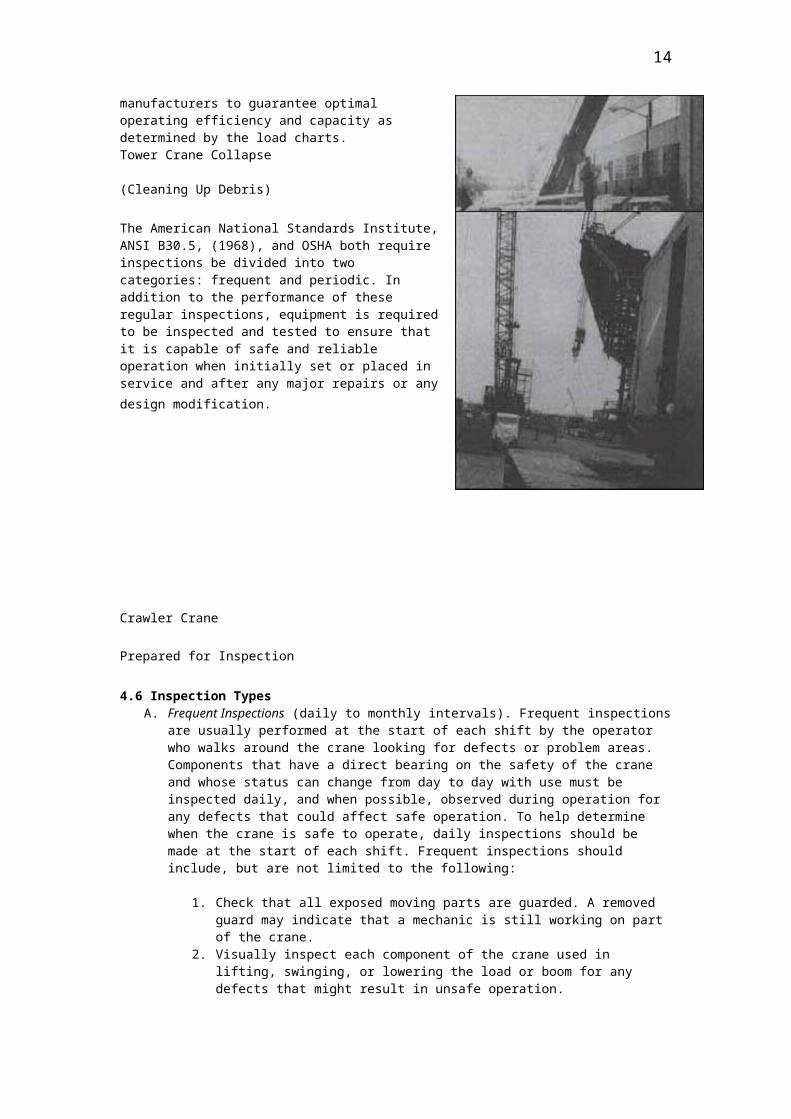
Due to the wide variation of conditions under which a crane may operate, it is impossible for the manufacturer to determine inspection intervals appropriate for every situation. Inspection intervals recommended in manufacturer's publications represent minimum intervals for average operating conditions. More frequent inspection intervals should be required if use and site conditions are severe and warrant it. Inspections are also designed as maintenance checks and/or as a verification that proper repairs or modifications of equipment have been completed which, if not checked could affect capacities as well as personnel safety. Since the initial load rating for cranes was determined and set under ideal conditions, inspections are required by manufacturers to guarantee optimal operating efficiency and capacity as determined by the load charts. Tower Crane Collapse (Cleaning Up Debris)
The American National Standards Institute, ANSI B30.5, (1968), and OSHA both require inspections
10

be divided into two categories: frequent and periodic. In addition to the performance of these regular inspections, equipment is required to be inspected and tested to ensure that it is capable of safe and reliable operation when initially set or placed in service and after any major repairs or any design modification.
Crawler Crane Prepared for Inspection
4.6 Inspection TypesA. Frequent Inspections (daily to monthly intervals). Frequent inspections are
usually performed at the start of each shift by the operator who walks around the crane looking for defects or problem areas. Components that have a direct bearing on the safety of the crane and whose status can change from day to day with use must be inspected daily, and when possible, observed during operation for any defects that could affect safe operation. To help determine when the crane is safe to operate, daily inspections should be made at the start of each shift. Frequent inspections should include, but are not limited to the following:
1. Check that all exposed moving parts are guarded. A removed guard may indicate that a mechanic is still working on part of the crane.
2. Visually inspect each component of the crane used in lifting, swinging, or lowering the load or boom for any defects that might result in unsafe operation.
3. Inspect all wire rope (including standing ropes), sheaves, drums rigging, hardware, and attachments. Remember, any hook that is deformed or cracked must be removed from service. Hooks with cracks, excessive throat openings of 15%, or hook twists of 10 degrees or more, must be removed from service.
4. Check for freedom of rotation of all swivels. 5. Visually inspect the boom and jib for straightness and any evidence of
physical damage, such as cracking, bending, or any other deformation of the welds. Look for corrosion under any attachments that are connected to the chords and lacing. Watch carefully for cracking or flaking of paint. This may indicate fatigue of the metal which often precedes a failure. On lattice booms, look for bent lacing. If they are kinked or bent, the main chord can lose substantial support in that area. When lacing is bent, the ends also tend to draw together which pulls the main chords out of shape. This precaution is especially important on tubular booms where every component must be straight and free from any dents. Do not attempt to straighten these members by hammering or heating them and drawing them out. They must be cut out and replaced with lacing to the manufacturer's specifications, procedures, and approval.
6. Inspect tires for cuts, tears, breaks, and proper inflation. 7. Visually inspect the crane for fluid leaks, both air and hydraulic. 8. Visually check that the crane is properly lubricated. The fuel,
lubricating oil, coolant and hydraulic oil reservoirs should be filled to proper levels.
9. Check that the crane is equipped with a fully charged fire extinguisher and that the operator knows how to use it.
10. Check all functional operating mechanisms such as: sheaves, drums, brakes, locking mechanisms, hooks, the boom, jib, hook rollers
11

brackets, outrigger components, limit switches, safety devices, hydraulic cylinders, instruments, and lights.
11. Check the turntable connections for weld cracks and loose or missing bolts. If they are loose, there is a good chance that they have been stretched.
12. When checking the outriggers be sure that neither the beams nor the cylinders are distorted. Check that the welds are not cracked and that both the beams and cylinders extend and retract smoothly and hold the load. Check the condition of the floats, and check that they are securely attached.
13. Inspect and test all brakes and clutches for proper adjustment and operation.
14. Always inspect boom hoist lockout and other operator aids, such as anti-two-block devices (ATB) and load moment indicators (LMI), for proper operation and calibration.
15. While the engine is running, check all gauges and warning lights for proper readings and operate all controls to see that they are functioning properly.
16. Check for any broken or cracked glass that may affect the view of the operator.
B. Periodic Inspections (1 to 12 month intervals). The periodic inspection procedure is intended to determine the need for repair or replacement of components to keep the machine in proper operating condition. It includes those items listed for daily inspections as well as, but not limited to, structural defects, excessive wear, and hydraulic or air leaks.
Inspection records of the inspected crane shall be maintained monthly on critical items in use, such as brakes, crane hooks, and ropes. These inspection records should include, the date of inspection, the signature of the person who performed the inspection, and the serial number, or other identifier. This inspection record should be kept readily available for review. The manufacturer's maintenance and inspection records, forms/checklist, or equivalent should be used.
1. Inspect the entire crane for structural damage. Be careful to check for distortion or cracks in main frame, outrigger assemblies, and structural attachments of the upperworks to the carrier.
2. Inspect all welded connections for cracks. Inspect the main chords and lacings and other structural items for paint flaking and cracking which may indicate potential failure, as well as for dents, bends, abrasions, and corrosion. Check hydraulic booms for bending, side sway, or droop.
3. Check for deformed, cracked, or corroded members in the load/stress bearing structure. Magnetic particle or other suitable crack detecting inspection should be performed at least once each year by an inspection agency retained by the owner. Inspection reports should be requested and retained in the crane file.
4. Inspect cracked or worn sheaves and drums. 5. Inspect for worn, cracked, or distorted parts such as: pins, bearings, shafts,
gears, rollers, locking devices, hook roller brackets, removable outrigger attachments lugs, and welds.
6. Inspect for excessive wear on brake and clutch system parts, linings, pawls, and ratchets.
7. Inspect all indicators, including load and boom angle indicators, for proper operation and calibration.
8. Inspect all power plants for proper operation. 9. Inspect for excessive wear on drive sprockets and/or chain stretch. 10. Inspect for correct action of steering, braking, and locking devices. 11. Check that the counterweight is secure. 12. Check that the identification number is permanently and legibly marked on
jibs, blocks, equalizer beams, and all other accessories. 13. Inspect all hydraulic and pneumatic hoses, fittings, and tubing. Any
deterioration of any system component should cause the inspector to question whether further use would constitute a safety hazard. Conditions, such as the following, require replacement of the part in question:
12

a. Any evidence of oil or air leaks on the surfaces of flexible hoses or at the point at which the hose in question joins the metal end couplings.
b. Any abnormal deformation of the outer covering of hydraulic hose, including any enlargement, local or otherwise.
c. Any leakage at connections which cannot be eliminated by normal tightening.
d. Any evidence of abrasive wear that could have reduced the pressure retaining capabilities of the hose or tube effected. The cause of the rubbing or abrasion must be immediately eliminated.
4.7 Starting the Inspection
Since most crane inspections begin with a general walkaround and observation of the overall crane set up and operation, followed by a specific inspection of items or components, the following guidelines are presented in that order. The first section addresses the general items and operational considerations when inspecting any type of crane, followed by the specific inspection items for two specific types of cranes; Grove Rough Terrain 45 Ton (hydraulic) and Manitowoc 4100 150 Ton Crawler (lattice boom friction) cranes.
In general, the following should be considered when inspecting any crane:1. Request for and review all inspection and maintenance documents for the
crane being inspected, including the crane manufacturer's inspection and maintenance requirements.
2. Conduct a walkaround inspection, paying particular attention to mechanical systems leaks or damage (oil, hydraulic, air) and structural deficiencies.
3. Look at crane cab for properly marked controls, damaged instruments and for properly displayed and legible load charts.
4. Ask the operator, ground crew (riggers), and/or supervisors appropriate questions on load charts, rigging and load weight determinations, and capacities.
5. Request the operator to raise and lower the boom/load line, where practical, and inspect, from the cab position, the running line or rope of the main hoist drum and secondary line or jib line. Check brake action and its ability to stop.
6. If practical, request the operator to lower boom to look at the condition of booms sections, lacing, lifting components, anti-two-block devices, jib back stops, and the condition of the hook.
7. Check crane set up and stability of outriggers on hydraulics and/or the effectiveness of cribbing on crawlers. if possible, request that the crane be rotated to check all clearances and overall stability.
4.8 Specific Inspection Items and References
The following table identifies the specific inspection items for cranes as well as a brief description and purpose to help the inspector to have a better understanding of what and why the item is being inspected.
Table 4.8A –Inspection Items and Description ITEM DESCRIPTION / PURPOSE
(1) Manufacturer's operating and Maintenance Manuals
Manufacturer's operating and maintenance manuals shall accompany all mobile hoisting equipment. These manuals set forth specific inspection, operation and maintenance criteria for each mobile crane and lifting capacity.
(2) Guarding All exposed moving parts such as gears, chains, reciprocating or rotating parts are guarded or isolated.
13
(3) Swing Clearance Protection Materials for guarding rear swing area.(4) High-Voltage Warning Sign High-voltage warning signs displaying
restrictions and requirements should be installed at the operator's station and at strategic locations on the crane.
(5) Boom Stops Shock absorbing or hydraulic type boom stops are installed in a manner to resist boom overturning.
(6) Jib Boom Stops Jib stops are restraints to resist overturning.(7) Boom Angle Indicator A boom angle indicator readable for the
operator station is installed accurately to indicate boom angle.
(8) Boom Hoist Disconnect, Automatic Boom Hoist Shutoff
A boom hoist disconnect safety shutoff or hydraulic relief automatically stops the boom hoist when the boom reaches a predetermined high angle.
(9) Two-Blocking Device Cranes with telescoping booms should be equipped with a two-blocking damage prevention feature that has been tested on-site in accordance with manufacturers requirements. All cranes hydraulic and fixed boom used to hoist personnel must be equipped with two-blocking devices on all hoistlines intended to be used in the operation. The anti-two blocking device has automatic capabilities for controlling functions that may cause a two-blocking condition.
(10) Power Controlled Lowering Cranes for use to hoist personnel must be equipped for power controlled lowering operation on all hoistlines. Check clutch, chains, and sprockets for wear.
(11) Leveling Indicating Device A device or procedure for leveling the crane must be provided.
(12) Sheaves Sheave grooves shall be smooth and free from surface defects, cracks, or worn places that could cause rope damage. Flanges must not be broken, cracked, or chipped. The bottom of the sheave groove must form a close fitting saddle for the rope being used. Lower load blocks must be equipped with close fitting guards. Almost every wire rope installation has one or more sheaves – ranging from traveling blocks with complicated reeving patterns to equalizing sheaves where only minimum rope movement is noticed.
(13) Main Hoist and Auxiliary Drums System
Drum crushing is a rope condition sometimes observed which indicates deterioration of the rope. Spooling is that characteristic of a rope which affects how it wraps onto and off a drum. Spoiling is affected by the care and skill with which the first larger of wraps is applied on the drum. Manufacturer's criteria during inspection usually specify:
← Minimum number of wraps to remain on the drum.
← Condition of drum grooves
14

← Condition of flanges at the end of drum.
← Rope end attachment. ← Spooling characteristics of rope.
← Rope condition. (14) Main Boom, Jib Boom, Boom Extension
Boom jibs, or extensions, must not be cracked or corroded. Bolts and rivets must be tight. Certification that repaired boom members meet manufacturers original design standard shall be documented. Non-certified repaired members shall not be used until recertified.
(15) Load Hooks and Hook Blocks Hooks and blocks must be permanently labeled with rated capacity. Hooks and blocks are counterweighted to the weight of the overhaul line from highest hook position. Hooks must not have cracks or throat openings more than 15% of normal or twisted off center more than 10o from the longitudinal axis. All hooks used to hoist personnel must be equipped with effective positive safety catches especially on hydraulic cranes.
(16) Hydraulic Hoses Fittings and Tubing
Flexible hoses must be sound and show no signs of leaking at the surface or its junction with the metal and couplings. Hoses must not show blistering or abnormal deformation to the outer covering and no leaks at threaded or clamped joints that cannot be eliminated by normal tightening or recommended procedures. There should be no evidence of excessive abrasion or scrubbing on the outer surfaces of hoses, rigid tubing, or hydraulic fittings.
(17) Outriggers Outrigger number, locations, types and type of control are in accordance with manufacturer's specifications. Outriggers are designed and operated to relieve all weight from wheels or tracks within the boundaries of the outriggers. If not, the manufacturer's specifications and operating procedures must be clearly defined. Outriggers must be visible to the operator or a signal person during extension or setting.
(18) Load Rating Chart A durable rating chart(s) with legible letters and figures must be attached to the crane in a location accessible to the operator while at the controls. The rating charts shall contain the following:
← A full and complete range of manufacturer's crane loading ratings at all stated operating radii.
← Optional equipment on the crane such as outriggers and extra counterweight which effect ratings.
← A work area chart for which capacities are listed in the load rating chart, i.e. over side, over rear, over front.
← Weights of auxiliary equipment, i.e.
15

load block, jibs, boom extensions. ← A clearly distinguishable list of ratings
based on structural, hydraulic or other factors rather than stability.
← A list of no-load work areas.
← A description of hoistline reeving requirements on the chart or in operator's manual.
(19) Wire Rope Main hoist and auxiliary wire rope inspection should include examining for
← Broken wires. ← Excess wear.
← External damage from crushing, kinking, cutting or corrosion.
(20) Cab Contains all crane function controls in addition to mechanical boom angle indicators, electric wipers, dash lights, warning lights and buzzers, fire extinguishers, seat belts, horn, and clear unbroken glass.
(21) Braking Systems Truck cranes and self-propelled cranes mounted on rubber-tired chassis or frames must be equipped with a service brake system, secondary stopping emergency brake system and a parking brake system. Unless the owner/operator can show written evidence that such systems were not required by the standards or regulations in force at the date of manufacture and are not available from the manufacturer. The braking systems must have been inspected and tested and found to be in conformance with applicable requirements.
Crawler cranes are provided with brakes or other locking devices that effectively hold the machine stationary on level grade during the working cycle. The braking system must be capable of stopping and holding the machine on the maximum grade recommended for travel. The brakes or locks are arranged to engage or remain engaged in the event of loss of operating pressure or power.
(22) Turntable/Crane Body Make sure that the rotation point of a crane gears and rollers are free of damage, wear and properly adjusted and the components are securely locked and free of cracks or damage. The swing locking mechanism must be functional (pawl, pin) and operated in the cab.
(23) Counterweight The counterweight must be approved and installed according to manufacturer's specifications with attachment points secured.
16

Table 4.8B shows the items that need to be examined for the Grove Rough Terrain 45 Ton Hydraulic Crane and their corresponding applicable OSHA 29 CFR 1926 and ANSI B30.5 Standards.
Table 4.8B– Rough Terrain 45 Ton Hydraulic Crane
STANDARD(29 CFR 1926.550)
INSPECTION ITEMS ANSIB 30.5
Outriggers 1. Lubrication 2. Structural Condition
3. Pressure Hoses/Connections
5-1.9.95-2.1.35-2.1.2
Turntable/Crane Body 1. Ensure Level/Stability 2. Wear/Gear/Teeth/Rollers 3. Cracks
4. Bolts/Ensure Securely Attached
5-1.1 & 5-1.2
Counter Weight 1. Proper Size
2. Attachment Connection/Bolts
5-3.4.2
1926.550(a)(8) 1926.550(a)(13)(ii) & (iii)
---------- 1926.550(a)(4)
---------- ----------
Engine Housing 1. Cleanliness/No Rags/Trash 2. Gear/Machinery Guards 3. Clear Access/Walkways 4. Brakes/Clutch Adjustments 5. Hand Signal Illustration
6. Swing Break
5-1.9.65-1.8.2 & 3
----------5-2 (Fig.16)
5-1.4
1926.550(a)(12) ----------
----------
1926.550(a)(14)(i) 1926.550(a)(2)
1926.550(a)(13) &1926.550(a)(13)(iii)
Cab 1. Glass/Visibility 2. Instruments and Controls 3. Functioning Horn (Warning
signal) 4. Fire Extinguisher 5. Appropriate Load Charts and
Warning Signs
6. Proper and Adequate Access (Steps/Walkway)
----------5-5.1.6.1.1
----------
5-3.4.95-5.1.1.3
5-1.8.2 & 3
Drum 1. Proper Size and Spoiling of
Hoistlines 2. Drum Sides/Shields for cracks 3. Dogs/Pawls/Locking Devices
4. Drum Rotation vs. Control Motion
5-1.3.1 & 2
17

----------------------------------------------------------------------
1926.550(b)
Boom Sections(Boom sections correspond with crane model)
1. 2. 3. Boom Stops 4. 5. Hoist Line Guides/Sheaves 6. 7.
8. Jib Attachment/Backstops/Belly Slings
5-2.1.3
Sheave System 1. Ensure Hoist Line and Sheave
Size Match 2. Worn
3. Lubrication/Move Freely
5-1.7.4
Load/Auxiliary Hook and Block System
1. Sheaves Function Smoothly 2. Hook Rotates Freely/Lubricated 3. Proper Becket
4. Properly Reeved
5-1-7.1-6
1926.550(a)(7) 1926.550(a)(7)(v)
----------------------
Wire Rope/Hoist Line 1. Overall Condition 2. End Connections 3. Lubrication
4. Clips
5-1.7.6--------------------
---------- ----------
1926.550(a)(9)
1926.550(a)(15)
Safety Devices 1. Anti-Two Block Devices 2. Boom Backstop Devices 3. Swing Radius Warning Devices
4. Job or Site Specific Devices/system(near electric power/personnel hoisting platforms)
5-1.1.9
5-2 (Fig. 17)
Additional References:1926.550(a)(1) ---- Crane used in accordance with manufactures specification.1926.550(a)(5) ---- Inspection: Competent Person.1926.550(a)(6) ---- Annual Inspection Record.1926.550(a)(16) ---- No modifications without written approval of manufacturer.
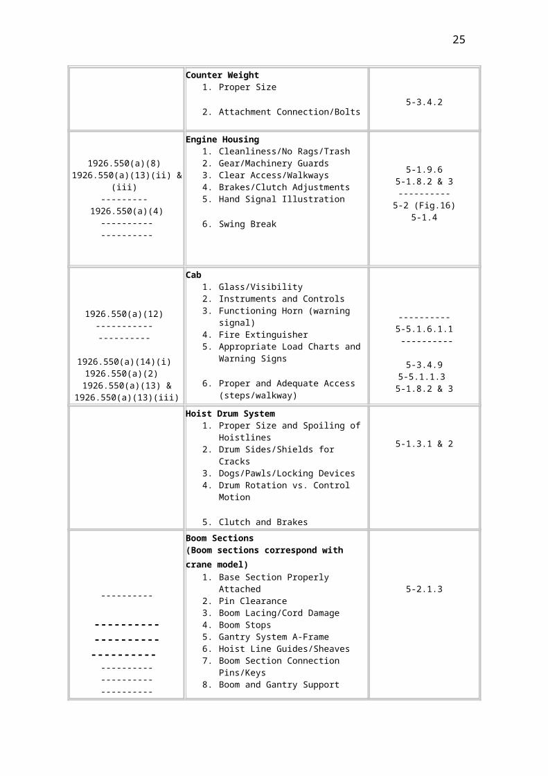
Table 4.8C shows the items that need to be examined for the Manitowoc 4100 150 Ton Lattice Boom Crawler Crane and their corresponding applicable OSHA 1926 and ANSI B30.5 Standards.
Table 4.8C – 150 Ton Lattice Boom Crawler Crane STANDARD
(29 CFR 1926.550)INSPECTION ITEMS ANSI
B 30.5
18

Track Crawler System 1. Lubrication 2. Connection Bolts
3. Drive Chain (slack & wear)
5-1.9.95-2.1.35-2.1.2
Turntable/Crane Body (Upper Works)
1. Assure Level/Stability 2. Wear/Gear/Teeth/Rollers 3. Cracks
4. Bolts/Pins - Assure Securely Attached
5-1.1 & 5-1.2
Counter Weight 1. Proper Size
2. Attachment Connection/Bolts
5-3.4.2
1926.550(a)(8) 1926.550(a)(13)(ii) & (iii)
--------- 1926.550(a)(4)
--------------------
Engine Housing 1. Cleanliness/No Rags/Trash 2. Gear/Machinery Guards 3. Clear Access/Walkways 4. Brakes/Clutch Adjustments 5. Hand Signal Illustration
6. Swing Break
5-1.9.6
5-1.8.2 & 3----------
5-2 (Fig.16)5-1.4
1926.550(a)(12) ----------- ----------
1926.550(a)(14)(i) 1926.550(a)(2)
1926.550(a)(13) & 1926.550(a)(13)(iii)
Cab 1. Glass/Visibility 2. Instruments and Controls 3. Functioning Horn (warning signal) 4. Fire Extinguisher 5. Appropriate Load Charts and
Warning Signs
6. Proper and Adequate Access (steps/walkway)
----------5-5.1.6.1.1
----------
5-3.4.95-5.1.1.3
5-1.8.2 & 3
Hoist Drum System 1. Proper Size and Spoiling of
Hoistlines 2. Drum Sides/Shields for Cracks 3. Dogs/Pawls/Locking Devices 4. Drum Rotation vs. Control Motion
5. Clutch and Brakes
5-1.3.1 & 2
----------
----------
Boom Sections(Boom sections correspond with crane model)
1. Base Section Properly Attached 2. Pin Clearance 3. Boom Lacing/Cord Damage 4. Boom Stops 5. Gantry System A-Frame 6. Hoist Line Guides/Sheaves
5-2.1.3
19

--------------------
------------------------------
1926.550(b)
7. Boom Section Connection Pins/Keys
8. Boom and Gantry Support System
9. Jib Attachment/Backstops/Belly Slings(Jib Security Device)
Sheave System 1. Ensure Hoistline and Sheave Size
Match 2. Worn
3. Lubrication/Move freely
5-1.7.4
Load/Auxiliary Hook and Block System
1. Sheaves Function Smoothly 2. Hook Rotates Freely/Lubricated 3. Proper Becket
4. Properly Reeved
5-1-7.1-6
1926.550(a)(7) 1926.550(a)(7)(v)
----------------------
Wire Rope/Hoist Line1. Overall Condition 2. End Connections 3. Lubrication
4. Clips
5-1.7.6--------------------
---------- ----------
1926.550(a)(9) 1926.550(a)(15)
Safety Devices 1. Anti-Two Block Devices 2. Boom Backstop Devices 3. Swing Radius Warning Devices
4. Job or Site Specific Devices/System/Program for work near electric power and use of personnel hoisting platforms)
5-1.1.9
5-2 (Fig. 17)
Additional references:1926.550(a)(1) ---- Crane used in accordance with manufactures specification.1926.550(a)(5) ---- Inspection: Competent Person.1926.550(a)(6) ---- Annual Inspection Record.1926.550(a)(16) ---- No modifications without written approval from manufacturers.
20

Appendix A - General Terms and Definitions
Auxiliary Hoist A supplemental hoisting unit, usually of lower load rating and higher speed than the main hoist.
Axis of Rotation The vertical axis around which the crane's superstructure rotates.
Boom
In cranes and derricks usage, an inclined spar, strut, or other long member supporting the hoisting tackle. Also defined as a structural member attached to the revolving superstructure used for guiding and acting as a support for the load.
Boom Angle IndicatorAn accessory device that measures the angle of the boom base section centerline to horizontal.
Boom Stops A devise used to limit the angle of the boom at its highest position.
Brake A device used for retarding or stopping motion by friction or power means.
Block Sheaves or grooved pulleys in a frame provided with hook, eye, and strap.
Crane A machine consisting of a rotating superstructure for lifting and lowering a load and moving it horizontally on either rubber tires or crawler treads.
Counterweight Weights used for balancing loads and the weight of the crane in providing stability for lifting.
Deck The revolving superstructure or turntable bed.
Drum The spool or cylindrical member around which cables are wound for raising and lowering loads.
Gantry A structural frame work (also known as an A Frame) mounted on the revolving superstructure of the crane to which the boom supporting cables are reeved.
21

Headache Ball A heavy weight attached above the hook on a single line or whip line to provide sufficient weight to lower the hook when unloaded.
Holding Brake A brake that automatically sets to prevent motion when power is off.
Jib An extension attached to the boom point to provide added boom length for lifting specified loads.
Load The weight of the object being lifted or lowered, including load block, ropes, slings, shackles, and any other ancillary attachment.
Load Block The assembly of the hook or shackles, swivel, sheaves, pins, and frame suspended from the boom point.
Main Hoist Hoist system or boom used for raising and lowering loads up to maximum rated capacity.
Mechanical Load Brake
An automatic type of friction brake used for controlling loads in the lowering direction. This device requires torque from the motor to lower a load but does not impose additional loads on the motor when lifting a load.
Outriggers Support members attached to the crane's carrier frame which are used to the crane and may be blocked up to increase stability.
PawlAlso known as "dog". It is a gear locking device for positively holding the gears against movement.
Pendants Stationary cables used to support the boom.
RadiusThe horizontal distance from the axis of rotation of the crane's superstructure to the center of the suspended load.
Reeving The path that a rope takes in adapting itself to all sheaves and drums of a piece of equipment.
Running Sheave Sheaves that rotate as the hook is raised or lowered
Superstructure The rotating frame, gantry and boom or other operating equipment.
Test LoadAny load or force, expressed in pounds, used for testing or certifying the limitations within acceptable tolerances of the anticipated load.
Two-BlockThe condition in which the lower load lock or hook assembly comes in contact with the upper load block or boom point sheave assembly.
Quadrant of OperationThe area of operation that the lift is being made in. Usually divided into four quadrants, i.e. front, rear and side(s) - left side and right side.
22

Appendix B - General Load Charts and Operational Considerations
General Load Charts: Manufacturer's operating notes supplied with the machine contain important information concerning proper set-up, operation and additional points that need to be considered when calculating load handling capacities of cranes. Mistakes in calculating capacity can cause accidents. Several factors to be considered when calculating a cranes load capacity, including the following:
A. Load Radius: the horizontal distance between the center of the crane rotation to center of the load.
B. Boom length: including the jib, swing away extension or any other attachments that may increase length of the boom.
C. Parts of line: D. Quadrant of operation: the area of operation that the lift is being made in; note
different quadrants usually have lower lifting capacities. E. Boom angle: the angle formed between the horizontal plane of rotation and
center line of the boom. F. Weight of any attachments: jib, lattice extension or auxiliary boom point. G. Weight of handling devices: ball, block, and/or any necessary rigging.
Operational Considerations: A. When working at boom lengths or radii between the figures shown on the load
capacity chart, the next lower capacity rating should be used. It is dangerous to guess the capacity for boom lengths or radii between those listed on the rating plate.
B. It is very dangerous to lift a load without knowing whether it is within the rated capacity while expecting the crane to start to tip to warn of an overload. Cranes may suddenly tip over or the boom may collapse if the load is too heavy.
C. Always stay within the rated capacity. Operators must reduce the load capacity under adverse field conditions until, it is determined, the machine can safely handle the lift.
D. Loads shall not be allowed to exceed rated load capacity and working radius. E. Do not use counterweights heavier than the manufacturer's recommended
weight. F. Even a light wind can blow the load out of control, collapse booms, or tip
machines.
Winds aloft can be much stronger than at ground level.G. Proper precautions shall be taken when the velocity of wind exceeds 20-mph. H. Crane capacity can be adversely effected when the machine set is not level. I. Do not lift loads when winds create an unsafe or hazardous condition. Booms
should be lowered, if possible, under high wind conditions. J. Foot pedal brake locks are furnished on some cranes to allow the operator to
rest his legs when suspending the load for short periods of time. Operators should keep their feet on the pedals while foot pedal brake locks are in use. Brakes may cool allowing the load to fall.
K. No one, except the oiler, instructor or designated person should be allowed on a crane with the operator when the crane is in operation.
23

Appendix C - Basic Crane Components
In addition to reviewing the OSHA and American National Standards Institute (ANSI) standards/requirements for mobile construction cranes, it is important that each inspector have a basic knowledge of crane components and their general purpose. The following is a list of basic crane components which should be included in any inspection. In addition to a description or purpose statement photographs are provided to help the inspector recognize each item. The list may not be inclusive, but is intended to be an aid for an inspector who may not be a crane expert.
1. Manufacturer's Operating Manual INSPECTION ITEMS
24
2. Machine Guarding
1. Manufacturer's operating and maintenance manuals shall accompany all mobile hoisting equipment. These manuals set forth inspection, operation, and maintenance criteria for each mobile crane and not generally available from any other source.
1. Manufacturer's Operating Manual
2. All exposed moving parts such as gears, chains reciprocating or rotating parts are to be guarded or isolated.
2. Machine Guarding
3. Swing Clearance Protection 4. High Voltage Warning Signs INSPECTION ITEMS
3. The swing radius of the counterweight shall be established and guarded to prevent personnel or other equipment from being struck by the counterweight. Special attention shall be given to guarding of the swing radius when near buildings or other structures. The swing radius guarding is intended to simply be a warning device and not necessarily a barricade guard rail. There are no strength requirements associated with swing radius protection.
25

3. Swing Clearance Protection
4. High voltage warning signs shall be displayed on the exterior of the equipment on each side and on the counterweight of the crane.
4. High Voltage Warning Signs5. Boom Stops 6. Jib Boom Stops INSPECTION ITEMS
5. Boom stops are telescoping, shock absorbing, or hydraulic-type safety devices designed and installed in a manner to stop or shut off power to the boom controls. The purpose of the boom stops is to prevent the boom from being raised to a point where the center of gravity is shifted to the rear of the crane causing the boom to fall backwards from to lack of resistance and/or control of boom movement.
Boom stops can be inspected and checked for proper function by raising the boom very slowly until contact is made and power for boom movement is stopped. 5. Boom Stops
6. Jib stops are restraints designed to prevent the jib from being raised to the point that it overturns onto the boom sections. Jib stops, like boom stops, are telescoping, shock absorbing, hydraulic devices, designed to warn the operator that the jib load block has approached the point at which overtipping/overturning is possible if raising the load line continues.
6. Jib Boom Stops
26

7. Boom Angle Indicator8. Boom Hoist Disconnects INSPECTION ITEMS
7. Boom Angle Indicators are required to indicate the angle of the boom tip from the base section on a horizontal plane. They may be either mechanical (activated by gravity) or electronic, with a display readout in the cab. Accurate readout of boom angle determines load capacity and working radius.
7. Boom Angle Indicators
8. Boom Hoist Disconnects are designed to automatically stop the boom from hoisting when the boom reaches a predetermined high angle
8. Boom Hoist Disconnects
9. Anti-Two Block Devices 10. Power Controlled Lowering INSPECTION ITEMS
27

9. Anti-Two Block Devices are designed to prevent a hoist block and/or load from being hoisted into contact with the boom tip by putting sufficient stress on the wire rope that it is either cut or stressed to the point that the line separates and the load falls onto someone or something. ANSI requires that all hydraulic cranes be equipped with anti-two block devices.
9. Anti-Two Block Devices
10. All functions of hydraulic cranes feature "power controlled lowering". Safety devices known as "holding valves" or "counter balance" valves, which prevent uncontrolled decent in the event of hydraulic pressure loss. To test the effectiveness of these safety devices, retract the cylinders or lower the hoist drum with the engine not running. This would apply to the boom lift and extension cylinder as well as the outrigger cylinders and hoist drums. No movement should take place without hydraulic pressure.
10. Power Controlled Lowering
11. Leveling Indicator Devices12. Sheaves INSPECTION ITEMS
28

11. Leveling of the crane is extremely important. If a crane is out of level more than 1o it exerts a side load on the crane, and can effect structural capacity. It also can increase the load radius when the crane is rotated to another quadrant of operation.
11. Leveling Indicator Devices
12. All sheaves should be checked for cracks, grooving, or damage from two-blocking. Undue looseness in the bearing or bushing should be noted. The sheave's groove surface should be smooth and slightly larger than the wire rope being used. It should be checked with a sheave gauge to be sure it is the proper size for the wire rope being used. On most hydraulic cranes, sheave guards which prevent the wire rope from coming off the sheave, are removable pins. Be sure that all of these pins are in place.
12. Sheaves
13. Main Hoist and Auxiliary Drums14. Main Boom, Jib and Boom Extensions INSPECTION ITEMS
29

13. Drum lagging and flanges should be inspected for cracks or other deficiencies and winch mounting bolts should be checked. Any undue movement of the drum on its bearings should be noted. The wire rope anchoring to the drum should meet the manufacturers specifications and must not be "overspooled". In other words, with the rope fully spooled on the drum, the drum flanges must extend above the top wrap of the rope. Any spoiling devices, such as rollers, or drum rotation indicators, must be functioning properly.
13. Main Hoist and Auxiliary Drums
14. All components of the boom assembly should be checked for cracks, bends, or other deformities. On hydraulic cranes, special attention should be given to the topside of the boom where the extension sections exert an upward force. All connecting pins and bolts should be checked. Wear pads should be adjusted properly or replace if necessary.
14. Main Boom, Jib and Boom Extensions
15. Load Hooks and Hook Block16. Hydraulic Hoses, Fittings and Tubing INSPECTION ITEMS
30

15. Hooks should be examined to see if they are cracked or distorted beyond allowable tolerances. No welding or heating should be done on hooks. Hooks and blocks should be labeled as to their capacity and weight.
Connecting bolts on block cheek plates should be checked. Hook swivels and sheave guards should also be checked.
15. Load Hooks and Hook Block
16. All hydraulic hoses, fittings, swivels, and tubings should be checked for leaking. On flexible hoses, be sure that the working pressure stamped on the hose is more than the working pressure it will be exposed to.
16. Hydraulic Hoses, Fittings and Tubing
17. Outriggers18. Load Rating Chart INSPECTION ITEMS
31

17. Outrigger beams and housings should be checked for cracks or distortions. Outrigger floats, or pads, should be checked for damage. The floats must have the capacity to be securely attached to the outriggers. Outrigger beams should be marked to indicate when they are fully extended.
17. Outriggers
18. A durable load rating chart for the specific model and serial number of the crane shall be accessible to the operator at his operating or work station. All limitations, warnings, specifications and safety data should be displayed
18. Load Rating Chart
19. Wire rope20. Cab INSPECTION ITEMS
32

19. Wire rope should be removed from service when the conditions listed in 29 CFR 1926.550(a)(7) are found. They include outside wire wear, reduction in diameter, broken wires, distortion, corrosion, or heat damage. Special attention should be given to standing rope, such as pendants, at the end fittings. It should be determined that the wire rope is the proper diameter, length, and type of construction for that particular crane and it should be spooled evenly on the hoist drum.
19. Wire rope
20. The cab should be clean and free from clutter. All controls should be labeled as to their function and free to return to the neutral position when released, unless designed to do otherwise. All gauges and warning lights should be operable and a fire extinguisher (at least 5-BC) should be mounted in the cab. The seat should be securely attached and the cab door should open outward and operate smoothly. Electrical and other warning signs should be posted in the cab. All glass must be safety glass with no cracks or distortions.
20. Cab
33