Embed Size (px)
Citation preview

MINI-CRAWLER CRANE
MODEL
OPERATION&
MAINTENANCEMANUAL
OMURW295CUR200804BPRINTED IN JAPAN
HEAD OFFICE : Furukawa Bldg. 3-14, Nihonbashi Muromachi 2-chome, Chuo-ku, Tokyo, 103-0022 Japan


0-1
INTRODUCTION
Crane model
Specification
Serial number
Code number
MODEL
SPEC.
CODE NO.
SERIAL NO.
CAPACITYFURUKAWA UNIC
CORPORATIONTOKYO JAPAN
MADE IN JAPAN
LBS
Request to those who operate the craneThe operator’s manual describes correct operation methods, simple inspection, and ser-vice for the UNIC crane.Be sure to read this manual carefully to carry out correct and safe operation of the crane.Operate the crane after you have understood the contents of this manual.
Although we take all possible measures to ensure quality of the crane, you are requestedto contact our business offices, UNIC sales agents, or authorized service stations when-ever you have anything you do not understand.
♦For making inquiriesWhen making inquiries, ordering spare parts, and requesting repairs, be sure to informus of the crane model, specification, serial number, and date of manufacture which areindicated on the name plate.
♦Name plate of the machine is located at the rear side of column.

0-2
TABLE OF CONTENTS
8.HOW TO REFER TO WORK-ING RANGE CHART ANDRATED LOAD CHART
q Working range chart ..................................8- 1
w Rated load chart .........................................8- 2
9.DESCRIPTION OF EACHCONTROL DEVICE
q Overwinding alarm ...................................9- 1
w Automatic stop for over-winding .............9- 2
e Boom angle chart ......................................9- 3
r Warning horn ............................................9- 7
t Hook safety latch .......................................9- 8
y Automatic stop for leaving minimum wire rope ........9- 8
u Specifications on turn over prevention device ............9- 9
10. HOW TO OPERATE CARRI-ER
q Designation of each control lever and its location ..10- 1
w Preparation before operation .................10- 2
e How to operate .......................................10- 3
r How to crawl .........................................10- 6
11. HOW TO OPERATE CRANE q Designation of each control lever
and location .........11- 1
w Preparation before operation .................11- 2
e Procedures to set up outriggers ..............11- 3
r How to operate boom for “derricking” ..11- 7
t How to hoist and lower the hook ...........11- 8
y How to telescope boom .........................11-10
u How to slew boom .................................11-11
i How to store crane .................................11-15
o Procedures for storing hook ...................11-16
!0 How to store outriggers .........................11-17
!1 How to switch manual operation mode to/from radio remoto control mode .......11-19
!2 How to operete outriggers when in an emergency .........11-21
SETUP OF THIS MANUAL .....0- 4
1. FOR SAFETY OPERATION q Request to operators .................................1- 1
2. SAFETY PRECAUTIONS ONCARRIER OPERATION
q Before operation .......................................2- 1
w During operation .......................................2- 2
e When loading and unloading ....................2- 3
r After operation ..........................................2- 4
3. SAFETY PRECAUTIONS ONCRANE OPERATION
q Before operation .......................................3- 1
w During operation .......................................3- 2
e After operation ..........................................3- 3
4. DESCRIPTION OF CARRIEREQUIPMENT ................................4- 1
5. DESCRIPTION OF CRANEEQUIPMENT ................................5- 1
6. NAME PLATESq Description of name plates (Stickers) ......6- 1
w Stickers in detail .......................................6- 2
7. DEFINITION OF TERMSq Extension and spread of outriggers .........7- 1
w How boom-sections are extended ............7- 3
e Net rated load ...........................................7- 4
r Rated load ................................................7- 4
t Lifting capacity ........................................7- 4
y Working radius ........................................7- 4
u Boom length ............................................7- 4
i Boom angle ..............................................7- 4
o Lift above ground ....................................7- 4

0-3
12. U-WAVE, RADIO REMOTOCONTROL DEVICE
q Request to those who operate the crane ....12- 1
w Safety precautions ..................................12- 2
e Designation of each equipment .............12- 5
r Inspection before crane operation ..........12- 8
t How to switch crane operationmode .....12-10
y How to operate the crane through radio control operation ....12-12
u How to replace batteries of transmitter ...12-34
i Daily checks, trouble inspection ............12-37
13. MAINTENANCE ANDINSPECTION OF CARRIER
q Inspection before operation ....................13- 2
w Inspection and Maintenance which is to be car-
ried out every 250 hours or 3 months .......13- 9
e Storage ....................................................13-11
r Fitting safety covers ................................13-12
t Maintenance and inspection of engine ...13-12
14. MAINTENANCE ANDINSPECTION OF CRANE
q Inspection before operation ...................14- 2
w Cleaning .................................................14- 3
e Inspection of bolts mounting slewing bearings ........14- 3
r Replacement of wire rope ......................14- 4
t Replacement of expendable parts ..........14- 8
15. WATER SUPPLY AND LUBRI-CATION TO CARRIER
q Precaution when carrying out lubrication ..........15- 1
w List of recommended lubricant ..............15- 2
e Filling water and lubrication chart..........15- 4
TABLE OF CONTENTS
16. LUBRICATION TO CRANEq Precaution when carrying out
lubrication .........16- 1
w List of recommended lubricant ..............16- 2
e Lubrication chart.....................................16- 3
r Lubrication..............................................16- 4
17. MAJOR SPECIFICATIONSq URW295CE (5-section boom) ..............17- 1
18. MODE INDICATOR LAMP(Control box) ..............................18- 1
19. MEASURES TO BE TAKENIN AN EMERGENCY .........19- 1

0-4
URW295CU
URW295CU
R
ModelSpec.
URW295 CU series
Designation (example)
Manual specification
With radio remote controller
SETUP OF THIS MANUAL
SETUP OF THIS MANUAL
Crane covered in this manual have some difference in operation in accordance with thespecifications of with or without radio remote controller.Difference in operation due to crane specifications is separately illustrated in this manualfor each specification.Refer to separate “Instruction manual of radio controller” for operation and/or mainte-nance of the radio remote controller.
1. Designation of specificationsCrane specifications covered in this manual are divided into two: crane with or withoutradio remote controller.

1-1
1. FOR SAFETY OPERATION
♦ Never failed to observe and described in the manual asthey are of great importance in safety and the crane operation.
. .Failure to observe this may invite an accident resulting in injury or death.
. .Failure to observe this may cause damage to the crane.
♦ Store this manual where it is easily accessible to read it over and over again.♦ Failure to observe the right operation and maintenance/inspection illustrated in this manual
may cause trouble in the crane and may invite an accident, and this will not only shorten itsservice life but will impair safety in the crane operation.Please remember, in such cases, that no warranty will be given even if the crane is withinvalid warranty period.
♦ In order to prevent injury or death to crane operators and to those who stand close to craneoperating area due to operational mistake, caution plates are stuck on the crane. You are requested to read them carefully.
♦ Do not alter the crane.★ If you want to make an alteration, contact with UNIC sales agent or an authorized service
shop.★ UNIC does not bear any responsibility for troubles and/or accidents due to unauthorized
alteration.
qRequest to customers
★ Read preventive measuresagainst danger and cautionsstated in this manual for properunderstanding.
★ Most accidents related to thecrane occur due to operation,maintenance, and inspectionwhich have failed in observingbasic safety regulations.
Observe all the safety regulations !
CAUTIONWARNING
WARNING
CAUTION

MEMO
2-1
1 Dress neatly and wear protectors such ashelmet, safety shoes, and gloves without
fail.★Do not wear baggy clothes and accessorieswhich can be caught by control levers and fit-tings, and oil-stained working clothes whichmay catch fire.
2 Be sure to make inspection before oper-ation and periodical voluntary inspec-
tion.If found something wrong, repair it immedi-ately.
3 The crane is prohibited to crawl on apublic road by the road traffic law.
4 Check that no safety covers have beenleft removed.
★It is very dangerous to start the engine, tooperate the crane with the safety coverremoved as the driving mechanism is directlyexposed.
5 Be sure to stop the engine before refuel-ing or supplying and changing lubricant.
A fire source such as smoking cigarette inmouth is strictly prohibited.Failure to observe this may cause a fire.
6 When starting the engine in a small lim-ited area or indoors, open the windows
and doors for well ventilation.★Poor ventilation may invite an exhaust gaspoisoning.
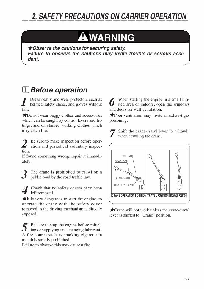
7 Shift the crane-crawl lever to “Crawl”when crawling the crane.
qBefore operation
TRAVEL LEVER STAND
LOCK LEVER
STAND LEVER
TRAVEL LEVER
CRANE OPERATION POSITION TRAVEL POSITION STOWAGE POSITION
★Crane will not work unless the crane-crawllever is shifted to “Crane” position.
2. SAFETY PRECAUTIONS ON CARRIER OPERATION
★Observe the cautions for securing safety.Failure to observe the cautions may invite trouble or serious acci-dent.
WARNING

2-2
SAFETY PRECAUTIONS ON CARRIER OPERATION
1 The machine employs particularly smalltruck to facilitate working in a restricted
space.Since high performance crane is mounted onthe small truck, it has been built with a highercenter of gravity.★Take special care not to overturn the cranewhen crawling on a unleveled ground.
2 When crawling the crane, be sure to putoutriggers in a condition of being stored
and store the hook.
3 Do not run the crane with a cargo hoist-ed or without the crane being stored.
4 Special care must be taken to run thecrane slowly when making a sharp turn
and crawling on a rough road.
5 When running over a bump, be sure toslow down the crane and direct it
straight to the bump to avoid unnecessaryshock to the crane body.
6 Be sure to use a foot-board to run over aramp of more than 15cm.
7 Crawl the crane at low speed on a slope.
8 Be sure to use a pallet against the rubbercrawler when parking the crane on a
slope.
9 Do not make an abrupt stop and start,and change a course on a slope.
10 When crawling up and down a slope,operate the crane by standing at a
higher position than the crane body.
11 Do not use the crane on a steep slopeof more than 10 degrees.
Pay attention that the crane will not lean bymore than 10 degrees due to jolting whenoperating/crawling on a unleveled road.
Less than 10 degrees
12 Do not run the crane over bumpyarea, lying rocks with sharp edges,
rough solid rock, small broken stones, edgesof steel plate, steel bars for reinforcement,scrap metals, and waste materials and on aroad such as in riverside where covered withmany stones which may remarkably shortenservice life of rubber crawler.
13 Do not turn the crane body in suchway that the rubber crawler makes a
simultaneous rotation by turns as this causesremarkable wear of rubber crawler due toquick movement.
14 Do not take an article or an animal onthe crane.
★It may invite critical situation due toabrupt swing or shift of center of gravity.
wDuring operation

2-3
SAFETY PRECAUTIONS ON CARRIER OPERATION
1 When loading and unloading the crane,use a non-slip foot-board with a enough
capacity of strength, width, and length andrun the crane straight up and down veryslowly.In addition, operate it by standing at a higherposition than the crane body.Changing direction of the crane on the foot-board may cause the crane to fall off.
2 Stop the engine, apply parking brake,and put drags to wheels to secure the
mounting vehicle when loading and unload-ing the crane.★Failure to observe this may cause the craneto fall off because the vehicle shift while it isbeing loaded and unloaded.
eWhen loading and unloading15 Do not park the crane over a place
where withered grass or straw arebeing spread.★It may cause a fire by heat of exhaust pipeor exhaust gas.
( )
( )
( )
Be sure to drive both sides of crawler in the same direction for making a turn.
Do not drive both sides of crawler in the opposite direction each other.
Do not drive only one side of the crawler.
★For the white (or gray) crawler, observe the driving strictly in terms of its characteristics.
16 To avoid rubber crawler damage.

2-4
SAFETY PRECAUTIONS ON CARRIER OPERATION
1 Return the crawling lever and run theengine at a low speed.
2 Shift the crawling lever to “Crane” posi-tion.
3 Stop the engine and remove dirt anddust stuck on the crane body.
★Since dust stuck on the battery, electricwiring, and engine related components suchas muffler may cause a fire in particular, besure to remove it.
4 Cover the crane or store it in a storagehouse to prevent it from being accessed
by unrelated persons such as children.★Cover the crane after heated sections havebeen cooled off.Putting a cover on while the crane body isstill hot may cause a fire.
5 Remove the starter switch key to keep itsecurely.
6 Disconnect a battery cable before thecrane is to be stored for a long period of
time.★Failure to disconnect it may cause a fire ascables short-circuited by gnawing animalssuch as rat.
rAfter operation
Cable (-) Disconnect

3-1
3. SAFETY PRECAUTIONS ON CRANE OPERATION
qBefore operation
1 Be sure to make inspection before opera-tion and periodical inspection for sling-
ing implements.★If a defective slinging implement is used,fall of lifted cargo may result.
2 Shift the crawling lever to “Crane” posi-tion.
TRAVEL LEVER STAND
LOCK LEVER
STAND LEVER
TRAVEL LEVER
CRANE OPERATION POSITION TRAVEL POSITION STOWAGE POSITION
3 Turn ON the over-winding alarm switch.
4 Make sure that each safety device isalways functioning properly.
★Be sure to turn ON the over-winding alarmswitch before starting crane operation.
5 Keep a safety distance away from thehigh-voltage power line to avoid an
electric shock.★The crane is not electrically insulated.
6 Do not operate the crane when windvelocity exceeds 10m/sec. and/or while
thundering.★Crane operation while strong wind isblowing can cause fall of a lifted cargo oroverturn of the crane as the boom and/or alifted cargo are hit by a gust of wind.
7 Pay attention that anyone except personsconcerned will not enter within a work-
ing radius of the crane.★Take good care to carry out safety opera-tion by keeping a close watch around theworking area.
8 Make sure that the ground on which out-riggers are to be set up is solid and firm.
★When setting up the outriggers on anunleveled ground or on a slope, be sure toplace a support (such as plank, steel plateetc.) under the outrigger foot flanges to keepthe crane level.In addition, when the crane is to be operatedon a soft ground, take the same measures toprevent the outrigger foot flanges from sink-ing into the ground when a cargo is lifted up.
9 Lift up the crawler by approx. 50mmfrom the ground.
10 Operation with the crane kept leaningmakes it unstable when a cargo is
lifted up.Such operation can cause the crane to beoverturned.
11 In normal crane operation, be sure toset up the crane level with the outrig-
gers fully extended.
12 Do not stand under or in front of thehook when unhooking as it swings.
13 Do not try adjusting hydraulic equip-ment.
14 Confirm that the crane makes anautomatic stop by turnover preven-
tion device when overloaded.

3-2
SAFETY PRECAUTIONS ON CRANE OPERATION
wDuring operation
1 Pay attention that the hook will not beover-wound.
Be sure to turn ON the “over-winding alarmswitch”.★Remember that the hook is wound upwhen boom is extending.★If the hook hits against the boom top dueto being over-wound of the hook, it maycause damage to wire rope and the sheaves atthe boom top and may cause the fall of liftedcargo.
2 Operate each lever slowly and smoothly.
★An abrupt lever operation with a cargo lift-ed gives an excessive shock to the cranewhich may cause damage to the crane and/oroverturn due to swing of a lifted cargo.
3 Slew the crane at low speed.
★Swing of a lifted cargo increases workingradius of the crane which may cause it to beoverloaded.
4 If the engine speed is too slow whenoperating the crane, control the accelera-
tor lever to increase it. ★Crane operation with the engine (andpump) running at low speed may cause acargo hoisted up to swing due to pulsation ofthe engine.This is not a malfunction but impairs smoothcontrol of the crane.
5 Overloaded operation is strictly prohib-ited.
★Crane operation with a load exceeding therated load hoisted may cause damage or over-turn to the crane.★Do not put too much confidence on theturnover prevention device.It functions just as an auxiliary device.It is the principle that you should persistently
observe the operation within rated load.If an alarm sounds due to decrease of groundreaction, lower the operating speed immedi-ately to shift the crane to safer side.★If ground reaction decreases further, thecrane stops following functions automaticallywhen you should pay special attention to thecrane because it may roll over due to swingof a lifted cargo.
◎Winding-up hook ◎ extension of boom
◎ lowering boom ◎ Slewing
6 Pulling a cargo sideways, straight, orobliquely is strictly prohibited.
★These operation may cause slewing mem-bers, booms, columns, and derrick cylinder tobe damaged.
7 When a cargo to be lifted is detachedfrom the ground, stop lifting it up tem-
porarily to confirm safety.★When a cargo is lifted off the ground, stoplifting it up temporarily to make sure that thecargo is kept horizontally, the crane main-tains its stability, and the rope slinging up thecargo is positioned properly.Then lift it up again after making sure of thesafety.★For lowering a cargo, stop lowering itimmediately before it touches the groundthen lower it again gradually.
8 Do not leave from operating positionwith a cargo hoisted.
★Lower a hoisted cargo onto the groundbefore leaving the operation site.
9 Do not get up on a cargo being hoisted.
★This may cause a fall from the cargo beinghoisted.

3-3
SAFETY PRECAUTIONS ON CRANE OPERATION
10 Do not stay under a hoisted cargo.
11 Pay attention that wire ropes will notbe paid out unnecessarily to prevent
ropes from being wound around the drumirregularly.★Operation such as paying out wire ropesfurther with a cargo placed on the ground,retraction and/or lowering boom whichloosen the ropes to cause them irregularwinding which results in remarkable shorten-ing service life of the ropes.★Wind the first layer of rope firmly and reg-ularly around the drum.★Correct kinks of rope immediately with amallet.
12 Pay extra attention to undergroundcrane work in which the hook must
be lowered further than the work on theground. ★When paying out wire ropes, be sure thatmore than 3 turns of rope must always be lefton the drum.
13 Stop the crane operation when tem-perature of hydraulic oil exceeds
147ºF (80°C.)★Oil temperature is apt to rise easily ifrepeated operation of winding up and downthe hook, especially in a high lift, is required.★Excessive high temperature of hydraulicoil damages high-pressure hoses and gasketsbeing employed to cause the oil to spout outso that a scald may result.
14 Do not touch the engine and the hoodin the side with a bare finger as they
become too hot.
eAfter operation
1 Make sure that the booms, the outrig-gers, and the hook have been stored
before crawling the crane.
2 Do not carry out maintenance andinspection while temperature of either
hydraulic oil or gear oil is still high.★Temperature of both hydraulic and gear oilis high immediately after crane operation sothat accumulated high pressure still remains.Removing filling cap, draining oil, or replac-ing oil filter while temperature is still highallows hydraulic and/or gear oil to spout outand a scald may result.
3 Since temperature on the engine and thehood in the side is too high immediately
after crane work, touch them after they havebeen cooled down.
4-1
4. DESCRIPTION OF CARRIER EQUIPMENT
10 9
6
3
8
11 14 7 1312
1 4 5 2

4-2
DESCRIPTION OF CARRIER EQUIPMENT
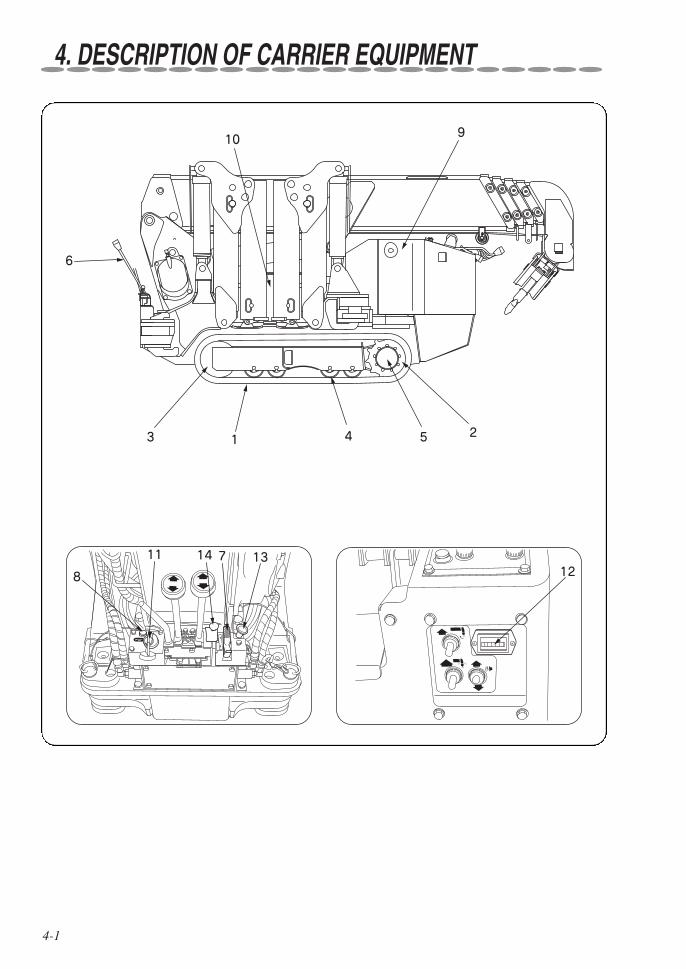
1. Rubber crawlerCored bar and steel fabric (cords) are inte-grally molded in the rubber which is of thesame quality as automobile tire.
2. Wheel sprocketIt transmits driving power to the rubbercrawler to allow the crane to crawl.
3. Idle rollerThis is a roller which gives a proper tensionto the rubber crawler.
4. Truck rollerThis supports the weight of crane and rolls onthe rubber crawler.
5. Crawling motorHydraulic motor with reduction gears whichtransmits driving power to the wheel sprocketis built inside.
6. Crawling leverThis is to change crawling speed and direc-tion.
7. Accelerator leverThis is to control engine speed.
8. Horn switch
9. Fuel tankFuel to be used is leadless gasoline.
10. Hydraulic oil tankThis is filled with hydraulic oil which com-monly supplies both to the carrier and to thecrane.
11. Starter switchThis is a switch to start and stop the engine.
12. Hour meterThis indicates total engine running time.
13. Choke knobThis is pulled when starting the engine incold weather.
14. Lock lever

5-1
5. DESCRIPTION OF CRANE EQUIPMENT
2 4 6 15 8 7 1 17
9
10
12
14
11
20 18
16
3
5
9
10
19
13
5-2
DESCRIPTION OF CRANE EQUIPMENT
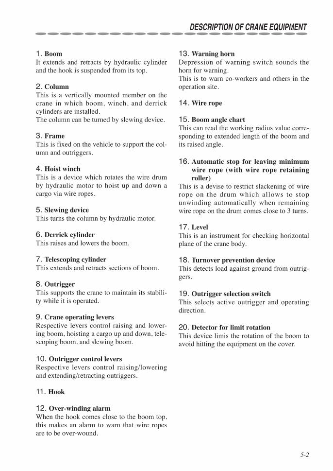
1. BoomIt extends and retracts by hydraulic cylinderand the hook is suspended from its top.
2. ColumnThis is a vertically mounted member on thecrane in which boom, winch, and derrickcylinders are installed.The column can be turned by slewing device.
3. FrameThis is fixed on the vehicle to support the col-umn and outriggers.
4. Hoist winchThis is a device which rotates the wire drumby hydraulic motor to hoist up and down acargo via wire ropes.
5. Slewing deviceThis turns the column by hydraulic motor.
6. Derrick cylinderThis raises and lowers the boom.
7. Telescoping cylinderThis extends and retracts sections of boom.
8. OutriggerThis supports the crane to maintain its stabili-ty while it is operated.
9. Crane operating leversRespective levers control raising and lower-ing boom, hoisting a cargo up and down, tele-scoping boom, and slewing boom.
10. Outrigger control leversRespective levers control raising/loweringand extending/retracting outriggers.
11. Hook
12. Over-winding alarmWhen the hook comes close to the boom top,this makes an alarm to warn that wire ropesare to be over-wound.
13. Warning hornDepression of warning switch sounds thehorn for warning.This is to warn co-workers and others in theoperation site.
14. Wire rope
15. Boom angle chartThis can read the working radius value corre-sponding to extended length of the boom andits raised angle.
16. Automatic stop for leaving minimumwire rope (with wire rope retainingroller)
This is a devise to restrict slackening of wirerope on the drum which allows to stopunwinding automatically when remainingwire rope on the drum comes close to 3 turns.
17. LevelThis is an instrument for checking horizontalplane of the crane body.
18. Turnover prevention deviceThis detects load against ground from outrig-gers.
19. Outrigger selection switchThis selects active outrigger and operatingdirection.
20. Detector for limit rotationThis device limis the rotation of the boom toavoid hitting the equipment on the cover.

6-1
6. NAME PLATES
The machine is provided with stickers indicating caution (framed in box ) and specificationsas shown in the figure below, and in addition to that there are stickers showing control levers,switches, and instructions for lubrication.
qDescription of name plates (Stickers)
Machine identification
Rated loadsCaution, Battery
Caution , Watch-your-foot
Caution
Caution, Radio-controlled operation Caution , Mode Indicator Lamp
PROHIBITED AREA OF CRANE OPERATIONS
OUTRIGGER OPERATION FOR EMERGENCY
Caution
Caution, Travel Lever Stand
Caution, OUTRIGGERS
Turnover preventiondevice
Caution, Travelling

6-2
NAME PLATES
qStickers in detail
Sticker [BATTERY]
CAUTION, HIGH TEMPERATURE
094383140
CAUTION, BATTERYWrong handling of battery may cause to catch fire leading to explosion.Do not make it short-circuiting, spark-ing, and bring close to a fire. In addition, you may be blinded or burned by battery electrolytic solution.When your eye, skin, or clothes was stained with the solution, wash it away with plenty of water immediately.In case where the solution entered into someone’s eye accidentally, see a doc-tor to receive treatment after washing it with water.
Sticker [WATCH-YOUR-FOOT]
Mind yourfeet
Pay attention to yourfeet when extendingoutriggers. 094383110
Sticker [HIGH TEMPERATURE]
★Always keep the stickers clean so that they can be read easily.★ If any of the stickers has come off, stick it again or replace it with
new sticker.★When ordering stickers, specify the part number shown at the bot-
tom-right of the sticker concerned.
CAUTION
6-3
NAME PLATES
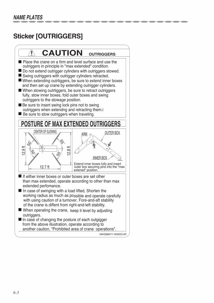
Sticker [OUTRIGGERS]
from the above illustration, operate according to
outer box securing pins into the "maxextened" position.
another caution, "Prohibited area of crane operations".
keep it level by adjustingWhen operating the crane,outriggers.
of the crane is diffent from right-and-left stability.with using caution of a turnover. Fore-and-aft stability
ssible and operate carefullyworking radius as much as poIn case of swinging with a load lifted, Shorten theextended perfomance.than max extended, operate according to other than maxIf either inner boxes or outer boxes are set other
outriggers when extendng and retracting them.i
outriggers in principle in "max extended" condition.Do not extend outrigger cylinders with outriggers stowed.
Be sure to insert swing lock pins not to swing
In case of changing the posture of each outgigger
Extend inner boxes fully and insert
Be sure to stow outriggers when traveling.
outriggers to the stowage position.fully, stow inner boxes, fold outer boxes and swingWhen stowing outrtiggers, be sure to retract outriggersand then set up crane by extending outrigger cylinders.When extending outrtiggers, be sure to extend inner boxesSwing outriggers with outrigger cylinders retracted.
Place the crane on a firm and level surface and use the
12.8
ft
12.9
ft
12.7 ft
INNER BOX
OUTER BOXARMCENTER OF SLEWING
09HQ86071-W295CUR
POSTURE OF MAX EXTENDED OUTRIGGERS
OUTRIGGERSCAUTION
50゚
50゚ 55゚
55゚
6-4
NAME PLATES
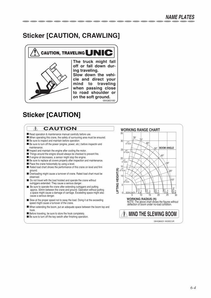
Sticker [CAUTION, CRAWLING]
094383160
CAUTION, TRAVELING
The truck might fall off or fall down dur-ing traveling.Slow down the vehi-cle and direct your mind to traveling when passing close to road shoulder or on the soft ground.
Sticker [CAUTION]
Overloading might cause a turnover of crane. Rated load chart must be
Rated load chart shows the performance of this crane on level and firm
09HQ86031-W295CUR
ground.
60°
302515105
5
10
15
25
30
35
BOOM ANGLE
OF HOOKLIFT
OF HOOKLIFT
OF HOOKLIFT
OF HOOKLIFT
OF HOOKLIFT
0°
10°
20°
30°
40°
50°
70°78°
20
020
BOOM LENGTHft
8.30ft
13.37ft
18.41ftft
23.39 28.3854321
LIFT
ING
HE
IGH
T(ft
)
MIND THE SLEWING BOOMhook.When extending the boom, put an adequate space between the boom top andspeed might cause a turnover of the crane.Slew at the proper speed not to sway the load. Doing it at the exceeding
approx. 50mm between the crane and ground. Operation without putting
cause a serious denger.a space might cause a damage of carriage. Exceeding space might also
Be sure to operate the crane after extending outriggers and putting
observed.
Be sure to turn off the power (engine, power, etc.) before inspectin andmaintenance.
NOTE: The above chart shows the figures withoutdeflection of boom under no-load condition.
WORKING RADIUS (ft)
WORKING RANGE CHART
Do not travel with the load hoisted and operate the crane without
Place the crane holizontally by using a level.Be sure to replace all covers properly after inspection and maintenance.If engine oil decreases, a sensor might stop the engine.Things around the enigne should always be checked to prevent fire.
Be sure to inspect and maintain before operation.When operating this crane, the safety of surrouning area must be ensured.Read operation & maintenance manual carefully before use.
CAUTION
Be sure to turn off the key swicth after finishing operation.Before traveling, be sure to store the hook completely.
outriggers extended. They cause a serious danger.
Inspect and maintain the engine after cooling the motor.

6-5
Sticker [RATED LOAD CHART]
NAME PLATES
RATED LOADS RATED LOADS
(lbs)
(lbs)
(lbs)
(lbs)
09HQ86040-W295CUR
BOOM SECTION
BOOM SECTION
BOOM SECTION
BOOM SECTION
130180220300380420530600700850350440500590700750920105012801280
25.023.021.019.018.016.015.0
200660
280850
3701000
4501100
5101200
6001350
7501750
8001950
10001950
11.010.08.07.06.05.04.53.0
7.0 8.0 9.5 10.0 11.0 14.0 15.0
11.0 13.0 15.0 16.0 17.0 18.0 20.0
properly.firm and level ground. Make sure lock pins are inserted
If even one outriggers are not fully extended, operatefigures of "not max ext. outriggers"position. Other than the above, operate according topin of each outrigger arm is inserted into the nomalextended to the max. extended position and a swing jack"Max extended outriggers" means inner boxes are
WORKING RADIUS(ft)
WORKING RADIUS(ft)
WORKING RADIUS(ft)
WORKING RADIUS(ft)
NOT MAX EXT.OUTRIGGERS
LOADRATED
OUTRIGGERSMAX EXT.
NOT MAX EXT.OUTRIGGERS
LOADRATED
OUTRIGGERSMAX EXT.
NOT MAX EXT.OUTRIGGERS
LOADRATED
OUTRIGGERSMAX EXT.
17.62
22.61
12.58
13.512.5
12.5
30055060085010001150125015501850100014501650215024502750305030503050
60095011001600225031504450445020002450285038004350495058506450
44506450
1+2+3+4+5
1+2+3+4
1+2+3
1+21
NOT MAX EXT.OUTRIGGERS
LOADRATED
OUTRIGGERSMAX EXT.
CAUTION
and stability of crane.condition. The rated loads are also based on strengthradiuses including the deflection of boom under loadlevel ground and are based on the actual working
4
4
away from boom even a bit. when mark in the side of boom moves1+2+3+4+5
boom is extended even a bit. Do according to1+2+3+4
4
Operate according to the figures of when boom 31+2+3is extended even a bit. Do according to when
Boom means boom is extended up to mark.1+2+3+4
3
the crane. Extend outriggers fully and Place them onImproper set-up of outriggers may cause a turnover ofaccording to the figures of " not max. ext. outriggers".
The rated loads show the performance of the crane on
12.0
27.59
Sticker [MODE INDICATION LAMP]
The mode selection switch opposite to the mode indicator lamp allows
When mode indicator lamp is OFF, manual operation can be performed.When mode indicator lamp is ON, radio-controlled operation can be performed.
Follow instructions of the instruction manual.Flashing of the mode indicator shows abnormality of operation or the equipment.
selection of ON and OFF of radio-controlled operation.
The above table shows the main mode indication. For details, see the instructions.
MODE INDICATORCAUTION
09HP81010-W095CDE
MODE INDICATOR LAMP
MODE INDICATOR
OUTRIGGER MODE ONOFF MANUAL
RADIO CONTROL
ONOFF
LEAVING MINIMUM WIRE ROPEAUTOMATIC STOP
MANUAL
CANCELLATION OF AUTO-STOPSTORAGE OF HOOK
RADIO CONTROL
OVERWINDING
(STATUS)(LIT)OPERATION MODEINDICATOR
CRANE MODE
TRAVEL MODE
OPERATIONPOSSIBLE
LAMPMODE INDICATOR

6-6
NAME PLATES
Sticker [OUTRIGGEROPERATION FOR EMER-GENCY]
PUSH THE BUTTON
PUSH THEBUTTON
Note: When removing the cover or pushing the solenoid valve switch, be careful not to damage the wiring.
RET.EXT.
EXT.RET.
EXT.RET.
OUTRIGGER
OUTRIGGER
OUTRIGGER
OUTRIGGER
RET.Push 2 and operate the lever.Push 5 and operate the lever.Push 6 and operate the lever.Push 7 and operate the lever.Push 8 and operate the lever.Push 3 and operate the lever.Push 4 and operate the lever.
EXT
EXT
RET
VALVES FOR OPERATING OUTRIGGERS
EXT
EXT
RET
RET
RET
When the outriggers do not operate normally with normal operation methods, operate them in a make-shift manner in the following procedures. When the specific work is complete, have the out-riggers inspected and repaired at your nearest service shop of our products as soon as possible.
1. Remove this cover of the outrigger valves.2. Push the solenoid valve button of the following outriggers to be operated with a narrow rod such as a screwdriver.3. Operate the outrigger control lever while pushing the solenoid valve button.
1
4
3
2
1
2
3
4
OUTRIGGER OPERATION FOR EMERGENCY
09R886190-W295CR
EXT.
OPERATION OPERATION METHODPush 1 and operate the lever.
12
3
5
7
4
6
8
Sticker [Radio-controlledoperation]
09HA81090-W376CDE
mode (at the mode indicator lamp "OFF")tter cannot be performed during manualOperation with a radio control transmi-crane stops automatically.during radio-controlled operation, theIf the manual operating lever is movedmoves simultaneously.mitter, the manual operating leverthe crane with a radio control trans-Be careful that in case of operatingturned to "STORE."ing lever also moves with the switchpanel of the crane, the manual operat-hook storage operation with the switchBe careful that in case of performingis turned to "RESET."operated if the emergency stop switch"STOP." In this case, the crane can beemergency stop switch is turned toswitched ON, it is possible that thecontrol ready." after the key isof an announced voice saying "RemoteIf the crane does not operate in spitecrane movements make an emergency stop.controller) is turned to "STOP", allswitch panel or transmitter (remoteWhen the emergency stop switch in theIn this case, switch the key ON again.remote control" is announced.system analysis, a voice urging "serviceperiod. If the crane is operated during
For approx. two seconds after the keyis switched ON, the system is analyzed.Do not operate the crane during this
Radio-controlled operationCAUTION

6-7
NAME PLATES
Sticker [TRAVEL LEVER STAND]
STOWAGE POSITION
TRAVEL POSITION
CRANE OPERATION POSITION
09R886220-W295CR
CAUTION TRAVEL LEVER STAND
When operating a crane, pull up the lock lever and tilt the travel lever stand toward you.
When the travel lever stand is set to the travel position, the crane does not operate at all except for travelling.
When transporting a crane, pull up the lock lever and tilt the travel lever stand toward the column.
Tilt the travel lever stand until it contacts the stopper. If the crane is operated without the travel lever stand tilted to the end, the travel lever may contact the main body of the crane while the crane is swung, resulting in breakage.Be careful not to contact the travel lever while operating the crane. The contact activates the crawler, which is dangerous.
When travelling, set the travel lever stand to the travel position. Be sure to secure the stand with the lock lever.
When changing to the travel position, be sure to stow the boom and outriggers and position the crane to the travel position. Travelling without positioning the crane to the travel position may cause a serious accident such as turnover.
When changing the position of the travel lever stand, be sure to change the position by holding the stand lever instead of the travel lever.
Even when the travel lever stand is in the stowage position, operation of the travel lever actuates the carriage if the hydraulic pump operates. Use due care when changing the position.
TRAVEL LEVER STAND
LOCK LEVER
STAND LEVER
TRAVEL LEVER
CRANE OPERATION POSITION TRAVEL POSITION STOWAGE POSITION
Sticker [PROHIBITED AREA OF CRANE OPERATIONS]
Perform operations with outriggers extended in each illustration so that the position of a lifted load does not go beyond white areas.
Be sure to set any two adjacent outriggers of the four outriggers to normal extension (front 55 degrees, rear 50 degrees) as shown in the above illustrations. If any one of the four outriggers is not fully extended, operate with performance of not maximum extension.
CENTER OF SLEWING
NORMAL EXTENDED CONDITION
Never perform operations in orange areas, because the crane may turn over.
50°
50°
55°
55°
09R886070-W295CR
PROHIBITED AREA OF CRANE OPERATIONSOrange areas in each outrigger placement shows prohibited areas of crane operations.
Be sure to insert the swing lock pins to prevent the outriggers from rotating.
50°
50°
50°
50°
55°
55°
55°
55°
55° 50° 50° 55°
55° 50° 50° 55°
6-8
NAME PLATES
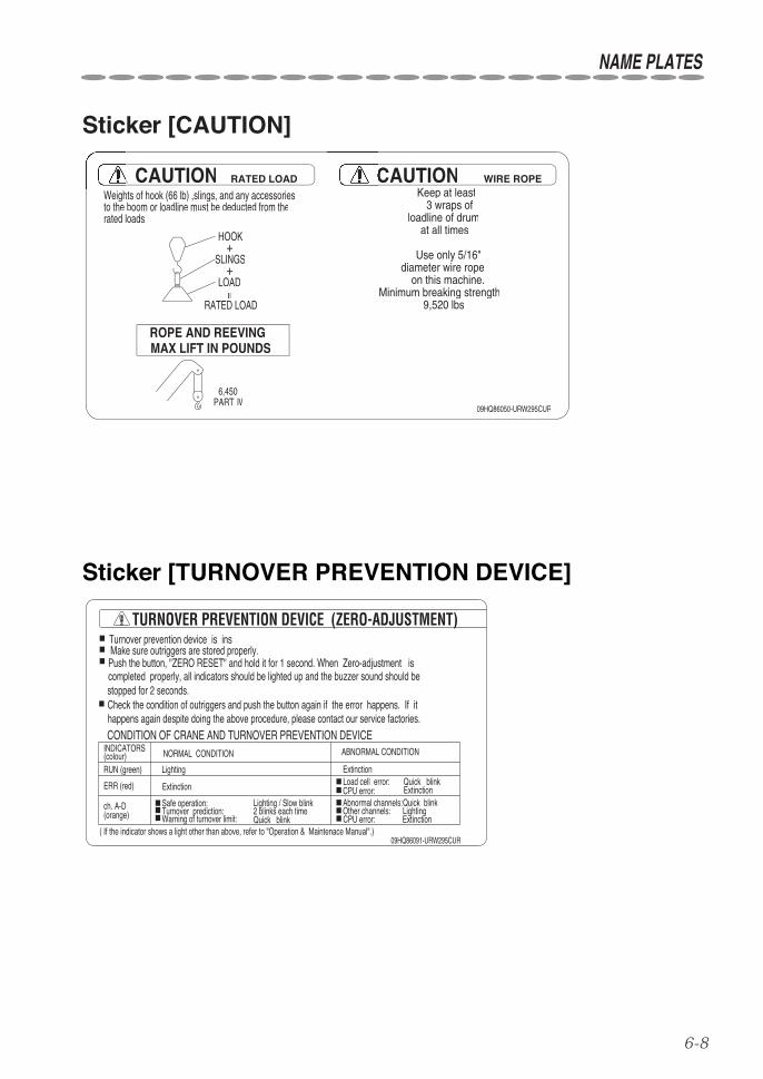
Sticker [CAUTION]
9,520 lbs
09HQ86050-URW295CUR
MAX LIFT IN POUNDSROPE AND REEVING
Weights of hook (66 lb) ,slings, and any accessories
Minimum breaking strengthon this machine.
diameter wire ropeUse only 5/16"
at all timesloadline of drum
3 wraps ofKeep at least
6,450PARTⅣ
CAUTION WIRE ROPE
HOOK
rated loads.to the boom or loadline must be deducted from the
RATED LOADCAUTION
=
+
RATED LOAD
LOAD
+SLINGS
Sticker [TURNOVER PREVENTION DEVICE]
( If the indicator shows a light other than above, refer to "Operation & Maintenace Manual".)09HQ86091-URW295CUR
Turnover prevention device is ins
completed properly, all indicators should be lighted up and the buzzer sound should be
Check the condition of outriggers and push the button again if the error happens. If it
Push the button, "ZERO RESET" and hold it for 1 second. When Zero-adjustment is
happens again despite doing the above procedure, please contact our service factories.
stopped for 2 seconds.
Make sure outriggers are stored properly.■
CONDITION OF CRANE AND TURNOVER PREVENTION DEVICE
TURNOVER PREVENTION DEVICE (ZERO-ADJUSTMENT)
Quick blink
Load cell error:
ABNORMAL CONDITION
2 blinks each time
NORMAL CONDITION
Quick blink
Quick blink
Lighting / Slow blinkTurnover prediction:Warning of turnover limit:
ExtinctionCPU error:
ExtinctionCPU error:LightingOther channels:
Abnormal channels:Safe operation:
■
■■■
(orange)ch. A-D
■■ERR (red)
■■■
RUN (green)(colour)INDICATORS
ExtinctionLighting
Extinction
■
■

7-1
qExtension and spread of outriggers
7. DEFINITION OF TERMS
12.8
ft(3
910m
m)
12.9
ft(3
935m
m)
12.7ft(3885mm)
55°
55°
50°
50°
2in. (50mm)
Slewing center
Position of pin
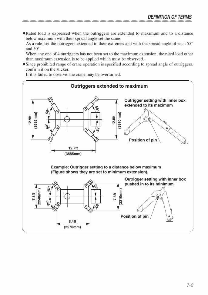
Outrigger setting with inner box extended to its extreme
The figure above shows that outriggers are extended to their extremes.Carry out operation by making the crane level on a flat and solid ground with the outriggersextended to their extremes, and with the crane body raised by approx. 2in. (50mm) above theground.
7-2
DEFINITION OF TERMS
♦Rated load is expressed when the outriggers are extended to maximum and to a distancebelow maximum with their spread angle set the same.As a rule, set the outriggers extended to their extremes and with the spread angle of each 55°and 50°.When any one of 4 outriggers has not been set to the maximum extension, the rated load otherthan maximum extension is to be applied which must be observed.
♦Since prohibited range of crane operation is specified according to spread angle of outriggers,confirm it on the sticker.If it is failed to observe, the crane may be overturned.
12.9
ft
(393
5mm
)
55°55°
50°
50° 12
.8ft
(391
0mm
)
12.7ft
(3885mm)
8.4ft
(2570mm)
7.3f
t
(224
0mm
)
7.6f
t
(231
0mm
)
55°55°
50°
50°
Example: Outrigger setting to a distance below maximum (Figure shows they are set to minimum extension).
Position of pin
Outriggers extended to maximum
Outrigger setting with inner box extended to its maximum
Position of pin
Outrigger setting with inner box pushed in to its minimum
7-3
DEFINITION OF TERMS
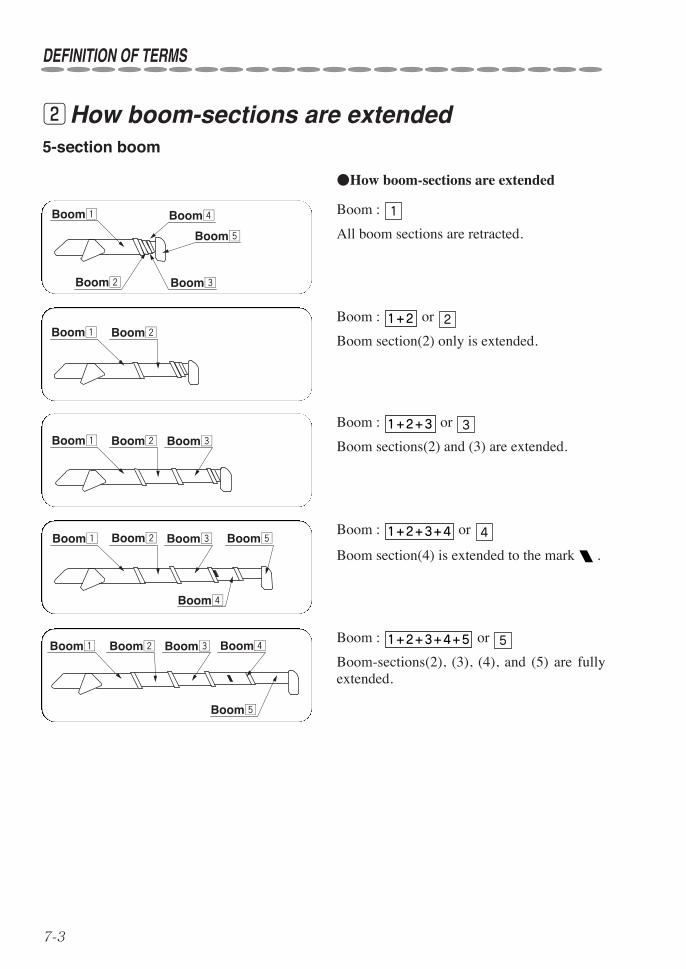
wHow boom-sections are extended
Boom :
All boom sections are retracted.
1
Boom : or
Boom section(2) only is extended.
21+2
●How boom-sections are extended
Boom : or
Boom section(4) is extended to the mark .
41+2+3+4
Boom : or
Boom-sections(2), (3), (4), and (5) are fullyextended.
51+2+3+4+5
Boom : or
Boom sections(2) and (3) are extended.
31+2+3
5-section boom
Boom¡
Boom£Boom™
Boom¢
Boom∞
Boom¡ Boom™
Boom¡ Boom£Boom™
Boom¡ Boom£Boom™
Boom¢
Boom∞
Boom¡ Boom£Boom™ Boom¢
Boom∞
7-4
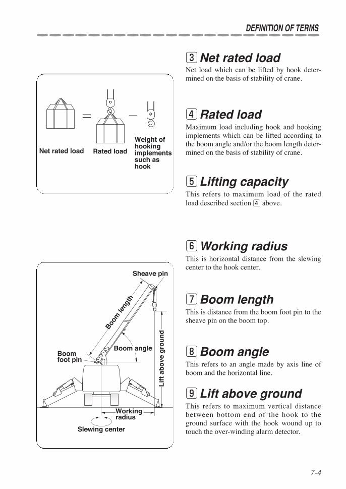
eNet rated loadNet load which can be lifted by hook deter-mined on the basis of stability of crane.
Net rated load Rated load
Weight of hooking implements such as hook
DEFINITION OF TERMS
rRated loadMaximum load including hook and hookingimplements which can be lifted according tothe boom angle and/or the boom length deter-mined on the basis of stability of crane.
tLifting capacityThis refers to maximum load of the ratedload described section r above.
yWorking radiusThis is horizontal distance from the slewingcenter to the hook center.
uBoom lengthThis is distance from the boom foot pin to thesheave pin on the boom top.
iBoom angleThis refers to an angle made by axis line ofboom and the horizontal line.
Lif
t ab
ove
gro
un
d
Working radius
Boom angle
Sheave pin
Boom foot pin
Slewing center
Boom
leng
th
oLift above groundThis refers to maximum vertical distancebetween bottom end of the hook to theground surface with the hook wound up totouch the over-winding alarm detector.

8-1
8. HOW TO REFER TO WORKING RANGE CHART AND RATED LOAD CHART
60°
302515105
5
10
15
25
30
35
BOOM ANGLE
OF HOOKLIFT
OF HOOKLIFT
OF HOOKLIFT
OF HOOKLIFT
OF HOOKLIFT
0°
10°
20°
30°
40°
50°
70°78°
20
020
BOOM LENGTHft
8.30ft
13.37ft
18.41ftft
23.39 28.3854321
LIFT
ING
HE
IGH
T(ft
)
NOTE: The above chart shows the figures withoutdeflection of boom under no-load condition.
WORKING RADIUS (ft)
WORKING RANGE CHART
qWorking range chartThe chart shows the relation among boomlength and working radius, boom angle, andlift above ground.
Boo
mle
ngth
A
B
Working radius
Boom angle
Lift above ground (H)
Working radius with a cargo hoisted
Working radius before hoisting cargo
These charts are stuck in front of crane operation levers and how to refer to charts is illustratedas follows:
Although the point-A and the point-B followthe tracks along the same working radius, thepoint-A refers to the boom angle and thepoint-B the lift above ground.
The working range chart does not incorporateany shift due to deflection of boom.Keep in mind that the actual working radiusis somewhat extended due to boom deflectionwhen a cargo is being hoisted.

8-2
RATED LOADS
(lbs)
(lbs)
(lbs)
(lbs)
BOOM SECTION
BOOM SECTION
BOOM SECTION
BOOM SECTION
130180220300380420530600700850350440500590700750920105012801280
25.023.021.019.018.016.015.0
200660
280850
3701000
4501100
5101200
6001350
7501750
8001950
10001950
11.010.08.07.06.05.04.53.0
7.0 8.0 9.5 10.0 11.0 14.0 15.0
11.0 13.0 15.0 16.0 17.0 18.0 20.0
WORKING RADIUS(ft)
WORKING RADIUS(ft)
WORKING RADIUS(ft)
WORKING RADIUS(ft)
NOT MAX EXT.OUTRIGGERS
LOADRATED
OUTRIGGERSMAX EXT.
NOT MAX EXT.OUTRIGGERS
LOADRATED
OUTRIGGERSMAX EXT.
NOT MAX EXT.OUTRIGGERS
LOADRATED
OUTRIGGERSMAX EXT.
17.62
22.61
12.58
13.512.5
12.5
30055060085010001150125015501850100014501650215024502750305030503050
60095011001600225031504450445020002450285038004350495058506450
44506450
1+2+3+4+5
1+2+3+4
1+2+3
1+21
NOT MAX EXT.OUTRIGGERS
LOADRATED
OUTRIGGERSMAX EXT.
12.0
27.59
wRated load chartThe chart shows maximum load which can be hoisted up for every combination of boom-sec-tions to be extended for each working radius.
HOW TO REFER TO WORKING RANGE CHART AND RATED LOAD CHART
★The chart shows hoisting capacity when the crane is set up level withthe outriggers extended and the data are based on actual workingradius by incorporating shift due to deflection of the boom underloaded.
★The rated loads specified above are based on strength of the craneand stability of the crane.Be sure to check the chart for the rated load as it is to be changedaccording to how far the outriggers are extended.
★This chart shows the rated load including load handling equipmentsuch as slings, buckets, hook blocks, etc. and the weight of materialbeing handled. The weight of the load handling equipment must bededucted from rated load rating to determine how much payload youcan left.
CAUTION

9-1
9. DESCRIPTION OF EACH CONTROL DEVICE
qOverwinding alarm♦1. Function of overwinding alarmThe device automatically makes an alarmsound to warn that the wire ropes are beingover-wound when the hook comes close tothe boom top.
1 Turn ON the over-winding alarm switchbefore starting crane operation.
If the alarm sounds while the hook is beinghoisted or the boom is being extended, stopthe crane operation immediately and lowerthe hook or retract the boom.
2 Turn the alarm switch OFF after thecrane work has been completed.
♦2. Operating procedures
★When the over-winding alarm switch is turned OFF, over-windingalarm will not function even if the hook is being overwound.Be sure to turn the switch ON before starting crane work and check thatthe alarm sounds every time when the weight for over-winding alarm islifted up to the detector.
★Since the length of wire rope hanging the weight is specified by lawsand regulations concerned, do not make it short at random.
★The alarm sounds even if any of electric wires connected to the over-winding detector at the boom top is broken.Ask an authorized UNIC service station for repair.
ON
OFF
Over-winding alarm switch
Cord reel
Overwinding detector
Weight for over-winding alarm
CAUTION
9-2
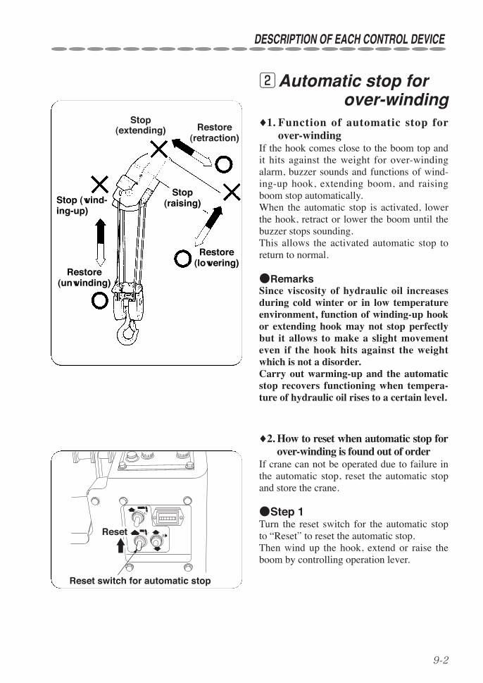
wAutomatic stop for over-winding
♦1. Function of automatic stop forover-winding
If the hook comes close to the boom top andit hits against the weight for over-windingalarm, buzzer sounds and functions of wind-ing-up hook, extending boom, and raisingboom stop automatically.When the automatic stop is activated, lowerthe hook, retract or lower the boom until thebuzzer stops sounding.This allows the activated automatic stop toreturn to normal.
●RemarksSince viscosity of hydraulic oil increasesduring cold winter or in low temperatureenvironment, function of winding-up hookor extending hook may not stop perfectlybut it allows to make a slight movementeven if the hook hits against the weightwhich is not a disorder.Carry out warming-up and the automaticstop recovers functioning when tempera-ture of hydraulic oil rises to a certain level.
DESCRIPTION OF EACH CONTROL DEVICE
Stop(extending) Restore
(retraction)
Stop(raising)
Restore(lowering)
Restore(unwinding)
Stop (wind-ing-up)
Reset
Reset switch for automatic stop
♦2. How to reset when automatic stop forover-winding is found out of order
If crane can not be operated due to failure inthe automatic stop, reset the automatic stopand store the crane.
●Step 1Turn the reset switch for the automatic stopto “Reset” to reset the automatic stop.Then wind up the hook, extend or raise theboom by controlling operation lever.

9-3
STAGE
STAGE
STAGE
STAGE
STAGE
BOOM LENGTH
& ANGLEBOOM RADIUS
PointerScale
(Side of boom)
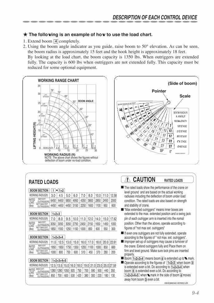
eBoom angle chart The chart reads the working radius corre-sponding to extended length of boom and itsangle.♦1. Working radiusThe value to which the needle points on thescale of meter is the working radius in eachcombination of boom-sections being extend-ed.
♦2. Boom angleDeflection of the needle on the angle scalereads the boom angle.
DESCRIPTION OF EACH CONTROL DEVICE
★ Use a proper scale bandaccording to boom-sectionsbeing extended.
CAUTION
9-4
DESCRIPTION OF EACH CONTROL DEVICE
60°
302515105
5
10
15
25
30
35
BOOM ANGLE
OF HOOKLIFT
OF HOOKLIFT
OF HOOKLIFT
OF HOOKLIFT
OF HOOKLIFT
0°
10°
20°
30°
40°
50°
70°78°
20
020
BOOM LENGTHft
8.30ft
13.37ft
18.41ftft
23.39 28.3854321
LIFT
ING
HE
IGH
T(ft
)
NOTE: The above chart shows the figures withoutdeflection of boom under no-load condition.
WORKING RADIUS (ft)
WORKING RANGE CHART
STAGE
STAGE
STAGE
STAGE
STAGE
BOOM LENGTH
& ANGLEBOOM RADIUS
PointerScale
(Side of boom)
RATED LOADS RATED LOADS
(lbs)
(lbs)
(lbs)
(lbs)
09HQ86040-W295CUR
BOOM SECTION
BOOM SECTION
BOOM SECTION
BOOM SECTION
130180220300380420530600700850350440500590700750920105012801280
25.023.021.019.018.016.015.0
200660
280850
3701000
4501100
5101200
6001350
7501750
8001950
10001950
11.010.08.07.06.05.04.53.0
7.0 8.0 9.5 10.0 11.0 14.0 15.0
11.0 13.0 15.0 16.0 17.0 18.0 20.0
properly.firm and level ground. Make sure lock pins are inserted
If even one outriggers are not fully extended, operatefigures of "not max ext. outriggers"position. Other than the above, operate according topin of each outrigger arm is inserted into the nomalextended to the max. extended position and a swing jack"Max extended outriggers" means inner boxes are
WORKING RADIUS(ft)
WORKING RADIUS(ft)
WORKING RADIUS(ft)
WORKING RADIUS(ft)
NOT MAX EXT.OUTRIGGERS
LOADRATED
OUTRIGGERSMAX EXT.
NOT MAX EXT.OUTRIGGERS
LOADRATED
OUTRIGGERSMAX EXT.
NOT MAX EXT.OUTRIGGERS
LOADRATED
OUTRIGGERSMAX EXT.
17.62
22.61
12.58
13.512.5
12.5
30055060085010001150125015501850100014501650215024502750305030503050
60095011001600225031504450445020002450285038004350495058506450
44506450
1+2+3+4+5
1+2+3+4
1+2+3
1+21
NOT MAX EXT.OUTRIGGERS
LOADRATED
OUTRIGGERSMAX EXT.
CAUTION
and stability of crane.condition. The rated loads are also based on strengthradiuses including the deflection of boom under loadlevel ground and are based on the actual working
4
4
away from boom even a bit. when mark in the side of boom moves1+2+3+4+5
boom is extended even a bit. Do according to1+2+3+4
4
Operate according to the figures of when boom 31+2+3is extended even a bit. Do according to when
Boom means boom is extended up to mark.1+2+3+4
3
the crane. Extend outriggers fully and Place them onImproper set-up of outriggers may cause a turnover ofaccording to the figures of " not max. ext. outriggers".
The rated loads show the performance of the crane on
12.0
27.59
★ The following is an example of how to use the load chart.1. Extend boom completely.2. Using the boom angle indicator as you guide, raise boom to 50° elevation. As can be seen,
the boom radius is approximately 15 feet and the hook height is approximately 18 feet.By looking at the load chart, the boom capacity is 1350 lbs. When outriggers are extendedfully. The capacity is 600 lbs when outriggers are not extended fully. This capacity must bereduced for some optional equipment.
4

DESCRIPTION OF EACH CONTROL DEVICE
9-5
Working radius with a cargo hoisted
Working radius before hoisting cargo ★When a boom is extended to
halfway, use the rated load withthe boom concerned fullyextended in order to secure safe-ty.●When boom-section is
extended from boom-section, take the rated load for
boom (2450 lbs in theexample shown above).●When boom-section is
extended from boom-section, take the rated load for
boom (1350 lbs inthe example shown above).
★ Since the working radiusincreases due to deflection of theboom when a cargo starts to belifted up , set the boom angle sothat the hook comes to some-what inner side.
1+2+3+4
3
4
1+2+3
2
3
CAUTION

9-6
DESCRIPTION OF EACH CONTROL DEVICE
♦How to refer to hoisting capacity when outriggers are extended to minimum or tohalfway.
As a general rule, the outriggers are to be extended to their extremes.If it is forced to operate the crane with the outriggers extended to minimum or to halfway, oper-ate the crane in accordance with instructions shown below.
1. Find the working radius.2. The rated load is to be obtained from the data shown in the “not max ext. outriggers” accord-ing to how boom-sections are extended.
●When operated with the working radius of 11ft ,with the extended boom configuration of, and with outriggers extended to halfway or to minimum, take 950 lbs.
●When operated with the working radius of 10ft, with the extended boom configuration of, and with outriggers extended to halfway or to minimum, take 1150 lbs.1+2+3
1+2
RATED LOADS
(lbs)
(lbs)
BOOM SECTION
BOOM SECTION
11.010.08.07.06.05.04.53.0
7.0 8.0 9.5 10.0 11.0 14.0 15.0WORKING RADIUS(ft)
WORKING RADIUS(ft)
NOT MAX EXT.OUTRIGGERS
LOADRATED
OUTRIGGERSMAX EXT.
17.62
12.58
30055060085010001150125015501850100014501650215024502750305030503050
60095011001600225031504450445020002450285038004350495058506450
44506450
1+2+3
1+21
NOT MAX EXT.OUTRIGGERS
LOADRATED
OUTRIGGERSMAX EXT.
12.0
★When the outriggers are extended to minimum or halfway, operate thecrane according to capacity obtained from “not max extended outrig-gers” on the chart of rated load.
★The load indicator can not be used when the outriggers are extendedto minimum or to halfway.
CAUTION
★It is important that you know the weight of any material that youattempt to handle.This can be determined by use of a dynamometer or scales.
Note: The rated load chart shows the rated load including load handlingequipment such as slings, buckets, hook block, etc., and theweight of material being handled.The weight of load handling equipment must be deducted fromthe rated load rating to determine how much pay load you can lift.
WARNING

9-7
DESCRIPTION OF EACH CONTROL DEVICE
Warning horn switch
rWarning hornBefore lifting up the cargo, depress the warn-ing horn switch on the crawler panel to givewarning sound to those who have enteredwithin slewing range during crane operation,or to workers in charge of slinging work nearthe cargo or in a course where the cargo maypass along.Depress the switch button to give warningsound.
Warning horn switch

9-8
Automatic stop for leaving minimum wire rope (with wire rope retaining roller)
yAutomatic stop forleaving minimumwire rope (with wirerope retaining roller)
This is a devise to restrict slackening of wirerope on the drum.The device prevents the rope on the drumfrom slackening when winding up and downthe hook or making it an abrupt stop andwhen the hook is lowered to the ground.In addition, it allows to stop unwinding auto-matically when remaining wire ropes on thedrum come close to 3 turns so that the ropecan not be unwound further.
DESCRIPTION OF EACH CONTROL DEVICE
Hook safety latch
tHook safety latchThe mechanism is to prevent slinging wirerope from being disengaged out of the hook.

9-9
DESCRIPTION OF EACH CONTROL DEVICE
Beep・・・
uSpecifications on turnover prevention device
★Observe the caution to secure safety.Failure to observe the cautions may invite trouble or serious accident.Be sure to carry out the inspection in particular before starting opera-tion.
1 Carry out careful inspection before oper-ation, and daily and periodical inspection
to confirm that the turn over preventiondevice functions properly.
2 The turn over prevention device is asafety device that allows to slow down
operating speed gradually while making anintermittent warning sound when the groundreaction against the outrigger located onopposite side of the boom decreases to thespecified level due to increase of cranemoment.If the reaction force of the outrigger decreas-es further, the warning changes to continuoussound and the crane makes an automatic stop.Crane functions to be stopped are : windingup hook, extending boom, and loweringboom.Check the turn over prevention device forproper operation before starting the craneoperation.
3 If the crane is operated via radio-con-troller, operate it within the range where
the alarm sound can be heard.
4 Over-loaded operation is strictly prohib-ited.
The turn over prevention device is not adevice for preventing overload. It is the principle that you should persistentlyobserve the operation within rated load.Do not put too much confidence on thedevice.Leaning of the crane due to swing of a liftedcargo or parking on unleveled ground mayallow the crane to be overturned.
WARNING
9-10
DESCRIPTION OF EACH CONTROL DEVICE
5 If an alarm sounds intermittently due todecrease of ground reaction against out-
riggers, operating the crane to safer side.If the reaction force of the outrigger decreas-es further, the crane makes an automatic stop.In this case, faster operating speed can makethe crane to be overturned to which must payattention.
6 Observe that the crane shall not be oper-ated within the prohibited range in
extending outriggers.The turn over prevention device will notfunction safely when the crane is operatedwithin the prohibited range.
7 Keep the “ON-OFF” switch for alarmbuzzer turning ON unless there is any
special reason.
8 As a rule, set up the crane on a flat andsolid ground to operate it with the out-
riggers extended to their extremes, with thetruck kept level, and with the rubber crawlerlifted up by approx. 2in. (50mm) above theground.
9-11
DESCRIPTION OF EACH CONTROL DEVICE
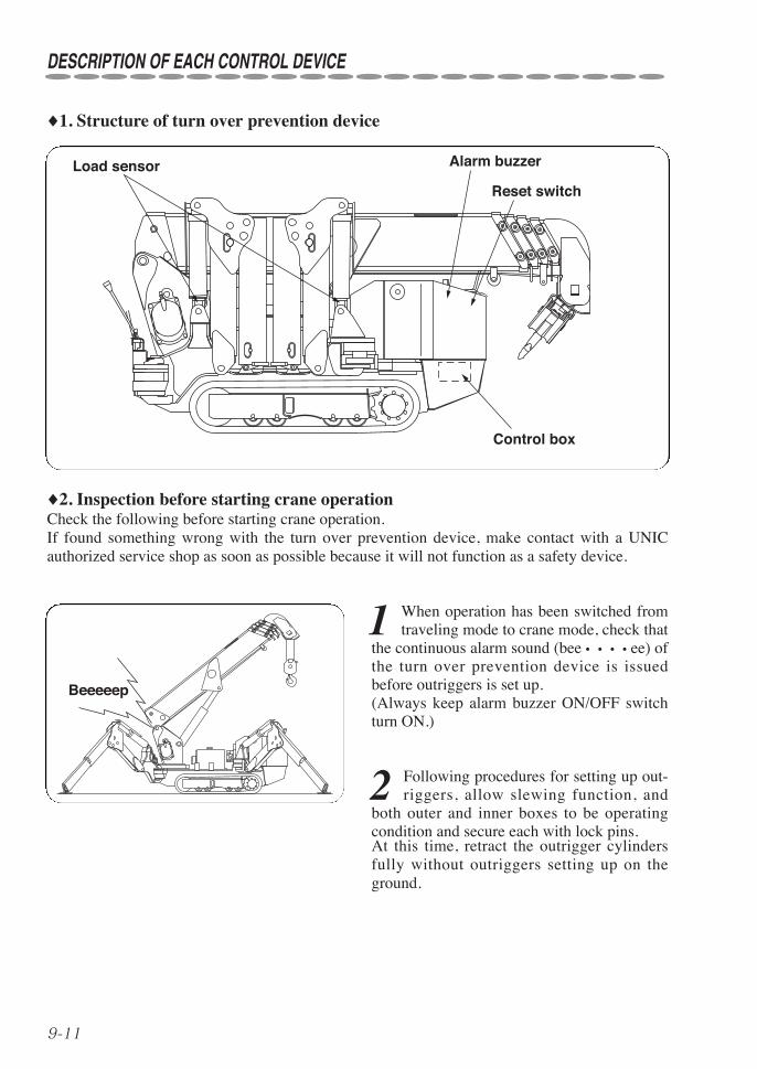
♦1. Structure of turn over prevention device
Control box
Load sensor Alarm buzzer
Reset switch
♦2. Inspection before starting crane operationCheck the following before starting crane operation.If found something wrong with the turn over prevention device, make contact with a UNICauthorized service shop as soon as possible because it will not function as a safety device.
1 When operation has been switched fromtraveling mode to crane mode, check that
the continuous alarm sound (bee • • • • ee) ofthe turn over prevention device is issuedbefore outriggers is set up.(Always keep alarm buzzer ON/OFF switchturn ON.)
2 Following procedures for setting up out-riggers, allow slewing function, and
both outer and inner boxes to be operatingcondition and secure each with lock pins.At this time, retract the outrigger cylindersfully without outriggers setting up on theground.
Beeeeep
9-12
DESCRIPTION OF EACH CONTROL DEVICE
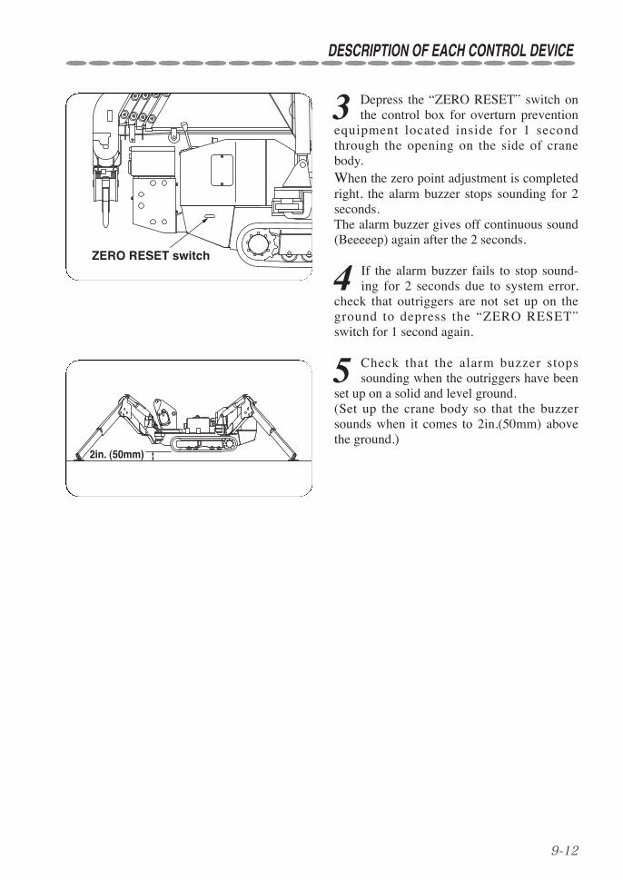
3 Depress the “ZERO RESET” switch onthe control box for overturn prevention
equipment located inside for 1 secondthrough the opening on the side of cranebody. When the zero point adjustment is completedright, the alarm buzzer stops sounding for 2seconds.The alarm buzzer gives off continuous sound(Beeeeep) again after the 2 seconds.
4 If the alarm buzzer fails to stop sound-ing for 2 seconds due to system error,
check that outriggers are not set up on theground to depress the “ZERO RESET”switch for 1 second again.
5 Check that the alarm buzzer stopssounding when the outriggers have been
set up on a solid and level ground. (Set up the crane body so that the buzzersounds when it comes to 2in.(50mm) abovethe ground.)
ZERO RESET switch
2in. (50mm)
Ch. A (orange)
9-13
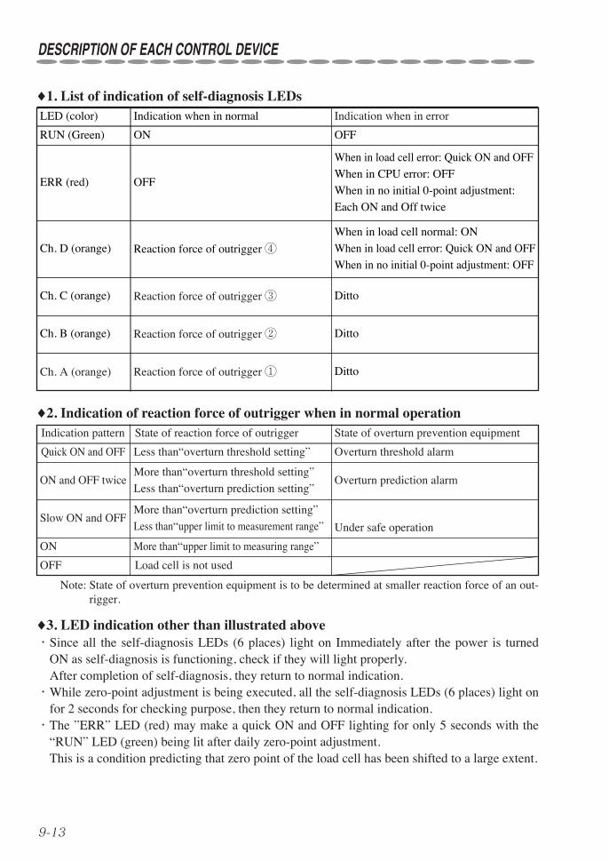
♦1. List of indication of self-diagnosis LEDs
♦2. Indication of reaction force of outrigger when in normal operation
♦3. LED indication other than illustrated above・Since all the self-diagnosis LEDs (6 places) light on Immediately after the power is turned
ON as self-diagnosis is functioning, check if they will light properly.After completion of self-diagnosis, they return to normal indication.
・While zero-point adjustment is being executed, all the self-diagnosis LEDs (6 places) light onfor 2 seconds for checking purpose, then they return to normal indication.
・The ”ERR” LED (red) may make a quick ON and OFF lighting for only 5 seconds with the“RUN” LED (green) being lit after daily zero-point adjustment.This is a condition predicting that zero point of the load cell has been shifted to a large extent.
Note: State of overturn prevention equipment is to be determined at smaller reaction force of an out-rigger.
Indication pattern
Quick ON and OFF
ON and OFF twice
Slow ON and OFF
ON
OFF
State of reaction force of outrigger
Less than“overturn threshold setting”
More than“overturn threshold setting”
Less than“overturn prediction setting”
More than“overturn prediction setting”
Less than“upper limit to measurement range”
More than“upper limit to measuring range”
Load cell is not used
State of overturn prevention equipment
Overturn threshold alarm
Overturn prediction alarm
Under safe operation
LED (color)
RUN (Green)
ERR (red)
Ch. D (orange)
Ch. C (orange)
Ch. B (orange)
Indication when in normal
ON
OFF
Reaction force of outrigger ④
Reaction force of outrigger ③
Reaction force of outrigger ②
Reaction force of outrigger ①
Indication when in error
OFF
When in load cell error: Quick ON and OFF
When in CPU error: OFF
When in no initial 0-point adjustment:
Each ON and Off twice
When in load cell normal: ON
When in load cell error: Quick ON and OFF
When in no initial 0-point adjustment: OFF
Ditto
Ditto
Ditto
DESCRIPTION OF EACH CONTROL DEVICE
9-14
DESCRIPTION OF EACH CONTROL DEVICE
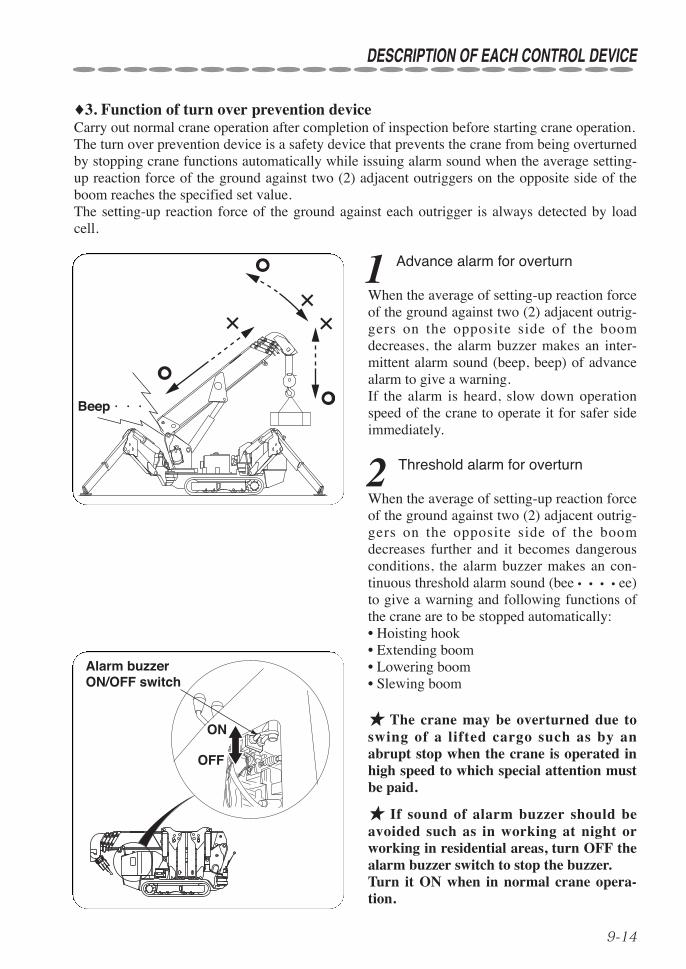
♦3. Function of turn over prevention deviceCarry out normal crane operation after completion of inspection before starting crane operation.The turn over prevention device is a safety device that prevents the crane from being overturnedby stopping crane functions automatically while issuing alarm sound when the average setting-up reaction force of the ground against two (2) adjacent outriggers on the opposite side of theboom reaches the specified set value.The setting-up reaction force of the ground against each outrigger is always detected by loadcell.
Beep・・・
1 Advance alarm for overturn
When the average of setting-up reaction forceof the ground against two (2) adjacent outrig-gers on the opposite side of the boomdecreases, the alarm buzzer makes an inter-mittent alarm sound (beep, beep) of advancealarm to give a warning.If the alarm is heard, slow down operationspeed of the crane to operate it for safer sideimmediately.
2 Threshold alarm for overturn
When the average of setting-up reaction forceof the ground against two (2) adjacent outrig-gers on the opposite side of the boomdecreases further and it becomes dangerousconditions, the alarm buzzer makes an con-tinuous threshold alarm sound (bee • • • • ee)to give a warning and following functions ofthe crane are to be stopped automatically:• Hoisting hook• Extending boom• Lowering boom• Slewing boom
★ The crane may be overturned due toswing of a lifted cargo such as by anabrupt stop when the crane is operated inhigh speed to which special attention mustbe paid.
★ If sound of alarm buzzer should beavoided such as in working at night orworking in residential areas, turn OFF thealarm buzzer switch to stop the buzzer.Turn it ON when in normal crane opera-tion.
ON
OFF
Alarm buzzerON/OFF switch
9-15
DESCRIPTION OF EACH CONTROL DEVICE
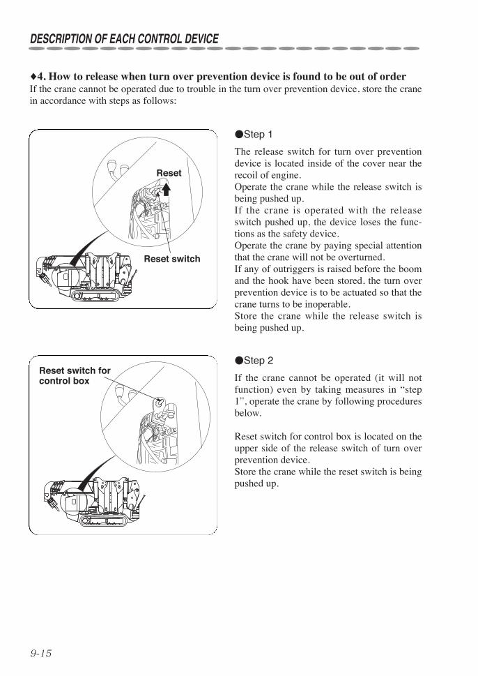
♦4. How to release when turn over prevention device is found to be out of orderIf the crane cannot be operated due to trouble in the turn over prevention device, store the cranein accordance with steps as follows:
Reset
Reset switch
Reset switch for control box
●Step 1
The release switch for turn over preventiondevice is located inside of the cover near therecoil of engine.Operate the crane while the release switch isbeing pushed up.If the crane is operated with the releaseswitch pushed up, the device loses the func-tions as the safety device.Operate the crane by paying special attentionthat the crane will not be overturned.If any of outriggers is raised before the boomand the hook have been stored, the turn overprevention device is to be actuated so that thecrane turns to be inoperable.Store the crane while the release switch isbeing pushed up.
●Step 2
If the crane cannot be operated (it will notfunction) even by taking measures in “step1”, operate the crane by following proceduresbelow.
Reset switch for control box is located on theupper side of the release switch of turn overprevention device.Store the crane while the reset switch is beingpushed up.

9-16
DESCRIPTION OF EACH CONTROL DEVICE
★When the reset switch is being pushed, the crane cannot be operatedthrough radio remote control but it can only be operated manually.In addition, adjust acceleration of the engine manually as the automaticacceleration also becomes impossible when the reset switch is beingpushed.
★Since this is a temporary measures in an emergency, be sure torepair it at a UNIC service shop after the crane has been stored.
CAUTION
●Step 3
If the crane cannot be operated (it will notfunction) by taking measures in “step 1” and“step 2” above, operate the crane by follow-ing procedures below.
Unfasten the hexagon nut on the side ofunload valve attached to underside of thecontrol valves to tighten up the set bolt beinglocked until it comes to a stop.Since this allows the crane to be operated,store the crane by controlling levers.
(Underside of control valve)
Set bolt Hexagon nut
★Since this is a temporary measures in an emergency, be sure torepair it at a UNIC service shop after the crane has been stored.
CAUTION

9-17
DESCRIPTION OF EACH CONTROL DEVICE
♦5. Caution plates in detail
★Always keep the stickers clean so that they can be read easily.★ If any of the stickers has come off, stick it again or replace it with
new sticker.★When ordering stickers, specify the part number shown at the bot-
tom-right of the sticker concerned.
CAUTION
CAUTIONS Be sure to perform inspection (pre-start inspection) before starting operationsto make sure that this device works.Overload is strictly prohibited. This device is designed for operations withinthe rated load in principle and not for prevention of overload. Do not havetoo much confidence in this device. If the crane inclines due to swing of loador grounding on rough terrain, it could turnover.As ground reaction force is lowering, a warning indicating that turnover isclose is given. Slow down the operating speed and immediately operate the craneto a safe side. If ground reaction force further lowers, the following cranemovements stop automatically. In this case, extreme care must be used becausethe crane may turnover due to swing of load if the crane speed is fast.
○Hoisting of hook ○Extension of boom ○Lowering of boom ○Swing to right and left
TURN OVER PREVENTION DEVICE
10-1
10. HOW TO OPERATE CARRIER
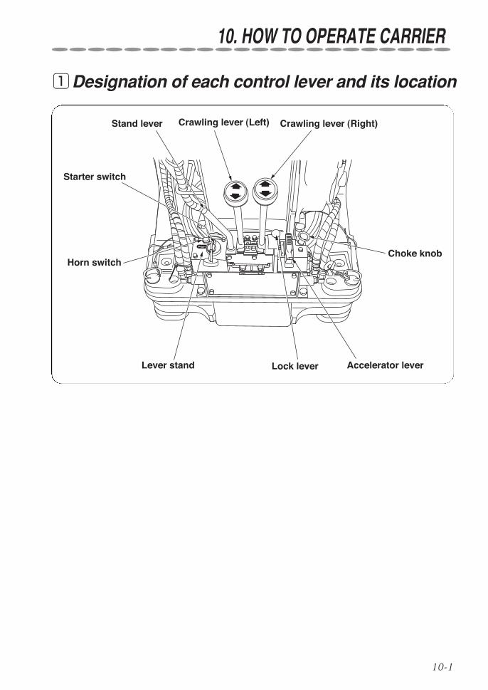
qDesignation of each control lever and its location
Accelerator lever
Stand lever Crawling lever (Left) Crawling lever (Right)
Starter switch
Horn switchChoke knob
Lever stand Lock lever

10-2
HOW TO OPERATE CARRIER
1 Shift the crawling lever stand to ”Travel”position.
2 Make sure that both crawling levers (leftand right) are at their neutral positions.
3 Confirm that the machine is at crawlingposture.
• Boom is lowered to its extreme.• Outriggers are stored.• Hook is stored.
TRAVEL LEVER STAND
LOCK LEVER
STAND LEVER
TRAVEL LEVER
CRANE OPERATION POSITION TRAVEL POSITION STOWAGE POSITION
wPreparation before operation
★Ventilate well when starting the engine in a small limited area orindoors.
★Do not start the engine from the outside of the operator’s seat.
★Confirm the safety around the crane working site before starting theengine.
★Heavy-duty operation of the crane during an initial period after thestart of operation may deteriorate its performance in a shorter time.Take approximately 100 hours after the start of operation as a breakingin period during which abrupt start and acceleration, and continuousoperation under heavy load must be avoided.
WARNING
CAUTION
Open
4 Open the fuel cock.
5 Raise engine speed to that somewhathigher than idling.
10-3
HOW TO OPERATE CARRIER
eHow to operate
★Do not start the engine by using a auxiliary ignition fluid as it may bein danger of explosion.
★Be sure to repair whenever found anything unusual.
★Be sure to stop the engine before re-fueling.
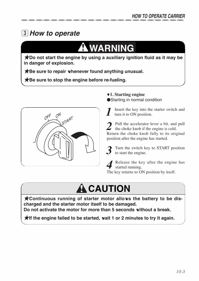
♦1. Starting engine●Starting in normal condition
1 Insert the key into the starter switch andturn it to ON position.
2 Pull the accelerator lever a bit, and pullthe choke knob if the engine is cold.
Return the choke knob fully to its originalposition after the engine has started.
3 Turn the switch key to START positionto start the engine.
4 Release the key after the engine hasstarted running.
The key returns to ON position by itself.
★Continuous running of starter motor allows the battery to be dis-charged and the starter motor itself to be damaged.Do not activate the motor for more than 5 seconds without a break.
★If the engine failed to be started, wait 1 or 2 minutes to try it again.
WARNING
CAUTION
OFF ON
START
10-4
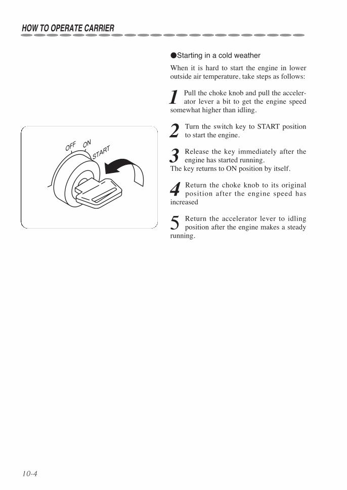
●Starting in a cold weather
When it is hard to start the engine in loweroutside air temperature, take steps as follows:
1 Pull the choke knob and pull the acceler-ator lever a bit to get the engine speed
somewhat higher than idling.
2 Turn the switch key to START positionto start the engine.
3 Release the key immediately after theengine has started running.
The key returns to ON position by itself.
4 Return the choke knob to its originalposition after the engine speed has
increased
5 Return the accelerator lever to idlingposition after the engine makes a steady
running.
OFF ON
START
HOW TO OPERATE CARRIER
10-5
HOW TO OPERATE CARRIER
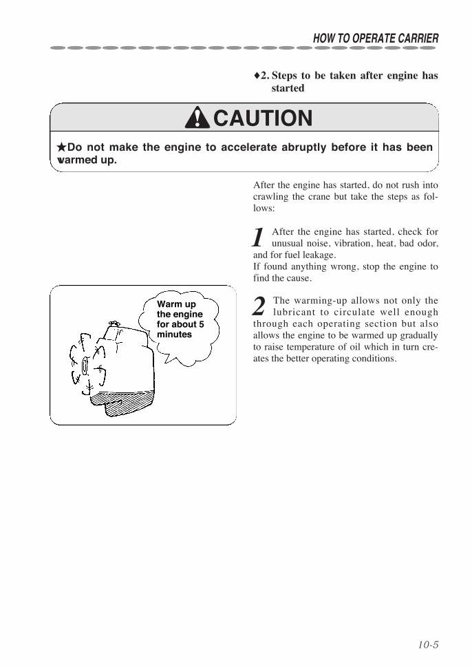
♦2. Steps to be taken after engine hasstarted
★Do not make the engine to accelerate abruptly before it has beenwarmed up.
After the engine has started, do not rush intocrawling the crane but take the steps as fol-lows:
1 After the engine has started, check forunusual noise, vibration, heat, bad odor,
and for fuel leakage.If found anything wrong, stop the engine tofind the cause.
2 The warming-up allows not only thelubricant to circulate well enough
through each operating section but alsoallows the engine to be warmed up graduallyto raise temperature of oil which in turn cre-ates the better operating conditions.
CAUTION
Warm upthe enginefor about 5minutes

10-6
rHow to Crawl
★Start the crane crawling after the safety around the crawler has beenconfirmed and make a sign when starting the crane crawling.★Carry out crawling operation by standing in front of the crawlinglever.★Keep anyone away from the crane.★Do not craw the crane with someone or an object mounted on thecrane.★Arrange those who guide at a place where it may be unsafe and youhave a blind spot.★Crawl the crane as slowly as possible while making a turn.★If crawling backward, watch where it is to be crawl and restrain crawl-ing speed.★Run the crane slowly when making a sharp turn and crawling on arough road.★Before leaving the crane, shift the crawling lever stand to storingposition and stop the engine.★Avoid running over obstacles.If it is unavoidable, crawl at low speed and keep the crane to lean lessthan 10° to the side.★When parking the crane on the street is unavoidable, set up safetydevices such as a sign, a barricade, and a blinking light so that passingof other vehicles and pedestrians may not be disturbed.★Put a pallet against the rubber crawler when parking the crane for along period of time.★Do not park the crane over a place where withered grass or straw,which is flammable. This may cause a fire by heat of exhaust pipe or exhaust fume.★When crawling the crane on a water filled area, observe to crawl itwithin allowable depth of water.Allowable depth: Up to the center of crawling motor or of sprocket.★In case where the machine is forced to turn on the spot (spin turn),be sure to stop the movement of the machine first, allow the engine torun at a low speed to make it turn slowly and gently.An abrupt turning not only damages the rubber crawler badly but alsocauses the machine to bounce from which may invite a very dangeroussituation.
WARNING
HOW TO OPERATE CARRIER
10-7
HOW TO OPERATE CARRIER
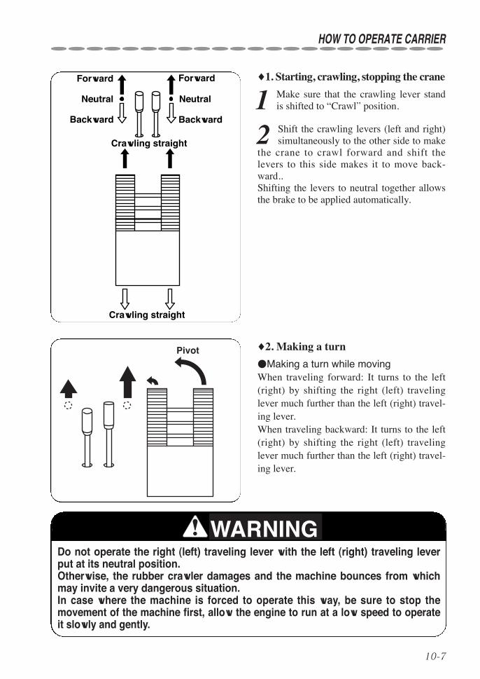
♦1. Starting, crawling, stopping the crane
1 Make sure that the crawling lever standis shifted to “Crawl” position.
2 Shift the crawling levers (left and right)simultaneously to the other side to make
the crane to crawl forward and shift thelevers to this side makes it to move back-ward..Shifting the levers to neutral together allowsthe brake to be applied automatically.
Crawling straight
Forward Forward
Neutral Neutral
Backward Backward
Crawling straight
♦2. Making a turn
●Making a turn while movingWhen traveling forward: It turns to the left(right) by shifting the right (left) travelinglever much further than the left (right) travel-ing lever.When traveling backward: It turns to the left(right) by shifting the right (left) travelinglever much further than the left (right) travel-ing lever.
Pivot
Do not operate the right (left) traveling lever with the left (right) traveling leverput at its neutral position.Otherwise, the rubber crawler damages and the machine bounces from whichmay invite a very dangerous situation.In case where the machine is forced to operate this way, be sure to stop themovement of the machine first, allow the engine to run at a low speed to operateit slowly and gently.
WARNING

10-8
HOW TO OPERATE CARRIER
●Making a turn when the machine is at astandstill
Shifting the traveling levers both to the rightand to the left forward at the same timeallows the machine to turn to the right (left) ifthe left (right) traveling lever is moved muchfurther than the right (left) traveling lever.Shifting the traveling levers both to the rightand to the left backward at the same timeallows the machine to turn to the right (left) ifthe left (right) traveling lever is moved muchfurther than the right (left) traveling lever.
Pivot
Turning it on the spot ●Making a turn on the spot (spin turn)As a rule, do not make the machine to turn onthe spot.In case where the machine is forced to turnon the spot, be sure to stop the movement ofthe machine first and allow the engine to runat a low speed.Shifting the left (right) traveling lever for-ward and the right (left) traveling lever back-ward slowly allows the machine to turn to theright (left) on the spot.
An abrupt turning not only damagesthe rubber crawler badly but alsocauses the machine to bounce fromwhich may invite a very dangeroussituation.
WARNING
Do not operate the right (left) traveling lever with the left (right) traveling leverput at its neutral position.Otherwise, the rubber crawler damages and the machine bounces from whichmay invite a very dangerous situation.In case where the machine is forced to operate this way, be sure to stop themovement of the machine first, allow the engine to run at a low speed to operateit slowly and gently.
WARNING
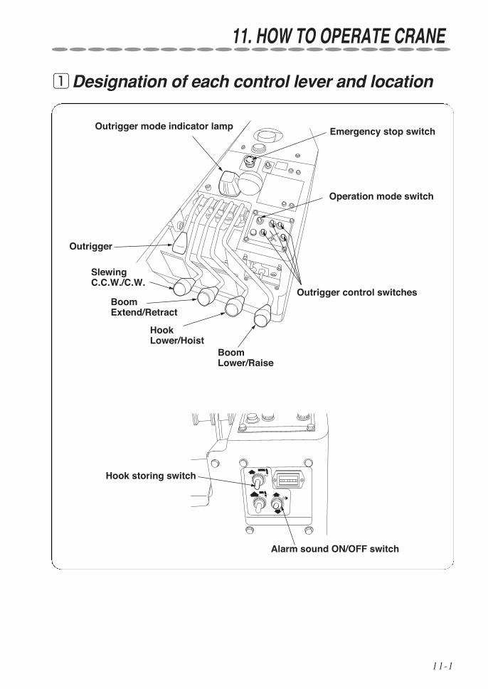
11-1
11. HOW TO OPERATE CRANE
qDesignation of each control lever and location
BoomLower/Raise
Outrigger control switches
Hook storing switch
Emergency stop switch
Alarm sound ON/OFF switch
Outrigger
Operation mode switch
Boom Extend/Retract
Slewing C.C.W./C.W.
Outrigger mode indicator lamp
Hook Lower/Hoist
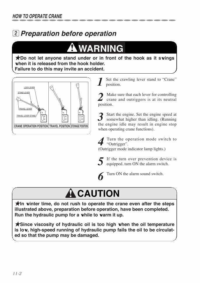
11-2
HOW TO OPERATE CRANE
wPreparation before operation
TRAVEL LEVER STAND
LOCK LEVER
STAND LEVER
TRAVEL LEVER
CRANE OPERATION POSITION TRAVEL POSITION STOWAGE POSITION
★In winter time, do not rush to operate the crane even after the stepsillustrated above, preparation before operation, have been completed.Run the hydraulic pump for a while to warm it up.
★Since viscosity of hydraulic oil is too high when the oil temperatureis low, high-speed running of hydraulic pump fails the oil to be circulat-ed so that the pump may be damaged.
1 Set the crawling lever stand to “Crane”position.
2 Make sure that each lever for controllingcrane and outriggers is at its neutral
position.
3 Start the engine. Set the engine speed atsomewhat higher than idling. (Running
the engine idle may result in engine stopwhen operating crane functions).
4 Turn the operation mode switch to“Outrigger”.
(Outrigger mode indicator lamp lights.)
5 If the turn over prevention device isequipped, turn ON the alarm switch.
6 Turn ON the alarm sound switch.
★Do not let anyone stand under or in front of the hook as it swingswhen it is released from the hook holder.Failure to do this may invite an accident.
WARNING
CAUTION

11-3
HOW TO OPERATE CRANE
eProcedures to set up outriggers
★Crane operation without setting up the outriggers is strictly prohibit-ed.
★Do not operate the crane and extend outrigger cylinders and innerboxes while outriggers have been stored.
★When setting up the outriggers on a rough ground or on a slope, besure to place a support (such as plank, steel plate etc.) under the outrig-ger foot flanges to keep the crane level.In addition, when the crane is to be operated on a soft ground, take thesame measures to prevent the outrigger foot flanges from sinking intothe ground when a cargo is lifted up.Setting up the crane on a ground where it is not solid and firm enoughmay cause it to be overturned.
★Do not put your foot under the outrigger foot flange while outriggersare being extended.It may invite such accident as that the foot may be crushed by the out-rigger.
★Operation with the crane kept leaning makes it unstable when acargo is lifted up.Such operation can cause the outriggers to be damaged and the craneto be overturned.
★The rated load is to be changed according to how far (maximum,halfway, minimum) the outriggers are extended.Be sure to consult the “sticker concerning PROHIBITED AREA OFCRANE OPERATIONS” for the rated load corresponding to each exten-sion.
★In normal crane operation, set up the crane level on a solid and firmground with the outriggers fully extended and lift up the crane body byapprox. 2in (50mm) above the ground.
★When outriggers are extended or being stored, be sure to insert theset pins so that the outriggers may not be rotated unexpectedly.
★When extending outriggers, extend the inner boxes and allow them totouch the ground by using the outrigger cylinders.
★Be sure to touch the outriggers to the ground, as the crane may sinkinto the ground naturally if they are detached away from the ground.
WARNING

11-4
There are four (4) outrigger control switchesand each switch is numbered.Select an outrigger control switch to throw itto desired function and operate the outriggerlever accordingly.
Set up the outriggers as follows:
1 Extract the outrigger set pin and insert itin appropriate place while referring to
the sticker “PROHIBITED RANGE OFCRANE OPERATION”.
2 Remove the lock pin (1) in the arm andhold the knob of outer box firmly to lift
it up. Insert the lock pin and retain it with a stopperpin.
3 Remove the lock pin (2) to pull out theinner box.
Insert the lock pin (2) and retain it with astopper pin.
4 Control each outrigger control lever toadjust that the crane body is raised by
approx. 50mm above the ground and it keepslevel by referring to a level.
HOW TO OPERATE CRANE
①
② ③
④
①
② ③
④
OUTRIGGER
Outrigger operation
Outrigger lever
Outrigger control switches
EXT
RETOUTRIGGER
CRANE
HORN
MODE
OUTRIGGERS
EXT
RET
EXT
RET
EXT
RET
Set pin
Arm
Lock pin (1)
Outer box
Knob
Inner box
Lock pin (2)

11-5
HOW TO OPERATE CRANE
★Insert each set pin securelywhen the outriggers are beingstored and set up on the ground.Insufficient insertion of the setpins allows them to come offwhich in turn may make thecrawler to lose balance causingthe crane to be overturned.
Set pin
WARNING
Lock pin
Stopper pin
Recess
★After the lock pin has beeninserted, be sure to put the stop-per pin in the recess to retain itsecurely.If neglected, the lock pin gradual-ly escapes during crane opera-tion which in turn causes over-turn.

11-6
♦Extension of outriggers and rated load
★Rated load is expressed when the outriggers are extended to maxi-mum and to a distance below maximum with their spread angle set thesame.As a rule, set the outriggers extended to their extremes and with thespread angle of each 55° and 50°.When any one of 4 outriggers has not been set to the maximum exten-sion, “not max ext. outriggers” in “rated loads” is to be applied whichmust be observed.
★Since prohibited range of crane operation is specified according tospread angle of outriggers, confirm it on the sticker.If it is failed to observe, the crane may be overturned.
12.9
ft
(393
5mm
)
55°55°
50°
50° 12
.8ft
(391
0mm
)
12.7ft
(3885mm)
8.4ft
(2570mm)
7.3f
t
(224
0mm
)
7.6f
t
(231
0mm
)
55°55°
50°
50°
Example: Outrigger setting to a distance below maximum (Figure shows they are set to minimum extension).
Position of pin
Outriggers extended to maximum
Outrigger setting with inner box extended to its maximum
Position of pin
Outrigger setting with inner box pushed in to its minimum
WARNING
HOW TO OPERATE CRANE
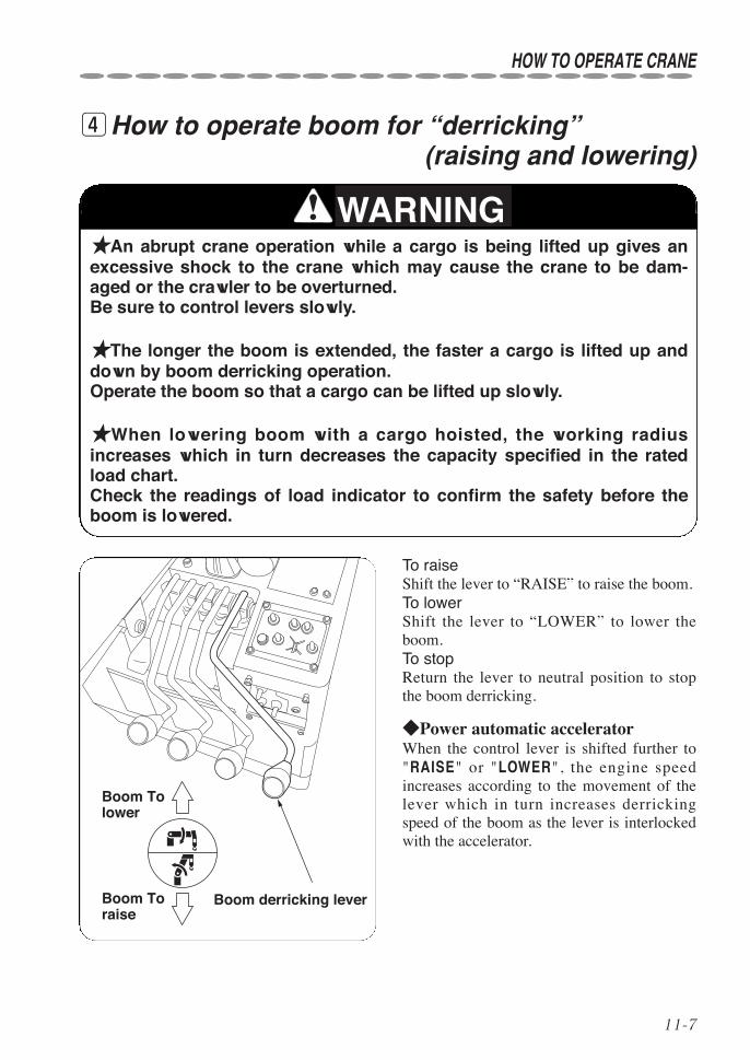
11-7
HOW TO OPERATE CRANE
rHow to operate boom for “derricking” (raising and lowering)
To raiseShift the lever to “RAISE” to raise the boom.To lowerShift the lever to “LOWER” to lower theboom.To stopReturn the lever to neutral position to stopthe boom derricking.
◆Power automatic acceleratorWhen the control lever is shifted further to"RAISE" or "LOWER", the engine speedincreases according to the movement of thelever which in turn increases derrickingspeed of the boom as the lever is interlockedwith the accelerator.
★An abrupt crane operation while a cargo is being lifted up gives anexcessive shock to the crane which may cause the crane to be dam-aged or the crawler to be overturned.Be sure to control levers slowly.
★The longer the boom is extended, the faster a cargo is lifted up anddown by boom derricking operation.Operate the boom so that a cargo can be lifted up slowly.
★When lowering boom with a cargo hoisted, the working radiusincreases which in turn decreases the capacity specified in the ratedload chart.Check the readings of load indicator to confirm the safety before theboom is lowered.
WARNING
Boom derricking leverBoom To raise
Boom To lower

11-8
tHow to hoist and lower the hook
★Pay attention that the hook will not be over-wound.Be sure to turn ON the “alarm sound ON/OFF switch”.
★If the hook hits against the boom top due to being over-wound of thehook, it may cause damage to the wire rope and the sheaves at theboom top and may cause the lifted cargo to fall.
To wind up(raise)Shift the lever to “UP” to raise the hook.To wind down(lower)Shift the lever to “DOWN” to lower thehook..To stopReturn the lever to neutral position to stopthe hook being wound up/down.
◆Power automatic acceleratorWhen the control lever is shifted further to"WIND UP" or to "WIND DOWN", the enginespeed increases according to the movementof the lever which in turn increases hoistingspeed of the hook as the lever is interlockedwith the accelerator.
WARNING
HOW TO OPERATE CRANE
Hook hoisting/lowering lever
Hook To wind up
Hook To wind down
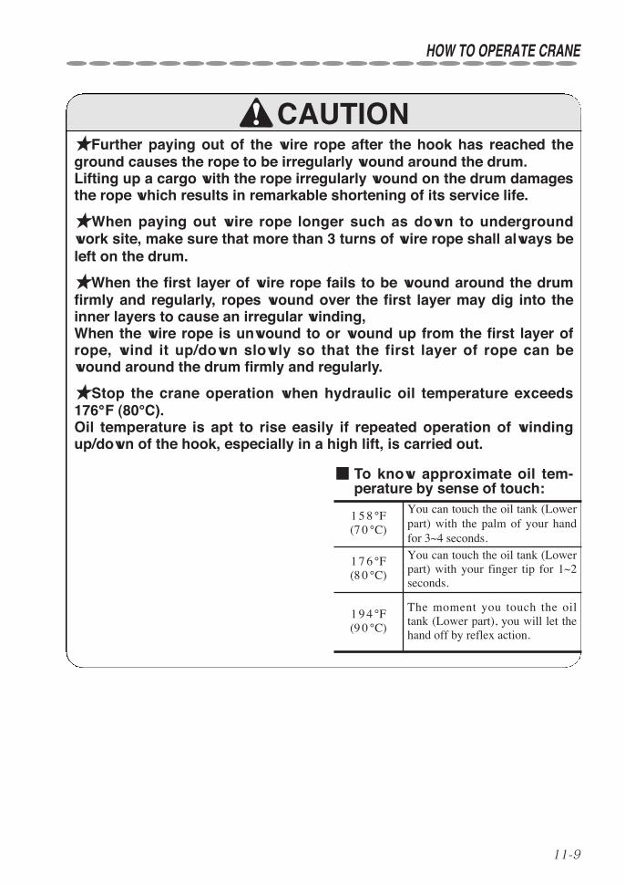
11-9
HOW TO OPERATE CRANE
★Further paying out of the wire rope after the hook has reached theground causes the rope to be irregularly wound around the drum.Lifting up a cargo with the rope irregularly wound on the drum damagesthe rope which results in remarkable shortening of its service life.
★When paying out wire rope longer such as down to undergroundwork site, make sure that more than 3 turns of wire rope shall always beleft on the drum.
★When the first layer of wire rope fails to be wound around the drumfirmly and regularly, ropes wound over the first layer may dig into theinner layers to cause an irregular winding,When the wire rope is unwound to or wound up from the first layer ofrope, wind it up/down slowly so that the first layer of rope can bewound around the drum firmly and regularly.
★Stop the crane operation when hydraulic oil temperature exceeds176°°F (80°C).Oil temperature is apt to rise easily if repeated operation of windingup/down of the hook, especially in a high lift, is carried out.
CAUTION
■ To know approximate oil tem-perature by sense of touch:
1 7 6 °F(8 0 °C)
You can touch the oil tank (Lowerpart) with your finger tip for 1~2seconds.
1 5 8 °F(7 0 °C)
1 9 4 °F(9 0 °C)
You can touch the oil tank (Lowerpart) with the palm of your handfor 3~4 seconds.
The moment you touch the oiltank (Lower part), you will let thehand off by reflex action.

11-10
yHow to telescope boom
★The hook is lifted up as the boom extends and is lowered as itretracts.When telescoping the boom, pay attention to where the hook is.
★If the boom is extended further with the hook come close to the boomtop, the hook may hit against the boom top causing the wire rope andthe sheaves at the boom top to be damaged, and the fall of lifted cargomay result.
★Be sure to turn ON the “alarm sound ON/OFF switch”.
To extendShift the lever to “EXTend” to extend theboom.To retractShift the lever to “RETract” to retract theboom.To stopReturn the lever to neutral position to stopthe boom telescoping.
◆Power automatic acceleratorWhen the control lever is shifted further to"EXT" or "RET", the engine speed increasesaccording to the movement of the leverwhich in turn increases telescoping speed ofthe boom as the lever is interlocked with theaccelerator.
WARNING
CAUTION
HOW TO OPERATE CRANE
Boom telescoping leverBoom To retract
Boom To extend
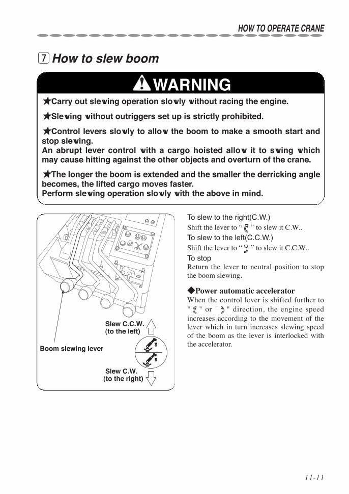
11-11
HOW TO OPERATE CRANE
uHow to slew boom
★Carry out slewing operation slowly without racing the engine.
★Slewing without outriggers set up is strictly prohibited.
★Control levers slowly to allow the boom to make a smooth start andstop slewing.An abrupt lever control with a cargo hoisted allow it to swing whichmay cause hitting against the other objects and overturn of the crane.
★The longer the boom is extended and the smaller the derricking anglebecomes, the lifted cargo moves faster.Perform slewing operation slowly with the above in mind.
To slew to the right(C.W.)Shift the lever to “ ” to slew it C.W..To slew to the left(C.C.W.)Shift the lever to “ ” to slew it C.C.W..
To stopReturn the lever to neutral position to stopthe boom slewing.
◆Power automatic acceleratorWhen the control lever is shifted further to" " or " " direction, the engine speedincreases according to the movement of thelever which in turn increases slewing speedof the boom as the lever is interlocked withthe accelerator.
WARNING
Boom slewing lever
Slew C.C.W.(to the left)
Slew C.W.(to the right)

11-12
For slewing direction of boom, “slew to theright” means slewing in the direction as thehands of a clock rotate (C.W.) and “slew tothe left” means slewing in the opposite direc-tion of clock hands rotate (C.C.W.) whenviewed over the crane.
★Before starting the boom to slew, sound the warning horn to thosewho are attending or in the working site.
HOW TO OPERATE CRANE
CAUTION
Slew C.C.W.(to the left )
Slew C.W.(to the right)

11-13
HOIST. With forearm verti-cal, forefinger pointing up,move hand in small horizon-tal circle.
LOWER. With arm extendeddownward, forefinger point-ing down, move hand insmall horizontal circle.
USE MAIN HOIST. Tap fiston head; then use regularsignals.
USE WHIPLINE(Auxil iaryHoist). Tap elbow with onehand; then use regular sig-nals.
RAISE BOOM. Arm extend-ed, fingers closed, thumbpointing upward.
LOWER BOOM. Arm extend-ed, fingers closed, thumbpointing downward.
MOVE SLOWLY. Use onehand to give any motion sig-nal and place other handmotionless in front of handgiving the motion signal.(Hoistslowly shown as example.)
RAISE THE BOOM ANDLOWER THE LOAD. Witharm extended, thumb point-ing up, flex fingers in and outas long as load movement isdesired.
LOWER THE BOOM ANDRAISE THE LOAD. With armextended, thumb pointingdown, flex fingers in and outas long as load movement isdesired.
HOW TO OPERATE CRANE

11-14
SWING. Arm extended, pointwith finger in direction ofswing of boom.
STOP. Arm extended, palmdown, move arm back andforth horizontally.
EMERGENCY STOP. Botharms extended, palms down,move arms back and forthhorizontally.
TRAVEL. Arm extended for-ward, hand open and slightlyraised, make pushing motionin direction of travel.
DOG EVERYTHING. Clasphands in front of body.
TRAVEL.(One Track)Lock thetrack on side indicated byraised fist.Travel opposite track in direc-tion indicated by circularmotion of other fist, rotated ver-tically in front of body. (For landcranes only.)
EXTEND BOOM (TelescopingBooms).Both fists in front ofbody with thumbs pointingoutward.
RETRACT BOOM (TelescopingBooms).Both fists in front ofbody with thumbs pointingtoward each other.
EXTEND BOOM (TelescopingBoom). One Hand Signal.One fist in front of chest withthumb tapping chest.
RETRACT BOOM (TelescopingBoom). One Hand Signal. Onefist in front of chest, thumb point-ing out-ward and heel of fist tap-ping chest.
TRAVEL(Both Tracks). Useboth fists in front of body,making a circular motionabout each other, indicatingdirection of travel, forward orbackward. (For land cranesonly.)
HOW TO OPERATE CRANE
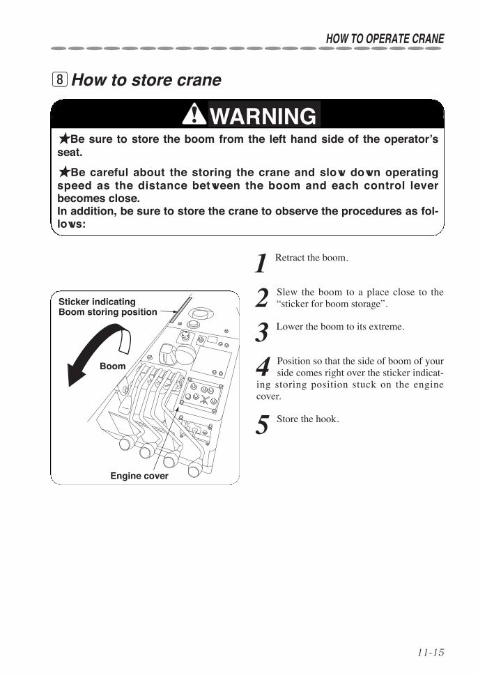
11-15
HOW TO OPERATE CRANE
iHow to store crane
★Be sure to store the boom from the left hand side of the operator’sseat.
★Be careful about the storing the crane and slow down operatingspeed as the distance between the boom and each control leverbecomes close.In addition, be sure to store the crane to observe the procedures as fol-lows:
1 Retract the boom.
2 Slew the boom to a place close to the“sticker for boom storage”.
3 Lower the boom to its extreme.
4 Position so that the side of boom of yourside comes right over the sticker indicat-
ing storing position stuck on the enginecover.
5 Store the hook.
WARNING
Engine cover
Sticker indicating Boom storing position
Boom

11-16
1 Hoist up the hook with the “hook storingswitch” turned to “Store”.
The hook stops being wound up when thehook hits against the weight of over-windingalarm.
2 Wind up the hook slowly by controllingthe hook storing switch after the hook is
at a standstill.Release the switch after the hook has beenstored.
oProcedures for storing hook
★Never try operating the crane by controlling the hook storing controlswitch as this is dangerous.
★Store the hook after all boom sections have been retracted and low-ered fully.
★Do not operate the hook storing control switch and other controllever at the same time which may cause an malfunction and a break-down.
HOW TO OPERATE CRANE
WARNING
Hook storing switch
To store
★Storing hook while it is swing-ing may cause the boom, thehook, and the wire rope to bedamaged.
★Take care that the manual con-trol lever for hoisting/loweringhook moves toward hoisting sidewhen storing the hook.
CAUTION
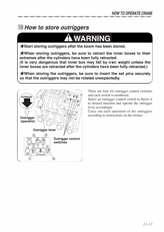
11-17
!0How to store outriggers
★Start storing outriggers after the boom has been stored.
★When storing outriggers, be sure to retract the inner boxes to theirextremes after the cylinders have been fully retracted.(It is very dangerous that inner box may fall by own weight unless theinner boxes are retracted after the cylinders have been fully retracted.)
★When storing the outriggers, be sure to insert the set pins securelyso that the outriggers may not be rotated unexpectedly.
HOW TO OPERATE CRANE
WARNING
There are four (4) outrigger control switchesand each switch is numbered.Select an outrigger control switch to throw itto desired function and operate the outriggerlever accordingly.Carry out each operation of the outriggersaccording to instructions on the sticker.
①
② ③
④
①
② ③
④
OUTRIGGER
Outrigger operation
Outrigger lever
Outrigger control switches
EXT
RETOUTRIGGER
CRANE
HORN
MODE
OUTRIGGERS
EXT
RET
EXT
RET
EXT
RET

11-18
Store the outriggers as follows:
1 Retract the cylinders fully first to retractthe inner boxes to their extremes.
2 Remove the lock pin (2), push in theinner box fully, and insert the lock pin
(2) back again.Retain the lock pin with a stopper pin.
3 Remove the lock pin (1) in the arm andhold the knob of outer box firmly to
push it down strongly.Insert the lock pin (1) and retain it with astopper pin..
4 Remove the outrigger set pin and insertit securely in appropriate place so that
the outrigger may not be rotated unexpected-ly.
●RemarksOutriggers may be lowered while crawlingfor a long time which is not a fault.
Arm
Lock pin (1)
Knob
Inner box
Outer box
Lock pin (2)
HOW TO OPERATE CRANE

11-19
HOW TO OPERATE CRANE
!1How to switch manual operation mode to/fromradio remote control mode
1 Put the traveling lever stand in the oper-ating position of the crane.
2 Check that each lever for controlling thecrane and the outriggers stays at its neu-
tral position.
3 Start the engine.
4 When operated in manual control mode,the outriggers and the crane can only be
operated by manual control.No operation can be carried out through radioremote controller. The operation mode indicator lamp locatedon the top of cover will not be lit during man-ual control mode.
5 Push the mode selector switch to switchit to the radio remote control mode.
6 When it is switched to the radio remotecontrol mode, the outriggers and the
crane can only be operated through radioremote controller.Turn ON the radio remote controller to carryout remote control operation.The outriggers and the crane cannot be oper-ated by manual control.
7 When switched to radio remote controlmode, the operation mode indicator
lamp located on the top of cover will be lit.
The lamp should always be lit when operatedon radio control mode.
Mode indicator lamp
Mode selector switch

11-20
★The state of each operation mode will be maintained even after thepower has once been turned OFF.Check the operation mode and the operation mode indicator lamp whenit has been re-started.
★The operation mode indicator lamp functions according to each oper-ation mode as follows:
Radio control mode : Operation mode indicator lamp lights.Manual operation mode : Operation mode indicator lamp goes off.
CAUTION
HOW TO OPERATE CRANE

11-21
Outrigg
HOW TO OPERATE CRANE
!2How to operate outriggers when in an emergency
★Do not touch the engine, muffler and its cover with your barefinger/hand as they are very hot immediately after operation.
★Be sure to put the cover back again after the outriggers have beenstored.
WARNING
If outriggers fail to make a functioning cor-rectly in normal operation, operate outriggerstemporarily according to procedures illustrat-ed below.
1 Remove the cover over the outriggervalves.
Remove the thumb-screws (6 places) toremove the cover.
2 Push the solenoid valve button of outrig-ger you want to operate with a bar such
as screwdriver.When the outrigger control lever concernedoperates, the outrigger functions.
Remove this cover
1
4
3
2
12
3
5
7
4
6
8RETEXT
EXT
EXT
EXT
RET
RET
RET
★While cover is being removed or when depressing a solenoid valvebutton, work carefully not to damage the electric wiring.
★After the procedures have been completed, have the crane repairedby the nearest UNIC service shop.
CAUTION
Outrigger to be operated Operation
Outrigger ①Retract Operate lever with button 1 depressed
Extend Operate lever with button 2 depressed
Outrigger ②Retract Operate lever with button 5 depressed
Extend Operate lever with button 6 depressed
Outrigger ③Retract Operate lever with button 7 depressed
Extend Operate lever with button 8 depressed
Outrigger ④Retract Operate lever with button 3 depressed
Extend Operate lever with button 4 depressed

12-1
12. U-WAVE, Radio remote control device
qRequest to those who operate the craneThis radio remote control device conforms to regulations for specified small power radio stationin the radio wave law.Use of U-WAVE, “specific low power type” interlocking radio control device, allows the craneoperation that will hardly be influenced by radio interference compared with conventional radioremote controllers of weak radio wave type.In addition, there is no need to get qualification, license, or registration in using the radioremote control device.Read this manual carefully and understand the contents to use this device.
♦When making inquiries When making inquiries, be sure to inform us of model, serial number illustrated on the follow-ing label in the remote control transmitter.
AUS-HA10001Serial number
5-digit (consecutive number)
Alphabets (frequecncy classification)
Type clasification
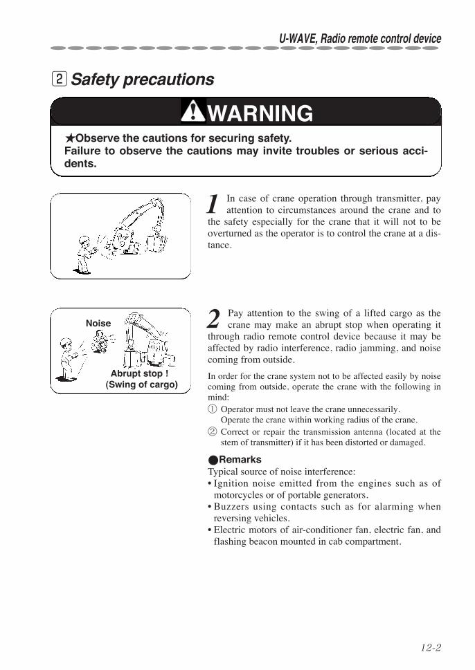
12-2
U-WAVE, Radio remote control device
wSafety precautions
2 Pay attention to the swing of a lifted cargo as thecrane may make an abrupt stop when operating it
through radio remote control device because it may beaffected by radio interference, radio jamming, and noisecoming from outside.
In order for the crane system not to be affected easily by noisecoming from outside, operate the crane with the following inmind:① Operator must not leave the crane unnecessarily.
Operate the crane within working radius of the crane.② Correct or repair the transmission antenna (located at the
stem of transmitter) if it has been distorted or damaged.
●RemarksTypical source of noise interference:• Ignition noise emitted from the engines such as of
motorcycles or of portable generators.• Buzzers using contacts such as for alarming when
reversing vehicles.• Electric motors of air-conditioner fan, electric fan, and
flashing beacon mounted in cab compartment.
★Observe the cautions for securing safety.Failure to observe the cautions may invite troubles or serious acci-dents.
WARNING
1 In case of crane operation through transmitter, payattention to circumstances around the crane and to
the safety especially for the crane that it will not to beoverturned as the operator is to control the crane at a dis-tance.
Abrupt stop ! (Swing of cargo)
Noise
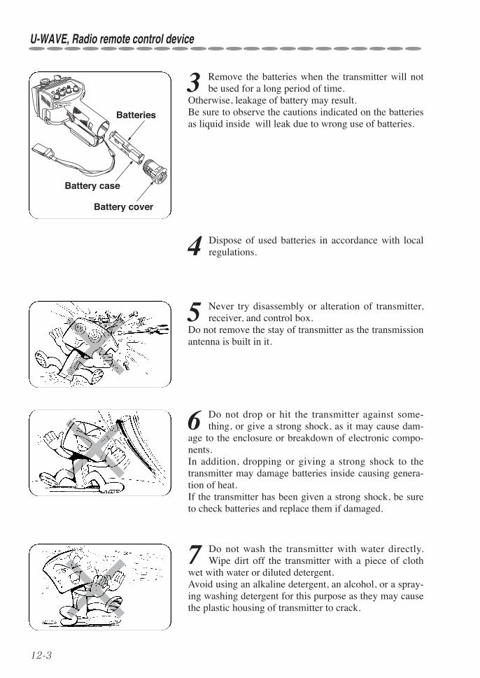
12-3
7 Do not wash the transmitter with water directly.Wipe dirt off the transmitter with a piece of cloth
wet with water or diluted detergent.Avoid using an alkaline detergent, an alcohol, or a spray-ing washing detergent for this purpose as they may causethe plastic housing of transmitter to crack.
5 Never try disassembly or alteration of transmitter,receiver, and control box.
Do not remove the stay of transmitter as the transmissionantenna is built in it.
6 Do not drop or hit the transmitter against some-thing, or give a strong shock, as it may cause dam-
age to the enclosure or breakdown of electronic compo-nents.In addition, dropping or giving a strong shock to thetransmitter may damage batteries inside causing genera-tion of heat.If the transmitter has been given a strong shock, be sureto check batteries and replace them if damaged.
3 Remove the batteries when the transmitter will notbe used for a long period of time.
Otherwise, leakage of battery may result.Be sure to observe the cautions indicated on the batteriesas liquid inside will leak due to wrong use of batteries.
4 Dispose of used batteries in accordance with localregulations.
Battery cover
Batteries
Battery case
U-WAVE, Radio remote control device

12-4
U-WAVE, Radio remote control device
8 Do not thrust the control panel in the transmitterand/or control keys with a sharp article as it may
make a hole resulting in entering water inside through it.
9 Do not give the transmitter an abrupt temperaturechange.
An abrupt temperature change may cause a fault due tobuilding-up condensation inside of the transmitter.
10 Do not put or store the transmitter where:
• It is exposed to direct sunlight,• It is in front of hot air outlet exhausted out of the vehi-
cle, and• It is close to a heating apparatus or it is too humid.

12-5
eDesignation of each equipment◆1. Construction of radio remote control device
(Showing typical mounting example)
Control boxReceiver
Transmitter
Hooking band
Carrying hook
U-WAVE, Radio remote control device

12-6
U-WAVE, Radio remote control device
◆2. Designation of each part of transmitter
Mode switch
Power lamp
E-stop switch
Key switch
Speed selector switch
Horn (Start) switch
Speed lever
Boom Extending/Retracting (P ON/OFF)(Extension/Retraction of outrigger ②) Selector
switches
Storing hook
Boom raising/lowering(Extension/Retraction of outrigger ④)
Slewing C.C.W./C.W.Engine Start/Stop(Extension/Retraction of outrigger ①)
Hook Hoisting/Lowering(Extension/Retraction of outrigger ③)
◆3. Designation of each part of receiver
Checking lamp *Receiving antenna is built in the receiver.

12-7
◆4. Designation of each part of control box
09R886211-W295CR
Control box reset switch
Mode indicator lamp
CONTROL BOXRESET SWITCH
RESET
U-WAVE, Radio remote control device
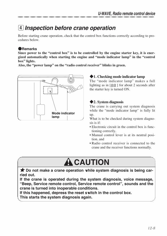
12-8
U-WAVE, Radio remote control device
Before starting crane operation, check that the control box functions correctly according to pro-cedures below.
●RemarksSince power to the “control box” is to be controlled by the engine starter key, it is ener-gized automatically when starting the engine and “mode indicator lamp” in the “controlbox” lights.Also, the “power lamp” on the “radio control receiver” blinks in green.
◆1. Checking mode indicator lampThe “mode indicator lamp” makes a fulllighting as in [ ] for about 2 seconds afterthe starter key is turned ON.
◆2. System diagnosisThe crane is carrying out system diagnosiswhile the “mode indicator lamp” is fully litup.What is to be checked during system diagno-sis is if: • Electronic circuit in the control box is func-
tioning correctly,• Manual control lever is at its neutral posi-
tion, and• Radio control receiver is connected to the
crane and the receiver functions normally.
r Inspection before crane operation
Mode indicator lamp
★ Do not make a crane operation while system diagnosis is being car-ried out.If the crane is operated during the system diagnosis, voice message,“Beep, Service remote control, Service remote control”, sounds and thecrane is turned into inoperable conditions. If this happened, depress the reset switch in the control box.This starts the system diagnosis again.
CAUTION

12-9
If it was found normal after the system diagnosis has been completed, the mode indicator lamplights either one of following indication and voice message, “Ping-pong, Remote controlready, Remote control ready”, is issued.
• Since priority is assigned for each mode in its information, it is to be indicated in the order ofhigher priority.
●RemarksIf the “mode indicator lamp” indicates [ ], current control is on outrigger radio con-trol mode.No crane operation other than extension/retraction of outriggers is possible.When operating the crane, turn the “crane/outrigger operation mode selector” switch to“crane”.
★ If the “mode indicator lamp” fails to make a full lighting during sys-tem diagnosis, or voice message, “Beep, Service remote control,Service remote control”, is issued despite the fact that the crane hasnot been operated, take measures according to the section 12. i ◆3.“Trouble inspection” (on page 12-39).
CAUTION
Mode Information Indication priority
Current operation mode is on normal radio remote controlmode.
4
Current operation mode is traveling mode. 1
Current operation mode is on outrigger radio remote controlmode.
2
Hook hits against weight for over-winding alarm (over-woundcondition).
3
U-WAVE, Radio remote control device
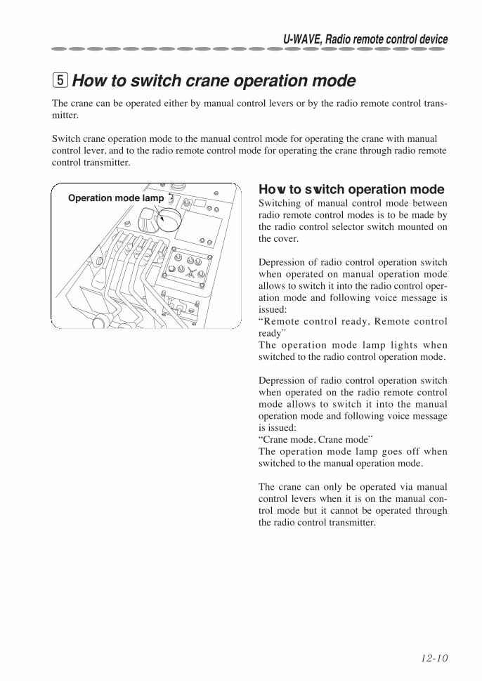
12-10
U-WAVE, Radio remote control device
tHow to switch crane operation modeThe crane can be operated either by manual control levers or by the radio remote control trans-mitter.
Switch crane operation mode to the manual control mode for operating the crane with manualcontrol lever, and to the radio remote control mode for operating the crane through radio remotecontrol transmitter.
Operation mode lampHow to switch operation modeSwitching of manual control mode betweenradio remote control modes is to be made bythe radio control selector switch mounted onthe cover.
Depression of radio control operation switchwhen operated on manual operation modeallows to switch it into the radio control oper-ation mode and following voice message isissued: “Remote control ready, Remote controlready”The operation mode lamp lights whenswitched to the radio control operation mode.
Depression of radio control operation switchwhen operated on the radio remote controlmode allows to switch it into the manualoperation mode and following voice messageis issued: “Crane mode, Crane mode”The operation mode lamp goes off whenswitched to the manual operation mode.
The crane can only be operated via manualcontrol levers when it is on the manual con-trol mode but it cannot be operated throughthe radio control transmitter.

12-11
The crane can only be operated through the radio control transmitter when it is on the radioremote control mode but it cannot be operated via manual control levers (including outriggers).
List of available functions to be operated on each control mode
Operation ○: Possible ×: Impossible
●RemarksThe crane cannot be operated both by manual and by radio remote control without selectingoperation mode.
The operation mode is to be memorized even after power to the crane has been turned OFF.
Crane operationOperation mode
Manual Radio remote control
Manual lever Boom Raising/Lowering ○ ×Hook Hoisting/Lowering ○ ×Boom Extending/Retracting ○ ×Slewing C.C.W./C.W. ○ ×Outrigger Extend/Retract ○ ×
Radio remotecontrol trans-mitter
Boom Raising/Lowering × ○Hook Hoisting/Lowering × ○Boom Extending/Retracting × ○Slewing C.C.W./C.W. × ○Storing hook × ○Mode × ○Speed select × ○Horn × ○Emergency stop × ○Engine Start/Stop ─ ○
U-WAVE, Radio remote control device

12-12
U-WAVE, Radio remote control device
yHow to operate the crane through radio controloperation
◆1. Preparation before operation1. Extend the outriggers to their maximumwith the manual control lever and level thecrane.
• The outriggers are to be controlled on man-ual operation mode.If manual mode has not been selected,depress the “radio remote control selectorswitch” on the switch panel to turn it to beoperated on manual mode.
●RemarksIf a crane operation (such as boomUp/Down, hook Up/Down, boomExtend/Retract, and swing C.C.W./C.W.) iscarried out while the outriggers are beingextended or retracted by manual controllever, the crane will make an automaticstop to avoid dangerous situation.(The “mode indicator lamp” blinks [ ].Refer to section “18. Mode indicatorlamp” on page 18-1 for detail.)If this has taken place, stop both operationof the crane and of the outriggers once andtry carrying out extension and retractionof outriggers again.
2. Check that the “E-stop switch” on thetransmitter has been reset to turn ON the“key switch”. If the “E-stop switch” has not been reset, turnthe switch clockwise to reset it.• Emergency stop function is to be actuated if
the “E-stop switch” is pushed in, and emer-gency stop resets when it is not beingdepressed.
Power lamp
E-stop switchKey switch Horn (Start) switch

12-13
3. Depression of the “horn (start) switch” onthe transmitter energizes the transmitter and“power lamp” lights (in red, in orange, or ingreen).
• Power to the transmitter is to be turned OFFby pushing in the “E-stop switch”, or byturning OFF the “key switch”, or if time haspassed for more than 5 minutes when nocrane operation has been carried out.
• If the “power lamp” blinks or fails to be lit,replace batteries of transmitter according tothe section 12. u “◆3.How to replace bat-teries” illustrated on page 12-36.
4. Check that the voice switch has beenturned ON.If not, turn it ON.
●RemarksVoice message will not be issued when thevoice switch has been turned OFF.
5. Depress the “radio remote control selectorswitch” on the switch panel to turn it to beoperated on radio remote control mode. The mode indicator lamp indicates [ ] andthe following voice message is issued:“Remote control ready, Remote controlready”
• When the operation mode is switched to“radio remote control mode.” with power totransmitter turned OFF, the mode indicatorlamp indicates [ ].Turning ON the power to the transmitterallows the mode indicator lamp to indicate[ ].
ON
OFF
Over-winding alarm switch
U-WAVE, Radio remote control device
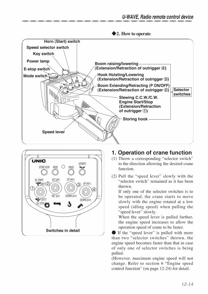
12-14
U-WAVE, Radio remote control device
◆2. How to operate
412 3
Switches in detail
STORE HOOK
(RET)
(START)
(EXT)(En. STOP)
MODE
EXT (RET)
RET (EXT)
SPEED
UP (RET)
DOWN (EXT)
UP (RET)
DOWN (EXT)
(En. START)
1. Operation of crane function(1) Throw a corresponding “selector switch”
to the direction allowing the desired cranefunction.
(2) Pull the “speed lever” slowly with the“selector switch” remained as it has beenthrown.If only one of the selector switches is tobe operated, the crane starts to moveslowly with the engine rotated at a lowspeed (idling speed) when pulling the“speed lever” slowly.When the speed lever is pulled further,the engine speed increases to allow theoperation speed of crane to be faster.
● If the “speed lever” is pulled with morethan two “selector switches” thrown, theengine speed becomes faster than that in caseof only one of selector switches is beingpulled.(However, maximum engine speed will notchange. Refer to section 6 “Engine speedcontrol function” (on page 12-24) for detail.
Mode switch
Power lamp
E-stop switch
Key switch
Speed selector switch
Horn (Start) switch
Speed lever
Boom Extending/Retracting (P ON/OFF)(Extension/Retraction of outrigger ②) Selector
switches
Storing hook
Boom raising/lowering(Extension/Retraction of outrigger ④)
Slewing C.C.W./C.W.Engine Start/Stop(Extension/Retraction of outrigger ①)
Hook Hoisting/Lowering(Extension/Retraction of outrigger ③)

12-15
★ When operating the crane with the radio remote control transmitter,be sure not to touch any of manual levers as manual levers shift simul-taneously.
WARNING
(3) When stopping the crane operation,return the “speed lever” slowly, and thenreturn the “selector switch”.
(4) Depression of the “horn switch” activatesthe horn on the vehicle.Use it when calling attention to thosewho stand around the vehicle.
●Remarks• Switches mounted on the remote con-
troller are ON/OFF type which can beactuated with a light touch.Do not apply strong force as it may causedamage to the switches.
• When the same radio wave (of specifiedsmall power radiation type radio system)is being used near he working site,response time of the crane it takes fromthe time when the radio remote controldevise has been operated may becomelonger to some extent which is not afault.
• When operating with the remote con-troller, working speed may become a bitslower than that of manual operation.
Horn switch
U-WAVE, Radio remote control device

12-16
U-WAVE, Radio remote control device
2. How to confirm and changespeed mode
When operating the crane with the enginerunning at a medium speed, or at a lowerspeed such as in case of working at night, thespeed mode can be changed.
(1) How to confirm speed modeCheck the “power lamp” for lighting color, ifit is lit in;① Red : High speed mode② Orange : Medium speed mode③ Green : Low speed mode
If the “power lamp” is not lit, turn ON thepower to transmitter to light the “powerlamp”.
● Orange illumination is realized by lightingboth red and green LED elements. Red and green LEDs may be seen separatelywhere it is in a lot of sunshine.
(2) How to change speed modeConfirm that the “power lamp” is lit todepress the “speed selector switch”.Every time the “speed selector switch” isdepressed, the “power lamp” lights in theorder of
Power lamp (Lighting in red)
(High speed mode)Speed selector switch
Power lamp (Lighting in orange)
(Medium speed mode)Speed selector switch
Power lamp (Lighting in green)
(Low speed mode)Speed selector switch
Red Orange Green
changing speed mode accordingly.
Depression of the “speed selector switch withthe “power lamp” lit in red allows the lamp tolight in orange changing it into on mediumspeed mode.
Depression of the “speed selector switch”with the “power lamp” lit in orange allowsthe lamp to light in green changing it into onlow speed mode.
Depression of the “speed selector switch”with the “power lamp” lit in green allows thelamp to light in red changing it into on highspeed mode.

12-17
●RemarksSetting of speed mode is to be memorized even when power to transmitter has beenturned OFF.Note that a slight speed difference between slewing C.C.W./C.W. may be found when slew-ing it on the low speed mode which is not a fault.
(3) Speed mode and manual lever controlManual lever control is also applied to the speed mode.
High speed mode.................Engine will run at maximum speed.Medium speed mode ...........Engine will run at medium speed range.Low speed mode..................Engine will run at close to idling speed.
●RemarksSpeed mode can only be changed through radio control transmitter.Speed mode switches to high speed mode when power to the crane is turned OFF (starterswitch is turned OFF).
Since setting of speed mode is memorized even when power to radio control transmitter hasbeen turned OFF, speed mode is switched to the mode as the radio control transmitter has mem-orized previously when the crane is operated through radio control transmitter after power tothe crane is turned ON again.
U-WAVE, Radio remote control device

12-18
U-WAVE, Radio remote control device
3. Interlocking balance control functionWhen interlocking operation (operation of speed lever with more than 2 of “selector switches”thrown) is carried out through the radio control transmitter, the system equips the function con-trolling movement of each control lever for each combination of the “selector switches”.
Therefore, when the speed lever is pulled to its extreme, movement of each control lever variesin accordance with combination of “selector switches”.
In some cases, the control lever may not be shifted to its full extent despite the fact that thespeed lever on the radio control transmitter has been fully pulled which is not a fault.
●Remarks On interlocking balance retaining function:The crane equips interlocking retaining function which prevent its operating speed from makingan abrupt increase when interlocking operation is switched to independent operation,
When operation is switched from interlocking to independent (change from operation of speedlever with more than 2 of “selector switches” thrown to operation of speed lever with one of“selector switches” thrown), control speed may become slower as oppose to that of the indepen-dent operation, which is not a fault.In order to correct this, release all the “selector switches” once and go back to independentoperation again.
For immediate returning to normal speed of independent operation when it is switched frominterlocking to independent, validity of interlocking balance retaining function can be switchedthrough the transmitter.
In order for the interlocking balance retainingfunction to be invalid, depress the “storehook” switch with the “boom Up/Down”switch turned to ”Down”.Voice message, “Change control mode,Change control mode”, sounds and the inter-locking balance retaining function changes tobe invalid.(The voice message does not sound when thefunction remains as it was.)Switching condition of the interlocking bal-ance retaining function can be confirmed asthe mode indicator is to be lit as in [ ](meaning “invalid”) while the switch is beingcontrolled.
Boom Up/Down switch
Store Hook switch
Speed lever

12-19
4. Temporary changing function of interlocking balance (Clickoperation)
When interlocking operation with 2 “selector switches” thrown (2-interlocking operation) iscarried out with the radio control transmitter, each speed balance can be changed temporarily.
Click a “selector switch” for which faster speed is needed during 2-interlocking operation.Operating speed related to the “clicked” switch becomes faster than that of other operation.The more number of times a switch has been clicked, the faster the operation related to theclicked switch becomes as opposed to against that of other operation relatively.
Turning OFF both “selector switches” on 2-interlocking operation releases the function to allowthem to return to previous conditions.
In order for the interlocking balance retaining function to be valid, depress the “store hook”switch with the “boom Up/Down” switch turned to ”Up”.Voice message, “Change control mode, Change control mode”, sounds and the interlocking bal-ance retaining function changes to be valid.(The voice message does not sound when the function remains as it was.)Switching condition of the interlocking balance retaining function can be confirmed as themode indicator is to be lit as in [ ] (meaning “valid)” while the switch is being controlled.
★Be careful that the operation speed returns to that of independentoperation immediately when it is switched from interlocking to indepen-dent with the interlocking balance retaining function switched to beinvalid.
CAUTION
●RemarksIf the “boom Up/Down” switch is controlled before depression of the “store hook” switch,voice message, “Ping-pong, Secure lifting hook, Secure lifting hook”, may sounds which is nota fault.The interlocking balance retaining function switches regardless of sounding voice massage.
The interlocking balance retaining function is to be memorized even after power to the cranehas been turned OFF.
U-WAVE, Radio remote control device

12-20
U-WAVE, Radio remote control device
(Switch in detail)
E-STOP OFF ON
STORE HOOK
(RET)
(START)
(EXT)(En. STOP)
MODE
EXT (RET)
RET (EXT)
SPEED
UP (RET)
DOWN (EXT)
UP (RET)
DOWN (EXT)
(En. START)
Speed increases
(Switch in detail)
E-STOP OFF ON
STORE HOOK
(RET)
(START)
(EXT)(En. STOP)
MODE
EXT (RET)
RET (EXT)
SPEED
UP (RET)
DOWN (EXT)
UP (RET)
DOWN (EXT)
(En. START)
● Example of operationInterlocking operation of both “Boom extending” and “Hook Lowering”.
Pull the speed lever with the “hookUp/Down” switch thrown to “Down” and the“Boom Ext/Ret” switch put to “Ext”.
The hook lowers and the boom starts toextend.
●To increase extending speed of boomClick (operate it quickly in order of ON→OFF→ON) the “Boom Ext/Ret” switch to“Ext” side.This allows extending speed of boom tobecome faster than that of hook down.
The more number of times the switch hasbeen clicked toward “Ext”, the faster theboom extension becomes as oppose to that ofhook down.
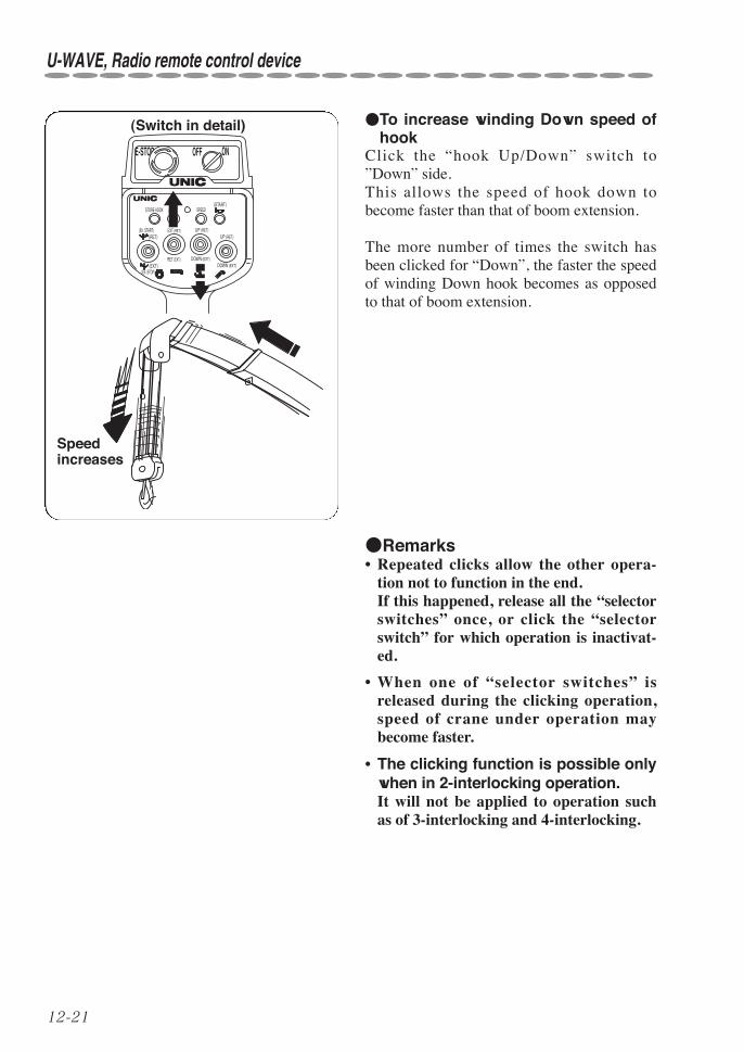
12-21
Speed increases
(Switch in detail)
E-STOP OFF ON
STORE HOOK
(RET)
(START)
(EXT)(En. STOP)
MODE
EXT (RET)
RET (EXT)
SPEED
UP (RET)
DOWN (EXT)
UP (RET)
DOWN (EXT)
(En. START)
●To increase winding Down speed ofhook
Click the “hook Up/Down” switch to”Down” side.This allows the speed of hook down tobecome faster than that of boom extension.
The more number of times the switch hasbeen clicked for “Down”, the faster the speedof winding Down hook becomes as opposedto that of boom extension.
●Remarks• Repeated clicks allow the other opera-
tion not to function in the end. If this happened, release all the “selectorswitches” once, or click the “selectorswitch” for which operation is inactivat-ed.
• When one of “selector switches” isreleased during the clicking operation,speed of crane under operation maybecome faster.
• The clicking function is possible onlywhen in 2-interlocking operation.It will not be applied to operation suchas of 3-interlocking and 4-interlocking.
U-WAVE, Radio remote control device

12-22
U-WAVE, Radio remote control device
5. Shock-less functionThe system equips a “shock-less” functionallowing the crane to stop gently even whenthe crane has been made an abrupt stop byradio control transmitter.
Since the crane will not make an abrupt stopagainst a sharp operation, it eases shock tothe crane and/or to the mounted vehicle, andit is also effective to prevent the wire ropefrom jumping up and a lifted cargo fromswinging when the hook has stopped wind-ing-up.
★ Pay attention that the cranemakes a slight movement due toshock-less function after theradio control operation has beenstopped abruptly.
CAUTION
●RemarksWhen making the crane a suddenstop:If the crane has to be made a sudden stop,actuate the “selector switch” controllingopposite function while the shock-less isfunctioning.(Do not pull the speed lever in this case.)Otherwise, the shock-less function isreleased to allow the crane to make a sud-den stop.
When canceling the shock-less func-tion:If the shock-less function is unnecessary, itcan be activated/inactivated by the radiocontrol transmitter.

12-23
Mode switchHook Up/Down switch
In order to inactivate the shock-less function,throw the “hook Up/Down” switch to“Down” with the “mode switch” depressed.The shock-less will not be functioning.
In order to activate the shock-less function,throw the “hook Up/Down” switch to “Up”with the “mode switch” depressed.The shock-less starts functioning.
When the shock-less function is active and the “mode indicator lamp” shows any of [ ], [ ],[ ], [ ] and [ ], switching it to be inactive allows the figure indicated on the left to change to[ ].Switching the shock-less function to be active allows the mark [ ] indicated on the left to change to[ ].
★ Be sure to check if the modeindicator changes accordinglyafter the shock-less function hasbeen switched.
CAUTION
●RemarksWhen the mode indicator shows [ ](over-wound condition), no change hap-pens even after the shock-less function hasbeen switched.When checking condition of the shock-lessfunction, remove the over-wound conditionby operation of lowering hook or retract-ing boom.Setting of shock-less function is to be mem-orized after power to the crane has beenturned OFF.
Mode display
When shock-less function active: When shock-less function inactive:
Mode indicator lamp
U-WAVE, Radio remote control device
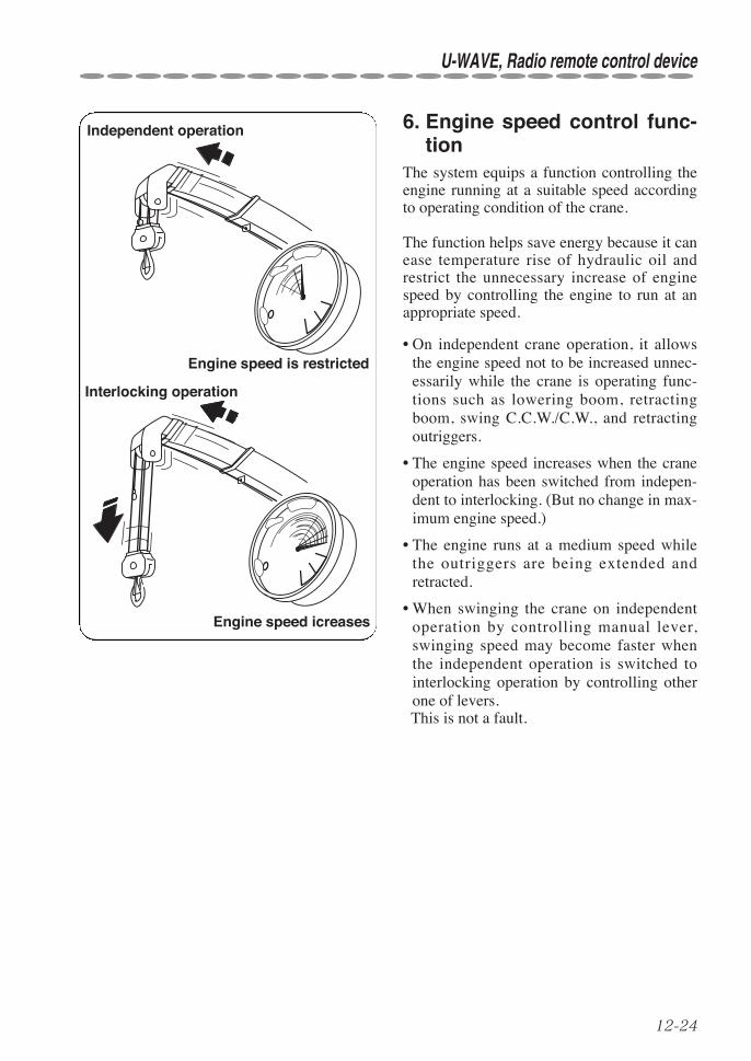
12-24
U-WAVE, Radio remote control device
Engine speed icreases
Independent operation
Engine speed is restricted
Interlocking operation
6. Engine speed control func-tion
The system equips a function controlling theengine running at a suitable speed accordingto operating condition of the crane.
The function helps save energy because it canease temperature rise of hydraulic oil andrestrict the unnecessary increase of enginespeed by controlling the engine to run at anappropriate speed.
• On independent crane operation, it allowsthe engine speed not to be increased unnec-essarily while the crane is operating func-tions such as lowering boom, retractingboom, swing C.C.W./C.W., and retractingoutriggers.
• The engine speed increases when the craneoperation has been switched from indepen-dent to interlocking. (But no change in max-imum engine speed.)
• The engine runs at a medium speed whilethe outriggers are being extended andretracted.
• When swinging the crane on independentoperation by controlling manual lever,swinging speed may become faster whenthe independent operation is switched tointerlocking operation by controlling otherone of levers.This is not a fault.
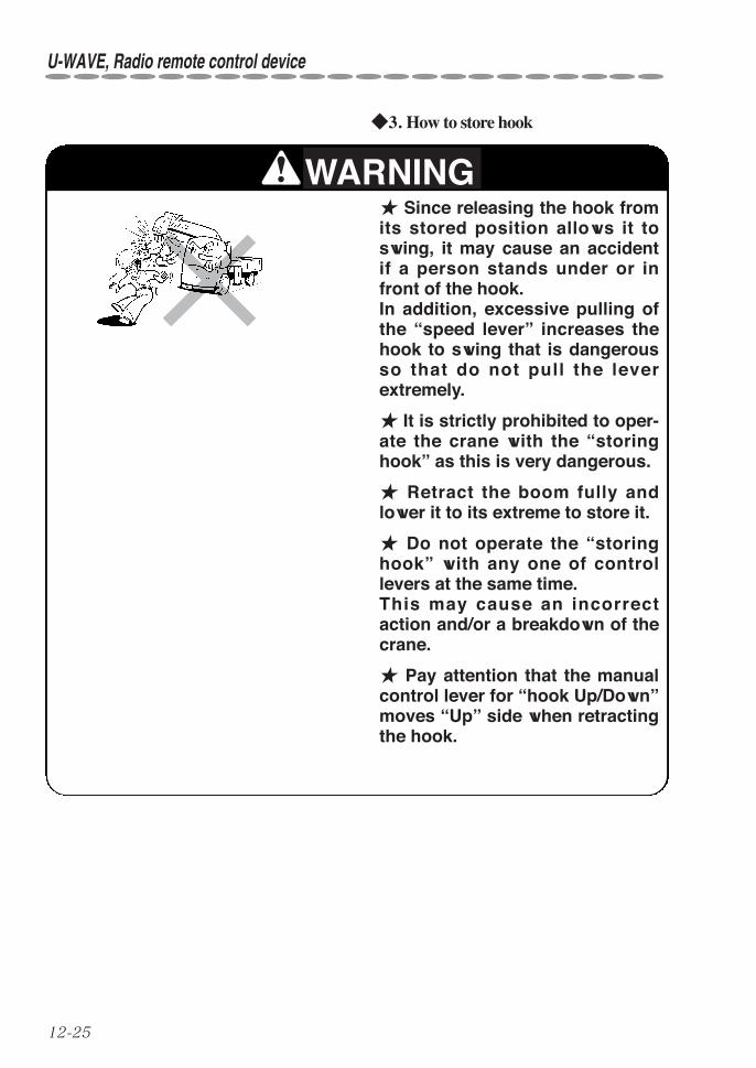
12-25
◆3. How to store hook
★ Since releasing the hook fromits stored position allows it toswing, it may cause an accidentif a person stands under or infront of the hook.In addition, excessive pulling ofthe “speed lever” increases thehook to swing that is dangerousso that do not pull the leverextremely.
★ It is strictly prohibited to oper-ate the crane with the “storinghook” as this is very dangerous.
★ Retract the boom fully andlower it to its extreme to store it.
★ Do not operate the “storinghook” with any one of controllevers at the same time.This may cause an incorrectaction and/or a breakdown of thecrane.
★ Pay attention that the manualcontrol lever for “hook Up/Down”moves “Up” side when retractingthe hook.
WARNING
U-WAVE, Radio remote control device

12-26
U-WAVE, Radio remote control device
(1) Wind up the hook with the “hookUp/Down” of selector switches.The hook stops being wound-up automati-cally when it hits against the weight forover-winding alarm.
●When it stops being wound-up, follow-ing voice message, “Beep, Stop winchup, Stop winch up, Beep, Beep• • • • • • ” is issued.The last part of voice message, “Beep,Beep • • • • • • ”, stops sounding whenthe operation concerned has beenstopped.
(2) Depress the “store hook” switch after thehook is at a standstill.
●Following voice message, “Ping-pong,Secure lifting hook, Secure liftinghook” is issued.
(3) When pulling the “speed lever” with the“store hook” switch depressed, the hookstarts being wound up slowly.
The “mode indicator lamp” indicates [ ]while the hook is being stored.
★Storing the hook while it isswinging may cause damage tothe boom, to the hook itself, andto the wire rope.
CAUTION
Hook Up/Down switch
Speed lever
Store Hook switch

12-27
(4) The hook hits against the guide on theboom top to be stored in positionStoring hook operation stops when the“speed lever” is returned and then the“store hook” switch is returned.
●RemarksThe engine is still running at a low speed(idling) while the hook is being stored.
★If the hook hits against theguide on the boom top obliquelyor it is off the guide halfway,wind-down the hook to try stor-ing operation again.
CAUTIONStoring hook
U-WAVE, Radio remote control device
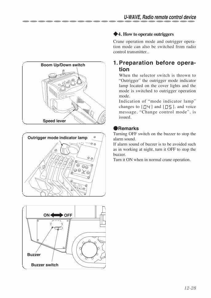
12-28
U-WAVE, Radio remote control device
◆4. How to operate outriggers
Crane operation mode and outrigger opera-tion mode can also be switched from radiocontrol transmitter..
1. Preparation before opera-tionWhen the selector switch is thrown to“Outrigger” the outrigger mode indicatorlamp located on the cover lights and themode is switched to outrigger operationmode.Indication of “mode indicator lamp”changes to [ ] and [ ], and voicemessage, “Change control mode”, isissued.
●RemarksTurning OFF switch on the buzzer to stop thealarm sound.If alarm sound of buzzer is to be avoided suchas in working at night, turn it OFF to stop thebuzzer.Turn it ON when in normal crane operation.
Outrigger mode indicator lamp
Boom Up/Down switch
Speed lever
ON OFF
Buzzer
Buzzer switch

12-29
2. OperationThrow the “selector switch” corresponding tothe outrigger number requiring control to thedesired operation side.Then pull the “speed lever” slowly whilekeeping the “selector switch” thrown to thedesired operation.As the “speed lever” is pulled slowly, the ver-tical cylinder starts to be operated graduallywith the engine running at a low (idling)speed, and pulling it further allows operatingspeed of the vertical cylinder becomes fasteras the engine speed is increased.
To extendTurn the switch to “Ext” to pull the “speedlever”. To retractTurn the switch to “Ret” to pull the “speedlever”. To stopReturn the ”selector switch” after the “speedlever” has been returned slowly.
●RemarksWhen the ”crane/outrigger operation modeselector switch” is turned to “outrigger” (out-rigger mode indicator lamp is being lit), nor-mal crane operation of “boom Up/Down”,“hook Up/Down”, ”telescoping boom”, ”slew-ing C.C.W./C.W.”, and ”storing hook” to beimpossible both in radio control transmitterand in manual control lever.
When the selector switch is thrown to“crane” voice message, “Change controlmode”, is issued and the mode is switched tocrane operation mode when the yellow lamplocated on the cover goes off.
Speed lever
Boom Ext/Ret switch
412 3
Switches in detail
STORE HOOK
(RET)
(START)
(EXT)(En. STOP)
MODE
EXT (RET)
RET (EXT)
SPEED
UP (RET)
DOWN (EXT)
UP (RET)
DOWN (EXT)
(En. START)
★If it has been selected to the mode (operation) to which is going to beselected, voice message will not be issued.
CAUTION
U-WAVE, Radio remote control device

12-30
U-WAVE, Radio remote control device
3. Closing operationWhen extending/retracting operation ofoutrigger through the radio control trans-mitter has been over, be sure to turn the“crane/outrigger operation mode selectorswitch” to “crane”.The outrigger mode indicator lamp goesoff and the buzzer stop sounding.Indication of the “mode indicator lamp”changes to either one of [ ] , [ ],[ ], or [ ], and voice message,“Change control mode”, is issued.
(Refer to section 12. o “Mode indicatorlamp” (on page 12-43) for mode indica-tion in detail.
Outrigger mode indicator lamp
Operation mode switch
★Take special care that your foot will not be stamped by outriggerwhile extending outriggers.
★Be sure to secure the hook in place while outriggers are being oper-ated.
CAUTION
Mode indicator lamp

12-31
◆5. Starting/Stopping engineThe engine can be started and stopped fromthe radio control transmitter.① When the engine key is turned ON, turn-
ing the selector switch to “slewingC.C.W.” with the “mode switch” beingdepressed allows the engine to start.
② Turning the selector switch to “slewingC.W.” with the ”mode switch” beingdepressed allows the engine to stop.
★When the engine is to be stopped for a long period of time, be sure toturn OFF the engine key on the side of crane.If the engine is being stopper by radio control transmitter for a longtime during which power to transmitter is turned ON, shortening the lifeof batteries results.
★The radio control system carries out system diagnosis automaticallyevery time when power is turned ON.Do not operate the crane while the system diagnosis is being carriedout.(Do not touch any one of switches and levers during this period.)If the crane is operated during system diagnosis, voice message,“Beep, Service remote control, Service remote control”, sounds and thecrane is turned into inoperable conditions.If this happened, depress the reset switch in the control box to carryout system diagnosis again.
★If the voice message, “Beep, Service remote control, Service remotecontrol”, is issued when turning ON the power despite the fact that thecrane has not been operated, ask a UNIC authorized service shop forrepair as failure in the radio control system is suspected.
CAUTION
Slewing C.W./C.C.W. switch
Mode switch
U-WAVE, Radio remote control device

12-32
U-WAVE, Radio remote control device
◆6. How to operate when engine speedbecomes unstable due to low temper-ature
When in winter season or when temperatureis too low, the engine speed may becomeunstable as viscosity of hydraulic oil increas-es.
In this case, switch the system to “low tem-perature operation mode” to allow the enginespeed to be stable.
1. Switching to low temperatureoperation modeDepress the “store hook” switch with the“swing C.C.W./C.W.“ switch turned to“C.C.W.”.Indication of the “mode indicator lamp”changes to [ ], and voice message,“Ping-pong, Change control mode,Change control mode”, is issued.(Indication will not change if the “modeindicator lamp” is showing [ ], [ ],or [ ].)
●RemarksWhen switching it to low temperature opera-tion mode, operation of the “store hook”switch before the “swing C.C.W./C.W.”selector switch has been actuated may allowvoice message, “Ping-pong, Secure liftinghook, Secure lifting hook”, to be issued.
Slewing C.C.W/C.W switch
Speed lever
Store Hookswitch
12-33
2. Resetting low temperature operation modeDepress the “store hook” switch with the “swing C.C.W./C.W.” switch turned to “C.W.”.Indication of “mode indicator lamp” changes to [ ] and voice message “Ping-pong,Change control mode, Change control mode”, is issued.(Indication will not change if the “mode indicator” is showing [ ], [ ], or [[ ].)
In addition, the low temperature operation mode is to be reset automatically, even whenoperation illustrated above has not been carried out, after approx. 10 minutes from the timewhen it has been switched to the “low temperature operation mode”.The voice message “Ping-pong, Change control mode, Change control mode”, is issuedat this time.
●RemarksResponse of the crane functions becomes slower when operated on low temperature operationmode.In normal case, operate the crane after warming-up for a while to raise temperature of hydraulicoil.
Under extreme low temperature, crane operation may still be unstable even after the system hasbeen switched to the “low temperature operation mode”.In this case take measures such as by carrying out warm-up operation to raise temperature ofhydraulic oil or by using hydraulic oil suitable for extreme low temperature.
★If viscosity of hydraulic oil is too high at a low temperature, exces-sive load will be imposed on hydraulic pumps which may cause dam-age to them.In order to avoid this, be sure to carry out warming-up to raise tempera-ture of hydraulic oil to an appropriate temperature to operate the crane.
CAUTION
◆7. Closing crane operationAfter completion of the crane work, turn OFFthe starter switch to shut off power to thecrane after the boom, the hook, and the out-riggers have been stored in their respectivepositions.
U-WAVE, Radio remote control device

12-34
U-WAVE, Radio remote control device
◆1. When to replace batteries
★When the power lamp of trans-mitter starts blinking, replace thebatteries as early as possible.
Leaving them as they were maycause the liquid in the batteries toleak.★In case where leakage of bat-tery liquid is found, wipe it offthe battery holder and the batterycase thoroughly to put new bat-teries in it.
CAUTION
●Check the “power lamp” for lighting withthe “speed selector switch” on the transmitterdepressed.
① Continuous lighting: Radio control trans-mitter can be used.
② Blinking in low frequency (a flash everysecond): It allows the radio control trans-mitter to be used for about 1 hour after theblinking has started.Replace the batteries as early as possibleas they are close to running out.
③ Blinking in high frequency (a flash every0.1 second): The radio control transmittercan not to be used as the batteries haverun out.
④ No lighting: The radio control transmittercan not to be used as the batteries havecompletely run out.
●If the “power lamp” blinks slow as in con-dition ② above, following voice message,“Ping-pong, Low transmitter battery, Lowtransmitter battery”, is issued.The trouble lamp on the receiver blinks inred, and the “mode indicator lamp” shows[ ] in blinking.
Speed selector switch
Battery cover
Battery
Battery case
Hook
Power lamp
uHow to replace batteries of transmitter

12-35
◆2. Battery to be employeda size AAA battery: 4 piecesUse alkaline-type battery. (Manganese-type battery has a short servicelife.)
●RemarksAbout the use of rechargeable bat-teriesAlthough UNIC recommends the use of alka-line type battery in the radio control transmit-ter, other rechargeable batteries such as nick-el-hydrogen type and nickel-cadmium typemay also be used.Pay attention to the following when arechargeable battery is used:
• Message suggesting replacement of batterymay not be issued.Be sure to prepare alkaline-type batterieswhen operating the crane through radioremote control device because rechargeablebatteries tend to become inoperable sudden-ly.
• In some cases, service life of rechargeablebattery may become shorter than that ofalkaline battery in accordance with thecapacity.
• There is a disadvantage such as memoryeffect comparing with alkaline-type battery.
★Do not mix up batteries of oldand new, of different manufactur-ers, or of different types.
CAUTION
U-WAVE, Radio remote control device
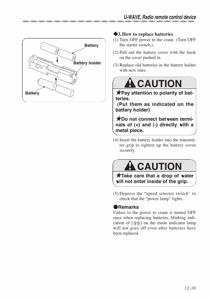
12-36
U-WAVE, Radio remote control device
◆3. How to replace batteries(1) Turn OFF power to the crane. (Turn OFF
the starter switch.).
(2) Pull out the battery cover with the hookon the cover pushed in.
(3) Replace old batteries in the battery holderwith new ones.
★Pay attention to polarity of bat-teries.(Put them as indicated on the
battery holder)
★Do not connect between termi-nals of (+) and (-) directly with ametal piece.
CAUTION
(4) Insert the battery holder into the transmit-ter grip to tighten up the battery coversecurely.
★Take care that a drop of waterwill not enter inside of the grip.
CAUTION
(5) Depress the “speed selector switch” tocheck that the “power lamp” lights.
●RemarksUnless to the power to crane is turned OFFonce when replacing batteries, blinking indi-cation of [ ] on the mode indicator lampwill not goes off even after batteries havebeen replaced.
Battery
Battery
Battery holder

12-37
iDaily checks, trouble inspection◆1. Daily checks
For cranes with radio remote control device, you are requested to inspect your crane for follow-ing items as well as carry out daily checks on your crane (read operator’s manual of UNICcrane concerned for detail).Check that;
1. Each enclosure of transmitter, receiver, and control box has not been damaged.If the enclosure has been damaged, repair it immediately because moisture and/or dustentered through the break may cause a failure to electronic parts inside and cause incorrectoperation of the crane concerned.
2. The stay on the transmitter has not been broken or deformed.The transmitting antenna is built in the stay.If break or remarkable deformation is found in the stay, replace or repair it as soon as possi-ble because it may cause radio interference.
3. Switches and control levers on the radio control transmitter make a smooth operation.Using the remote control transmitter with dust, dirt, and mud being stuck on may lead tofailure especially in operation of switches and/or control levers.Wipe them off with a piece of cloth after use.If any of the selector switches fails to function correctly due to contamination, ask a UNICauthorized service shop for cleaning.
★Never try disassembly or alteration of the transmitter, the receiver,and the control box.★Electric system is very sensitive to moisture. Do not wash the transmitter, the receiver, and the control box with waterdirectly.
CAUTION
U-WAVE, Radio remote control device

12-38
U-WAVE, Radio remote control device
◆2. Check lamps (Radio control receiver)Check lamps are mounted on the radio receiver, and they light as follows when it is in normaloperating condition:
● Power lampWhen energizing the crane by turning ON the starter switch, it blinks in green.
● Receiving lampWhen the receiver is received radio wave transmitted from the transmitter correctly, it blinks ingreen.
● Interference lampIf it lights in red when power to the transmitter is turned OFF, it indicates that the receiver isreceiving radio wave from outside. If it lights in red when power to the transmitter is turned OFF, response time during radio con-trol operation may become longer to a certain extent.When radio control operation is initiated from the state where the power to transmitter is turnedOFF, the “interference lamp” may light for a moment but it is not a fault.
● Error lampIt blinks in red when something is wrong with the radio control transmitter/receiver.It also blinks in red when batteries in the transmitter have been run out.
Interference (Lights)
Receiver
Interference lamp
Receiving lamp
Error lamp
Power lampPower (Blinks)
Error (Blinks)
Receiving (Blinks)
Check lamp

12-39
◆3. Trouble inspectionIf a trouble is found in the radio remote control device, check the following then contact thenearest UNIC authorized service shop.Check if:
① Crane is controlled by manual levers.
② The “power lamp” on the transmitter lights. If it blinks or does not light, replace the batter-ies in the transmitter.
③ Switches and control levers on the transmitter make a correct operation.
④ The stay on the transmitter (antenna is built in) has not been broken or deformed.
⑤ The “mode indicator lamp” in the control box lights and the “power lamp” on the receiverblinks in green when power to the control box is turned ON.If the “mode indicator lamp” blinks, refer to section “18. Mode indicator lamp” (onpage18-1).
If the “error lamp” on the receiver blinks in red, turn OFF the power once and turn it ON again(turn ON the starter switch again).If blinking of “error lamp” persists, repair is needed as the radio remote control device is in fail-ure.
U-WAVE, Radio remote control device

12-40
U-WAVE, Radio remote control device
◆4. How to make an emergency stopIn case of emergency such as that the crane does not stop operation or the engine will not returnto idling speed even if no crane operation has been made, depress the “EMERGENCY” switchon the switch panel. This makes the crane and the engine to stop operation forcibly.
★When releasing the emergency stop switch, release it while no craneoperation is being carried out.Releasing the emergency stop switch while operating the crane allowsthe crane to make an abrupt movement that is very dangerous.
WARNING
●How to make an emergency stopfor the crane and reset it
Depress the “EMERGENCY” stop switch onthe switch panel of crane body.The switch is held pushed in allowing theengine to stop operation.When the switch is held pushed in, the enginecannot be re-started.Rotate the emergency stop switch clockwisein arrow direction to return to its originalstate to release the switch.
●RemarksWhen the emergency stop is reset by turn-ing the “EMERGENCY” stop switchclockwise after the crane has been stoppedby depression of “EMERGENCY” stopswitch, the engine speed may increase in amoment which is not abnormal.
When the crane is operated with the“EMERGENCY” stop switch held pushedin, voice message, “Beep. Service remoteService remote control” may be issued orthe mode indicator lamp may show incor-rect indication.
Emergency stop switch
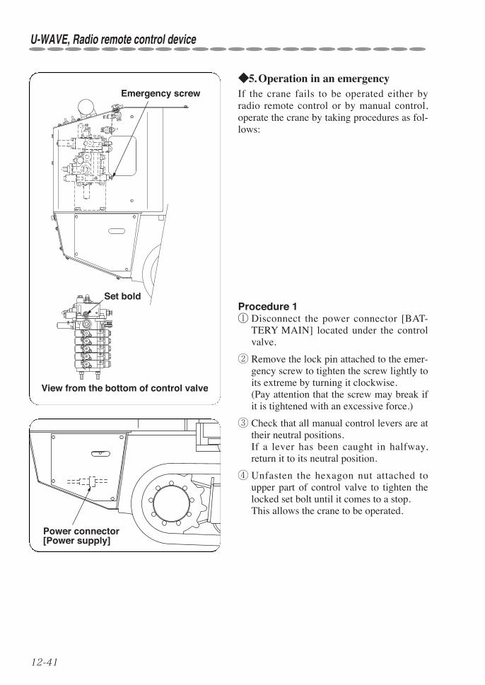
12-41
◆5. Operation in an emergencyIf the crane fails to be operated either byradio remote control or by manual control,operate the crane by taking procedures as fol-lows:
Procedure 1① Disconnect the power connector [BAT-
TERY MAIN] located under the controlvalve.
② Remove the lock pin attached to the emer-gency screw to tighten the screw lightly toits extreme by turning it clockwise.(Pay attention that the screw may break ifit is tightened with an excessive force.)
③ Check that all manual control levers are attheir neutral positions.If a lever has been caught in halfway,return it to its neutral position.
④ Unfasten the hexagon nut attached toupper part of control valve to tighten thelocked set bolt until it comes to a stop.This allows the crane to be operated.
Power connector [Power supply]
U-WAVE, Radio remote control device
View from the bottom of control valve
Set bold
Emergency screw
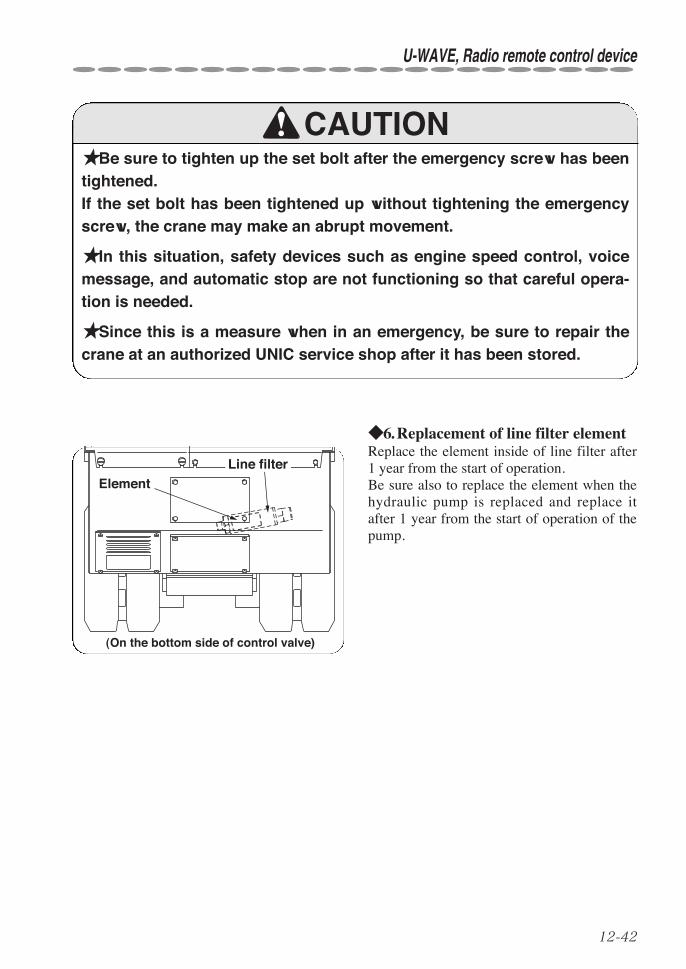
12-42
U-WAVE, Radio remote control device
★Be sure to tighten up the set bolt after the emergency screw has beentightened.If the set bolt has been tightened up without tightening the emergencyscrew, the crane may make an abrupt movement.
★In this situation, safety devices such as engine speed control, voicemessage, and automatic stop are not functioning so that careful opera-tion is needed.
★Since this is a measure when in an emergency, be sure to repair thecrane at an authorized UNIC service shop after it has been stored.
CAUTION
◆6. Replacement of line filter elementReplace the element inside of line filter after1 year from the start of operation.Be sure also to replace the element when thehydraulic pump is replaced and replace itafter 1 year from the start of operation of thepump.
ElementLine filter
(On the bottom side of control valve)

13-1
13. MAINTENANCE AND INSPECTION OF CARRIER
★Caution signboardBe sure to hang a “caution signboard” such as on control levers whileeither maintenance or inspection is being carried out, and do not tryoperating the crane.
★Be sure to replace consumable items according to the replacementcriteria.Failure to observe the replacement as specified may cause a break-down and warranty will not be given even if it is within the period to beapplied.
★When a part needs to be replaced or anything abnormal is found,contact a UNIC service shop for consultation or for inspection or askrepair as soon as possible.
WARNING

13-2
MAINTENANCE AND INSPECTION OF CARRIER
In order to secure safety in crane operation and to improve working efficiency, be sure toinspect each part of the carrier according to the table as follows:
q Inspection before operation
★Since the machine uses gasoline as fuel, check the hose for crack andconnections for tightness if you have a smell of gasoline around theengine.If fuel leaked in the vicinity of engine and muffler which are very hot maycause a fire.Wipe it off completely.
★Be sure to stop the engine, and store the boom and the outriggersbefore carrying out maintenance and inspection.
★A fire source such as smoking cigarette in mouth is strictly prohibited.
★Do not start maintenance and inspection immediately after the enginehas been stopped.Carry it out after the engine and the heated parts have been cooled down.
★Perform monthly and annual inspection according to “Voluntaryinspection table” in the warranty which is provided separately.
★Keep the crawler crane in good condition so that it will be alwaysready for normal operation.
Device Servicing item Device Servicing item
Engine
Fuel leakageRemaining fuel quantityEngine oil quantity/Filling upBattery electrolytic solutionlevel checkUnusual vibration, NoiseLoose bolt, Broken bolt
Hydraulic oiltank
Oil leakage, Oil quantity,Filling up
Interlock forc r ane -c r awllever
Function
Crawling lever Slack, Travel
Wheel sprocket Loose bolt
Rubber crawler Crack, Damage, Tension
Frame Bend, Crack, Deformation
Truck roller Loose nut, Oil leakage
WARNING
CAUTION

13-3
●When refueling, remove the cap and neverfail to put the strainer of fuel tank in orderto prevent water and dust from entering thetank.Fuel tank capacity: 6 liters
♦1. Check for remaining fuel quantity/ Draining water
●When draining fuel in order to transportthe crane and store it for long period oftime, remove the strainer cup in the fuelcock to extract it.
● In addition, clean up the filter net with thefuel strainer cup removed.
★Fuel (gasoline) is highly inflammable.Do not smoke and bring a fire source close to the fuel when refueling anddraining sediment.
★Wipe up spilled fuel thoroughly after refueling as it may cause the fire.
WARNING
Fuel tank cap
Fuel cock
Strainer cup
Filter net
MAINTENANCE AND INSPECTION OF CARRIER
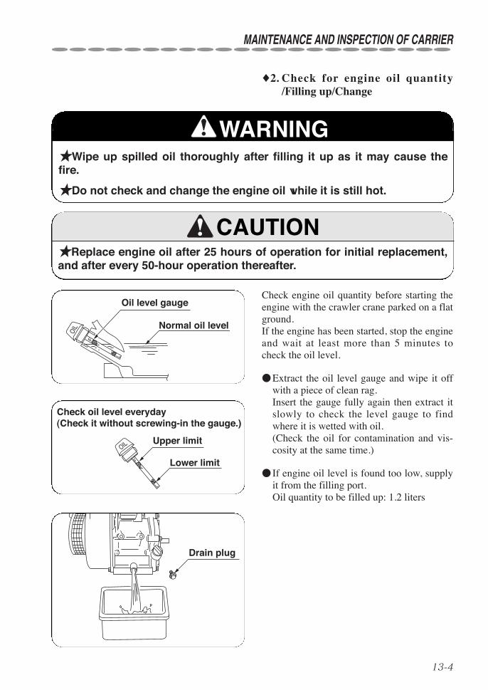
13-4
MAINTENANCE AND INSPECTION OF CARRIER
Check engine oil quantity before starting theengine with the crawler crane parked on a flatground.If the engine has been started, stop the engineand wait at least more than 5 minutes tocheck the oil level.
●Extract the oil level gauge and wipe it offwith a piece of clean rag.Insert the gauge fully again then extract itslowly to check the level gauge to findwhere it is wetted with oil.(Check the oil for contamination and vis-cosity at the same time.)
● If engine oil level is found too low, supplyit from the filling port.Oil quantity to be filled up: 1.2 liters
♦2. Check for engine oil quantity/Filling up/Change
★Wipe up spilled oil thoroughly after filling it up as it may cause thefire.
★Do not check and change the engine oil while it is still hot.
★Replace engine oil after 25 hours of operation for initial replacement,and after every 50-hour operation thereafter.
WARNING
CAUTION
L
F
OIL Normal oil level
Oil level gauge
L
F
OIL
Check oil level everyday (Check it without screwing-in the gauge.)
Lower limit
Upper limit
Drain plug

13-5
●Check that the battery solution level issomewhere between the upper and thelower limit lines with the battery placedlevel.
● If solution level is found below the lowerlimit line, remove the cap to fill it up withdistilled water (It is available at a gas sta-tion.)Tighten the caps securely after the waterhas been filled.
●Pay attention that the crane body may beeroded by the battery solution due to leak-age during operation if solution levelexceeds beyond the upper limit line.
★Gas evaporated from the battery solution is inflammable.Do not bring a fire source close to the battery during battery mainte-nance.And, be sure to disconnect the negative (-) side of battery cord.
★Battery electrolytic solution contains sulfuric acid so that you may beblinded or burned by the solution when your eye, skin, or clothes wasstained with the solution.Wear safety goggles and rubber gloves as a protective measures whenworking at battery.If the solution stuck to your skin or clothes, wash it away with plenty ofwater immediately.In case where it entered into your eye accidentally, see a doctor fortreatment.
★When the crane will not be operated for a long period of time such asin being stored, charge the battery as follows:
Warm season (May to September) Once a monthCold season (October to April) Once every 2nd month
♦3. Check for battery electrolytic solu-tion level / Filling up
Upper limit line
Lower limit line
WARNING
MAINTENANCE AND INSPECTION OF CARRIER
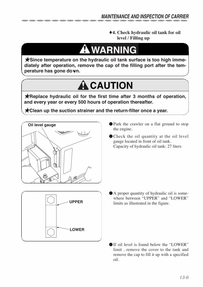
13-6
MAINTENANCE AND INSPECTION OF CARRIER
♦4. Check hydraulic oil tank for oillevel / Filling up
★Since temperature on the hydraulic oil tank surface is too high imme-diately after operation, remove the cap of the filling port after the tem-perature has gone down.
★Replace hydraulic oil for the first time after 3 months of operation,and every year or every 500 hours of operation thereafter.
★Clean up the suction strainer and the return-filter once a year.
●Park the crawler on a flat ground to stopthe engine.
●Check the oil quantity at the oil levelgauge located in front of oil tank.Capacity of hydraulic oil tank: 27 liters
●A proper quantity of hydraulic oil is some-where between “UPPER” and “LOWER”limits as illustrated in the figure.
● If oil level is found below the “LOWER”limit , remove the cover to the tank andremove the cap to fill it up with a specifiedoil.
WARNING
CAUTION
Oil level gauge
UPPER
LOWER
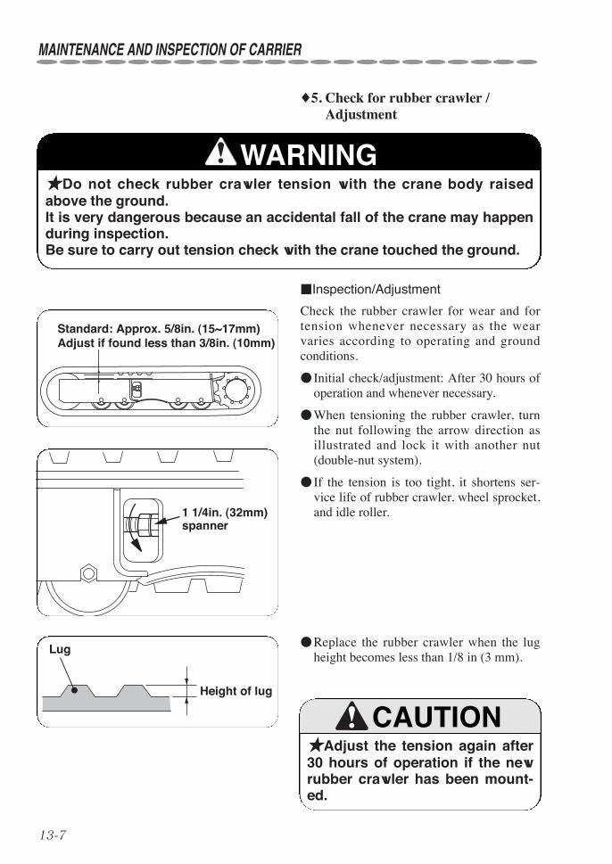
13-7
♦5. Check for rubber crawler /Adjustment
★Do not check rubber crawler tension with the crane body raisedabove the ground.It is very dangerous because an accidental fall of the crane may happenduring inspection.Be sure to carry out tension check with the crane touched the ground.
■Inspection/Adjustment
Check the rubber crawler for wear and fortension whenever necessary as the wearvaries according to operating and groundconditions.
● Initial check/adjustment: After 30 hours ofoperation and whenever necessary.
●When tensioning the rubber crawler, turnthe nut following the arrow direction asillustrated and lock it with another nut(double-nut system).
● If the tension is too tight, it shortens ser-vice life of rubber crawler, wheel sprocket,and idle roller.
★Adjust the tension again after30 hours of operation if the newrubber crawler has been mount-ed.
Lug
Height of lug
WARNING
CAUTION
●Replace the rubber crawler when the lugheight becomes less than 1/8 in (3 mm).
Standard: Approx. 5/8in. (15~17mm)Adjust if found less than 3/8in. (10mm)
1 1/4in. (32mm) spanner
MAINTENANCE AND INSPECTION OF CARRIER
13-8
MAINTENANCE AND INSPECTION OF CARRIER
★Do not crawl over lying rocks or stones with sharp edges.
★Do not change direction where there is a difference in ground level.
★Do not make a quick change of direction as it may cause the wheelsto go off the rubber crawler.
★Do not operate the crane on a ground being heated to the tempera-ture of more than 140°F (60°C.)
★Do not stain the rubber crawler with oils such as fuel, hydraulic oil,grease, and the other oil.
★Do not operate the crane at a place where salt content is abundant.
★When storing the crane for long period of time, store it indoors whereit will not be exposed to the ray of the sun or to the rain directly.
CAUTION
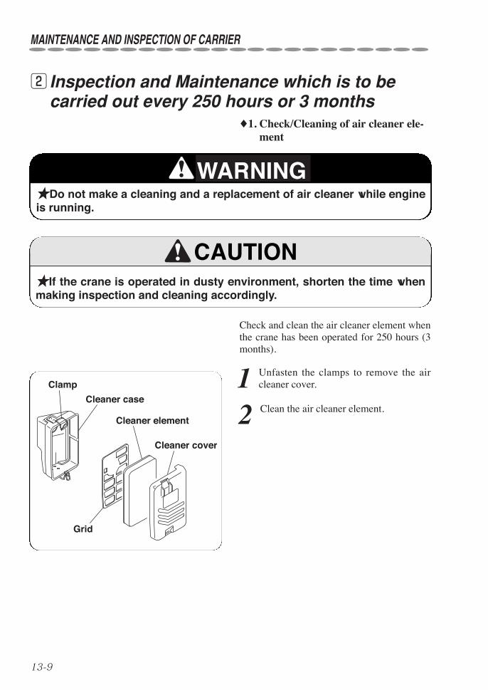
13-9
w Inspection and Maintenance which is to becarried out every 250 hours or 3 months
♦1. Check/Cleaning of air cleaner ele-ment
★Do not make a cleaning and a replacement of air cleaner while engineis running.
★If the crane is operated in dusty environment, shorten the time whenmaking inspection and cleaning accordingly.
Check and clean the air cleaner element whenthe crane has been operated for 250 hours (3months).
1 Unfasten the clamps to remove the aircleaner cover.
2 Clean the air cleaner element.
WARNING
CAUTION
Cleaner cover
Clamp
Cleaner case
Grid
Cleaner element
MAINTENANCE AND INSPECTION OF CARRIER

13-10
MAINTENANCE AND INSPECTION OF CARRIER
♦2. Check oil quantity in the reductiongears of crawling motor/Filling up(Change oil every 1,000 hours)
★Do not rush to work as each section of crawling devices is heated toa high temperature immediately after the crane operation.Work after temperature of crawling devices has cooled down.
★Pressure may be remained inside of the reduction gears of crawlingmotor.Unfasten the filling port plug by 2~3 turns slowly to release the internalpressure and then remove the plug.An abrupt removal of the plug may cause the plug to pop out or the oilto spurt out which is dangerous.Do not turn your body or face toward the plug.
1 Park the crane on a flat ground.
2 Position 2 (two) plugs at the end ofreduction gears of crawling motor as
illustrated in the figure, “position for inspec-tion”, and stop the engine.
3 Unfasten the filling port plug slowly tobleed air.
4 Remove the filling port plug and oilquantity is correct if oil flows out of the
filling port.If oil quantity is insufficient, fill it with theoil specified.
5 Check the sealing of each plug, replaceit with new seal if it is found damaged.
6 Put the plug on the filling port and tight-en it.
WARNING
Filling port
Drain port
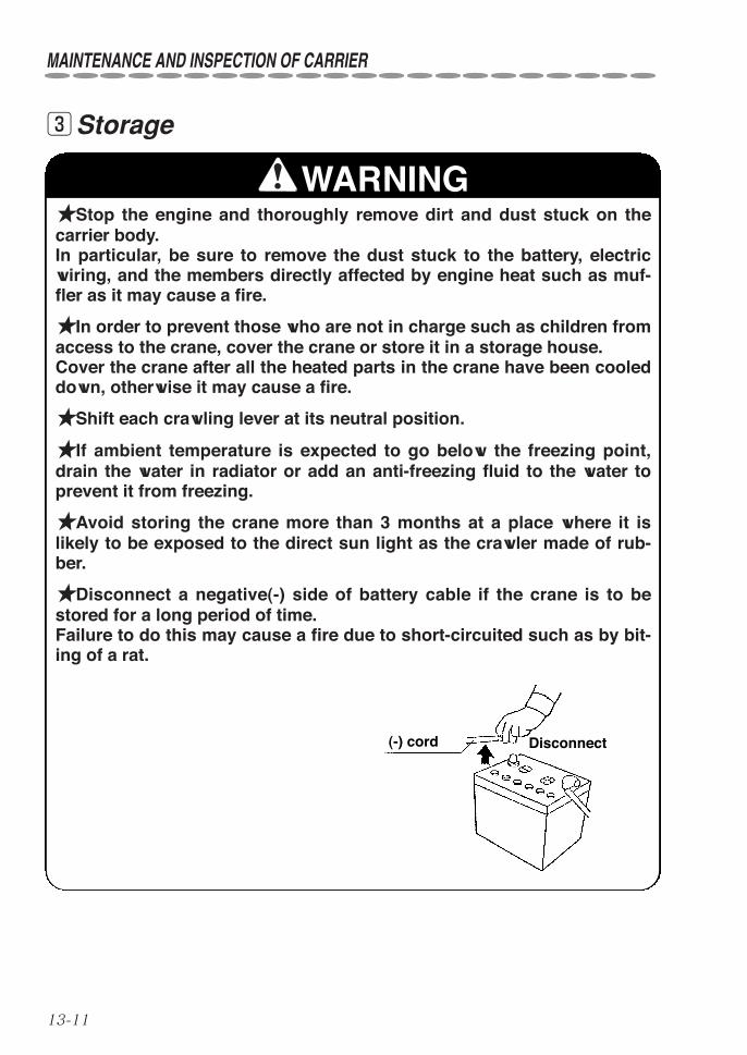
13-11
eStorage
★Stop the engine and thoroughly remove dirt and dust stuck on thecarrier body.In particular, be sure to remove the dust stuck to the battery, electricwiring, and the members directly affected by engine heat such as muf-fler as it may cause a fire.
★In order to prevent those who are not in charge such as children fromaccess to the crane, cover the crane or store it in a storage house.Cover the crane after all the heated parts in the crane have been cooleddown, otherwise it may cause a fire.
★Shift each crawling lever at its neutral position.
★If ambient temperature is expected to go below the freezing point,drain the water in radiator or add an anti-freezing fluid to the water toprevent it from freezing.
★Avoid storing the crane more than 3 months at a place where it islikely to be exposed to the direct sun light as the crawler made of rub-ber.
★Disconnect a negative(-) side of battery cable if the crane is to bestored for a long period of time.Failure to do this may cause a fire due to short-circuited such as by bit-ing of a rat.
(-) cord
WARNING
Disconnect
MAINTENANCE AND INSPECTION OF CARRIER

13-12
rFitting safety covers
★Be sure to fit the safety covers removed during inspection and main-tenance where they were fitted originally.Otherwise, it is very dangerous because uncovered rotating membersand heated parts may cause injury.
tMaintenance and inspection of engineCarry out the maintenance and inspection of engine according to “Instruction manual forengine”.
WARNING
MAINTENANCE AND INSPECTION OF CARRIER
14-1
14. MAINTENANCE AND INSPECTION OF CRANE
★Caution signboardBe sure to hang a “caution signboard” such as on control levers whileeither maintenance or inspection is being carried out, and do not tryoperating the crane.
★Be sure to replace consumable items according to the replacementcriteria.Failure to observe the replacement as specified may cause a break-down and warranty will not be given even if it is within the period to beapplied.
★When a part needs to be replaced or anything abnormal is found,contact a UNIC service shop for consultation or for ask inspection orrepair as soon as possible.
WARNING

14-2
MAINTENANCE AND INSPECTION OF CRANE
In order to secure safe operation and improve working efficiency, be sure to inspect daily eachpart of the crane according to the table as follows:
q Inspection before operation
★Perform monthly and annual inspection according to “Voluntaryinspection table” in the warranty which is provided separately.
★Keep the crawler crane in good condition so that it will be alwaysready for normal operation.
Device Servicing item
Pump
Tightness of eachmountingOil leakageUnusual noise
Hydraulicoil tank
Oil levelOil leakage
Outriggers
Natural descentFunctionDeformation DamageOil leakageCracks
Hoistingwinch
FunctionBraking functionIrregular winding
Slewingdevice
FunctionOil leakage
Derrickingboom
FunctionOil leakageMounting of foot-pin
Device Servicing item
Loadmeter
Oil leakageFunction
HookRotation of hookFunction of retain-ing mechanism
Wire ropeDamageCondition of rope-end
Overwindingalarm
FunctionAlarm sound
Interlockfor crane-crawllever
Crane will not func-tion when the leveris shifted to“crawl”.Carrier will notcrawl when thelever is shifted to“crane”.
Device Servicing item
Turn overpreventiondevice
Refer to page 9-11Inspection beforestarting operationDaily inspection Trouble inspectionAlarm spectionInspection for auto-matic stopCheck wiring fordamageCheck sensor mount-ing for tightness
Frame
Mounting of cranebodyCracksTightness of boltsMissing bolt
Slingingimplements
Items necessary forcrane operation areprovided
Automaticstoringdevice forhook
Function of automat-ic stop and storingoperation
Automaticstop forleavingminimumwire rope
Further unwindingstops automaticallywhen remainingwire rope on thedrum comes to 3turns.
Telescopingboom
FunctionOil leakageDeformationCracksMounting of fixingpin
Warninghorn
Function
Piping,Hydraulichose
Oil leakageDamage
CAUTION

14-3
Keep the crane clean at any time.Sands and fine dusts may cause an abnormal wear .Do not wash the crane by splashing highly pressurized water to prevent it from entering into theelectric system by which may cause malfunction of the crane.
When the slewing device makes an unusualnoise while operating or crawling the crane,or when a gap is created on the mounting sur-face, contact a UNIC authorized service shopfor inspection and/ for repair.
wCleaning
e Inspection of bolts mounting slewing bearings
★Break of the bolts mountingslewing bearings may invite anaccident such as overturn anddestruction of the crane.Check the mounting bolts (outerring side) for tightness onceevery 6 months.
MAINTENANCE AND INSPECTION OF CRANE
CAUTION
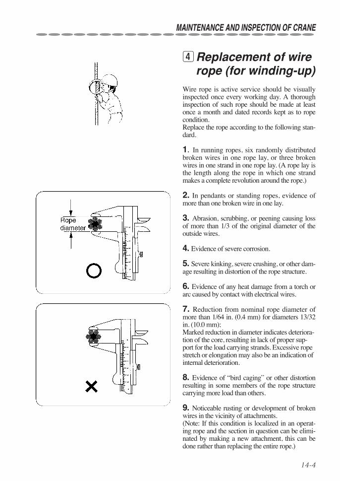
14-4
MAINTENANCE AND INSPECTION OF CRANE
Wire rope is active service should be visuallyinspected once every working day. A thoroughinspection of such rope should be made at leastonce a month and dated records kept as to ropecondition.Replace the rope according to the following stan-dard.
1. In running ropes, six randomly distributedbroken wires in one rope lay, or three brokenwires in one strand in one rope lay. (A rope lay isthe length along the rope in which one strandmakes a complete revolution around the rope.)
2. In pendants or standing ropes, evidence ofmore than one broken wire in one lay.
3. Abrasion, scrubbing, or peening causing lossof more than 1/3 of the original diameter of theoutside wires.
4. Evidence of severe corrosion.
5. Severe kinking, severe crushing, or other dam-age resulting in distortion of the rope structure.
6. Evidence of any heat damage from a torch orarc caused by contact with electrical wires.
7. Reduction from nominal rope diameter ofmore than 1/64 in. (0.4 mm) for diameters 13/32in. (10.0 mm);Marked reduction in diameter indicates deteriora-tion of the core, resulting in lack of proper sup-port for the load carrying strands. Excessive ropestretch or elongation may also be an indication ofinternal deterioration.
8. Evidence of “bird caging” or other distortionresulting in some members of the rope structurecarrying more load than others.
9. Noticeable rusting or development of brokenwires in the vicinity of attachments.(Note: If this condition is localized in an operat-ing rope and the section in question can be elimi-nated by making a new attachment, this can bedone rather than replacing the entire rope.)
rReplacement of wirerope (for winding-up)
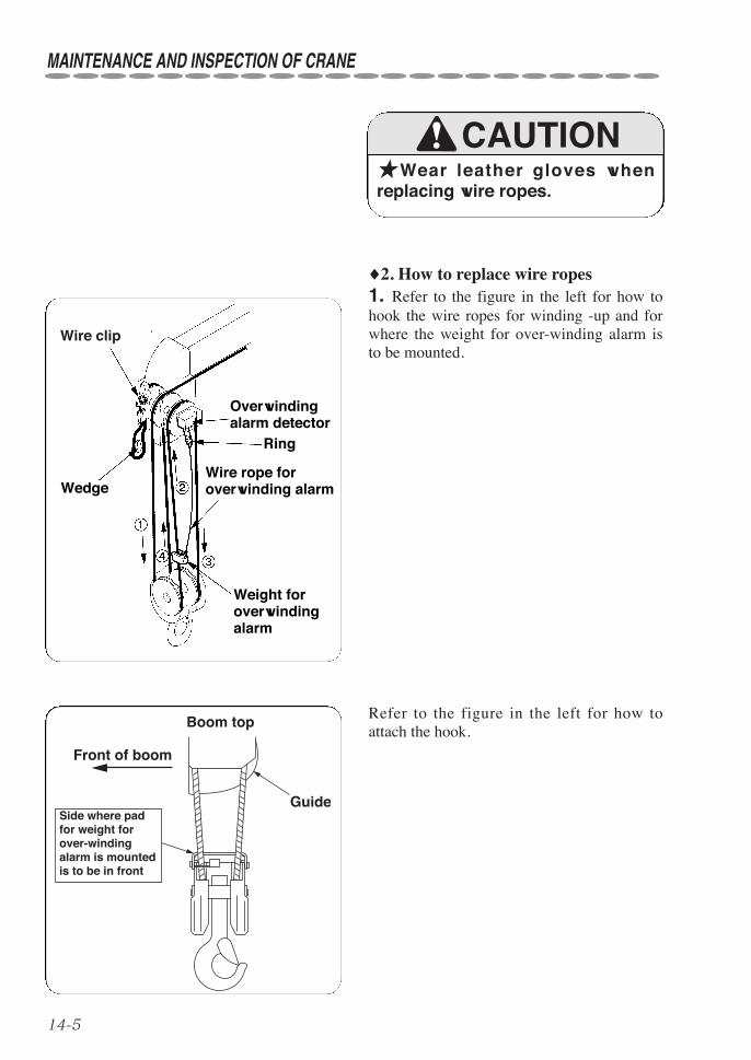
14-5
Boom top
Front of boom
GuideSide where pad for weight for over-winding alarm is mounted is to be in front
♦2. How to replace wire ropes1. Refer to the figure in the left for how tohook the wire ropes for winding -up and forwhere the weight for over-winding alarm isto be mounted.
Refer to the figure in the left for how toattach the hook.
MAINTENANCE AND INSPECTION OF CRANE
Wire clip
Wedge
Overwindingalarm detector
Ring
Wire rope foroverwinding alarm
Weight foroverwindingalarm
★Wear leather gloves whenreplacing wire ropes.
CAUTION

14-6
MAINTENANCE AND INSPECTION OF CRANE
2in. (50mm)
1 5/8in. (40mm)a
Wire rope end
Notch
Wire clip
(Pay attention to mounting direction)
Arrow markWedge
(Wire rope diameter: 5/16in. (8mm))
Projection on upper part of wire socket
Stopper
If rope end is left by more than 1 5/8 in (40mm) (as “a” illustrated above), rope end is visible through this hole. If not, adjust the distance of rope end.
Pass the pin through and tighten it with bolt securely.
2. How to fix wire rope end① When passing the wire rope end throughthe wire socket, be sure to pass it as indicatedby the arrow mark on the socket.If it is passed from the opposite direction,service life of wire rope becomes shorter asthe wire rope is kept bent all the time.
② Do not forget to mount the wedge and thewire clip as illustrated in the figure in the left.Leave the wire rope end to allow a distancefrom the notch to the rope end by more than40mm as illustrated in the figure as “a”.
③ Pass the pin through with the wire socketheld with your hand and tighten it with thebolt securely.
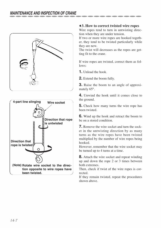
14-7
4-part line slinging Wire socket
Direction that rope is untwisted
Direction that rope is twisted
(Note) Rotate wire socket to the direc-tion opposite to wire ropes have been twisted.
♦3. How to correct twisted wire ropesWire ropes tend to turn in untwisting direc-tion when they are under tension.If two or more wire ropes are hooked togeth-er, they tend to be twisted particularly whilethey are new.The twist will decreases as the ropes are get-ting fit to the crane.
If wire ropes are twisted, correct them as fol-lows:
1. Unload the hook.
2. Extend the boom fully.
3. Raise the boom to an angle of approxi-mately 65°.
4. Unwind the hook until it comes close tothe ground.
5. Check how many turns the wire rope hasbeen twisted.
6. Wind up the hook and retract the boom tobe on a stored condition.
7. Remove the wire socket and turn the sock-et in the untwisting direction by as manyturns as the wire ropes have been twistedmultiplied by the number of wire ropes beinghooked. However, remember that the wire socket maybe turned up to 4 turns at a time.
8. Attach the wire socket and repeat windingup and down the rope 2 or 3 times betweenboth extremes.Then, check if twist of the wire ropes is cor-rected.If they remain twisted, repeat the proceduresshown above.
MAINTENANCE AND INSPECTION OF CRANE
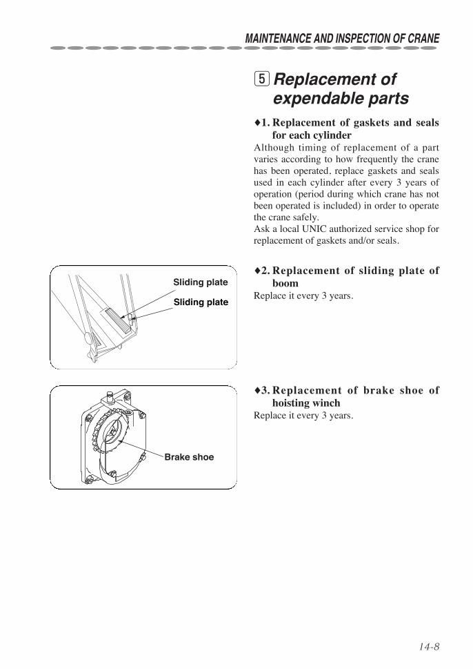
14-8
♦1. Replacement of gaskets and sealsfor each cylinder
Although timing of replacement of a partvaries according to how frequently the cranehas been operated, replace gaskets and sealsused in each cylinder after every 3 years ofoperation (period during which crane has notbeen operated is included) in order to operatethe crane safely.Ask a local UNIC authorized service shop forreplacement of gaskets and/or seals.
tReplacement ofexpendable parts
♦2. Replacement of sliding plate ofboom
Replace it every 3 years.
♦3. Replacement of brake shoe ofhoisting winch
Replace it every 3 years.
MAINTENANCE AND INSPECTION OF CRANE
摺動板
摺動板
Brake shoe
Sliding plate
Sliding plate

15-1
15. WATER SUPPLY AND LUBRICATION TO CARRIER
★Be sure to stop the engine, and store the boom and the outriggersbefore carrying out filling/replacing lubricant and/or fuel.
★A fire source such as smoking cigarette in mouth is strictly prohibited.
★Do not rush to start maintenance and inspection as the engine and themembers close to the engine is heated to a high temperature immediatelyafter the engine has been stopped.
Lubricate according to “Lubrication chart”and keep the following instructions in mindwhen carrying out lubrication.
1. Clean filling ports and grease nipples thor-oughly before carrying out lubrication.
2. Always supply new lubricant and preventdusts from entering inside.
3. When supplying grease into each greasenipple, be sure to inject it until old grease isforced out of it.
qPrecaution whencarrying out lubrica-tion
★In order to ensure smoothoperation of each part of thecrane, minimum wear, and longerservice life, be sure to supplylubricant as well as hydraulic oilwhich is indispensable to drivehydraulic equipment.
★Warranty will not be given,even if it is within the period tobe applied, for failure to observethe replacement of lubricant asspecified.
WARNING
CAUTION

15-2
WATER SUPPLY AND LUBRICATION TO CARRIER
wList of recommended lubricant♦1. Use the engine oils as below:
♦2. Use the recommended grease for lubrication as below.Chassis greaseUse NLGI No. 2 grade for most temperatures.Use NLGI No. 1 grade for extremely low temperatures.
♦3. Use the fuel as specified below.Use only automobile non-leaded gasoline
10W40
10W30
5W20
-30 -20 -10 0 10 20 30 40°C
(-22 -4 14 32 50 68 86 104°F)
Multi-grade
The selection of engine oil is very important to a engine.If an unsuitable oil is used, or oil change is neglected, it may result in damage, and ashorter engine life.Use oils that meet API Engine Service Classification CD.
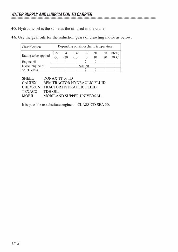
15-3
WATER SUPPLY AND LUBRICATION TO CARRIER
♦5. Hydraulic oil is the same as the oil used in the crane.
♦6. Use the gear oils for the reduction gears of crawling motor as below:
-30 -20 -10 0 10 20 30°C(-22 -4 14 32 50 68 86°F)
SAE30Engine oil Diesel engine oil of CD class
Classification Depending on atmospheric temperature
Rating to be applied
SHELL : DONAX TT or TDCALTEX : RPM TRACTOR HYDRAULIC FLUIDCHEVRON : TRACTOR HYDRAULIC FLUIDTEXACO : TDH OILMOBIL : MOBILAND SUPPER UNIVERSAL.
It is possible to substitute engine oil CLASS-CD SEA 30.

15-4
eFilling water and lubrication chart
Service interval Where to lubricate No. ofpart Lubricant Tool
Initial: Replace after 25 hours After : Replace every 50 hours
① Engine 0.3 gal.(1.2 liters)
1 Engine oil
Initial : 30 hours, Whenever nec-essary
② Tension adjustment ofrubber crawler
21 1/4 gal.(32mm)spanner
Fuel Gasoline
Fuel tank capacity 1.6 gal. (6 liters)
Initial: Replace after 3 months After : Replace once a year orevery 500 hours
③ Hydraulic oil tank 7.1 gal.(27 liters)
1 Hydraulic oil
Replace every 1000 hours④ Reduction gears of crawl-
ing motor 0.1 gal.(0.33 liters)
2 (Right/Left)
Diesel engine oil
Refer to “MAINTENANCE AND INSPECTION OF CARRIER” for replacement procedures.
WATER SUPPLY AND LUBRICATION TO CARRIER
③ ② ④ ①

16-1
Lubricate according to “Lubrication chart”and keep the following instructions in mindwhen carrying out lubrication.
1. Clean filling ports and grease nipples thor-oughly before carrying out lubrication.
2. Always supply new lubricant and preventdusts from entering inside.
3. When supplying grease into each greasenipple, be sure to inject it until old grease isforced out of it.
qPrecaution whencarrying out lubrica-tion
★Do not carry out maintenance and inspection while temperature ofhydraulic oil is still high.
★Be sure to stop the engine to carry out lubrication.
★Temperature of both hydraulic and gear oils is very high immediatelyafter crane operation so that accumulated high pressure still remainsinside.Uncapping the filling port, draining oil, and replacing filter while oil tem-perature is high may allow the hydraulic and/or gear oils to spout outfrom which a scald may result.
★In order to ensure smoothoperation of each part of thecrane, minimum wear, and longerservice life, be sure to supplylubricant as well as hydraulic oilwhich is indispensable to drivehydraulic equipment.
★Warranty will not be given,even if it is within the period tobe applied, for failure to observethe replacement of lubricant asspecified.
16. LUBRICATION TO CRANE
WARNING
CAUTION
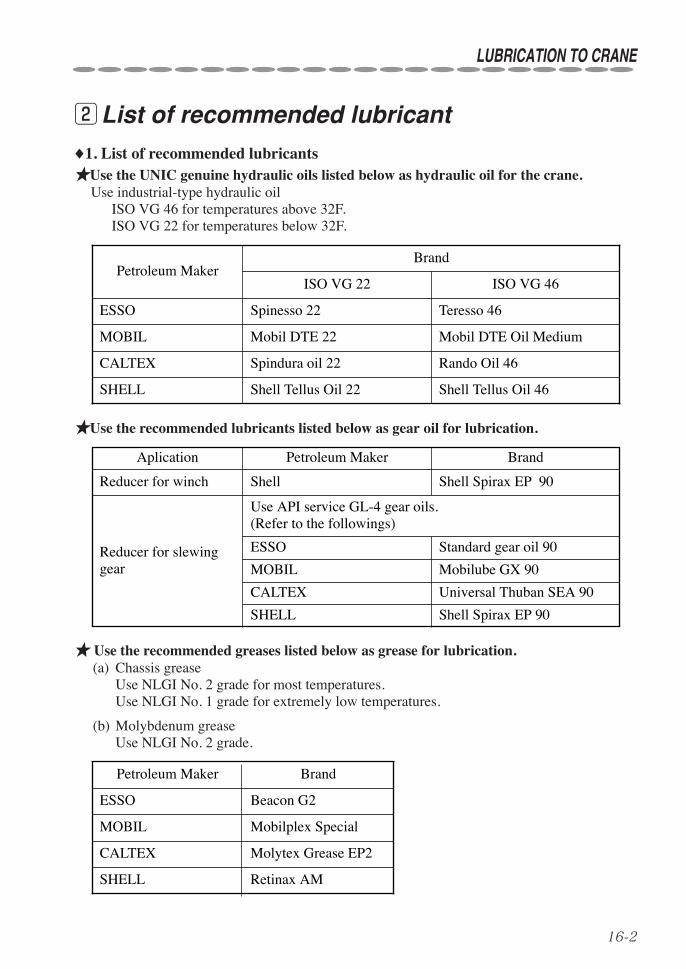
16-2
LUBRICATION TO CRANE
wList of recommended lubricant
♦1. List of recommended lubricants★Use the UNIC genuine hydraulic oils listed below as hydraulic oil for the crane.
Use industrial-type hydraulic oilISO VG 46 for temperatures above 32F.ISO VG 22 for temperatures below 32F.
★Use the recommended lubricants listed below as gear oil for lubrication.
★ Use the recommended greases listed below as grease for lubrication.(a) Chassis grease
Use NLGI No. 2 grade for most temperatures.Use NLGI No. 1 grade for extremely low temperatures.
(b) Molybdenum greaseUse NLGI No. 2 grade.
Petroleum Maker Brand
ESSO Beacon G2
MOBIL Mobilplex Special
CALTEX Molytex Grease EP2
SHELL Retinax AM
Petroleum MakerBrand
ESSO Spinesso 22
MOBIL Mobil DTE 22
CALTEX Spindura oil 22
SHELL Shell Tellus Oil 22 Shell Tellus Oil 46
Rando Oil 46
Mobil DTE Oil Medium
Teresso 46
ISO VG 22 ISO VG 46
Aplication Petroleum Maker Brand
Reducer for winch
Reducer for slewinggear
Shell Shell Spirax EP 90
Use API service GL-4 gear oils.(Refer to the followings)
ESSO
MOBIL
CALTEX
SHELL
Standard gear oil 90
Mobilube GX 90
Universal Thuban SEA 90
Shell Spirax EP 90
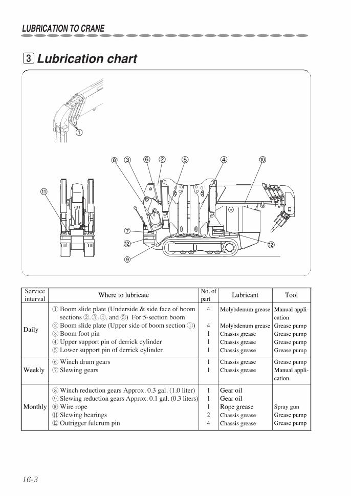
16-3
LUBRICATION TO CRANE
Serviceinterval
Where to lubricateNo. ofpart
Lubricant
Daily
① Boom slide plate (Underside & side face of boomsections ②, ③. ④, and ⑤) For 5-section boom
② Boom slide plate (Upper side of boom section ①)③ Boom foot pin④ Upper support pin of derrick cylinder⑤ Lower support pin of derrick cylinder
4
4111
Molybdenum grease
Molybdenum greaseChassis greaseChassis greaseChassis grease
Weekly⑥Winch drum gears⑦ Slewing gears
11
Chassis greaseChassis grease
Monthly
⑧Winch reduction gears Approx. 0.3 gal. (1.0 liter)⑨ Slewing reduction gears Approx. 0.1 gal. (0.3 liters)⑩Wire rope⑪ Slewing bearings⑫ Outrigger fulcrum pin
11124
Gear oilGear oilRope greaseChassis greaseChassis grease
Spray gunGrease pumpGrease pump
Grease pumpManual appli-cation
Manual appli-cationGrease pumpGrease pumpGrease pumpGrease pump
Tool
eLubrication chart
①
②③ ④⑤⑥
⑪
⑩
⑫ ⑫
⑧
⑨
⑦

16-4
LUBRICATION TO CRANE
rLubrication♦1. Replacement of gear oil(Winch reduction gears and Slewingreduction gears)★Air enters in and out of the gear case sothat dirt and moisture are brought in thegear case.In addition, since hydraulic equipmentgradually wears to produce worn particles,replace gear oil after 6 months from thestart of operation.
★Afterward, replace gear oil:• Once a year for winch reduction gears,
and• Once every 2 years for slewing reduc-
tion gears.
★Replace gear oil after oil tem-perature has dropped.
Winch reduction gears
Slewing reduction gears
CAUTION
★Fill up the oil for winch reduction gearsuntil oil level comes to halfway betweenupper limit and lower limit on the oil levelgauge (oil quantity: approx. 0.3 gal. (1.0 liter).★Fill up the oil for slewing reduction gearuntil oil level comes to halfway betweenupper limit and lower limit on the oil levelgauge (oil quantity: approx. 0.1 gal (0.3liters).In order to check oil level, insert the levelgauge until it just touches the oil level port(not screwing it in).
Gear oil filling port
(Draining oil)
Drain plug
(Filling oil)
Oil level gauge
Gear oil filling port
(Draining oil)
Drain plug
Upper limit
Lower limitOil surface
Oil level gauge
(Filling oil)
Since the drain port is located at lower part of the flame, raise the crane body to drain oil.
In order to facilitate the work, it is recommended that the radio control receiver be removed.

16-5
♦2. Lubrication to slewing bearingsThe crane employs ball bearings as the slew-ing bearing.Be sure to lubricate the bearings as insuffi-cient lubrication may cause it to make unusu-al noise.Grease the nipples while slewing the boomonce a month for moderate operation, andonce a week for heavy-duty operation.
LUBRICATION TO CRANE
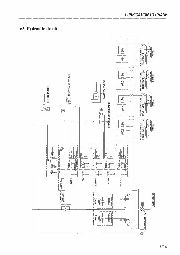
16-6
♦3. Hydraulic circuit
LUBRICATION TO CRANE
aaaabb
RETU
RN F
ILTE
R
SUCT
ION
FILT
ER
ENG
OUTR
IGGE
R
DERR
ICK
HOIS
T
TELE
SCOP
E
SLEW
ING
CYLI
NDER
HYDR
AULI
C M
OTO
R(HO
IST)
DERR
ICK
CYLI
NDER
TELE
SCO
PE C
YLIN
DER
HYDR
AULI
C M
OTO
R(SL
EWIN
G)
MES
H FI
LTER
(PIP
ING
)M
ESH
FILT
ER(P
IPIN
G)
MES
H FI
LTER
(PIP
ING
)
OUTR
IGGE
R CY
LIND
ER(F
RONT・
RIGH
T)OU
TRIG
GER
CYLI
NDER
(FRO
NT・
LEFT
)OU
TRIG
GER
CYLI
NDER
MES
H FI
LTER
(PIP
ING
)
OUTR
IGGE
R CY
LIND
ER(P
EAR・
RIGH
T)(P
EAR・
RIGH
T)
ACCE
LERA
TOR
TRAV
ELIN
G M
OTO
R(R
IGHT
)TR
AVEL
ING
MO
TOR
RE
DR
ED
(LEF
T)
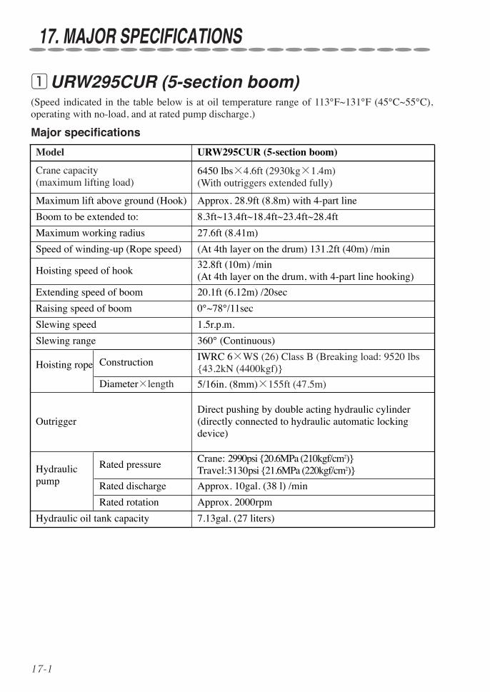
17-1
(Speed indicated in the table below is at oil temperature range of 113°F~131°F (45°C~55°C),operating with no-load, and at rated pump discharge.)
qURW295CUR (5-section boom)
17. MAJOR SPECIFICATIONS
Major specifications
Model URW295CUR (5-section boom)
Crane capacity (maximum lifting load)
Hydraulicpump
6450 lbs×4.6ft (2930kg×1.4m)(With outriggers extended fully)
Maximum lift above ground (Hook) Approx. 28.9ft (8.8m) with 4-part line
Boom to be extended to: 8.3ft~13.4ft~18.4ft~23.4ft~28.4ft
Maximum working radius 27.6ft (8.41m)
Hoisting speed of hook32.8ft (10m) /min(At 4th layer on the drum, with 4-part line hooking)
Extending speed of boom 20.1ft (6.12m) /20sec
Raising speed of boom 0°~78°/11sec
Slewing speed
Speed of winding-up (Rope speed)
1.5r.p.m.
Slewing range
(At 4th layer on the drum) 131.2ft (40m) /min
360° (Continuous)
Hoisting rope Construction IWRC 6×WS (26) Class B (Breaking load: 9520 lbs{43.2kN (4400kgf)}
Diameter×length 5/16in. (8mm)×155ft (47.5m)
OutriggerDirect pushing by double acting hydraulic cylinder(directly connected to hydraulic automatic lockingdevice)
Rated pressureCrane: 2990psi {20.6MPa (210kgf/cm2)}Travel:3130psi {21.6MPa (220kgf/cm2)}
Rated discharge Approx. 10gal. (38 l) /min
Rated rotation Approx. 2000rpm
Hydraulic oil tank capacity 7.13gal. (27 liters)
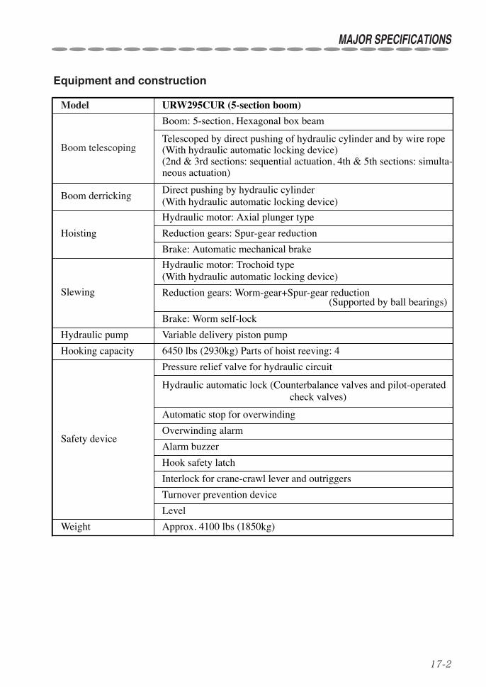
17-2
MAJOR SPECIFICATIONS
Equipment and construction
Model URW295CUR (5-section boom)
Boom telescoping
Boom: 5-section, Hexagonal box beam
Reduction gears: Spur-gear reduction
Telescoped by direct pushing of hydraulic cylinder and by wire rope(With hydraulic automatic locking device)(2nd & 3rd sections: sequential actuation, 4th & 5th sections: simulta-neous actuation)
Boom derrickingDirect pushing by hydraulic cylinder(With hydraulic automatic locking device)
Hoisting
Hydraulic motor: Axial plunger type
Brake: Worm self-lock
Brake: Automatic mechanical brake
Slewing
Hydraulic motor: Trochoid type(With hydraulic automatic locking device)
Reduction gears: Worm-gear+Spur-gear reduction(Supported by ball bearings)
Hydraulic pump Variable delivery piston pump
Safety device
Pressure relief valve for hydraulic circuit
Hydraulic automatic lock (Counterbalance valves and pilot-operatedcheck valves)
Automatic stop for overwinding
Alarm buzzer
Hook safety latch
Interlock for crane-crawl lever and outriggers
Level
Hooking capacity 6450 lbs (2930kg) Parts of hoist reeving: 4
Weight Approx. 4100 lbs (1850kg)
Overwinding alarm
Turnover prevention device
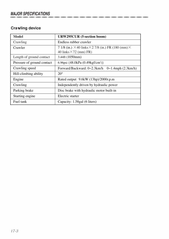
17-3
MAJOR SPECIFICATIONS
Crawling device
Model URW295CUR (5-section boom)
Crawling Endless rubber crawler
6.96psi {48.0kPa (0.49kgf/cm2)}
Crawler 7 1/8 (in.) ×40 links×2 7/8 (in.) FR (180 (mm)×40 links×72 (mm) FR)
Length of ground contact 3.44ft (1050mm)
Rated output 9.6kW (13hp)/2000r.p.m
Forward/Backward: 0~2.3km/h 0~1.4mph (2.3km/h)
Crawling Independently driven by hydraulic power
20°
Parking brake Disc brake with hydraulic motor built-in
Fuel tank Capacity: 1.58gal (6 liters)
Starting engine Electric starter
Crawling speed
Pressure of ground contact
Engine
Hill-climbing ability

17-4
RATED LOADS RATED LOADS
(lbs)
(lbs)
(lbs)
(lbs)
09HQ86040-W295CUR
BOOM SECTION
BOOM SECTION
BOOM SECTION
BOOM SECTION
130180220300380420530600700850350440500590700750920105012801280
25.023.021.019.018.016.015.0
200660
280850
3701000
4501100
5101200
6001350
7501750
8001950
10001950
11.010.08.07.06.05.04.53.0
7.0 8.0 9.5 10.0 11.0 14.0 15.0
11.0 13.0 15.0 16.0 17.0 18.0 20.0
properly.firm and level ground. Make sure lock pins are inserted
If even one outriggers are not fully extended, operatefigures of "not max ext. outriggers"position. Other than the above, operate according topin of each outrigger arm is inserted into the nomalextended to the max. extended position and a swing jack"Max extended outriggers" means inner boxes are
WORKING RADIUS(ft)
WORKING RADIUS(ft)
WORKING RADIUS(ft)
WORKING RADIUS(ft)
NOT MAX EXT.OUTRIGGERS
LOADRATED
OUTRIGGERSMAX EXT.
NOT MAX EXT.OUTRIGGERS
LOADRATED
OUTRIGGERSMAX EXT.
NOT MAX EXT.OUTRIGGERS
LOADRATED
OUTRIGGERSMAX EXT.
17.62
22.61
12.58
13.512.5
12.5
30055060085010001150125015501850100014501650215024502750305030503050
60095011001600225031504450445020002450285038004350495058506450
44506450
1+2+3+4+5
1+2+3+4
1+2+3
1+21
NOT MAX EXT.OUTRIGGERS
LOADRATED
OUTRIGGERSMAX EXT.
CAUTION
and stability of crane.condition. The rated loads are also based on strengthradiuses including the deflection of boom under loadlevel ground and are based on the actual working
4
4
away from boom even a bit. when mark in the side of boom moves1+2+3+4+5
boom is extended even a bit. Do according to1+2+3+4
4
Operate according to the figures of when boom 31+2+3is extended even a bit. Do according to when
Boom means boom is extended up to mark.1+2+3+4
3
the crane. Extend outriggers fully and Place them onImproper set-up of outriggers may cause a turnover ofaccording to the figures of " not max. ext. outriggers".
The rated loads show the performance of the crane on
12.0
27.59
MAJOR SPECIFICATIONS
Chart of rated load

17-5
MAJOR SPECIFICATIONS
Boom :
All boom sections are retracted.
1
Boom : or
Boom section(2) only is extended.
21+2
●How boom-sections are extended
Boom : or
Boom section(4) is extended to the mark .
41+2+3+4
Boom : or
Boom-sections(2), (3), (4), and (5) are fullyextended.
51+2+3+4+5
Boom : or
Boom sections(2) and (3) are extended.
31+2+3
Boom¡
Boom£Boom™
Boom¢
Boom∞
Boom¡ Boom™
Boom¡ Boom£Boom™
Boom¡ Boom£Boom™
Boom¢
Boom∞
Boom¡ Boom£Boom™ Boom¢
Boom∞

17-6
MAJOR SPECIFICATIONS (Radio remote control device)
Model RC-500HA-USA, Radio remote control deviceRadio frequency 458~459 MHz bandTransmission output 10 mWFrequency selection Auto-scanning system
Range of radio wave 100m min. (when in good conditions)System structure Combined system of manual and radio remote control
operationControls (functions operated through radio control transmitter)
Selector switches:Boom :Up/DownHook :Up/DownBoom telescoping :Extend/RetractSlewing :C.C.W./C.W. (Start/Stop)Store hook :StorageSpeed selector switch:Switching to mode of : High/Medium/Low speedMode switch :Switching each function by combina-
tion of selector switchHorn switch :Alarm/StartSpeed lever :Both hydraulic control and engine
speed controlPower supply Crane: Crawler battery (DC 12V)
Transmitter: a size AAA battery: 4 piecesPower consumption Crane operating single function at maximum speed:
Approx. 50W, 120W max. (including control box)Transmitter (service life with alkaline batteries):20 hours min.
Voice messages “Crane mode”“Remote control ready”“Outrigger mode, outriggers moving”“Stop winch up”“Secure lifting hook”“Low transmitter battery”“Service remote control”“Change control mode”
Operating temperature range -4°F~+140°F (-20°C~+60°C)Storing temperature range -22°F~+167°F(-30°C~+75°C)Weight of remote controller 1.5 lbs (700g) (including batteries)
★ The radio remote control device employs a unique data transmission system and an ID (iden-tification) code is assigned to each equipment.Therefore, the crane will not be worked by radio wave radiated from other radio equipment.★ About auto-scanning system :Auto-scanning system is a system that changes the current frequency to other frequencies auto-matically to avoid radio interference when a similar radio wave is being radiated nearby.

18-1
The “mode indicator lamp” is mounted in the control box indicating conditions of crane opera-tion and troubles in detail.
When the “mode indicator lamp” lights, thecrane system is working normally.
When the ”mode indicator lamp” blinks, thecrane system is in a trouble or prohibitedoperation is being carried out.
Mode indicator lamp
◆1. Mode indication when crane is in normal operationIt indicates each operation mode and condition of the crane when it is normal.Description of mode indication when it is in normal is as follows:
Mode indication when crane is in normal condition (lighting indication)
Mode Mode description
Radiocontrol
operationmode
Manualoperation
modePriority
Current control is on normal crane operation mode.Operation is possible either by manual control or byradio remote control.
◯ × 9
Current control is on normal crane operation mode.Operation can only be carried out manually but notthrough radio remote control device.
× ◯ 9
Current control is on traveling mode.No operation other than traveling is possible either bymanual control or by radio remote control.
× × 1
Current control is on low temperature operation mode.Operation can be carried either by manual control orby radio remote control device.
(◯) (◯) 8
Current operation is in outrigger radio control mode.Extension and retraction of outriggers can only be pos-sible by manual control when in manual control modeor by radio remote control when in radio remote con-trol mode.Operation other than the above is impossible either bymanual or by radio remote control.
◯ ×
5
× ◯
18. MODE INDICATOR LAMP (Control box)

18-2
MODE INDICATOR LAMP (Control Box)
Mode Mode description
Radiocontrol
operationmode
Manualoperation
modePriority
Current control is on low temperature operation mode.Operation can be carried by manual control but notthrough radio remote control.
× ◯ 8
Hook hits against weight for over-winding alarm(over-wound condition). ― ― 7
During operation of storing hook. ― ― 6
Automatic stop for over-winding reset switch is beingcontrolled ― ― 4
Outriggers fail to touch the ground or overturn thresh-old alarm is actuated (URW series only). ― ― 2
Outriggers fail to be set up on the ground securely oroverturn prediction alarm is actuated (URW seriesonly).
― ― 3
●RemarksSince priority is assigned for each mode description, it is to be indicated in the order of higherpriority.
If the [.] (dot) is indicated on the bottom right of “mode indicator lamp”, it means the “radiocontrol OFF” mode.Crane cannot be operated through radio control transmitter.
When operated on outrigger radio control mode, crane operation other than extension/retractionof outriggers cannot be carried out.
When the shock-less function has been cancelled, the letter on the left indicated in the modeindicator changes to [ ].Refer to page 12-23 for detail.

18-3
◆2. Mode indication when crane is in troubleWhen the “mode indicator lamp” is blinking figures larger than [ ] (or [ ] lights), thecrane system is in trouble (system trouble indication).If the system trouble indication is found on the “mode indicator lamp”, confirm and follow themode description on the table illustrated below:If the crane becomes impossible to be operated, store the crane by following proceduresdescribed in section 12. i “◆5. Operation in an emergency” (on page 12-40), and ask anauthorized UNIC service shop for repair.
Mode description when crane is in trouble (Blinking indication)
Mode Mode description
Radiocontrol
operationmode
Manualoperation
mode
~No operation is possible either by radio control or by man-ual control. × ×
“Emergency stop switch” has been depressed.If this is indicated even when the “emergency stop switch”has not been depressed, ask a UNIC service shop forrepair.
~
Turn OFF power once then turn it ON.If the trouble persists, ask an authorized UNIC serviceshop for repair.(Although it can be operated either by radio control or bymanually, shock-less function returns to be “active”.)
◯ ◯
×
~ No radio control operation is possible. × ◯
×
Radio control receiver is not connected.Check that cable connector (located inside switch box) ofreceiver is securely connected.Check cable to receiver for damage and break.
× ◯
Either “mode selector switch”, “hook storing switch” or”radio control selector switch” in the control box is faulty.(Failed switch cannot be controlled but crane operation ispossible.)
◯ ◯
Radio control operation cannot be possible and enginespeed control and safety devices will not function.
No operation is possible either by radio control or by man-ual control. × ×
×
No operation is possible either by radio control or by man-ual control.Turn OFF power once then turn it ON again.
× ×
◯
MODE INDICATOR LAMP (Control Box)
(Lights)

18-4
MODE INDICATOR LAMP (Control Box)
Mode Mode description
Radiocontrol
operationmode
Manualoperation
mode
~
~
Stop radio control operation to try controlling levers man-ually.Check that the manual control levers make a smoothmovement and that any of levers will not interfere withanything. If indication fails to return to be normal, ask an authorizedUNIC service shop for repair.
× ×
Either one of “Outrigger control switches” in switch panelof the crane is in failure.(Failed switch cannot be controlled but crane operation ispossible.)
Engine speed control is not carried out correctly.Crane can be operated but if this appears more frequently,ask an authorized UNIC service shop for repair.
◯ ◯
◯
~ No radio control operation is possible. × ◯
◯
~No operation is possible either by radio control or by man-ual control. × ×
~
Batteries of radio control transmitter are running out.Replace old batteries with new ones and turn OFF poweronce then turn it ON again.
◯ ◯
Manual lever is not at its neutral position when power isturned ON.Do not operate the crane as it is carrying out system diag-nosis for about 3 seconds after power has been turned ON.If this appears even when the crane has not been operated,ask an authorized UNIC service shop for repair.
× ×
Capacity of batteries has been dropped.Try actuating reset switch in the control box to reset itonce.If the trouble persists, ask a UNIC authorized serviceshop for repair.Replace old batteries with new ones as capacity ofthem has already been dropped.
× ×

18-5
◆3. Mode indication when crane is mistakenly operatedWhen prohibited operation or combination of operation which may invites dangerous situationshas been carried out, the “mode indicator lamp” will blink corresponding numbers (operationerror indication).When the operation error is indicated, the ”mode indicator lamp” blinks showing correspondingnumbers accordingly.Confirm and follow the mode description concerned on the table illustrated below:
●RemarksThe operation error indication is not to indicate that the crane system is in trouble.The error indication is to be reset when stopping the operation concerned.
Mode description when crane is mistakenly operated (Blinking indication)
Mode Description of wrong operation Measures to be taken
Radio remote control operation iscarried out in manual controlmode.
●Mode indicator lamp located onthe top of cover will not be litwhen in manual control mode.
Radio remote control cannot be carried out inmanual control mode.When operating with radio remote controller,turn the selector switch located on the top ofcover to radio remote control mode.
●Mode indicator lamp located on the top ofcover will be lit when in radio remote controlmode.
Crane is being operated when inoutrigger mode.
Crane cannot be operated when in outriggercontrol mode.When operating crane, turn the mode selectorswitch to “crane” to select crane mode.
Crane and outriggers are operatedsimultaneously.
“Low temperature operationmode” is being switched duringcrane operation.
When crane and outriggers are operated simul-taneously, both operating functions are stoppedautomatically to avoid a risk.Stop the simultaneous operation once and carryout either one of operation.
In order to avoid a risk, “low temperature opera-tion mode” cannot be switched during craneoperation.Stop crane operation once to switch it to “lowtemperature operation mode”.For switching “low temperature operationmode”, refer to section 12 y. “How to correctwhen engine speed becomes unstable due tolow temperature” (on page 12-32).
MODE INDICATOR LAMP (Control Box)

Either one of operation such as“boom Up”, ”hook Up”, or”boom Extend” (when operatedon para-hook mode) is beingcarried out while hook has hitagainst weight for over-windingalarm.
Detach hook from weight for over-windingalarm.●When raising boom through radio controldevice with hook hit against the weight forover-winding alarm, boom is to be “Up”while hook is winding “Down” as this opera-tion allows hook to be released. Do not lift up a cargo while this is beingindicated.
18-6
MODE INDICATOR LAMP (Control Box)
Mode Description of wrong operation Measures to be taken
In the boom/outrigger interlockingdevice, outrigger operation isbeing carried out without boombeing stored.
Stop outrigger operation without boom beingstored.Operate outriggers after boom has been stored.
Operation of winding down hookis carried out while the sensordetecting minimum wire rope isbeing activated.
Stop winding down hook and wind it up so thatthe sensor detecting minimum wire rope willnot be activated.
Emergency stop switch on theremote control device is pressed.
Release the Emergency stop switch when oper-ating crane.

19-1
!0Measures to be taken in an emergencyThe “mode indicator lamp” is mounted in the control box indicating conditions of crane opera-tion and troubles in detail.
Trouble Possible cause Measure to be taken
Crane fails to be oper-ated by radio remotecontrol device.
Batteries in transmitterhave been run out orthey are not loaded.
Replace batteries in transmitter.
Crane works just whena selector switch ontransmitter is actuated.
Speed lever of radiocontrol transmitter isfaulty.
Repair radio control transmitter at aUNIC authorized service shop.
Crane works arbitrari-ly even when no con-trols have been madeor a manual controllever has been shifted.
A solenoid valve ofcontrol valve is in fail-ure.
Depress EMERGENCY stop switch tostop crane operation immediately.Tighten the emergency screw clockwiselightly to its extreme.(Pay attention that the screw may break ifit is tightened with an excessive force.)Depress EMERGENCY stop switch againto reset emergency stop.Check that crane does not work when nocontrols have been made.Store crane with manual levers and ask aUNIC authorized service shop forreplacement of faulty solenoid valve.
19. MEASURES TO BE TAKEN IN AN EMERGENCY
●RemarksThe emergency screw is fixed with a lockpin.Remove the lock pin before turning the emer-gency screw.
(On the top side of control valve)
Emergency screw
Lock pin

HEAD OFFICE : Furukawa Bldg. 3-14, Nihonbashi Muromachi 2-chome, Chuo-ku Tokyo 103-0022, Japan