Embed Size (px)
Citation preview
BOILER INSPECTION GUIDELINES FOR DRUM LEVELINSTRUMENTATION
Requirements from Section I of the ASME Boiler Code
COURTESY OF
Updated to include the 2011 Code Addendawith Recommendations from Section 7
Effective January, 1 2013
16633 Foltz Parkway • Strongsville, OH USA • Ph: (440) 572-1500 • Fax: (440) 238-8828 • www.clark-reliance.com • [email protected]
BOILER INSPECTION GUIDELINES FOR DRUM LEVELINSTRUMENTATION
Requirements from Section I of the ASME Boiler Code
COURTESY OF
Updated to include the 2011 Code Addendawith Recommendations from Section 7
Effective January, 1 2013
16633 Foltz Parkway • Strongsville, OH USA • Ph: (440) 572-1500 • Fax: (440) 238-8828 • www.clark-reliance.com • [email protected] FOLTZ INDUSTRIAL PARKWAY • STRONGSVILLE, OHIO 44149 U.S.A.
PHONE +1 (440) 572-1500 • FAX +1 (440) [email protected] • www.clark-reliance.com
Designing & Manufacturing Boiler Level Control Systems since 1884,Clark-Reliance has become the most recognized and trusted namein boiler-trim controls and operation. That position has beenaccomplished by the continued commitment to excellence in qualityproduct performance and customer service. These values are corecompetencies at Clark-Reliance.
From introducing the first alarm watercolumn to the new microprocessor basedElectro-Eye-Hye® 2000, Clark-Reliancecontinues to lead the industry in boilercontrol safety, performance, and newproduct development. These innovationsare also available to modernize yourexisting level control systems,and improve reliability.
Introduced conductivity probetechnology to the Boiler Industry in 1959
Industry Leader with Drum Levelinstrumentation specified by majorcontractors, OEM’s and users
Complete line of products to 3000 PSI
Over 100 years of manufacturingexperience
Knowledge, Corporate Stability, Quality Service
Active Members of
leading the industry with the most completeline of innovative products and solutions
Agency Approvals
Clark-Reliance® designs and develops product specifications consistentwith the customer’s use for that product, and ensures that all products
and services conform to their established quality specifications.
For the latest product and application solutions, visit clark-reliance.com CLA-384 (REV. 4/11)
RELIANCE BOILER INSTRUMENTATION Instrumentation and Controls Group
BOILER INSTRUMENTATION
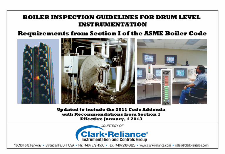
ASME SECTION I WATER GAGE REQUIREMENTS
UNDER 400 PSIGAt Least 1 Direct Reading Gage Glass
In service
400 PSIG and ABOVE2 Direct Reading Gage Glasses
OR1 Direct Reading Gage Glass and
2 Indirect (Remote) Level Indicators
Figure 1
Note: When two Indirect Reading Gages are used to meet Section I requirements, the Direct Reading Gage may bevalved off, but must be maintained in serviceable condition. The 2 Remote Level Indicators must operate independentlyand be continuously displayed.
GAGE VISIBILITY
GOOD PRACTICE IS TO LOCATE ALL ALARMS AND CUTOUTS WITHINWATER GAGE GLASS VISIBILITY
COURTESY OF
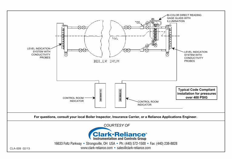
For questions, consult your local Boiler Inspector, Insurance Carrier, or a Reliance Applications Engineer.
CONTROL ROOMINDICATOR CONTROL ROOM
INDICATOR
LEVEL INDICATIONSYSTEM WITHCONDUCTIVITYPROBES
LEVEL INDICATIONSYSTEM WITH
CONDUCTIVITYPROBES
BI-COLOR DIRECT READINGGAGE GLASS WITHILLUMINATION
Typical Code Compliantinstallation for pressures
over 400 PSIG
16633 Foltz Parkway • Strongsville, OH USA • Ph: (440) 572-1500 • Fax: (440) 238-8828 www.clark-reliance.com • [email protected]
WATER COLUMNS
• 1” NPS minimum vessel connections
• ” NPS minimum drain connection
• The steam connection may come out of the topof the vessel (See Connection # 4 on Figure 1)
• The line for the steam connection from thevessel to the water column should be level orslope downward from the drum to the watercolumn (#3)
• The line for the water connection from thevessel to the water column should be level orupward from the vessel to the water column (#2)
• Water columns are defined as “StandardPressure Parts” or Standard Welded Parts” inSubsection PG-11. Therefore, a ManufacturersData report or Code Stamp is not required.
• Water columns are not permitted to beconstructed from austenitic stainless steel
WATER GAGE VALVES• Minimum ” NPS connection to the watercolumn• The Shutoff valves between the drum and thewater column must be OS&Y, of through-flowdesign and orientation.• Install chain operators for operating from thefloor or platform for safe means of operation• Must show position as open or closed.
• Valves must have an unrestricted ” drainopening
GAGE GLASS• Upper visibility to be no higher than loweredge of the steam connection to the drum (#6)• Lower visibility to be no lower than the upperedge of the water connection to the drum (#5)• The lowest visible part of the gage glass (#1)must be at least 2” above the lowestpermissible water level (Level A)• Transparent or tubular glass gage glassesthat relay on observing the steam-waterinterface and have multiple sections, musthave a minimum of 1” overlap of the visibleportions.• Internal lateral structural supports (webs) ina transparent gage glass that obstruct theviewing of the level are prohibited.
• Ported type water gage glasses must befitted with proper illumination to provide visualdiscrimination between water and steam.
Gage Cocks (Try Cocks)• Not required (Since 1991)• If used, must be minimum ” NPS connection.
COURTESY OF
For questions, consult your local Boiler Inspector, Insurance Carrier, or a Reliance Applications Engineer.
CONTROL ROOMINDICATOR CONTROL ROOM
INDICATOR
LEVEL INDICATIONSYSTEM WITHCONDUCTIVITYPROBES
LEVEL INDICATIONSYSTEM WITH
CONDUCTIVITYPROBES
BI-COLOR DIRECT READINGGAGE GLASS WITHILLUMINATION
Typical Code Compliantinstallation for pressures
over 400 PSIG
16633 Foltz Parkway • Strongsville, OH USA • Ph: (440) 572-1500 • Fax: (440) 238-8828 www.clark-reliance.com • [email protected]
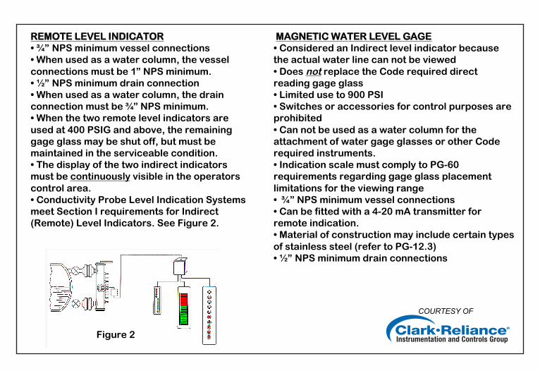
REMOTE LEVEL INDICATOR• ” NPS minimum vessel connections• When used as a water column, the vesselconnections must be 1” NPS minimum.• ” NPS minimum drain connection• When used as a water column, the drainconnection must be ” NPS minimum.• When the two remote level indicators areused at 400 PSIG and above, the remaininggage glass may be shut off, but must bemaintained in the serviceable condition.• The display of the two indirect indicatorsmust be continuously visible in the operatorscontrol area.• Conductivity Probe Level Indication Systemsmeet Section I requirements for Indirect(Remote) Level Indicators. See Figure 2.
MAGNETIC WATER LEVEL GAGE• Considered an Indirect level indicator becausethe actual water line can not be viewed• Does not replace the Code required directreading gage glass• Limited use to 900 PSI• Switches or accessories for control purposes areprohibited• Can not be used as a water column for theattachment of water gage glasses or other Coderequired instruments.• Indication scale must comply to PG-60requirements regarding gage glass placementlimitations for the viewing range• ” NPS minimum vessel connections• Can be fitted with a 4-20 mA transmitter forremote indication.• Material of construction may include certain typesof stainless steel (refer to PG-12.3)• ” NPS minimum drain connections
Figure 2
COURTESY OF
For questions, consult your local Boiler Inspector, Insurance Carrier, or a Reliance Applications Engineer.
CONTROL ROOMINDICATOR CONTROL ROOM
INDICATOR
LEVEL INDICATIONSYSTEM WITHCONDUCTIVITYPROBES
LEVEL INDICATIONSYSTEM WITH
CONDUCTIVITYPROBES
BI-COLOR DIRECT READINGGAGE GLASS WITHILLUMINATION
Typical Code Compliantinstallation for pressures
over 400 PSIG
16633 Foltz Parkway • Strongsville, OH USA • Ph: (440) 572-1500 • Fax: (440) 238-8828 www.clark-reliance.com • [email protected]
COURTESY OF
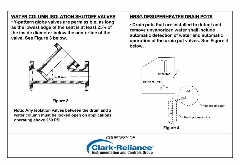
WATER COLUMN ISOLATION SHUTOFF VALVES• Y-pattern globe valves are permissible, as longas the lowest edge of the seat is at least 25% ofthe inside diameter below the centerline of thevalve. See Figure 3 below.
Figure 3
HRSG DESUPERHEATER DRAIN POTS
• Drain pots that are installed to detect andremove unvaporized water shall includeautomatic detection of water and automaticoperation of the drain pot valves. See Figure 4below.
Figure 4
Note: Any isolation valves between the drum and awater column must be locked open on applicationsoperating above 250 PSI
COURTESY OF
COMMON NON-COMPLIANT DRUM LEVEL EQUIPMENTARRANGEMENTS
Magnetic Gages being used as direct reading gages. Magnetic Gages are permitted as a localindirect gage or as a remote level indicator when used with a 4-20mA transmitter to a control areaindicator. A Magnetic Level Gage can not replace the Code required direct reading gage glass.
When the over 400 PSI Code option arrangement is used (two independent indicators for one ofthe gage glasses), the two indirect indicators must be continuously visible in the operators controlarea and the gage valves may be isolated. Viewing the boiler level on a plant operation controlsystem computer screen does not qualify as a continuously visible indicator unless it is always onthe screen. If keystrokes or mouse clicks are required to view the indirect indicator, it does notmeet the Code requirements, as an indirect indicator.
When the over 400 PSI Code Option Arrangement is used, the existing gage glasses must be ableto be brought into service without further action other than opening the isolation valves, closing thedrain valve, and powering on illuminators. Gage glasses that can not be turned on without repairsdo not meet ASME Code requirements.
Bi-color ported type water gages must be fitted with proper illumination to provide visualdiscrimination between water and steam. If not, the gage glass is not in Code compliance.
Not having two independent indirect reading gages when the gage glass image is not directlyvisible in the operators control area or transmitted to the operators control area, by means of acamera, fiber optic system, or mirrors.
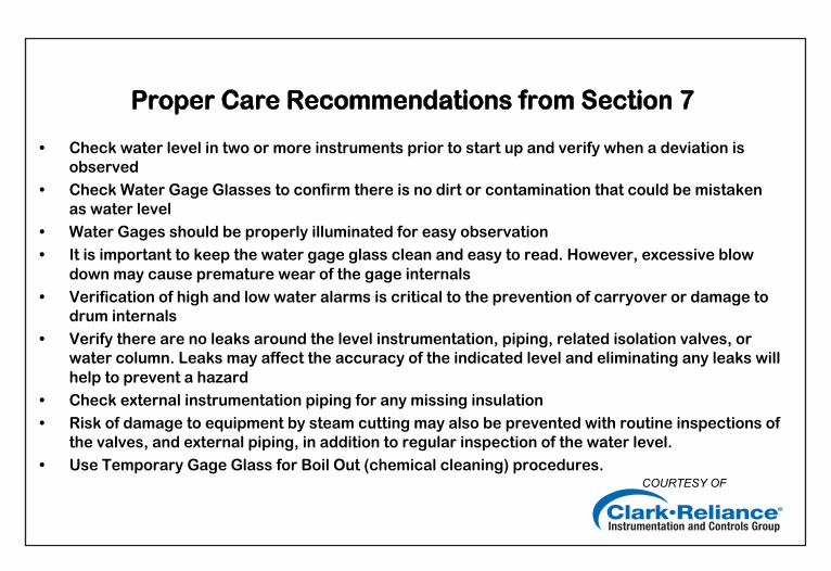
Proper Care Recommendations from Section 7
• Check water level in two or more instruments prior to start up and verify when a deviation isobserved
• Check Water Gage Glasses to confirm there is no dirt or contamination that could be mistaken as water level
• Water Gages should be properly illuminated for easy observation• It is important to keep the water gage glass clean and easy to read. However, excessive blow
down may cause premature wear of the gage internals• Verification of high and low water alarms is critical to the prevention of carryover or damage to
drum internals• Verify there are no leaks around the level instrumentation, piping, related isolation valves, or
water column. Leaks may affect the accuracy of the indicated level and eliminating any leaks willhelp to prevent a hazard
• Check external instrumentation piping for any missing insulation• Risk of damage to equipment by steam cutting may also be prevented with routine inspections of
the valves, and external piping, in addition to regular inspection of the water level.• Use Temporary Gage Glass for Boil Out (chemical cleaning) procedures.
COURTESY OF
For questions, consult your local Boiler Inspector, Insurance Carrier, or a Reliance Applications Engineer.
CONTROL ROOMINDICATOR CONTROL ROOM
INDICATOR
LEVEL INDICATIONSYSTEM WITHCONDUCTIVITYPROBES
LEVEL INDICATIONSYSTEM WITH
CONDUCTIVITYPROBES
BI-COLOR DIRECT READINGGAGE GLASS WITHILLUMINATION
Typical Code Compliantinstallation for pressures
over 400 PSIG
16633 Foltz Parkway • Strongsville, OH USA • Ph: (440) 572-1500 • Fax: (440) 238-8828 www.clark-reliance.com • [email protected]
COURTESY OF
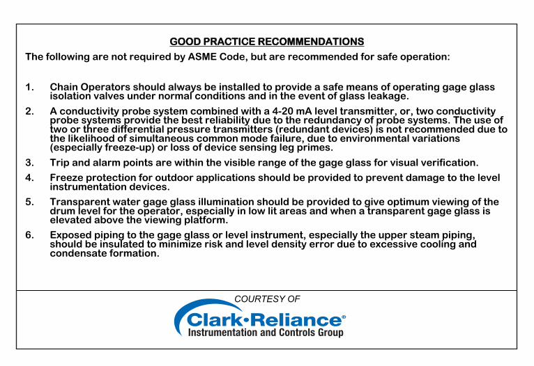
GOOD PRACTICE RECOMMENDATIONS
The following are not required by ASME Code, but are recommended for safe operation:
1. Chain Operators should always be installed to provide a safe means of operating gage glassisolation valves under normal conditions and in the event of glass leakage.
2. A conductivity probe system combined with a 4-20 mA level transmitter, or, two conductivityprobe systems provide the best reliability due to the redundancy of probe systems. The use oftwo or three differential pressure transmitters (redundant devices) is not recommended due tothe likelihood of simultaneous common mode failure, due to environmental variations(especially freeze-up) or loss of device sensing leg primes.
3. Trip and alarm points are within the visible range of the gage glass for visual verification.
4. Freeze protection for outdoor applications should be provided to prevent damage to the levelinstrumentation devices.
5. Transparent water gage glass illumination should be provided to give optimum viewing of thedrum level for the operator, especially in low lit areas and when a transparent gage glass iselevated above the viewing platform.
6. Exposed piping to the gage glass or level instrument, especially the upper steam piping,should be insulated to minimize risk and level density error due to excessive cooling andcondensate formation.
COURTESY OF
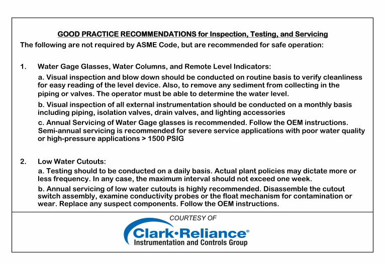
GOOD PRACTICE RECOMMENDATIONS for Inspection, Testing, and Servicing
The following are not required by ASME Code, but are recommended for safe operation:
1. Water Gage Glasses, Water Columns, and Remote Level Indicators:
a. Visual inspection and blow down should be conducted on routine basis to verify cleanlinessfor easy reading of the level device. Also, to remove any sediment from collecting in the piping or valves. The operator must be able to determine the water level.
b. Visual inspection of all external instrumentation should be conducted on a monthly basisincluding piping, isolation valves, drain valves, and lighting accessories
c. Annual Servicing of Water Gage glasses is recommended. Follow the OEM instructions.
Semi-annual servicing is recommended for severe service applications with poor water qualityor high-pressure applications > 1500 PSIG
2. Low Water Cutouts: a. Testing should to be conducted on a daily basis. Actual plant policies may dictate more or
less frequency. In any case, the maximum interval should not exceed one week. b. Annual servicing of low water cutouts is highly recommended. Disassemble the cutout
switch assembly, examine conductivity probes or the float mechanism for contamination orwear. Replace any suspect components. Follow the OEM instructions.
COURTESY OF
For questions, consult your local Boiler Inspector, Insurance Carrier, or a Reliance Applications Engineer.
CONTROL ROOMINDICATOR CONTROL ROOM
INDICATOR
LEVEL INDICATIONSYSTEM WITHCONDUCTIVITYPROBES
LEVEL INDICATIONSYSTEM WITH
CONDUCTIVITYPROBES
BI-COLOR DIRECT READINGGAGE GLASS WITHILLUMINATION
Typical Code Compliantinstallation for pressures
over 400 PSIG
16633 Foltz Parkway • Strongsville, OH USA • Ph: (440) 572-1500 • Fax: (440) 238-8828 www.clark-reliance.com • [email protected] 02/13