Embed Size (px)
Citation preview
University of Karlsruhe
Institute of Telematics
Mobile Communications
Chapter 7: Wireless LANs
Jochen H. Schiller
1999 7.1
Prof. Dr.-Ing. Jochen Schiller, http://www.jochenschiller.de/ MC SS02 7.1
Mobile Communications
Chapter 7: Wireless LANs
Characteristics
IEEE 802.11
PHY
MAC
Roaming
IEEE 802.11a, b, g, e
HIPERLAN
Bluetooth
Comparisons
Prof. Dr.-Ing. Jochen Schiller, http://www.jochenschiller.de/ MC SS02 7.2
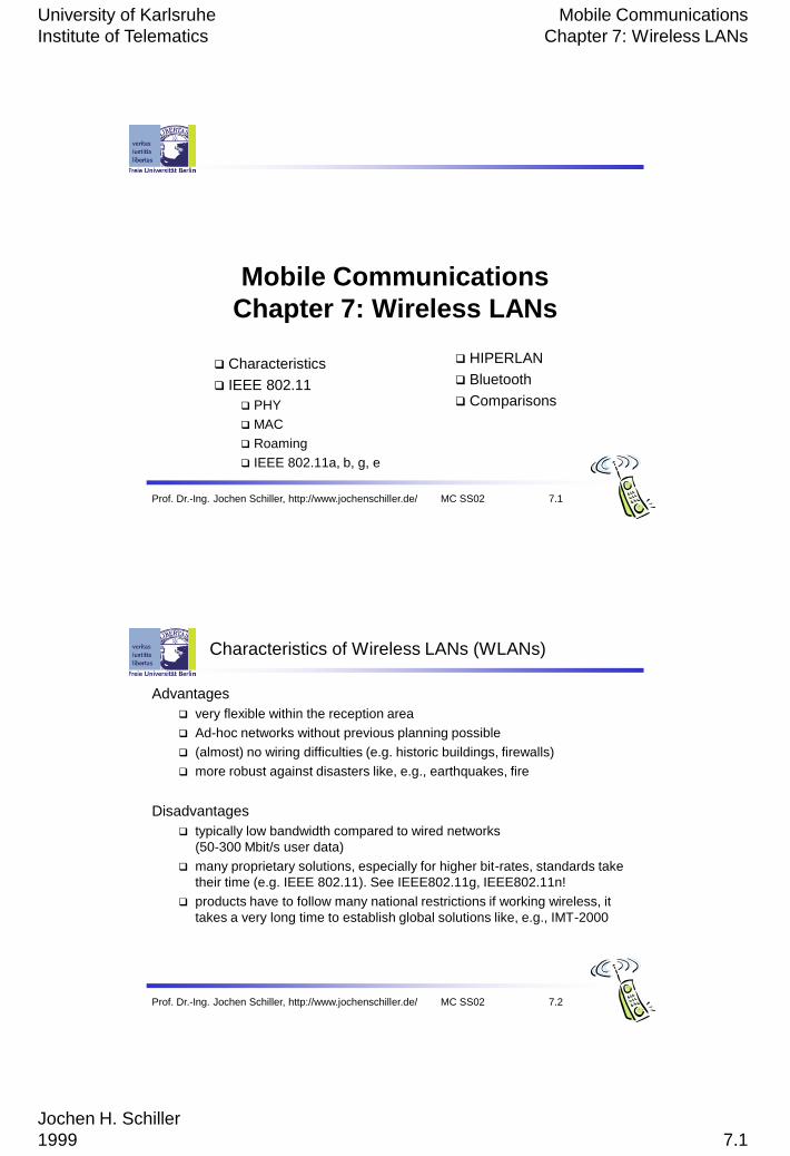
Characteristics of Wireless LANs (WLANs)
Advantages
very flexible within the reception area
Ad-hoc networks without previous planning possible
(almost) no wiring difficulties (e.g. historic buildings, firewalls)
more robust against disasters like, e.g., earthquakes, fire
Disadvantages
typically low bandwidth compared to wired networks
(50-300 Mbit/s user data)
many proprietary solutions, especially for higher bit-rates, standards take
their time (e.g. IEEE 802.11). See IEEE802.11g, IEEE802.11n!
products have to follow many national restrictions if working wireless, it
takes a very long time to establish global solutions like, e.g., IMT-2000
University of Karlsruhe
Institute of Telematics
Mobile Communications
Chapter 7: Wireless LANs
Jochen H. Schiller
1999 7.2
Prof. Dr.-Ing. Jochen Schiller, http://www.jochenschiller.de/ MC SS02 7.3
Design goals for wireless LANs
global, seamless operation
low power for battery use
no special permissions or licenses needed to use the LAN
robust transmission technology – other electrical devices can interfere!
simplified spontaneous cooperation at meetings, i.e. simple set up
easy to use for everyone, simple management
security (no one should be able to read my data), privacy (no one should
be able to collect user profiles), safety (low radiation)
Prof. Dr.-Ing. Jochen Schiller, http://www.jochenschiller.de/ MC SS02 7.4
Comparison: infrared vs. radio transmission
Infrared
uses IR diodes, diffuse light,
multiple reflections (walls,
furniture etc.)
Advantages
simple, cheap, available in
many mobile devices
no licenses needed
simple shielding possible
Disadvantages
interference by sunlight, heat
sources etc.
many things shield or absorb IR
light
low bandwidth
Example
IrDA (Infrared Data Association)
interface available everywhere
Radio
typically using the license free
ISM band at 2.4 GHz
Advantages
experience from wireless WAN
and mobile phones can be used
coverage of larger areas
possible (radio can penetrate
walls, furniture etc.)
Disadvantages
very limited license free
frequency bands
shielding more difficult,
interference with other electrical
devices
Example
IEEE802.11, HIPERLAN,
Bluetooth
University of Karlsruhe
Institute of Telematics
Mobile Communications
Chapter 7: Wireless LANs
Jochen H. Schiller
1999 7.3
Prof. Dr.-Ing. Jochen Schiller, http://www.jochenschiller.de/ MC SS02 7.5
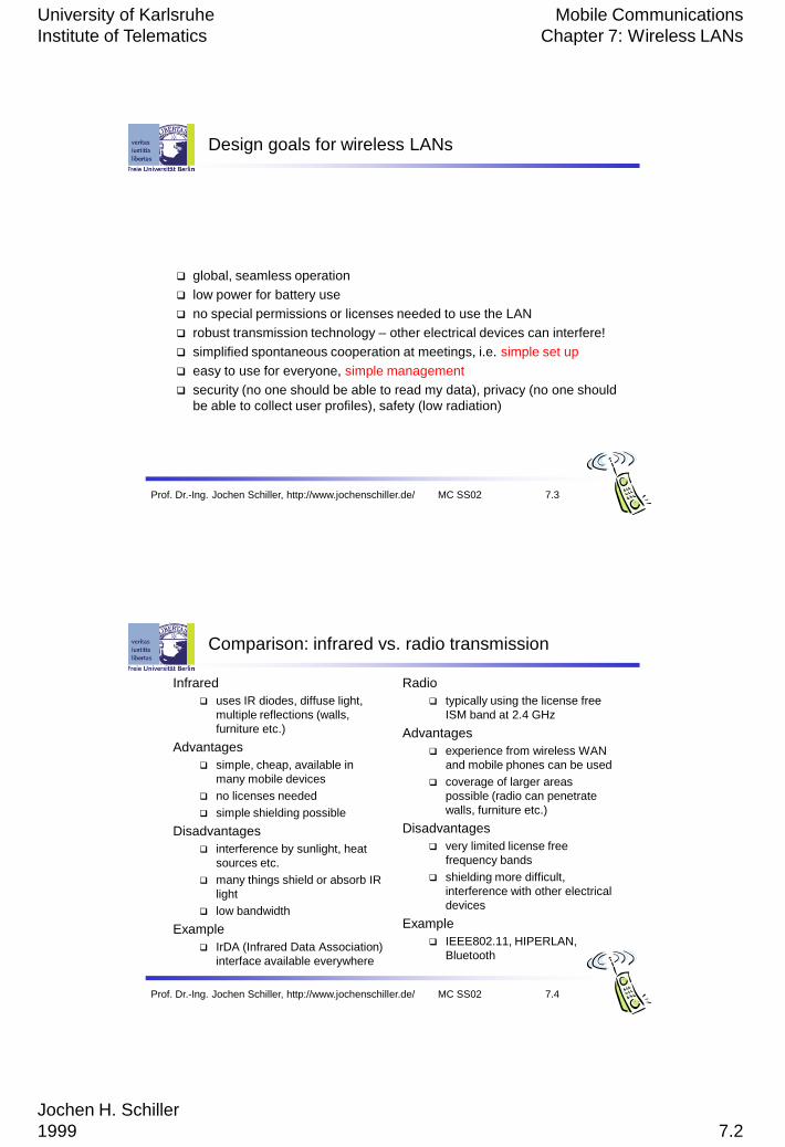
Comparison: infrastructure vs. ad-hoc networks
infrastructure
network
APAP
AP
wired network
AP: Access Point
Infrastructure networks:
• provide access to other networks
• typically communications between the wireless node and the
access point, but not directly between the wireless nodes.
• the access points controls medium access, but also act as a
bridge to other wireless or wired networks
• in the figure three WLANs with different coverage
areas are connected
• most of the network functionality lies within
the access points, whereas the wireless clients
can remain quite simple.
• the MAC can be centralised to the access point
or be distributed oven the wireless clients.
• these wireless networks do rely on the access
points.
Prof. Dr.-Ing. Jochen Schiller, http://www.jochenschiller.de/ MC SS02 7.6
Comparison: infrastructure vs. ad-hoc networks
ad-hoc network
Ad-hoc networks:
• no need for any infrastructure to work.
• each node can communicate directly with other nodes
• no access point controlling media access is necessary
• nodes within an ad-hoc network can communicate
directly or via other nodes
• the complexity of each node is higher because each node has
- implement MAC-mechanisms
- handle hidden or exposed terminal problem
- perhaps priority mechanisms to provide a certain QoS
University of Karlsruhe
Institute of Telematics
Mobile Communications
Chapter 7: Wireless LANs
Jochen H. Schiller
1999 7.4
Prof. Dr.-Ing. Jochen Schiller, http://www.jochenschiller.de/ MC SS02 7.7
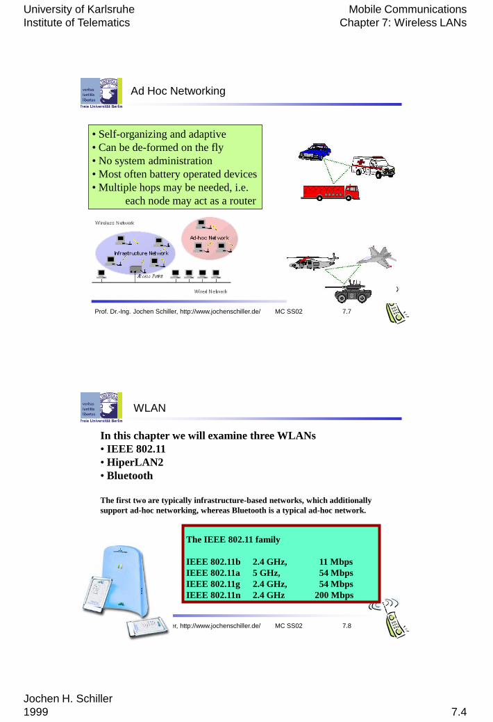
Ad Hoc Networking
• Self-organizing and adaptive
• Can be de-formed on the fly
• No system administration
• Most often battery operated devices
• Multiple hops may be needed, i.e.
each node may act as a router
Prof. Dr.-Ing. Jochen Schiller, http://www.jochenschiller.de/ MC SS02 7.8
WLAN
The IEEE 802.11 family
IEEE 802.11b 2.4 GHz, 11 Mbps
IEEE 802.11a 5 GHz, 54 Mbps
IEEE 802.11g 2.4 GHz, 54 Mbps
IEEE 802.11n 2.4 GHz 200 Mbps
In this chapter we will examine three WLANs
• IEEE 802.11
• HiperLAN2
• Bluetooth
The first two are typically infrastructure-based networks, which additionally
support ad-hoc networking, whereas Bluetooth is a typical ad-hoc network.

University of Karlsruhe
Institute of Telematics
Mobile Communications
Chapter 7: Wireless LANs
Jochen H. Schiller
1999 7.5
Prof. Dr.-Ing. Jochen Schiller, http://www.jochenschiller.de/ MC SS02 7.9
802.11 - Architecture of an infrastructure network
Station (STA)
terminal with access mechanisms to the
wireless medium and radio contact to the
access point
Basic Service Set (BSS)
group of stations using the same radio
frequency
Access Point
station integrated into the wireless LAN and
the distribution system
Portal
bridge to other (wired) networks
Distribution System
interconnection network to form one logical
network (ESS: Extended Service Set) based
on several BSS.
The architecture of the distributing
system is not specified furher in the
IEEE 802.11.
Distribution System
Portal
802.x LAN
Access
Point
802.11 LAN
BSS2
802.11 LAN
BSS1
Access
Point
STA1
STA2 STA3
ESS
Prof. Dr.-Ing. Jochen Schiller, http://www.jochenschiller.de/ MC SS02 7.10
802.11 - Architecture of an infrastructure network
Stations can select an AP and
associate with it.
The APs support roaming, (i.e.
changing access points)
The distribution system handles data
transfer between the different
APs.
APs provide synchronization within a
BSS (Basic Service Set)
APs support power management
APs can control medium access to
support time-bounded services.
Distribution System
Portal
802.x LAN
Access
Point
802.11 LAN
BSS2
802.11 LAN
BSS1
Access
Point
STA1
STA2 STA3
ESS
University of Karlsruhe
Institute of Telematics
Mobile Communications
Chapter 7: Wireless LANs
Jochen H. Schiller
1999 7.6
Prof. Dr.-Ing. Jochen Schiller, http://www.jochenschiller.de/ MC SS02 7.11
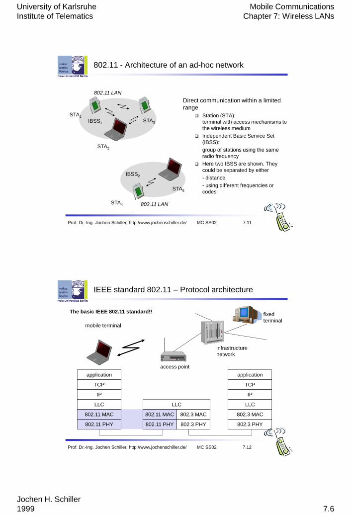
802.11 - Architecture of an ad-hoc network
Direct communication within a limited
range
Station (STA):
terminal with access mechanisms to
the wireless medium
Independent Basic Service Set
(IBSS):
group of stations using the same
radio frequency
Here two IBSS are shown. They
could be separated by either
- distance
- using different frequencies or
codes
802.11 LAN
IBSS2
802.11 LAN
IBSS1
STA1
STA4
STA5
STA2
STA3
Prof. Dr.-Ing. Jochen Schiller, http://www.jochenschiller.de/ MC SS02 7.12
IEEE standard 802.11 – Protocol architecture
mobile terminal
access point
fixed
terminal
application
TCP
802.11 PHY
802.11 MAC
IP
802.3 MAC
802.3 PHY
application
TCP
802.3 PHY
802.3 MAC
IP
802.11 MAC
802.11 PHY
LLC
infrastructure
network
LLC LLC
The basic IEEE 802.11 standard!!
University of Karlsruhe
Institute of Telematics
Mobile Communications
Chapter 7: Wireless LANs
Jochen H. Schiller
1999 7.7
Prof. Dr.-Ing. Jochen Schiller, http://www.jochenschiller.de/ MC SS02 7.13
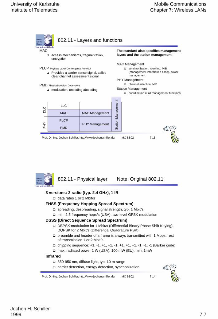
802.11 - Layers and functions
The standard also specifies management
layers and the station management:
MAC Management
synchronization, roaming, MIB
(management information base), power
management
PHY Management
channel selection, MIB
Station Management
coordination of all management functions
MAC
access mechanisms, fragmentation, encryption
PLCP Physical Layer Convergence Protocol
Provides a carrier sense signal, called clear channel assessment signal
PMD Physical Medium Dependent
modulation, encoding /decoding
PMD
PLCP
MAC
LLC
MAC Management
PHY Management
PH
YD
LC
Sta
tio
n M
anagem
ent
Prof. Dr.-Ing. Jochen Schiller, http://www.jochenschiller.de/ MC SS02 7.14
802.11 - Physical layer Note: Original 802.11!
3 versions: 2 radio (typ. 2.4 GHz), 1 IR
data rates 1 or 2 Mbit/s
FHSS (Frequency Hopping Spread Spectrum)
spreading, despreading, signal strength, typ. 1 Mbit/s
min. 2.5 frequency hops/s (USA), two-level GFSK modulation
DSSS (Direct Sequence Spread Spectrum)
DBPSK modulation for 1 Mbit/s (Differential Binary Phase Shift Keying),
DQPSK for 2 Mbit/s (Differential Quadrature PSK)
preamble and header of a frame is always transmitted with 1 Mbps, rest
of transmission 1 or 2 Mbit/s
chipping sequence: +1, -1, +1, +1, -1, +1, +1, +1, -1, -1, -1 (Barker code)
max. radiated power 1 W (USA), 100 mW (EU), min. 1mW
Infrared
850-950 nm, diffuse light, typ. 10 m range
carrier detection, energy detection, synchonization
University of Karlsruhe
Institute of Telematics
Mobile Communications
Chapter 7: Wireless LANs
Jochen H. Schiller
1999 7.8
Prof. Dr.-Ing. Jochen Schiller, http://www.jochenschiller.de/ MC SS02 7.15
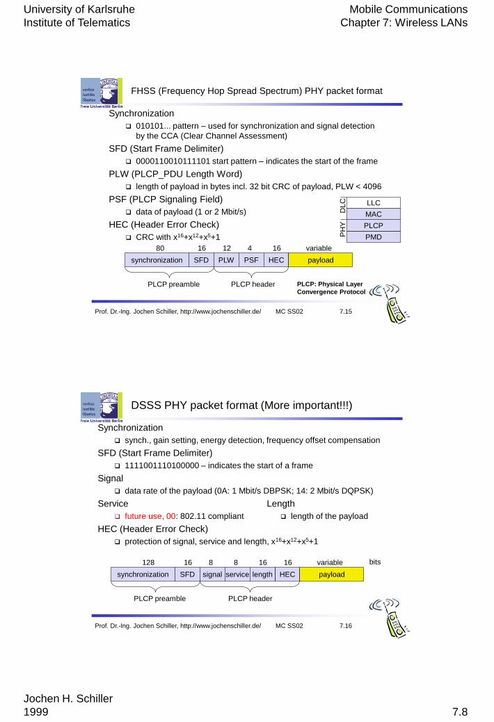
FHSS (Frequency Hop Spread Spectrum) PHY packet format
synchronization SFD PLW PSF HEC payload
PLCP preamble PLCP header
80 16 12 4 16 variable
Synchronization
010101... pattern – used for synchronization and signal detection
by the CCA (Clear Channel Assessment)
SFD (Start Frame Delimiter)
0000110010111101 start pattern – indicates the start of the frame
PLW (PLCP_PDU Length Word)
length of payload in bytes incl. 32 bit CRC of payload, PLW < 4096
PSF (PLCP Signaling Field)
data of payload (1 or 2 Mbit/s)
HEC (Header Error Check)
CRC with x16+x12+x5+1
PLCP: Physical Layer
Convergence Protocol
PMD
PLCP
MAC
LLC
PH
YD
LC
Prof. Dr.-Ing. Jochen Schiller, http://www.jochenschiller.de/ MC SS02 7.16
DSSS PHY packet format (More important!!!)
synchronization SFD signal service HEC payload
PLCP preamble PLCP header
128 16 8 8 16 variable bits
length
16
Synchronization
synch., gain setting, energy detection, frequency offset compensation
SFD (Start Frame Delimiter)
1111001110100000 – indicates the start of a frame
Signal
data rate of the payload (0A: 1 Mbit/s DBPSK; 14: 2 Mbit/s DQPSK)
Service Length
future use, 00: 802.11 compliant length of the payload
HEC (Header Error Check)
protection of signal, service and length, x16+x12+x5+1
University of Karlsruhe
Institute of Telematics
Mobile Communications
Chapter 7: Wireless LANs
Jochen H. Schiller
1999 7.9
Prof. Dr.-Ing. Jochen Schiller, http://www.jochenschiller.de/ MC SS02 7.17
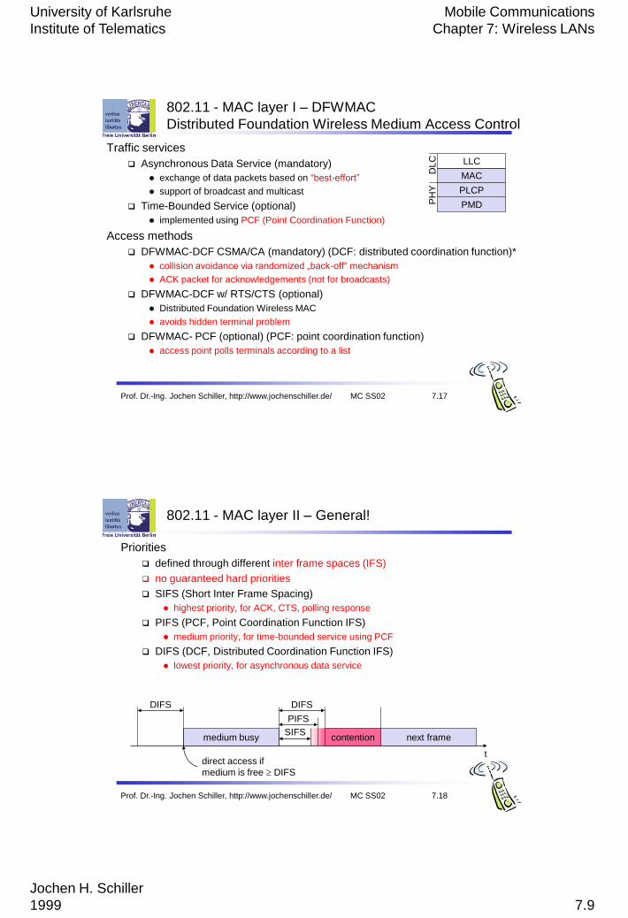
802.11 - MAC layer I – DFWMAC
Distributed Foundation Wireless Medium Access Control
Traffic services
Asynchronous Data Service (mandatory)
exchange of data packets based on “best-effort”
support of broadcast and multicast
Time-Bounded Service (optional)
implemented using PCF (Point Coordination Function)
Access methods
DFWMAC-DCF CSMA/CA (mandatory) (DCF: distributed coordination function)*
collision avoidance via randomized „back-off“ mechanism
ACK packet for acknowledgements (not for broadcasts)
DFWMAC-DCF w/ RTS/CTS (optional)
Distributed Foundation Wireless MAC
avoids hidden terminal problem
DFWMAC- PCF (optional) (PCF: point coordination function)
access point polls terminals according to a list
PMD
PLCP
MAC
LLC
PH
YD
LC
Prof. Dr.-Ing. Jochen Schiller, http://www.jochenschiller.de/ MC SS02 7.18
802.11 - MAC layer II – General!
Priorities
defined through different inter frame spaces (IFS)
no guaranteed hard priorities
SIFS (Short Inter Frame Spacing)
highest priority, for ACK, CTS, polling response
PIFS (PCF, Point Coordination Function IFS)
medium priority, for time-bounded service using PCF
DIFS (DCF, Distributed Coordination Function IFS)
lowest priority, for asynchronous data service
t
medium busySIFS
PIFS
DIFSDIFS
next framecontention
direct access if
medium is free DIFS
University of Karlsruhe
Institute of Telematics
Mobile Communications
Chapter 7: Wireless LANs
Jochen H. Schiller
1999 7.10
Prof. Dr.-Ing. Jochen Schiller, http://www.jochenschiller.de/ MC SS02 7.19
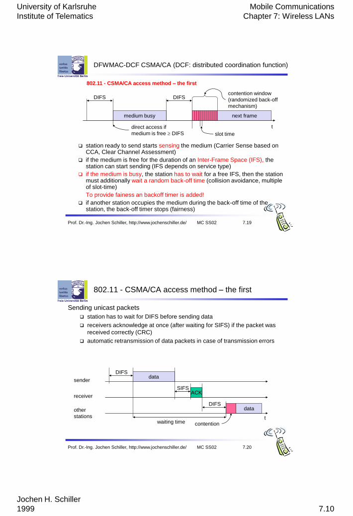
DFWMAC-DCF CSMA/CA (DCF: distributed coordination function)
station ready to send starts sensing the medium (Carrier Sense based on CCA, Clear Channel Assessment)
if the medium is free for the duration of an Inter-Frame Space (IFS), the station can start sending (IFS depends on service type)
if the medium is busy, the station has to wait for a free IFS, then the station must additionally wait a random back-off time (collision avoidance, multiple of slot-time)
To provide fainess an backoff timer is added!
if another station occupies the medium during the back-off time of the station, the back-off timer stops (fairness)
t
medium busy
DIFSDIFS
next frame
contention window
(randomized back-off
mechanism)
slot time
direct access if
medium is free DIFS
802.11 - CSMA/CA access method – the first
Prof. Dr.-Ing. Jochen Schiller, http://www.jochenschiller.de/ MC SS02 7.20
802.11 - CSMA/CA access method – the first
Sending unicast packets
station has to wait for DIFS before sending data
receivers acknowledge at once (after waiting for SIFS) if the packet was
received correctly (CRC)
automatic retransmission of data packets in case of transmission errors
t
SIFS
DIFS
data
ACK
waiting time
other
stations
receiver
senderdata
DIFS
contention

University of Karlsruhe
Institute of Telematics
Mobile Communications
Chapter 7: Wireless LANs
Jochen H. Schiller
1999 7.11
Prof. Dr.-Ing. Jochen Schiller, http://www.jochenschiller.de/ MC SS02 7.21
802.11 - competing stations - simple version
t
busy
boe
station1
station2
station3
station4
station5
packet arrival at MAC
DIFS
boe
boe
boe
busy
elapsed backoff time
borresidual backoff time
busy medium not idle (frame, ack etc.)
bor
bor
DIFS
boe
boe
boe bor
DIFS
busy
busy
DIFS
boe busy
boe
boe
bor
bor
Prof. Dr.-Ing. Jochen Schiller, http://www.jochenschiller.de/ MC SS02 7.22
802.11 – DFWMAC-DCF with RTS/CTS extension
To avoid the hidden terminal problem!!
Sending unicast packets
station can send RTS with reservation parameter after waiting for DIFS (reservation determines amount of time the data packet needs the medium)
acknowledgement via CTS after SIFS by receiver (if ready to receive)
sender can now send data at once, acknowledgement via ACK
other stations store medium reservations distributed via RTS and CTS
t
SIFS
DIFS
data
ACK
defer access
other
stations
receiver
senderdata
DIFS
contention
RTS
CTSSIFS SIFS
NAV (RTS)NAV (CTS)
NAV: Net Allocation Vector
The second!
University of Karlsruhe
Institute of Telematics
Mobile Communications
Chapter 7: Wireless LANs
Jochen H. Schiller
1999 7.12
Prof. Dr.-Ing. Jochen Schiller, http://www.jochenschiller.de/ MC SS02 7.23
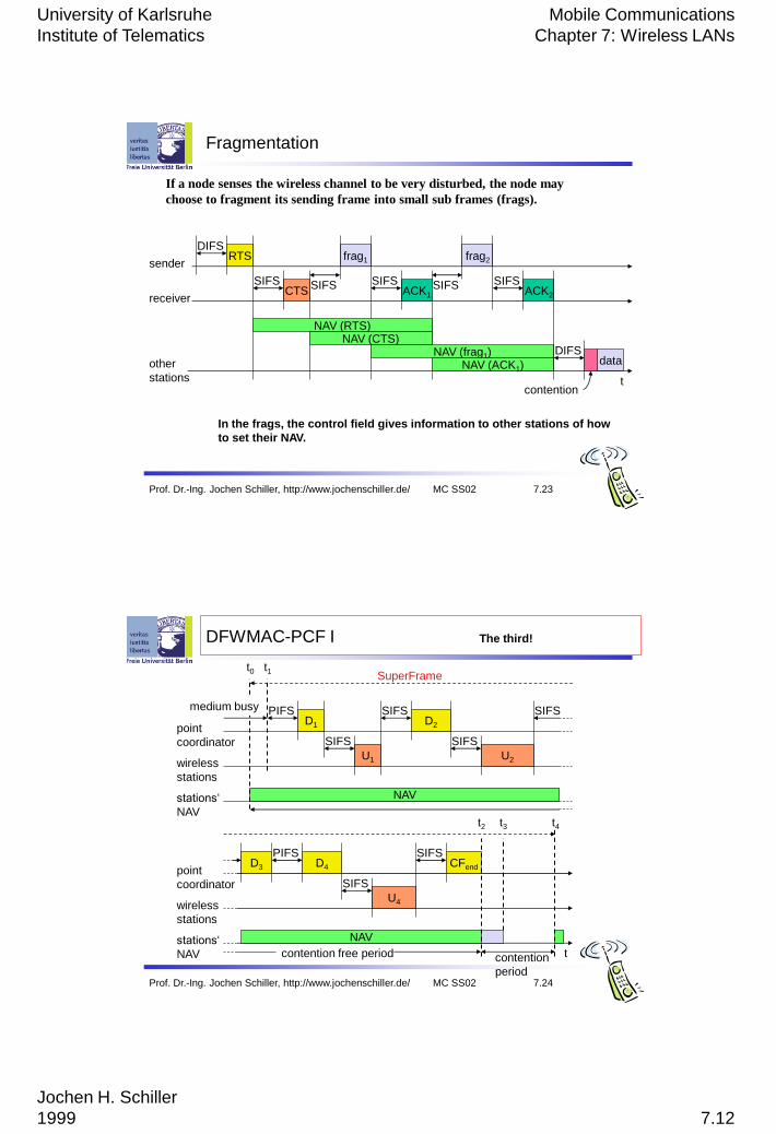
Fragmentation
t
SIFS
DIFS
data
ACK1
other
stations
receiver
senderfrag1
DIFS
contention
RTS
CTSSIFS SIFS
NAV (RTS)NAV (CTS)
NAV (frag1)NAV (ACK1)
SIFSACK2
frag2
SIFS
In the frags, the control field gives information to other stations of how
to set their NAV.
If a node senses the wireless channel to be very disturbed, the node may
choose to fragment its sending frame into small sub frames (frags).
Prof. Dr.-Ing. Jochen Schiller, http://www.jochenschiller.de/ MC SS02 7.24
DFWMAC-PCF I
PIFS
stations„
NAV
wireless
stations
point
coordinator
D1
U1
SIFS
NAV
SIFSD2
U2
SIFS
SIFS
SuperFramet0
medium busy
t1
The third!
tstations„
NAV
wireless
stations
point
coordinator
D3
NAV
PIFSD4
U4
SIFS
SIFSCFend
contention
period
contention free period
t2 t3 t4
University of Karlsruhe
Institute of Telematics
Mobile Communications
Chapter 7: Wireless LANs
Jochen H. Schiller
1999 7.13
Prof. Dr.-Ing. Jochen Schiller, http://www.jochenschiller.de/ MC SS02 7.25
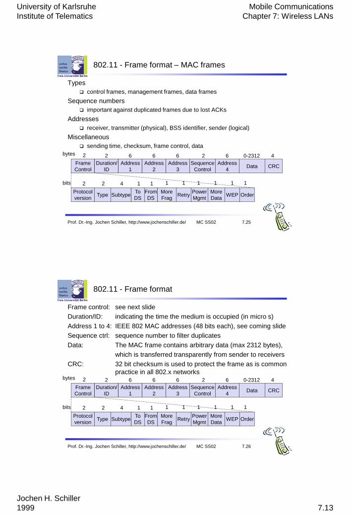
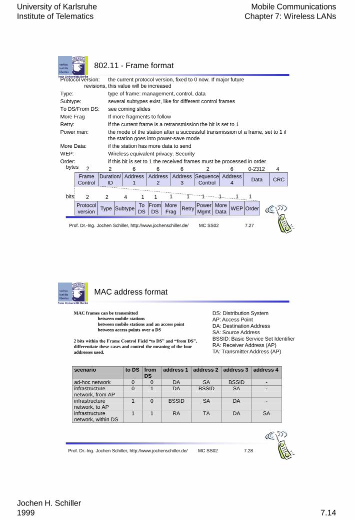
802.11 - Frame format – MAC frames
Types
control frames, management frames, data frames
Sequence numbers
important against duplicated frames due to lost ACKs
Addresses
receiver, transmitter (physical), BSS identifier, sender (logical)
Miscellaneous
sending time, checksum, frame control, data
Frame
Control
Duration/
ID
Address
1
Address
2
Address
3
Sequence
Control
Address
4Data CRC
2 2 6 6 6 62 40-2312bytes
Protocol
versionType Subtype
To
DS
More
FragRetry
Power
Mgmt
More
DataWEP
2 2 4 1
From
DS
1
Order
bits 1 1 1 1 1 1
Prof. Dr.-Ing. Jochen Schiller, http://www.jochenschiller.de/ MC SS02 7.26
802.11 - Frame format
Frame control: see next slide
Duration/ID: indicating the time the medium is occupied (in micro s)
Address 1 to 4: IEEE 802 MAC addresses (48 bits each), see coming slide
Sequence ctrl: sequence number to filter duplicates
Data: The MAC frame contains arbitrary data (max 2312 bytes),
which is transferred transparently from sender to receivers
CRC: 32 bit checksum is used to protect the frame as is common
practice in all 802.x networks
Frame
Control
Duration/
ID
Address
1
Address
2
Address
3
Sequence
Control
Address
4Data CRC
2 2 6 6 6 62 40-2312bytes
Protocol
versionType Subtype
To
DS
More
FragRetry
Power
Mgmt
More
DataWEP
2 2 4 1
From
DS
1
Order
bits 1 1 1 1 1 1
University of Karlsruhe
Institute of Telematics
Mobile Communications
Chapter 7: Wireless LANs
Jochen H. Schiller
1999 7.14
Prof. Dr.-Ing. Jochen Schiller, http://www.jochenschiller.de/ MC SS02 7.27
802.11 - Frame format
Protocol version: the current protocol version, fixed to 0 now. If major future
revisions, this value will be increased
Type: type of frame: management, control, data
Subtype: several subtypes exist, like for different control frames
To DS/From DS: see coming slides
More Frag If more fragments to follow
Retry: if the current frame is a retransmission the bit is set to 1
Power man: the mode of the station after a successful transmission of a frame, set to 1 if
the station goes into power-save mode
More Data: if the station has more data to send
WEP: Wireless equivalent privacy. Security
Order: if this bit is set to 1 the received frames must be processed in order
Frame
Control
Duration/
ID
Address
1
Address
2
Address
3
Sequence
Control
Address
4Data CRC
2 2 6 6 6 62 40-2312bytes
Protocol
versionType Subtype
To
DS
More
FragRetry
Power
Mgmt
More
DataWEP
2 2 4 1
From
DS
1
Order
bits 1 1 1 1 1 1
Prof. Dr.-Ing. Jochen Schiller, http://www.jochenschiller.de/ MC SS02 7.28
MAC address format
scenario to DS fromDS
address 1 address 2 address 3 address 4
ad-hoc network 0 0 DA SA BSSID -
infrastructurenetwork, from AP
0 1 DA BSSID SA -
infrastructurenetwork, to AP
1 0 BSSID SA DA -
infrastructurenetwork, within DS
1 1 RA TA DA SA
DS: Distribution System
AP: Access Point
DA: Destination Address
SA: Source Address
BSSID: Basic Service Set Identifier
RA: Receiver Address (AP)
TA: Transmitter Address (AP)
MAC frames can be transmitted
between mobile stations
between mobile stations and an access point
between access points over a DS
2 bits within the Frame Control Field “to DS” and “from DS”,
differentiate these cases and control the meaning of the four
addresses used.
University of Karlsruhe
Institute of Telematics
Mobile Communications
Chapter 7: Wireless LANs
Jochen H. Schiller
1999 7.15
Prof. Dr.-Ing. Jochen Schiller, http://www.jochenschiller.de/ MC SS02 7.29
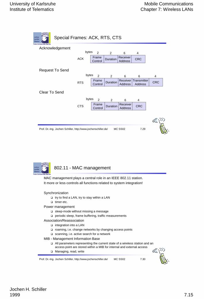
Special Frames: ACK, RTS, CTS
Acknowledgement
Request To Send
Clear To Send
Frame
ControlDuration
Receiver
Address
Transmitter
AddressCRC
2 2 6 6 4bytes
Frame
ControlDuration
Receiver
AddressCRC
2 2 6 4bytes
Frame
ControlDuration
Receiver
AddressCRC
2 2 6 4bytes
ACK
RTS
CTS
Prof. Dr.-Ing. Jochen Schiller, http://www.jochenschiller.de/ MC SS02 7.30
802.11 - MAC management
MAC management plays a central role in an IEEE 802.11 station.
It more or less controls all functions related to system integration!
Synchronization
try to find a LAN, try to stay within a LAN
timer etc.
Power management
sleep-mode without missing a message
periodic sleep, frame buffering, traffic measurements
Association/Reassociation
integration into a LAN
roaming, i.e. change networks by changing access points
scanning, i.e. active search for a network
MIB - Management Information Base
All parameters representing the current state of a wireless station and an
access point are stored within a MIB for internal and external access
Managing, read, write
University of Karlsruhe
Institute of Telematics
Mobile Communications
Chapter 7: Wireless LANs
Jochen H. Schiller
1999 7.16
Prof. Dr.-Ing. Jochen Schiller, http://www.jochenschiller.de/ MC SS02 7.31
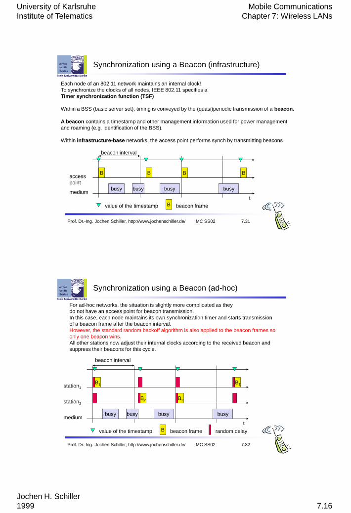
Synchronization using a Beacon (infrastructure)
beacon interval
tmedium
access
pointbusy
B
busy busy busy
B B B
value of the timestamp B beacon frame
Each node of an 802.11 network maintains an internal clock!
To synchronize the clocks of all nodes, IEEE 802.11 specifies a
Timer synchronization function (TSF)
Within a BSS (basic server set), timing is conveyed by the (quasi)periodic transmission of a beacon.
A beacon contains a timestamp and other management information used for power management
and roaming (e.g. identification of the BSS).
Within infrastructure-base networks, the access point performs synch by transmitting beacons
Prof. Dr.-Ing. Jochen Schiller, http://www.jochenschiller.de/ MC SS02 7.32
Synchronization using a Beacon (ad-hoc)
tmedium
station1
busy
B1
beacon interval
busy busy busy
B1
value of the timestamp B beacon frame
station2
B2 B2
random delay
For ad-hoc networks, the situation is slightly more complicated as they
do not have an access point for beacon transmission.
In this case, each node maintains its own synchronization timer and starts transmission
of a beacon frame after the beacon interval.
However, the standard random backoff algorithm is also applied to the beacon frames so
only one beacon wins.
All other stations now adjust their internal clocks according to the received beacon and
suppress their beacons for this cycle.
University of Karlsruhe
Institute of Telematics
Mobile Communications
Chapter 7: Wireless LANs
Jochen H. Schiller
1999 7.17
Prof. Dr.-Ing. Jochen Schiller, http://www.jochenschiller.de/ MC SS02 7.33
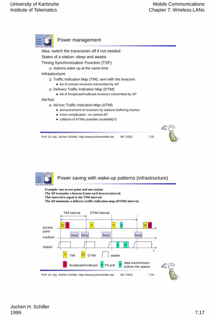
Power management
Idea: switch the transceiver off if not needed
States of a station: sleep and awake
Timing Synchronization Function (TSF)
stations wake up at the same time
Infrastructure
Traffic Indication Map (TIM), sent with the beacons
list of unicast receivers transmitted by AP
Delivery Traffic Indication Map (DTIM)
list of broadcast/multicast receivers transmitted by AP
Ad-hoc
Ad-hoc Traffic Indication Map (ATIM)
announcement of receivers by stations buffering frames
more complicated - no central AP
collision of ATIMs possible (scalability?)
Prof. Dr.-Ing. Jochen Schiller, http://www.jochenschiller.de/ MC SS02 7.34
Power saving with wake-up patterns (infrastructure)
TIM interval
t
medium
access
pointbusy
D
busy busy busy
T T D
T TIM D DTIM
DTIM interval
BB
B broadcast/multicast
station
awake
p PS poll
p
d
d
ddata transmission
to/from the station
Example: one access point and one station
The AP transmits a beacon frame each beacon interval.
This interval is equal to the TIM interval.
The AP maintains a delivery traffic indication map (DTIM) interval.
University of Karlsruhe
Institute of Telematics
Mobile Communications
Chapter 7: Wireless LANs
Jochen H. Schiller
1999 7.18
Prof. Dr.-Ing. Jochen Schiller, http://www.jochenschiller.de/ MC SS02 7.35
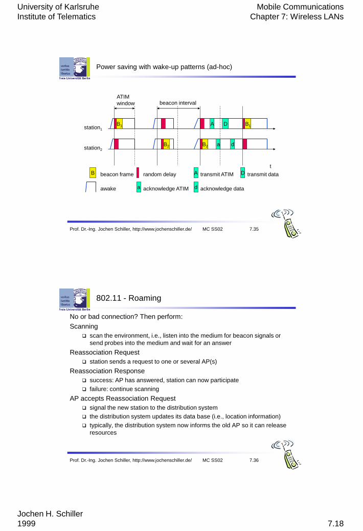
Power saving with wake-up patterns (ad-hoc)
awake
A transmit ATIM D transmit data
t
station1
B1 B1
B beacon frame
station2
B2 B2
random delay
A
a
D
d
ATIM
window beacon interval
a acknowledge ATIM d acknowledge data
Prof. Dr.-Ing. Jochen Schiller, http://www.jochenschiller.de/ MC SS02 7.36
802.11 - Roaming
No or bad connection? Then perform:
Scanning
scan the environment, i.e., listen into the medium for beacon signals or
send probes into the medium and wait for an answer
Reassociation Request
station sends a request to one or several AP(s)
Reassociation Response
success: AP has answered, station can now participate
failure: continue scanning
AP accepts Reassociation Request
signal the new station to the distribution system
the distribution system updates its data base (i.e., location information)
typically, the distribution system now informs the old AP so it can release
resources
University of Karlsruhe
Institute of Telematics
Mobile Communications
Chapter 7: Wireless LANs
Jochen H. Schiller
1999 7.19
IEEE 802.11b (IEEE 1999)
Supplement to the original standard (Higher speed physical layer
extension in the 2.4 GHz band)
A new physical layer (JUST A NEW PHYSICAL LAYER!)
All the MAC schemes, management procedures, etc are still used.
Depending on the current interface and the distance between sender
and reciever 802.11 systems offer 11, 5.5, 2 or 1 Mbps
Next slide shows the mandatory packet format for 802.11b which is
similar to the original. – There are others as well. However all control
packets follow the mandatory for all stations to understand.
Operates on certain frequencies at the 2.4 GHz ISM band.
These frequences depend on national regulations.
Prof. Dr.-Ing. Jochen Schiller, http://www.jochenschiller.de/ MC SS02 7.37
Prof. Dr.-Ing. Jochen Schiller, http://www.jochenschiller.de/ MC SS02 7.38
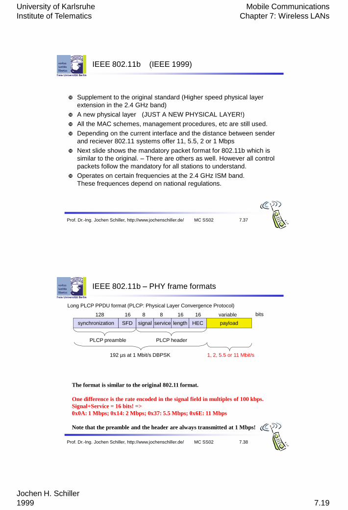
IEEE 802.11b – PHY frame formats
synchronization SFD signal service HEC payload
PLCP preamble PLCP header
128 16 8 8 16 variable bits
length
16
192 µs at 1 Mbit/s DBPSK 1, 2, 5.5 or 11 Mbit/s
Long PLCP PPDU format (PLCP: Physical Layer Convergence Protocol)
The format is similar to the original 802.11 format.
One difference is the rate encoded in the signal field in multiples of 100 kbps.
Signal+Service = 16 bits! =>
0x0A: 1 Mbps; 0x14: 2 Mbps; 0x37: 5.5 Mbps; 0x6E: 11 Mbps
Note that the preamble and the header are always transmitted at 1 Mbps!
University of Karlsruhe
Institute of Telematics
Mobile Communications
Chapter 7: Wireless LANs
Jochen H. Schiller
1999 7.20
Prof. Dr.-Ing. Jochen Schiller, http://www.jochenschiller.de/ MC SS02 7.39
IEEE 802.11b – PHY frame formats
synchronization SFD signal service HEC payload
PLCP preamble PLCP header
128 16 8 8 16 variable bits
length
16
192 µs at 1 Mbit/s DBPSK 1, 2, 5.5 or 11 Mbit/s
short synch. SFD signal service HEC payload
PLCP preamble
(1 Mbit/s, DBPSK)
PLCP header
(2 Mbit/s, DQPSK)
56 16 8 8 16 variable bits
length
16
96 µs 2, 5.5 or 11 Mbit/s
Long PLCP PPDU format (PLCP: Physical Layer Convergence Protocol)
Short PLCP PPDU format (optional)
Channel plan for IEEE 802.11b
Prof. Dr.-Ing. Jochen Schiller, http://www.jochenschiller.de/ MC SS02 7.40
Channel Frequency (MHz) US/Canada Europé Japan
1 2412 x x x
2 2417 x x x
3 2422 x x x
4 2427 x x x
5 2432 x x x
6 2437 x x x
7 2442 x x x
8 2447 x x x
9 2452 x x x
10 2457 x x x
11 2462 x x x
12 2467 - x x
13 2472 - x x
14 2484 - - x
Altogether 14 channels have been defined as the table shows.
For each channel a center frequency is given.
Depending on national restrictions 11 (US/Canada), 13 (Europe) or
14 channels (Japan) can be used.
University of Karlsruhe
Institute of Telematics
Mobile Communications
Chapter 7: Wireless LANs
Jochen H. Schiller
1999 7.21
Prof. Dr.-Ing. Jochen Schiller, http://www.jochenschiller.de/ MC SS02 7.41
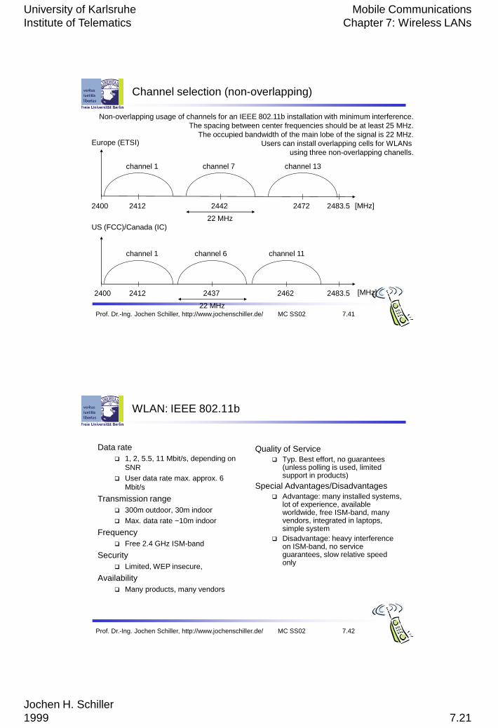
Channel selection (non-overlapping)
2400 [MHz]2412 2483.52442 2472
channel 1 channel 7 channel 13
Europe (ETSI)
US (FCC)/Canada (IC)
2400 [MHz]2412 2483.52437 2462
channel 1 channel 6 channel 11
22 MHz
22 MHz
Non-overlapping usage of channels for an IEEE 802.11b installation with minimum interference.
The spacing between center frequencies should be at least 25 MHz.
The occupied bandwidth of the main lobe of the signal is 22 MHz.
Users can install overlapping cells for WLANs
using three non-overlapping chanells.
Prof. Dr.-Ing. Jochen Schiller, http://www.jochenschiller.de/ MC SS02 7.42
WLAN: IEEE 802.11b
Data rate
1, 2, 5.5, 11 Mbit/s, depending on
SNR
User data rate max. approx. 6
Mbit/s
Transmission range
300m outdoor, 30m indoor
Max. data rate ~10m indoor
Frequency
Free 2.4 GHz ISM-band
Security
Limited, WEP insecure,
Availability
Many products, many vendors
Quality of Service
Typ. Best effort, no guarantees (unless polling is used, limited support in products)
Special Advantages/Disadvantages
Advantage: many installed systems, lot of experience, available worldwide, free ISM-band, many vendors, integrated in laptops, simple system
Disadvantage: heavy interference on ISM-band, no service guarantees, slow relative speed only
University of Karlsruhe
Institute of Telematics
Mobile Communications
Chapter 7: Wireless LANs
Jochen H. Schiller
1999 7.22
IEEE 802.11a
Initially aimed at the US 5 GHz U-NII (Unlicenced National Information
Infrastucture) bands.
Offering up to 56 Mbps using OFDM (IEEE, 1999).
The first products were offered in 2001, but harmonization between
IEEE and ETSI took some time.
ETSI (in Europe) defines different frequecy bands: 5.15-5.35 and 5.47-
5.725 GHz.
ETSI also requires: Dynamic frequency selection (DFS) and transmitt
power control (TPC).
DFC and TPC are not necessary, if the transmission power stays
below 50 mW
The physical layer of 802.11a and the ETSI standard HiperLAN2 has
been jointly developed, so both physical layers are almost identical.
However, 802.11a products were available first .
Prof. Dr.-Ing. Jochen Schiller, http://www.jochenschiller.de/ MC SS02 7.43
IEEE 802.11a
IEEE 802.11a uses the same MAC layer as all IEEE 802.11 physical
layers do.
To be able to offer data rates up to 54 Mbps IEEE 802.11a uses many
different technologies.
The system uses OFDM (52 subcarriers) that are modulated using
BPSK, QPSK, 16-QAM, or 64-QAM.
To mitigate transmission errors, FEC is applied using coding rates of
1/2, 2/3 or 3/4
Similar to 802.11b several operating channels have been standardized
to minimize interference.
Due to the nature of OFDM, the PDU on the physical layer of IEEE
802.11a looks quite different from 802.11b or the original 802.11
physical layers.
Prof. Dr.-Ing. Jochen Schiller, http://www.jochenschiller.de/ MC SS02 7.44
University of Karlsruhe
Institute of Telematics
Mobile Communications
Chapter 7: Wireless LANs
Jochen H. Schiller
1999 7.23
Prof. Dr.-Ing. Jochen Schiller, http://www.jochenschiller.de/ MC SS02 7.45
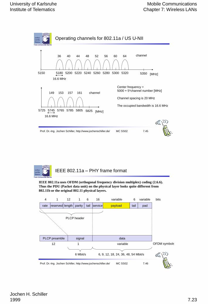
Operating channels for 802.11a / US U-NII
5150 [MHz]5180 53505200
36 44
16.6 MHz
Center frequency =
5000 + 5*channel number [MHz]
Channel spacing is 20 MHz
The occupied bandwidth is 16.6 MHz
channel40 48 52 56 60 64
149 153 157 161
5220 5240 5260 5280 5300 5320
5725 [MHz]5745 58255765
16.6 MHz
channel
5785 5805
Prof. Dr.-Ing. Jochen Schiller, http://www.jochenschiller.de/ MC SS02 7.46
IEEE 802.11a – PHY frame format
rate service payload
variable bits
6 Mbit/s
PLCP preamble signal data
OFDM symbols12 1 variable
reserved length tailparity tail pad
616611214 variable
6, 9, 12, 18, 24, 36, 48, 54 Mbit/s
PLCP header
IEEE 802.11a uses OFDM (orthogonal frequency division multiplex) coding (2.6.6).
Thus the PDU (Packet data unit) on the physical layer looks quite different from
802.11b or the original 802.11 physical layers.

University of Karlsruhe
Institute of Telematics
Mobile Communications
Chapter 7: Wireless LANs
Jochen H. Schiller
1999 7.24
Prof. Dr.-Ing. Jochen Schiller, http://www.jochenschiller.de/ MC SS02 7.47
WLAN: IEEE 802.11a
Data rate
6, 9, 12, 18, 24, 36, 48, 54 Mbit/s, depending on SNR
6, 12, 24 Mbit/s mandatory
Transmission range
100m outdoor, 10m indoor 54 Mbit/s up to 5 m,
48 up to 12 m,
36 up to 25 m,
24 up to 30m,
18 up to 40 m,
12 up to 60 m
Frequency
Free 5.15-5.25, 5.25-5.35, 5.725-5.825 GHz ISM-band
Security
Limited, WEP insecure,
Quality of Service
Typ. best effort, no guarantees (same as
all 802.11 products)
Special Advantages/Disadvantages
Advantage: fits into 802.x standards, free
ISM-band, available, simple system,
uses less crowded 5 GHz band
Disadvantage: stronger shading due to
higher frequency, no QoS
IEEE 802.11n
Prof. Dr.-Ing. Jochen Schiller, http://www.jochenschiller.de/ MC SS02 7.48
• OFDM
• MIMO
• 40 MHz channels
• 2.4 GHz (in fact also in the 5 GHz band)
• up to 600 Mbps
University of Karlsruhe
Institute of Telematics
Mobile Communications
Chapter 7: Wireless LANs
Jochen H. Schiller
1999 7.25
Prof. Dr.-Ing. Jochen Schiller, http://www.jochenschiller.de/ MC SS02 7.49
WLAN: IEEE 802.11 – some examples
802.11-2007: A new release of the standard that includes amendments
a, b, d, e, g, h, i & j. (July 2007)
802.11e: MAC Enhancements – QoS –
Enhance the current 802.11 MAC to expand support for applications with Quality of Service requirements, and in the capabilities and efficiency of the protocol.
802.11g: Data Rates at 2.4 GHz; 54 Mbit/s, OFDM, (backwards compatible with b) (2003)
802.11s: Mesh Networking, Extended Service Set (ESS) (June 2011)
802.11ad: Very High Throughput 60 GHz (~Dec 2012)
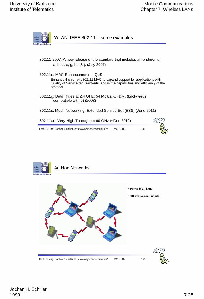
Ad Hoc Networks
Prof. Dr.-Ing. Jochen Schiller, http://www.jochenschiller.de/ MC SS02 7.50
• Power is an issue
• All stations are mobile
University of Karlsruhe
Institute of Telematics
Mobile Communications
Chapter 7: Wireless LANs
Jochen H. Schiller
1999 7.26
FL, UniK 4290: Introduction, 28.01.0851
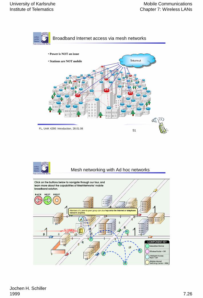
Broadband Internet access via mesh networks
• Power is NOT an issue
• Stations are NOT mobile
FL, UniK 4290: Introduction, 28.01.0852
Mesh networking with Ad hoc networks
University of Karlsruhe
Institute of Telematics
Mobile Communications
Chapter 7: Wireless LANs
Jochen H. Schiller
1999 7.27
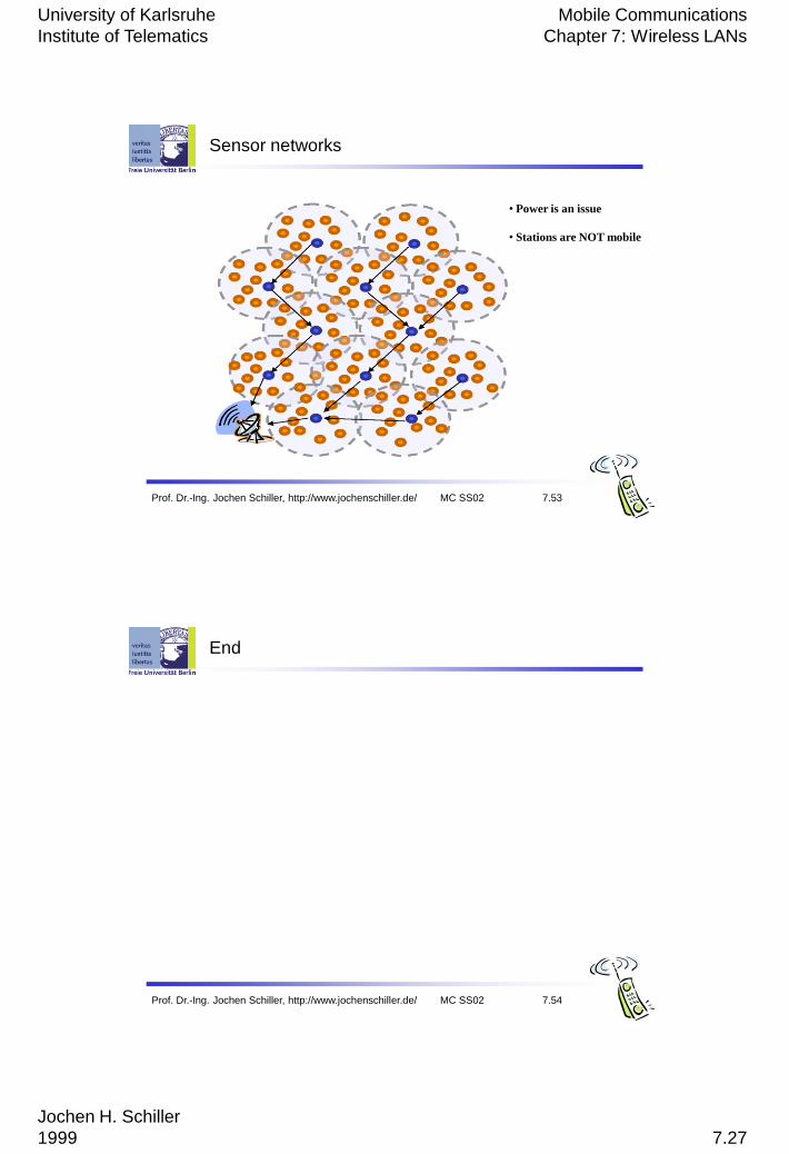
Sensor networks
Prof. Dr.-Ing. Jochen Schiller, http://www.jochenschiller.de/ MC SS02 7.53
• Power is an issue
• Stations are NOT mobile
Prof. Dr.-Ing. Jochen Schiller, http://www.jochenschiller.de/ MC SS02 7.54
End