Embed Size (px)
Citation preview
Progress In Electromagnetics Research C, Vol. 25, 27–40, 2012
EXPERIMENTAL RESULTS ON HIPERLAN/2 ANTEN-NAS FOR WEARABLE APPLICATIONS
S. Sankaralingam* and B. Gupta
Department of Electronics and Tele-Communication Engineering,Jadavpur University, Kolkata 700032, India
Abstract—This paper addresses the design and development ofHiperLAN antennas meeting the IEEE 802.11a standards for wearableapplications. Five such antennas are investigated for their performancecharacteristics, out of which three are conventional copper basedantennas and the remaining two are fully fabric antennas. The resultsreveal that all the proposed antennas are suitable for HiperLANapplications yielding antenna gain in the order of 7–11 dBi. This studydemonstrates that fully fabric antennas outperform the copper basedantennas.
1. INTRODUCTION
Communications on the human body is a relatively unexploredcommodity for the personal and mobile communications community.The military and the special services, such as fire-fighters, have beenusing on-body systems to support their users in various hazardousenvironments. A wearable antenna is an essential subsystem of anybody-centred Wireless LAN and therefore it plays a paramount role inoptimal design of any wearable system. The Wireless LAN devices usethe following ISM wavebands according to the IEEE 802.11 standards:
• Bluetooth 2450 MHz (IEEE 802.11b).• Hiper LAN 5800MHz (IEEE 802.11a).
Bluetooth ISM band ranges from 2400 MHz–2485 MHz. Bluetoothtechnology is aimed for short-range communication between all kindsof wireless devices within a range of 10 m. HiperLAN technologyoperates in the 5GHz frequency band using Orthogonal FrequencyDivision Multiplexing (OFDM) and offers many features like high
Received 27 August 2011, Accepted 14 October 2011, Scheduled 24 October 2011* Corresponding author: S. Sankaralingam ([email protected]).
28 Sankaralingam and Gupta
speed data transmission (up to 54Mbps), security support, mobilitysupport and increased range upto 50 m. HiperLAN/2 band rangesfrom 5725 MHz–5875MHz. For the wireless body-centric network tobe accepted by the public, wearable antennas need to be hidden andof low profile. This requires a possible integration of these systemswithin everyday clothing. Microstrip patch is a suitable candidate forany wearable application, as it can be made conformal for integrationinto clothing [1–3]. The aim of this paper is to design, develop and testthe performance characteristics of body-centric microstrip HiperLANantennas for ISM applications. Five antennas are considered —three copper based and two fully fabric antennas. The impedancecharacteristics of all the five antennas are studied and the radiationcharacteristics of one copper based and one fully fabric antennas aretested. All the five investigated antennas yield satisfactory results.
2. DESIGN AND DEVELOPMENT OF ANTENNAS
2.1. Design Aspects
The copper based antennas make use of copper for all their conductingparts whereas the fully fabric antennas utilize Zelt conductive fabric.Zelt fabric is more durable, tear resistant and can conform to anyshape. It can be cut and sewn like ordinary fabric to make protectiveclothing. The surface resistivity of Zelt is 0.01 ohms/sq and it canwithstand temperature up to 70◦C. Its thickness is 0.1613 mm. In allthe five cases of antennas, the polyester fabric is used as the dielectricsubstrate material. The value of dielectric constant of polyester fabricis 1.44 as measured by a novel technique proposed in [4] by theauthors of this manuscript. The design specifications of all the fiveantennas and the geometry used in each case are tabulated in Table 1.The detailed design procedure for a rectangular microstrip antennais outlined in [5, 6] and that for circular antenna in [7, 8]. The stepsinvolved in the design of a triangular patch antenna are listed in [9].
2.2. Modelling and Fabrication of Antennas
Modeling of antennas is performed using Method of Moments (MoM)based IE3D simulator [10] from Zeland Software Inc., USA. An infiniteground plane is assumed in the simulation so as to avoid back lobes inthe radiation patterns whereas the dimensions of the ground planein the fabricated antennas are taken as 120mm × 120mm. Thethicknesses of top signal layer and bottom ground plane are 0.1 mmand 0.5 mm respectively in the case of copper based antennas (1–3).The patch and ground plane of the antennas (1–3) are cut using CNC
Progress In Electromagnetics Research C, Vol. 25, 2012 29
Table 1. Design specifications of various antennas developed.
Design Copper based Electro-textile based
parameterAntenna
1
Antenna
2
Antenna
3
Antenna
4
Antenna
5
Geometry Rectangular Circular Triangular Rectangular Circular
Resonant
frequency(GHz)5.8 5.8 5.8 5.8 5.8
Substrate
dielectric constant1.44 1.44 1.44 1.44 1.44
Substrate
thickness (mm)2.85 2.85 2.85 2.85 2.85
Loss tangent of
the substrate0.01 0.01 0.01 0.01 0.01
Material used for
ground planeCopper Copper Copper Zelt Zelt
Material used
for patchCopper Copper Copper Zelt Zelt
machine so that the accuracy is about 20µm. Electro-textile basedantennas (4 and 5) use Zelt fabric for both patch and ground planewhose thickness is 0.1613 mm. Here again, the size of the ground planeis 120 mm × 120mm for antennas 4 and 5. The size of the insulatingfabric material in each case of the antenna is equal to that of groundplane. These insulating fabric pieces are stacked and stitched properlyto get required thickness. While assembling the antenna elements, thecopper sheets are just fixed on the dielectric fabric material with scotchtape and due care is taken such that there is no air gap between theinsulating fabric material and the conducting parts of the antenna.While assembling the fabric materials for making antennas 4 and 5,conducting threads may be used for stitching. While modeling thecoaxial probe feed to patch, the inner and outer diameters of theprobe are taken as 1.3 mm and 4.1 mm respectively corresponding tostandard 50 ohm SMA connector. A shorting pin of 1.0 mm diameteris connected at the centre of circular patch in order to suppress higherorder modes. The dimensions of rectangular antennas 1 and 4 arelength = 19.3 mm and width = 23.41 mm. The designed value ofradius of each of the circular radiating patches (antennas 2 and 5) is11.4mm. The side length of the triangular radiating patch (antenna 3)under investigation is 25.5mm. The feed position is optimized toget good matching characteristics (50 ohm impedance) at the center

30 Sankaralingam and Gupta
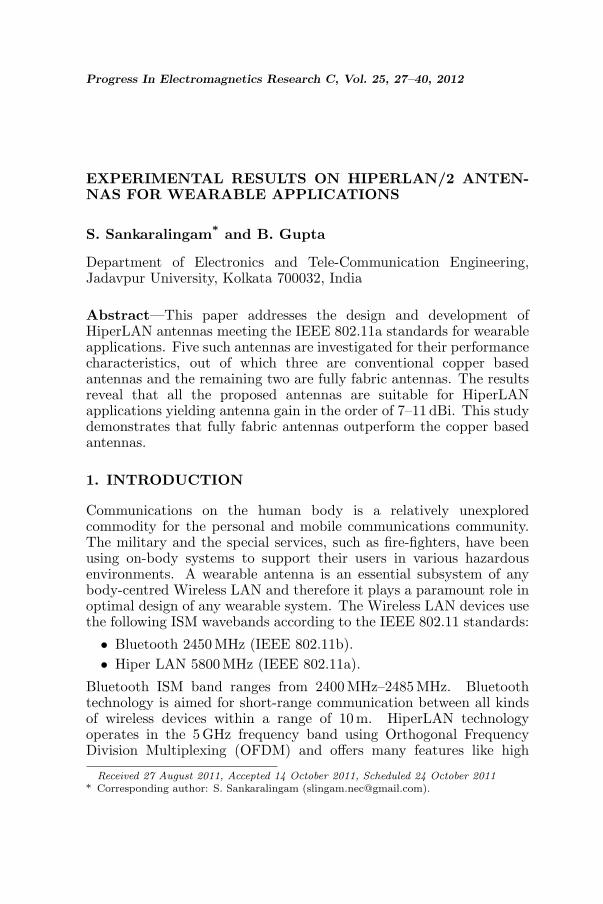
Figure 1. Photographs of HiperLAN antennas.
frequency. The optimized feed position for antennas 1 and 4 are 5.4 mmfrom the centre of the patch along the length direction. In case ofantennas 2 and 5, they are positioned at a radial distance of 4.5 mmand 5.4 mm respectively, from the centre of circular patch. For antenna3, it is located at a distance of 3.7 mm from the centroid of triangularshaped patch towards its apex. The photographs of all these fabricatedHiperLAN antennas are shown in Fig. 1.
3. IMPEDANCE CHARACTERISTICS
3.1. Simulated and Measured Results
Simulations and measurements are carried out over the frequency rangeof 5.2 GHz to 6.2 GHz for all five antennas 1–5 developed. Fig. 2shows simulated and measured S11 plots of HiperLAN antenna (#1) with rectangular geometry. As depicted by these simulationresults, this wearable antenna resonates at a frequency of 5.84 GHz

Progress In Electromagnetics Research C, Vol. 25, 2012 31
Figure 2. Return loss characteristics of antenna 1.
Figure 3. Return loss plot ofantenna 2.
Figure 4. Return loss plot ofantenna 3.
and exhibits a −10 dB return loss bandwidth of 574.85 MHz. Fig. 3corresponds to simulated and measured return loss characteristics ofthe wearable HiperLAN antenna (# 2) with circular geometry. Thisfigure reveals that the simulated values of resonant frequency andimpedance bandwidth of the antenna are 5.84GHz and 539.72 MHzrespectively. Referring to Fig. 4, it is seen that the triangularmicrostrip HiperLAN antenna (# 3) is simulated at a resonantfrequency of 5.8GHz with an impedance bandwidth of 432.76MHz.The measurements are done using a vector network analyzer (Model# 5071 B) from Agilent Technologies. Before measuring the impedanceparameters of the antennas under investigation, the network analyzer iscalibrated using the 2 port Ecal module [11], bearing model # 85092Cfor an operating frequency ranging from 5.2GHz to 6.2GHz, which
32 Sankaralingam and Gupta
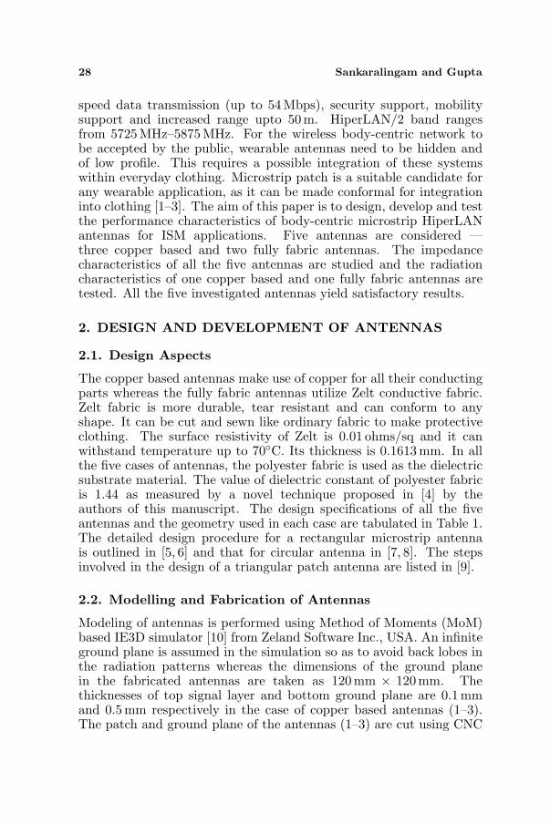
Figure 5. S11 plot of antenna 4. Figure 6. S11 plot of antenna 5.
provides excellent accuracy. Fabricated antenna (# 1) structure ismeasured for a resonant frequency of 5.775 GHz with an impedancebandwidth of 455.4 MHz having a return loss of −20.12 dB at theresonant frequency as shown in Fig. 2. Measured quantities ofresonant frequency and impedance bandwidth of antenna (# 2) are5.74GHz and 360 MHz respectively. Triangular microstrip antenna (#3) resonates at 5.775 GHz (return loss −17.76 dB) and yields animpedance bandwidth of 308.7 MHz as depicted in Fig. 4.
Figure 5 shows simulated and measured S11 plots of electro-textileHiperLAN antenna (# 4) with rectangular geometry. As depictedby these simulation results, this wearable antenna resonates at afrequency of 5.805GHz and exhibits a −10 dB return loss bandwidthof 571.82 MHz. Fig. 6 corresponds to simulated and measuredreturn loss characteristics of wearable HiperLAN antenna (# 5) withcircular geometry. This figure reveals that the simulated values ofresonant frequency and impedance bandwidth of antenna are 5.8 GHzand 558.6 MHz respectively. Fabricated antenna (# 4) structure ismeasured for a resonant frequency of 5.78 GHz with an impedancebandwidth of 292MHz having a return loss of −17.17 dB at theresonant frequency as shown in Fig. 5. Measured quantities of resonantfrequency and impedance bandwidth of antenna (# 5) are 5.91 GHzand 353 MHz respectively with a return loss of −20.85 dB (Fig. 6).
3.2. Discussions
Measured results are tabulated in Table 2 along with the correspondingtheoretical predictions for all five antennas studied. The deviationbetween simulated and measured resonant frequencies is 1.1% incase of antenna 1; 1.71% and 0.0043% in case of antennas 2 and 3
Progress In Electromagnetics Research C, Vol. 25, 2012 33
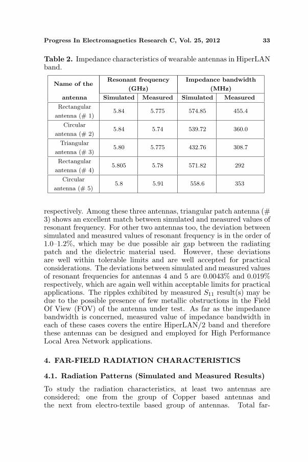
Table 2. Impedance characteristics of wearable antennas in HiperLANband.
Name of theResonant frequency
(GHz)
Impedance bandwidth
(MHz)
antenna Simulated Measured Simulated Measured
Rectangular
antenna (# 1)5.84 5.775 574.85 455.4
Circular
antenna (# 2)5.84 5.74 539.72 360.0
Triangular
antenna (# 3)5.80 5.775 432.76 308.7
Rectangular
antenna (# 4)5.805 5.78 571.82 292
Circular
antenna (# 5)5.8 5.91 558.6 353
respectively. Among these three antennas, triangular patch antenna (#3) shows an excellent match between simulated and measured values ofresonant frequency. For other two antennas too, the deviation betweensimulated and measured values of resonant frequency is in the order of1.0–1.2%, which may be due possible air gap between the radiatingpatch and the dielectric material used. However, these deviationsare well within tolerable limits and are well accepted for practicalconsiderations. The deviations between simulated and measured valuesof resonant frequencies for antennas 4 and 5 are 0.0043% and 0.019%respectively, which are again well within acceptable limits for practicalapplications. The ripples exhibited by measured S11 result(s) may bedue to the possible presence of few metallic obstructions in the FieldOf View (FOV) of the antenna under test. As far as the impedancebandwidth is concerned, measured value of impedance bandwidth ineach of these cases covers the entire HiperLAN/2 band and thereforethese antennas can be designed and employed for High PerformanceLocal Area Network applications.
4. FAR-FIELD RADIATION CHARACTERISTICS
4.1. Radiation Patterns (Simulated and Measured Results)
To study the radiation characteristics, at least two antennas areconsidered; one from the group of Copper based antennas andthe next from electro-textile based group of antennas. Total far-

34 Sankaralingam and Gupta
field radiation patterns of electromagnetically modeled antennas 3,in both principal planes of φ = 0◦ (x-z) and φ = 90◦ (y-z),are obtained at its corresponding simulated resonant frequency of5.8GHz. Fabricated triangular microstrip antenna (# 3) is subjectedto far-field radiation pattern measurements at its correspondingmeasured resonant frequency (5.775GHz) in a rectangular shieldedanechoic chamber. Simulated and measured far-field patterns of thistriangular shaped wearable antenna (# 3) are shown in Figs. 7(a)–
(a)
(b) (c)
Figure 7. (a)–(c) Radiation patterns of triangular shaped wearableHiperLAN antenna.
Progress In Electromagnetics Research C, Vol. 25, 2012 35
(c). Referring to radiation patterns of the fabricated antenna (# 3), itis understood that the values of discrimination between co-polar andcross polar components in azimuth and elevation planes are 8.5 dB and12.19 dB respectively. These values are reasonably good for practicalapplications. Simulated values of 3 dB beam-width in the x-z and y-zplanes of this antenna are 73.25◦ and 83.09◦ respectively. Measured3 dB beam-width values in azimuth and elevation planes, as obtainedfrom the corresponding radiation pattern plots, are 77◦ and 73◦.
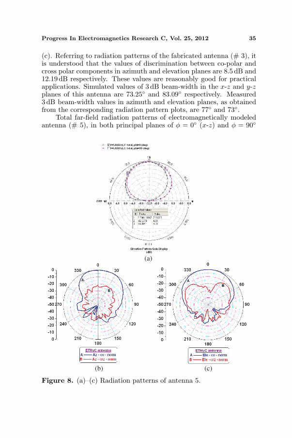
Total far-field radiation patterns of electromagnetically modeledantenna (# 5), in both principal planes of φ = 0◦ (x-z) and φ = 90◦
(a)
(b) (c)
Figure 8. (a)–(c) Radiation patterns of antenna 5.
36 Sankaralingam and Gupta
(y-z), are obtained at its simulated resonant frequency of 5.8 GHz.Fabricated circular microstrip antenna (# 5) is subjected to far-fieldradiation pattern measurements at its measured resonant frequency.Simulated and measured far-field patterns of this circular shapedwearable antenna (# 5) are shown in Figs. 8(a)–(c). Referring toradiation patterns of this antenna, it is understood that the valuesof discrimination between co-polar and cross polar components inazimuth and elevation planes of the fabricated wearable antenna (#5) are 23.44 dB and 28.7 dB respectively. These values are reasonablygood for practical applications. Simulated values of 3 dB beamwidth inthe principal planes of this antenna are 71.38◦ and 78.31◦ respectively.Measured 3 dB beam-width values in azimuth and elevation planes, asobtained from the corresponding radiation pattern plots, are 70◦ and73◦ respectively.
(a) (b)
(c) (d)
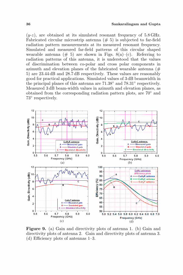
Figure 9. (a) Gain and directivity plots of antenna 1. (b) Gain anddirectivity plots of antenna 2. Gain and directivity plots of antenna 3.(d) Efficiency plots of antennas 1–3.
Progress In Electromagnetics Research C, Vol. 25, 2012 37
4.2. Gain, Directivity and Efficiency
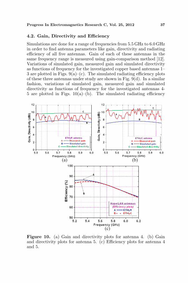
Simulations are done for a range of frequencies from 5.5 GHz to 6.0 GHzin order to find antenna parameters like gain, directivity and radiatingefficiency of all five antennas. Gain of each of these antennas in thesame frequency range is measured using gain-comparison method [12].Variations of simulated gain, measured gain and simulated directivityas functions of frequency for the investigated copper based antennas 1–3 are plotted in Figs. 9(a)–(c). The simulated radiating efficiency plotsof these three antennas under study are shown in Fig. 9(d). In a similarfashion, variations of simulated gain, measured gain and simulateddirectivity as functions of frequency for the investigated antennas 4-5 are plotted in Figs. 10(a)–(b). The simulated radiating efficiency
(a) (b)
(c)
Figure 10. (a) Gain and directivity plots for antenna 4. (b) Gainand directivity plots for antenna 5. (c) Efficiency plots for antenna 4and 5.
38 Sankaralingam and Gupta
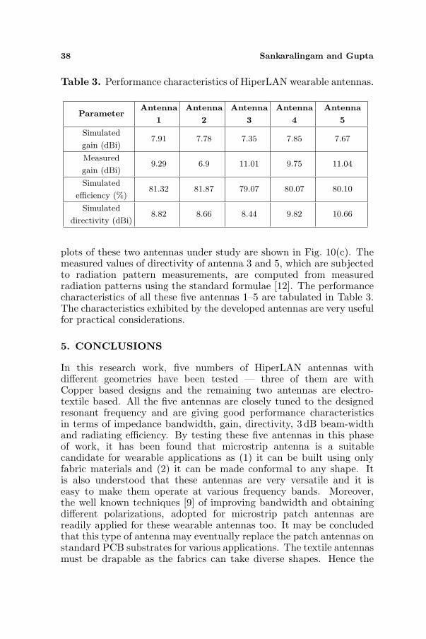
Table 3. Performance characteristics of HiperLAN wearable antennas.
ParameterAntenna
1
Antenna
2
Antenna
3
Antenna
4
Antenna
5
Simulated
gain (dBi)7.91 7.78 7.35 7.85 7.67
Measured
gain (dBi)9.29 6.9 11.01 9.75 11.04
Simulated
efficiency (%)81.32 81.87 79.07 80.07 80.10
Simulated
directivity (dBi)8.82 8.66 8.44 9.82 10.66
plots of these two antennas under study are shown in Fig. 10(c). Themeasured values of directivity of antenna 3 and 5, which are subjectedto radiation pattern measurements, are computed from measuredradiation patterns using the standard formulae [12]. The performancecharacteristics of all these five antennas 1–5 are tabulated in Table 3.The characteristics exhibited by the developed antennas are very usefulfor practical considerations.
5. CONCLUSIONS
In this research work, five numbers of HiperLAN antennas withdifferent geometries have been tested — three of them are withCopper based designs and the remaining two antennas are electro-textile based. All the five antennas are closely tuned to the designedresonant frequency and are giving good performance characteristicsin terms of impedance bandwidth, gain, directivity, 3 dB beam-widthand radiating efficiency. By testing these five antennas in this phaseof work, it has been found that microstrip antenna is a suitablecandidate for wearable applications as (1) it can be built using onlyfabric materials and (2) it can be made conformal to any shape. Itis also understood that these antennas are very versatile and it iseasy to make them operate at various frequency bands. Moreover,the well known techniques [9] of improving bandwidth and obtainingdifferent polarizations, adopted for microstrip patch antennas arereadily applied for these wearable antennas too. It may be concludedthat this type of antenna may eventually replace the patch antennas onstandard PCB substrates for various applications. The textile antennasmust be drapable as the fabrics can take diverse shapes. Hence the
Progress In Electromagnetics Research C, Vol. 25, 2012 39
bending effects on the performance characteristics of these antennasare to be taken into account when they are designed for wearableapplications. The authors have already studied these phenomena withWLAN antennas, as reported in [5]. Moreover, the interaction betweenthe wearable antenna and the human body can never be avoided andtherefore, it requires further investigations.
ACKNOWLEDGMENT
The authors would like to thank Prof. P. Mohanan (Cochin Universityof Science and Technology, India), and Dr. T. Balakrishnan (Centre forAirborne Systems, Defence Research and Development Organization,India) for the help with the measurement of radiation pattern andgain; V. P. Sarin, R. Sujith, G. Prabhu Shankar, and Sanjay Manzhifor the assistance during antenna pattern measurements; Vishal Gupta(Agilent Technologies, New Delhi, India) and A. Senthil (AgilentManufacturers’ Representative, Chennai, India) for the constructivesuggestions.
REFERENCES
1. Salonen, P. and L. Hurme, “A novel fabric WLAN antennafor wearable applications,” Proceedings of IEEE Antennas andPropagation Society International Symposium, Vol. 2, 700–703,Jun. 2003.
2. Salonen, P. and H. Hurme, “Modeling of a fabric GPS Antennafor Wearable Applications,” Proceedings of IASTED InternationalConference Modeling and Simulation, Vol. 1, 18–23, 2003.
3. Tanaka, M. and J. H. Jang, “Wearable microstrip antenna,” Pro-ceedings of IEEE Antennas and Propagation Society InternationalSymposium and URSI North American Radio Science Meeting,Columbus, OH, USA, Jun. 2003.
4. Sankaralingam, S. and B. Gupta, “A novel technique fordetermination of dielectric constant of fabric materials forwearable antennas,” Proceedings of International Conference onNear-Field Characterization and Imaging (ICONIC), Vol. 1, 247–250, Taipei, Taiwan, Jun. 2009.
5. Sankaralingam, S. and B. Gupta, “Development of textileantennas for body wearable applications and investigationson their performance under bent conditions,” Progress InElectromagnetics Research B, Vol. 22, 53–71, 2010.
40 Sankaralingam and Gupta
6. Sankaralingam, S. and B. Gupta, “Performance study of ablue tooth antenna for wearable applications,” Proceedings ofInternational Symposium on Antennas and Propagation (ISAP),Vol. 1, Bangkok, Oct. 2009.
7. Sankaralingam, S. and B. Gupta, “A circular disk microstripWLAN antenna for wearable applications,” Proc. of IEEE IndiaConference (INDICON), Vol. 1, 513–516, Ahmedabad, India,Dec. 2009.
8. Sankaralingam, S. and B. Gupta, “A bluetooth antenna foron-body communications,” Proceedings of the Fourth EuropeanConference on Antennas and Propagation (EuCAP), Barcelona,Spain, Apr. 2010.
9. Garg, R. and P. Bhartia, Inder Bahl and Apisak Ittipiboon,Microstrip Antenna Design Handbook, Artech House Publishers,2001.
10. IE3D Electromagnetic Simulator from Zeland Software Inc., USA,Release 10.12, 2004.
11. Internet resources, Applying Error Correction to NetworkAnalyzer Measurements, Agilent application note 5965-7709E,Mar. 27, 2002, Available: http://www.home.agilent.com.
12. Kraus, J. D., R. J. Marhefka, and A. S. Khan, “Antennas for allapplications,” 3rd edition, 24–25, Tata McGraw-Hill PublishingCompany Ltd., New Delhi, 2006.