Embed Size (px)
Citation preview
7/27/2019 MnO2 -Doped PPy Supercapaci.
http://slidepdf.com/reader/full/mno2-doped-ppy-supercapaci 1/6
Electrochimica Acta 53 (2008) 7690–7695
Contents lists available at ScienceDirect
Electrochimica Acta
j o u r n a l h o m e p a g e : w w w . e l s e v i e r . c o m / l o c a t e / e l e c t a c t a
Manganese oxide embedded polypyrrole nanocomposites for
electrochemical supercapacitor
R.K. Sharma, A.C. Rastogi 1, S.B. Desu ∗,1
201, Marcus Hall, Department of Electrical and Computer Engineering, University of Massachusetts, Amherst, MA 01003, USA
a r t i c l e i n f o
Article history:
Received 1 March 2008
Received in revised form 31 March 2008
Accepted 2 April 2008
Available online 18 April 2008
Keywords:
MnO2 nanocomposite
Polypyrrole
Supercapacitor
Specific capacitance
a b s t r a c t
MnO2 embedded PPy nanocomposite (MnO2/PPy) thin film electrodes were electrochemically syn-thesized over polished graphite susbtrates. Growing PPy polymer chains provides large surface area
template that enables MnO2 to form as nanoparticles embeded within polymer matrix. Co-deposition
of MnO2 and PPy has a complimentary action in which porous PPy matrix provides high active surface
area for the MnO2 nanoparticles and, on the other hand, MnO 2 nanoparticles nucleated over polymer
chains contribute to enhanced conductivity and stability of the nanocomposite material by interlinking
the PPy polymer chains. The MnO2/PPy nanocomposite thin film electrodes show significant improve-
ment in the redox performance as cyclic voltammetric studies have shown. Specific capacitance of the
nanocomposite is remarkably high (∼620Fg−1) in comparision to its constituents MnO2 (∼225Fg−1)
and PPy (∼250Fg−1). Photoelectron spectroscopy studies show that hydrated manganese oxide in the
nanocomposite exists in the mixed Mn(II) to Mn(IV) oxidation states. Accordingly, chemical structures of
MnO2 and PPy constituents in the nanocomposite are not influenced by the co-deposition process. The
MnO2/PPy nanocomposite electrode material however shows significantly improved high specific capac-
itity, charge–discharge stability and the redox performance properties suitable for applicationin the high
energy density supercapcitors.
© 2008 Published by Elsevier Ltd.
1. Introduction
Electrochemical supercapacitor is a charge storage device that
can withstand higher power compared to the battery, and deliver
higher energy compared to the conventional or electrolytic capac-
itor [1–3]. Supercapacitors are classified into two types based
on their charge storage mechanism; electrical double layer (EDL)
capacitors and the pseudo-capacitors. Energy storage in EDLC is
due to charging of the electrical double layer at the electrode and
electrolyte interface however a pseudo-capacitor utilizes faradic
reactions in addition to double layer charge. Carbon materials have
been widely investigated for ELD capacitor whereas the charge
storage in such materials is limited due to electrostatic in origin.
Redox metal oxides (RuO2 and MnO2) have shown high perfor-
mance as electrode material in supercapacitor [4–8]. The high
cost, low porosity and rapid decrease of power density at high
∗ Corresponding author. Tel.: +1 607 777 4030; fax: +1 607 777 4822.
E-mail addresses: [email protected] (R.K. Sharma),
[email protected] , [email protected] (A.C. Rastogi),
[email protected], [email protected] (S.B. Desu).1 Present address: Department of Electricaland ComputerEngineering,Bingham-
ton University, State University of New York, Binghamton, NY 13902, USA.
charge discharge rates however are disadvantages of using RuO2.
In recent years increasing attention is given to the hydrous man-
ganese oxides (MnO2· xH2O). The specific capacitance reported for
MnO2 is ∼250Fg−1 and a high capacitance (∼1370Fg−1) is pro-
jected at very low loading levels when the material utilization is
high [9,10]. There are efforts to enhance the material utilization by
using large area supports or byforming composites of MnO2 [11,12].
Directdeposition of MnO2 on carbonblacks with large surface area,
nanotubes, activated or meso porous carbons have been studied to
increase active surface area of MnO2 [11–15]. The large area sup-
ports areeffectively shown topreventthe MnO2 agglomerationand
thus keeping a high active surface area of the adsorbed material.
Besides providing the support, carbon materials with large sur-
face area (∼2500m2/g) could also store higher charge and thus
have been widely investigated for EDL capacitors [16,17]. However,
application of carbonmaterials in EDLC is limited dueto the micro-
pores that are not easily wetted by electrolytes and a large part of
the exposed carbon surface may not be utilized for charge storage
[18]. Furthermore, carbonmaterial is also found to sufferfrom slow
deterioration by oxidation which increases internal resistance [1].
In contrast to the existence of various oxidation structures,
conducting polymers have appeared as a potentchoice forsuperca-
pacitor electrode material [1,2,19]. Polypyrrole (PPy), an important
conducting polymer has been successfully employed as redox
0013-4686/$ – see front matter © 2008 Published by Elsevier Ltd.
doi:10.1016/j.electacta.2008.04.028
7/27/2019 MnO2 -Doped PPy Supercapaci.
http://slidepdf.com/reader/full/mno2-doped-ppy-supercapaci 2/6
R.K. Sharma et al. / Electrochimica Acta 53 (2008) 7690–7695 7691
electrode material [20–22]. In spite of the high charge storage
capabilities, PPy and other conducting polymers are lacking in
long-term stability and mechanical properties [23]. A unique com-
bination of the metal oxide particulates dispersedover large surface
area with conducting polymer as support appears interesting
for supercapacitor electrodes. In the present work, we report on
the nanostructured MnO2 particles embedded within PPy matrix
(MnO2
/PPy) as a composite electrode material prepared by the
electrochemical co-deposition technique. In the past composites
of redox metal oxides have been prepared by several methods like
physical mixing or dispersion in the solution; however we show
by the electrochemical co-deposition process for MnO2 and PPy
in which Mn2+ ions were provided in the monomer pyrrole solu-
tion during galvanostatic polymerization can effectively produce
a nanocomposite material. The process basically involves anodic
growth of two different chemical entities; polypyrrole by polymer-
ization and the anodic oxidative deposition of MnO2 nanoparticles
which become electro-embedded within the growing polypyrrole
polymeric chain structures. Electrochemical performance of these
two chemical entities is interrelated and has a complimentary
action. PPy provides enormously large surface area for dispersion
that helps MnO2 to grow in the form of nanosize particles with a
high active surface area forredox processing.In turn, theMnO2 par-
ticles provide a rigidsupport and a percolated electrical conducting
path to PPy by interlinking the polymer chains thus providing
improved charge exchange efficiency and stability during redox
cycling. This paper reports on the synthesis, electrochemical and
morphological properties of the MnO2/PPy nanocomposite elec-
trodes for the supercapacitors.
2. Experimental
High purity chemicals; the pyrrole monomer, MnSO4·5H2O,
Na2SO4 salts and H2SO4 solvent were procured from Aldrich.
Deionised water was used to prepare the electrochemical solu-
tions for electrodic film growth and characterization. Monomerpyrrole (0.1 M) in 0.5 M H2SO4 was used for the growth of polymer
film. To deposit MnO2/PPy nanocomposite films, electrochemical
polymerization of pyrrole and MnO2 layer formation were simul-
taneously carried out by adding 0.2 M MnSO4 to the solution. All
the potentials were measured against saturated Ag/AgCl refer-
ence using platinum plate as counter electrode. Polished graphite
plates (1cm2) were used as working electrode. MnO2/PPy was
electrochemically co-deposited under galvanostatic conditions by
applying constant current density (4 mAcm−2) for a fixed duration
200s. Pure MnO2 and PPy electrodes were also electrodeposited
from the solutions carrying Mn or PPy precursors separately as
reference material to the MnO2/PPy nanocomposite. Deposition
current density, electrolyte pH and the growth time was kept iden-
tical for each deposition and the amount of total charge used in the
film growth was kept constant. Followed by the growth, electrodes
were rinsed in deionised water and dried prior to electrochemical
evaluation of specific capacitance by cyclic voltammetry in 0.5 M
Na2SO4 solution. The electrodes were tested between −0.5 and
0.5V (Ag/AgCl) in three-electrode electrochemical cell usingpoten-
tiostat (Solartron model 1260). Chemical composition and surface
microstructure of the electrodic deposits were analyzed by X-ray
photoelectronspectroscopy(XPS) and fieldemissionscanning elec-
tron microscope (FESEM).
3. Results and discussion
Specific capacitance of the deposited materials was evaluated
by cyclic voltammetric analysis in 0.5 M Na2SO4 solution. Cyclic
Fig.1. Cyclic voltammogram(a)PPy,(b) hydrousMnO2 and (c)MnO2/PPy nanocom-
posite electrode at 50 mV s−1 in 0.5M Na2 SO4.
voltammograms recorded for hydrous MnO2, PPy and PPy/MnO2composite electrodeare shownin Fig.1. PPy/MnO2 compositeelec-
trodeexhibitshigh output current in comparision to theelectrodes
of MnO2 and PPy prepared under identical conditions. Typically,
the PPy/MnO2 composite electrode showed much higher specific
capacitance (∼600Fg−1) when compared to 200–250 F g−1 of the
electrodes made by the constituent materials. The enhancement in
thecharge strorage capacity of the composite material is attributed
to the structural modifications of constituents MnO2 and PPy as
shown later. Deviation from rectangular shape of voltammogram
of MnO2/PPy nanocomposite is due to polarization resistance.
The XPS surface scan spectra of the PPy/MnO2 composite
film deposited over Pt substrate after having been subjected to
the oxidation–reduction cycle in a 0.5M Na2SO4 aqueous elec-
trolytewas studied.Formation of the nanocompositeby manganese
oxide incorporation within electro-polymerized PPy is evidenced
by manganese Mn2p3/2 and satellite Mn2p1/2 along with oxy-
gen O1s XPS peaks as shown in Figs. 2 and 3. An assessment of
the Mn-oxide component contribution to the pseudo-capacitance
towards improving the overall electrochemical performance of the
nanocomposite electrode requires a precise knowledge of the oxi-
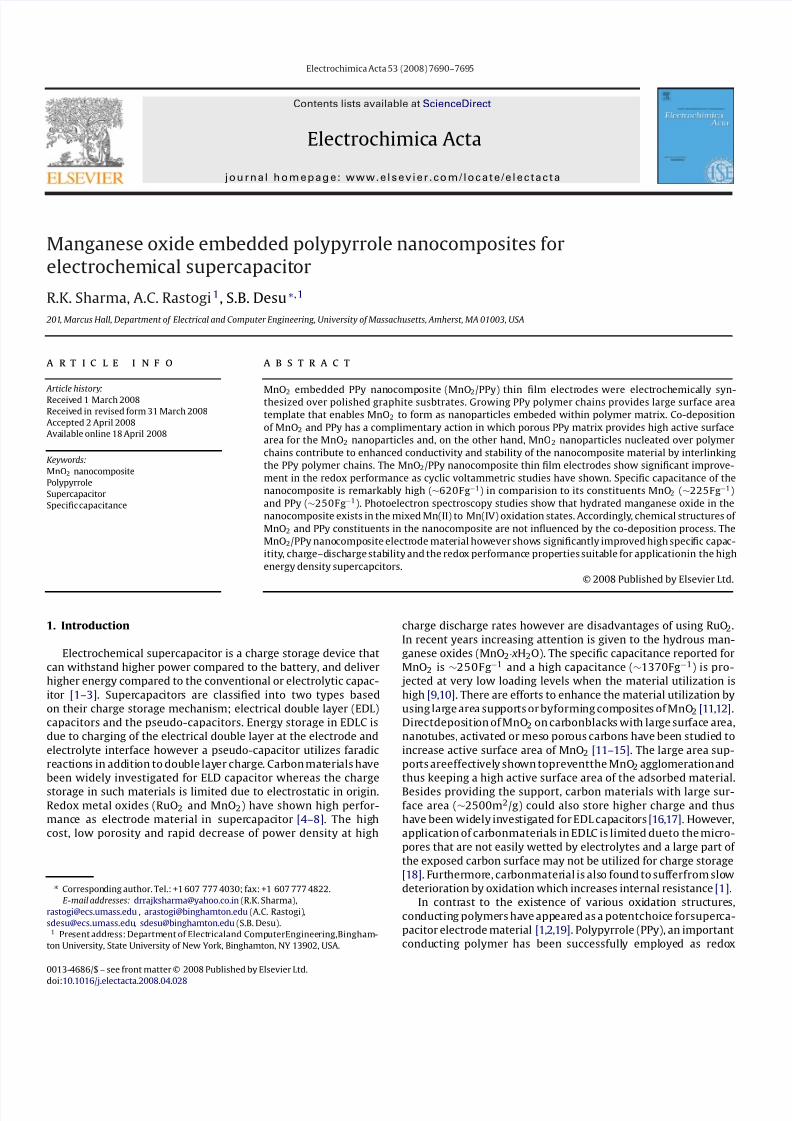
Fig. 2. Mn2p core level XPS spectra showing existence Mn(II) and Mn(IV) in the
MnO2/PPy nanocomposite film.
7/27/2019 MnO2 -Doped PPy Supercapaci.
http://slidepdf.com/reader/full/mno2-doped-ppy-supercapaci 3/6
7692 R.K. Sharma et al. / Electrochimica Acta 53 (2008) 7690–7695
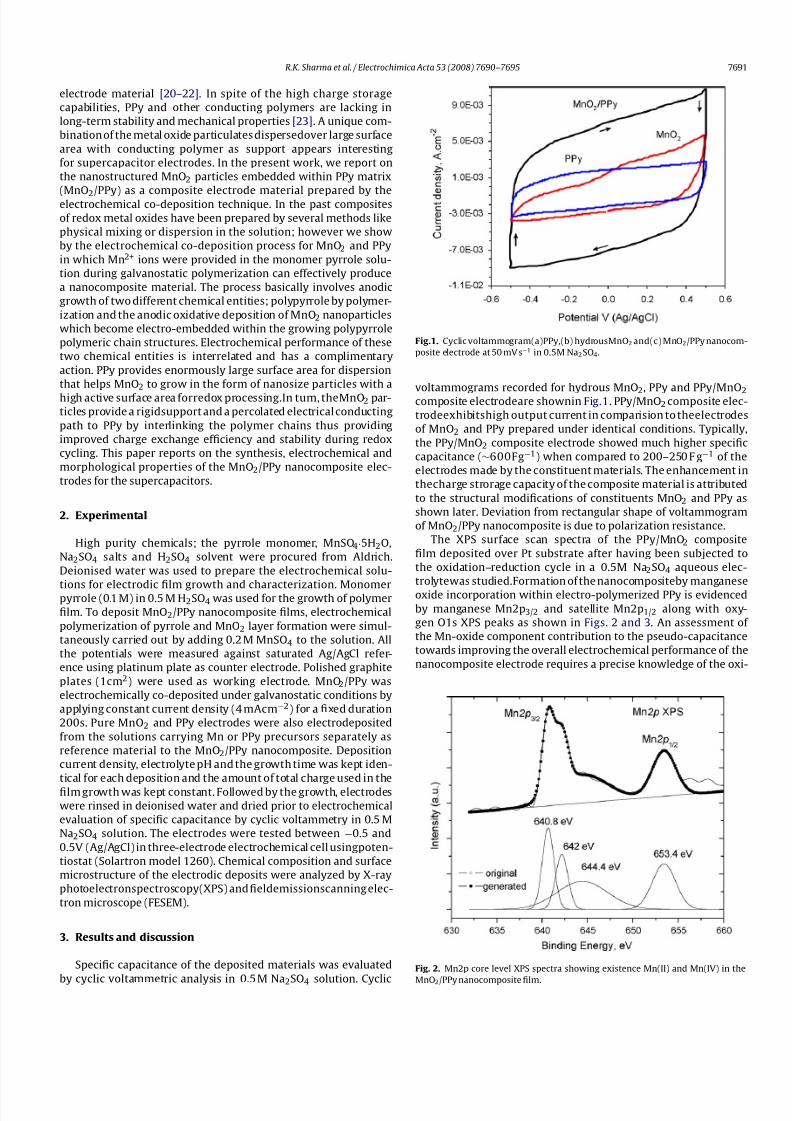
Fig. 3. O1s core level XPS spectra and deconvoluted peak positions corresponding
to Mn–O, Mn–OH and SO42− bonded oxygen in MnO2/PPy nanocomposite film.
dation state of Mn. The Mn2p and O1s core level spectra were
therefore analyzed to determine Mn-oxide phases present within
PPy matrix. The Mn2p3/2 and Mn2p1/2 transitions are centered at
642 and 653.4 eV, respectively, as shown in Fig. 2. Contributions
from different Mn species were distinguishedby curve fitting using
the Lorentz–Gaussian profile procedure. Deconvoluted Mn2p3/2
peaks at 640.8 and 642.0 eV having spin energy separation of 12.6
and 11.4 eV with the satellite Mn2p1/2 peak are attributed to the
presence of Mn(II) and Mn(IV) oxide phases, respectively, consis-
tent with the reported data for Mn3O4 and MnO2 [24]. Existence
of the Mn-oxide phases is also reflected in the O1s core level
spectra shown in Fig. 3. The binding energy separation between
the O1s oxide component peak and the Mn2p3/2 peak for Mn(IV)
is ∼112.0 eV which is an indication of Mn–O–Mn bonding struc-
ture [25,26]. The Mn(II) to Mn(IV) ratio in the film is ∼1:1.39 as
determined from thearea under theXPS peaks. Aqueous electrode-
position studies reported earlier [25] show growthof stable Mn3O4
and MnO2 films occur in two different potential regimes. In the
present case, initial electro-polymerized PPy nanocomposite film
probably contained mostly MnO2 phase because the electrodepo-
sition conditions favored it. The Mn(IV) is reduced to Mn(II) during
the electrical analysis of the nanocomposite supercapacitor while
undergoing the electrochemical dedoping step. Since both Mn(II)
andMn(IV) phases coexist, theelectrodeperhaps represents a state
of incomplete reduction step. These observations suggest that nan-
odispersed MnO2 within the PPy matrix also actively participates
in the redox pseudo-capacitive reaction with the involvement of
the ionic species from the Na2SO4 electrolyte used in the study
of the supercapacitor made from such electrodes. Similar results
were inferred from MnO2 based supercapacitors [10]. Clearly, the
nanodispersed MnO2 also contributes to the charge storage simul-
taneously to the PPy conducting polymer. This aspect is further
discussed in later sections.
Deconvolution of the O1s XPS spectra (Fig. 3) indicates three
different oxygen bonding configurations, such as Mn–O–Mn oxide
bonding at 530.3eV, Mn–OH hydroxyl bond at 531.2eV andH–O–H
molecule or SO42− bonded oxygen at 532.1 eV [25]. A substan-
tial fraction 43.5% of the mean oxygen concentration in the film
determined from XPS O1s peak is bonded as SO42−. In conjunction
with the sulphur (S) concentration at 14.2% determined from S2p
XPS peak, this indicates high concentration of SO42− ions trapped
within the MnO2 embedded PPy nanocomposite electrode system
as expected for the nanocomposite electrodein the oxidative (dop-
ing) state. During the PPyelectrodedoping process Mn(II) oxidation
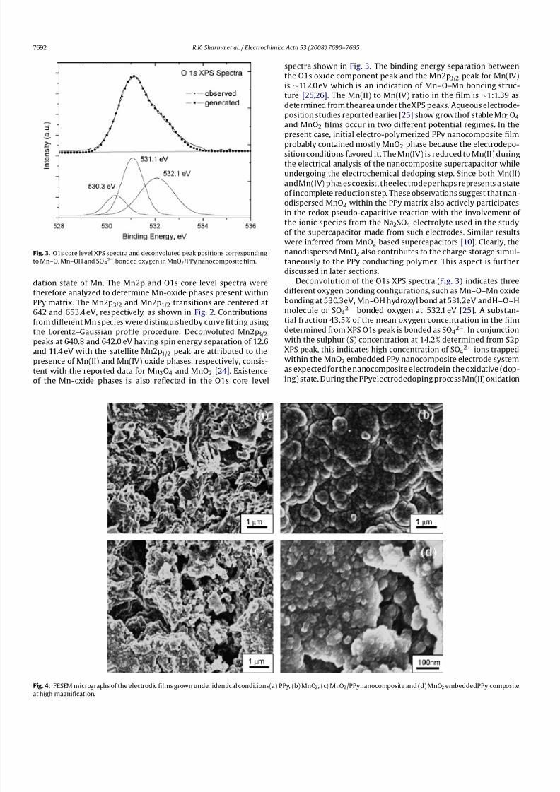
Fig. 4. FESEM micrographs of the electrodic films grown under identical conditions(a) PPy, (b) MnO2, (c) MnO2/PPynanocomposite and (d) MnO2 embedded PPy composite
at high magnification.
7/27/2019 MnO2 -Doped PPy Supercapaci.
http://slidepdf.com/reader/full/mno2-doped-ppy-supercapaci 4/6
R.K. Sharma et al. / Electrochimica Acta 53 (2008) 7690–7695 7693
to Mn(IV) involves complex intermediate steps such as forma-
tion of Mn(II) hydroxide, Mn–O–OH or Mn-(OH)2 polymorphs
instead of direct MnO2 as described in some earlier studies [27].
Proton promoted reaction of Mn–O–OH, Mn–(OH)2 in the acidic
medium produces MnO2 [28]. Oxygen present as O–H basically
represents intermediate Mn–O–OH stage. The relative intensity of
the three oxygen bonded structures indicates a transitional pro-
cess of Mn-oxide between the reduction and re-oxidation states.
As inferred earlier, pseudo-capacitance storage due to change in
valence state of Mn contributes to the overall high specific capaci-
tance∼620Fg−1 of the nanocomposite electrode.
Porosityof the electrochemical electrodeis an importantparam-
eter for attaining high charge density by area enhancement. The
FESEM micrograph of (a) PPy, (b) hydrous manganese oxide and
(c) the MnO2/PPy nanocomposite prepared under indentical con-
ditions of current density and growth time are presented in Fig. 4.
Electro-polymerized PPy film show highly porous morphology as
seen by the micrograph (a). Such polymer morphology of elec-
tro polymerized PPy has been reported by other groups as well
[29]. The morphology of the electrodeposited manganese oxide
shown in micrograph (b) is relatively dense with a cauliflower
like agglomerated clusters of MnO2 particles. Micrograph (c) for
the MnO2/PPy nanocomposite shows remarkable features which
is basically dominated by PPy morphology and the MnO2, rather
than forming a dense microstructure as in the micrograph (b)
is seen embeded in PPy scaffold in the form of ∼100nm nodu-
lar grains. The high magnification picture (micrograph (d)) clearly
show the MnO2 nanograins embeded in PPy. The MnO2/PPy
nanocomposite morphology observed in Fig. 4 (micrograph c
and d) clearly show the evolution of large surface area of the
co-deposited MnO2.Considering the voltammometric response,
composition analysis and the morphological features in Figs. 1–4,
itis inferred thatthe PPy and MnO2 have complimentry action dur-
ing the growth of electrodic film and its redox cycling. During the
growth of MnO2/PPy nanocomposite electrode by electrochemcial
co-deposition, the PPy due to its porous morphology provides a
large surface to the growing MnO2 enabling a high active surfaceareaof the MnO2 particles.Simultaneously,the nucleation of MnO2
nanoparticles over growing polypyrrole chains terminates its fur-
ther growth by attachment and gives rise to a fresh nucleation of
PPy chain on the same or at another site. PPy structure is an impor-
tant parameter as the shorter and ordered polymer structure are
found to be ideal structures for charge storage [30]. Furthermore,
the presence of MnO2 in PPy scaffold enhances the conductivity
of composite by cross linking the PPy chains. This significantely
reduces the chain defects responsible for hopping conduction [31].
Additionally, the MnO2 particle clusters in the polymer matrix
essentially provide rigid support for stability of the PPy chains dur-
ing redox cycling. The pseudo-capacitance of MnO2 significantly
dependsonthesurfaceatomsandintheMnO2/PPy nanocomposite,
the available large surface of supported/embeded MnO2 nanopar-ticles significantly contribute to the overall capacitance. Therefore,
thelarge surface areaof theembeded MnO2 nanoparticles as wellas
structurally modified PPy polymer chains due to MnO2 nucleation
both contribute to the high specific capacitance of the nanocom-
posite synthesized by electrochemical co-deposition.
Asdiscussedearlier, basedon XPSdatain Fig.2, inthePPydoping
process Mn(II) oxidation to Mn(IV) through complex intermediate
steps involvesformation of hydrousMn(II) hydroxide,Mn–O–OH or
Mn–(OH)2 polymorphs insteadof direct MnO2.Inearlierreportsthe
redox process of Mn is shown toinvolve the (III) and the (IV) oxida-
tion statesof Mn [10], however in the present co-deposition process
nanoMnO2 allowed redox involvement of Mn(II) and Mn(IV) oxi-
dation states. The phase change of MnO2 to various oxidation
states of hydrous manganese oxides is associated with the electron
exchange, therefore the redox process between Mn(II) and Mn(IV)
instead of Mn(III) and Mn(IV) involves an additional oxidation state
and consequently an improved charge storage capacity.
There are two mechanisms proposed for charge storage in
faradic redox supercapacitor electrodes. The first is based on the
intercalation of H+ or Na+ ions in the electrode during reduction
and deintercalation on oxidation [1,6].
MnO2 +H++e−↔ MnOOH (1)
The other is adsorption of cations on the electrode surface from
electrolyte.
(MnO2)surface+C++e−↔ (MnO2−C+)surface (2)
The redox processes in polypyrrole involve mass and resistance
change as well as electron transitions unlike the other redox sys-
tems in electrochemistry where only electrons are involved. The
oxidation of polypyrrole called doping, yields a charged polymer
film with incorporated anions and during reduction (dedoping)
these anions are expelled. Polypyrrole contains a cationic polymer
backbone,hencethe PPyunits havea positive charge andthe anions
are usedas charge compensating ionin redox process. It is interest-
inginMnO2/PPy compositethatthe charge storage of MnO2 utilizes
the cations from electrolyte however the anions are involved as
charge compensating ions in PPy.
Mass transport property of the electrode depends on the mor-
phology of the electrodic deposit, conditions of film preparation,
nature of counter ion, etc. The electrode capacitance depends
primarily on the crystalline structure of the material and its mor-
phology, especially on pore size as porous channels are able to
overcome the limitations on the charged ion intercalation (dop-
ing) or adsorption [32]. During potential cycling, increase in scan
rate has a direct impact on the diffusion of electrolyte ions into the
electrode material matrix. At higher scan rates the working ions
will only approach the outer surface of the electrode and hence the
material that is accessible only through the deep pores does not
actively contribute to pseudo-capacitance. In order to understand
the electrochemical performance of the MnO2/PPy nanocompositeelectrodes, cyclic voltammograms were recorded at different scan
rates. Fig. 5a shows a set of C –V curves for the MnO2/PPy nanocom-
posite electrode showing a decrease in specific capacitance with
increase in the scan rates. Compilation of the data on the specific
capacitance change with scan rates for PPy and MnO2 electrodes
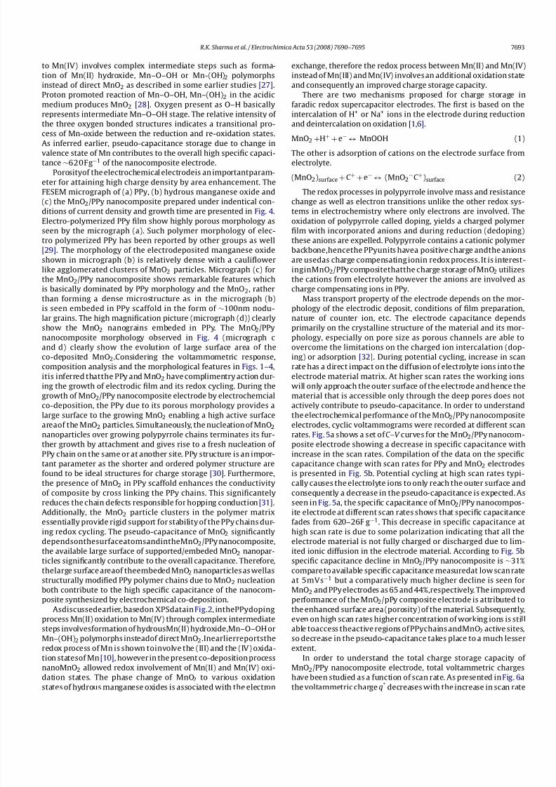
is presented in Fig. 5b. Potential cycling at high scan rates typi-
cally causes the electrolyte ions to only reach the outer surface and
consequently a decrease in the pseudo-capacitance is expected. As
seen in Fig. 5a, the specific capacitance of MnO2/PPy nanocompos-
ite electrode at different scan rates shows that specific capacitance
fades from 620–26F g−1. This decrease in specific capacitance at
high scan rate is due to some polarization indicating that all the
electrode material is not fully charged or discharged due to lim-
ited ionic diffusion in the electrode material. According to Fig. 5bspecific capacitance decline in MnO2/PPy nanocomposite is ∼31%
compare to available specific capacitance measuredat low scan rate
at 5mVs−1 but a comparatively much higher decline is seen for
MnO2 and PPy electrodes as 65 and 44%,respectively. The improved
performance of the MnO2/pPy composite electrode is attributed to
the enhanced surface area (porosity) of the material. Subsequently,
even on high scan rates higher concentration of working ions is still
able toaccess theactive regions of PPychains andMnO2 active sites,
so decrease in the pseudo-capacitance takes place to a much lesser
extent.
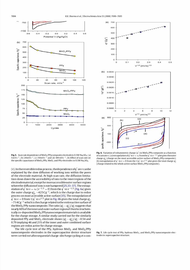
In order to understand the total charge storage capacity of
MnO2/PPy nanocomposite electrode, total voltammetric charges
have been studied as a function of scan rate. As presented in Fig. 6a
the voltammetric charge q*
decreases with the increase in scan rate
7/27/2019 MnO2 -Doped PPy Supercapaci.
http://slidepdf.com/reader/full/mno2-doped-ppy-supercapaci 5/6
7694 R.K. Sharma et al. / Electrochimica Acta 53 (2008) 7690–7695
Fig.5. Scanrate dependence of MnO2/PPycomposite electrodein 0.5M Na2SO4; (a)
5 mV s−1 , (b) 20mVs−1, (c) 50mVs−1 and (d) 100 mVs−1. (b) Effect of scan rate on
the specific capacitance of MnO2/PPy, MnO2 and PPy electrodes in 0.5M Na2SO4.
(v). In thereversibleredox process, thedependence of q* onv canbe
explained by the slow diffusion of working ions within the pores
of the electrode material. At high scan rate, the diffusion limita-
tion slows down the accessibility of ions to the innerregions of the
electrodematerial, except for moreaccessibleouter surface regions
wherethe diffusionof ions is not hampered [25,33–37]. The extrap-
olation of q* to v =∞ (v−
1/2 = 0) from the q* vs v−
1/2 (Fig. 6a) givesthe outer charge q∗
O, ∼425Cg−1, which is the charge due to redox
process on most accessible active surface [35]. The extrapolation of
q* to v = 0 from 1/q* vs v1/2 plot in Fig. 6b gives the total charge q∗T,
∼714Cg−1 which is thecharge related tothe entireactive surface of
the MnO2/PPy nanocomposite. The ratio (q∗T −
q∗O
)/q∗T
suggests that
nearly 60%of theinnerand outer surface regionof theelectrochem-
ically co-deposited MnO2/PPynanocompositematerials is available
for the charge storage. A similar study carried out for the similarly
deposited PPy and MnO2 electrode shows (q∗T −
q∗O
)/q∗T ∼
0.54 and
0.79 implying 46 and 21% of the inner and outer combined surface
regions are redox active for charge storage.
The life cycle test of the PPy, hydrous MnO2 and MnO2/PPy
nanocomposite electrodes in the supercapacitor device structure
were carried out aftersequential charge–discharge cycling at a con-
Fig. 6. Variation of voltammetric charge (q*) in MnO2/PPy composite as a function
of scanratev; (a)extrapolation of q* to v =∞ fromthe q* vsv−1/2 plot gives theouter
charge q∗O
(charge on the most accessible active surface of MnO2/PPy composite);
(b) extrapolation of q* to v = 0 from the 1/q* vs v1/2 plot gives the total charge q∗T
(charge related to the whole active surface MnO2/PPy composite).
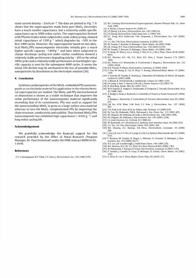
Fig. 7. Life cycle test of PPy, hydrous MnO2, and MnO2/PPy nanocomposite elec-
trodes in supercapacitor structure.
7/27/2019 MnO2 -Doped PPy Supercapaci.
http://slidepdf.com/reader/full/mno2-doped-ppy-supercapaci 6/6
R.K. Sharma et al. / Electrochimica Acta 53 (2008) 7690–7695 7695
stant current density ∼2mAcm−2. The data are plotted in Fig. 7. It
shows that the supercapacitor made from pure MnO2 electrodes
have a much smaller capacitance, but a relatively stable specific
capacitance up to 5000 redox cycles. The supercapacitor formed
with PPyelectrodes when subjectedto same redoxcycling, showed
initial capacitance of 120F g−1 which degrades by ∼50% in the
first 1000 cycles. However, the supercapacitor based on two iden-
tical MnO2/PPy nanocomposite electrodes initially give a muchhigher specific capacity ∼180Fg−1 and later when subjected to
charge–discharge cycling test under similar conditions showed a
relatively stable performance degrading only by∼10% in the initial
1000 cycles and a relatively stable performance at muchhigher spe-
cific capacity is seen for the subsequent 4000 cycles. It seems the
initial 10% decline may be attributed to the loss of unstable MnO2
nanoparticles by dissolution in the electrolyte solution [36].
4. Conclusion
Synthesis andproperties of the MnO2 embedded PPy nanocom-
posite as an electrode material for application in the electrochemi-
cal supercapacitor are studied. The MnO2 and PPy electrochemical
co-deposition is shown as a viable technique that improves the
redox performance of the nanocomposite material significantly
exceeding that of its constituents. PPy was used as support for
the nanocrystalline MnO2 to grow as a large surface area material
whereas in turn the MnO2 complemented PPy by improving the
chain structure, conductivity and stability. Thus formed MnO2/PPy
nanocomposite has exhibited high capacitance (∼620Cg−1) and
long redox cycling life.
Acknowledgement
We gratefully acknowledge the financial support for this
research provided by the Office of Naval Research (Program
Manager, Dr. Paul Armistead) under the ONR contract N00014-03-
1-0195.
References
[1] S. Sarangapani, B.V. Tilak, C.P. Chen, J. Electrochem. Soc. 143 (1996) 3791.
[2] B.E. Conway, Electrochemical Supercapacitors, Kluwer Plenum Pub. Co., NewYork, 1999.
[3] A. Burke, J. Power Sources 91 (2000) 37.[4] J.P. Zheng, T.R. Jow, J. Electrochem. Soc. 142 (1995) L6.[5] J.P. Zheng, Electrochem. Solid-State Lett. 2 (1999) 359.[6] S.C. Pang, M.A. Anderson, T.W. Chapman, J. Electrochem. Soc. 147 (2000)
444.[7] C.C. Hu, T.W. Tsou, Electrochem. Commun. 4 (2002) 105.[8] M. Toupin, T. Brousse, D. Belanger, Chem. Mater. 14 (2002) 3946.[9] J.K. Chang, W.T. Tsai, J. Electrochem. Soc. 150 (2003) A1333.
[10] M. Toupin, T. Brousse, D. Belanger, Chem. Mater. 16 (2004) 3184.[11] X. Dong, W. Shen, J. Gu, L. Xiong, Y. Zhu, H. Li, J. Shi, J. Phys. Chem. B110 (2006)
6015.[12] R.K. Sharma, H.S. Oh, Y.G. Shul, H.S. Kim, J. Power Sources 173 (2007)
1024.[13] R.E. Pinero, E.V. Khomenko, E. Frackowiak, F. Beguin, J. Electrochem. Soc. 152
(2005) A229.[14] K.R. Prasad, N. Miura, Electrochem. Commun. 6 (2004) 1004.[15] Z. Fan, M. Wang, K. Cui, H. Zhou, Y. Kunag, Diamond Relat. Mater. 15 (2006)
1478.[16] Y. Soneda, M. Toyoda, K. Hashiya, J. Yamashita, M. Kadoma, H. Hitori, M. Ingaki,
Carbon 41 (2003) 2680.[17] S. Biniak, B. Dzielendziak, J. Siedlewski, Carbon 33 (1995) 1255.[18] J.H. Jang, S. Han, T. Hyeon, E.M. Oh, J. Power Sources 123 (2003) 79.[19] B. Wessling, Synth. Met. 85 (1997) 1313.[20] M.D. Ingram,A. Pappin,F. Delaleande, D. Poupard, G. Terzulli, Electrochim. Acta
43 (1998) 1601.[21] A. Rudge,J. Davey, I. Raistrick, S. Gottsfeld, J.P. Feraris, J. Power Sources47 (1994)
89;A. Rudgea, I. Raistricka, S. Gottesfeld, J.P. Ferraris, Electrochim. Acta 39 (1994)273.
[22] J.M. Ko, H.W. Rhee, S.M. Park, C.Y. Kim, J. Electrochem. Soc. 137 (1990)905.
[23] Y.H. Park, K.W. Kim, W.H. Jo, Polym. Adv. Technol. 13 (2000) 670.[24] B.J. Tan, B.J. Klabunde, P.M.A. Sherwood, J. Am. Chem. Soc. 113 (1991) 855.[25] M. Chigane, M. Ishikawa, M. Izaki, J. Electrochem. Soc. 148 (2001) D96.[26] M. Chigane, M. Ishikawa, J. Electrochem. Soc. 147 (2000) 2246.[27] C.J. Lind, Environ. Sci. Technol. 22 (1988) 62.[28] M. Ramstedt, A.V. Shchukarev, S. Sjoberg, Surf. Interface Anal. 34 (2002) 632.[29] C.C. Hu, C.H. Chu, Electroanal. Chem. 503 (2001) 105.[30] R.K. Sharma, A.C. Rastogi, S.B. Desu, Electrochem. Commun. 10 (2008)
268.[31] J. Joo, J.K. Lee, S.Y. Yee, K.S. Jang, E.J. Oh, A.J. Epstein, Macromolecules33 (2000)
5131.[32] T. Brousse, M. Toupin, R. Dugas, L. Athouel, O. Crosnier, D. Belanger, J. Elec-
trochem. Soc. 153 (2006) A2171.[33] H.Y. Lee, J.B. Goodenough, J. Solid State Chem. 144 (1999) 220.
[34] R.K. Sharma, H.S. Oh, Y.G. Shul, H.S. Kim, Physica B 403 (2008) 1763.[35] M. Nakayama, T. Kanaya, R. Inoue, Electrochem. Commun. 9 (2007) 1154.[36] P. Soudan, J. Gaudet, D. Guay, D. Belanger, D. Schulz, Chem. Mater. 14 (2002)
1210.[37] Z. Zhou, N. Cai, Y. Zhou, Mater. Chem. Phys. 95 (20 05) 371.