Embed Size (px)
Citation preview
MARMARAY PROJECT CONTRACT CR1
MARMARAY PROJECT CONTRACT CR1 Title : DMD85DP114_BASIC DESIGN PASS. CAR
MAINT.ELECT.WS CONCRETE (HALKALI) DSI
Project Reference : MMY10-SYS-D3BD-DSI-80D-R-24003-A2 Internal Status : Approved Date : March. 30th, 2010
File name: MMY10-SYS-D3BD-DSI-80D-R-24003-A2 Pile Supporting of Tracks, Slab, Strip and Mat Foundations Report Page : 3 / 38
CONTENT
1 GEOTECHNICAL ASSESSMENT OF HALKALI PCME........................................................................................5 1.1 SITE CLASS (BEFORE ANY IMPROVEMENT) .................................................................................. 5 1.2 EXPECTED LOADS AND AVERAGE NATURAL ELEVATION .............................................................. 5 1.3 BEARING CAPACITY OF FOUNDATION SOIL.................................................................................. 6
1.3.1 STRIP FOOTINGS PLACED ON NATURAL SOIL FOUNDATION ................................................................6 1.3.1.1 Bearing Capacity...................................................................................................................6 1.3.1.2 Settlement Calculations ........................................................................................................7
1.3.2 SLABS FREELY PLACED ON THE NATURAL SOIL .................................................................................8 1.3.2.1 Bearing Capacity...................................................................................................................9 1.3.2.2 Settlement Calculation..........................................................................................................9
1.3.3 MAT FOUNDATION AT OFFICE SECTIONS ..........................................................................................11 1.3.3.1 Bearing Capacity.................................................................................................................11 1.3.3.2 Settlement Calculation........................................................................................................12
1.3.4 TURNTABLE FOUNDATION...............................................................................................................14 1.3.4.1 Bearing capacity .................................................................................................................14 1.3.4.2 Settlement...........................................................................................................................15
2 PILE FOUNDATIONS ..................................................................................................................................16 2.1 PILE FOUNDATION UNDER SLAB + TRACK+ STRIP FOUNDATION SECTIONS ................................ 16
2.1.1 FINAL DOWN DRAG FORCE .............................................................................................................16 2.1.2 RATE OF DEVELOPMENT OF DOWN DRAG FORCE WITHIN 100 YEARS ...............................................17 2.1.3 END BEARING PILE CAPACITY.........................................................................................................17 2.1.4 SKIN FRICTION CAPACITY TROUGH 2.0 M OF SOCKET LENGTH IN DISINTEGRATED MARL LAYER ........18 2.1.5 ULTIMATE TOTAL PILE CAPACITY ....................................................................................................18 2.1.6 PILE SPACE UNDER WORKSHOP AXES BETWEEN 1 ~ 23, B ~ D........................................................18 2.1.7 GROUP EFFECT FACTOR ON PILE CAPACITY ...................................................................................19 2.1.8 SAFETY FACTORS OF BEARING CAPACITY OF PILE...........................................................................19 2.1.9 PILE TOTAL SETTLEMENT ...............................................................................................................19 2.1.10 NEGLECTED POSITIVE EFFECT OF ADHESION FORCE IN THE LAST METERS OF CLAY LAYER ON ULTIMATE PILE CAPACITY ..............................................................................................................................20
3 UNDER LATHE...........................................................................................................................................22 3.1 LOADS..................................................................................................................................... 22 3.2 PILE CAPACITY CALCULATION................................................................................................... 22 3.3 PILE NUMBER OF POOL SECTION OF UNDER LATHE..................................................................... 22 3.4 PILE SPACE ............................................................................................................................. 22 3.5 GROUP EFFECT ON PILE CAPACITY............................................................................................ 23 3.6 SLAB SECTIONS TOGETHER WITH STRIP FOUNDATION OF UNDER LATHE ...................................... 23 4 PILE SUPPORTING OF OFFICE SECTION ....................................................................................................24
4.1 1 – 7 AXIS................................................................................................................................ 24 4.1.1 ULTIMATE AND SAFE PILE CAPACITY...............................................................................................24 4.1.2 PILE NUMBER AND GROUP EFFECT FACTOR....................................................................................24
4.2 7 – 15 AXIS.............................................................................................................................. 25 4.2.1 ULTIMATE AND SAFE PILE CAPACITY...............................................................................................25 4.2.2 PILE NUMBER AND GROUP EFFECT.................................................................................................25
4.3 15 – 23 AXIS............................................................................................................................ 25 4.3.1 ULTIMATE AND SAFE PILE CAPACITIES ..........................................................................................25
MARMARAY PROJECT CONTRACT CR1
MARMARAY PROJECT CONTRACT CR1 Title : DMD85DP114_BASIC DESIGN PASS. CAR
MAINT.ELECT.WS CONCRETE (HALKALI) DSI
Project Reference : MMY10-SYS-D3BD-DSI-80D-R-24003-A2 Internal Status : Approved Date : March. 30th, 2010
File name: MMY10-SYS-D3BD-DSI-80D-R-24003-A2 Pile Supporting of Tracks, Slab, Strip and Mat Foundations Report Page : 4 / 38
4.3.2 PILE NUMBER AND GROUP EFFECT.................................................................................................26 5 SOIL LIQUEFACTION .................................................................................................................................27
5.1 THEORETICAL KNOWLEDGE ON SOIL LIQUEFACTION.................................................................. 27 5.2 THEORETICAL KNOWLEDGE ON SOIL LIQUEFACTION.................................................................. 33
5.2.1 SOIL LIQUEFACTION ANALYSES FOR VARIOUS BOREHOLES AT PCME ..............................................33 6 GENERAL CONCLUSIONS ..........................................................................................................................38
MARMARAY PROJECT CONTRACT CR1
MARMARAY PROJECT CONTRACT CR1 Title : DMD85DP114_BASIC DESIGN PASS. CAR
MAINT.ELECT.WS CONCRETE (HALKALI) DSI
Project Reference : MMY10-SYS-D3BD-DSI-80D-R-24003-A2 Internal Status : Approved Date : March. 30th, 2010
File name: MMY10-SYS-D3BD-DSI-80D-R-24003-A2 Pile Supporting of Tracks, Slab, Strip and Mat Foundations Report Page : 5 / 38
1 GEOTECHNICAL ASSESSMENT OF HALKALI PCME The dimensions of building are 31.1 * 120.2 m and in the first trial, strip footings and slabs will be founded on the natural clay and sandy layers. The soil profile under the area can be represented by H29, 35, 36, 38, 39, though their location of H29, H35 and H39 are a little bit outside of building borders.
1.1 SITE CLASS (BEFORE ANY IMPROVEMENT) 2. a) According to IBC 2006
The weighted average of SPT is calculated within the first 100 feet (30.48m) starting from the bottom of strip footing of 5.4 CD as follows; Total thickness of compressible layers = 5.40 – (-20.80) = 26.20 m Min. average of SPT value at boreholes H35 and H38 = 8 SPT value in the marl or lime stone = 100 Considered depth in the limestone = 30.48 – 25.60 = 4.88 m SPT N = 30.48 / [26.2/8 + 4.28 /100] = 9.2 N ≤15 Site Class E b) According to Specification – 2007 Turkish Earthquake Research Institute The average SPT values within the clay layers at boreholes H35, 36, 38 and 39 are 7.6, 7.8, 6.8 and 8.2; can be accepted for overall site is less than 8 Site Group D N < 10 loose Sand
N < 8 Soft Clay, silty Clay For the total thickness of h1 > 10.0 for local soil class Z4 Local Soil Class = Z4 Ta = 0.20 s, Tb = 0.90s
1.2 EXPECTED LOADS AND AVERAGE NATURAL ELEVATION Administration building includes subbasement, at axes between 8 and 23 which its width and depth are 8.85 m, and 3.4 m; the two strip footings width are 2.50 m and 1.3 m, their depth are 1.1m, respectively. The rail elevation is +6.00 CD, consequently, the bottom elevation of strip footing and mat foundation at subbasement are 4.9 m and +2.6 CD. The slab width is considerably large, about 24 m, and the stress can be assumed to be equally distribute to whole width in a range of 40 kPa, cancelling multiplied dynamic factor 1.3. The elevation of slab bottom can calculated as using fictive depth (total cross section area / slab width). The natural elevations are determined in the 21 points and the average is calculated as +4.50CD. Therefore, fill load between +4.5 CD average level and + 6.0 CD will be added to the strip footing (6.0 – 4.5) * 20 = 30 kPa. For slab, fill load to be added is only (5.6 – 4.5)*20 = 22 kPa.
MARMARAY PROJECT CONTRACT CR1
MARMARAY PROJECT CONTRACT CR1 Title : DMD85DP114_BASIC DESIGN PASS. CAR
MAINT.ELECT.WS CONCRETE (HALKALI) DSI
Project Reference : MMY10-SYS-D3BD-DSI-80D-R-24003-A2 Internal Status : Approved Date : March. 30th, 2010
File name: MMY10-SYS-D3BD-DSI-80D-R-24003-A2 Pile Supporting of Tracks, Slab, Strip and Mat Foundations Report Page : 6 / 38
1.3 BEARING CAPACITY OF FOUNDATION SOIL
1. In the first attempt, without any soil improvement, the structural loads are assumed to be supported by the structural columns; and columns loads will be transferred by strip footings to the natural soil foundation. Similarly, the slabs and mat foundations are assumed to be directly founded on the compressible clay and sand layers.
2. In the second attempt, all footings in various widths, shape and depths, and slabs are evaluated due to supporting of stone columns in various patterns.
1.3.1 Strip Footings Placed on Natural Soil Foundation
1.3.1.1 Bearing Capacity
Actually, the average level is +4.5, and base of strip is +4.90, therefore the strip foundation is placed on the granular compacted fill, but holding on safer side, the bearing capacity will be calculated due to below layers. But load coming from fill between 4.5 and 6.0 m (surrounding preparation level) will be added to the structural load. (20 * 1.5 = 30 kPa)
The base elevation of footings 6.00 – 1.10 = +4.90CD. Strip footings width (B) 2.5 and 1.3 m = 2.5 m The interested depth = φ0 = 0 → 0.5 B TAN (45+φ/2) = 1.25 m The interested levels range (in bearing capacity) =+4.90 ~ +3.65 CD Actual average level = +4.50 CD
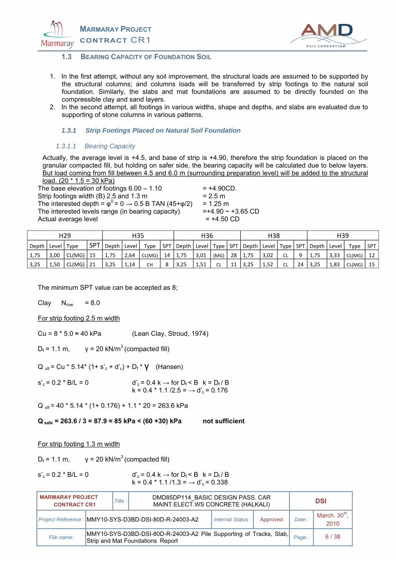
H29 H35 H36 H38 H39 Depth Level Type SPT Depth Level Type SPT Depth Level Type SPT Depth Level Type SPT Depth Level Type SPT
1,75 3,00 CL(MG) 15 1,75 2,64 CL(MG) 14 1,75 3,01 (MG) 28 1,75 3,02 CL 9 1,75 3,33 CL(MG) 12
3,25 1,50 CL(MG) 21 3,25 1,14 CH 8 3,25 1,51 CL 11 3,25 1,52 CL 24 3,25 1,83 CL(MG) 15 The minimum SPT value can be accepted as 8; Clay Nrow = 8.0 For strip footing 2.5 m width Cu = 8 * 5.0 ≈ 40 kPa (Lean Clay, Stroud, 1974) Df = 1.1 m, γ = 20 kN/m3 (compacted fill) Q ult = Cu * 5.14* (1+ s’c + d’c) + Df * γ (Hansen) s’c = 0.2 * B/L = 0 d’c = 0.4 k → for Df < B k = Df / B k = 0.4 * 1.1 /2.5 = → d’c = 0.176 Q ult = 40 * 5.14 * (1+ 0.176) + 1.1 * 20 = 263.6 kPa Q safe = 263.6 / 3 = 87.9 ≈ 85 kPa < (60 +30) kPa not sufficient For strip footing 1.3 m width Df = 1.1 m, γ = 20 kN/m3 (compacted fill) s’c = 0.2 * B/L = 0 d’c = 0.4 k → for Df < B k = Df / B k = 0.4 * 1.1 /1.3 = → d’c = 0.338
MARMARAY PROJECT CONTRACT CR1
MARMARAY PROJECT CONTRACT CR1 Title : DMD85DP114_BASIC DESIGN PASS. CAR
MAINT.ELECT.WS CONCRETE (HALKALI) DSI
Project Reference : MMY10-SYS-D3BD-DSI-80D-R-24003-A2 Internal Status : Approved Date : March. 30th, 2010
File name: MMY10-SYS-D3BD-DSI-80D-R-24003-A2 Pile Supporting of Tracks, Slab, Strip and Mat Foundations Report Page : 7 / 38
Q ult = 40 * 5.14 * (1+ 0.338) + 1.1 * 20 = 297.1 kPa Q safe = 297.1 / 3 = 99.0 ≈ 100 kPa > (60 +30) kPa sufficient
1.3.1.2 Settlement Calculations
Settlement calculation for B = 2.50 m The interested depth = 5 * B = 2.50 * 5 = 12.5 m Interested elevation range +4.9 – 12.5 = -7.60 CD In the related depth range, the average SPT values between +4.9 and – 7.60 CD are 11.3, 7.8, 9.3, 6.3 and 8.1 for boreholes H29, H29A, H35, H36, H38 and H39. The worst one is at H38 which its average value is only 6.3. The overall general average of site, in the same depths, can be accepted as 8.0 Consolidation settlement, under fill and structural load of 90 kPa (60 +30). SPTave = 8 Mcave = 8.0 * 0.5 = 4.00 MN/m2 → Mv = 1/Mc = 1 /4.0 = 0.250 m2 /MN H = layer thickness (effected) = 12.5 m But the first 0.4 is composed of compacted fill, so, in settlement calculation the compressible thickness will be taken 12.5 – 0.4 = 12.1 m бv = 60 +30 kPa = 0.090 MN/m2 ξ = average stress ratio within 5 * B, due to Bousinesq equation = 0.35 From fill load ∆Sc1= бv * H * Mv * ξ → 0.030 * 12.1 * 0.250 * 0.35 = 0.0318 m From structural load ∆Sc2= бv * H * Mv * ξ → 0.060 * 12.1 * 0.250 * 0.35 = 0.0635m Elastic settlement Timoshenko – Goodier,(1951) E’s = Mc = 8 * 0.5 = 4.0 MN/m2 → Es = E’s /0.6 = 4.0 /0.6 = 6.67 MN/m2 бv = 0.090 MN/m2 µ = 0.4 (Poison Ratio) , I1 =0.776, I2 = 0.111, Is = 0.813, Isr = 0.757 Df / B = 1.1 / 2.5 = 0.44→ If = 0.95 = From fill load ∆s1 = 0.0136 m From structural load ∆s2 = 0.0271 m Total settlement From fill load = 3.18 + 1.36 = 4.54 cm From structural load = 6.35 + 2.71 = 9.06 cm > 2.5 cm allowable limit for strip foundation. Settlement calculation for B = 1.3 m
MARMARAY PROJECT CONTRACT CR1
MARMARAY PROJECT CONTRACT CR1 Title : DMD85DP114_BASIC DESIGN PASS. CAR
MAINT.ELECT.WS CONCRETE (HALKALI) DSI
Project Reference : MMY10-SYS-D3BD-DSI-80D-R-24003-A2 Internal Status : Approved Date : March. 30th, 2010
File name: MMY10-SYS-D3BD-DSI-80D-R-24003-A2 Pile Supporting of Tracks, Slab, Strip and Mat Foundations Report Page : 8 / 38
The interested depth = 5 * B = 1.30 * 5 = 6.5 m Interested elevation range +4.9 – 6.5 = -1.60 CD The same soil average parameters, which are accepted in strip footing having 2.5 m width, will be used. From Fill load ∆Sc1 = бv1 * H * Mv * ξ (0.030) *(6.5-0.4)*0.250*0.35 = 0.0160 m From structural load ∆Sc2 = бv2 * H * Mv * ξ (0.060) *(6.5-0.4)*0.250*0.35 = 0.0320 m
Elastic settlement Es = 6,67 MN/m2 бv1 = 0.030 MN/m2 бv2= 0.060 MN/m2, I1 =0.776, I2 = 0.111, Is = 0.813, Isr = 0.757 Df / B = 1.1 / 2.5 = 0.44→ If = 0.95 = From fill load ∆s1 = 0.0050 m From structural load ∆s2 = 0.0100 m Total settlement From fill load = 2.1 cm From structural load = 4.2 cm > 2.5 cm allowable limit for strip foundation. Because of large total settlement under 90 kPa, which is completely out of allowable limits, the strip foundation shall not be directly founded on the compressible clay layers. Therefore, it is decided that the strip foundation will be supported by stone column.
1.3.2 Slabs Freely Placed on the Natural Soil
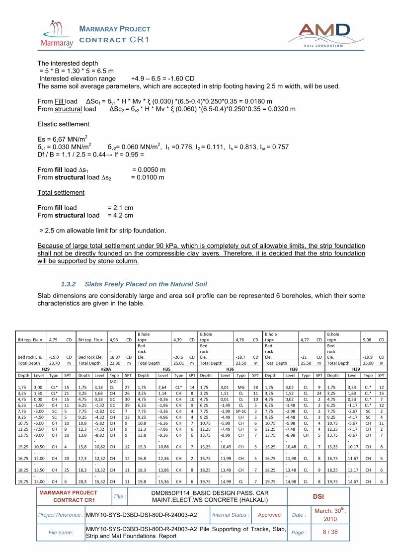
Slab dimensions are considerably large and area soil profile can be represented 6 boreholes, which their some characteristics are given in the table.
BH top. Ele.= 4,75 CD BH top. Ele.= 4,93 CD B.hole top= 4,39 CD
B.hole top= 4,76 CD
B.hole top= 4,77 CD
B.hole top= 5,08 CD
Bed rock Ele. ‐19,0 CD Bed rock Ele. ‐18,37 CD
Bed rock Ele. ‐20,6 CD
Bed rock Ele. ‐18,7 CD
Bed rock Ele. ‐21 CD
Bed rock Ele. ‐19,9 CD
Total Depth 23,70 m Total Depth 23,30 m Total Depth 25,01 m Total Depth 23,50 m Total Depth 25,50 m Total Depth 25,00 m H29 H29A H35 H36 H38 H39
Depth Level Type SPT Depth Level Type SPT Depth Level Type SPT Depth Level Type SPT Depth Level Type SPT Depth Level Type SPT
1,75 3,00 CL* 15 1,75 3,18 MG‐CL 27 1,75 2,64 CL* 14 1,75 3,01 MG 28 1,75 3,02 CL 9 1,75 3,33 CL* 12
3,25 1,50 CL* 21 3,25 1,68 CH 26 3,25 1,14 CH 8 3,25 1,51 CL 11 3,25 1,52 CL 24 3,25 1,83 CL* 15 4,75 0,00 CH 15 4,75 0,18 GC 30 4,75 ‐0,36 CH 10 4,75 0,01 CL 10 4,75 0,02 CL 2 4,75 0,33 CL* 7 6,25 ‐1,50 CH 11 6,25 ‐1,32 GC 39 6,25 ‐1,86 CH 9 6,25 ‐1,49 CL 5 6,25 ‐1,48 CL 2 6,25 ‐1,17 CL* 12 7,75 ‐3,00 SC 5 7,75 ‐2,82 GC 7 7,75 ‐3,36 CH 4 7,75 ‐2,99 SP‐SC 3 7,75 ‐2,98 CL 2 7,75 ‐2,67 SC 2 9,25 ‐4,50 SC 5 9,25 ‐4,32 CH 13 9,25 ‐4,86 CH 4 9,25 ‐4,49 CH 5 9,25 ‐4,48 CL 3 9,25 ‐4,17 SC 4 10,75 ‐6,00 CH 10 10,8 ‐5,82 CH 9 10,8 ‐6,36 CH 7 10,75 ‐5,99 CH 6 10,75 ‐5,98 CL 4 10,75 ‐5,67 CH 11 12,25 ‐7,50 CH 8 12,3 ‐7,32 CH 9 12,3 ‐7,86 CH 6 12,25 ‐7,49 CH 6 12,25 ‐7,48 CL 4 12,25 ‐7,17 CH 2 13,75 ‐9,00 CH 10 13,8 ‐8,82 CH 9 13,8 ‐9,36 CH 6 13,75 ‐8,99 CH 7 13,75 ‐8,98 CH 5 13,75 ‐8,67 CH 7
15,25 ‐10,50 CH 4 15,8
‐10,82 CH 12 15,3
‐10,86 CH 7 15,25
‐10,49 CH 5 15,25
‐10,48 CL 7 15,25
‐10,17 CH 8
16,75 ‐12,00 CH 20 17,3
‐12,32 CH 12 16,8
‐12,36 CH 2 16,75
‐11,99 CH 5 16,75
‐11,98 CL 8 16,75
‐11,67 CH 5
18,25 ‐13,50 CH 25 18,3
‐13,32 CH 11 18,3
‐13,86 CH 8 18,25
‐13,49 CH 7 18,25
‐13,48 CL 9 18,25
‐13,17 CH 6
19,75 ‐15,00 CH 6 20,3
‐15,32 CH 11 19,8
‐15,36 CH 6 19,75
‐14,99 CL 7 19,75
‐14,98 CL 8 19,75
‐14,67 CH 6
MARMARAY PROJECT CONTRACT CR1
MARMARAY PROJECT CONTRACT CR1 Title : DMD85DP114_BASIC DESIGN PASS. CAR
MAINT.ELECT.WS CONCRETE (HALKALI) DSI
Project Reference : MMY10-SYS-D3BD-DSI-80D-R-24003-A2 Internal Status : Approved Date : March. 30th, 2010
File name: MMY10-SYS-D3BD-DSI-80D-R-24003-A2 Pile Supporting of Tracks, Slab, Strip and Mat Foundations Report Page : 9 / 38
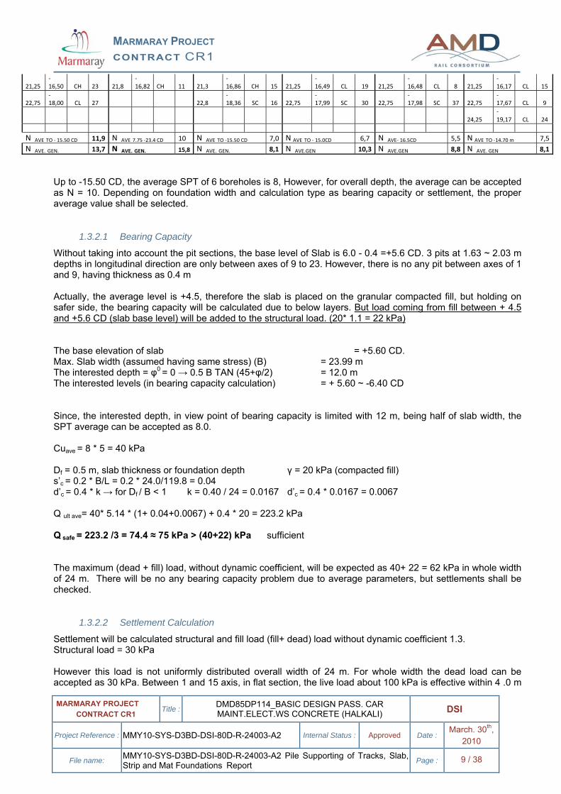
Up to -15.50 CD, the average SPT of 6 boreholes is 8, However, for overall depth, the average can be accepted as N = 10. Depending on foundation width and calculation type as bearing capacity or settlement, the proper average value shall be selected.
1.3.2.1 Bearing Capacity
Without taking into account the pit sections, the base level of Slab is 6.0 - 0.4 =+5.6 CD. 3 pits at 1.63 ~ 2.03 m depths in longitudinal direction are only between axes of 9 to 23. However, there is no any pit between axes of 1 and 9, having thickness as 0.4 m Actually, the average level is +4.5, therefore the slab is placed on the granular compacted fill, but holding on safer side, the bearing capacity will be calculated due to below layers. But load coming from fill between + 4.5 and +5.6 CD (slab base level) will be added to the structural load. (20* 1.1 = 22 kPa) The base elevation of slab = +5.60 CD. Max. Slab width (assumed having same stress) (B) = 23.99 m The interested depth = φ0 = 0 → 0.5 B TAN (45+φ/2) = 12.0 m The interested levels (in bearing capacity calculation) = + 5.60 ~ -6.40 CD Since, the interested depth, in view point of bearing capacity is limited with 12 m, being half of slab width, the SPT average can be accepted as 8.0. Cuave = 8 * 5 = 40 kPa Df = 0.5 m, slab thickness or foundation depth γ = 20 kPa (compacted fill) s’c = 0.2 * B/L = 0.2 * 24.0/119.8 = 0.04 d’c = 0.4 * k → for Df / B < 1 k = 0.40 / 24 = 0.0167 d’c = 0.4 * 0.0167 = 0.0067 Q ult ave= 40* 5.14 * (1+ 0.04+0.0067) + 0.4 * 20 = 223.2 kPa Q safe = 223.2 /3 = 74.4 ≈ 75 kPa > (40+22) kPa sufficient The maximum (dead + fill) load, without dynamic coefficient, will be expected as 40+ 22 = 62 kPa in whole width of 24 m. There will be no any bearing capacity problem due to average parameters, but settlements shall be checked.
1.3.2.2 Settlement Calculation
Settlement will be calculated structural and fill load (fill+ dead) load without dynamic coefficient 1.3. Structural load = 30 kPa However this load is not uniformly distributed overall width of 24 m. For whole width the dead load can be accepted as 30 kPa. Between 1 and 15 axis, in flat section, the live load about 100 kPa is effective within 4 .0 m
21,25 ‐16,50 CH 23 21,8
‐16,82 CH 11 21,3
‐16,86 CH 15 21,25
‐16,49 CL 19 21,25
‐16,48 CL 8 21,25
‐16,17 CL 15
22,75 ‐18,00 CL 27 22,8
‐18,36 SC 16 22,75
‐17,99 SC 30 22,75
‐17,98 SC 37 22,75
‐17,67 CL 9
24,25 ‐19,17 CL 24
N AVE TO ‐ 15.50 CD 11,9 N AVE 7.75 ‐23.4 CD 10 N AVE TO ‐15.50 CD 7,0 N AVE TO ‐ 15.0CD 6,7 N AVE‐ 16.5CD 5,5 N AVE TO ‐14.70 m 7,5N AVE. GEN. 13,7 N AVE. GEN. 15,8 N AVE. GEN. 8,1 N AVE.GEN 10,3 N AVE.GEN 8,8 N AVE. GEN 8,1
MARMARAY PROJECT CONTRACT CR1
MARMARAY PROJECT CONTRACT CR1 Title : DMD85DP114_BASIC DESIGN PASS. CAR
MAINT.ELECT.WS CONCRETE (HALKALI) DSI
Project Reference : MMY10-SYS-D3BD-DSI-80D-R-24003-A2 Internal Status : Approved Date : March. 30th, 2010
File name: MMY10-SYS-D3BD-DSI-80D-R-24003-A2 Pile Supporting of Tracks, Slab, Strip and Mat Foundations Report Page : 10 / 38
width, being accepted the longitudinal extension is 5 * 4 = 20 m. However between axis 15 to 23, under the pits, the width can be considered 3.0 m, which is subjected to 100 kPa live load In settlement calculation superimpose method will be applied. Fill load = (5.6 – 4.5) * 20 = 22 kPa. Since the effective depth will be 5 times of B, the stress will be applied through all compressible layers. The average SPT will be considered as 10. The lime stone or marl surface levels vary between -18.74 and 20.73 (H38), taking deepest level as -20.7CD, and the total layer thickness is 25.7 m, due to slab base level. Tough, it includes some sand layer; the total thickness is assumed to be consisted by only lean CLAY layers. Consolidation settlement under fill and structural dead load of 52 kPa Since, 30 kPa structural dead load and 22 kPa fill load will be exerted full width of 24 m, 52 kPa will be applied together. ξ = average stress ratio between + 5.0 to – 20.7 (25.70 m depth) levels at the centre. B/2 = B’=12.0 m, L’= 119.8/2 = 59.9 m z = 12.85 m (mid of compressible thickness) m = B’/z =0.93 n = L’/z = 59.9 /12.0 = 4.99 Average stress ratio trough 25.7 m depth (from +5.00 CD. Level) ξ = 0.78 Since, the slab width is effective to the lime stone layer, the average SPT N will be taken as 10. Mc = SPT (N) * 0.5 = 10.0 * 0.5 = 5.00 MN/m2 → Mv = 1/ Mc = 1 /5.00 = 0.200 m2 /MN H1 = layer thickness (effected) = 25.7 m, H2 = total thickness of only Clay layers is assumed 22.0 m бv = 30 + 22 = 52 kPa = 0.052 MN/m2 From fill → ∆Sc1 = ξ * бv * H2 * Mv → 0.78 * 0.022 * 22, 0 * 0.200 = 0.0755 m From structural →∆Sc2 = ξ * бv * H2 * Mv → 0.78 * 0.030 * 22, 0 * 0.200 = 0.1030 m Total consolidation settlement 0.179 m Elastic settlement The live and structural load effective overall width of 24 m is 30 kPa; however under the rail section the total load is reached to 100 kPa, in a width of 4.0 m. The effective length can be taken 5 times of 4.0 m. Therefore, settlement will be calculated by superposition method of two loads in different lengths and widths. Total thickness from bottom of slab (+ 5.00 CD) to bed rock is -20.70 m B = 24.0 m, L = 53 m (flat section) H/B = 25.7 / 24.0 = 1.07L / B = 4.99 Mc ave = (E’save) = 0.5 * 10.0 = 5.00 MN /m2 Es = E’s / 0.6 = 5.00/0.6 = 8.3 MN/m2 бv 1= 0.030 MN/m2 бv 2= 0.022 MN/m2
бv 3= The live load 100 kPa is assumed to be effective within 4.0 m width and 20 m length. But, since 30 kPa will be taken in over all width of 24 m, the net live load will be 70 kPa. I1 =0.305, I2 = 0.105, Is = 0.340, Isr = 0.317 L/B= 53/24 = 2.2 Df / B = 0.4 /24 = 0.0167 → If = 1.0,
MARMARAY PROJECT CONTRACT CR1
MARMARAY PROJECT CONTRACT CR1 Title : DMD85DP114_BASIC DESIGN PASS. CAR
MAINT.ELECT.WS CONCRETE (HALKALI) DSI
Project Reference : MMY10-SYS-D3BD-DSI-80D-R-24003-A2 Internal Status : Approved Date : March. 30th, 2010
File name: MMY10-SYS-D3BD-DSI-80D-R-24003-A2 Pile Supporting of Tracks, Slab, Strip and Mat Foundations Report Page : 11 / 38
22 kPa fill load ∆s1 = 0.03635 m 30 kPa structural load ∆s2 = 0.0462 m 70 kPa live load at rails I1 =0.816, I2 = 0.057, Is = 0.835, Isr = 0.777 L/B= 20/4 = 5 Df / B = 0.4 /4 = 0.10 → If = 1.0
∆s3 = 0.0473 m Total Settlement Settlement from fill load = 7.55 + 3.64 = 11.2 cm Settlement from structural load = 10.30 + 4.62 + 4.73 = 19.7 cm
1.3.3 Mat Foundation at office sections
1.3.3.1 Bearing Capacity
1– 8 axes Actually, the average level is +4.5, therefore the slab is placed on the granular compacted fill, but holding on safer side, the bearing capacity will be calculated due to below layers. But load coming from fill between 4.9 and 4.5 will be added to the structural load. (20* 0.4 = 8 kPa) Foundation depth Df = 1.1 m from + 6.00 CD. Foundation width and length B = 8.85 m L = 33.80 m Cu = 8 * 5 = 40 kPa Hansen General Bearing Capacity Qult = 5.14 * Cu (1 +S’c +D’c) + Df * γ S’c = 0.2 * B / L → 0.2 * 8.85 / 33.8 = 0.052 D’c = 0.4 * k → k = Df / B for Df / B < 1.0 0.4 * 1.1 / 8.85 = 0.05 Qult = 5.14 * 40 * (1 +0.052+ 0.05) + 1.1 * 18 = 246,4kPa Qall = 246,4 / 3 = 82 kPa ≈ 80 kPa > (60+8) kPa sufficient 8 - 15 axes Foundation depth Df = 4.3 m from + 6.00 CD. Since, the average existing level +4.5 CD, and between + 6.00 and +4.5 elevation will be filled, the base level 6.0 – 4.3 = +1.7 CD The fictive foundation depth to be taken in bearing capacity is 4.5 – 1.7 = 2.80 m, instead of 4.70 m Foundation width and length B = 9.45 m. actually there is no expansion joint between block B and C for total length of 88.30m, however, it can be practically assumed that the foundation length is L = 42.35 m Cu = 8 * 5 = 40 kPa Hansen General Bearing Capacity Qult = 5.14 * Cu (1 +S’c +D’c) + Df * γ S’c = 0.2 * B / L → 0.2 * 9,45 42.35 = 0.045 D’c = 0.4 * k → k = Df / B for Df / B < 1.0 0.4 * 2.8 / 9.45 = 0.119 Qult = 5.14 * 40 * (1 + 0.045 + 0.086) + 2.8 * 18 Qall = 289.7 /3 = 96.5 kPa ≈ 90 kPa > 95 kPa sufficient 15 - 23 axes Foundation depth Df = 4.3 m from + 6.00 CD. Since, the average level +4.5 CD, and the base level 6.0 – 4.3 = +1.7 CD The fictive foundation depth to be taken in bearing capacity is 4.5 – 1.7 = 2.8 m, instead of 4.3 m
MARMARAY PROJECT CONTRACT CR1
MARMARAY PROJECT CONTRACT CR1 Title : DMD85DP114_BASIC DESIGN PASS. CAR
MAINT.ELECT.WS CONCRETE (HALKALI) DSI
Project Reference : MMY10-SYS-D3BD-DSI-80D-R-24003-A2 Internal Status : Approved Date : March. 30th, 2010
File name: MMY10-SYS-D3BD-DSI-80D-R-24003-A2 Pile Supporting of Tracks, Slab, Strip and Mat Foundations Report Page : 12 / 38
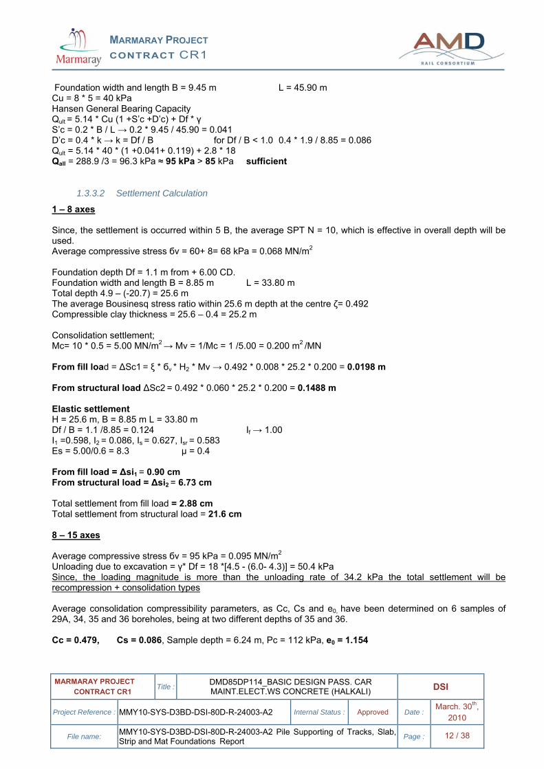
Foundation width and length B = 9.45 m L = 45.90 m Cu = 8 * 5 = 40 kPa Hansen General Bearing Capacity Qult = 5.14 * Cu (1 +S’c +D’c) + Df * γ S’c = 0.2 * B / L → 0.2 * 9.45 / 45.90 = 0.041 D’c = 0.4 * k → k = Df / B for Df / B < 1.0 0.4 * 1.9 / 8.85 = 0.086 Qult = 5.14 * 40 * (1 +0.041+ 0.119) + 2.8 * 18 Qall = 288.9 /3 = 96.3 kPa ≈ 95 kPa > 85 kPa sufficient
1.3.3.2 Settlement Calculation
1 – 8 axes Since, the settlement is occurred within 5 B, the average SPT N = 10, which is effective in overall depth will be used. Average compressive stress бv = 60+ 8= 68 kPa = 0.068 MN/m2 Foundation depth Df = 1.1 m from + 6.00 CD. Foundation width and length B = 8.85 m L = 33.80 m Total depth 4.9 – (-20.7) = 25.6 m The average Bousinesq stress ratio within 25.6 m depth at the centre ζ= 0.492 Compressible clay thickness = 25.6 – 0.4 = 25.2 m Consolidation settlement; Mc= 10 * 0.5 = 5.00 MN/m2 → Mv = 1/Mc = 1 /5.00 = 0.200 m2 /MN From fill load = ∆Sc1 = ξ * бv * H2 * Mv → 0.492 * 0.008 * 25.2 * 0.200 = 0.0198 m From structural load ∆Sc2 = 0.492 * 0.060 * 25.2 * 0.200 = 0.1488 m Elastic settlement H = 25.6 m, B = 8.85 m L = 33.80 m Df / B = 1.1 /8.85 = 0.124 If → 1.00 I1 =0.598, I2 = 0.086, Is = 0.627, Isr = 0.583 Es = 5.00/0.6 = 8.3 µ = 0.4 From fill load = ∆si1 = 0.90 cm From structural load = ∆si2 = 6.73 cm Total settlement from fill load = 2.88 cm Total settlement from structural load = 21.6 cm 8 – 15 axes Average compressive stress бv = 95 kPa = 0.095 MN/m2 Unloading due to excavation = γ* Df = 18 *[4.5 - (6.0- 4.3)] = 50.4 kPa Since, the loading magnitude is more than the unloading rate of 34.2 kPa the total settlement will be recompression + consolidation types Average consolidation compressibility parameters, as Cc, Cs and e0, have been determined on 6 samples of 29A, 34, 35 and 36 boreholes, being at two different depths of 35 and 36. Cc = 0.479, Cs = 0.086, Sample depth = 6.24 m, Pc = 112 kPa, e0 = 1.154
MARMARAY PROJECT CONTRACT CR1
MARMARAY PROJECT CONTRACT CR1 Title : DMD85DP114_BASIC DESIGN PASS. CAR
MAINT.ELECT.WS CONCRETE (HALKALI) DSI
Project Reference : MMY10-SYS-D3BD-DSI-80D-R-24003-A2 Internal Status : Approved Date : March. 30th, 2010
File name: MMY10-SYS-D3BD-DSI-80D-R-24003-A2 Pile Supporting of Tracks, Slab, Strip and Mat Foundations Report Page : 13 / 38
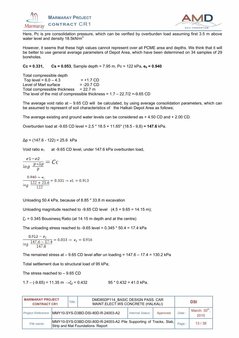
Here, Pc is pre consolidation pressure, which can be verified by overburden load assuming first 3.5 m above water level and density 18.5kN/m3 However, it seems that these high values cannot represent over all PCME area and depths. We think that it will be better to use general average parameters of Depot Area, which have been determined on 34 samples of 29 boreholes. Cc = 0.331, Cs = 0.053, Sample depth = 7.95 m, Pc = 122 kPa, e0 = 0.940 Total compressible depth Top level = 6.0 – 4.3 = +1.7 CD Level of Marl surface = -20.7 CD Total compressible thickness = 22.7 m The level of the mid of compressible thickness = 1.7 – 22.7/2 =-9.65 CD The average void ratio at – 9.65 CD will be calculated, by using average consolidation parameters, which can be assumed to represent of soil characteristics of the Halkalı Depot Area as follows; The average existing and ground water levels can be considered as + 4.50 CD and + 2.00 CD. Overburden load at -9.65 CD level = 2,5 * 18.5 + 11.65* (18.5 - 9,8) ≈ 147.6 kPa. ∆p = (147.6 - 122) = 25.6 kPa Void ratio e1 at -9.65 CD level, under 147.6 kPa overburden load,
Unloading 50.4 kPa, because of 8.85 * 33.8 m excavation Unloading magnitude reached to -9.65 CD level (4.5 + 9.65 = 14.15 m); ζ1 = 0.345 Bousinesq Ratio (at 14.15 m depth and at the centre) The unloading stress reached to -9.65 level = 0.345 * 50.4 = 17.4 kPa
The remained stress at – 9.65 CD level after un loading = 147.6 – 17.4 = 130.2 kPa Total settlement due to structural load of 95 kPa; The stress reached to – 9.65 CD 1.7 – (-9.65) = 11.35 m →ζ2 = 0.432 95 * 0.432 = 41.0 kPa.
MARMARAY PROJECT CONTRACT CR1
MARMARAY PROJECT CONTRACT CR1 Title : DMD85DP114_BASIC DESIGN PASS. CAR
MAINT.ELECT.WS CONCRETE (HALKALI) DSI
Project Reference : MMY10-SYS-D3BD-DSI-80D-R-24003-A2 Internal Status : Approved Date : March. 30th, 2010
File name: MMY10-SYS-D3BD-DSI-80D-R-24003-A2 Pile Supporting of Tracks, Slab, Strip and Mat Foundations Report Page : 14 / 38
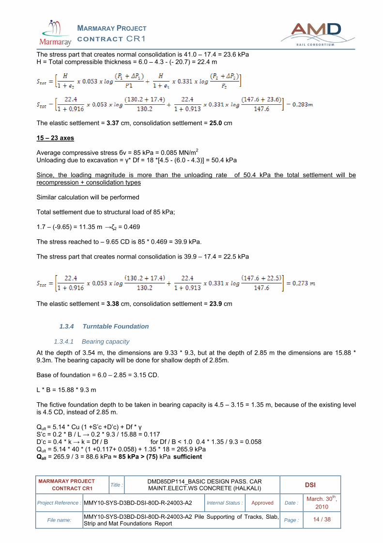
The stress part that creates normal consolidation is 41.0 – 17.4 = 23.6 kPa H = Total compressible thickness = 6.0 – 4.3 - (- 20.7) = 22.4 m
The elastic settlement = 3.37 cm, consolidation settlement = 25.0 cm 15 – 23 axes Average compressive stress бv = 85 kPa = 0.085 MN/m2 Unloading due to excavation = γ* Df = 18 *[4.5 - (6.0 - 4.3)] = 50.4 kPa Since, the loading magnitude is more than the unloading rate of 50.4 kPa the total settlement will be recompression + consolidation types Similar calculation will be performed Total settlement due to structural load of 85 kPa; 1.7 – (-9.65) = 11.35 m →ζ2 = 0.469 The stress reached to – 9.65 CD is 85 * 0.469 = 39.9 kPa. The stress part that creates normal consolidation is 39.9 – 17.4 = 22.5 kPa
The elastic settlement = 3.38 cm, consolidation settlement = 23.9 cm
1.3.4 Turntable Foundation
1.3.4.1 Bearing capacity
At the depth of 3.54 m, the dimensions are 9.33 * 9.3, but at the depth of 2.85 m the dimensions are 15.88 * 9.3m. The bearing capacity will be done for shallow depth of 2.85m. Base of foundation = 6.0 – 2.85 = 3.15 CD. L * B = 15.88 * 9.3 m The fictive foundation depth to be taken in bearing capacity is 4.5 – 3.15 = 1.35 m, because of the existing level is 4.5 CD, instead of 2.85 m. Qult = 5.14 * Cu (1 +S’c +D’c) + Df * γ S’c = 0.2 * B / L → 0.2 * 9.3 / 15.88 = 0.117 D’c = 0.4 * k → k = Df / B for Df / B < 1.0 0.4 * 1.35 / 9.3 = 0.058 Qult = 5.14 * 40 * (1 +0.117+ 0.058) + 1.35 * 18 = 265.9 kPa Qall = 265.9 / 3 = 88.6 kPa ≈ 85 kPa > (75) kPa sufficient
MARMARAY PROJECT CONTRACT CR1
MARMARAY PROJECT CONTRACT CR1 Title : DMD85DP114_BASIC DESIGN PASS. CAR
MAINT.ELECT.WS CONCRETE (HALKALI) DSI
Project Reference : MMY10-SYS-D3BD-DSI-80D-R-24003-A2 Internal Status : Approved Date : March. 30th, 2010
File name: MMY10-SYS-D3BD-DSI-80D-R-24003-A2 Pile Supporting of Tracks, Slab, Strip and Mat Foundations Report Page : 15 / 38
1.3.4.2 Settlement
Average compressive stress бv = 75 kPa = 0.075 MN/m2 Unloading due to excavation = γ* Df = 18 *[4.5 - (6.0- 2.85)] = 24.3 kPa Since, the loading magnitude is more than the unloading rate 24.3 kPa, the total settlement will be recompression + consolidation types The total interested depth 3.15 – (-20.7) = 23.85 m The mid of the interested dept = 23.85/2 = 11.93 m from 3.15 CD The level of mid = -8.78 CD The dead load at – 8.78 CD = 2.5 * 18.5 + 10.78 * (18.5 - 9.8) = 140 kPa 153.0 – 96.3 = 56.7 kPa
Unloading at - 8.78 CD, due to 24.3 kPa excavation Bousinesq ratio at z = 11.93 m depth and the centre of L * B = 15.88 * 9.3 m ζ = 0.333 Reached unloading stress at -8.78 CD = 0.333 * 24.3 = 8.1 kPa Structural load reached to – 8.78 CD = 0.333 * 75 = 25.0 kPa. Stress part apply as normal consolidation load = 25.0 – 8.1 = 16.9 kPa.
Void ratio at - 8.78 CD after excavation → 0.921 at rest H = 3.15 – (- 20.7) = 23.85 m
The elastic settlement = 1.70 cm, consolidation settlement = 20.35 cm
MARMARAY PROJECT CONTRACT CR1
MARMARAY PROJECT CONTRACT CR1 Title : DMD85DP114_BASIC DESIGN PASS. CAR
MAINT.ELECT.WS CONCRETE (HALKALI) DSI
Project Reference : MMY10-SYS-D3BD-DSI-80D-R-24003-A2 Internal Status : Approved Date : March. 30th, 2010
File name: MMY10-SYS-D3BD-DSI-80D-R-24003-A2 Pile Supporting of Tracks, Slab, Strip and Mat Foundations Report Page : 16 / 38
2 PILE FOUNDATIONS The slab +track sections and strip foundation are arranged as rigid system, therefore, the stress distribution considerably equalized for overall width of 24.95 m, disregarding office section. The average existing level of PCME is about +4.5CD, therefore it needs 1.1 m fill under the slab + track in full width of 25 m, in the first 50 m length between axis 1 and 10. However, at the other section between 10 and 23 axes, since the pits depth is about 1.5 m, fill will be placed under only slab sections. static and live loads of flat sections, the fill load will create a considerable settlement under overall area.
2.1 PILE FOUNDATION UNDER SLAB + TRACK+ STRIP FOUNDATION SECTIONS Since, the pile tips are founded on the marl layer, which is relatively rigid in comparison with the soft – medium clay overlain having 25.2 m thickness, piles and soil system will not be together settled and creates down drag forces on the piles. In pile capacity calculation the down drag force to be occurred at 100 years, which is progressed proportionally of consolidation rate (negative friction), will be taken in to account.
2.1.1 Final Down drag Force
This load will be applied under full slip condition between clay and pile. PN = PNFS.NR .NT + Pa formula (11.13) From “Pile Foundation Analysis and Design, H.G. Poulos and E.H. Davis” page 274. PNFS = final maximum down drag force if full pile soil slip occurs NR = correction factor for cases in which full slip does not occur. NT = correction factor for effects of delayed installation Pa = axial force in pile at top of consolidating layer - PROJECT working load (1300 kN) PNFS = π*D*L *[C’ae+Ks tanφ’a (γ*L/2+q)] formula (11.15) For D = 0.8 m pile diameter C’ae = C’a + Po Ks tanφ’a formula (11.10) Since there is no any cohesionless layer naturally placed on the clay layer, C’ae is equal zero. q = effective stress on top of clay layer = 1.1 * 20 = 22 kPa Clay, drained internal friction angle due to PI = 30 → 26 0 Clay horizontal earth pressure coefficient = Ks = Ko = 1 – sin 260 = 0.562 PNFS = π * 0.8 * 25.2 * [0.526*TAN 260 [(18.5*2.5+ (18.5-9.8)*(22.7)] / 2 + 22)] = 2338 kN NR = for D = 0.8 m L/D = 31.5, →γ* L/q = 243.7/22 = 11→ C’a/q = 0/22 = 0 by making interpolation between figure 11.5 and 11.6 which are prepared for Ks * tanφ = 0.2 and 0.4 (for our project Ks * tanφ’a = 0.562*0.488 = 0.275), →NR = 0.72 NT = any delay of pile installation up to 5 years, after application of fill load, does not effect on final down drag force Nt = 1.0 for one drainage way → from figure 11.8 T 0 = Cv * to/L2 → Cv = 2.60 m2 / year, L = 25.2 m, for 5 years, →0.0205→ NT = 1.0 PN1 = 2338* 0.72 *1.0 + 1300 = 1683+1200 = 2911 kN Down drag Force by fill layer composed of Sandy Gravel in a thickness of 1.1 m. Sandy Gravel →φ = 350 ¾* 350 = 260 → Ks * tanφ = 0.574* tan260 = 0.280 σv = at top of clay = 1.1* 20 = 22 kPa.
MARMARAY PROJECT CONTRACT CR1
MARMARAY PROJECT CONTRACT CR1 Title : DMD85DP114_BASIC DESIGN PASS. CAR
MAINT.ELECT.WS CONCRETE (HALKALI) DSI
Project Reference : MMY10-SYS-D3BD-DSI-80D-R-24003-A2 Internal Status : Approved Date : March. 30th, 2010
File name: MMY10-SYS-D3BD-DSI-80D-R-24003-A2 Pile Supporting of Tracks, Slab, Strip and Mat Foundations Report Page : 17 / 38
D = 0.8 Π * 0.8 * [22/2 * 1.1] * 0.280 = 8.5 kN Total final down drag force 2911,3+ 8.5 ≈ 2920 kN (297.7tons)
2.1.2 Rate of Development of Down Drag Force within 100 Years
Since, the down drag force is developed proportionally of completion of consolidation; the ultimate down drag force will be occurred after completely completion of consolidation. In calculation of down drag force development, one way drainage is assumed since the bottom layer consists of marl which can be considered impermeable, and used figure 11.11. Let us re calculate for 100 years later Tv = 2.6* 100/25.22 = 0.409 → for average of two curves for full slip and no slip UN = 0.70 (primer consolidation completion ratio) Pt = 0.70*(2920 – 1300) + 1300 = 2434 kN
2.1.3 End Bearing Pile Capacity
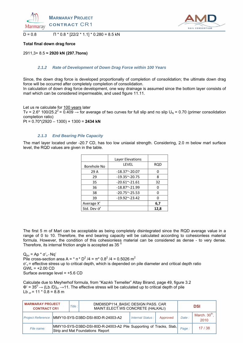
The marl layer located under -20.7 CD, has too low uniaxial strength. Considering, 2.0 m below marl surface level, the RQD values are given in the table.
Layer Elevations
Borehole No LEVEL RQD
29 A ‐18.37~‐20.07 0 29 ‐19.35~‐20.75 8 35 ‐20.61~‐21.61 32 36 ‐18.87~‐21.99 0 38 ‐20.75~‐25.53 0 39 ‐19.92~‐23.42 0
Average X’ 6,7 Std. Dev σ' 12,8
The first 5 m of Marl can be acceptable as being completely disintegrated since the RQD average value in a range of 0 to 10. Therefore, the end bearing capacity will be calculated according to cohesionless material formula. However, the condition of this cohesionless material can be considered as dense - to very dense. Therefore, its internal friction angle is accepted as 35 0 Qpu = Ap * σ’v * Nq’ Pile cross-section area A = * п * D2 /4 = π* 0.82 /4 = 0.5026 m2 σ’v = effective stress up to critical depth, which is depended on pile diameter and critical depth ratio GWL = +2.00 CD Surface average level = +5.6 CD Calculate due to Meyherhof formula, from “Kazıklı Temeller” Altay Birand, page 49, figure 3.2 Φ’ = 350 → (Lb /D)cr →11. The effective stress will be calculated up to critical depth of pile Lb cr = 11 * 0.8 = 8.8 m
MARMARAY PROJECT CONTRACT CR1
MARMARAY PROJECT CONTRACT CR1 Title : DMD85DP114_BASIC DESIGN PASS. CAR
MAINT.ELECT.WS CONCRETE (HALKALI) DSI
Project Reference : MMY10-SYS-D3BD-DSI-80D-R-24003-A2 Internal Status : Approved Date : March. 30th, 2010
File name: MMY10-SYS-D3BD-DSI-80D-R-24003-A2 Pile Supporting of Tracks, Slab, Strip and Mat Foundations Report Page : 18 / 38
σ’v = (5.6 - 2.0)*18.5 + (8.8 - 3.6) (18.5 - 9.8) = 111.84 kPa figure 3.3 page 50 for Φ’ = 350 → Nq’ =135 Qpu = 0.5026 * 111.84 * 135 = 7579 kN
2.1.4 Skin Friction Capacity Trough 2.0 m of Socket Length in Disintegrated Marl Layer
Since, the marl layer is completely disintegrated within 5.0 m, the friction force will be calculated due to friction force in granular layer. Qs = L2* π* D * fs
fs = K* σv’ * tan
k = k0 ~ 1.4 *k0 (for bored pile, Meyerhof,1976) k0 = 0.7 (NAVFAC,1988) σ’v = effective stress, that is increased up to critical depth for φ= 35 Lc/ D = 11 Lc = 8.8 m 8.8 * (18.5-9.8) = 76.56 kPa
Friction angle between concrete and marl = 3 /4 φ (NAVFAC,1988), (0.9 ~ 1.0) φ (ASCE,1993)
Qs = 2.0 * π* 0.8 * 76.56 * 0.7 * TAN (0.9 * 35) = 165 kN
2.1.5 Ultimate Total Pile Capacity
Qu + Qs = 7579 + 165 = 7744 kN
2.1.6 Pile Space under Workshop Axes between 1 ~ 23, B ~ D
The weighted average stress (due to their widths of each characteristics part of strip, track and slab) of overall width and length 24.9 is 63 kPa. After re evaluation statically, pile pattern may be arranged again. Total width = 24.90 m Total length = 120.90 m Total Area = 24.9 * 120.90 = 3010.41 m2 Total load = 63 kPa * 3010.41 = 189656 kN Minimum pile number 189656 / 1300 ≈ 146
Due to drawings prepared based on final Static study, the pile number is 165, which can be acceptable as convenient.
MARMARAY PROJECT CONTRACT CR1
MARMARAY PROJECT CONTRACT CR1 Title : DMD85DP114_BASIC DESIGN PASS. CAR
MAINT.ELECT.WS CONCRETE (HALKALI) DSI
Project Reference : MMY10-SYS-D3BD-DSI-80D-R-24003-A2 Internal Status : Approved Date : March. 30th, 2010
File name: MMY10-SYS-D3BD-DSI-80D-R-24003-A2 Pile Supporting of Tracks, Slab, Strip and Mat Foundations Report Page : 19 / 38
.
2.1.7 Group Effect Factor on Pile Capacity
For boring pile, the group factor which effects adversely ultimate pile capacity due to space length and diameter of piles, will be calculated according to “Pile Foundation Design and Design”H.G.Poulos, page 33, figure 3.19, from Whitaker,1957. Space S = 4.27 m → S/D = 4.27 / 0.8 = 5.33 Pile Length = 28.3 m → L/D = 28.3/0.8 =35.3 Group effect factor → ζ = 0.95
2.1.8 Safety Factors of Bearing Capacity of Pile
Ultimate pile capacity 7744 kN will be reduced due to group effect factor of 0.95 7744 * 0.95 = 7357 kN Due to 100 years down draw force 7357/ 2434 = 3.02 Due to ultimate force 7357/ 2920 = 2.52
2.1.9 Pile Total Settlement
ρFS = axial movement if pile full pile – soil slip occur QR = correction factor for cases in which full slip does not occur = 0.95 QT =correction factor for effects of delayed installation = 1.0 Pa = axial project force on pile at top of consolidation layer = 1300 kN L1 = Pile length in total clay layer = 25.2 m L 2 = Pile length together with upper granular fill layer = 26.3 m L3 = Pile length in marl = 2.0 m L = Total pile length = 25.2 + 1.1 + 2.0 = 28.3 m Ep = pile elasticity modulus = 32000 MN/m2 Ap = cross section area of pile = 0.5026 m2 Ra = area ratio, for filled cross section = 1.0 For C’ae/q = 0/22= 0 and γ*L /q = 11, by using figures 11.14 and 11.15→ QR = 0.95
γ * L1 = 2.5 * 18.5 + 22.7 * (18.5-9.8) = 243.7 kPa
MARMARAY PROJECT CONTRACT CR1
MARMARAY PROJECT CONTRACT CR1 Title : DMD85DP114_BASIC DESIGN PASS. CAR
MAINT.ELECT.WS CONCRETE (HALKALI) DSI
Project Reference : MMY10-SYS-D3BD-DSI-80D-R-24003-A2 Internal Status : Approved Date : March. 30th, 2010
File name: MMY10-SYS-D3BD-DSI-80D-R-24003-A2 Pile Supporting of Tracks, Slab, Strip and Mat Foundations Report Page : 20 / 38
Pile total settlement = 0.0037 m = 0.37 cm
2.1.10 Neglected Positive Effect of Adhesion Force in the Last Meters of Clay Layer on Ultimate Pile Capacity
The positive total adhesion or friction force on the surface of pile which is deployed in pile capacity calculation, under the condition of no settlement difference or less than 0.6 inch between Pile and surrounding Soil, has been neglected in our project condition, since the neutral axis can be placed very close to marl surface elevation. The positive adhesion force can be calculated, as follows; σ’v * tan (0.9 * φ) * Ko * L1 * π * D for φ = 260 →Lc / D = 5 Lc = 4.0 m σ’v = (4.5 - 2.0 ) * 18.5 + ( 4.0 - 2.5) (18.5 - 9.8) = 59.3 kPa L = Pile length under the neutral (equivalent) axis, in where the positive skin friction is created. But, before positive force putting in to calculation, this length must be correctly estimated. D = 0.8 m However, the neutral axis may be over Marl surface, having 3 – 5 m, which can create positive adhesion force as follows; Let us 5.0 m positive length Ko = 1- sin 26 = 0.526 59.3 * tan (0.9 * 26) * 0.562 * 5.0 * π * 0.8 = 181 kN This positive force, calculated here, is not added to the total pile capacity since the pile safety factor, without this contribution, is greater than 3.0.
MARMARAY PROJECT CONTRACT CR1
MARMARAY PROJECT CONTRACT CR1 Title : DMD85DP114_BASIC DESIGN PASS. CAR
MAINT.ELECT.WS CONCRETE (HALKALI) DSI
Project Reference : MMY10-SYS-D3BD-DSI-80D-R-24003-A2 Internal Status : Approved Date : March. 30th, 2010
File name: MMY10-SYS-D3BD-DSI-80D-R-24003-A2 Pile Supporting of Tracks, Slab, Strip and Mat Foundations Report Page : 21 / 38
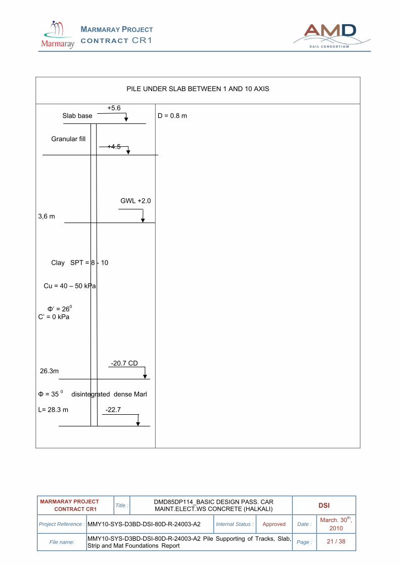
PILE UNDER SLAB BETWEEN 1 AND 10 AXIS
+5.6 Slab base Granular fill +4.5 GWL +2.0 3,6 m Clay SPT = 8 - 10 Cu = 40 – 50 kPa Φ’ = 260
C’ = 0 kPa -20.7 CD 26.3m Φ = 35 0 disintegrated dense Marl L= 28.3 m -22.7
D = 0.8 m
MARMARAY PROJECT CONTRACT CR1
MARMARAY PROJECT CONTRACT CR1 Title : DMD85DP114_BASIC DESIGN PASS. CAR
MAINT.ELECT.WS CONCRETE (HALKALI) DSI
Project Reference : MMY10-SYS-D3BD-DSI-80D-R-24003-A2 Internal Status : Approved Date : March. 30th, 2010
File name: MMY10-SYS-D3BD-DSI-80D-R-24003-A2 Pile Supporting of Tracks, Slab, Strip and Mat Foundations Report Page : 22 / 38
3 UNDER LATHE
3.1 LOADS It is located between 17- 23 and A - B axes. The base elevation of foundation is 6 .00 – 2.85 =+3.15 CD. The dimensions of pool section are 15.88 * 9.3 m, having as 75 kPa. Since, the bottom of the foundation is deeper than the average existing elevation of +4.5 CD, there will be no any load and negative friction force on piles. The total load on the mat foundation of pool is 75 * 15.83 * 9.3 = 11041 kPa. Since the base elevation is less than the average existing level of + 4.5CD, there will be no any fill load. Therefore, in pile capacity calculation, the down drag force will not be taken into account.
3.2 PILE CAPACITY CALCULATION Pile diameter = D = 0.6 m The total Clay layer thickness is 3.15 – (-20.7) = 23.85 m Embedded length in to marl layer = 2.00 m Total pile length = 25.85 m Since there is no any down drag force, the surface adhesion force on pile will be added to the total pile capacity. Qult = Qs + Qpu Pile cross section area A = * п * D2 /4 = π* 0.62 /4 = 0.28274m2 σ’v = effective stress up to critical depth, which is depended on pile diameter and critical depth ratio GWL = +2.00 CD Calculate due to Meyherhof formula, from “Kazıklı Temeller” Altay Birand, page 49, figure 3.2 Φ’ = 350 → (Lb /D)cr →11. The effective stress will be calculated up to critical depth of pile Lb cr = 11 * 0.6 = 6.6 m σ’v = (3.15 - 2.0)*18.5 + (6.6 – 1.15) (18.5 - 9.8) = 68.69 kPa figure 3.3 page 50 for Φ’ = 350 → Nq’ =135 Qpu = Ap * σ’v * Nq’ Qpu = 0.28274 * 68.69 * 135 = 2622 Qs = L* π* D* Cu * fs Cu = 50 kPa for SPT = 10 fs = adhesion ratio for Cu = 50 kPa→ fs = 0.75 Qs = 23.85 * π* 0.6* 50 * 0.75 = 1686 kPa Qult = 2622+1686 = 4308 Safe pile capacity = ζ* 4308 /3 = 1393 kN Group efficiency factor = 0.97
3.3 PILE NUMBER OF POOL SECTION OF UNDER LATHE Assuming uniform stress distribution, the minimum pile number, having 0.6 m diameter = 11041 / 1393 ≈ 8
3.4 PILE SPACE
MARMARAY PROJECT CONTRACT CR1
MARMARAY PROJECT CONTRACT CR1 Title : DMD85DP114_BASIC DESIGN PASS. CAR
MAINT.ELECT.WS CONCRETE (HALKALI) DSI
Project Reference : MMY10-SYS-D3BD-DSI-80D-R-24003-A2 Internal Status : Approved Date : March. 30th, 2010
File name: MMY10-SYS-D3BD-DSI-80D-R-24003-A2 Pile Supporting of Tracks, Slab, Strip and Mat Foundations Report Page : 23 / 38
3.5 GROUP EFFECT ON PILE CAPACITY Space S = 4.3 m → S/D = 4.3/0.6 = 7.2 Diameter D = 0.6 m Pile Length = 2.85-(-20.7) +2.0 = 25.55 m → L / D = 25.55 / 0.6 =4 2.6 Group effect factor → ζ = 0.97
3.6 SLAB SECTIONS TOGETHER WITH STRIP FOUNDATION OF UNDER LATHE The two sections located two side of pool are placed at about +5.70 CD elevations. Their dimensions are 10.54*9.70 and 8.375*9.70 m. The project loads vary between 60 to 65 kPa. Since the fill will be placed, the negative force will be occurred. Therefore, pile with 0.8 m diameter will be placed, assuming that the “working load is 1300 kN 65 kPa* 10.54* 9.7 = 6645 /1300 = 5 (piles) 65 kPa* 8.375 * 9.7 = 5280 / 1300 = 4 (piles) Due to drawings prepared based on final Static study, these pile numbers are determined as same, however, 11 piles will be placed under strip foundation having 2.5 m and 1.3 m widths located axes between 17 ~ 23 and A. Total piles having 0.8 m diameter at under lathe is 20
MARMARAY PROJECT CONTRACT CR1
MARMARAY PROJECT CONTRACT CR1 Title : DMD85DP114_BASIC DESIGN PASS. CAR
MAINT.ELECT.WS CONCRETE (HALKALI) DSI
Project Reference : MMY10-SYS-D3BD-DSI-80D-R-24003-A2 Internal Status : Approved Date : March. 30th, 2010
File name: MMY10-SYS-D3BD-DSI-80D-R-24003-A2 Pile Supporting of Tracks, Slab, Strip and Mat Foundations Report Page : 24 / 38
4 PILE SUPPORTING OF OFFICE SECTION
4.1 1 – 7 AXIS Since the foundation base is 6.0 – 1.1 = 4.90 CD, the average level of overall area is +4.5 CD, the average fill is only 0.4 m, the down drag force can be neglected.
4.1.1 Ultimate and Safe Pile Capacity
D = 0.6 m Cohesion (Cu) = 10 * 5 = 50 kPa Adhesion coefficient for Cu = 50 kPa → λ= 0.75 Pile diameter D = 0.6 m Pile length within clay = + 4.5 – (20.7) = 25.2 m Total adhesion strength = π* D * L1 * Cu * λ = π* 0.6* 25.2* 50 * 0.75 = 1781 kN End bearing capacity Qpu= Ap*σ’v* Nq’ Φ’ = 350 → (Lb /D)cr →11. The effective stress will be calculated up to critical depth of pile Lb cr = 11 * 0.6 = 6.6 m σ’v = (4.9 - 2.0) * 18.5 + (6.6 – 2.9) (18.5 - 9.8) = 85.84 kPa Qpu = 0.28274 * 85.84 * 135 = 3276 kN Qult = 1781+ 3276= 5057 kN Safe pile capacity = Qsafe = 0.98 * 5057 / 3 = 1652 kN Group efficiency factor ζ = 0.98
4.1.2 Pile Number and Group Effect Factor
Fill load between 4.5 and 4.90 CD elevation = 0.4 * 20 = 8 kPa Project working load = 65 kPa Fill load = 0.4 * 20 = 8.0 kPa Foundation dimensions = B1= 7.90mm, B2 = 11.05 m, L1 = 20.85 m, L2 = 8.50 m Total AREA = 7.90 * 20.85 + 11.05 * 8.50 = 258.64 m2 Total LOAD = 258.64 * (65 + 8) = 18880 kN Minimum pile number = 18880 / 1652= 12 ≈ minimum
L / D = (25.6+2)/0.6 = 46, S / D = 4.64 / 0.6 = 7.74 Group correction factor for pile capacity ζ = 0.98 Due to drawings prepared based on final Static study, the pile spaces are not constant, vary between 4.40 m and 5.90 m, but the pile number is 18, which can be acceptable as convenient.
MARMARAY PROJECT CONTRACT CR1
MARMARAY PROJECT CONTRACT CR1 Title : DMD85DP114_BASIC DESIGN PASS. CAR
MAINT.ELECT.WS CONCRETE (HALKALI) DSI
Project Reference : MMY10-SYS-D3BD-DSI-80D-R-24003-A2 Internal Status : Approved Date : March. 30th, 2010
File name: MMY10-SYS-D3BD-DSI-80D-R-24003-A2 Pile Supporting of Tracks, Slab, Strip and Mat Foundations Report Page : 25 / 38
4.2 7 – 15 AXIS Since, there is no any fill load there will be no any down drag force.
4.2.1 Ultimate and Safe Pile Capacity
D = 0.6 m Base elevation = 60.0 – 4.3 m = +1.7 CD Total adhesion capacity = π* D * L1 * Cu * λ = π* 0.6* 22.4 * 50 * 0.75 = 1555 kN End bearing capacity Qpu= Ap*σ’v* Nq’ σ’v = (6.6) (18.5 - 9.8) = 57.42 kPa Qpu = 0.28274 * 76.56 * 135 = 2922 kN Total pile capacity = 1555 + 2922 = 4477 kN Group efficiency factor = 0.95 Safe pile capacity = Qsafe = 4477/ 3 = 1492 kN Reduced safe bearing capacity due to group efficiency = 0.95 * 4477 / 3 = 1417 kN
4.2.2 Pile Number and Group Effect
Working load = 90 kPa Foundation dimensions B1 = 7.90, B2 = 9.90 m B3 = 8.5 m, L1 = 9.95 m L2 = 12.45 L3 = 19.975 M Total AREA = (7.90 * 9.95 + 9.90 * 12.45 + 8.50 * 19.975) = 371.6475 m2 Total LOAD = 371.6475* 90 = 33448 kN Pile number = 33448 / 1417 = 24 minimum Due to drawings prepared based on final Static study, the pile spaces are determined 4.13 and 5.80 m, but the pile number is 25, which can be acceptable as convenient.
The probable group pile space is as follows; L/D = (22+2)/0.6 = 40, s/D = 3.85 / 0.6 = 6.4 Group correction factor for pile capacity ζ = 0.95
4.3 15 – 23 AXIS Since, there is no any fill load; there will be no any down drag force.
4.3.1 Ultimate and Safe Pile Capacities
Since all the soil and pile characteristics are same, the safe pile capacity is same with the piles to be applied at 8 -15 axes. Safe pile capacity = Qsafe = 7268/ 3 = 1492 kN Group efficiency factor = 0.96
MARMARAY PROJECT CONTRACT CR1
MARMARAY PROJECT CONTRACT CR1 Title : DMD85DP114_BASIC DESIGN PASS. CAR
MAINT.ELECT.WS CONCRETE (HALKALI) DSI
Project Reference : MMY10-SYS-D3BD-DSI-80D-R-24003-A2 Internal Status : Approved Date : March. 30th, 2010
File name: MMY10-SYS-D3BD-DSI-80D-R-24003-A2 Pile Supporting of Tracks, Slab, Strip and Mat Foundations Report Page : 26 / 38
Reduced safe bearing capacity due to group efficiency (ζ) = 0.96 * 1492 = 1432 kN
4.3.2 Pile Number and Group Effect
Dimensions of mat foundation are B1 = 8.50, B2 = 10.85 m, B3 = 8.50 m, L1 = 23.775, L2 = 10.3 L3 = 11.85 Total AREA = 8.50 * 23.775 + 10.85 * 10.30 + 8.50 * 11.85 = 414.5675 m2 Working load is 76 kPa. Total LOAD = 414.5675 * 76 = 31507 kN Assuming uniform stress distribution for all pile Minimum pile number = 31507 / 1432 = 22 minimum Due to drawings prepared based on final Static study, the pile spaces are determined 4.50 and 5.80 m, but the pile number is 22, which can be acceptable as convenient.
L/D = (22.4+2) / 0.6= 40, 6 s/D = 4.34 / 0.6 = 7.23 Group effect factor (ζ) = 0.96
MARMARAY PROJECT CONTRACT CR1
MARMARAY PROJECT CONTRACT CR1 Title : DMD85DP114_BASIC DESIGN PASS. CAR
MAINT.ELECT.WS CONCRETE (HALKALI) DSI
Project Reference : MMY10-SYS-D3BD-DSI-80D-R-24003-A2 Internal Status : Approved Date : March. 30th, 2010
File name: MMY10-SYS-D3BD-DSI-80D-R-24003-A2 Pile Supporting of Tracks, Slab, Strip and Mat Foundations Report Page : 27 / 38
5 SOIL LIQUEFACTION
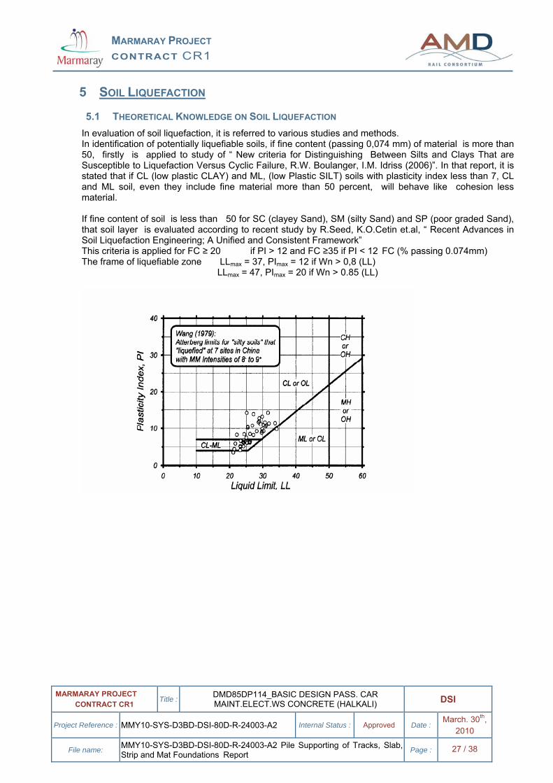
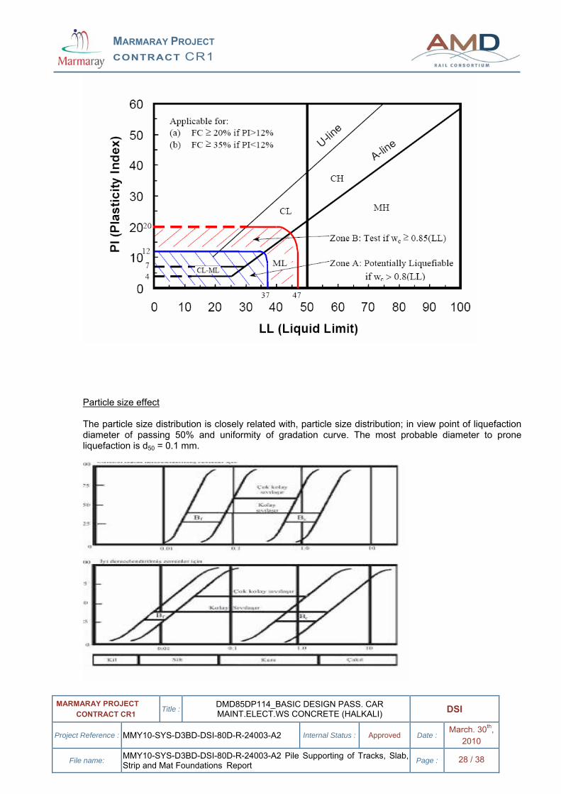
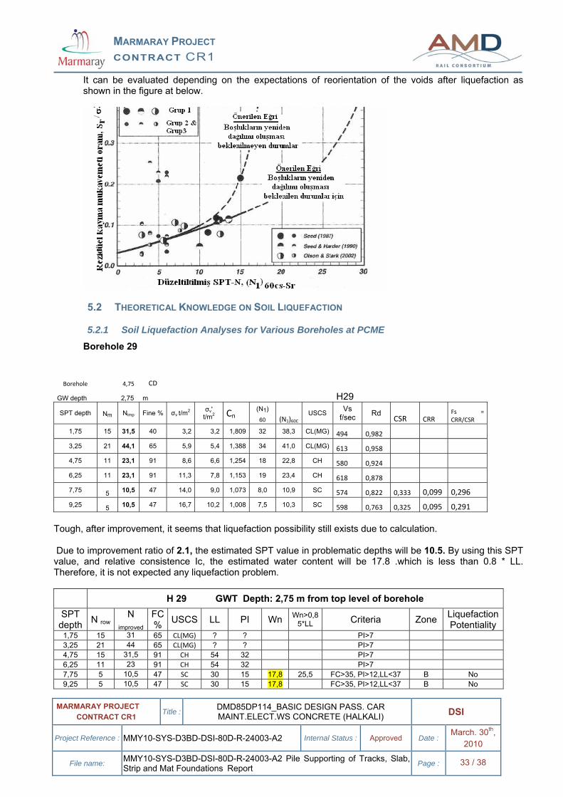
5.1 THEORETICAL KNOWLEDGE ON SOIL LIQUEFACTION In evaluation of soil liquefaction, it is referred to various studies and methods. In identification of potentially liquefiable soils, if fine content (passing 0,074 mm) of material is more than 50, firstly is applied to study of “ New criteria for Distinguishing Between Silts and Clays That are Susceptible to Liquefaction Versus Cyclic Failure, R.W. Boulanger, I.M. Idriss (2006)”. In that report, it is stated that if CL (low plastic CLAY) and ML, (low Plastic SILT) soils with plasticity index less than 7, CL and ML soil, even they include fine material more than 50 percent, will behave like cohesion less material. If fine content of soil is less than 50 for SC (clayey Sand), SM (silty Sand) and SP (poor graded Sand), that soil layer is evaluated according to recent study by R.Seed, K.O.Cetin et.al, “ Recent Advances in Soil Liquefaction Engineering; A Unified and Consistent Framework” This criteria is applied for FC ≥ 20 if PI > 12 and FC ≥35 if PI < 12 FC (% passing 0.074mm) The frame of liquefiable zone LLmax = 37, PImax = 12 if Wn > 0,8 (LL) LLmax = 47, PImax = 20 if Wn > 0.85 (LL)
MARMARAY PROJECT CONTRACT CR1
MARMARAY PROJECT CONTRACT CR1 Title : DMD85DP114_BASIC DESIGN PASS. CAR
MAINT.ELECT.WS CONCRETE (HALKALI) DSI
Project Reference : MMY10-SYS-D3BD-DSI-80D-R-24003-A2 Internal Status : Approved Date : March. 30th, 2010
File name: MMY10-SYS-D3BD-DSI-80D-R-24003-A2 Pile Supporting of Tracks, Slab, Strip and Mat Foundations Report Page : 28 / 38
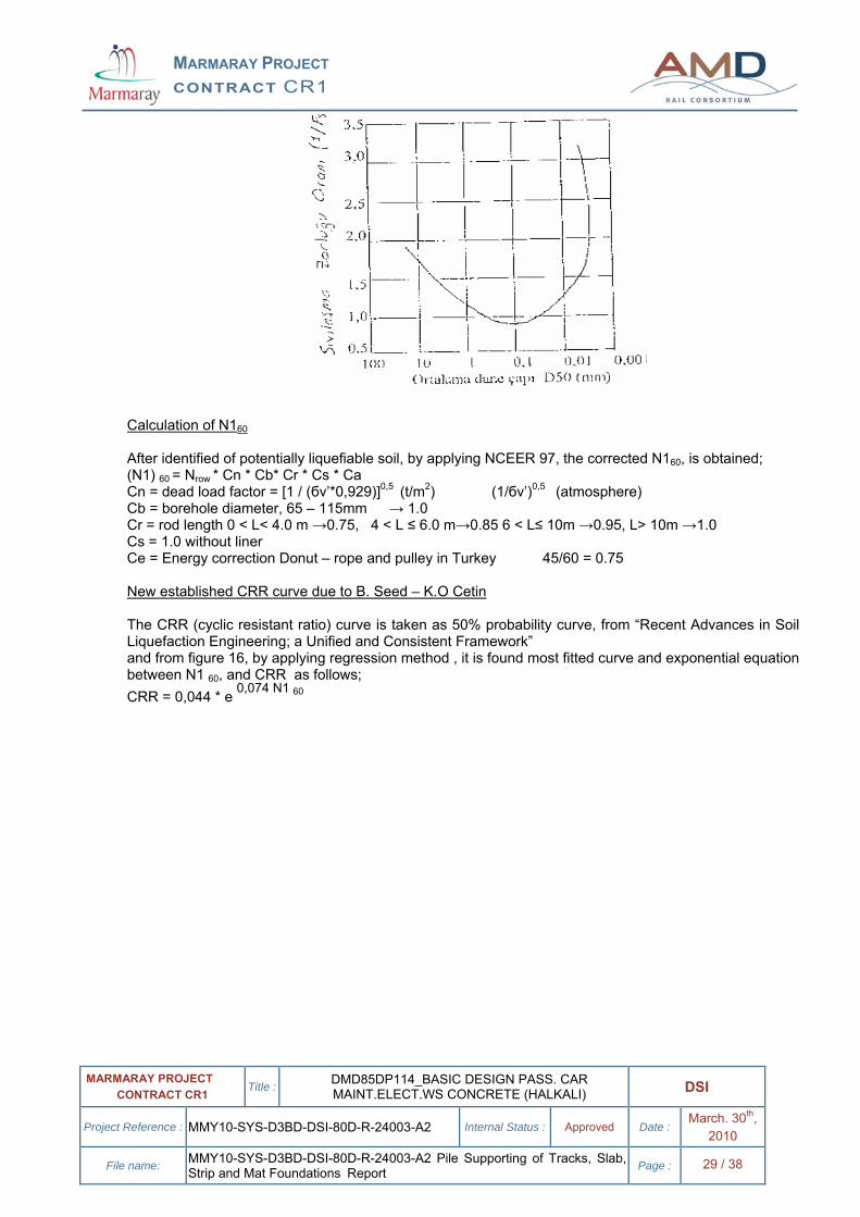
Particle size effect The particle size distribution is closely related with, particle size distribution; in view point of liquefaction diameter of passing 50% and uniformity of gradation curve. The most probable diameter to prone liquefaction is d50 = 0.1 mm.
MARMARAY PROJECT CONTRACT CR1
MARMARAY PROJECT CONTRACT CR1 Title : DMD85DP114_BASIC DESIGN PASS. CAR
MAINT.ELECT.WS CONCRETE (HALKALI) DSI
Project Reference : MMY10-SYS-D3BD-DSI-80D-R-24003-A2 Internal Status : Approved Date : March. 30th, 2010
File name: MMY10-SYS-D3BD-DSI-80D-R-24003-A2 Pile Supporting of Tracks, Slab, Strip and Mat Foundations Report Page : 29 / 38
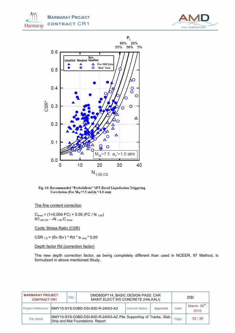
Calculation of N160 After identified of potentially liquefiable soil, by applying NCEER 97, the corrected N160, is obtained; (N1) 60 = Nrow * Cn * Cb* Cr * Cs * Ca Cn = dead load factor = [1 / (бv’*0,929)]0,5 (t/m2) (1/бv’)0,5 (atmosphere) Cb = borehole diameter, 65 – 115mm → 1.0 Cr = rod length 0 < L< 4.0 m →0.75, 4 < L ≤ 6.0 m→0.85 6 < L≤ 10m →0.95, L> 10m →1.0 Cs = 1.0 without liner Ce = Energy correction Donut – rope and pulley in Turkey 45/60 = 0.75 New established CRR curve due to B. Seed – K.O Cetin The CRR (cyclic resistant ratio) curve is taken as 50% probability curve, from “Recent Advances in Soil Liquefaction Engineering; a Unified and Consistent Framework” and from figure 16, by applying regression method , it is found most fitted curve and exponential equation between N1 60, and CRR as follows; CRR = 0,044 * e 0,074 N1 60
MARMARAY PROJECT CONTRACT CR1
MARMARAY PROJECT CONTRACT CR1 Title : DMD85DP114_BASIC DESIGN PASS. CAR
MAINT.ELECT.WS CONCRETE (HALKALI) DSI
Project Reference : MMY10-SYS-D3BD-DSI-80D-R-24003-A2 Internal Status : Approved Date : March. 30th, 2010
File name: MMY10-SYS-D3BD-DSI-80D-R-24003-A2 Pile Supporting of Tracks, Slab, Strip and Mat Foundations Report Page : 30 / 38
The fine content correction Cfines = (1+0,004 FC) + 0.05 (FC / N 1,60) N1,60 CS →N 1,60 C fines Cyclic Stress Ratio (CSR) CSR 7,5 = (бv /бv’) * Rd * a max * 0,65 Depth factor Rd (correction factor) The new depth correction factor, as being completely different than used in NCEER, 97 Method, is formulized in above mentioned Study.
MARMARAY PROJECT CONTRACT CR1
MARMARAY PROJECT CONTRACT CR1 Title : DMD85DP114_BASIC DESIGN PASS. CAR
MAINT.ELECT.WS CONCRETE (HALKALI) DSI
Project Reference : MMY10-SYS-D3BD-DSI-80D-R-24003-A2 Internal Status : Approved Date : March. 30th, 2010
File name: MMY10-SYS-D3BD-DSI-80D-R-24003-A2 Pile Supporting of Tracks, Slab, Strip and Mat Foundations Report Page : 31 / 38
In new depth correction formula, earthquake magnitude (Mw), earthquake acceleration amax, the depth of SPT (d) and average shear wave velocity within the first 40 feet (Vs f/sec)) are used. Since there is no any direct data, Vs is estimated from SPT value due to following formula; Vs = 62.14 N^0,219 * d0,23 * k * (1/0.3048) ft/sec (Ohta and Goto,1978) The standard variation (б) from the average curve, which is shown at the end of formula, is not taken into account. For > 65 feet, the second formula is used. Correction factor (k) in estimation of shear velocity (Vs) Clay = 1.000 Fine sand = 1.009 Medium sand = 1.029 Coarse sand = 1.073 Sand and gravel mixture = 1.151 Gravel = 1.485 Selected safety factor against to liquefaction CRR /CSR ≥ 1.15 Deformation after liquefaction (in saturated condition) Since, the GWL (ground water table level) can be considered as + 2.00, all the layers can be accepted as saturated condition. In calculation of saturated deformation, two methods, which are defined as below will be followed.
The first method is developed by Tokimatsu & Seed, (1987).
MARMARAY PROJECT CONTRACT CR1
MARMARAY PROJECT CONTRACT CR1 Title : DMD85DP114_BASIC DESIGN PASS. CAR
MAINT.ELECT.WS CONCRETE (HALKALI) DSI
Project Reference : MMY10-SYS-D3BD-DSI-80D-R-24003-A2 Internal Status : Approved Date : March. 30th, 2010
File name: MMY10-SYS-D3BD-DSI-80D-R-24003-A2 Pile Supporting of Tracks, Slab, Strip and Mat Foundations Report Page : 32 / 38
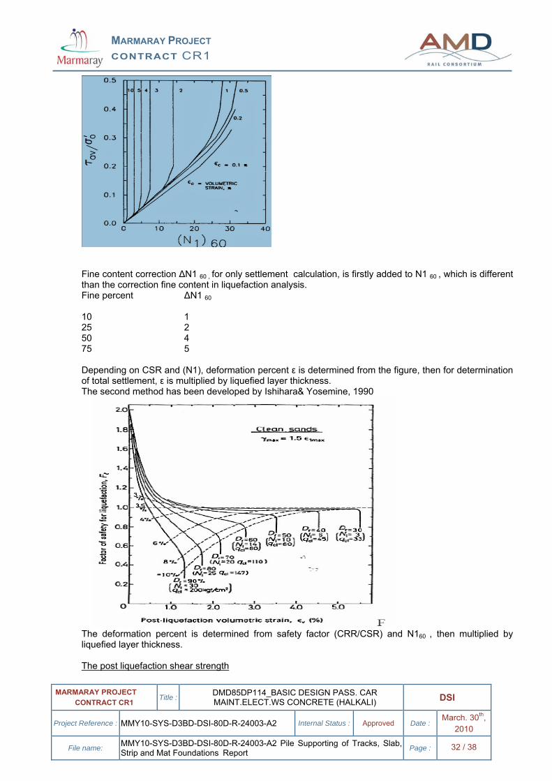
Fine content correction ∆N1 60 , for only settlement calculation, is firstly added to N1 60 , which is different than the correction fine content in liquefaction analysis. Fine percent ∆N1 60 10 1 25 2 50 4 75 5 Depending on CSR and (N1), deformation percent ε is determined from the figure, then for determination of total settlement, ε is multiplied by liquefied layer thickness. The second method has been developed by Ishihara& Yosemine, 1990
The deformation percent is determined from safety factor (CRR/CSR) and N160 , then multiplied by liquefied layer thickness. The post liquefaction shear strength
MARMARAY PROJECT CONTRACT CR1
MARMARAY PROJECT CONTRACT CR1 Title : DMD85DP114_BASIC DESIGN PASS. CAR
MAINT.ELECT.WS CONCRETE (HALKALI) DSI
Project Reference : MMY10-SYS-D3BD-DSI-80D-R-24003-A2 Internal Status : Approved Date : March. 30th, 2010
File name: MMY10-SYS-D3BD-DSI-80D-R-24003-A2 Pile Supporting of Tracks, Slab, Strip and Mat Foundations Report Page : 33 / 38
It can be evaluated depending on the expectations of reorientation of the voids after liquefaction as shown in the figure at below.
5.2 THEORETICAL KNOWLEDGE ON SOIL LIQUEFACTION
5.2.1 Soil Liquefaction Analyses for Various Boreholes at PCME
Borehole 29
Borehole 4,75 CD
GW depth 2,75 m H29
SPT depth Nm Nimp Fine % σv t/m2 σv' t/m2 Cn
(N1) 60 (N1)60C
USCS Vs f/sec Rd
CSR CRR Fs = CRR/CSR
1,75 15 31,5 40 3,2 3,2 1,809 32 38,3 CL(MG) 494 0,982
3,25 21 44,1 65 5,9 5,4 1,388 34 41,0 CL(MG) 613 0,958 4,75 11 23,1 91 8,6 6,6 1,254 18 22,8 CH 580 0,924 6,25 11 23,1 91 11,3 7,8 1,153 19 23,4 CH 618 0,878
7,75 5 10,5 47 14,0 9,0 1,073 8,0 10,9 SC 574 0,822 0,333 0,099 0,296 9,25 5 10,5 47 16,7 10,2 1,008 7,5 10,3 SC 598 0,763 0,325 0,095 0,291
Tough, after improvement, it seems that liquefaction possibility still exists due to calculation. Due to improvement ratio of 2.1, the estimated SPT value in problematic depths will be 10.5. By using this SPT value, and relative consistence Ic, the estimated water content will be 17.8 .which is less than 0.8 * LL. Therefore, it is not expected any liquefaction problem.
H 29 GWT Depth: 2,75 m from top level of borehole SPT
depth N row N improved
FC % USCS LL PI Wn Wn>0,8
5*LL Criteria Zone Liquefaction Potentiality
1,75 15 31 65 CL(MG) ? ? PI>7 3,25 21 44 65 CL(MG) ? ? PI>7 4,75 15 31,5 91 CH 54 32 PI>7 6,25 11 23 91 CH 54 32 PI>7 7,75 5 10,5 47 SC 30 15 17,8 25,5 FC>35, PI>12,LL<37 B No 9,25 5 10,5 47 SC 30 15 17,8 FC>35, PI>12,LL<37 B No
MARMARAY PROJECT CONTRACT CR1
MARMARAY PROJECT CONTRACT CR1 Title : DMD85DP114_BASIC DESIGN PASS. CAR
MAINT.ELECT.WS CONCRETE (HALKALI) DSI
Project Reference : MMY10-SYS-D3BD-DSI-80D-R-24003-A2 Internal Status : Approved Date : March. 30th, 2010
File name: MMY10-SYS-D3BD-DSI-80D-R-24003-A2 Pile Supporting of Tracks, Slab, Strip and Mat Foundations Report Page : 34 / 38
10,75 10 21 95 CH 58 37 PI>7
H29 Passing Percent From Various Screen Size Depth 10 mm 1,0 mm 0,1 m mm d50
7,5 - 8,0 m 99 90 53 0,085 mm
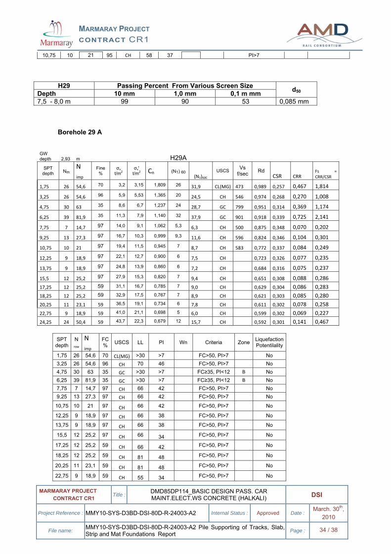
Borehole 29 A
GW depth 2,93 m H29A
SPT depth Nm
N imp
Fine %
σv t/m2
σv' t/m2 Cn (N1) 60
(N1)60C USCS Vs
f/sec Rd CSR CRR
Fs = CRR/CSR
1,75 26 54,6 70 3,2 3,15 1,809 26 31,9 CL(MG) 473 0,989 0,257 0,467 1,814
3,25 26 54,6 96 5,9 5,53 1,365 20 24,5 CH 546 0,974 0,268 0,270 1,008
4,75 30 63 35 8,6 6,7 1,237 24 28,7 GC 799 0,951 0,314 0,369 1,174
6,25 39 81,9 35 11,3 7,9 1,140 32 37,9 GC 901 0,918 0,339 0,725 2,141
7,75 7 14,7 97 14,0 9,1 1,062 5,3 6,3 CH 500 0,875 0,348 0,070 0,202
9,25 13 27,3 97 16,7 10,3 0,999 9,3 11,6 CH 596 0,824 0,346 0,104 0,301
10,75 10 21 97 19,4 11,5 0,945 7 8,7 CH 583 0,772 0,337 0,084 0,249
12,25 9 18,9 97 22,1 12,7 0,900 6 7,5 CH 0,723 0,326 0,077 0,235
13,75 9 18,9 97 24,8 13,9 0,860 6 7,2 CH 0,684 0,316 0,075 0,237
15,5 12 25,2 97 27,9 15,3 0,820 7 9,4 CH 0,651 0,308 0,088 0,286
17,25 12 25,2 59 31,1 16,7 0,785 7 9,0 CH 0,629 0,304 0,086 0,283
18,25 12 25,2 59 32,9 17,5 0,767 7 8,9 CH 0,621 0,303 0,085 0,280
20,25 11 23,1 59 36,5 19,1 0,734 6 7,8 CH 0,611 0,302 0,078 0,258
22,75 9 18,9 59 41,0 21,1 0,698 5 6,0 CH 0,599 0,302 0,069 0,227
24,25 24 50,4 59 43,7 22,3 0,679 12 15,7 CH 0,592 0,301 0,141 0,467 SPT
depth N row
N imp
FC % USCS LL PI Wn Criteria Zone Liquefaction
Potentilality
1,75 26 54,6 70 CL(MG) >30 >7 FC>50, PI>7 No 3,25 26 54,6 96 CH 70 46 FC>50, PI>7 No 4,75 30 63 35 GC >30 >7 FC≥35, PI<12 B No 6,25 39 81,9 35 GC >30 >7 FC≥35, PI<12 B No 7,75 7 14,7 97 CH 66 42 FC>50, PI>7 No 9,25 13 27,3 97 CH 66 42 FC>50, PI>7 No
10,75 10 21 97 CH 66 42 FC>50, PI>7 No
12,25 9 18,9 97 CH 66 38 FC>50, PI>7 No
13,75 9 18,9 97 CH 66 38 FC>50, PI>7 No
15,5 12 25,2 97 CH 66 34 FC>50, PI>7 No
17,25 12 25,2 59 CH 66 42 FC>50, PI>7 No
18,25 12 25,2 59 CH 81 48 FC>50, PI>7 No
20,25 11 23,1 59 CH 81 48 FC>50, PI>7 No
22,75 9 18,9 59 CH 55 34 FC>50, PI>7 No
MARMARAY PROJECT CONTRACT CR1
MARMARAY PROJECT CONTRACT CR1 Title : DMD85DP114_BASIC DESIGN PASS. CAR
MAINT.ELECT.WS CONCRETE (HALKALI) DSI
Project Reference : MMY10-SYS-D3BD-DSI-80D-R-24003-A2 Internal Status : Approved Date : March. 30th, 2010
File name: MMY10-SYS-D3BD-DSI-80D-R-24003-A2 Pile Supporting of Tracks, Slab, Strip and Mat Foundations Report Page : 35 / 38
24,25 24 50,4 59 CH 55 34 FC>50, PI>7 No
Borehole 35
SPT depth
N row
N improve
FC % USCS LL PI Wn Criteria Zone Liquefaction
Potentilality 1,75 14 29,4 (MG) ? ? ? No, Above GWL 3,25 8 16,8 98 CH 56 33 FC>50, PI>7 No 4,75 10 21 98 CH 56 33 31,0 FC>50, PI>7 No 6,25 9 18,9 98 CH 56 33 FC>50, PI>7 No 7,75 4 8,4 98 CH 56 33 FC>50, PI>7 No 9,25 4 8,4 98 CH 56 33 FC>50, PI>7 No 10,75 7 14,7 98 CH 68 44 56,0 FC>50, PI>7 No 12,25 6 12,6 98 CH 68 44 FC>50, PI>7 No 13,75 6 12,6 98 CH 68 44 FC>50, PI>7 No 15,25 7 14,7 94 CH 60 38 FC>50, PI>7 No 16,75 2 4,2 94 CH 60 38 FC>50, PI>7 No 18,25 8 16,8 94 CH 60 38 FC>50, PI>7 No 19,75 6 12,6 80 CH 60 37 56,0 FC>50, PI>7 No 21,25 15 31,5 80 CH 62 42 FC>50, PI>7 No
22,75 16 33,6 24 SC ? ? FC>20, PI>12 A, B Yes
GW depth 1,89 m H35
SPT depth
N improved
Fine % σv t/m2 σv'
t/m2 Cn (N1) 60(N1)60C
USCS Vs f/sec Rd
CSR CRR Fs = CRR/CSR
H UP
LAYER H
DOWN
LAYER
Ishihara H1 /H2
22,75 33,6 24 41,0 20,1 0,716 18 21,0 SC 0,519 0,275 0,208 0,756 23.70 3.0 sufficient
There will be no any liquefaction risk around borehole H35.
Borehole 36
SPT depth Nm
N imp
Fine %
σv t/m2
σv' t/m2 Cn
(N1) 60 (N1)60C
USCS Vs f/sec Rd
CSR CRR Fs = CRR/CSR
H UP
LAYER H
DOWN
LAYER
Ishihara H1 /H2
7,75 3 6,3 7 14,0 8,5 1,104 2 2,8 SM 436 0,690 0,296 0,054 0,183 7,94 1,3 Sufficient
22,75 30 63 41 41,0 20,5 0,710 16 20,0 SC 0,464 0,242 0,193 0,797 22,74 1,5 Sufficient
SPT depth N row N
improved FC % USCS LL PI Wn Criteria Zone Liquefaction
Potentilality 1,75 28 58,8 (MG) ? ? GRAVEL No 3,25 11 23,1 90 CL 48 25 FC>50, PI>7 No 4,75 10 21 90 CL 48 25 27,0 FC>50, PI>7 No 6,25 5 10,5 90 CL 48 25 FC>50, PI>7 No 7,75 3 6,3 7 SM NP NP FC>20, PI>12 A Yes 9,25 5 10,5 65 CL 43 26 FC>50, PI>7 No
10,75 6 12,6 65 CL 43 26 FC>50, PI>7 No
12,25 6 12,6 65 CH 52 33 40,0 FC>50, PI>7 No
13,75 7 14,7 65 CH 52 33 FC>50, PI>7 No
MARMARAY PROJECT CONTRACT CR1
MARMARAY PROJECT CONTRACT CR1 Title : DMD85DP114_BASIC DESIGN PASS. CAR
MAINT.ELECT.WS CONCRETE (HALKALI) DSI
Project Reference : MMY10-SYS-D3BD-DSI-80D-R-24003-A2 Internal Status : Approved Date : March. 30th, 2010
File name: MMY10-SYS-D3BD-DSI-80D-R-24003-A2 Pile Supporting of Tracks, Slab, Strip and Mat Foundations Report Page : 36 / 38
There will be
no any liquefaction risk around borehole H36.
Borehole 38
SPT depth
N row
N imp
FC % USCS LL PI 0.85*
LL Wn
improved Criteria Zone Liquefaction Potentilality
1,75 9 18,9 71 CL 44 24 FC>50, PI>7 No
3,25 24 50,4 71 CL 44 24 FC>50, PI>7 No
4,75 2 4,2 53 CL 31 16 26,4 26,9* FC>50, PI>7 A,B No
6,25 2 4,2 53 CL 31 16 26,4 26,9* FC>50, PI>7 A,B No
7,75 2 4,2 53 CL 31 16 26,4 26,9* FC>20, PI>12 A,B No
9,25 3 6,3 53 CL 31 16 26,4 25,7* FC>50, PI>7 A,B No
10,75 4 8,4 53 CL 31 16 26,4 22,2* FC>50, PI>7 A,B No
12,25 4 8,4 53 CL 31 16 26,4 22,2* FC>50, PI>7 A,B No
13,75 5 10,5 53 CH 58 37 FC>50, PI>7 No
15,25 7 14,7 87 CL 48 28 FC>50, PI>7 No
16,75 8 16,8 87 CL 48 28 FC>50, PI>7 No
18,25 9 18,9 87 CL 42 24 FC>50, PI>7 No
19,75 8 16,8 87 CL 42 24 FC>50, PI>7 No
21,25 8 16,8 87 CL 47 27 FC>50, PI>7 No
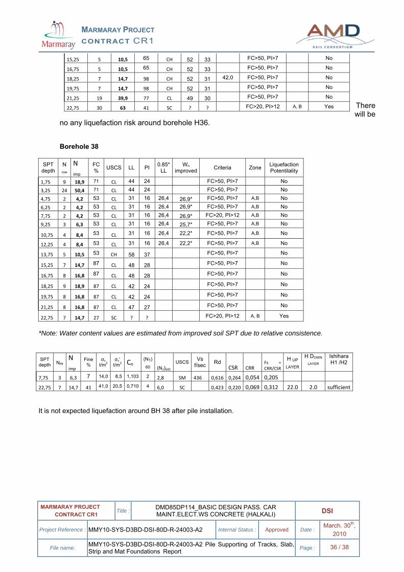
22,75 7 14,7 27 SC ? ? FC>20, PI>12 A, B Yes
*Note: Water content values are estimated from improved soil SPT due to relative consistence.
SPT depth Nm
N imp
Fine %
σv t/m2
σv' t/m2 Cn
(N1) 60 (N1)60C
USCS Vs f/sec Rd
CSR CRR Fs = CRR/CSR
H UP
LAYER
H DOWN
LAYER Ishihara H1 /H2
7,75 3 6,3 7 14,0 8,5 1,103 2 2,8 SM 436 0,616 0,264 0,054 0,205 22,75 7 14,7 41 41,0 20,5 0,710 4 6,0 SC 0,423 0,220 0,069 0,312 22.0 2.0 sufficient
It is not expected liquefaction around BH 38 after pile installation.
15,25 5 10,5 65 CH 52 33 FC>50, PI>7 No
16,75 5 10,5 65 CH 52 33 FC>50, PI>7 No
18,25 7 14,7 98 CH 52 31 42,0 FC>50, PI>7 No
19,75 7 14,7 98 CH 52 31 FC>50, PI>7 No
21,25 19 39,9 77 CL 49 30 FC>50, PI>7 No
22,75 30 63 41 SC ? ? FC>20, PI>12 A, B Yes
MARMARAY PROJECT CONTRACT CR1
MARMARAY PROJECT CONTRACT CR1 Title : DMD85DP114_BASIC DESIGN PASS. CAR
MAINT.ELECT.WS CONCRETE (HALKALI) DSI
Project Reference : MMY10-SYS-D3BD-DSI-80D-R-24003-A2 Internal Status : Approved Date : March. 30th, 2010
File name: MMY10-SYS-D3BD-DSI-80D-R-24003-A2 Pile Supporting of Tracks, Slab, Strip and Mat Foundations Report Page : 37 / 38
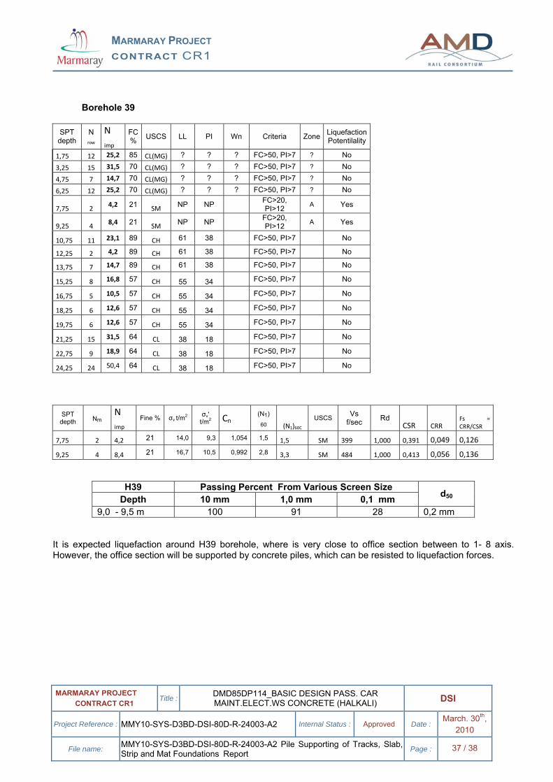
Borehole 39
SPT depth
N row
N imp
FC % USCS LL PI Wn Criteria Zone Liquefaction
Potentilality
1,75 12 25,2 85 CL(MG) ? ? ? FC>50, PI>7 ? No
3,25 15 31,5 70 CL(MG) ? ? ? FC>50, PI>7 ? No
4,75 7 14,7 70 CL(MG) ? ? ? FC>50, PI>7 ? No
6,25 12 25,2 70 CL(MG) ? ? ? FC>50, PI>7 ? No
7,75 2 4,2 21 SM NP NP FC>20, PI>12 A Yes
9,25 4 8,4 21 SM NP NP FC>20, PI>12 A Yes
10,75 11 23,1 89 CH 61 38 FC>50, PI>7 No
12,25 2 4,2 89 CH 61 38 FC>50, PI>7 No
13,75 7 14,7 89 CH 61 38 FC>50, PI>7 No
15,25 8 16,8 57 CH 55 34 FC>50, PI>7 No
16,75 5 10,5 57 CH 55 34 FC>50, PI>7 No
18,25 6 12,6 57 CH 55 34 FC>50, PI>7 No
19,75 6 12,6 57 CH 55 34 FC>50, PI>7 No
21,25 15 31,5 64 CL 38 18 FC>50, PI>7 No
22,75 9 18,9 64 CL 38 18 FC>50, PI>7 No
24,25 24 50,4 64 CL 38 18 FC>50, PI>7 No
SPT depth Nm
N imp
Fine % σv t/m2 σv' t/m2 Cn
(N1) 60 (N1)60C
USCS Vs f/sec Rd
CSR CRR Fs = CRR/CSR
7,75 2 4,2 21 14,0 9,3 1,054 1,5 1,5 SM 399 1,000 0,391 0,049 0,126
9,25 4 8,4 21 16,7 10,5 0,992 2,8 3,3 SM 484 1,000 0,413 0,056 0,136
H39 Passing Percent From Various Screen Size Depth 10 mm 1,0 mm 0,1 mm d50
9,0 - 9,5 m 100 91 28 0,2 mm It is expected liquefaction around H39 borehole, where is very close to office section between to 1- 8 axis. However, the office section will be supported by concrete piles, which can be resisted to liquefaction forces.
MARMARAY PROJECT CONTRACT CR1
MARMARAY PROJECT CONTRACT CR1 Title : DMD85DP114_BASIC DESIGN PASS. CAR
MAINT.ELECT.WS CONCRETE (HALKALI) DSI
Project Reference : MMY10-SYS-D3BD-DSI-80D-R-24003-A2 Internal Status : Approved Date : March. 30th, 2010
File name: MMY10-SYS-D3BD-DSI-80D-R-24003-A2 Pile Supporting of Tracks, Slab, Strip and Mat Foundations Report Page : 38 / 38
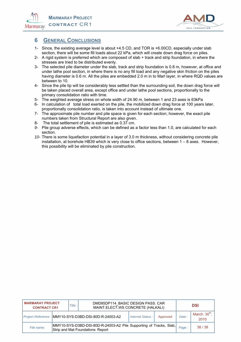
6 GENERAL CONCLUSIONS 1- Since, the existing average level is about +4.5 CD, and TOR is +6.00CD, especially under slab
section, there will be some fill loads about 22 kPa, which will create down drag force on piles. 2- A rigid system is preferred which are composed of slab + track and strip foundation, in where the
stresses are tried to be distributed evenly. 3- The selected pile diameter under the slab, track and strip foundation is 0.8 m, however, at office and
under lathe pool section, in where there is no any fill load and any negative skin friction on the piles having diameter is 0.6 m. All the piles are embedded 2.0 m in to Marl layer, in where RQD values are between to 10.
4- Since the pile tip will be considerably less settled than the surrounding soil, the down drag force will be taken placed overall area, except office and under lathe pool sections, proportionally to the primary consolidation ratio with time.
5- The weighted average stress on whole width of 24.90 m, between 1 and 23 axes is 63kPa 6- In calculation of total load exerted on the pile, the mobilized down drag force at 100 years later,
proportionally consolidation ratio, is taken into account instead of ultimate one. 7- The approximate pile number and pile space is given for each section; however, the exact pile
numbers taken from Structural Report are also given. 8- The total settlement of pile is estimated as 0.37 cm. 9- Pile group adverse effects, which can be defined as a factor less than 1.0, are calculated for each
section. 10- There is some liquefaction potential in a layer of 3.0 m thickness, without considering concrete pile
installation, at borehole HB39 which is very close to office sections, between 1 – 8 axes. However, this possibility will be eliminated by pile construction.


![Federal Government Surplus (2) [Read-Only]...`Cargo trucks -5 $000 `Grand total – $74,000 $ 600 000 `Civilian/Van Trks-4 $111 000 $1,600,000 $111,000 `That’s“16– `Dump trucks](https://img.pdfslide.us/doc/110x75/60391218e0761c4f570cdb3a/federal-government-surplus-2-read-only-cargo-trucks-5-000-grand-total.jpg)