Embed Size (px)
Citation preview
Christoph ScheyttIHP Leibnizinstitut für Innovative Mikroelektronik GmbH
15236 Frankfurt (Oder), Germany
IHP Im Technologiepark 25 15236 Frankfurt (Oder) Germany www.ihp-microelectronics.com © 2006 - All rights reserved
mm-Wave Sensor and Communications Components at 60, 94, and 122 GHz in
SiGe BiCMOS Technology
Workshop on “Wireless Multi-Gigabit-Systems”, Center for Informatics and Information Technology,
TU Braunschweig, July 2st 2009
IHP Im Technologiepark 25 15236 Frankfurt (Oder) Germany www.ihp-microelectronics.com © 2006 - All rights reserved
Outline
• Silicon technology progress and mm-wave design
• 1 Gbps 60 GHz transceiver (WIGWAM, BMBF)
• 2 – 6 Gbps 60 GHz transceiver (Easy-A, BMBF)
• 94 and 122 GHz components for mm-wave sensing (ISM, ZIM)
• Towards 100 Gbps Wireless Short-Range Communications (TeraCom, Leibniz Excellence Project)
IHP Im Technologiepark 25 15236 Frankfurt (Oder) Germany www.ihp-microelectronics.com © 2006 - All rights reserved
Silicon Technologies for Wireless & Broadband
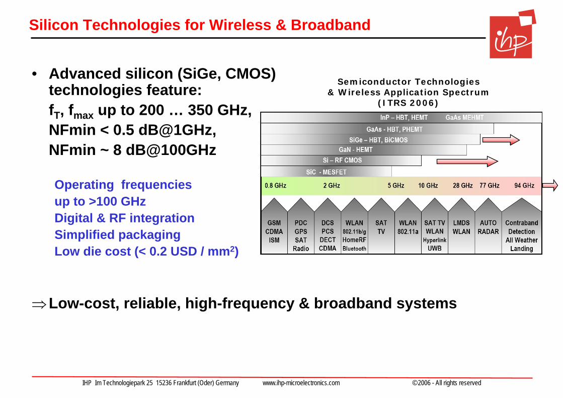
• Advanced silicon (SiGe, CMOS) technologies feature: fT, fmax up to 200 … 350 GHz, NFmin < 0.5 dB@1GHz, NFmin ~ 8 dB@100GHz
Operating frequenciesup to >100 GHzDigital & RF integrationSimplified packagingLow die cost (< 0.2 USD / mm2)
⇒Low-cost, reliable, high-frequency & broadband systems
Semiconductor Technologies & Wireless Application Spectrum
(ITRS 2006)
IHP Im Technologiepark 25 15236 Frankfurt (Oder) Germany www.ihp-microelectronics.com © 2006 - All rights reserved
Silicon technology progress and mm-wave design
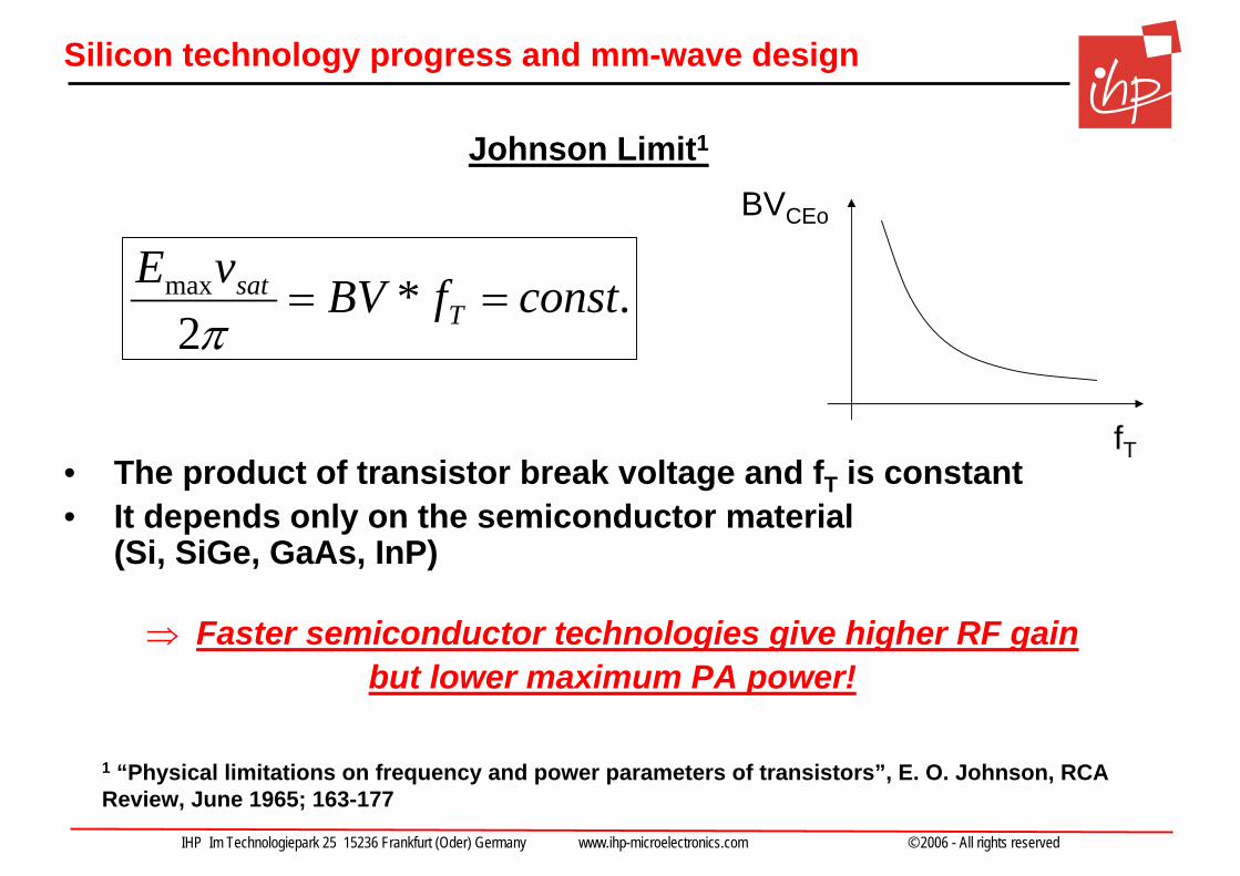
• The product of transistor break voltage and fT is constant• It depends only on the semiconductor material
(Si, SiGe, GaAs, InP)
⇒ Faster semiconductor technologies give higher RF gainbut lower maximum PA power!
1 “Physical limitations on frequency and power parameters of transistors”, E. O. Johnson, RCA Review, June 1965; 163-177
Johnson Limit1
BVCEo
fT
.*2
max constfBVvET
sat ==π
IHP Im Technologiepark 25 15236 Frankfurt (Oder) Germany www.ihp-microelectronics.com © 2006 - All rights reserved
Silicon technology progress and mm-wave design
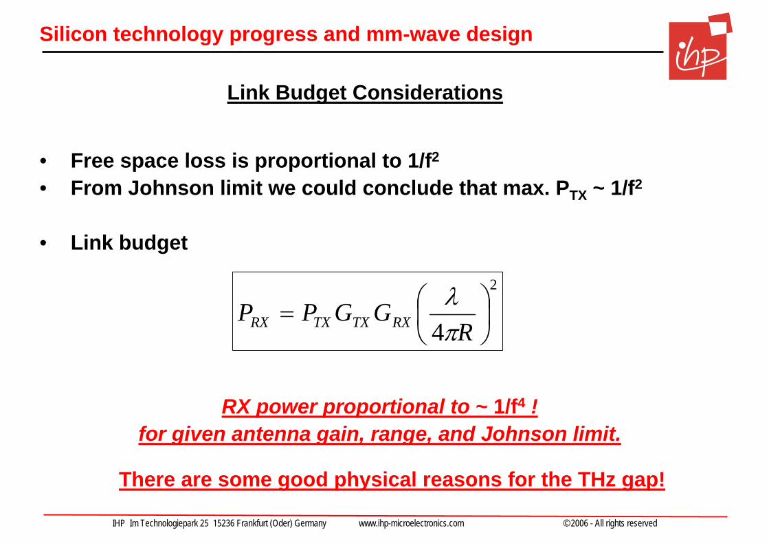
• Free space loss is proportional to 1/f2
• From Johnson limit we could conclude that max. PTX ~ 1/f2
• Link budget
RX power proportional to ~ 1/f4 ! for given antenna gain, range, and Johnson limit.
Link Budget Considerations
2
4⎟⎠⎞
⎜⎝⎛=
RGGPP RXTXTXRX π
λ
There are some good physical reasons for the THz gap!
IHP Im Technologiepark 25 15236 Frankfurt (Oder) Germany www.ihp-microelectronics.com © 2006 - All rights reserved
Silicon technology progress and mm-wave design
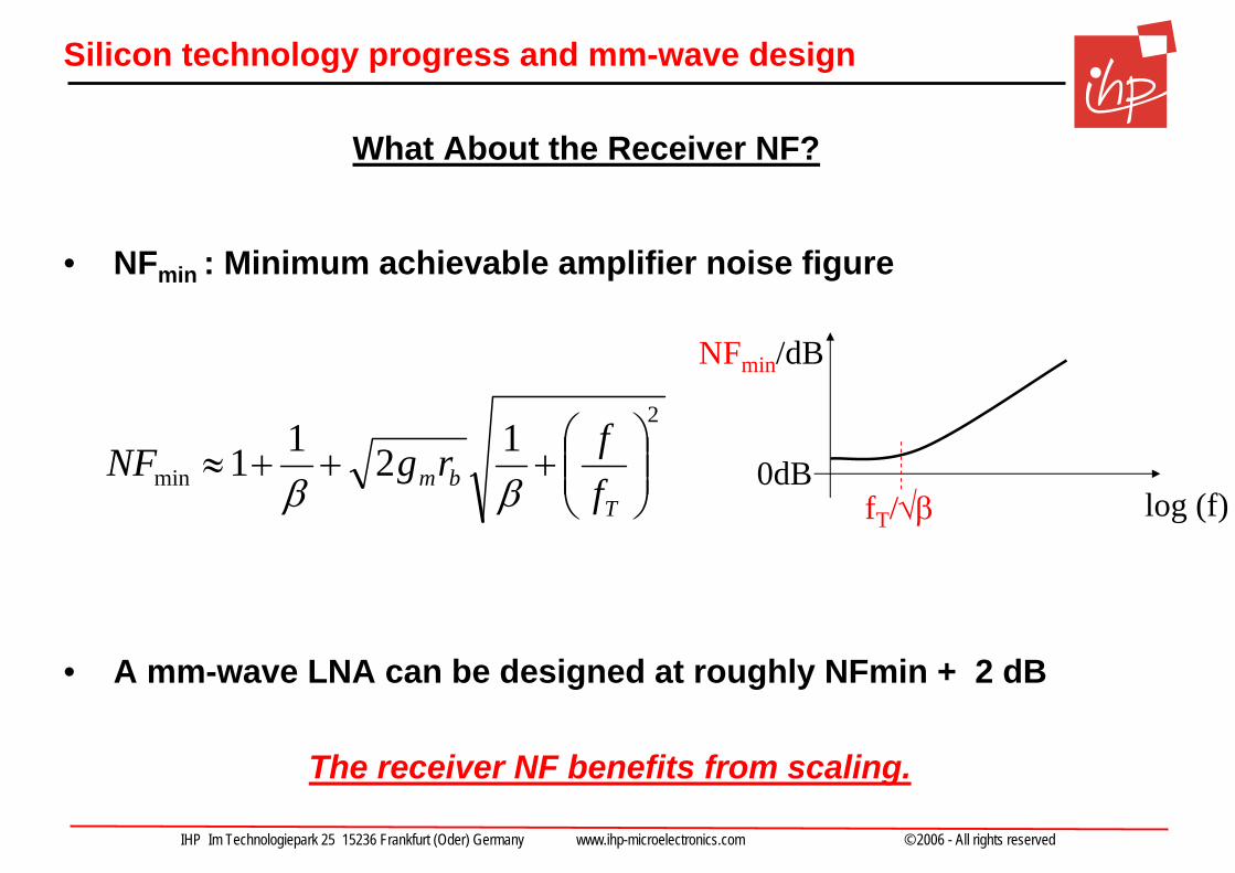
• NFmin : Minimum achievable amplifier noise figure
• A mm-wave LNA can be designed at roughly NFmin + 2 dB
The receiver NF benefits from scaling.
NFmin/dB
log (f)0dB
fT/√β
2
min1211 ⎟⎟
⎠
⎞⎜⎜⎝
⎛+++≈
Tbm f
frgNFββ
What About the Receiver NF?
IHP Im Technologiepark 25 15236 Frankfurt (Oder) Germany www.ihp-microelectronics.com © 2006 - All rights reserved
Silicon technology progress and mm-wave design
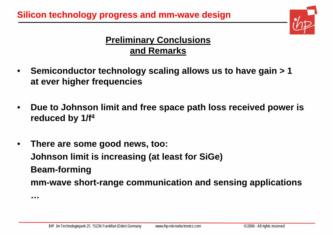
• Semiconductor technology scaling allows us to have gain > 1 at ever higher frequencies
• Due to Johnson limit and free space path loss received power isreduced by 1/f4
• There are some good news, too: Johnson limit is increasing (at least for SiGe)Beam-formingmm-wave short-range communication and sensing applications…
Preliminary Conclusionsand Remarks
IHP Im Technologiepark 25 15236 Frankfurt (Oder) Germany www.ihp-microelectronics.com © 2006 - All rights reserved
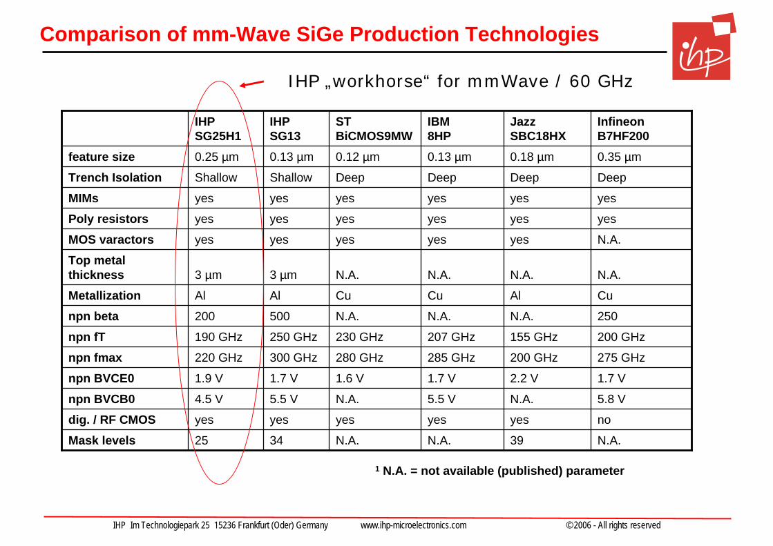
Comparison of mm-Wave SiGe Production Technologies
1 N.A. = not available (published) parameter
N.A.39N.A.N.A.3425Mask levelsnoyesyesyesyesyesdig. / RF CMOS5.8 VN.A.5.5 VN.A.5.5 V4.5 Vnpn BVCB01.7 V2.2 V1.7 V1.6 V1.7 V1.9 Vnpn BVCE0275 GHz200 GHz285 GHz280 GHz300 GHz220 GHznpn fmax200 GHz155 GHz207 GHz230 GHz250 GHz190 GHznpn fT250N.A.N.A.N.A.500200npn betaCuAlCuCuAlAlMetallizationN.A.N.A.N.A.N.A.3 µm3 µm
Top metal thickness
N.A.yesyesyesyesyesMOS varactorsyesyesyesyesyesyesPoly resistorsyesyesyesyesyesyesMIMsDeepDeepDeepDeepShallowShallowTrench Isolation0.35 µm0.18 µm0.13 µm0.12 µm0.13 µm0.25 µmfeature size
Infineon B7HF200
Jazz SBC18HX
IBM 8HP
ST BiCMOS9MW
IHP SG13
IHP SG25H1
IHP „workhorse“ for mmWave / 60 GHz
IHP Im Technologiepark 25 15236 Frankfurt (Oder) Germany www.ihp-microelectronics.com © 2006 - All rights reserved
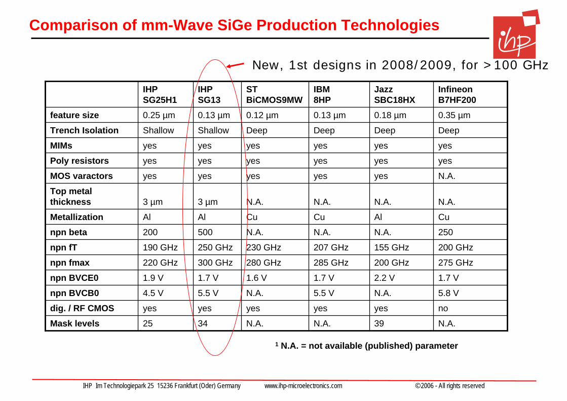
Comparison of mm-Wave SiGe Production Technologies
1 N.A. = not available (published) parameter
N.A.39N.A.N.A.3425Mask levelsnoyesyesyesyesyesdig. / RF CMOS5.8 VN.A.5.5 VN.A.5.5 V4.5 Vnpn BVCB01.7 V2.2 V1.7 V1.6 V1.7 V1.9 Vnpn BVCE0275 GHz200 GHz285 GHz280 GHz300 GHz220 GHznpn fmax200 GHz155 GHz207 GHz230 GHz250 GHz190 GHznpn fT250N.A.N.A.N.A.500200npn betaCuAlCuCuAlAlMetallizationN.A.N.A.N.A.N.A.3 µm3 µm
Top metal thickness
N.A.yesyesyesyesyesMOS varactorsyesyesyesyesyesyesPoly resistorsyesyesyesyesyesyesMIMsDeepDeepDeepDeepShallowShallowTrench Isolation0.35 µm0.18 µm0.13 µm0.12 µm0.13 µm0.25 µmfeature size
Infineon B7HF200
Jazz SBC18HX
IBM 8HP
ST BiCMOS9MW
IHP SG13
IHP SG25H1
New, 1st designs in 2008/2009, for >100 GHz
IHP Im Technologiepark 25 15236 Frankfurt (Oder) Germany www.ihp-microelectronics.com © 2006 - All rights reserved
Outline
• Silicon technology progress and mm-wave design
• 1 Gbps 60 GHz transceiver (WIGWAM, BMBF)
• 2 – 6 Gbps 60 GHz transceiver (Easy-A, BMBF)
• 94 and 122 GHz components for mm-wave sensing (ISM, ZIM)
• Towards 100 Gbps Wireless Short-Range Communications (TeraCom, Leibniz Excellence Project)
IHP Im Technologiepark 25 15236 Frankfurt (Oder) Germany www.ihp-microelectronics.com © 2006 - All rights reserved
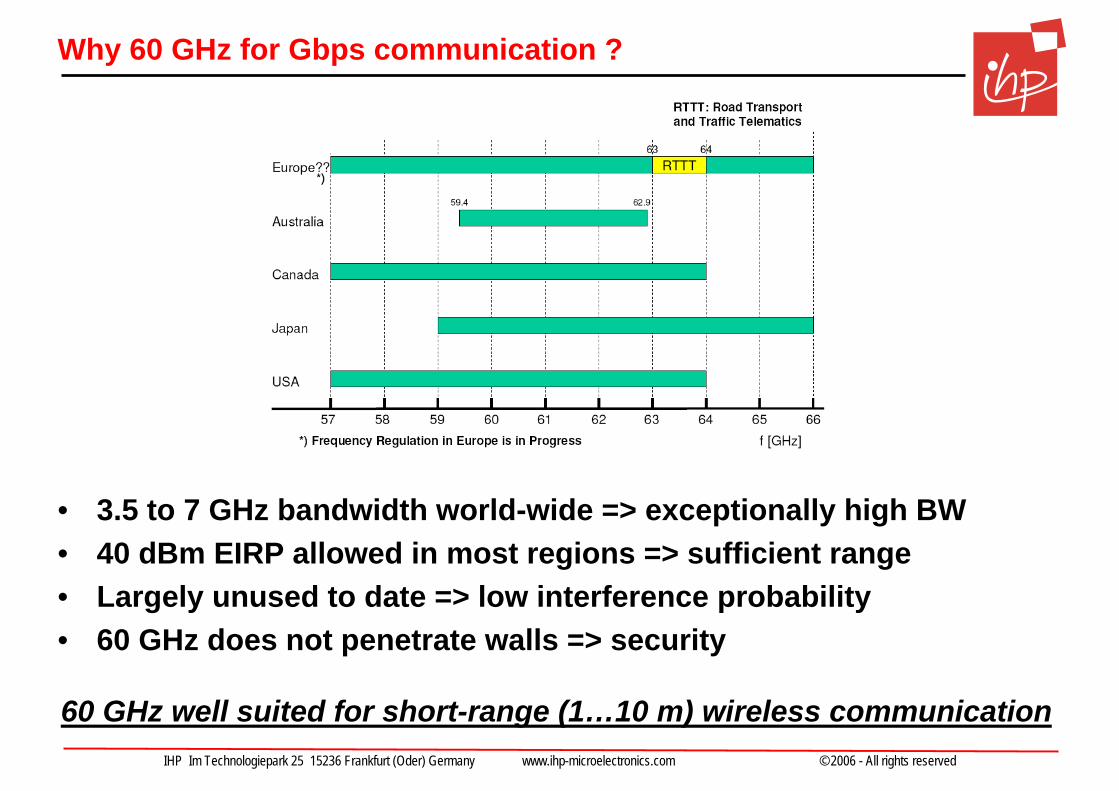
Why 60 GHz for Gbps communication ?
• 3.5 to 7 GHz bandwidth world-wide => exceptionally high BW• 40 dBm EIRP allowed in most regions => sufficient range• Largely unused to date => low interference probability• 60 GHz does not penetrate walls => security
60 GHz well suited for short-range (1…10 m) wireless communication
IHP Im Technologiepark 25 15236 Frankfurt (Oder) Germany www.ihp-microelectronics.com © 2006 - All rights reserved
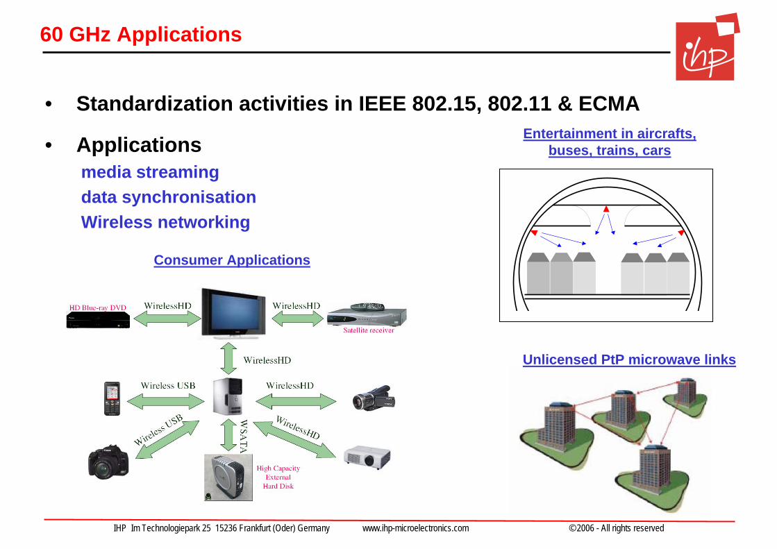
60 GHz Applications
Entertainment in aircrafts, buses, trains, cars
Consumer Applications
Unlicensed PtP microwave links
• Standardization activities in IEEE 802.15, 802.11 & ECMA
• Applicationsmedia streamingdata synchronisationWireless networking
IHP Im Technologiepark 25 15236 Frankfurt (Oder) Germany www.ihp-microelectronics.com © 2006 - All rights reserved
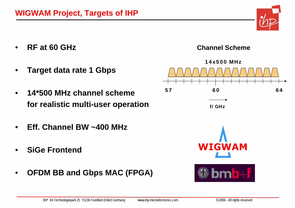
WIGWAM Project, Targets of IHP
• RF at 60 GHz
• Target data rate 1 Gbps
• 14*500 MHz channel schemefor realistic multi-user operation
• Eff. Channel BW ~400 MHz
• SiGe Frontend
• OFDM BB and Gbps MAC (FPGA)
57 60 64
14x500 MHz
f/GHz
Channel Scheme
IHP Im Technologiepark 25 15236 Frankfurt (Oder) Germany www.ihp-microelectronics.com © 2006 - All rights reserved
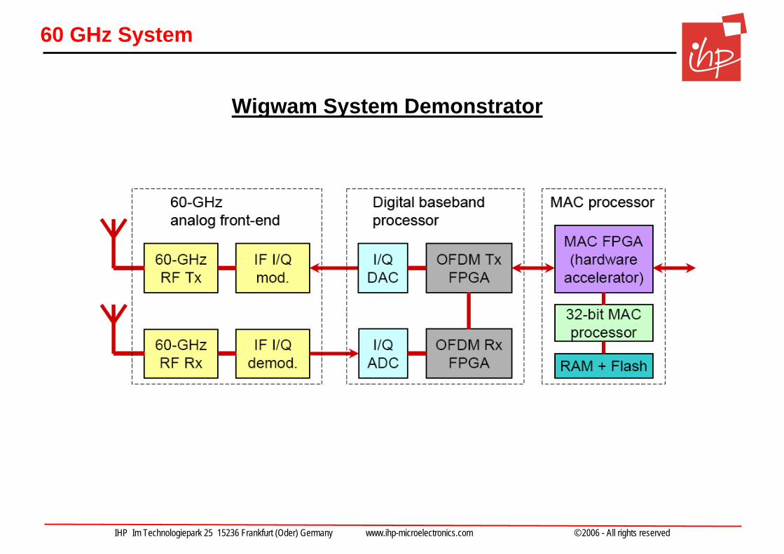
60 GHz System
Wigwam System Demonstrator
IHP Im Technologiepark 25 15236 Frankfurt (Oder) Germany www.ihp-microelectronics.com © 2006 - All rights reserved
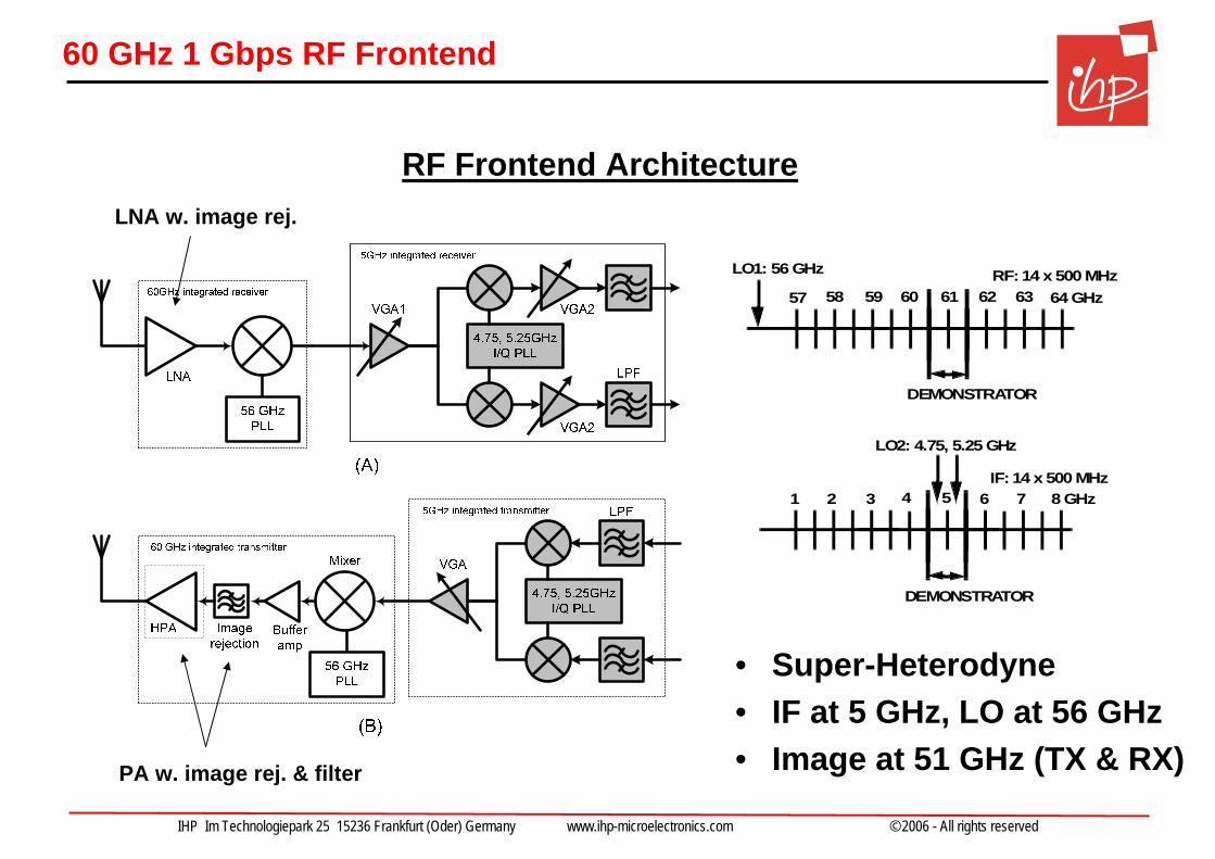
60 GHz 1 Gbps RF Frontend
RF Frontend Architecture
• Super-Heterodyne• IF at 5 GHz, LO at 56 GHz• Image at 51 GHz (TX & RX)
64 GHz57 58 59 60 61 62 63
LO1: 56 GHz
DEMONSTRATOR
RF: 14 x 500 MHz
8 GHz1 2 3 4 5 6 7
LO2: 4.75, 5.25 GHz
DEMONSTRATOR
IF: 14 x 500 MHz
PA w. image rej. & filter
LNA w. image rej.
IHP Im Technologiepark 25 15236 Frankfurt (Oder) Germany www.ihp-microelectronics.com © 2006 - All rights reserved
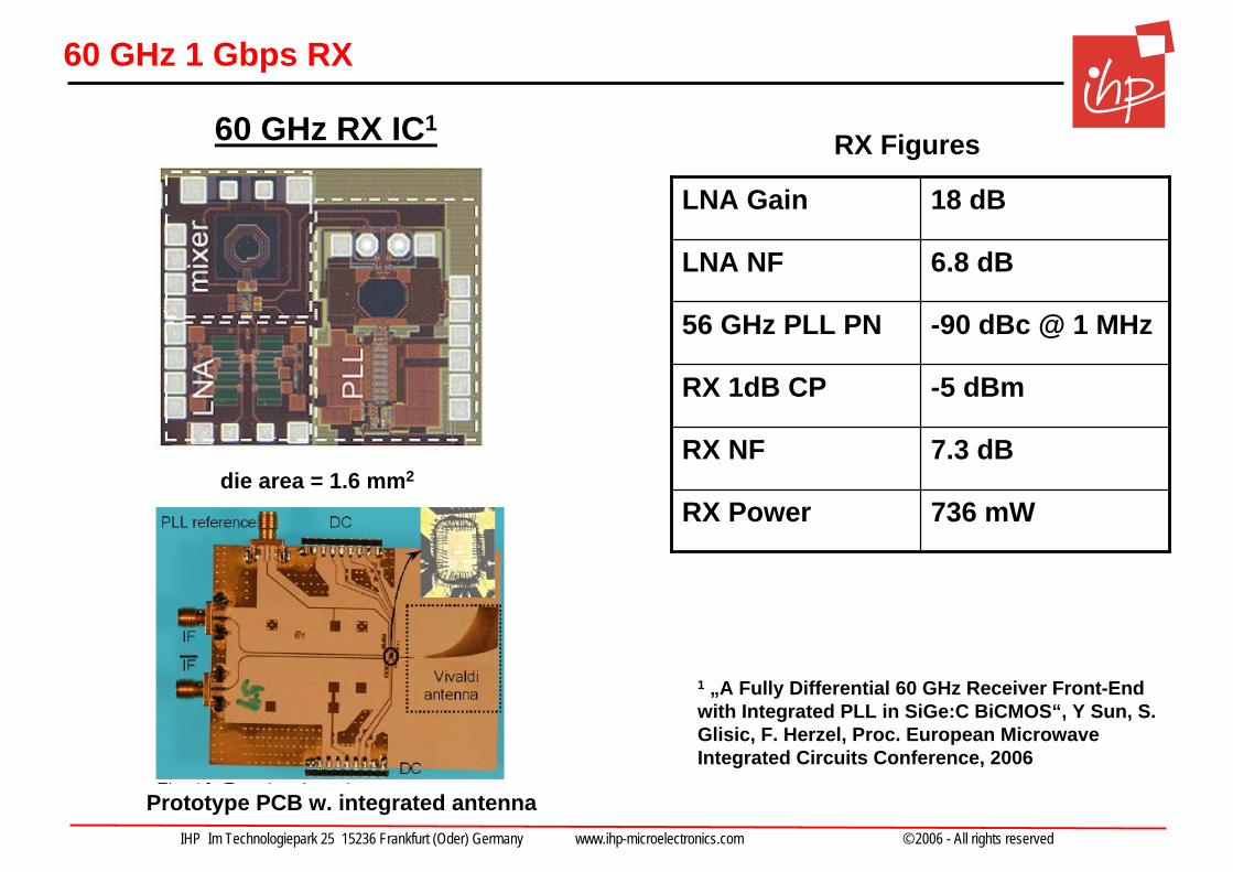
60 GHz 1 Gbps RX
60 GHz RX IC1
Prototype PCB w. integrated antenna
736 mWRX Power
7.3 dBRX NF
-5 dBmRX 1dB CP
-90 dBc @ 1 MHz56 GHz PLL PN
6.8 dBLNA NF
18 dBLNA Gain
1 „A Fully Differential 60 GHz Receiver Front-Endwith Integrated PLL in SiGe:C BiCMOS“, Y Sun, S. Glisic, F. Herzel, Proc. European MicrowaveIntegrated Circuits Conference, 2006
RX Figures
die area = 1.6 mm2
IHP Im Technologiepark 25 15236 Frankfurt (Oder) Germany www.ihp-microelectronics.com © 2006 - All rights reserved
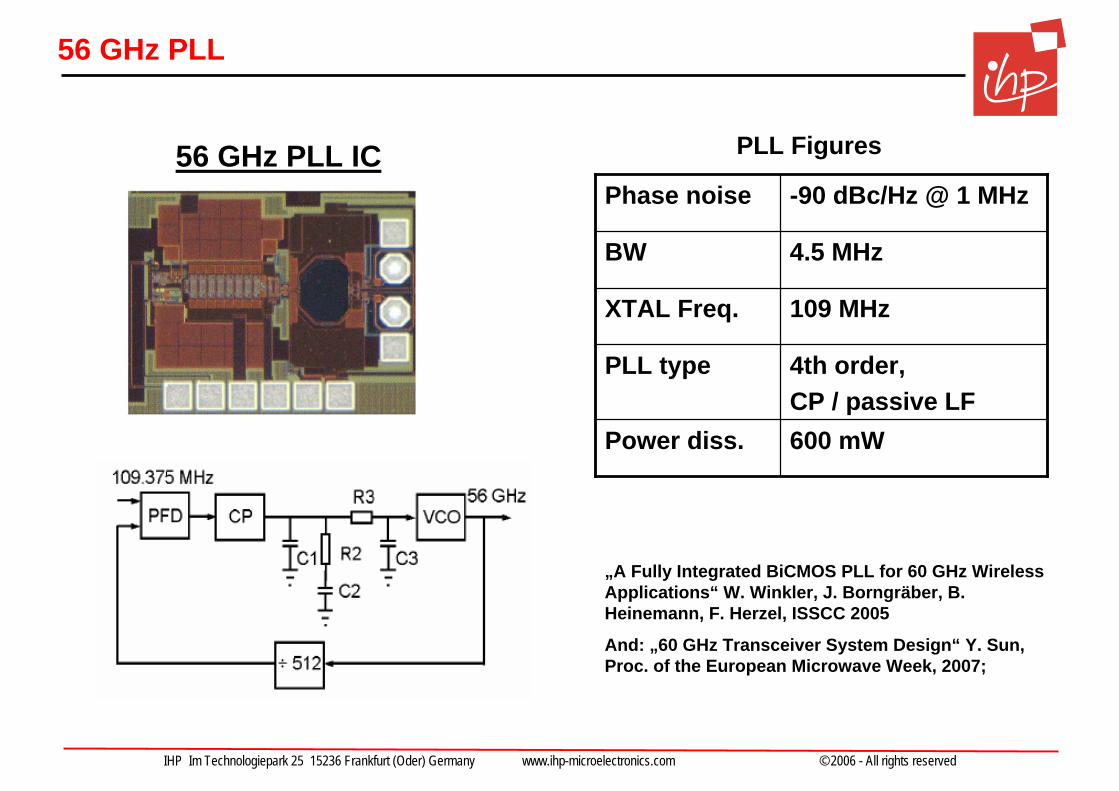
56 GHz PLL
„A Fully Integrated BiCMOS PLL for 60 GHz Wireless Applications“ W. Winkler, J. Borngräber, B. Heinemann, F. Herzel, ISSCC 2005
And: „60 GHz Transceiver System Design“ Y. Sun, Proc. of the European Microwave Week, 2007;
109 MHzXTAL Freq.
600 mWPower diss.
4th order, CP / passive LF
PLL type
4.5 MHzBW
-90 dBc/Hz @ 1 MHzPhase noise
PLL Figures56 GHz PLL IC
IHP Im Technologiepark 25 15236 Frankfurt (Oder) Germany www.ihp-microelectronics.com © 2006 - All rights reserved
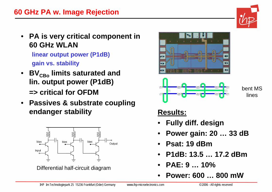
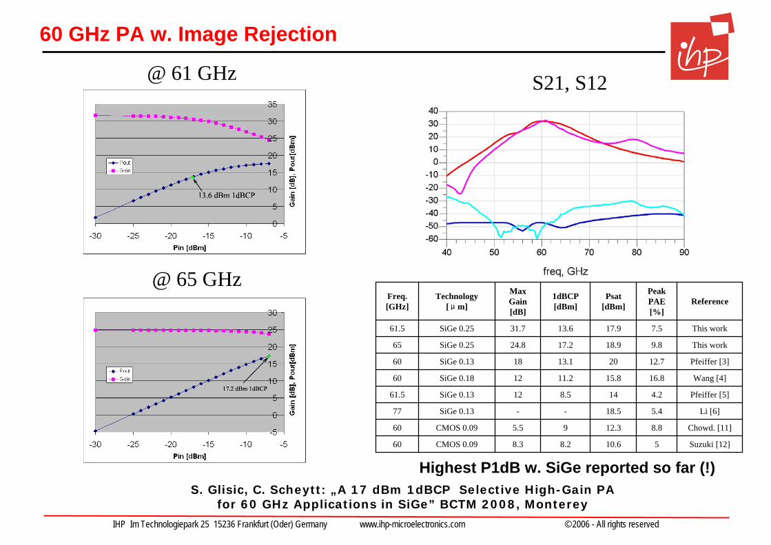
60 GHz PA w. Image Rejection
• PA is very critical component in 60 GHz WLANlinear output power (P1dB)gain vs. stability
• BVCBo limits saturated and lin. output power (P1dB) => critical for OFDM
• Passives & substrate couplingendanger stability Results:
• Fully diff. design• Power gain: 20 … 33 dB• Psat: 19 dBm• P1dB: 13.5 … 17.2 dBm• PAE: 9 … 10%• Power: 600 … 800 mW
Differential half-circuit diagram
bent MS lines
IHP Im Technologiepark 25 15236 Frankfurt (Oder) Germany www.ihp-microelectronics.com © 2006 - All rights reserved
60 GHz PA w. Image Rejection
Suzuki [12]510.68.28.3CMOS 0.0960
Chowd. [11]8.812.395.5CMOS 0.0960
Li [6]5.418.5--SiGe 0.1377
Pfeiffer [5]4.2148.512SiGe 0.1361.5
Wang [4]16.815.811.212SiGe 0.1860
Pfeiffer [3]12.72013.118SiGe 0.1360
This work9.818.917.224.8SiGe 0.2565
This work7.517.913.631.7SiGe 0.2561.5
ReferencePeak PAE [%]
Psat[dBm]
1dBCP [dBm]
Max Gain [dB]
Technology [μm]
Freq. [GHz]
Highest P1dB w. SiGe reported so far (!)
S21, S12@ 61 GHz
@ 65 GHz
S. Glisic, C. Scheytt: „A 17 dBm 1dBCP Selective High-Gain PA for 60 GHz Applications in SiGe” BCTM 2008, Monterey
IHP Im Technologiepark 25 15236 Frankfurt (Oder) Germany www.ihp-microelectronics.com © 2006 - All rights reserved
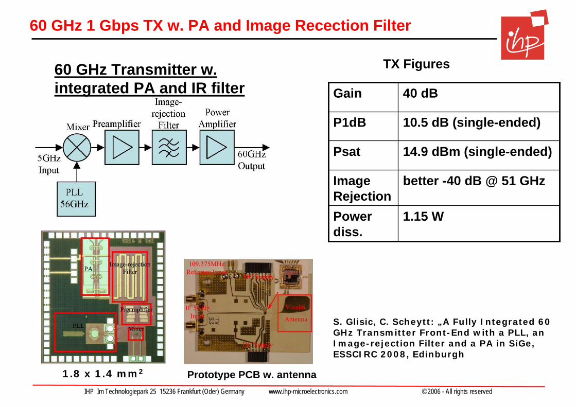
60 GHz 1 Gbps TX w. PA and Image Recection Filter
60 GHz Transmitter w. integrated PA and IR filter
14.9 dBm (single-ended)Psat
1.15 WPower diss.
better -40 dB @ 51 GHzImage Rejection
10.5 dB (single-ended)P1dB
40 dBGain
TX Figures
1.8 x 1.4 mm2
S. Glisic, C. Scheytt: „A Fully Integrated 60 GHz Transmitter Front-End with a PLL, an Image-rejection Filter and a PA in SiGe, ESSCIRC 2008, Edinburgh
Prototype PCB w. antenna
IHP Im Technologiepark 25 15236 Frankfurt (Oder) Germany www.ihp-microelectronics.com © 2006 - All rights reserved
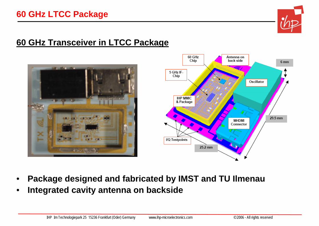
60 GHz LTCC Package
60 GHz Transceiver in LTCC Package
• Package designed and fabricated by IMST and TU Ilmenau• Integrated cavity antenna on backside
IHP Im Technologiepark 25 15236 Frankfurt (Oder) Germany www.ihp-microelectronics.com © 2006 - All rights reserved
Outline
• Silicon technology progress and mm-wave design
• 1 Gbps 60 GHz transceiver (WIGWAM, BMBF)
• 2 – 6 Gbps 60 GHz transceiver (Easy-A, BMBF)
• 94 and 122 GHz components for mm-wave sensing (ISM, ZIM)
• Towards 100 Gbps Wireless Short-Range Communications (TeraCom, Leibniz Excellence Project)
IHP Im Technologiepark 25 15236 Frankfurt (Oder) Germany www.ihp-microelectronics.com © 2006 - All rights reserved
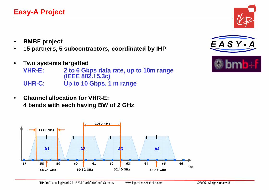
Easy-A Project
• BMBF project• 15 partners, 5 subcontractors, coordinated by IHP
• Two systems targettedVHR-E: 2 to 6 Gbps data rate, up to 10m range
(IEEE 802.15.3c)UHR-C: Up to 10 Gbps, 1 m range
• Channel allocation for VHR-E:4 bands with each having BW of 2 GHz

IHP Im Technologiepark 25 15236 Frankfurt (Oder) Germany www.ihp-microelectronics.com © 2006 - All rights reserved
Easy-A RF Frontend Architecture
• 2 GHz BW -> higher IF required• Sliding-IF transceiver (Atheros’ solution for 802.11a) chosen• 48 GHz PLL, 12 GHz IF• Image at 60GHz-24GHz = 36GHz is well suppressed by LNA / PA• 1:4 division delivers accurate quadrature signals at 12GHz
Funded by BMBF15 Partners, 5 SubcontractorsStart: 1.1.2008Co-ordinated by IHP
TX
RX
IHP Im Technologiepark 25 15236 Frankfurt (Oder) Germany www.ihp-microelectronics.com © 2006 - All rights reserved
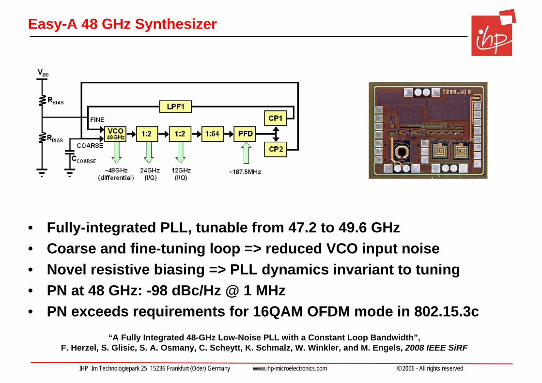
Easy-A 48 GHz Synthesizer
• Fully-integrated PLL, tunable from 47.2 to 49.6 GHz • Coarse and fine-tuning loop => reduced VCO input noise• Novel resistive biasing => PLL dynamics invariant to tuning• PN at 48 GHz: -98 dBc/Hz @ 1 MHz • PN exceeds requirements for 16QAM OFDM mode in 802.15.3c
“A Fully Integrated 48-GHz Low-Noise PLL with a Constant Loop Bandwidth”, F. Herzel, S. Glisic, S. A. Osmany, C. Scheytt, K. Schmalz, W. Winkler, and M. Engels, 2008 IEEE SiRF
IHP Im Technologiepark 25 15236 Frankfurt (Oder) Germany www.ihp-microelectronics.com © 2006 - All rights reserved
Outline
• Silicon technology progress and mm-wave design
• 1 Gbps 60 GHz transceiver (WIGWAM, BMBF)
• 2 – 6 Gbps 60 GHz transceiver (Easy-A, BMBF)
• 94 and 122 GHz components for mm-wave sensing (ISM, ZIM)
• Towards 100 Gbps Wireless Short-Range Communications (TeraCom, Leibniz Excellence Project)
IHP Im Technologiepark 25 15236 Frankfurt (Oder) Germany www.ihp-microelectronics.com © 2006 - All rights reserved
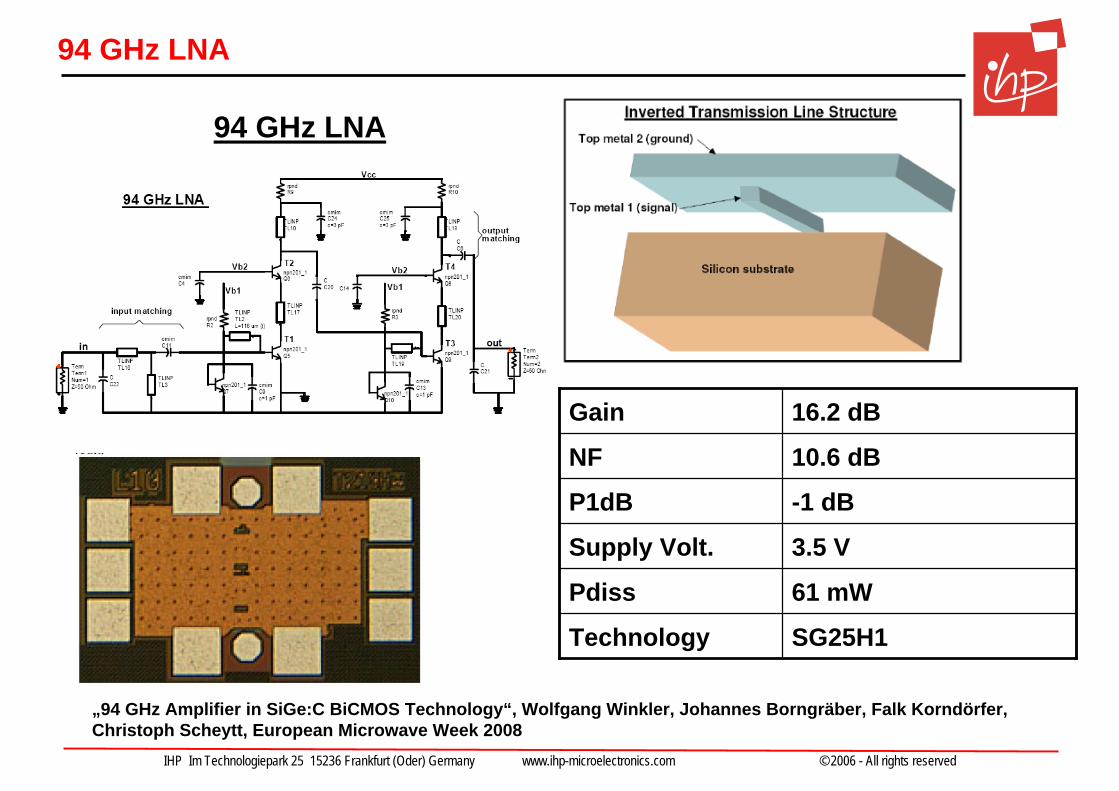
94 GHz LNA
3.5 V Supply Volt.
61 mWPdiss
SG25H1Technology
-1 dBP1dB
10.6 dBNF
16.2 dBGain
„94 GHz Amplifier in SiGe:C BiCMOS Technology“, Wolfgang Winkler, Johannes Borngräber, Falk Korndörfer, Christoph Scheytt, European Microwave Week 2008
94 GHz LNA
IHP Im Technologiepark 25 15236 Frankfurt (Oder) Germany www.ihp-microelectronics.com © 2006 - All rights reserved
122 GHz Receiver in SiGe BiCMOS
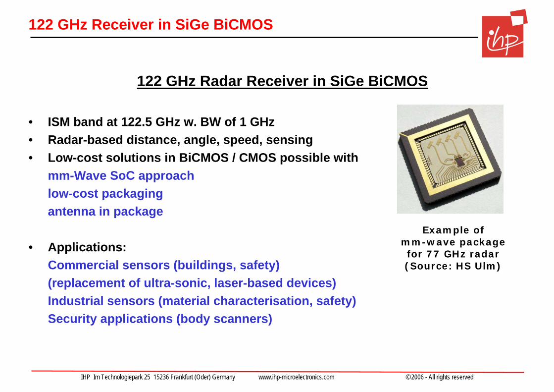
122 GHz Radar Receiver in SiGe BiCMOS
• ISM band at 122.5 GHz w. BW of 1 GHz• Radar-based distance, angle, speed, sensing• Low-cost solutions in BiCMOS / CMOS possible with
mm-Wave SoC approachlow-cost packagingantenna in package
• Applications:Commercial sensors (buildings, safety) (replacement of ultra-sonic, laser-based devices)Industrial sensors (material characterisation, safety)Security applications (body scanners)
Example of mm-wave packagefor 77 GHz radar(Source: HS Ulm)
IHP Im Technologiepark 25 15236 Frankfurt (Oder) Germany www.ihp-microelectronics.com © 2006 - All rights reserved
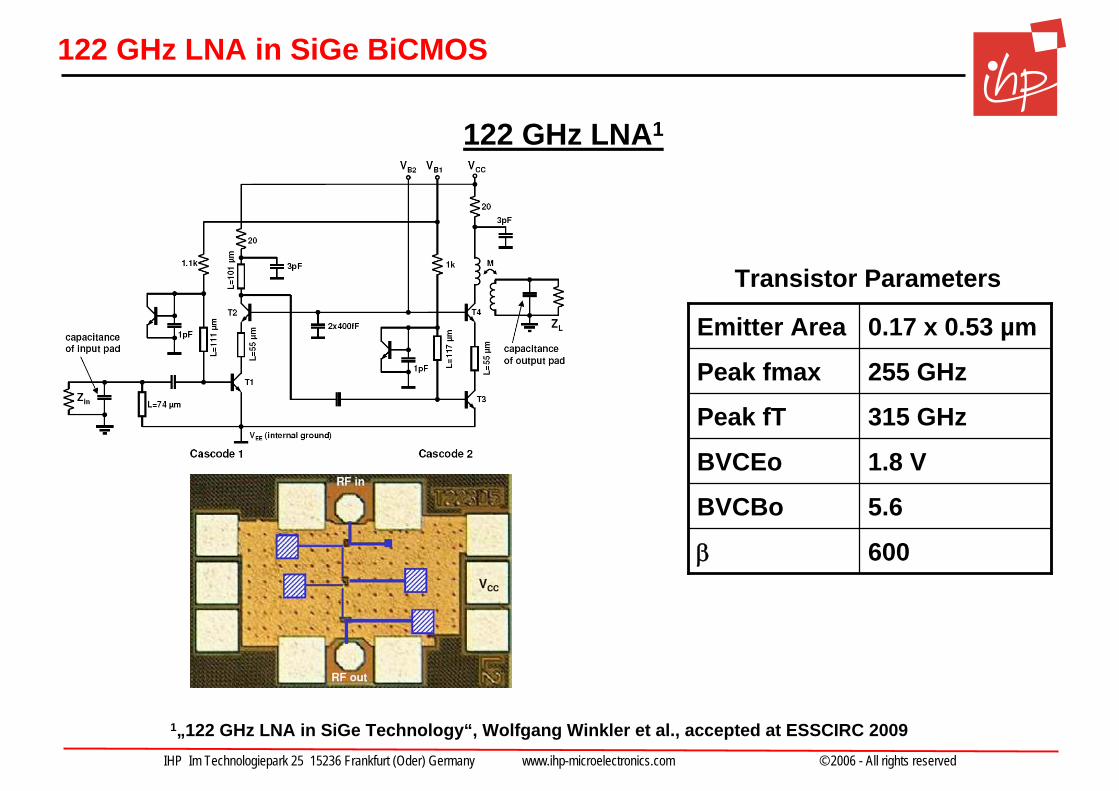
122 GHz LNA in SiGe BiCMOS
1„122 GHz LNA in SiGe Technology“, Wolfgang Winkler et al., accepted at ESSCIRC 2009
122 GHz LNA1
1.8 VBVCEo
5.6 BVCBo
600β
315 GHzPeak fT
255 GHzPeak fmax
0.17 x 0.53 µm Emitter Area
Transistor Parameters
IHP Im Technologiepark 25 15236 Frankfurt (Oder) Germany www.ihp-microelectronics.com © 2006 - All rights reserved
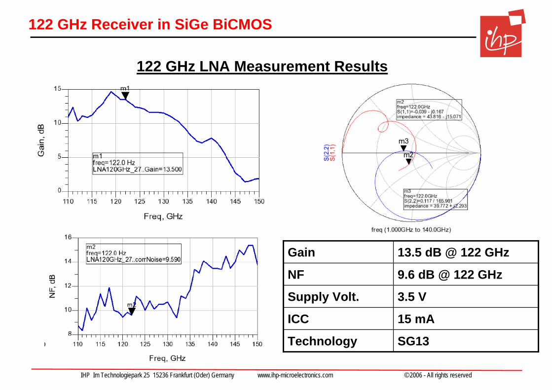
122 GHz Receiver in SiGe BiCMOS
3.5 V Supply Volt.
15 mAICC
SG13Technology
9.6 dB @ 122 GHzNF
13.5 dB @ 122 GHzGain
122 GHz LNA Measurement Results
IHP Im Technologiepark 25 15236 Frankfurt (Oder) Germany www.ihp-microelectronics.com © 2006 - All rights reserved
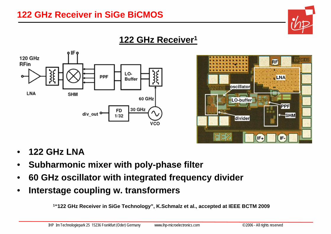
122 GHz Receiver in SiGe BiCMOS
• 122 GHz LNA• Subharmonic mixer with poly-phase filter• 60 GHz oscillator with integrated frequency divider• Interstage coupling w. transformers
1“122 GHz Receiver in SiGe Technology”, K.Schmalz et al., accepted at IEEE BCTM 2009
122 GHz Receiver1
IHP Im Technologiepark 25 15236 Frankfurt (Oder) Germany www.ihp-microelectronics.com © 2006 - All rights reserved
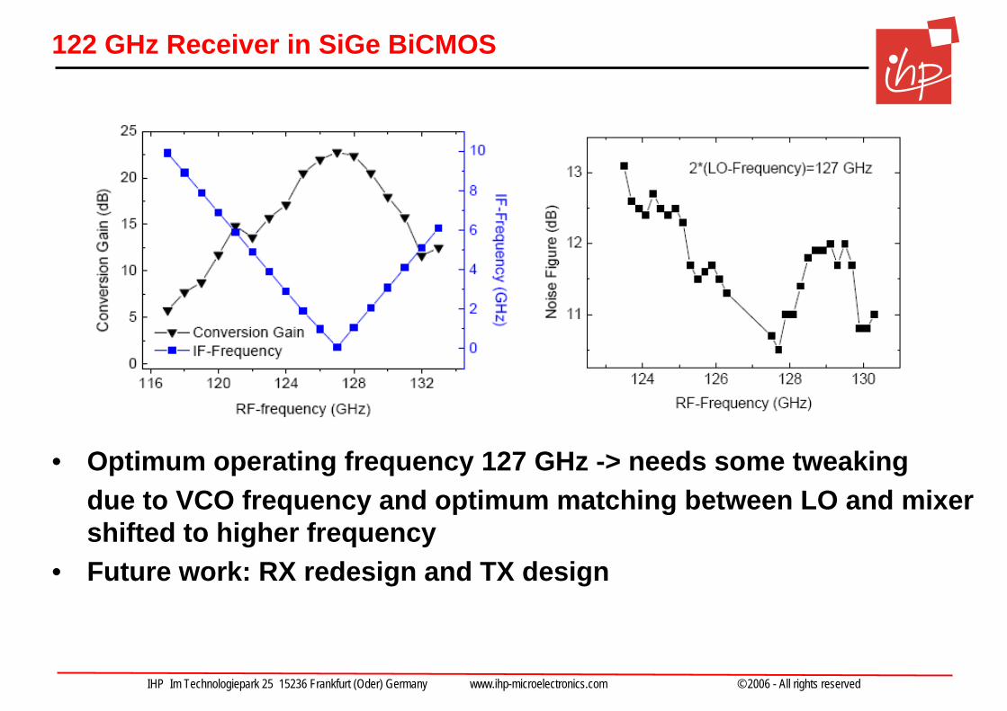
122 GHz Receiver in SiGe BiCMOS
• Optimum operating frequency 127 GHz -> needs some tweakingdue to VCO frequency and optimum matching between LO and mixershifted to higher frequency
• Future work: RX redesign and TX design
IHP Im Technologiepark 25 15236 Frankfurt (Oder) Germany www.ihp-microelectronics.com © 2006 - All rights reserved
Outline
• Silicon technology progress and mm-wave design
• 1 Gbps 60 GHz transceiver (WIGWAM, BMBF)
• 2 – 6 Gbps 60 GHz transceiver (Easy-A, BMBF)
• 94 and 122 GHz components for mm-wave sensing (ISM, ZIM)
• Towards 100 Gbps Wireless Short-Range Communications (TeraCom, Leibniz Excellence Project)
IHP Im Technologiepark 25 15236 Frankfurt (Oder) Germany www.ihp-microelectronics.com © 2006 - All rights reserved
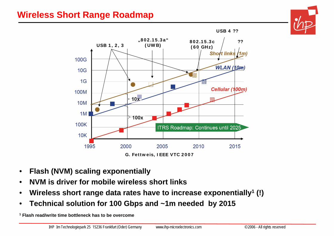
Wireless Short Range Roadmap
• Flash (NVM) scaling exponentially• NVM is driver for mobile wireless short links• Wireless short range data rates have to increase exponentially1 (!)• Technical solution for 100 Gbps and ~1m needed by 2015 1 Flash read/write time bottleneck has to be overcome
USB 1, 2, 3„802.15.3a“
(UWB)802.15.3c(60 GHz)
??
G. Fettweis, IEEE VTC 2007
USB 4 ??
IHP Im Technologiepark 25 15236 Frankfurt (Oder) Germany www.ihp-microelectronics.com © 2006 - All rights reserved
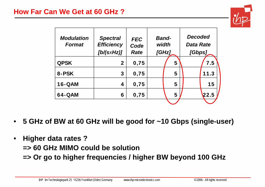
How Far Can We Get at 60 GHz ?
• 5 GHz of BW at 60 GHz will be good for ~10 Gbps (single-user)
• Higher data rates ?=> 60 GHz MIMO could be solution=> Or go to higher frequencies / higher BW beyond 100 GHz
22.550,75664-QAM
1550,75416-QAM
11.350,7538-PSK
7.550,752QPSK
DecodedData Rate
[Gbps]
Band-width[GHz]
FEC Code Rate
SpectralEfficiency[b/(sxHz)]
Modulation Format
IHP Im Technologiepark 25 15236 Frankfurt (Oder) Germany www.ihp-microelectronics.com © 2006 - All rights reserved
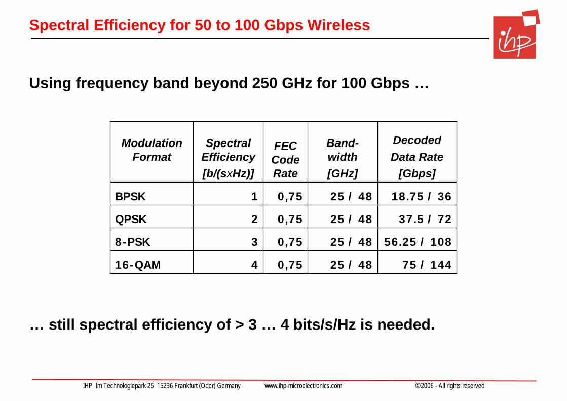
Spectral Efficiency for 50 to 100 Gbps Wireless
18.75 / 36 25 / 480,751BPSK
37.5 / 7225 / 480,752QPSK
56.25 / 10825 / 480,7538-PSK
75 / 14425 / 480,75416-QAM
DecodedData Rate
[Gbps]
Band-width[GHz]
FEC Code Rate
SpectralEfficiency[b/(sxHz)]
Modulation Format
Using frequency band beyond 250 GHz for 100 Gbps …
… still spectral efficiency of > 3 … 4 bits/s/Hz is needed.
IHP Im Technologiepark 25 15236 Frankfurt (Oder) Germany www.ihp-microelectronics.com © 2006 - All rights reserved
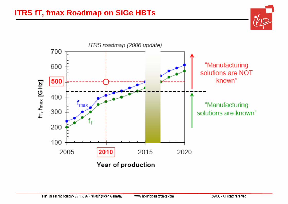
ITRS fT, fmax Roadmap on SiGe HBTs
IHP Im Technologiepark 25 15236 Frankfurt (Oder) Germany www.ihp-microelectronics.com © 2006 - All rights reserved
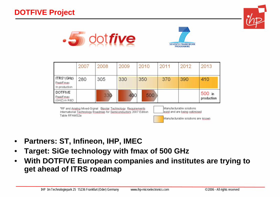
DOTFIVE Project
• Partners: ST, Infineon, IHP, IMEC• Target: SiGe technology with fmax of 500 GHz• With DOTFIVE European companies and institutes are trying to
get ahead of ITRS roadmap
IHP Im Technologiepark 25 15236 Frankfurt (Oder) Germany www.ihp-microelectronics.com © 2006 - All rights reserved
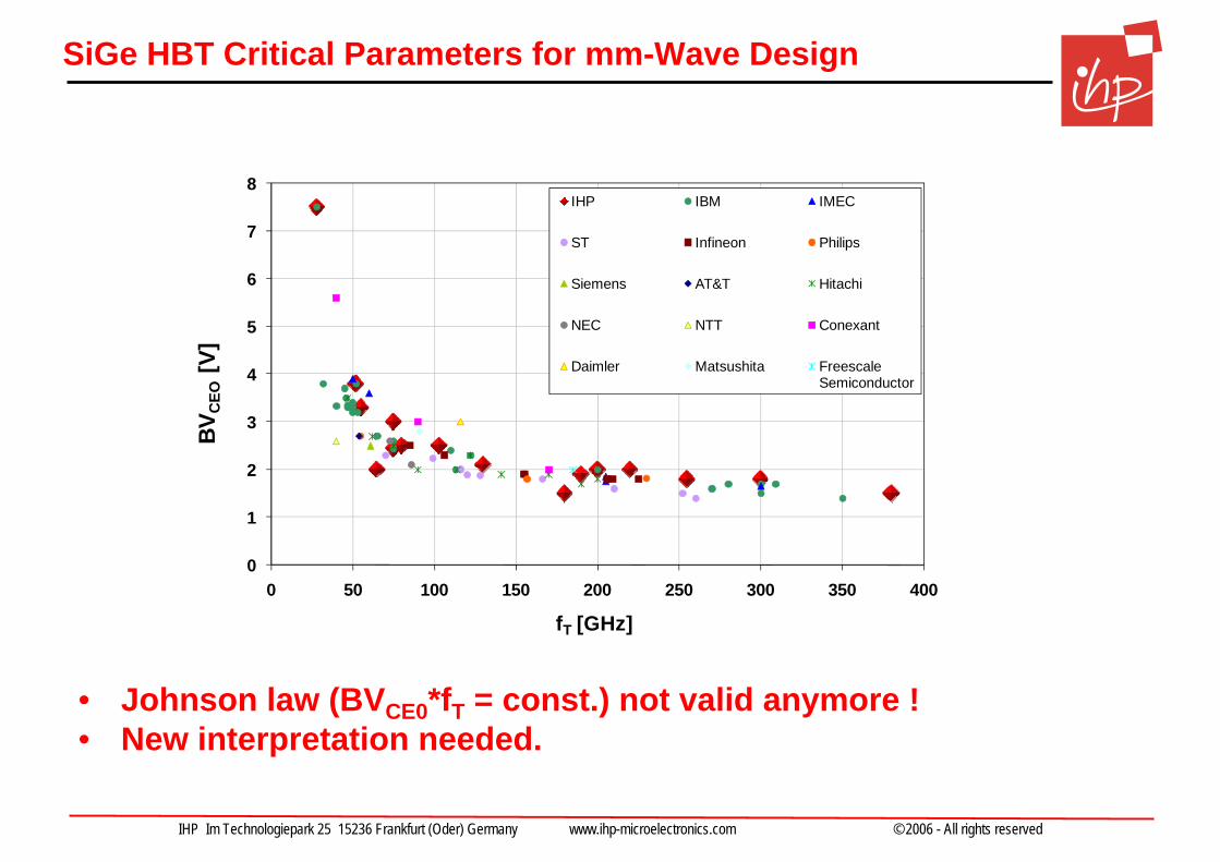
SiGe HBT Critical Parameters for mm-Wave Design
0
1
2
3
4
5
6
7
8
0 50 100 150 200 250 300 350 400
BVC
EO[V
]
fT [GHz]
IHP IBM IMEC
ST Infineon Philips
Siemens AT&T Hitachi
NEC NTT Conexant
Daimler Matsushita FreescaleSemiconductor
• Johnson law (BVCE0*fT = const.) not valid anymore ! • New interpretation needed.
IHP Im Technologiepark 25 15236 Frankfurt (Oder) Germany www.ihp-microelectronics.com © 2006 - All rights reserved
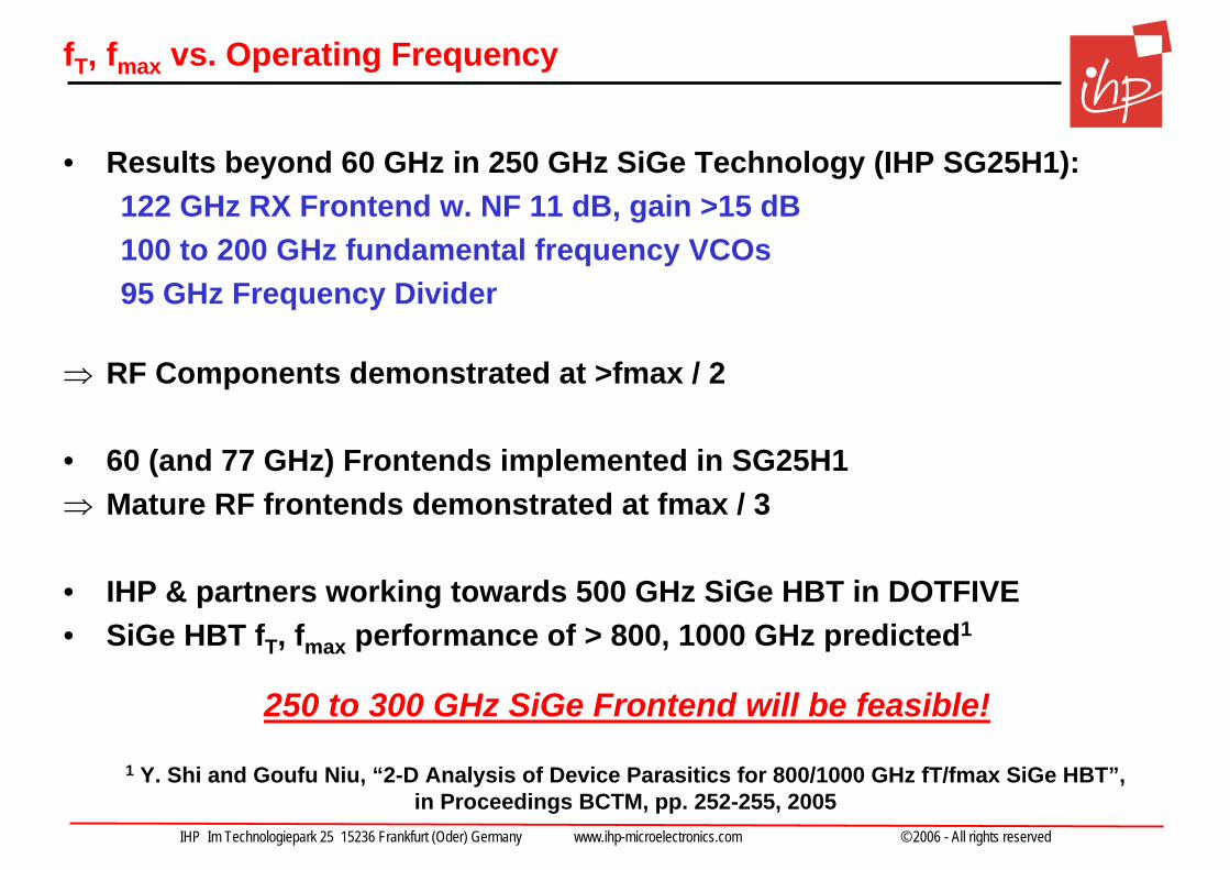
fT, fmax vs. Operating Frequency
• Results beyond 60 GHz in 250 GHz SiGe Technology (IHP SG25H1):122 GHz RX Frontend w. NF 11 dB, gain >15 dB100 to 200 GHz fundamental frequency VCOs95 GHz Frequency Divider
⇒ RF Components demonstrated at >fmax / 2
• 60 (and 77 GHz) Frontends implemented in SG25H1⇒ Mature RF frontends demonstrated at fmax / 3
• IHP & partners working towards 500 GHz SiGe HBT in DOTFIVE • SiGe HBT fT, fmax performance of > 800, 1000 GHz predicted1
250 to 300 GHz SiGe Frontend will be feasible!
1 Y. Shi and Goufu Niu, “2-D Analysis of Device Parasitics for 800/1000 GHz fT/fmax SiGe HBT”, in Proceedings BCTM, pp. 252-255, 2005
IHP Im Technologiepark 25 15236 Frankfurt (Oder) Germany www.ihp-microelectronics.com © 2006 - All rights reserved
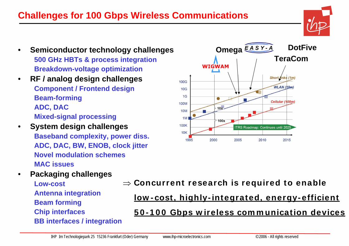
Challenges for 100 Gbps Wireless Communications
• Semiconductor technology challenges500 GHz HBTs & process integrationBreakdown-voltage optimization
• RF / analog design challengesComponent / Frontend designBeam-formingADC, DACMixed-signal processing
• System design challengesBaseband complexity, power diss. ADC, DAC, BW, ENOB, clock jitterNovel modulation schemesMAC issues
• Packaging challengesLow-costAntenna integrationBeam formingChip interfacesBB interfaces / integration
OmegaTeraCom
⇒ Concurrent research is required to enable
low-cost, highly-integrated, energy-efficient
50-100 Gbps wireless communication devices
DotFive
IHP Im Technologiepark 25 15236 Frankfurt (Oder) Germany www.ihp-microelectronics.com © 2006 - All rights reserved
Conclusion
• 60 GHz band offers BW for up to 10 Gbps wireless short-rangecommunication or more.
• SiGe BiCMOS (and CMOS) technology very well suited for 60 GHz wireless communication frontends.
• 50 to 100 Gbps wireless short-range communication is driven byNVM capacity and high-resolution media applications
• Beyond 250 GHz abundant BW is available which could be usedfor wireless short-range communication.
• Silicon technology will enable low-cost single-chip RF frontendsfor such applications
IHP Im Technologiepark 25 15236 Frankfurt (Oder) Germany www.ihp-microelectronics.com © 2006 - All rights reserved
Acknowledgements
• Thanks to:
IHP circuit design dept., specificallyYaoming Sun, Frank Herzel, Srdjan Glisic, Klaus Schmalz, Chang-Soon Choi, Johannes Borngräber
IHP system design dept.IHP technology dept.BMBF for funding of Wigwam / Easy-A project
…
today‘s audience!