Embed Size (px)
Citation preview
Service Manual
DEALER: Keep this manual. The
procedures in this manual MUST be
performed by a qualified technician.
For more information regarding
Invacare products, parts, and services,
please visit www.invacare.com
MK5™NX™Electronics
NX
NX-B
NX-LP
NX-75
NX w/ACC
USEFUL TERMS
MK5™
NX™
Electronics 2 Part No 1110532
� WARNING
A QUALIFIED TECHNICIAN MUST PERFORM THE INITIAL SET UP
OF THIS WHEELCHAIR. ALSO, A QUALIFIED TECHNICIAN MUST
PERFORM ALL PROCEDURES IN THE SERVICE MANUAL.
WHEELCHAIR USERS: DO NOT SERVICE OR OPERATE THIS
EQUIPMENT WITHOUT FIRST READING AND UNDERSTANDING
(1) THE OWNER’S OPERATOR AND MAINTENANCE MANUAL
AND (2) THE SEATING SYSTEM MANUAL (IF APPLICABLE). IF
YOU ARE UNABLE TO UNDERSTAND THE WARNINGS,
CAUTIONS, AND INSTRUCTIONS, CONTACT INVACARE
TECHNICAL SUPPORT BEFORE ATTEMPTING TO SERVICE OR
OPERATE THIS EQUIPMENT - OTHERWISE INJURY OR DAMAGE
MAY RESULT.
DEALERS AND QUALIFIED TECHNICIANS: DO NOT SERVICE OR
OPERATE THIS EQUIPMENT WITHOUT FIRST READING AND
UNDERSTANDING (1) THE OWNER’S OPERATOR AND
MAINTENANCE MANUAL, (2) THE SERVICE MANUAL (IF
APPLICABLE) AND (3) THE SEATING SYSTEM MANUAL (IF
APPLICABLE). IF YOU ARE UNABLE TO UNDERSTAND THE
WARNINGS, CAUTIONS AND INSTRUCTIONS, CONTACT
INVACARE TECHNICAL SUPPORT BEFORE ATTEMPTING TO
SERVICE OR OPERATE THIS EQUIPMENT - OTHERWISE, INJURY
OR DAMAGE MAY RESULT.
USEFUL TERMSThe following acronyms are used throughout this manual:
ACRONYM DEFINITION
SPJ Single Purpose Joystick
CSPJ Composite Single Purpose Joystick
ACC Accessory
NX Non-Expandable
NX-LP Non-Expandable Limited Programming
NX-B Non-Expandable with Alternate Standard Program
NX-75 Non-Expandable with 75 Amps
RWD Rear Wheel Drive
CWD Center Wheel Drive
DCI Drive Control Input
NOTE: Updated versions of this manual are available on www.invacare.com.

TABLE OF CONTENTS
TABLE OF CONTENTS
USEFUL TERMS ................................................................................. 2SPECIAL NOTES ................................................................................ 5
SECTION 1—GENERAL GUIDELINES ................................................... 6
Controller Settings/Repair or Service ...................................................................................................6
Operation Information ..............................................................................................................................6
SECTION 2—EMI INFORMATION ....................................................... 7
SECTION 3—TROUBLESHOOTING ...................................................... 9
All Power Wheelchairs .............................................................................................................................9
Wheelchairs With Elevate Systems......................................................................................................10
SECTION 4—JOYSTICK DESCRIPTIONS ............................................. 11
SPJ™and CSPJ™Joystick Switches and Indicators ............................................................................11
On/Off Switch.......................................................................................................................................11
SPJ Joysticks .....................................................................................................................................11
CSPJ Joysticks ..................................................................................................................................11
Speed Control Knob ...........................................................................................................................12
Joystick....................................................................................................................................................12
Charger/Programming Input..............................................................................................................12
Information Gauge Display ................................................................................................................12
SPJ+ and SPJ+ w/ACC Joystick Switches and Indicators .................................................................15
On/Off Button ......................................................................................................................................16
Speedometer.........................................................................................................................................16
Speed Control Buttons.......................................................................................................................16
Mode Button .........................................................................................................................................16
Joystick....................................................................................................................................................17
Charger/Programming Input..............................................................................................................17
Service Indicator...................................................................................................................................17
Information Gauge Display ................................................................................................................17
SECTION 5—REMOTE PROGRAMMER .............................................. 19
Overview....................................................................................................................................................19
Remote Programmer Terminology ......................................................................................................20
Function..................................................................................................................................................20
Value .......................................................................................................................................................20
Program (Preset Programs with Standard Value Settings) .........................................................20
Temporary Memory............................................................................................................................20
User Memory Values...........................................................................................................................20
Description Of Remote Programmer Keys .......................................................................................21
Part No 1110532 3 MK5™
NX™
Electronics

TABLE OF CONTENTS
TABLE OF CONTENTS
SECTION 6—PERFORMANCE ADJUSTMENTS .................................... 22Main Menu..................................................................................................................................................22
Performance Adjust Menu......................................................................................................................22
MK5 NX, MK5 NX-75, MK5 NX w/ACC and MK5 NX-B.......................................................22
MK5 NX-LP...........................................................................................................................................23
Making Performance Adjustments........................................................................................................23
MK5 NX, MK5 NX-75, MK5 NX w/ACC, and MK5 NX-B Controller.................................25
Flowchart .........................................................................................................................................25
Performance Menu Description .................................................................................................26
MK5 NX-LP Controller......................................................................................................................27
Flowchart .........................................................................................................................................27
Performance Menu Description .................................................................................................28
SECTION 7—PROGRAMS ................................................................. 29
Program Settings.......................................................................................................................................29
SECTION 8—OTHER FUNCTIONS ..................................................... 32
Description of Other Functions............................................................................................................32
SECTION 9—DIAGNOSTIC CODES .................................................... 33
What Are Diagnostics Codes? ..............................................................................................................33
SECTION 10—CONNECTOR DESCRIPTIONS ...................................... 36
Controller Connector Descriptions....................................................................................................36
MK5 NX, NX-75, NX-B and NX-LP...............................................................................................36
MK5 NX w/ACC .................................................................................................................................36
Battery Connector Pinout .................................................................................................................37
Motor Connector Pinout...................................................................................................................37
Joystick Connector Pinout.................................................................................................................37
Drive Control Input (DCI) ................................................................................................................37
DCI Connector Pinout for MK5 NX, MK5 NX-75, MK5 NX-B, and NX-LP .................38
DCI Connector Pinout for MK5 NX w/ACC .........................................................................38
Battery Charger Port ..........................................................................................................................38
LIMITED WARRANTY ..................................................................... 39
MK5™
NX™
Electronics 4 Part No 1110532
SPECIAL NOTES
Part No 1110532 5 MK5™
NX™
Electronics
SPECIAL NOTESSignal words are used in this manual and apply to hazards or unsafe practices which could result in personal injury or property damage. Refer to the table below for definitions of the signal words.
NOTICE
THE INFORMATION CONTAINED IN THIS DOCUMENT IS SUBJECT TO
CHANGE WITHOUT NOTICE.
� REPAIR OR SERVICE WARNING
Setup of the Electronic Controller is to be performed only by a qualified technician.
The adjustments of the controller may affect other activities of the wheelchair.
Damage to the equipment could occur under these circumstances.
� OPERATION WARNING
Performance adjustments should only be made by professionals of the health care
field or persons fully conversant with this process and the driver's capabilities.
Incorrect settings could cause injury to the driver, bystanders, damage to the
wheelchair and surrounding property. After the wheelchair has been setup, check to
make sure that the wheelchair performs to the specifications entered in the setup
procedure. If the wheelchair does not perform to specifications, turn the wheelchair
off immediately and re-enter setup specifications. Repeat this procedure until the
wheelchair performs to specifications.
� WARNING
Invacare products are specifically designed and manufactured for use in conjunction
with Invacare accessories. Accessories designed by other manufacturers have not
been tested by Invacare and are not recommended for use with Invacare products.
SIGNAL WORD MEANING
WARNING
Warning indicates a potentially hazardous situation which, if not avoided,
could result in death or serious injury.
CAUTION
Caution indicates a potentially hazardous situation which, if not avoided,
may result in property damage.

SECTION 1—GENERAL GUIDELINES
MK5™
NX™
Electronics 6 Part No 1110532
SECTION 1—GENERAL GUIDELINES
� WARNING
SECTION 1 - GENERAL GUIDELINES contains important information for the safe
operation and use of this product. DO NOT use this product or any available
optional equipment without first completely reading and understanding these
instructions and any additional instructional material such as Owner’s Manuals,
Service Manuals or Instruction Sheets supplied with this product or optional
equipment. If you are unable to understand the Warnings, Cautions or Instructions,
contact a healthcare professional, dealer or technical personnel before attempting
to use this equipment - otherwise, injury or damage may occur.
Controller Settings/Repair or Service
Set-up of the Electronic Control Unit is to be performed only by a qualified technician. The final adjustments of the controller may affect other activities of the wheelchair. Reprogramming the controller reduces the stability/control of the wheelchair. Other program settings could cause the wheelchair to tip over resulting in serious injury to the user and/or damage to the surrounding property.
Operation Information
After the wheelchair has been set-up, check to make sure that the wheelchair performs to the specifications entered during the set-up procedure. If the wheelchair does not perform to specifications, turn the wheelchair off immediately and reenter set-up specifications. Repeat this procedure until the wheelchair performs to specifications.
Invacare products are specifically designed and manufactured for use in conjunction with Invacare accessories. Accessories designed by other manufacturers have not been tested by Invacare and are not recommended for use with Invacare products.
DO NOT use the wheelchair if the joystick boot is torn or cracked. If the joystick boot becomes torn or cracked, replace IMMEDIATELY.
If the joystick knob is missing, DO NOT use the wheelchair. In case of a fall, the exposed stem could cause serious personal injury.
Periodically inspect the joystick and joystick cable for damage. Joystick cable MUST be routed and secured properly to ensure that cable does not become entangled and damaged/pinched during normal operation of wheelchair. If the joystick and/or cable is damaged, DO NOT use the wheelchair.
If the joystick knob does not return back to the neutral position, DO NOT use the wheelchair.
SECTION 2—EMI INFORMATION
SECTION 2—EMI INFORMATION
� WARNING
CAUTION: IT IS VERY IMPORTANT THAT YOU READ THIS INFORMATION
REGARDING THE POSSIBLE EFFECTS OF ELECTROMAGNETIC
INTERFERENCE ON YOUR POWERED WHEELCHAIR.
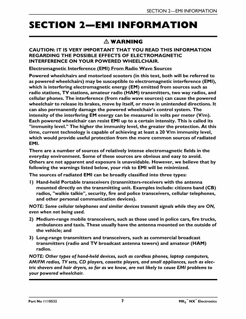
Electromagnetic Interference (EMI) From Radio Wave Sources
Powered wheelchairs and motorized scooters (in this text, both will be referred to
as powered wheelchairs) may be susceptible to electromagnetic interference (EMI),
which is interfering electromagnetic energy (EM) emitted from sources such as
radio stations, TV stations, amateur radio (HAM) transmitters, two way radios, and
cellular phones. The interference (from radio wave sources) can cause the powered
wheelchair to release its brakes, move by itself, or move in unintended directions. It
can also permanently damage the powered wheelchair's control system. The
intensity of the interfering EM energy can be measured in volts per meter (V/m).
Each powered wheelchair can resist EMI up to a certain intensity. This is called its
"immunity level." The higher the immunity level, the greater the protection. At this
time, current technology is capable of achieving at least a 20 V/m immunity level,
which would provide useful protection from the more common sources of radiated
EMI.
There are a number of sources of relatively intense electromagnetic fields in the
everyday environment. Some of these sources are obvious and easy to avoid.
Others are not apparent and exposure is unavoidable. However, we believe that by
following the warnings listed below, your risk to EMI will be minimized.
The sources of radiated EMI can be broadly classified into three types:
1) Hand-held Portable transceivers (transmitters-receivers with the antenna
mounted directly on the transmitting unit. Examples include: citizens band (CB)
radios, "walkie talkie", security, fire and police transceivers, cellular telephones,
and other personal communication devices).
NOTE: Some cellular telephones and similar devices transmit signals while they are ON,
even when not being used.
2) Medium-range mobile transceivers, such as those used in police cars, fire trucks,
ambulances and taxis. These usually have the antenna mounted on the outside of
the vehicle; and
3) Long-range transmitters and transceivers, such as commercial broadcast
transmitters (radio and TV broadcast antenna towers) and amateur (HAM)
radios.
NOTE: Other types of hand-held devices, such as cordless phones, laptop computers,
AM/FM radios, TV sets, CD players, cassette players, and small appliances, such as elec-
tric shavers and hair dryers, so far as we know, are not likely to cause EMI problems to
your powered wheelchair.
Part No 1110532 7 MK5™
NX™
Electronics

SECTION 2—EMI INFORMATION
� WARNING
Powered Wheelchair Electromagnetic Interference (EMI)
Because EM energy rapidly becomes more intense as one moves closer to the
transmitting antenna (source), the EM fields from hand-held radio wave sources
(transceivers) are of special concern. It is possible to unintentionally bring high
levels of EM energy very close to the powered wheelchair's control system while
using these devices. This can affect powered wheelchair movement and braking.
Therefore, the warnings listed below are recommended to prevent possible
interference with the control system of the powered wheelchair.
Electromagnetic interference (EMI) from sources such as radio and TV stations,
amateur radio (HAM) transmitters, two-way radios, and cellular phones can affect
powered wheelchairs and motorized scooters.
FOLLOWING THE WARNINGS LISTED BELOW SHOULD REDUCE THE
CHANCE OF UNINTENDED BRAKE RELEASE OR POWERED WHEELCHAIR
MOVEMENT WHICH COULD RESULT IN SERIOUS INJURY.
1) Do not operate hand-held transceivers (transmitters receivers), such as citizens
band (CB) radios, or turn ON personal communication devices, such as cellular
phones, while the powered wheelchair is turned ON;
2) Be aware of nearby transmitters, such as radio or TV stations, and try to avoid
coming close to them;
3) If unintended movement or brake release occurs, turn the powered wheelchair
OFF as soon as it is safe;
4) Be aware that adding accessories or components, or modifying the powered
wheelchair, may make it more susceptible to EMI (NOTE: There is no easy way
to evaluate their effect on the overall immunity of the powered wheelchair); and
5) Report all incidents of unintended movement or brake release to the powered
wheelchair manufacturer, and note whether there is a source of EMI nearby.
Important Information
1) 20 volts per meter (V/m) is a generally achievable and useful immunity level
against EMI (as of May 1994) (the higher the level, the greater the protection);
2) The immunity level of the product is unknown.
Modification of any kind to the electronics of this wheelchair as manufactured by
Invacare may adversely affect the RFI immunity levels.
MK5™
NX™
Electronics 8 Part No 1110532

SECTION 3—TROUBLESHOOTING
SECTION 3—TROUBLESHOOTING
All Power Wheelchairs
SYMPTOM PROBABLE CAUSE SOLUTIONS
Error Code E03 or E04,
3 or 4 flashes of joystick
LEDs.
Motor lock levers disengaged. Engage motor lock levers. Refer to the wheelchair
Owner’s Manual for more information.
Bad motor connection. Check all motor connections.
Ohm out motors. Check brushes and replace if
necessary. Replace motors if high reading is present.
Normal reading is 0.2-5 Ohms (4 Pole motors) or
0.5-5 Ohms (2 Pole motors). Refer to wheelchair
Service Manual.
Bad brake coil Ohm out brake connection. Normal reading is 40-
80 Ohms.
Error Code E02, 2 flashes
of joystick LEDs.
Batteries need to be charged. Charge batteries. Refer to the wheelchair Owner’s
Manual for charging instructions.
Joystick erratic or does
not respond as desired.
Damaged motor coupling. Contact Dealer/Invacare for Service.
Electrical malfunction. Contact Dealer/Invacare for Service.
Controller programmed
improperly.
Contact Dealer/Invacare to have controller
reprogrammed.
Wheelchair veers to the
left or right when driving
on level surface.
Joystick needs to be calibrated. Calibrate joystick with programmer. If this does not
work, replace joystick. Refer to Joystick Throw on
page 32 for calibration information.
No LED’s on joystick. Joystick connection to
controller unplugged or
damaged.
Check all joystick connections. Refer to wheelchair
Owner’s Manual. If damage is found, replace
joystick.
Corroded wiring or
connections.
Possible water, salt, or urine
damage.
Replace wiring harness. Refer to wheelchair
Owner’s Manual.
Wheelchair does not
respond to commands.
Poor battery terminal
connection.
Have clean terminals. Refer to wheelchair Owner’s
Manual.
Bad joystick connection. Check all joystick connections. Refer to wheelchair
Owner’s Manual.
Bad wiring harness connection
or blown fuse.
Replace wiring harness. Refer to wheelchair
Owner’s Manual.
Battery charger connected to
joystick.
Unplug battery charger.
Power indicator off - even
after recharging.
Electrical malfunction. Contact Invacare.
Part No 1110532 9 MK5™
NX™
Electronics
SECTION 3—TROUBLESHOOTING
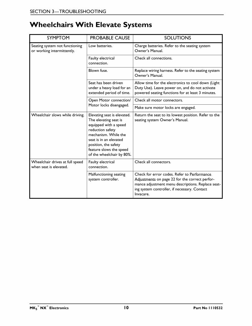
Wheelchairs With Elevate Systems
SYMPTOM PROBABLE CAUSE SOLUTIONS
Seating system not functioning
or working intermittently.
Low batteries. Charge batteries. Refer to the seating system
Owner’s Manual.
Faulty electrical
connection.
Check all connections.
Blown fuse. Replace wiring harness. Refer to the seating system
Owner’s Manual.
Seat has been driven
under a heavy load for an
extended period of time.
Allow time for the electronics to cool down (Light
Duty Use). Leave power on, and do not activate
powered seating functions for at least 3 minutes.
Open Motor connection/
Motor locks disengaged.
Check all motor connectors.
Make sure motor locks are engaged.
Wheelchair slows while driving. Elevating seat is elevated.
The elevating seat is
equipped with a speed
reduction safety
mechanism. While the
seat is in an elevated
position, the safety
feature slows the speed
of the wheelchair by 80%.
Return the seat to its lowest position. Refer to the
seating system Owner’s Manual.
Wheelchair drives at full speed
when seat is elevated.
Faulty electrical
connection.
Check all connectors.
Malfunctioning seating
system controller.
Check for error codes. Refer to Performance
Adjustments on page 22 for the correct perfor-
mance adjustment menu descriptions. Replace seat-
ing system controller, if necessary. Contact
Invacare.
MK5™
NX™
Electronics 10 Part No 1110532

SECTION 4—JOYSTICK DESCRIPTIONS
SECTION 4—JOYSTICK
DESCRIPTIONS
SPJ™and CSPJ™Joystick Switches and Indicators
NOTE: For the following information, refer to FIGURE 4.1.
FIGURE 4.1 SPJ™and CSPJ™Joystick Switches and Indicators
On/Off Switch
SPJ Joysticks
This toggle switch is located at the rear of the joystick housing.
CSPJ Joysticks
This button is located on top of the joystick housing at the rear of the joystick.
Joystick
Speed Control Knob
On/Off
Toggle Switch
Charger/
Programming Input
To Controller
JoystickInformation
Gauge On/Off
Button
To Controller
Multi-Function
Charger Port
Horn
Speed
Control Knob
CSPJ Joystick
SPJ Joystick
Part No 1110532 11 MK5™
NX™
Electronics

SECTION 4—JOYSTICK DESCRIPTIONS
Speed Control Knob
The speed control knob is located on the back of the joystick housing. This rotary switch is used for controlling the speed and acceleration of the wheelchair.
1. Turn the switch clockwise to increase the speed of the wheelchair.
2. Turn the switch counterclockwise to decrease the speed of the wheelchair.
Joystick
The joystick has proportional drive control, meaning that further the joystick is pushed from the upright (neutral) position, the faster the wheelchair moves. Your top speed, however, is limited by the setting of the speed-control knob and programmed settings.
To slow the wheelchair to a stop, simply release the joystick. The wheelchair has automatic speed and direction compensation to minimize corrections.
Charger/Programming Input
Located at the front of the joystick housing. This provides easy access for charging the wheelchair batteries. This port also serves as the Remote Programmer Communication connection.
Information Gauge Display
The Information Gauge Display is located on the front of the joystick housing. It provides the following information to the user on the status of the wheelchair -
1. Power is on.
2. True state-of-battery-charge, including notification of when the battery requires charging:
A. GREEN LED is lit, indicating well charged batteries.
B. Only AMBER LEDs are lit, indicating batteries are moderately charged. Recharge batteries before taking a long trip.
C. Only RED LED is lit, indicating batteries are running out of charge. Recharge batteries as soon as possible.
3. Program, inhibit or charge modes.
4. Fault indication (Flash Codes).
The Information Gauge display also serves as a system diagnostic device when a fault is detected by the control module. A specific number of flashes of the LEDs indicate the type of fault detected. Refer to the following table of the diagnostic indications of the wheelchair status.
MK5™
NX™
Electronics 12 Part No 1110532

SECTION 4—JOYSTICK DESCRIPTIONS
SPJ Diagnostic Indications of Wheelchair Status
DISPLAY DESCRIPTION DEFINITION COMMENTS
All three (3) LEDs are off. Power is Off.
All three (3) LEDs are on. Power is On. Fewer than three (3)
LEDs on implies reduced
battery charge.
RED LED is flashing. Battery charge is low. The batteries should be
charged as soon as possi-
ble.
Left to Right “chase” alter-
nating with steady display.
Joystick is in program-
ming, inhibit and/or charg-
ing mode.
The steady LEDs indicate
the current state of the
battery charge.
GREEN LED is flashing. Joystick is in Speed Limit
mode.
The current state of bat-
tery charge will be dis-
played at the same time.
All LEDs are flashing slowly. Joystick has detected Out-
of-Neutral-at-Power-Up
mode.
Release the joystick back
to Neutral.
All LEDs are flashing
quickly.
Joystick has detected a
fault.
Joystick uses Flash codes
to indicate faults.
INVACARE
INVACARE
INVACARE
INVACARE
INVACARE
INVACARE
INVACARE
Part No 1110532 13 MK5™
NX™
Electronics
SECTION 4—JOYSTICK DESCRIPTIONS
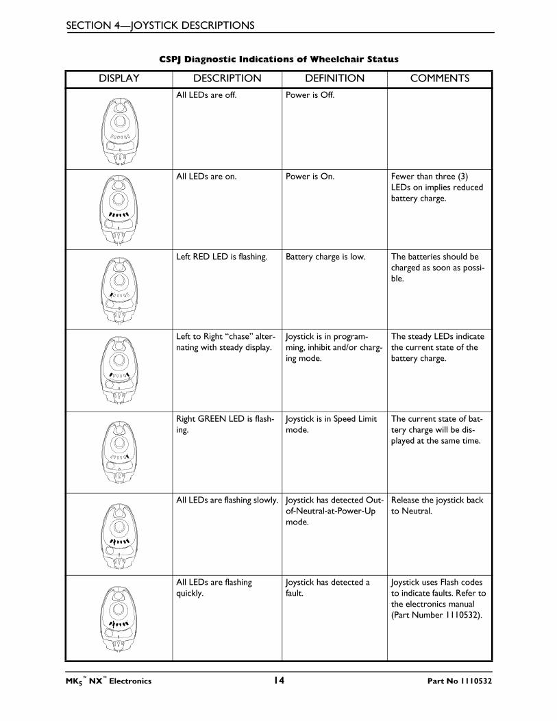
CSPJ Diagnostic Indications of Wheelchair Status
DISPLAY DESCRIPTION DEFINITION COMMENTS
All LEDs are off. Power is Off.
All LEDs are on. Power is On. Fewer than three (3)
LEDs on implies reduced
battery charge.
Left RED LED is flashing. Battery charge is low. The batteries should be
charged as soon as possi-
ble.
Left to Right “chase” alter-
nating with steady display.
Joystick is in program-
ming, inhibit and/or charg-
ing mode.
The steady LEDs indicate
the current state of the
battery charge.
Right GREEN LED is flash-
ing.
Joystick is in Speed Limit
mode.
The current state of bat-
tery charge will be dis-
played at the same time.
All LEDs are flashing slowly. Joystick has detected Out-
of-Neutral-at-Power-Up
mode.
Release the joystick back
to Neutral.
All LEDs are flashing
quickly.
Joystick has detected a
fault.
Joystick uses Flash codes
to indicate faults. Refer to
the electronics manual
(Part Number 1110532).
MK5™
NX™
Electronics 14 Part No 1110532
SECTION 4—JOYSTICK DESCRIPTIONS
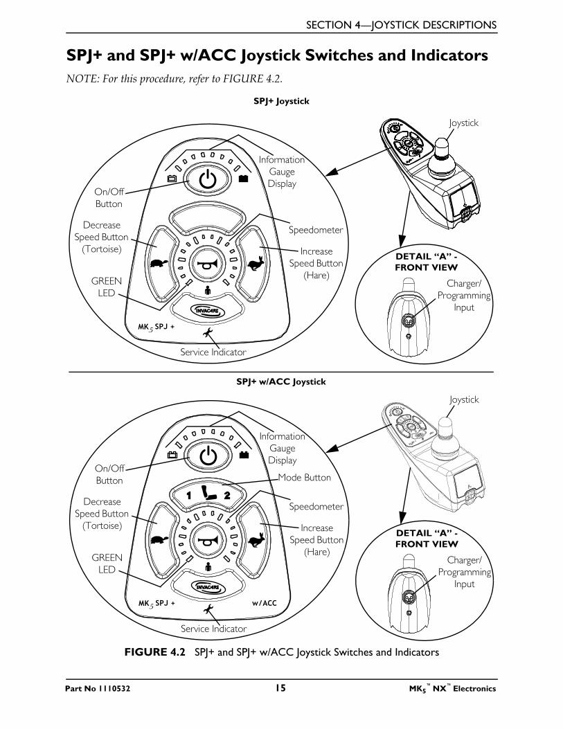
SPJ+ and SPJ+ w/ACC Joystick Switches and Indicators
NOTE: For this procedure, refer to FIGURE 4.2.
FIGURE 4.2 SPJ+ and SPJ+ w/ACC Joystick Switches and Indicators
On/Off
Button
DETAIL “A” -
FRONT VIEW
Charger/
Programming
Input
Speedometer
Joystick
GREEN
LED
Information
Gauge
Display
Service Indicator
Decrease
Speed Button
(Tortoise) Increase
Speed Button
(Hare)
Mode Button
SPJ+ w/ACC Joystick
On/Off
Button
DETAIL “A” -
FRONT VIEW
Charger/
Programming
Input
Speedometer
Joystick
GREEN
LED
Information
Gauge
Display
Service Indicator
Decrease
Speed Button
(Tortoise) Increase
Speed Button
(Hare)
SPJ+ Joystick
Part No 1110532 15 MK5™
NX™
Electronics

SECTION 4—JOYSTICK DESCRIPTIONS
On/Off Button
This button is located at the front of the joystick housing. It is used to turn the wheelchair on and off, to remove the joystick from sleep mode (if programmed) and to lock or unlock the joystick (if programmed).
Speedometer
The speedometer is used to show the maximum speed. The right-most LED indicates current maximum speed setting. The bottom left GREEN LED flashes to indicate that the joystick is in speed limit mode. Speed limit mode limits the drive speed to a pre-programmed value, typically when the seat has been elevated and the wheelchair is required to drive at 20% speed.
Speed Control Buttons
The speed control buttons (tortoise button ( ) and hare button ( )) are used to set and
adjust the maximum speed.
1. To adjust the speed, perform one (1) of the following:
• Adjust Speed in 20% Increments (5 Speed Mode) - Press the tortoise button ( )
or hare button ( ) to decrease/increase the speed in 20% increments. The larger
bars in the speedometer will light.
• Adjust Speed in Smaller Increments (VSP Mode) - Perform the following steps:
i. Press and hold both the tortoise button ( ) and hare button ( ) until the
joystick beeps.
ii. Perform one (1) of the following:
• Press the tortoise button ( ) or hare button ( ) to decrease/increase the
speed in 20% increments. The larger bars in the speedometer will light.
• Press and hold the tortoise button ( ) or hare button ( ) to decrease/
increase the speed in smaller increments. The smaller bars in the speedometer will light.
Mode Button
NOTE: The mode button is present on the SPJ+ w/ACC joystick only.
Press the mode button to switch from driving mode to elevate mode. Refer to the wheelchair owner’s manual for elevating seat operating instructions.
MK5™
NX™
Electronics 16 Part No 1110532

SECTION 4—JOYSTICK DESCRIPTIONS
Joystick
The joystick has proportional drive control, meaning that further the joystick is pushed from the upright (neutral) position, the faster the wheelchair or seat moves. Your top speed, however, is limited by the programmed settings.
To slow the wheelchair to a stop, simply release the joystick. The wheelchair has automatic speed and direction compensation to minimize corrections.
Charger/Programming Input
The charger/programming input is located at the front of the joystick housing. This provides easy access for charging the wheelchair batteries. This port also serves as the Remote Programmer Communication connection. Driving is prevented while the system is charging.
Service Indicator
The AMBER service indicator will light when an error or fault occurs. Refer to Diagnostic Codes on page 33 for a listing of the flash codes and what they indicate.
Information Gauge Display
Located on the front of the joystick housing, it provides the following information to the user on the status of the wheelchair -
1. Power is on.
2. True state-of-battery-charge, including notification of when the battery requires charging:
A. GREEN LEDs are lit, indicating well charged batteries.
B. AMBER LEDs are lit, indicating batteries are moderately charged. Recharge batteries before taking a long trip.
C. RED LEDs are lit, indicating batteries are running out of charge. Recharge batteries as soon as possible.
The Information Gauge display also serves as a system diagnostic device when a fault is detected by the control module. A specific number of flashes of the LEDs indicate the type of fault detected. Refer to the table for the diagnostic indications of the wheelchair status.
Part No 1110532 17 MK5™
NX™
Electronics

SECTION 4—JOYSTICK DESCRIPTIONS
DISPLAY DESCRIPTION DEFINITION COMMENTS
All LEDs are off. Power is off.
All LEDs are on. Power is on. Fewer than three (3)
LEDs on implies reduced
battery charge.
Left RED LED is flashing. Battery charge is low. The batteries should be
charged as soon as possi-
ble.
Right to Left “chase”. Joystick is being brought
out of LOCK mode.
To UNLOCK the joystick,
press the horn button
two (2) times within ten
(10) seconds.
Left to Right “chase” alter-
nating with steady display.
Joystick is in program-
ming, inhibit and/or charg-
ing mode.
The steady LEDs indicate
the current state of the
battery charge.
All LEDs are flashing slowly. Joystick has detected Out-
of-Neutral-at-Power-Up
mode.
Release the joystick back
to Neutral.
MK5™
NX™
Electronics 18 Part No 1110532
SECTION 5—REMOTE PROGRAMMER
SECTION 5—REMOTE
PROGRAMMER
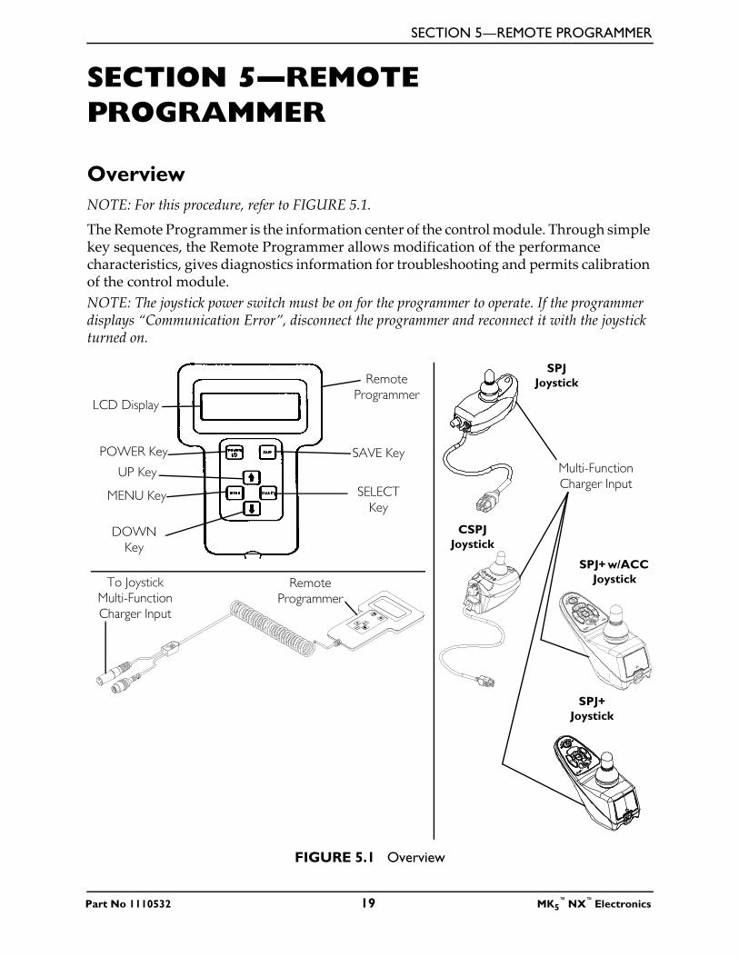
Overview
NOTE: For this procedure, refer to FIGURE 5.1.
The Remote Programmer is the information center of the control module. Through simple key sequences, the Remote Programmer allows modification of the performance characteristics, gives diagnostics information for troubleshooting and permits calibration of the control module.
NOTE: The joystick power switch must be on for the programmer to operate. If the programmer displays “Communication Error”, disconnect the programmer and reconnect it with the joystick turned on.
FIGURE 5.1 Overview
SAVE Key
SELECT
Key
POWER Key
MENU Key
DOWN
Key
UP Key
LCD Display
Remote
Programmer
Remote
Programmer
To Joystick
Multi-Function
Charger Input
Multi-Function
Charger Input
SPJ
Joystick
CSPJ
Joystick
SPJ+ w/ACC
Joystick
SPJ+
Joystick
Part No 1110532 19 MK5™
NX™
Electronics

SECTION 5—REMOTE PROGRAMMER
Remote Programmer Terminology
Function
A function is a performance characteristic which can be adjusted or modified to improve the operation of the wheelchair for a particular control need. Two (2) examples are:
The forward speed function may be adjusted to a higher or lower speed the same way as you would adjust a trimpot in other controls.
Stand-by Mode Function may be turned ON or OFF the same as a switch would be used. All functions are listed in a menu.
Value
Each function has a value. It is the degree or amount of the function which is used to influence the overall wheelchair performance. Most values are numerical or in percentages, for instance - high speed may be set to 75% of the wheelchair's maximum. For others, the value is either ON or OFF, for example - Stand-by Mode. Changing a value is called Adjustment.
Program (Preset Programs with Standard Value Settings)
The standard programs are fixed function values which are used as an initial set up point from which individualization of the wheelchair performance can begin. Standard values are NEVER altered or modified. Refer to Programs on page 29.
Temporary Memory
This is the location where function values may be altered to suit individual needs by using the remote programmer. Unless saved, changes to the values in the temporary memory will be erased when the wheelchair power is turned off. Refer to User Memory Values below.
User Memory Values
User memory is the location where the individualized function values are permanently stored. Each time the power switch is turned on, these values are copied to the temporary memory and are used to control the wheelchair performance. The user memory values can only be changed through the Remote Programmer by first modifying the temporary memory values and then by saving them in the user memory where they become the user program. The Remote Programmer is activated by pressing the POWER key when the wheelchair is in neutral. The wheelchair cannot be driven when the LCD display is illuminated. The display will automatically turn itself OFF after 45 seconds if no keys are pressed. It can also be turned OFF by pressing the POWER key.
MK5™
NX™
Electronics 20 Part No 1110532

SECTION 5—REMOTE PROGRAMMER
Description Of Remote Programmer Keys
KEY DESCRIPTION
POWER KEY The POWER key turns on and off the LCD display. Press the POWER key
once and the display will come ON. Press the POWER key again and the
display will turn OFF.
MENU KEY The MENU key returns the LCD display to the previous screen. If a func-
tion is being adjusted, pressing the MENU key returns the display to the
Performance Menu. Pressing the key again will cause the display to change
to the Main Menu.
UP AND DOWN KEYS These keys are used to move the selection arrow on the LCD up and
down or adjust a value up or down. An adjusted value is not saved unless
the SAVE key is pressed.
SELECT KEY The SELECT key chooses the item to which the selection arrow on the
LCD is pointing and displays the appropriate next screen.
SAVE KEY The SAVE key causes the Save screen to appear or causes the values that
have been modified in temporary memory to be permanently stored in the
driving program specified by the selection arrow.
Part No 1110532 21 MK5™
NX™
Electronics
SECTION 6—PERFORMANCE ADJUSTMENTS
SECTION 6—PERFORMANCE
ADJUSTMENTS
Main Menu
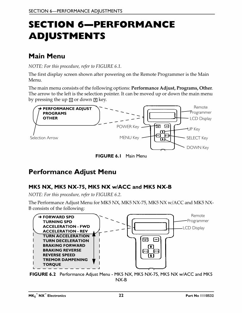
NOTE: For this procedure, refer to FIGURE 6.1.
The first display screen shown after powering on the Remote Programmer is the Main Menu.
The main menu consists of the following options: Performance Adjust, Programs, Other. The arrow to the left is the selection pointer. It can be moved up or down the main menu by pressing the up or down key.
FIGURE 6.1 Main Menu
Performance Adjust Menu
MK5 NX, MK5 NX-75, MK5 NX w/ACC and MK5 NX-B
NOTE: For this procedure, refer to FIGURE 6.2.
The Performance Adjust Menu for MK5 NX, MK5 NX-75, MK5 NX w/ACC and MK5 NX-B consists of the following:
FIGURE 6.2 Performance Adjust Menu - MK5 NX, MK5 NX-75, MK5 NX w/ACC and MK5
NX-B
LCD Display
Remote
Programmer➜ PERFORMANCE ADJUST
PROGRAMS
OTHER
Selection Arrow
UP Key
SELECT Key
DOWN Key
MENU Key
POWER Key
LCD Display
Remote
Programmer➜ FORWARD SPD
TURNING SPD
ACCELERATION - FWD
ACCELERATION - REV
TURN ACCELERATION
TURN DECELERATION
BRAKING FORWARD
BRAKING REVERSE
REVERSE SPEED
TREMOR DAMPENING
TORQUE
MK5™
NX™
Electronics 22 Part No 1110532
SECTION 6—PERFORMANCE ADJUSTMENTS
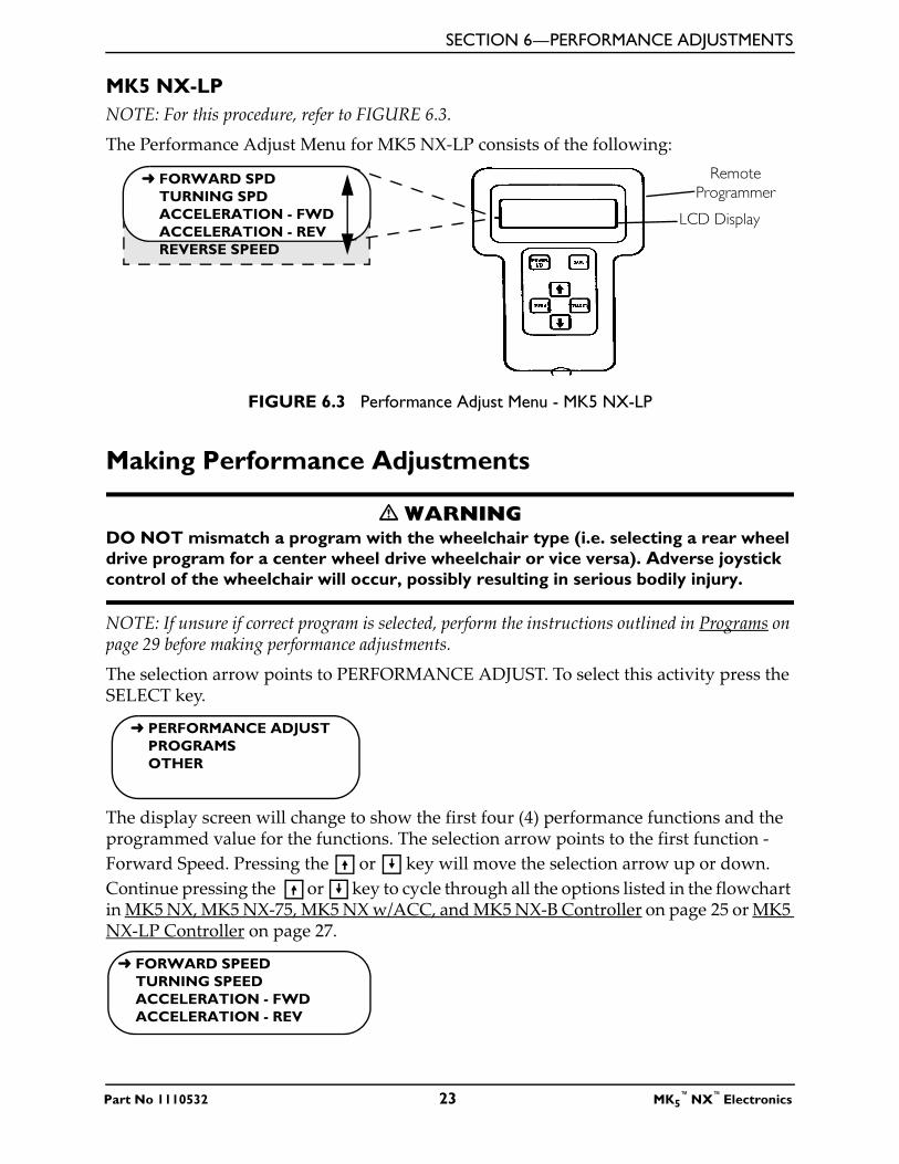
MK5 NX-LP
NOTE: For this procedure, refer to FIGURE 6.3.
The Performance Adjust Menu for MK5 NX-LP consists of the following:
FIGURE 6.3 Performance Adjust Menu - MK5 NX-LP
Making Performance Adjustments
� WARNING
DO NOT mismatch a program with the wheelchair type (i.e. selecting a rear wheel
drive program for a center wheel drive wheelchair or vice versa). Adverse joystick
control of the wheelchair will occur, possibly resulting in serious bodily injury.
NOTE: If unsure if correct program is selected, perform the instructions outlined in Programs on page 29 before making performance adjustments.
The selection arrow points to PERFORMANCE ADJUST. To select this activity press the SELECT key.
The display screen will change to show the first four (4) performance functions and the programmed value for the functions. The selection arrow points to the first function -
Forward Speed. Pressing the or key will move the selection arrow up or down.
Continue pressing the or key to cycle through all the options listed in the flowchart in MK5 NX, MK5 NX-75, MK5 NX w/ACC, and MK5 NX-B Controller on page 25 or MK5 NX-LP Controller on page 27.
LCD Display
Remote
Programmer➜ FORWARD SPD
TURNING SPD
ACCELERATION - FWD
ACCELERATION - REV
REVERSE SPEED
➜ PERFORMANCE ADJUST
PROGRAMS
OTHER
➜ FORWARD SPEED
TURNING SPEED
ACCELERATION - FWD
ACCELERATION - REV
Part No 1110532 23 MK5™
NX™
Electronics

SECTION 6—PERFORMANCE ADJUSTMENTS
To change the programmed value for an option (i.e. Acceleration - FWD), press the key so the selection arrow points to Acceleration - FWD.
Press the SELECT key. The display screen changes to the adjustment screen. The top line shows the function. The second line shows the value. At the bottom is a bar graph which shows the relative position of the current value to the total adjustment range. Pressing the
or key will adjust the value.
Pressing the key causes the value to increase and the bar graph to move to the right.
Pressing the key causes the value to decrease and the bar graph to move to the left.
To save this change, press the SAVE key.
When saving to the drive program is complete, the screen will change to display:
*NOTE: The driving program selected is either RWD-2 Pole, RWD - 4 Pole, or CWD 2 - Pole. Refer to the flow chart in MK5 NX, MK5 NX-75, MK5 NX w/ACC, and MK5 NX-B Controller on page 25 or MK5 NX-LP Controller on page 27.
Pressing the MENU key allows the adjustment sequence to be repeated for other driving programs.
FORWARD SPEED
TURNING SPEED
➜ ACCELERATION - FWD
ACCELERATION - REV
ACCELERATION - FWD
35%
[ ]
ACCELERATION - FWD
70%
[ ]
CHANGES SAVED TO
*RWD - 2 POLE
CONTINUE? PRESS MENU
QUIT? PRESS POWER
MK5™
NX™
Electronics 24 Part No 1110532

SECTION 6—PERFORMANCE ADJUSTMENTS
MK5 NX, MK5 NX-75, MK5 NX w/ACC, and MK5 NX-B Controller
Flowchart
NOTE: For this procedure, refer to FIGURE 6.4.
Below is a flowchart on how to use a hand held programmer to select and modify functions.
FIGURE 6.4 MK5 NX, MK5 NX-75, MK5 NX w/ACC, and MK5 NX-B Controller
Part No 1110532 25 MK5™
NX™
Electronics
SECTION 6—PERFORMANCE ADJUSTMENTS
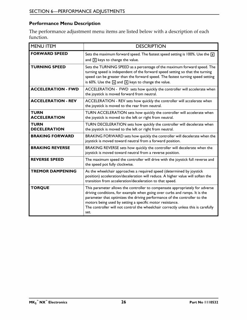
Performance Menu Description
The performance adjustment menu items are listed below with a description of each function.
MENU ITEM DESCRIPTION
FORWARD SPEED Sets the maximum forward speed. The fastest speed setting is 100%. Use the
and keys to change the value.
TURNING SPEED Sets the TURNING SPEED as a percentage of the maximum forward speed. The
turning speed is independent of the forward speed setting so that the turning
speed can be greater than the forward speed. The fastest turning speed setting
is 60%. Use the and keys to change the value.
ACCELERATION - FWD ACCELERATION - FWD sets how quickly the controller will accelerate when
the joystick is moved forward from neutral.
ACCELERATION - REV ACCELERATION - REV sets how quickly the controller will accelerate when
the joystick is moved to the rear from neutral.
TURN
ACCELERATION
TURN ACCELERATION sets how quickly the controller will accelerate when
the joystick is moved to the left or right from neutral.
TURN
DECELERATION
TURN DECELERATION sets how quickly the controller will decelerate when
the joystick is moved to the left or right from neutral.
BRAKING FORWARD BRAKING FORWARD sets how quickly the controller will decelerate when the
joystick is moved toward neutral from a forward position.
BRAKING REVERSE BRAKING REVERSE sets how quickly the controller will decelerate when the
joystick is moved toward neutral from a reverse position.
REVERSE SPEED The maximum speed the controller will drive with the joystick full reverse and
the speed pot fully clockwise.
TREMOR DAMPENING As the wheelchair approaches a required speed (determined by joystick
position) acceleration/deceleration will reduce. A higher value will soften the
transition from acceleration/deceleration to that speed.
TORQUE This parameter allows the controller to compensate appropriately for adverse
driving conditions, for example when going over curbs and ramps. It is the
parameter that optimizes the driving performance of the controller to the
motors being used by setting a specific motor resistance.
The controller will not control the wheelchair correctly unless this is carefully
set.
MK5™
NX™
Electronics 26 Part No 1110532

SECTION 6—PERFORMANCE ADJUSTMENTS
MK5 NX-LP Controller
Flowchart
NOTE: For this procedure, refer to FIGURE 6.5.
Below is a flowchart on how to use a hand held programmer to select and modify functions.
FIGURE 6.5 MK5 NX-LP Controller
Part No 1110532 27 MK5™
NX™
Electronics
SECTION 6—PERFORMANCE ADJUSTMENTS
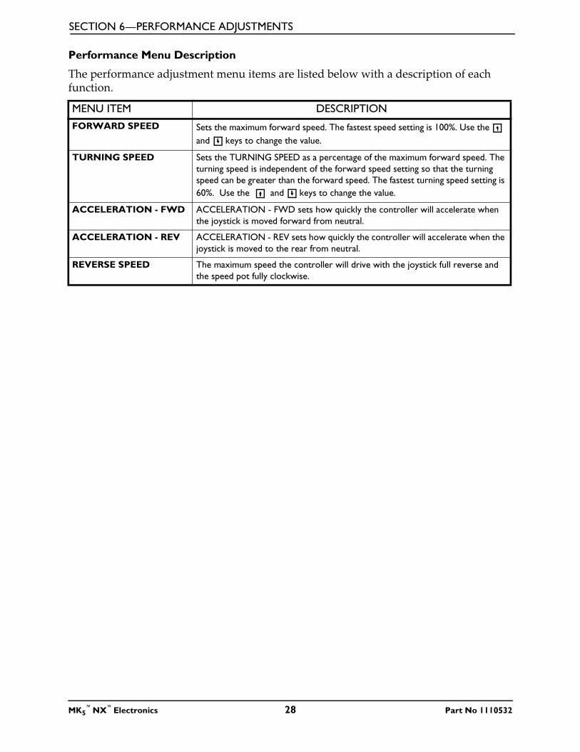
Performance Menu Description
The performance adjustment menu items are listed below with a description of each function.
MENU ITEM DESCRIPTION
FORWARD SPEED Sets the maximum forward speed. The fastest speed setting is 100%. Use the
and keys to change the value.
TURNING SPEED Sets the TURNING SPEED as a percentage of the maximum forward speed. The
turning speed is independent of the forward speed setting so that the turning
speed can be greater than the forward speed. The fastest turning speed setting is
60%. Use the and keys to change the value.
ACCELERATION - FWD ACCELERATION - FWD sets how quickly the controller will accelerate when
the joystick is moved forward from neutral.
ACCELERATION - REV ACCELERATION - REV sets how quickly the controller will accelerate when the
joystick is moved to the rear from neutral.
REVERSE SPEED The maximum speed the controller will drive with the joystick full reverse and
the speed pot fully clockwise.
MK5™
NX™
Electronics 28 Part No 1110532

SECTION 7—PROGRAMS
SECTION 7—PROGRAMS
Program Settings
� WARNING
DO NOT mismatch a program with the wheelchair type (i.e. selecting a rear wheel
drive program for a center wheel drive wheelchair or vice versa). Confirm that the
settings and program match the wheelchair before selecting or saving. Otherwise,
unintended and unsafe joystick control of the wheelchair will occur, possibly result-
ing in serious bodily injury.
The program settings are available as a reference point for initial set-up of the wheelchair, for final user setting or whenever major changes have been made in the performance and a known starting point needs to be reestablished. Confirm that the settings and program match the wheelchair before selecting or saving.
Three (3) programs are available.
1. Select PROGRAMS from the main menu to display the standard value menu.
2. Press or and then the SELECT key to select the standard program to be placed in the temporary memory.
3. Press the SAVE key to store the program into a selected drive.
4. Make changes to specific functions as needed.
The general capabilities of the standard programs are listed below:
NOTE: If the default settings in the following tables are not desired, they will need to be changed manually. Performance Adjustments on page 22.
PROGRAMMER READS DRIVE TYPE MOTOR TYPE
RWD Rear Wheel Drive 2-Pole
RWD Rear Wheel Drive 4-Pole
ATM Rear Wheel Drive 2-Pole
CWD Center Wheel Drive 2-Pole
MWD Center Wheel Drive 2-Pole
Part No 1110532 29 MK5™
NX™
Electronics

SECTION 7—PROGRAMS
DEFAULT SETTINGS FOR MK5 NX
FUNCTION PROGRAM 1 PROGRAM 2 PROGRAM 3
RWD 2-POLE RWD 4-POLE CWD 2-POLE
FORWARD SPEED 95 90 100
TURNING SPEED 25 20 30
ACCELERATION - FWD 30 25 25
ACCELERATION - REV 30 20 25
TURN ACCELERATION 30 20 25
TURN DECELERATION 35 25 30
BRAKING FORWARD 50 50 50
BRAKING REVERSE 55 45 55
REVERSE SPEED 40 30 40
TREMOR DAMPENING 40 40 40
TORQUE 144 48 144
DEFAULT SETTINGS FOR MK5 NX-B
FUNCTION PROGRAM 1 PROGRAM 2 PROGRAM 3
ATM 2-POLE RWD 2-POLE CWD 2-POLE
FORWARD SPEED 95 95 100
TURNING SPEED 50 25 30
ACCELERATION - FWD 30 30 25
ACCELERATION - REV 30 30 25
TURN ACCELERATION 80 30 25
TURN DECELERATION 75 35 30
BRAKING FORWARD 85 50 50
BRAKING REVERSE 55 55 55
REVERSE SPEED 40 40 40
TREMOR DAMPENING 40 40 40
TORQUE 144 144 144
MK5™
NX™
Electronics 30 Part No 1110532

SECTION 7—PROGRAMS
DEFAULT SETTINGS FOR MK5 NX W/ACC
FUNCTION PROGRAM 1 PROGRAM 2 PROGRAM 3
MWD - M61 (1) MWD - M61 (2) MWD - M61 (3)
FORWARD SPEED 95 95 95
TURNING SPEED 25 25 25
ACCELERATION - FWD 25 25 25
ACCELERATION - REV 25 25 25
TURN ACCELERATION 30 30 30
TURN DECELERATION 30 30 30
BRAKING FORWARD 50 50 50
BRAKING REVERSE 55 55 55
REVERSE SPEED 40 40 40
TREMOR DAMPENING 35 35 35
TORQUE 144 144 144
DEFAULT SETTINGS FOR MK5 NX-75
FUNCTION PROGRAM 1 PROGRAM 2 PROGRAM 3
CWD M91 CWD M91 HD CWD M91
FORWARD SPEED 95 95 95
TURNING SPEED 20 20 20
ACCELERATION - FWD 20 20 20
ACCELERATION - REV 20 20 20
TURN ACCELERATION 25 20 25
TURN DECELERATION 35 20 35
BRAKING FORWARD 50 50 50
BRAKING REVERSE 55 55 55
REVERSE SPEED 50 40 50
TREMOR DAMPENING 35 40 35
TORQUE 36 36 36
DEFAULT SETTINGS FOR MK5 NX-LP
FUNCTION PROGRAM 1 PROGRAM 2 PROGRAM 3
RWD 2-POLE RWD 4-POLE CWD 2-POLE
FORWARD SPEED 95 90 100
TURNING SPEED 25 20 30
ACCELERATION - FWD 30 25 25
ACCELERATION - REV 30 20 25
REVERSE SPEED 40 30 40
Part No 1110532 31 MK5™
NX™
Electronics

SECTION 8—OTHER FUNCTIONS
MK5™
NX™
Electronics 32 Part No 1110532
SECTION 8—OTHER FUNCTIONS
Description of Other Functions
Select OTHER from the main menu to display Motor Balance, Joystick Throw, Fault Log,
and Usage Statistics. Use the and keys to select the function desired. The SELECT key will display the current value and permit modifications. Always press SAVE after changes are made.
NOTE: At any point, press the MENU key to return to the previous screen.
MENU ITEM DESCRIPTION
MOTOR BALANCE Motor balance corrects for veer when going straight on level ground. To correct
for a veer to the right, move the bar graph indicator to the right using the key.
To correct for veer to the left, move the bar graph indicator to the left using the
key.
JOYSTICK THROW Joystick throw calibration is used to calibrate the neutral position and the full speed
travel of the proportional joystick. The control module stores the maximum dis-
placement of the joystick and later, during driving, uses the values to generate a full
speed command whenever that displacement is reached. Exceeding this displace-
ment does not product further increase in speed. The result of this method of cali-
bration is a customized driving template.
FAULT LOG The Fault Log shows the fault codes that have been detected by the diagnostic sys-
tem since the control was built in the factory. The fault codes correspond to the
Diagnostics Codes given in the next section. The Fault Log can be used by the ser-
vice technician to uncover the cause of intermittent faults that are not evident when
the wheelchair is being serviced.
NOTE: It is normal to have some codes in the Fault Log, even in a new wheelchair, because
they are generated during factory testing and calibration.
USAGE STATISTICS The usage statistics screen displays how long the wheelchair has been on in hours:
minutes, the total number of times the wheelchair has been powered up and how
many times the wheelchair has been driven.

SECTION 9—DIAGNOSTIC CODES
SECTION 9—DIAGNOSTIC CODES
What Are Diagnostics Codes?
The joystick information gauge and the Remote Programmer give indications of the type of fault or error detected by the control module. When a fault is detected, the wheelchair will stop and not drive. All of the lights on the information gauge will begin to flash (SPJ and CSPJ joysticks) or the service indicator light will flash (SPJ+ and SPJ+ w/ACC joystick). The number of flashes indicates the nature of an abnormal condition. An error code and a quick description of the fault will begin to scroll across the Remote Programmer display. If multiple faults are found, only the first fault encountered by the control module program will be displayed. Refer to the Power Wheelchair Service Manual for detailed troubleshooting and repair instructions. A table of the diagnostics codes and their causes follows.
*NOTE: The fault log displays a four (4) digit number. The first two (2) digits are the diagnostic code and the remaining two (2) digits are the sub code.
NU
MB
ER
OF F
LA
SH
ES
DIA
GN
OST
ICS C
OD
E
ER
RO
R C
OD
E
DESC
RIP
TIO
N
SU
B C
OD
E*
DET
AIL
S O
F
ER
RO
R C
OD
E
PO
SSIB
LE
SO
LU
TIO
N1 E 01 User Fault 00 Stall Timeout or user error. Release joystick to neutral and try again.
2 E02 Battery Fault 00 Recharge batteries or replace. Check the batteries and cable. Try charg-
ing the batteries. Batteries may require
replacing.
3 E03 Left Motor Fault 00 Left Motor Short Circuit Check the left motor, connections and
motor cable.01 Left Motor Open Circuit
02 Left Motor Connection Fault
B-
03 Motor Terminal Connected
to B+
04 Left Motor Voltage Fault
05 Left Motor Bridge Fault
06 Too Many Hardware Cur-
rent Limit Events
07 Current Offset Out of Range
08 Hardware Current Limit Fault
Part No 1110532 33 MK5™
NX™
Electronics

SECTION 9—DIAGNOSTIC CODES
4 E04 Right Motor Fault 00 Right Motor Short Circuit Check the right motor, connections and
motor cable.01 Right Motor Open Circuit
02 Right Motor Connection Fault
B-
03 Motor Terminal Connected
to B+
04 Right Motor Voltage Fault
05 Right Motor Bridge Fault
06 Too Many Hardware Cur-
rent Limit Events
07 Current Offset Out of Range
08 Hardware Current Limit Fault
5 E05 Left Park Brake
Fault
00 Left Park Brake Drive-Time
Test Failed
Check the left park brake connections and
cable.
01 Left Park Brake Output
Enabled When Wheelchair
Idle
02 Left Park Brake Output Did
not Enable When Entering
Drive Mode
03 Left Park Brake fault during
power-up testing
04 Left park brake feedback low
during drive (park brake
short?)
6 E06 Right Park Brake
Fault
00 Right Park Brake Drive-Time
Test Failed
Check the right park brake connections
and cable.
01 Right Park Brake Output
Enabled When Wheelchair
Idle
02 Right Park Brake Output Did
not Enable When Entering
Drive Mode
03 Right Park Brake fault during
power-up testing
04 Right park brake feedback
low during drive (park brake
short?)
NU
MB
ER
OF F
LA
SH
ES
DIA
GN
OST
ICS C
OD
E
ER
RO
R C
OD
E
DESC
RIP
TIO
N
SU
B C
OD
E*
DET
AIL
S O
F
ER
RO
R C
OD
E
PO
SSIB
LE
SO
LU
TIO
N
MK5™
NX™
Electronics 34 Part No 1110532

SECTION 9—DIAGNOSTIC CODES
7 E07 Remote Fault 00 Local SR Fault (CPU,
EEPROM, etc.)
Check the communications bus, connec-
tions and wiring. Replace the remote.
01 Joystick fault at the remote
02 Speed pot fault at the remote
8 E08 Controller Fault 00 Controller fault Check connections and wiring. Replace
power module.01 RAM fault
02 ROM fault
03 CPU fault
04 EEPROM fault
05 Watchdog fault
06 Stack fault
07 Software fault
08 Power-up testing fault
09 Relay fault or precharge fault
10 Bridge fault or disable all fault
11 Electronics fault: Thermistor
12 Calibration setting fault
9 E09 Communications
Fault
00 Remote connection lost Check connections and wiring. Replace
Bus cable.01 Low communication mode
10 E10 General Fault 00 General fault Check all connections and wiring. Contact
Invacare Technical Service.
11 E11 Incompatible/
incorrect Remote
00 Incompatible/incorrect
Remote
Wrong type of remote connected. Ensure
the branding of the joystick matches that
of controller unit.
NU
MB
ER
OF F
LA
SH
ES
DIA
GN
OST
ICS C
OD
E
ER
RO
R C
OD
E
DESC
RIP
TIO
N
SU
B C
OD
E*
DET
AIL
S O
F
ER
RO
R C
OD
E
PO
SSIB
LE
SO
LU
TIO
N
Part No 1110532 35 MK5™
NX™
Electronics

SECTION 10—CONNECTOR DESCRIPTIONS
SECTION 10—CONNECTOR
DESCRIPTIONS
Controller Connector Descriptions
MK5 NX, NX-75, NX-B and NX-LP
NOTE: For this procedure, refer to FIGURE 10.1.
FIGURE 10.1 MK5 NX, NX-75, NX-B and NX-LP
MK5 NX w/ACC
NOTE: For this procedure, refer to FIGURE 10.2.
FIGURE 10.2 MK5 NX w/ACC
Front of
Controller
Front of
Controller
MK5™
NX™
Electronics 36 Part No 1110532

SECTION 10—CONNECTOR DESCRIPTIONS
Battery Connector Pinout
NOTE: For this procedure, refer to FIGURE 10.3.
FIGURE 10.3 Battery Connector Pinout
Motor Connector Pinout
NOTE: For this procedure, refer to FIGURE 10.4.
FIGURE 10.4 Motor Connector Pinout
Joystick Connector Pinout
NOTE: For this procedure, refer to FIGURE 10.5.
FIGURE 10.5 Joystick Connector Pinout
Drive Control Input (DCI)
NOTE: Wheelchairs equipped with DCI have seating options (i.e. elevate and tilt).
The DCI allows the wheelchair mode to depend on the resistance of the DCI “Loop”:
• Inhibit - prevents the wheelchair from driving, typically when the wheelchair is being charged, or when the seat is tilted.
• Slow - limits the drive speed to a predetermined value, typically when the seat is raised.
To determine the mode, an appropriate resistance must be placed across the DCI input pin (I) and the DCI Battery Negative (-) pin. Depending on the resistance value, the controller will inhibit, slow, and/or swivel driving. Resistors used must be 5% tolerance resistors.
PIN FUNCTION
1 Battery Positive
2 Battery Negative
1 2
PIN FUNCTION
1 Motor Positive
2 Motor Negative
3 Park Brake Negative
4 Park Brake Positive
1 2
4
3
PIN FUNCTION
1 Battery Positive
2 Communication Bus High
3 Communication Bus Low
4 Battery Negative
1 2
43
MODE RESISTANCEInhibit 0
Slow 120
Normal Open
Part No 1110532 37 MK5™
NX™
Electronics
SECTION 10—CONNECTOR DESCRIPTIONS
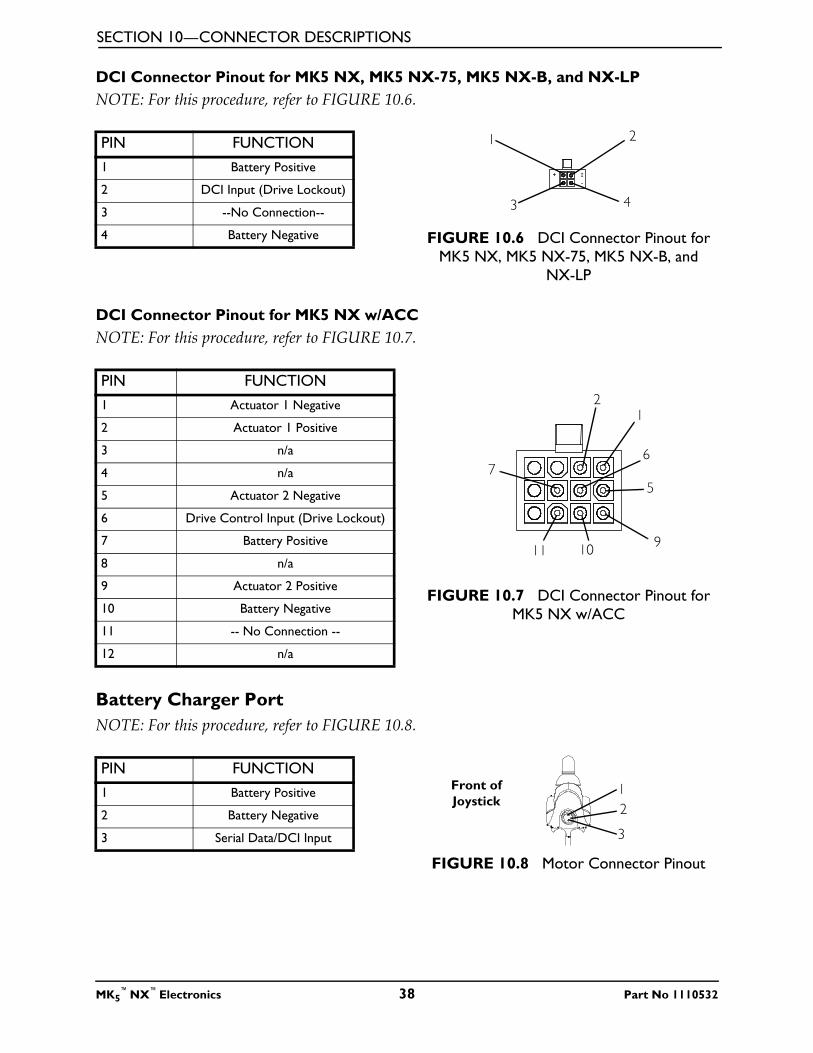
DCI Connector Pinout for MK5 NX, MK5 NX-75, MK5 NX-B, and NX-LP
NOTE: For this procedure, refer to FIGURE 10.6.
FIGURE 10.6 DCI Connector Pinout for
MK5 NX, MK5 NX-75, MK5 NX-B, and
NX-LP
DCI Connector Pinout for MK5 NX w/ACC
NOTE: For this procedure, refer to FIGURE 10.7.
FIGURE 10.7 DCI Connector Pinout for
MK5 NX w/ACC
Battery Charger Port
NOTE: For this procedure, refer to FIGURE 10.8.
FIGURE 10.8 Motor Connector Pinout
PIN FUNCTION
1 Battery Positive
2 DCI Input (Drive Lockout)
3 --No Connection--
4 Battery Negative
1 2
43
PIN FUNCTION
1 Actuator 1 Negative
2 Actuator 1 Positive
3 n/a
4 n/a
5 Actuator 2 Negative
6 Drive Control Input (Drive Lockout)
7 Battery Positive
8 n/a
9 Actuator 2 Positive
10 Battery Negative
11 -- No Connection --
12 n/a
12
5
67
91011
PIN FUNCTION
1 Battery Positive
2 Battery Negative
3 Serial Data/DCI Input
1
2
3
Front of
Joystick
MK5™
NX™
Electronics 38 Part No 1110532

LIMITED WARRANTY
Part No 1110532 39 MK5™
NX™
Electronics
LIMITED WARRANTYPLEASE NOTE: THE WARRANTY BELOW HAS BEEN DRAFTED TO COMPLY WITH
FEDERAL LAW APPLICABLE TO PRODUCTS MANUFACTURED AFTER JULY 4, 1975.
This warranty is extended only to the original purchaser/user of our products.
This warranty gives you specific legal rights and you may also have other legal rights which vary
from state to state.
Invacare warrants the MK5 NX, MK5 NX-75, MK5 NX-LP, MK5 NX-B and MK5 NX w/ACC
Controller to be free from defects in materials and workmanship for a period of one (1) year
from date of purchase. If within such warranty period any such product shall be proven to be
defective, such product shall be repaired or replaced, at Invacare's option. This warranty does
not include any labor or shipping charges incurred in replacement part installation or repair of
any such product. Invacare's sole obligation and your exclusive remedy under this warranty
shall be limited to such repair and/or replacement.
For warranty service, please contact the dealer from whom you purchased your Invacare
product. In the event you do not receive satisfactory warranty service, please write directly to
Invacare at the address at the bottom of the back cover. Provide dealer’s name, address, date
of purchase, indicate nature of the defect and, if the product is serialized, indicate the serial
number. Do not return products to our factory without our prior consent.
LIMITATIONS AND EXCLUSIONS: THE FOREGOING WARRANTY SHALL NOT APPLY
TO SERIAL NUMBERED PRODUCTS IF THE SERIAL NUMBER HAS BEEN REMOVED OR
DEFACED, PRODUCTS SUBJECTED TO NEGLIGENCE, ACCIDENT, IMPROPER
OPERATION, MAINTENANCE OR STORAGE, COMMERCIAL OR INSTITUTIONAL USE,
PRODUCTS MODIFIED WITHOUT INVACARE'S EXPRESS WRITTEN CONSENT
INCLUDING, BUT NOT LIMITED TO, MODIFICATION THROUGH THE USE OF
UNAUTHORIZED PARTS OR ATTACHMENTS; PRODUCTS DAMAGED BY REASON OF
REPAIRS MADE TO ANY COMPONENT WITHOUT THE SPECIFIC CONSENT OF
INVACARE, OR TO A PRODUCT DAMAGED BY CIRCUMSTANCES BEYOND INVACARE'S
CONTROL, AND SUCH EVALUATION WILL BE SOLELY DETERMINED BY INVACARE.
THE WARRANTY SHALL NOT APPLY TO PROBLEMS ARISING FROM NORMAL WEAR
OR FAILURE TO ADHERE TO THESE INSTRUCTIONS.
THE FOREGOING EXPRESS WARRANTY IS EXCLUSIVE AND IN LIEU OF ANY OTHER
WARRANTIES WHATSOEVER, WHETHER EXPRESS OR IMPLIED, INCLUDING THE
IMPLIED WARRANTIES OF MERCHANTABILITY AND FITNESS FOR A PARTICULAR
PURPOSE, AND THE SOLE REMEDY FOR VIOLATIONS OF ANY WARRANTY
WHATSOEVER, SHALL BE LIMITED TO REPAIR OR REPLACEMENT OF THE DEFECTIVE
PRODUCT PURSUANT TO THE TERMS CONTAINED HEREIN. THE APPLICATION OF
ANY IMPLIED WARRANTY WHATSOEVER SHALL NOT EXTEND BEYOND THE
DURATION OF THE EXPRESS WARRANTY PROVIDED HEREIN. INVACARE SHALL NOT
BE LIABLE FOR ANY CONSEQUENTIAL OR INCIDENTAL DAMAGES WHATSOEVER.
THIS WARRANTY SHALL BE EXTENDED TO COMPLY WITH STATE/PROVINCIAL
LAWS AND REQUIREMENTS.
Invacare Corporation www.invacare.com
USA
One Invacare WayElyria, Ohio USA44036-2125800-333-6900
Canada
570 Matheson Blvd E Unit 8Mississauga OntarioL4Z 4G4 Canada800-668-5324
Invacare is a registered trademark of Invacare Corporation.Yes, you can., MK5, NX, SPJ and CSPJ are trademarks of Invacare Corporation.© 2005 Invacare Corporation
Part No 1110532
Rev F - 08/05