Embed Size (px)
Citation preview
Service Manual
DEALER: Keep this manual. The procedures in this manual MUST be performed by a qualified technician.
For more information regarding Invacare products, parts, and services, please visit
www.invacare.com
MK5™EX™ and MK5™TT-EX™
Electronics
MK5™EX™ and MK5
™TT-EX™ Electronics 2 Part No 1114808
� WARNINGA QUALIFIED TECHNICIAN MUST PERFORM THE INITIAL SET UP OF THIS WHEELCHAIR. ALSO, A QUALIFIED TECHNICIAN MUST PERFORM ALL PROCEDURES IN THE SERVICE MANUAL.
WHEELCHAIR USERS: DO NOT SERVICE OR OPERATE THIS EQUIPMENT WITHOUT FIRST READING AND UNDERSTANDING (1) THE OWNER’S OPERATOR AND MAINTENANCE MANUAL AND (2) THE SEATING SYSTEM’S MANUAL (IF APPLICABLE). IF YOU ARE UNABLE TO UNDERSTAND THE WARNINGS, CAUTIONS, AND INSTRUCTIONS, CONTACT INVACARE TECHNICAL SUPPORT BEFORE ATTEMPTING TO SERVICE OR OPERATE THIS EQUIPMENT - OTHERWISE INJURY OR DAMAGE MAY RESULT.
DEALERS AND QUALIFIED TECHNICIANS: DO NOT SERVICE OR OPERATE THIS EQUIPMENT WITHOUT FIRST READING AND UNDERSTANDING (1) THE OWNER’S OPERATOR AND MAINTENANCE MANUAL, (2) THE SERVICE MANUAL (IF APPLICABLE) AND (3) THE SEATING SYSTEM’S MANUAL (IF APPLICABLE). IF YOU ARE UNABLE TO UNDERSTAND THE WARNINGS, CAUTIONS AND INSTRUCTIONS, CONTACT INVACARE TECHNICAL SUPPORT BEFORE ATTEMPTING TO SERVICE OR OPERATE THIS EQUIPMENT - OTHERWISE, INJURY OR DAMAGE MAY RESULT.
NOTE: This manual is also available in French Canadian (Part Number 1123834).
NOTE: Updated versions of this manual are available on www.invacare.com.
TABLE OF CONTENTS
TABLE OF CONTENTS
SPECIAL NOTES ................................................................................ 7SECTION 1—EMI INFORMATION ....................................................... 8
SECTION 2—TROUBLESHOOTING .................................................... 10
All Power Wheelchairs ...........................................................................................................................10
Wheelchairs With Powered Seating Systems....................................................................................11
Formula™TRE only .............................................................................................................................12
SECTION 3—JOYSTICK DESCRIPTIONS ............................................. 14
Joystick Overview.....................................................................................................................................14
DPJ Joystick Switches and Indicators ...................................................................................................14
Power/Drive Select Toggle Switch ..................................................................................................14Selecting the Drive Mode .............................................................................................................14Turning the Wheelchair Off ........................................................................................................14
Speed Control Knob ...........................................................................................................................15Mode (On/Off) Switch ........................................................................................................................15Battery Gauge Display (BGD)...........................................................................................................15
MPJ Joystick Switches and Indicators ...................................................................................................15
Power/Drive Select Toggle Switch ..................................................................................................16Selecting the Drive Mode .............................................................................................................16Turning the Wheelchair Off ........................................................................................................16
Speed Control Knob ...........................................................................................................................16LCD Display ..........................................................................................................................................16Remote On/Off Input..........................................................................................................................17
SECTION 4—REMOTE PROGRAMMER .............................................. 18
Overview....................................................................................................................................................18
Remote Programmer Terminology ......................................................................................................18
Function..................................................................................................................................................18Value .......................................................................................................................................................19Standard Program (Preset Programs) .............................................................................................19User Memory Values...........................................................................................................................19
Description Of Remote Programmer Keys .......................................................................................19
SECTION 5—PERFORMANCE ADJUSTMENTS .................................... 20
Speed and Response Screen ..................................................................................................................20
Advanced Menu.........................................................................................................................................20
Performance Menu...................................................................................................................................20
Making Performance Adjustments........................................................................................................21
Performance Menu Description............................................................................................................24
SECTION 6—STANDARD VALUE SETTINGS ...................................... 32
Standard Value Settings ...........................................................................................................................32
Part No 3 Manual Title
TABLE OF CONTENTS
TABLE OF CONTENTS
SECTION 7—CALIBRATION OF THE CONTROL MODULE ................... 33When to Calibrate the Control Module.............................................................................................33
What Functions Can Be Calibrated .....................................................................................................33
Calibrating the Control Module............................................................................................................33
SECTION 8—CURRENT STATUS DISPLAY ......................................... 37
SECTION 9—DIAGNOSTIC CODES .................................................... 38
What Are Diagnostics Codes? ..............................................................................................................38
MK5 EX Controller Diagnostic Codes ...............................................................................................38
MK5 TT-EX Controller Diagnostic Codes ........................................................................................39
SECTION 10—OPTIONS ................................................................... 42
Display Unit................................................................................................................................................42
Drive Select and On/Off Switch .......................................................................................................42Selecting the Drive Mode .............................................................................................................42
LCD Display ..........................................................................................................................................43Remote On/Off ....................................................................................................................................43Special Purpose Indicators .................................................................................................................43
MK5 PSR/PSF Joysticks ............................................................................................................................44
Joystick Overview ................................................................................................................................44Power/Drive Select Toggle Switch ..................................................................................................45
Selecting the Drive Mode .............................................................................................................46Turning the Wheelchair Off ........................................................................................................46
Speed Control Knob ...........................................................................................................................46Battery Gauge Display (BGD)...........................................................................................................46Mode and Level Indicators.................................................................................................................46
1558M4 Compact Joystick......................................................................................................................47
1500M4 Rim Head Control ...................................................................................................................48
1812M4 Dual Proportional Joystick .....................................................................................................48
1554M5 or 1554M4 Sip & Puff Switch Input ......................................................................................49
Driver Control Input Connector.....................................................................................................49Proportional Attendant Connector.................................................................................................50Sip and Puff (Pneumatic Switch) Input.............................................................................................50Mounting Precautions and Maintenance .........................................................................................50Selecting the Driver Input Type .......................................................................................................50Calibrating the Sip & Puff Pressures ................................................................................................51
PACM5 Proportional Attendant Control ...........................................................................................52
Override and Speed Control Knob.................................................................................................52
1552M Attendant Control .....................................................................................................................53
On/Off Toggle Switch .........................................................................................................................53Four Directional Switch......................................................................................................................53
Manual Title 4 Part No
TABLE OF CONTENTS
TABLE OF CONTENTS
1556m Heavy Duty Joystick ...................................................................................................................53Using the Heavy Duty Joystick..........................................................................................................54
AUX12 Eight Output Electronic Communications Module ...........................................................54
AUX34 Ten Output Electronic Communications Module .............................................................55
ECU1 and ECU2 .......................................................................................................................................55
ECU3 and ECU4 .......................................................................................................................................55
Connector Description...........................................................................................................................55
MK5 Tilt, Recline and Elevate Control Module (TRECM)..............................................................56
Programming the TRECM..................................................................................................................57TRECM Performance Adjust Menu Description ....................................................................57TRECM Standard Programs Menu Description ......................................................................58TRECM Actuator Selection Menu Description .......................................................................58TRECM Current Status Menu Description ..............................................................................59
MK5 Tilt and Recline Control Module (TRCM) ...............................................................................60
Programming the TRCM ....................................................................................................................60TRCM Performance Adjust Menu Description .......................................................................61TRCM Standard Programs Menu Description ........................................................................62TRCM Actuator Selection Menu Description .........................................................................63TRCM Current Status Menu Description ................................................................................63
MK5 Two Actuator Controller (TAC) ...............................................................................................64
Programming the TAC .......................................................................................................................65TAC System Type Menu Description .......................................................................................66TAC Performance Adjust Menu Description ..........................................................................66TAC Actuator Selection Menu Description ............................................................................67TAC Current Status Menu Description ...................................................................................67
MK5 Single Actuator Control (SAC)...................................................................................................67
Lockout ..................................................................................................................................................68Slow.........................................................................................................................................................68
SECTION 11—CALIBRATING POTENTIOMETERS .............................. 69
Preparing to Calibrate Potentiometers ...............................................................................................69
Potentiometer Calibration for 2GTR Systems ..................................................................................69
Tilt Angle Potentiometer Calibration .............................................................................................69Recline Angle Potentiometer Calibration ......................................................................................70
Potentiometer Calibration for 2GT Systems.....................................................................................71
Tilt Angle Potentiometer Calibration .............................................................................................71
Potentiometer Calibration for 2GR Systems.....................................................................................72
Recline Angle Potentiometer Calibration ......................................................................................72
SECTION 12—CONNECTOR DESCRIPTIONS ...................................... 73
Driver Control Input Connector (1554M4 or 1554M5) ................................................................73
Part No 5 Manual Title
Environmental Control Outputs - ECU 1, 2, 3 and 4 ......................................................................73
Emergency Stop/Reset Switch ...............................................................................................................74
Emergency Stop/Reset Input..................................................................................................................74
15-pin D-Subminiature on Control Module.......................................................................................75
5-Pin Connector on Control Module..................................................................................................75
Battery Connector - Anderson SB50 ..................................................................................................75
MI and M2 Motor Connectors ..............................................................................................................75
4-Pin (MK5 EX) ....................................................................................................................................7513-Pin D-Sub (MK5 TT EX)...............................................................................................................76
5-Pin Connector on Control Module..................................................................................................76
PTO/Charge Input (MK5 EX) ................................................................................................................76
Remote On/Off Input On MPJ or Display unit..................................................................................76
SECTION 13—CURRENT ROLLBACK ................................................ 77
What Is Current Rollback?.....................................................................................................................77
What Increases the Likelihood of Current Rollback?......................................................................77
Weight ....................................................................................................................................................77Rolling Resistance ................................................................................................................................77Terrain Angle ........................................................................................................................................77Speed.......................................................................................................................................................77
How to Solve It? .......................................................................................................................................78
Electronic Adjustments.......................................................................................................................78Drive Motors ........................................................................................................................................78
Common Mistakes ...................................................................................................................................78
SECTION 14—APPENDIX ................................................................ 79
Special Purpose Indicator Description for LCD Display.................................................................79
LIMITED WARRANTY ..................................................................... 80
Manual Title 6 Part No
SPECIAL NOTES
Part No 1114808 7 MK5™EX™ and MK5
™TT-EX™ Electronics
SPECIAL NOTESWARNING/CAUTION notices as used in this manual apply to hazards or unsafe practices which could result in personal injury or property damage.
NOTICETHE INFORMATION CONTAINED IN THIS DOCUMENT IS SUBJECT TO CHANGE WITHOUT NOTICE.
� REPAIR OR SERVICE WARNINGSetup of the Electronic Controller is to be performed ONLY by individuals certified by Invacare. The adjustments of the controller may affect other activities of the wheelchair. Damage to the equipment could occur under these circumstances. If uncertified individuals perform any work on these units, the warranty is void.
� OPERATION WARNINGPerformance adjustments should only be made by professionals of the health care field or persons fully conversant with this process and the driver's capabilities. Incor-rect settings could cause injury to the driver, bystanders, damage to the chair and surrounding property. After the wheelchair has been setup, check to make sure that the wheelchair performs to the specifications entered in the setup procedure. If the wheelchair does NOT perform to specifications, turn the wheelchair OFF immedi-ately and re-enter setup specifications. Repeat this procedure until the wheelchair performs to specifications.
SECTION 1—EMI INFORMATION
SECTION 1—EMI INFORMATION
� WARNINGCAUTION: IT IS VERY IMPORTANT THAT YOU READ THIS INFORMATION REGARDING THE POSSIBLE EFFECTS OF ELECTROMAGNETIC INTERFERENCE ON YOUR POWERED WHEELCHAIR.Electromagnetic Interference (EMI) From Radio Wave Sources Powered wheelchairs and motorized scooters (in this text, both will be referred to as powered wheelchairs) may be susceptible to electromagnetic interference (EMI), which is interfering electromagnetic energy (EM) emitted from sources such as radio stations, TV stations, amateur radio (HAM) transmitters, two way radios, and cellular phones. The interference (from radio wave sources) can cause the powered wheelchair to release its brakes, move by itself, or move in unintended directions. It can also permanently damage the powered wheelchair's control system. The intensity of the interfering EM energy can be measured in volts per meter (V/m). Each powered wheelchair can resist EMI up to a certain intensity. This is called its "immunity level." The higher the immunity level, the greater the protection. At this time, current technology is capable of achieving at least a 20 V/m immunity level, which would provide useful protection from the more common sources of radiated EMI.There are a number of sources of relatively intense electromagnetic fields in the everyday environment. Some of these sources are obvious and easy to avoid. Others are not apparent and exposure is unavoidable. However, we believe that by following the warnings listed below, your risk to EMI will be minimized. The sources of radiated EMI can be broadly classified into three types:1) Hand-held Portable transceivers (transmitters-receivers with the antenna
mounted directly on the transmitting unit. Examples include: citizens band (CB) radios, "walkie talkie", security, fire and police transceivers, cellular telephones, and other personal communication devices).
NOTE: Some cellular telephones and similar devices transmit signals while they are ON, even when not being used.2) Medium-range mobile transceivers, such as those used in police cars, fire trucks,
ambulances and taxis. These usually have the antenna mounted on the outside of the vehicle; and
3) Long-range transmitters and transceivers, such as commercial broadcast transmitters (radio and TV broadcast antenna towers) and amateur (HAM) radios.
NOTE: Other types of hand-held devices, such as cordless phones, laptop computers, AM/FM radios, TV sets, CD players, cassette players, and small appliances, such as elec-tric shavers and hair dryers, so far as we know, are not likely to cause EMI problems to your powered wheelchair.
MK5™EX™ and MK5
™TT-EX™ Electronics 8 Part No 1114808
SECTION 1—EMI INFORMATION
� WARNINGPowered Wheelchair Electromagnetic Interference (EMI)Because EM energy rapidly becomes more intense as one moves closer to the transmitting antenna (source), the EM fields from hand-held radio wave sources (transceivers) are of special concern. It is possible to unintentionally bring high levels of EM energy very close to the powered wheelchair's control system while using these devices. This can affect powered wheelchair movement and braking. Therefore, the warnings listed below are recommended to prevent possible interference with the control system of the powered wheelchair.Electromagnetic interference (EMI) from sources such as radio and TV stations, amateur radio (HAM) transmitters, two-way radios, and cellular phones can affect powered wheelchairs and motorized scooters. FOLLOWING THE WARNINGS LISTED BELOW SHOULD REDUCE THE CHANCE OF UNINTENDED BRAKE RELEASE OR POWERED WHEELCHAIR MOVEMENT WHICH COULD RESULT IN SERIOUS INJURY.1) Do not operate hand-held transceivers (transmitters receivers), such as citizens
band (CB) radios, or turn ON personal communication devices, such as cellular phones, while the powered wheelchair is turned ON;
2) Be aware of nearby transmitters, such as radio or TV stations, and try to avoid coming close to them;
3) If unintended movement or brake release occurs, turn the powered wheelchair OFF as soon as it is safe;
4) Be aware that adding accessories or components, or modifying the powered wheelchair, may make it more susceptible to EMI (NOTE: There is no easy way to evaluate their effect on the overall immunity of the powered wheelchair); and
5) Report all incidents of unintended movement or brake release to the powered wheelchair manufacturer, and note whether there is a source of EMI nearby.
Important Information
1) 20 volts per meter (V/m) is a generally achievable and useful immunity level against EMI (as of May 1994) (the higher the level, the greater the protection);
2) The immunity level of the product is unknown.Modification of any kind to the electronics of this wheelchair as manufactured by Invacare may adversely affect the RFI immunity levels.
Part No 1114808 9 MK5™EX™ and MK5
™TT-EX™ Electronics
SECTION 2—TROUBLESHOOTING
SECTION 2—TROUBLESHOOTING
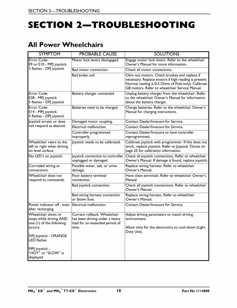
All Power WheelchairsSYMPTOM PROBABLE CAUSE SOLUTIONS
Error Code:E9 or E10 - MPJ joystick3 flashes - DPJ joystick
Motor lock levers disengaged. Engage motor lock levers. Refer to the wheelchair Owner’s Manual for more information.
Bad motor connection. Check all motor connections.Bad brake coil. Ohm out motors. Check brushes and replace if
necessary. Replace motors if high reading is present. Normal reading is 0-5 Ohms (4 Pole only). Calibrate GB motors. Refer to wheelchair Service Manual.
Error Code:E28 - MPJ joystick5 flashes - DPJ joystick
Battery charger connected. Unplug battery charger from the wheelchair. Refer to the wheelchair Owner’s Manual for information about the battery charger.
Error Code:E14 - MPJ joystick5 flashes - DPJ joystick
Batteries need to be charged. Charge batteries. Refer to the wheelchair Owner’s Manual for charging instructions.
Joystick erratic or does not respond as desired.
Damaged motor coupling. Contact Dealer/Invacare for Service.Electrical malfunction. Contact Dealer/Invacare for Service.Controller programmed improperly.
Contact Dealer/Invacare to have controller reprogrammed.
Wheelchair veers to the left or right when driving on level surface.
Joystick needs to be calibrated. Calibrate joystick with programmer. If this does not work, replace joystick. Refer to Joystick Throw on page 25 for calibration information.
No LED’s on joystick. Joystick connection to controller unplugged or damaged.
Check all joystick connections. Refer to wheelchair Owner’s Manual. If damage is found, replace joystick.
Corroded wiring or connections.
Possible water, salt, or urine damage.
Replace wiring harness. Refer to wheelchair Owner’s Manual.
Wheelchair does not respond to commands.
Poor battery terminal connection.
Have clean terminals. Refer to wheelchair Owner’s Manual.
Bad joystick connection. Check all joystick connections. Refer to wheelchair Owner’s Manual.
Bad wiring harness connection or blown fuse.
Replace wiring harness. Refer to wheelchair Owner’s Manual.
Power indicator off - even after recharging.
Electrical malfunction. Contact Dealer/Invacare for Service.
Wheelchair slows or stops while driving AND one (1) of the following occurs:
DPJ Joystick - ORANGE LED flashes
MPJ Joystick - “HOT” or “SLOW” is displayed
Current rollback. Wheelchair has been driving under a heavy load for an extended period of time.
Adjust driving parameters to match driving environment.
Allow time for the electronics to cool down (Light Duty Use).
MK5™EX™ and MK5
™TT-EX™ Electronics 10 Part No 1114808
SECTION 2—TROUBLESHOOTING
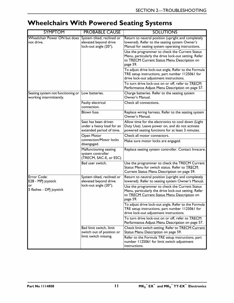
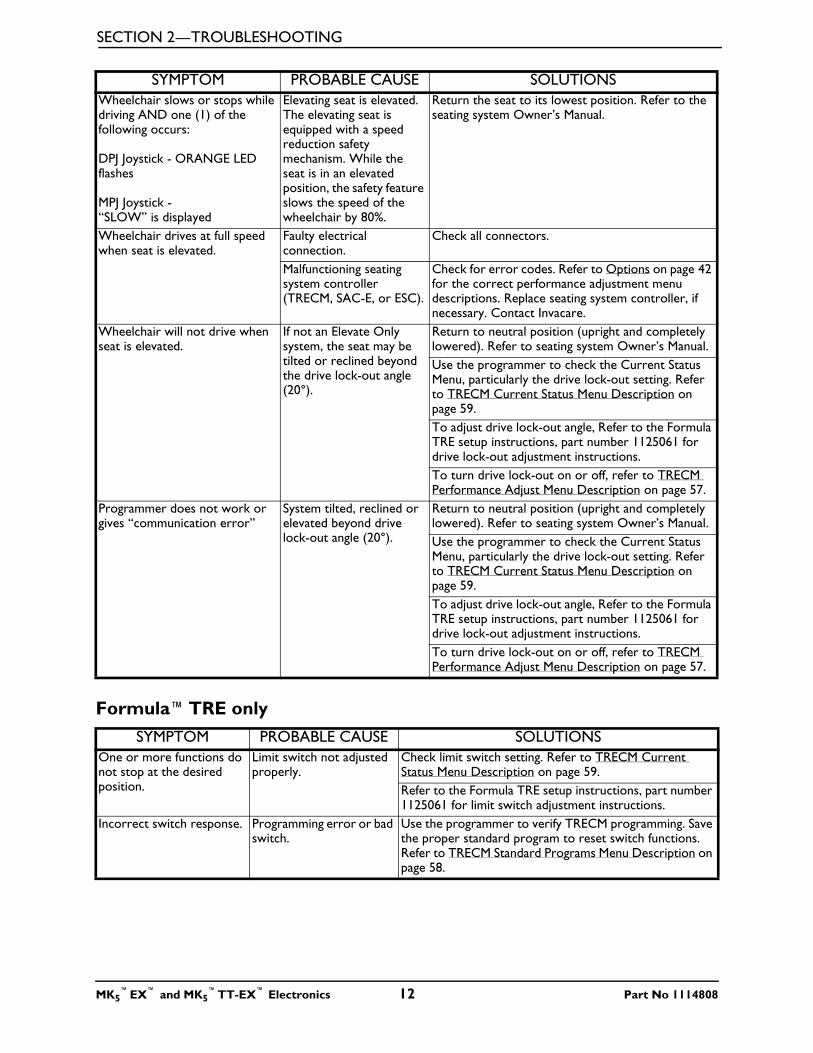
Wheelchairs With Powered Seating SystemsSYMPTOM PROBABLE CAUSE SOLUTIONS
Wheelchair Power ON but does not drive.
System tilted, reclined or elevated beyond drive lock-out angle (20°).
Return to neutral position (upright and completely lowered). Refer to the seating system Owner’s Manual for seating system operating instructions.Use the programmer to check the Current Status Menu, particularly the drive lock-out setting. Refer to TRECM Current Status Menu Description on page 59.To adjust drive lock-out angle, Refer to the Formula TRE setup instructions, part number 1125061 for drive lock-out adjustment instructions.To turn drive lock-out on or off, refer to TRECM Performance Adjust Menu Description on page 57.
Seating system not functioning or working intermittently.
Low batteries. Charge batteries. Refer to the seating system Owner’s Manual.
Faulty electrical connection.
Check all connections.
Blown fuse. Replace wiring harness. Refer to the seating system Owner’s Manual.
Seat has been driven under a heavy load for an extended period of time.
Allow time for the electronics to cool down (Light Duty Use). Leave power on, and do not activate powered seating functions for at least 3 minutes.
Open Motor connection/Motor locks disengaged.
Check all motor connectors.Make sure motor locks are engaged.
Malfunctioning seating system controller (TRECM, SAC-E, or ESC).
Replace seating system controller. Contact Invacare.
Bad user switch. Use the programmer to check the TRECM Current Status Menu for switch status. Refer to TRECM Current Status Menu Description on page 59.
Error Code:E28 - MPJ joystickor5 flashes - DPJ joystick
System tilted, reclined or elevated beyond drive lock-out angle (20°).
Return to neutral position (upright and completely lowered). Refer to seating system Owner’s Manual.Use the programmer to check the Current Status Menu, particularly the drive lock-out setting. Refer to TRECM Current Status Menu Description on page 59.To adjust drive lock-out angle, Refer to the Formula TRE setup instructions, part number 1125061 for drive lock-out adjustment instructions.To turn drive lock-out on or off, refer to TRECM Performance Adjust Menu Description on page 57.
Bad limit switch, limit switch out of position or limit switch missing.
Check limit switch setting. Refer to TRECM Current Status Menu Description on page 59.Refer to the Formula TRE setup instructions, part number 1125061 for limit switch adjustment instructions.
Part No 1114808 11 MK5™EX™ and MK5
™TT-EX™ Electronics
SECTION 2—TROUBLESHOOTING
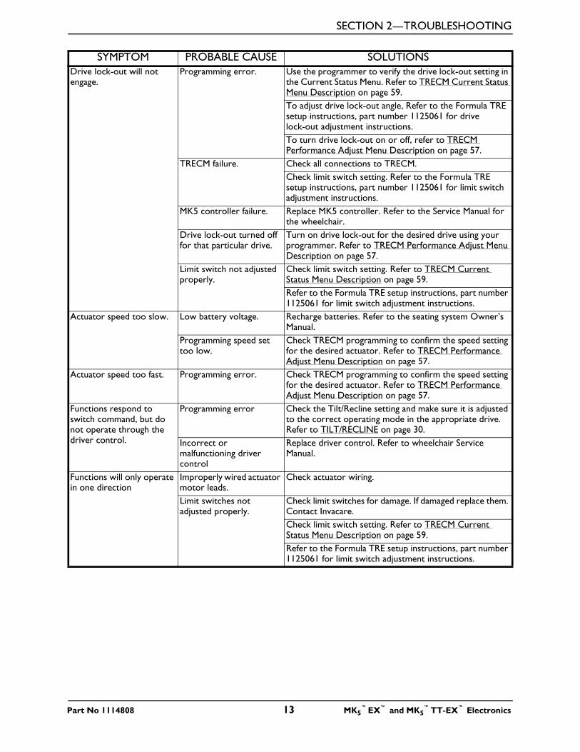
Formula™TRE only
Wheelchair slows or stops while driving AND one (1) of the following occurs:
DPJ Joystick - ORANGE LED flashes
MPJ Joystick - “SLOW” is displayed
Elevating seat is elevated. The elevating seat is equipped with a speed reduction safety mechanism. While the seat is in an elevated position, the safety feature slows the speed of the wheelchair by 80%.
Return the seat to its lowest position. Refer to the seating system Owner’s Manual.
Wheelchair drives at full speed when seat is elevated.
Faulty electrical connection.
Check all connectors.
Malfunctioning seating system controller (TRECM, SAC-E, or ESC).
Check for error codes. Refer to Options on page 42 for the correct performance adjustment menu descriptions. Replace seating system controller, if necessary. Contact Invacare.
Wheelchair will not drive when seat is elevated.
If not an Elevate Only system, the seat may be tilted or reclined beyond the drive lock-out angle (20°).
Return to neutral position (upright and completely lowered). Refer to seating system Owner’s Manual.Use the programmer to check the Current Status Menu, particularly the drive lock-out setting. Refer to TRECM Current Status Menu Description on page 59.To adjust drive lock-out angle, Refer to the Formula TRE setup instructions, part number 1125061 for drive lock-out adjustment instructions.To turn drive lock-out on or off, refer to TRECM Performance Adjust Menu Description on page 57.
Programmer does not work or gives “communication error”
System tilted, reclined or elevated beyond drive lock-out angle (20°).
Return to neutral position (upright and completely lowered). Refer to seating system Owner’s Manual.Use the programmer to check the Current Status Menu, particularly the drive lock-out setting. Refer to TRECM Current Status Menu Description on page 59.To adjust drive lock-out angle, Refer to the Formula TRE setup instructions, part number 1125061 for drive lock-out adjustment instructions.To turn drive lock-out on or off, refer to TRECM Performance Adjust Menu Description on page 57.
SYMPTOM PROBABLE CAUSE SOLUTIONSOne or more functions do not stop at the desired position.
Limit switch not adjusted properly.
Check limit switch setting. Refer to TRECM Current Status Menu Description on page 59.Refer to the Formula TRE setup instructions, part number 1125061 for limit switch adjustment instructions.
Incorrect switch response. Programming error or bad switch.
Use the programmer to verify TRECM programming. Save the proper standard program to reset switch functions. Refer to TRECM Standard Programs Menu Description on page 58.
SYMPTOM PROBABLE CAUSE SOLUTIONS
MK5™EX™ and MK5
™TT-EX™ Electronics 12 Part No 1114808
SECTION 2—TROUBLESHOOTING
Drive lock-out will not engage.
Programming error. Use the programmer to verify the drive lock-out setting in the Current Status Menu. Refer to TRECM Current Status Menu Description on page 59.To adjust drive lock-out angle, Refer to the Formula TRE setup instructions, part number 1125061 for drive lock-out adjustment instructions.To turn drive lock-out on or off, refer to TRECM Performance Adjust Menu Description on page 57.
TRECM failure. Check all connections to TRECM.Check limit switch setting. Refer to the Formula TRE setup instructions, part number 1125061 for limit switch adjustment instructions.
MK5 controller failure. Replace MK5 controller. Refer to the Service Manual for the wheelchair.
Drive lock-out turned off for that particular drive.
Turn on drive lock-out for the desired drive using your programmer. Refer to TRECM Performance Adjust Menu Description on page 57.
Limit switch not adjusted properly.
Check limit switch setting. Refer to TRECM Current Status Menu Description on page 59.Refer to the Formula TRE setup instructions, part number 1125061 for limit switch adjustment instructions.
Actuator speed too slow. Low battery voltage. Recharge batteries. Refer to the seating system Owner’s Manual.
Programming speed set too low.
Check TRECM programming to confirm the speed setting for the desired actuator. Refer to TRECM Performance Adjust Menu Description on page 57.
Actuator speed too fast. Programming error. Check TRECM programming to confirm the speed setting for the desired actuator. Refer to TRECM Performance Adjust Menu Description on page 57.
Functions respond to switch command, but do not operate through the driver control.
Programming error Check the Tilt/Recline setting and make sure it is adjusted to the correct operating mode in the appropriate drive. Refer to TILT/RECLINE on page 30.
Incorrect or malfunctioning driver control
Replace driver control. Refer to wheelchair Service Manual.
Functions will only operate in one direction
Improperly wired actuator motor leads.
Check actuator wiring.
Limit switches not adjusted properly.
Check limit switches for damage. If damaged replace them. Contact Invacare.Check limit switch setting. Refer to TRECM Current Status Menu Description on page 59.Refer to the Formula TRE setup instructions, part number 1125061 for limit switch adjustment instructions.
SYMPTOM PROBABLE CAUSE SOLUTIONS
Part No 1114808 13 MK5™EX™ and MK5
™TT-EX™ Electronics
SECTION 3—JOYSTICK DESCRIPTIONS
SECTION 3—JOYSTICK DESCRIPTIONS
Joystick OverviewThere are two (2) standard joysticks which make up the MK5 system. The two (2) joystick types are the DPJ™ and MPJ™. The joysticks differ in user controls, switches, number of programmable drives and performance adjustments. The joysticks provide proportional drive control of speed and direction.
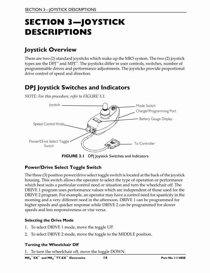
DPJ Joystick Switches and IndicatorsNOTE: For this procedure, refer to FIGURE 3.1.
FIGURE 3.1 DPJ Joystick Switches and Indicators
Power/Drive Select Toggle Switch
The three (3) position power/drive select toggle switch is located at the back of the joystick housing. This switch allows the operator to select the type of operation or performance which best suits a particular control need or situation and turn the wheelchair off. The DRIVE 1 program uses performance values which are independent of those used for the DRIVE 2 program. For example, an operator may have a control need for spasticity in the morning and a very different need in the afternoon. DRIVE 1 can be programmed for higher speeds and quicker response while DRIVE 2 can be programmed for slower speeds and less responsiveness or vise versa.
Selecting the Drive Mode
1. To select DRIVE 1 mode, move the toggle UP.
2. To select DRIVE 2 mode, move the toggle to the MIDDLE position.
Turning the Wheelchair Off
1. To turn the wheelchair off, move the toggle DOWN.
Mode Switch
Battery Gauge Display
Power/Drive Select Toggle Switch
Speed Control Knob
To Controller
Joystick
Charger/Programming Port
MK5™EX™ and MK5
™TT-EX™ Electronics 14 Part No 1114808
SECTION 3—JOYSTICK DESCRIPTIONS
Speed Control Knob
The speed control knob is located at the back of the joystick housing.
1. Turn the knob clockwise to increase the maximum speed of the wheelchair.
2. Turn the knob counterclockwise to decrease the maximum speed of the wheelchair.
Mode (On/Off) Switch
The mode (on/off) switch is a push button switch located at the front of the joystick. When an optional actuator control [Single Actuator control, (SAC), Two Actuator Control (TAC) or Tilt and Recline Control Module (TRCM)] is present, pushing the switch will change the controller mode to control the optional actuators through the joystick. The mode switch LED indicator will be ON. Push the switch again to return to normal joystick driving. The mode switch LED indicator will be off.
Battery Gauge Display (BGD)
Located at the rear of the joystick housing, the BGD provides information on the remaining charge in the batteries. At full charge, all six (6) segments of the bar graph are lit. As the battery discharges, the farthest right (GREEN) segment will go out until only the red bar is lit. At this level, the last red bar will start to flash on and off to indicate that the user should charge the batteries as soon as possible.
The BGD also serves as a system diagnostic device when a fault is detected by the control module. A specific number of flashes (up to eight (8) flashes) of the two (2) RED bars separated by a pause will indicate the type of fault detected. A chart of the diagnostic indications is given in Diagnostic Codes on page 38.
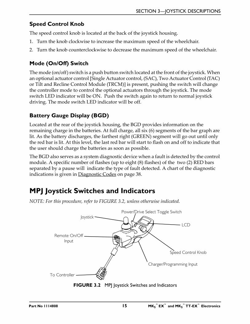
MPJ Joystick Switches and IndicatorsNOTE: For this procedure, refer to FIGURE 3.2, unless otherwise indicated.
FIGURE 3.2 MPJ Joystick Switches and Indicators
Joystick
Remote On/Off Input
To Controller
Power/Drive Select Toggle Switch
LCD
Speed Control Knob
Charger/Programming Input
Part No 1114808 15 MK5™EX™ and MK5
™TT-EX™ Electronics
SECTION 3—JOYSTICK DESCRIPTIONS
Power/Drive Select Toggle Switch
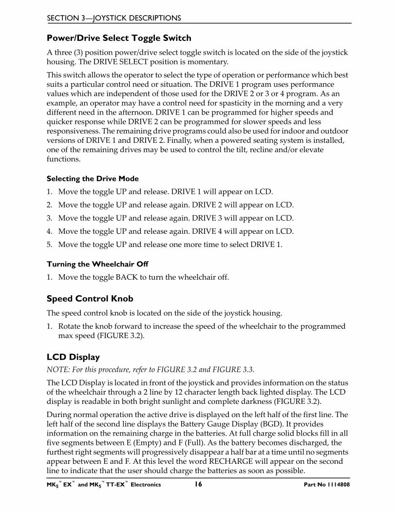
A three (3) position power/drive select toggle switch is located on the side of the joystick housing. The DRIVE SELECT position is momentary.
This switch allows the operator to select the type of operation or performance which best suits a particular control need or situation. The DRIVE 1 program uses performance values which are independent of those used for the DRIVE 2 or 3 or 4 program. As an example, an operator may have a control need for spasticity in the morning and a very different need in the afternoon. DRIVE 1 can be programmed for higher speeds and quicker response while DRIVE 2 can be programmed for slower speeds and less responsiveness. The remaining drive programs could also be used for indoor and outdoor versions of DRIVE 1 and DRIVE 2. Finally, when a powered seating system is installed, one of the remaining drives may be used to control the tilt, recline and/or elevate functions.
Selecting the Drive Mode
1. Move the toggle UP and release. DRIVE 1 will appear on LCD.
2. Move the toggle UP and release again. DRIVE 2 will appear on LCD.
3. Move the toggle UP and release again. DRIVE 3 will appear on LCD.
4. Move the toggle UP and release again. DRIVE 4 will appear on LCD.
5. Move the toggle UP and release one more time to select DRIVE 1.
Turning the Wheelchair Off
1. Move the toggle BACK to turn the wheelchair off.
Speed Control Knob
The speed control knob is located on the side of the joystick housing.
1. Rotate the knob forward to increase the speed of the wheelchair to the programmed max speed (FIGURE 3.2).
LCD DisplayNOTE: For this procedure, refer to FIGURE 3.2 and FIGURE 3.3.
The LCD Display is located in front of the joystick and provides information on the status of the wheelchair through a 2 line by 12 character length back lighted display. The LCD display is readable in both bright sunlight and complete darkness (FIGURE 3.2).
During normal operation the active drive is displayed on the left half of the first line. The left half of the second line displays the Battery Gauge Display (BGD). It provides information on the remaining charge in the batteries. At full charge solid blocks fill in all five segments between E (Empty) and F (Full). As the battery becomes discharged, the furthest right segments will progressively disappear a half bar at a time until no segments appear between E and F. At this level the word RECHARGE will appear on the second line to indicate that the user should charge the batteries as soon as possible.
MK5™EX™ and MK5
™TT-EX™ Electronics 16 Part No 1114808
SECTION 3—JOYSTICK DESCRIPTIONS
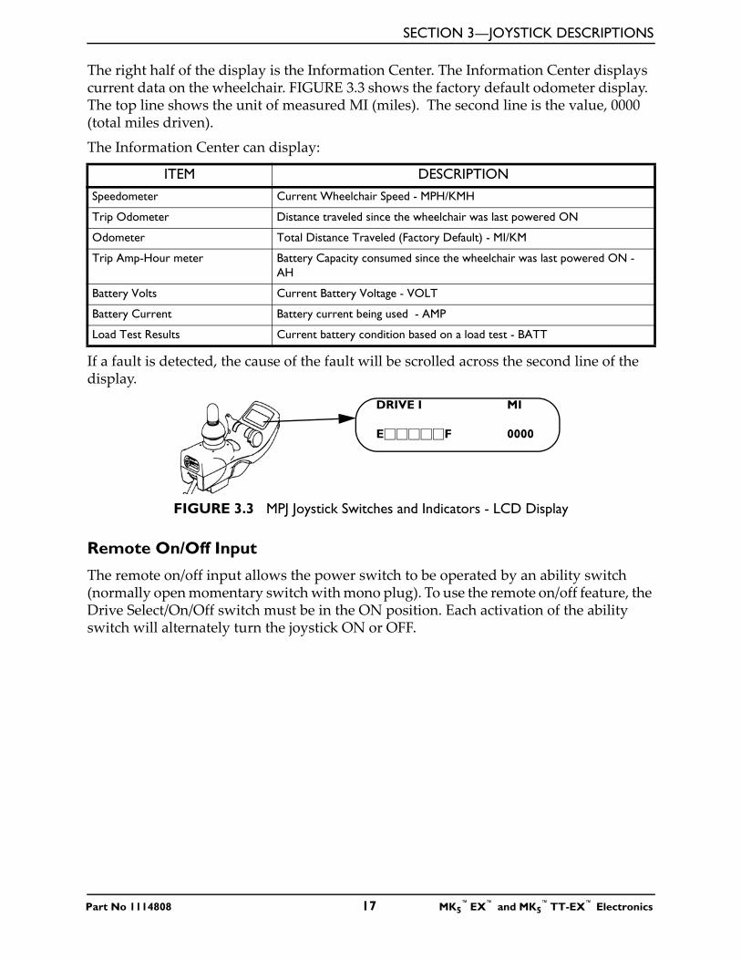
The right half of the display is the Information Center. The Information Center displays current data on the wheelchair. FIGURE 3.3 shows the factory default odometer display. The top line shows the unit of measured MI (miles). The second line is the value, 0000 (total miles driven).
The Information Center can display:
If a fault is detected, the cause of the fault will be scrolled across the second line of the display.
FIGURE 3.3 MPJ Joystick Switches and Indicators - LCD Display
Remote On/Off Input
The remote on/off input allows the power switch to be operated by an ability switch (normally open momentary switch with mono plug). To use the remote on/off feature, the Drive Select/On/Off switch must be in the ON position. Each activation of the ability switch will alternately turn the joystick ON or OFF.
ITEM DESCRIPTIONSpeedometer Current Wheelchair Speed - MPH/KMH
Trip Odometer Distance traveled since the wheelchair was last powered ON
Odometer Total Distance Traveled (Factory Default) - MI/KM
Trip Amp-Hour meter Battery Capacity consumed since the wheelchair was last powered ON - AH
Battery Volts Current Battery Voltage - VOLT
Battery Current Battery current being used - AMP
Load Test Results Current battery condition based on a load test - BATT
DRIVE I MI
E�����F 0000
Part No 1114808 17 MK5™EX™ and MK5
™TT-EX™ Electronics
SECTION 4—REMOTE PROGRAMMER
SECTION 4—REMOTE PROGRAMMER
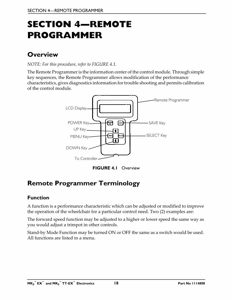
OverviewNOTE: For this procedure, refer to FIGURE 4.1.
The Remote Programmer is the information center of the control module. Through simple key sequences, the Remote Programmer allows modification of the performance characteristics, gives diagnostics information for trouble shooting and permits calibration of the control module.
FIGURE 4.1 Overview
Remote Programmer Terminology
Function
A function is a performance characteristic which can be adjusted or modified to improve the operation of the wheelchair for a particular control need. Two (2) examples are:
The forward speed function may be adjusted to a higher or lower speed the same way as you would adjust a trimpot in other controls.
Stand-by Mode Function may be turned ON or OFF the same as a switch would be used. All functions are listed in a menu.
SAVE Key
SELECT Key
POWER Key
MENU Key
To Controller
DOWN Key
UP Key
LCD Display
Remote Programmer
MK5™EX™ and MK5
™TT-EX™ Electronics 18 Part No 1114808
SECTION 4—REMOTE PROGRAMMER
Value
Each function has a value. It is the degree or amount of the function which is used to influence the overall wheelchair performance. Most values are numerical or in percentages, for instance - high speed may be set to 75% of the wheelchair's maximum. For others, the value is either ON or OFF, for example - Stand-by Mode. Changing a value is called Adjustment.
Standard Program (Preset Programs)
The standard programs are fixed function values which are used as an initial set up point from which individualization of the wheelchair performance can begin. Standard values are NEVER altered or modified.
User Memory Values
The user memory values can only be changed through the Remote Programmer by first modifying the temporary memory values and then by saving them in the user memory where they become the user program. The Remote Programmer is activated by pressing the POWER key when the wheelchair is in neutral. The wheelchair cannot be driven when the LCD display is illuminated. The display will automatically turn itself OFF after 45 seconds if no keys are pressed. It can also be turned OFF by pressing the POWER key.
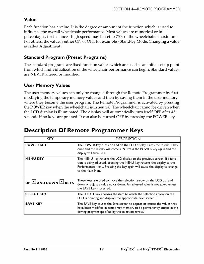
Description Of Remote Programmer KeysKEY DESCRIPTION
POWER KEY The POWER key turns on and off the LCD display. Press the POWER key once and the display will come ON. Press the POWER key again and the display will turn OFF.
MENU KEY The MENU key returns the LCD display to the previous screen. If a func-tion is being adjusted, pressing the MENU key returns the display to the Performance Menu. Pressing the key again will cause the display to change to the Main Menu.
UP AND DOWN KEYS These keys are used to move the selection arrow on the LCD up and down or adjust a value up or down. An adjusted value is not saved unless the SAVE key is pressed.
SELECT KEY The SELECT key chooses the item to which the selection arrow on the LCD is pointing and displays the appropriate next screen.
SAVE KEY The SAVE key causes the Save screen to appear or causes the values that have been modified in temporary memory to be permanently stored in the driving program specified by the selection arrow.
Part No 1114808 19 MK5™EX™ and MK5
™TT-EX™ Electronics
SECTION 5—PERFORMANCE ADJUSTMENTS
SECTION 5—PERFORMANCE ADJUSTMENTS
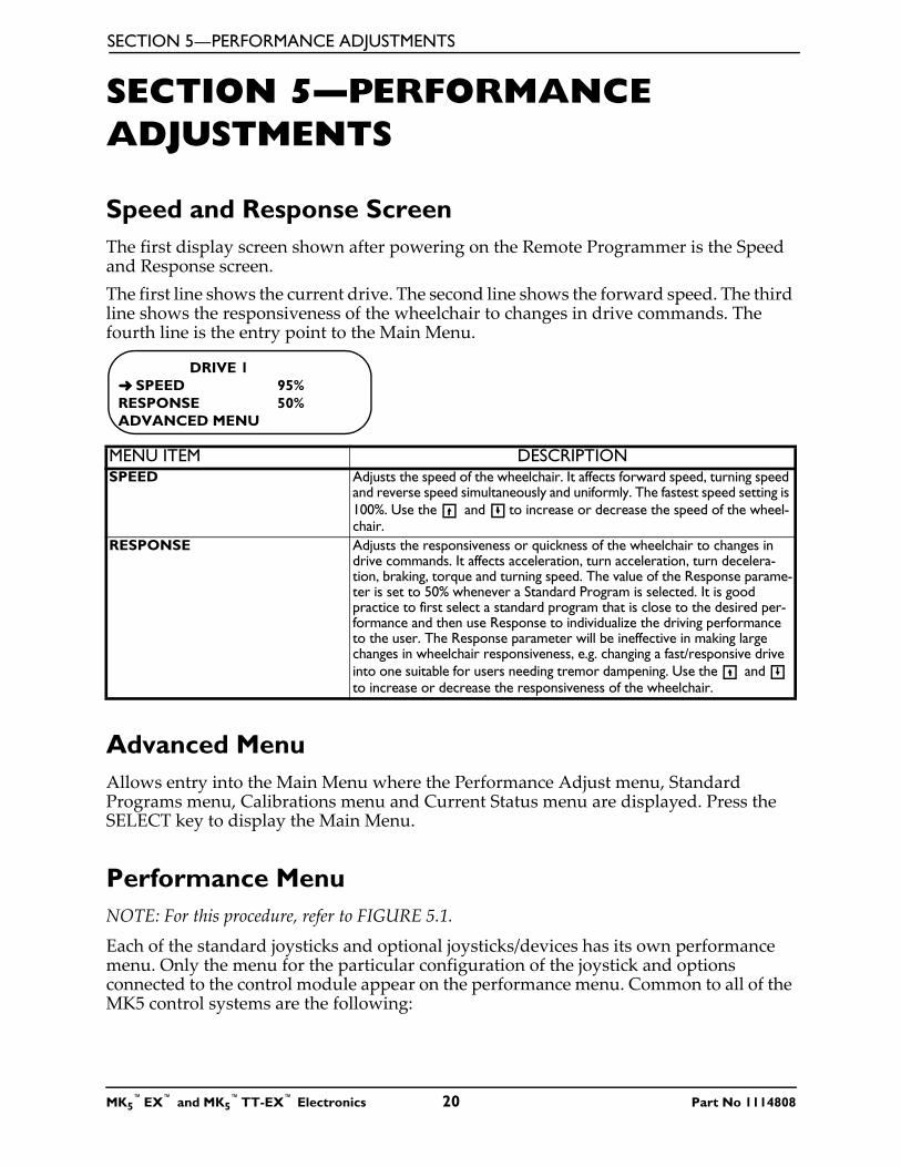
Speed and Response ScreenThe first display screen shown after powering on the Remote Programmer is the Speed and Response screen.The first line shows the current drive. The second line shows the forward speed. The third line shows the responsiveness of the wheelchair to changes in drive commands. The fourth line is the entry point to the Main Menu.
Advanced MenuAllows entry into the Main Menu where the Performance Adjust menu, Standard Programs menu, Calibrations menu and Current Status menu are displayed. Press the SELECT key to display the Main Menu.
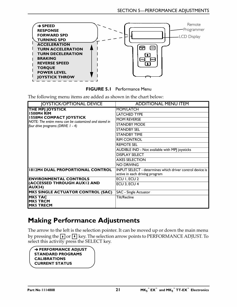
Performance MenuNOTE: For this procedure, refer to FIGURE 5.1.
Each of the standard joysticks and optional joysticks/devices has its own performance menu. Only the menu for the particular configuration of the joystick and options connected to the control module appear on the performance menu. Common to all of the MK5 control systems are the following:
MENU ITEM DESCRIPTIONSPEED Adjusts the speed of the wheelchair. It affects forward speed, turning speed
and reverse speed simultaneously and uniformly. The fastest speed setting is 100%. Use the and to increase or decrease the speed of the wheel-chair.
RESPONSE Adjusts the responsiveness or quickness of the wheelchair to changes in drive commands. It affects acceleration, turn acceleration, turn decelera-tion, braking, torque and turning speed. The value of the Response parame-ter is set to 50% whenever a Standard Program is selected. It is good practice to first select a standard program that is close to the desired per-formance and then use Response to individualize the driving performance to the user. The Response parameter will be ineffective in making large changes in wheelchair responsiveness, e.g. changing a fast/responsive drive into one suitable for users needing tremor dampening. Use the and to increase or decrease the responsiveness of the wheelchair.
DRIVE 1 ➜ SPEED 95%RESPONSE 50%ADVANCED MENU
MK5™EX™ and MK5
™TT-EX™ Electronics 20 Part No 1114808
SECTION 5—PERFORMANCE ADJUSTMENTS
FIGURE 5.1 Performance Menu
The following menu items are added as shown in the chart below:
Making Performance AdjustmentsThe arrow to the left is the selection pointer. It can be moved up or down the main menu by pressing the or key. The selection arrow points to PERFORMANCE ADJUST. To select this activity press the SELECT key.
JOYSTICK/OPTIONAL DEVICE ADDITIONAL MENU ITEMTHE MPJ JOYSTICK1500M4 RIM1558M4 COMPACT JOYSTICKNOTE: The entire menu can be customized and stored in four drive programs (DRIVE 1 - 4)
MOM/LATCHLATCHED TYPEMOM REVERSESTANDBY MODESTANDBY SELSTANDBY TIMERIM CONTROLREMOTE SELAUDIBLE IND - Not available with MPJ joysticksDISPLAY SELECT AXES SELECTIONNO DRIVING
1812M4 DUAL PROPORTIONAL CONTROL INPUT SELECT - determines which driver control device is active in each driving program
ENVIRONMENTAL CONTROLS(ACCESSED THROUGH AUX12 AND AUX34)
ECU 1, ECU 2ECU 3, ECU 4
MK5 SINGLE ACTUATOR CONTROL (SAC) SAC - Single ActuatorMK5 TACMK5 TRCMMK5 TRECM
Tilt/Recline
LCD Display
Remote Programmer
➜ SPEEDRESPONSEFORWARD SPDTURNING SPDACCELERATIONTURN ACCELERATIONTURN DECELERATIONBRAKINGREVERSE SPEEDTORQUEPOWER LEVELJOYSTICK THROW
➜ PERFORMANCE ADJUSTSTANDARD PROGRAMSCALIBRATIONSCURRENT STATUS
Part No 1114808 21 MK5™EX™ and MK5
™TT-EX™ Electronics
SECTION 5—PERFORMANCE ADJUSTMENTS
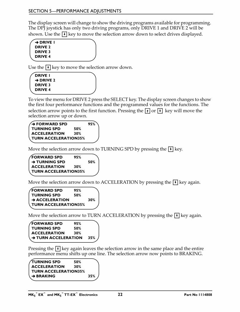
The display screen will change to show the driving programs available for programming. The DPJ joystick has only two driving programs, only DRIVE 1 and DRIVE 2 will be shown. Use the key to move the selection arrow down to select drives displayed.
Use the key to move the selection arrow down.
To view the menu for DRIVE 2 press the SELECT key. The display screen changes to show the first four performance functions and the programmed values for the functions. The selection arrow points to the first function. Pressing the or key will move the selection arrow up or down.
Move the selection arrow down to TURNING SPD by pressing the key.
Move the selection arrow down to ACCELERATION by pressing the key again.
Move the selection arrow to TURN ACCELERATION by pressing the key again.
Pressing the key again leaves the selection arrow in the same place and the entire performance menu shifts up one line. The selection arrow now points to BRAKING.
➜ DRIVE 1DRIVE 2DRIVE 3DRIVE 4
DRIVE 1➜ DRIVE 2DRIVE 3DRIVE 4
➜ FORWARD SPD 95%TURNING SPD 50%ACCELERATION 30%TURN ACCELERATION35%
FORWARD SPD 95%➜ TURNING SPD 50%ACCELERATION 30%TURN ACCELERATION35%
FORWARD SPD 95%TURNING SPD 50%➜ ACCELERATION 30%TURN ACCELERATION35%
FORWARD SPD 95%TURNING SPD 50%ACCELERATION 30%➜ TURN ACCELERATION 35%
TURNING SPD 50%ACCELERATION 30%TURN ACCELERATION35%➜ BRAKING 35%
MK5™EX™ and MK5
™TT-EX™ Electronics 22 Part No 1114808
SECTION 5—PERFORMANCE ADJUSTMENTS
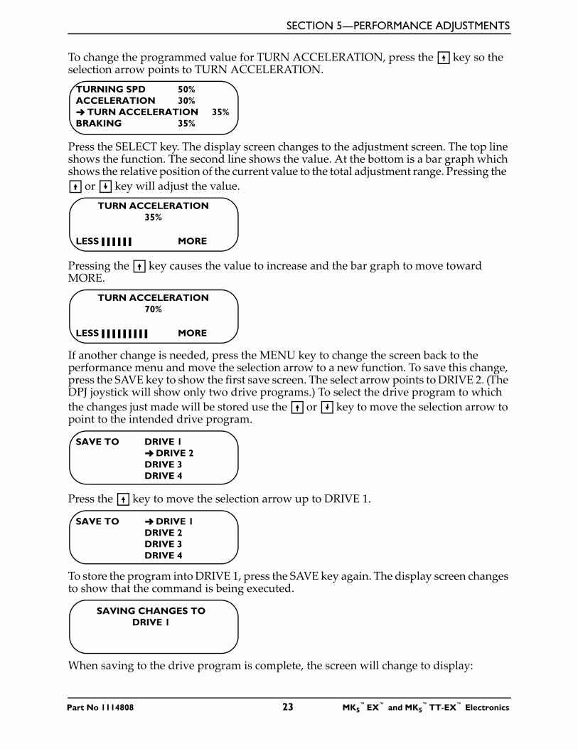
To change the programmed value for TURN ACCELERATION, press the key so the selection arrow points to TURN ACCELERATION.
Press the SELECT key. The display screen changes to the adjustment screen. The top line shows the function. The second line shows the value. At the bottom is a bar graph which shows the relative position of the current value to the total adjustment range. Pressing the
or key will adjust the value.
Pressing the key causes the value to increase and the bar graph to move toward MORE.
If another change is needed, press the MENU key to change the screen back to the performance menu and move the selection arrow to a new function. To save this change, press the SAVE key to show the first save screen. The select arrow points to DRIVE 2. (The DPJ joystick will show only two drive programs.) To select the drive program to which the changes just made will be stored use the or key to move the selection arrow to point to the intended drive program.
Press the key to move the selection arrow up to DRIVE 1.
To store the program into DRIVE 1, press the SAVE key again. The display screen changes to show that the command is being executed.
When saving to the drive program is complete, the screen will change to display:
TURNING SPD 50%ACCELERATION 30%➜ TURN ACCELERATION 35%BRAKING 35%
TURN ACCELERATION35%
LESS MORE
TURN ACCELERATION70%
LESS MORE
SAVE TO DRIVE 1➜ DRIVE 2DRIVE 3DRIVE 4
SAVE TO ➜ DRIVE 1DRIVE 2DRIVE 3DRIVE 4
SAVING CHANGES TO DRIVE 1
Part No 1114808 23 MK5™EX™ and MK5
™TT-EX™ Electronics
SECTION 5—PERFORMANCE ADJUSTMENTS
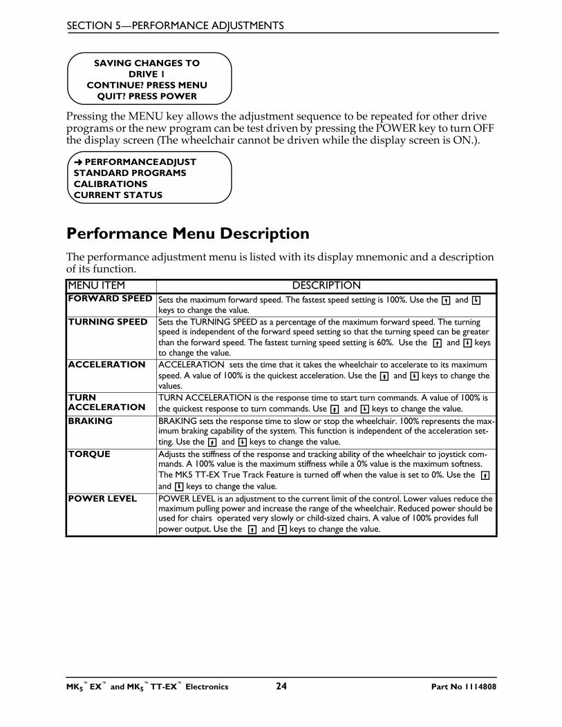
Pressing the MENU key allows the adjustment sequence to be repeated for other drive programs or the new program can be test driven by pressing the POWER key to turn OFF the display screen (The wheelchair cannot be driven while the display screen is ON.).
Performance Menu DescriptionThe performance adjustment menu is listed with its display mnemonic and a description of its function.MENU ITEM DESCRIPTIONFORWARD SPEED Sets the maximum forward speed. The fastest speed setting is 100%. Use the and
keys to change the value.TURNING SPEED Sets the TURNING SPEED as a percentage of the maximum forward speed. The turning
speed is independent of the forward speed setting so that the turning speed can be greater than the forward speed. The fastest turning speed setting is 60%. Use the and keys to change the value.
ACCELERATION ACCELERATION sets the time that it takes the wheelchair to accelerate to its maximum speed. A value of 100% is the quickest acceleration. Use the and keys to change the values.
TURN ACCELERATION
TURN ACCELERATION is the response time to start turn commands. A value of 100% is the quickest response to turn commands. Use and keys to change the value.
BRAKING BRAKING sets the response time to slow or stop the wheelchair. 100% represents the max-imum braking capability of the system. This function is independent of the acceleration set-ting. Use the and keys to change the value.
TORQUE Adjusts the stiffness of the response and tracking ability of the wheelchair to joystick com-mands. A 100% value is the maximum stiffness while a 0% value is the maximum softness. The MK5 TT-EX True Track Feature is turned off when the value is set to 0%. Use the and keys to change the value.
POWER LEVEL POWER LEVEL is an adjustment to the current limit of the control. Lower values reduce the maximum pulling power and increase the range of the wheelchair. Reduced power should be used for chairs operated very slowly or child-sized chairs. A value of 100% provides full power output. Use the and keys to change the value.
SAVING CHANGES TO DRIVE 1
CONTINUE? PRESS MENUQUIT? PRESS POWER
➜ PERFORMANCE ADJUST STANDARD PROGRAMSCALIBRATIONSCURRENT STATUS
MK5™EX™ and MK5
™TT-EX™ Electronics 24 Part No 1114808
SECTION 5—PERFORMANCE ADJUSTMENTS
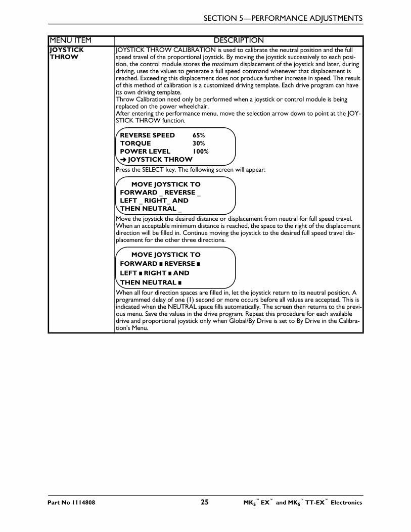
JOYSTICK THROW
JOYSTICK THROW CALIBRATION is used to calibrate the neutral position and the full speed travel of the proportional joystick. By moving the joystick successively to each posi-tion, the control module stores the maximum displacement of the joystick and later, during driving, uses the values to generate a full speed command whenever that displacement is reached. Exceeding this displacement does not produce further increase in speed. The result of this method of calibration is a customized driving template. Each drive program can have its own driving template. Throw Calibration need only be performed when a joystick or control module is being replaced on the power wheelchair. After entering the performance menu, move the selection arrow down to point at the JOY-STICK THROW function.
Press the SELECT key. The following screen will appear:
Move the joystick the desired distance or displacement from neutral for full speed travel. When an acceptable minimum distance is reached, the space to the right of the displacement direction will be filled in. Continue moving the joystick to the desired full speed travel dis-placement for the other three directions.
When all four direction spaces are filled in, let the joystick return to its neutral position. A programmed delay of one (1) second or more occurs before all values are accepted. This is indicated when the NEUTRAL space fills automatically. The screen then returns to the previ-ous menu. Save the values in the drive program. Repeat this procedure for each available drive and proportional joystick only when Global/By Drive is set to By Drive in the Calibra-tion's Menu.
MENU ITEM DESCRIPTION
REVERSE SPEED 65% TORQUE 30%POWER LEVEL 100%➜ JOYSTICK THROW
MOVE JOYSTICK TO FORWARD _ REVERSE _LEFT _ RIGHT_ ANDTHEN NEUTRAL _
MOVE JOYSTICK TO FORWARD REVERSE LEFT RIGHT ANDTHEN NEUTRAL
Part No 1114808 25 MK5™EX™ and MK5
™TT-EX™ Electronics
SECTION 5—PERFORMANCE ADJUSTMENTS
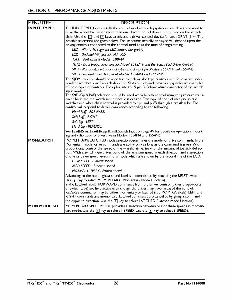
INPUT TYPE? The INPUT TYPE function tells the control module which joystick or switch is to be used to drive the wheelchair when more than one driver control device is mounted on the wheel-chair. Use the and keys to select the driver control device for each DRIVE (1-4). The possible selections are given below. The selections actually displayed will depend upon the driving controls connected to the control module at the time of programming.
LED - With a 10 segment LED battery bar graph.LCD - Optional MPJ joystick with LCD.1500 - RIM control Model 1500M4.1812 - Dual proportional joystick Model 1812M4 and the Touch Pad Driver Control.SJOY - Microswitch input or slot type control input for Models 1554M4 and 1554M5. S&P - Pneumatic switch input of Models 1554M4 and 1554M5.
The SJOY selection should be used for joystick or slot type controls with four or five inde-pendent switches, one for each direction. Slot controls and miniature joysticks are examples of these types of controls. They plug into the 9 pin D-Subminiature connector of the switch input module.The S&P (Sip & Puff) selection should be used when breath control using the pressure trans-ducer built into the switch input module is desired. This type of control uses pneumatic switches and wheelchair control is provided by sips and puffs through a breath tube. The control will respond to driver commands according to the following:
Hard Puff - FORWARDSoft Puff - RIGHTSoft Sip - LEFTHard Sip - REVERSE
See 1554M5 or 1554M4 Sip & Puff Switch Input on page 49 for details on operation, mount-ing and calibration of pressures in Models 1554M4 and 1554M5.
MOM/LATCH MOMENTARY/LATCHED mode selection determines the mode for drive commands. In the Momentary mode, drive commands are active only as long as the command is given. With proportional control the speed of the wheelchair varies with the amount of joystick deflec-tion. With a switch type driver control, there is one speed in each direction and a selection of one or three speed levels in this mode which are shown by the second line of the LCD.
LOW SPEED - Lowest speedMED SPEED - Medium speedNORMAL DISPLAY - Fastest speed
Advancing to the next highest speed level is accomplished by actuating the RESET switch. Use key to select MOMENTARY (Momentary Mode Function).In the Latched mode, FORWARD commands from the driver control (either proportional or switch type) are held active even though the driver may have released the control. REVERSE commands may be either momentary or latched (see MOM REVERSE). LEFT and RIGHT commands are momentary. Latched commands are cancelled by giving a command in the opposite direction. Use the key to select LATCHED (Latched mode function).
MOM MODE SEL MOMENTARY SPEED MODE provides a selection between one or three speeds in Momen-tary mode. Use the key to select 1 SPEED. Use the key to select 3 SPEEDS.
MENU ITEM DESCRIPTION
MK5™EX™ and MK5
™TT-EX™ Electronics 26 Part No 1114808
SECTION 5—PERFORMANCE ADJUSTMENTS
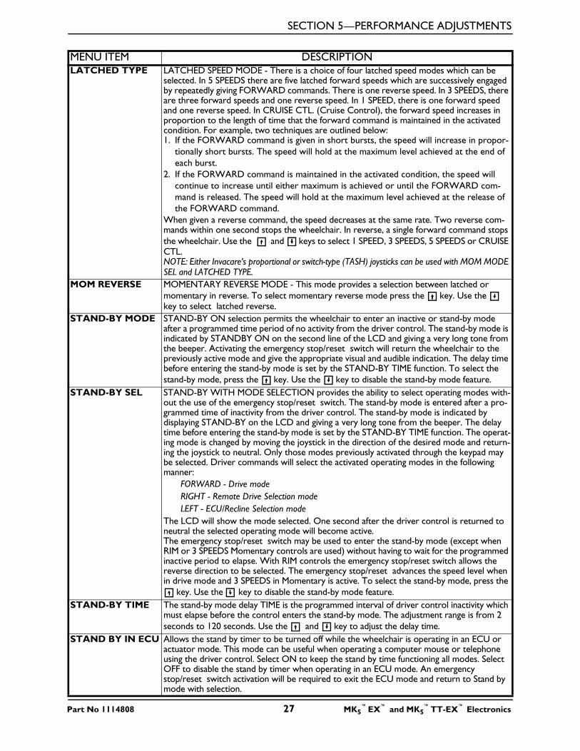
LATCHED TYPE LATCHED SPEED MODE - There is a choice of four latched speed modes which can be selected. In 5 SPEEDS there are five latched forward speeds which are successively engaged by repeatedly giving FORWARD commands. There is one reverse speed. In 3 SPEEDS, there are three forward speeds and one reverse speed. In 1 SPEED, there is one forward speed and one reverse speed. In CRUISE CTL. (Cruise Control), the forward speed increases in proportion to the length of time that the forward command is maintained in the activated condition. For example, two techniques are outlined below:1. If the FORWARD command is given in short bursts, the speed will increase in propor-
tionally short bursts. The speed will hold at the maximum level achieved at the end of each burst.
2. If the FORWARD command is maintained in the activated condition, the speed will continue to increase until either maximum is achieved or until the FORWARD com-mand is released. The speed will hold at the maximum level achieved at the release of the FORWARD command.
When given a reverse command, the speed decreases at the same rate. Two reverse com-mands within one second stops the wheelchair. In reverse, a single forward command stops the wheelchair. Use the and keys to select 1 SPEED, 3 SPEEDS, 5 SPEEDS or CRUISE CTL.NOTE: Either Invacare's proportional or switch-type (TASH) joysticks can be used with MOM MODE SEL and LATCHED TYPE.
MOM REVERSE MOMENTARY REVERSE MODE - This mode provides a selection between latched or momentary in reverse. To select momentary reverse mode press the key. Use the key to select latched reverse.
STAND-BY MODE STAND-BY ON selection permits the wheelchair to enter an inactive or stand-by mode after a programmed time period of no activity from the driver control. The stand-by mode is indicated by STANDBY ON on the second line of the LCD and giving a very long tone from the beeper. Activating the emergency stop/reset switch will return the wheelchair to the previously active mode and give the appropriate visual and audible indication. The delay time before entering the stand-by mode is set by the STAND-BY TIME function. To select the stand-by mode, press the key. Use the key to disable the stand-by mode feature.
STAND-BY SEL STAND-BY WITH MODE SELECTION provides the ability to select operating modes with-out the use of the emergency stop/reset switch. The stand-by mode is entered after a pro-grammed time of inactivity from the driver control. The stand-by mode is indicated by displaying STAND-BY on the LCD and giving a very long tone from the beeper. The delay time before entering the stand-by mode is set by the STAND-BY TIME function. The operat-ing mode is changed by moving the joystick in the direction of the desired mode and return-ing the joystick to neutral. Only those modes previously activated through the keypad may be selected. Driver commands will select the activated operating modes in the following manner:
FORWARD - Drive modeRIGHT - Remote Drive Selection modeLEFT - ECU/Recline Selection mode
The LCD will show the mode selected. One second after the driver control is returned to neutral the selected operating mode will become active.The emergency stop/reset switch may be used to enter the stand-by mode (except when RIM or 3 SPEEDS Momentary controls are used) without having to wait for the programmed inactive period to elapse. With RIM controls the emergency stop/reset switch allows the reverse direction to be selected. The emergency stop/reset advances the speed level when in drive mode and 3 SPEEDS in Momentary is active. To select the stand-by mode, press the
key. Use the key to disable the stand-by mode feature.STAND-BY TIME The stand-by mode delay TIME is the programmed interval of driver control inactivity which
must elapse before the control enters the stand-by mode. The adjustment range is from 2 seconds to 120 seconds. Use the and key to adjust the delay time.
STAND BY IN ECU Allows the stand by timer to be turned off while the wheelchair is operating in an ECU or actuator mode. This mode can be useful when operating a computer mouse or telephone using the driver control. Select ON to keep the stand by time functioning all modes. Select OFF to disable the stand by timer when operating in an ECU mode. An emergency stop/reset switch activation will be required to exit the ECU mode and return to Stand by mode with selection.
MENU ITEM DESCRIPTION
Part No 1114808 27 MK5™EX™ and MK5
™TT-EX™ Electronics
SECTION 5—PERFORMANCE ADJUSTMENTS
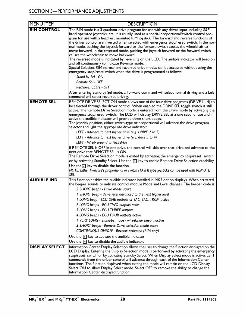
RIM CONTROL The RIM mode is a 3 quadrant drive program for use with any driver input including S&P, hand operated joysticks, etc. It is usually used as a special proportional/switch control pro-gram for use with a headrest mounted RIM joystick. The forward and reverse functions of the driver control are inverted when selected with emergency stop/reset switch. In the nor-mal mode, pushing the joystick forward or the forward switch causes the wheelchair to move forward. In the reversed mode, pushing the joystick forward or the forward switch causes the wheelchair to move backward.The reversed mode is indicated by reversing on the LCD. The audible indicator will beep on and off continuously to indicate Reverse mode. Special Solution: RIM normal and reversed drive modes can be accessed without using the emergency stop/reset switch when the drive is programmed as follows:
Stand-by Sel - ONRemote Sel - OFFRecliners, ECU's - OFF
After entering Stand-by Sel mode, a Forward command will select normal driving and a Left command will select reversed driving.
REMOTE SEL REMOTE DRIVE SELECTION mode allows one of the four drive programs (DRIVE 1 - 4) to be selected through the driver control. When enabled the DRIVE SEL toggle switch is still active. The Remote Drive Selection mode is entered from the Drive mode by activating the emergency stop/reset switch. The LCD will display DRIVE SEL at a one second rate and if active the audible indicator will provide three short beeps.The joystick position, either switch-type or proportional will advance the drive program selector and light the appropriate drive indicator:
LEFT - Advance to next higher drive (e.g. DRIVE 2 to 3)LEFT - Advance to next higher drive (e.g. drive 3 to 4)LEFT - Wrap around to First drive
If REMOTE SEL is OFF in one drive, the control will skip over that drive and advance to the next drive that REMOTE SEL is ON.The Remote Drive Selection mode is exited by activating the emergency stop/reset switch or by activating Standby Select. Use the key to enable Remote Drive Selection capability. Use the key to disable the function.NOTE: Either Invacare's proportional or switch (TASH) type joysticks can be used with REMOTE SEL.
AUDIBLE IND This function enables the audible indicator installed in MK5 option displays. When activated, the beeper sounds to indicate control module Mode and Level changes. The beeper code is:
2 SHORT beeps - Drive Mode active1 SHORT beep - Drive level advanced to the next higher level1 LONG beep - ECU ONE outputs or SAC, TAC, TRCM active 2 LONG beeps - ECU TWO outputs active3 LONG beeps - ECU THREE outputs 4 LONG beeps - ECU FOUR outputs active1 VERY LONG - Stand-by mode - wheelchair beep inactive3 SHORT beeps - Remote Drive, selection mode activeCONTINUOUS ON/OFF - Reverse activated (RIM only)
Use the key to activate the audible indicator.Use the key to disable the audible indicator.
DISPLAY SELECT Information Center Display Selection allows the user to change the function displayed on the LCD Display. Entering the Display Selection mode is performed by activating the emergency stop/reset switch or by activating Standby Select. When Display Select mode is active, LEFT commands from the driver control will advance through each of the Information Center functions. The function displayed when exiting the mode will remain on the LCD Display. Select ON to allow Display Select mode. Select OFF to remove the ability to change the Information Center displayed function.
MENU ITEM DESCRIPTION
MK5™EX™ and MK5
™TT-EX™ Electronics 28 Part No 1114808
SECTION 5—PERFORMANCE ADJUSTMENTS
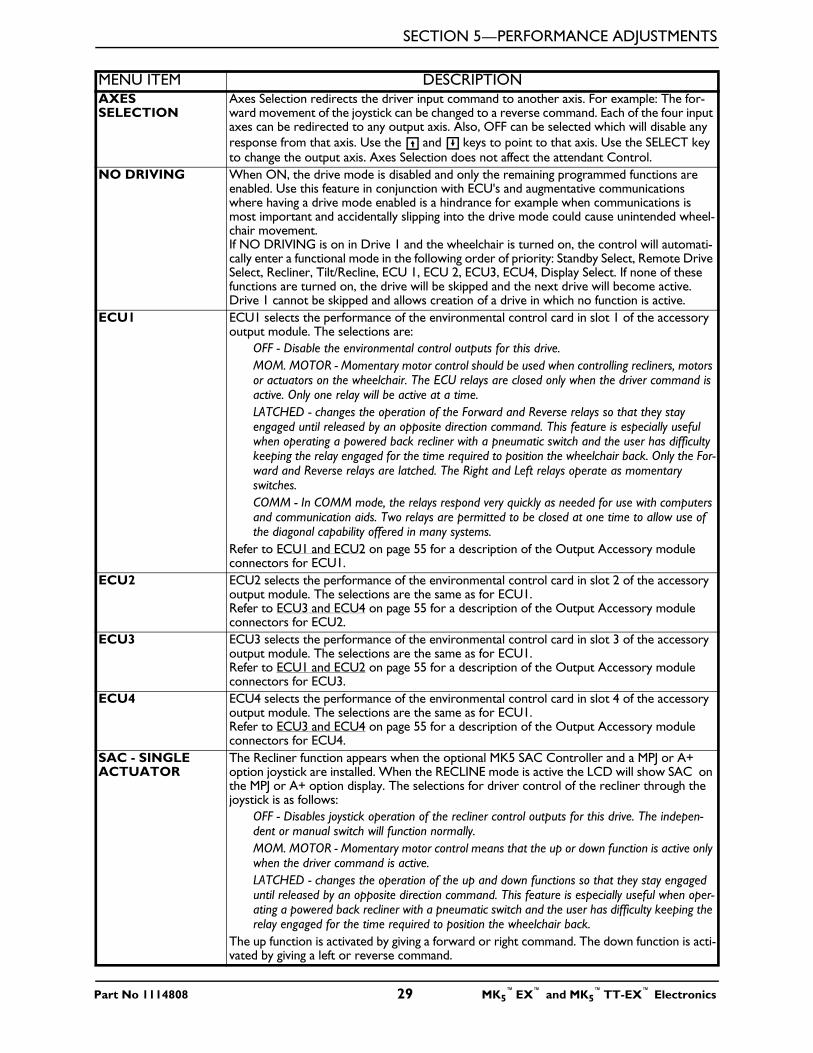
AXES SELECTION
Axes Selection redirects the driver input command to another axis. For example: The for-ward movement of the joystick can be changed to a reverse command. Each of the four input axes can be redirected to any output axis. Also, OFF can be selected which will disable any response from that axis. Use the and keys to point to that axis. Use the SELECT key to change the output axis. Axes Selection does not affect the attendant Control.
NO DRIVING When ON, the drive mode is disabled and only the remaining programmed functions are enabled. Use this feature in conjunction with ECU's and augmentative communications where having a drive mode enabled is a hindrance for example when communications is most important and accidentally slipping into the drive mode could cause unintended wheel-chair movement. If NO DRIVING is on in Drive 1 and the wheelchair is turned on, the control will automati-cally enter a functional mode in the following order of priority: Standby Select, Remote Drive Select, Recliner, Tilt/Recline, ECU 1, ECU 2, ECU3, ECU4, Display Select. If none of these functions are turned on, the drive will be skipped and the next drive will become active. Drive 1 cannot be skipped and allows creation of a drive in which no function is active.
ECU1 ECU1 selects the performance of the environmental control card in slot 1 of the accessory output module. The selections are:
OFF - Disable the environmental control outputs for this drive.MOM. MOTOR - Momentary motor control should be used when controlling recliners, motors or actuators on the wheelchair. The ECU relays are closed only when the driver command is active. Only one relay will be active at a time.LATCHED - changes the operation of the Forward and Reverse relays so that they stay engaged until released by an opposite direction command. This feature is especially useful when operating a powered back recliner with a pneumatic switch and the user has difficulty keeping the relay engaged for the time required to position the wheelchair back. Only the For-ward and Reverse relays are latched. The Right and Left relays operate as momentary switches.COMM - In COMM mode, the relays respond very quickly as needed for use with computers and communication aids. Two relays are permitted to be closed at one time to allow use of the diagonal capability offered in many systems.
Refer to ECU1 and ECU2 on page 55 for a description of the Output Accessory module connectors for ECU1.
ECU2 ECU2 selects the performance of the environmental control card in slot 2 of the accessory output module. The selections are the same as for ECU1.Refer to ECU3 and ECU4 on page 55 for a description of the Output Accessory module connectors for ECU2.
ECU3 ECU3 selects the performance of the environmental control card in slot 3 of the accessory output module. The selections are the same as for ECU1.Refer to ECU1 and ECU2 on page 55 for a description of the Output Accessory module connectors for ECU3.
ECU4 ECU4 selects the performance of the environmental control card in slot 4 of the accessory output module. The selections are the same as for ECU1.Refer to ECU3 and ECU4 on page 55 for a description of the Output Accessory module connectors for ECU4.
SAC - SINGLE ACTUATOR
The Recliner function appears when the optional MK5 SAC Controller and a MPJ or A+ option joystick are installed. When the RECLINE mode is active the LCD will show SAC on the MPJ or A+ option display. The selections for driver control of the recliner through the joystick is as follows:
OFF - Disables joystick operation of the recliner control outputs for this drive. The indepen-dent or manual switch will function normally.MOM. MOTOR - Momentary motor control means that the up or down function is active only when the driver command is active. LATCHED - changes the operation of the up and down functions so that they stay engaged until released by an opposite direction command. This feature is especially useful when oper-ating a powered back recliner with a pneumatic switch and the user has difficulty keeping the relay engaged for the time required to position the wheelchair back.
The up function is activated by giving a forward or right command. The down function is acti-vated by giving a left or reverse command.
MENU ITEM DESCRIPTION
Part No 1114808 29 MK5™EX™ and MK5
™TT-EX™ Electronics
SECTION 5—PERFORMANCE ADJUSTMENTS
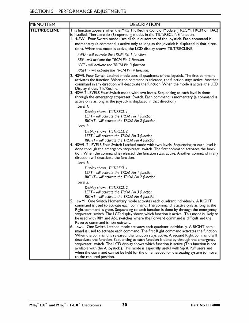
TILT/RECLINE This function appears when the MK5 Tilt Recline Control Module (TRECM, TRCM or TAC) is installed. There are six (6) operating modes in the TILT/RECLINE function. 1. 4-SW Four Switch mode uses all four quadrants of the joystick. Each command is
momentary (a command is active only as long as the joystick is displaced in that direc-tion). When the mode is active, the LCD display shows TILT/RECLINE.
FWD - will activate the TRCM Pin 1 function.REV - will activate the TRCM Pin 2 function.LEFT - will activate the TRCM Pin 3 function.RIGHT - will activate the TRCM Pin 4 function.
2. 4SWL Four Switch Latched mode uses all quadrants of the joystick. The first command activates the function. When the command is released, the function stays active. Another command in any direction will deactivate the function. When the mode is active, the LCD Display shows Tilt/Recline.
3. 4SW-2 LEVELS Four Switch mode with two levels. Sequencing to each level is done through the emergency stop/reset Switch. Each command is momentary (a command is active only as long as the joystick is displaced in that direction)
Level 1:Display shows TILT/RECL 1LEFT - will activate the TRCM Pin 1 functionRIGHT - will activate the TRCM Pin 2 function
Level 2:Display shows TILT/RECL 2LEFT - will activate the TRCM Pin 3 functionRIGHT - will activate the TRCM Pin 4 function
4. 4SWL-2 LEVELS Four Switch Latched mode with two levels. Sequencing to each level is done through the emergency stop/reset switch. The first command activates the func-tion. When the command is released, the function stays active. Another command in any direction will deactivate the function.
Level 1:Display shows TILT/RECL 1LEFT - will activate the TRCM Pin 1 functionRIGHT - will activate the TRCM Pin 2 function
Level 2:Display shows TILT/RECL 2LEFT - will activate the TRCM Pin 3 functionRIGHT - will activate the TRCM Pin 4 function
5. 1swM One Switch Momentary mode activates each quadrant individually. A RIGHT command is used to activate each command. The command is active only as long as the Right command is given. Sequencing to each function is done by through the emergency stop/reset switch. The LCD display shows which function is active. This mode is likely to be used with RIM and ASL switches where the Forward command is difficult and the Reverse command is non-existent.
6. 1swL One Switch Latched mode activates each quadrant individually. A RIGHT com-mand is used to activate each command. The first Right command activates the function. When the command is released, the function stays active. A second Right command will deactivate the function. Sequencing to each function is done by through the emergency stop/reset switch. The LCD display shows which function is active (This function is not available with the A joystick.). This mode is especially useful with Sip & Puff users and when the command cannot be held for the time needed for the seating system to move to the required position.
MENU ITEM DESCRIPTION
MK5™EX™ and MK5
™TT-EX™ Electronics 30 Part No 1114808
SECTION 5—PERFORMANCE ADJUSTMENTS
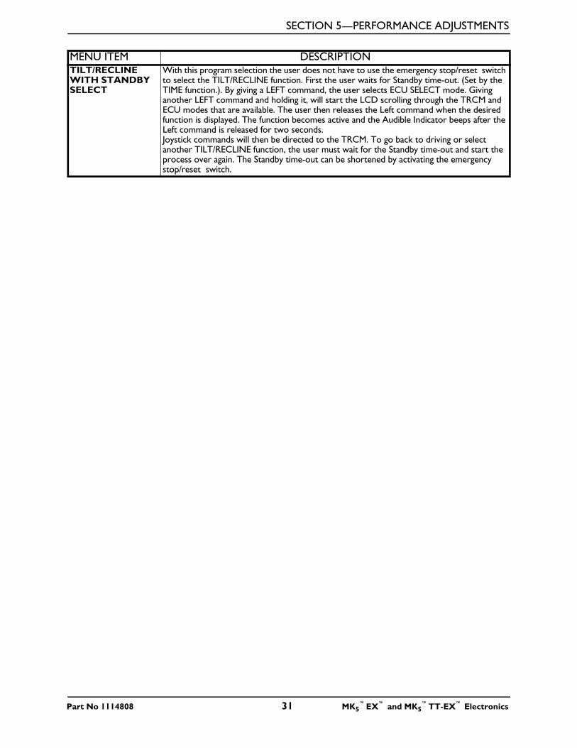
TILT/RECLINE WITH STANDBY SELECT
With this program selection the user does not have to use the emergency stop/reset switch to select the TILT/RECLINE function. First the user waits for Standby time-out. (Set by the TIME function.). By giving a LEFT command, the user selects ECU SELECT mode. Giving another LEFT command and holding it, will start the LCD scrolling through the TRCM and ECU modes that are available. The user then releases the Left command when the desired function is displayed. The function becomes active and the Audible Indicator beeps after the Left command is released for two seconds.Joystick commands will then be directed to the TRCM. To go back to driving or select another TILT/RECLINE function, the user must wait for the Standby time-out and start the process over again. The Standby time-out can be shortened by activating the emergency stop/reset switch.
MENU ITEM DESCRIPTION
Part No 1114808 31 MK5™EX™ and MK5
™TT-EX™ Electronics
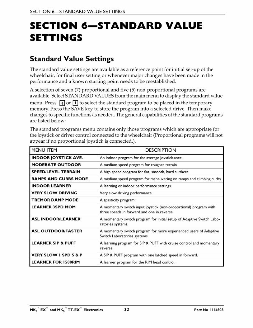
SECTION 6—STANDARD VALUE SETTINGS
MK5™EX™ and MK5
™TT-EX™ Electronics 32 Part No 1114808
SECTION 6—STANDARD VALUE SETTINGS
Standard Value SettingsThe standard value settings are available as a reference point for initial set-up of the wheelchair, for final user setting or whenever major changes have been made in the performance and a known starting point needs to be reestablished.
A selection of seven (7) proportional and five (5) non-proportional programs are available. Select STANDARD VALUES from the main menu to display the standard value menu. Press or to select the standard program to be placed in the temporary memory. Press the SAVE key to store the program into a selected drive. Then make changes to specific functions as needed. The general capabilities of the standard programs are listed below:
The standard programs menu contains only those programs which are appropriate for the joystick or driver control connected to the wheelchair (Proportional programs will not appear if no proportional joystick is connected.).
MENU ITEM DESCRIPTIONINDOOR JOYSTICK AVE. An indoor program for the average joystick user.
MODERATE OUTDOOR A medium speed program for rougher terrain.
SPEED/LEVEL TERRAIN A high speed program for flat, smooth, hard surfaces.
RAMPS AND CURBS MODE A medium speed program for maneuvering on ramps and climbing curbs.
INDOOR LEARNER A learning or indoor performance settings.
VERY SLOW DRIVING Very slow driving performance.
TREMOR DAMP MODE A spasticity program.
LEARNER 3SPD MOM A momentary switch input joystick (non-proportional) program with three speeds in forward and one in reverse.
ASL INDOOR/LEARNER A momentary switch program for initial setup of Adaptive Switch Labo-ratories systems.
ASL OUTDOOR/FASTER A momentary switch program for more experienced users of Adaptive Switch Laboratories systems.
LEARNER SIP & PUFF A learning program for SIP & PUFF with cruise control and momentary reverse.
VERY SLOW 1 SPD S & P A SIP & PUFF program with one latched speed in forward.
LEARNER FOR 1500RIM A learner program for the RIM head control.
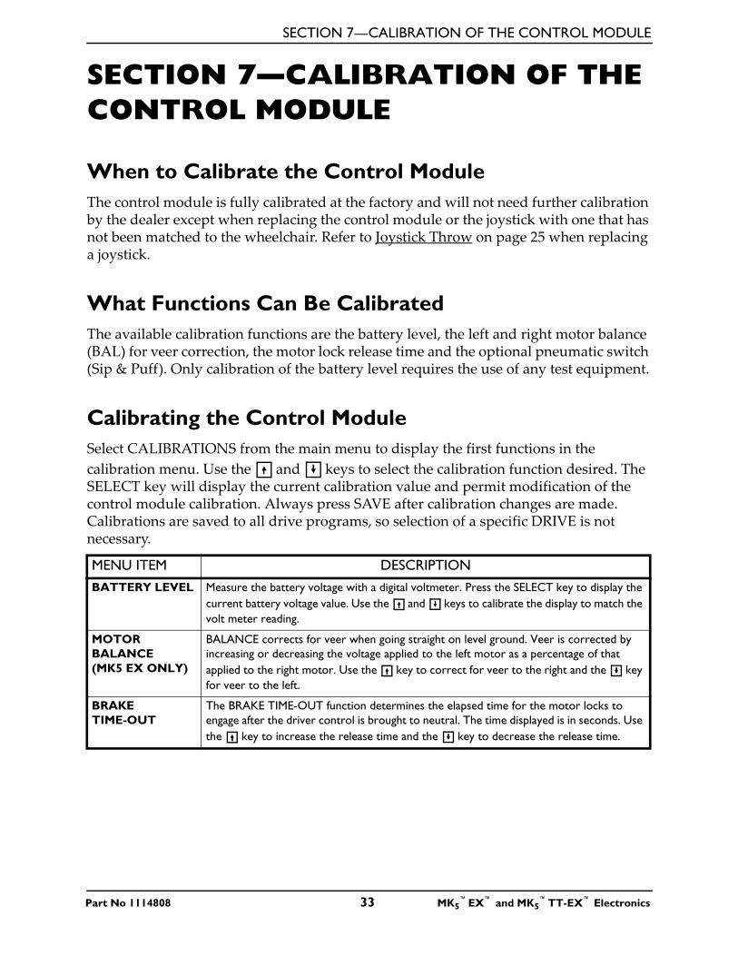
SECTION 7—CALIBRATION OF THE CONTROL MODULE
SECTION 7—CALIBRATION OF THE CONTROL MODULE
When to Calibrate the Control ModuleThe control module is fully calibrated at the factory and will not need further calibration by the dealer except when replacing the control module or the joystick with one that has not been matched to the wheelchair. Refer to Joystick Throw on page 25 when replacing a joystick.
What Functions Can Be CalibratedThe available calibration functions are the battery level, the left and right motor balance (BAL) for veer correction, the motor lock release time and the optional pneumatic switch (Sip & Puff). Only calibration of the battery level requires the use of any test equipment.
Calibrating the Control ModuleSelect CALIBRATIONS from the main menu to display the first functions in the calibration menu. Use the and keys to select the calibration function desired. The SELECT key will display the current calibration value and permit modification of the control module calibration. Always press SAVE after calibration changes are made. Calibrations are saved to all drive programs, so selection of a specific DRIVE is not necessary.
MENU ITEM DESCRIPTIONBATTERY LEVEL Measure the battery voltage with a digital voltmeter. Press the SELECT key to display the
current battery voltage value. Use the and keys to calibrate the display to match the volt meter reading.
MOTOR BALANCE (MK5 EX ONLY)
BALANCE corrects for veer when going straight on level ground. Veer is corrected by increasing or decreasing the voltage applied to the left motor as a percentage of that applied to the right motor. Use the key to correct for veer to the right and the key for veer to the left.
BRAKE TIME-OUT
The BRAKE TIME-OUT function determines the elapsed time for the motor locks to engage after the driver control is brought to neutral. The time displayed is in seconds. Use the key to increase the release time and the key to decrease the release time.
Part No 1114808 33 MK5™EX™ and MK5
™TT-EX™ Electronics
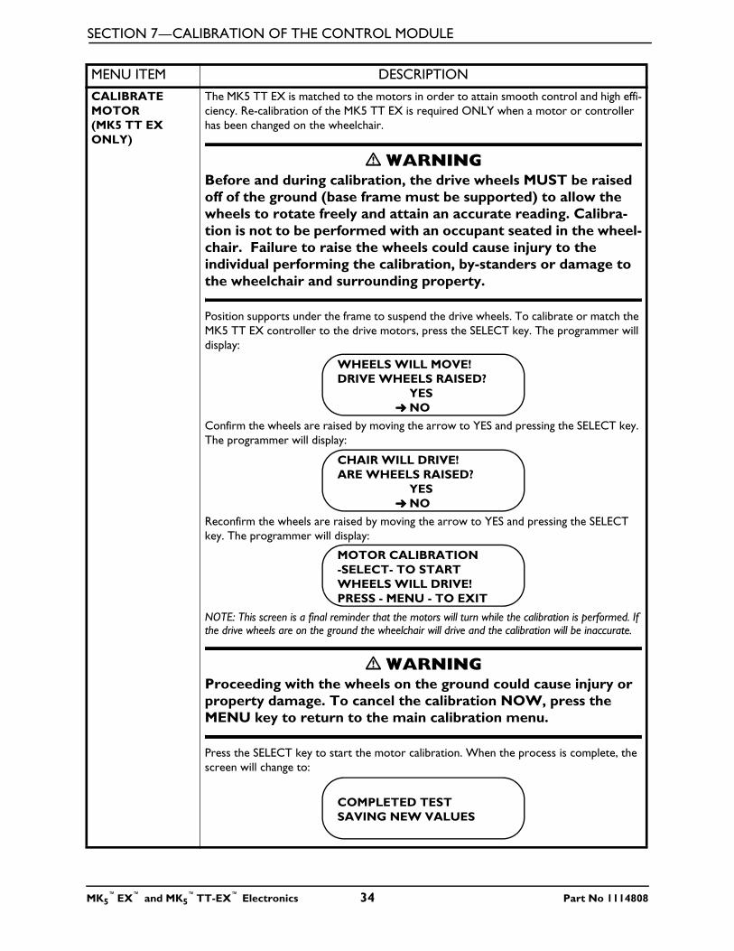
SECTION 7—CALIBRATION OF THE CONTROL MODULE
CALIBRATE MOTOR (MK5 TT EX ONLY)
The MK5 TT EX is matched to the motors in order to attain smooth control and high effi-ciency. Re-calibration of the MK5 TT EX is required ONLY when a motor or controller has been changed on the wheelchair.
� WARNINGBefore and during calibration, the drive wheels MUST be raised off of the ground (base frame must be supported) to allow the wheels to rotate freely and attain an accurate reading. Calibra-tion is not to be performed with an occupant seated in the wheel-chair. Failure to raise the wheels could cause injury to the individual performing the calibration, by-standers or damage to the wheelchair and surrounding property.
Position supports under the frame to suspend the drive wheels. To calibrate or match the MK5 TT EX controller to the drive motors, press the SELECT key. The programmer will display:
Confirm the wheels are raised by moving the arrow to YES and pressing the SELECT key. The programmer will display:
Reconfirm the wheels are raised by moving the arrow to YES and pressing the SELECT key. The programmer will display:
NOTE: This screen is a final reminder that the motors will turn while the calibration is performed. If the drive wheels are on the ground the wheelchair will drive and the calibration will be inaccurate.
� WARNINGProceeding with the wheels on the ground could cause injury or property damage. To cancel the calibration NOW, press the MENU key to return to the main calibration menu.
Press the SELECT key to start the motor calibration. When the process is complete, the screen will change to:
MENU ITEM DESCRIPTION
WHEELS WILL MOVE!DRIVE WHEELS RAISED?
YES➜ NO
CHAIR WILL DRIVE!ARE WHEELS RAISED?
YES➜ NO
MOTOR CALIBRATION-SELECT- TO STARTWHEELS WILL DRIVE!PRESS - MENU - TO EXIT
COMPLETED TESTSAVING NEW VALUES
MK5™EX™ and MK5
™TT-EX™ Electronics 34 Part No 1114808
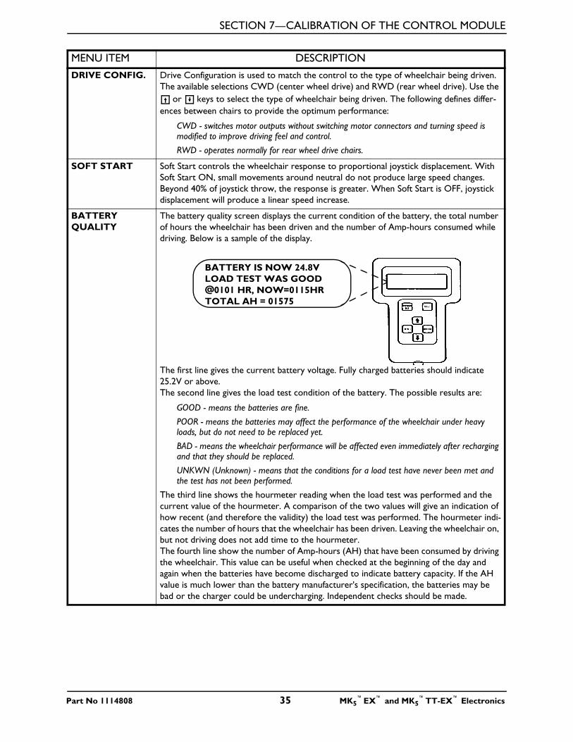
SECTION 7—CALIBRATION OF THE CONTROL MODULE
DRIVE CONFIG. Drive Configuration is used to match the control to the type of wheelchair being driven. The available selections CWD (center wheel drive) and RWD (rear wheel drive). Use the
or keys to select the type of wheelchair being driven. The following defines differ-ences between chairs to provide the optimum performance:
CWD - switches motor outputs without switching motor connectors and turning speed is modified to improve driving feel and control.
RWD - operates normally for rear wheel drive chairs.
SOFT START Soft Start controls the wheelchair response to proportional joystick displacement. With Soft Start ON, small movements around neutral do not produce large speed changes. Beyond 40% of joystick throw, the response is greater. When Soft Start is OFF, joystick displacement will produce a linear speed increase.
BATTERY QUALITY
The battery quality screen displays the current condition of the battery, the total number of hours the wheelchair has been driven and the number of Amp-hours consumed while driving. Below is a sample of the display.
The first line gives the current battery voltage. Fully charged batteries should indicate 25.2V or above. The second line gives the load test condition of the battery. The possible results are:
GOOD - means the batteries are fine.
POOR - means the batteries may affect the performance of the wheelchair under heavy loads, but do not need to be replaced yet.
BAD - means the wheelchair performance will be affected even immediately after recharging and that they should be replaced.
UNKWN (Unknown) - means that the conditions for a load test have never been met and the test has not been performed.
The third line shows the hourmeter reading when the load test was performed and the current value of the hourmeter. A comparison of the two values will give an indication of how recent (and therefore the validity) the load test was performed. The hourmeter indi-cates the number of hours that the wheelchair has been driven. Leaving the wheelchair on, but not driving does not add time to the hourmeter. The fourth line show the number of Amp-hours (AH) that have been consumed by driving the wheelchair. This value can be useful when checked at the beginning of the day and again when the batteries have become discharged to indicate battery capacity. If the AH value is much lower than the battery manufacturer's specification, the batteries may be bad or the charger could be undercharging. Independent checks should be made.
MENU ITEM DESCRIPTION
BATTERY IS NOW 24.8VLOAD TEST WAS GOOD@0101 HR, NOW=0115HRTOTAL AH = 01575
Part No 1114808 35 MK5™EX™ and MK5
™TT-EX™ Electronics
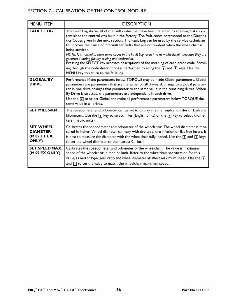
SECTION 7—CALIBRATION OF THE CONTROL MODULE
FAULT LOG The Fault Log shows all of the fault codes that have been detected by the diagnostic sys-tem since the control was built in the factory. The fault codes correspond to the Diagnos-tics Codes given in the next section. The Fault Log can be used by the service technician to uncover the cause of intermittent faults that are not evident when the wheelchair is being serviced. NOTE: It is normal to have some codes in the Fault Log, even in a new wheelchair, because they are generated during factory testing and calibration.Pressing the SELECT key accesses descriptions of the meaning of each error code. Scroll-ing through the code descriptions is performed by using the and keys. Use the MENU key to return to the fault log.
GLOBAL/BY DRIVE
Performance Menu parameters below TORQUE may be made Global parameters. Global parameters are parameters that are the same for all drives. A change to a global parame-ter in one drive changes that parameter to the same value in the remaining drives. When By Drive is selected, the parameters are independent in each drive.Use the to select Global and make all performance parameters below TORQUE the same value in all drives.
SET MILES/KM The speedometer and odometer can be set to display in either mph and miles or kmh and kilometers. Use the key to select miles (English units) or the key to select kilome-ters (metric units).
SET WHEEL DIAMETER (MK5 TT EX ONLY)
Calibrates the speedometer and odometer of the wheelchair. The wheel diameter is mea-sured in inches. Wheel diameter can vary with tire type, tire inflation or flat free insert. It is best to measure the diameter with the wheelchair fully loaded. Use the and keys to set the wheel diameter to the nearest 0.1 inch.
SET SPEED MAX. (MK5 EX ONLY)
Calibrates the speedometer and odometer of the wheelchair. The value is maximum speed of the wheelchair in mph or kmh. Refer to the wheelchair specification for this value, as motor type, gear ratio and wheel diameter all affect maximum speed. Use the and to set the value to match the wheelchair maximum speed.
MENU ITEM DESCRIPTION
MK5™EX™ and MK5
™TT-EX™ Electronics 36 Part No 1114808
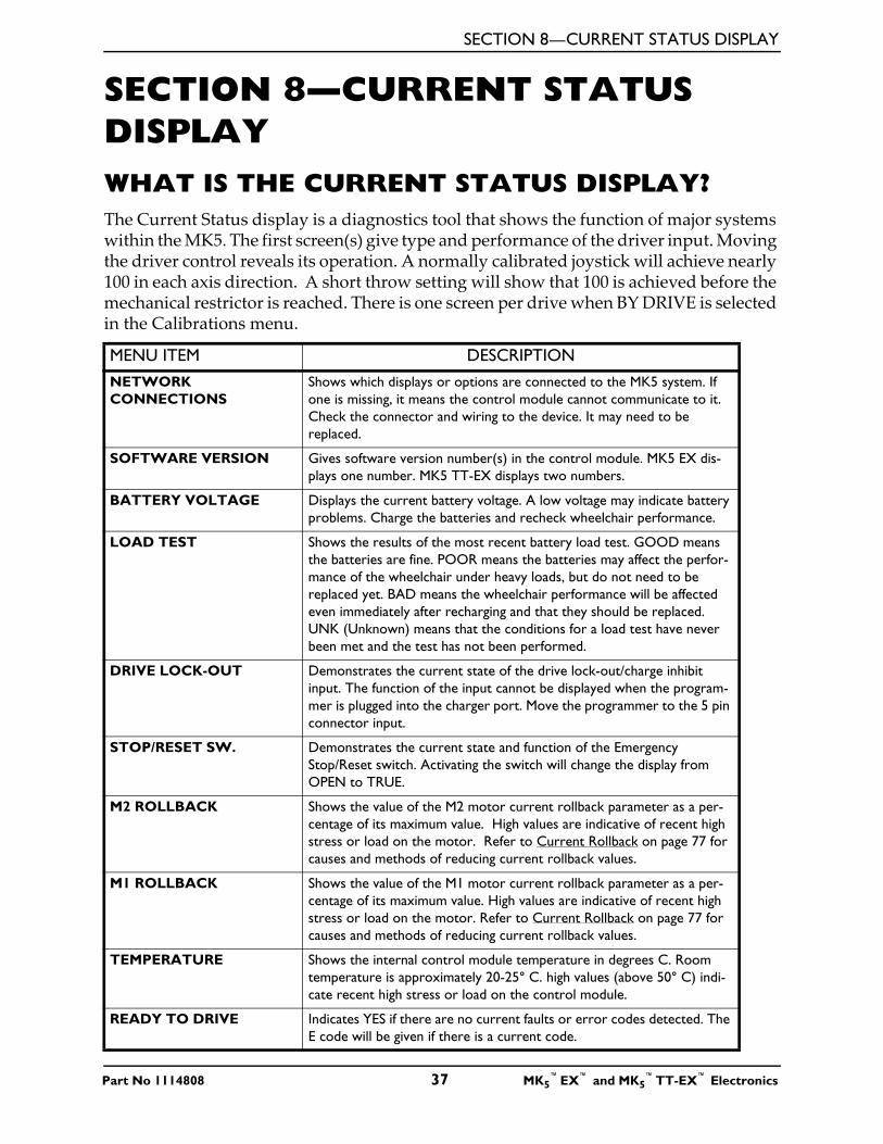
SECTION 8—CURRENT STATUS DISPLAY
Part No 1114808 37 MK5™EX™ and MK5
™TT-EX™ Electronics
SECTION 8—CURRENT STATUS DISPLAYWHAT IS THE CURRENT STATUS DISPLAY?The Current Status display is a diagnostics tool that shows the function of major systems within the MK5. The first screen(s) give type and performance of the driver input. Moving the driver control reveals its operation. A normally calibrated joystick will achieve nearly 100 in each axis direction. A short throw setting will show that 100 is achieved before the mechanical restrictor is reached. There is one screen per drive when BY DRIVE is selected in the Calibrations menu.
MENU ITEM DESCRIPTIONNETWORK CONNECTIONS
Shows which displays or options are connected to the MK5 system. If one is missing, it means the control module cannot communicate to it. Check the connector and wiring to the device. It may need to be replaced.
SOFTWARE VERSION Gives software version number(s) in the control module. MK5 EX dis-plays one number. MK5 TT-EX displays two numbers.
BATTERY VOLTAGE Displays the current battery voltage. A low voltage may indicate battery problems. Charge the batteries and recheck wheelchair performance.
LOAD TEST Shows the results of the most recent battery load test. GOOD means the batteries are fine. POOR means the batteries may affect the perfor-mance of the wheelchair under heavy loads, but do not need to be replaced yet. BAD means the wheelchair performance will be affected even immediately after recharging and that they should be replaced. UNK (Unknown) means that the conditions for a load test have never been met and the test has not been performed.
DRIVE LOCK-OUT Demonstrates the current state of the drive lock-out/charge inhibit input. The function of the input cannot be displayed when the program-mer is plugged into the charger port. Move the programmer to the 5 pin connector input.
STOP/RESET SW. Demonstrates the current state and function of the Emergency Stop/Reset switch. Activating the switch will change the display from OPEN to TRUE.
M2 ROLLBACK Shows the value of the M2 motor current rollback parameter as a per-centage of its maximum value. High values are indicative of recent high stress or load on the motor. Refer to Current Rollback on page 77 for causes and methods of reducing current rollback values.
M1 ROLLBACK Shows the value of the M1 motor current rollback parameter as a per-centage of its maximum value. High values are indicative of recent high stress or load on the motor. Refer to Current Rollback on page 77 for causes and methods of reducing current rollback values.
TEMPERATURE Shows the internal control module temperature in degrees C. Room temperature is approximately 20-25° C. high values (above 50° C) indi-cate recent high stress or load on the control module.
READY TO DRIVE Indicates YES if there are no current faults or error codes detected. The E code will be given if there is a current code.
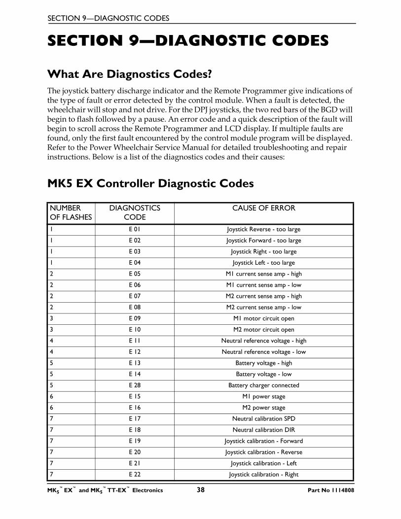
SECTION 9—DIAGNOSTIC CODES
SECTION 9—DIAGNOSTIC CODES
What Are Diagnostics Codes?The joystick battery discharge indicator and the Remote Programmer give indications of the type of fault or error detected by the control module. When a fault is detected, the wheelchair will stop and not drive. For the DPJ joysticks, the two red bars of the BGD will begin to flash followed by a pause. An error code and a quick description of the fault will begin to scroll across the Remote Programmer and LCD display. If multiple faults are found, only the first fault encountered by the control module program will be displayed. Refer to the Power Wheelchair Service Manual for detailed troubleshooting and repair instructions. Below is a list of the diagnostics codes and their causes:
MK5 EX Controller Diagnostic Codes
NUMBER OF FLASHES
DIAGNOSTICS CODE
CAUSE OF ERROR
1 E 01 Joystick Reverse - too large
1 E 02 Joystick Forward - too large
1 E 03 Joystick Right - too large
1 E 04 Joystick Left - too large
2 E 05 M1 current sense amp - high
2 E 06 M1 current sense amp - low
2 E 07 M2 current sense amp - high
2 E 08 M2 current sense amp - low
3 E 09 M1 motor circuit open
3 E 10 M2 motor circuit open
4 E 11 Neutral reference voltage - high
4 E 12 Neutral reference voltage - low
5 E 13 Battery voltage - high
5 E 14 Battery voltage - low
5 E 28 Battery charger connected
6 E 15 M1 power stage
6 E 16 M2 power stage
7 E 17 Neutral calibration SPD
7 E 18 Neutral calibration DIR
7 E 19 Joystick calibration - Forward
7 E 20 Joystick calibration - Reverse
7 E 21 Joystick calibration - Left
7 E 22 Joystick calibration - Right
MK5™EX™ and MK5
™TT-EX™ Electronics 38 Part No 1114808
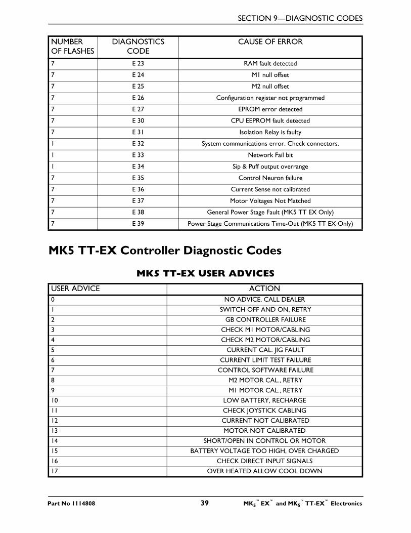
SECTION 9—DIAGNOSTIC CODES
MK5 TT-EX Controller Diagnostic Codes
7 E 23 RAM fault detected
7 E 24 M1 null offset
7 E 25 M2 null offset
7 E 26 Configuration register not programmed
7 E 27 EPROM error detected
7 E 30 CPU EEPROM fault detected
7 E 31 Isolation Relay is faulty
1 E 32 System communications error. Check connectors.
1 E 33 Network Fail bit
1 E 34 Sip & Puff output overrange
7 E 35 Control Neuron failure
7 E 36 Current Sense not calibrated
7 E 37 Motor Voltages Not Matched
7 E 38 General Power Stage Fault (MK5 TT EX Only)
7 E 39 Power Stage Communications Time-Out (MK5 TT EX Only)
MK5 TT-EX USER ADVICESUSER ADVICE ACTION0 NO ADVICE, CALL DEALER
1 SWITCH OFF AND ON, RETRY
2 GB CONTROLLER FAILURE
3 CHECK M1 MOTOR/CABLING
4 CHECK M2 MOTOR/CABLING
5 CURRENT CAL. JIG FAULT
6 CURRENT LIMIT TEST FAILURE
7 CONTROL SOFTWARE FAILURE
8 M2 MOTOR CAL., RETRY
9 M1 MOTOR CAL., RETRY
10 LOW BATTERY, RECHARGE
11 CHECK JOYSTICK CABLING
12 CURRENT NOT CALIBRATED
13 MOTOR NOT CALIBRATED
14 SHORT/OPEN IN CONTROL OR MOTOR
15 BATTERY VOLTAGE TOO HIGH, OVER CHARGED
16 CHECK DIRECT INPUT SIGNALS
17 OVER HEATED ALLOW COOL DOWN
NUMBER OF FLASHES
DIAGNOSTICS CODE
CAUSE OF ERROR
Part No 1114808 39 MK5™EX™ and MK5
™TT-EX™ Electronics
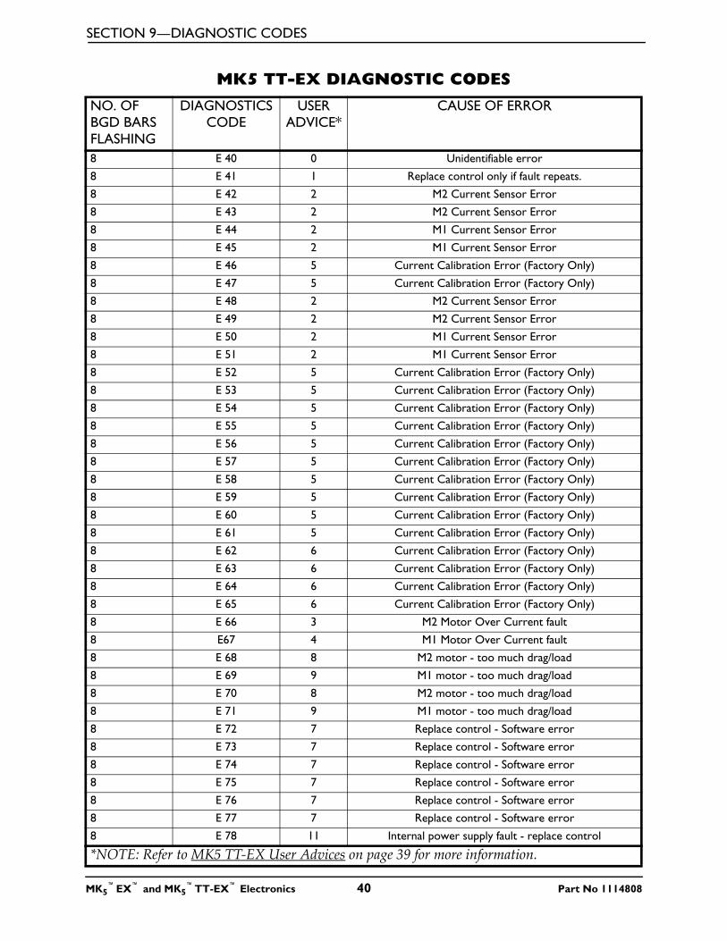
SECTION 9—DIAGNOSTIC CODES
MK5 TT-EX DIAGNOSTIC CODESNO. OF BGD BARS FLASHING
DIAGNOSTICS CODE
USER ADVICE*
CAUSE OF ERROR
8 E 40 0 Unidentifiable error
8 E 41 1 Replace control only if fault repeats.
8 E 42 2 M2 Current Sensor Error
8 E 43 2 M2 Current Sensor Error
8 E 44 2 M1 Current Sensor Error
8 E 45 2 M1 Current Sensor Error
8 E 46 5 Current Calibration Error (Factory Only)
8 E 47 5 Current Calibration Error (Factory Only)
8 E 48 2 M2 Current Sensor Error
8 E 49 2 M2 Current Sensor Error
8 E 50 2 M1 Current Sensor Error
8 E 51 2 M1 Current Sensor Error
8 E 52 5 Current Calibration Error (Factory Only)
8 E 53 5 Current Calibration Error (Factory Only)
8 E 54 5 Current Calibration Error (Factory Only)
8 E 55 5 Current Calibration Error (Factory Only)
8 E 56 5 Current Calibration Error (Factory Only)
8 E 57 5 Current Calibration Error (Factory Only)
8 E 58 5 Current Calibration Error (Factory Only)
8 E 59 5 Current Calibration Error (Factory Only)
8 E 60 5 Current Calibration Error (Factory Only)
8 E 61 5 Current Calibration Error (Factory Only)
8 E 62 6 Current Calibration Error (Factory Only)
8 E 63 6 Current Calibration Error (Factory Only)
8 E 64 6 Current Calibration Error (Factory Only)
8 E 65 6 Current Calibration Error (Factory Only)
8 E 66 3 M2 Motor Over Current fault
8 E67 4 M1 Motor Over Current fault
8 E 68 8 M2 motor - too much drag/load
8 E 69 9 M1 motor - too much drag/load
8 E 70 8 M2 motor - too much drag/load
8 E 71 9 M1 motor - too much drag/load
8 E 72 7 Replace control - Software error
8 E 73 7 Replace control - Software error
8 E 74 7 Replace control - Software error
8 E 75 7 Replace control - Software error
8 E 76 7 Replace control - Software error
8 E 77 7 Replace control - Software error
8 E 78 11 Internal power supply fault - replace control
*NOTE: Refer to MK5 TT-EX User Advices on page 39 for more information.
MK5™EX™ and MK5
™TT-EX™ Electronics 40 Part No 1114808
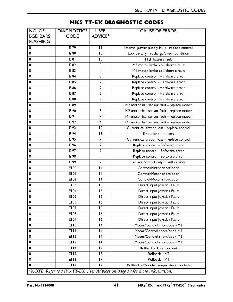
SECTION 9—DIAGNOSTIC CODES
8 E 79 11 Internal power supply fault - replace control
8 E 80 10 Low battery - recharge/check condition
8 E 81 15 High battery fault
8 E 82 3 M2 motor brake coil short circuit
8 E 83 4 M1 motor brake coil short circuit
8 E 84 2 Replace control - Hardware error
8 E 85 2 Replace control - Hardware error
8 E 86 2 Replace control - Hardware error
8 E 87 2 Replace control - Hardware error
8 E 88 2 Replace control - Hardware error
8 E 89 3 M2 motor hall sensor fault - replace motor
8 E 90 3 M2 motor hall sensor fault - replace motor
8 E 91 4 M1 motor hall sensor fault - replace motor
8 E 92 4 M1 motor hall sensor fault - replace motor
8 E 93 12 Current calibration lost - replace control
8 E 94 13 Re-calibrate motors
8 E 95 7 Current calibration lost - replace control
8 E 96 2 Replace control - Software error
8 E 97 2 Replace control - Software error
8 E 98 - Replace control - Software error
8 E 99 2 Replace control only if fault repeats.
8 E100 14 Control/Motor short/open
8 E101 14 Control/Motor short/open
8 E102 14 Control/Motor short/open
8 E103 16 Direct Input Joystick Fault
8 E104 16 Direct Input Joystick Fault
8 E105 16 Direct Input Joystick Fault
8 E106 16 Direct Input Joystick Fault
8 E107 16 Direct Input Joystick Fault
8 E108 16 Direct Input Joystick Fault
8 E109 16 Direct Input Joystick Fault
8 E110 14 Motor/Control short/open-M2
8 E111 14 Motor/Control short/open-M1
8 E112 14 Motor/Control short/open-M2
8 E113 14 Motor/Control short/open-M1
8 E114 17 Rollback - Total current
8 E115 17 Rollback - M2
8 E116 17 Rollback - M1
8 E117 17 Rollback - Module Temperature too high
MK5 TT-EX DIAGNOSTIC CODESNO. OF BGD BARS FLASHING
DIAGNOSTICS CODE
USER ADVICE*
CAUSE OF ERROR
*NOTE: Refer to MK5 TT-EX User Advices on page 39 for more information.
Part No 1114808 41 MK5™EX™ and MK5
™TT-EX™ Electronics
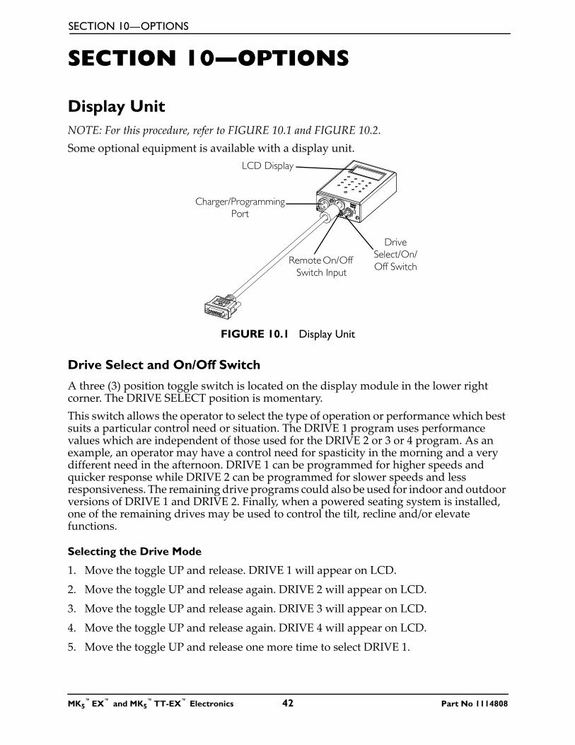
SECTION 10—OPTIONS
SECTION 10—OPTIONS
Display UnitNOTE: For this procedure, refer to FIGURE 10.1 and FIGURE 10.2.Some optional equipment is available with a display unit.
FIGURE 10.1 Display Unit
Drive Select and On/Off Switch
A three (3) position toggle switch is located on the display module in the lower right corner. The DRIVE SELECT position is momentary.This switch allows the operator to select the type of operation or performance which best suits a particular control need or situation. The DRIVE 1 program uses performance values which are independent of those used for the DRIVE 2 or 3 or 4 program. As an example, an operator may have a control need for spasticity in the morning and a very different need in the afternoon. DRIVE 1 can be programmed for higher speeds and quicker response while DRIVE 2 can be programmed for slower speeds and less responsiveness. The remaining drive programs could also be used for indoor and outdoor versions of DRIVE 1 and DRIVE 2. Finally, when a powered seating system is installed, one of the remaining drives may be used to control the tilt, recline and/or elevate functions.
Selecting the Drive Mode
1. Move the toggle UP and release. DRIVE 1 will appear on LCD.
2. Move the toggle UP and release again. DRIVE 2 will appear on LCD.
3. Move the toggle UP and release again. DRIVE 3 will appear on LCD.
4. Move the toggle UP and release again. DRIVE 4 will appear on LCD.
5. Move the toggle UP and release one more time to select DRIVE 1.
Drive Select/On/Off Switch
LCD Display
Charger/Programming Port
Remote On/Off Switch Input
MK5™EX™ and MK5
™TT-EX™ Electronics 42 Part No 1114808
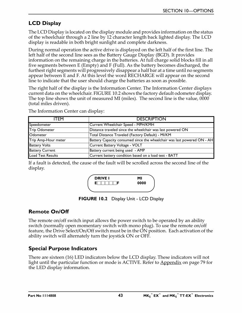
SECTION 10—OPTIONS
LCD Display
The LCD Display is located on the display module and provides information on the status of the wheelchair through a 2 line by 12 character length back lighted display. The LCD display is readable in both bright sunlight and complete darkness.During normal operation the active drive is displayed on the left half of the first line. The left half of the second line sees as the Battery Gauge Display (BGD). It provides information on the remaining charge in the batteries. At full charge solid blocks fill in all five segments between E (Empty) and F (Full). As the battery becomes discharged, the furthest right segments will progressively disappear a half bar at a time until no segments appear between E and F. At this level the word RECHARGE will appear on the second line to indicate that the user should charge the batteries as soon as possible.The right half of the display is the Information Center. The Information Center displays current data on the wheelchair. FIGURE 10.2 shows the factory default odometer display. The top line shows the unit of measured MI (miles). The second line is the value, 0000 (total miles driven).The Information Center can display:
If a fault is detected, the cause of the fault will be scrolled across the second line of the display.
FIGURE 10.2 Display Unit - LCD Display
Remote On/Off
The remote on/off switch input allows the power switch to be operated by an ability switch (normally open momentary switch with mono plug). To use the remote on/off feature, the Drive Select/On/Off switch must be in the ON position. Each activation of the ability switch will alternately turn the joystick ON or OFF.
Special Purpose Indicators
There are sixteen (16) LED indicators below the LCD display. These indicators will not light until the particular function or mode is ACTIVE. Refer to Appendix on page 79 for the LED display information.
ITEM DESCRIPTIONSpeedometer Current Wheelchair Speed - MPH/KMHTrip Odometer Distance traveled since the wheelchair was last powered ONOdometer Total Distance Traveled (Factory Default) - MI/KMTrip Amp-Hour meter Battery Capacity consumed since the wheelchair was last powered ON - AHBattery Volts Current Battery Voltage - VOLTBattery Current Battery current being used - AMPLoad Test Results Current battery condition based on a load test - BATT
DRIVE I MIE�����F 0000
Part No 1114808 43 MK5™EX™ and MK5
™TT-EX™ Electronics
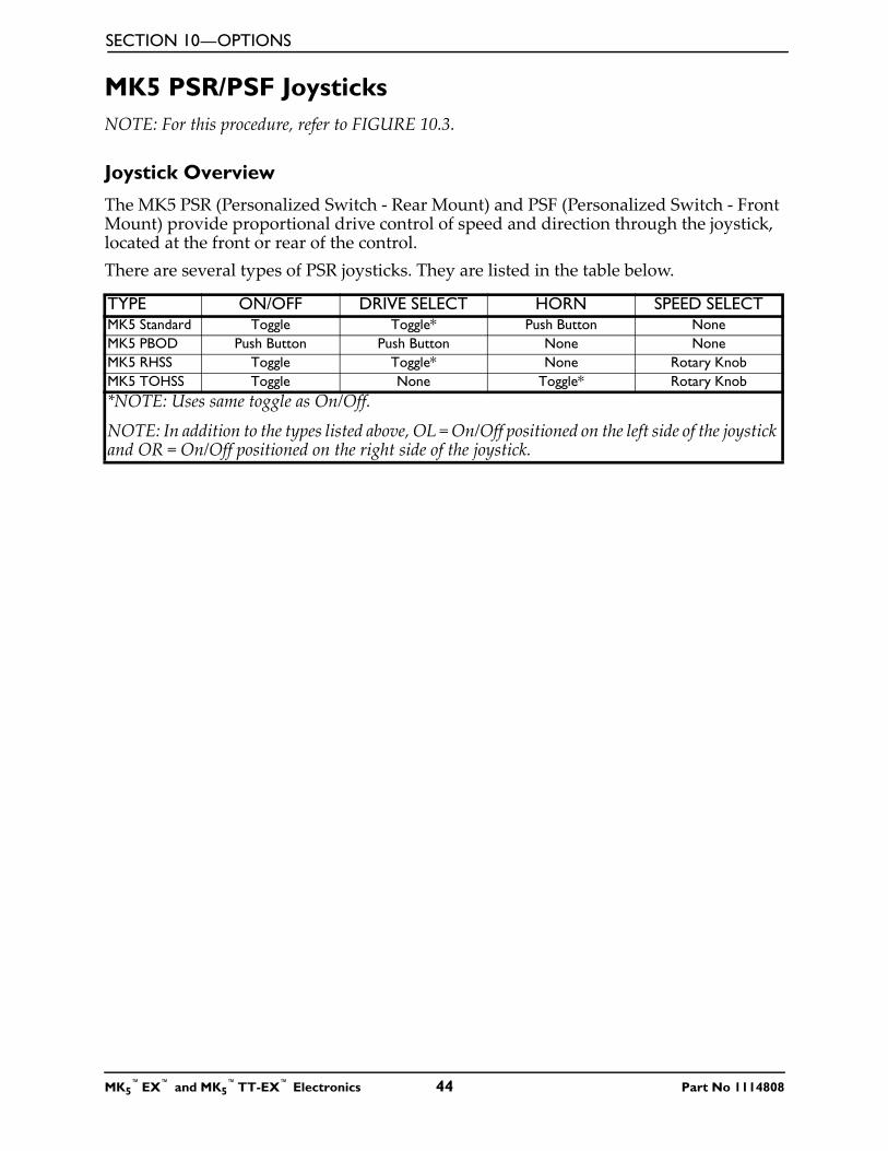
SECTION 10—OPTIONS
MK5 PSR/PSF JoysticksNOTE: For this procedure, refer to FIGURE 10.3.
Joystick Overview
The MK5 PSR (Personalized Switch - Rear Mount) and PSF (Personalized Switch - Front Mount) provide proportional drive control of speed and direction through the joystick, located at the front or rear of the control.There are several types of PSR joysticks. They are listed in the table below.
TYPE ON/OFF DRIVE SELECT HORN SPEED SELECTMK5 Standard Toggle Toggle* Push Button NoneMK5 PBOD Push Button Push Button None NoneMK5 RHSS Toggle Toggle* None Rotary KnobMK5 TOHSS Toggle None Toggle* Rotary Knob*NOTE: Uses same toggle as On/Off.
NOTE: In addition to the types listed above, OL = On/Off positioned on the left side of the joystick and OR = On/Off positioned on the right side of the joystick.
MK5™EX™ and MK5
™TT-EX™ Electronics 44 Part No 1114808
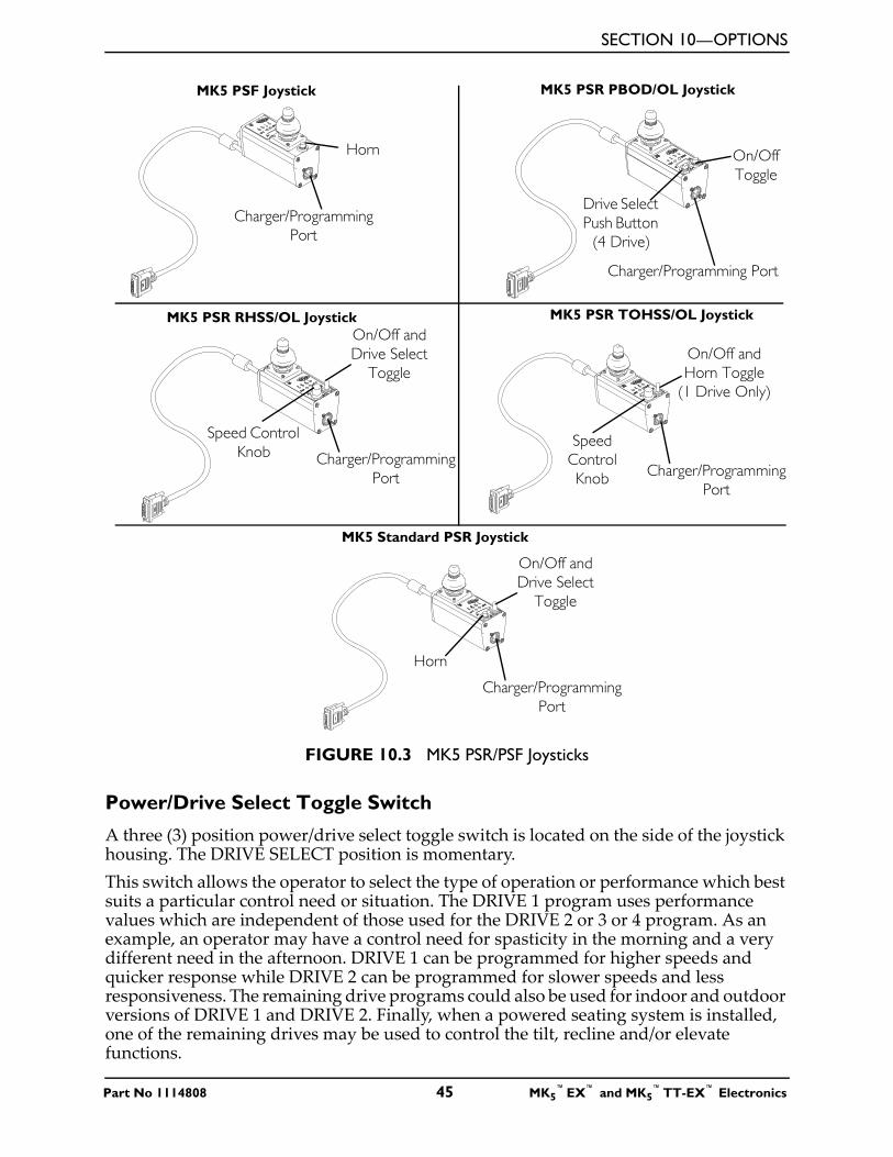
SECTION 10—OPTIONS
FIGURE 10.3 MK5 PSR/PSF Joysticks
Power/Drive Select Toggle Switch
A three (3) position power/drive select toggle switch is located on the side of the joystick housing. The DRIVE SELECT position is momentary.This switch allows the operator to select the type of operation or performance which best suits a particular control need or situation. The DRIVE 1 program uses performance values which are independent of those used for the DRIVE 2 or 3 or 4 program. As an example, an operator may have a control need for spasticity in the morning and a very different need in the afternoon. DRIVE 1 can be programmed for higher speeds and quicker response while DRIVE 2 can be programmed for slower speeds and less responsiveness. The remaining drive programs could also be used for indoor and outdoor versions of DRIVE 1 and DRIVE 2. Finally, when a powered seating system is installed, one of the remaining drives may be used to control the tilt, recline and/or elevate functions.
MK5 PSF Joystick
Charger/Programming Port
Horn
MK5 PSR PBOD/OL Joystick
Charger/Programming Port
On/Off Toggle
MK5 PSR RHSS/OL Joystick
Charger/Programming Port
On/Off and Drive Select
Toggle
Drive Select Push Button
(4 Drive)
Speed Control Knob
MK5 PSR TOHSS/OL Joystick
Charger/Programming Port
On/Off and Horn Toggle
(1 Drive Only)
Speed Control Knob
MK5 Standard PSR Joystick
Charger/Programming Port
On/Off and Drive Select
Toggle
Horn
Part No 1114808 45 MK5™EX™ and MK5
™TT-EX™ Electronics
SECTION 10—OPTIONS
Selecting the Drive Mode
1. Move the toggle up and release. The DRIVE 1 indicator lights up.
2. Move the toggle up and release again. The DRIVE 2 indicator lights up.
3. Move the toggle up and release again. The DRIVE 3 indicator lights up.
4. Move the toggle up and release again. The DRIVE 4 indicator lights up.
5. Move the toggle up and release one more time to select DRIVE 1.
Turning the Wheelchair Off
1. Move the toggle down to turn the wheelchair off.
Speed Control Knob
1. Rotate the knob clockwise to increase the speed of the wheelchair to the programmed max speed.
Battery Gauge Display (BGD)
Located at the front or rear of the joystick housing, the BGD provides information on the remaining charge in the batteries. At full charge, the two left segments and the farthest right segment of the bar graph are lit. As the battery becomes discharged, the farthest right segment will progressively move to the left until only the last two (2) bars are lit; at this level, the last two (2) bars will start to flash on and off to indicate the user should charge the batteries as soon as possible.
Mode and Level Indicators
Two (2) LED indicators are located on either side of the battery bar graph display.The Mode light is On (operational) with no options attached and level indicators are only operational under the following conditions:• the optional ECU/Recliner Control is used• an optional joystick is used• the Reset switch is activated
These indicators provide information of the status of the control system and the environmental controls. The green mode indicator shows one (1) of five (5) control states.
MODE (GREEN LED) INDICATIONDrive Continuously onAttendant Flashing (twice/second)ECU or Recliner Control OffStand-by Flashing Rapidly (four times/second)Remote Drive Selection Slow Flashing (once/second)
MK5™EX™ and MK5
™TT-EX™ Electronics 46 Part No 1114808
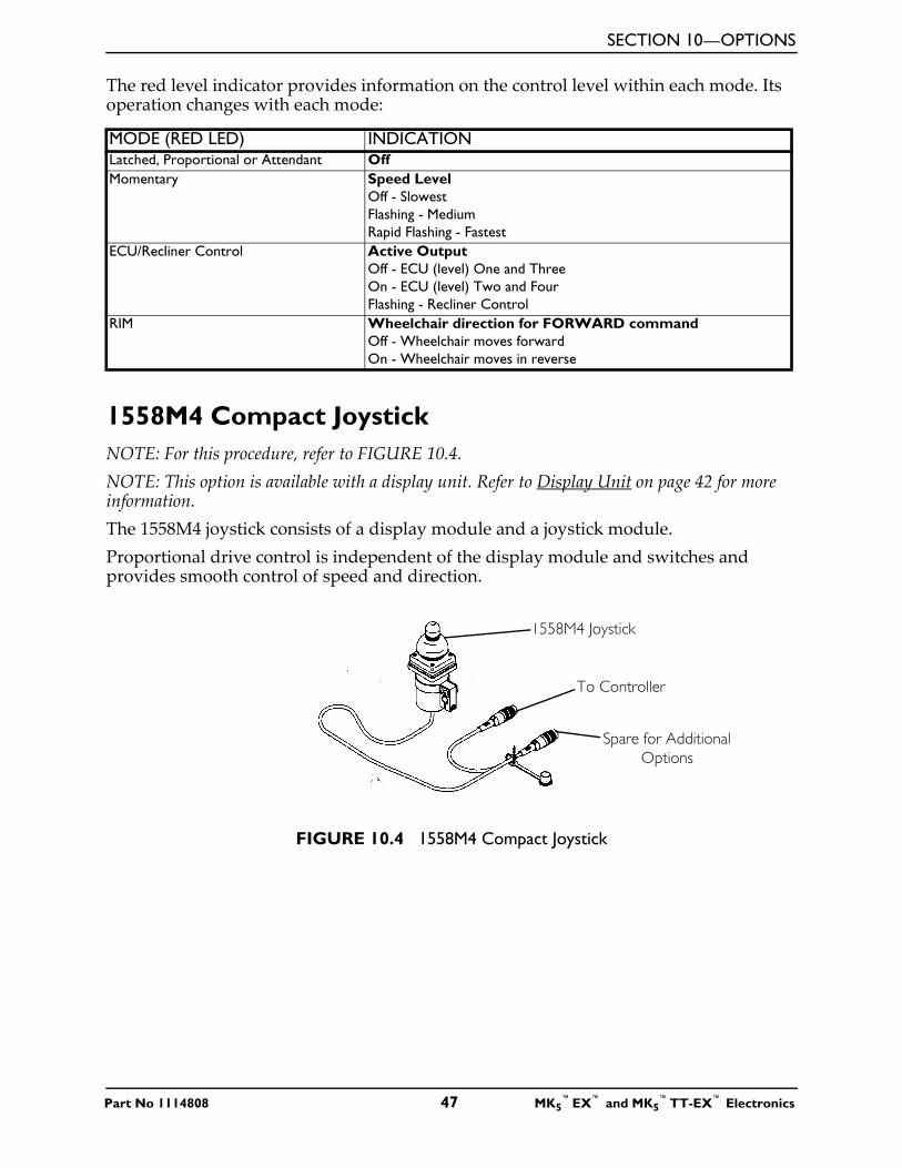
SECTION 10—OPTIONS
The red level indicator provides information on the control level within each mode. Its operation changes with each mode:
1558M4 Compact JoystickNOTE: For this procedure, refer to FIGURE 10.4.NOTE: This option is available with a display unit. Refer to Display Unit on page 42 for more information.The 1558M4 joystick consists of a display module and a joystick module.Proportional drive control is independent of the display module and switches and provides smooth control of speed and direction.
FIGURE 10.4 1558M4 Compact Joystick
MODE (RED LED) INDICATIONLatched, Proportional or Attendant OffMomentary Speed Level
Off - SlowestFlashing - MediumRapid Flashing - Fastest
ECU/Recliner Control Active OutputOff - ECU (level) One and ThreeOn - ECU (level) Two and FourFlashing - Recliner Control
RIM Wheelchair direction for FORWARD commandOff - Wheelchair moves forwardOn - Wheelchair moves in reverse
1558M4 Joystick
To Controller
Spare for Additional Options
Part No 1114808 47 MK5™EX™ and MK5
™TT-EX™ Electronics
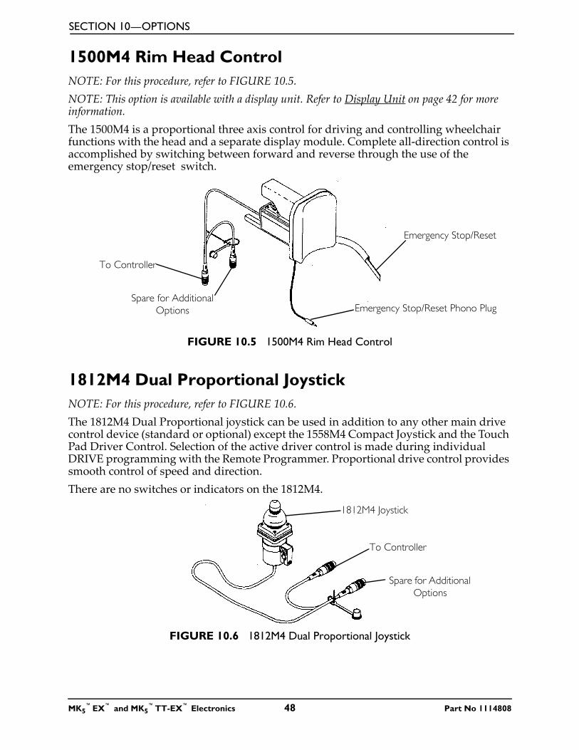
SECTION 10—OPTIONS
1500M4 Rim Head ControlNOTE: For this procedure, refer to FIGURE 10.5.NOTE: This option is available with a display unit. Refer to Display Unit on page 42 for more information.The 1500M4 is a proportional three axis control for driving and controlling wheelchair functions with the head and a separate display module. Complete all-direction control is accomplished by switching between forward and reverse through the use of the emergency stop/reset switch.
FIGURE 10.5 1500M4 Rim Head Control
1812M4 Dual Proportional JoystickNOTE: For this procedure, refer to FIGURE 10.6.The 1812M4 Dual Proportional joystick can be used in addition to any other main drive control device (standard or optional) except the 1558M4 Compact Joystick and the Touch Pad Driver Control. Selection of the active driver control is made during individual DRIVE programming with the Remote Programmer. Proportional drive control provides smooth control of speed and direction.There are no switches or indicators on the 1812M4.
FIGURE 10.6 1812M4 Dual Proportional Joystick
Emergency Stop/Reset
Emergency Stop/Reset Phono Plug
To Controller
Spare for Additional Options
1812M4 Joystick
To Controller
Spare for Additional Options
MK5™EX™ and MK5
™TT-EX™ Electronics 48 Part No 1114808
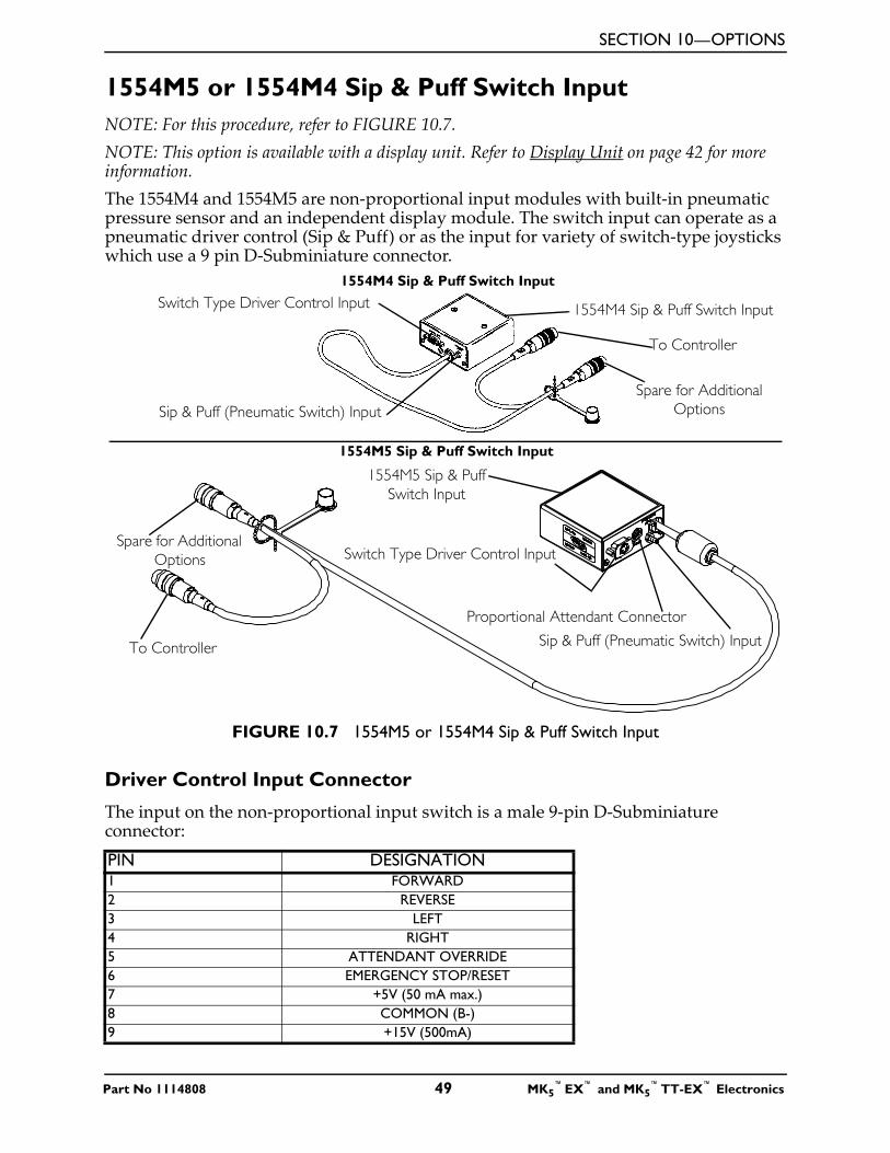
SECTION 10—OPTIONS
1554M5 or 1554M4 Sip & Puff Switch InputNOTE: For this procedure, refer to FIGURE 10.7.NOTE: This option is available with a display unit. Refer to Display Unit on page 42 for more information.The 1554M4 and 1554M5 are non-proportional input modules with built-in pneumatic pressure sensor and an independent display module. The switch input can operate as a pneumatic driver control (Sip & Puff) or as the input for variety of switch-type joysticks which use a 9 pin D-Subminiature connector.
FIGURE 10.7 1554M5 or 1554M4 Sip & Puff Switch Input
Driver Control Input Connector
The input on the non-proportional input switch is a male 9-pin D-Subminiature connector:PIN DESIGNATION1 FORWARD2 REVERSE3 LEFT4 RIGHT5 ATTENDANT OVERRIDE6 EMERGENCY STOP/RESET7 +5V (50 mA max.)8 COMMON (B-)9 +15V (500mA)
To Controller
Spare for Additional Options
1554M4 Sip & Puff Switch Input
1554M4 Sip & Puff Switch Input
1554M5 Sip & Puff Switch Input
To Controller
Spare for Additional Options
1554M5 Sip & Puff Switch Input
Switch Type Driver Control Input
Sip & Puff (Pneumatic Switch) Input
Sip & Puff (Pneumatic Switch) Input
Switch Type Driver Control Input
Proportional Attendant Connector
Part No 1114808 49 MK5™EX™ and MK5
™TT-EX™ Electronics
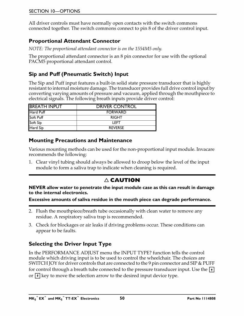
SECTION 10—OPTIONS
All driver controls must have normally open contacts with the switch commons connected together. The switch commons connect to pin 8 of the driver control input.
Proportional Attendant ConnectorNOTE: The proportional attendant connector is on the 1554M5 only.The proportional attendant connector is an 8 pin connector for use with the optional PACM5 proportional attendant control.
Sip and Puff (Pneumatic Switch) Input
The Sip and Puff input features a built-in solid state pressure transducer that is highly resistant to internal moisture damage. The transducer provides full drive control input by converting varying amounts of pressure and vacuum, applied through the mouthpiece to electrical signals. The following breath inputs provide driver control:
Mounting Precautions and Maintenance
Various mounting methods can be used for the non-proportional input module. Invacare recommends the following:1. Clear vinyl tubing should always be allowed to droop below the level of the input
module to form a saliva trap to indicate when cleaning is required.
� CAUTIONNEVER allow water to penetrate the input module case as this can result in damage to the internal electronics. Excessive amounts of saliva residue in the mouth piece can degrade performance.
2. Flush the mouthpiece/breath tube occasionally with clean water to remove any residue. A respiratory saliva trap is recommended.
3. Check for blockages or air leaks if driving problems occur. These conditions can appear to be faults.
Selecting the Driver Input Type
In the PERFORMANCE ADJUST menu the INPUT TYPE? function tells the control module which driving input is to be used to control the wheelchair. The choices are SWITCH JOY for driver controls that are connected to the 9 pin connector and SIP & PUFF for control through a breath tube connected to the pressure transducer input. Use the or key to move the selection arrow to the desired input device type.
BREATH INPUT DRIVER CONTROLHard Puff FORWARDSoft Puff RIGHTSoft Sip LEFTHard Sip REVERSE
MK5™EX™ and MK5
™TT-EX™ Electronics 50 Part No 1114808
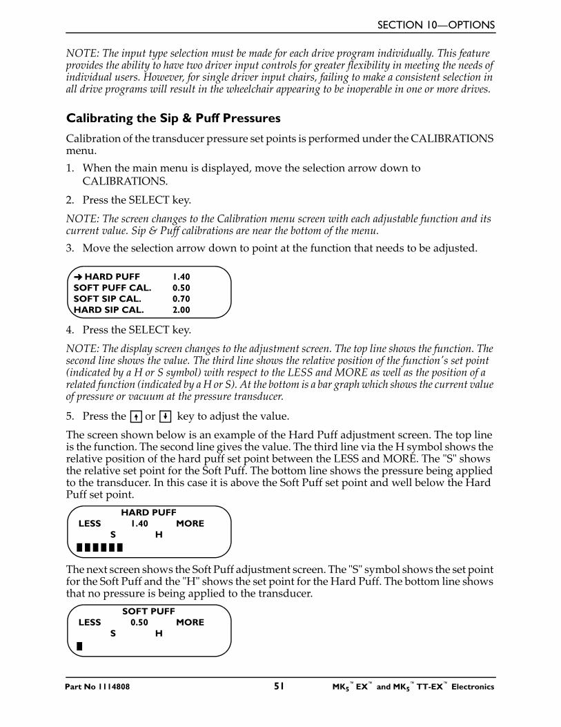
SECTION 10—OPTIONS
NOTE: The input type selection must be made for each drive program individually. This feature provides the ability to have two driver input controls for greater flexibility in meeting the needs of individual users. However, for single driver input chairs, failing to make a consistent selection in all drive programs will result in the wheelchair appearing to be inoperable in one or more drives.
Calibrating the Sip & Puff Pressures
Calibration of the transducer pressure set points is performed under the CALIBRATIONS menu. 1. When the main menu is displayed, move the selection arrow down to
CALIBRATIONS.
2. Press the SELECT key.
NOTE: The screen changes to the Calibration menu screen with each adjustable function and its current value. Sip & Puff calibrations are near the bottom of the menu. 3. Move the selection arrow down to point at the function that needs to be adjusted.
4. Press the SELECT key.
NOTE: The display screen changes to the adjustment screen. The top line shows the function. The second line shows the value. The third line shows the relative position of the function's set point (indicated by a H or S symbol) with respect to the LESS and MORE as well as the position of a related function (indicated by a H or S). At the bottom is a bar graph which shows the current value of pressure or vacuum at the pressure transducer.
5. Press the or key to adjust the value.
The screen shown below is an example of the Hard Puff adjustment screen. The top line is the function. The second line gives the value. The third line via the H symbol shows the relative position of the hard puff set point between the LESS and MORE. The "S" shows the relative set point for the Soft Puff. The bottom line shows the pressure being applied to the transducer. In this case it is above the Soft Puff set point and well below the Hard Puff set point.
The next screen shows the Soft Puff adjustment screen. The "S" symbol shows the set point for the Soft Puff and the "H" shows the set point for the Hard Puff. The bottom line shows that no pressure is being applied to the transducer.
➜ HARD PUFF 1.40SOFT PUFF CAL. 0.50SOFT SIP CAL. 0.70HARD SIP CAL. 2.00
HARD PUFFLESS 1.40 MORE
S H
SOFT PUFFLESS 0.50 MORE
S H
Part No 1114808 51 MK5™EX™ and MK5
™TT-EX™ Electronics
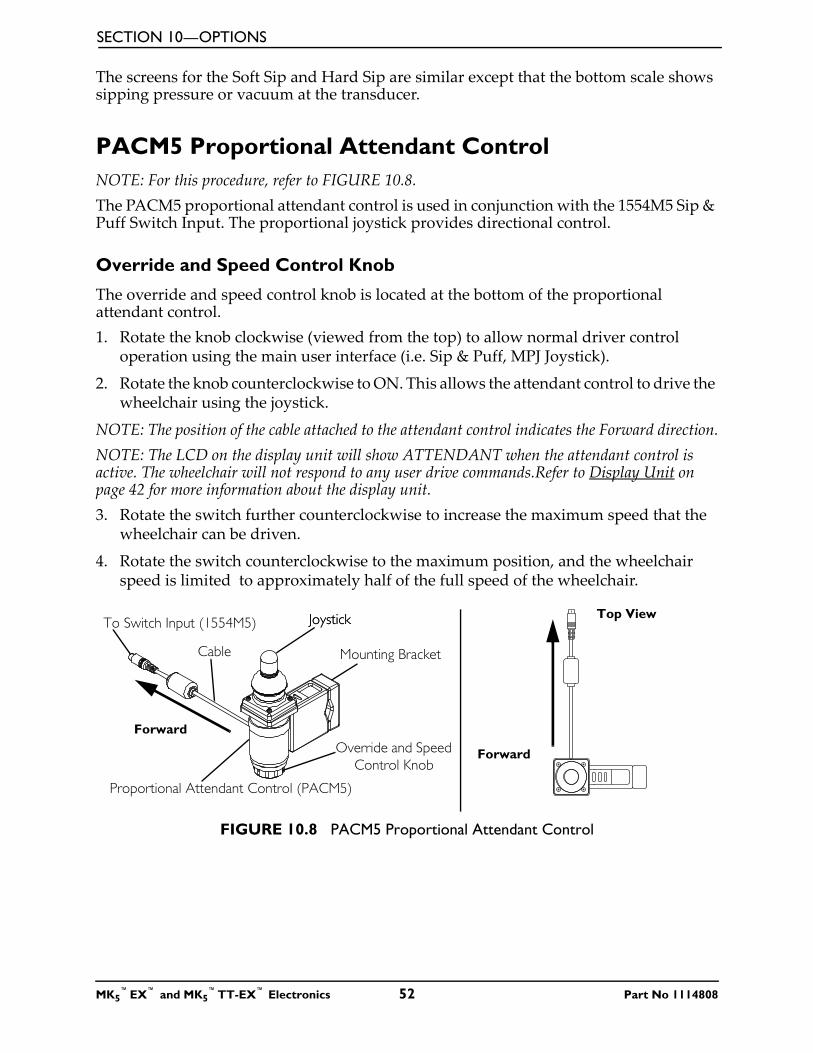
SECTION 10—OPTIONS
The screens for the Soft Sip and Hard Sip are similar except that the bottom scale shows sipping pressure or vacuum at the transducer.
PACM5 Proportional Attendant ControlNOTE: For this procedure, refer to FIGURE 10.8.The PACM5 proportional attendant control is used in conjunction with the 1554M5 Sip & Puff Switch Input. The proportional joystick provides directional control.
Override and Speed Control Knob
The override and speed control knob is located at the bottom of the proportional attendant control. 1. Rotate the knob clockwise (viewed from the top) to allow normal driver control
operation using the main user interface (i.e. Sip & Puff, MPJ Joystick).
2. Rotate the knob counterclockwise to ON. This allows the attendant control to drive the wheelchair using the joystick.
NOTE: The position of the cable attached to the attendant control indicates the Forward direction.NOTE: The LCD on the display unit will show ATTENDANT when the attendant control is active. The wheelchair will not respond to any user drive commands.Refer to Display Unit on page 42 for more information about the display unit.3. Rotate the switch further counterclockwise to increase the maximum speed that the
wheelchair can be driven.
4. Rotate the switch counterclockwise to the maximum position, and the wheelchair speed is limited to approximately half of the full speed of the wheelchair.
FIGURE 10.8 PACM5 Proportional Attendant Control
Proportional Attendant Control (PACM5)
To Switch Input (1554M5) Joystick
Override and Speed Control Knob
Forward
Top View
Forward
Joystick
Cable Mounting Bracket
MK5™EX™ and MK5
™TT-EX™ Electronics 52 Part No 1114808
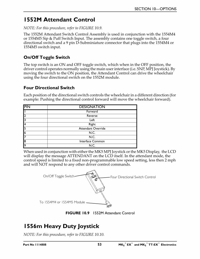
SECTION 10—OPTIONS
1552M Attendant ControlNOTE: For this procedure, refer to FIGURE 10.9.The 1552M Attendant Switch Control Assembly is used in conjunction with the 1554M4 or 1554M5 Sip & Puff Switch Input. The assembly contains one toggle switch, a four directional switch and a 9 pin D-Subminiature connector that plugs into the 1554M4 or 1554M5 switch input.
On/Off Toggle Switch
The top switch is an ON and OFF toggle switch, which when in the OFF position, the driver control operates normally using the main user interface (i.e. SNP, MPJ Joystick). By moving the switch to the ON position, the Attendant Control can drive the wheelchair using the four directional switch on the 1552M module.
Four Directional Switch
Each position of the directional switch controls the wheelchair in a different direction (for example: Pushing the directional control forward will move the wheelchair forward).
When used in conjunction with either the MK5 MPJ Joystick or the MK5 Display, the LCD will display the message ATTENDANT on the LCD itself. In the attendant mode, the control speed is limited to a fixed non-programmable low speed setting, less then 2 mph and will NOT respond to any other driver control commands.
FIGURE 10.9 1552M Attendant Control
1556m Heavy Duty JoystickNOTE: For this procedure, refer to FIGURE 10.10.
PIN DESIGNATION1 Forward2 Reverse3 Left4 Right5 Attendant Override6 N.C.7 N.C.8 Interface Common9 N.C.
Four Directional Switch Control
To 1554M4 or 1554M5 Module
On/Off Toggle Switch
Part No 1114808 53 MK5™EX™ and MK5
™TT-EX™ Electronics
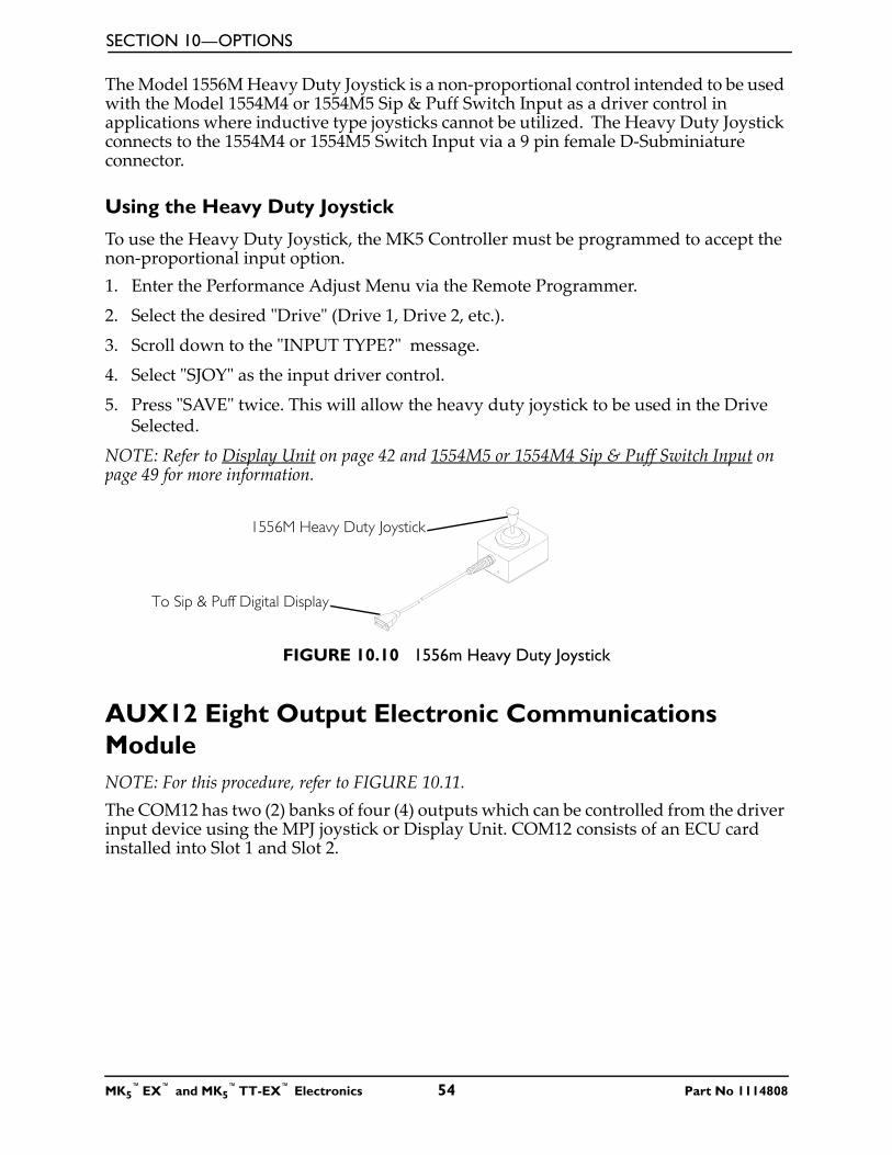
SECTION 10—OPTIONS
The Model 1556M Heavy Duty Joystick is a non-proportional control intended to be used with the Model 1554M4 or 1554M5 Sip & Puff Switch Input as a driver control in applications where inductive type joysticks cannot be utilized. The Heavy Duty Joystick connects to the 1554M4 or 1554M5 Switch Input via a 9 pin female D-Subminiature connector.
Using the Heavy Duty Joystick
To use the Heavy Duty Joystick, the MK5 Controller must be programmed to accept the non-proportional input option. 1. Enter the Performance Adjust Menu via the Remote Programmer.
2. Select the desired "Drive" (Drive 1, Drive 2, etc.).
3. Scroll down to the "INPUT TYPE?" message.
4. Select "SJOY" as the input driver control.
5. Press "SAVE" twice. This will allow the heavy duty joystick to be used in the Drive Selected.
NOTE: Refer to Display Unit on page 42 and 1554M5 or 1554M4 Sip & Puff Switch Input on page 49 for more information.
FIGURE 10.10 1556m Heavy Duty Joystick
AUX12 Eight Output Electronic Communications ModuleNOTE: For this procedure, refer to FIGURE 10.11.The COM12 has two (2) banks of four (4) outputs which can be controlled from the driver input device using the MPJ joystick or Display Unit. COM12 consists of an ECU card installed into Slot 1 and Slot 2.
1556M Heavy Duty Joystick
To Sip & Puff Digital Display
MK5™EX™ and MK5
™TT-EX™ Electronics 54 Part No 1114808
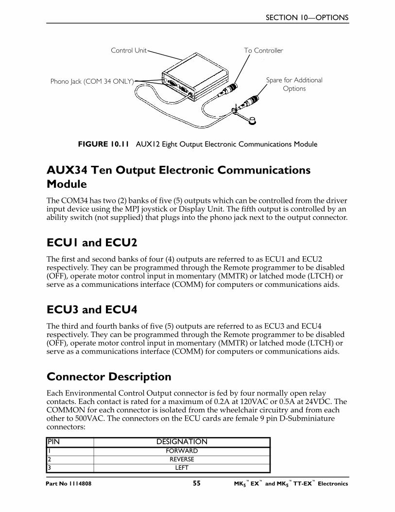
SECTION 10—OPTIONS
FIGURE 10.11 AUX12 Eight Output Electronic Communications Module
AUX34 Ten Output Electronic Communications ModuleThe COM34 has two (2) banks of five (5) outputs which can be controlled from the driver input device using the MPJ joystick or Display Unit. The fifth output is controlled by an ability switch (not supplied) that plugs into the phono jack next to the output connector.
ECU1 and ECU2The first and second banks of four (4) outputs are referred to as ECU1 and ECU2 respectively. They can be programmed through the Remote programmer to be disabled (OFF), operate motor control input in momentary (MMTR) or latched mode (LTCH) or serve as a communications interface (COMM) for computers or communications aids.
ECU3 and ECU4The third and fourth banks of five (5) outputs are referred to as ECU3 and ECU4 respectively. They can be programmed through the Remote programmer to be disabled (OFF), operate motor control input in momentary (MMTR) or latched mode (LTCH) or serve as a communications interface (COMM) for computers or communications aids.
Connector DescriptionEach Environmental Control Output connector is fed by four normally open relay contacts. Each contact is rated for a maximum of 0.2A at 120VAC or 0.5A at 24VDC. The COMMON for each connector is isolated from the wheelchair circuitry and from each other to 500VAC. The connectors on the ECU cards are female 9 pin D-Subminiature connectors:
PIN DESIGNATION1 FORWARD2 REVERSE3 LEFT
Control Unit
Phono Jack (COM 34 ONLY)
To Controller
Spare for Additional Options
Part No 1114808 55 MK5™EX™ and MK5
™TT-EX™ Electronics
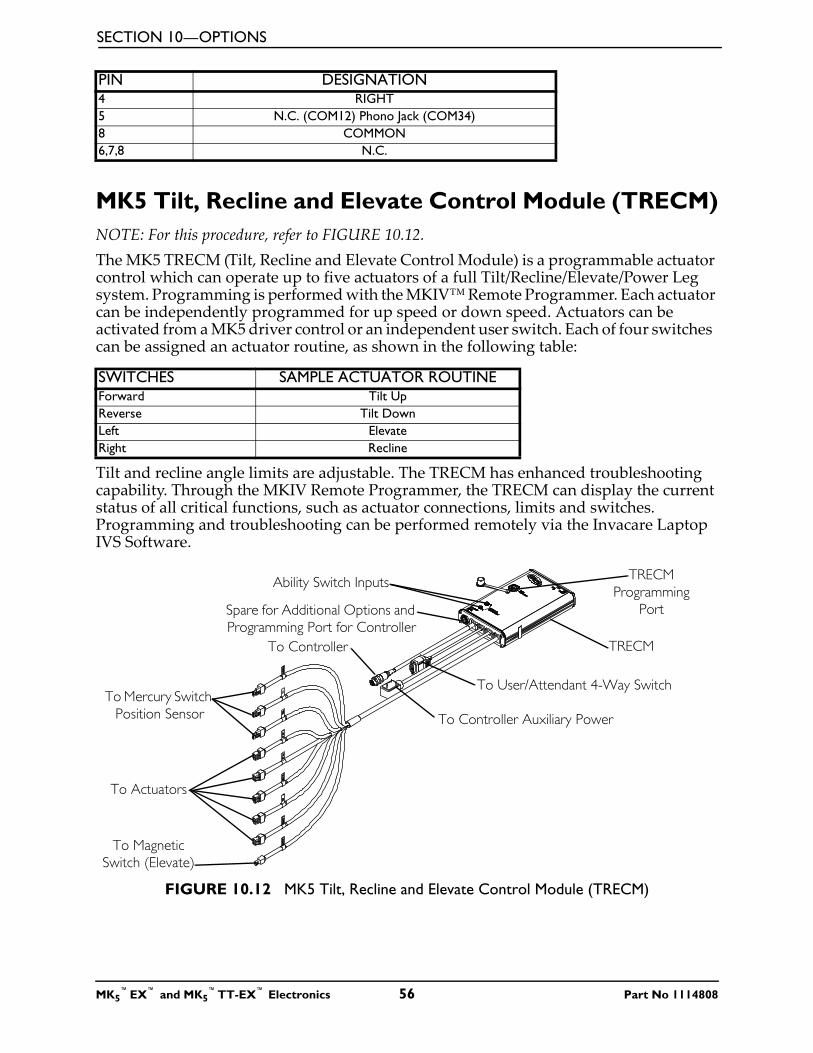
SECTION 10—OPTIONS
MK5 Tilt, Recline and Elevate Control Module (TRECM)NOTE: For this procedure, refer to FIGURE 10.12.The MK5 TRECM (Tilt, Recline and Elevate Control Module) is a programmable actuator control which can operate up to five actuators of a full Tilt/Recline/Elevate/Power Leg system. Programming is performed with the MKIV™ Remote Programmer. Each actuator can be independently programmed for up speed or down speed. Actuators can be activated from a MK5 driver control or an independent user switch. Each of four switches can be assigned an actuator routine, as shown in the following table:
Tilt and recline angle limits are adjustable. The TRECM has enhanced troubleshooting capability. Through the MKIV Remote Programmer, the TRECM can display the current status of all critical functions, such as actuator connections, limits and switches. Programming and troubleshooting can be performed remotely via the Invacare Laptop IVS Software.
FIGURE 10.12 MK5 Tilt, Recline and Elevate Control Module (TRECM)
4 RIGHT5 N.C. (COM12) Phono Jack (COM34)8 COMMON6,7,8 N.C.
SWITCHES SAMPLE ACTUATOR ROUTINEForward Tilt UpReverse Tilt DownLeft ElevateRight Recline
PIN DESIGNATION
TRECM
Spare for Additional Options and Programming Port for Controller
To Controller Auxiliary Power
Ability Switch Inputs TRECM Programming
Port
To Mercury Switch Position Sensor
To User/Attendant 4-Way Switch
To Controller
To Actuators
To Magnetic Switch (Elevate)
MK5™EX™ and MK5
™TT-EX™ Electronics 56 Part No 1114808
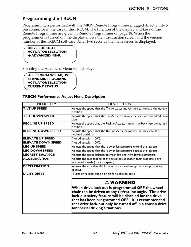
SECTION 10—OPTIONS
Programming the TRECM
Programming is performed with the MKIV Remote Programmer plugged directly into 5 pin connector in the case of the TRECM. The function of the display and keys of the Remote Programmer are given in Remote Programmer on page 18. When the programmer is turned on, the display shows the introduction screen and the version number of the TRECM software. After two seconds the main screen is displayed.
Selecting the Advanced Menu will display:
TRECM Performance Adjust Menu Description
MENU ITEM DESCRIPTIONTILT UP SPEED Adjusts the speed that the Tilt Actuator moves the seat toward the upright
position.TILT DOWN SPEED Adjusts the speed that the Tilt Actuator moves the seat into the tilted posi-
tion.RECLINE UP SPEED Adjusts the speed that the Recline Actuator moves the back into the upright
position.RECLINE DOWN SPEED Adjusts the speed that the Recline Actuator moves the back into the
reclined position.ELEVATE UP SPEED Not adjustable - 100%.ELEVATE DOWN SPEED Not adjustable - 100%.LEG UP SPEED Adjusts the speed that the power leg actuators extend the legrests.LEG DOWN SPEED Adjusts the speed that the power leg actuators retract the legrests.LEGREST BALANCE Adjusts the speed balance between left and right legrest actuators.ACCELERATION Adjusts the rate that all of the actuators approach their respective pro-
grammed speeds (Start up speed).DECELERATION Adjusts the rate that all of the actuators are brought to a stop (Braking
speed.).D/L BY DRIVE Turns drive lock-out on or off for a chosen drive.
� WARNING When drive lock-out is programmed OFF the wheel-chair can be driven at any tilt/recline angle. The drive lock-out safety feature will be disabled for the drive that has been programmed OFF. It is recommended that drive lock-out only be turned off in a chosen drive for special driving situations.
DRIVE LOCKOUTACTUATOR SELECTION➜ ADVANCED MENU
➜ PERFORMANCE ADJUSTSTANDARD PROGRAMSACTUATOR SELECTIONCURRENT STATUS
Part No 1114808 57 MK5™EX™ and MK5
™TT-EX™ Electronics
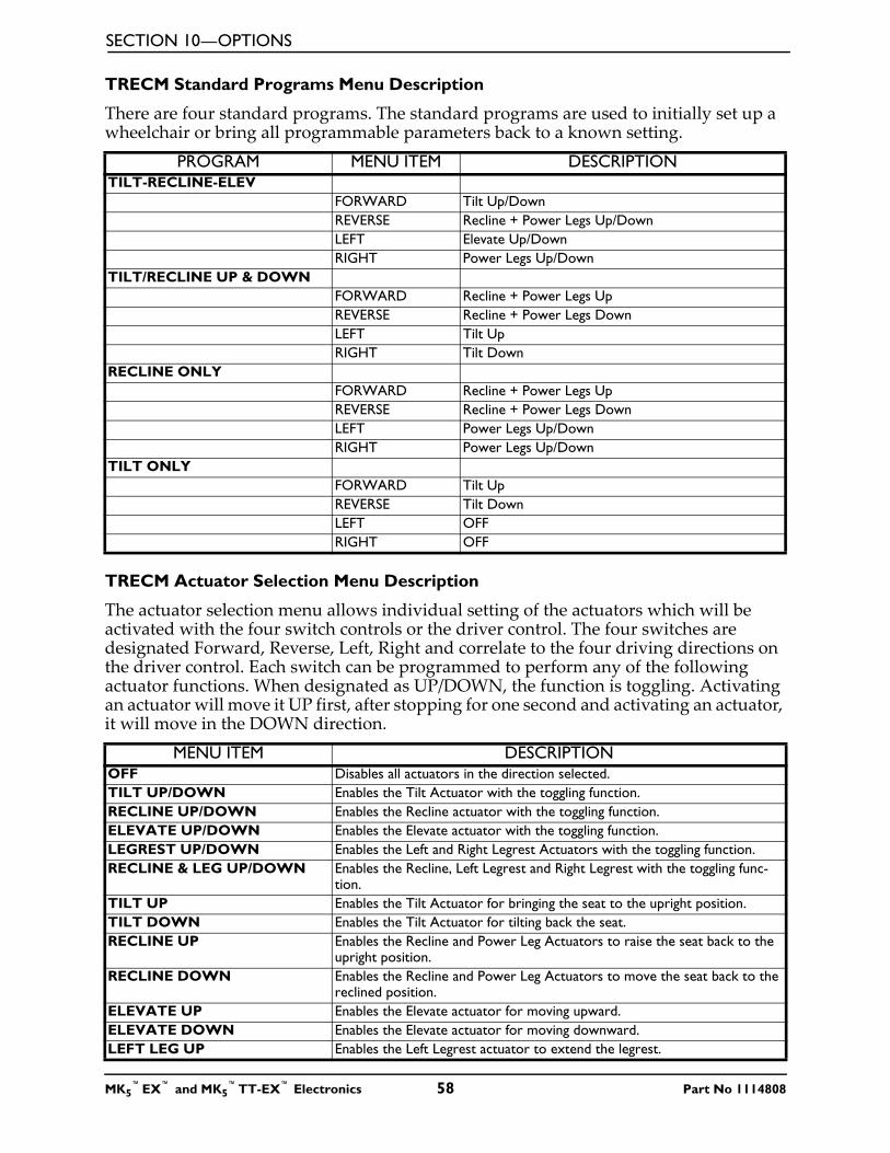
SECTION 10—OPTIONS
TRECM Standard Programs Menu Description
There are four standard programs. The standard programs are used to initially set up a wheelchair or bring all programmable parameters back to a known setting.
TRECM Actuator Selection Menu Description
The actuator selection menu allows individual setting of the actuators which will be activated with the four switch controls or the driver control. The four switches are designated Forward, Reverse, Left, Right and correlate to the four driving directions on the driver control. Each switch can be programmed to perform any of the following actuator functions. When designated as UP/DOWN, the function is toggling. Activating an actuator will move it UP first, after stopping for one second and activating an actuator, it will move in the DOWN direction.
PROGRAM MENU ITEM DESCRIPTIONTILT-RECLINE-ELEV
FORWARD Tilt Up/DownREVERSE Recline + Power Legs Up/DownLEFT Elevate Up/DownRIGHT Power Legs Up/Down
TILT/RECLINE UP & DOWNFORWARD Recline + Power Legs UpREVERSE Recline + Power Legs DownLEFT Tilt UpRIGHT Tilt Down
RECLINE ONLYFORWARD Recline + Power Legs UpREVERSE Recline + Power Legs DownLEFT Power Legs Up/DownRIGHT Power Legs Up/Down
TILT ONLYFORWARD Tilt UpREVERSE Tilt DownLEFT OFFRIGHT OFF
MENU ITEM DESCRIPTIONOFF Disables all actuators in the direction selected.TILT UP/DOWN Enables the Tilt Actuator with the toggling function.RECLINE UP/DOWN Enables the Recline actuator with the toggling function.ELEVATE UP/DOWN Enables the Elevate actuator with the toggling function.LEGREST UP/DOWN Enables the Left and Right Legrest Actuators with the toggling function.RECLINE & LEG UP/DOWN Enables the Recline, Left Legrest and Right Legrest with the toggling func-
tion.TILT UP Enables the Tilt Actuator for bringing the seat to the upright position.TILT DOWN Enables the Tilt Actuator for tilting back the seat.RECLINE UP Enables the Recline and Power Leg Actuators to raise the seat back to the
upright position.RECLINE DOWN Enables the Recline and Power Leg Actuators to move the seat back to the
reclined position.ELEVATE UP Enables the Elevate actuator for moving upward.ELEVATE DOWN Enables the Elevate actuator for moving downward.LEFT LEG UP Enables the Left Legrest actuator to extend the legrest.
MK5™EX™ and MK5
™TT-EX™ Electronics 58 Part No 1114808
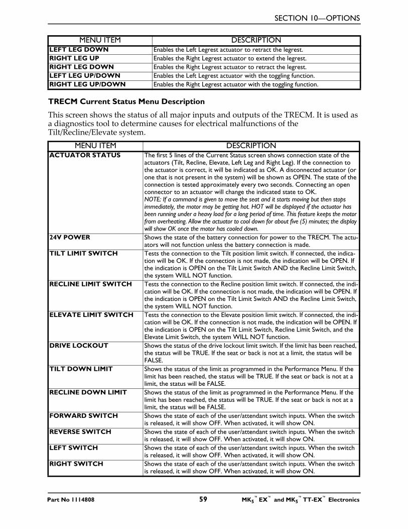
SECTION 10—OPTIONS
TRECM Current Status Menu Description
This screen shows the status of all major inputs and outputs of the TRECM. It is used as a diagnostics tool to determine causes for electrical malfunctions of the Tilt/Recline/Elevate system.
LEFT LEG DOWN Enables the Left Legrest actuator to retract the legrest.RIGHT LEG UP Enables the Right Legrest actuator to extend the legrest.RIGHT LEG DOWN Enables the Right Legrest actuator to retract the legrest.LEFT LEG UP/DOWN Enables the Left Legrest actuator with the toggling function.RIGHT LEG UP/DOWN Enables the Right Legrest actuator with the toggling function.
MENU ITEM DESCRIPTIONACTUATOR STATUS The first 5 lines of the Current Status screen shows connection state of the
actuators (Tilt, Recline, Elevate, Left Leg and Right Leg). If the connection to the actuator is correct, it will be indicated as OK. A disconnected actuator (or one that is not present in the system) will be shown as OPEN. The state of the connection is tested approximately every two seconds. Connecting an open connector to an actuator will change the indicated state to OK. NOTE: If a command is given to move the seat and it starts moving but then stops immediately, the motor may be getting hot. HOT will be displayed if the actuator has been running under a heavy load for a long period of time. This feature keeps the motor from overheating. Allow the actuator to cool down for about five (5) minutes; the display will show OK once the motor has cooled down.
24V POWER Shows the state of the battery connection for power to the TRECM. The actu-ators will not function unless the battery connection is made.
TILT LIMIT SWITCH Tests the connection to the Tilt position limit switch. If connected, the indica-tion will be OK. If the connection is not made, the indication will be OPEN. If the indication is OPEN on the Tilt Limit Switch AND the Recline Limit Switch, the system WILL NOT function.
RECLINE LIMIT SWITCH Tests the connection to the Recline position limit switch. If connected, the indi-cation will be OK. If the connection is not made, the indication will be OPEN. If the indication is OPEN on the Tilt Limit Switch AND the Recline Limit Switch, the system WILL NOT function.
ELEVATE LIMIT SWITCH Tests the connection to the Elevate position limit switch. If connected, the indi-cation will be OK. If the connection is not made, the indication will be OPEN. If the indication is OPEN on the Tilt Limit Switch, Recline Limit Switch, and the Elevate Limit Switch, the system WILL NOT function.
DRIVE LOCKOUT Shows the status of the drive lockout limit switch. If the limit has been reached, the status will be TRUE. If the seat or back is not at a limit, the status will be FALSE.
TILT DOWN LIMIT Shows the status of the limit as programmed in the Performance Menu. If the limit has been reached, the status will be TRUE. If the seat or back is not at a limit, the status will be FALSE.
RECLINE DOWN LIMIT Shows the status of the limit as programmed in the Performance Menu. If the limit has been reached, the status will be TRUE. If the seat or back is not at a limit, the status will be FALSE.
FORWARD SWITCH Shows the state of each of the user/attendant switch inputs. When the switch is released, it will show OFF. When activated, it will show ON.
REVERSE SWITCH Shows the state of each of the user/attendant switch inputs. When the switch is released, it will show OFF. When activated, it will show ON.
LEFT SWITCH Shows the state of each of the user/attendant switch inputs. When the switch is released, it will show OFF. When activated, it will show ON.
RIGHT SWITCH Shows the state of each of the user/attendant switch inputs. When the switch is released, it will show OFF. When activated, it will show ON.
MENU ITEM DESCRIPTION
Part No 1114808 59 MK5™EX™ and MK5
™TT-EX™ Electronics
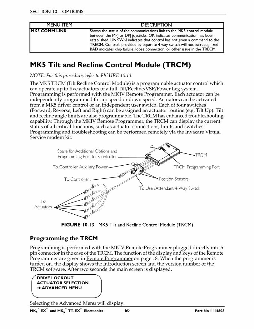
SECTION 10—OPTIONS
MK5 Tilt and Recline Control Module (TRCM)NOTE: For this procedure, refer to FIGURE 10.13.The MK5 TRCM (Tilt Recline Control Module) is a programmable actuator control which can operate up to five actuators of a full Tilt/Recline/VSR/Power Leg system. Programming is performed with the MKIV Remote Programmer. Each actuator can be independently programmed for up speed or down speed. Actuators can be activated from a MK5 driver control or an independent user switch. Each of four switches (Forward, Reverse, Left and Right) can be assigned an actuator routine (e.g. Tilt Up). Tilt and recline angle limits are also programmable. The TRCM has enhanced troubleshooting capability. Through the MKIV Remote Programmer, the TRCM can display the current status of all critical functions, such as actuator connections, limits and switches. Programming and troubleshooting can be performed remotely via the Invacare Virtual Service modem kit.
FIGURE 10.13 MK5 Tilt and Recline Control Module (TRCM)
Programming the TRCM
Programming is performed with the MKIV Remote Programmer plugged directly into 5 pin connector in the case of the TRCM. The function of the display and keys of the Remote Programmer are given in Remote Programmer on page 18. When the programmer is turned on, the display shows the introduction screen and the version number of the TRCM software. After two seconds the main screen is displayed.
Selecting the Advanced Menu will display:
MK5 COMM LINK Shows the status of the communications link to the MK5 control module between the MPJ or DPJ joysticks. OK indicates communication has been established. UNKWN indicates that control has not given a command to the TRECM. Controls provided by separate 4 way switch will not be recognized BAD indicates chip failure, loose connection, or other issue in the TRECM.
MENU ITEM DESCRIPTION
TRCMSpare for Additional Options and Programming Port for Controller
To Controller Auxiliary Power TRCM Programming Port
Position Sensors
To User/Attendant 4-Way Switch
To Controller
To Actuators
DRIVE LOCKOUTACTUATOR SELECTION➜ ADVANCED MENU
MK5™EX™ and MK5
™TT-EX™ Electronics 60 Part No 1114808
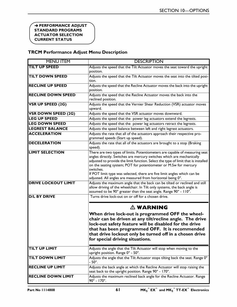
SECTION 10—OPTIONS
TRCM Performance Adjust Menu Description
MENU ITEM DESCRIPTIONTILT UP SPEED Adjusts the speed that the Tilt Actuator moves the seat toward the upright
position.TILT DOWN SPEED Adjusts the speed that the Tilt Actuator moves the seat into the tilted posi-
tion.RECLINE UP SPEED Adjusts the speed that the Recline Actuator moves the back into the upright
position.RECLINE DOWN SPEED Adjusts the speed that the Recline Actuator moves the back into the
reclined position.VSR UP SPEED (2G) Adjusts the speed that the Vernier Shear Reduction (VSR) actuator moves
upward.VSR DOWN SPEED (2G) Adjusts the speed that the VSR actuator moves downward.LEG UP SPEED Adjusts the speed that the power leg actuators extend the legrests.LEG DOWN SPEED Adjusts the speed that the power leg actuators retract the legrests.LEGREST BALANCE Adjusts the speed balance between left and right legrest actuators.ACCELERATION Adjusts the rate that all of the actuators approach their respective pro-
grammed speeds (Start up speed).DECELERATION Adjusts the rate that all of the actuators are brought to a stop (Braking
speed).LIMIT SELECTION There are two types of limits. Potentiometers are capable of measuring seat
angles directly. Switches are mercury switches which are mechanically adjusted to provide the limit function. Select the type of limit that is installed on the seating system; POT for potentiometer or M.Sw for mercury switches.If POT limit type was selected, there are five limit angles which can be adjusted. All angles are measured from horizontal being 0°.
DRIVE LOCKOUT LIMIT Adjusts the maximum angle that the back can be tilted or reclined and still allow driving of the wheelchair. In Tilt only systems, the back angle is assumed to be 90° greater than the seat angle. Range 90° - 110°.
D/L BY DRIVE Turns drive lock-out on or off for a chosen drive.
� WARNING When drive lock-out is programmed OFF the wheel-chair can be driven at any tilt/recline angle. The drive lock-out safety feature will be disabled for the drive that has been programmed OFF. It is recommended that drive lockout only be turned off in a chosen drive for special driving situations.
TILT UP LIMIT Adjusts the angle that the Tilt Actuator will stop when moving to the upright position. Range 0° - 50°.
TILT DOWN LIMIT Adjusts the angle that the Tilt Actuator stops tilting back the seat. Range 0° - 50°.
RECLINE UP LIMIT Adjusts the back angle at which the Recline Actuator will stop raising the seat back to the upright position. Range 90° - 170°.
RECLINE DOWN LIMIT Adjusts the maximum reclined back angle for the Recline Actuator. Range 90° - 170°.
➜ PERFORMANCE ADJUSTSTANDARD PROGRAMSACTUATOR SELECTIONCURRENT STATUS
Part No 1114808 61 MK5™EX™ and MK5
™TT-EX™ Electronics
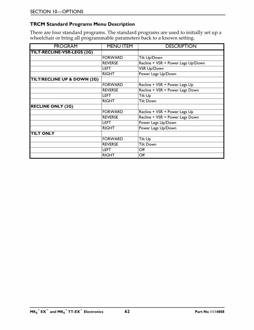
SECTION 10—OPTIONS
TRCM Standard Programs Menu Description
There are four standard programs. The standard programs are used to initially set up a wheelchair or bring all programmable parameters back to a known setting.
PROGRAM MENU ITEM DESCRIPTIONTILT-RECLINE-VSR-LEGS (2G)
FORWARD Tilt Up/DownREVERSE Recline + VSR + Power Legs Up/DownLEFT VSR Up/DownRIGHT Power Legs Up/Down
TILT/RECLINE UP & DOWN (2G)FORWARD Recline + VSR + Power Legs UpREVERSE Recline + VSR + Power Legs DownLEFT Tilt UpRIGHT Tilt Down
RECLINE ONLY (2G)FORWARD Recline + VSR + Power Legs UpREVERSE Recline + VSR + Power Legs DownLEFT Power Legs Up/DownRIGHT Power Legs Up/Down
TILT ONLYFORWARD Tilt UpREVERSE Tilt DownLEFT OffRIGHT Off
MK5™EX™ and MK5
™TT-EX™ Electronics 62 Part No 1114808
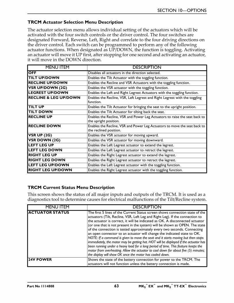
SECTION 10—OPTIONS
TRCM Actuator Selection Menu Description
The actuator selection menu allows individual setting of the actuators which will be activated with the four switch controls or the driver control. The four switches are designated Forward, Reverse, Left, Right and correlate to the four driving directions on the driver control. Each switch can be programmed to perform any of the following actuator functions. When designated as UP/DOWN, the function is toggling. Activating an actuator will move it UP first, after stopping for one second and activating an actuator, it will move in the DOWN direction.
TRCM Current Status Menu DescriptionThis screen shows the status of all major inputs and outputs of the TRCM. It is used as a diagnostics tool to determine causes for electrical malfunctions of the Tilt/Recline system.
MENU ITEM DESCRIPTIONOFF Disables all actuators in the direction selected.TILT UP/DOWN Enables the Tilt Actuator with the toggling function.RECLINE UP/DOWN Enables the Recline and VSR Actuators with the toggling function.VSR UP/DOWN (2G) Enables the VSR actuator with the toggling function.LEGREST UP/DOWN Enables the Left and Right Legrest Actuators with the toggling function.RECLINE & LEG UP/DOWN Enables the Recline, VSR, Left Legrest and Right Legrest with the toggling
function.TILT UP Enables the Tilt Actuator for bringing the seat to the upright position.TILT DOWN Enables the Tilt Actuator for tilting back the seat.RECLINE UP Enables the Recline, VSR and Power Leg Actuators to raise the seat back to
the upright position.RECLINE DOWN Enables the Recline, VSR and Power Leg Actuators to move the seat back to
the reclined position.VSR UP (2G) Enables the VSR actuator for moving upward.VSR DOWN (2G) Enables the VSR actuator for moving downward.LEFT LEG UP Enables the Left Legrest actuator to extend the legrest.LEFT LEG DOWN Enables the Left Legrest actuator to retract the legrest.RIGHT LEG UP Enables the Right Legrest actuator to extend the legrest.RIGHT LEG DOWN Enables the Right Legrest actuator to retract the legrest.LEFT LEG UP/DOWN Enables the Left Legrest actuator with the toggling function.RIGHT LEG UP/DOWN Enables the Right Legrest actuator with the toggling function.
MENU ITEM DESCRIPTIONACTUATOR STATUS The first 5 lines of the Current Status screen shows connection state of the
actuators (Tilt, Recline, VSR, Left Leg and Right Leg). If the connection to the actuator is correct, it will be indicated as OK. A disconnected actuator (or one that is not present in the system) will be shown as OPEN. The state of the connection is tested approximately every two seconds. Connecting an open connector to an actuator will change the indicated state to OK. NOTE: If a command is given to move the seat and it starts moving but then stops immediately, the motor may be getting hot. HOT will be displayed if the actuator has been running under a heavy load for a long period of time. This feature keeps the motor from overheating. Allow the actuator to cool down for about five (5) minutes; the display will show OK once the motor has cooled down.
24V POWER Shows the state of the battery connection for power to the TRCM. The actuators will not function unless the battery connection is made.
Part No 1114808 63 MK5™EX™ and MK5
™TT-EX™ Electronics
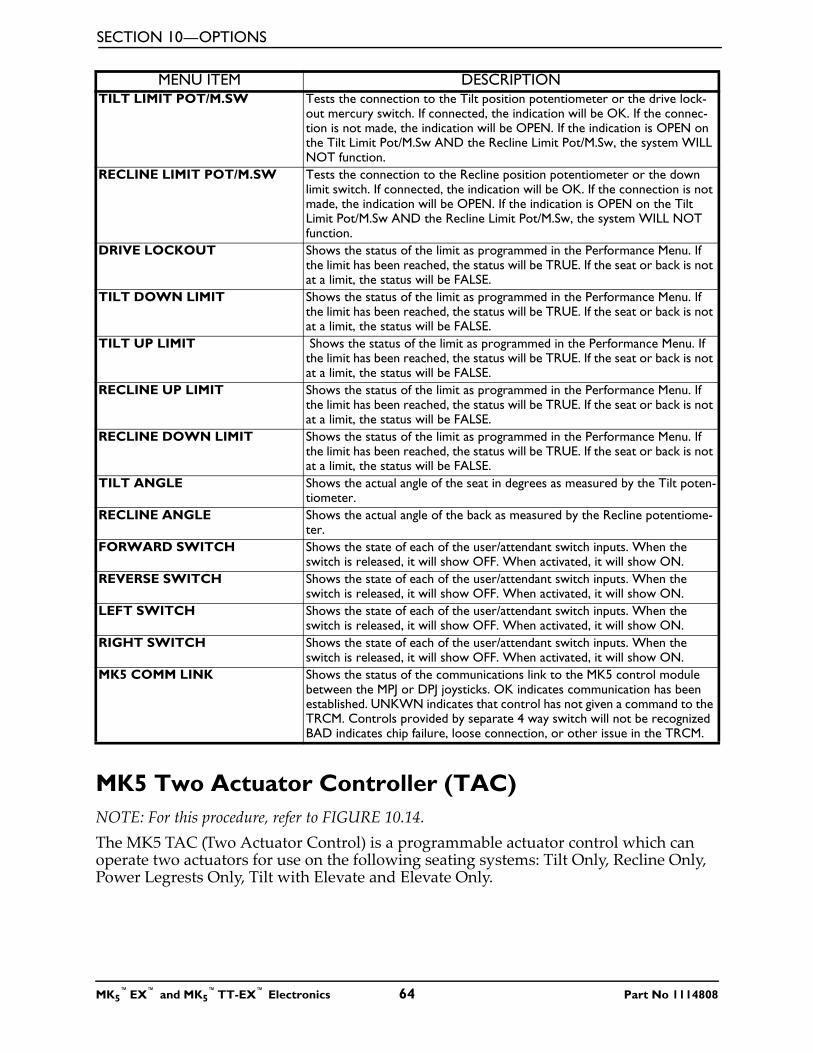
SECTION 10—OPTIONS
MK5 Two Actuator Controller (TAC)NOTE: For this procedure, refer to FIGURE 10.14.The MK5 TAC (Two Actuator Control) is a programmable actuator control which can operate two actuators for use on the following seating systems: Tilt Only, Recline Only, Power Legrests Only, Tilt with Elevate and Elevate Only.
TILT LIMIT POT/M.SW Tests the connection to the Tilt position potentiometer or the drive lock-out mercury switch. If connected, the indication will be OK. If the connec-tion is not made, the indication will be OPEN. If the indication is OPEN on the Tilt Limit Pot/M.Sw AND the Recline Limit Pot/M.Sw, the system WILL NOT function.
RECLINE LIMIT POT/M.SW Tests the connection to the Recline position potentiometer or the down limit switch. If connected, the indication will be OK. If the connection is not made, the indication will be OPEN. If the indication is OPEN on the Tilt Limit Pot/M.Sw AND the Recline Limit Pot/M.Sw, the system WILL NOT function.
DRIVE LOCKOUT Shows the status of the limit as programmed in the Performance Menu. If the limit has been reached, the status will be TRUE. If the seat or back is not at a limit, the status will be FALSE.
TILT DOWN LIMIT Shows the status of the limit as programmed in the Performance Menu. If the limit has been reached, the status will be TRUE. If the seat or back is not at a limit, the status will be FALSE.
TILT UP LIMIT Shows the status of the limit as programmed in the Performance Menu. If the limit has been reached, the status will be TRUE. If the seat or back is not at a limit, the status will be FALSE.
RECLINE UP LIMIT Shows the status of the limit as programmed in the Performance Menu. If the limit has been reached, the status will be TRUE. If the seat or back is not at a limit, the status will be FALSE.
RECLINE DOWN LIMIT Shows the status of the limit as programmed in the Performance Menu. If the limit has been reached, the status will be TRUE. If the seat or back is not at a limit, the status will be FALSE.
TILT ANGLE Shows the actual angle of the seat in degrees as measured by the Tilt poten-tiometer.
RECLINE ANGLE Shows the actual angle of the back as measured by the Recline potentiome-ter.
FORWARD SWITCH Shows the state of each of the user/attendant switch inputs. When the switch is released, it will show OFF. When activated, it will show ON.
REVERSE SWITCH Shows the state of each of the user/attendant switch inputs. When the switch is released, it will show OFF. When activated, it will show ON.
LEFT SWITCH Shows the state of each of the user/attendant switch inputs. When the switch is released, it will show OFF. When activated, it will show ON.
RIGHT SWITCH Shows the state of each of the user/attendant switch inputs. When the switch is released, it will show OFF. When activated, it will show ON.
MK5 COMM LINK Shows the status of the communications link to the MK5 control module between the MPJ or DPJ joysticks. OK indicates communication has been established. UNKWN indicates that control has not given a command to the TRCM. Controls provided by separate 4 way switch will not be recognized BAD indicates chip failure, loose connection, or other issue in the TRCM.
MENU ITEM DESCRIPTION
MK5™EX™ and MK5
™TT-EX™ Electronics 64 Part No 1114808
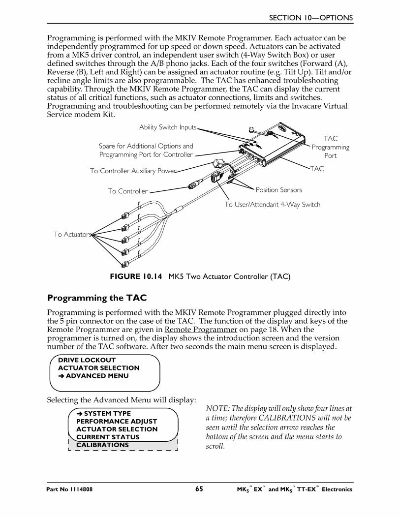
SECTION 10—OPTIONS
Programming is performed with the MKIV Remote Programmer. Each actuator can be independently programmed for up speed or down speed. Actuators can be activated from a MK5 driver control, an independent user switch (4-Way Switch Box) or user defined switches through the A/B phono jacks. Each of the four switches (Forward (A), Reverse (B), Left and Right) can be assigned an actuator routine (e.g. Tilt Up). Tilt and/or recline angle limits are also programmable. The TAC has enhanced troubleshooting capability. Through the MKIV Remote Programmer, the TAC can display the current status of all critical functions, such as actuator connections, limits and switches. Programming and troubleshooting can be performed remotely via the Invacare Virtual Service modem Kit.
FIGURE 10.14 MK5 Two Actuator Controller (TAC)
Programming the TAC
Programming is performed with the MKIV Remote Programmer plugged directly into the 5 pin connector on the case of the TAC. The function of the display and keys of the Remote Programmer are given in Remote Programmer on page 18. When the programmer is turned on, the display shows the introduction screen and the version number of the TAC software. After two seconds the main menu screen is displayed.
Selecting the Advanced Menu will display:NOTE: The display will only show four lines at a time; therefore CALIBRATIONS will not be seen until the selection arrow reaches the bottom of the screen and the menu starts to scroll.
TAC
Spare for Additional Options and Programming Port for Controller
To Controller Auxiliary Power
Ability Switch Inputs
TAC Programming
Port
Position Sensors
To User/Attendant 4-Way Switch
To Controller
To Actuators
DRIVE LOCKOUTACTUATOR SELECTION➜ ADVANCED MENU
➜ SYSTEM TYPEPERFORMANCE ADJUST ACTUATOR SELECTIONCURRENT STATUSCALIBRATIONS
Part No 1114808 65 MK5™EX™ and MK5
™TT-EX™ Electronics
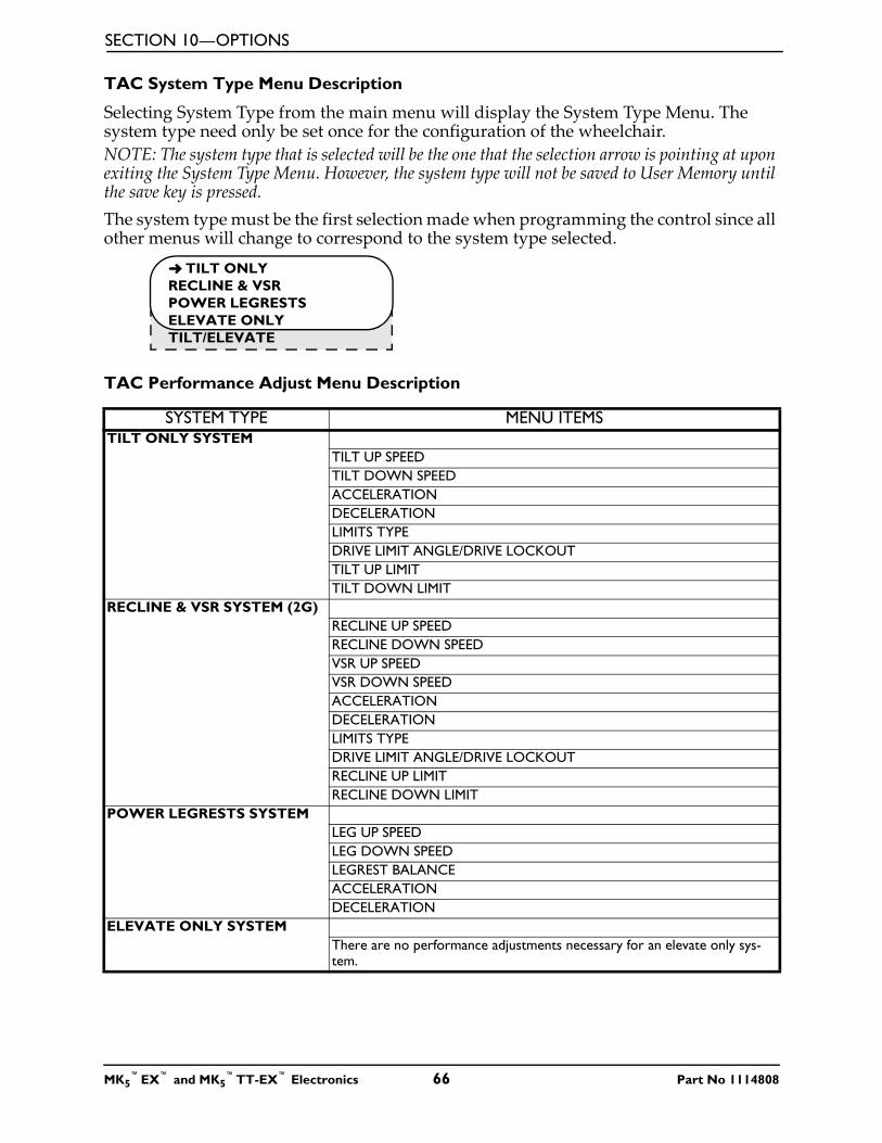
SECTION 10—OPTIONS
TAC System Type Menu Description
Selecting System Type from the main menu will display the System Type Menu. The system type need only be set once for the configuration of the wheelchair.NOTE: The system type that is selected will be the one that the selection arrow is pointing at upon exiting the System Type Menu. However, the system type will not be saved to User Memory until the save key is pressed.The system type must be the first selection made when programming the control since all other menus will change to correspond to the system type selected.
TAC Performance Adjust Menu Description
SYSTEM TYPE MENU ITEMSTILT ONLY SYSTEM
TILT UP SPEED TILT DOWN SPEEDACCELERATION DECELERATIONLIMITS TYPEDRIVE LIMIT ANGLE/DRIVE LOCKOUTTILT UP LIMITTILT DOWN LIMIT
RECLINE & VSR SYSTEM (2G)RECLINE UP SPEEDRECLINE DOWN SPEEDVSR UP SPEEDVSR DOWN SPEEDACCELERATIONDECELERATIONLIMITS TYPEDRIVE LIMIT ANGLE/DRIVE LOCKOUTRECLINE UP LIMITRECLINE DOWN LIMIT
POWER LEGRESTS SYSTEMLEG UP SPEEDLEG DOWN SPEEDLEGREST BALANCEACCELERATIONDECELERATION
ELEVATE ONLY SYSTEMThere are no performance adjustments necessary for an elevate only sys-tem.
➜ TILT ONLYRECLINE & VSRPOWER LEGRESTSELEVATE ONLYTILT/ELEVATE
MK5™EX™ and MK5
™TT-EX™ Electronics 66 Part No 1114808
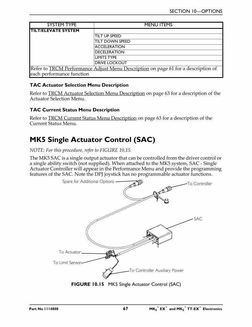
SECTION 10—OPTIONS
TAC Actuator Selection Menu Description
Refer to TRCM Actuator Selection Menu Description on page 63 for a description of the Actuator Selection Menu.
TAC Current Status Menu Description
Refer to TRCM Current Status Menu Description on page 63 for a description of the Current Status Menu.
MK5 Single Actuator Control (SAC)NOTE: For this procedure, refer to FIGURE 10.15.The MK5 SAC is a single output actuator that can be controlled from the driver control or a single ability switch (not supplied). When attached to the MK5 system, SAC - Single Actuator Controller will appear in the Performance Menu and provide the programming features of the SAC. Note the DPJ joystick has no programmable actuator functions.
FIGURE 10.15 MK5 Single Actuator Control (SAC)
TILT/ELEVATE SYSTEMTILT UP SPEEDTILT DOWN SPEEDACCELERATIONDECELERATIONLIMITS TYPEDRIVE LOCKOUT
Refer to TRCM Performance Adjust Menu Description on page 61 for a description of each performance function
SYSTEM TYPE MENU ITEMS
SAC
To ControllerSpare for Additional Options
To Actuator
To Controller Auxiliary Power
To Limit Sensor
Part No 1114808 67 MK5™EX™ and MK5
™TT-EX™ Electronics
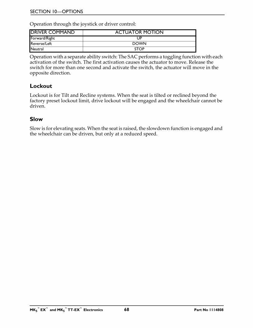
SECTION 10—OPTIONS
Operation through the joystick or driver control:
Operation with a separate ability switch: The SAC performs a toggling function with each activation of the switch. The first activation causes the actuator to move. Release the switch for more than one second and activate the switch, the actuator will move in the opposite direction.
Lockout
Lockout is for Tilt and Recline systems. When the seat is tilted or reclined beyond the factory preset lockout limit, drive lockout will be engaged and the wheelchair cannot be driven.
Slow
Slow is for elevating seats. When the seat is raised, the slowdown function is engaged and the wheelchair can be driven, but only at a reduced speed.
DRIVER COMMAND ACTUATOR MOTIONForward/Right UPReverse/Left DOWNNeutral STOP
MK5™EX™ and MK5
™TT-EX™ Electronics 68 Part No 1114808

SECTION 11—CALIBRATING POTENTIOMETERS
SECTION 11—CALIBRATING POTENTIOMETERSNOTE: This procedure applies to 2G Tarsys® Powered Seating Systems only.
Preparing to Calibrate PotentiometersThis screen allows you to calibrate the tilt and recline position feedback sensors (potentiometers). The potentiometers are adjusted at the factory, so this calibration should only be necessary if a potentiometer or TRCM/TAC Controller is damaged and must be replaced.
1. Rotate the potentiometer shaft completely clockwise (looking at the end of the shaft).
2. Rotate the shaft counterclockwise no more than 1/8 turn. 3. Tighten the set screw. The TRCM/TAC may now be calibrated using the Remote
Programmer.
Potentiometer Calibration for 2GTR Systems1. Select CALIBRATIONS from the main menu. The calibrations menu will be displayed.
2. Select the menu item that corresponds to the potentiometer to be adjusted. The up angle adjustment screen will then be displayed.
Tilt Angle Potentiometer Calibration
1. Position the seat back in the fully upright position.
2. Using a protractor or angle pitch calculator, measure the actual angle of the seat with respect to the floor. This measurement should will range from 0° to 10°.
3. Adjust the tilt up angle setting on the programmer to the measured angle. 4. Press the SELECT key on the programmer to proceed to the tilt down adjustment
screen.
5. Tilt the seat until the measured angle is approximately 50° and adjust the tilt down angle setting on the programmer to the measured angle. The range is 45° to 55°.
➜ TILT ANGLERECLINE ANGLE
TILT UP ANGLE5
PRESS SAVETO CONTINUE
Part No 1114808 69 MK5™EX™ and MK5
™TT-EX™ Electronics
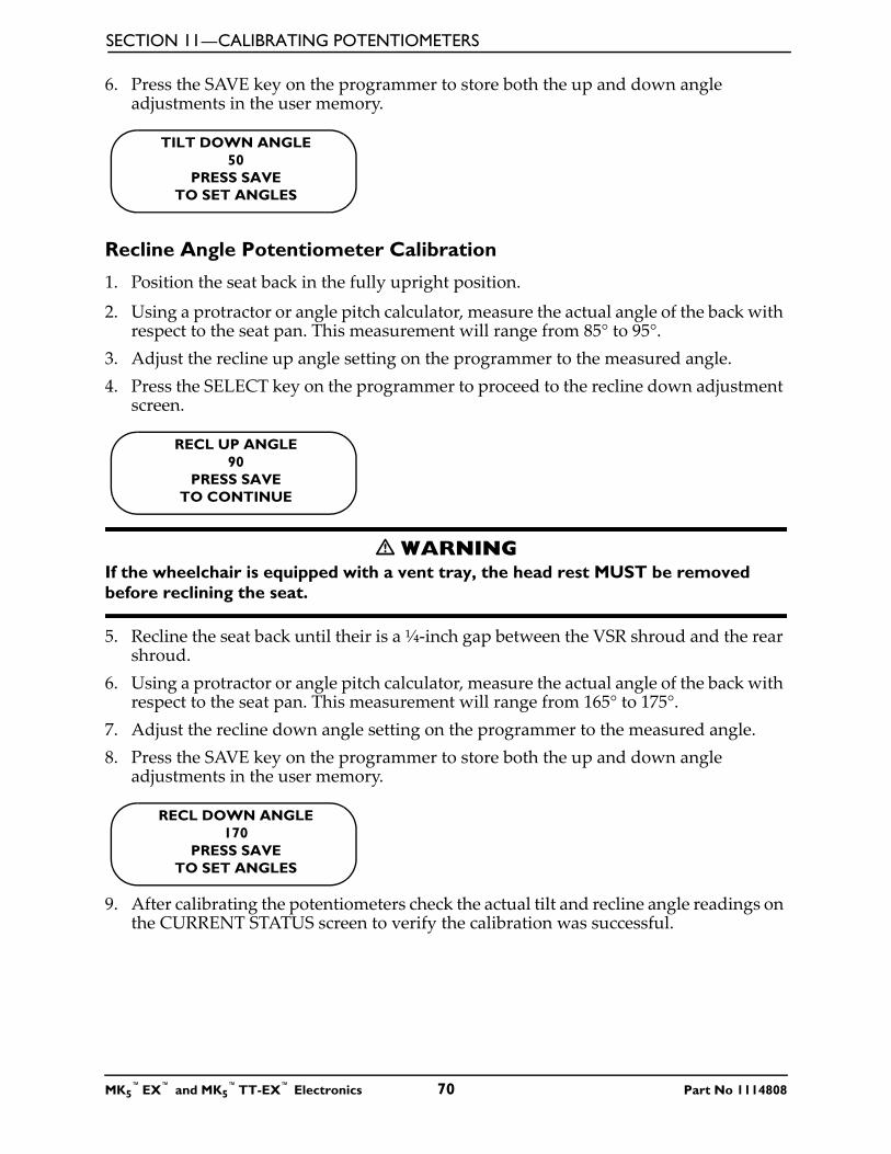
SECTION 11—CALIBRATING POTENTIOMETERS
6. Press the SAVE key on the programmer to store both the up and down angle adjustments in the user memory.
Recline Angle Potentiometer Calibration
1. Position the seat back in the fully upright position.
2. Using a protractor or angle pitch calculator, measure the actual angle of the back with respect to the seat pan. This measurement will range from 85° to 95°.
3. Adjust the recline up angle setting on the programmer to the measured angle. 4. Press the SELECT key on the programmer to proceed to the recline down adjustment
screen.
� WARNINGIf the wheelchair is equipped with a vent tray, the head rest MUST be removed before reclining the seat.
5. Recline the seat back until their is a ¼-inch gap between the VSR shroud and the rear shroud.
6. Using a protractor or angle pitch calculator, measure the actual angle of the back with respect to the seat pan. This measurement will range from 165° to 175°.
7. Adjust the recline down angle setting on the programmer to the measured angle. 8. Press the SAVE key on the programmer to store both the up and down angle
adjustments in the user memory.
9. After calibrating the potentiometers check the actual tilt and recline angle readings on the CURRENT STATUS screen to verify the calibration was successful.
TILT DOWN ANGLE50
PRESS SAVETO SET ANGLES
RECL UP ANGLE90
PRESS SAVETO CONTINUE
RECL DOWN ANGLE170
PRESS SAVETO SET ANGLES
MK5™EX™ and MK5
™TT-EX™ Electronics 70 Part No 1114808

SECTION 11—CALIBRATING POTENTIOMETERS
10. One of the following may occur:A. Calibration was successful.
B. Calibration was unsuccessful. If an error occurred during the calibration procedure an E06 or E07 warning message will scroll across the bottom of the programmer screen and the calibration values in user memory will be restored. Perform the following:
i. Try the calibration procedure again.
ii. If the warning message does not go away contact Invacare Technical Service for assistance.
Potentiometer Calibration for 2GT Systems1. Select CALIBRATIONS from the main menu. The calibrations menu will be displayed.
2. Select the menu item that corresponds to the potentiometer to be adjusted. The up angle adjustment screen will then be displayed.
Tilt Angle Potentiometer Calibration
1. Position the seat back in the fully upright position.
2. Using a protractor or angle pitch calculator, measure the actual angle of the seat with respect to the floor. This measurement should will range from 0° to 10°.
3. Adjust the tilt up angle setting on the programmer to the measured angle. 4. Press the SELECT key on the programmer to proceed to the tilt down adjustment
screen.
5. Tilt the seat until the measured angle is approximately 50°.6. Adjust the tilt down angle setting on the programmer to the measured angle. The
range is 45° to 55°. 7. Then press the SAVE key on the programmer to store both the up and down angle
adjustments in the user memory.
➜ TILT ANGLERECLINE ANGLE
TILT UP ANGLE5
PRESS SAVETO CONTINUE
TILT DOWN ANGLE50
PRESS SAVETO SET ANGLES
Part No 1114808 71 MK5™EX™ and MK5
™TT-EX™ Electronics
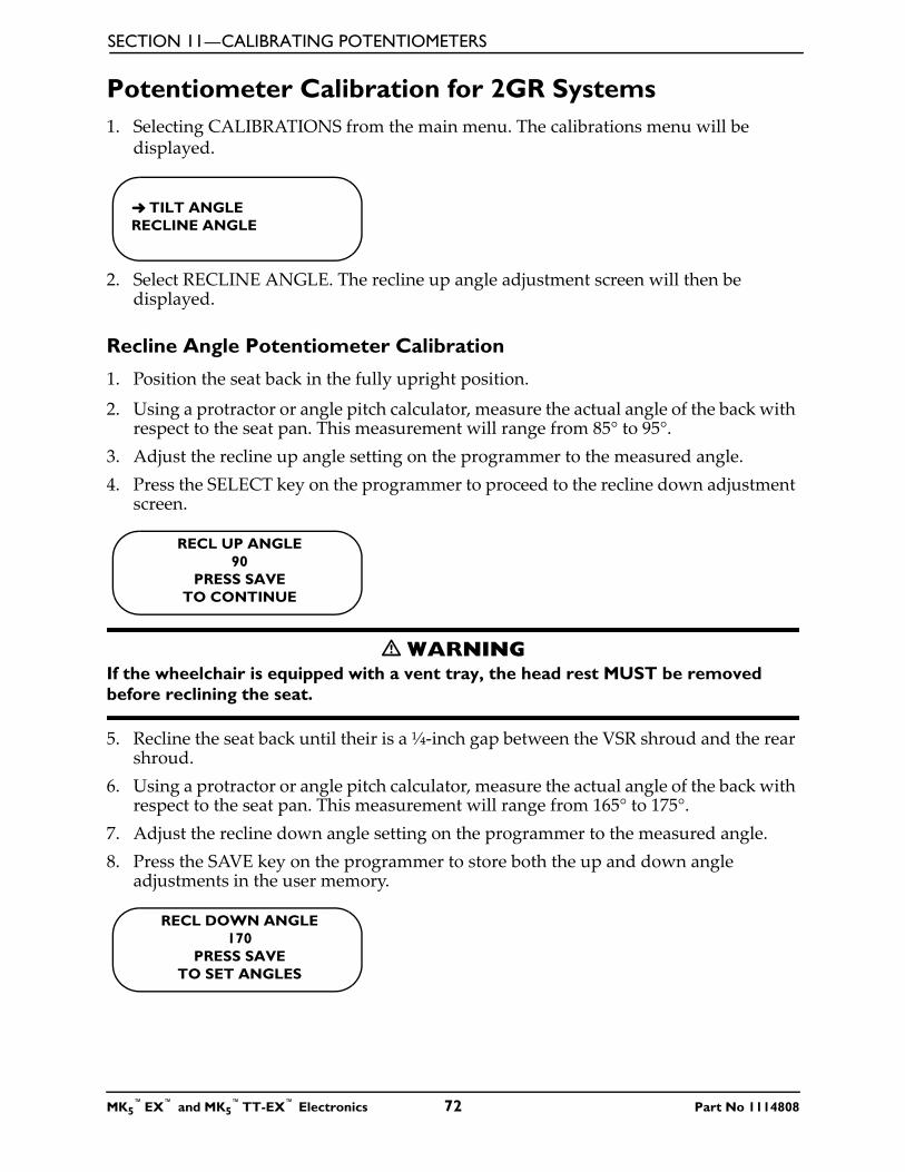
SECTION 11—CALIBRATING POTENTIOMETERS
Potentiometer Calibration for 2GR Systems1. Selecting CALIBRATIONS from the main menu. The calibrations menu will be
displayed.
2. Select RECLINE ANGLE. The recline up angle adjustment screen will then be displayed.
Recline Angle Potentiometer Calibration
1. Position the seat back in the fully upright position.
2. Using a protractor or angle pitch calculator, measure the actual angle of the back with respect to the seat pan. This measurement will range from 85° to 95°.
3. Adjust the recline up angle setting on the programmer to the measured angle. 4. Press the SELECT key on the programmer to proceed to the recline down adjustment
screen.
� WARNINGIf the wheelchair is equipped with a vent tray, the head rest MUST be removed before reclining the seat.
5. Recline the seat back until their is a ¼-inch gap between the VSR shroud and the rear shroud.
6. Using a protractor or angle pitch calculator, measure the actual angle of the back with respect to the seat pan. This measurement will range from 165° to 175°.
7. Adjust the recline down angle setting on the programmer to the measured angle. 8. Press the SAVE key on the programmer to store both the up and down angle
adjustments in the user memory.
➜ TILT ANGLERECLINE ANGLE
RECL UP ANGLE90
PRESS SAVETO CONTINUE
RECL DOWN ANGLE170
PRESS SAVETO SET ANGLES
MK5™EX™ and MK5
™TT-EX™ Electronics 72 Part No 1114808
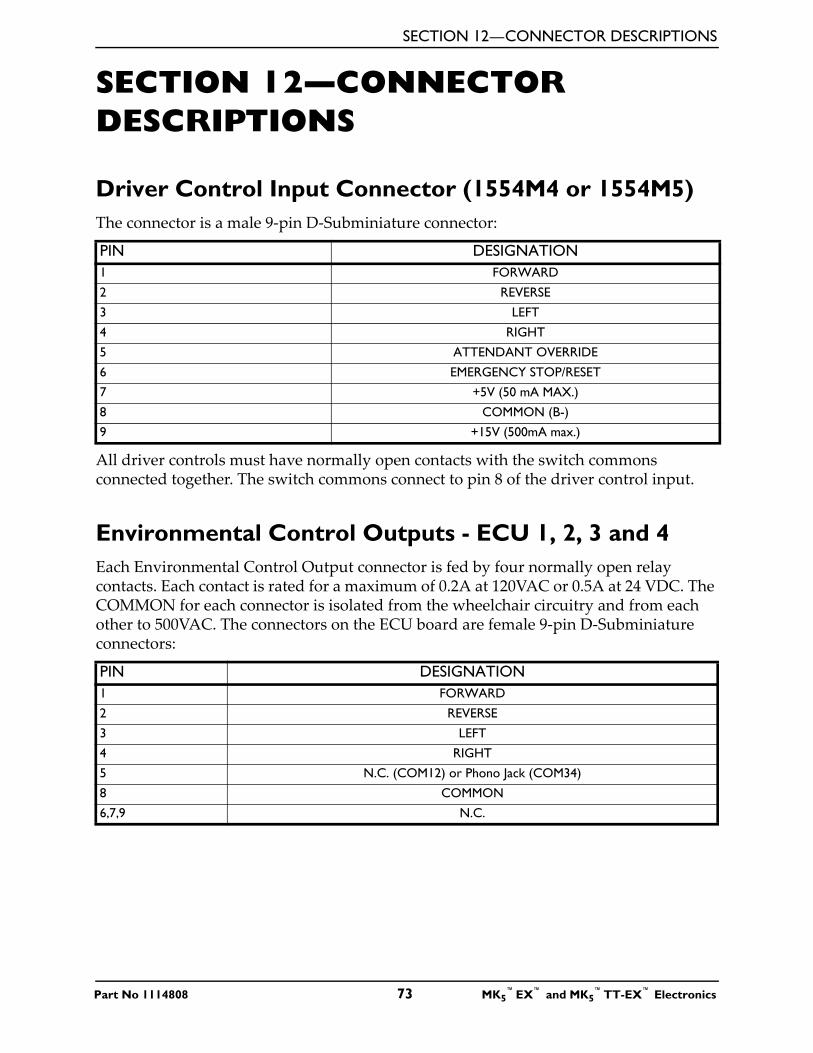
SECTION 12—CONNECTOR DESCRIPTIONS
SECTION 12—CONNECTOR DESCRIPTIONS
Driver Control Input Connector (1554M4 or 1554M5)The connector is a male 9-pin D-Subminiature connector:
All driver controls must have normally open contacts with the switch commons connected together. The switch commons connect to pin 8 of the driver control input.
Environmental Control Outputs - ECU 1, 2, 3 and 4Each Environmental Control Output connector is fed by four normally open relay contacts. Each contact is rated for a maximum of 0.2A at 120VAC or 0.5A at 24 VDC. The COMMON for each connector is isolated from the wheelchair circuitry and from each other to 500VAC. The connectors on the ECU board are female 9-pin D-Subminiature connectors:
PIN DESIGNATION1 FORWARD
2 REVERSE
3 LEFT
4 RIGHT
5 ATTENDANT OVERRIDE
6 EMERGENCY STOP/RESET
7 +5V (50 mA MAX.)
8 COMMON (B-)
9 +15V (500mA max.)
PIN DESIGNATION1 FORWARD
2 REVERSE
3 LEFT
4 RIGHT
5 N.C. (COM12) or Phono Jack (COM34)
8 COMMON
6,7,9 N.C.
Part No 1114808 73 MK5™EX™ and MK5
™TT-EX™ Electronics
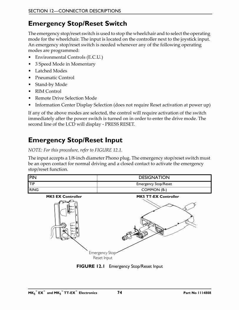
SECTION 12—CONNECTOR DESCRIPTIONS
Emergency Stop/Reset SwitchThe emergency stop/reset switch is used to stop the wheelchair and to select the operating mode for the wheelchair. The input is located on the controller next to the joystick input. An emergency stop/reset switch is needed whenever any of the following operating modes are programmed:• Environmental Controls (E.C.U.) • 3 Speed Mode in Momentary• Latched Modes• Pneumatic Control• Stand-by Mode• RIM Control• Remote Drive Selection Mode• Information Center Display Selection (does not require Reset activation at power up)
If any of the above modes are selected, the control will require activation of the switch immediately after the power switch is turned on in order to enter the drive mode. The second line of the LCD will display - PRESS RESET.
Emergency Stop/Reset InputNOTE: For this procedure, refer to FIGURE 12.1.
The input accepts a 1/8-inch diameter Phono plug. The emergency stop/reset switch must be an open contact for normal driving and a closed contact to activate the emergency stop/reset function.
FIGURE 12.1 Emergency Stop/Reset Input
PIN DESIGNATIONTIP Emergency Stop/Reset
RING COMMON (B-)
Emergency Stop Reset Input
MK5 EX Controller MK5 TT-EX Controller
MK5™EX™ and MK5
™TT-EX™ Electronics 74 Part No 1114808
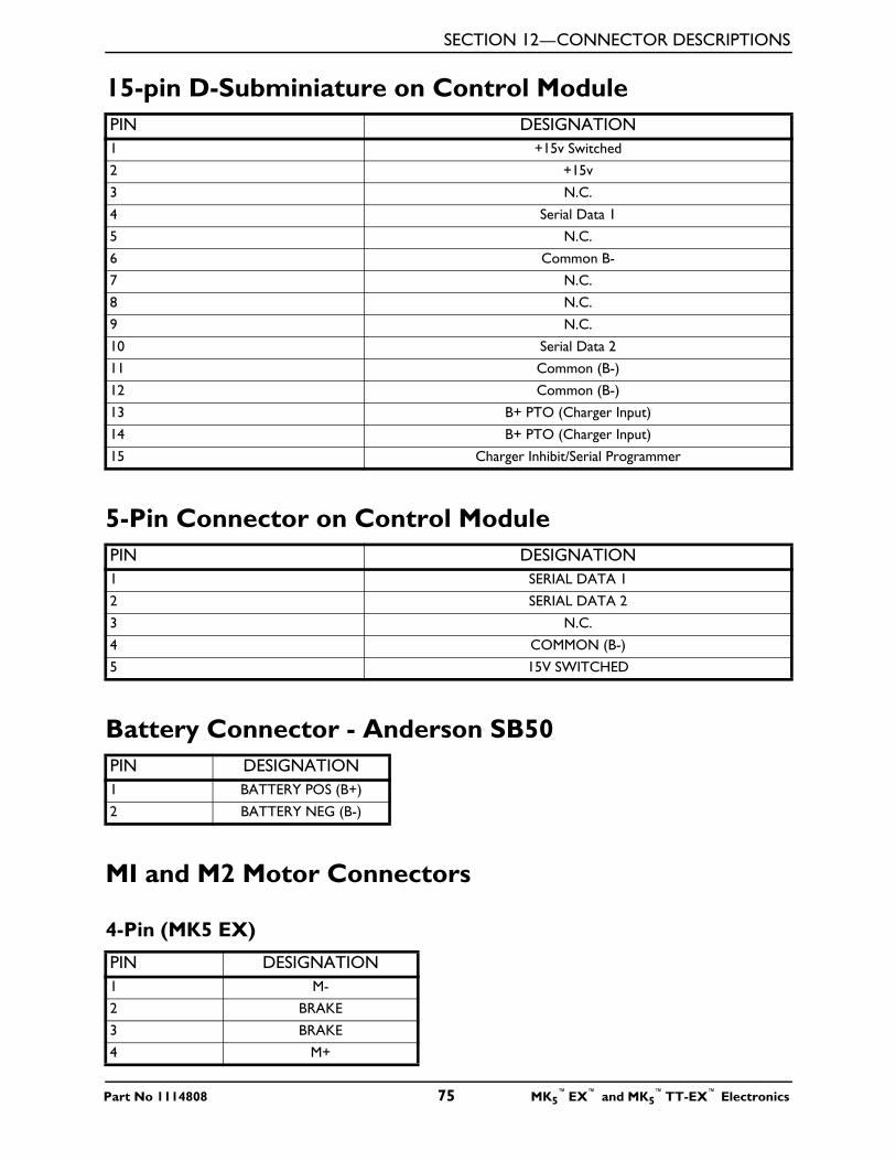
SECTION 12—CONNECTOR DESCRIPTIONS
15-pin D-Subminiature on Control Module
5-Pin Connector on Control Module
Battery Connector - Anderson SB50
MI and M2 Motor Connectors
4-Pin (MK5 EX)
PIN DESIGNATION1 +15v Switched
2 +15v
3 N.C.
4 Serial Data 1
5 N.C.
6 Common B-
7 N.C.
8 N.C.
9 N.C.
10 Serial Data 2
11 Common (B-)
12 Common (B-)
13 B+ PTO (Charger Input)
14 B+ PTO (Charger Input)
15 Charger Inhibit/Serial Programmer
PIN DESIGNATION1 SERIAL DATA 1
2 SERIAL DATA 2
3 N.C.
4 COMMON (B-)
5 15V SWITCHED
PIN DESIGNATION1 BATTERY POS (B+)
2 BATTERY NEG (B-)
PIN DESIGNATION1 M-
2 BRAKE
3 BRAKE
4 M+
Part No 1114808 75 MK5™EX™ and MK5
™TT-EX™ Electronics
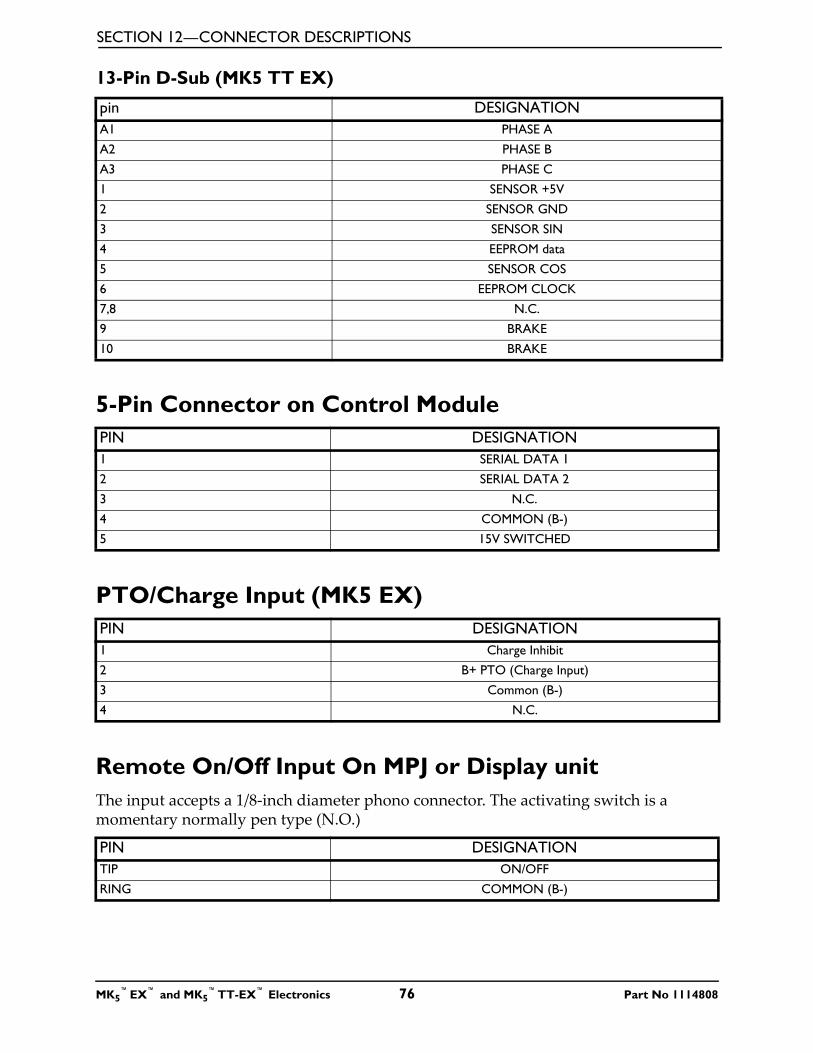
SECTION 12—CONNECTOR DESCRIPTIONS
13-Pin D-Sub (MK5 TT EX)
5-Pin Connector on Control Module
PTO/Charge Input (MK5 EX)
Remote On/Off Input On MPJ or Display unitThe input accepts a 1/8-inch diameter phono connector. The activating switch is a momentary normally pen type (N.O.)
pin DESIGNATIONA1 PHASE A
A2 PHASE B
A3 PHASE C
1 SENSOR +5V
2 SENSOR GND
3 SENSOR SIN
4 EEPROM data
5 SENSOR COS
6 EEPROM CLOCK
7,8 N.C.
9 BRAKE
10 BRAKE
PIN DESIGNATION1 SERIAL DATA 1
2 SERIAL DATA 2
3 N.C.
4 COMMON (B-)
5 15V SWITCHED
PIN DESIGNATION1 Charge Inhibit
2 B+ PTO (Charge Input)
3 Common (B-)
4 N.C.
PIN DESIGNATIONTIP ON/OFF
RING COMMON (B-)
MK5™EX™ and MK5
™TT-EX™ Electronics 76 Part No 1114808
SECTION 13—CURRENT ROLLBACK
SECTION 13—CURRENT ROLLBACK
What Is Current Rollback?Current flows from the batteries, through the controller into the motors. In simple terms, current relates to power (Amps is a measure of current). As speed, load, rolling resistance and terrain angle increases so does the amount of current flowing through the system. Current generates heat. If the heat is excessive for too long, it can lead to component failure. To protect the system, all MK5 controllers have been programmed to limit the amount of current drawn through the system to prevent damage to the circuitry and motors. This feature is called Current Rollback. If the internal temperature of the controller reaches the current rollback setting, the controller will automatically reduce the output which will cause the wheelchair to slow down or stop, depending upon the load and operating terrain. The controller has an internal timer that keeps the operating system at this reduced output until the system has had ample time to cool down. Once it counts down, full power output is restored to the system.
What Increases the Likelihood of Current Rollback?• Weight • Rolling Resistance • Terrain Angle• Speed
Weight
Weight includes the weight of the user, all accessories mounted to the wheelchair and any additional weight accompanying the user such as back packs etc. (It takes more energy to move a wheelchair that is equipped with a power tilt/recline seating system and a ventilator than a wheelchair that is equipped with a standard seat only).
Rolling Resistance
The surface that the wheelchair is operating on makes a difference to how hard the wheelchair has to work. Sand or deep grass offers more rolling resistance than pavement.
Terrain Angle
Inclines require the system to work harder as you fight gravity. Ramps are obvious but the land terrain (slopes, hills) are not as obvious, but play a part in current rollback.
Speed
A system at 100% forward speed requires more power than one programmed at 75%. Combine high-speed settings with factors described above and you increase the likelihood of going into current rollback.
Part No 1114808 77 MK5™EX™ and MK5
™TT-EX™ Electronics
SECTION 13—CURRENT ROLLBACK
How to Solve It?
Electronic Adjustments
1. Load the standard proportional performance or learner indoor program. These have moderate torque levels that should provide adequate power on a well-balanced wheelchair.
2. Be certain the user is selecting an appropriate drive mode for the intended environment. In other words, Learner Indoor programs - unmodified - are not intended to be used over rough outdoor terrain.
3. If the wheelchair feels like it needs more power, then FIRST check the power level setting in EACH drive. Most are set at 80% or lower. Simply increase this parameter and re-save. If more power is still needed, then the torque parameter can be increased. Torque should never need to be maxed out. If it is then there is another problem (i.e. front loading or a drive motor that is not powerful enough for the task).
4. With power level at 100% a very high Torque setting and fast speeds, you could be going into current rollback more quickly because of the amount of current being allowed into the system.
Drive Motors
The standard 4 pole and 2 Pole are rated for loads up to 300 lbs and the heavy duty 4 pole and gearless/brushless motors are rated for loads up to 400 lbs. If the standard 4 pole or 2 pole is not providing enough power once the above has been done, then the user would be a candidate for the heavy duty 4 pole or gearless/brushless motor. Remember heavy duty drives are not just for users over 300 lbs, but also for user's who are very ACTIVE. If the provider knows that the user is a very hard user, then they are better served going to the heavy duty 4 pole or gearless/brushless from the start.
Common MistakesThe most common mistake and aggravation to current rollback is that the user or provider turns the wheelchair off to cool down. The controller has a counter in it that begins to count up when the current reaches a high or extremely high level. Once the wheelchair current is normal again, then it needs to count down. It can only do this with the wheelchair turned ON.If the user claims to be in a state of constant current rollback, then chances are that they are turning their wheelchair off and the counter is remaining high, so that it only takes a little bit of driving to go back into rollback. Good advice is to ask the user to recharge the batteries with the wheelchair electronics turned on. This ensures the "Internal Timer" in the controller resets and the batteries are full.NOTE: Use the charger that is supplied with the Invacare wheelchair.
MK5™EX™ and MK5
™TT-EX™ Electronics 78 Part No 1114808
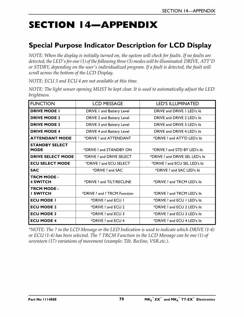
SECTION 14—APPENDIX
Part No 1114808 79 MK5™EX™ and MK5
™TT-EX™ Electronics
SECTION 14—APPENDIX
Special Purpose Indicator Description for LCD DisplayNOTE: When the display is initially turned on, the system will check for faults. If no faults are detected, the LED's for one (1) of the following three (3) modes will be illuminated: DRIVE, ATT'D or STDBY, depending on the user's individualized program. If a fault is detected, the fault will scroll across the bottom of the LCD Display.
NOTE: ECU 3 and ECU 4 are not available at this time.
NOTE: The light sensor opening MUST be kept clear. It is used to automatically adjust the LED brightness.
*NOTE: The ? in the LCD Message or the LED Indication is used to indicate which DRIVE (1-4) or ECU (1-4) has been selected. The ? TRCM Function in the LCD Message can be one (1) of seventeen (17) variations of movement (example: Tilt, Recline, VSR.etc.).
FUNCTION LCD MESSAGE LED'S ILLUMINATED
DRIVE MODE 1 DRIVE 1 and Battery Level DRIVE and DRIVE 1 LED's lit
DRIVE MODE 2 DRIVE 2 and Battery Level DRIVE and DRIVE 2 LED's lit
DRIVE MODE 3 DRIVE 3 and Battery Level DRIVE and DRIVE 3 LED's lit
DRIVE MODE 4 DRIVE 4 and Battery Level DRIVE and DRIVE 4 LED's lit
ATTENDANT MODE *DRIVE ? and ATTENDANT *DRIVE ? and ATT'D LED's lit
STANDBY SELECT MODE *DRIVE ? and STANDBY ON *DRIVE ? and STD BY LED's lit
DRIVE SELECT MODE *DRIVE ? and DRIVE SELECT *DRIVE ? and DRIVE SEL LED's lit
ECU SELECT MODE *DRIVE ? and ECU SELECT *DRIVE ? and ECU SEL LED's lit
SAC *DRIVE ? and SAC *DRIVE ? and SAC LED's lit
TRCM MODE - 4 SWITCH *DRIVE ? and TILT/RECLINE *DRIVE ? and TRCM LED's lit
TRCM MODE - 1 SWITCH *DRIVE ? and ? TRCM Function *DRIVE ? and TRCM LED's lit
ECU MODE 1 *DRIVE ? and ECU 1 *DRIVE ? and ECU 1 LED's lit
ECU MODE 2 *DRIVE ? and ECU 2 *DRIVE ? and ECU 2 LED's lit
ECU MODE 3 *DRIVE ? and ECU 3 *DRIVE ? and ECU 3 LED's lit
ECU MODE 4 *DRIVE ? and ECU 4 *DRIVE ? and ECU 4 LED's lit

LIMITED WARRANTYPLEASE NOTE: THE WARRANTY BELOW HAS BEEN DRAFTED TO COMPLY WITH FEDERAL LAW APPLICABLE TO PRODUCTS MANUFACTURED AFTER JULY 4, 1975.
This warranty is extended only to the original purchaser/user of our products.
This warranty gives you specific legal rights and you may also have other legal rights which vary from state to state.
Invacare warrants the MK5 Controls to be free from defects in materials and workmanship for a period of one (1) year from date of purchase. If within such warranty period any such product shall be proven to be defective, such product shall be repaired or replaced, at Invacare's option. This warranty does not include any labor or shipping charges incurred in replacement part installation or repair of any such product. Invacare's sole obligation and your exclusive remedy under this warranty shall be limited to such repair and/or replacement.
For warranty service, please contact the dealer from whom you purchased your Invacare product. In the event you do not receive satisfactory warranty service, please write directly to Invacare at the address at the bottom of the back cover. Provide dealer’s name, address, date of purchase, indicate nature of the defect and, if the product is serialized, indicate the serial number. Do not return products to our factory without our prior consent.
LIMITATIONS AND EXCLUSIONS: THE FOREGOING WARRANTY SHALL NOT APPLY TO SERIAL NUMBERED PRODUCTS IF THE SERIAL NUMBER HAS BEEN REMOVED OR DEFACED, PRODUCTS SUBJECTED TO NEGLIGENCE, ACCIDENT, IMPROPER OPERATION, MAINTENANCE OR STORAGE, COMMERCIAL OR INSTITUTIONAL USE, PRODUCTS MODIFIED WITHOUT INVACARE'S EXPRESS WRITTEN CONSENT INCLUDING, BUT NOT LIMITED TO, MODIFICATION THROUGH THE USE OF UNAUTHORIZED PARTS OR ATTACHMENTS; PRODUCTS DAMAGED BY REASON OF REPAIRS MADE TO ANY COMPONENT WITHOUT THE SPECIFIC CONSENT OF INVACARE, OR TO A PRODUCT DAMAGED BY CIRCUMSTANCES BEYOND INVACARE'S CONTROL, AND SUCH EVALUATION WILL BE SOLELY DETERMINED BY INVACARE. THE WARRANTY SHALL NOT APPLY TO PROBLEMS ARISING FROM NORMAL WEAR OR FAILURE TO ADHERE TO THESE INSTRUCTIONS.
THE FOREGOING EXPRESS WARRANTY IS EXCLUSIVE AND IN LIEU OF ANY OTHER WARRANTIES WHATSOEVER, WHETHER EXPRESS OR IMPLIED, INCLUDING THE IMPLIED WARRANTIES OF MERCHANTABILITY AND FITNESS FOR A PARTICULAR PURPOSE, AND THE SOLE REMEDY FOR VIOLATIONS OF ANY WARRANTY WHATSOEVER, SHALL BE LIMITED TO REPAIR OR REPLACEMENT OF THE DEFECTIVE PRODUCT PURSUANT TO THE TERMS CONTAINED HEREIN. THE APPLICATION OF ANY IMPLIED WARRANTY WHATSOEVER SHALL NOT EXTEND BEYOND THE DURATION OF THE EXPRESS WARRANTY PROVIDED HEREIN. INVACARE SHALL NOT BE LIABLE FOR ANY CONSEQUENTIAL OR INCIDENTAL DAMAGES WHATSOEVER.THIS WARRANTY SHALL BE EXTENDED TO COMPLY WITH STATE/PROVINCIAL LAWS AND REQUIREMENTS.
Invacare Corporation www.invacare.com
USAOne Invacare WayElyria, Ohio USA44036-2125800-333-6900
Canada570 Matheson Blvd E Unit 8Mississauga OntarioL4Z 4G4 Canada800-668-5324
Invacare is a registered trademark of Invacare Corporation.Yes, you can., MK5, EX, TT-EX, MKIV, DPJ and MPJ are trademarks of Invacare Corporation© 2004 Invacare Corporation
Part No 1114808
Rev D- 11/04