Embed Size (px)
Citation preview

1
MITSUBISHI ELECTRIC PRE-PLUMBED UNVENTED MAINS PRESSURE WATER HEATER WITH FTC5 CONTROL SYSTEM FOR USE WITH THE ECODAN
AIR SOURCE HEAT PUMP RANGE150, 170, 210, 250 and 300 LITRE CAPACITY STANDARD MODELS
210, 250 and 300 LITRE CAPACITY SOLAR MODELS150 and 170 LITRE CAPACITY SLIMLINE MODELS
IMPORTANT: PLEASE READ AND UNDERSTAND THESE INSTRUCTIONS BEFORE COMMENCING INSTALLATION. PLEASE LEAVE THIS MANUAL
WITH THE CUSTOMER FOR FUTURE REFERENCE.
2
CONTENTS
INTRODUCTION ....................................................................................................................................2
GENERAL REQUIREMENTS ................................................................................................................4
INSTALLATION – GENERAL ................................................................................................................14
INSTALLATION - DISCHARGE .............................................................................................................17
INSTALLATION - HEAT PUMP PRIMARY CIRCUIT .............................................................................20
INSTALLATION - SOLAR PRIMARY......................................................................................................29
INSTALLATION - IMMERSION HEATER ELECTRICAL SUPPLY.........................................................30
COMMISSIONING .................................................................................................................................31
MAINTENANCE ....................................................................................................................................33
FAULT FINDING & SERVICING ............................................................................................................35
SPARE PARTS ......................................................................................................................................35
USER INSTRUCTIONS .........................................................................................................................38
ENVIRONMENTAL INFORMATION ......................................................................................................40
TECHNICAL SUPPORT ........................................................................................................................40
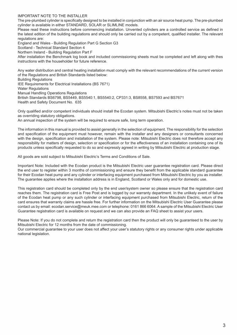
INTRODUCTIONThis range of factory pre-plumbed and wired unvented water heaters specifically designed for use with the Mitsubishi Ecodan Air Source Heat Pump range. The cylinder is manufactured in the UK from top quality materials and meets all the latest relevant safety and constructional standards. The high grade Duplex stainless steel cylinder offers exceptional strength and corrosion resistance. Its performance, control system and insulation levels exceed the latest requirements of Building Regulation Part L.
The unvented water heater can be fed directly from the cold water mains supply to the property without the need for separate feed cisterns or vent pipes. It is supplied fitted with all its necessary inlet and safety controls for compliance with Building Regulations. Also fitted are primary circulating pumps, a DHW circulation pump, primary to DHW plate to plate heat exchanger, 3 way diverter valve, automatic air vent, primary filling loop and pressure gauge, a cylinder thermal cut-out and Mitsubishi Electric FTC5 controller. The pumps, motorised valve and thermal controls are supplied pre-wired. A heating and domestic hot water programmer, The DHW expansion vessel is supplied loose for installation at a convenient position within the property. An electric immersion heater is also fitted to enable the unit to be heated should the heat pump require supplmentary heating or be turned off.
NOTE: If using a sealed heating system, adequate provision for expansion within the primary circuit MUST be provided by fitting a primary circuit expansion vessel. Primary circuit expansion cannot be accommodated within the Air Source Heat Pump cylinder. Ensure a primary circuit expansion relief valve is fitted to the primary circuit.
The safety valves fitted to the Air Source Heat Pump cylinder protect the water heater only. Failure to provide adequate primary system pressure relief when using a sealed heating system will invalidate the Heat Pump warranty. Consult the Heat Pump installation instructions for further advice.
3
IMPORTANT NOTE TO THE INSTALLERThe pre-plumbed cylinder is specifically designed to be installed in conjunction with an air source heat pump. The pre-plumbed cylinder is available in either STANDARD, SOLAR or SLIMLINE models. Please read these instructions before commencing installation. Unvented cylinders are a controlled service as defined in the latest edition of the building regulations and should only be carried out by a competent, qualified installer. The relevant regulations are:England and Wales - Building Regulation Part G Section G3Scotland - Technical Standard Section 4Northern Ireland - Building Regulation Part FAfter installation the Benchmark log book and included commissioning sheets must be completed and left along with thes instructions with the householder for future reference.
Any water distribution and central heating installation must comply with the relevant recommendations of the current version of the Regulations and British Standards listed below:Building RegulationsIEE Requirements for Electrical Installations (BS 7671)Water Regulations Manual Handling Operations RegulationsBritish Standards BS6798, BS5449, BS5540:1, BS5540:2, CP331:3, BS8558, BS7593 and BS7671Health and Safety Document No. 635
Only qualified and/or competent individuals should install the Ecodan system. Mitsubishi Electric’s notes must not be taken as overriding statutory obligations.An annual inspection of the system will be required to ensure safe, long term operation.
The information in this manual is provided to assist generally in the selection of equipment. The responsibility for the selection and specification of the equipment must however, remain with the installer and any designers or consultants concerned with the design, specification and installation of the system. Please note: Mitsubishi Electric does not therefore accept any responsibility for matters of design, selection or specification or for the effectiveness of an installation containing one of its products unless specifically requested to do so and expressly agreed in writing by Mitsubishi Electric at production stage.
All goods are sold subject to Mitsubishi Electric’s Terms and Conditions of Sale.
Important Note: Included with the Ecodan product is the Mitsubishi Electric user guarantee registration card. Please direct the end user to register within 3 months of commissioning and ensure they benefit from the applicable standard guarantee for their Ecodan heat pump and any cylinder or interfacing equipment purchased from Mitsubishi Electric by you as installer. The guarantee applies where the installation address is in England, Scotland or Wales only and for domestic use.
This registration card should be completed only by the end user/system owner so please ensure that the registration card reaches them. The registration card is Free Post and is logged by our warranty department. In the unlikely event of failure of the Ecodan heat pump or any such cylinder or interfacing equipment purchased from Mitsubishi Electric, return of the card ensures that warranty claims are hassle free. For further information on the Mitsubishi Electric User Guarantee please contact us by email: [email protected] or telephone: 0161 866 6064. A sample of the Mitsubishi Electric User Guarantee registration card is available on request and we can also provide an FAQ sheet to assist your users.
Please Note: If you do not complete and return the registration card then the product will only be guaranteed to the user by Mitsubishi Electric for 12 months from the date of commissioning.Our commercial guarantee to your user does not affect your user’s statutory rights or any consumer rights under applicable national legislation.
4
GENERAL REQUIREMENTSIMPORTANT: THIS APPLIANCE CAN BE USED BY CHILDREN AGED FROM 8 YEARS AND ABOVE AND PERSONS WITH REDUCED PHYSICAL SENSORY OR MENTAL CAPABILITIES OR LACK OF EXPERIENCE AND KNOWLEDGE IF THEY HAVE BEEN GIVEN SUPERVISORY OR INSTRUCTION CONCERNING USE OF THE APPLIANCE IN A SAFE WAY AND UNDERSTAND THE HAZARDS INVOLVED. CHILDREN SHALL NOT PLAY WITH THE APPLIANCE. CLEANING AND USER MAINTENANCE SHALL NOT BE MADE BY CHILDREN WITHOUT SUPERVISION.
WARNING: Do not switch on if there is a possibility that the water in the heater is frozen.
COMPONENT CHECK LIST
Before commencing installation check that all the components for your Air Source Heat Pump cylinder are contained in the package. The following components are supplied with your unit :• Factory fitted Temperature and Pressure Relief Valve (set at 90°C/10bar) Immersion heater and over-temperature cut-out Expansion core unit (comprises expansion valve and check valve) Tundish Primary circulating pump (Low Loss Header to Heat Pump return) Primary circulating pump (Low Loss Header to Heating circuit) DHW circulating pump 3 Way motorised diverter valve Primary to DHW plate to plate heat exchanger Fernox TF1 Compact Magnetic filter Automatic bypass valve (supplied loose) Primary circuit filling loop Primary circuit pressure gauge Automatic air vent FTC5 Controller Solar over-temperature thermal cutout (Solar models only)• Supplied loose Mitsubishi Electric CH/DHW Main Controller Potable water expansion vessel Cold water combination valve (comprises pressure reducing valve, strainer, check valve) Automatic differential pressure bypass valve
STORAGE AND HANDLING
Prior to installation the Pre-plumbed cylinder unit must be stored vertically upright on a secure, level surface in a dry, frost free environment. Take note of the weight of the product and follow safe working practices when lifting, moving or manipulating into position. DO NOT lift by the pre-plumbed pipework manifold.
SITING THE UNIT
The Pre-plumbed cylinder unit must be vertically floor mounted. It can be placed anywhere convenient provided the discharge pipe(s) from its safety valves can be correctly installed and all pre-fitted ancillary parts can be accessed for servicing and/or maintenance. Areas that are subject to freezing must be avoided. Ensure that the floor is of sufficient strength to support the “full” weight of the unit (Table 1, page 5). Pipe runs should be kept as short as possible for maximum economy.
Additional automatic air vents (AAV) (not supplied) may be required at high points in the primary system where pipework is located above the level of the cylinder.
WATER SUPPLY
Bear in mind that the water supply to the property will be supplying both the hot and cold water requirements simultaneously. It is recommended that the maximum water demand is assessed and the water supply checked to ensure this demand can be satisfactorily met.
NOTE: A high water pressure will not always guarantee high flow rates.
Wherever possible the cylinder supply pipe should be 22mm. We suggest the minimum supply requirements should be 1.5 bar pressure and 20 litres per minute flow rate. However, at these values outlet flow rates may be poor if several outlets are used simultaneously. The higher the available pressure and flow rate the better the system performance.
The cylinder has an operating pressure of 3.5 bar which is controlled by the cold water combination valve assembly. The cold water combination valve assembly can be connected to a maximum inlet pressure of 16 bar.
5
OUTLET/TERMINAL FITTINGS (TAPS, ETC.)
The Pre-plumbed cylinder can be used in conjunction with most types of terminal fittings, plumbing fittings and pipework. However, the rated pressures of any fittings selected should be checked for compatibility before installation.
NOTE: Accessories, plumbing fittings and pipework should have a rated operating pressure of at least 8 bar.Outlets situated higher than the cylinder will give outlet pressures lower than that at the unit, a 10m height difference will result in a 1 bar pressure reduction at the outlet fitting.
LIMITATIONS
The Pre-plumbed cylinder should not be used in association with any of the following:• Solid fuel boilers or any other boiler in which the energy input is not under effective thermostatic control, unless additional
and appropriate safety measures are installed.• Ascending spray type bidets or any other class 1 back syphonage risk require that a type A air gap be employed.• Steam heating plants unless additional and appropriate safety devices are installed.• Situations where maintenance is likely to be neglected or safety devices tampered with.• Water supplies that have either inadequate pressure or where the supply may be intermittent.• Situations where it is not possible to safely pipe away any discharge from the safety valves.• In areas where the water consistently contains a high proportion of solids, e.g. suspended matter that could block the
strainer unless adequate filtration can be ensured.
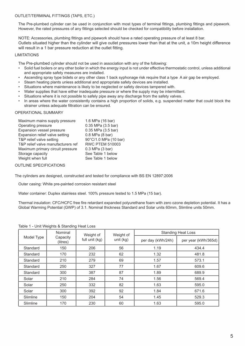
OPERATIONAL SUMMARY
Maximum mains supply pressure 1.6 MPa (16 bar)Operating pressure 0.35 MPa (3.5 bar)Expansion vessel pressure 0.35 MPa (3.5 bar)Expansion relief valve setting 0.8 MPa (8 bar)T&P relief valve setting 90°C/1.0 MPa (10 bar) T&P relief valve manufacturers ref RWC PTEM 510003Maximum primary circuit pressure 0.3 MPa (3 bar)Storage capacity See Table 1 belowWeight when full See Table 1 below
OUTLINE SPECIFICATIONS
The cylinders are designed, constructed and tested for compliance with BS EN 12897:2006
Outer casing: White pre-painted corrosion resistant steel
Water container: Duplex stainless steel. 100% pressure tested to 1.5 MPa (15 bar).
Thermal insulation: CFC/HCFC free fire retardant expanded polyurethane foam with zero ozone depletion potential. It has a Global Warming Potential (GWP) of 3.1. Nominal thickness Standard and Solar units 60mm, Slimline units 50mm.
Table 1 - Unit Weights & Standing Heat Loss
Model TypeNominal Capacity
(litres)
Weight of full unit (kg)
Weight of unit (kg)
Standing Heat Loss
per day (kWh/24h) per year (kWh/365d)
Standard 150 206 56 1.19 434.4Standard 170 232 62 1.32 481.8Standard 210 279 69 1.57 573.1Standard 250 327 77 1.67 609.6Standard 300 387 87 1.89 689.9Solar 210 284 74 1.56 569.4Solar 250 332 82 1.63 595.0Solar 300 392 92 1.84 671.6Slimline 150 204 54 1.45 529.3Slimline 170 230 60 1.63 595.0
6
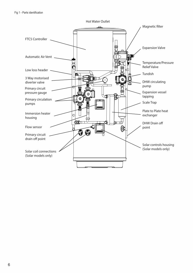
Fig 1 - Parts identification
Temperature/PressureRelief Valve
Expansion Valve
Tundish
DHW circulatingpump
Scale Trap
DHW Drain o�point
Plate to Plate heatexchanger
Solar controls housing(Solar models only)
Solar coil connections(Solar models only)
Flow sensor
Primary circulationpumps
3 Way motoriseddiverter valve
Low loss header
Automatic Air Vent
FTC5 Controller
Hot Water OutletMagnetic �lter
Immersion heaterhousing
Primary circuitpressure gauge
Primary circuit drain o� point
Expansion vesseltapping
7
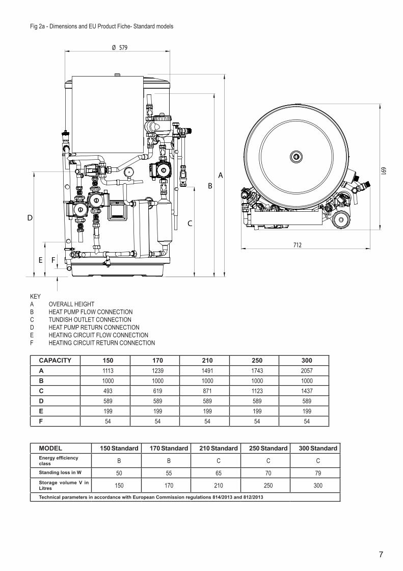
Ø 579
691
712
AB
CD
E F
KEYA OVERALL HEIGHTB HEAT PUMP FLOW CONNECTIONC TUNDISH OUTLET CONNECTIOND HEAT PUMP RETURN CONNECTIONE HEATING CIRCUIT FLOW CONNECTIONF HEATING CIRCUIT RETURN CONNECTION
CAPACITY 150 170 210 250 300A 1113 1239 1491 1743 2057B 1000 1000 1000 1000 1000C 493 619 871 1123 1437D 589 589 589 589 589E 199 199 199 199 199F 54 54 54 54 54
Fig 2a - Dimensions and EU Product Fiche- Standard models
MODEL 150 Standard 170 Standard 210 Standard 250 Standard 300 StandardEnergy efficiency class B B C C CStanding loss in W 50 55 65 70 79Storage volume V in Litres 150 170 210 250 300Technical parameters in accordance with European Commission regulations 814/2013 and 812/2013

8
678
694
A
B
CD
E
F G
579
KEYA OVERALL HEIGHTB HEAT PUMP FLOW CONNECTIONC TUNDISH OUTLET CONNECTIOND HEAT PUMP RETURN CONNECTIONE HEATING CIRCUIT FLOW CONNECTIONF HEATING CIRCUIT RETURN CONNECTIONG SOLAR COIL CONNECTIONS
CAPACITY 210 250 300A 1497 1749 2064B 1350 1350 1350C 877 1129 1444D 939 939 939E 549 549 549F 404 404 404G 373 373 373
Fig 2b - Dimensions and EU Product Fiche - Solar models
Solar coil specification:Surface Area: 1.1m2
Coil volume: 5.8 litresPressure drop: 3.6 kPa (0.036 bar)Output rating: 30kW at 80oC flow temperature, 15 litres/minute flow rateConnections: 22mm compression / 3/4” BSP male
MODEL 210 Solar 250 Solar 300 SolarEnergy efficiency class C C CStanding loss in W 65 68 77Storage volume V in Litres 210 250 300Technical parameters in accordance with European Commission regulations 814/2013 and 812/2013

9
Ø 491
600
595
A
B
C
D
E
F
KEYA OVERALL HEIGHTB HEAT PUMP FLOW CONNECTIONC TUNDISH OUTLET CONNECTIOND HEAT PUMP RETURN CONNECTIONE HEATING CIRCUIT FLOW CONNECTIONF HEATING CIRCUIT RETURN CONNECTION
CAPACITY 150 170A 1495 1669B 1051 1051C 944 1118D 641 939E 250 549F 105 404
Fig 2c - Dimensions and EU Product Fiche- Slimline models
MODEL 150 Slimline 170 SlimlineEnergy efficiency class C CStanding loss in W 60 68Storage volume V in Litres 150 170Technical parameters in accordance with European Commission regulations 814/2013 and 812/2013
10
150
170
210
250
300
Prim
ary flo
w ra
te W
50-W
85-W
112-
HW14
0Pu
mp
Conn
ectio
n si
ze H
eatin
g/DH
A (m
m)
DHW
Exp
ansi
on v
esse
l (lit
res)
1218
1824
24Ch
arge
pre
ssur
e (M
Pa (b
ar))
Cont
rol t
herm
isto
r (o C)
Pres
sue
Relie
f Val
ve (M
Pa (b
ar))
Cont
rol t
herm
isto
r (o C)
Ove
r-te
mpe
ratu
re cu
t-ou
t (o C)
Tem
p/Pr
essu
re R
elie
f Val
ve (o C/
MPa
(bar
))Ex
pans
ion
valv
e (M
Pa (b
ar))
Wid
th
Dept
h He
ight
Vess
el
Type
Nom
inal
thic
knes
s (m
m)
Stan
ding
hea
t los
s (kW
h/24
h)O
zone
Dep
l etio
n Po
tenti
alGl
obal
War
min
g Po
tenti
alEl
ectr
ical
supp
lyPh
ase
Fuse
ratin
g - M
CB S
ize
(A)
Elec
tric
al su
pply
Phas
eRa
ting
(kW
at 2
40V)
Max
curr
ent (
A)Fu
se ra
ting
- MCB
Siz
e (A
)
PAR-
WT5
0-E
cont
rolle
r & P
AR-W
R51-
E re
ceiv
er
zero 3.1
220
- 240
V ~
, 50
Hzsi
ngle
1022
0 - 2
40 V
~ ,
50Hz
sing
le3 13 16
DHW
and
1 h
eatin
g zo
ne
80 +
/- 5
90 /
1.0
(10.
0)0.
8 (8
.0)
Dupl
ex st
ainl
ess s
teel
Expa
nded
pol
yure
than
e (P
U)60
Mec
hani
cal z
ones
Opti
onal
wire
les r
oom
ther
mos
tat a
nd w
irele
ss re
ceiv
er
STAN
DARD
0.35
(3.5
)
22
Prim
ary
- 2 x
Gru
ndfo
s UPS
2 25
-60,
DHW
Gru
ndfo
s UP
SO 1
5-60
CIL
2
14.
3 - 2
5.8
- 32.
1 - 4
0.1
l/min
1-80
0.3
(3.0
)40
- 70
Dim
ensi
ons (
mm
)
Wei
ght e
mpt
y/fu
ll (k
g)M
ater
ials
Insu
latio
n
Elec
tric
al d
ata
Cont
rol B
oard
(o
ption
ally
pow
ered
by
out
door
uni
t)Im
mer
sion
hea
ter
UNIT
Nom
inal
hot
wat
er ca
paci
ty (l
itres
)W
ater
Safe
ty d
evic
esPr
imar
y ci
rcui
t
DHW
circ
uit
712
712
712
712
712
691
691
691
691
691
1113
1239
1491
1743
2057
1.19
1.32
1.57
1.67
1.89
56 /
206
62 /
232
69 /
279
77 /
327
87 /
387
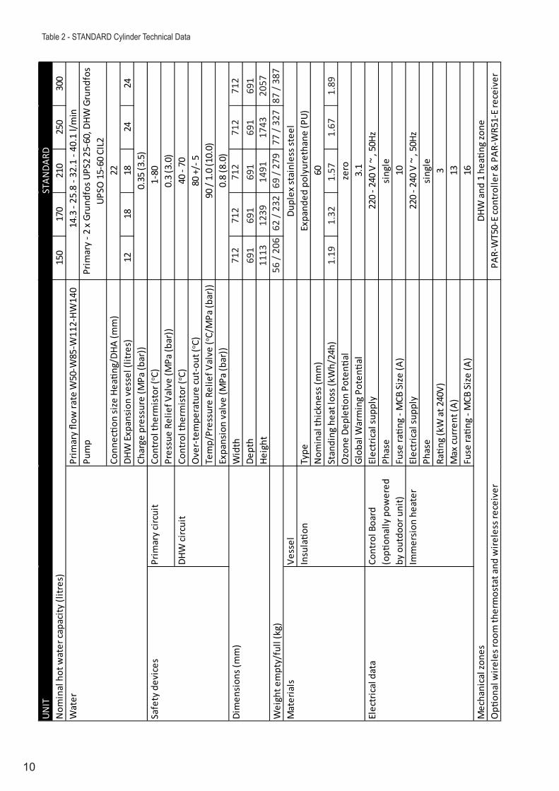
Table 2 - STANDARD Cylinder Technical Data
11
210
250
300
Prim
ary flo
w ra
te W
50-W
85-W
112-
HW14
0Pu
mp
Conn
ectio
n si
ze H
eatin
g/DH
A (m
m)
DHW
Exp
ansi
on v
esse
l (lit
res)
1824
24Ch
arge
pre
ssur
e (M
Pa (b
ar))
Sola
r coi
l hea
ting
surf
ace
(m2)
Cont
rol t
herm
isto
r (o C)
Pres
sue
Relie
f Val
ve (M
Pa (b
ar))
Cont
rol t
herm
isto
r (o C)
Ove
r-te
mpe
ratu
re cu
t-ou
t (o C)
Tem
p/Pr
essu
re R
elie
f Val
ve (o C/
MPa
(bar
))Ex
pans
ion
valv
e (M
Pa (b
ar))
Wid
th
Dept
h He
ight
Vess
elSo
lar h
eatin
g co
ilTy
peN
omin
al th
ickn
ess (
mm
)St
andi
ng h
eat l
oss (
kWh/
24h)
Ozo
ne D
epletio
n Po
tenti
alGl
obal
War
min
g Po
tenti
alEl
ectr
ical
supp
lyPh
ase
Fuse
ratin
g - M
CB S
ize
(A)
Elec
tric
al su
pply
Phas
eRa
ting
(kW
at 2
40V)
Max
curr
ent (
A)Fu
se ra
ting
- MCB
Siz
e (A
)
Imm
ersi
on h
eate
r
Cylin
der
UNIT
Nom
inal
hot
wat
er ca
paci
ty (l
itres
)
Safe
ty d
evic
esPr
imar
y ci
rcui
t
DHW
circ
uit
Wat
er
Mec
hani
cal z
ones
Opti
onal
wire
les r
oom
ther
mos
tat a
nd w
irele
ss re
ceiv
er
SOLA
R
0.35
(3.5
)
22
Prim
ary
- 2 x
Gru
ndfo
s UPS
2 15
-60,
DHW
Gru
ndfo
s UP
SO 1
5-60
CIL
2
14.3
- 25
.8 -
32.1
- 40
.1 l/
min
1 - 8
00.
3 (3
.0)
40 -
70
Dim
ensi
ons (
mm
)
Wei
ght e
mpt
y/fu
ll (k
g)M
ater
ials
Insu
latio
n
Elec
tric
al d
ata
Cont
rol B
oard
(opti
onal
ly p
ower
ed b
y ou
tdoo
r uni
t
DHW
and
1 h
eatin
g zo
nePA
R-W
T50-
E co
ntro
ller &
PAR
-WR5
1-E
rece
iver
zero 3.1
220
- 240
V ~
, 50
Hzsi
ngle
1022
0 - 2
40 V
~ ,
50Hz
1.1
sing
le3 13 16
80 +
/- 5
90 /
1.0
(10.
0)0.
8 (8
.0)
Dupl
ex st
ainl
ess s
teel
Expa
nded
pol
yure
than
e (P
U)60
316L
stai
nles
s ste
el
678
678
678
694
694
694
1497
1749
2064
1.56
1.63
1.84
82 /
332
92 /
392
74 /
284
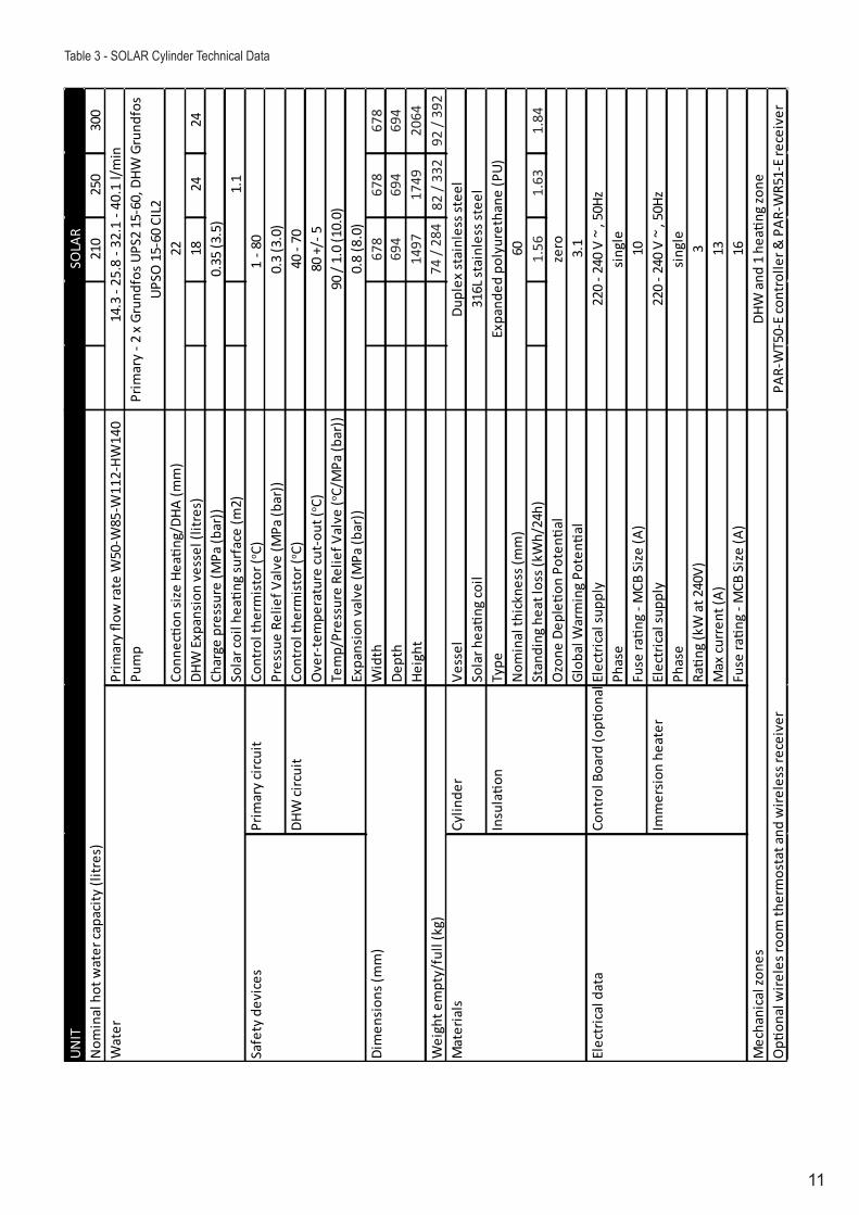
Table 3 - SOLAR Cylinder Technical Data
12
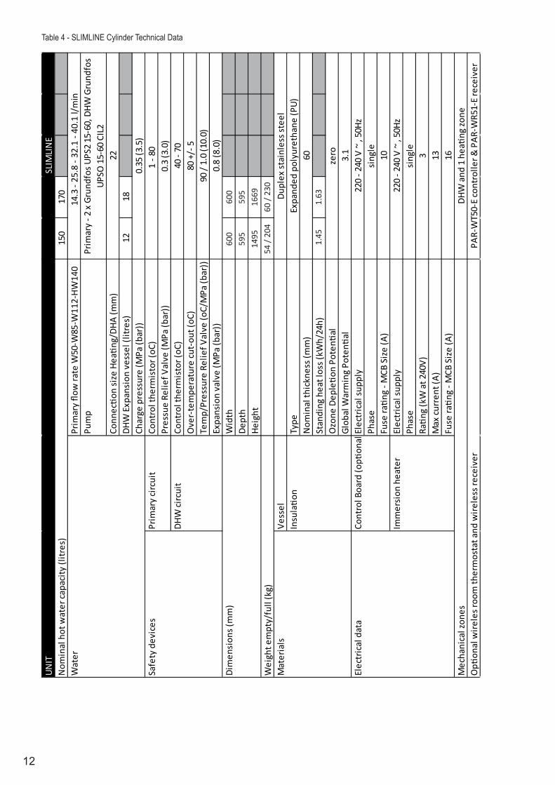
150
170
Prim
ary flo
w ra
te W
50-W
85-W
112-
HW14
0Pu
mp
Conn
ectio
n si
ze H
eatin
g/DH
A (m
m)
DHW
Exp
ansi
on v
esse
l (lit
res)
1218
Char
ge p
ress
ure
(MPa
(bar
))Co
ntro
l the
rmis
tor (
oC)
Pres
sue
Relie
f Val
ve (M
Pa (b
ar))
Cont
rol t
herm
isto
r (oC
)O
ver-
tem
pera
ture
cut-
out (
oC)
Tem
p/Pr
essu
re R
elie
f Val
ve (o
C/M
Pa (b
ar))
Expa
nsio
n va
lve
(MPa
(bar
))W
idth
De
pth
Heig
ht
Vess
el
Type
Nom
inal
thic
knes
s (m
m)
Stan
ding
hea
t los
s (kW
h/24
h)O
zone
Dep
letio
n Po
tenti
a lGl
obal
War
min
g Po
tenti
alEl
ectr
ical
supp
lyPh
ase
Fuse
ratin
g - M
CB S
ize
(A)
Elec
tric
al su
pply
Phas
eRa
ting
(kW
at 2
40V)
Max
curr
ent (
A)Fu
se ra
ting
- MCB
Siz
e (A
)
PAR-
WT5
0-E
cont
rolle
r & P
AR-W
R51-
E re
ceiv
er
zero 3.1
220
- 240
V ~
, 50
Hzsi
ngle
1022
0 - 2
40 V
~ ,
50Hz
sing
le3 13 16
DHW
and
1 h
eatin
g zo
ne
80 +
/- 5
90 /
1.0
(10.
0)0.
8 (8
.0)
Dupl
ex st
ainl
ess s
teel
Expa
nded
pol
yure
than
e (P
U)60
Mec
hani
cal z
ones
Opti
onal
wire
les r
oom
ther
mos
tat a
nd w
irele
ss re
ceiv
er
SLIM
LIN
E
0.35
(3.5
)
22
Prim
ary
- 2 x
Gru
ndfo
s UPS
2 15
-60,
DHW
Gru
ndfo
s UP
SO 1
5-60
CIL
2
14.3
- 25
.8 -
32.1
- 40
.1 l/
min
1 - 8
00.
3 (3
.0)
40 -
70
Dim
ensi
ons (
mm
)
Wei
ght e
mpt
y/fu
ll (k
g)M
ater
ials
Insu
latio
n
Elec
tric
al d
ata
Cont
rol B
oard
(opti
onal
ly p
ower
ed b
y ou
tdoo
r uni
t
Imm
ersi
on h
eate
r
UNIT
Nom
inal
hot
wat
er ca
paci
ty (l
itres
)W
ater
Safe
ty d
evic
esPr
imar
y ci
rcui
t
DHW
circ
uit
600
600
595
595
1495
1669
54 /
204
60 /
230
1.45
1.63
Table 4 - SLIMLINE Cylinder Technical Data
13
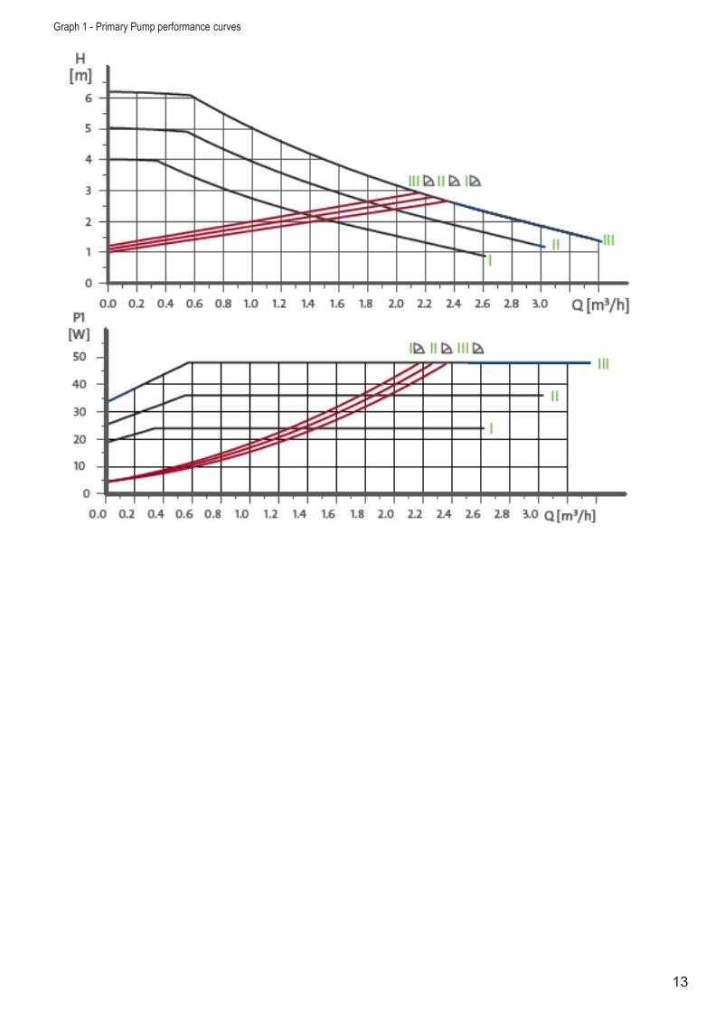
Graph 1 - Primary Pump performance curves
14
INSTALLATION – GENERAL
PIPE FITTINGS
The connection points to the heating system are in 22mm copper pipe. The use of appropriately sized COMPRESSION FITTINGS is recommended when connecting to the pipes. Solder fittings can be used, but extreme care must be taken to ensure any anciallry components in close proximity are not damaged by heat. Push fit type fittings can be used for connection to the copper pipes.
The inlet connection to the cold water combination valve is 22mm compression. The cylinder outlet fitting is suitable for connection to 22mm o/dia pipe (compression nut and olive supplied). The outlet is also threaded 3/4” BSP male parallel should threaded pipe connections be preferred.
COLD FEED
A 22mm cold water supply is recommended, however, if a 15mm (1/2”) supply exists which provides sufficient flow, this may be used. More flow noise may be experienced from small bore pipes due to the increased water velocity through them.
A stopcock or servicing valve should be incorporated into the cold water supply to enable the cylinder and its associated controls to be isolated and serviced.
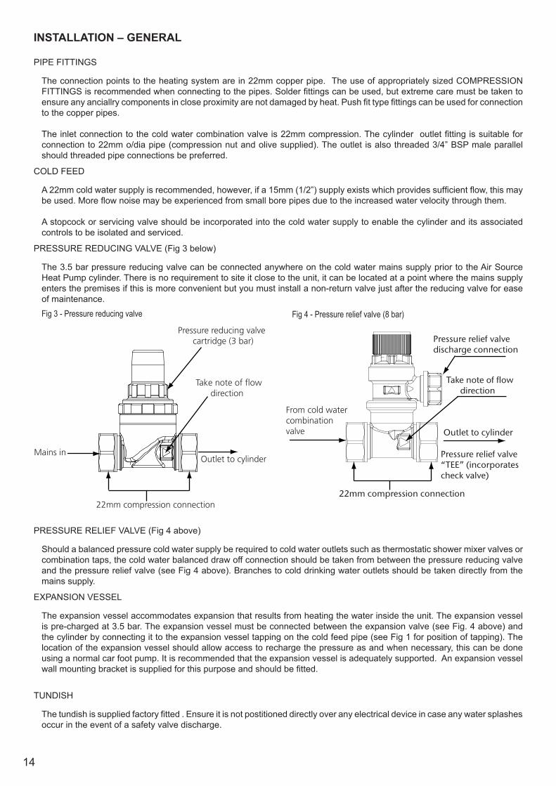
PRESSURE REDUCING VALVE (Fig 3 below)
The 3.5 bar pressure reducing valve can be connected anywhere on the cold water mains supply prior to the Air Source Heat Pump cylinder. There is no requirement to site it close to the unit, it can be located at a point where the mains supply enters the premises if this is more convenient but you must install a non-return valve just after the reducing valve for ease of maintenance.Fig 3 - Pressure reducing valve Fig 4 - Pressure relief valve (8 bar)
PRESSURE RELIEF VALVE (Fig 4 above)
Should a balanced pressure cold water supply be required to cold water outlets such as thermostatic shower mixer valves or combination taps, the cold water balanced draw off connection should be taken from between the pressure reducing valve and the pressure relief valve (see Fig 4 above). Branches to cold drinking water outlets should be taken directly from the mains supply.
EXPANSION VESSEL
The expansion vessel accommodates expansion that results from heating the water inside the unit. The expansion vessel is pre-charged at 3.5 bar. The expansion vessel must be connected between the expansion valve (see Fig. 4 above) and the cylinder by connecting it to the expansion vessel tapping on the cold feed pipe (see Fig 1 for position of tapping). The location of the expansion vessel should allow access to recharge the pressure as and when necessary, this can be done using a normal car foot pump. It is recommended that the expansion vessel is adequately supported. An expansion vessel wall mounting bracket is supplied for this purpose and should be fitted.
TUNDISH
The tundish is supplied factory fitted . Ensure it is not postitioned directly over any electrical device in case any water splashes occur in the event of a safety valve discharge.
Outlet to cylinderMains in
22mm compression connection
Take note of flow direction
Pressure reducing valve cartridge (3 bar)
22mm compression connection
Outlet to cylinder
From cold watercombination valve
Take note of �ow direction
Pressure relief valvedischarge connection
Pressure relief valve“TEE” (incorporatescheck valve)
15
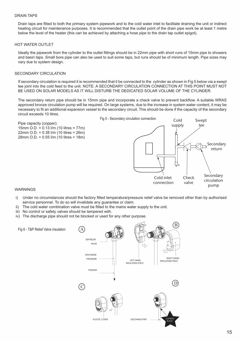
DRAIN TAPS
Drain taps are fitted to both the primary system pipework and to the cold water inlet to facilitate draining the unit or indirect heating circuit for maintenance purposes. It is recommended that the outlet point of the drain pipe work be at least 1 metre below the level of the heater (this can be achieved by attaching a hose pipe to the drain tap outlet spigot).
HOT WATER OUTLET
Ideally the pipework from the cylinder to the outlet fittings should be in 22mm pipe with short runs of 15mm pipe to showers and basin taps. Small bore pipe can also be used to suit some taps, but runs should be of minimum length. Pipe sizes may vary due to system design.
SECONDARY CIRCULATION
If secondary circulation is required it is recommended that it be connected to the cylinder as shown in Fig 5 below via a swept tee joint into the cold feed to the unit. NOTE: A SECONDARY CIRCULATION CONNECTION AT THIS POINT MUST NOT BE USED ON SOLAR MODELS AS IT WILL DISTURB THE DEDICATED SOLAR VOLUME OF THE CYLINDER.
The secondary return pipe should be in 15mm pipe and incorporate a check valve to prevent backflow. A suitable WRAS approved bronze circulation pump will be required. On large systems, due to the increase in system water content, it may be necessary to fit an additional expansion vessel to the secondary circuit. This should be done if the capacity of the secondary circuit exceeds 10 litres.
Pipe capacity (copper):15mm O.D. = 0.13 l/m (10 litres = 77m)22mm O.D. = 0.38 l/m (10 litres = 26m)28mm O.D. = 0.55 l/m (10 litres = 18m)
WARNINGS
i) Under no circumstances should the factory fitted temperature/pressure relief valve be removed other than by authorised service personnel. To do so will invalidate any guarantee or claim.
ii) The cold water combination valve must be fitted to the mains water supply to the unit.iii) No control or safety valves should be tampered with.iv) The discharge pipe should not be blocked or used for any other purpose.
Cold inlet connection
Checkvalve
Secondarycirculation
pump
Swept tee
Coldsupply
Secondaryreturn
Fig 5 - Secondary circulation connection
AB
CD
T&P RELIEF
VALVE
DISCHARGE
PIPEWORK
TUNDISH
LEFT HANDINSULATING PIECE
PLASTIC COVER DISCHARGE PIPE
RIGHT HANDINSULATING PIECE
CLIP INTOPLACE !
Fig 6 - T&P Relief Valve insulation

16
Fig 7 - Schematic installation diagramB
alan
ced
cold
wat
er
draw
-off
MC
WS
to K
itche
n(u
nbal
ance
d co
ldm
ains
sup
ply)
Inco
min
g C
old
Wat
er M
ain
Dis
char
ge p
ipe
to a
tmos
pher
e(s
ee p
age
12 “I
nsta
llatio
n - D
isch
arge
”)
HW
S s
uppl
yB
alan
ced
HW
S a
ndM
CW
S to
bat
hroo
ms,
show
ers,
clo
akro
oms,
etc
Pa
To s
pace
hea
ting
circ
uit Z
one
1
1
23
4
5
6
7
8
9
10
11
1213
14
151617
1819
20
21
22
23
26
2524
27
Par
ts s
how
n w
ithin
das
hed
line
are
supp
lied
KEY
1 He
at Pu
mp
13
Scale
Trap
25
Prim
ary c
ircuit
draw
off p
oint
2
Cylin
der
14
DH
W C
ircula
ting P
ump
26
Autom
atic A
ir Ven
t3
FTC5
Con
trolle
r
15
Flo
w Se
nsor
27
Diffe
renti
al Pr
essu
re B
ypas
s Valv
e4
Imme
rsion
heate
r
16
Pr
imar
y Pum
p
(su
pplie
d loo
se5
3.5 ba
r Pre
ssur
e red
ucing
Valv
e inc
orpo
ratin
g
17
Prim
ary E
xpan
sion V
esse
l
Stra
iner a
nd C
heck
Valv
e (su
pplie
d loo
se)
18
Pr
imar
y Pre
ssur
e Reli
ef va
lve6
8 bar
Exp
ansio
n Valv
e and
Che
ck V
alve
19
Magn
etic F
ilter
7 DH
W E
xpan
sion V
esse
l (sup
plied
loos
e)
20
Pr
imar
y Sys
tem P
ress
ure G
auge
8 St
op C
ock
21
3 Way
Moto
rised
Dive
rter V
alve
9 Ma
ins S
top C
ock
22
Low
Loss
Hea
der in
corp
orati
ng po
rts fo
r10
Tu
ndish
2n
d hea
ting z
one a
nd al
terna
tive h
eat s
ource
11
Temp
eratu
re/P
ress
ure r
elief
Valve
23
Pr
imar
y Pum
p12
Pl
ate to
PLa
te He
at Ex
chan
ger
24
DHW
Dra
inoff p
oint
17
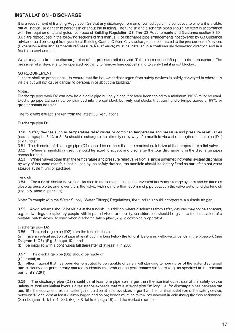
INSTALLATION - DISCHARGE It is a requirement of Building Regulation G3 that any discharge from an unvented system is conveyed to where it is visible, but will not cause danger to persons in or about the building. The tundish and discharge pipes should be fitted in accordance with the requirements and guidance notes of Building Regulation G3. The G3 Requirements and Guidance section 3.50 - 3.63 are reproduced in the following sections of this manual. For discharge pipe arrangements not covered by G3 Guidance advice should be sought from your local Building Control Officer. Any discharge pipe connected to the pressure relief devices (Expansion Valve and Temperature/Pressure Relief Valve) must be installed in a continuously downward direction and in a frost free environment.
Water may drip from the discharge pipe of the pressure relief device. This pipe must be left open to the atmosphere. The pressure relief device is to be operated regularly to remove lime deposits and to verify that it is not blocked.
G3 REQUIREMENT“...there shall be precautions...to ensure that the hot water discharged from safety devices is safely conveyed to where it is visible but will not cause danger to persons in or about the building.”
Notes: Discharge pipe-work D2 can now be a plastic pipe but only pipes that have been tested to a minimum 110°C must be used.Discharge pipe D2 can now be plumbed into the soil stack but only soil stacks that can handle temperatures of 99°C or greater should be used.
The following extract is taken from the latest G3 Regulations
Discharge pipe D1
3.50 Safety devices such as temperature relief valves or combined temperature and pressure and pressure relief valves (see paragraphs 3.13 or 3.18) should discharge either directly or by way of a manifold via a short length of metal pipe (D1) to a tundish.3.51 The diameter of discharge pipe (D1) should be not less than the nominal outlet size of the temperature relief valve.3.52 Where a manifold is used it should be sized to accept and discharge the total discharge form the discharge pipes connected to it.3.53 Where valves other than the temperature and pressure relief valve from a single unvented hot water system discharge by way of the same manifold that is used by the safety devices, the manifold should be factory fitted as part of the hot water storage system unit or package.
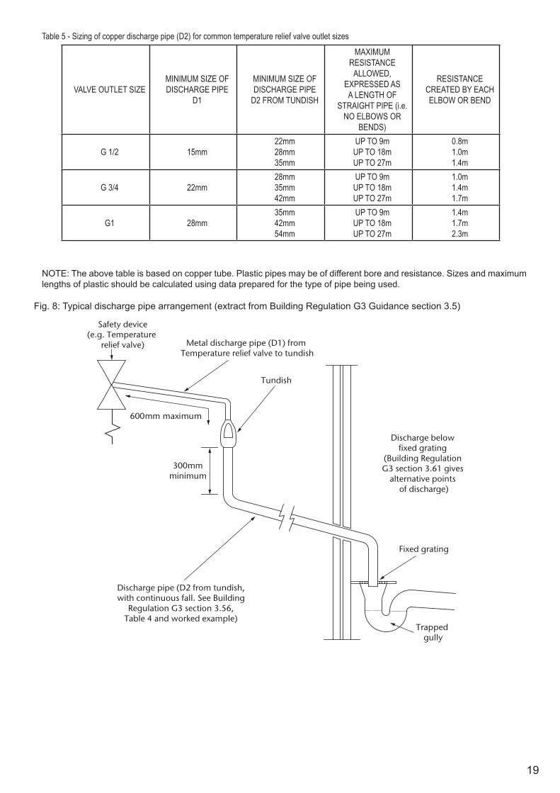
Tundish3.54 The tundish should be vertical, located in the same space as the unvented hot water storage system and be fitted as close as possible to, and lower than, the valve, with no more than 600mm of pipe between the valve outlet and the tundish (Fig. 8 & Table 5, page 19).
Note: To comply with the Water Supply (Water Fittings) Regulations, the tundish should incorporate a suitable air gap.
3.55 Any discharge should be visible at the tundish. In addition, where discharges from safety devices may not be apparent, e.g. in dwellings occupied by people with impaired vision or mobility, consideration should be given to the installation of a suitable safety device to warn when discharge takes place, e.g. electronically operated.
Discharge pipe D23.56 The discharge pipe (D2) from the tundish should:(a) have a vertical section of pipe at least 300mm long below the tundish before any elbows or bends in the pipework (see Diagram 1, G3), (Fig. 8, page 19); and(b) be installed with a continuous fall thereafter of at least 1 in 200.
3.57 The discharge pipe (D2) should be made of:(a) metal; or(b) other material that has been demonstrated to be capable of safely withstanding temperatures of the water discharged and is clearly and permanently marked to identify the product and performance standard (e.g. as specified in the relevant part of BS 7291).
3.58 The discharge pipe (D2) should be at least one pipe size larger than the nominal outlet size of the safety device unless its total equivalent hydraulic resistance exceeds that of a straight pipe 9m long, i.e. for discharge pipes between 9m and 18m the equivalent resistance length should be at least two sizes larger than the nominal outlet size of the safety device; between 18 and 27m at least 3 sizes larger, and so on; bends must be taken into account in calculating the flow resistance. (See Diagram 1, Table 1, G3), (Fig. 8 & Table 5, page 19) and the worked example.

18
Note: An alternative approach for sizing discharge pipes would be to follow Annex D, section D.2 of BS 6700:2006 Specification for design, installation, testing and maintenance of services supplying water for domestic use within buildings and their curtilages.
3.59 Where a single common discharge pipe serves more than one system, it should be at least one pipe size larger than the largest individual discharge pipe(D2) to be connected.3.60 The discharge pipe should not be connected to a soil discharge stack unless it can be demonstrated that that the soil discharge stack is capable of safely withstanding temperatures of the water discharged, in which case, it should:
(a) contain a mechanical seal, not incorporating a water trap, which allows water into the branch pipe without allowing foul air from the drain to be ventilated through the tundish; (b) be a separate branch pipe with no sanitary appliances connected to it; (c) if plastic pipes are used as branch pipes carrying discharge from a safety device they should be either polybutalene (PB) to Class S of BS 7291-2:2006 or cross linked polyethylene (PE-X) to Class S of BS 7291-3:2006; and(d) be continuously marked with a warning that no sanitary appliances should be connected to the pipe.
Note: 1. Plastic pipes should be joined and assembled with fittings appropriate to the circumstances in which they are used as set out in BS EN ISO 1043-1.2. Where pipes cannot be connected to the stack it may be possible to route a dedicated pipe alongside or in close proximity to the discharge stack.
Termination of discharge pipe
3.61 The discharge pipe (D2) from the tundish should terminate in a safe place where there is no risk to persons in the vicinity of the discharge.
3.62 Examples of acceptable discharge arrangements are:(b) to a trapped gully with the end of the pipe below a fixed grating and above the water seal;(c) downward discharges at low level; i.e. up to 100mm above external surfaces such as car parks, hard standings, grassed areas etc. are acceptable providing that a wire cage or similar guard is positioned to prevent contact, whilst maintaining visibility; and(d) discharges at high level: e.g. into a metal hopper and metal downpipe with the end of the discharge pipe clearly visible or onto a roof capable of withstanding high temperature discharges of water and 3m from any plastic guttering system that would collect such discharges.
3.63 The discharge would consist of high temperature water and steam. Asphalt, roofing felt and non-metallic rainwater goods may be damaged by such discharges.
Worked example of discharge pipe sizing
Fig. 7, page 19: shows a G1/2 temperature relief valve with a discharge pipe (D2) having 4 No. elbows and length of 7m from the tundish to the point of discharge.
From Table 5, page 19:Maximum resistance allowed for a straight length of 22mm copper discharge pipe (D2) from a G1/2temperature relief valve is 9.0m.Subtract the resistance for 4 No. 22mm elbows at 0.8m each = 3.2m
Therefore the permitted length equates to: 5.8m
5.8m is less than the actual length of 7m therefore calculate the next largest size.
Maximum resistance allowed for a straight length of 28mm pipe (D2) from a G1/2 temperature relief valves equates to 18m.Subtract the resistance of 4 No. 28mm elbows at 1.0m each = 4.0m
Therefore the maximum permitted length equates to: 14m
As the actual length is 7m, a 28mm (D2) copper pipe will be satisfactory.
WARNINGS:• Under no circumstances should the factory fitted temperature/pressure relief valve be removed other than by a competent
person. To do so will invalidate any guarantee or claim.• The cold water combination valve assembly must be fitted on the water supply to the Pre-plumbed cylinder.• No control or safety valves should be tampered with or used for any other purpose.• The discharge pipe should not be blocked or used for any other purpose.• The tundish should not be located adjacent to any electrical components.
19
Table 5 - Sizing of copper discharge pipe (D2) for common temperature relief valve outlet sizes
600mm maximum
300mmminimum
Safety device(e.g. Temperature
relief valve) Metal discharge pipe (D1) from Temperature relief valve to tundish
Tundish
Discharge below �xed grating
(Building Regulation G3 section 3.61 gives
alternative points of discharge)
Fixed grating
Trapped gully
Discharge pipe (D2 from tundish,with continuous fall. See Building
Regulation G3 section 3.56,Table 4 and worked example)
VALVE OUTLET SIZEMINIMUM SIZE OF DISCHARGE PIPE
D1
MINIMUM SIZE OF DISCHARGE PIPE
D2 FROM TUNDISH
MAXIMUM RESISTANCE
ALLOWED, EXPRESSED AS A LENGTH OF
STRAIGHT PIPE (i.e. NO ELBOWS OR
BENDS)
RESISTANCE CREATED BY EACH ELBOW OR BEND
G 1/2 15mm22mm28mm35mm
UP TO 9mUP TO 18mUP TO 27m
0.8m1.0m1.4m
G 3/4 22mm28mm35mm42mm
UP TO 9mUP TO 18mUP TO 27m
1.0m1.4m1.7m
G1 28mm35mm42mm54mm
UP TO 9mUP TO 18mUP TO 27m
1.4m1.7m2.3m
NOTE: The above table is based on copper tube. Plastic pipes may be of different bore and resistance. Sizes and maximum lengths of plastic should be calculated using data prepared for the type of pipe being used.
Fig. 8: Typical discharge pipe arrangement (extract from Building Regulation G3 Guidance section 3.5)
20
INSTALLATION - HEAT PUMP PRIMARY CIRCUIT
HEAT PUMP SELECTION
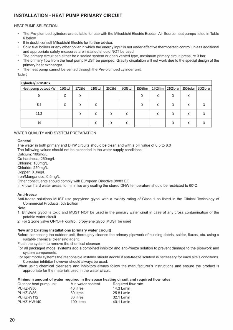
• The Pre-plumbed cylinders are suitable for use with the Mitsubishi Electric Ecodan Air Source heat pumps listed in Table 6 below
• If in doubt consult Mitsubishi Electric for further advice.• Solid fuel boilers or any other boiler in which the energy input is not under effective thermostatic control unless additional
and appropriate safety measures are installed should NOT be used.• The primary circuit can either be a sealed system or open vented type, maximum primary circuit pressure 3 bar.• The primary flow from the heat pump MUST be pumped. Gravity circulation will not work due to the special design of the
primary heat exchanger. • The heat pump cannot be vented through the Pre-plumbed cylinder unit.
Cylinder/HP Matrix150Std 170Std 210Std 250Std 300Std 150Slim 170Slim 210Solar 250Solar 300Solar
X X X X X X
X X X X X X X X
X X X X X X X X
X X X X X X
Heat pump output kW
5
8.5
11.2
14
WATER QUALITY AND SYSTEM PREPARATION
GeneralThe water in both primary and DHW circuits should be clean and with a pH value of 6.5 to 8.0The following values should not be exceeded in the water supply conditions:Calcium: 100mg/LCa hardness: 250mg/LChlorine: 100mg/LChloride: 250mg/LCopper: 0.3mg/LIron/Manganese: 0.5mg/LOther constituents should comply with European Directive 98/83 ECIn known hard water areas, to minimise any scaling the stored DHW temperature should be restricted to 60oC
Anti-freezeAnti-freeze solutions MUST use propylene glycol with a toxicity rating of Class 1 as listed in the Clinical Toxicology of
Commercial Products, 5th EditionNote:1. Ethylene glycol is toxic and MUST NOT be used in the primary water ciruit in case of any cross contamination of the
potable water circuit2. For 2 zone valve ON/OFF control, propylene glycol MUST be used
New and Existing Installations (primary water circuit)Before connecting the outdoor unit, thoroughly cleanse the primary pipework of building debris, solder, fluxes, etc. using a
suitable chemical cleansing agent.Flush the system to remove the chemical cleanserFor all packaged model systems add a combined inhibitor and anti-freeze solution to prevent damage to the pipework and
system components.For split model systems the responsible installer should decide if anti-freeze solution is necessary for each site’s conditions.
Corrosion inhibitor however should always be used.When using chemical cleansers and inhibitors always follow the manufacturer’s instructions and ensure the product is
appropriate for the materials used in the water circuit.
Minimum amount of water required in the space heating circuit and required flow ratesOutdoor heat pump unit Min water content Required flow rate PUHZ-W50 40 litres 14.3 L/minPUHZ-W85 60 litres 25.8 L/minPUHZ-W112 80 litres 32.1 L/minPUHZ-HW140 100 litres 40.1 L/min
Table 6
21
MAIN CONTROLLER FLOW RATE LOOK UP
The main controller can now show you the flow rates by using Request Code 540 in the Service Menu (see FTC5 main manual).
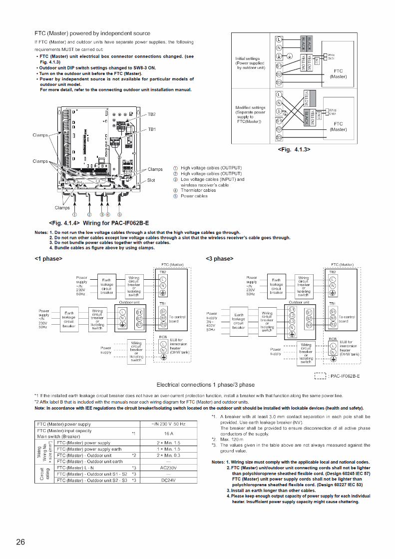
WIRING
All electrical wiring should be carried out by a competent electrician and be in accordance with the latest I.E.E. Wiring Regulations.
The Pre-plumbed cylinder thermal controls, primary circulating pumps are factory pre-wired. Further wiring will be required between the FTC5 controller, the programmer, room temperature sensor and the Heat Pump. Additional controls and wiring will be required if a second CH zone is to be fitted to the instalation.
Any thermal controls and over-temperature thermal cut-outs MUST NOT be bypassed.
The mains supply must be via a double pole isolating switch with a contact separation of at least 3mm in both poles. The supply must be fused 10 amp. A supply cable of 1.0 to 1.5mm2 cross sectional area should be used.
THIS APPLIANCE MUST BE EARTHED
HEATING SYSTEM CONTROLS
The controls provided with the Air Source Heat Pump pre-plumbed cylinder will ensure the safe operation of the unit within a central heating system.
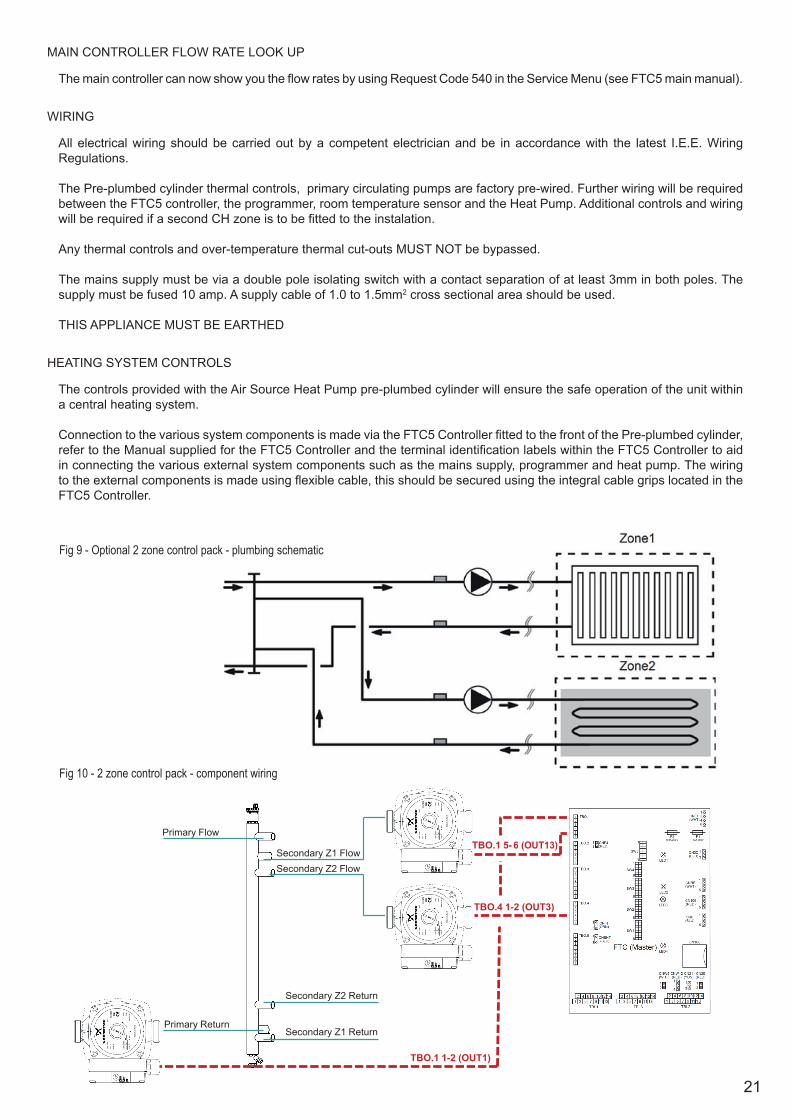
Connection to the various system components is made via the FTC5 Controller fitted to the front of the Pre-plumbed cylinder, refer to the Manual supplied for the FTC5 Controller and the terminal identification labels within the FTC5 Controller to aid in connecting the various external system components such as the mains supply, programmer and heat pump. The wiring to the external components is made using flexible cable, this should be secured using the integral cable grips located in the FTC5 Controller.
Primary Flow
Secondary Z1 Flow Secondary Z2 Flow
Secondary Z2 Return
Primary Return Secondary Z1 Return
TBO.1 1-2 (OUT1)
TBO.1 5- 6 (OUT13)
TBO.4 1-2 (OUT3)
Fig 9 - Optional 2 zone control pack - plumbing schematic
Fig 10 - 2 zone control pack - component wiring
22
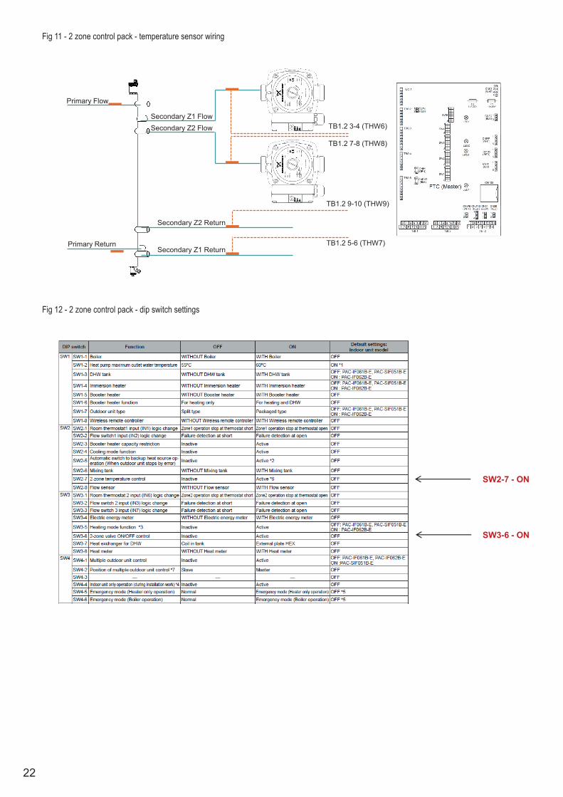
Primary Flow
Secondary Z1 Flow Secondary Z2 Flow
Secondary Z2 Return
Primary Return Secondary Z1 Return
TB1.2 3-4 (THW6)
TB1.2 5-6 (THW7)
TB1.2 7-8 (THW8)
TB1.2 9-10 (THW9)
SW2-7 - ON
SW3-6 - ON
Fig 11 - 2 zone control pack - temperature sensor wiring
Fig 12 - 2 zone control pack - dip switch settings
23
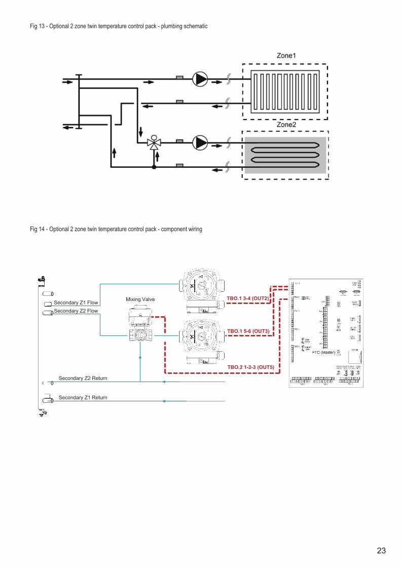
Fig 13 - Optional 2 zone twin temperature control pack - plumbing schematic
SW2-7 - ON
SW3-6 - ON
Secondary Z1 Flow Secondary Z2 Flow
Secondary Z2 Return
Secondary Z1 Return
TBO.1 3-4 (OUT2)
TBO.1 5-6 (OUT3)
Mixing Valve
TBO.2 1-2-3 (OUT5)
Fig 14 - Optional 2 zone twin temperature control pack - component wiring
24
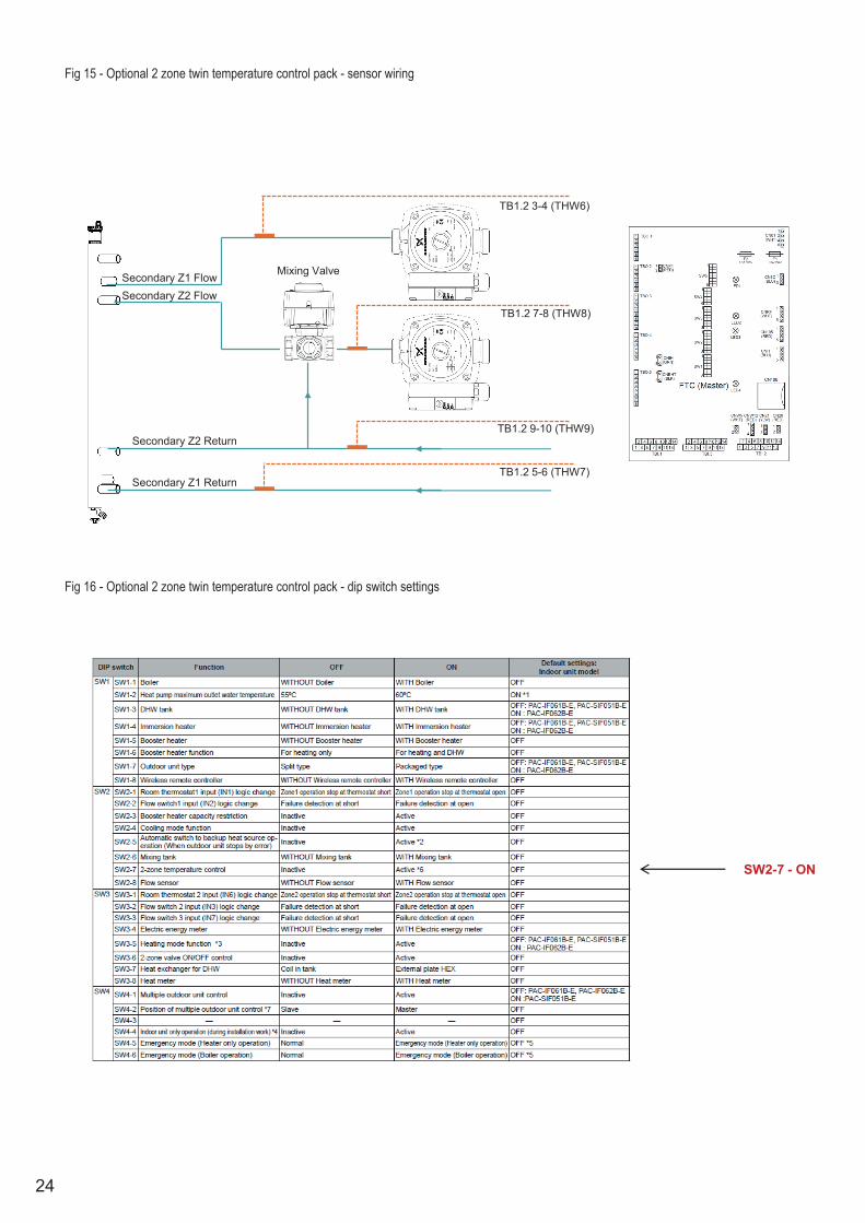
Secondary Z1 Flow Secondary Z2 Flow
Secondary Z2 Return
Secondary Z1 Return
Mixing Valve
TB1.2 3-4 (THW6)
TB1.2 5-6 (THW7)
TB1.2 7-8 (THW8)
TB1.2 9-10 (THW9)
SW2-7 - ON
Fig 15 - Optional 2 zone twin temperature control pack - sensor wiring
Fig 16 - Optional 2 zone twin temperature control pack - dip switch settings

25
Fig 17 - Wiring of Motorised Mixing valve Fig 18 - Schematic of Motorised Mixing Valve hydraulic connections
Fig 19 - Factory made conections to FTC5controller PCB
BLUE
BROWN TO RIGHT HAND PRIMARY PUMP
BLUE
BROWN
TO LEFT HAND PRIMARY PUMP (CABLE WITH WHITE ID TAG)
BLUE
BROWN
BLACK TO 3 WAY VALVE ACTUATOR HEAD
BROWN
WHITE
GREEN
TO FLOW SENSOR ASSEMBLY
TO TANK SENSOR (SENSOR TO BE INSERTED IN SPARE POCKET ON ELEMENT PLATE)
TANK SENSOR CONNECTION TO PCB BY MEANS OF WHITE JST PLUG CONNECTOR TO SOCKET CNW5
TO DHW CIRCULATING PUMP
DHW PUMP CONNECTION TO PCB BY MEANS OF RED JST PLUG CONNECTOR TO SOCKET CNP1
TO FLOW SENSOR (SENSOR TO BE INSERTED IN POCKET ON FLOW PIPE) GREY SLEEVING
TO RETURN SENSOR (SENSOR TO BE INSERTED IN POCKET ON RETURN PIPE) BLACK SLEEVING
FLOW AND RETURN SENSORS CONNECTION TO PCB BY MEANS OF RED JST PLUG CONNECTOR TO
ALL EARTH CONDUCTOR CONNECTIONS TO BE MADE TO EARTHING SCREWS ON FTC-5 CONTROLLER REAR CHASSIS
SW2-7 - ON
26

27
28
29
INSTALLATION - SOLAR PRIMARY
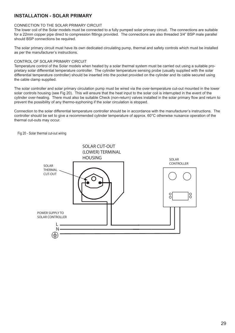
CONNECTION TO THE SOLAR PRIMARY CIRCUITThe lower coil of the Solar models must be connected to a fully pumped solar primary circuit. The connections are suitable for a 22mm copper pipe direct to compression fittings provided. The connections are also threaded 3/4” BSP male parallel should BSP connections be required.
The solar primary circuit must have its own dedicated circulating pump, thermal and safety controls which must be installed as per the manufacturer’s instructions.
CONTROL OF SOLAR PRIMARY CIRCUITTemperature control of the Solar models when heated by a solar thermal system must be carried out using a suitable pro-prietary solar differential temperature controller. The cylinder temperature sensing probe (usually supplied with the solar differential temperature controller) should be inserted into the pocket provided on the cylinder and its cable secured using the cable clamp supplied.
The solar controller and solar primary circulation pump must be wired via the over-temperature cut-out mounted in the lower solar controls housing (see Fig 20). This will ensure that the heat input to the solar coil is interrupted in the event of the cylinder over-heating. There must also be suitable Check (non-return) valves installed in the solar primary flow and return to prevent the possibility of any thermo-syphoning if the solar circulation is stopped.
Connection to the solar differential temperature controller should be in accordance with the manufacturer’s instructions. The controller should be set to give a recommended cylinder temperature of approx. 60°C otherwise nuisance operation of the thermal cut-outs may occur.
SOLARTHERMALCUT-OUT
SOLAR CUT-OUT (LOWER) TERMINAL HOUSING
LN
SOLARCONTROLLER
POWER SUPPLY TO SOLAR CONTROLLER
Fig 20 - Solar thermal cut-out wiring
30
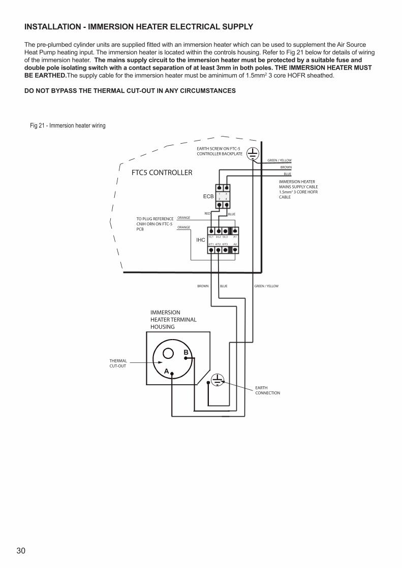
INSTALLATION - IMMERSION HEATER ELECTRICAL SUPPLY The pre-plumbed cylinder units are supplied fitted with an immersion heater which can be used to supplement the Air Source Heat Pump heating input. The immersion heater is located within the controls housing. Refer to Fig 21 below for details of wiring of the immersion heater. The mains supply circuit to the immersion heater must be protected by a suitable fuse and double pole isolating switch with a contact separation of at least 3mm in both poles. THE IMMERSION HEATER MUST BE EARTHED.The supply cable for the immersion heater must be aminimum of 1.5mm2 3 core HOFR sheathed.
DO NOT BYPASS THE THERMAL CUT-OUT IN ANY CIRCUMSTANCES
A
B
EARTHCONNECTION
2/T1 4/T2 6/T3 A2
1/L1 3/L2 5/L3 A1IHC
1
2 4
3ECB
RED BLUEORANGE
ORANGE
BLUEBROWN GREEN / YELLOW
THERMALCUT-OUT
IMMERSION HEATER TERMINAL HOUSING
GREEN / YELLOW
BLUE
BROWN
FTC5 CONTROLLERIMMERSION HEATERMAINS SUPPLY CABLE1.5mm2 3 CORE HOFRCABLE
TO PLUG REFERENCECNIH ORN ON FTC-5PCB
EARTH SCREW ON FTC-5CONTROLLER BACKPLATE
Fig 21 - Immersion heater wiring
31
COMMISSIONINGAt the time of commissioning, please ensure a Commissioning Checklist is completed for the installation.
FILLING THE UNIT WITH WATER
• BEFORE FILLING CHECK AND TIGHTEN ALL MECHANICAL JOINTS AND CONNECTIONS IN CASE THESE HAVE LOOSENED DURING TRANSIT.
• Check expansion vessel pre-charge pressure. The vessel is supplied precharged to 3.5 bar to match the control pressure of the pressure reducing valve. The precharge pressure is checked using a car tyre gauge by unscrewing the plastic cap opposite the water connection.
• Check all connections for tightness including the immersion heater(s). An immersion heater key spanner is supplied for this purpose.
• Ensure the drain cock is CLOSED. • Open a hot tap furthest from the cylinder.• Open the cylinder isolating valve to fill the unit. When water flows from the tap, allow to run for a few minutes to thoroughly
flush through any residue, dirt or swarf, then close the tap.• Open successive hot taps to purge the system of air.
SYSTEM CHECKS
• Check all water connections for leaks and rectify as necessary.• Turn off water supply to the cylinder.• Remove the pressure reducing valve head work to access the strainer mesh, clean and re-fit.• Manually open, for a few seconds, each relief valve in turn, checking that water is discharged and runs freely through
the tundish and out at the discharge point. • Ensure that the valve(s) reseat satisfactorily.
DOMESTIC HOT WATER (DHW) CIRCULATION
Ensure the DHW circulation pump is set to speed setting II to ensure optimum DHW heating performance. Failure todo so can result in excessive use of the back-up immersion heater or lower storage temperatures than required.
PRIMARY CIRCUIT
Fill the primary circuit following the Air Source Heat Pump commissioning instructions. Vent any trapped air. Check the primary system for leaks and rectify as necessary. Flush the primary system in accordance with the instructions on Page 20 and add a suitable inhibitor and anti-freeze solution when re-filling.
Switch on the electrical supply to the Air Source Heat Pump and immersion heater. Programme the Air Source Heat Pump controller as detailed in the fitting and user instructions supplied with the controller. Set the controller for hot water operation only. After a short delay the primary pump on the return to the Heat Pump and the DHW pump should run and the Heat Pump operate. The temperature of the primary flow to the cylinder should increase, if it does not, check for a wiring or piping error.
Allow the unit to heat up.
Select the heating only function on the controller. Both primary pumps should run and the Heat Pump operates. The primary flow to the cylinder primary pipework manifold and the radiator circuit should become hot, if it does not check for a wiring or piping error.
The minimum hot water setting is 40 °C. The maximum hot water setting is 60 °C. In hard water areas a maximum of 60 oC is recommended.
When the heating and hot water temperatures are reached, the pumps should stop running and the Heat Pump stop operating.
Check that no water is discharged from either the expansion valve or temperature and pressure relief valve during the heating cycle. If the user temperatures or “On” and “Off” times have been adjusted for commissioning purposes, the controller should be reset to the desired settings. The operation of the controller should be demonstrated to the user and the controller installation and user instructions left with them for future reference.
AUTOMATIC SYSTEM BY-PASS
An automatic differential bypass valve is supplied loose with the cylinder. This should be installed between the primary flow and the primary return to the main space heating zone from the Low Loss Header such that a minimum flow rate can be maintained through the Heat Pump in the event of the heating circuit being satisfied. See Graph 2 on page 32 for setting details for the valve

32
Graph 2 - Bypass valve pressure vs volume
33
MAINTENANCE
MAINTENANCE REQUIREMENTS
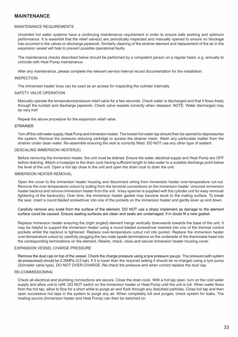
Unvented hot water systems have a continuing maintenance requirement in order to ensure safe working and optimum performance. It is essential that the relief valve(s) are periodically inspected and manually opened to ensure no blockage has occurred in the valves or discharge pipework. Similarly cleaning of the strainer element and replacement of the air in the expansion vessel will help to prevent possible operational faults.
The maintenance checks described below should be performed by a competent person on a regular basis, e.g. annually to coincide with Heat Pump maintenance.
After any maintenance, please complete the relevant service interval record documentation for the installation.
INSPECTION
The immersion heater boss can be used as an access for inspecting the cylinder internally.
SAFETY VALVE OPERATION
Manually operate the temperature/pressure relief valve for a few seconds. Check water is discharged and that it flows freely through the tundish and discharge pipework. Check valve reseats correctly when released. NOTE: Water discharged may be very hot!
Repeat the above procedure for the expansion relief valve.
STRAINER
Turn off the cold water supply, Heat Pump and immersion heater. The lowest hot water tap should then be opened to depressurise the system. Remove the pressure reducing cartridge to access the strainer mesh. Wash any particulate matter from the strainer under clean water. Re-assemble ensuring the seal is correctly fitted. DO NOT use any other type of sealant.
DESCALING IMMERSION HEATER(S)
Before removing the immersion heater, the unit must be drained. Ensure the water, electrical supply and Heat Pump are OFF before draining. Attach a hosepipe to the drain cock having sufficient length to take water to a suitable discharge point below the level of the unit. Open a hot tap close to the unit and open the drain cock to drain the unit.
IMMERSION HEATER REMOVAL
Open the cover to the immersion heater housing and disconnect wiring from immersion heater over-temperature cut-out. Remove the over-temperature cutout by pulling from the terminal connections on the immersion heater. Unscrew immersion heater backnut and remove immersion heater from the unit. A key spanner is supplied with the cylinder unit for easy removal/tightening of the backnut(s). Over time, the immersion heater gasket may become stuck to the mating surface. To break the seal, insert a round bladed screwdriver into one of the pockets on the immersion heater and gently lever up and down.
Carefully remove any scale from the surface of the element. DO NOT use a sharp implement as damage to the element surface could be caused. Ensure sealing surfaces are clean and seals are undamaged, if in doubt fit a new gasket.
Replace immersion heater ensuring the (right angled) element hangs vertically downwards towards the base of the unit. It may be helpful to support the immersion heater using a round bladed screwdriver inserted into one of the thermal control pockets whilst the backnut is tightened. Replace over-temperature cutout rod into pocket. Replace the immersion heater over-temperature cutout by carefully plugging the two male spade terminations on the underside of the thermostat head into the corresponding terminations on the element. Rewire, check, close and secure immersion heater housing cover.
EXPANSION VESSEL CHARGE PRESSURE
Remove the dust cap on top of the vessel. Check the charge pressure using a tyre pressure gauge. The pressure (with system de-pressurised) should be 0.35MPa (3.5 bar). If it is lower than the required setting it should be re-charged using a tyre pump (Schrader valve type). DO NOT OVER-CHARGE. Re-check the pressure and when correct replace the dust cap.
RE-COMMISSIONING
Check all electrical and plumbing connections are secure. Close the drain cock. With a hot tap open, turn on the cold water supply and allow unit to refill. DO NOT switch on the immersion heater or Heat Pump until the unit is full. When water flows from the hot tap, allow to flow for a short while to purge air and flush through any disturbed particles. Close hot tap and then open successive hot taps in the system to purge any air. When completely full and purged, check system for leaks. The heating source (immersion heater and Heat Pump) can then be switched on.

34
Fig 22 - Fernox TF-1 Compact Magnetic Filter assembly
ISOLATING VALVES( 2 OFF )
INLET / OUTLET PORT
ISOLATING VALVESEALING WASHERS( 2 OFF )FILTER BODY
DRAIN VALVE (DO NOTREMOVE)
CAP AND KEY
FILTER BODY CAP
MAGNET
AIR VENT
CAUTION: CONTAINS STRONG MAGNETIC FIELDSIF YOU HAVE AN IMPLANTED CARDIAC DEVICE EXTRA CAUTION SHOULD BE TAKEN WHEN HANDLING THE TF-1 COMPACT FILTER AND MAGNETIC CORE
CLEANING THE FERNOX TF-1 COMPACT MAGNETIC FILTER
Note: There is no need to remove the cap of the TF-1 filter for cleaningClose the isolating valves either side of the TF-1 magnetic filter. Remove the magnetic core by pulling upwards. Wait 30 seconds for any collected particles to settle in the filter body. Open the lower isolating valve then open the drain valve, collect any fluid and debris in a suitable container. Close the drain valve and open the upper isolating valve. Vent any trapped air from the filter by opening the air bleed screw on the cap. If necessary, re-pressurise the system using the filling loop fitted to the unit.
Should the cap need to be removed a spanner is provided in the accessory kit for this purpose. When replacing the cap a new ‘o’ ring should be used, this is also provided in the kit. Air can be vented by opening the bleed screw in the centre of the air vent valve, the complete valve does not need to be removed. Should the valve be removed a replacement ‘o’ ring should be used (provided in accessory kit) when re-assembling.
SERVICE LOG BOOK
On completion of any maintenance or service of the pre-plumbed cylinder, the Service Log Book should be filled in to record the actions taken and the date the work was undertaken.
35
FAULT FINDING & SERVICING
IMPORTANT
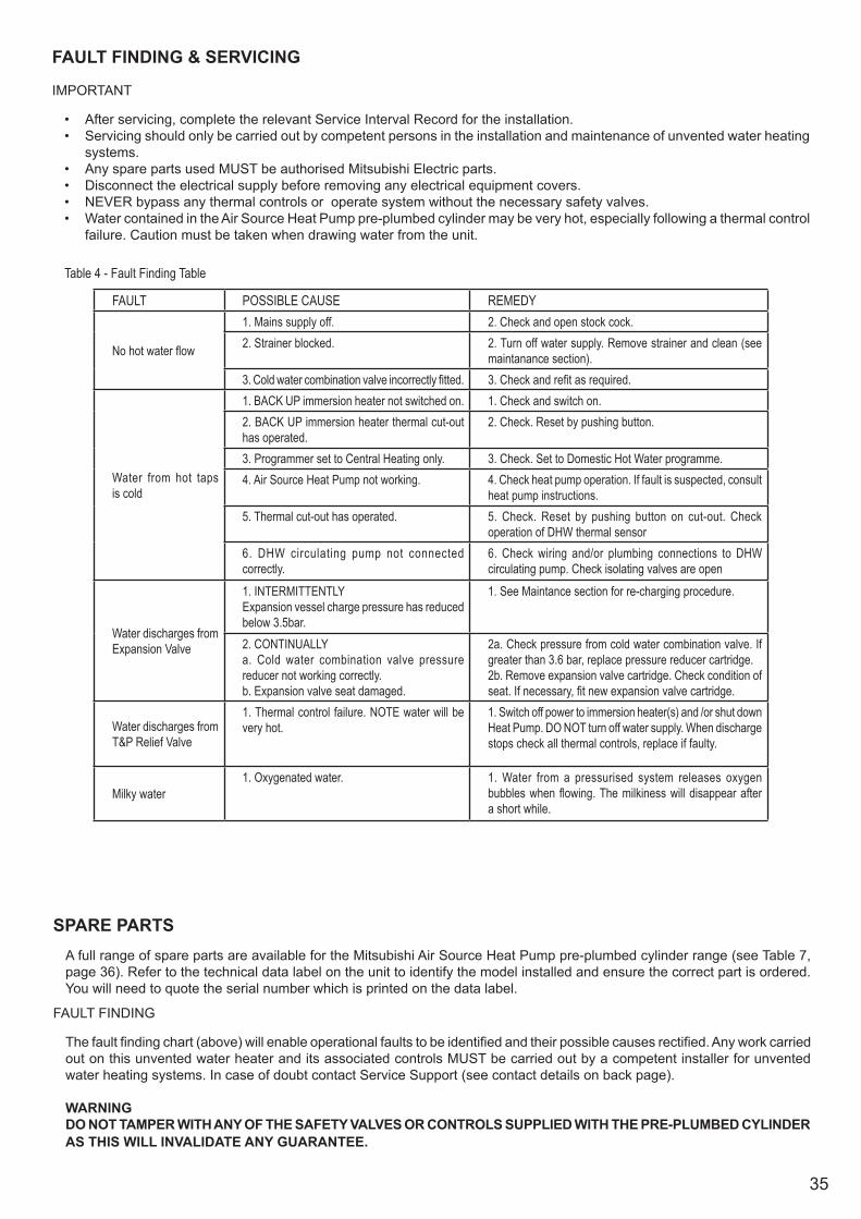
• After servicing, complete the relevant Service Interval Record for the installation.• Servicing should only be carried out by competent persons in the installation and maintenance of unvented water heating
systems.• Any spare parts used MUST be authorised Mitsubishi Electric parts.• Disconnect the electrical supply before removing any electrical equipment covers.• NEVER bypass any thermal controls or operate system without the necessary safety valves.• Water contained in the Air Source Heat Pump pre-plumbed cylinder may be very hot, especially following a thermal control
failure. Caution must be taken when drawing water from the unit.
SPARE PARTSA full range of spare parts are available for the Mitsubishi Air Source Heat Pump pre-plumbed cylinder range (see Table 7, page 36). Refer to the technical data label on the unit to identify the model installed and ensure the correct part is ordered. You will need to quote the serial number which is printed on the data label.
FAULT FINDING
The fault finding chart (above) will enable operational faults to be identified and their possible causes rectified. Any work carried out on this unvented water heater and its associated controls MUST be carried out by a competent installer for unvented water heating systems. In case of doubt contact Service Support (see contact details on back page).
WARNINGDO NOT TAMPER WITH ANY OF THE SAFETY VALVES OR CONTROLS SUPPLIED WITH THE PRE-PLUMBED CYLINDER AS THIS WILL INVALIDATE ANY GUARANTEE.
Table 4 - Fault Finding Table
FAULT POSSIBLE CAUSE REMEDY
No hot water flow
1. Mains supply off. 2. Check and open stock cock.2. Strainer blocked. 2. Turn off water supply. Remove strainer and clean (see
maintanance section).3. Cold water combination valve incorrectly fitted. 3. Check and refit as required.
Water from hot taps is cold
1. BACK UP immersion heater not switched on. 1. Check and switch on.2. BACK UP immersion heater thermal cut-out has operated.
2. Check. Reset by pushing button.
3. Programmer set to Central Heating only. 3. Check. Set to Domestic Hot Water programme.4. Air Source Heat Pump not working. 4. Check heat pump operation. If fault is suspected, consult
heat pump instructions.5. Thermal cut-out has operated. 5. Check. Reset by pushing button on cut-out. Check
operation of DHW thermal sensor6. DHW circulating pump not connected correctly.
6. Check wiring and/or plumbing connections to DHW circulating pump. Check isolating valves are open
Water discharges from Expansion Valve
1. INTERMITTENTLYExpansion vessel charge pressure has reduced below 3.5bar.
1. See Maintance section for re-charging procedure.
2. CONTINUALLYa. Cold water combination valve pressure reducer not working correctly.b. Expansion valve seat damaged.
2a. Check pressure from cold water combination valve. If greater than 3.6 bar, replace pressure reducer cartridge.2b. Remove expansion valve cartridge. Check condition of seat. If necessary, fit new expansion valve cartridge.
Water discharges from T&P Relief Valve
1. Thermal control failure. NOTE water will be very hot.
1. Switch off power to immersion heater(s) and /or shut down Heat Pump. DO NOT turn off water supply. When discharge stops check all thermal controls, replace if faulty.
Milky water1. Oxygenated water. 1. Water from a pressurised system releases oxygen
bubbles when flowing. The milkiness will disappear after a short while.
36
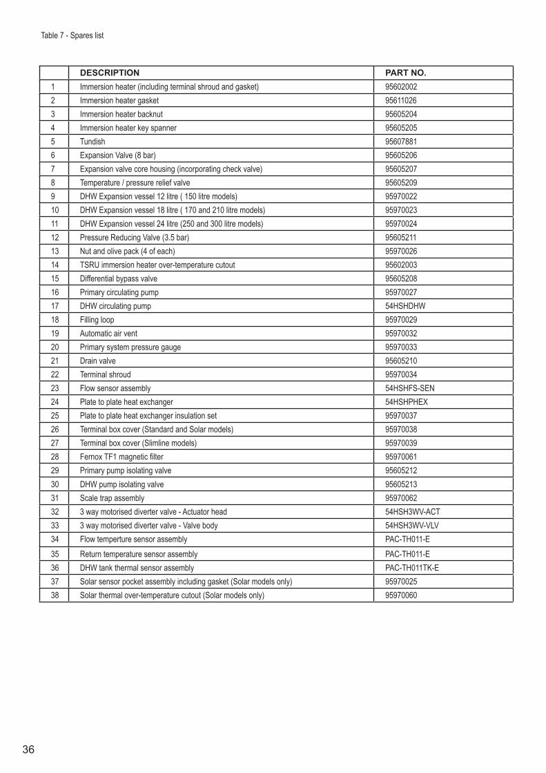
Table 7 - Spares list
DESCRIPTION PART NO.1 Immersion heater (including terminal shroud and gasket) 956020022 Immersion heater gasket 956110263 Immersion heater backnut 956052044 Immersion heater key spanner 956052055 Tundish 956078816 Expansion Valve (8 bar) 956052067 Expansion valve core housing (incorporating check valve) 956052078 Temperature / pressure relief valve 956052099 DHW Expansion vessel 12 litre ( 150 litre models) 9597002210 DHW Expansion vessel 18 litre ( 170 and 210 litre models) 9597002311 DHW Expansion vessel 24 litre (250 and 300 litre models) 9597002412 Pressure Reducing Valve (3.5 bar) 9560521113 Nut and olive pack (4 of each) 9597002614 TSRU immersion heater over-temperature cutout 9560200315 Differential bypass valve 9560520816 Primary circulating pump 9597002717 DHW circulating pump 54HSHDHW18 Filling loop 9597002919 Automatic air vent 9597003220 Primary system pressure gauge 9597003321 Drain valve 9560521022 Terminal shroud 9597003423 Flow sensor assembly 54HSHFS-SEN24 Plate to plate heat exchanger 54HSHPHEX25 Plate to plate heat exchanger insulation set 9597003726 Terminal box cover (Standard and Solar models) 9597003827 Terminal box cover (Slimline models) 9597003928 Fernox TF1 magnetic filter 9597006129 Primary pump isolating valve 9560521230 DHW pump isolating valve 9560521331 Scale trap assembly 9597006232 3 way motorised diverter valve - Actuator head 54HSH3WV-ACT33 3 way motorised diverter valve - Valve body 54HSH3WV-VLV34 Flow temperture sensor assembly PAC-TH011-E35 Return temperature sensor assembly PAC-TH011-E36 DHW tank thermal sensor assembly PAC-TH011TK-E37 Solar sensor pocket assembly including gasket (Solar models only) 9597002538 Solar thermal over-temperature cutout (Solar models only) 95970060
37
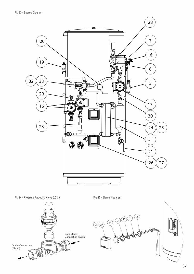
Fig 23 - Spares Diagram
Fig 24 - Pressure Reducing valve 3.5 bar Fig 25 - Element spares
Cold MainsConnection (22mm)
Outlet Connection(22mm)
2714
31 2
26
22
20
19
33
16
23
21
26 27
24
17
5
8
6
7
28
32
29
30
31
25
38
USER INSTRUCTIONS
WARNINGS
IF WATER ISSUES FROM THE TEMPERATURE/PRESSURE RELIEF VALVE ON THE PRE-PLUMBED CYLINDER, SHUT DOWN THE HEAT PUMP AND IMMERSION HEATER. DO NOT TURN OFF ANY WATER SUPPLY. CONTACT A COMPETENT INSTALLER FOR UNVENTED WATER HEATERS TO CHECK THE SYSTEM.
DO NOT TAMPER WITH ANY OF THE SAFETY VALVES FITTED TO THE PRE-PLUMBED CYLINDER. IF A FAULT IS SUSPECTED, CONTACT A COMPETENT INSTALLER.
COMMISSIONING RECORD
Please ensure that the installer has fully completed a Commissioning Checklist and Record for the installation and that you have signed it to say that you have received a full and clear explanation of its operation. The installer is legally required to complete a commissioning checklist as a means of complying with the appropriate Building Regulations (England and Wales).
All installations must be notified to Local Area Building Control either directly or through a Competent Persons Scheme. A Building Regulations Compliance Certificate will then be issued to the customer who should, on receipt, write the Notification Number on the Commissioning Checklist.
This product should be serviced regularly to optimise its safety, efficiency and performance. The service engineer should complete the relevant Service Record document after each service.
TEMPERATURE CONTROLS IMMERSION HEATER
The hot water storage temperature is set on the Programmer, the water temperature is sensed by means of a thermistor sensor located in a pocket on the immersion heater assembly. This should be set to give a water storage temperature of approx. 55° to 60°C. The immersion heater assembly is also fitted with an over-temperature cut-out. Access to the temperature sensor and over-temperature cut-out can be made by opening the immersion heater cover - DISCONNECT THE ELECTRICAL SUPPLY BEFORE OPENING THE COVER.
DO NOT bypass the thermal cut-out(s) in any circumstances.
HEATING BY HEAT PUMP
The space heating control temperature and the operating times for heating and hot water are set using the remotely mounted controller. The optimum temperatures and times will have been set during commissioning. Should the temperatures or timings need to be altered, refer to the installation and user instructions leaflet supplied with the controller for the method of adjustment.
FLOW PERFORMANCE
When initially opening hot outlets a small surge in flow may be noticed as pressures stabilise. This is quite normal with unvented systems. In some areas cloudiness may be noticed in the hot water. This is due to aeration of the water is quite normal and will quickly clear.
OPERATIONAL FAULTS
Operational faults and their possible causes are detailed in the Fault Finding section (page 35) of this manual. It is recommended that faults should be checked by a competent installer.
The air volume within the expansion vessel will periodically require recharging to ensure expanded water is accommodated within the unit. A discharge of water INTERMITTENTLY from the expansion valve will indicate the air volume has reduced to a point where it can no longer accommodate the expansion.

39
4036006282_issue_2
Telephone: 01707 282880
After Sales Service: 0161 866 6089Email: [email protected]: heating.mitsubishielectric.co.uk
UNITED KINGDOMMitsubishi Electric EuropeLiving Environmental Systems DivisionTravellers LaneHatfieldHertfordshireAL10 8XB
General EnquiriesTelephone: 01707 282880 Fax: 01707 278881
IRELANDMitsubishi Electric EuropeWestgate Business Park BallymountDublin 24Ireland
Telephone: Dublin (01) 419 8800 Fax: Dublin (01) 419 8890 International code: 00 3531
ENVIRONMENTAL INFORMATIONProducts are manufactured from many recyclable materials. At the end of their useful life they should be disposed of at a Local Authority Recycling Centre in order to realise the full environmental benefits.
Insulation is by means of an approved CFC/HCFC free polyurethane foam with an ozone depletion factor of zero.