Embed Size (px)
Citation preview

INSTALLATION INSTRUCTIONSAND USER GUIDE
GABARRON UNVENTED MAINS PRESSURE HOT WATER STORAGE CYLINDERS
Gabarron Direct 90 – 300 litresGabarron Indirect 90 – 300 litres
Please read these instructions before installing or

Page 2
Section Page
DESIGN Description 3 Technical Information 6 System Design 8 INSTALLATION Installation 10 Commissioning 18 USER INSTRUCTIONS 19 SERVICING AND MAINTENANCE Servicing and Maintenance 20 Fault Finding 21 Short Parts List 24
APPENDIX Appendix A 25 Appendix B 26
Notes 27
Terms & Conditions 28
Benchmark Checklist 30 Benchmark Service Record 31
ISSUE 2: FEBRUARY 2014These instructions should be read in conjunction with the installation/servicing instructions issued by the manufacturer of the heat source being used.
Any installation must be in accordance with the relevant requirements of the Gas Safety Regulations, Building Regulations, I.E.E. Wiring Regulations and the Water Fitting Regulations (England and Wales) or Water Byelaws (Scotland). It should be read in accordance with the relevant recommendations of the following:BS 6798; BS EN 12828, BS EN 12831, BS EN 14336; BS 5546;BS 5440:1; BS 5440:2; CP 331:3BS EN 806-1 to 5, BS EN 8558:2011: BS EN 1458-1:2011 and BS 7593:2006
Elnur Elnur Gabarrón cylinder is covered by Section G3 of the Building Regulations (England and Wales) Technical Standard P3 (Scotland) and Building Regulation P5 (Northern Ireland). Compliance can be achieved via a Competent Person Self Certification Scheme or notificaton of installation to the Local Authority Building Control Department.
It must be installed by a competent person as defined by the relevant regulations. Manufacturers notes must NOT be taken as over-riding statutory obligations.
This appliance is not intended for use by persons (including children) with reduced physical, sensory or mental capabilities, or lack of experience and knowledge unless they have been given supervision or instruction concerning use of the appliance by a person responsible for their safety. Children should be supervised at all times to ensure they do not play with the appliance.
This information is provided to assist generally in the selection of equipment.Responsibility for selection and specification of our equipment must however remain that of our customer and any experts or consultants concerned with the installation(s).
Please note: that we do not therefore accept any responsibility for matters of design selection or specification, for the effectiveness of an installation or system containing one of our products unless specifically requested to do so in writing.
All goods are sold subject to our Conditions of Sale which are set out at the rear of this specification. In the interest of continuously improving the Elnur Elnur Gabarrón cylinder range, Elnur UK Limited reserve the right to modify the product without notice, and in these circumstances this booklet, which is accurate at the time of printing, should be disregarded. An updated set of Instructions will be produced and supplied with new appliances and will be made available for other appliances on request.
Elnur Elnur Gabarrón cylinders is produced under an ISO 9001:2008 Quality Management System approved by BSI.
Benchmark places responsibilities on both manufacturers and installers. The purpose is to ensure that customers are provided with the correct equipment for their needs, that it is installed, commissioned and serviced in accordance with the manufacturers instructions by competent persons and that it meets the requirements of the appropriate Building Regulations. The Benchmark Checklist can be used to demonstrate compliance with Building Regulations and should be provided to the customer for future reference.
Installers are required to carry out installation, commissioning and servicing work in accordance with the Benchmark Code of Practice which is available from the Heating and Hot Water Industry Council who manage and promote the Scheme. Visit www.centralheating.co.uk for more information.

Page 3
Maintenance
Modifications should not be made to this product. Replacement parts, including immersion heaters, should be purchased from Elnur UK Limited, or agents approved by them. Unvented hot water storage vessels need regular routine checks, and these are detailed below. It is for this reason that this manual must always be left with the Elnur Elnur Gabarrón cylinder.
It is essential that these checks be carried out at the time of boiler maintenance by a qualified installer:
1. Manually open the relief valves in turn, and check that water is discharged from the valves and runs freely through the tundish and out at the discharge point. Ensure that the valves re-seat satisfactorily. (Note - the water may be very hot).
2. It is important to check that the discharge pipework is carrying the water away adequately. Check for blockages etc. if it is not.
3. Turn the mains water off and remove and clean the strainer element in the Pressure Reducing Valve.
4. Check the charge pressure in the expansion vessel and repressurise if required
5. Re-fill the system and ensure that all relief valves have re-seated.
6. The Benchmark Service Record should be updated at each service.
7. Check the water pressure downstream of the combination valve is 3 bar in static condition.
8. Check and if necessary, descale the heat exchanger in hard water areas ie. above 200ppm (mg/l).
Note:
The cylinder is factory fitted with a temperature & pressure relief valve that must not be used for any other purpose or removed.
The cylinder is factory fitted with immersion heaters with thermal cut outs. Immersions without thermal cut outs must not be fitted.
Manufacturer: Elnur UK Ltd
Maximum inlet pressure toPressure reducing valve 12 barOperating pressure (PRV setting) 3 barExpansion vessel charge pressure 3 barExpansion relief valve setting 4.75 barOpening pressure of P & T Relief Valve 6 barOpening temperature of P & T Relief Valve 92-95°CEnergy cut-out thermostat setting 85°CMax. working pressure - Primary heat exchanger (Indirect models) 6 barImmersion heater rating 3kW, 240V AC
All cylinders are manufactured in accordance with the requirements of BS EN 12897The tundish must be positioned so that it is visible to the occupant and is away from electrical devices.
Components supplied with Elnur Elnur Gabarrón cylinder:• Cold water inlet PRV combination valve/expansion relief• Pressure and temperature relief valve• Control thermostat• Energy cut-out thermostat• Energy cut-out motorised valve (indirects only)• Tundish• 3kW Immersion heater including control and cut out thermostats• Expansion vessel/mounting bracket• Technical/user product literature
(Note: Please refer to tables 1 and 2 on pages 6-9 to confirm the quantity of immersion heaters supplied with the unit)
In any situation where the volume of heated pipework (eg. secondary circulation pipes or manifold pipework for multiple units) exceeds 10 litres, then an additional expansion vessel must be fitted to accommodate the extra expansion volume.
Handling Before Installation
Elnur Gabarrón cylinder must be handled with care and stored the correct way up in a dry place. Any manual handling/lifting operations will need to comply with the requirements of the Manual Handling Operations Regulations issued by the H.S.E. The appliance can be moved using a sack truck on the rear face although care should be taken and the route should be even. In apartment buildings containing a number of storeys we would recommend that the appliances are moved vertically in a mechanical lift. If it is proposed to use a crane, expert advice should be obtained regarding the need for slings, lifting beams etc.
A specific manual handling assessment is shown in Appendix B at the rear of this manual.
DESIGN
DESCRIPTION
Page 4
Elnur Gabarrón cylinders are a range of unvented hot water storage cylinders, manufactured in the latest high quality duplex stainless steel. They are designed to provide mains pressure hot water and are supplied as a package which complies with Section G3 of the Building Regulations. The appliance is extremely well insulated using high density HCFC free foam insulation with an ozone depleting potential (ODP) of zero and a global warming potential (GWP) of 1. It is fitted with all necessary safety devices and supplied with all the necessary control devices to make installation on site as easy as possible.
Elnur Gabarrón cylinders are available in two basic variants:
1. Elnur Gabarrón Direct - For providing hot water heated by electricity (Figure 1).
2. Elnur Gabarrón Indirect - For use with gas or oil boilers (Figure 2). Unvented cylinders must not be used with solid fuel boilers or steam as the energy source.
Elnur Gabarrón Direct
Elnur Gabarrón direct is an electrically heated, unvented hot water storage cylinder designed primarily for use with off peak electrical supplies.
It is supplied fitted with two 3kW immersion heaters which are BEAB approved for safety as recommended by the Electricity Council.
Elnur Gabarrón direct models are listed in Table 1 on Page 6 & 7.
Elnur Gabarrón DIRECT
Figure 1
Pipework is not supplied by manufacturer,but to be supplied and fitted by installer.
DESIGN
DESCRIPTION
Page 5
Elnur Gabarrón INDIRECT
Figure 2
Pipework is not supplied by manufacturer,but to be supplied and fitted by installer.
Elnur Gabarrón Indirect
Elnur Gabarrón indirect is an unvented hot water storage cylinder and is provided with a high efficiency internal primary coil which is designed for use with a gas or oil boiler and is suitable for both open vented and sealed pumped primary systems.
When used with a sealed heating system the boiler must incorporate its own energy cut-out overheat thermostat.
Elnur Gabarrón indirect models are listed in Table 1 on Page 6 & 7.
Note:The cold supply elbow c/w drain tapping must be fitted as shown in figs 1 and 2. A flexible hose can then be connected to the drain tapping and, providing the hose runs below the lowest level of the cylinder, then all the water contents can be drained out by syphonic action. (The cold feed pipe dips internally to the base of the cylinder.)
DESIGN
DESCRIPTION

Page 6
Table 1
Mod
el
Wei
ght -
Em
pty
Wei
ght -
Ful
l
Capa
city
(Tot
al V
olum
e)
Pres
sure
Reg
ulat
or 3
bar
inle
tgr
oup
c/w
bal
ance
col
d su
pply
, ex
pans
ion
vess
el c
onne
ctio
n an
d ex
pans
ion
valv
e se
t at 4
.75
bar
Expa
nsio
n Ve
ssel
siz
e.Pr
e-ch
arge
d to
3 b
ar
Ove
rall
Hei
ght
Ove
rall
Dia
met
er
Pres
sure
& T
empe
ratu
reRe
lief V
alve
6ba
r 95°
C
22m
m S
econ
dary
Retu
rn T
appi
ng
On
Peak
Imm
ersi
onH
eate
r - H
igh
Leve
l
Cold
Fee
d 22
mm
Conn
ecti
on
Off
Pea
k Im
mer
sion
Hea
ter -
Low
Lev
el
Volu
me
of O
n Pe
ak W
ater
Hea
ted
Dua
l Con
trol
& O
verh
eat S
tat
Extr
a St
at P
ocke
tFo
r Boi
ler U
se If
Req
uire
d
22m
m P
rim
ary
Retu
rn
Conn
ecti
on
22m
m P
rim
ary
Flow
Con
nect
ion
kW R
atin
g of
Pri
mar
y Co
il
Surf
ace
Are
a of
Prim
ary
Hea
ter C
oil
Pres
sure
Los
s A
cros
sPr
imar
y H
eate
r Coi
l
Hea
t Up
Tim
e fr
om 1
5°C
to 6
0°C
(app
lies t
o Pr
imar
y Hea
t Sou
rce
only
)
Reco
very
Tim
e af
ter 7
0% D
raw
Off
(app
lies t
o Pr
imar
y Hea
t Sou
rce
only
)
Stan
ding
Los
ses
kWhr
/24h
r
kg kg Litres bar Litres A=mm mm B=mm C=mm D=mm E=mm F=mm Litres G=mm H=mm I=mm J=mm kW m2 bar min min kWh
Direct
ASLNORELND90 13 103 90 3 12 745 550 490 n/a n/a 367 223 n/a n/a n/a n/a n/a n/a n/a n/a 90 58 0.85
ASLNORELND120 18 138 120 3 12 930 550 678 n/a 487 367 223 55 n/a n/a n/a n/a n/a n/a n/a 119 90 1.06
ASLNORELND150 22 172 150 3 18 1120 550 865 n/a 587 442 223 70 n/a n/a n/a n/a n/a n/a n/a 150 121 1.27
ASLNORELND180 24 204 180 3 18 1305 550 1053 n/a 686 442 223 85 n/a n/a n/a n/a n/a n/a n/a 179 157 1.48
ASLNORELND210 28 238 210 3 24 1495 550 1241 1127 786 442 223 90 n/a n/a n/a n/a n/a n/a n/a 209 192 1.70
ASLNORELND250 32 282 250 3 24 1745 550 1491 1377 927 522 223 125 n/a n/a n/a n/a n/a n/a n/a 249 224 1.85
ASLNORELND300 37 337 300 3 35 1992 550 1720 1577 1077 522 223 155 n/a n/a n/a n/a n/a n/a n/a 299 263 2.04
Indirect
ASLNORELNIND90 19 109 90 3 12 745 550 490 n/a 352 367 n/a 40 367 367 223 312 16.5 0.59 0.165 21 16 0.85
ASLNORELNIND120 22 142 120 3 12 930 550 678 n/a 352 367 n/a 67 367 367 223 312 18 0.59 0.165 27 19 1.06
ASLNORELNIND150 26 176 150 3 18 1120 550 865 n/a 392 442 n/a 92 407 407 223 392 18.5 0.68 0.191 28 19 1.27
ASLNORELNIND180 28 208 180 3 18 1305 550 1053 n/a 432 442 n/a 116 447 447 223 392 19 0.78 0.216 33 21 1.48
ASLNORELNIND210 33 243 210 3 24 1495 550 1241 1127 432 442 n/a 145 482 482 223 392 20.5 0.78 0.216 41 26 1.70
ASLNORELNIND250 38 288 250 3 24 1745 550 1491 1377 927 522 512 109 577 577 223 472 21.5 0.97 0.241 44 30 1.85
ASLNORELNIND300 44 344 300 3 35 1992 550 1720 1577 1077 522 512 130 677 677 223 522 25 0.97 0.241 48 32 2.04
A
C
Direct
D
F
E
B
DESIGN
TECHNICAL INFORMATION
A
C
Indirect
DH F E
I
J
BG

Page 7
Table 1
Mod
el
Wei
ght -
Em
pty
Wei
ght -
Ful
l
Capa
city
(Tot
al V
olum
e)
Pres
sure
Reg
ulat
or 3
bar
inle
tgr
oup
c/w
bal
ance
col
d su
pply
, ex
pans
ion
vess
el c
onne
ctio
n an
d ex
pans
ion
valv
e se
t at 4
.75
bar
Expa
nsio
n Ve
ssel
siz
e.Pr
e-ch
arge
d to
3 b
ar
Ove
rall
Hei
ght
Ove
rall
Dia
met
er
Pres
sure
& T
empe
ratu
reRe
lief V
alve
6ba
r 95°
C
22m
m S
econ
dary
Retu
rn T
appi
ng
On
Peak
Imm
ersi
onH
eate
r - H
igh
Leve
l
Cold
Fee
d 22
mm
Conn
ecti
on
Off
Pea
k Im
mer
sion
Hea
ter -
Low
Lev
el
Volu
me
of O
n Pe
ak W
ater
Hea
ted
Dua
l Con
trol
& O
verh
eat S
tat
Extr
a St
at P
ocke
tFo
r Boi
ler U
se If
Req
uire
d
22m
m P
rim
ary
Retu
rn
Conn
ecti
on
22m
m P
rim
ary
Flow
Con
nect
ion
kW R
atin
g of
Pri
mar
y Co
il
Surf
ace
Are
a of
Prim
ary
Hea
ter C
oil
Pres
sure
Los
s A
cros
sPr
imar
y H
eate
r Coi
l
Hea
t Up
Tim
e fr
om 1
5°C
to 6
0°C
(app
lies t
o Pr
imar
y Hea
t Sou
rce
only
)
Reco
very
Tim
e af
ter 7
0% D
raw
Off
(app
lies t
o Pr
imar
y Hea
t Sou
rce
only
)
Stan
ding
Los
ses
kWhr
/24h
r
kg kg Litres bar Litres A=mm mm B=mm C=mm D=mm E=mm F=mm Litres G=mm H=mm I=mm J=mm kW m2 bar min min kWh
Direct
ASLNORELND90 13 103 90 3 12 745 550 490 n/a n/a 367 223 n/a n/a n/a n/a n/a n/a n/a n/a 90 58 0.85
ASLNORELND120 18 138 120 3 12 930 550 678 n/a 487 367 223 55 n/a n/a n/a n/a n/a n/a n/a 119 90 1.06
ASLNORELND150 22 172 150 3 18 1120 550 865 n/a 587 442 223 70 n/a n/a n/a n/a n/a n/a n/a 150 121 1.27
ASLNORELND180 24 204 180 3 18 1305 550 1053 n/a 686 442 223 85 n/a n/a n/a n/a n/a n/a n/a 179 157 1.48
ASLNORELND210 28 238 210 3 24 1495 550 1241 1127 786 442 223 90 n/a n/a n/a n/a n/a n/a n/a 209 192 1.70
ASLNORELND250 32 282 250 3 24 1745 550 1491 1377 927 522 223 125 n/a n/a n/a n/a n/a n/a n/a 249 224 1.85
ASLNORELND300 37 337 300 3 35 1992 550 1720 1577 1077 522 223 155 n/a n/a n/a n/a n/a n/a n/a 299 263 2.04
Indirect
ASLNORELNIND90 19 109 90 3 12 745 550 490 n/a 352 367 n/a 40 367 367 223 312 16.5 0.59 0.165 21 16 0.85
ASLNORELNIND120 22 142 120 3 12 930 550 678 n/a 352 367 n/a 67 367 367 223 312 18 0.59 0.165 27 19 1.06
ASLNORELNIND150 26 176 150 3 18 1120 550 865 n/a 392 442 n/a 92 407 407 223 392 18.5 0.68 0.191 28 19 1.27
ASLNORELNIND180 28 208 180 3 18 1305 550 1053 n/a 432 442 n/a 116 447 447 223 392 19 0.78 0.216 33 21 1.48
ASLNORELNIND210 33 243 210 3 24 1495 550 1241 1127 432 442 n/a 145 482 482 223 392 20.5 0.78 0.216 41 26 1.70
ASLNORELNIND250 38 288 250 3 24 1745 550 1491 1377 927 522 512 109 577 577 223 472 21.5 0.97 0.241 44 30 1.85
ASLNORELNIND300 44 344 300 3 35 1992 550 1720 1577 1077 522 512 130 677 677 223 522 25 0.97 0.241 48 32 2.04
40,00º 45,00º35,00º25,00º
15,00º
NOTES
1. Not all models - see table 1.2. Recovery times based on Primary
Coil/I.H. duty (ie. assumes the boiler output is adequate).
3. The diagrams shown are generic. For exact product specification refer to the table eg. the number of immersion heaters varies depending on model.
4. Heat up and recovery times based on 0.25 l/s primary flow rate and at 82°C flow temperature.
DESIGN
TECHNICAL INFORMATION

Page 8
Elnur Gabarrón Direct
Basic Appliance1. Hot water draw off (22mm) 2. Temperature & pressure relief valve 92-95°/6 bar3. Hot water secondary return 22mm (not fitted to smaller sizes, see table 1)4. Immersion heater 1¾” BSP 3kW (normally on-peak)5. 22mm cold supply6. Immersion heater 1¾” BSP 3kW (normally off-peak)
Part G3 loose components supplied in a separate boxA. Combination inlet group incorporating
pressure reducing valve, strainer, check valve, balance cold take off point, expansion relief valve and expansion vessel connection points.
B. Portable expansion vessels c/w wall bracketC. Tundish
1
2
5
3
4
6
Typical arrangement of component kit shown fitted to the appliance for clarityPipework to be supplied and fitted by installer.
DESIGN
SYSTEM DESIGN
Page 9
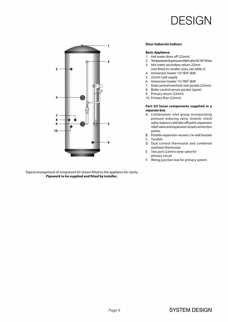
Elnur Gabarrón Indirect
Basic Appliance1. Hot water draw off (22mm) 2. Temperature & pressure relief valve 92-95°/6 bar3. Hot water secondary return 22mm (not fitted to smaller sizes, see table 2)4. Immersion heater 1¾” BSP 3kW5. 22mm cold supply6. Immersion heater 1¾” BSP 3kW7. Dual control/overheat stat pocket (22mm)8. Boiler control sensor pocket (spare)9. Primary return (22mm)10. Primary flow (22mm)
Part G3 loose components supplied in a separate boxA. Combination inlet group incorporating
pressure reducing valve, strainer, check valve, balance cold take off point, expansion relief valve and expansion vessel connection points.
B. Potable expansion vessels c/w wall bracketC. TundishD. Dual control thermostat and combined
overheat thermostatE. Two port (22mm) zone valve for primary circuitF. Wiring junction box for primary system
1
2
3
4
7
56
9
8
10
Typical arrangement of component kit shown fitted to the appliance for clarityPipework to be supplied and fitted by installer.
DESIGN
SYSTEM DESIGN

Page 10
General Design Considerations
The cupboard footprint needs to be at least 650mm square for standard units. The base chosen for the cylinder should be level and capable of supporting the weight of the unit when full of water as shown in General Data. The discharge pipework for the safety valves must have a minimum fall of 1 : 200 from the unit to a safe discharge point. All exposed pipework and fittings on the cylinder should be insulated, and the unit should NOT be fixed in a location where the contents could freeze.
In new systems, pipes should be insulated to comply with building regs, the maximum permissible heat loss is indicated in the table opposite, and labelled accordingly as follows:i. Primary circulation pipes for domestic hot water circuits should be insulated
through their length, subject only to practical constraints imposed by the need to penetrate joists and other structural elements.
ii. All pipes connected to hot water storage vessels, including the vent pipe, should be insulated for at least 1 metre from their points of connection to the cylinder (or they should be insulated up to the point where they become concealed).
In replacement systems, whenever a boiler or hot water storage vessel is replaced in an existing system, any pipes that are exposed as part of the work or are otherwise accessible should be insulated as recommended for new systems, or to some lesser standard where practical constraints dictate.
The pipe connecting the boiler flow to the appliance must not be less than 22mm copper or equivalent.
Model Selection Guide
Max hot water demandMax number of bed spaces
(Bedrooms)
Indirect litres
Direct litres
1 shower room Bedsit (0) 90 120
1 bathroom 2 (2) 120 150
1 bathroom 4 (3) 120 180
1 bathroom + separate shower room 6 (4) 150 210
1 bathroom + 2 separate shower rooms or 2 bathrooms 7 (5) 180 210
2 bathrooms + separate shower room 7 (5) 210 250
2 bathrooms + 2 separate shower rooms 7 (5) 250 300
3 bathrooms + 2 separate showers rooms 9 (6) 300 -
INSTALLATION
INSTALLATION
Further guidance on converting heat loss limits to insulation thickness for specific thermal conductivities is available in TIMSA “HVAC guidance for achieving compliance with Part L of the Building Regulations”.
Mains Water Supply
Existing properties with a 15mm supply will be satisfactory provided the local mains pressure is good, but should be confined to single bathroom properties. For new properties where simultaneous demand is required to more than one bathroom or a bathroom and one or more en-suites, the communication and service pipe into the dwelling should be a minimum of 22mm (usually in the form of a 25mm MDPE supply). The optimum performance is achieved if the inlet pressure is 3 bar dynamic. However, the Elnur Gabarrón cylinder will function with lower inlet pressures, but this will reduce the performance. For optimum performance, 30L per minute incoming mains flow should be present, however the Elnur Gabarrón cylinder will work at lower flow rates, although performance will be affected. Normally Elnur Gabarrón cylinder provides well in excess of 40 litres/min in most conditions. Flow rates for ALL mains pressure systems are subject to district pressures and system dynamic loss. Particularly on larger properties with more than one bathroom, the pipe sizes should be calculated in accordance with BS EN 806-3:2006 and BS 8558:2011.
Model Selection
The suggested Direct model sizes, shown opposite, are based on a typical days hot water use assuming an Economy 7 tariff is provided. A reduction of one model size can normally be made with an Economy 10 tariff. When using the Direct models for high specification developments an increase of one model size should be considered.
The suggested model sizes are based on typical hot water usage. For high specification dwellings an increase of one model size should be considered.
Insulation of pipework
Pipe outside diameter
Maximumheat loss
15mm 7.89W/m
22mm 9.12W/m
28mm 10.07W/m
35mm 11.08W/m

Page 11
INCOMING COLD SUPPLY
MDC
DC
DC
TOEXTERNALTAP
SINK
WATER SOFTENER (IF NECESSARY)
WM or DWM
WHB W.C.
DC
DC
SH
DHW
WHBWC BATH
SCV SCV
P&T
ERV/NRVPRV
DCV
Note:
Cold supplies to single taps must be taken from the mains cold water system.
Cold supplies to mixer taps must be taken from the balanced cold water connection on the combination valve.
General Restrictions
a. The highest hot or cold water draw off point should not exceed 10 metres above the Pressure Reducing Valve.
b. An ascending spray type bidet or any other appliance with a Class 1 back-syphonage risk requiring a type A air gap should not be used.
c. Elnur Gabarrón cylinder should not be used where steam is the primary heating medium, or in a situation where maintenance is likely to be neglected.
d. Unvented cylinders are not suitable for use with solid fuel boilers.e. If the supply to the mixer fittings (other than a dual outlet type) is not taken from
the balanced supply the system will become over pressurized and cause the pressure relief valve to discharge. Over time this could also cause the premature failure of the appliance itself which will not be covered by the warranty.
f. In larger properties with a number of bathrooms/en-suites and long pipe runs we would recommend that the balance cold supply is provided with its own pressure reducing valve and is not taken from the balanced cold connection on the combination valve. In this case it will also be necessary to fit a small expansion vessel on the balanced cold water system to accommodate the pressure rise caused by the increase in temperature of the balanced cold water.
g. Check the performance requirements of the terminal fittings with regard to flow/pressure are suitable.
h. In relation to potable water systems, expansion vessels shall be installed in a vertical orientation and located so that the length of the connecting pipe work is kept to a minimum.
Shower Fittings
Aerated taps are recommended to prevent splashing. Any type of shower mixing valve can be used as long as both the hot and cold supplies are mains fed. However, all mains pressure systems are subject to dynamic changes particularly when other hot and cold taps/showers are opened and closed, which will cause changes in the water temperature at mixed water outlets such as showers. For this reason and because these are now no more expensive than a manual shower we strongly recommend the use of thermostatic showers with this appliance. These must be used in 3 storey properties where the impact on pressure/temperature of opening another tap in the system is greater than normal. The shower head provided must also be suitable for mains pressure supplies.
Pipe Layout
In all mains pressure installations it is important to remember that the incoming cold supply must be shared between all terminal fittings. It is important that a 22mm supply is brought to the appliance and a 22mm take-off is continued at least to the bath. If there are two baths, 28mm pipework should be considered. One metre of smaller diameter pipework, or flow restrictors, should be provided on the final connection to all outlets so as to balance the water available. In any event the distribution pipework should generally be in accordance with BS EN806-1 to 5.
Plastic Pipework
This appliance is suitable for use with plastic pipework as long as the material is recommended for the purpose by the manufacturer and is installed fully in accordance with their recommendations.
Secondary Hot Water Circulation
Some models are fitted with a secondary return tapping as standard (see tables 1 and 2 for details). If fitted, an extra expansion vessel may be necessary. A non-return valve MUST be FITTED near the return connection. No valve or terminal fitting should be installed between the non return valve and the cylinder. (See schematic arrangement on page 15.) All pipes kept hot by the secondary circulation should be insulated.
INSTALLATION
INSTALLATION
Page 12
15 mmdischargepipe
Expansionrelief valve
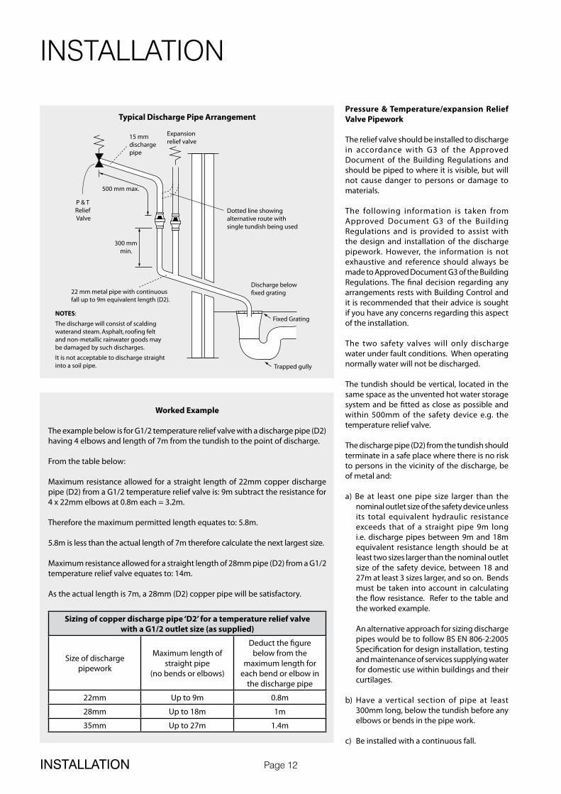
Typical Discharge Pipe Arrangement
Dotted line showingalternative route withsingle tundish being used
500 mm max.
P & T Relief Valve
300 mmmin.
22 mm metal pipe with continuousfall up to 9m equivalent length (D2).
NOTES:
The discharge will consist of scaldingwaterand steam. Asphalt, roofing feltand non-metallic rainwater goods maybe damaged by such discharges.
It is not acceptable to discharge straightinto a soil pipe.
Discharge belowfixed grating
Fixed Grating
Trapped gully
Pressure & Temperature/expansion Relief Valve Pipework
The relief valve should be installed to discharge in accordance with G3 of the Approved Document of the Building Regulations and should be piped to where it is visible, but will not cause danger to persons or damage to materials.
The following information is taken from Approved Document G3 of the Building Regulations and is provided to assist with the design and installation of the discharge pipework. However, the information is not exhaustive and reference should always be made to Approved Document G3 of the Building Regulations. The final decision regarding any arrangements rests with Building Control and it is recommended that their advice is sought if you have any concerns regarding this aspect of the installation.
The two safety valves will only discharge water under fault conditions. When operating normally water will not be discharged.
The tundish should be vertical, located in the same space as the unvented hot water storage system and be fitted as close as possible and within 500mm of the safety device e.g. the temperature relief valve.
The discharge pipe (D2) from the tundish should terminate in a safe place where there is no risk to persons in the vicinity of the discharge, be of metal and:
a) Be at least one pipe size larger than the nominal outlet size of the safety device unless its total equivalent hydraulic resistance exceeds that of a straight pipe 9m long i.e. discharge pipes between 9m and 18m equivalent resistance length should be at least two sizes larger than the nominal outlet size of the safety device, between 18 and 27m at least 3 sizes larger, and so on. Bends must be taken into account in calculating the flow resistance. Refer to the table and the worked example.
An alternative approach for sizing discharge pipes would be to follow BS EN 806-2:2005 Specification for design installation, testing and maintenance of services supplying water for domestic use within buildings and their curtilages.
b) Have a vertical section of pipe at least 300mm long, below the tundish before any elbows or bends in the pipe work.
c) Be installed with a continuous fall.
Worked Example
The example below is for G1/2 temperature relief valve with a discharge pipe (D2) having 4 elbows and length of 7m from the tundish to the point of discharge.
From the table below:
Maximum resistance allowed for a straight length of 22mm copper discharge pipe (D2) from a G1/2 temperature relief valve is: 9m subtract the resistance for 4 x 22mm elbows at 0.8m each = 3.2m.
Therefore the maximum permitted length equates to: 5.8m.
5.8m is less than the actual length of 7m therefore calculate the next largest size.
Maximum resistance allowed for a straight length of 28mm pipe (D2) from a G1/2 temperature relief valve equates to: 14m.
As the actual length is 7m, a 28mm (D2) copper pipe will be satisfactory.
Sizing of copper discharge pipe ‘D2’ for a temperature relief valvewith a G1/2 outlet size (as supplied)
Size of discharge pipework
Maximum length of straight pipe
(no bends or elbows)
Deduct the figure below from the
maximum length for each bend or elbow in
the discharge pipe
22mm Up to 9m 0.8m
28mm Up to 18m 1m
35mm Up to 27m 1.4m
INSTALLATION
INSTALLATION

Page 13
d) It is preferable for the discharge to be visible at both the tundish and the final point of discharge but where this is not possible or practically difficult there should be clear visibility at one or other of these locations. Examples of acceptable discharge arrangements are:
1. Ideally below the fixed grating and above the water seal in a trapped gulley.
2. Downward discharges at a low level; i.e. up to 100mm above external surfaces such as car parks, hard standings, grassed areas etc are acceptable providing that where children play or otherwise come into contact with discharges, a wire cage or similar guard is positioned to prevent contact whilst maintaining visibility.
3. Discharges at a high level; e.g. into metal hopper and metal down pipe with the end of the discharge pipe clearly visible (tundish visible or not) or onto a roof capable of withstanding high temperature discharges of water and 3m from any plastic guttering systems that would collect such discharges.
4. Where a single pipe serves a number of discharges, such as in blocks of flats, the number served should be limited to not more than 6 systems so that any installation can be traced reasonably easily. The single common discharge pipe should be at least one pipe size larger than the largest individual discharge pipe to be connected. If unvented hot water storage systems are installed where discharges form safety devices may not be apparent i.e. in dwellings occupied by blind, infirm or disabled people, consideration should be given to the installation of an electronically operated device to warn when discharge takes place.
P&T Relief Valve
Tundish
Hot Outlet
To Drain
PRV
NRV
StopTap
KitchenColdTap Combination
Valve
BalancedCold
OutletsImmersion Heater
Expansion Vessel(s)
BoilerReturn
BoilerFlow
2 Port Valve
SecondaryReturn Circuit
Schematic Diagram
Non ReturnValve
Pump
ERV
Combination Inlet Group
Combines elements 1, 2 and 3 below.
1. Pressure Reducing Valve - This must be fixed near the cylinder. The cold water supply to any mixer taps/showers must be taken from the cold water tapping of this valve to ensure balanced hot and cold pressures. This valve is factory set to ensure the correct operating pressure for the Elnur Gabarrón cylinder.
2. Non Return Valve - This is integral with the pressure reducing valve to prevent backflow of hot water towards cold water draw off points.
3. Cold Water Expansion Relief Valve - This safety device is preset at the factory and will relieve excess cold water pressure resulting from a fault condition.
INSTALLATION
INSTALLATION
Safety
The safety devices supplied or fitted on an Elnur Gabarrón cylinder are selected for their suitability for the temperatures and pressures involved. They must not be changed, removed or by-passed and it is essential that only genuine replacement parts supplied or approved by Elnur UK Limited are used. This includes the immersion heaters, which must incorporate an energy cut-out. All parts are available to approved installers from Elnur UK Limited.

Page 14
Pressure & Temperature Relief Valve
This safety device is also pre-set at the factory and relieves before the temperature reaches 100°C. It is also a Pressure Relief Valve, and is pre-set to 6 bar.
Immersion Heaters
These are 3kW 240V AC heaters and incorporate a thermostat and a manually reset energy cut-out which operates at 85°C. They have incalloy elements to prolong their life expectancy in aggressive water conditions. Please refer to tables 1 and 2 to clarify how many off peak and on peak immersions are included with the unit you require.
Where it is intended that units are fitted to offpeak circuits, then suitable controllers such as the Horstmann off peak electric time controller will be required. External wiring to the immersion heaters must be in accordance with the relevant IEE Wiring Regulations and the circuit must be protected by a suitable fuse and a double pole isolating switch.
The correct method of terminating the wiring to the immersion heater is shown above.
Usage of the product in non-domestic commercial applications can be extremely intensive and stressful to various components. We recommend that titanium
SafetyCut-out
Thermostat
Immersion Heater Wiring
EL
N
INSTALLATION
INSTALLATION
immersion heaters are fitted in such situations, rather than the incoloy heater supplied as standard. Titanium immersion heaters offer superior strength, weight and a smoother finish which enable them to better withstand the ex treme st ress and temperature fluctuation often encountered within non-domestic environments and situations where water quality is poor – ensuring improved performance and extended operational life.
Line Strainer
This is integral within the combination inlet group to reduce the likelihood of contaminants fouling the valve seat. Following installation this line strainer must be cleaned and replaced. This needs to be carried out on a regular basis. as part of the annual maintenance/service check.
Tundish
This is to allow the discharge from any Relief Valve to be seen. It must be fitted away from any electrical devices. See page 14 for discharge pipework details.
Safety
The immersion heaters must be earthed and they must be isolated from the mains before the cover is removed on every occasion. Replacement immersion heaters should be obtained from Elnur UK Limited.
Solar Thermistors / sensors
Care must be taken to ensure that the solar probes are fully inserted into the pockets provided.
Important
Failure to follow the drain down procedure will invalidate the warranty.
NEVER drain the cylinder of hot water and then close all cylinder inlets and outlets.
REASON as the air remaining in the cylinder cools the pressure inside the cylinder will fall below atmospheric and cause damage to the cylinder.
NEVER close the cold main and drain the cylinder via any tap connected to it.
REASON as the water drains, the pressure inside the cylinder may decrease below atmospheric and this may cause damage to the cylinder.
In line with good plumbing practice, use of excessive flux should be avoided.
I.V.
Combination Valve
I.V.
If two Elnur Gabarrón cylinders are coupled together the secondary inlet and outlet pipes must be balanced. The units must be fitted on the same level.
Note: No valves must be fitted between the expansion vessel and the storage cylinder(s).
Page 15
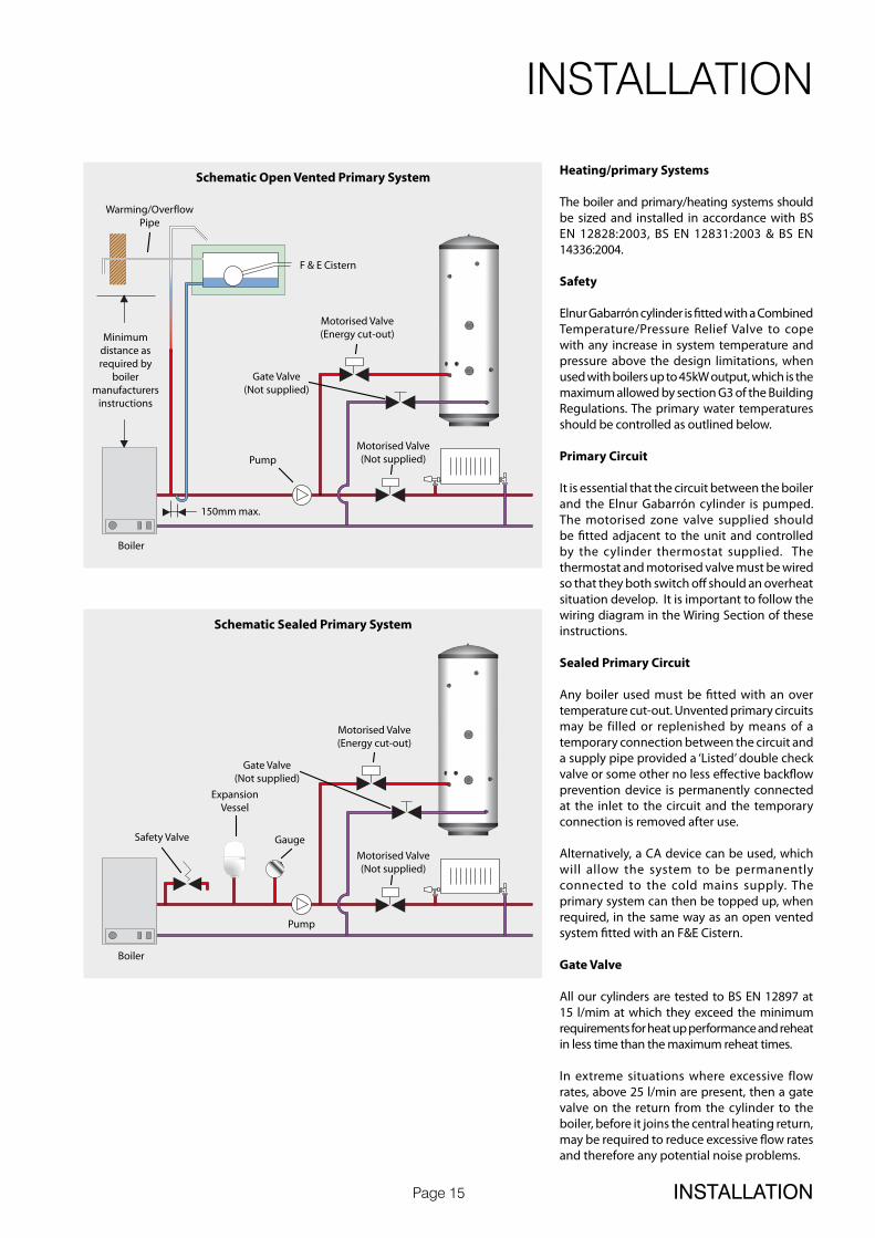
Heating/primary Systems
The boiler and primary/heating systems should be sized and installed in accordance with BS EN 12828:2003, BS EN 12831:2003 & BS EN 14336:2004.
Safety
Elnur Gabarrón cylinder is fitted with a Combined Temperature/Pressure Relief Valve to cope with any increase in system temperature and pressure above the design limitations, when used with boilers up to 45kW output, which is the maximum allowed by section G3 of the Building Regulations. The primary water temperatures should be controlled as outlined below.
Primary Circuit
It is essential that the circuit between the boiler and the Elnur Gabarrón cylinder is pumped. The motorised zone valve supplied should be fitted adjacent to the unit and controlled by the cylinder thermostat supplied. The thermostat and motorised valve must be wired so that they both switch off should an overheat situation develop. It is important to follow the wiring diagram in the Wiring Section of these instructions.
Sealed Primary Circuit
Any boiler used must be fitted with an over temperature cut-out. Unvented primary circuits may be filled or replenished by means of a temporary connection between the circuit and a supply pipe provided a ‘Listed’ double check valve or some other no less effective backflow prevention device is permanently connected at the inlet to the circuit and the temporary connection is removed after use.
Alternatively, a CA device can be used, which will allow the system to be permanently connected to the cold mains supply. The primary system can then be topped up, when required, in the same way as an open vented system fitted with an F&E Cistern.
Gate Valve
All our cylinders are tested to BS EN 12897 at 15 l/mim at which they exceed the minimum requirements for heat up performance and reheat in less time than the maximum reheat times.
In extreme situations where excessive flow rates, above 25 l/min are present, then a gate valve on the return from the cylinder to the boiler, before it joins the central heating return, may be required to reduce excessive flow rates and therefore any potential noise problems.
Schematic Open Vented Primary System
Boiler
Pump
150mm max.
Warming/OverflowPipe
F & E Cistern
Minimumdistance asrequired by
boilermanufacturers
instructions
Motorised Valve(Not supplied)
Motorised Valve(Energy cut-out)
Gate Valve(Not supplied)
Schematic Sealed Primary System
Boiler
Motorised Valve(Energy cut-out)
ExpansionVessel
GaugeSafety Valve
Pump
Motorised Valve(Not supplied)
Gate Valve(Not supplied)
INSTALLATION
INSTALLATION

Page 16
Mixed HW out
Mains CW in
Figure 1: Cold port of the blending valve connected to mains supplyNOT ALLOWED
Mixed HW out
Mains CW in
Figure 3: Cold port of the blending valve connected to mains supplyto the vessel after the inlet control group
Mixed HW out
Mains CW in
Non-Return Valve (must be fitted)
Figure 2: Cold port of the blending valve connected to balanced coldsupply - NON-RETURN VALVE MUST BE FITTED
Fitting Blending Valves To The Unvented Elnur Gabarrón Appliances
When fitting a blending valve to the unvented appliances, it is important that the installation does not contravene the G3, WRC and Health and Safety directives or the manufacturers recommendations. If this is the case, then the warranty should be null & void. The key requirements to comply with these regulations are: -
1. Any fitting or material in contact with potable water (e.g. a blending valve) must be approved by WRC or an equivalent body.
2. Connections or wiring arrangements must not bypass any safety devices.
3. Any expansion due to heating must not be allowed to expand back into the cold mains.
4. The settings of any safety devices must not be tampered with or adjusted.
The diagrams opposite shows how the blending valve can be piped onsite.
Figure 1 shows the cold water port of the blending valve connected to the mains cold water supply before the inlet control group. This arrangement is completely unacceptable and illegal because: -• the water is allowed to expand in to mains
cold water supply.• the vessel will be charged to the incoming
mains supply which may be considerably higher than the working pressure of the vessel.
If this arrangement is used then the Elnur UK warrant will not be valid.
Figure 2 shows the cold water port of the blending valve connected to the balanced cold water outlet. This arrangement will only be acceptable if a WRAS approved non-return valve is fitted, otherwise: -• during the heating cycle, the water will
expand back into the mains supply, as the regulating valve must not be relied upon to act as a check valve under all operating conditions.
• depending upon the characteristics of the blending valve, hot water may also flow from the balanced cold water taps.
Figure 3 shows the cold port of the blending valve connected to the cold water supply to the vessel after the inlet control group. This should be the preferred method. It is recommended that the installer should ensure that there is no gravity circulation in the pipework connected to the cold port. If necessary, this can be achieved by fitting a non-return valve or using a thermal trap.
INSTALLATION
INSTALLATION
✗
Page 17
INSTALLATION
INSTALLATION
1 98765432 10 11 12
N L 1 2 3 4
OFF ON OFF ON
HW CH
1 2 3 4
Room ThermostatCentral Heating Control
C 1 C1 2
Dual Aqau Stat
Overheat Stat Control Stat
L N E
Mains SupplyFed Via DoublePole Isolator230 VAC ~ 5 Amps
DanfossWB12Wiring Centre
HTGVALVE
HWVALVE
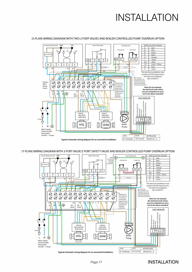
Typical schematic wiring diagram for an unvented installation
The electrical installation mustcomply with IEE requirements.
For electrical installationrefer to BS7671
Note: Do not attemptthe electrical work unless
you are competent to carryout to the above standard
BlueBlBrownBr
GreenGreyGreen / Yellow
GGrG/Y
WIRE COLOUR LEGEND
BlackOrangeYellowWhite
Red
BOrYWh
R
Br Bl G/Y Br Br Bl G/Y OrGr
5 Amps
Br Bl G/Y Br Br B *Br Bl G/Y
BrB
Bl Br Br Br
Br Bl BG/Y G/Y Br *Br
* Blue core used from standard 3 core flex please ensure you use brown sleeving at both terminating ends to identify core potential.
3 core flex4 core cable
L N
L L_P
SL_B
EN N_P
E_P
Br Bl G/Y B Br Bl G/YBoilerPump
ISSUE No : 5APPROVEDDRN. DATE
07-12-10N. Fursman
V4043ATWO PORTZONE VALVE
A BHTG
Br Bl G/Y OrGr
V4043ATWO PORTZONE VALVE
A BDHW
Br Bl G/Y Or Gr
GAS BOILER
Bo
iler P
erm
anen
t Li
ve
Bo
iler N
eutr
alB
oile
r Ear
th
Bo
iler S
wit
ch L
ive
Dem
and
Bo
iler C
on
tro
lled
Pu
mp
Provide extra corefrom terminal 12 toL-P connection onthe boiler (showndotted) and removethe boiler pump linkif the boiler has anindependantpump output.
L N E
(S-PLAN) WIRING DIAGRAM WITH TWO 2 PORT VALVES AND BOILER CONTROLLED PUMP OVERRUN OPTION
Br Bl G/Y
B BrOr
ELECTRONICS
1 98765432 10 11 12
N L 1 2 3 4
OFF ON OFF ON
HW CH
1 2 3 4
Room ThermostatCentral Heating Control
1C 22C 1
Dual Cylinder Stat
Overheat Stat
Spadeconnectors
requiredfor earth
connections
Control Stat
L N E
Mains SupplyFed Via DoublePole Isolator230 VAC ~ 5 Amps
HTGVALVE
HWVALVE
Typical schematic wiring diagram for an unvented installation
The electrical installation mustcomply with IEE requirements.
For electrical installationrefer to BS7671
Note: Do not attemptthe electrical work unless
you are competent to carryout to the above standard
BlueBlBrownBr
GreenGreyGreen / Yellow
GGrG/Y
WIRE COLOUR LEGEND
BlackOrangeYellowWhite
Red
BOrYWh
R
Br Bl G/Y Wh Br BrBl G/Y Or BGr Gr
5 Amps
Br Bl G/Y Br Br B *Br Bl G/Y
Bl Br Br Br
Br Bl BG/Y G/Y Br
R (Supplied with stat)
*BrB
* Blue core used from standard 3 core flex please ensure you use brown sleeving at both terminating ends to identify core potential.
4 core cable4 core cable
L N
L L_P
SL_B
EN N_P
E_P
Br Bl G/Y B Br Bl G/YBoilerPump
ISSUE No : 4APPROVEDDRN. DATE
07-12-10N. Fursman
A BHTG
Wh Bl G/Y OrGr
A BDHW
Br Bl G/Y Or Gr
GAS BOILER
Bo
iler P
erm
anen
t Li
ve
Bo
iler N
eutr
alB
oile
r Ear
th
Bo
iler S
wit
ch L
ive
Dem
and
Bo
iler C
on
tro
lled
Pu
mp
Provide extra corefrom terminal 12 toL-P connection onthe boiler (showndotted) and removethe boiler pump linkif the boiler has anindependantpump output.
L N E
(Y-PLAN) WIRING DIAGRAM WITH 3 PORT VALVE/2 PORT SAFETY VALVE AND BOILER CONTROLLED PUMP OVERRUN OPTION
Br Bl G/Y
B BBrOr
ELECTRONICS
13
V4073AMID POSITION
ZONE VALVE
V4043ATWO PORT
ZONE VALVE

Page 18
Connections can come loose in transit, and all should be checked before installation.
The control thermostat of the immersion heaters for direct heating of our cylinders are set at 60°C. The control thermostat for indirect heat exchanger heat up of our cylinders are usually set at between 60°C - 65°C. During commissioning the actual temperature that the cylinder reaches when the thermostat(s) operate should be tested and adjusted so that it achieves a minimum of 60°C. This temperature needs to be achieved on a regular basis.
Check the pressure on the air side of the expansion vessel = 3 bar. This must be done when the water in the cylinder is free to expand in atmospheric pressure or the cylinder and relevant pipe work is empty.
Check that the drain cock is closed, and open all the cold and hot water taps and other terminal fittings. Allow the system to fill with water, and to run until there is no air left in the system. Close the taps and inspect the system closely for leaks.
Manually open the Relief Valves one by one and check that water is discharged and run freely through the tundish and out at the discharge point. The pipework should accept full bore discharge without overflowing at the tundish, and the valve should seat satisfactorily.
In line with good plumbing practice, use with excessive flux should be avoided. When soldering above the cylinder, ensure flux/solder does not contaminate the cylinder below, since this can cause corrosion. Flushing should be done performed as per BS EN 806:4 2010 section 6.2.
Allow the cylinder to heat to normal working temperature, then thoroughly flush the domestic hot and cold water pipework through each tap.
NOTE: If this appliance is to be installed in other than a single domestic dwelling ie. in an apartment block or student flats etc., the hot and cold water system will need to be disinfected in accordance with BS EB 806:4 2010 section 6.3 and the Water Regulations.
Because the Elnur Gabarrón cylinder appliance is stainless steel, the use of chlorine as the disinfection agent can cause damage unless the appliance is adequately flushed and refilled with the mains water immediately on completion of the disinfection procedure.
Damage caused through a failure to do this adequately will not be covered by the warranty.
For the reasons mentioned, we recommend the use of a non chlorine based disinfectant such as Fernox LP Sterox as manufactured by Cookson Electronics when carrying out disinfection of systems incorporating these appliances.
Remove the filter from the combination inlet group clean and replace. Refill the system and open all hot taps until there is no air in the pipe work. ENSURE CYLINDER IS DRAINED PRIOR TO CHECKING OR REMOVING FILTER FROM THE COMBINATION INLET GROUP.
Allow the cylinder to heat to normal working temperature with whatever heat source is to be used, and check again for leaks. The pressure relief valve or the P&T valve should not operate during the heating cycle. If the P&T valve operates before the pressure relief valve due to high pressure, check that the inlet control group is fitted correctly.
The boiler/heating systems should be filled and commissioned in accordance with good practice following the guidance in BS 7593:2006/the boiler manufacturers instructions. This includes adequately flushing the system to remove any debris that may have been introduced during installation/maintenance.
NOTE
At the time of commissioning, complete all relevant sections of the Benchmark Checklist located on the inside back pages of this document.
This must be completed during commissioning and left with the product to meet the Warranty conditions offered by Elnur UK.
IMPORTANT - DRAIN DOWN PROCEDURE
1 Switch off both the boiler and the immersion heater
2 Open the nearest hot tap and run all hot water until cold, then close it
3 Close the incoming cold main at the stop tap
4 Hold open the pressure and temperature relief valve until water stops discharging into the tundish and leave it open
5 Open the cold taps starting from the highest point and working down to the lowest tap, leaving them open
6 When the cold taps have stopped draining, open the hot taps starting from the highest and working down to the lowest tap
7 Open the drain cock and ensure the pressure and temperature relief valve is held open until the cylinder is empty
INSTALLATION
COMMISSIONING

Page 19
Your Elnur Gabarrón unvented cylinder is automatic in normal use, but requires routine maintenance which is normally carried out at least annually along with the boiler service. The maintenance must be carried out by a suitably competent tradesperson who is qualified to work on unvented cylinders. The checks/work needed are listed in the maintenance part of these Instructions.
The control thermostat of the immersion heaters for direct heating of our cylinders are set at 60°C. The control thermostat for indirect heat exchanger heat up of our cylinders are usually set at between 60°C - 65°C. During commissioning the actual temperature that the cylinder reaches when the thermostat(s) operate should be tested and adjusted so that it achieves a minimum of 60°C, in order to comply with the Legionella pasteurisation requirements.
When initially opening the taps, a small surge in flow may be experienced, which disappears as the pressure in the system stabilises. This is quite normal with these types of systems and does not indicate a fault.
In some areas the water will initially appear cloudy, but will quickly clear when left to stand. This is nothing to be concerned about and is due to aeration of the water.
WARNING - If water is seen flowing through the tundish, this indicates a fault condition which needs action.
If the discharge is hot and continuous, turn the boiler and/or the immersion heaters off, but do not turn off the cold water to the appliance until the discharge is cold. Note: The discharge may stop by itself as the discharge cools.
If the discharge is cold and intermittent, no immediate action is needed but this indicates a problem with the expansion vessel.
However, in both cases you must call the registered installer / a suitably qualified, competent tradesperson, advise them that you have an unvented cylinder and request a maintenance visit.
DO NOT, at any time, tamper in any way with the safety valves or overheat thermostats/wiring.
INSTALLATION
USER INSTRUCTIONS
Page 20
The Registered Installer is responsible for the safe installation and operation of the system. The installer must also make his customer aware that periodic maintenance of the equipment is essential for safety.
Maintenance periods will vary for many reasons. Elnur UK Ltd recommend a maximum of 12 months to coincide with boiler maintenance. Experience of local water conditions may indicate that more frequent maintenance is desirable, eg, when water is particularly hard, scale-forming or where the water supply contains a high proportion of solids, eg, sand. Maintenance must include the following:
1. Check and clean filter2. Manually check the operation of the temperature relief valve.3. Manually check the operation of the expansion relief valve.4. Check discharge pipes from temperature and expansion relief valves are free from
obstruction and blockage and are not passing any water.5. Check the condition and if necessary descale the heat exchangers in hard water
areas.6. Check that water pressure downstream of pressure reducing valve is within the
manufacturers limits.7. Check operation of motorised valve.8. Check the pressure on the air side of the expansion vessel. This must be done
when the volume in the cylinders is cold.9. Check and advise the householder not to place any clothing or other combustible
materials against or on top of this appliance.10. On completion of the work, fill in the Benchmark Service Record towards the back
of this manual.
After servicing, complete the relevant Service Interval Record section of the Benchmark Checklist located on the inside back pages of this document.
IMPORTANT NOTE
When draining down the appliance for any reason, the instructions provided in the Commissioning Section (Page 18) MUST be followed to prevent potential damage to the cylinder.
SERVICING AND MAINTENANCE
SERVICING AND MAINTENANCE
Page 21
Scale
In hard water areas it is recommended that an in-line scale inhibitor is fitted. Reducing the temperature of the stored water will reduce the rate at which scale forms. If the recovery rate is badly affected, this is an indication that scaling may have occurred. In this event, follow the procedures as recommended by a reputable Water Treatment Company.
General
No water at the tap. Check that the mains water supply is turned ON. Check the line strainer is not blocked. Check that the combination valve has been fitted so that water is flowing in the correct direction.If the water at the tap is cold, ensure that the boiler has been switched ON and is working correctly. Check that there are no air locks in the primary system. ISOLATE THE UNIT AT THE MAINS ELECTRIC SUPPLY AND THEN CHECK THE FOLLOWING:i. The cylinder thermostatii. The thermal cut-out, which can be re-set by pushing the red buttoniii. The motorised valveiv. The boiler thermostatv. The boiler thermostat cut-out (if fitted)
ANY ENERGY CUT-OUT MUST NEVER BE BY-PASSED UNDER ANY CIRCUMSTANCES.
If the units are not getting hot and the heat source is electrical, ensure that the immersion heaters are isolated from the mains before re-setting the energy cut-out. If the immersion heater(s) need replacing this should be done with the units supplied from Elnur UK Limited.
Discharge From Relief Valves
If cold water is discharging from the expansion relief valve into the tundish check the pressure on the expansion vessel when cold and recharge if necessary.
If the fault continues and the problem cannot be stopped by operating the easing control a few times then either the Pressure Reducing Valve or the Relief Valve may be at fault. If the cold water pressure is too high, this would suggest that the Pressure Reducing Valve is at fault and the Elnur UK approved replacement should be fitted. If the pressure is correct then the Relief Valve will require replacing with a Elnur UK approved component.
See Commissioning for drain down procedure.
If there is an overheat fault and very hot water is being discharged, turn off the heat source, but not the water supply.
When the supply is cool, check thermostats and energy cut-outs in the boiler and immersion heaters and replace the faulty component with a unit supplied by Elnur UK and check that it works correctly before returning the system to full operation.
SERVICING AND MAINTENANCE
FAULT FINDING

Page 22
FAULT - No Hot Water (Direct)
FAULT - No Hot Water (Indirect)
Switch on
Re-set
Replace element
START
Is power on to elements?
Is control temperatureset at 60ºC - 65ºC?
Has high limit tripped?
Check wiring linkscontinuity and Re-set
END
YES
YES
YES
NO
NO
NO
Switch on
Set programmer
Re-set, check wiring &plumbing is correct
Re-set
Is all wiring to thecontrols ok?
Replace thermostat
Re-wire
START
Is boiler on?
Is hot water programmerin ‘on’ position?
Is zone valve incorrect position?
Is control temperatureset at 60ºC - 65ºC?
Has high limit cut out?
Re-set
END
YES
YES
YES
YES
YES
YES YES
NO
NO
NO
NO
NO NO
NO
SERVICING AND MAINTENANCE
FAULT FINDING

Page 23
FAULT - Poor Water Flow at Hot Taps
FAULT - Water Discharge Into Tundish
Water service check bysupply company required
Clean or replace straineras appropriate
Service /replace PRVas appropriate
START
END
Is incoming mains supplyflow/pressure adequate?
Is in-line strainer(in combination valve)
clean?
YES
YES
YES
YES
NO
NO
NO
Clear obstructionsIs system free from
restrictions/blockages?
YES
NO
Is pressure reducing valve(in combination valve)
working?
Clean or replaceas required
Is expansion vesselcharge pressure correct?
Replace ERV/TPRV
Replace PRV END
START
Is pressure downstreamof pressure reducing valve
correct?
Is valve seal and seatclean & undamaged?
Is heater operating atless than 60ºC?
Re-set temperature
NO
YES
YES
NO
NO
YES
YES
Is ERV/TPRVdischarging?
YES
Recommissionexpansion
vessel pressure
NO
NO
SERVICING AND MAINTENANCE
FAULT FINDING
Page 24
SERVICING AND MAINTENANCE
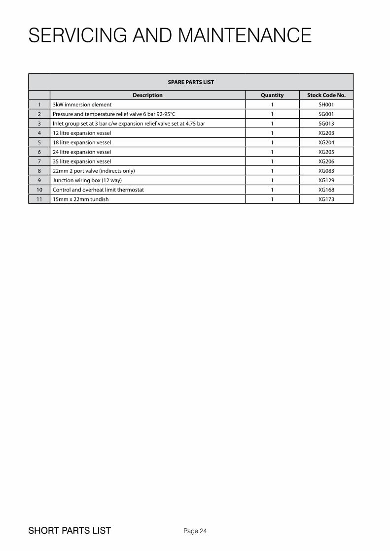
SHORT PARTS LIST
SPARE PARTS LIST
Description Quantity Stock Code No.
1 3kW immersion element 1 SH001
2 Pressure and temperature relief valve 6 bar 92-95°C 1 SG001
3 Inlet group set at 3 bar c/w expansion relief valve set at 4.75 bar 1 SG013
4 12 litre expansion vessel 1 XG203
5 18 litre expansion vessel 1 XG204
6 24 litre expansion vessel 1 XG205
7 35 litre expansion vessel 1 XG206
8 22mm 2 port valve (indirects only) 1 XG083
9 Junction wiring box (12 way) 1 XG129
10 Control and overheat limit thermostat 1 XG168
11 15mm x 22mm tundish 1 XG173

Page 25
Vast quantities of water are needlessly run off to waste due to Taps, Mixers and Showers discharging flow rates far in excess of the rates required for them to perform their duties.
The contrasting flow rates shown on this leaflet clearly illustrate the savings that can be made whilst still providing a good performance.
British made Aquaflow Regulators provide constant flow rates by automatically compensating for supply pressure changes between 1 bar & 10 bars.
To facilitate installation into the wide range of plumbing equipment which is encountered in the U.K, Four Fixing Options are available:-
Options For Showers
1. MXF “DW” Range - For fitting behind Fixed Shower Heads or onto Flexible Hoses for Handshowers (preferably onto the inlet end when lightweight hoses are used).
2. Compression Fitting Range. “In Line” regulators as in Option 4 for Taps & Mixers.
Information by courtesy of
AQUAFLOW REGULATORS LTDHaywood House, 40 New Road, Stourbridge, West Midlands DY8 1PA
TELEPHONE (01384) 442611 FAX: (01384) 442612
Water Savings
Water Related Costs Can Be Reduced By Good Plumbing Practice
TAPS & MIXERS
SHOWERS
Unregulated25 - 30 l/m
Regulated10 - 12 l/m
Over20 l/m
5, 6 or8 l/m
2 taphalf open
Fitted with regulatorUnregulated
4 Fixing Options For Taps & Mixers
1. MK Range - Combined Regulators & Aerator for screwing onto Taps & Mixers with internal or external threads on their noses. Anti Vandal models also available.
2. MR05-T Range - Internal Regulators. Push-fit into Tap or Mixer seats. Produced in three sizes - 12.5mm (BS1010), 12mm & 10mm, Flangeless models also available for Taps with Low Lift washers.
3. MXF Standard Range - Screw on tail models for Taps & Mixers. Fix onto the tails
before fitting the tap connectors. Available in 3/8", 1/2", 3/4" and 1" BSP.
4. Compression Fitting Range - “In Line” regulators housed in 15mm & 22mm CXC Couplers & Isolating Valves. “ ”UK WFBS listed by the Water Research Centre. Isolation valves available for slotted screwdriver operation or with coloured plastic handles. Now available also in plastic bodied push-fit couplers & valves.
2
1
1
2
1
2
3
3
1
4
APPENDIX
APPENDIX A

Page 26
Description
Manual handling means any transporting or supporting of a load (including lifting, putting down, pushing, pulling, carrying or moving) by hand or bodily force.
Scope
This assessment will cover the largest unit within each product range manufactured by Gledhill.
For specific weights and dimensions please refer to technical data section.
Main Hazards
Vision may not be clear due to the size of the products.Adopting an incorrect method of lifting may cause injury, attempting to lift these products will require help from others. (Team lifts)
Control Measures
Manual lifting procedure
The lift, key factors in safe lifting are:
a. Balanceb. Position of backc. Positioning of the arms and bodyd. The holde. Taking the lead for team lifts
a. Balance - Since balance depends essentially upon the position of the feet, they should be apart about hip breadth with one foot advanced giving full balance sideways and forward without tension. In taking up this position, lifting is done by bending at the knees instead of the hips and the muscles that are brought into use are those of the thigh and not the back.
b. Position of back - Straight - not necessary vertical. The spine must be kept rigid, this coupled with a bent knee position, allows the centre line of gravity of the body to be over the weight so reducing strain.
c. Positioning of arms and body - The further arms are away from the side, the greater the strain on the shoulders, chest and back. Keep elbows close to the body arms should be straight.
d. The hold - Before lifting ensure you have a good hold.
e. Taking the lead for team lifts- As more than one person is required for these products ensure that one person is taking the lead. This may be you so ensure that each person that is helping is made aware of the weight and of the items listed within this assessment. Make sure you and any others helping know the route you intend to take that it is clear of any obstructions. Never jerk the load as this will add a little extra force and can cause severe strain to the arms, back and shoulders. If there are steps involved decide on where you will stop and take a rest period. Move smoothly and in unison taking care to look and listen to others helping with the lift. Where possible use a sack truck to move the product over long flat distances, only lift the products when necessary. If in doubt stop and get more help.
Individual capability
Individual capability plays an important part in handling these products. Persons above average build and strength will find it easier and should be in good health. Persons below average build and strength may require more rest periods during the handling process.
Pregnant women should not carry out this operation.
Persons who are not in good health should seek medical advice prior to commencing any lifting or manual handling operation.
Residual risk
Following the guidelines given above will reduce any risk to injury.
All persons carrying out this operation must be fully trained and copies of the specific risk assessment made available for inspection and use in their training process.
Further guidance on Manual Handling can be obtained from the Health and Safety Executive. Manual Handling Operations Regulations 1992.
MANUAL HANDLING OF APPLIANCE PRODUCTS
APPENDIX
APPENDIX B

Page 27 NOTES
Page 28TERMS AND CONDITIONS

Page 29 TERMS AND CONDITIONS

Page 30BENCHMARK
This Commissioning Checklist is to be completed in full by the competent person who commissioned the storage system as a means of demonstrating compliance with the appropriate Building Regulations and then handed to the customer to keep for future reference.
Failure to install and commission this equipment to the manufacturer’s instructions may invalidate the warranty but does not affect statutory rights.
MAINS PRESSURE HOT WATER STORAGE SYSTEM COMMISSIONING CHECKLIST
Customer name: Telephone number:
Address:
Cylinder Make and Model
Cylinder Serial Number
Commissioned by (PRINT NAME): Registered Operative ID Number
Company name: Telephone number:
Company address:
Commissioning date:
To be completed by the customer on receipt of a Building Regulations Compliance Certificate*:
Building Regulations Notification Number (if applicable)
ALL SYSTEMS PRIMARY SETTINGS (indirect heating only)
Is the primary circuit a sealed or open vented system? Sealed Open
What is the maximum primary flow temperature? °C
ALL SYSTEMS
What is the incoming static cold water pressure at the inlet to the system? bar
Has a strainer been cleaned of installation debris (if fitted)? Yes No
Is the installation in a hard water area (above 200ppm)? Yes No
If yes, has a water scale reducer been fitted? Yes No
What type of scale reducer has been fitted?
What is the hot water thermostat set temperature? °C
What is the maximum hot water flow rate at set thermostat temperature (measured at high flow outlet)? I/min
Time and temperature controls have been fitted in compliance with Part L of the Building Regulations? Yes
Type of control system (if applicable) Y Plan S Plan Other
Is the cylinder solar (or other renewable) compatible? Yes No
What is the hot water temperature at the nearest outlet? °C
All appropriate pipes have been insulated up to 1 metre or the point where they become concealed Yes
UNVENTED SYSTEMS ONLY
Where is the pressure reducing valve situated (if fitted)?
What is the pressure reducing valve setting? bar
Has a combined temperature and pressure relief valve and expansion valve been fitted and discharge tested? Yes No
The tundish and discharge pipework have been connected and terminated to Part G of the Building Regulations Yes
Are all energy sources fitted with a cut out device? Yes No
Has the expansion vessel or internal air space been checked? Yes No
THERMAL STORES ONLY
What store temperature is achievable? °C
What is the maximum hot water temperature? °C
ALL INSTALLATIONS
The hot water system complies with the appropriate Building Regulations Yes
The system has been installed and commissioned in accordance with the manufacturer’s instructions Yes
The system controls have been demonstrated to and understood by the customer Yes
The manufacturer’s literature, including Benchmark Checklist and Service Record, has been explained and left with the customer Yes
Commissioning Engineer’s Signature
Customer’s Signature
(To confirm satisfactory demonstration and receipt of manufacturer’s literature)
* All installations in England and Wales must be notified to Local Authority Building Control (LABC) either directly or through a Competent Persons Scheme. A Building Regulations Compliance Certificate will then be issued to the customer.
© Heating and Hotwater Industry Council (HHIC) www.centralheating.co.uk
While this Checklist can be used for any installation covered by its description, only appliances manufactured by Scheme Members will be covered by the rules and requirements of the Benchmark Scheme.
Page 31 BENCHMARK
It is recommended that your hot water system is serviced regularly and that the appropriate Service Record is completed.
Service Provider
Before completing the appropriate Service Record below, please ensure you have carried out the service as described in the manufacturer’s instructions.
SERVICE RECORD
SERVICE 01 Date:
Engineer name:Company name:Telephone No:Comments:
Signature
SERVICE 03 Date:
Engineer name:Company name:Telephone No:Comments:
Signature
SERVICE 05 Date:
Engineer name:Company name:Telephone No:Comments:
Signature
SERVICE 07 Date:
Engineer name:Company name:Telephone No:Comments:
Signature
SERVICE 09 Date:
Engineer name:Company name:Telephone No:Comments:
Signature
SERVICE 02 Date:
Engineer name:Company name:Telephone No:Comments:
Signature
SERVICE 04 Date:
Engineer name:Company name:Telephone No:Comments:
Signature
SERVICE 06 Date:
Engineer name:Company name:Telephone No:Comments:
Signature
SERVICE 08 Date:
Engineer name:Company name:Telephone No:Comments:
Signature
SERVICE 10 Date:
Engineer name:Company name:Telephone No:Comments:
Signature
Due to a programme of continuous improvement Elnur UK reserve the right to modify products without prior notice.It is advisable to check the product technical detail by using the latest design and installation manuals available from our technical support team or on our website.
It is an offence to copy or adapt this document without consent of the owner.
ELNUR UK LimitedUnit 1, Brown Street North
Leigh, LancashireWN7 1BU
Tel.: 01942 670119Fax: 01942 [email protected]