Embed Size (px)
Citation preview
PRE-PLUMBED UNVENTED MAINS PRESSURE WATER HEATER120, 150, 170, 210, 250 and 300 LITRE CAPACITY INDIRECT MODELS
INSTALLATION AND SERVICING INSTRUCTIONS
IMPORTANT: PLEASE READ AND UNDERSTAND THESE INSTRUCTIONS BEFORE COMMENCING INSTALLATION. PLEASE LEAVE THIS MANUAL
WITH THE CUSTOMER FOR FUTURE REFERENCE.
CONTENTS
INTRODUCTION .................................................................................................................................3
GENERAL REQUIREMENTS...................................................................................................................4
INSTALLATION – GENERAL..................................................................................................................9
INSTALLATION - DISCHARGE .............................................................................................................12
INSTALLATION - PRIMARY CIRCUIT ....................................................................................................15
COMMISSIONING .............................................................................................................................18
MAINTENANCE ..................................................................................................................................19
USER INSTRUCTIONS .........................................................................................................................20
FAULT FINDING & SERVICING ............................................................................................................22
SPARE PARTS ......................................................................................................................................23
GUARANTEE ......................................................................................................................................25
ENVIROMENTAL INFORMATION.........................................................................................................25
COMMISSIONING CHECK LIST ..........................................................................................................26
SERVICE RECORD ...............................................................................................................................27
TECHNICAL SUPPORT ........................................................................................................................28
THE BENCHMARK SCHEMEBenchmark places responsibilities on both manufacturers and installers. The purpose is to ensure that customers are provided with the correct equipment for their needs, that it is installed, commissioned and serviced in accordance with the manufacturer’s instructions by competent persons and that it meets the requirements of the appropriate Building Regulations. The Benchmark Checklist can be used to demonstrate compliance with Building Regulations and should be provided to the customer for future reference.
Installers are required to carry out installation, commissioning and servicing work in accordance with the Benchmark Code of Practice which is available from the Heating and Hotwater Industry Council who manage and promote the scheme. Visit www.centralheating.co.uk for more information.
IMPORTANT NOTE TO USER: PLEASE REFER TO THE USER INSTRUCTIONS SECTION ON PAGE 20 FOR IMPORTANT INFORMATION WITH RESPECT TO THE BENCHMARK SCHEME
2
INTRODUCTION
The PremierPlus SystemFit is a factory pre-plumbed and wired PremierPlus unvented water heater. The PremierPlus SystemFit is manufactured in the UK from top quality materials and meets all the latest relevant safety and constructional standards. The high grade Duplex stainless steel cylinder offers exceptional strength and corrosion resistance which is backed by a 30 year guarantee (see terms and conditions on page 25). Its performance, control system and insulation levels exceed the latest requirements of Building Regulation Part L.
The PremierPlus SystemFit unvented water heater can be fed directly from the cold water mains supply to the property without the need for separate feed cisterns or vent pipes. It is supplied fitted with all its necessary inlet and safety controls for compliance with Building Regulations. Also fitted are a primary circulating pump, automatic bypass valve, a flow balancing valve, 2 x 2 port motorised valves, primary filling loop and pressure gauge, a cylinder thermostat, thermal cut-out and wiring centre. The pump, motorised valves and thermal controls are supplied pre-wired. A heating and domestic hot water programmer, room temperature sensor, primary expansion vessel, automatic air vent and primary expansion relief valve are supplied loose for installation at a convenient position within the property. An electric immersion heater is also fitted to enable the unit to be heated should the boiler be turned off.
The PremierPlus SystemFit primary circuit can be connected to a variety of gas or oil fired boiler types, either open vented or sealed system. It is not recommended for use with “system” boilers as these already incorporate their own circulating pump and controls.
NOTE: If using a sealed heating system, adequate provision for expansion within the primary circuit MUST be provided by fitting the primary circuit expansion vessel supplied. Primary circuit expansion cannot be accommodated within the PremierPlus SystemFit. Ensure the primary circuit expansion relief valve (supplied) is fitted to the primary circuit.
The safety valves fitted to the PremierPlus SystemFit protect the water heater only. Failure to provide adequate primary system pressure relief when using a sealed heating system will invalidate the boiler manufacturer’s warranty. Consult the boiler manufacturer’s installation instructions for further advice.
3
GENERAL REQUIREMENTS
IMPORTANT: THIS APPLIANCE CAN BE USED BY CHILDREN AGED FROM 8 YEARS AND ABOVE AND PERSONS WITH REDUCED PHYSICAL SENSORY OR MENTAL CAPABILITIES OR LACK OF EXPERIENCE AND KNOWLEDGE IF THEY HAVE BEEN GIVEN SUPERVISORY OR INSTRUCTION CONCERNING USE OF THE APPLIANCE IN A SAFE WAY AND UNDERSTAND THE HAZARDS INVOLVED. CHILDREN SHALL NOT PLAY WITH THE APPLIANCE. CLEANING AND USER MAINTENANCE SHALL NOT BE MADE BY CHILDREN WITHOUT SUPERVISION.
WARNING: Do not switch on if there is a possibility that the water in the heater is frozen.
COMPONENT CHECK LIST
Before commencing installation check that all the components for your PremierPlus SystemFit unit are contained in the package. The following components are supplied with your PremierPlus Systemfit unit:
• Factory fitted immersion heater(s) and thermal controls• Cold water combination valve (comprises pressure reducing valve, strainer, check valve) (supplied loose)• Factory fitted expansion core unit (comprises expansion valve and check valve)• Potable water expansion vessel (supplied loose) factory fitted temperature/pressure relief valve (set at 90°C/10 bar)• Tundish • Factory fitted indirect thermostat and thermal cut-out• 2 x 2-port motorised valve • Primary circulating pump• Lock-shield flow balancing valve• Automatic bypass valve• Primary circuit filling loop• Primary circuit pressure gauge• Automatic air vent• Primary circuit expansion vessel (supplied loose)• CH/DHW programmer and room temperature sensor (supplied loose)
SITING THE UNIT
The PremierPlus SystemFit unit must be vertically floor mounted. It can be placed anywhere convenient provided the discharge pipe(s) from its safety valves can be correctly installed. Areas that are subject to freezing must be avoided. Ensure that the floor is of sufficient strength to support the “full” weight of the unit (table 1, page 5). Pipe runs should be kept as short as possible for maximum economy. Access to associated controls, immersion heaters and indirect controls should be possible for servicing and maintenance of the system.
To aid installation the PremierPlus SystemFit is provided with lifting points located in the base and top mouldings. A floor template is also provided to aid positioning.
If you choose to install the PremierPlus SystemFit in the highest point in the property (e.g. loft space), it is advisable to install an additional automatic air vent (AAV) (not supplied - available as spare, part number 95 605 050) above the pump to enable air to be removed from the system. The addition of the AAV is not required if siting the cylinder in a lower position.
WATER SUPPLY
Bear in mind that the water supply to the property will be supplying both the hot and cold water requirements simultaneously. It is recommended that the maximum water demand is assessed and the water supply checked to ensure this demand can be satisfactorily met.
NOTE: A high water pressure will not always guarantee high flow rates.
Wherever possible the PremierPlus Systemfit supply pipe should be 22mm. We suggest the minimum supply requirements should be 1.5 bar pressure and 20 litres per minute flow rate. However, at these values outlet flow rates may be poor if several outlets are used simultaneously. The higher the available pressure and flow rate the better the system performance.
The PremierPlus SystemFit cylinder has an operating pressure of 3.5 bar which is controlled by the cold water combination valve assembly. The cold water combination valve assembly can be connected to a maximum pressure of 16 bar.
4
OUTLET/TERMINAL FITTINGS (TAPS, ETC.)
The PremierPlus SystemFit can be used in conjunction with most types of terminal fittings, plumbing fittings and pipework. However, the rated pressures of any fittings selected should be checked for compatibility before installation.
NOTE: Accessories, plumbing fittings and pipework should have a rated operating pressure of at least 6 bar.Outlets situated higher than the PremierPlus SystemFit unit will give outlet pressures lower than that at the heater, a 10m height difference will result in a 1 bar pressure reduction at the outlet fitting.
LIMITATIONS
The PremierPlus SystemFit cylinder should not be used in association with any of the following:• Solid fuel boilers or any other boiler in which the energy input is not under effective thermostatic control, unless additional
and appropriate safety measures are installed.• Ascending spray type bidets or any other class 1 back syphonage risk require that a type A air gap be employed.• Steam heating plants unless additional and appropriate safety devices are installed.• Situations where maintenance is likely to be neglected or safety devices tampered with.• Water supplies that have either inadequate pressure or where the supply may be intermittent.• Situations where it is not possible to safely pipe away any discharge from the safety valves.• In areas where the water consistently contains a high proportion of solids, e.g. suspended matter that could block the
strainer unless adequate filtration can be ensured.
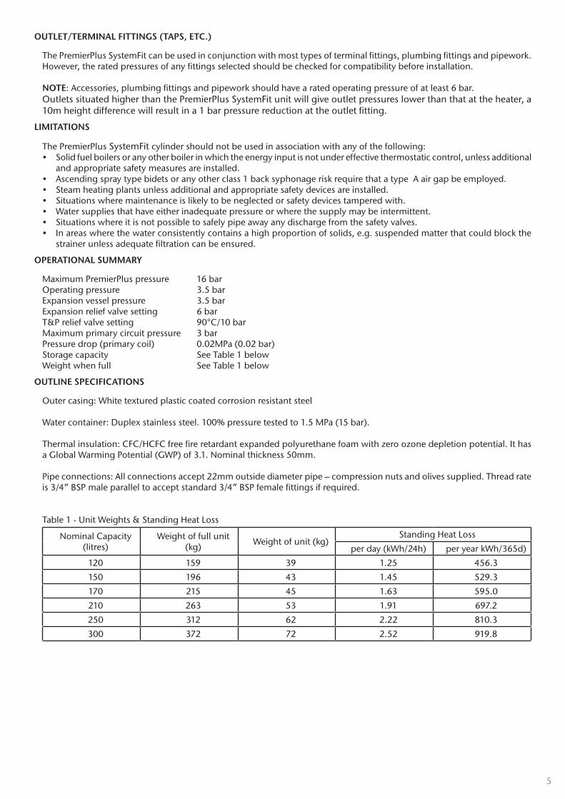
OPERATIONAL SUMMARY
Maximum PremierPlus pressure 16 barOperating pressure 3.5 barExpansion vessel pressure 3.5 barExpansion relief valve setting 6 barT&P relief valve setting 90°C/10 barMaximum primary circuit pressure 3 barPressure drop (primary coil) 0.02MPa (0.02 bar)Storage capacity See Table 1 belowWeight when full See Table 1 below
OUTLINE SPECIFICATIONS
Outer casing: White textured plastic coated corrosion resistant steel
Water container: Duplex stainless steel. 100% pressure tested to 1.5 MPa (15 bar).
Thermal insulation: CFC/HCFC free fire retardant expanded polyurethane foam with zero ozone depletion potential. It has a Global Warming Potential (GWP) of 3.1. Nominal thickness 50mm.
Pipe connections: All connections accept 22mm outside diameter pipe – compression nuts and olives supplied. Thread rate is 3/4” BSP male parallel to accept standard 3/4” BSP female fittings if required.
Table 1 - Unit Weights & Standing Heat Loss
Nominal Capacity (litres)
Weight of full unit (kg) Weight of unit (kg)
Standing Heat Loss
per day (kWh/24h) per year kWh/365d)
120 159 39 1.25 456.3
150 196 43 1.45 529.3
170 215 45 1.63 595.0
210 263 53 1.91 697.2
250 312 62 2.22 810.3
300 372 72 2.52 919.8
5
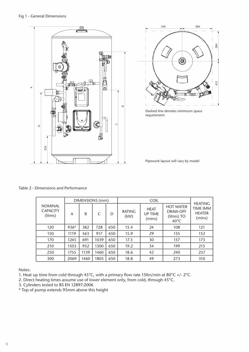
Fig 1 - General Dimensions
Table 2 - Dimensions and Performance
6
NOMINAL CAPACITY
(litres)
DIMENSIONS (mm) COILHEATING
TIME IMM HEATER (mins)
A B C D RATING (kW)
HEAT UP TIME (mins)
HOT WATERDRAW-OFF (litres) TO
40°C
120 936* 382 728 650 15.4 24 108 121
150 1119 563 917 650 15.9 29 135 152
170 1245 691 1039 650 17.3 30 157 173
210 1503 952 1300 650 19.2 34 199 215
250 1755 1139 1460 650 18.6 42 240 257
300 2069 1460 1805 650 18.8 49 273 310
Notes:1. Heat up time from cold through 45°C, with a primary flow rate 15ltrs/min at 80°C +/- 2°C.2. Direct heating times assume use of lower element only, from cold, through 45°C.3. Cylinders tested to BS EN 12897:2006* Top of pump extends 95mm above this height
340 284
284
412
A
B
C
D
256
Dashed line denotes minimum spacerequirement
Pipework layout will vary by model
Danfoss TP9000 Programmable thermostat with timed Domestic Hot Water (DHW) control:
Programmer dimensions: 135mm (W) x 88mm (H) x 32mm (D)Room temperature sensor dimensions: 60mm (W) x 45mm (H) x 21mm (D)Power supply: 220V/240V ac, 50HzSwitch action 2 x SPDT, Type 1B. Switch rating 220/240V ac, 50/60Hz, 3(1)APower reserve: Minimum 24 hoursMemory back up retained for life of product Enclosure rating: IP30Control temperature range: Selectable 5 to 30°CHoliday mode with room temperature setbackTiming accuracy: +/- 1 minute/monthMaximum ambient temperature: 45°C
Honeywell 2 Port motorised valves:
Model No.: V4043HVoltage rating: 230V ac, 50HZPower consumption: 6WPrimary water temperature range: 5 to 88°CMaximum ambient temperature: 52°C
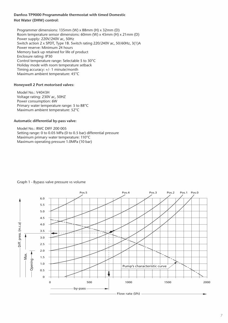
Automatic differential by-pass valve:
Model No.: RWC DIFF 200 005Setting range: 0 to 0.05 MPa (0 to 0.5 bar) differential pressure Maximum primary water temperature: 110°CMaximum operating pressure 1.0MPa (10 bar)
Graph 1 - Bypass valve pressure vs volume
7
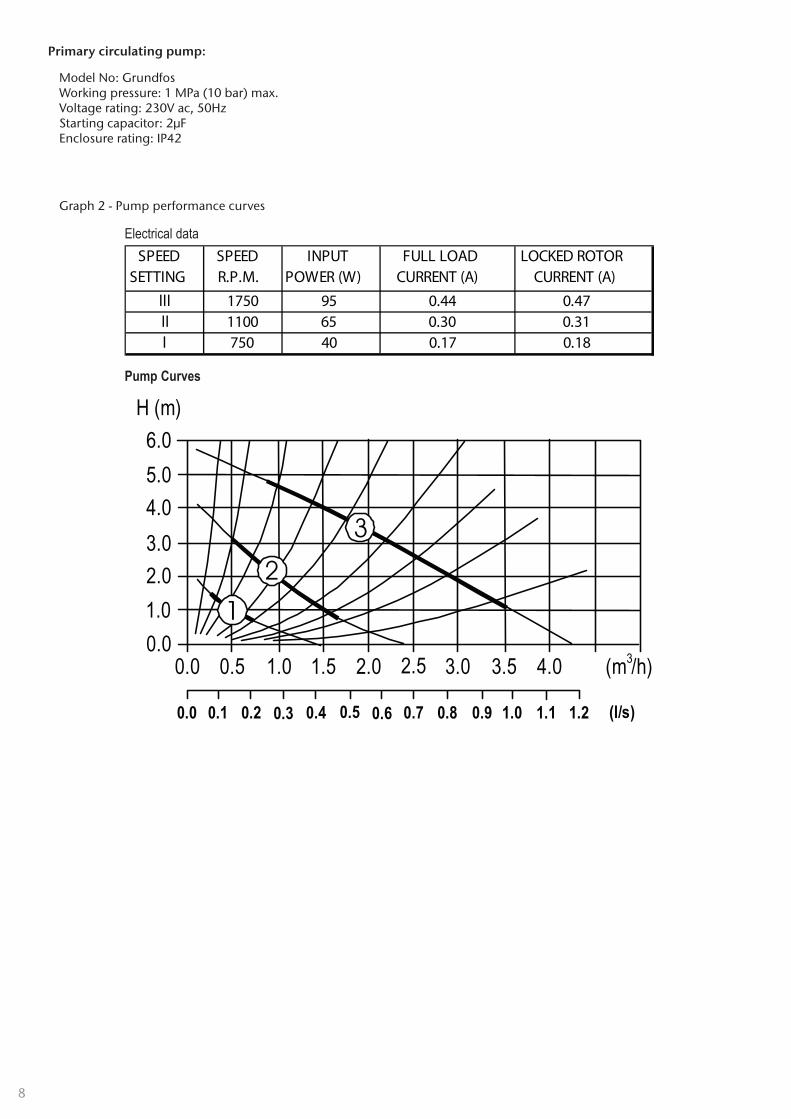
Primary circulating pump:
Model No: Grundfos Working pressure: 1 MPa (10 bar) max.Voltage rating: 230V ac, 50HzStarting capacitor: 2µFEnclosure rating: IP42
Electrical dataSPEED
SETTINGSPEED R.P.M.
INPUT POWER (W)
FULL LOAD CURRENT (A)
LOCKED ROTOR CURRENT (A)
lll 1750 95 0.44 0.47ll 1100 65 0.30 0.31l 750 40 0.17 0.18
1
3
2
0.00.0
0.0 0.1 0.2 0.3 0.4 0.5 0.6 0.7 0.8 0.9 1.0 1.1 1.2
0.5 2.5 3.0 3.5 4.02.01.51.0
1.02.03.04.05.06.0
H (m)
( /h)3m
(l/s)
Pump Curves
Graph 2 - Pump performance curves
8
INSTALLATION – GENERAL
PIPE FITTINGS
The connection points to the heating system are in 22mm copper pipe on 120, 150, 170 and 210 litre units. On units 250 litres and above the primary flow connection is 28mm, the flow connections to central heating (CH) zones 22mm and the domestic hot water (DHW) return connection 22mm copper pipe. The use of appropriately sized COMPRESSION FITTINGS is recommended when connecting to the PremierPlus SystemFit pipes. Solder fittings can be used, but extreme care must be taken to ensure the plastic coating of the unit casing is not damaged by heat. Push fit type fittings can be used for connection to the copper pipes.
The inlet connection to the cold water combination valve is 22mm compression. The PremierPlus SystemFit outlet fitting is suitable for connection to 22mm o/dia pipe (compression nut and olive supplied). The outlet is also threaded 3/4” BSP male parallel should threaded pipe connections be preferred.
COLD FEED
A 22mm cold water supply is recommended, however, if a 15mm (1/2”) supply exists which provides sufficient flow, this may be used. More flow noise may be experienced from small bore pipes due to the increased water velocity through them.
A stopcock or servicing valve should be incorporated into the cold water supply to enable the PremierPlus SystemFit and its associated controls to be isolated and serviced.
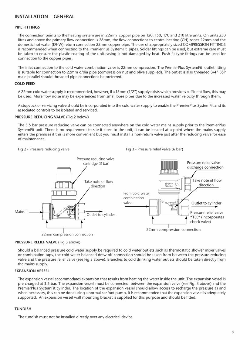
PRESSURE REDUCING VALVE (Fig 2 below)
The 3.5 bar pressure reducing valve can be connected anywhere on the cold water mains supply prior to the PremierPlus SystemFit unit. There is no requirement to site it close to the unit, it can be located at a point where the mains supply enters the premises if this is more convenient but you must install a non-return valve just after the reducing valve for ease of maintenance.
Fig 2 - Pressure reducing valve Fig 3 - Pressure relief valve (6 bar)
PRESSURE RELIEF VALVE (Fig 3 above)
Should a balanced pressure cold water supply be required to cold water outlets such as thermostatic shower mixer valves or combination taps, the cold water balanced draw off connection should be taken from between the pressure reducing valve and the pressure relief valve (see Fig 3 above). Branches to cold drinking water outlets should be taken directly from the mains supply.
EXPANSION VESSEL
The expansion vessel accommodates expansion that results from heating the water inside the unit. The expansion vessel is pre-charged at 3.5 bar. The expansion vessel must be connected between the expansion valve (see Fig. 3 above) and the PremierPlus SystemFit cylinder. The location of the expansion vessel should allow access to recharge the pressure as and when necessary, this can be done using a normal car foot pump. It is recommended that the expansion vessel is adequately supported. An expansion vessel wall mounting bracket is supplied for this purpose and should be fitted.
TUNDISH
The tundish must not be installed directly over any electrical device.
9
Outlet to cylinderMains in
22mm compression connection
Take note of flow direction
Pressure reducing valve cartridge (3 bar)
22mm compression connection
Outlet to cylinder
From cold watercombination valve
Take note of �ow direction
Pressure relief valvedischarge connection
Pressure relief valve“TEE” (incorporatescheck valve)
10
DRAIN TAPS
Drain taps are fitted to both the primary system pipework and to the cold water inlet to facilitate draining the unit or indirect heating circuit for maintenance purposes. It is recommended that the outlet point of the drain pipe work be at least 1 metre below the level of the heater (this can be achieved by attaching a hose pipe to the drain tap outlet spigot).
HOT WATER OUTLET
Ideally the pipework from the PremierPlus SystemFit to the outlet fittings should be in 22mm pipe with short runs of 15mm pipe to showers and basin taps. Small bore pipe can also be used to suit some taps, but runs should be of minimum length. Pipe sizes may vary due to system design.
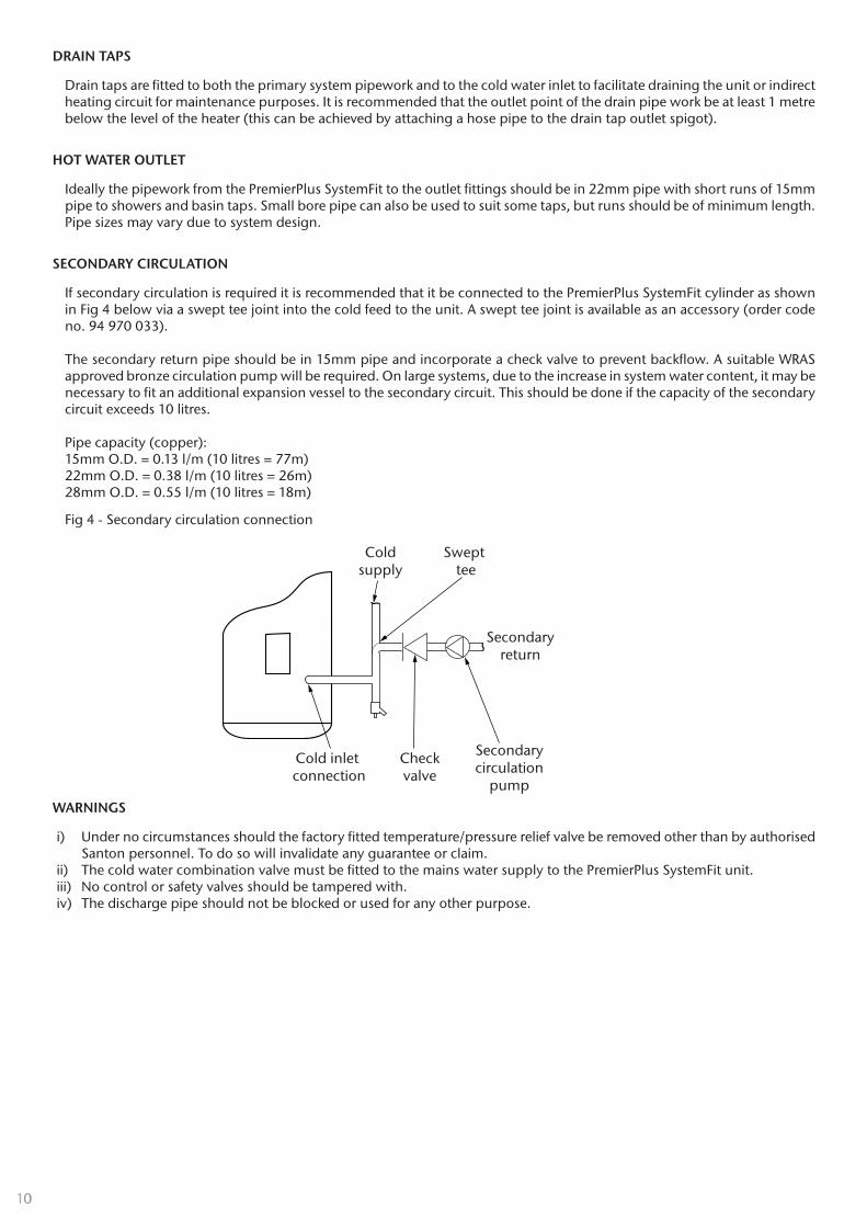
SECONDARY CIRCULATION
If secondary circulation is required it is recommended that it be connected to the PremierPlus SystemFit cylinder as shown in Fig 4 below via a swept tee joint into the cold feed to the unit. A swept tee joint is available as an accessory (order code no. 94 970 033).
The secondary return pipe should be in 15mm pipe and incorporate a check valve to prevent backflow. A suitable WRAS approved bronze circulation pump will be required. On large systems, due to the increase in system water content, it may be necessary to fit an additional expansion vessel to the secondary circuit. This should be done if the capacity of the secondary circuit exceeds 10 litres.
Pipe capacity (copper):15mm O.D. = 0.13 l/m (10 litres = 77m)22mm O.D. = 0.38 l/m (10 litres = 26m)28mm O.D. = 0.55 l/m (10 litres = 18m)
WARNINGS
i) Under no circumstances should the factory fitted temperature/pressure relief valve be removed other than by authorised Santon personnel. To do so will invalidate any guarantee or claim.
ii) The cold water combination valve must be fitted to the mains water supply to the PremierPlus SystemFit unit.iii) No control or safety valves should be tampered with.iv) The discharge pipe should not be blocked or used for any other purpose.
Cold inlet connection
Checkvalve
Secondarycirculation
pump
Swept tee
Coldsupply
Secondaryreturn
Fig 4 - Secondary circulation connection
11
Tund
ish
Bal
ance
d c
old
wat
er
dra
w-o
ff6
Bar
Pre
ssur
e R
elie
fVa
lve
(co
mb
ined
Exp
ansi
on
Rel
ief
Valv
e/C
heck
Val
ve)
3.5
Bar
Pre
ssure
Red
uci
ng
Val
ve in
corp
ora
ting
Pre
ssure
Red
uci
ng
Val
ve,
Str
ainer,a
nd
Check
Val
ve.
(Sto
p c
ock
can
be fi
tted
here
)
MC
WS t
o K
itch
en
(unb
alan
ced
co
ldm
ains
sup
ply
)
Inco
min
g C
old
Wat
er
Mai
n
KE
YM
CW
S =
M
ains
cold
wat
er
sup
ply
HW
S =
Ho
t w
ater
serv
ice
SC
=
Sto
p C
ock
/ Is
ola
ting
Val
veD
OC
=
Dra
in O
ff C
ock
Dis
char
ge p
ipe
to a
tmos
pher
e
Iso
lati
ng
/Reg
ula
ting
Val
ves,
as
req
uir
ed
Tem
pera
ture
/Pre
ssure
Relie
f Val
ve
HW
S su
pp
lyB
alan
ced
HW
S an
dM
CW
S to
bat
hro
om
s,sh
ow
ers,
clo
akro
om
s,et
c
DO
CD
OC
DO
C
DO
C
SC
SC
Pre
mie
rPlu
s S
yste
mFit
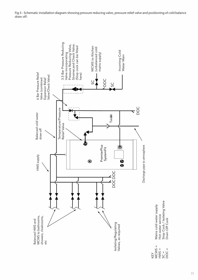
Fig 5 - Schematic installation diagram showing pressure reducing valve, pressure relief valve and positioning of cold balance draw off.
12
INSTALLATION - DISCHARGE
It is a requirement of Building Regulation G3 that any discharge from an unvented system is conveyed to where it is visible, but will not cause danger to persons in or about the building. The tundish and discharge pipes should be fitted in accordance with the requirements and guidance notes of Building Regulation G3. The G3 Requirements and Guidance section 3.50 - 3.63 are reproduced in the following sections of this manual. For discharge pipe arrangements not covered by G3 Guidance advice should be sought from your local Building Control Officer. Any discharge pipe connected to the pressure relief devices (Expansion Valve and Temperature/Pressure Relief Valve) must be installed in a continuously downward direction and in a frost free environment.
Water may drip from the discharge pipe of the pressure relief device. This pipe must be left open to the atmosphere. The pressure relief device is to be operated regularly to remove lime deposits and to verify that it is not blocked.
G3 REQUIREMENT“...there shall be precautions...to ensure that the hot water discharged from safety devices is safely conveyed to where it is visible but will not cause danger to persons in or about the building.”
Notes: Discharge pipe-work D2 can now be a plastic pipe but only pipes that have been tested to a minimum 110°C must be used.Discharge pipe D2 can now be plumbed into the soil stack but only soil stacks that can handle temperatures of 99°C or greater should be used.
The following extract is taken from the latest G3 Regulations
Discharge pipe D1
3.50 Safety devices such as temperature relief valves or combined temperature and pressure and pressure relief valves (see paragraphs 3.13 or 3.18) should discharge either directly or by way of a manifold via a short length of metal pipe (D1) to a tundish.
3.51 The diameter of discharge pipe (D1) should be not less than the nominal outlet size of the temperature relief valve.3.52 Where a manifold is used it should be sized to accept and discharge the total discharge form the discharge pipes connected to it.3.53 Where valves other than the temperature and pressure relief valve from a single unvented hot water system dischargeby way of the same manifold that is used by the safety devices, the manifold should be factory fitted as part of the hot water storage system unit or package.
Tundish3.54 The tundish should be vertical, located in the same space as the unvented hot water storage system and be fitted as close as possible to, and lower than, the valve, with no more than 600mm of pipe between the valve outlet and the tundish (Fig. 6 & Table 3, page 14).
Note: To comply with the Water Supply (Water Fittings) Regulations, the tundish should incorporate a suitable air gap.
3.55 Any discharge should be visible at the tundish. In addition, where discharges from safety devices may not be apparent, e.g. in dwellings occupied by people with impaired vision or mobility, consideration should be given to the installation of a suitable safety device to warn when discharge takes place, e.g. electronically operated.
Discharge pipe D23.56 The discharge pipe (D2) from the tundish should:
(a) have a vertical section of pipe at least 300mm long below the tundish before any elbows or bends in the pipework (see Diagram 1, G3), (Fig. 6, page 14); and(b) be installed with a continuous fall thereafter of at least 1 in 200.
3.57 The discharge pipe (D2) should be made of:(a) metal; or(b) other material that has been demonstrated to be capable of safely withstanding temperatures of the water discharged and is clearly and permanently marked to identify the product and performance standard (e.g. as specified in the relevant part of BS 7291).
3.58 The discharge pipe (D2) should be at least one pipe size larger than the nominal outlet size of the safety device unless its total equivalent hydraulic resistance exceeds that of a straight pipe 9m long, i.e. for discharge pipes between 9m and 18m the equivalent resistance length should be at least two sizes larger than the nominal outlet size of the safety device; between 18 and 27m at least 3 sizes larger, and so on; bends must be taken into account in calculating the flow resistance. (See Diagram 1, Table 1, G3), (Fig. 6 & Table 3, page 14) and the worked example.
13
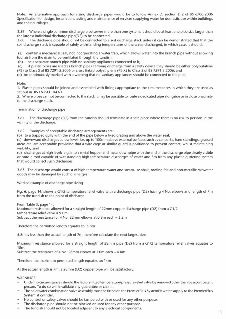
Note: An alternative approach for sizing discharge pipes would be to follow Annex D, section D.2 of BS 6700:2006 Specification for design, installation, testing and maintenance of services supplying water for domestic use within buildings and their curtilages.
3.59 Where a single common discharge pipe serves more than one system, it should be at least one pipe size larger than the largest individual discharge pipe(D2) to be connected.3.60 The discharge pipe should not be connected to a soil discharge stack unless it can be demonstrated that that the soil discharge stack is capable of safely withstanding temperatures of the water discharged, in which case, it should:
(a) contain a mechanical seal, not incorporating a water trap, which allows water into the branch pipe without allowing foul air from the drain to be ventilated through the tundish; (b) be a separate branch pipe with no sanitary appliances connected to it; (c) if plastic pipes are used as branch pipes carrying discharge from a safety device they should be either polybutalene (PB) to Class S of BS 7291-2:2006 or cross linked polyethylene (PE-X) to Class S of BS 7291-3:2006; and(d) be continuously marked with a warning that no sanitary appliances should be connected to the pipe.
Note: 1. Plastic pipes should be joined and assembled with fittings appropriate to the circumstances in which they are used as set out in BS EN ISO 1043-1.2. Where pipes cannot be connected to the stack it may be possible to route a dedicated pipe alongside or in close proximity to the discharge stack.
Termination of discharge pipe
3.61 The discharge pipe (D2) from the tundish should terminate in a safe place where there is no risk to persons in the vicinity of the discharge.
3.62 Examples of acceptable discharge arrangements are:(b) to a trapped gully with the end of the pipe below a fixed grating and above the water seal;(c) downward discharges at low level; i.e. up to 100mm above external surfaces such as car parks, hard standings, grassed areas etc. are acceptable providing that a wire cage or similar guard is positioned to prevent contact, whilst maintaining visibility; and(d) discharges at high level: e.g. into a metal hopper and metal downpipe with the end of the discharge pipe clearly visible or onto a roof capable of withstanding high temperature discharges of water and 3m from any plastic guttering system that would collect such discharges.
3.63 The discharge would consist of high temperature water and steam. Asphalt, roofing felt and non-metallic rainwater goods may be damaged by such discharges.
Worked example of discharge pipe sizing
Fig. 6, page 14: shows a G1/2 temperature relief valve with a discharge pipe (D2) having 4 No. elbows and length of 7m from the tundish to the point of discharge.
From Table 3, page 14:Maximum resistance allowed for a straight length of 22mm copper discharge pipe (D2) from a G1/2temperature relief valve is 9.0m.Subtract the resistance for 4 No. 22mm elbows at 0.8m each = 3.2m
Therefore the permitted length equates to: 5.8m
5.8m is less than the actual length of 7m therefore calculate the next largest size.
Maximum resistance allowed for a straight length of 28mm pipe (D2) from a G1/2 temperature relief valves equates to 18m.Subtract the resistance of 4 No. 28mm elbows at 1.0m each = 4.0m
Therefore the maximum permitted length equates to: 14m
As the actual length is 7m, a 28mm (D2) copper pipe will be satisfactory.
WARNINGS:• Under no circumstances should the factory fitted temperature/pressure relief valve be removed other than by a competent
person. To do so will invalidate any guarantee or claim.• The cold water combination valve assembly must be fitted on the PremierPlus SystemFit water supply to the PremierPlus
SystemFit cylinder.• No control or safety valves should be tampered with or used for any other purpose.• The discharge pipe should not be blocked or used for any other purpose.• The tundish should not be located adjacent to any electrical components.
14
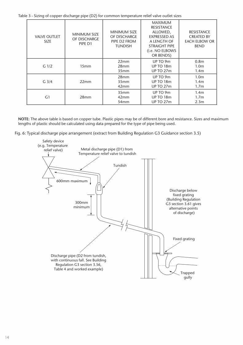
Table 3 - Sizing of copper discharge pipe (D2) for common temperature relief valve outlet sizes
600mm maximum
300mmminimum
Safety device(e.g. Temperature
relief valve) Metal discharge pipe (D1) from Temperature relief valve to tundish
Tundish
Discharge below �xed grating
(Building Regulation G3 section 3.61 gives
alternative points of discharge)
Fixed grating
Trapped gully
Discharge pipe (D2 from tundish,with continuous fall. See Building
Regulation G3 section 3.56,Table 4 and worked example)
VALVE OUTLET SIZE
MINIMUM SIZE OF DISCHARGE
PIPE D1
MINIMUM SIZE OF DISCHARGE PIPE D2 FROM
TUNDISH
MAXIMUM RESISTANCE ALLOWED,
EXPRESSED AS A LENGTH OF STRAIGHT PIPE
(i.e. NO ELBOWS OR BENDS)
RESISTANCE CREATED BY
EACH ELBOW OR BEND
G 1/2 15mm22mm28mm35mm
UP TO 9mUP TO 18mUP TO 27m
0.8m1.0m1.4m
G 3/4 22mm28mm35mm42mm
UP TO 9mUP TO 18mUP TO 27m
1.0m1.4m1.7m
G1 28mm35mm42mm54mm
UP TO 9mUP TO 18mUP TO 27m
1.4m1.7m2.3m
NOTE: The above table is based on copper tube. Plastic pipes may be of different bore and resistance. Sizes and maximum lengths of plastic should be calculated using data prepared for the type of pipe being used.
Fig. 6: Typical discharge pipe arrangement (extract from Building Regulation G3 Guidance section 3.5)
15
INSTALLATION - PRIMARY CIRCUIT
BOILER SELECTION
• The PremierPlus SystemFit models are suitable for use with most gas, oil fired or electric boilers compatible with unvented systems i.e. fitted with a temperature control thermostat and thermal cut-out.
• If in doubt consult the boiler manufacturer.• Solid fuel boilers or any other boiler in which the energy input is not under effective thermostatic control unless additional
and appropriate safety measures are installed should NOT be used.• The boiler used can either be a sealed system or open vented type, maximum primary circuit pressure 3 bar.• The primary flow from the boiler MUST be pumped. Gravity circulation will not work due to the special design of the
primary heat exchanger. • The boiler flow temperature should usually be set to 82°C (maximum flow temperature to primary heat exchanger
90°C).• The boiler cannot be vented through the PremierPlus SystemFit unit.
INDIRECT THERMAL CUT-OUT AND 2-PORT MOTORISED VALVE
To comply with Building Regulations and to prevent the PremierPlus SystemFit from overheating the 2-Port motorised valve supplied fitted to the primary flow to the indirect coil MUST NOT be removed or bypassed. This valve is factory wired in series with the indirect thermal cut-out such that the primary flow to the heating coil is interupted should the PremierPlus SystemFit unit overheat.
WIRING
All electrical wiring should be carried out by a competent electrician and be in accordance with the latest I.E.E. Wiring Regulations.
The PremierPlus SystemFit indirect thermostat and thermal cut-out, primary circulating pump and motorised valves are factory pre-wired. Further wiring will be required between the wiring centre, the programmer, room temperature sensor and the boiler (Fig 8, page 17). Additional controls and wiring will be required if a second CH zone is to be fitted to the instalation.
The indirect thermal cut-out MUST NOT be bypassed.
HEATING SYSTEM CONTROLS
The controls provided with the PremierPlus SystemFit will ensure the safe operation of the unit within a central heating system.
Connection to the various system components is made via the wiring centre fitted to the front of the PremierPlus SystemFit, refer to figure 8, page 17 and the terminal identification labels within the wiring centre to aid in connecting the various external system components such as the mains supply, programmer and boiler. The wiring to the external components is made using flexible cable, this should be secured using the integral cable grips located in the wiring centre.
Provision is made for the connection of a second CH zone (connection pipe supplied blanked off). Additional controls will be necessary to control the operation of the second CH zone, usually a second 28mm CH zone valve and a programmable room thermostat. Connection terminals are provided and identified in the wiring centre to enable any wiring to be connected to the same central position.
The mains supply must be via a double pole isolating switch with a contact separation of at least 3mm in both poles. The supply must be fused 3 amp. A supply cable of 1.0 to 1.5mm2 cross sectional area should be used.
16
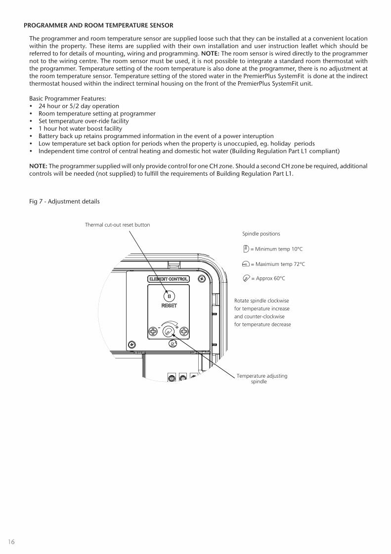
Fig 7 - Adjustment details
PROGRAMMER AND ROOM TEMPERATURE SENSOR
The programmer and room temperature sensor are supplied loose such that they can be installed at a convenient location within the property. These items are supplied with their own installation and user instruction leaflet which should be referred to for details of mounting, wiring and programming. NOTE: The room sensor is wired directly to the programmer not to the wiring centre. The room sensor must be used, it is not possible to integrate a standard room thermostat with the programmer. Temperature setting of the room temperature is also done at the programmer, there is no adjustment at the room temperature sensor. Temperature setting of the stored water in the PremierPlus SystemFit is done at the indirect thermostat housed within the indirect terminal housing on the front of the PremierPlus SystemFit unit.
Basic Programmer Features:• 24 hour or 5/2 day operation• Room temperature setting at programmer• Set temperature over-ride facility• 1 hour hot water boost facility• Battery back up retains programmed information in the event of a power interuption• Low temperature set back option for periods when the property is unoccupied, eg. holiday periods• Independent time control of central heating and domestic hot water (Building Regulation Part L1 compliant)
NOTE: The programmer supplied will only provide control for one CH zone. Should a second CH zone be required, additional controls will be needed (not supplied) to fulfill the requirements of Building Regulation Part L1.
Thermal cut-out reset button
Spindle positions
= Minimum temp 10°C
= Maximium temp 72°C
= Approx 60°C
Rotate spindle clockwise
for temperature increase
and counter-clockwise
for temperature decrease
Temperature adjusting spindle
17
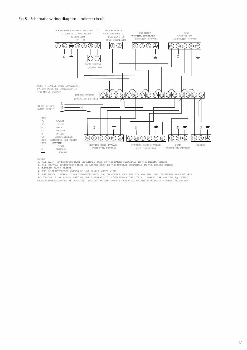
Fig 8 - Schematic wiring diagram - Indirect circuit
KEYBr BROWNBl BLUEG GREYO ORANGEW WHITEGY GREEN/YELLOWDHW DOMESTIC HOT WATERHTG HEATINGL LIVEN NEUTRAL EARTH
BOILER
(DHW) ZONE VALVE
WIRING CENTRE 1 2 3 4 5 6 7 8 9 10
L N
GBr Bl O GY21 3
L N
LN
PUMP
INDIRECTTHERMAL CONTROLS(SUPPLIED FITTED)
FUSED (3 AMP)MAINS SUPPLY
N.B. A DOUBLE POLE ISOLATINGSWITCH MUST BE INSTALLED IN THE MAINS SUPPLY
NOTES1. ALL EARTH CONNECTIONS MUST BE LINKED BACK TO THE EARTH TERMINALS IN THE WIRING CENTRE2. ALL NEUTRAL CONNECTIONS MUST BE LINKED BACK TO THE NEUTRAL TERMINALS IN THE WIRING CENTRE3. ASSUMES BASIC BOILER4. THE 22MM MOTORISED VALVES DO NOT HAVE A WHITE WIRE 5. THE ABOVE DIAGRAM IS FOR GUIDANCE ONLY, SANTON ACCEPT NO LIABILITY FOR ANY LOSS OR DAMAGE ARISING FROM ANY ERRORS OR OMISSIONS THAT MAY BE INADVERTENTLY CONTAINED WITHIN THIS DIAGRAM. THE VARIOUS EQUIPMENT MANUFACTURERS SHOULD BE CONSULTED TO CONFIRM THE CORRECT OPERATION OF THEIR PRODUCTS WITHIN THE SYSTEM
11 1312 14 15 16
N
NN
N
(SUPPLIED FITTED)
(SUPPLIED FITTED)
PROGRAMMER - HEATING ZONE 1& DOMESTIC HOT WATER
(SUPPLIED)
L N
HTG DHWON ON
4 3 5 6
ROOM SENSOR(SUPPLIED)
N
(SUPPLIED FITTED)HEATING ZONE 1VALVE
GBr Bl O GY
N
(SUPPLIED FITTED)
W
HEATING ZONE 2 VALVE
GBr Bl O GY
N
(NOT SUPPLIED)
W
PROGRAMMABLEROOM THERMOSTAT
FOR ZONE 2(NOT SUPPLIED)
1 2
18
COMMISSIONING
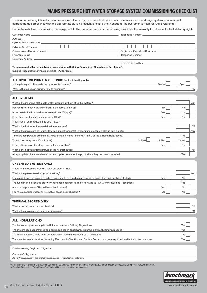
At the time of commissioning, please ensure all relevant sections of the Benchmark Checklist, (Pages 26 and 27) of this document are completed.
FILLING THE UNIT WITH WATER
• Check expansion vessel pre-charge pressure. The vessel is supplied precharged to 3.5 bar to match the control pressure of the pressure reducing valve. The precharge pressure is checked using a car tyre gauge by unscrewing the plastic cap opposite the water connection.
• Check all connections for tightness including the immersion heater(s). An immersion heater key spanner is supplied for this purpose.
• Ensure the drain cock is CLOSED. • Open a hot tap furthest from the PremierPlus SystemFit cylinder.• Open the PremierPlus SystemFit stop cock to fill the unit. When water flows from the tap, allow to run for a few minutes
to thoroughly flush through any residue, dirt or swarf, then close the tap.• Open successive hot taps to purge the system of air.
SYSTEM CHECKS
• Check all water connections for leaks and rectify as necessary.• Turn off PremierPlus SystemFit water supply.• Remove the pressure reducing valve head work to access the strainer mesh, clean and re-fit.• Manually open, for a few seconds, each relief valve in turn, checking that water is discharged and runs freely through
the tundish and out at the discharge point. • Ensure that the valve(s) reseat satisfactorily.
INDIRECT (PRIMARY) CIRCUIT
Fill the indirect (primary) circuit following the boiler manufacturer’s commissioning instructions. To ensure the primary heating system is correctly filled the 2-port motorised valves should be manually opened by moving the lever on the motor housings to the MANUAL OPEN setting. When the primary circuit is full return the levers to the AUTO position. Vent any trapped air. Check the primary system for leaks and rectify as necessary. Flush the primary system in accordance with the boiler manufacturers instructions and add a suitable inhibitor when re-filling.
Switch on the electrical supply to the PremierPlus SystemFit indirect controls and the boiler. Programme the PremierPlus SystemFit controller as detailed in the fitting and user instruction leaflet supplied with the controller. Set the controller for hot water operation only (the +1HR ON Hot Water over-ride button can be used if the time is during a hot water OFF period). Check that the heating 2-port motorised valve is closed and that the hot water 2-port motorised valve opens. The pump should run and the boiler fire (tap symbol appears in controller display). The primary flow to the PremierPlus SystemFit should become hot, if it does not, check for a wiring or piping error.
Allow the PremierPlus SystemFit unit to heat up and check that the hot water thermostat and 2-port motorised valve operate correctly. A storage temperature of approx. 60°C is recommended (see Fig 7, page 16 for adjustment details). If necessary the temperature can be adjusted by inserting a flat bladed screwdriver in the adjustment knob and rotating. The minimum thermostat setting is 10°C. The adjustment range on the spindle represents a temperature range of 10° to 72°C.
Select the heating only function on the controller. NOTE: The room temperature is set at the controller, no adjustment is possible at the room sensor unit. Check that the heating 2-port motorised valve opens and that the hot water 2-port motorised valve is closed. The pump should run and the boiler fire (a flame symbol appears in the controller display). The primary flow to the PremierPlus SystemFit and the radiator circuit should become hot, if it does not check for a wiring or piping error.
If a second CH zone is fitted, adjust the programmable room thermostat so that it is calling for heat. Check that the second CH zone valve opens. The pump should run and the boiler fire. The primary flow to the second CH zone should become hot, if it does not check for a wiring or piping error.
Select the heating and hot water control function on the controller. Check that the heating 2-port motorised valve and the hot water 2-port motorised valve open.
The minimum thermostatic setting is 10 °C. The maximum thermostatic setting is 72 °C.
19
NOTE: it may be necessary to cool the PremierPlus SystemFit down to allow the indirect thermostat to call for heat, it may also be necessary to increase the required room temperature setting if the room temperature has already reached that programmed. The pump should run and the boiler fire (both a tap symbol and a flame symbol should appear in the controller display). The primary flow to the Premier Plus SystemFit and the radiator circuit should become hot. If it does not, check for a wiring or piping error.
When the heating and hot water temperatures are reached, the 2-port motorised valves should close, the pump stops running and the boiler stops firing. NOTE: If a pump over-run boiler is fitted, the pump may continue to run for a short time after the boiler has shut down.
Check that no water is discharged from either the expansion valve or temperature and pressure relief valve during the heating cycle. If the user temperatures or “On” and “Off” times have been adjusted for commissioning purposes, the controller should be reset to the desired settings. The operation of the controller should be demonstrated to the user and the controller installation and user instructions left with them for future reference.
AUTOMATIC SYSTEM BY-PASS
An automatic differential bypass valve is fitted to the PremierPlus SystemFit. This has been factory set to an optimum position for most domestic heating systems. However, in some systems it may require further adjustment. To do this:Turn the adjustment spindle fully clockwise such that the 0.5 marking is level with the top of the valve body. Turn on the system and set the controller to heating only. Balance the system in the normal manner. With the boiler firing and the pump running, slowly turn the adjustment knob anti-clockwise until hot water can be felt on the outlet side of the bypass valve. Turn the adjustment knob clockwise by half a turn.
MAINTENANCE
MAINTENANCE REQUIREMENTS
Unvented hot water systems have a continuing maintenance requirement in order to ensure safe working and optimum performance. It is essential that the relief valve(s) are periodically inspected and manually opened to ensure no blockage has occurred in the valves or discharge pipework. Similarly cleaning of the strainer element and replacement of the air in the expansion vessel will help to prevent possible operational faults.
The maintenance checks described below should be performed by a competent person on a regular basis, e.g. annually to coincide with boiler maintenance.
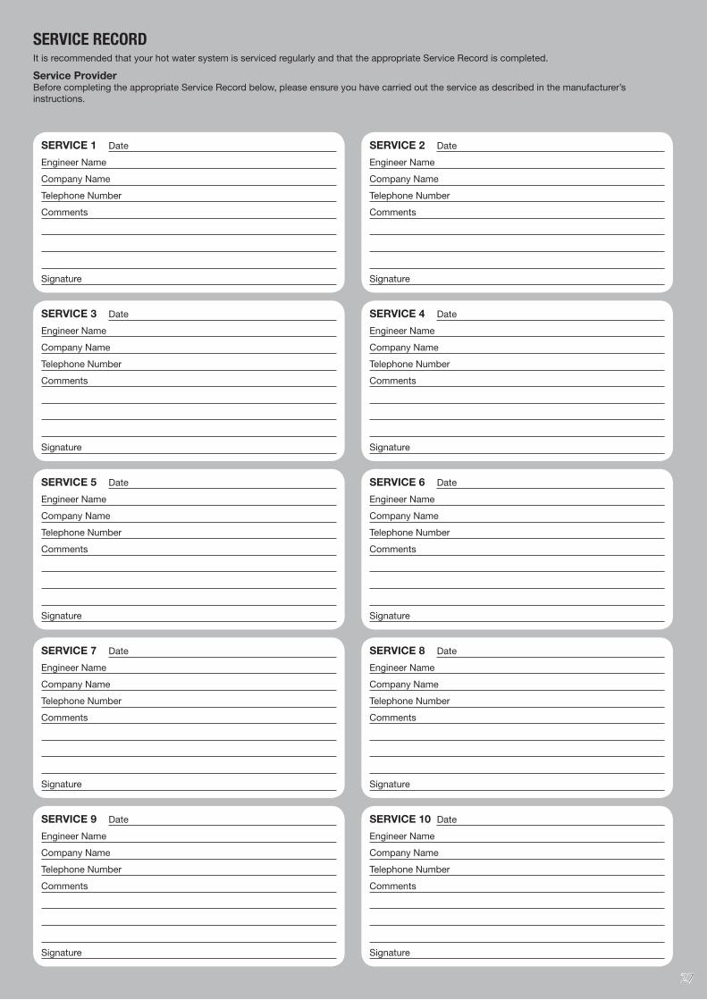
After any maintenance, please complete the relevant service interval record section of the Benchmark Checklist on page 27 of this document.
INSPECTION
The immersion heater boss can be used as an access for inspecting the cylinder internally.
SAFETY VALVE OPERATION
Manually operate the temperature/pressure relief valve for a few seconds. Check water is discharged and that it flows freely through the tundish and discharge pipework. Check valve reseats correctly when released. NOTE: Water discharged may be very hot!
Repeat the above procedure for the expansion relief valve.
STRAINER
Turn off the cold water supply, boiler and immersion heaters. The lowest hot water tap should then be opened to de-pressurise the system. Remove the pressure reducing cartridge to access the strainer mesh. Wash any particulate matter from the strainer under clean water. Re-assemble ensuring the seal is correctly fitted. DO NOT use any other type of sealant.
DESCALING IMMERSION HEATER(S)
Before removing the immersion heater(s), the unit must be drained. Ensure the water, electrical supply and boiler are OFF before draining. Attach a hosepipe to the drain cock having sufficient length to take water to a suitable discharge point below the level of the unit. Open a hot tap close to the unit and open the drain cock to drain the unit.
IMMERSION HEATER REMOVAL
Open the cover(s) to the immersion heater housing(s) and disconnect wiring from immersion heater thermostat(s). Remove thermostat capillary sensors from the pockets on the immersion heater. Unscrew immersion heater backnut(s) and remove immersion heater from the unit. A key spanner is supplied with the cylinder unit for easy removal/tightening of the backnut(s). Over time, the immersion heater gasket may become stuck to the mating surface. To break the seal, insert a round bladed screwdriver into one of the pockets on the immersion heater and gently lever up and down.
Carefully remove any scale from the surface of the element(s). DO NOT use a sharp implement as damage to the element surface could be caused. Ensure sealing surfaces are clean and seals are undamaged, if in doubt fit a new gasket(part number 95 611 822).
Replace immersion heater(s) ensuring the lower (right angled) element hangs vertically downwards towards the base of the unit. It may be helpful to support the immersion heater using a round bladed screwdriver inserted into one of the thermostat pockets whilst the backnut is tightened. Replace thermostat capillaries into pocket. Replace the immersion heater thermostat by carefully plugging the two male spade terminations on the underside of the thermostat head into the corresponding terminations on the element. Rewire, check, close and secure immersion heater housing cover(s).
EXPANSION VESSEL CHARGE PRESSURE
Remove the dust cap on top of the vessel. Check the charge pressure using a tyre pressure gauge. The pressure (with system de-pressurised) should be 0.35MPa (3.5 bar). If it is lower than the required setting it should be re-charged using a tyre pump (Schrader valve type). DO NOT OVER-CHARGE. Re-check the pressure and when correct replace the dust cap.
RE-COMMISSIONING
Check all electrical and plumbing connections are secure. Close the drain cock. With a hot tap open, turn on the cold water supply and allow unit to refill. DO NOT switch on the immersion heater(s) or boiler until the unit is full. When water flows from the hot tap, allow to flow for a short while to purge air and flush through any disturbed particles. Close hot tap and then open successive hot taps in the system to purge any air. When completely full and purged, check system for leaks. The heating source (immersion heater(s) or boiler) can then be switched on.
BENCHMARK LOG BOOK
On completion of any maintenance or service of the PremierPlus SystemFit, the Benchmark “Installation, Commissioning and Service Record Log Book” should be filled in to record the actions taken and the date the work was undertaken.
USER INSTRUCTIONS
WARNINGS
IF WATER ISSUES FROM THE TEMPERATURE/PRESSURE RELIEF VALVE ON THE PREMIERPLUS SYSTEMFIT CYLINDER SHUT DOWN THE BOILER. DO NOT TURN OFF ANY WATER SUPPLY. CONTACT A COMPETENT INSTALLER FOR UNVENTED WATER HEATERS TO CHECK THE SYSTEM.
DO NOT TAMPER WITH ANY OF THE SAFETY VALVES FITTED TO THE PREMIERPLUS SYSTEMFIT. IF A FAULT IS SUSPECTED, CONTACT A COMPETENT INSTALLER.
BENCHMARK
The PremierPlus SystemFit cylinder is covered by the Benchmark Scheme which aims to improve the standards of installation and commissioning of domestic heating and hot water systems in the UK and to encourage regular servicing to optimise safety, efficiency and performance.
Benchmark is managed and promoted by the Heating and Hotwater Industry Council. For more information visit www.centralheating.co.uk.
Please ensure that the installer has fully completed the Benchmark Checklist (page 26 and 27) of this manual and that you have signed it to say that you have received a full and clear explanation of its operation. The installer is legally required to complete a commissioning checklist as a means of complying with the appropriate Building Regulations (England and Wales).
All installations must be notified to Local Area Building Control either directly or through a Competent Persons Scheme. A Building Regulations Compliance Certificate will then be issued to the customer who should, on receipt, write the Notification Number on the Benchmark Checklist.
This product should be serviced regularly to optimise its safety, efficiency and performance. The service engineer should complete the relevant Service Record on the Benchmark Checklist after each service.
20
21
TEMPERATURE CONTROLS IMMERSION HEATER(S)
A combined adjustable thermostat and thermal cut-out is provided for each immersion heater. The thermostat is factory set to give a water storage temperature of approx. 55° to 60°C. Access to the thermostat can be made by opening the immersion heater cover - DISCONNECT THE ELECTRICAL SUPPLY BEFORE OPENING THE COVER(S). Temperature adjustment is made by inserting a flat bladed screwdriver in the slot on the adjustment disc on top of the thermostat and rotating. The adjustment range on the spindle represents a temperature range of 10°C to 72°C. If in any doubt contact a competent electrician.
DO NOT bypass the thermal cut-out(s) in any circumstances.
HEATING BY BOILER
The PremierPlus SystemFit cylinder units are fitted with an indirect thermostat and thermal cut-out. These controls must be wired in series with the 2 port motorised zone valve supplied to interrupt the flow of primary water around the heat exchanger coil when the control temperature has been reached. The controls are located within the lower terminal housing along with the immersion heater thermostat. The thermostat is factory set to give a water storage temperature of approx. 55° to 60°C. Access to the thermostat can be made by opening the terminal housing cover - DISCONNECT THE ELECTRICAL SUPPLY BEFORE OPENING THE COVER. Temperature adjustment is made by inserting a flat bladed screwdriver in the adjustment knob and rotating. The minimum thermostat setting is 10°C. The adjustment range on the spindle gives a temperature range of 10° to 72°C (see Fig 7, page 16 for adjustment details). If in any doubt contact a competent electrician.
An immersion heater is also provided for use, should the indirect heat source be shut down for any purpose. The immersion heater control temperature is set using the immersion heater thermostat.
DO NOT bypass the thermal cut-out(s) in any circumstances.
The space heating control temperature and the operating times for heating and hot water are set using the remotely mounted controller. The optimum temperatures and times will have been set during commissioning. Should the temperatures or timings need to be altered, refer to the installation and user instructions leaflet supplied with the controller for the method of adjustment. If a second CH zone is fitted, this will be controlled by its own programmable room thermostat. Refer to the manufacturers installation and user instructions supplied with the programmable room thermostat for the method of setting and adjustment of heating times and temperatures.
FLOW PERFORMANCE
When initially opening hot outlets a small surge in flow may be noticed as pressures stabilise. This is quite normal with unvented systems. In some areas cloudiness may be noticed in the hot water. This is due to aeration of the water is quite normal and will quickly clear.
OPERATIONAL FAULTS
Operational faults and their possible causes are detailed in the Fault Finding section (page 22) of this book. It is recommended that faults should be checked by a competent installer.
The air volume within the expansion vessel will periodically require recharging to ensure expanded water is accommodated within the unit. A discharge of water INTERMITTENTLY from the expansion valve will indicate the air volume has reduced to a point where it can no longer accommodate the expansion.
FAULT FINDING & SERVICING
IMPORTANT
• After servicing, complete the relevant Service Interval Record section of the Benchmark Checklist located on pages 26 and 27 of this document.
• Servicing should only be carried out by competent persons in the installation and maintenance of unvented water heating systems.
• Any spare parts used MUST be authorised Santon parts.• Disconnect the electrical supply before removing any electrical equipment covers.• NEVER bypass any thermal controls or operate system without the necessary safety valves.• Water contained in the PremierPlus SystemFit cylinder may be very hot, especially following a thermal control failure.
Caution must be taken when drawing water from the unit.
SPARE PARTS
A full range of spare parts are available for the PremierPlus SystemFit cylinder range (see Table 5, page 23). Refer to the technical data label on the unit to identify the model installed and ensure the correct part is ordered. You will need to quote the serial number which is printed on the data label.
FAULT FINDING
The fault finding chart (above) will enable operational faults to be identified and their possible causes rectified. Any work carried out on the PremierPlus SystemFit cylinder unvented water heater and its associated controls MUST be carried out by a competent installer for unvented water heating systems. In case of doubt contact Service Support (see contact details on back page).
WARNINGDO NOT TAMPER WITH ANY OF THE SAFETY VALVES OR CONTROLS SUPPLIED WITH THE PREMIERPLUS SYSTEMFIT CYLINDER AS THIS WILL INVALIDATE ANY GUARANTEE.
22
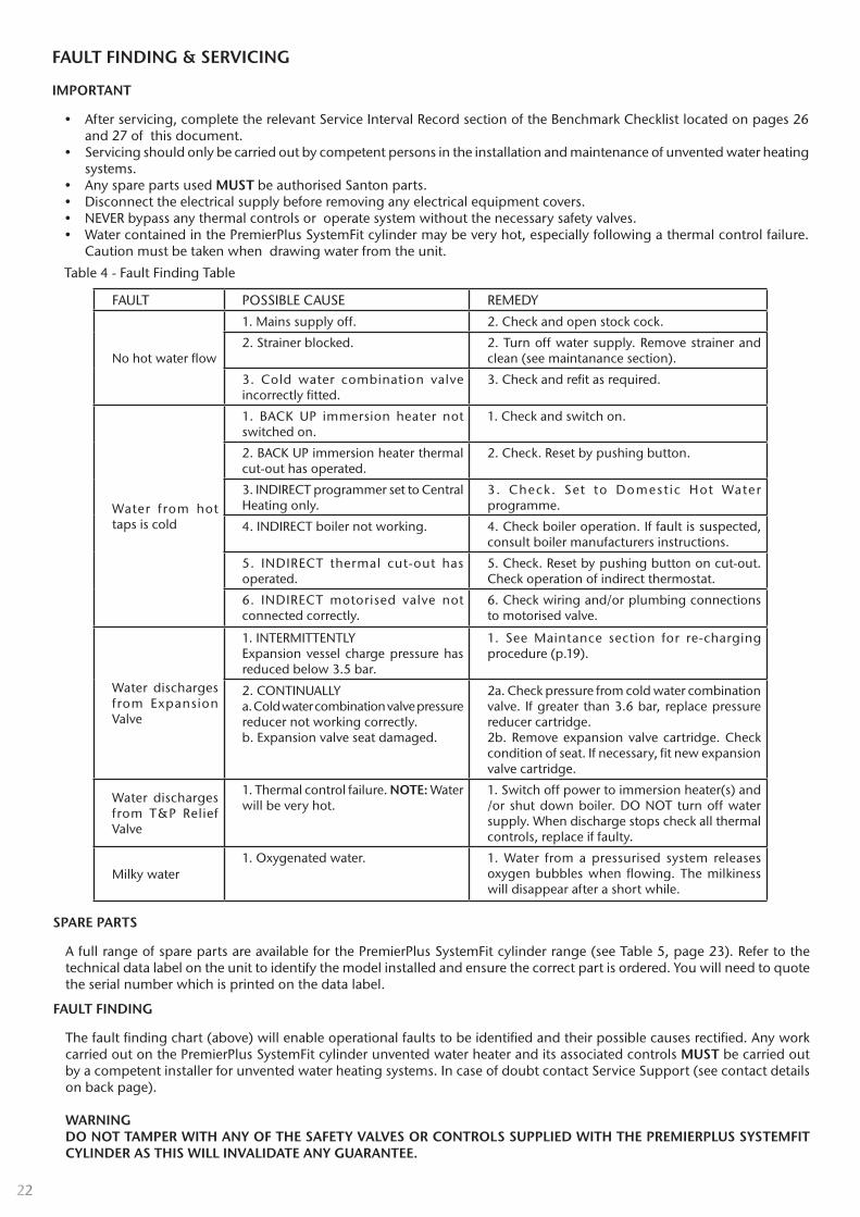
Table 4 - Fault Finding Table
FAULT POSSIBLE CAUSE REMEDY
No hot water flow
1. Mains supply off. 2. Check and open stock cock.
2. Strainer blocked. 2. Turn off water supply. Remove strainer and clean (see maintanance section).
3. Cold water combination valve incorrectly fitted.
3. Check and refit as required.
Water from hot taps is cold
1. BACK UP immersion heater not switched on.
1. Check and switch on.
2. BACK UP immersion heater thermal cut-out has operated.
2. Check. Reset by pushing button.
3. INDIRECT programmer set to Central Heating only.
3. Check . Set to Domest ic Hot Water programme.
4. INDIRECT boiler not working. 4. Check boiler operation. If fault is suspected, consult boiler manufacturers instructions.
5. INDIRECT thermal cut-out has operated.
5. Check. Reset by pushing button on cut-out. Check operation of indirect thermostat.
6. INDIRECT motorised valve not connected correctly.
6. Check wiring and/or plumbing connections to motorised valve.
Water discharges from Expansion Valve
1. INTERMITTENTLYExpansion vessel charge pressure has reduced below 3.5 bar.
1. See Maintance section for re-charging procedure (p.19).
2. CONTINUALLYa. Cold water combination valve pressure reducer not working correctly.b. Expansion valve seat damaged.
2a. Check pressure from cold water combination valve. If greater than 3.6 bar, replace pressure reducer cartridge.2b. Remove expansion valve cartridge. Check condition of seat. If necessary, fit new expansion valve cartridge.
Water discharges from T&P Relief Valve
1. Thermal control failure. NOTE: Water will be very hot.
1. Switch off power to immersion heater(s) and /or shut down boiler. DO NOT turn off water supply. When discharge stops check all thermal controls, replace if faulty.
Milky water1. Oxygenated water. 1. Water from a pressurised system releases
oxygen bubbles when flowing. The milkiness will disappear after a short while.
23
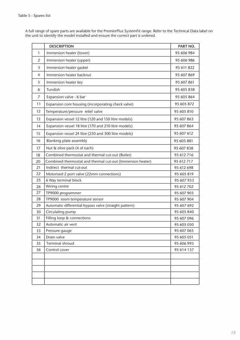
Table 5 - Spares list
DESCRIPTION PART NO.
1 Immersion heater (lower) 95 606 984
2 Immersion heater (upper) 95 606 986
3 Immersion heater gasket 95 611 822
4 Immersion heater backnut 95 607 869
5 Immersion heater key 95 607 861
6 Tundish 95 605 838
7 Expansion valve - 6 bar 95 605 864
11 Expansion core housing (incorporating check valve) 95 605 872
12 Temperature/pressure relief valve 95 605 810
13 Expansion vessel 12 litre (120 and 150 litre models) 95 607 863
14 Expansion vessel 18 litre (170 and 210 litre models) 95 607 864
15 Expansion vessel 24 litre (250 and 300 litre models) 95 607 612
16 Blanking plate assembly 95 605 881
17 Nut & olive pack (4 of each) 95 607 838
18 Combined thermostat and thermal cut-out (Boiler) 95 612 716
20 Combined thermostat and thermal cut-out (Immersion heater) 95 612 717
21 Indirect thermal cut-out 95 612 698
22 Motorised 2 port valve (22mm connections) 95 605 819
95 607 93325 6 Way terminal block
26 Wiring centre 95 612 702
27 TP9000 programmer 95 607 903
28 TP9000 room temperature sensor 95 607 904
29 Automatic differential bypass valve (straight pattern) 95 607 692
30 Circulating pump 95 605 840
31 Filling loop & connections 95 607 096
32 Automatic air vent 95 605 050
33 Pressure gauge 95 607 065
34 Drain valve 95 605 051
35 Terminal shroud 95 606 993
36 Control cover 95 614 137
A full range of spare parts are available for the PremierPlus SystemFit range. Refer to the Technical Data label onthe unit to identify the model installed and ensure the correct part is ordered.
24
2018 1
2534 3536
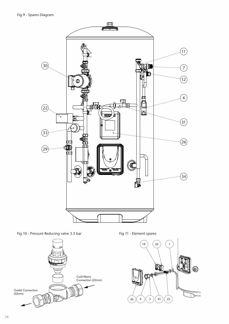
Fig 9 - Spares Diagram
Fig 10 - Pressure Reducing valve 3.5 bar Fig 11 - Element spares
11
7
12
6
31
34
26
29
33
22
30
Cold MainsConnection (22mm)
Outlet Connection(22mm)
GUARANTEE
WARNING: Should the factory fitted temperature and pressure relief valve be tampered with or removed your guarantee will be invalidated. Neither the distributor nor manufacturer shall be responsible for any consequential damage howsoever caused.
Guarantee Terms
Santon guarantees the PremierPlus SystemFit against faulty manufacture or materials for a period of 2 years from the date of purchase including parts and labour. This 2 year guarantee is extended to 5 years for the expansion vessel and cold water control valve and to 30 years for the stainless steel inner vessel.
These guarantees are valid provided that:
The PremierPlus SystemFit has been installed by a competent installer and as per the instructions contained in the installation manual and all relevant Codes of Practice and Regulations in force at the time of installation.
Any disinfection has been carried out in accordance with BS 6700.
The PremierPlus SystemFit has not been modified in any way other than by heateam approved engineers.
The PremierPlus SystemFit has only been used for the storage of wholesome water (max. 250mg/l chloride).
The PremierPlus SystemFit has not been subjected to frost, nor has it been tampered with or been subjected to misuse or neglect.
No factory fitted parts have been removed for unauthorised repair or replacement.
The BenchmarkTM Commissioning Checklist Service Record included in this product guide has been completed.
Regular maintenance has been carried out by a competent person in accordance with the requirements set out in the maintenance section of the installation manual and any replacement parts used should be authorised Santon spare parts. Annual services are available from heateam, the service division of Santon. Please contact heateam on Tel: 0844 871 1530 for further details.
Within 60 days of purchase the owner completes and returns the certificate supplied to register the product. Evidence of purchase and date of supply must be submitted upon making a claim.
This guarantee is not valid for installations outside the United Kingdom.
For installations outside of the United Kingdom, please contact either the Santon Export Department on Tel: +44 1603 420271 or Baxi International on Tel: +44 1926 478323 for further details of the guarantee terms and conditions applicable.
This guarantee does not affect your statutory rights.
The unit is not guaranteed against damage due to frost.
ENVIROMENTAL
Products are manufactured from many recyclable materials. At the end of their useful life they should be disposed of at a Local Authority Recycling Centre in order to realise the full environmental benefits.
Insulation is by means of an approved CFC/HCFC free polyurethane foam with an ozone depletion factor of zero.
25
26
27
SPARES STOCKISTS
Advanced Water Company Ltd Unit D5 Enterprise Way, Vale Park, Evesham, Worcs, WR11 1GS Tel: 01386 760066 Fax: 01386 760077
Electric Water Heating Co.2 Horsecroft PlacePinnaclesHarlowEssexCM19 5BTTel: 0845 0553811E-Mail: [email protected]
SPDSpecial Product DivisionUnits 9 & 10Hexagon Business CentreSpringfield RoadHayesMiddlesexUB4 0TYTel: 0208 5730574
Parts CenterTel: 0845 2709800www.partscenter.co.uk
Newey & EyreSpecialist Products DivisionUnit 3/4/5 Wassage Way,Hampton Lovett Industrial Estate,Droitwich, Worcestershire, WR9 0NXTel: 01905 791500Fax: 01905 791501
UK Spares LtdUnit 1155Aztec WestAlmondsburyBristolBS32 4TFTel: 01454 620500
Alternatively contact your local supplying merchant or wholesale branch.
The policy of Santon is one of continuous product development and, as such, we reserve the right to change specifications and guarantee terms and conditions without notice.
36006155_issue_06
Customer ServiceService: 0844 871 1530Service fax: 0844 871 1528Email: [email protected]
SantonHurricane WayNorwichNorfolkNR6 6EA
28