Embed Size (px)
Citation preview
Mission 3D Inverter Series
Service Manual 2014
MBSEU-A-1412
CONTENTS 1. Precaution .................................................................................................................................................... 3
1.1 Safety Precaution .......................................................................................................................... 3
1.2 Warning ......................................................................................................................................... 3
2. Function ........................................................................................................................................................ 6
3. Dimension .................................................................................................................................................... 7
3.1 Indoor Unit ..................................................................................................................................... 7
3.2 Outdoor Unit ................................................................................................................................ 10
4. Refrigerant Cycle Diagram ....................................................................................................................... 13
5 Installation Details ...................................................................................................................................... 14
5.1 Wrench torque sheet for installation ........................................................................................... 14
5.2 Connecting the cables ................................................................................................................ 14
5.3 Pipe length and the elevation ..................................................................................................... 15
5.4 Installation for the first time ......................................................................................................... 16
5.5 Adding the refrigerant after running the system for many years ................................................ 17
5.6 Re-installation while the indoor unit need to be repaired ........................................................... 18
5.7 Re-installation while the outdoor unit need to be repaired ......................................................... 19
6. Operation Characteristics ......................................................................................................................... 21
7. Electronic function .................................................................................................................................... 22
7.1 Abbreviation ................................................................................................................................ 22
7.2 Display function ........................................................................................................................... 22
7.3 Main Protection ........................................................................................................................... 23
7.4 Operation Modes and Functions ................................................................................................. 24
8. Troubleshooting ......................................................................................................................................... 28
8.1 Indoor Unit Error Display ............................................................................................................. 29
8.2 Trouble shooting.......................................................................................................................... 30
1. Precaution
1.1 Safety Precaution
To prevent injury to the user or other
people and property damage, the following
instructions must be followed.
Incorrect operation due to ignoring
instruction will cause harm or damage.
Before service the unit, be sure to
read this service manual at first.
1.2 Warning
Installation
Do not use a defective or underrated
circuit breaker. Use this appliance on a
dedicated circuit.
There is risk of fire or electric shock.
For electrical work, contact the dealer,
seller, a qualified electrician, or an
authorized service center.
Do not disassemble or repair the product,
there is risk of fire or electric shock.
Always ground the product.
There is risk of fire or electric shock.
Install the panel and the cover of
control box securely.
There is risk of fire of electric shock.
Always install a dedicated circuit and
breaker.
Improper wiring or installation may cause fore
or electric shock.
Use the correctly rated breaker of
fuse.
There is risk of fire or electric shock.
Do not modify or extend the power
cable.
There is risk of fire or electric shock.
Do not install, remove, or reinstall the
unit by yourself (customer).
There is risk of fire, electric shock, explosion,
or injury.
Be caution when unpacking and
installing the product.
Sharp edges could cause injury, be especially
careful of the case edges and the fins on the
condenser and evaporator.
For installation, always contact the
dealer or an authorized service center.
Do not install the product on a
defective installation stand.
Be sure the installation area does not
deteriorate with age.
If the base collapses, the air conditioner could
fall with it, causing property damage, product
failure, and personal injury.
Do not let the air conditioner run for a
long time when the humidity is very high
and a door or a window is left open.
Take care to ensure that power cable
could not be pulled out or damaged during
operation.
There is risk of fire or electric shock.
Do not place anything on the power
cable.
There is risk of fire or electric shock.
Do not plug or unplug the power
supply plug during operation.
There is risk of fire or electric shock.
Do not touch (operation) the product
with wet hands.
Do not place a heater or other
appliance near the power cable.
There is risk of fire and electric shock.
Do not allow water to run into
electrical parts.
It may cause fire, failure of the product, or
electric shock.
Do not store or use flammable gas or
combustible near the product.
There is risk of fire or failure of product.
Do not use the product in a tightly
closed space for a long time.
Oxygen deficiency could occur.
When flammable gas leaks, turn off
the gas and open a window for ventilation
before turn the product on.
If strange sounds or smoke comes
from product, turn the breaker off or
disconnect the power supply cable.
There is risk of electric shock or fire.
Stop operation and close the window
in storm or hurricane. If possible, remove
the product from the window before the
hurricane arrives.
There is risk of property damage, failure of
product, or electric shock.
Do not open the inlet grill of the
product during operation. (Do not touch the
electrostatic filter, if the unit is so equipped.)
There is risk of physical injury, electric shock,
or product failure.
When the product is soaked, contact
an authorized service center.
There is risk of fire or electric shock.
Be caution that water could not enter
the product.
There is risk of fire, electric shock, or product
damage.
Ventilate the product from time to
time when operating it together with a stove
etc.
There is risk of fire or electric shock.
Turn the main power off when
cleaning or maintaining the product.
There is risk of electric shock.
When the product is not be used for a
long time, disconnect the power supply plug
or turn off the breaker.
There is risk of product damage or failure, or
unintended operation.
Take care to ensure that nobody
could step on or fall onto the outdoor unit.
This could result in personal injury and
product damage.
CAUTION
Always check for gas (refrigerant)
leakage after installation or repair of
product.
Low refrigerant levels may cause failure of
product.
Install the drain hose to ensure that
water is drained away properly.
A bad connection may cause water leakage.
Keep level even when installing the
product.
It can avoid vibration of water leakage.
Do not install the product where the
noise or hot air from the outdoor unit could
damage the neighborhoods.
It may cause a problem for your neighbors.
Use two or more people to lift and
transport the product.
Do not install the product where it will
be exposed to sea wind (salt spray) directly.
It may cause corrosion on the product.
Corrosion, particularly on the condenser and
evaporator fins, could cause product
malfunction or inefficient operation.
Operational
Do not expose the skin directly to
cool air for long time. (Do not sit in the
draft).
Do not use the product for special
purposes, such as preserving foods, works
of art etc. It is a consumer air conditioner,
not a precision refrigerant system.
There is risk of damage or loss of property.
Do not block the inlet or outlet of air
flow.
Use a soft cloth to clean. Do not use
harsh detergents, solvents, etc.
There is risk of fire, electric shock, or damage
to the plastic parts of the product.
Do not touch the metal parts of the
product when removing the air filter. They
are very sharp.
Do not step on or put anything on the
product. (outdoor units)
Always insert the filter securely.
Clean the filter every two weeks or more
often if necessary.
A dirty filter reduces the efficiency of the air
conditioner and could cause product
malfunction or damage.
Do not insert hands or other objects
through air inlet or outlet while the product
is operated.
Do not drink the water drained from
the product.
Use a firm stool or ladder when
cleaning or maintaining the product.
Be careful and avoid personal injury.
Replace the all batteries in the remote
control with new ones of the same type. Do
not mix old and new batteries or different
types of batteries.
There is risk of fire or explosion.
Do not recharge or disassemble the
batteries. Do not dispose of batteries in a
fire.
They may burn of explode.
If the liquid from the batteries gets
onto your skin or clothes, wash it well with
clean water. Do not use the remote of the
batteries have leaked.
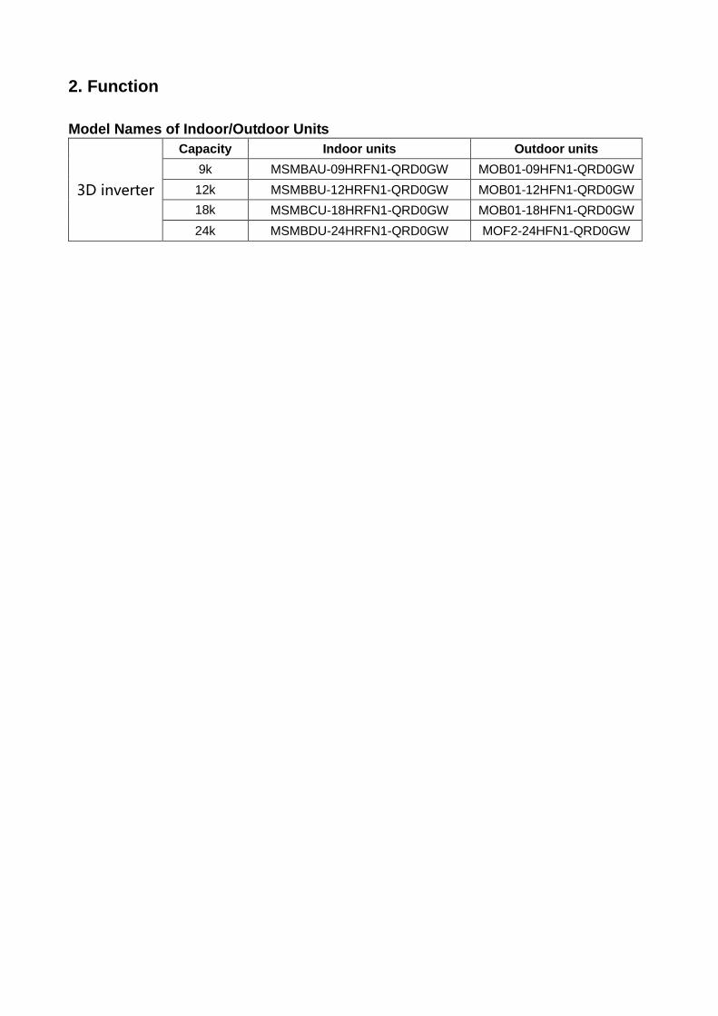
2. Function
Model Names of Indoor/Outdoor Units
3D inverter
Capacity Indoor units Outdoor units
9k MSMBAU-09HRFN1-QRD0GW MOB01-09HFN1-QRD0GW
12k MSMBBU-12HRFN1-QRD0GW MOB01-12HFN1-QRD0GW
18k
MSMBCU-18HRFN1-QRD0GW MOB01-18HFN1-QRD0GW
24k MSMBDU-24HRFN1-QRD0GW MOF2-24HFN1-QRD0GW
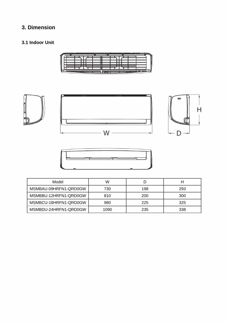
3. Dimension
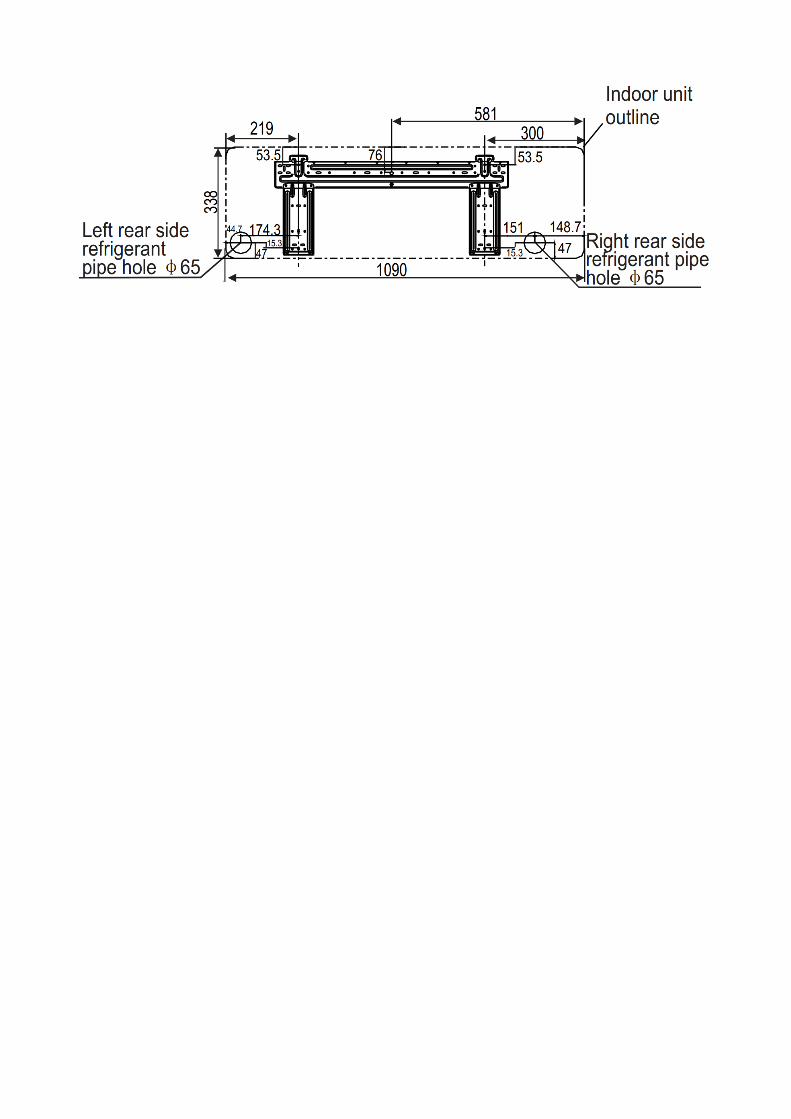
3.1 Indoor Unit
Model W D H
MSMBAU-09HRFN1-QRD0GW 730 198 293
MSMBBU-12HRFN1-QRD0GW 810 200 300
MSMBCU-18HRFN1-QRD0GW 980 225 325
MSMBDU-24HRFN1-QRD0GW 1090 235 338
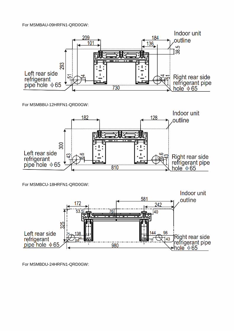
For MSMBAU-09HRFN1-QRD0GW:
For MSMBBU-12HRFN1-QRD0GW:
For MSMBCU-18HRFN1-QRD0GW:
For MSMBDU-24HRFN1-QRD0GW:
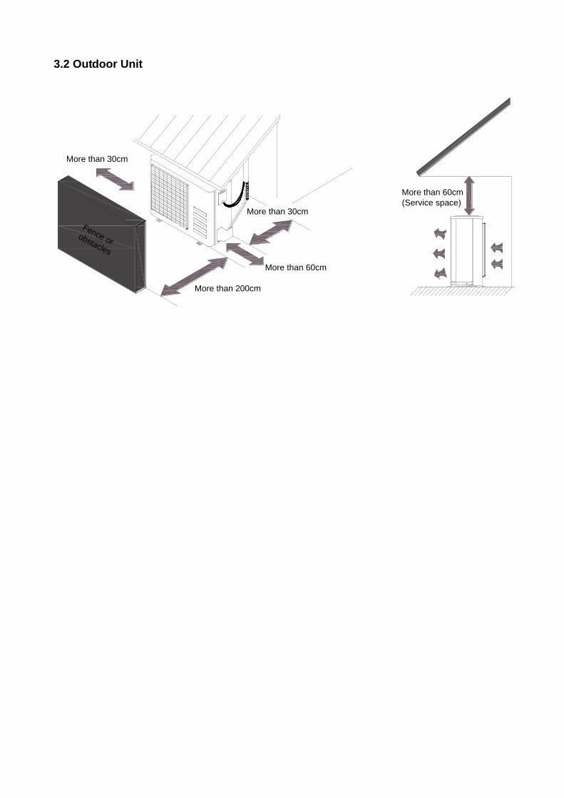
3.2 Outdoor Unit
More than 30cm
More than 60cm
More than 200cm
More than 30cm
More than 60cm
(Service space)
Fence orobstacles
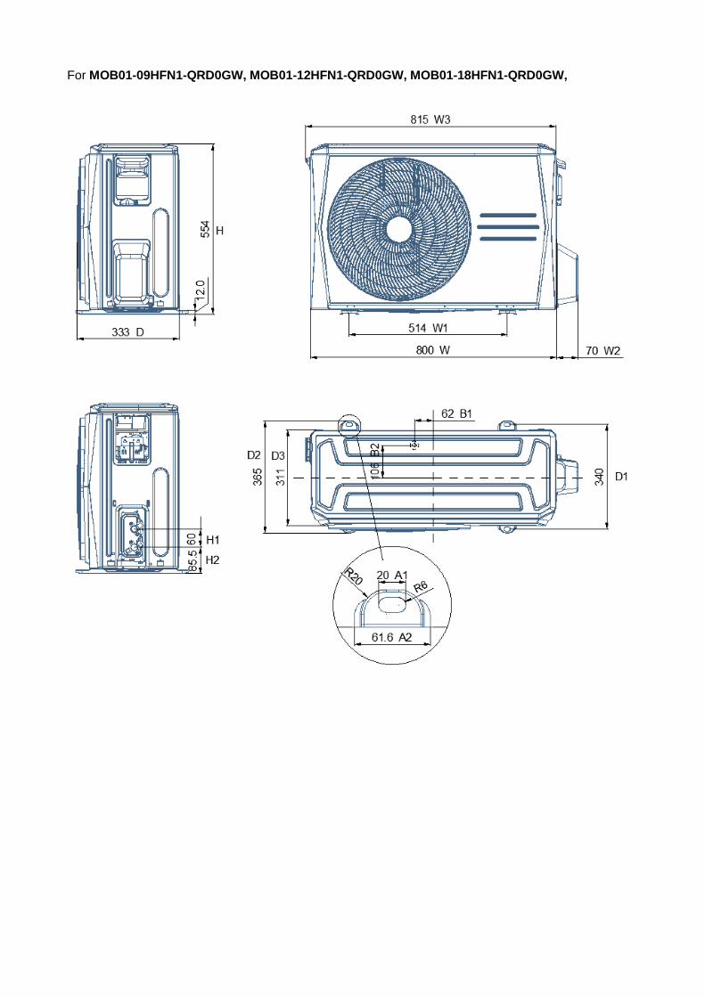
For MOB01-09HFN1-QRD0GW, MOB01-12HFN1-QRD0GW, MOB01-18HFN1-QRD0GW,
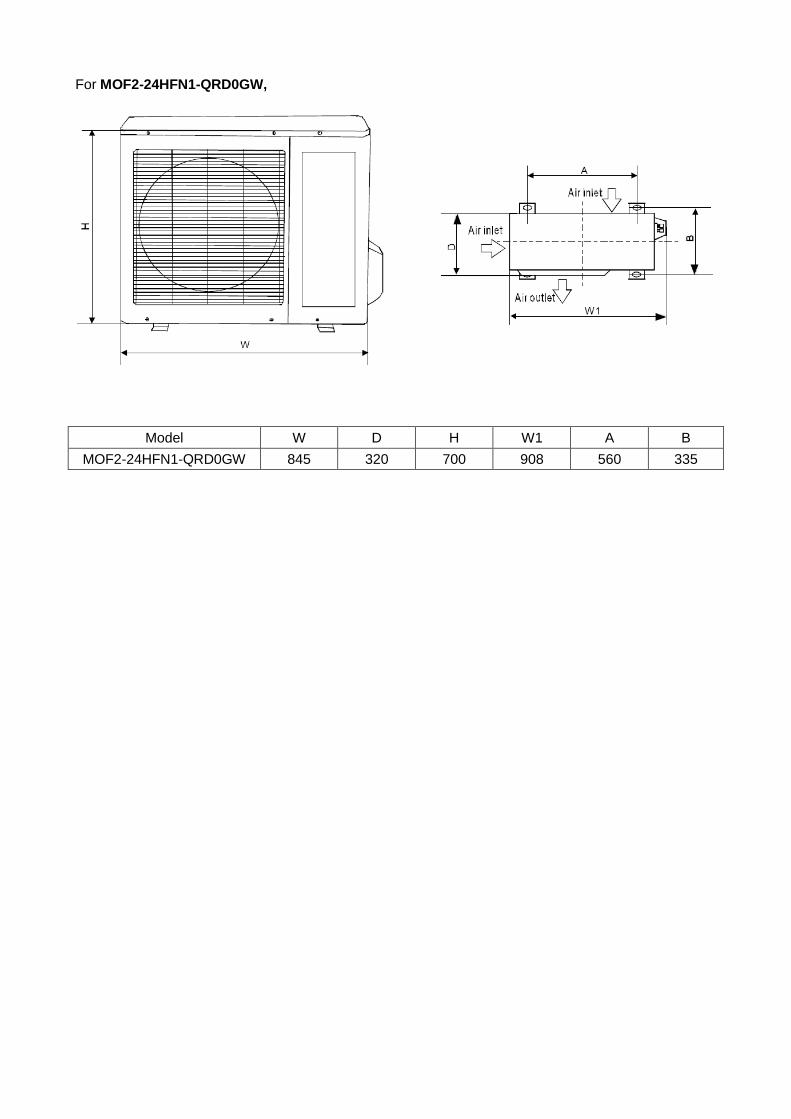
For MOF2-24HFN1-QRD0GW,
Model W D H W1 A B
MOF2-24HFN1-QRD0GW 845 320 700 908 560 335
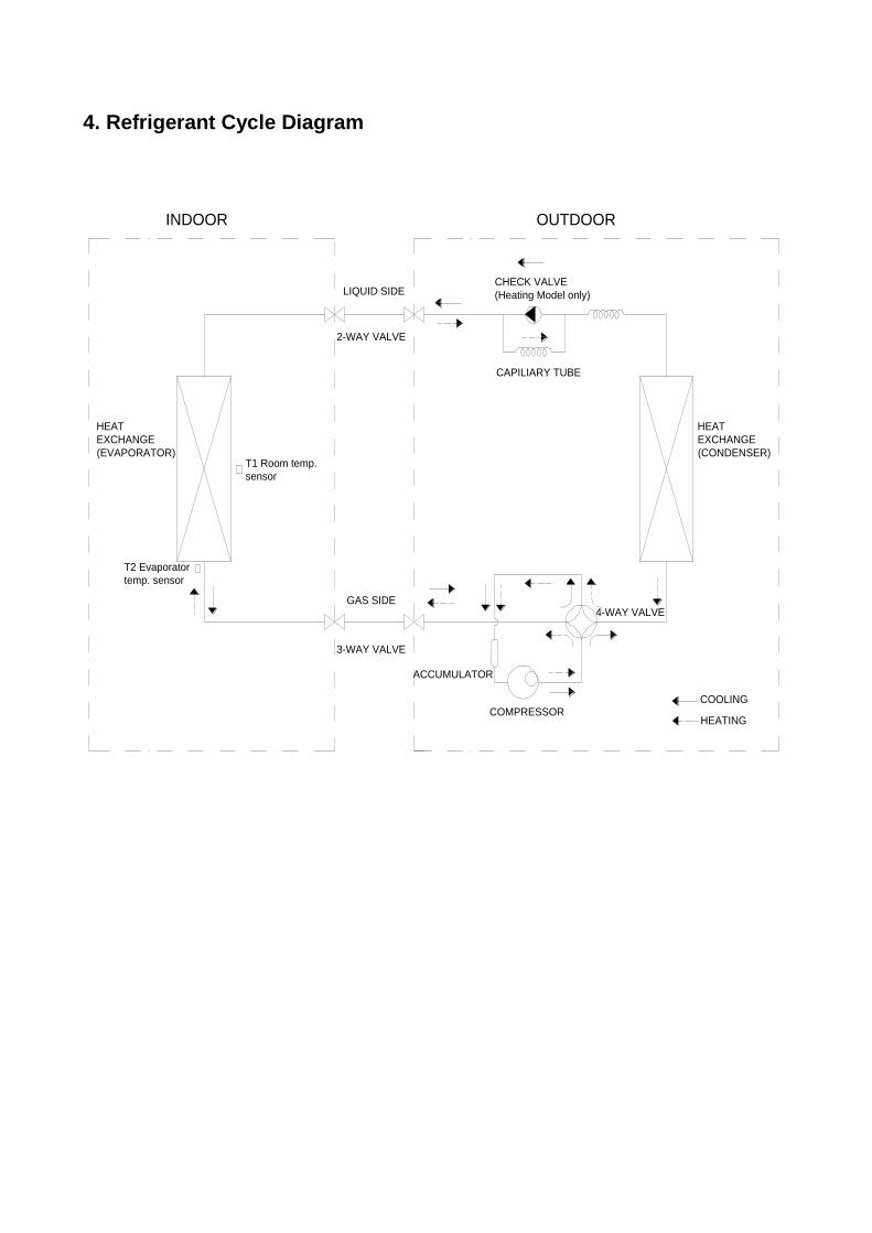
4. Refrigerant Cycle Diagram
LIQUID SIDE
GAS SIDE
HEAT
EXCHANGE
(EVAPORATOR)
HEAT
EXCHANGE
(CONDENSER)
COMPRESSOR
2-WAY VALVE
3-WAY VALVE
4-WAY VALVE
COOLING
HEATING
T2 Evaporator
temp. sensor
T1 Room temp.
sensor
ACCUMULATOR
INDOOR OUTDOOR
CHECK VALVE
(Heating Model only)
CAPILIARY TUBE
5 Installation Details
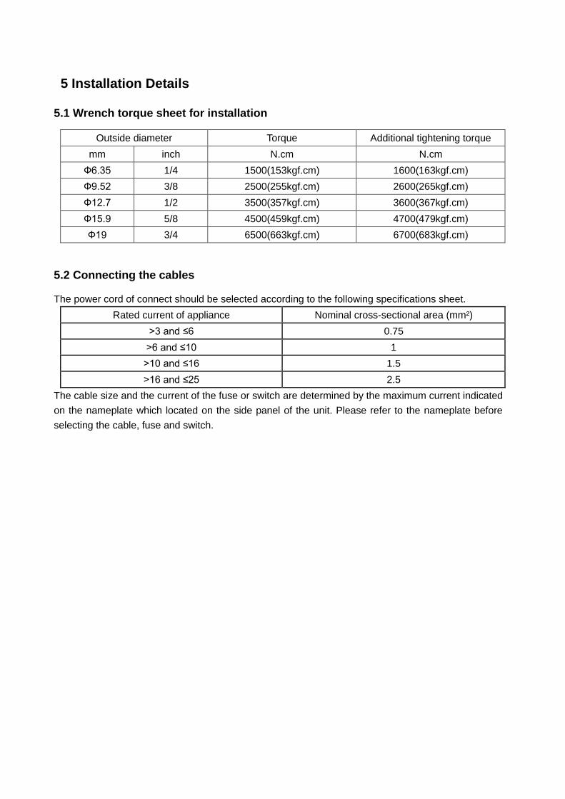
5.1 Wrench torque sheet for installation
Outside diameter Torque Additional tightening torque
mm inch N.cm N.cm
Ф6.35 1/4 1500(153kgf.cm) 1600(163kgf.cm)
Ф9.52 3/8 2500(255kgf.cm) 2600(265kgf.cm)
Ф12.7 1/2 3500(357kgf.cm) 3600(367kgf.cm)
Ф15.9 5/8 4500(459kgf.cm) 4700(479kgf.cm)
Ф19 3/4 6500(663kgf.cm) 6700(683kgf.cm)
5.2 Connecting the cables
The power cord of connect should be selected according to the following specifications sheet.
Rated current of appliance Nominal cross-sectional area (mm²)
>3 and ≤6 0.75
>6 and ≤10 1
>10 and ≤16 1.5
>16 and ≤25 2.5
The cable size and the current of the fuse or switch are determined by the maximum current indicated
on the nameplate which located on the side panel of the unit. Please refer to the nameplate before
selecting the cable, fuse and switch.
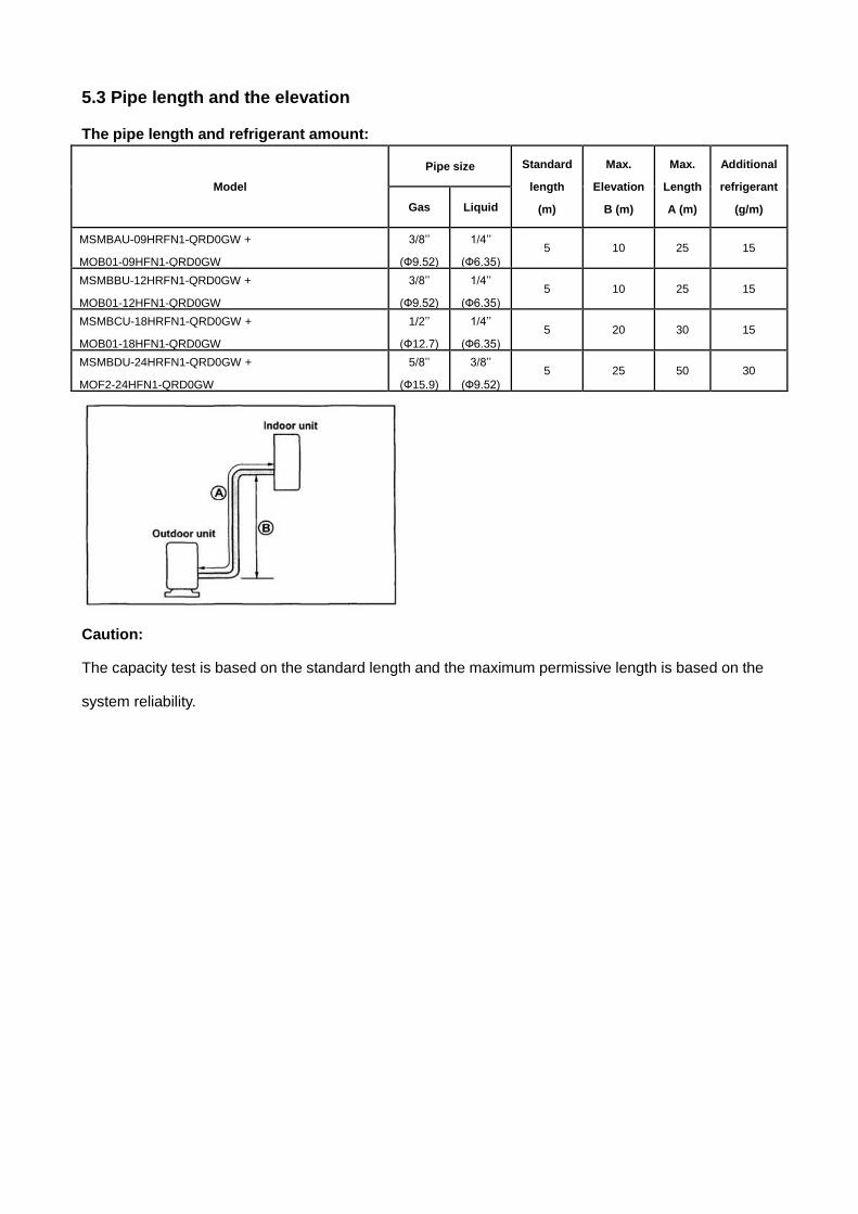
5.3 Pipe length and the elevation
The pipe length and refrigerant amount:
Model
Pipe size Standard
length
(m)
Max.
Elevation
B (m)
Max.
Length
A (m)
Additional
refrigerant
(g/m) Gas Liquid
MSMBAU-09HRFN1-QRD0GW +
MOB01-09HFN1-QRD0GW
3/8’’
(Ф9.52)
1/4’’
(Ф6.35)
5 10 25 15
MSMBBU-12HRFN1-QRD0GW +
MOB01-12HFN1-QRD0GW
3/8’’
(Ф9.52)
1/4’’
(Ф6.35)
5 10 25 15
MSMBCU-18HRFN1-QRD0GW +
MOB01-18HFN1-QRD0GW
1/2’’
(Ф12.7)
1/4’’
(Ф6.35)
5 20 30 15
MSMBDU-24HRFN1-QRD0GW +
MOF2-24HFN1-QRD0GW
5/8’’
(Ф15.9)
3/8’’
(Ф9.52)
5 25 50 30
Caution:
The capacity test is based on the standard length and the maximum permissive length is based on the
system reliability.
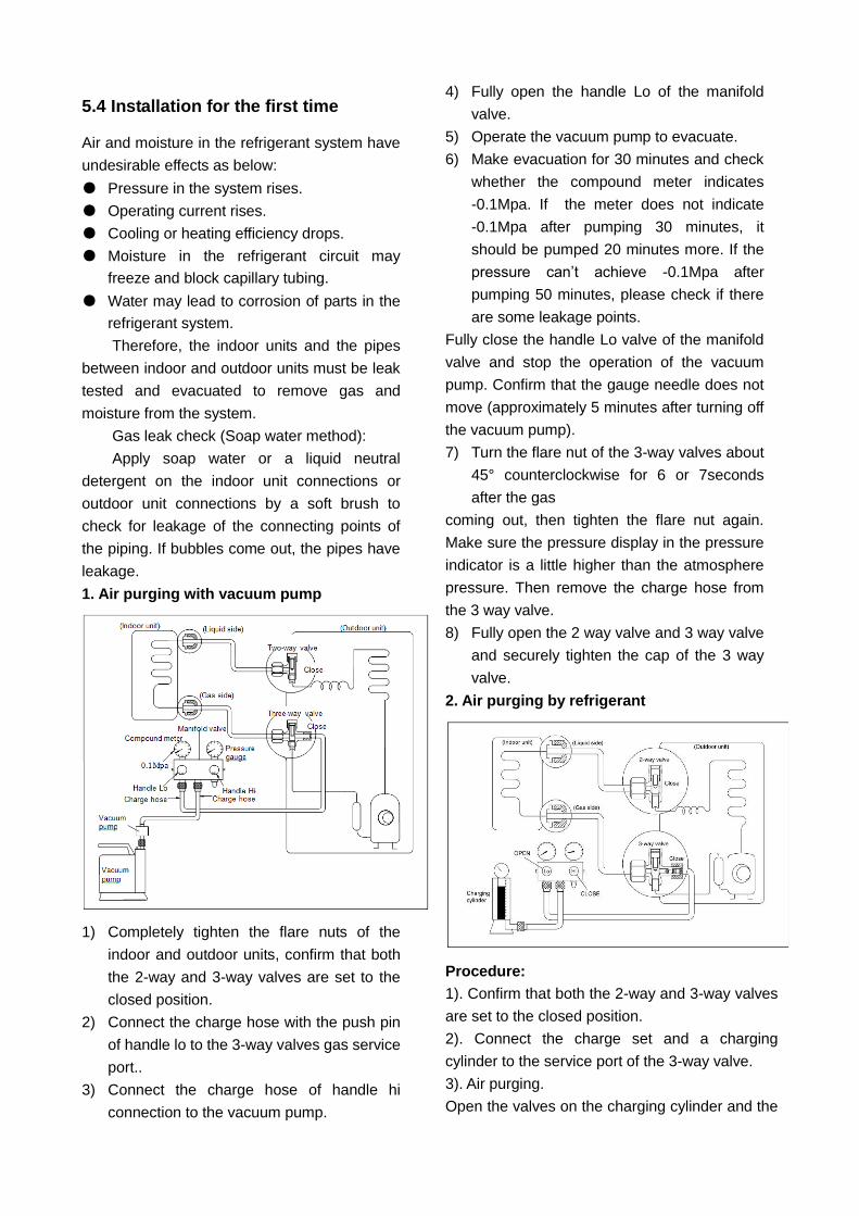
5.4 Installation for the first time
Air and moisture in the refrigerant system have
undesirable effects as below:
● Pressure in the system rises.
● Operating current rises.
● Cooling or heating efficiency drops.
● Moisture in the refrigerant circuit may
freeze and block capillary tubing.
● Water may lead to corrosion of parts in the
refrigerant system.
Therefore, the indoor units and the pipes
between indoor and outdoor units must be leak
tested and evacuated to remove gas and
moisture from the system.
Gas leak check (Soap water method):
Apply soap water or a liquid neutral
detergent on the indoor unit connections or
outdoor unit connections by a soft brush to
check for leakage of the connecting points of
the piping. If bubbles come out, the pipes have
leakage.
1. Air purging with vacuum pump
1) Completely tighten the flare nuts of the
indoor and outdoor units, confirm that both
the 2-way and 3-way valves are set to the
closed position.
2) Connect the charge hose with the push pin
of handle lo to the 3-way valves gas service
port..
3) Connect the charge hose of handle hi
connection to the vacuum pump.
4) Fully open the handle Lo of the manifold
valve.
5) Operate the vacuum pump to evacuate.
6) Make evacuation for 30 minutes and check
whether the compound meter indicates
-0.1Mpa. If the meter does not indicate
-0.1Mpa after pumping 30 minutes, it
should be pumped 20 minutes more. If the
pressure can’t achieve -0.1Mpa after
pumping 50 minutes, please check if there
are some leakage points.
Fully close the handle Lo valve of the manifold
valve and stop the operation of the vacuum
pump. Confirm that the gauge needle does not
move (approximately 5 minutes after turning off
the vacuum pump).
7) Turn the flare nut of the 3-way valves about
45° counterclockwise for 6 or 7seconds
after the gas
coming out, then tighten the flare nut again.
Make sure the pressure display in the pressure
indicator is a little higher than the atmosphere
pressure. Then remove the charge hose from
the 3 way valve.
8) Fully open the 2 way valve and 3 way valve
and securely tighten the cap of the 3 way
valve.
2. Air purging by refrigerant
Procedure:
1). Confirm that both the 2-way and 3-way valves
are set to the closed position.
2). Connect the charge set and a charging
cylinder to the service port of the 3-way valve.
3). Air purging.
Open the valves on the charging cylinder and the
charge set. Purge the air by loosening the flare
nut on the 2-way valve approximately 45’ for 3
seconds then closing it for 1 minute; repeat 3
times.
After purging the air, use a torque wrench to
tighten the flare nut on the 2-way valve.
4). Check the gas leakage.
Check the flare connections for gas leakage.
5). Discharge the refrigerant.
Close the valve on the charging cylinder and
discharge the refrigerant by loosening the flare
nut on the 2-way valve approximately 45’ until the
gauge indicates 0.3 to 0.5 Mpa.
6). Disconnect the charge set and the charging
cylinder, and set the 2-way and 3-way valves to
the open position.
Be sure to use a hexagonal wrench to operate the
valve stems.
7). Mount the valve stems nuts and the service
port cap.
Be sure to use a torque wrench to tighten the
service port cap to a torque 18N·m.
Be sure to check the gas leakage.
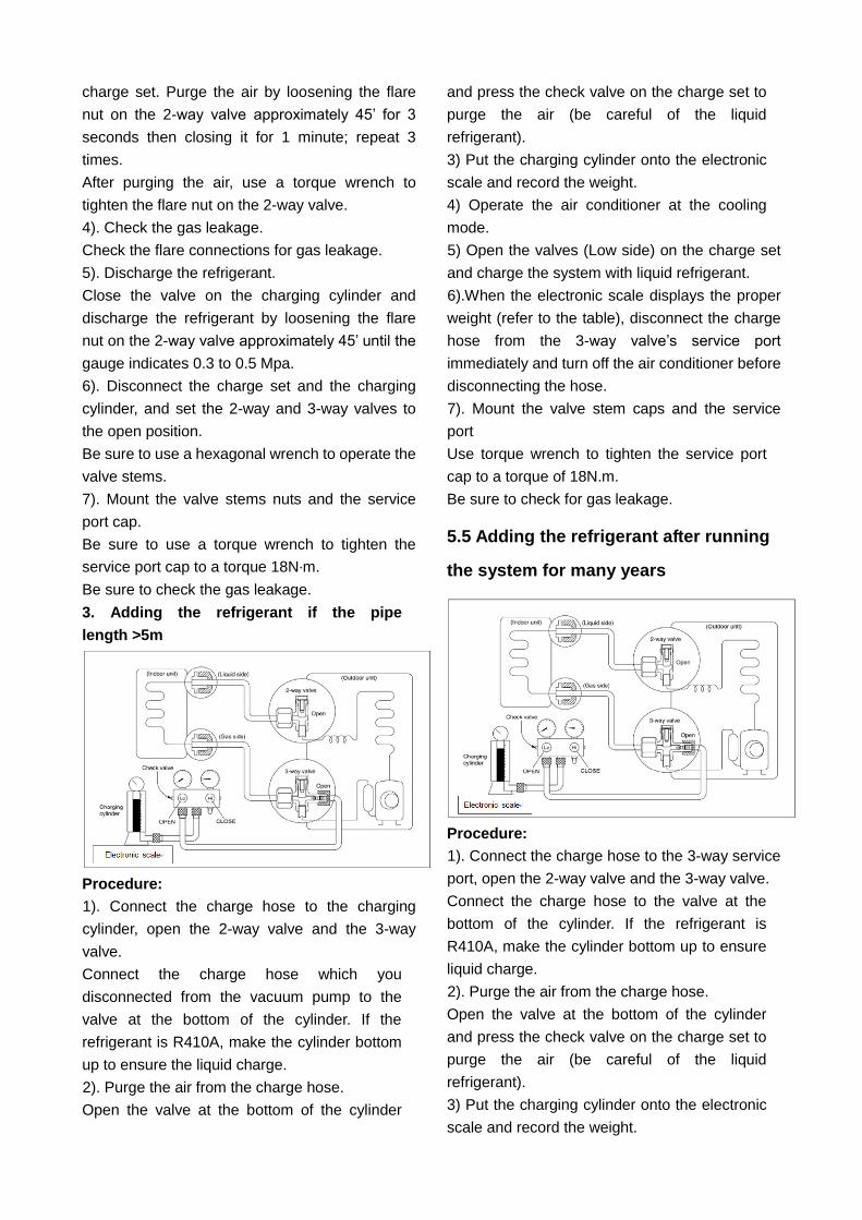
3. Adding the refrigerant if the pipe
length >5m
Procedure:
1). Connect the charge hose to the charging
cylinder, open the 2-way valve and the 3-way
valve.
Connect the charge hose which you
disconnected from the vacuum pump to the
valve at the bottom of the cylinder. If the
refrigerant is R410A, make the cylinder bottom
up to ensure the liquid charge.
2). Purge the air from the charge hose.
Open the valve at the bottom of the cylinder
and press the check valve on the charge set to
purge the air (be careful of the liquid
refrigerant).
3) Put the charging cylinder onto the electronic
scale and record the weight.
4) Operate the air conditioner at the cooling
mode.
5) Open the valves (Low side) on the charge set
and charge the system with liquid refrigerant.
6).When the electronic scale displays the proper
weight (refer to the table), disconnect the charge
hose from the 3-way valve’s service port
immediately and turn off the air conditioner before
disconnecting the hose.
7). Mount the valve stem caps and the service
port
Use torque wrench to tighten the service port
cap to a torque of 18N.m.
Be sure to check for gas leakage.
5.5 Adding the refrigerant after running
the system for many years
Procedure:
1). Connect the charge hose to the 3-way service
port, open the 2-way valve and the 3-way valve.
Connect the charge hose to the valve at the
bottom of the cylinder. If the refrigerant is
R410A, make the cylinder bottom up to ensure
liquid charge.
2). Purge the air from the charge hose.
Open the valve at the bottom of the cylinder
and press the check valve on the charge set to
purge the air (be careful of the liquid
refrigerant).
3) Put the charging cylinder onto the electronic
scale and record the weight.
4) Operate the air conditioner at the cooling
mode.
5) Open the valves (Low side) on the charge set
and charge the system with liquid refrigerant.
6).When the electronic scale displays the proper
weight (refer to the gauge and the pressure of the
low side), disconnect the charge hose from the
3-way valve’s service port immediately and turn
off the air conditioner before disconnecting the
hose.
7). Mount the valve stem caps and the service
port
Use torque wrench to tighten the service port
cap to a torque of 18N.m.
Be sure to check for gas leakage.
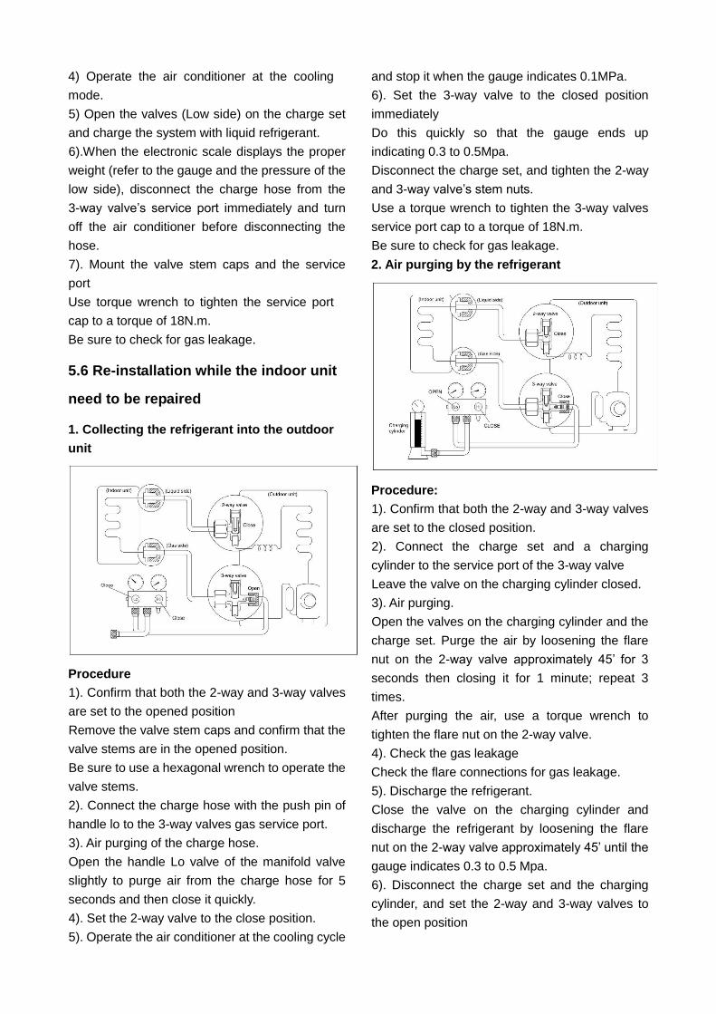
5.6 Re-installation while the indoor unit
need to be repaired
1. Collecting the refrigerant into the outdoor
unit
Procedure
1). Confirm that both the 2-way and 3-way valves
are set to the opened position
Remove the valve stem caps and confirm that the
valve stems are in the opened position.
Be sure to use a hexagonal wrench to operate the
valve stems.
2). Connect the charge hose with the push pin of
handle lo to the 3-way valves gas service port.
3). Air purging of the charge hose.
Open the handle Lo valve of the manifold valve
slightly to purge air from the charge hose for 5
seconds and then close it quickly.
4). Set the 2-way valve to the close position.
5). Operate the air conditioner at the cooling cycle
and stop it when the gauge indicates 0.1MPa.
6). Set the 3-way valve to the closed position
immediately
Do this quickly so that the gauge ends up
indicating 0.3 to 0.5Mpa.
Disconnect the charge set, and tighten the 2-way
and 3-way valve’s stem nuts.
Use a torque wrench to tighten the 3-way valves
service port cap to a torque of 18N.m.
Be sure to check for gas leakage.
2. Air purging by the refrigerant
Procedure:
1). Confirm that both the 2-way and 3-way valves
are set to the closed position.
2). Connect the charge set and a charging
cylinder to the service port of the 3-way valve
Leave the valve on the charging cylinder closed.
3). Air purging.
Open the valves on the charging cylinder and the
charge set. Purge the air by loosening the flare
nut on the 2-way valve approximately 45’ for 3
seconds then closing it for 1 minute; repeat 3
times.
After purging the air, use a torque wrench to
tighten the flare nut on the 2-way valve.
4). Check the gas leakage
Check the flare connections for gas leakage.
5). Discharge the refrigerant.
Close the valve on the charging cylinder and
discharge the refrigerant by loosening the flare
nut on the 2-way valve approximately 45’ until the
gauge indicates 0.3 to 0.5 Mpa.
6). Disconnect the charge set and the charging
cylinder, and set the 2-way and 3-way valves to
the open position
Be sure to use a hexagonal wrench to operate the
valve stems.
7). Mount the valve stems nuts and the service
port cap
Be sure to use a torque wrench to tighten the
service port cap to a torque 18N.m.
Be sure to check the gas leakage.
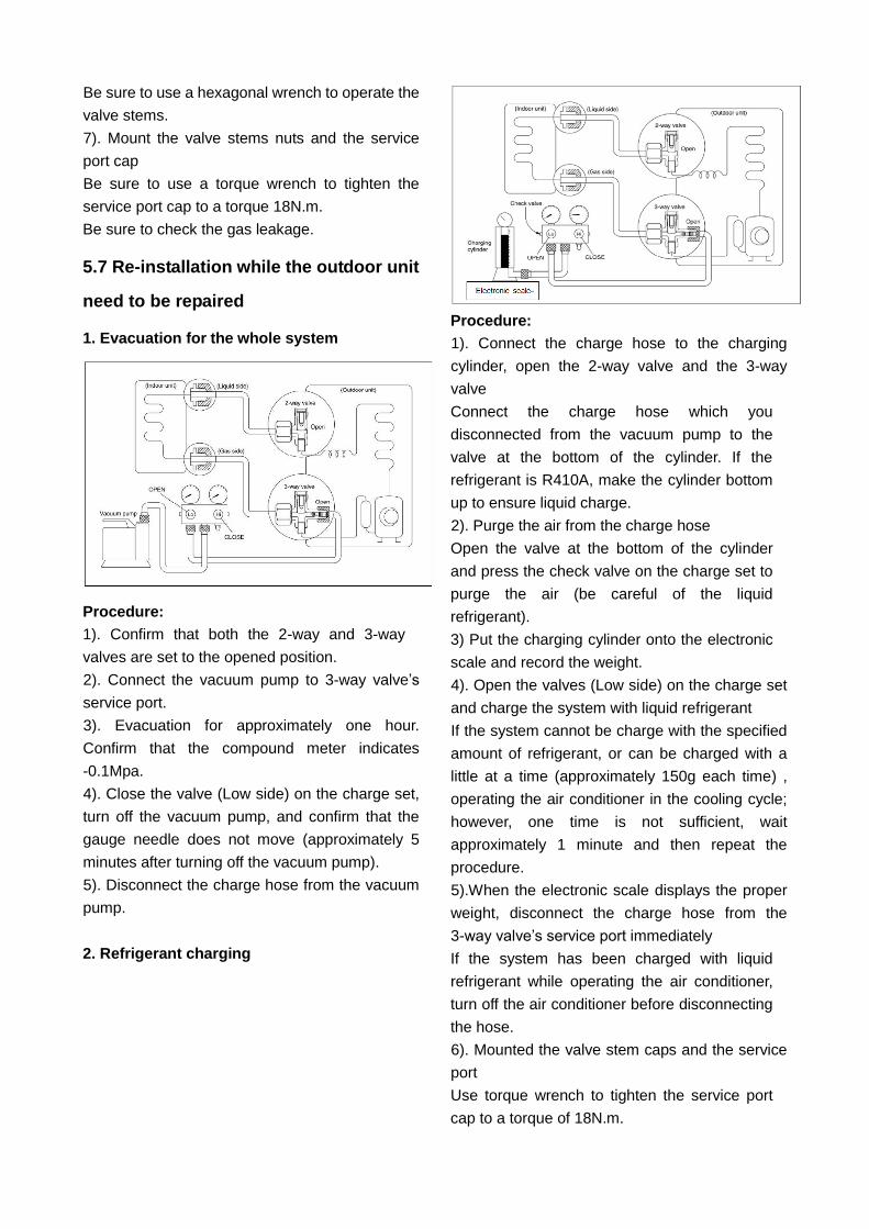
5.7 Re-installation while the outdoor unit
need to be repaired
1. Evacuation for the whole system
Procedure:
1). Confirm that both the 2-way and 3-way
valves are set to the opened position.
2). Connect the vacuum pump to 3-way valve’s
service port.
3). Evacuation for approximately one hour.
Confirm that the compound meter indicates
-0.1Mpa.
4). Close the valve (Low side) on the charge set,
turn off the vacuum pump, and confirm that the
gauge needle does not move (approximately 5
minutes after turning off the vacuum pump).
5). Disconnect the charge hose from the vacuum
pump.
2. Refrigerant charging
Procedure:
1). Connect the charge hose to the charging
cylinder, open the 2-way valve and the 3-way
valve
Connect the charge hose which you
disconnected from the vacuum pump to the
valve at the bottom of the cylinder. If the
refrigerant is R410A, make the cylinder bottom
up to ensure liquid charge.
2). Purge the air from the charge hose
Open the valve at the bottom of the cylinder
and press the check valve on the charge set to
purge the air (be careful of the liquid
refrigerant).
3) Put the charging cylinder onto the electronic
scale and record the weight.
4). Open the valves (Low side) on the charge set
and charge the system with liquid refrigerant
If the system cannot be charge with the specified
amount of refrigerant, or can be charged with a
little at a time (approximately 150g each time) ,
operating the air conditioner in the cooling cycle;
however, one time is not sufficient, wait
approximately 1 minute and then repeat the
procedure.
5).When the electronic scale displays the proper
weight, disconnect the charge hose from the
3-way valve’s service port immediately
If the system has been charged with liquid
refrigerant while operating the air conditioner,
turn off the air conditioner before disconnecting
the hose.
6). Mounted the valve stem caps and the service
port
Use torque wrench to tighten the service port
cap to a torque of 18N.m.
Be sure to check for gas leakage
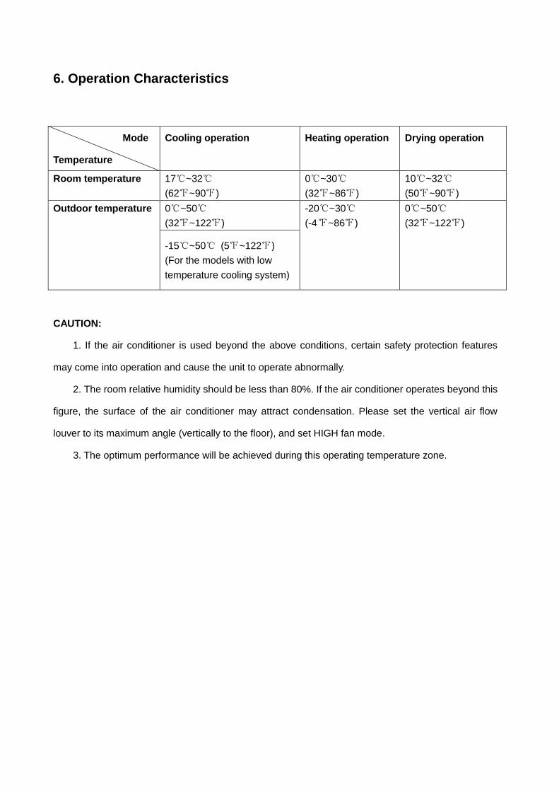
6. Operation Characteristics
Mode
Temperature
Cooling operation Heating operation Drying operation
Room temperature 17℃~32℃
(62℉~90℉)
0℃~30℃
(32℉~86℉)
10℃~32℃
(50℉~90℉)
Outdoor temperature 0℃~50℃
(32℉~122℉)
-20℃~30℃
(-4℉~86℉)
0℃~50℃
(32℉~122℉)
-15℃~50℃ (5℉~122℉)
(For the models with low
temperature cooling system)
CAUTION:
1. If the air conditioner is used beyond the above conditions, certain safety protection features
may come into operation and cause the unit to operate abnormally.
2. The room relative humidity should be less than 80%. If the air conditioner operates beyond this
figure, the surface of the air conditioner may attract condensation. Please set the vertical air flow
louver to its maximum angle (vertically to the floor), and set HIGH fan mode.
3. The optimum performance will be achieved during this operating temperature zone.
7. Electronic function
7.1 Abbreviation
T1: Indoor room temperature
T2: Coil temperature of evaporator
T3: Coil temperature of condenser
T4: Outdoor ambient temperature
T5: Compressor discharge temperature
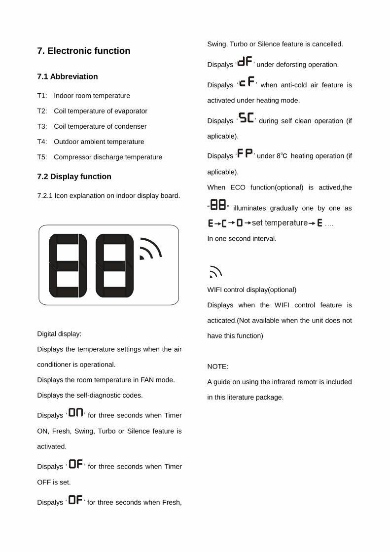
7.2 Display function
7.2.1 Icon explanation on indoor display board.
Digital display:
Displays the temperature settings when the air
conditioner is operational.
Displays the room temperature in FAN mode.
Displays the self-diagnostic codes.
Dispalys ‘ ’ for three seconds when Timer
ON, Fresh, Swing, Turbo or Silence feature is
activated.
Dispalys ‘ ’ for three seconds when Timer
OFF is set.
Dispalys ‘ ’ for three seconds when Fresh,
Swing, Turbo or Silence feature is cancelled.
Dispalys ‘ ’ under deforsting operation.
Dispalys ‘ ’ when anti-cold air feature is
activated under heating mode.
Dispalys ‘ ’ during self clean operation (if
aplicable).
Dispalys ‘ ’ under 8℃ heating operation (if
aplicable).
When ECO function(optional) is actived,the
“ ” illuminates gradually one by one as
In one second interval.
WIFI control display(optional)
Displays when the WIFI control feature is
acticated.(Not available when the unit does not
have this function)
NOTE:
A guide on using the infrared remotr is included
in this literature package.
7.3 Main Protection
7.3.1 Three minutes delay at restart for
compressor
Less than 1 minute delay for the 1st time
stand-up and 3 minutes delay for others.
7.3.2 Temperature protection of compressor
top
The unit will stop working when the compressor
top temp. protector cut off, and will restart after
the compressor top temp. protector restart.
7.3.3 Temperature protection of compressor
discharge
Compressor discharge temp. T5>115℃ for 5s,
compressor stops.
7.3.4 Fan speed is out of control
When indoor fan speed keeps too low
(300RPM) for certain time, the unit will stop and
the LED will display the failure
7.3.5 Inverter module protection
The Inverter module has a protection function
about current, voltage and temperature. If these
protections happen, the corresponding code
will display on indoor unit and the unit will stop
working.
7.3.6 Indoor fan delayed open function
When the unit starts up, the louver will be active
immediately and the indoor fan will open 7s
later.
If the unit runs in heating mode, the indoor fan
will be also controlled by anti-cold wind
function.
7.3.7 Compressor preheating functions
Preheating permitting condition:
When T4(outdoor ambient temperature)<3°C,
the preheating function will be activated.
7.3.8 Sensor protection at open circuit and
breaking disconnection.
When there’s only one temperature sensor in
malfunction , the air conditioner will keep
working but show the error code, in case of any
emergency use.
When there’s more than one temperature
sensor in malfunction, the air conditioner will
stop working
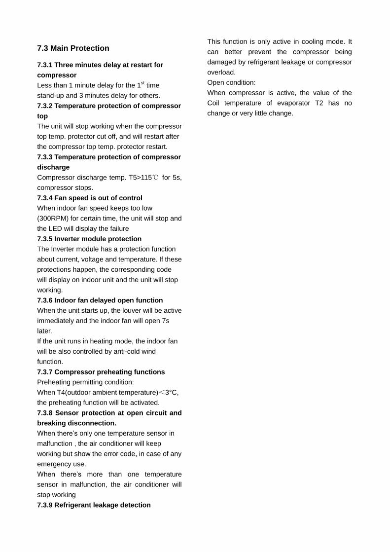
7.3.9 Refrigerant leakage detection
This function is only active in cooling mode. It
can better prevent the compressor being
damaged by refrigerant leakage or compressor
overload.
Open condition:
When compressor is active, the value of the
Coil temperature of evaporator T2 has no
change or very little change.
7.4 Operation Modes and Functions
7.4.1 Fan mode
(1) Outdoor fan and compressor stop.
(2) Temperature setting function is disabled,
and no setting temperature is displayed.
(3) Indoor fan can be set to
high/med/low/auto.
(4) The louver operates same as in cooling
mode.
(5) Auto fan:
a
b
c
d
T1
e
7.4.2 Cooling Mode
7.4.2.1 Compressor running rules
When T1-Ts<-2℃, the compressor will stop,
when T1—TS>-0.5℃,the compressor will be
activated.
When the AC run in mute mode, the
compressor will run with low frequency.
When the current is more than setting value,
the current protection function will be activated,
and the compressor will stop.
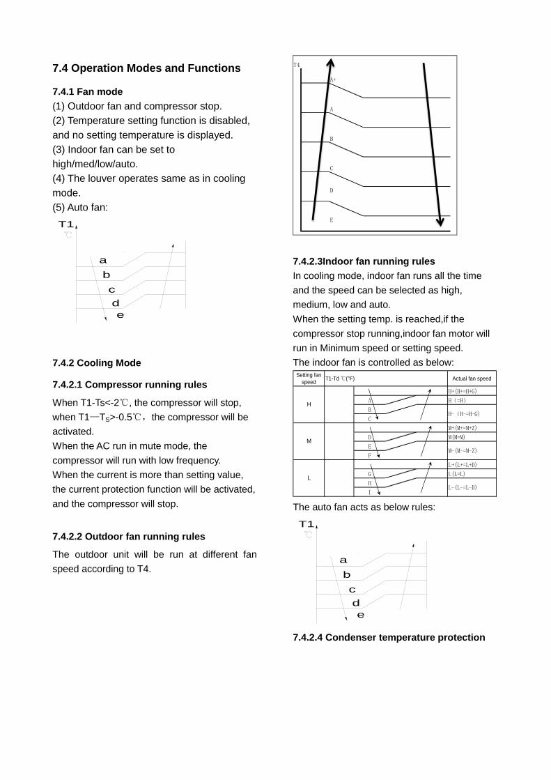
7.4.2.2 Outdoor fan running rules
The outdoor unit will be run at different fan
speed according to T4.
T4
A+
A
B
C
D
E
7.4.2.3Indoor fan running rules
In cooling mode, indoor fan runs all the time
and the speed can be selected as high,
medium, low and auto.
When the setting temp. is reached,if the
compressor stop running,indoor fan motor will
run in Minimum speed or setting speed.
The indoor fan is controlled as below: Setting fan
speedActual fan speed
H+(H+=H+G)
A H(=H)
B
C
M+(M+=M+Z)
D M(M=M)
E
F
L+(L+=L+D)
G L(L=L)
H
I
T1-Td ℃(°F)
L
L-(L-=L-D)
H
H-(H-=H-G)
M
M-(M-=M-Z)
The auto fan acts as below rules:
a
b
c
d
T1
e
7.4.2.4 Condenser temperature protection
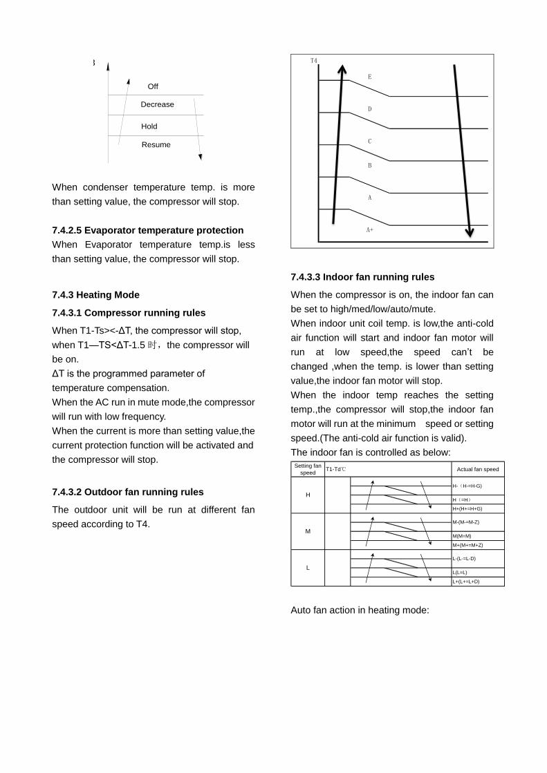
T3
Resume
Off
Decrease
Hold
When condenser temperature temp. is more
than setting value, the compressor will stop.
7.4.2.5 Evaporator temperature protection
When Evaporator temperature temp.is less
than setting value, the compressor will stop.
7.4.3 Heating Mode
7.4.3.1 Compressor running rules
When T1-Ts><-ΔT, the compressor will stop,
when T1—TS<ΔT-1.5 时,the compressor will
be on.
ΔT is the programmed parameter of
temperature compensation.
When the AC run in mute mode,the compressor
will run with low frequency.
When the current is more than setting value,the
current protection function will be activated and
the compressor will stop.
7.4.3.2 Outdoor fan running rules
The outdoor unit will be run at different fan
speed according to T4.
T4
E
D
C
B
A
A+
7.4.3.3 Indoor fan running rules
When the compressor is on, the indoor fan can
be set to high/med/low/auto/mute.
When indoor unit coil temp. is low,the anti-cold
air function will start and indoor fan motor will
run at low speed,the speed can’t be
changed ,when the temp. is lower than setting
value,the indoor fan motor will stop.
When the indoor temp reaches the setting
temp.,the compressor will stop,the indoor fan
motor will run at the minimum speed or setting
speed.(The anti-cold air function is valid).
The indoor fan is controlled as below:
Setting fan
speedActual fan speed
H(=H)
H+(H+=H+G)
M(M=M)
M+(M+=M+Z)
L(L=L)
L+(L+=L+D)
H-(H-=H-G)
M-(M-=M-Z)
L-(L-=L-D)
T1-Td℃
L
H
M
-
Auto fan action in heating mode:
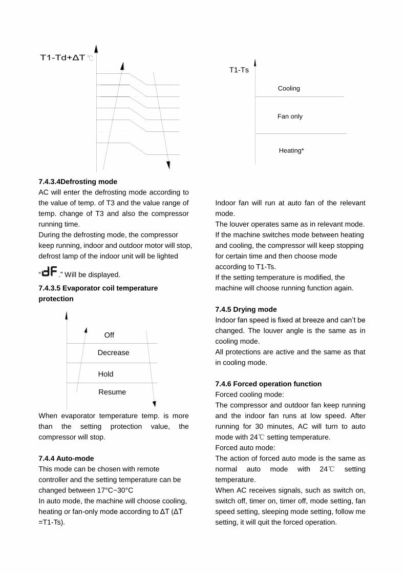
T1-Td+ΔT
7.4.3.4Defrosting mode
AC will enter the defrosting mode according to
the value of temp. of T3 and the value range of
temp. change of T3 and also the compressor
running time.
During the defrosting mode, the compressor
keep running, indoor and outdoor motor will stop,
defrost lamp of the indoor unit will be lighted
“ .” Will be displayed.
7.4.3.5 Evaporator coil temperature
protection
T2
Resume
Off
Decrease
Hold
When evaporator temperature temp. is more
than the setting protection value, the
compressor will stop.
7.4.4 Auto-mode
This mode can be chosen with remote
controller and the setting temperature can be
changed between 17°C~30°C
In auto mode, the machine will choose cooling,
heating or fan-only mode according to ΔT (ΔT
=T1-Ts).
T1-Ts
Cooling
Heating*
Fan only
Indoor fan will run at auto fan of the relevant
mode.
The louver operates same as in relevant mode.
If the machine switches mode between heating
and cooling, the compressor will keep stopping
for certain time and then choose mode
according to T1-Ts.
If the setting temperature is modified, the
machine will choose running function again.
7.4.5 Drying mode
Indoor fan speed is fixed at breeze and can’t be
changed. The louver angle is the same as in
cooling mode.
All protections are active and the same as that
in cooling mode.
7.4.6 Forced operation function
Forced cooling mode:
The compressor and outdoor fan keep running
and the indoor fan runs at low speed. After
running for 30 minutes, AC will turn to auto
mode with 24℃ setting temperature.
Forced auto mode:
The action of forced auto mode is the same as
normal auto mode with 24℃ setting
temperature.
When AC receives signals, such as switch on,
switch off, timer on, timer off, mode setting, fan
speed setting, sleeping mode setting, follow me
setting, it will quit the forced operation.
7.4.7 Auto-Restart function
The indoor unit is equipped with auto-restart
function, which is carried out through an
auto-restart module. In case of a sudden power
failure, the module memorizes the setting
conditions before the power failure. The unit will
resume the previous operation setting (not
including swing function) automatically after 3
minutes when power returns.
If the memorization condition is forced cooling
mode, the unit will run in cooling mode for 30
minutes and turn to auto mode as 24℃ setting
temp.
If AC is off before power off and AC is required
to start up now, the compressor will have 1
minute delay when power on. Other conditions,
the compressor will have 3 minutes delay when
restarts.
7.4.8 8℃ Heating(optional)
When the compressor is running, the indoor fan
motor will run without anti-cold air function.
When the compressor is off, the indoor fan
motor is off .
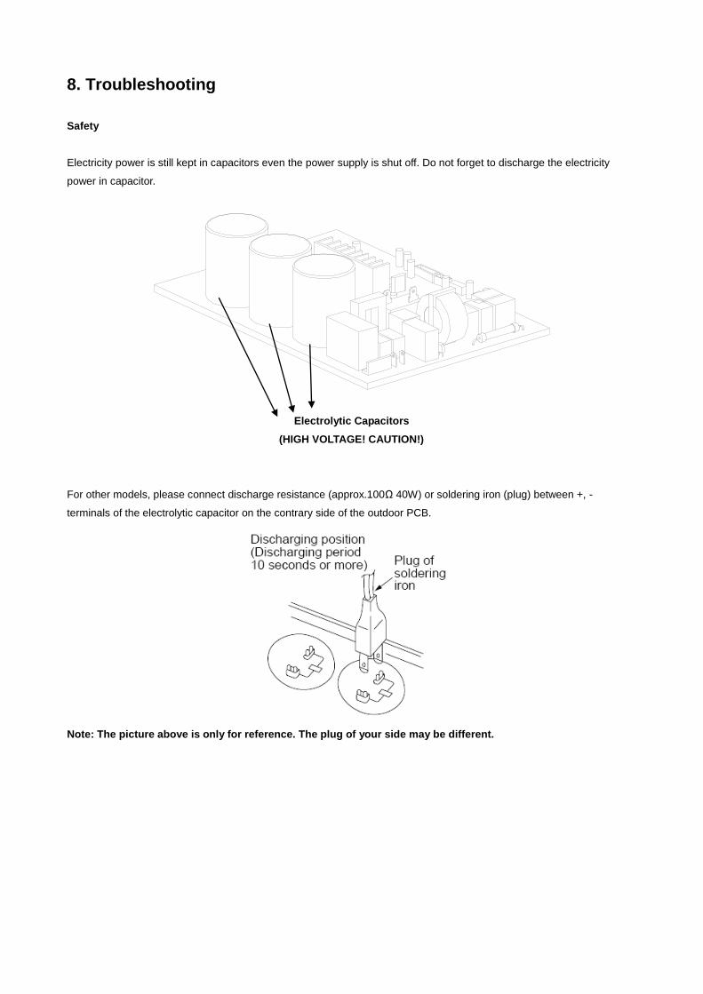
8. Troubleshooting
Safety
Electricity power is still kept in capacitors even the power supply is shut off. Do not forget to discharge the electricity
power in capacitor.
Electrolytic Capacitors
(HIGH VOLTAGE! CAUTION!)
For other models, please connect discharge resistance (approx.100Ω 40W) or soldering iron (plug) between +, -
terminals of the electrolytic capacitor on the contrary side of the outdoor PCB.
Note: The picture above is only for reference. The plug of your side may be different.
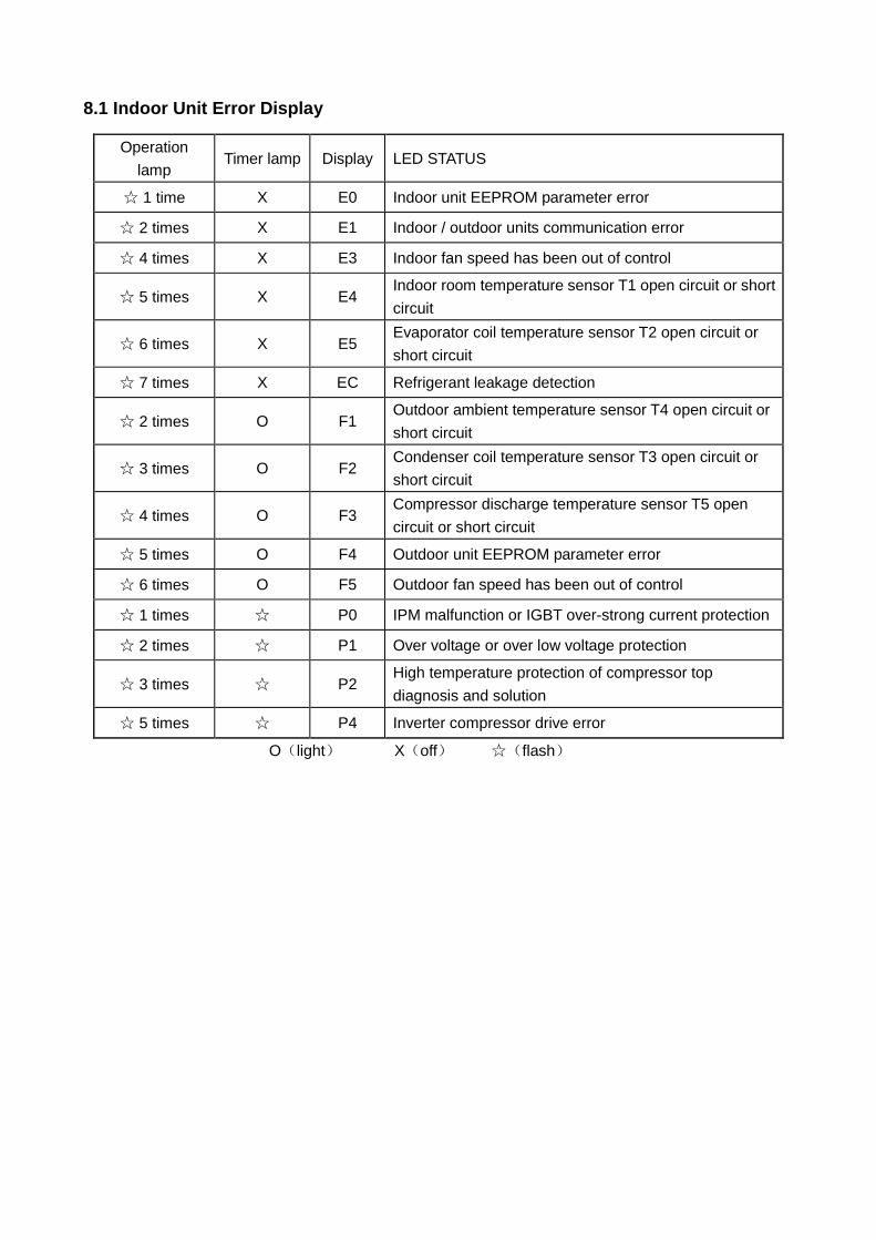
8.1 Indoor Unit Error Display
Operation
lamp Timer lamp Display LED STATUS
☆ 1 time X E0 Indoor unit EEPROM parameter error
☆ 2 times X E1 Indoor / outdoor units communication error
☆ 4 times X E3 Indoor fan speed has been out of control
☆ 5 times X E4 Indoor room temperature sensor T1 open circuit or short
circuit
☆ 6 times X E5 Evaporator coil temperature sensor T2 open circuit or
short circuit
☆ 7 times X EC Refrigerant leakage detection
☆ 2 times O F1 Outdoor ambient temperature sensor T4 open circuit or
short circuit
☆ 3 times O F2 Condenser coil temperature sensor T3 open circuit or
short circuit
☆ 4 times O F3 Compressor discharge temperature sensor T5 open
circuit or short circuit
☆ 5 times O F4 Outdoor unit EEPROM parameter error
☆ 6 times O F5 Outdoor fan speed has been out of control
☆ 1 times ☆ P0 IPM malfunction or IGBT over-strong current protection
☆ 2 times ☆ P1 Over voltage or over low voltage protection
☆ 3 times ☆ P2 High temperature protection of compressor top
diagnosis and solution
☆ 5 times ☆ P4 Inverter compressor drive error
O(light) X(off) ☆(flash)
8.2 Trouble shooting
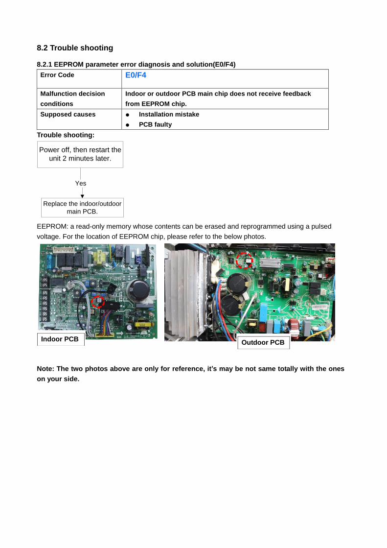
8.2.1 EEPROM parameter error diagnosis and solution(E0/F4)
Error Code E0/F4
Malfunction decision
conditions
Indoor or outdoor PCB main chip does not receive feedback
from EEPROM chip.
Supposed causes ● Installation mistake
● PCB faulty
Trouble shooting:
Yes
Replace the indoor/outdoor
main PCB.
Power off, then restart the
unit 2 minutes later.
EEPROM: a read-only memory whose contents can be erased and reprogrammed using a pulsed
voltage. For the location of EEPROM chip, please refer to the below photos.
Note: The two photos above are only for reference, it’s may be not same totally with the ones
on your side.
Indoor PCB Outdoor PCB
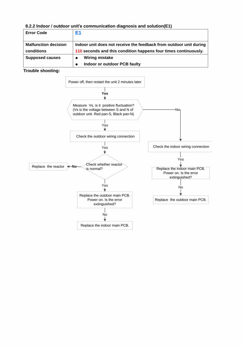
8.2.2 Indoor / outdoor unit’s communication diagnosis and solution(E1)
Error Code E1
Malfunction decision
conditions
Indoor unit does not receive the feedback from outdoor unit during
110 seconds and this condition happens four times continuously.
Supposed causes ● Wiring mistake
● Indoor or outdoor PCB faulty
Trouble shooting:
Measure Vs, is it positive fluctuation?
(Vs is the voltage between S and N of
outdoor unit. Red pan-S, Black pan-N)
Measure Vs, is it positive fluctuation?
(Vs is the voltage between S and N of
outdoor unit. Red pan-S, Black pan-N)
Yes
Power off, then restart the unit 2 minutes laterPower off, then restart the unit 2 minutes later
No
Replace the outdoor main PCB.
Power on. Is the error
extinguished?
Replace the outdoor main PCB.
Power on. Is the error
extinguished?
Check the outdoor wiring connection Check the outdoor wiring connection
Replace the indoor main PCB.
Power on. Is the error
extinguished?
Replace the indoor main PCB.
Power on. Is the error
extinguished?
Yes
Replace the outdoor main PCB.Replace the outdoor main PCB.
No
Replace the indoor main PCB.Replace the indoor main PCB.
No
Check the indoor wiring connection Check the indoor wiring connectionYes
Yes
Check whether reactor
is normal?
Check whether reactor
is normal?
Yes
Replace the reactorReplace the reactor No
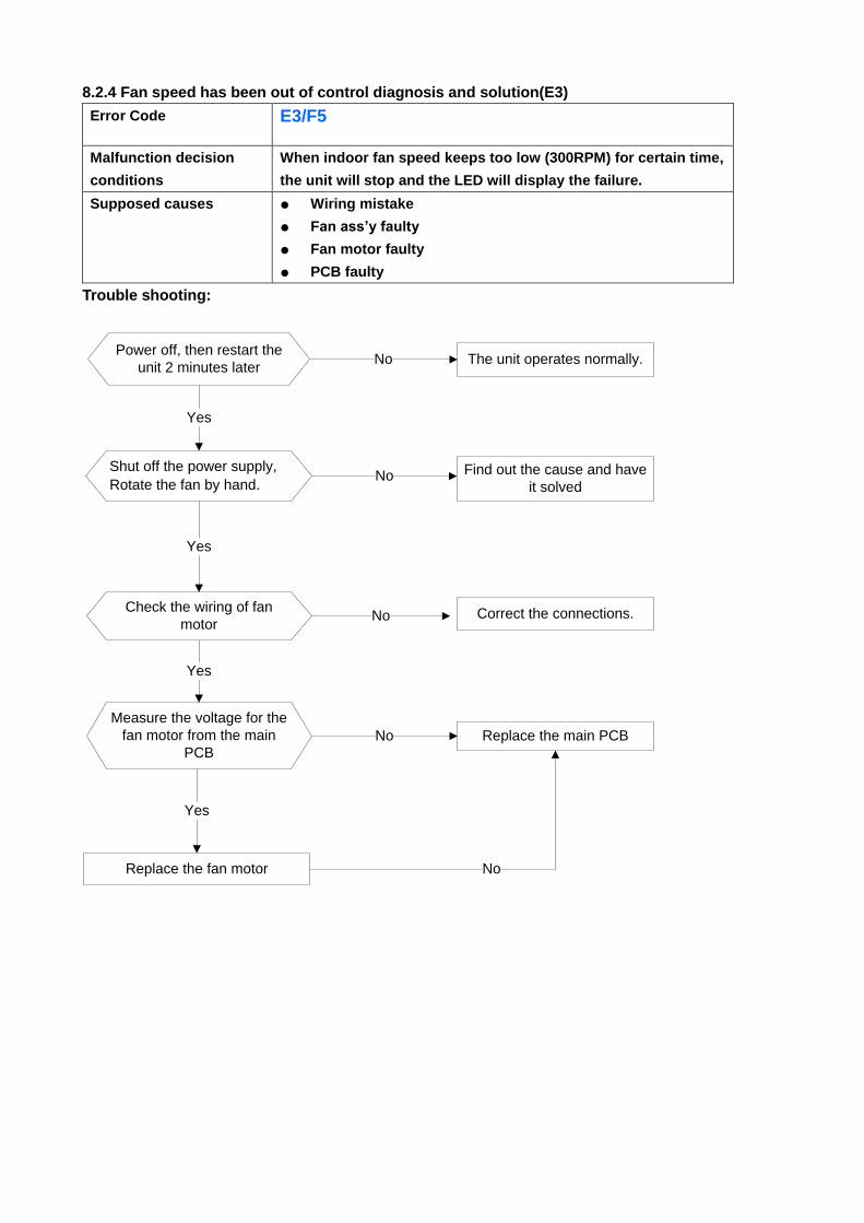
8.2.4 Fan speed has been out of control diagnosis and solution(E3)
Error Code E3/F5
Malfunction decision
conditions
When indoor fan speed keeps too low (300RPM) for certain time,
the unit will stop and the LED will display the failure.
Supposed causes ● Wiring mistake
● Fan ass’y faulty
● Fan motor faulty
● PCB faulty
Trouble shooting:
Power off, then restart the
unit 2 minutes later
Shut off the power supply,
Rotate the fan by hand.
The unit operates normally.
Find out the cause and have
it solved
Check the wiring of fan
motor
No
Yes
No
Correct the connections.No
NoReplace the fan motor
Yes
Yes
Measure the voltage for the
fan motor from the main
PCB
Yes
Replace the main PCBNo
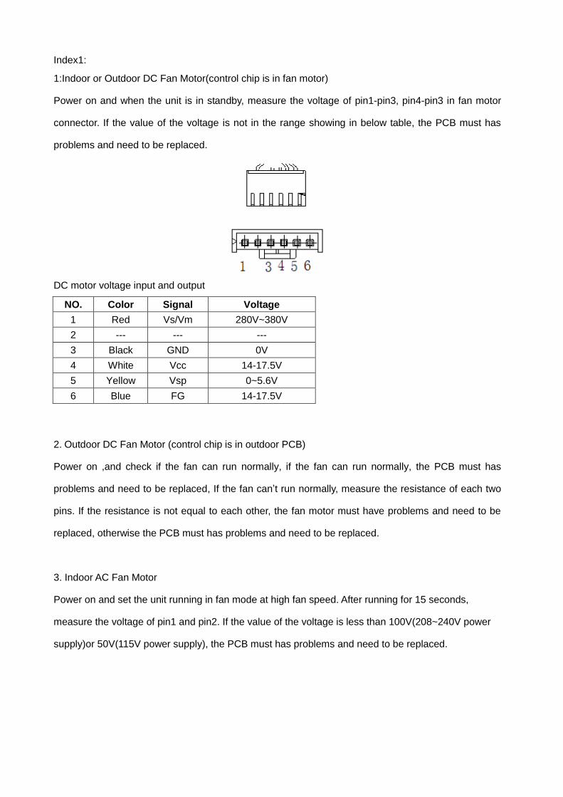
Index1:
1:Indoor or Outdoor DC Fan Motor(control chip is in fan motor)
Power on and when the unit is in standby, measure the voltage of pin1-pin3, pin4-pin3 in fan motor
connector. If the value of the voltage is not in the range showing in below table, the PCB must has
problems and need to be replaced.
DC motor voltage input and output
NO. Color Signal Voltage
1 Red Vs/Vm 280V~380V
2 --- --- ---
3 Black GND 0V
4 White Vcc 14-17.5V
5 Yellow Vsp 0~5.6V
6 Blue FG 14-17.5V
2. Outdoor DC Fan Motor (control chip is in outdoor PCB)
Power on ,and check if the fan can run normally, if the fan can run normally, the PCB must has
problems and need to be replaced, If the fan can’t run normally, measure the resistance of each two
pins. If the resistance is not equal to each other, the fan motor must have problems and need to be
replaced, otherwise the PCB must has problems and need to be replaced.
3. Indoor AC Fan Motor
Power on and set the unit running in fan mode at high fan speed. After running for 15 seconds,
measure the voltage of pin1 and pin2. If the value of the voltage is less than 100V(208~240V power
supply)or 50V(115V power supply), the PCB must has problems and need to be replaced.
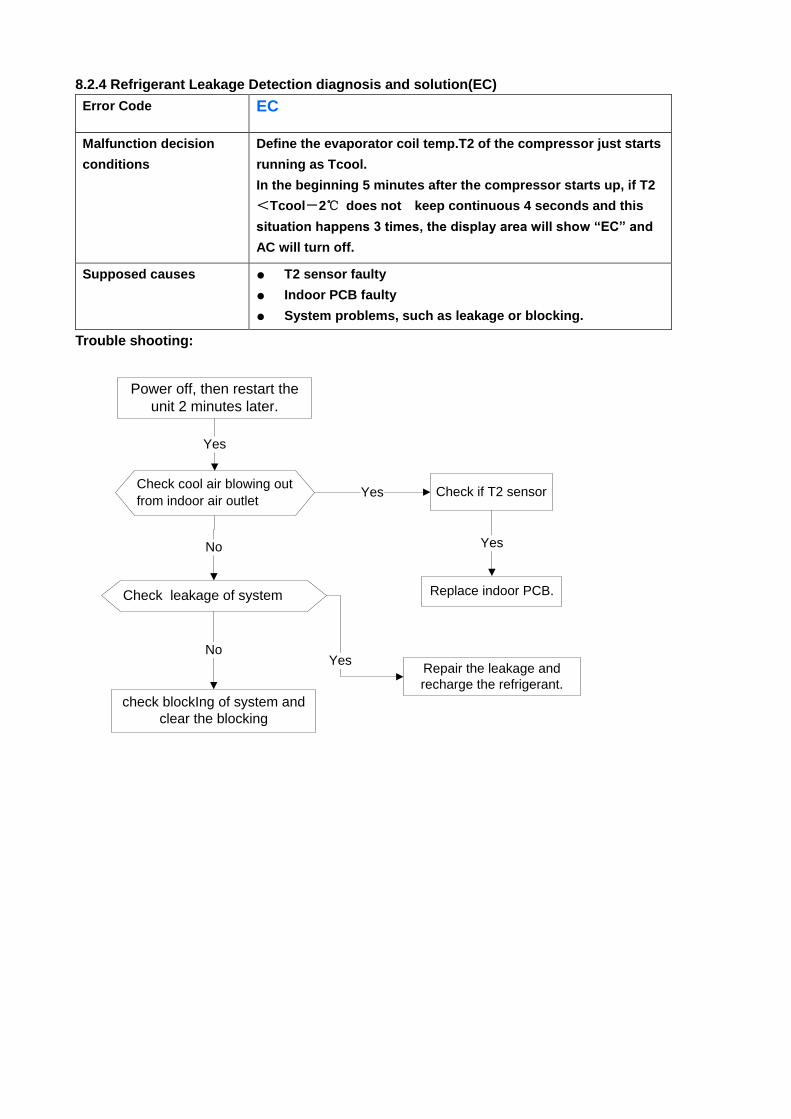
8.2.4 Refrigerant Leakage Detection diagnosis and solution(EC)
Error Code EC
Malfunction decision
conditions
Define the evaporator coil temp.T2 of the compressor just starts
running as Tcool.
In the beginning 5 minutes after the compressor starts up, if T2
<Tcool-2℃ does not keep continuous 4 seconds and this
situation happens 3 times, the display area will show “EC” and
AC will turn off.
Supposed causes ● T2 sensor faulty
● Indoor PCB faulty
● System problems, such as leakage or blocking.
Trouble shooting:
Check cool air blowing out
from indoor air outlet
Yes
Yes Check if T2 sensor
No
Check leakage of system
No
Power off, then restart the
unit 2 minutes later.
Replace indoor PCB.
Yes
Repair the leakage and
recharge the refrigerant.
Yes
check blockIng of system and
clear the blocking
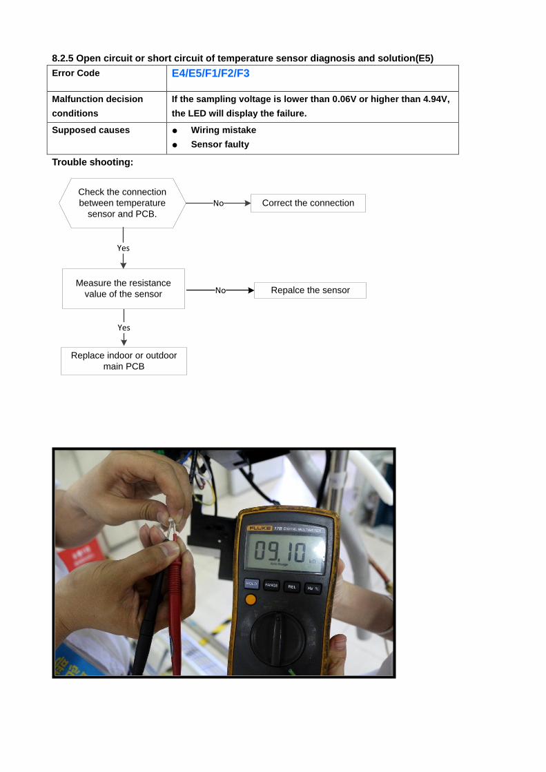
8.2.5 Open circuit or short circuit of temperature sensor diagnosis and solution(E5)
Error Code E4/E5/F1/F2/F3
Malfunction decision
conditions
If the sampling voltage is lower than 0.06V or higher than 4.94V,
the LED will display the failure.
Supposed causes ● Wiring mistake
● Sensor faulty
● PCB faulty Trouble shooting:
Check the connection
between temperature
sensor and PCB.
Correct the connectionNo
Yes
Replace indoor or outdoor
main PCB
Measure the resistance
value of the sensor Repalce the sensorNo
Yes
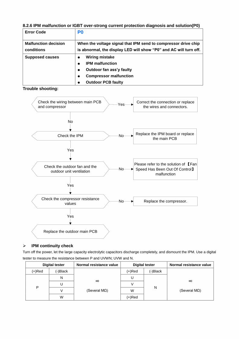
8.2.6 IPM malfunction or IGBT over-strong current protection diagnosis and solution(P0)
Error Code P0
Malfunction decision
conditions
When the voltage signal that IPM send to compressor drive chip
is abnormal, the display LED will show “P0” and AC will turn off.
Supposed causes ● Wiring mistake
● IPM malfunction
● Outdoor fan ass’y faulty
● Compressor malfunction
● Outdoor PCB faulty
Trouble shooting:
Check the wiring between main PCB
and compressor
Correct the connection or replace
the wires and connectors.Yes
No
Check the IPM No
Yes
Replace the IPM board or replace
the main PCB
Check the outdoor fan and the
outdoor unit ventilationNo
Please refer to the solution of 【Fan
Speed Has Been Out Of Control】malfunction
Yes
Check the compressor resistance
valuesNo Replace the compressor.
Yes
Replace the outdoor main PCB
IPM continuity check
Turn off the power, let the large capacity electrolytic capacitors discharge completely, and dismount the IPM. Use a digital
tester to measure the resistance between P and UVWN; UVW and N.
Digital tester Normal resistance value Digital tester Normal resistance value
(+)Red (-)Black
∞
(Several MΩ)
(+)Red (-)Black
∞
(Several MΩ) P
N U
N U V
V W
W (+)Red
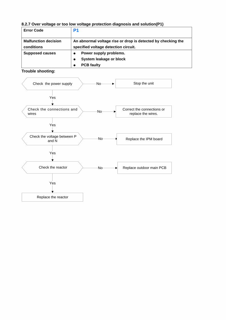
8.2.7 Over voltage or too low voltage protection diagnosis and solution(P1)
Error Code P1
Malfunction decision
conditions
An abnormal voltage rise or drop is detected by checking the
specified voltage detection circuit.
Supposed causes ● Power supply problems.
● System leakage or block
● PCB faulty
Trouble shooting:
Check the power supply
Check the connections and
wires
Stop the unitNo
Yes
NoCorrect the connections or
replace the wires.
Yes
Replace the reactor
Yes
No Replace the IPM board Check the voltage between P
and N
Check the reactor
Yes
No Replace outdoor main PCB
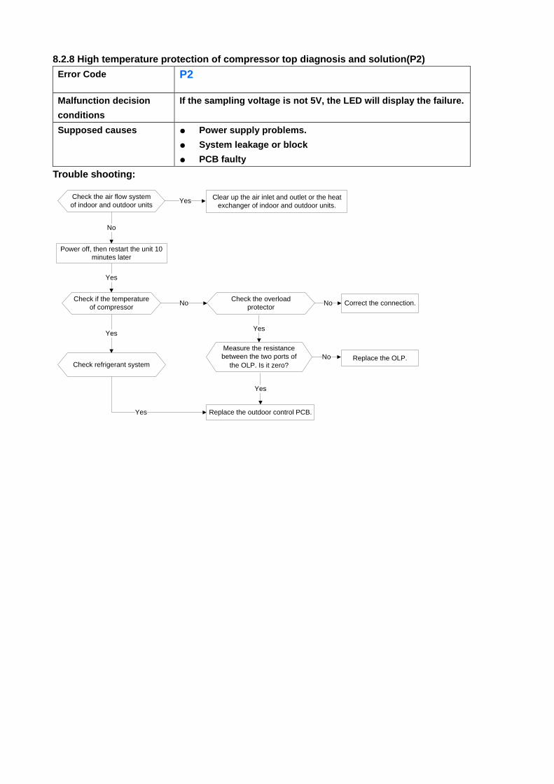
8.2.8 High temperature protection of compressor top diagnosis and solution(P2)
Error Code P2
Malfunction decision
conditions
If the sampling voltage is not 5V, the LED will display the failure.
Supposed causes ● Power supply problems.
● System leakage or block
● PCB faulty
Trouble shooting:
Check the air flow system
of indoor and outdoor units Clear up the air inlet and outlet or the heat
exchanger of indoor and outdoor units.Yes
No
Yes
Yes
Power off, then restart the unit 10
minutes later
Check if the temperature
of compressor No
Check refrigerant system
Yes
Check the overload
protectorCorrect the connection.No
Measure the resistance
between the two ports of
the OLP. Is it zero?
Yes
Replace the OLP.No
Replace the outdoor control PCB.
Yes
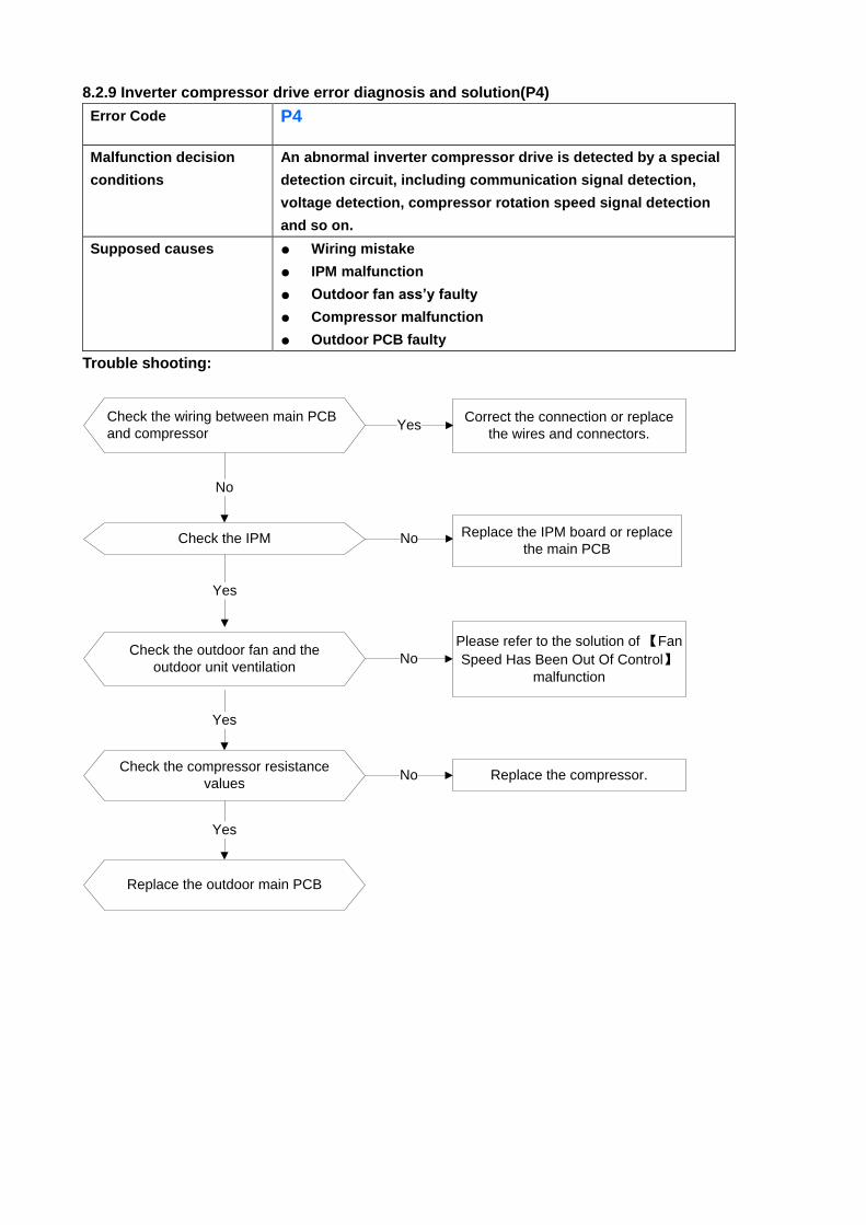
8.2.9 Inverter compressor drive error diagnosis and solution(P4)
Error Code P4
Malfunction decision
conditions
An abnormal inverter compressor drive is detected by a special
detection circuit, including communication signal detection,
voltage detection, compressor rotation speed signal detection
and so on.
Supposed causes ● Wiring mistake
● IPM malfunction
● Outdoor fan ass’y faulty
● Compressor malfunction
● Outdoor PCB faulty
Trouble shooting:
Check the wiring between main PCB
and compressor
Correct the connection or replace
the wires and connectors.Yes
No
Check the IPM No
Yes
Replace the IPM board or replace
the main PCB
Check the outdoor fan and the
outdoor unit ventilationNo
Please refer to the solution of 【Fan
Speed Has Been Out Of Control】malfunction
Yes
Check the compressor resistance
valuesNo Replace the compressor.
Yes
Replace the outdoor main PCB
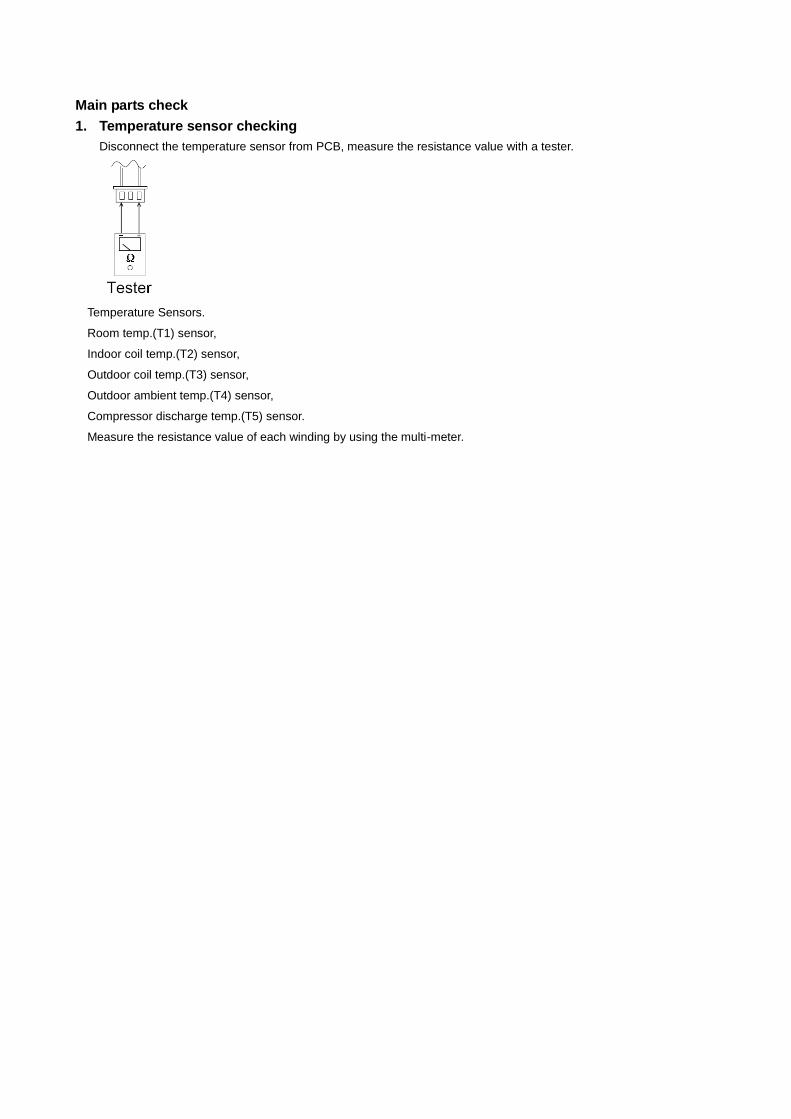
Main parts check
1. Temperature sensor checking
Disconnect the temperature sensor from PCB, measure the resistance value with a tester.
Temperature Sensors.
Room temp.(T1) sensor,
Indoor coil temp.(T2) sensor,
Outdoor coil temp.(T3) sensor,
Outdoor ambient temp.(T4) sensor,
Compressor discharge temp.(T5) sensor.
Measure the resistance value of each winding by using the multi-meter.
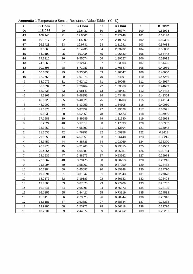
Appendix 1 Temperature Sensor Resistance Value Table (℃--K)
℃ K Ohm ℃ K Ohm ℃ K Ohm ℃ K Ohm
-20 115.266 20 12.6431 60 2.35774 100 0.62973
-19 108.146 21 12.0561 61 2.27249 101 0.61148
-18 101.517 22 11.5000 62 2.19073 102 0.59386
-17 96.3423 23 10.9731 63 2.11241 103 0.57683
-16 89.5865 24 10.4736 64 2.03732 104 0.56038
-15 84.2190 25 10.000 65 1.96532 105 0.54448
-14 79.3110 26 9.55074 66 1.89627 106 0.52912
-13 74.5360 27 9.12445 67 1.83003 107 0.51426
-12 70.1698 28 8.71983 68 1.76647 108 0.49989
-11 66.0898 29 8.33566 69 1.70547 109 0.48600
-10 62.2756 30 7.97078 70 1.64691 110 0.47256
-9 58.7079 31 7.62411 71 1.59068 111 0.45957
-8 56.3694 32 7.29464 72 1.53668 112 0.44699
-7 52.2438 33 6.98142 73 1.48481 113 0.43482
-6 49.3161 34 6.68355 74 1.43498 114 0.42304
-5 46.5725 35 6.40021 75 1.38703 115 0.41164
-4 44.0000 36 6.13059 76 1.34105 116 0.40060
-3 41.5878 37 5.87359 77 1.29078 117 0.38991
-2 39.8239 38 5.62961 78 1.25423 118 0.37956
-1 37.1988 39 5.39689 79 1.21330 119 0.36954
0 35.2024 40 5.17519 80 1.17393 120 0.35982
1 33.3269 41 4.96392 81 1.13604 121 0.35042
2 31.5635 42 4.76253 82 1.09958 122 0.3413
3 29.9058 43 4.57050 83 1.06448 123 0.33246
4 28.3459 44 4.38736 84 1.03069 124 0.32390
5 26.8778 45 4.21263 85 0.99815 125 0.31559
6 25.4954 46 4.04589 86 0.96681 126 0.30754
7 24.1932 47 3.88673 87 0.93662 127 0.29974
8 22.5662 48 3.73476 88 0.90753 128 0.29216
9 21.8094 49 3.58962 89 0.87950 129 0.28482
10 20.7184 50 3.45097 90 0.85248 130 0.27770
11 19.6891 51 3.31847 91 0.82643 131 0.27078
12 18.7177 52 3.19183 92 0.80132 132 0.26408
13 17.8005 53 3.07075 93 0.77709 133 0.25757
14 16.9341 54 2.95896 94 0.75373 134 0.25125
15 16.1156 55 2.84421 95 0.73119 135 0.24512
16 15.3418 56 2.73823 96 0.70944 136 0.23916
17 14.6181 57 2.63682 97 0.68844 137 0.23338
18 13.9180 58 2.53973 98 0.66818 138 0.22776
19 13.2631 59 2.44677 99 0.64862 139 0.22231
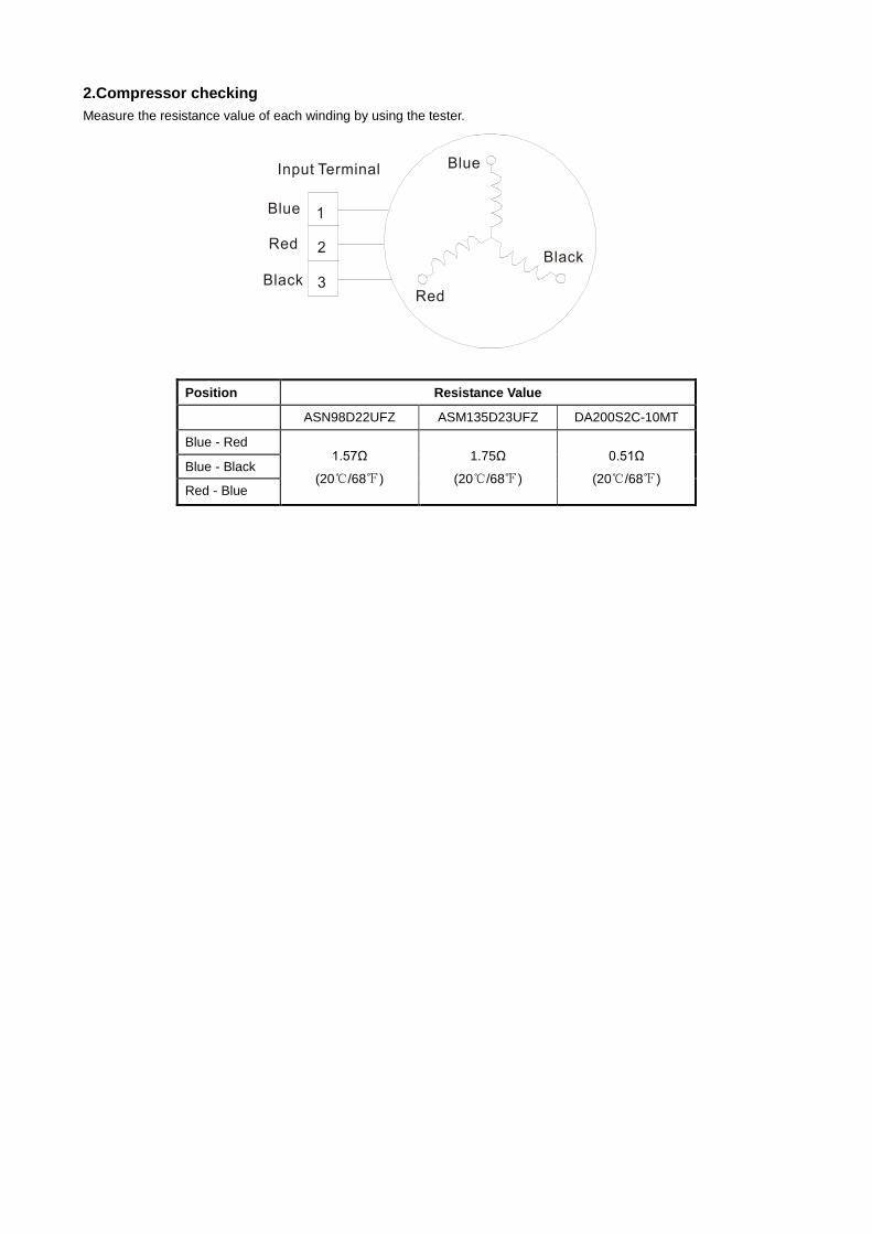
2.Compressor checking
Measure the resistance value of each winding by using the tester.
Position Resistance Value
ASN98D22UFZ ASM135D23UFZ DA200S2C-10MT
Blue - Red 1.57Ω
(20℃/68℉)
1.75Ω
(20℃/68℉)
0.51Ω
(20℃/68℉) Blue - Black
Red - Blue