Embed Size (px)
Citation preview

MATERIALS SCIENCES NORTHWEST, INC.P.O. BOX 1412
CORVALLIS, OREGON 97330
P.O. BOX 865SANMARCOS, CALIFORNIA 92069
(714) 744-7648
PROPERTY AND PRODUCTIVITY IMPROVEMENTS
IN ELECTROSLAG AND ELECTROGAS WELDING
FINAL REPORT
JANUARY 1980
G.H. Reynolds; Ph.D.,P.E.Principal Investigator

Report Documentation Page Form ApprovedOMB No. 0704-0188
Public reporting burden for the collection of information is estimated to average 1 hour per response, including the time for reviewing instructions, searching existing data sources, gathering andmaintaining the data needed, and completing and reviewing the collection of information. Send comments regarding this burden estimate or any other aspect of this collection of information,including suggestions for reducing this burden, to Washington Headquarters Services, Directorate for Information Operations and Reports, 1215 Jefferson Davis Highway, Suite 1204, ArlingtonVA 22202-4302. Respondents should be aware that notwithstanding any other provision of law, no person shall be subject to a penalty for failing to comply with a collection of information if itdoes not display a currently valid OMB control number.
1. REPORT DATE JAN 1980
2. REPORT TYPE N/A
3. DATES COVERED -
4. TITLE AND SUBTITLE Property and Productivity Improvements in Electroslag and Electrogas Welding
5a. CONTRACT NUMBER
5b. GRANT NUMBER
5c. PROGRAM ELEMENT NUMBER
6. AUTHOR(S) 5d. PROJECT NUMBER
5e. TASK NUMBER
5f. WORK UNIT NUMBER
7. PERFORMING ORGANIZATION NAME(S) AND ADDRESS(ES) Naval Surface Warfare Center CD Code 2230 - Design Integration ToolsBuilding 192 Room 128-9500 MacArthur Blvd Betheda, MD 20817-5700
8. PERFORMING ORGANIZATIONREPORT NUMBER
9. SPONSORING/MONITORING AGENCY NAME(S) AND ADDRESS(ES) 10. SPONSOR/MONITOR’S ACRONYM(S)
11. SPONSOR/MONITOR’S REPORT NUMBER(S)
12. DISTRIBUTION/AVAILABILITY STATEMENT Approved for public release, distribution unlimited
13. SUPPLEMENTARY NOTES
14. ABSTRACT
15. SUBJECT TERMS
16. SECURITY CLASSIFICATION OF: 17. LIMITATION OF ABSTRACT
SAR
18. NUMBEROF PAGES
97
19a. NAME OFRESPONSIBLE PERSON
a. REPORT unclassified
b. ABSTRACT unclassified
c. THIS PAGE unclassified
Standard Form 298 (Rev. 8-98) Prescribed by ANSI Std Z39-18

TABLE OF CONTENTS
FOREWORD . . . . . . . . . . . . . . . . . . . . . . . . . . . . . . . . . . . . . . . . . .
EXECUTIVE SUMMARY . . . . . . . . . . . . . . . . . . . . . . . . . . . . . . .
INTRODUCTION . . . . . . . . . . . . . . . . . . . . . . . . . . . . . . . . . . . . .
WELDING TESTS . . . . . . . . . . . . . . . . . . . . . . . . . . . . . . . . . . . . .
. . . .
. . . .
. . . .
. . . .
REFERENCES . . . . . . . . . . . . . . . . . . . . . . . . . . . . . . . . . . . . . . . . .
TABLES . . . . . . . . . . . . . . . . . . . . . . . . . . . . . . . . . . . . . . . . . . . . .
FIGURES . . . . . . . . . . . . . . . . . . . . . . . . . . . . . . . . . . . . . . . . . .
i
ii
1
9
30
33
55

The purpose of his report
FOREWORD
is to present the results of one of
the research and development programs which was initiated by the
members of the Ship Production Committee of The Society of Naval
Architects and Marine Engineers and financed largely by government
funds through a cost-sharing contract between the U.S. Maritime
Administration and Bethlehem Steel Corporation. The effort of this
project was directed to the development of improved methods and hard-
ware applicable to shipyard welding in the U.S. shipyards.
Mr. W. C. Brayton, Bethlehem Steel Corporation, was the Program
Manager; Mr.
directed the
Special
SP-7 of the
advisors in
proposals.
G. H. Reynolds of Materials Sciences Northwest, Inc.
development at Corvallis, Oregon.
acknowledgement is made to the members of Welding Panel
SNAME Ship Production Committee who served as technical
the preparation of inquiries and evaluation of subcontract
i
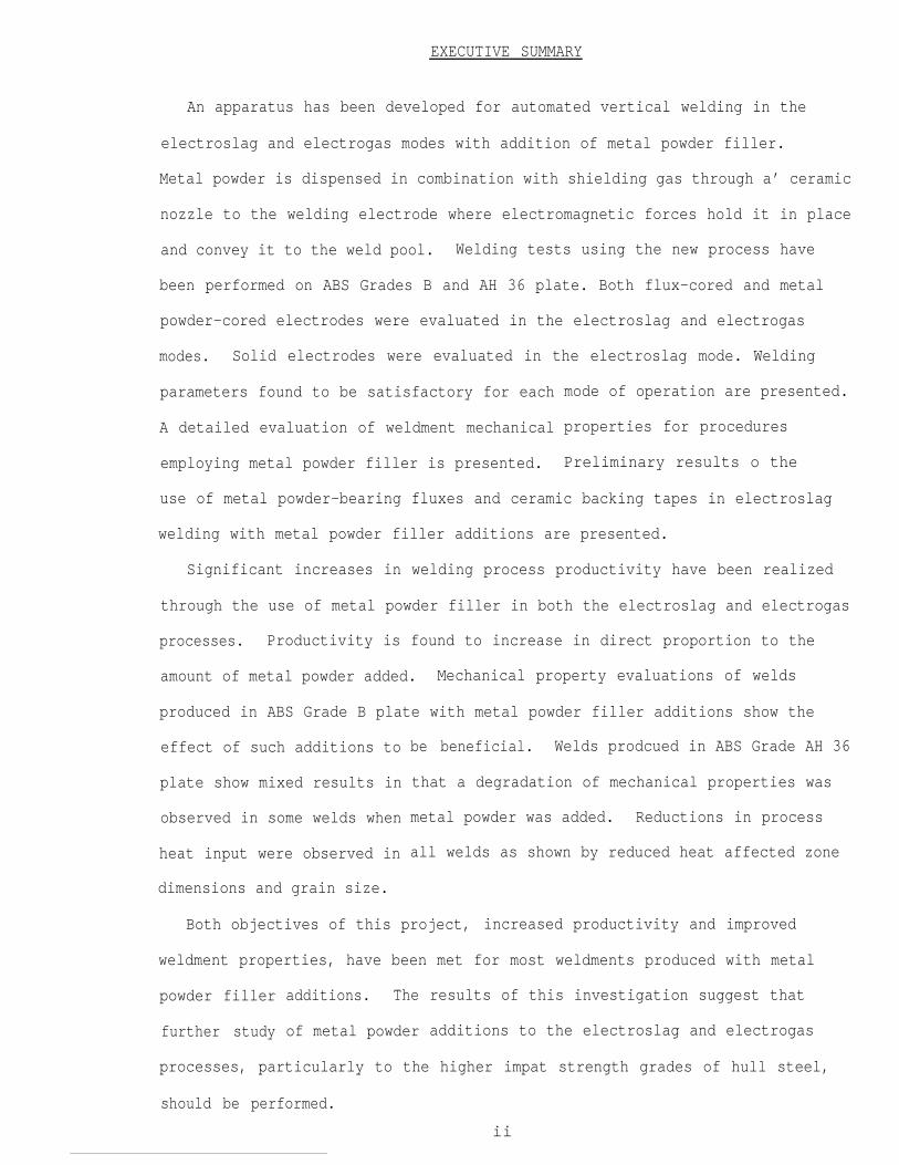
EXECUTIVE SUMMARY
An apparatus has been developed for automated vertical welding in the
electroslag and electrogas modes with addition of metal powder filler.
Metal powder is dispensed in combination with shielding gas through a’ ceramic
nozzle to the welding electrode where electromagnetic forces hold it in place
and convey it to the weld pool. Welding tests using the new process have
been performed on ABS Grades B and AH 36 plate. Both flux-cored and metal
powder-cored electrodes were evaluated in the electroslag and electrogas
modes. Solid electrodes were evaluated in the electroslag mode. Welding
parameters found to be satisfactory for each
A detailed evaluation of weldment mechanical
employing metal powder filler is presented.
mode of operation are presented.
properties for procedures
Preliminary results o the
use of metal powder-bearing fluxes and ceramic backing tapes in electroslag
welding with metal powder filler additions are presented.
Significant increases in welding process productivity have been realized
through the use of metal powder filler in both the electroslag and electrogas
processes. Productivity is found to increase in direct proportion to the
amount of metal powder added. Mechanical property evaluations of welds
produced in ABS Grade B plate with metal powder filler additions show the
effect of such additions to
plate show mixed results in
observed in some welds when
heat input were observed in
dimensions and grain size.
be beneficial. Welds prodcued in ABS Grade AH 36
that a degradation of mechanical properties was
metal powder was added. Reductions in process
all welds as shown by reduced heat affected zone
Both objectives of this project, increased productivity and improved
weldment properties, have been met for most weldments produced with metal
powder filler
further study
additions. The
of metal powder
results of this investigation suggest that
additions to the electroslag and electrogas
processes, particularly to the higher impat strength grades of hull steel,
should be performed.
ii

INTRODUCTION
This project had as its objective the development of equipment and welding
procedures for the use of metal powder filler additions in both the electro-
slag and electrogas processes. Metal powder filler additions were studied
to improve the properties of electroslag and electrogas weldments by reducing
process heat input and to improve the overall process productivity by increas-
ing the total metal deposition rate. The project began with a review of
world literature on metal powder filler additions to these processes. A comput-
erized information retrieval search of the technical literature on electroslag
and electrogas processes for the period
entries. Of these, 621 were related to
1966-1978 produced a total of 1615
electrogas and electroslag welding.
These were reviewed in detail for information relating to the use of powdered
metal filler materials and mathematical modelling techniques in electroslag
and electrogas welding. Manual review of literature published prior to 1966
and since 1978 was also performed. Three general reviews of the subject
found to be quite useful, those by Paton (l), Campbell (2) and Liby and
Olsen (3).
were
Use of Powdered Metal Filler in Electroslag Welding-Process Considerations
The origin of the concept of using powdered metal filler in the electroslag
welding process is clearly Russian although, as will be shown later, much
earlier work on powder additions to the electroslag refining process was
conducted in Western Europe and the U.S. First mention of the use of powdered
metal in electroslag welding (references to work in progress) occurred in
1967 (4) and 1969 (5) and the first detailed description of weld metal micro-
structure and mechanical properties appeared later in 1969 (6). This work
-1-

was an outgrowth of earlier work on metal powder additions to other forms
of automatic welding, such as submerged arc and metal-inert-gas. An optimum
powder/wire weight ratio of 1.05 was reported. Higher ratios led to lack of
complete fusion of the powder. Welding speed was more than doubled and heat
input almost cut in half. Tensile strength of welds made with powder was
slightly lower than that of welds made without powder. Impact strength at
+20°C was 30%, 11O% and 14% higher for weld metal, fusion line and HAZ
locations, respectively, for welds made with powder additions relative to
those without powder additions. Considerably finer weld metal grain size was
also noted when powder was used.
Equipment development, optimum powder sizes, energy consumption and process
limitations were described in a 1972 paper by Ivochkin et al., (7). A 60%
increase in process-thermal efficiency was reported-using a powder to wire
weight ratio of 1.25. It was further reported that the powder electroslag
process was used for welding the casing of a 3200 m3 blast furnace at the
Novolipetsk Steelworks in 1971 (7). Weld metal and HAZ grain refinement,
and weld metal solidification structures were reviewed by Smirnov et al in
1973 (8). It was found that powder metal additions (and consequent travel
speed increases) reduced the size of the columnar-grained zone of weld metal,
decreased the cross-sectional diameter of such grains and improved the uni-
formity of mechanical properties across the weldment. The utility of pow-
dered metals for making alloying additions was noted. Property improvements
varied greatly according to the grade of steel tested.
A 1974 paper by Khakimov et al (9) disclosed the combination of powder
-2-

additions to electroslag welding with simultaneous trailing air-water spray
cooling to control the overall thermal cycle of the weldment. Improvements
in impact properties at temperatures as low as -60c were shown to result
from combined powder additions and forced cooling.
Roshchupkin et al (10) reported the measured reduction of weld pool tempera-
tures by 120C-150°C through the use of
1:1 ratio. They concluded that metal
in the slag pool and could not act as
metal powder filler at approximately a
powder additions were completely melted
weld metal solidification nuclei. They
further presented an extensive discussion of the effect of powder additions
on weld metal solidification mechanics and the origins of the disappearance
of the typical columnar weld metal grain structure when welding with powders.
Eichorn and co-workers in Germany provided an important general confirmation
of previous Russian results in 1976 (11,12), particularly with regard to
reductions in process heat input and improvements in impact properties in
both the as-welded and heat treated conditions. They examined weld metal
microstructure by means of optical and electron microscopy (12). Further
confirmation was recently provided in reports on two-wire processes using
metal powder filler additions
The use of grain refining and
such as titanium nitride (15)
(13,14).
innoculant additions to electroslag welding
has been discussed and the use of ferrotitani-
um mixed with filler metal powder may be inferred from some of the Russian
literature. Additions of titanium and boron in combination with filler
metal powder were reported by Eichorn et al (13).
-3-

The addition of metal powder filler to other automatic arc welding processes
such as submerged arc and metal-inert-gas has been the subject of numerous
publications and is not included in this review.
Electrogas Process With Powdered Metal
The work of Eichorn et al (14) was the only reference reporting electrogas
welding with metal powder filler additions.
Use of Powdered Metal Filler in Electroslag Refining
The use of powdered metal filler additions in-electroslag refining, completely
analogous to electroslag welding, has had a considerably longer history. In
1948, Hopkins reported on what was then an “old” process for cladding (16)
or electroslag casting (17) using powdered metal filler additions to produce
the desired product chemistry. The Hopkins process metered controlled amounts
of metal powders and ferroalloys into a continuously formed mild steel sheath
to be consumed by process heat in either a submerged arc cladding operation
or an electroslag casting operation. The metal powders were used to control
the cladding or ingot chemistry. In more recent work, metal powder was fed
onto a current-carrying electrode to be held in place by electromagnetic
forces and conveyed into the molten slag pool in electroslag refining (18-24).
It was claimed that up to a 4:1 weight ratio of metal powder to electrode
wire (or strip) could be conveyed by electromagnetic forces (24).
Equipment Considerations
Equipment used for introduction
slag welding or refining may be
of metal powder filler materials in electro-
divided into two types.

The first employs a large tubular electrode into which metal powders are
continuously fed as in the Hopkins process (16,17). The use of large (ca.
30mm diameter) powder filled electrodes for electroslag hardfacing has also
been reported (25).
The predominant method of introducing metal powder filler into the electro-
slag process has used the electromagnetic force field on the current-carrying
electrode to hold filler metal powder in place (6-14). Metering devices
for metal powder filler were described by Ivochkin (6,26). It was found
that shielding of the powder dispensing device and use of non-magnetic mate-
rials in construction were particularly important in high-current welding
operations. Eichorn (11,13,14) used a compressed gas (argon) to assure that
the metal powder was conveyed onto the electrode-wire. Copper dispensing
tubes are used with magnetic shielding provided to prevent the current in
the electrode from
utilization of the
force field around
causing the metal powder to bind in the tube (27). The
magnetic properties of powders and the electromagnetic
the current-carrying electrode has also been a feature
of recent work on electroslag refining with powdered metals (18-24).
Mathematical Modelling of the Electroslag Welding Process With Powder Additions
Roshchupkin et al (10) have presented relationships for dendrite width in
relation to process parameters and solidification velocities and discussed
the effect of powder additions on these relationships. Numerous general
attempts at mathematical modelling of the weld metal and HAZ thermal history
have been presented, only a few of which will be discussed here as they
relate to metal powder additions. The early treatments by Eregin (28,29)
-5-
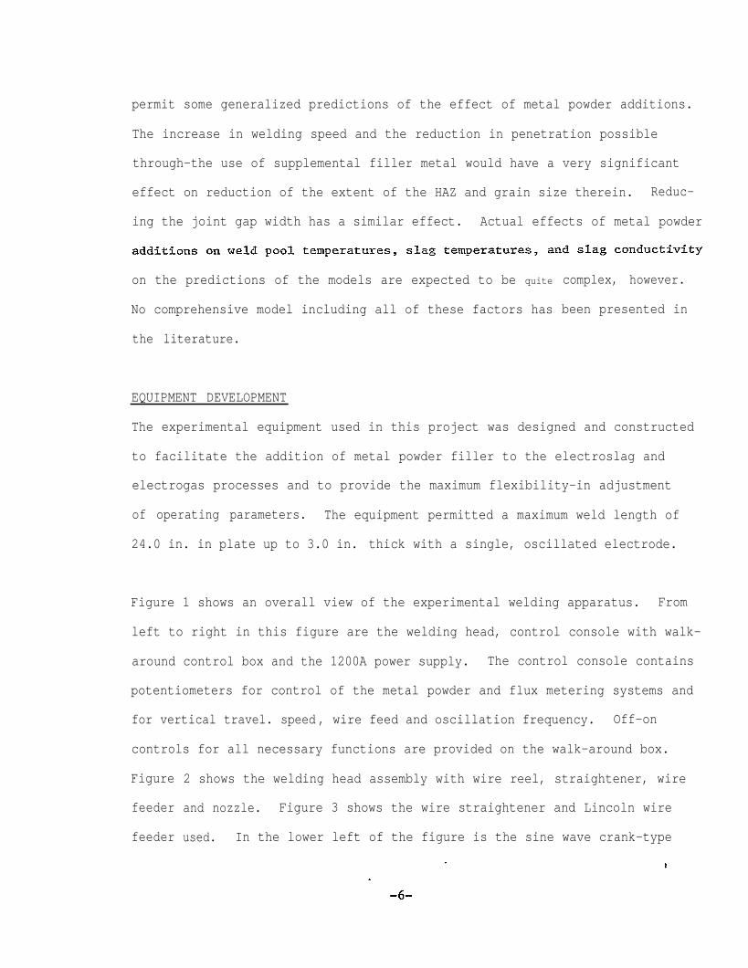
permit some generalized predictions of the effect of metal powder additions.
The increase in welding speed and the reduction in penetration possible
through-the use of supplemental filler metal would have a very significant
effect on reduction of the extent of the HAZ and grain size therein. Reduc-
ing the joint gap width has a similar effect. Actual effects of metal powder
on the predictions of the models are expected to be quite
No comprehensive model including all of these factors has
the literature.
complex, however.
been presented in
EQUIPMENT DEVELOPMENT
The experimental equipment used in this project was designed and constructed
to facilitate the addition of metal powder filler to the electroslag and
electrogas processes and to provide the maximum flexibility-in adjustment
of operating parameters. The equipment permitted a maximum weld length of
24.0 in. in plate up to 3.0 in. thick with a single, oscillated electrode.
Figure 1 shows an overall view of the experimental welding apparatus. From
left to right in this figure are the welding head, control console with walk-
around control box and the 1200A power supply. The control console contains
potentiometers for control of the metal powder and flux metering systems and
for vertical travel. speed , wire feed and oscillation frequency. Off-on
controls for all necessary functions are provided on the walk-around box.
Figure
feeder
feeder
2 shows the welding head assembly with wire reel, straightener, wire
and nozzle. Figure 3 shows the wire straightener and Lincoln wire
used. In the lower left of the figure is the sine wave crank-type

oscillator which drives the entire welding head on its slide. The welding
head detaches from the vertical slide immediately behind the wire feed motor
permitting attachment to a tractor or crawler.
A front view of the welding head with metal powder and flux dispensing tubes
in place is shown in Figure 4. Metal powder is dispensed below the contact
tip and flux dispensed above the nozzle, although, in principle, they can
be dispensed together below the contact tip. This view shows the original
metal dispensing tube which was later replaced with a ceramic nozzle. The
front of the metal powder and flux metering devices are also shown. Figure 5
shows the Tapco metal powder and flux metering devices. The metal powder
metering device is equipped with a shielding gas line so that shielding gas
(Ar-25% C02) may be used to assist in conveying the metal powder to the
electrode during welding.
Figure 6 shows two views of the
copper shoe. The length of the
this traveling shoe is held in
pneumatically activated, moving water-cooled
travelling shoe is 4.5 in. During welding,
place against the plate surface by 25 p.s.i.
air pressure. A water interlock is provided so that loss of water pressure
during welding disengages the power supply. The final configuration ceramic
nozzle used for dispensing metal powder is also shown in this figure. Prior
to each welding test, the nozzle was coated with an
pattern of metal powder dispensing from the ceramic
antispatter compound. The
nozzle with a shielding
gas flow of 12 cfh. is
approximately 0.5-0.75
welding, the powder is
shown in Figure 7. The powder contacts the electrode
in. below the contact tip during welding. During
held in place where it contacts the electrode rather
-7-

than free falling as shown in the figure.
Figure 8 shows two views of the welding head in position for the start of
welding on the run-on tab. A 17.0 in. stationary water-cooled copper shoe is
used. For some welding tests conducted during this project, the stationary
water-cooled copper shoe was replaced by refractory ceramic tile backing
tape. Midpoint of electroslag welding a 15.0 in. long plate is shown in
Figure 9 while the finish of the plate is shown in Figure 10. Note that no
run-off tabs are used. In no case was any cracking of the bead at the finish
of the weld observed even under the most severe strongback restraint conditions.
A completed electroslag weld before slag removal is shown in Figure 11.
-8-

WELDING TESTS
General Considerations
Two types of metal powder filler were examined at the beginning of the
project. These were Hoeganaes Type 434 iron powder and Hobart Type 525
alloy steel powder. The Hoeganaes 434 is the principal ingredient-in
blended powder compositions commonly used for submerged arc welding. This
powder has a somewhat lower packing density than the Hobart 525 powder. As
a consequence, the Hoeganaes 434 powder does not “pack” as well on the
electrode when held in place by electromagnetic forces and is more easily
stripped from the surface of the electrode by the molten slag when operating
in the electroslag mode. The more spherical Hobart 525 powder was found
to pack more densely on the electrode as is therefore better conveyed through
the molten slag and into the weld pool. Also, the lower surface area of the
Hobart 525 powder seems to be an aid to complete powder consumption during
welding and minimization of the tendency for a fraction of the powder to
float on the surface of the slag. For these reasons, all welding tests
described in this report utilized the Hobart 525 powder except where other-
wise noted.
The concept of electromagnetic feeding of metal powder to the weld works
progressively better as welding current is increased, i.e. as the magnetic
field strength around the electrode is increased. At low currents, the
metal powder may be attracted to the walls of the test plate or stripped
from the electrode and remain on the surface of the molten slag. At higher
current
held on
welding
levels, this tendency decreases and a larger fraction of powder is
the surface of the electrode and conveyed through the slag. At
currents typical of the tests performed in this project (ca. 500-700A),
-9-

virtually all the metal powder is bound to the electrode and conveyed into
the weld pool. This is particularly true in the electrogas mode of opera-
tion.
Welding
slag or
welding
voltage is found to be the most significant variable when electro-
electrogas welding with metal powder filler additions. Higher
heat inputs associated with higher voltages also tend to produce a
hotter and more fluid slag which assists in the introduction of metal powder
into the weld pool. Welding with metal powder filler additions therefore
requires an increase in operating voltage, for the reason just cited, to
avoid lack of fusion defects resulting from the cooling effect of the
metal powder. Such welding voltage increases are typically 10-20% over
baseline (no powder) conditions.
Following removal of the slag by chipping and light sandblasting, each
welded test plate was x-rayed and ultrasonically scanned for the presence
of defects in the as-welded condition. Following non-destructive examina-
tion, the plates were subjected to tensile, bend and impact testing (Charpy
V-notch) at a temperate appropriate to the particular
being tested. Impact specimen locations were at weld
in the heat affected zone 3.0 mm from the fusion line
ABS grade of plate
metal centerline,
and in the base metal.
Tests were conducted near the mid-length of the welded plate, i.e. approxi-
mately 8.0 in. from the start of the weld for plates 15.0 in. long. Brinell
hardness was determined directly for weld metal, heat affected zone and base
metal locations on transverse sections. Metallographic
prepared from both longitudinal and transverse sections
specimens were
showing the weld metal
-10-

structure and the full extent of the heat affected
were polished, etched and photographed for record.
zone. These specimens
Hardness traverses
(Rockwell “B”) were made at 2.0 mm intervals from the weld metal centerline
through the heat affected zone and into the base metal. Heat affected zone
widths at the mid-plane of the plate were measured on the transverse sections.
Electroslag Welding Tests (0.50 in. Root Opening)
Table I shows the parameters which were held constant for all welding tests
unless otherwise noted. Tables which follow show welding parameters which
were varied for each of the electrodes tested. In all of these tables,
the parameters presented are those which were found to produce satisfactory
welds with acceptable soundness and the absence of lack of fusion defects,
flux entrapment or incomplete metal powder fusion. Data from welding tests
which did not produce satisfactory results are presented later on in this
report as part of a general discussion of the effect of metal powder filler
additions on process heat
Flux-Cored Electrodes
Hobart Fabco 81
input.
Linde 124 was used as a starting flux to establish
Further additions of flux were not required during
the conductive slag layer.
welding since the flux
content of the electrode was sufficient to maintain the electroslag
operation.
Table II shows welding parameters both with and without metal
powder filler additions on ABS Grade B plate. The deposition
rate for the electrode was increased from 33.75 lbs/hr. with:
no powder addition to as high as 67.5 lbs/hr. at a powder
-11-

to electrode ratio of 1.0. (Metal deposition
are not corrected for flux weight and may be
rates for flux-cored electrodes
assumed to
high.) This increased deposition rate is accompanied by
heat input. The decrease in process heat input is less
from the increased travel speed because voltage must be
powder is added.
crease in process
filler additions.
be approximately 10%
a decrease in process
than that expected
increased when metal
Table II illustrates very dramatically the significant in-
productivity possible through the use of metal powder
The Hobart Fabco 81 electrode was found to be ideal for
purposes of experimentation
in the electroslag mode and
additions.
with the process because of the stable behavior
the absence of the need for continuous flux
Table III shows the mechanical properties of the three test plates prepared
with the Hobart electrode. Tensile strength was acceptable for all three
plates. A significant increase in both weld metal and heat affected zone
impact strength is found through the addition of metal powder filler at a
0.50 ratio. Average weld metal impact strength is increased from 21.0 to
35.8 ft-lbs. , while average heat affected zone impact strength is increased
from 89.3 to 107.7 ft-lbs. Specimens taken from the plate welded at a 0.85
ratio show a decrease in both weld metal and heat affected zone impact
strength although properties are equivalent to those of the plate welded
without metal powder. As Table II shows, however, the increase in produc-
tivity relative to the plate welded without powder is very significant.
It is interesting to note that the heat affected zone impact strengths of
all three electroslag welded plates are significantly higher than the base
metal average of 69.3 ft-lbs. The mechanical property data obtained in these
-12-

tests suggest that the 0.85 ratio may be somewhat above the optimum as far
as mechanical properties
Metallographic specimens
are concerned.
prepared from the three plates are shown in
Figures 12-14. A reduction in
resulting from the addition of
expected from the reduced heat
the extent of the heat affected zone
metal powder filler is apparent. This is
inputs shown in Table II. The photomicrographs
of the three weldments in Figures 12-14 show that the degree
ing within the heat affected zone appears to be less for the
of grain coarsen-
plates welded
with metal powder filler. It may also be noted in these figures that the
amount of penetration of the baseplate, i.e. the actual width of the weld,
decreases with increasing amounts of metal powder filler. Finally, weld
metal grain size, particularly the coarse columnar grains adjacent to the
fusion line, appears to be progressively smaller with the addition of metal
powder filler. Results of the hardness traverses across the transverse
sections are shown in Figure 15. Heat affected zone widths are tabulated
and shown graphically in a later figure in this report. These results will
be presented , in comparison with the other electrodes, in the Discussion
section.
McKay Speedalloy 75
This electrode could not be made to operate in the electroslag mode in
combination with the Linde 124 flux. Excessive amounts of flux addition
were required to keep the arc submerged. The slag was very active with
considerable spatter which plugged the ceramic powder dispensing nozzle.
In the operating range 26-40 V, 300-600 A with metal powder ratios of
0-0.4, no satisfactory welds were obtained. Lack of fusion defects were
-13-

I
sent in each weld.
Hobart PS 588
Table
using
IV shows operating parameters which produced satisfactory weldments
this flux-cored electrode with the Linde 124 flux. As shown in this
table, welds were produced with powder to electrode ratios as high as 1.0
corresponding to a total metal deposition rate of 67.5 lbs/hr. at a process
heat input of 270,000 J/in.
When these tests were repeated after a time interval of approximately three
weeks, satisfactory welds were produced but the
produced a more active slag than was present in
the flux was thoroughly dried before using. On
that moisture pick-up
Airco Supercore
Excellent performance,
Continuous addition of
electrode/flux combination
the first tests even when
this basis, it is possible
Over time may be a problem with this electrode.
similar to the Hobart Fabco 81, was observed.
Linde 124 flux was required during operation,
however, to keep the process fully submerged. Table V shows welding para-
meters found satisfactory for use with metal powder filler additions.
Total metal deposition rates were slightly lower than those obtained with
the Hobart Fabco 81. This electrode was tested at powder to electrode
weight ratios as high as 1.13 which produced some unmelted powder on the
Optimum metal
powder ratio is felt to be in the range 0.5-0.8.
-14-
s
ity
e
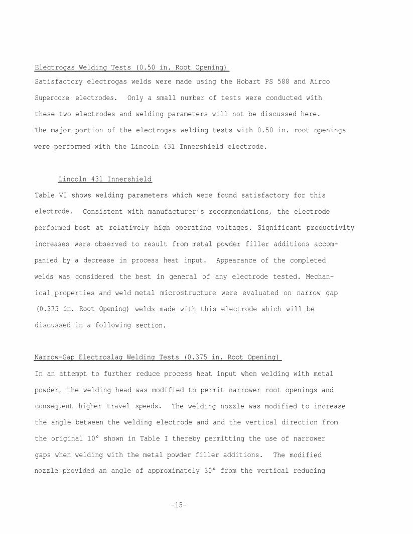
Electrogas Welding Tests (0.50 in. Root Opening)
Satisfactory electrogas welds were made using the Hobart PS 588 and Airco
Supercore electrodes. Only a small number of tests were conducted with
these two electrodes and welding parameters will not be discussed here.
The major portion of the electrogas welding tests with 0.50 in. root opening
were performed with the Lincoln 431 Innershield electrode.
Lincoln 431 Innershield
Table VI shows welding parameters which were found satisfactory for this
electrode. Consistent with manufacturer’s recommendations, the electrode
performed
increases
panied by
welds was
best at relatively high operating voltages. Significant productiv
were observed to result from metal powder filler additions accom-
a decrease in process heat input. Appearance of the completed
considered the
ical properties and weld
(0.375 in. Root Opening)
discussed in a following
best in general of any electrode tested. Mechan-
metal microstructure were evaluated on narrow gap
welds made with this electrode which will be
section.
Narrow-Gap Electroslag Welding Tests (0.375 in. Root Opening)
In an attempt to further reduce process heat input when welding with metal
powder, the welding head was modified to permit narrower root openings and
consequent higher travel speeds. The welding nozzle was modified to increas
the angle between the welding electrode and and the vertical direction from
the original 10° shown in Table I thereby permitting the use of narrower
gaps when welding with the metal powder filler additions. The modified
nozzle provided an angle of approximately 30° from the vertical reducing
-15-
the root opening to
electrode angle was
0.25 in. During operation, it was found that this
too large since very slight variations in the level
of the slag during welding permitted large changes in the horizontal
displacement of the electrode and led to severe arc strikes on the
stationary copper shoe. For this reason, the electrode angle was decreased
to approximately 20° permitting a minimum root gap of 0.375 in. This
configuration proved satisfactory and was retained. The “narrow gap”
welding tests retained all of the operating parameters shown in Table I
with the exception of increasing the electrode angle to 20° and decreasing
the root opening to 0.375 in.
Metal Powder-Cored Electrodes
McKay 215463-ES
This electrode contains a metal powder core which constitutes approximately
40% of the weight of the composite electrode. Table VII shows welding para-
meters found satisfactory for use with this electrode in combination with
Arcos BV flux on Grade AH 36 plate. As shown in this table, welds were
produced with powder to electrode ratios as high as 0.5 corresponding to a
total metal deposition rate of 50.63 lbs/hr. at a process heat input of
315,000 J/in. Welding tests performed at ratios higher than 0.5 were unsuccess-
ful in that the welds were consistently cold, i.e. the additions of flux
during welding resulted in lack of fusion defects at each point where the
flux was added. The high metal powder content of the core itself may produce
significant cooling of the weld pool. Addition of a small amount of metal
powder filler therefore leads very quickly to a “cold weld” situation.
With the McKay 215463-ES/Arcos BV combination, the weld surface was
-16-

consistently “pock-marked” on the side of the stationary water cooled copper
shoe. The “pock-marked" appearance was not observed in any other wire/flux
combination studied and appeared to be independent of any process para-
meters. The pock-marked surface of the weld appeared to have no effect on
weld metal soundness.
The plate welded with wire only showed acceptable soundness in radiographic
and ultrasonic examination while the plate welded at a powder to wire ratio
of 0.5 contained elongated porosity throughout the length of the weld. Mechan-
ical properties measured for the McKay 215463-ES/Arcos BV combination are
shown in Table VIII.
addition was slightly
tensile strengths are
The yield strength of the weld made with metal powder
higher than that made with no powder while the ultimate
identical. Weld metal Brinell hardness was higher
for the weld made with no powder.
Table VIII shows the CVN impact strength at -4°F for these weldments. The
weld metal impact strength is slightly lower for the sample welded with
metal powder additions while the HAZ impact strengths are slightly higher.
Both sets of HAZ impact strengths would be considered unacceptably low.
The base metal impact strength is also quite low. As noted in the non-
destructive examination of these weldments, the weld metal produced with
metal powder filler additions contained a considerable amount of
porosity. The influence of this porosity of the impact strength
problematic.
Figures 16 and 17 show metallographic
elongated
remains
cross-sections of both weldments.
-17-

Weld metal grain size and
cal for both plates. The
degree of HAZ grain coarsening are essentially identi-
porosity in the plate welded with metal powder
additions is apparent in Figure 17. The hardness traverse of each weld is
shown in Figure 18. Weld metal and HAZ hardness were significantly lower
when metal powder was added although the hardness at the fusion line was
increased slightly.
Linde MC 70
This metal powder-cored electrode was tested in combination with Linde 124flux.
at metal powder ratios of 0.47 and 0.85 on Grade AH 36 plate. It was found use-
ful to increase electrode extension by 0.5-1.0 in. beyond that shown in Table I
when welding with this electrode. Other welding parameters which were found
satisfactory for this wire/fluxx combination are shown in Table IX while
the mechanical properties of the resulting,weldments are shown in Table X.
Yield and tensile-strengths were essentially identical for plates welded
with or without metal powder additions. Weld metal impact strength in-
creased with increasing amounts
decreased when metal powder was
plates welded with metal powder
of metal powder while HAZ impact strength
added. HAZ impact strength of the two
additions were slightly higher than base
metal values for the AH 36 plate.
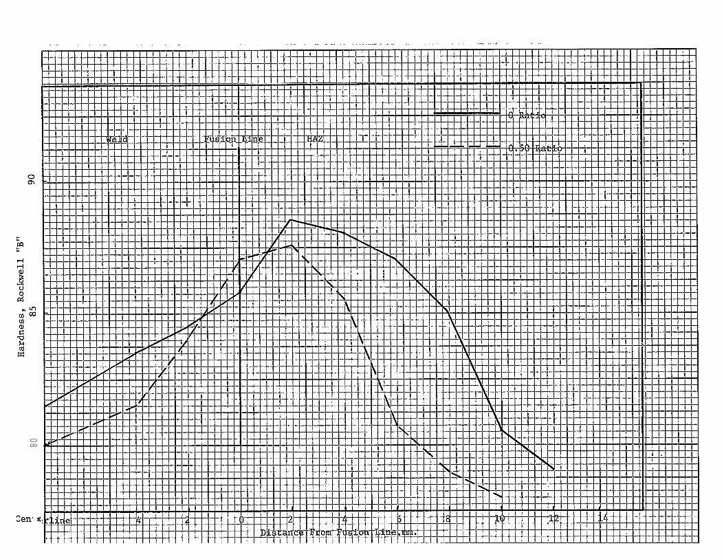
Photomicrographs of the weld metal structures are shown in Figures 19-21
while the results of the hardness traverses are shown in Figure 22. Weld
metal, fusion line and HAZ hardness were all lower when metal powder was
added.
-18-

Solid Electrodes
Linde 29S
This electrode was tested in combination with Linde 124 flux at metal powder
ratios of 0.54 and 0.98 on Grade AH 36 plate. Table XI shows the welding para-
meters found satisfactory for use with this electrode/flux combination. Weld-
ment mechanical properties are shown in Table XII. Yield and tensile
strengths were essentially identical for plates welded with or without
metal powder additions. Weld metal impact strength decreased with the
addition of metal powder at a ratio of 0.54 and increased to the level
of the plate welded without metal powder when.a ratio of 0.98 was used.
The highest HAZ impact strengths were observed for the plate welded with
metal powder at a 0.54 ratio. The low base metal impact strength is also
to be noted.
Figures 23-25 show the metallographic cross sections of the three plates
welded with the Linde 29S electrode and Figure 26 shows the results of the
hardness traverses. The hardness in the weld metal, fusion line and HAZ
was lowest for the plate welded at a ratio of 0.98. Unusual fluctuations
in the hardness curves for the plate welded with no metal powder are seen
in the vicinity of the fusion line.
Narrow-Gap Electrogas Welding Tests (0.375 in Root Opening)
Lincoln 431
Table XIII shows the welding parameters found satisfactory for use with
this electrode on Grade AH 36 plate. Welding tests were
conducted at powder/wire ratios of O and at 0.5 using two
different powders. These two powder types were. Hobart 525
-19-

a special atomized powder, Tapco High
close to that of the Lincoln 431 weld
Al, having a chemistry reasonably
*metal deposit. In Table XIII, weld-
ing process parameters at a ratio of 0.8 are also included.
Welding performance of this electrode was considered exceptionally good.
Finished bead appearance was the best of any electrode, either electroslag
or electrogas, tested in these experiments. All plates welded with the
Lincoln 431 Innershield electrode with and without metal powder filler.
additions showed acceptable soundness in radiographic and ultrasonic examina-
tions.
Table XIV shows weld metal yield and tensile strengths observed for these
plates. Yield and tensile strengths for all three welds are virtually
identical. Significant differences were observed in impact strengths.
Weld metal impact strength at -4°? was considerably lower
welded with metal powder filler additions than that welded
only as are HAZ impact strengths. Comparing the two types
for the plates
with wire
of metal powder
filler additions, inferior properties are obtained with
relative to those obtained with the Hobart 525 with the
the High Al powder
former having impact
strengths at an unacceptably low level.
Figures 27-29 show the microstructure of the electrogas welded plates.
No significant difference in weld metal grain size is observed for the
*High Al Powder Chemistry (Wt.%): Al 0.31, C 0.038, Co 0.01, Cr 0.18, Cu 0.07,Mn 1.21, MO 0.028, Ni 0.07, Si 0.27, V 0.019, Fe Bal.
-20-

three plates. Figure 30 shows the results of the hardness traverses across
the three welds. The plate welded with the Hobart 525 powder at a ratio of
0.5 shows the lowest weld metal, fusion line and HAZ hardness while the
hardness curves for the weld made with no metal powder and with the High Al
powder are very similar.
Airco Metal Core 6
Table XV shows the welding parameters found satisfactory for use with this
electrode with no metal powder and with a ratio of 0.5 on ABS Grade B plate.
In practice, it was found that a slightly rough bead surface was obtained
when shielding gas only was used. This surface roughness could be eliminated
by the addition of very small amounts of flux during welding.
The 0.50 ratio test plate prepared for mechanical property evaluations was found
to contain gross centerline porosity. There is reason to believe that this
porosity was the result of moisture pick-up in the metal powder. This plate
was nonetheless subjected to testing so that impact properties could be
determined. Table XVI shows the results of the mechanical properties tests.
The low tensile strength and elongation of the plate welded with metal powder
are due to the porosity in the weld metal centerline region. Highest weld
metal impact strength was found for the plate welded with metal powder while
the reverse was true for HAZ impact strength.
Figures 31 and 32 show the metallographic cross sections of these welds.
Figure 33 shows the results of the hardness traverses. Weld metal hardness
was higher for
without powder
the plate welded with metal powder while the plate welded
showed the highest HAZ hardness.
-21-
o
Narrow-Gap Electroslag Welding Tests (23.0 in. Long Plate)
In an attempt to determine whether the welding process had stabilized and
could be expected to yield uniform weldment properties over the entire
length of weld, the water-cooled stationary shoe was extended to permit
welding of 23.0 in. long plates. The Hobart Fabco 81 electrode was used with n
flux additions other than Linde 124 as a starting flux. Table XVII shows
the welding parameters used to produce a heat input of 216,000 J/in. at a
metal powder ratio of 0.5. The weld was found to be sound in both radio-
graphic and ultrasonic inspection.
The plate was tested at locations 8.0 and 18.0 in. from the start of the
weld. The results of these tests are shown in Table XVIII. Tensile prop-
erties at the 8.0 and 18.0 in. locations are identical. Impact strengths
are quite similar at the two locations with the 18.0 in. location showing
slightly lower values for both weld metal and HAZ. Preparation of welds
of much greater length , at least several feet, would be necessary to deter-
mine whether the metal powder process has reached steady-state operation
and
The
will. not produce any degradation of weldment mechanical properties.
results of this test suggest that such a degradation is not expected.
Additional Electroslag Welding Tests
Several experiments were conducted using an Airco constant Potential Power
supply for examination of the performance of the experimental apparatus
with a CP supply. These
flux-cored electrode.
tests were conducted using the Hobart Fabco 81
-22-

The
both
with
tests showed the welding behavior of the experimental apparatus
with and without metal powder filler additions to be satisfactory
the CP supply.
Metal Powder-Bearing Fluxes
Linde 39B and Airco (Kobe) metal powder-bearing fluxes were evaluated with
and without metal powder filler additions. Although these fluxes were
not originally devised for electroslag welding, both appear to show consid-
erable
not be
bridge
promise for this type of usage. With both fluxes, the process could
started using the metal powder-bearing flux since they tended to
over rather than fuse and explode. from the weld. For this reason,
Linde 124 was used as a starting flux to initiate the conductive slag layer.
Gradual additions of the metal powder-bearing flux were made during welding
until the slag consisted of 100% metal powder-bearing flux.
Linde 39B
Table XIX shows welding parameters found satisfactory for this flux used
in combination with the Airco Supercore flux-cored electrode both with and
without metal powder filler additions. When adding flux during operation,
the flux is magnetically attracted and adheres to the walls of the base
plates because of the metal powder contained within the flux. This served
to “precoat” the plate walls with flux and was not found to be objection-
able. Satisfactory welds were also produced using the metal powder metering
device to dispense the 39B flux which was weakly bound to the electrode and
carried to the slag pool during welding.
-23-

This flux was found to be voltage sensitive during operation. At high opera-
ting voltages (38-40V),
the unmelted flux which
ting voltages (28-34V),
was quite satisfactory.
and-no tendency for weld
istics were acceptable.
there was a strong tendency for stray arcing through
adhered to the walls
the behavior,of this
Weld appearance and
of the plates. At lower opera-
flux in electroslag operation
soundness
metal cracking was observed.
were
Flux
satisfactory
peeling character-
Airco (Kobe) Flux.
Electroslag welding with this flux was somewhat more erratic than with
Linde 39B. Table XX shows welding conditions found satisfactory with and
without metal powder filler additions. The high voltage required for
complete. consumption of metal powder filler additions tended to make the
process unstable with an arc pulsating in and out of the molten slag layer.
The flux is stable at lower voltages in electroslag welding but quite
sensitive to changes in operating variables. The same tendency for flux
adherence to the walls of the test plate and arcing through the bound
flux at high voltages was also noted. Peeling characteristics of the flux
were very good but the shape of the finished bead tended to be somewhat
irregular at all operating voltages.
Electroslag and Electrogas Welding With Ceramic Backing Tape
Two types of ceramic tile backing tape produced by 3M were evaluated for the
purpose of replacing the stationary copper shoe. It was felt that the re-
duced
metal
heat input possible with electromagnetic feeding of
powder would permit the use of the ceramic backing.
high ratios of
(It is acknowledged
-24-

the 0.5 in. root opening used
success would be significantly
The 4.5 in. moving shoe used for
a 6.0 in. moving shoe to provide
electroslag and electrogas welds
was probably too large. The likelihood of
improved by a reduction in the root gap.)
most of the welding tests was replaced by
additional cooling power. Successful
were made at a powder to
of 1.0 and a travel speed of approximately 5.0 ipm: only
electrode ratio
a small percentage
of the welds attempted, however, were successfully completed. The principal
difficulty encountered with the ceramic tile backing tape was in starting
the process. Since only one cooling shoe was used, runouts could occur
before the process could be stabilized and powder addition begun. During
operation, runouts were observed to be due not to any failure of the ceramic
tile but to failure to contain the molten metal between the edge of the tile
and the base plate. This
ciently tight against the
resulted from
base plate.
the ceramic tile not being suffi-
Both the electroslag and electrogas welding with
metal powder filler additions should be feasible
root openings are used. In
meant that occasionally the
width of the ceramic tiles.
ceramic backing tapes and
particularly if narrower
the present work, the 0.50 in. root opening
width of the weld bead became greater than the
DISCUSSION OF RESULTS ON ELECTROSLAG AND ELECTROGAS WELDING TESTS
Since the two major objectives of this program are improved productivity
and improved weldment properties through decreased process heat input, it
is interesting to group all the welding test results in a master plot of
-25-
metal powder versus process heat input. Data for all electroslag and
electrogas electrodes are shown in Figure 34 and, even with the considerable
diversity of electrode types and welding conditions, a surprisingly coherent
picture emerges. In this figure, the filled points represent satisfactory
performance, i.e. sound weld metal, free of lack of fusion defects. The
open points represent insufficient
of fusion defects, unmelted powder
Figure 34 pertains to the 0.50 in.
process heat input which results in lack
in the weld and/or slag entrapment.
root opening/ 25° included angle joint
geometry and 3/32 (.094) in. electrode diameter.
Examination of the figure shows a trend in the data despite the diverse
types of electrodes used. At a metal
electroslag or electrogas welds can be
excess of approximately 325,000 J/in.,
unsatisfactory welds are produced. As
powder ratio of O, satisfactory
produced at process heat inputs in
while at lower process heat inputs
the metal powder
is increased to 0.5, satisfactory welds can be produced
to electrode ratio
at process heat
inputs in excess of approximately 275,000 J/in., while at lower inputs,
unsatisfactory welds are obtained. This means that as metal powder is
added to the weld, the powder is actually being consumed by excess process
heat, i.e. the process is becoming more “efficient” as well as more produc-
tive. With further increases in the metal powder ratio to approximately
0.75, sound welds may
However, as the metal
1.0, the process heat
defects in the weld.
be produced at lower heat inputs of 240,000 J/in.
powder ratio is further increased to the vicinity of
input must be increased to avoid lack of fusion
From the standpoint of efficiency, the optimum ratio
of metal powder to electrode has been exceeded. Productivity continues
to increase as long as a satisfactory weld can be produced.
-26-

An approximate dividing line between sound and unsound weldments when metal
powder ratio is
are produced to
are encountered
Figure 35 shows
plotted against process heat input thus exists. Sound welds
the right of the dividing line and lack of fusion defects
to the left.
the corresponding
root opening, 25° included angle)
data points for the narrow gap (0.375 in.
welding tests. Examination of this figure
shows the same general trend in the data as discussed above. It was orig-
inally expected that the dividing line between sound and unsound weldments
would be shifted to the left for the smaller root opening which was not
observed. This was due to the fact that higher voltage and current settings,
particularly voltage, were found necessary to produce sound welds in the
narrow gap joint configurations. These higher input power settings offset
the heat input reduction due to the-higher travel speeds possible with the
narrow gap. As examples, compare Tables II and XVII for a metal powder
ratio of 0.5 for the Hobart Fabco 81 electrode and Tables VI and XIII at a
ratio of 0.5 for the Lincoln 431 innershield electrode.
The results of the measurements of HAZ widths at the mid-plane of the test
plates are given in Table XXI and shown graphically in Figure 36 for electro-
slag welds. This data shows quite dramatically the decreased process heat
input possible with metal powder additions to the electroslag welding process.
HAZ widths for the electrogas weldments are given in Table XXII and shown
graphically
afforded by
each of the
in Figure 37. These data confirm the lower process heat inputs
metal powder additions to the electrogas process. As shown in
welding procedures developed in this project, this reduced process
-27-
heat input is accompanied by an increase in overall process productivity,
as measured in total pounds per hour of deposited metal, which is directly
proportional to the amount of metal powder added.
The studies of Smirnov et al (8) showed that the degree of weldment property
improvement varied
filler was added.
which are somewhat
degree of property
markedly with the grade of steel tested when metal powder
In testing plain carbon and quenched and tempered grades
similar to ABS Grade B and AH 36, it was found that the
improvement was significantly greater in the plain carbon
grade. This was true for both weld metal and HAZ impact properties. In the
present investigation, significant differences in the effect of metal powder
additions on weldment properties were observed for Grade B and AH 36 plate.
In Grade B plate, weld metal and HAZ impact properties were generally improved
by the addition of metal powder filler. In Grade AH 36 plate however, some
procedures resulted in increases in either weld metal or HAZ impact strength
while others resulted in a decrease of both. NO general trend is apparent
in the data on Grade AH 36 weldment properties. Further study of the effect
of metal powder additions on the properties of high impact strength ABS grades
is clearly warranted as is a further investigation of methods to improve
weld metal soundness when electroslag and electrogas welds are produced
with metal powder filler additions.
-23-

ACKNOWLEDGEMENTS
The author wishes to express his appreciation to Mr. D.E. Easton and
Mrs. F.M. Reynolds of Materials Sciences Northwest for their assistance in
the experimental portions of this work and the preparation of the final
report.
-29-

References
1.
2.
3.
4.
5.
6.
7.
8.
9.
10.
11.
B.E. Paton, “Electroslag Welding”, Second Edition, American
(Translation), 1962
H.C. Campbell, “Electroslag, Electrogas and
Welding Research Council Bulletin, NO. 154,
Related Welding
September 1970.
Welding Society
Processes”,
A.L. Liby and D.L. Olsen, “Metallurgical Aspects of Electroslag Welding:
A Review”, Quarterly of the Colorado School of Mines, Vol. 69, No.1, pp.41-73, 1974
A.M. Makara and M.G. Belfor,"Present State and Future Prospects of Electroslag
Welding”, Welding Production, NO.11, pp. 50-55, 1967
I.I. Ivochkin and 0.1. Steklov, “Prospects of-Using Filler Metal in Powder
Form in Fusion Welding”, Welding Production, No. 6, pp. 22-27, 1969
I.I. Ivochkin and A.F. Sosedov, “On The Effectiveness of Using Filler Metal
in Powder Form in Electroslag Welding”, Welding Production, No. 11, pp. 33-36 1969
I.I. Ivochkin, et al., “Electroslag Welding With Powdered Filler Metal”,
Welding Production, No. 5, pp. 29-33, 1972
S.A. Smirnov, et al-,"Special Structural Features and Mechanical properties of
Electroslag Welded Joints Made Using Powdered Filler Metal”, Automatic Welding,
No. 9, pp. 45-49, 1973
A.N. Khakimov, et al., “Control of the Structure and Properties of Welded
Joints in Electroslag Welding of Steel 10G2FR Strengthened by Heat Treatment”,
Welding Production, No.1, pp. 39-44, 1974
N.P. Roshchupkin, et al., “principles of the Solidification of Weld Metal in the
Electroslag Welding of Steel With Powdered Filler Metal”, Welding Production,
No. 8, pp. 5-9, 1976
F. Eichorn and P.Hirsch, “Investigations
Electroslag Welded Joints-of 60mm.-Thick
to Improve the Mechanical Properties of
Plates of Low Alloy Steels”, Schweissun
und Schneiden, Vol. 28, No. 31 pp. 86-89, 1976
-30-

12.
13•
14.
15.
16.
17•
F. Eichom, P. Hirsch, W.-G. Burchard and F.-S. Chen, “Investigations Into
The Material Structure of Electroslag Welded Joints Made on 60rmn-Thick Plates
of Low Alloy Steels”, Schweissen und Schneiden, Vol. 2S, No. 6, pp.210-214, 1976
F. Eichorn, P.Hirsch and B.Wubbels, “Effect of Welding Technology and Parent
and Filler Materials on the Strength and Toughness of Electroslag Weldments",
Materialprufung, Vol. 19, NO. 8, pp. 342-347, 1977.
F. Eichorn, P. Hirsch, H.W. Langenbahn and B. Wubbels, DVC-Bericht Bd. 52,
pp. 168-172, 1978
S. Kanazawa, et al., “Improved Toughness of the Weld Fusion Zone by Fine
Titanium Nitride Particles and Development of a Steel for Large Heat Input
Welding”, Journal of the Iron and Steel Institute of Japan Vol. 61, No. 11,
pp. 2589-2603, 1975
R.K. Hopkins, “Production of Composite Materials
AIME Electric Furnace Steel Proceedings, Vol. 6,
R.K. Hopkins, “The Electric Ingot Process”, AIME
by the Electric Fusion Process”,
pp. 75-90, 1948
Electric Furnace Steel
Proceedings, Vol. 6, pp.91-105, 1948
18.R.C. Parsons, “The Arcos Process of Continuous Electroslag Powder Melting (CESPM)”,
International Journal of Powder Metallurgy, Vol. 6, NO. 3, pp. 5-18, 1970
19. J. Levaux, “The Melting of Steel Under Electro-Conductor Slag With the Addition
of Metallic Powders”, Proceedings of the Third International Symp osium on
Electroslag and Other Special Melting Technology, pp. 169-181, 1971
20.R.C. Parsons, “Production of Tool Steels by Electroslag Powder Melting”,
Proceedings of the Third International Symposium on Electroslag and Other
Special Melting Technology, pp. 176-193, 1971
21.J. Levaux, “Continuous Electroslag Powder Melting for the Production of
Large Ingots”, Iron and Steel Engineer, pp. 72-76, March 1972
-31-

22. K. Dorschu, “Production of Special Steel Billets by Continuous E1ectroslag
Powder Melting”, Electroslag Refining (Conference), Sheffield, pp. 145-149, 1973
23.J. Descamps and M. Etienne, “Production of Large Ingots by Continuous
Electroslag Powder Melting”, Electroslag Refining (Conference), Sheffield,
pp. 150-154, 1973
24. U.S. Patent 3,344,839
25.B.R. Mateev and B. Ya. Schvartser, “Introduction of Powdered Metal Particies
Into Metal Deposited by the Electroslag Process”, Automatic Welding, No. 2,
26.
27.
28.
29.
pp. 41-43, 1976
1.1. Ivochkin, “Properties of Welded Joints in VKSI Steel When in Biaxial
Tension”, Welding Production, No. 5, pp. 20-25, 1966
F. Eichom, Private Communication
L.P. Eregin, “Calculating the Penetrationin Electroslag Welding”, Welding
production, No. 7, pp. 39-43, 1970
L.P. Eregin, “Influence” of Electroslag Welding Settings on the Thermal
Cycle in the Heat Affected Zone”, Welding Production, No. 2, pp. 8-11, 1971
-32-


Table I Welding Process Parameters
Common to All Tests for 0.50 Root Opening(Except Where Otherwise Noted)
Root Opening (in.)
Electrode Angle.
Electrode Stickout
Shoe Length, Fixed
(in. )
(in. )
Shoe Length, Moving (in.)
Reinforcement (in.)
Water Flow Rate (gpm)
Electrode Diameter (in.)
Oscillation Frequency (cpm)
Oscillation Amplitude (in.)
Flux Depth (in.)
0.50
10” from Vertical
2.0
17.0
4.50
0.063 (1/16)
0.75
0.094 (3/32)
25.0
0.125
0.625
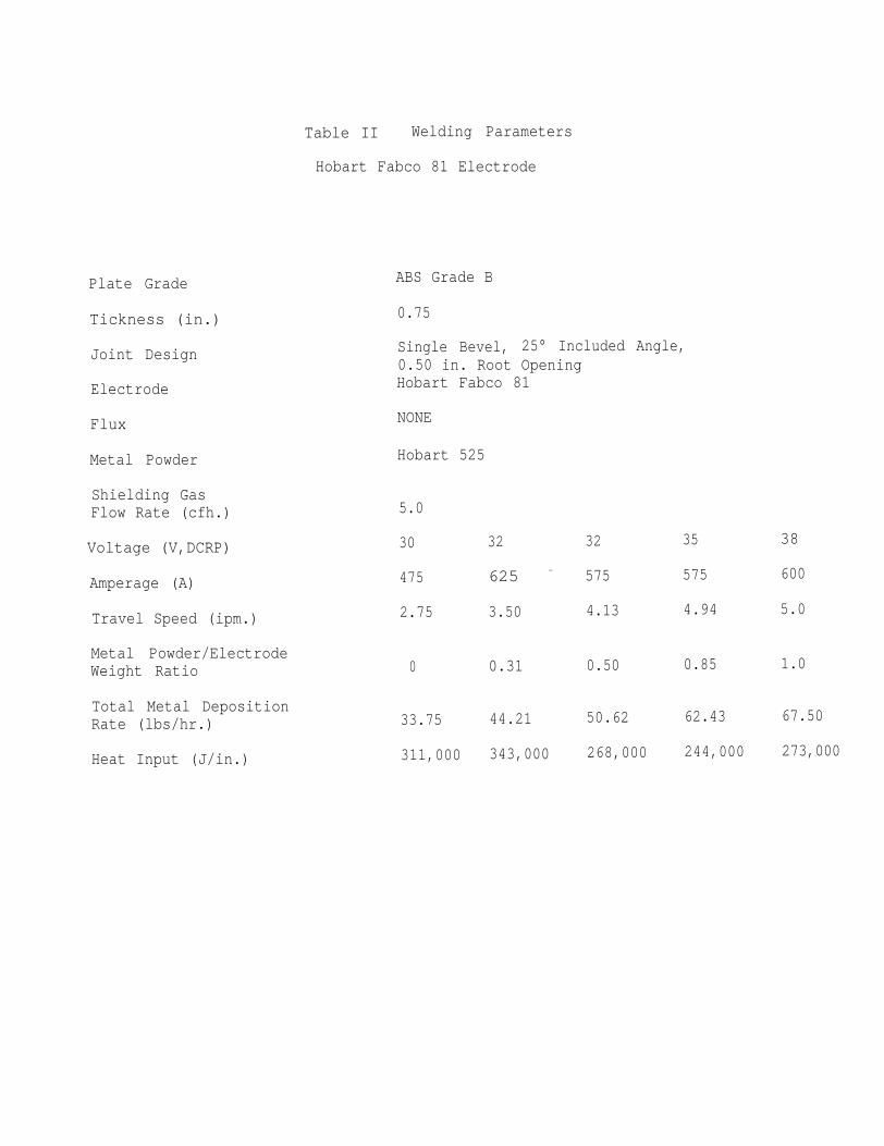
Table II Welding Parameters
Hobart Fabco 81 Electrode
Plate Grade
Tickness (in.)
Joint Design
Electrode
Flux
Metal Powder
Shielding GasFlow Rate (cfh.)
Voltage (V,DCRP)
Amperage (A)
Travel Speed (ipm.)
Metal Powder/ElectrodeWeight Ratio
Total Metal DepositionRate (lbs/hr.)
Heat Input (J/in.)
ABS Grade B
0.75
Single Bevel, 25° Included Angle,0.50 in. Root OpeningHobart Fabco 81
NONE
Hobart 525
5.0
30
475
2.75
0
33.75
311,000
32 32
625 - 575
3.50 4.13
0.31 0.50
44.21 50.62
343,000 268,000
35
575
4.94
0.85
62.43
244,000
38
600
5.0
1.0
67.50
273,000

Table III As-Welded Mechanical Properties
Hobart Fabco 81 Electrode
Yield Strength (psi.)
Tensile Strength
Elongation (%)
Brinell Hardness
(psi.)
(BEN)
Weld MetalHeat Affected ZoneBase Metal
CVN Impact TestTemperature (“F)
O Ratio
52,600*
66,1OO*
33.5*
207
+32
0.5 Ratio
44,700*
68,500*
31. 4*
201.-128
+32
0.85 Ratio
42,900*
62,700*
9.7*
1.82
128
+32
CVN Impact Strength(ft-lbs. )
Weld Metal 20,21,22 Avg.21 31.5,33,43 Avg.35.8Heat Affected Zone 80,94,94 Avg.89.3 100,110,113 Avg.107.7Base Metal - 68,69,71 Avg. 69.3
Transverse Orientation, All Failures in Parent Metal
19,20,31 Avg.23.380,81,83 Avg.81.3
-35-

Table IV Welding Parameters
Hobart PS 588 Electrode
I
Plate Grade
Thickness (in.)
ABS Grade B
0;75
Single Bevel, 25° Included Angle,0.50 in. Root OpeningHobart PS 588
Linde 124
Hobart 525
Joint Design
Electrode
Flux
Metal Powder
Shielding GasFlow Rate (cfh.) 5.0
32
500
3.0
0.25
28.1O
320,000
40
600
5.3
40 40
. 600 - 600
4.0 4.9
Voltage (V,DCRP)
Amperage (A)
Travel Speed (ipm.)
Metal Powder/ElectrodeWeight Ratio
1 . 00.50 0.83
Total Metal DepositionRate (lbs/hr.)
67.50
272,000
50.62 61.80
360,000 294,000Heat Input (J/in.)
-36-
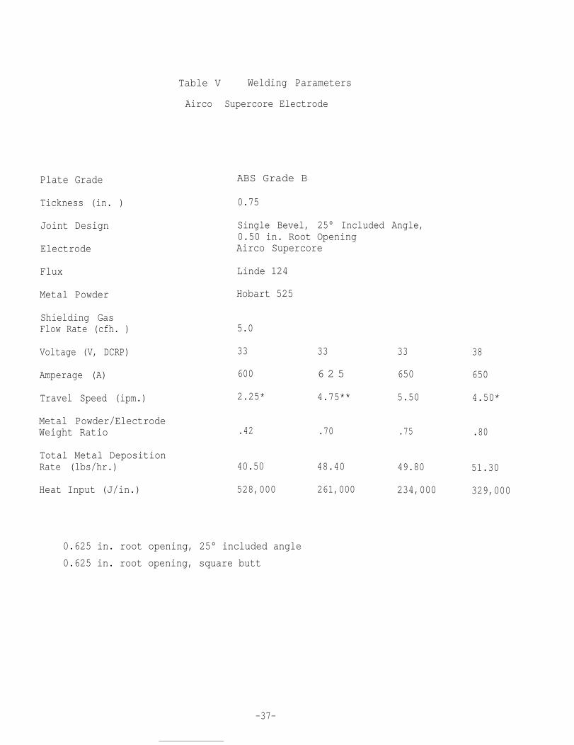
Plate Grade
Tickness (in. )
Joint Design
Electrode
Flux
Metal Powder
Shielding GasFlow Rate (cfh. )
Voltage (V, DCRP)
Amperage (A)
Travel Speed (ipm.)
Table V Welding Parameters
Airco Supercore Electrode
Metal Powder/ElectrodeWeight Ratio
Total Metal DepositionRate (lbs/hr.)
Heat Input (J/in.)
ABS Grade B
0.75
Single Bevel, 25° Included Angle,0.50 in. Root OpeningAirco Supercore
Linde 124
Hobart 525
5.0
33
600
2.25*
.42
40.50
528,000
0.625 in. root opening, 25° included angle
0.625 in. root opening, square butt
33 33
6 2 5 650
4.75** 5.50
.70 .75
48.40 49.80
261,000 234,000
38
650
4.50*
.80
51.30
329,000
-37-

Table VI Welding Parameters
Lincoln 431 Innershield Electrode
Plate Grade
Thickness (in.)
Joint Design
Electrode
Flux
Metal Powder
Shielding GasFlow Rate (cfh.)
Voltage (V,DCRP)
Amperage (A)
Travel Speed (ipm.)
Metal Powder/ElectrodeWeight Ratio
Total Metal DepositionRate (lbs/hr.)
Heat Input (J/in.)
ABS Grade B
0:75
Single Bevel,0.50 in. RootLincoln 431
NONE
Hobart 525
20.0
33
500
3.0
0
37.50
330,000
25° Included Angle,Opening
37
500
4.25
0.50
56.25
261,000
40
525
4.25
0.50
59.0
296,000
-38-

Plate Grade
Tickness (in.)
Joint Design
Electrode
Flux
Metal Powder
Shielding GasFlow Rate (cfh.)
Voltage (V,DCRP)
Amperage (A)
Travel Speed (ipm.)
Metal Powder/ElectrodeWeight Ratio
Total Metal DepositionRate (lbs/hr.)
Table VII Welding Parameters
McKay 215463-ES Electrode
ABS Grade AH36
0:75
Single Bevel, 25° Included Angle,0.375 in. Root OpeningMcKay 215463-ES
Arcos BV
Hobart 525
5.0
39 40
475 575
2.68 4.25
0 0.40
33.75 51.75
Heat Input (J/in.) 414,700 324,000
40
525
4.0
0.50
50.63
315,000
-39-
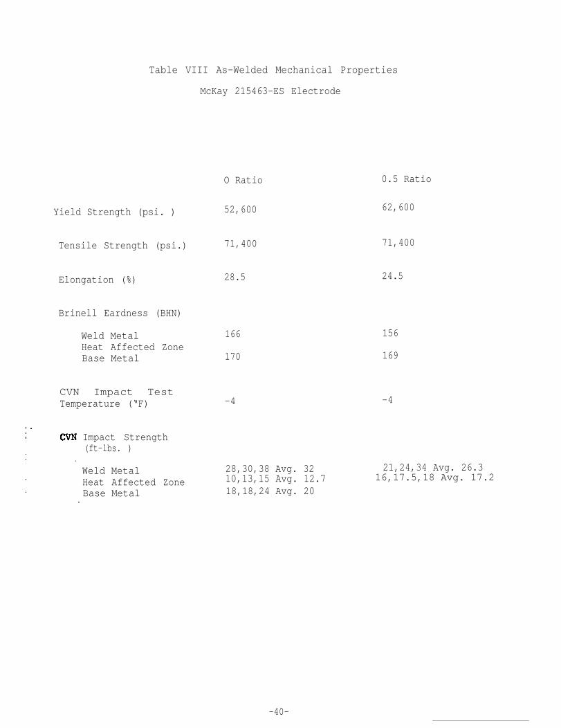
Table VIII As-Welded Mechanical Properties
McKay 215463-ES Electrode
Yield Strength (psi. )
Tensile Strength (psi.)
Elongation (%)
Brinell Eardness (BHN)
Weld MetalHeat Affected Zone Base Metal
CVN Impact Test Temperature (“F)
Impact Strength(ft-lbs. )
Weld MetalHeat Affected ZoneBase Metal
O Ratio
52,600
71,400
28.5
166
170
-4
28,30,38 Avg. 3210,13,15 Avg. 12.718,18,24 Avg. 20
0.5 Ratio
62,600
71,400
24.5
156
169
-4
21,24,34 Avg. 26.316,17.5,18 Avg. 17.2
-40-

Table Ix Welding Parameters
Linde MC 70 Electrode
Plate Grade ABS Grade AH36
0.75Thickness (in. )
Joint Design Single Bevel, 25° Included Angle,0.375 in. Root OpeningLinde MC 70Electrode
Flux Linde 124
Metal Powder Hobart 525
Shielding GasFlow Rate (cfh.) 12.0
Voltage (V,DCIQ) 36
450
36 38
475 475
3.0* 3.75*
Amperage (A)
Travel Speed (ipm.) 3.0
Metal Powder/ElectrodeWeight Ratio o 0 . 4 7 0.85
Total Metal DepositionRate (lbs/hr.) 22.50 33.0 41.63
3 4 2 , 0 0 0 288,800324,000Heat Input (J/in.)
0.50 in. Root Opening
-41-

Table X As-Welded Mechanical
Electrode
Properties
Linde MC 70
0.47
Yield Strength (psi. )
O Ratio Ratio 0.86 Ratio
57,50057,300 57,100
77,700
23.3
Tensile Strength (psi.)
(BHN)
79,40078,100
24.023.6Elongation (%)
Brinell Hardness
147 150153147
1651761 5 3
176Heat Affected ZoneBase Metal 132
-4Impact Test
-4 -4Temperature (“F)
CVN Impact Strength(ft-lbs.)
25,38,42 Avg.34.314,14,23 Avg.17.O
14,18,26 Avg.19.3 8,40,40 Avg. 29.336,40,50 Avg.42.O 12,15,16 Avg.14.312,12,12 Avg.12.O
Weld MetalHeat Affected ZoneBase Metal
-42-

Table XI Welding Parameters
Linde 29S Electrode
Plate Grade ABS Grade AH36
Thickness (in. ) 0:75
Joint Design Single Bevel, 25° Included Angle,0.375 in. Root Opening
Electrode Linde 29S
Flux Linde 124
Metal Powder Hobart 525
Shielding GasFlow Rate (cfh.) 12.0
Voltage (V,DCRP) 36 36 38
Amperage (A) 500 625* 550*
Travel Speed (ipm.) 2.0 4.0 4.0
Metal Powder/ElectrodeWeight Ratio o 0.54 0.98
Total Metal DepositionRate (lbs/hr.) 25.50 39.27 50.49
Heat Input (J/in.) 540,000 337,500 313,500
2.50-3.00 in. Electrode Extension
-43-

Table XII As-Welded Mechanical Properties
Yield Strength (psi. )
Tensile Strength
Elongation (%)
Brinell Hardness
Weld Metal
(psi. )
(BHN)
Heat Affected ZoneBase Metal
CVN Impact Test Temperature (°F)
CVN Impact Strength(ft-lbs )
Linde 29S Electrode
Ratio 0.54 Ratio 0.98 Ratio
5 4 , 4 0 0 53,900 54,900
76,100 76,100 74,600
21.3 21.5 19.2
153 156 153176 170 170144 150 141
-4 -4 - 4
Weld Metal 20,39,42 Avg.33.7 25,25,27 Avg.25.7” 28,36,40 Avg.34.7
Heat Affected Zone 13,14,25 Avg.17.3 30,36,48 Avg.38 2,3,24 Avg.9.7
Base Metal 12,12,12 Avg.12.O
44

Plate Grade
Thickness (in.)
Joint Design
Electrode
Flux
Metal Powder
Shielding GasFlow Rate (cfh.)
Voltage (V,DCRP)
. Amperage (A)
Travel Speed (ipm.)
Metal Powder/ElectrodeWeight Ratio
Total Metal DepositionRate (lbs/hr.)
Heat Input (J/in.)
Table XIII Welding Parameters
Lincoln 431 Innershield
Hobart 525 Powder
ABS Grade AH36
0.75
Single Bevel, 25° Included Angle,0.375 in. Root OpeningLincoln 431 Innershield
NONE
Hobart 525 or Tapco High Al.
25.0
3 . 6 4 0 40 42
525 575 575 600
2.75 4.0 4.5 5.0
0 .50* .50**
33.75 50.62 50.62 60.75
412,400 345,000 306,000 302,000
Tapco High Al. Powder
-45-
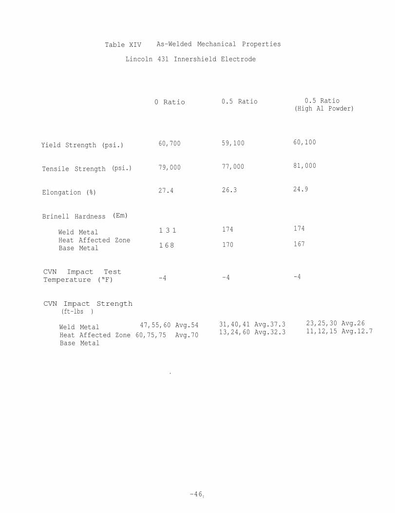
Table XIV As-Welded Mechanical Properties
Lincoln 431 Innershield Electrode
Yield Strength (psi.)
Tensile Strength
Elongation (%)
Brinell Hardness
Weld Metal
(psi.)
(Em)
Heat Affected ZoneBase Metal
CVN Impact Test Temperature (“F)
CVN Impact Strength(ft-lbs )
0 Ratio
60,700
79,000
27.4
1 3 1
168
-4
Weld Metal 47,55,60 Avg.54Heat Affected Zone 60,75,75 Avg.70Base Metal
.
0.5 Ratio 0.5 Ratio
59,100
77,000
26.3
174
170
-4
(High Al Powder)
60,100
81,000
24.9
174
167
-4
31,40,41 Avg.37.3 23,25,30 Avg.2613,24,60 Avg.32.3 11,12,15 Avg.12.7
-46T

Table XV Welding Parameters
Airco Metal Core 6 Electrode
Plate Grade
Thickness (in.)
Joint Design
Electrode
Flux
Metal Powder
Shielding GasFlow Rate (cfh.)
Voltage (V,DCRP)
Amperage (A)
Travel Speed (ipm.)
Metal Powder/ElectrodeWeight Ratio
Total Metal DepositionRate (lbs/hr.)
Heat Input (J/in.)
ABS Grade B
0:75
Single Bevel, 25° Included Angle,0.375 in. Root OpeningAirco 6
NONE (see text)
Hobart 525
35.0
36
450
2.0
0
17.60
486,000
38
525
3.0
0.50
26.40
399,000
-47-

Table XVI As-welded Mechanical Properties
Airco Metal Core 6 Electrode
0.50 Ratioo Ratio
48,900Yield Strength (psi.) 49,900
57,20073,600Tensile Strength (psi.)
4.718.3Elongation (%)
Brinell Hardness (BHN)
“ Weld Metal 1 6 5 Heat Affected Zone 156B a s e M e t a l 134
190 147 132
CVN Impact TestTemperature (°F) +32 +32
CVN Impact Strength
20,26,40 Avg. 28.7
(ft-lbs . )
14,15,20 Avg.16.317,23,37 Avg. 25.718,18,20 Avg. 18.7
MetalAffected ZoneMetal
WeldHeatBase
14,24,24 Avg20.7
-48-

Plate Grade
Thickness (in. )
Joint Design
Electrode
Flux
Metal Powder
Shielding GasFlow Rate (cfh.)
Voltage (V,DCRP)
Amperage (A)
Travel Speed (ipm.)
Metal Powder/ElectrodeWeight Ratio
Total Metal DepositionRate (lbs/hr.)
Heat Input (J/in.)
Table XVII Welding Parameters
Hobart Fabco 81 Electrode23.0 in. Plate Length
ABS Grade B
0.75
Single Bevel, 25° Included Angle,0.375 in. Root OpeningHobart Fabco 81
NONE
Hobart 525
12.5
34
575
4.5
0.50
50.63
261,000
-49-

Table XVIII As-Welded Mechanical Properties
Hobart Fabco 81 Electrode, 23.0 in. Plate
“ 18.0 in Location8.0 in. Location
65,500Yield Strength (psi.) 63,900
85,600 86,400Tensile Strength (psi.)
27 28Elongation (%)
Brinell Hardness (BHN)
Weld MetalHeat Affected Zone“Base Metal
CVN Impact Test “Temperature (“F) +32 . + 3 2
CVN Impact Strength(ft-lbs . )
36,34,36 Avg.35.3 “30.5,29.5,31 Avg.30.3.42.5,23.5,28.5 Avg.31.5 33.5,25.5,32.5 Avg.30.527,27,24.5 Avg.26.2
Weld MetalHeat Affected ZoneBase Metal

Plate Grade
Thickness (in.)
Joint Design
Electrode
Flux
Metal Powder
Shielding GasFlow Rate (cfh.)
voltage (V,DCRP)
Amperage (A)
Travel Speed (ipm.)
Metal Powder/ElectrodeWeight Ratio
Table XIX Welding Parameters
Airco (Kobe) Metal Powder-Bearing Flux
ABS Grade B
Total Metal DepositionRate (lbs/hr.)
Heat Input (J/in.)
0.75
Single Bevel. 25° Included Angle,0.50 in.. Root OpeningAirco Supercore
Airco (Linde 124 Starting)
Hobart 525
5.0
3.3
450
2.50
0
27.0
356,000
33
500
4.0
0.625
48.75
248;000
-51-

Plate Grade
Thickness (in.)
Joint Design
Electrode
Flux
Metal Powder
Shielding GasFlow Rate (cfh.)
Voltage (V,DCRP)
Table XX Welding Parameters
Linde 39B Metal Powder-Bearing Flux
Amperage (A)
Travel Speed (ipm.)
Metal Powder/ElectrodeWeight Ratio
Total Metal DepositionRate (lbs/hr.)
Heat Input (J/in.)
ABS Grade B
0.75
Single Bevel, 25° Included Angle,0.50 in. Root OpeningAirco Supercore
Linde 39B (Linde 124 Starting)
Hobart 525
5.0
33
450
2.5
27.0
356,000
38
500
2.5*
0.50
40.5
456;000
0.625 in. Root Opening
-52-

Table XXI Heat Affected Zone Width at Midplane of Plate
Electroslag Weldments
Electrode
Hobart Fabco 81
McKay 215463 ES
Linde 29S
Metal Powder Ratio
0.00.500.85
0.00.50
0.00.540.98
Linde MC 70 0.00.470.86
HAZ Width (in.)
0.4530.5120.394
0.4530.354
0.5120.4130.295
0.3940.3740.374
-53-

Table XXII Heat Affected Zone Width at Midplane of Plate
Electrogas Weldments
Electrode Metal Powder Ratio
0.00.500.50
(High A1 Powder)
HAZ Width (in.)
o. 4130.2760.315
Airco 6 0.00.50
0.4530.394
-54-

FIGURES

Figure 1. Overall View, Welding Head, Control Console With Walk-AroundBox and Power Supply.
-55-

Figure . Welding Head.
-56-

Figure 3. Wire Straightener and Feed Rolls. Oscillator Crank at Lower Left.
-57-

Figure 4. Front View of Welding Head Showing Metal Powder and FluxDispensing Tubes.
-58-

Figure 5. Tapco Electronic Metering Devices for Flux (left) and MetalPowder (right). Note Shielding Gas-Line to Metal PowderMetering Device.
-59-

Figure 6. Two Views of Pneumatically-Actuated Moving Water-Cooled Shoe andCeramic Nozzle for Dispensing Metal Powder to Electrode.
-68-

Figure 7. Dispensing Metal Powder With Shielding Gas.
-61-

Figure 8. Two Views of Head in Position for Start of Welding 15.0 in. Plate.
-62-

Figure 9. Mid-Point of Welding 15.0 in. Plate in Electroslag Mode.
-63-

Figure 10. Completion of Welding 15.0 in. Plate.
-64-
.

Figure 11. Completed Weld.
-65-

1
Figure 12. Test Plate Welded With Hobart Fabco 81 Electrode.Metal Powder Ratio 0.0.
-66-

Figure 13. Test Plate Welded With Hobart Fabco 81 Electrode.Metal Powder Ratio 0.50.
-67-

Figure 14. Test Plate Welded With Hobart Fabco 81 Electrode.Metal Powder Ratio 0.85.
-68-

0608
-69
-

Figure 16. Test Plate Welded With McKay 215463 ES Electrode.Metal Powder Ratio 0.0.
-70-

Figure 17. Test Plate Welded With McKay 215463 ES Electrode.Metal Powder Ratio 0.50.
-71-
08w

Figure 19. Test Plate Welded With Linde MC 70 Electrode.Metal Powder Ratio 0.0.

Figure20. Test Plate Welded With Linde MC 70 Electrode.Metal Powder Ratio 0.47.
74-
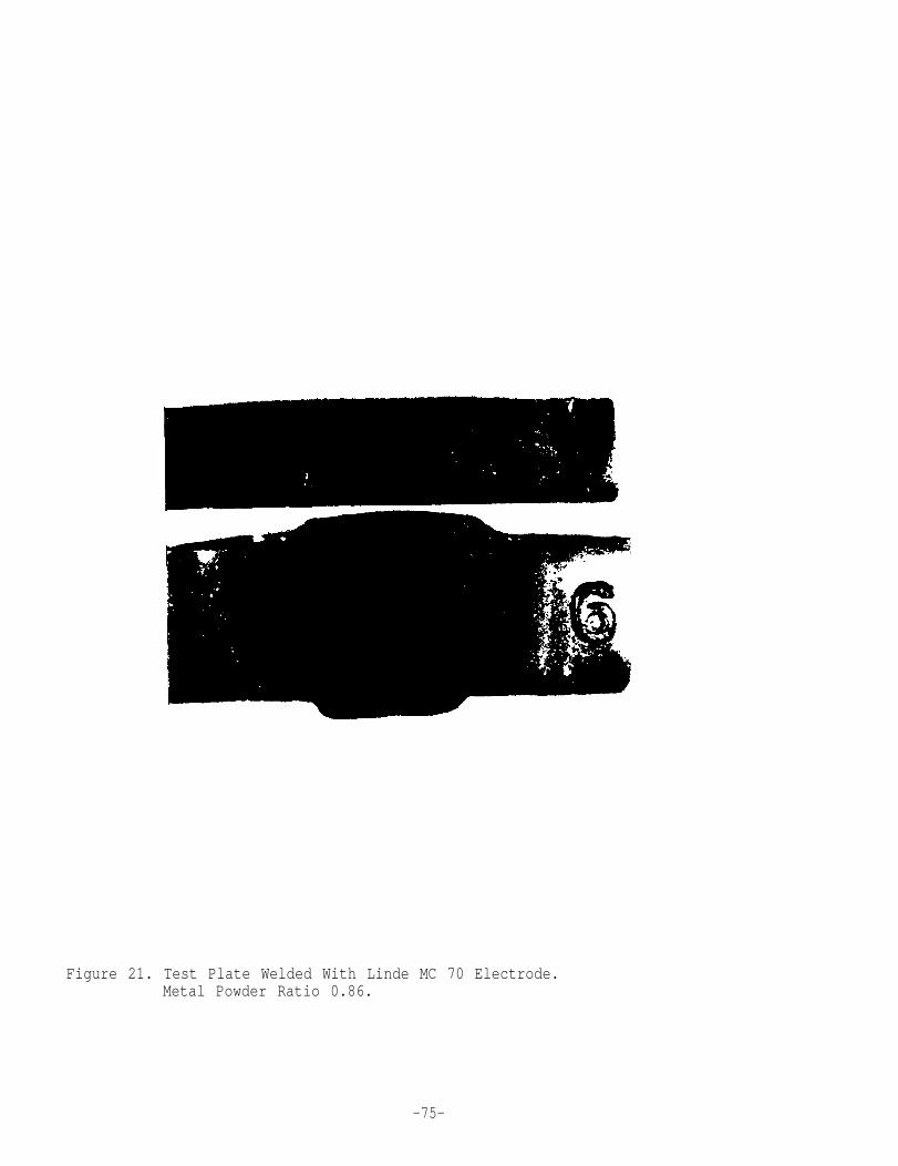
Figure 21. Test Plate Welded With Linde MC 70 Electrode.Metal Powder Ratio 0.86.
-75-


Figure 23. Test Plate Welded With Linde 29S Electrode.Metal Powder Ratio 0.0.
-77-
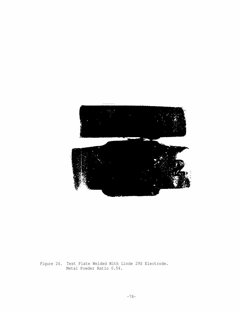
Figure 24. Test Plate Welded With Linde 29S Electrode.Metal Powder Ratio 0.54.
-78-
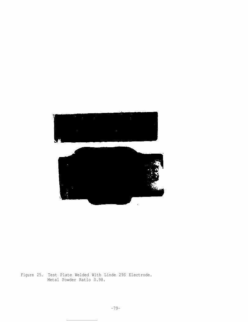
Figure 25. Test Plate Welded With Linde 29S Electrode.Metal Powder Ratio 0.98.
-79-


Figure27. Test Plate Welded With Lincoln 431 Electrode.Metal Powder Ratio 0.0.
-81-

Figure 28. Test Plate Welded With Lincoln 431 Electrode.Metal Powder Ratio 0.50. (Hobart 525 Powder).
-82-

Figure 29. Test Plate Welded With Lincoln 431 Electrode.Metal Powder Ratio 0.50 (High Al Powder).
-83-


.
Figure 31. Test Plate Welded With Airco 6 Electrode.Metal Powder Ratio 0.0.
-85-

Figure 32. Test Plate Welded With Airco 6 Electrode.Metal Powder Ratio 0.50.
-86-


0“1o
-88-

0
-89-