Embed Size (px)
Citation preview

MapInfo Professionalv7.8
Supplement

Information in this document is subject to change without notice and does not represent a commitment on the part of the vendor or its representatives. No part of this document may be reproduced or transmitted in any form or by any means, electronic or mechanical, including photocopying, without the written permission of MapInfo Corporation, One Global View, Troy, New York 12180-8399.© 2004 MapInfo Corporation. All rights reserved. MapInfo, MapInfo Professional, MapBasic, StreetPro and the MapInfo logo are trademarks of MapInfo Corporation and/or its affiliates. MapInfo Corporate Headquarters:Voice: (518) 285-6000Fax: (518) 285-6060Sales Info Hotline: (800) 327-8627Government Sales Hotline: (800) 619-2333Technical Support Hotline: (518) 285-7283Technical Support Fax: (518) 285-6080Contact information for North American offices is located at: http://www.mapinfo.com.Contact information for European and Middle East offices is located at: http://www.mapinfo.co.uk.Contact information for Asia Pacific offices is located at: http://www.mapinfo.com.au.Adobe Acrobat ® is a registered trademark of Adobe Systems Incorporated in the United States.libtiff © 1988-1995 Sam Leffler, copyright © Silicon Graphics, Inc.libgeotiff © 1995 Niles D. Ritter.Portions © 1999 3D Graphics, Inc. All Rights Reserved.HIL - Halo Image Library™ © 1993, Media Cybernetics Inc. Halo Imaging Library is a trademark of Media Cybernetics, Inc.Portions thereof LEAD Technologies, Inc. © 1991-2004. All Rights Reserved.Portions © 1993-2004 Ken Martin, Will Schroeder, Bill Lorensen. All Rights Reserved.Blue Marble © 1993-2004ECW by ER Mapper © 1993-2004VM Grid by Northwood Technologies, Inc., a Marconi Company © 1995-2004™.Portions © 2004 Earth Resource Mapping, Ltd. All Rights Reserved.MrSID, MrSID Decompressor and the MrSID logo are trademarks of LizardTech, Inc. used under license. Portions of this computer program are (c) 1995–1998 LizardTech and/or the university of California or are protected by US patent nos. 5,710,835; 5,130,701; or 5,467,110 and are used under license. All rights reserved. MrSID is protected under US and international patent & copyright treaties and foreign patent applications are pending. Unauthorized use or duplication prohibited.Universal Translator by Safe Software, Inc. © 2004.Crystal Reports ® is proprietary trademark of Crystal Decisions. All Rights Reserved.Products named herein may be trademarks of their respective manufacturers and are hereby recognized. Trademarked names are used editorially, to the benefit of the trademark owner, with no intent to infringe on the trademark.August 2004

Table of Contents
Part I: MapInfo Professional 7.5 Supplement. . . . . . . . . . . . . . . . . . . . . 9
Chapter 1: Upgrading to MapInfo Professional 7.5 . . . . . . . . . . . . . . . . . . . . . . . . . . . . I-10System Requirements for MapInfo Professional . . . . . . . . . . . . . . . . . . . . . . . . . . . . . . . . . . . I-11
Handling Database Connectivity . . . . . . . . . . . . . . . . . . . . . . . . . . . . . . . . . . . . . . . . . . . . . . . I-11Before You Upgrade MapInfo Professional . . . . . . . . . . . . . . . . . . . . . . . . . . . . . . . . . . . . . . . I-11
Navigating the MapInfo Professional 7.5 CD Browser. . . . . . . . . . . . . . . . . . . . . . . . . . . . . . . I-12Upgrading MapInfo Professional. . . . . . . . . . . . . . . . . . . . . . . . . . . . . . . . . . . . . . . . . . . . . . . . I-12
Typical Workstation Installation . . . . . . . . . . . . . . . . . . . . . . . . . . . . . . . . . . . . . . . . . . . . . . . . I-13Custom Workstation Installation . . . . . . . . . . . . . . . . . . . . . . . . . . . . . . . . . . . . . . . . . . . . . . . I-14Network Installation . . . . . . . . . . . . . . . . . . . . . . . . . . . . . . . . . . . . . . . . . . . . . . . . . . . . . . . . . I-15Setting Up Client Workstations . . . . . . . . . . . . . . . . . . . . . . . . . . . . . . . . . . . . . . . . . . . . . . . . I-16
Modifying, Repairing, or Removing MapInfo Pro . . . . . . . . . . . . . . . . . . . . . . . . . . . . . . . . . . I-16Controlling Advanced System Settings . . . . . . . . . . . . . . . . . . . . . . . . . . . . . . . . . . . . . . . . . . I-17Controlling the Location of Application Data Files During Installation . . . . . . . . . . . . . . . . . . . I-18Installing Data . . . . . . . . . . . . . . . . . . . . . . . . . . . . . . . . . . . . . . . . . . . . . . . . . . . . . . . . . . . . . I-20Installing Related Programs, Hardware, and Resources . . . . . . . . . . . . . . . . . . . . . . . . . . . . . I-21Troubleshooting your Installation . . . . . . . . . . . . . . . . . . . . . . . . . . . . . . . . . . . . . . . . . . . . . . . I-23Removing MapInfo Professional from your System. . . . . . . . . . . . . . . . . . . . . . . . . . . . . . . . . I-23
Chapter 2: What’s New in MapInfo Professional 7.5 . . . . . . . . . . . . . . . . . . . . . . . . . . . I-24New Major Features of MapInfo Professional 7.5 . . . . . . . . . . . . . . . . . . . . . . . . . . . . . . . . . . I-25
Accessing Web Map Services . . . . . . . . . . . . . . . . . . . . . . . . . . . . . . . . . . . . . . . . . . . . . . . . . I-25Raster Registration Enhancements . . . . . . . . . . . . . . . . . . . . . . . . . . . . . . . . . . . . . . . . . . . . . I-28Create Points Changes . . . . . . . . . . . . . . . . . . . . . . . . . . . . . . . . . . . . . . . . . . . . . . . . . . . . . . I-31New Shortcuts throughout MapInfo Professional. . . . . . . . . . . . . . . . . . . . . . . . . . . . . . . . . . . I-33Additional OSGB/GML Support . . . . . . . . . . . . . . . . . . . . . . . . . . . . . . . . . . . . . . . . . . . . . . . . I-33Improved Resolution for 3D and Prism Maps . . . . . . . . . . . . . . . . . . . . . . . . . . . . . . . . . . . . . I-35
Printing Enhancements . . . . . . . . . . . . . . . . . . . . . . . . . . . . . . . . . . . . . . . . . . . . . . . . . . . . . . . I-36MapInfo Professional 7.5 Printing Guide . . . . . . . . . . . . . . . . . . . . . . . . . . . . . . . . . . . . . . . . . I-36Additional Fill Patterns . . . . . . . . . . . . . . . . . . . . . . . . . . . . . . . . . . . . . . . . . . . . . . . . . . . . . . . I-36Printing Fill Patterns to Match Screen Display. . . . . . . . . . . . . . . . . . . . . . . . . . . . . . . . . . . . . I-36Setting your Output Setting Preferences . . . . . . . . . . . . . . . . . . . . . . . . . . . . . . . . . . . . . . . . . I-37
Database Enhancements . . . . . . . . . . . . . . . . . . . . . . . . . . . . . . . . . . . . . . . . . . . . . . . . . . . . . . I-39Reading Larger Excel Files into MapInfo Professional . . . . . . . . . . . . . . . . . . . . . . . . . . . . . . I-39Read Oracle Tables in 8.1.7 like 9i . . . . . . . . . . . . . . . . . . . . . . . . . . . . . . . . . . . . . . . . . . . . . I-40
Datum Enhancements . . . . . . . . . . . . . . . . . . . . . . . . . . . . . . . . . . . . . . . . . . . . . . . . . . . . . . . . I-40Enhanced KKJ Projection Algorithm . . . . . . . . . . . . . . . . . . . . . . . . . . . . . . . . . . . . . . . . . . . . I-40
Supplement Table of Contents
Japanese Geodetic Datum Conversion . . . . . . . . . . . . . . . . . . . . . . . . . . . . . . . . . . . . . . . . . . I-40Mapping Enhancements. . . . . . . . . . . . . . . . . . . . . . . . . . . . . . . . . . . . . . . . . . . . . . . . . . . . . . . I-40
Clearing Default Workspace Name After Close All . . . . . . . . . . . . . . . . . . . . . . . . . . . . . . . . . I-40Moving and Offsetting Geographic Objects . . . . . . . . . . . . . . . . . . . . . . . . . . . . . . . . . . . . . . . I-40Increase Memory Size and New Resolution Preference Setting . . . . . . . . . . . . . . . . . . . . . . . I-43Zooming, Panning, and Moving Changes . . . . . . . . . . . . . . . . . . . . . . . . . . . . . . . . . . . . . . . . I-45Zoom Layering Enhancements . . . . . . . . . . . . . . . . . . . . . . . . . . . . . . . . . . . . . . . . . . . . . . . . I-46Snap Enhancements . . . . . . . . . . . . . . . . . . . . . . . . . . . . . . . . . . . . . . . . . . . . . . . . . . . . . . . . I-46Setting and Printing the Map Scale in Layout Windows . . . . . . . . . . . . . . . . . . . . . . . . . . . . . I-47Large Crosshairs . . . . . . . . . . . . . . . . . . . . . . . . . . . . . . . . . . . . . . . . . . . . . . . . . . . . . . . . . . . I-48Custom Symbol Enhancements. . . . . . . . . . . . . . . . . . . . . . . . . . . . . . . . . . . . . . . . . . . . . . . . I-48Improved Object Rotation . . . . . . . . . . . . . . . . . . . . . . . . . . . . . . . . . . . . . . . . . . . . . . . . . . . . I-52Data Disaggregation Dialog Changes . . . . . . . . . . . . . . . . . . . . . . . . . . . . . . . . . . . . . . . . . . . I-53Dot Density Theme Enhancements . . . . . . . . . . . . . . . . . . . . . . . . . . . . . . . . . . . . . . . . . . . . . I-54Object Clean Gaps Modification . . . . . . . . . . . . . . . . . . . . . . . . . . . . . . . . . . . . . . . . . . . . . . . I-54Setting Map Bounds for DBMS Tables . . . . . . . . . . . . . . . . . . . . . . . . . . . . . . . . . . . . . . . . . . I-54Saving a Buffer as a Table. . . . . . . . . . . . . . . . . . . . . . . . . . . . . . . . . . . . . . . . . . . . . . . . . . . . I-56New Voronoi Capabilities. . . . . . . . . . . . . . . . . . . . . . . . . . . . . . . . . . . . . . . . . . . . . . . . . . . . . I-58
Add In Enhancements . . . . . . . . . . . . . . . . . . . . . . . . . . . . . . . . . . . . . . . . . . . . . . . . . . . . . . . . I-61Crystal Reports Changes. . . . . . . . . . . . . . . . . . . . . . . . . . . . . . . . . . . . . . . . . . . . . . . . . . . . . I-61Vertical Mapper Integration . . . . . . . . . . . . . . . . . . . . . . . . . . . . . . . . . . . . . . . . . . . . . . . . . . . I-62
Menu Enhancements . . . . . . . . . . . . . . . . . . . . . . . . . . . . . . . . . . . . . . . . . . . . . . . . . . . . . . . . . I-62Window Menu Changes. . . . . . . . . . . . . . . . . . . . . . . . . . . . . . . . . . . . . . . . . . . . . . . . . . . . . . I-62
Tool Enhancements . . . . . . . . . . . . . . . . . . . . . . . . . . . . . . . . . . . . . . . . . . . . . . . . . . . . . . . . . . I-63New Tools for MapInfo Professional 7.5 . . . . . . . . . . . . . . . . . . . . . . . . . . . . . . . . . . . . . . . . . I-63Enhancements to Existing Tools in MapInfo Professional 7.5 . . . . . . . . . . . . . . . . . . . . . . . . . I-64
EasyLoader Changes . . . . . . . . . . . . . . . . . . . . . . . . . . . . . . . . . . . . . . . . . . . . . . . . . . . . . . . . . I-65MapBasic Enhancements. . . . . . . . . . . . . . . . . . . . . . . . . . . . . . . . . . . . . . . . . . . . . . . . . . . . . . I-65
Appendix A: Directory of MapInfo Professional Shortcuts. . . . . . . . . . . . . . . . . . . . . . I-66Shortcuts for File Menu Items . . . . . . . . . . . . . . . . . . . . . . . . . . . . . . . . . . . . . . . . . . . . . . . . . . I-67Shortcuts for Edit Menu Items . . . . . . . . . . . . . . . . . . . . . . . . . . . . . . . . . . . . . . . . . . . . . . . . . . I-67Shortcut to Tools Menu Items . . . . . . . . . . . . . . . . . . . . . . . . . . . . . . . . . . . . . . . . . . . . . . . . . . I-67Shortcuts to Objects Menu Items . . . . . . . . . . . . . . . . . . . . . . . . . . . . . . . . . . . . . . . . . . . . . . . I-68Shortcuts for Query Menu Items . . . . . . . . . . . . . . . . . . . . . . . . . . . . . . . . . . . . . . . . . . . . . . . . I-68Shortcuts for Options Menu Items . . . . . . . . . . . . . . . . . . . . . . . . . . . . . . . . . . . . . . . . . . . . . . I-68Shortcuts for Map Menu Items. . . . . . . . . . . . . . . . . . . . . . . . . . . . . . . . . . . . . . . . . . . . . . . . . . I-69Shortcut for Layout Menu Item . . . . . . . . . . . . . . . . . . . . . . . . . . . . . . . . . . . . . . . . . . . . . . . . . I-69Shortcuts for Windows Menu Items . . . . . . . . . . . . . . . . . . . . . . . . . . . . . . . . . . . . . . . . . . . . . I-69Shortcuts by Keystroke . . . . . . . . . . . . . . . . . . . . . . . . . . . . . . . . . . . . . . . . . . . . . . . . . . . . . . . I-70
Appendix B: Fill Patterns Used in MapInfo Professional . . . . . . . . . . . . . . . . . . . . . . . I-72Fill Pattern Table . . . . . . . . . . . . . . . . . . . . . . . . . . . . . . . . . . . . . . . . . . . . . . . . . . . . . . . . . . . . . I-73New Fill Patterns (Added in This Release) . . . . . . . . . . . . . . . . . . . . . . . . . . . . . . . . . . . . . . . . I-74
Appendix C: New and Enhanced MapBasic Statements and Functions . . . . . . . . . . . I-78
MapInfo Professional 7.5/7.8
© 2004 MapInfo Corporation. All rights reserved. iv MI_UG.pdf

Supplement Table of Contents
Part II: MapInfo Professional 7.8 Supplement . . . . . . . . . . . . . . . . . . . 95
Chapter 1: Upgrading to MapInfo Professional 7.8 . . . . . . . . . . . . . . . . . . . . . . . . . . . . II-96System Requirements for MapInfo Professional 7.8 . . . . . . . . . . . . . . . . . . . . . . . . . . . . . . . .II-97
Handling Database Connectivity . . . . . . . . . . . . . . . . . . . . . . . . . . . . . . . . . . . . . . . . . . . . . . .II-97Before You Upgrade to MapInfo Professional 7.8 . . . . . . . . . . . . . . . . . . . . . . . . . . . . . . . . . .II-98
Navigating the MapInfo Professional 7.8 CD Browser. . . . . . . . . . . . . . . . . . . . . . . . . . . . . . .II-98Upgrading MapInfo Professional 7.8. . . . . . . . . . . . . . . . . . . . . . . . . . . . . . . . . . . . . . . . . . . . .II-98
Typical Workstation Installation (7.8) . . . . . . . . . . . . . . . . . . . . . . . . . . . . . . . . . . . . . . . . . . . .II-99Custom Workstation Installation (7.8) . . . . . . . . . . . . . . . . . . . . . . . . . . . . . . . . . . . . . . . . . .II-100Network Installation (7.8) . . . . . . . . . . . . . . . . . . . . . . . . . . . . . . . . . . . . . . . . . . . . . . . . . . . .II-102Setting Up Client Workstations (7.8) . . . . . . . . . . . . . . . . . . . . . . . . . . . . . . . . . . . . . . . . . . .II-103
Setting your Database Connection Preferences . . . . . . . . . . . . . . . . . . . . . . . . . . . . . . . . . .II-103Modifying, Repairing, or Removing MapInfo Pro. . . . . . . . . . . . . . . . . . . . . . . . . . . . . . . . . .II-104
Controlling Advanced System Settings (7.8) . . . . . . . . . . . . . . . . . . . . . . . . . . . . . . . . . . . . .II-105Controlling the Location of Application Data Files During Installation (7.8) . . . . . . . . . . . . . .II-106Installing Data . . . . . . . . . . . . . . . . . . . . . . . . . . . . . . . . . . . . . . . . . . . . . . . . . . . . . . . . . . . .II-108Installing Related Programs, Hardware, and Resources (7.8). . . . . . . . . . . . . . . . . . . . . . . .II-109Troubleshooting your Installation . . . . . . . . . . . . . . . . . . . . . . . . . . . . . . . . . . . . . . . . . . . . . .II-111Removing MapInfo Professional 7.8 from your System using Control Panel . . . . . . . . . . . .II-111Removing MapInfo Professional 7.8 from your System using the CD Browser . . . . . . . . . . .II-111
Chapter 2: What’s New in MapInfo Professional 7.8 . . . . . . . . . . . . . . . . . . . . . . . . . . II-112New Major Features of MapInfo Professional 7.8 . . . . . . . . . . . . . . . . . . . . . . . . . . . . . . . . .II-113
Adding WFS Client Support . . . . . . . . . . . . . . . . . . . . . . . . . . . . . . . . . . . . . . . . . . . . . . . . . .II-113Adding GetFeatureInfo Support to Web Map Service . . . . . . . . . . . . . . . . . . . . . . . . . . . . . .II-124Controlling WMS Server Timeout Values . . . . . . . . . . . . . . . . . . . . . . . . . . . . . . . . . . . . .II-125Clearer WMS Error Messages. . . . . . . . . . . . . . . . . . . . . . . . . . . . . . . . . . . . . . . . . . . . . . .II-126Saving Your Workspace as an XML-Based MWS File . . . . . . . . . . . . . . . . . . . . . . . . . . . . .II-127
Raster Enhancements . . . . . . . . . . . . . . . . . . . . . . . . . . . . . . . . . . . . . . . . . . . . . . . . . . . . . . .II-129Mapping Enhancements. . . . . . . . . . . . . . . . . . . . . . . . . . . . . . . . . . . . . . . . . . . . . . . . . . . . . .II-130
Removed: 256 Character Limit in Text Boxes. . . . . . . . . . . . . . . . . . . . . . . . . . . . . . . . . .II-130More Dot Density Choices for Thematic Maps . . . . . . . . . . . . . . . . . . . . . . . . . . . . . . . . .II-130Snap and Thin Settings now Saved in Metadata . . . . . . . . . . . . . . . . . . . . . . . . . . . . . . .II-130New Preference for Visible Snap Area . . . . . . . . . . . . . . . . . . . . . . . . . . . . . . . . . . . . . . . . .II-130Adding User-Defined Custom Symbols . . . . . . . . . . . . . . . . . . . . . . . . . . . . . . . . . . . . . . . . .II-131New High-Resolution Custom Symbols . . . . . . . . . . . . . . . . . . . . . . . . . . . . . . . . . . . . . . . . .II-132Selecting Sample Size for Cartographic Legend Window . . . . . . . . . . . . . . . . . . . . . . . . . . .II-132Changes to the AutoTrace Mode (Toggle Option for Line Following) . . . . . . . . . . . . . .II-134Sample Data Changes Available . . . . . . . . . . . . . . . . . . . . . . . . . . . . . . . . . . . . . . . . . . . . . .II-135
3D Enhancements . . . . . . . . . . . . . . . . . . . . . . . . . . . . . . . . . . . . . . . . . . . . . . . . . . . . . . . . . . .II-135Datum Enhancements . . . . . . . . . . . . . . . . . . . . . . . . . . . . . . . . . . . . . . . . . . . . . . . . . . . . . . .II-135
French RGF93 Coordinate System . . . . . . . . . . . . . . . . . . . . . . . . . . . . . . . . . . . . . . . . . . . .II-135Australian Coordinate System Modifications . . . . . . . . . . . . . . . . . . . . . . . . . . . . . . . . . . . . .II-136Israeli Coordinate System Added . . . . . . . . . . . . . . . . . . . . . . . . . . . . . . . . . . . . . . . . . . . . .II-136Swedish Coordinate System Added . . . . . . . . . . . . . . . . . . . . . . . . . . . . . . . . . . . . . . . . . . .II-136
MapInfo Professional 7.5/7.8
© 2004 MapInfo Corporation. All rights reserved. v MI_UG.pdf
Supplement Table of Contents
New Swedish Coordinate Systems (SWEREF 99) Added. . . . . . . . . . . . . . . . . . . . . . . . . . .II-136Reordered/Added Danish Coordinate Systems . . . . . . . . . . . . . . . . . . . . . . . . . . . . . . . . . . .II-136AirPhotoUSA Conterminous U.S. Coordinate System Now Available . . . . . . . . . . . . . . . . . .II-137
Printing Enhancements . . . . . . . . . . . . . . . . . . . . . . . . . . . . . . . . . . . . . . . . . . . . . . . . . . . . . .II-137New Scale Choices when Printing Maps . . . . . . . . . . . . . . . . . . . . . . . . . . . . . . . . . . . . . .II-137Exporting to CSV Format Available . . . . . . . . . . . . . . . . . . . . . . . . . . . . . . . . . . . . . . . . . .II-138
Database Enhancements . . . . . . . . . . . . . . . . . . . . . . . . . . . . . . . . . . . . . . . . . . . . . . . . . . . . .II-138Default Range Options When Importing MS Excel File . . . . . . . . . . . . . . . . . . . . . . . . . . . . .II-138Controlling Treatment of Imported Excel Tables . . . . . . . . . . . . . . . . . . . . . . . . . . . . . . . . . .II-139
Tool Enhancements . . . . . . . . . . . . . . . . . . . . . . . . . . . . . . . . . . . . . . . . . . . . . . . . . . . . . . . . .II-139Instructions for Adding New Tools to the Tool Manager . . . . . . . . . . . . . . . . . . . . . . . . .II-139Enhanced Split Polyline at Node . . . . . . . . . . . . . . . . . . . . . . . . . . . . . . . . . . . . . . . . . . . . . .II-140Using the Spider Graph Tool . . . . . . . . . . . . . . . . . . . . . . . . . . . . . . . . . . . . . . . . . . . . . . . . .II-141Using the Distance Calculator Tool . . . . . . . . . . . . . . . . . . . . . . . . . . . . . . . . . . . . . . . . . . . .II-142Universal Translator Upgrade Improves Log File Viewing . . . . . . . . . . . . . . . . . . . . . . .II-144Universal Translator Upgrade Includes Finnish and JDG2000 Projections . . . . . . . . . . . . . .II-146New Tool: The Synchronize Windows Utility . . . . . . . . . . . . . . . . . . . . . . . . . . . . . . . . . .II-146COGOLine (Create Line by Length) Utility Improvements. . . . . . . . . . . . . . . . . . . . . . . .II-147Search and Replace Tool Updates Multiple Column Entries. . . . . . . . . . . . . . . . . . . . . .II-149GeoTracker Upgrade Completed . . . . . . . . . . . . . . . . . . . . . . . . . . . . . . . . . . . . . . . . . . . .II-149
Documentation Enhancements . . . . . . . . . . . . . . . . . . . . . . . . . . . . . . . . . . . . . . . . . . . . . . . .II-149Upgraded the Coordinate Systems Section of the User Guide . . . . . . . . . . . . . . . . . . . .II-149Printing Guide 7.8 Updated. . . . . . . . . . . . . . . . . . . . . . . . . . . . . . . . . . . . . . . . . . . . . . . . .II-150Upgraded ProViewer Documentation Available . . . . . . . . . . . . . . . . . . . . . . . . . . . . . . . .II-150Enhanced Line Style Editor Documentation Available . . . . . . . . . . . . . . . . . . . . . . . . . .II-150MapX Mobile Viewer Documentation To Be Available. . . . . . . . . . . . . . . . . . . . . . . . . . . . . .II-150MapInfo Professional Tutorial and Data Available . . . . . . . . . . . . . . . . . . . . . . . . . . . . . . . . .II-150
Licensing Enhancements. . . . . . . . . . . . . . . . . . . . . . . . . . . . . . . . . . . . . . . . . . . . . . . . . . . . .II-150MapBasic Enhancements. . . . . . . . . . . . . . . . . . . . . . . . . . . . . . . . . . . . . . . . . . . . . . . . . . . . .II-151
WFS Support . . . . . . . . . . . . . . . . . . . . . . . . . . . . . . . . . . . . . . . . . . . . . . . . . . . . . . . . . . . . .II-151MGRS Conversion Functions . . . . . . . . . . . . . . . . . . . . . . . . . . . . . . . . . . . . . . . . . . . . . . . .II-151Printing a Window to a File . . . . . . . . . . . . . . . . . . . . . . . . . . . . . . . . . . . . . . . . . . . . . . . . . .II-152Polyline Split at Node. . . . . . . . . . . . . . . . . . . . . . . . . . . . . . . . . . . . . . . . . . . . . . . . . . . . . . .II-152Dot Density for Thematic Maps . . . . . . . . . . . . . . . . . . . . . . . . . . . . . . . . . . . . . . . . . . . . . . .II-152Cartographic Legend Sample Size . . . . . . . . . . . . . . . . . . . . . . . . . . . . . . . . . . . . . . . . . . . .II-153Excel Column Import . . . . . . . . . . . . . . . . . . . . . . . . . . . . . . . . . . . . . . . . . . . . . . . . . . . . . . .II-153Excel CSV Export . . . . . . . . . . . . . . . . . . . . . . . . . . . . . . . . . . . . . . . . . . . . . . . . . . . . . . . . .II-153Running the MapInfo Professional Tutorial . . . . . . . . . . . . . . . . . . . . . . . . . . . . . . . . . . . . . .II-154
Appendix A: Working with Coordinate Systems and Projections . . . . . . . . . . . . . . . II-156Working with Coordinate Systems . . . . . . . . . . . . . . . . . . . . . . . . . . . . . . . . . . . . . . . . . . . . .II-157
Elements of a Coordinate System . . . . . . . . . . . . . . . . . . . . . . . . . . . . . . . . . . . . . . . . . . . . .II-157Understanding Coordinate Systems . . . . . . . . . . . . . . . . . . . . . . . . . . . . . . . . . . . . . . . . . . .II-157
Building Blocks of a Coordinate System . . . . . . . . . . . . . . . . . . . . . . . . . . . . . . . . . . . . . . . .II-162Understanding Coordinate Systems, Projections, and their Parameters. . . . . . . . . . . . . . . .II-162Projection Types . . . . . . . . . . . . . . . . . . . . . . . . . . . . . . . . . . . . . . . . . . . . . . . . . . . . . . . . . .II-163
MapInfo Professional 7.5/7.8
© 2004 MapInfo Corporation. All rights reserved. vi MI_UG.pdf

Supplement Table of Contents
Datums. . . . . . . . . . . . . . . . . . . . . . . . . . . . . . . . . . . . . . . . . . . . . . . . . . . . . . . . . . . . . . . . . .II-166Units. . . . . . . . . . . . . . . . . . . . . . . . . . . . . . . . . . . . . . . . . . . . . . . . . . . . . . . . . . . . . . . . . . . .II-174Coordinate System Origin . . . . . . . . . . . . . . . . . . . . . . . . . . . . . . . . . . . . . . . . . . . . . . . . . . .II-174Standard Parallels (Conic Projections) . . . . . . . . . . . . . . . . . . . . . . . . . . . . . . . . . . . . . . . . .II-175Oblique Azimuth (Hotine Oblique Mercator) . . . . . . . . . . . . . . . . . . . . . . . . . . . . . . . . . . . . .II-175Scale Factor (Transverse Mercator) . . . . . . . . . . . . . . . . . . . . . . . . . . . . . . . . . . . . . . . . . . .II-175False Easting and False Northing . . . . . . . . . . . . . . . . . . . . . . . . . . . . . . . . . . . . . . . . . . . . .II-175Range (Azimuthal Projections) . . . . . . . . . . . . . . . . . . . . . . . . . . . . . . . . . . . . . . . . . . . . . . .II-175About Polyconic Coordinate Systems . . . . . . . . . . . . . . . . . . . . . . . . . . . . . . . . . . . . . . . . . .II-175Examples of Projection Entries in the MAPINFOW.PRJ File . . . . . . . . . . . . . . . . . . . . . . . . .II-176
New Projections in the MAPINFOW.PRJ File . . . . . . . . . . . . . . . . . . . . . . . . . . . . . . . . . . . . .II-178Using the New Projection in a Coordinate System . . . . . . . . . . . . . . . . . . . . . . . . . . . . . . . .II-179Entering a New Coordinate System (Example) . . . . . . . . . . . . . . . . . . . . . . . . . . . . . . . . . . .II-180
Understanding Affine Transformations . . . . . . . . . . . . . . . . . . . . . . . . . . . . . . . . . . . . . . . . .II-181Description of an Affine Transformation. . . . . . . . . . . . . . . . . . . . . . . . . . . . . . . . . . . . . . . . .II-181
Frequently Asked Questions . . . . . . . . . . . . . . . . . . . . . . . . . . . . . . . . . . . . . . . . . . . . . . . . . .II-184For More Information . . . . . . . . . . . . . . . . . . . . . . . . . . . . . . . . . . . . . . . . . . . . . . . . . . . . . . . .II-185
Contact Information . . . . . . . . . . . . . . . . . . . . . . . . . . . . . . . . . . . . . . . . . . . . . . . . . . . . . . . .II-185
Appendix B: High-Resolution Custom Symbols . . . . . . . . . . . . . . . . . . . . . . . . . . . . . II-186New High Resolution Custom Symbols . . . . . . . . . . . . . . . . . . . . . . . . . . . . . . . . . . . . . . . . .II-187Enhanced High Resolution Custom Symbols . . . . . . . . . . . . . . . . . . . . . . . . . . . . . . . . . . . .II-189
Appendix C: New and Enhanced MapBasic Statements and Functions . . . . . . . . . . II-190Appendix GL: Glossary of Terms . . . . . . . . . . . . . . . . . . . . . . . . . . . . . . . . . . . . . . . . . II-200Index. . . . . . . . . . . . . . . . . . . . . . . . . . . . . . . . . . . . . . . . . . . . . . . . . . . . . . . . . . . . . . . . . II-215
MapInfo Professional 7.5/7.8
© 2004 MapInfo Corporation. All rights reserved. vii MI_UG.pdf

Supplement Table of Contents
MapInfo Professional 7.5/7.8
© 2004 MapInfo Corporation. All rights reserved. viii MI_UG.pdf

Part I: MapInfo Professional 7.5 Supplement
This part contains the supplement for the MapInfo Professional 7.5 product. We are including this in this document so that you can have one resource for new features for the post-7.0 MapInfo Professional product.
Topics:
Upgrading to MapInfo Professional 7.5 . . . . . . . . . . . . . . . . . . . . . . . . . . . . . . . . . . . I-10What’s New in MapInfo Professional 7.5 . . . . . . . . . . . . . . . . . . . . . . . . . . . . . . . . . . I-24Directory of MapInfo Professional Shortcuts . . . . . . . . . . . . . . . . . . . . . . . . . . . . . . I-66Fill Patterns Used in MapInfo Professional . . . . . . . . . . . . . . . . . . . . . . . . . . . . . . . . I-72New and Enhanced MapBasic Statements and Functions . . . . . . . . . . . . . . . . . . . . I-78

1
Upgrading to MapInfo Professional 7.5This chapter helps you upgrade to MapInfo Professional® 7.5 and all of the components you require to run the product. In addition, there are instructions for fixing problems that come up as part of the upgrade process.
Sections in this Chapter:
System Requirements for MapInfo Professional. . . . . . . . . . . I-11Before You Upgrade MapInfo Professional . . . . . . . . . . . . . . . I-11Upgrading MapInfo Professional . . . . . . . . . . . . . . . . . . . . . . . I-12Modifying, Repairing, or Removing MapInfo Pro . . . . . . . . . . I-16
MapInfo Professional Supplement Chapter 1: Upgrading to MapInfo Professional 7.5
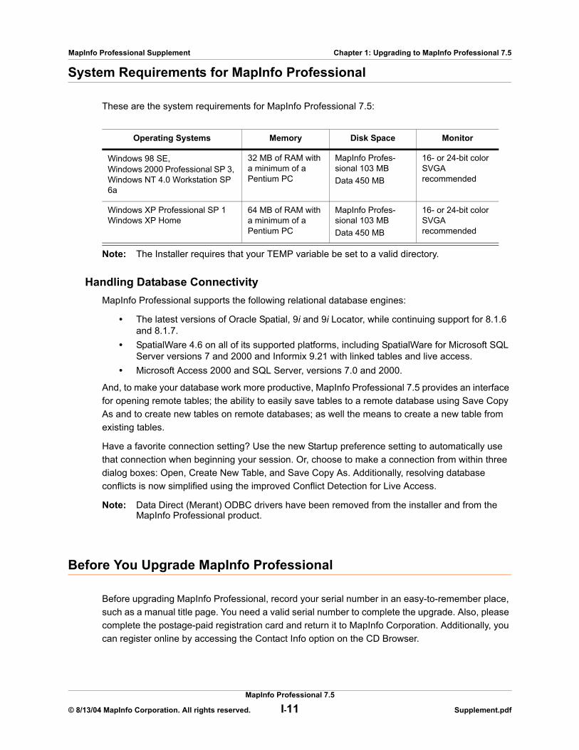
System Requirements for MapInfo Professional
These are the system requirements for MapInfo Professional 7.5:
Note: The Installer requires that your TEMP variable be set to a valid directory.
Handling Database ConnectivityMapInfo Professional supports the following relational database engines:
• The latest versions of Oracle Spatial, 9i and 9i Locator, while continuing support for 8.1.6 and 8.1.7.
• SpatialWare 4.6 on all of its supported platforms, including SpatialWare for Microsoft SQL Server versions 7 and 2000 and Informix 9.21 with linked tables and live access.
• Microsoft Access 2000 and SQL Server, versions 7.0 and 2000.
And, to make your database work more productive, MapInfo Professional 7.5 provides an interface for opening remote tables; the ability to easily save tables to a remote database using Save Copy As and to create new tables on remote databases; as well the means to create a new table from existing tables.
Have a favorite connection setting? Use the new Startup preference setting to automatically use that connection when beginning your session. Or, choose to make a connection from within three dialog boxes: Open, Create New Table, and Save Copy As. Additionally, resolving database conflicts is now simplified using the improved Conflict Detection for Live Access.
Note: Data Direct (Merant) ODBC drivers have been removed from the installer and from the MapInfo Professional product.
Before You Upgrade MapInfo Professional
Before upgrading MapInfo Professional, record your serial number in an easy-to-remember place, such as a manual title page. You need a valid serial number to complete the upgrade. Also, please complete the postage-paid registration card and return it to MapInfo Corporation. Additionally, you can register online by accessing the Contact Info option on the CD Browser.
Operating Systems Memory Disk Space Monitor
Windows 98 SE, Windows 2000 Professional SP 3, Windows NT 4.0 Workstation SP 6a
32 MB of RAM with a minimum of a Pentium PC
MapInfo Profes-sional 103 MBData 450 MB
16- or 24-bit color SVGA recommended
Windows XP Professional SP 1Windows XP Home
64 MB of RAM with a minimum of a Pentium PC
MapInfo Profes-sional 103 MBData 450 MB
16- or 24-bit color SVGA recommended
MapInfo Professional 7.5
© 8/13/04 MapInfo Corporation. All rights reserved. I-11 Supplement.pdf

MapInfo Professional Supplement Chapter 1: Upgrading to MapInfo Professional 7.5
If the MapInfo Professional 7.5 installer detects an existing version of the product, 6.0 or earlier, or detects that the product had been installed at some time, the installer copies the MAPINFOW.WOR, STARTUP.WOR and MAPINFOW.PRF from the operating system's system directory to <user profile root>\Application Data\MapInfo\MapInfo.
Application data (appdata) files are the non-executable data files that MapInfo Professional uses during operation.
Navigating the MapInfo Professional 7.5 CD BrowserThe initial screen of the MapInfo Professional 7.5 CD Browser includes these options:
• Install Products: From this option you can install MapInfo Professional (including DBMS support and translators), free data, access to the documentation, and Install Utilities, including: ECW Compressor, GPS, and Meta Data Browser.
• What’s New: Display a list and description of new and enhanced features.• Online Reference: MapInfo Professional 7.5 provides the following online reference
documents: MapInfo Professional User’s Guide (Unabridged), MapBasic Reference, Crystal Reports User’s Guide, the MapInfo Professional Printing Guide, as well as the Adobe Acrobat Reader.
• Run MapInfo Tutorial: From this option you can run the MapInfo Tutorial to learn more about the basic features of MapInfo Professional.
• Other Products: Display information about MapBasic, MapInfo Discovery, and MapInfo Pro for SQL Server.
Note: To install the remote database connectivity tools, choose the CUSTOM WORKSTATION INSTALLATION option.
Upgrading MapInfo Professional
CAUTION: We strongly recommend that you exit from all Windows programs before beginning the upgrade process.
You must have Administrator rights to run the Installer on NT/2000 and Windows XP.
If your Windows Start menu does not have a MapInfo program folder, the upgrade process creates this folder. If your Windows Start menu already has a MapInfo program folder, the upgrade process creates a new MapInfo icon within that folder.
MapInfo Professional now provides its application data files to each user. Called a Per-User install, this functionality runs the first time you run MapInfo Professional or MapInfo Professional client on a machine, and each time the MapInfo Professional Installer is run thereafter. The application data files include, among others, the Pen Styles file, Custom Symbols files, Graph Support files, and Thematic Legend templates. These files allow different users to have custom settings.
To upgrade MapInfo Professional:
1. On the LAUNCHER menu, click INSTALL PRODUCTS from the MapInfo Professional CD Browser.
MapInfo Professional 7.5
© 8/13/04 MapInfo Corporation. All rights reserved. I-12 Supplement.pdf
MapInfo Professional Supplement Chapter 1: Upgrading to MapInfo Professional 7.5
2. Click MAPINFO PROFESSIONAL. The Install Shield Wizard dialog box displays. Click NEXT to continue the upgrade process and display the License Information dialog box.
3. Click “I ACCEPT THE TERMS” to accept the terms of the license agreement and click NEXT to continue the upgrade. The Customer Information screen displays.
4. Type your name, organization name, and serial number in these required fields. Click NEXT to continue. The Setup Type dialog box displays.
5. Review the following installation types and determine which instructions are appropriate for your upgrade. Click one of the following and click NEXT to continue:• TYPICAL WORKSTATION INSTALLATION. Click this option if you will be using MapInfo
Professional as a desktop application requiring no remote database access or connectivity. See Typical Workstation Installation on page I-13 to continue these upgrade instructions.
• CUSTOM WORKSTATION INSTALLATION. Click this option if you require ODBC or Oracle Spatial connectivity support. See Custom Workstation Installation on page I-14 to continue the upgrade instructions.
• NETWORK INSTALLATION. Click this option if you are upgrading your MapInfo Professional network product. See Network Installation on page I-15 to continue the upgrade instructions. These instructions are for network administrators only. After you upgrade MapInfo Professional on the network, follow the instructions for upgrading MapInfo Professional on client equipment in Setting Up Client Workstations on page I-16.
If you have already upgraded to MapInfo Professional 7.5 or if the product has been previously installed, the Program Maintenance Screen displays. Select MODIFY, REPAIR, or REMOVE to continue. For assistance in completing this process, see Modifying, Repairing, or Removing MapInfo Pro on page I-16. If you find that you need to install ODBC drivers after installing MapInfo Professional, select the MODIFY option to add them.
Typical Workstation InstallationChoose this option to install MapInfo Professional program files, Online Help, Tools, Universal Translator, and Crystal Reports. ArcLink is not selected.
CAUTION: Make sure you have completed the directions in Upgrading MapInfo Professional on page I-12 before beginning these directions.
To continue upgrading a typical workstation:
1. In the Setup Type dialog box, click TYPICAL WORKSTATION INSTALLATION; the Destination Folder screen displays.
Note: If you have an earlier version (or versions) of MapInfo Professional installed and you do not want to overwrite that version, create a new directory name in the next step.
2. Do one of the following:• Click NEXT to accept the destination folder indicated• Click CHANGE to create a new path in the Change Current Destination Folder dialog
box. Type the new path in the Folder name field and click OK to continue. Click NEXT to continue.
The Ready to Install the Program screen displays. Review your selections to ensure that the path is correct before moving on. Click BACK to return to the previous screens to make changes.
MapInfo Professional 7.5
© 8/13/04 MapInfo Corporation. All rights reserved. I-13 Supplement.pdf
MapInfo Professional Supplement Chapter 1: Upgrading to MapInfo Professional 7.5
3. Click INSTALL to begin the upgrade. The Installing MapInfo Professional 7.5 screen displays with a progress bar indicating the status of the upgrade process.
Note: After the upgrade is complete, the prompt: “Would you like to check our web site for any current updates to our product?” displays. If you have an Internet connection, check YES to be connected to the page of the MapInfo Corporation Web site containing information about product updates.
4. When the Installation Complete screen displays, choose FINISH to return to the Install Products screen.
Custom Workstation InstallationChoose this upgrade type to select components and drivers within the MapInfo Professional 7.5 installation program. This is particularly useful if you need to install MapInfo ODBC Connectivity support and Oracle Spatial Object support.
CAUTION: Make sure you have completed the directions in Upgrading MapInfo Professional on page I-12 before beginning these directions.
To continue upgrading using the custom workstation instructions:
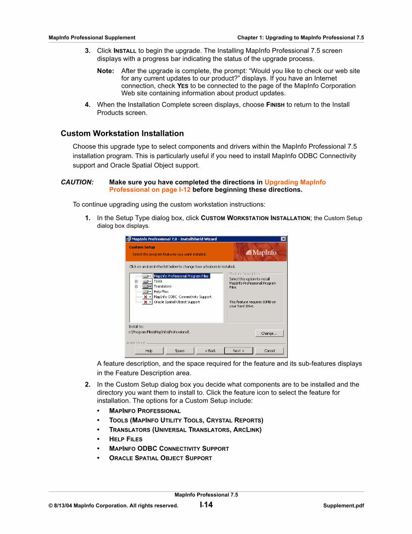
1. In the Setup Type dialog box, click CUSTOM WORKSTATION INSTALLATION; the Custom Setup dialog box displays.
A feature description, and the space required for the feature and its sub-features displays in the Feature Description area.
2. In the Custom Setup dialog box you decide what components are to be installed and the directory you want them to install to. Click the feature icon to select the feature for installation. The options for a Custom Setup include:• MAPINFO PROFESSIONAL
• TOOLS (MAPINFO UTILITY TOOLS, CRYSTAL REPORTS)• TRANSLATORS (UNIVERSAL TRANSLATORS, ARCLINK)• HELP FILES
• MAPINFO ODBC CONNECTIVITY SUPPORT
• ORACLE SPATIAL OBJECT SUPPORT
MapInfo Professional 7.5
© 8/13/04 MapInfo Corporation. All rights reserved. I-14 Supplement.pdf
MapInfo Professional Supplement Chapter 1: Upgrading to MapInfo Professional 7.5
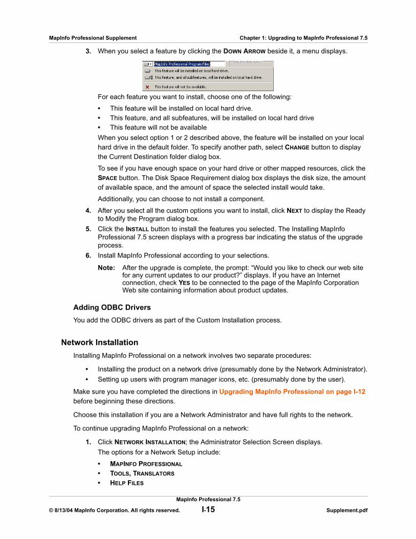
3. When you select a feature by clicking the DOWN ARROW beside it, a menu displays.
For each feature you want to install, choose one of the following:
• This feature will be installed on local hard drive.• This feature, and all subfeatures, will be installed on local hard drive• This feature will not be availableWhen you select option 1 or 2 described above, the feature will be installed on your local hard drive in the default folder. To specify another path, select CHANGE button to display the Current Destination folder dialog box.
To see if you have enough space on your hard drive or other mapped resources, click the SPACE button. The Disk Space Requirement dialog box displays the disk size, the amount of available space, and the amount of space the selected install would take.
Additionally, you can choose to not install a component.
4. After you select all the custom options you want to install, click NEXT to display the Ready to Modify the Program dialog box.
5. Click the INSTALL button to install the features you selected. The Installing MapInfo Professional 7.5 screen displays with a progress bar indicating the status of the upgrade process.
6. Install MapInfo Professional according to your selections.
Note: After the upgrade is complete, the prompt: “Would you like to check our web site for any current updates to our product?” displays. If you have an Internet connection, check YES to be connected to the page of the MapInfo Corporation Web site containing information about product updates.
Adding ODBC DriversYou add the ODBC drivers as part of the Custom Installation process.
Network InstallationInstalling MapInfo Professional on a network involves two separate procedures:
• Installing the product on a network drive (presumably done by the Network Administrator).• Setting up users with program manager icons, etc. (presumably done by the user).
Make sure you have completed the directions in Upgrading MapInfo Professional on page I-12 before beginning these directions.
Choose this installation if you are a Network Administrator and have full rights to the network.
To continue upgrading MapInfo Professional on a network:
1. Click NETWORK INSTALLATION; the Administrator Selection Screen displays.The options for a Network Setup include:
• MAPINFO PROFESSIONAL
• TOOLS, TRANSLATORS
• HELP FILES
MapInfo Professional 7.5
© 8/13/04 MapInfo Corporation. All rights reserved. I-15 Supplement.pdf

MapInfo Professional Supplement Chapter 1: Upgrading to MapInfo Professional 7.5
A feature description, and the space required for the feature, displays in the Feature Description area. Click the option icon to select the option for installation.
2. When you select a feature, a menu displays allowing you to choose to install and/or run the feature and its subfeatures from various locations, including your local hard drive or from CD. If you select the hard drive option, the feature will be installed in the path indicated; on your local hard drive in the folder indicated; to specify a different location, choose Change to display the Current Destination folder screen. If you choose to install an option to your hard drive, the SPACE button is enabled; choose this button to display the Disk Space Requirement dialog box.
Additionally, you can choose to not install a feature. See Installing MapInfo Professional on a Network Drive on page I-16 for additional details.
Note: After the upgrade is complete, the prompt: “Would you like to check our web site for any current updates to our product?” displays. If you have an Internet connection, check YES to be connected to the page of the MapInfo Corporation Web site containing information about product updates.
Installing MapInfo Professional on a Network DriveThe procedure for installing MapInfo Professional on a network drive is the same as the regular installation procedure except for the following:
• Select Network Installation in the Setup Type screen.• Continue as in a Workstation Installation, selecting features, destination locations, etc.
The Network Installation alone does not install any files to the local hard drive.
Setting Up Client WorkstationsTo permit a user to use this network installation of MapInfo Professional, run SETUP.EXE:
1. Map a drive to the MapInfo Professional Install directory.2. Select RUN from the Start menu. 3. Run SETUP.EXE from the [MapInfo install directory]\AddClient. The MapInfo Professional
7.5 Client Welcome screen displays. 4. Click NEXT. The License Information screen displays. 5. Click “I ACCEPT THE TERMS.” Select NEXT. The Customer Information screen displays with
the network install values as the default. 6. Modify for the current instance and select NEXT.7. Click INSTALL to continue the installation.8. Click FINISH to complete the client installation.
Modifying, Repairing, or Removing MapInfo Pro
Use the Program Maintenance feature of the CD Browser to modify, repair, or remove MapInfo Professional 7.0.
To access Program Maintenance:
MapInfo Professional 7.5
© 8/13/04 MapInfo Corporation. All rights reserved. I-16 Supplement.pdf
MapInfo Professional Supplement Chapter 1: Upgrading to MapInfo Professional 7.5
1. Click INSTALL PRODUCTS from the MapInfo Professional CD Browser.2. Click MAPINFO PROFESSIONAL. The Welcome screen displays. Choose NEXT.
The Program Maintenance screen displays.
3. Choose modify, repair, or remove MapInfo Professional 7.5 based on your needs. • Click MODIFY to display the Custom Setup dialog box. See the instructions for Custom
Workstation Installation on page I-14 for more about this process.• Click REPAIR to repair installation errors in the program.• Click REMOVE to remove an existing copy of MapInfo Professional 7.5 from your
system. The installer displays the Remove the Program dialog box. Click REMOVE to uninstall the product’s programs from your system.You can also access the Program Maintenance screen from the Start menu by clicking CONTROL PANEL and then ADD/REMOVE PROGRAMS and finally MAPINFO PROFESSIONAL 7.5.
Controlling Advanced System SettingsMapInfo Professional has some advanced system settings—settings that cannot be configured through a dialog box. These settings allow you to control several low-level, technical aspects of how MapInfo Professional runs. Most MapInfo Professional users do not need to worry about these advanced settings.
For example, MapInfo Professional has a Dynamic Data Exchange (DDE) time-out setting, which controls how long MapInfo Professional tries to communicate with other applications during DDE communications. If you run a MapBasic application, and that application encounters time-out errors during DDE, you may want to increase the DDE time-out setting.
If you need to modify one of MapInfo Professional’s advanced system settings (such as the DDE time-out setting), use the following procedure.
Modifying the Windows RegistryMapInfo Professional stores system settings in the Windows registry. To edit the Windows 98 registry, use the REGEDIT program. To edit the Windows 2000 registry, use the REGEDT32 program.
CAUTION: Be very careful when editing the registry; damaging the registry can cause serious problems in your operating system.
For example, to set MapInfo Professional’s Dynamic Data Exchange (DDE) time-out setting, locate the following key in the registry:
HKEY_LOCAL_MACHINE\SOFTWARE\MapInfo\MapInfo\Common
Within that key, edit the DDeTimeout value. If there is no value by that name, create a new value of type string (this data type is referred to as REG_SZ on Windows NT), and assign the name DDeTimeout to the value. Set the value’s data to be a number, representing the number of milliseconds (e.g., enter 30000 to specify a time-out of 30,000 milliseconds, or 30 seconds).
For more information on editing the registry, see the online help for REGEDIT or REGEDT32.
MapInfo Professional 7.5
© 8/13/04 MapInfo Corporation. All rights reserved. I-17 Supplement.pdf

MapInfo Professional Supplement Chapter 1: Upgrading to MapInfo Professional 7.5
Descriptions of Advanced Registry SettingsThis section describes advanced settings that are stored in the registry.
DDeTimeout = numberThis setting controls MapInfo Professional’s time-out setting in DDE conversations where MapInfo Professional is the client (the application that initiates a conversation). The number represents milliseconds. The default value is 10,000 milliseconds (ten seconds). If you run a MapBasic application that attempts to initiate a DDE conversation, but the conversation fails because the server application does not respond within the time-out period, you may need to increase the DDeTimeout number.
OffscreenBitmap = numberThe number is 0 (zero) or 1 (one). A value of 1 (the default) indicates that MapInfo Professional will process off-screen bitmaps when drawing a map. This means that if you cover a Map window, and then bring the Map window to the front again, the map redraws instantly. If you set this setting to zero, MapInfo Professional will not process off-screen bitmaps. This means that when you bring a Map window to the front, you may have to wait as MapInfo Professional redraws the map.
If you are using a video driver that is uncommon or buggy, and if you encounter video problems with Map windows, you may be able to eliminate those problems by setting the OffscreenBitmap number to 0.
MaxFiles = numberThis setting must be an integer from 10 to 100, indicating how many files MapInfo Professional can open simultaneously. This setting does not limit the number of tables you can open, but it does limit the number of tables you can edit at one time (the number of tables that have unsaved edits). The default value is 29. If you need to work with more files simultaneously, set number to 100.
MaxORACLETILES = numberA value from 0 = unlimited tiles to infinity.
Improving PerformanceTo improve MapInfo Professional’s performance, increase the speed of the processor in the machine. A video accelerator card will increase the speed of the redraw. It will not speed up the initial draw of the map, but all subsequent redraws will be faster. A faster disk cache will also improve performance, as will adding memory.
Controlling the Location of Application Data Files During InstallationBy default, the setup program for MapInfo Professional installs application data files to locations that make sense for the typical user. After installing the product, the user is free to move one or more of the application data files to another predefined location and MapInfo Professional will find that file. For example, the administrator of a machine might move MAPINFOW.PEN from the per user area (its default location) into the install directory so all users on that machine will share the same set of pens.
For IT personnel responsible for a large number of MapInfo Professional installs it is not practical to manually move application data files to realize the desired configuration.
MapInfo Professional 7.5
© 8/13/04 MapInfo Corporation. All rights reserved. I-18 Supplement.pdf
MapInfo Professional Supplement Chapter 1: Upgrading to MapInfo Professional 7.5
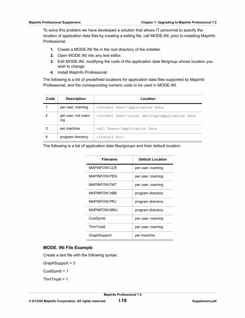
To solve this problem we have developed a solution that allows IT personnel to specify the location of application data files by creating a setting file, call MODE.INI, prior to installing MapInfo Professional.
1. Create a MODE.INI file in the root directory of the installer. 2. Open MODE.INI into any text editor.3. Edit MODE.INI, modifying the code of the application data file/group whose location you
wish to change.4. Install MapInfo Professional.
The following is a list of predefined locations for application data files supported by MapInfo Professional, and the corresponding numeric code to be used in MODE.INI.
The following is a list of application data files/groups and their default location:
MODE. INI File ExampleCreate a text file with the following syntax:
GraphSupport = 3
CustSymb = 1
ThmTmplt = 1
Code Description Location
1 per user, roaming <Current User>\Application Data
2 per user, not roam-ing
<Current User>\Local Settings\Application Data
3 per machine <All Users>\Application Data
4 program directory <Install Dir>
Filename Default Location
MAPINFOW.CLR per user, roaming
MAPINFOW.PEN per user, roaming
MAPINFOW.FNT per user, roaming
MAPINFOW.ABB program directory
MAPINFOW.PRJ program directory
MAPINFOW.MNU program directory
CustSymb per user, roaming
ThmTmplt per user, roaming
GraphSupport per machine
MapInfo Professional 7.5
© 8/13/04 MapInfo Corporation. All rights reserved. I-19 Supplement.pdf
MapInfo Professional Supplement Chapter 1: Upgrading to MapInfo Professional 7.5
MAPINFOW.CLR = 1
MAPINFOW.FNT = 1
MAPINFOW.PEN = 1
MAPINFOW.ABB = 4
MAPINFOW.PRJ = 4
MAPINFOW.MNU = 4
Installing Data To help you get started, MapInfo provides you with some United States-based and world-wide maps you can use as a background to your data. Use these instructions to install this free data.
To install the free data provided with MapInfo Professional 7.5:
1. Choose INSTALL PRODUCTS from the CD Browser.2. Choose FREE DATA to display the MapInfo Professional Data screen. In this screen, you
can also review the data specifications, access new data over the web and learn about what data is available from MapInfo Corporation.
3. Choose INSTALL FREE DATA. The Welcome screen displays. 4. Choose NEXT to continue. The License Information screen displays. 5. Choose YES to accept the terms of the agreement and to continue the installation process.
The Choose Destination Location screen displays. 6. Select the product for which you will be installing the data. Select one of the following:
• MapInfo Professional • MapInfo Run TimeClick NEXT to continue.
7. Specify the directory where the data will be installed. Use the Browse button to select a directory if necessary or accept the default directory. Click NEXT to continue.
8. Choose one of these options: • CUSTOM INSTALL: Choose which datasets to install. Select the check box beside each
dataset you want to install. The size of each dataset displays, as well as space required and space available. To see the subcomponents of the data you selected, click CHANGE.
• TYPICAL INSTALL: Install all datasets. Choose NEXT to continue. Respond YES to the “Would you like setup to display workspace Icons” prompt if you want to create an icon for each data set you choose.
9. The Select Program Folder screen displays if you chose to set up Workspace icons. Select the program folder where the icons will be created. Choose NEXT.
10. The Start Copying Files screen displays. Review the selections you have chosen and click BACK to return to any screen to change your selections. When you are ready to begin the installation, click NEXT.
11. The Setup Complete dialog box displays; click FINISH.
MapInfo Professional 7.5
© 8/13/04 MapInfo Corporation. All rights reserved. I-20 Supplement.pdf
MapInfo Professional Supplement Chapter 1: Upgrading to MapInfo Professional 7.5
Getting More DataTo learn more about our data products, click the GET MORE DATA option in the MapInfo Professional Data screen during the Data Installation process or click MAPINFO DATA PRODUCTS ON THE WEB in the Help Menu. If you have a Browser installed, you will be automatically connected to MapInfo Corporation’s web site, where we provide detailed information about MapInfo’s World Wide Data Products. We have over 350 data products to choose from—products that provide both reliable and current information.
Installing Related Programs, Hardware, and ResourcesThis section contains the instructions for installing the ECW Compressor, the MetaData Browser, the Blue Marble GPS, and the documentation associated with MapInfo Professional. We also include information about the Microsoft Intellimouse and how to use it.
Installing ECW CompressorThe ECW raster handler allows you to open and display raster images compressed in the ECW format. We recommend that you exit all Windows programs before installing.
1. Choose INSTALL PRODUCTS from the MapInfo Professional 7.5 CD Browser.2. Choose ECW COMPRESSOR. The Welcome screen displays. Choose NEXT to continue the
installation process.3. The Software License screen displays. Choose YES to accept the terms of the agreement
and to continue the installation process.4. The Choose Destination Location screen displays. Specify the directory where ECW
Compressor will be installed. 5. The Select Program Folder screen displays. Select a folder. Choose NEXT to continue. 6. The Setup Complete screen displays: choose to display the ReadMe file and/or create a
shortcut on your desktop. Choose FINISH.
Installing Meta Data Browser The MetaData Browser allows you to search data clearinghouse web sites for data products that meet your geographic analysis needs. We recommend that you exit all Windows programs before installing Meta Data Browser.
1. Choose INSTALL PRODUCTS from the MapInfo Professional 7.5 CD Browser.2. Choose META DATA BROWSER; the Introduction screen displays. 3. Choose NEXT to continue the installation process. The License Agreement screen
displays. 4. Choose YES to accept the terms of the agreement and to continue the installation
process. The Choose Install Folder screen displays. 5. Specify the directory where Meta Data Browser will be installed. Select CHOOSE to display
a list of directories.6. Choose the Shortcut location. You have the option to put the icon in a new group, into the
MapInfo group, in the Start menu, on the Desktop, or to display no icon. 7. Click INSTALL to begin the installation.8. After installation is complete, select DONE.
MapInfo Professional 7.5
© 8/13/04 MapInfo Corporation. All rights reserved. I-21 Supplement.pdf

MapInfo Professional Supplement Chapter 1: Upgrading to MapInfo Professional 7.5
Using the Microsoft IntelliMouse™ to Move Around the WindowsMapInfo Professional supports the Microsoft IntelliMouse™ as follows:
Document Scrolling: In the Map, Layout, Browser, and MapBasic windows, hold down the CONTROL key and move the wheel to scroll the document vertically; the effect is the same as clicking on the arrow at the end of the scroll bar.
Document Panning: In the Map and Browser windows, hold down the wheel button on the IntelliMouse™ and move the mouse to pan the document. Release the button to end the panning. There are three panning speeds. The speed of the panning is based on the cursor’s distance from the starting point, indicated by the origin mark. In the Map window, the distance moved at each speed is a percentage of the zoom distance.
For example, the amount to move at slow speed is. 005 * ZoomDistance, medium speed is. 01 * ZoomDistance, and super speed is .1 * ZoomDistance. In the Browser, the window is scrolled by 1, 3, and 7 lines or columns for slow, medium and super speeds. When the cursor is within 15 pixels of the starting point, there is no panning.
AutoScroll: In the Map and Browser windows, click and release the wheel button to activate AutoScroll. When the mouse cursor is moved away from the starting point the document starts to scroll in whatever direction you move the mouse. When the cursor is returned to the starting point, scrolling stops. AutoScroll is turned off by any mouse click or key stroke. AutoScroll is also turned off when MapInfo Professional loses the focus, for example, when you ALT-TAB to another application.
Zoom: In the Map and Layout windows, move the wheel forward to zoom in on the document. Roll back the mouse wheel to zoom out on the document. The wheel has a series of settings; each “click” is the same as one click with a zoom tool. The mouse wheel does not recenter the view. There are other keyboard commands that allow you to zoom in and out more precisely. Review the MapInfo Professional 7.5 User’s Guide (Unabridged) on your MapInfo Professional 7.5 Installation CD for more information.
Installing Global Positioning Software (GPS)To install Global Positioning Software from Blue Marble:
1. From the CD menu, click INSTALL PRODUCTS and then FREE UTILITIES.2. Click INSTALL GPS SUPPORT. You will be prompted to exit all applications before installing.
Choose OK.3. The MapInfo Special Edition dialog box displays. Choose OK.4. The Select Destination Location screen displays. Specify the directory where GPS will be
installed.5. The Software License screen displays. Choose YES to accept the terms of the agreement
and to continue the installation process.6. The Add to the Start Menu dialog box displays: click YES to add a shortcut to the START
menu.7. The ReadMe displays; choose OK to exit the ReadMe.
MapInfo Professional 7.5
© 8/13/04 MapInfo Corporation. All rights reserved. I-22 Supplement.pdf
MapInfo Professional Supplement Chapter 1: Upgrading to MapInfo Professional 7.5
Installing the Online ReferencesMapInfo Professional 7.5 provides the following online reference documents: MapInfo Professional User’s Guide, MapBasic Reference Guide, Crystal Reports User’s Guide, ArcLink, and EasyLoader documentation, as well as the Adobe Acrobat Reader.
To install the documentation locally:
1. Install the Acrobat Reader.2. Copy the files from the [CD_ROM]:\PDF_DOCS folder to a local directory.3. From Windows Explorer, double-click any of the PDF files to automatically launch the
Acrobat Reader and the online book.
Troubleshooting your InstallationHere are issues you may encounter during your installation and correcting the problems associated with them.
Temp VariableThe MapInfo Professional Installer requires that your TEMP variable is set to a valid directory to which the user can write.
Other IssuesThe Installer must be run from a drive with a letter such as G: and not from an explicit UNC path. For example, you might have the MapInfo Professional CD in your computer as USERSPC. Other users may share this device as USERSPC; however, it would not contain a drive letter. The MapInfo Professional Installation program requires a drive letter. To remedy this situation:
1. Right-click the shared directory or CD-ROM and select MAP NETWORK DRIVE. 2. Choose a drive letter to map. 3. Run the Installation Program again from the newly mapped drive letter.
Removing MapInfo Professional from your SystemRemove MapInfo Professional 7.5 by accessing the CD Browser, Program Maintenance screen, or by choosing the Add/Remove program option from the Control Panel in Windows, 98, 2000, Windows NT or Windows XP.
Using the MapInfo Professional 7.5 CD Browser to UninstallTo uninstall MapInfo Professional 7.5:
1. Choose INSTALL PRODUCTS from the CD Browser.2. Choose MAPINFO PROFESSIONAL. The Welcome screen displays. Choose NEXT.3. The Program Maintenance Screen displays. Choose REMOVE.
MapInfo Professional 7.5
© 8/13/04 MapInfo Corporation. All rights reserved. I-23 Supplement.pdf

2
What’s New in MapInfo Professional 7.5Thank you for upgrading to the most advanced computer mapping product in the MapInfo family! As the field of computer mapping continues to expand, MapInfo leads the way with new products that are designed to fulfill your computer mapping needs from the most basic to the most specialized with MapMarker, our premier address matching product.
Among the features of this release are the inclusion of the Web Map Service client, major enhancements to the raster registration process and GML import.
The MapInfo Professional 7.5 User’s Guide (Unabridged) provides comprehensive coverage of the changes in MapInfo Professional 7.5 and covers the breadth of the product. This guide is available in .PDF format on your MapInfo Professional 7.5 Installation CD.
Sections in this Chapter:
New Major Features of MapInfo Professional 7.5 . . . . . . . . . . I-25Printing Enhancements . . . . . . . . . . . . . . . . . . . . . . . . . . . . . . . I-36Database Enhancements . . . . . . . . . . . . . . . . . . . . . . . . . . . . . . I-39Datum Enhancements . . . . . . . . . . . . . . . . . . . . . . . . . . . . . . . . I-40Mapping Enhancements . . . . . . . . . . . . . . . . . . . . . . . . . . . . . . I-40Add In Enhancements . . . . . . . . . . . . . . . . . . . . . . . . . . . . . . . . I-61Menu Enhancements . . . . . . . . . . . . . . . . . . . . . . . . . . . . . . . . . I-62Tool Enhancements . . . . . . . . . . . . . . . . . . . . . . . . . . . . . . . . . . I-63EasyLoader Changes . . . . . . . . . . . . . . . . . . . . . . . . . . . . . . . . . I-65MapBasic Enhancements . . . . . . . . . . . . . . . . . . . . . . . . . . . . . I-65
MapInfo Professional Supplement Chapter 2: What’s New in MapInfo Professional 7.5
New Major Features of MapInfo Professional 7.5
There are several exciting new features in MapInfo Professional 7.5. These innovations are the results of requests from many of our customers and are in response to changes and growth in the computer mapping industry. We are very excited to bring these changes to you in this release.
Accessing Web Map ServicesMapInfo has created an interface to allow you to use maps available over a network or over the Internet. We conform to the Open GIS Consortium’s specification so we can offer you this functionality.
Displaying and Importing Data from a Web Map ServiceA Web Map Service (WMS) is a technology that gives you a source for data over your Intranet or over the Internet. This innovation is based on a specification from the Open GIS Consortium (OGC) and allows you to use raster map images from servers that also comply with the specification. You must specify the coordinate system within your data request to ensure that the images you retrieve “sync up” or register with your other map data.
This specification supports transparent pixel definition for image formats as well. This allows you to use the images you retrieve as overlays and not solely as the bottom layer of your map.
This is a very new technology and WMS may not exist for the geography you are looking for. Further, the data that is provided is determined by the WMS Server.
Note: You must have a working Internet connection whenever you retrieve or use WMS data.
To access WMS data and build a .tab file:
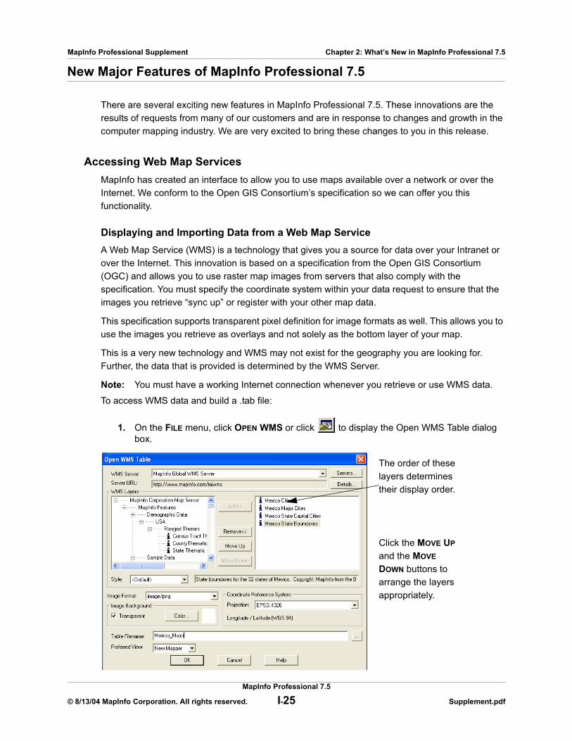
1. On the FILE menu, click OPEN WMS or click to display the Open WMS Table dialog box.
The order of these layers determines their display order.
Click the MOVE UP and the MOVE DOWN buttons to arrange the layers appropriately.
MapInfo Professional 7.5
© 8/13/04 MapInfo Corporation. All rights reserved. I-25 Supplement.pdf
MapInfo Professional Supplement Chapter 2: What’s New in MapInfo Professional 7.5
Note: The WMS Servers that display in the WMS Server list are based on a list we have compiled for you. MapInfo has no control over the availability of these servers at any given time. The availability of WMS data depends upon the status of the server and the status of the maps on those servers. You can customize this list to suit your needs.
2. To work with the layers from a particular server, select a WMS Server from the WMS Servers drop-down list.To see the details of a particular WMS Server, including the Server URL, the Server Name, version, and usually a server supplied description, click DETAILS.
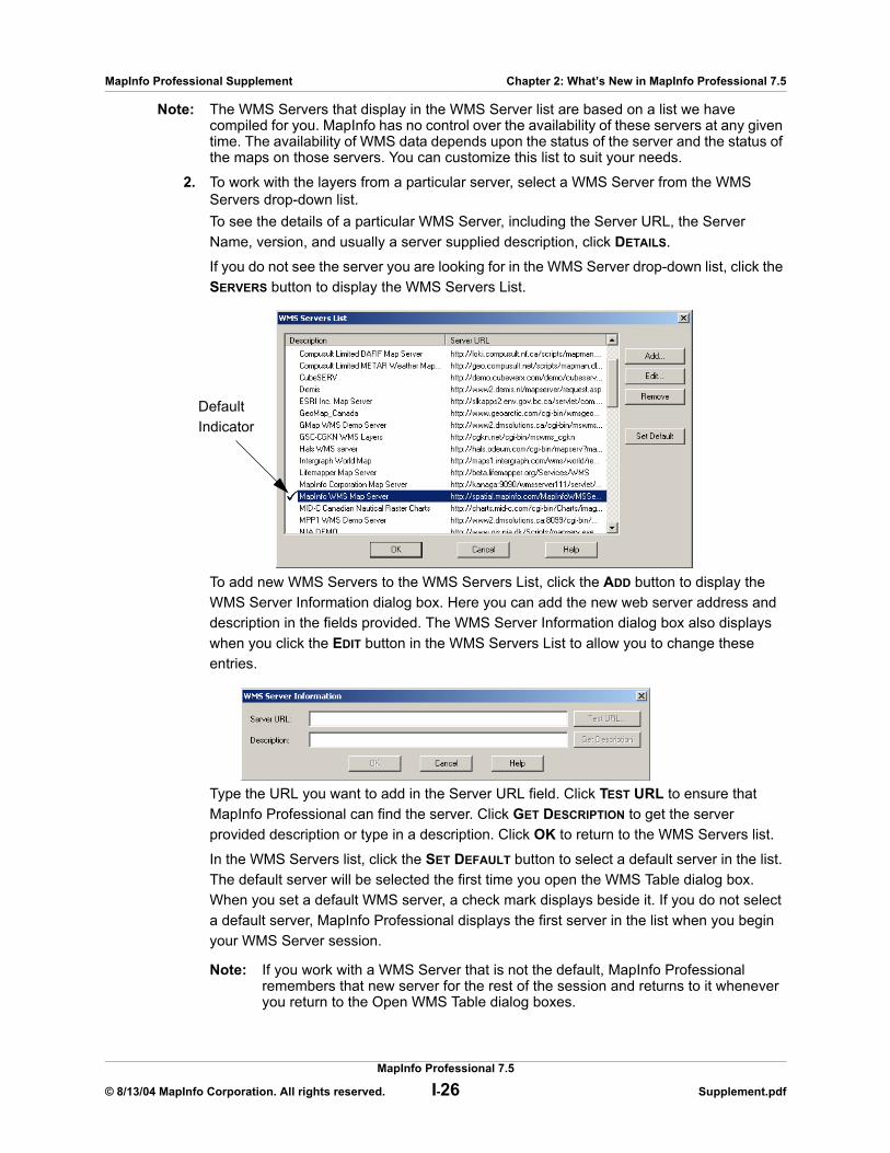
If you do not see the server you are looking for in the WMS Server drop-down list, click the SERVERS button to display the WMS Servers List.
To add new WMS Servers to the WMS Servers List, click the ADD button to display the WMS Server Information dialog box. Here you can add the new web server address and description in the fields provided. The WMS Server Information dialog box also displays when you click the EDIT button in the WMS Servers List to allow you to change these entries.
Type the URL you want to add in the Server URL field. Click TEST URL to ensure that MapInfo Professional can find the server. Click GET DESCRIPTION to get the server provided description or type in a description. Click OK to return to the WMS Servers list.
In the WMS Servers list, click the SET DEFAULT button to select a default server in the list. The default server will be selected the first time you open the WMS Table dialog box. When you set a default WMS server, a check mark displays beside it. If you do not select a default server, MapInfo Professional displays the first server in the list when you begin your WMS Server session.
Note: If you work with a WMS Server that is not the default, MapInfo Professional remembers that new server for the rest of the session and returns to it whenever you return to the Open WMS Table dialog boxes.
Default Indicator
MapInfo Professional 7.5
© 8/13/04 MapInfo Corporation. All rights reserved. I-26 Supplement.pdf

MapInfo Professional Supplement Chapter 2: What’s New in MapInfo Professional 7.5
3. When you have completed your work in the WMS Servers List, click OK to return to the Open WMS Table dialog box.
4. Review the list of available layers for the server you selected and do one of the following:• Double-click one or more layer(s) you want to retrieve in the WMS Layers list to move
them to the right pane• Click each layer you want to retrieve from the server and click ADD to move them to
the right pane
Note: The topmost layers display over the bottom most layers.
5. Decide how you want to use these WMS server layers and do one of the following:• To create a single .tab file with several WMS layers in it, select all of the layers for that
.tab file so they display in the right pane. Then organize them in the order you want them to display using the MOVE UP and MOVE DOWN buttons.
• To create individual .tab files for the WMS server layers you want, select one layer at a time, select the appropriate Style, Format, and Projection options from their drop-down lists and save the .tab file. Repeat this process for each layer you want to retrieve.
Using either method, you move the layer(s) you selected to the right pane. The Style, Projection, and Image Format information associated this layer or layers change to reflect either the attributes of the single layer or the attributes that all the layers have in common. We describe the process for changing and selecting these attributes below.
Note: To remove a layer from the list in the right pane, select the layer you want to remove and click the REMOVE button.
6. If there are styles associated with the layer(s) you selected, they display in the STYLE drop-down list. Styles indicate the visual display options available with this layer and are supplied by the web server. Initially, we display the selected layer in the server’s default style. The style that displays pertains to the currently selected layer.To change the style of a layer, click it in the left or right pane and select the style from the STYLE drop-down list. The styles you select for a layer do not pertain to any other layer in the list.
Note: You can also change these image display style attributes later (on the MAP menu, point to LAYER CONTROL and click DISPLAY override options. In this dialog box you can change the image’s translucency and transparency as well as other raster display properties available in MapInfo Professional.
7. Choose a format for the layer from the IMAGE FORMAT drop-down list. The options that display in this list may differ depending upon the formats the server supports and the formats we support. We support: PNG, JPEG (JPG), TIFF (GeoTIFF and TIFF) and GIF formats, in that order of priority.
8. To change the background options, specify them in the IMAGE BACKGROUND box. To make the background of your layer transparent, click the TRANSPARENT check box and select the color of the background. Click the COLOR button to display the list of colors.
Note: The more color depth the image has, the more difficulty you have isolating the background for transparency purposes. If you experience problems with transparency with one image format, try another, if it is available.
9. The COORDINATE REFERENCE SYSTEM PROJECTIONS drop-down list displays all of the projections that the selected layers have in common. This list is disabled when the selected layers do not have any projections in common. If the PROJECTIONS drop-down list is disabled, you cannot make a map request.
MapInfo Professional 7.5
© 8/13/04 MapInfo Corporation. All rights reserved. I-27 Supplement.pdf

MapInfo Professional Supplement Chapter 2: What’s New in MapInfo Professional 7.5
Note: To enable this list, try removing layers one at a time to see if the problem is caused by layers not having projections in common.
10. To enter a name for this table, do one of the following:
• Click the button at the end of the TABLE FILENAME field to display the Please specify a TAB filename dialog box. Select the path and type the file name in the FILENAME field and click OK.
• Type the path into the TABLE FILENAME field
Note: There are three conditions that might prevent you from saving the .tab file at this point. To save the .tab file you must:
a. Select at least one valid layer from the WMS Server listb. Layer(s) must contain a supported projectionc. Type a valid .tab file name
11. Select the view for this map in the PREFERRED VIEW drop-down list to determine where the WMS table should display after you open it. Options include: Automatic, Current Mapper, New Mapper, and No View.
12. Click OK to generate the WMS map request.
Once you have saved a WMS table name, you can change its WMS layer settings using the WMS Table Properties dialog box. To access this dialog box, go to the TABLE menu and click WMS TABLE PROPERTIES. When the WMS Table Properties dialog box displays, select the layer you want to edit and change the settings for that layer. You can also add, remove, and reorder the WMS layers, change the projection, image formats, and background options of the layers. Remember, you can edit the display attributes for the WMS table using Display Style override commands in Layer Control.
How Does MapInfo Professional Use WMS Servers?When you create a .tab file from WMS Server layer(s), you are actually creating a pointer to an XML file that keeps track of the data you selected, (the server address, the selected layer(s), the styles, the format, and the projection settings). You never actually retrieve the data and save it on your computer. Every time you add a WMS Server table as a layer in a Map window or you change the view of the Map, the system generates a map request and retrieves the layer information. To do this, the .tab file points to an XML file which retrieves the information from the WMS Server and displays it on your computer. If you are not connected to the Internet, the server is unavailable, or the WMS layer(s) you are retrieving are not available, you cannot use the WMS .tab file.
Projection Issues Associated with WMSThe coordinate system used in the map image is very important. It is what enables various layers to line up properly. Make sure you retrieve WMS Server images that you can use with the other maps you use. Keep in mind that the raster layer always determines the projection of the map. If there is more than one raster layer in a map, the largest raster layer determines the projection of the map.
Raster Registration EnhancementsWe have enhanced the raster registration process to make it quicker and easier to use.
MapInfo Professional 7.5
© 8/13/04 MapInfo Corporation. All rights reserved. I-28 Supplement.pdf
MapInfo Professional Supplement Chapter 2: What’s New in MapInfo Professional 7.5
Registering the Coordinates of a Raster Image Before you can overlay vector data on top of a raster image, you must first register the raster image so that MapInfo Professional can position it properly in a Map window. In the Image Registration dialog box, you can identify control point coordinates and specify the appropriate projection for the raster image.
Control points are the coordinates you identify on the raster image that MapInfo Professional can use later to match up to other layers. It is very important to provide accurate control point information when registering a raster image, so MapInfo Professional can display raster images without distorting or rotating them. Later, when you overlay vector data, MapInfo Professional distorts and rotates the vector data so both layers can line up properly. Identifying significant control points makes this match up process easier. We suggest you use highway/street intersections and prominent landmarks as control points, as they rarely move.
Specifying the correct projection of the raster image is also important for accurate display. Images that do not have known projections, such as unrectified aerial photographs, are less suitable for use with vector data.
There are two ways to register a raster image in MapInfo Professional. Each involves specifying the map coordinates of control points on a reference map and matching them with equivalent points on the raster image. To determine map coordinates, you can:
• Identify a point’s coordinates from the paper map.• Determine a raster images control point coordinates on screen and automatically transfer
the information to the Image Registration dialog box.
Note: If you scanned in the image from a paper map, the map most likely contains a graticule (latitude and longitude grid). You can choose those coordinates for prominent features and enter them in the Image Registration dialog box.
To register the coordinates of a raster image and create a .tab file from the raster image:
1. On the FILE menu, click OPEN and specify the Raster Image file format in the Files of type drop-down list.
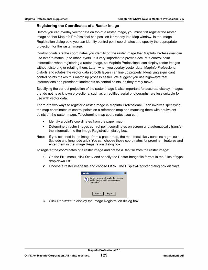
2. Choose a raster image file and choose OPEN. The Display/Register dialog box displays.
3. Click REGISTER to display the Image Registration dialog box.
MapInfo Professional 7.5
© 8/13/04 MapInfo Corporation. All rights reserved. I-29 Supplement.pdf

MapInfo Professional Supplement Chapter 2: What’s New in MapInfo Professional 7.5
4. Choose the PROJECTION button to specify the raster image’s projection. It is easier to match up the maps if you select the same projection for the raster image as the vector images (layers) you want to use. Choosing the same projection minimizes image distortion when overlaying the vector map layers. You cannot change the projection from the Map window.
Note: If you do not set the projection, MapInfo Professional defaults to Longitude/Latitude or to the default table projection set by using the map window preferences you set.
5. You can set the units for the control point entries by clicking the UNITS button.6. To select the actual coordinates to register in the raster image, click the ADD button to add
a new entry into the CONTROL POINTS list box. The Add Control Point dialog box displays.
7. Specify the coordinates from the paper map in the dialog box. The location of each point is marked on the preview image with a “+” symbol. You can change the Label to something more meaningful to you, such as US85/LA132, to describe an intersection in the raster map. You might also select a prominent building or other very specific address that is easily identifiable in both maps.
8. Repeat this process (step 6 and step 7) until you have registered at least three or four points on the raster image. Try to vary the position of these control points to better define the map. If too many points are in a straight line, an error displays.If you are working with an image for which you do not know the projection (such as an aerial photograph), enter at least three control points to improve accuracy.
Control Points list box
Preview of Raster Image
MapInfo Professional 7.5
© 8/13/04 MapInfo Corporation. All rights reserved. I-30 Supplement.pdf
MapInfo Professional Supplement Chapter 2: What’s New in MapInfo Professional 7.5
9. When you have completed your control point entries, click OK. The raster image displays as a .tab file.Use the + and - buttons to zoom in and out of the raster image. Zooming in on the image may help you obtain greater accuracy in control point location. If you are having difficulty finding a control point in the Image Registration image, click the control point entry in the Image Registration list and click the FIND button to display the point in the image.
Transferring Vector Map Coordinates Directly to a Raster MapTo transfer the coordinates automatically from a vector map to a raster image, you need a vector map of the same image. Then, you display the vector map side by side with the Image Registration dialog box, which shows a preview of the raster image. Click a prominent feature in the vector map to determine its coordinates and transfer this control point to the Image Registration dialog box.
To transfer a vector map’s coordinates to a raster image:
1. On the FILE menu, click OPEN and Raster Image file format. 2. Choose the raster image file and click OPEN. The Display/Register dialog box displays. 3. Click REGISTER. The Image Registration dialog box displays. A preview of the raster image
appears in the lower half of the dialog box.4. Choose the PROJECTION button to specify the image’s projection. If you do not set the
projection, MapInfo Professional defaults to Longitude/Latitude or to the default table projection set in the Map Window Preferences.
5. To add control points, click the ADD button to add a control point entry to the Control Points list.
6. Click the PICK FROM MAP button and select a location in the Map window that matches a location in your raster image. MapInfo Professional updates the Map X and Map Y fields in the Edit Control dialog box with the new coordinates. Click OK to save this entry and close the dialog box.
7. Click the entry in the CONTROL POINTS list and click the matching control point location in the image pane. The Edit Control Point dialog box displays showing the control point’s location in pixels in the Image X and Image Y fields. Click OK to save these entries.
Note: Remember to type a meaningful description of this location in the LABEL field.
8. Repeat this process until you have identified three or four non-linear points in the preview pane of the Image Registration dialog box.
9. After you have defined all of the control points, click OK in the Image Registration dialog box. The raster image displays in the Map window under the vector layer. Use the Layer Control feature to position the raster map appropriately with your vector layers.
Create Points ChangesWe have added two new enhancements to the Create Points functionality. The first change: you can optionally use numeric data in non-numeric columns (i.e. columns with a character-based format). We made this change to make it easier to create points from sources where the numeric values appear in columns not specifically flagged as numeric. The second change allows you to replace existing objects with new point objects without deleting the existing geographic data first. You do not have to clear the Table is Mappable check box in the Table Structure window to get these results.
MapInfo Professional 7.5
© 8/13/04 MapInfo Corporation. All rights reserved. I-31 Supplement.pdf
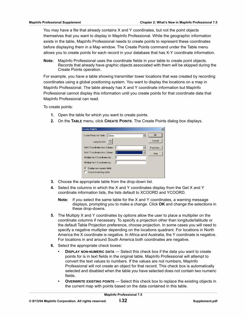
MapInfo Professional Supplement Chapter 2: What’s New in MapInfo Professional 7.5
You may have a file that already contains X and Y coordinates, but not the point objects themselves that you want to display in MapInfo Professional. While the geographic information exists in the table, MapInfo Professional needs to create points to represent these coordinates before displaying them in a Map window. The Create Points command under the Table menu allows you to create points for each record in your database that has X-Y coordinate information.
Note: MapInfo Professional uses the coordinate fields in your table to create point objects. Records that already have graphic objects associated with them will be skipped during the Create Points operation.
For example, you have a table showing transmitter tower locations that was created by recording coordinates using a global positioning system. You want to display the locations on a map in MapInfo Professional. The table already has X and Y coordinate information but MapInfo Professional cannot display this information until you create points for that coordinate data that MapInfo Professional can read.
To create points:
1. Open the table for which you want to create points.2. On the TABLE menu, click CREATE POINTS. The Create Points dialog box displays.
3. Choose the appropriate table from the drop-down list. 4. Select the columns in which the X and Y coordinates display from the Get X and Y
coordinate information lists, the lists default to XCOORD and YCOORD.
Note: If you select the same table for the X and Y coordinates, a warning message displays, prompting you to make a change. Click OK and change the selections in these drop-downs.
5. The Multiply X and Y coordinates by options allow the user to place a multiplier on the coordinate columns if necessary. To specify a projection other than longitude/latitude or the default Table Projection preference, choose projection. In some cases you will need to specify a negative multiplier depending on the locations quadrant. For locations in North America the X coordinate is negative. In Africa and Australia, the Y coordinate is negative. For locations in and around South America both coordinates are negative.
6. Select the appropriate check boxes:• DISPLAY NON-NUMERIC DATA — Select this check box if the data you want to create
points for is in text fields in the original table. MapInfo Professional will attempt to convert the text values to numbers. If the values are not numbers, MapInfo Professional will not create an object for that record. This check box is automatically selected and disabled when the table you have selected does not contain two numeric fields.
• OVERWRITE EXISTING POINTS — Select this check box to replace the existing objects in the current map with points based on the data contained in this table.
MapInfo Professional 7.5
© 8/13/04 MapInfo Corporation. All rights reserved. I-32 Supplement.pdf
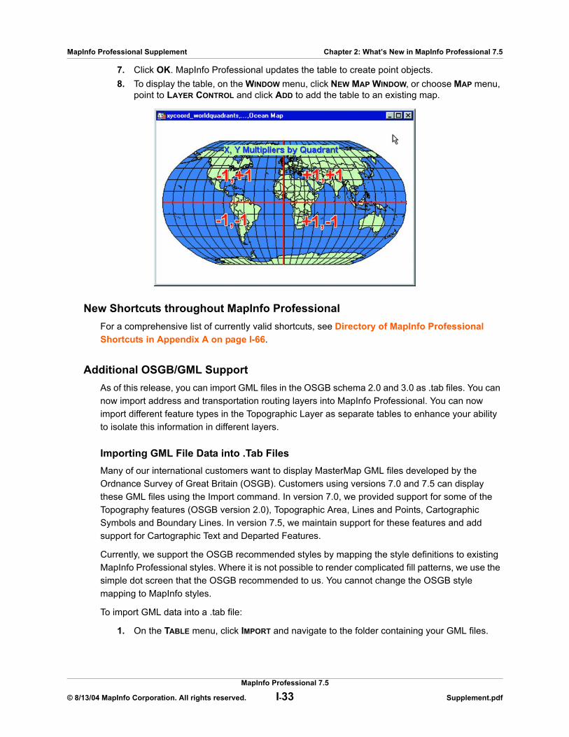
MapInfo Professional Supplement Chapter 2: What’s New in MapInfo Professional 7.5
7. Click OK. MapInfo Professional updates the table to create point objects.8. To display the table, on the WINDOW menu, click NEW MAP WINDOW, or choose MAP menu,
point to LAYER CONTROL and click ADD to add the table to an existing map.
New Shortcuts throughout MapInfo ProfessionalFor a comprehensive list of currently valid shortcuts, see Directory of MapInfo Professional Shortcuts in Appendix A on page I-66.
Additional OSGB/GML SupportAs of this release, you can import GML files in the OSGB schema 2.0 and 3.0 as .tab files. You can now import address and transportation routing layers into MapInfo Professional. You can now import different feature types in the Topographic Layer as separate tables to enhance your ability to isolate this information in different layers.
Importing GML File Data into .Tab FilesMany of our international customers want to display MasterMap GML files developed by the Ordnance Survey of Great Britain (OSGB). Customers using versions 7.0 and 7.5 can display these GML files using the Import command. In version 7.0, we provided support for some of the Topography features (OSGB version 2.0), Topographic Area, Lines and Points, Cartographic Symbols and Boundary Lines. In version 7.5, we maintain support for these features and add support for Cartographic Text and Departed Features.
Currently, we support the OSGB recommended styles by mapping the style definitions to existing MapInfo Professional styles. Where it is not possible to render complicated fill patterns, we use the simple dot screen that the OSGB recommended to us. You cannot change the OSGB style mapping to MapInfo styles.
To import GML data into a .tab file:
1. On the TABLE menu, click IMPORT and navigate to the folder containing your GML files.
MapInfo Professional 7.5
© 8/13/04 MapInfo Corporation. All rights reserved. I-33 Supplement.pdf
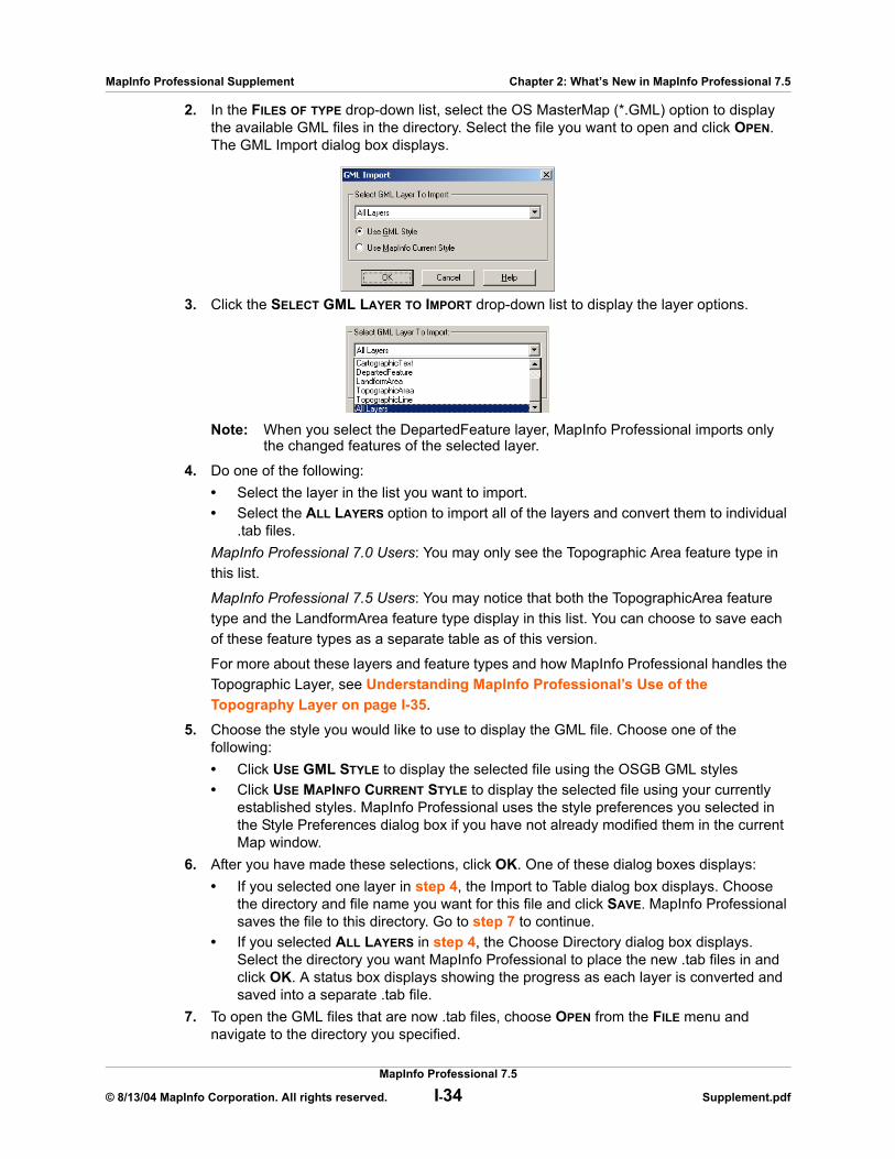
MapInfo Professional Supplement Chapter 2: What’s New in MapInfo Professional 7.5
2. In the FILES OF TYPE drop-down list, select the OS MasterMap (*.GML) option to display the available GML files in the directory. Select the file you want to open and click OPEN. The GML Import dialog box displays.
3. Click the SELECT GML LAYER TO IMPORT drop-down list to display the layer options.
Note: When you select the DepartedFeature layer, MapInfo Professional imports only the changed features of the selected layer.
4. Do one of the following:• Select the layer in the list you want to import.• Select the ALL LAYERS option to import all of the layers and convert them to individual
.tab files.MapInfo Professional 7.0 Users: You may only see the Topographic Area feature type in this list.
MapInfo Professional 7.5 Users: You may notice that both the TopographicArea feature type and the LandformArea feature type display in this list. You can choose to save each of these feature types as a separate table as of this version.
For more about these layers and feature types and how MapInfo Professional handles the Topographic Layer, see Understanding MapInfo Professional’s Use of the Topography Layer on page I-35.
5. Choose the style you would like to use to display the GML file. Choose one of the following:• Click USE GML STYLE to display the selected file using the OSGB GML styles• Click USE MAPINFO CURRENT STYLE to display the selected file using your currently
established styles. MapInfo Professional uses the style preferences you selected in the Style Preferences dialog box if you have not already modified them in the current Map window.
6. After you have made these selections, click OK. One of these dialog boxes displays:• If you selected one layer in step 4, the Import to Table dialog box displays. Choose
the directory and file name you want for this file and click SAVE. MapInfo Professional saves the file to this directory. Go to step 7 to continue.
• If you selected ALL LAYERS in step 4, the Choose Directory dialog box displays. Select the directory you want MapInfo Professional to place the new .tab files in and click OK. A status box displays showing the progress as each layer is converted and saved into a separate .tab file.
7. To open the GML files that are now .tab files, choose OPEN from the FILE menu and navigate to the directory you specified.
MapInfo Professional 7.5
© 8/13/04 MapInfo Corporation. All rights reserved. I-34 Supplement.pdf
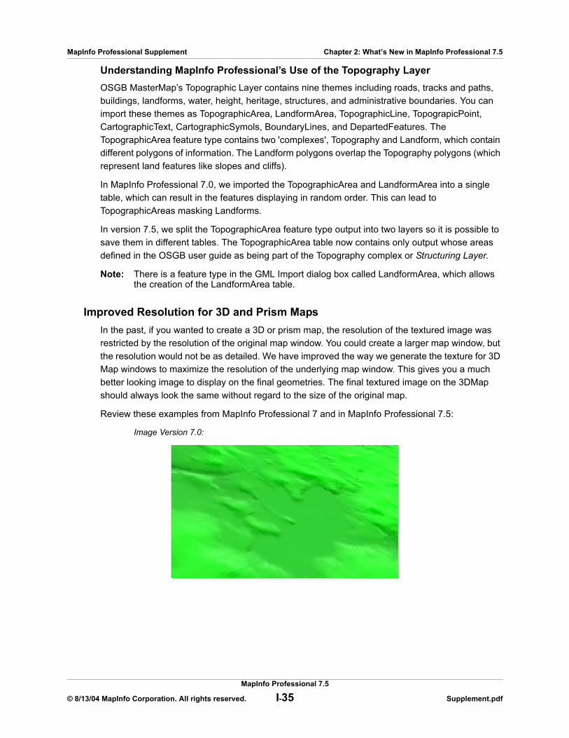
MapInfo Professional Supplement Chapter 2: What’s New in MapInfo Professional 7.5
Understanding MapInfo Professional’s Use of the Topography LayerOSGB MasterMap’s Topographic Layer contains nine themes including roads, tracks and paths, buildings, landforms, water, height, heritage, structures, and administrative boundaries. You can import these themes as TopographicArea, LandformArea, TopographicLine, TopograpicPoint, CartographicText, CartographicSymols, BoundaryLines, and DepartedFeatures. The TopographicArea feature type contains two 'complexes', Topography and Landform, which contain different polygons of information. The Landform polygons overlap the Topography polygons (which represent land features like slopes and cliffs).
In MapInfo Professional 7.0, we imported the TopographicArea and LandformArea into a single table, which can result in the features displaying in random order. This can lead to TopographicAreas masking Landforms.
In version 7.5, we split the TopographicArea feature type output into two layers so it is possible to save them in different tables. The TopographicArea table now contains only output whose areas defined in the OSGB user guide as being part of the Topography complex or Structuring Layer.
Note: There is a feature type in the GML Import dialog box called LandformArea, which allows the creation of the LandformArea table.
Improved Resolution for 3D and Prism MapsIn the past, if you wanted to create a 3D or prism map, the resolution of the textured image was restricted by the resolution of the original map window. You could create a larger map window, but the resolution would not be as detailed. We have improved the way we generate the texture for 3D Map windows to maximize the resolution of the underlying map window. This gives you a much better looking image to display on the final geometries. The final textured image on the 3DMap should always look the same without regard to the size of the original map.
Review these examples from MapInfo Professional 7 and in MapInfo Professional 7.5:
Image Version 7.0:
MapInfo Professional 7.5
© 8/13/04 MapInfo Corporation. All rights reserved. I-35 Supplement.pdf
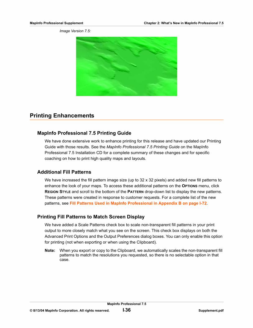
MapInfo Professional Supplement Chapter 2: What’s New in MapInfo Professional 7.5
Image Version 7.5:
Printing Enhancements
MapInfo Professional 7.5 Printing GuideWe have done extensive work to enhance printing for this release and have updated our Printing Guide with those results. See the MapInfo Professional 7.5 Printing Guide on the MapInfo Professional 7.5 Installation CD for a complete summary of these changes and for specific coaching on how to print high quality maps and layouts.
Additional Fill PatternsWe have increased the fill pattern image size (up to 32 x 32 pixels) and added new fill patterns to enhance the look of your maps. To access these additional patterns on the OPTIONS menu, click REGION STYLE and scroll to the bottom of the PATTERN drop-down list to display the new patterns. These patterns were created in response to customer requests. For a complete list of the new patterns, see Fill Patterns Used in MapInfo Professional in Appendix B on page I-72.
Printing Fill Patterns to Match Screen DisplayWe have added a Scale Patterns check box to scale non-transparent fill patterns in your print output to more closely match what you see on the screen. This check box displays on both the Advanced Print Options and the Output Preferences dialog boxes. You can only enable this option for printing (not when exporting or when using the Clipboard).
Note: When you export or copy to the Clipboard, we automatically scales the non-transparent fill patterns to match the resolutions you requested, so there is no selectable option in that case.
MapInfo Professional 7.5
© 8/13/04 MapInfo Corporation. All rights reserved. I-36 Supplement.pdf

MapInfo Professional Supplement Chapter 2: What’s New in MapInfo Professional 7.5
Setting your Output Setting PreferencesThe Output Settings allow you to control raster and grid file color settings for on-screen display, printed output, and file export settings. In addition, you can also specify how you want to handle transparency in vector and raster files in both your printed output and exported files. Other printer settings enable you to specify an output method, map scaling, and whether to print a border around a Map window.
You can override the settings in the Output settings preferences in the Advanced Printing dialog box. These preferences represent the default settings used in the Advanced Printing dialog box. These new settings can then be saved in a workspace.
Note: You can get additional printer advice in the MapInfo Professional Printing Guide on the MapInfo Professional 7.5 Installation CD.
To set your output preferences:
1. On the OPTIONS menu, point to PREFERENCES and click OUTPUT SETTINGS to display the Output Preferences dialog box.
2. The DISPLAY settings control the on-screen display of a raster or grid file. Click the appropriate output settings based on your output requirements.These entries explain the display settings, the printing options, and window export options in this dialog. Some of the options appear in more than one dialog so we have grouped all of the like explanations together.
• DISPLAY RASTER IN TRUE COLOR WHEN POSSIBLE — Click this check box to display your 24-bit raster or grid file images in true color (make sure your display settings are set to greater than 256 colors). Clear this check box if you only want your images to display using 256 colors. This box is checked by default.
• DITHER METHOD — Dithering is a technique that blends pixels electronically to improve the look of an image. Click a dither method when you are converting a 24-bit image to 256 colors.
MapInfo Professional 7.5
© 8/13/04 MapInfo Corporation. All rights reserved. I-37 Supplement.pdf

MapInfo Professional Supplement Chapter 2: What’s New in MapInfo Professional 7.5
Dithering creates the illusion of complex colors by using a pattern of finite (fixed) color dots. For example, to create the color green using dithering, the color would consist of a pattern of yellow and blue dots.
HALFTONE dithering calculates a series of half tone differences in color between high- contrast elements in your image to create a smooth transition of color. This option is selected by default for display, print, and export options.
ERROR DIFFUSION dithering calculates an interim color between contrasting colors and shades the surrounding pixels to blend evenly toward that interim color.
Note: You can select dither method options in the display, printing, and exporting sections of this dialog box. The same definitions apply to each area.
3. The PRINTING settings control the printing options for Map windows, Layout windows and all other output file types. Select the appropriate printing settings based on your output requirements. Remember that resetting these printer options locally overrides these preferences.• OUTPUT METHOD/PRINT DIRECTLY TO DEVICE — Click this option to print your image file
directly from MapInfo Professional as you did when you were using MapInfo Professional 6.0 or earlier. This check box is checked by default.
• OUTPUT METHOD/PRINT USING ENHANCED METAFILE — Click this option to generate an enhanced metafile of your MapInfo Professional image before sending it to the printer. This setting takes advantage of current printer technology to shrink the spool size and print your file quicker without sacrificing quality.
Note: You must use this setting if you are printing a map containing a translucent raster or grid layer. If you do not use this setting, the image will not print translucently.
• PRINT BORDER FOR MAP WINDOW — Click this check box to print a black border around the image you are printing. Clear this check box to leave the image unbordered. This check box is checked by default.
• INTERNAL HANDLING FOR PRINTING TRANSPARENT VECTOR FILLS AND SYMBOLS — Special programming has been added to handle transparent fill patterns and bitmaps for vector images when printing or exporting. Click this check box to use this functionality or clear it to let the printer or Windows export functions to handle this. This check box is checked by default.
• SCALE PATTERNS — Select this check box to match the non-transparent fill patterns in your print output to more closely match what you see on your screen. This check box is checked by default. Clear this check box to let the printer driver have exclusive control over rendering the pattern fills.
Note: The Scale Patterns check box does not affect transparent fill patterns because transparent fill patterns are always scaled.
• USE ROP METHOD TO DISPLAY TRANSPARENT RASTER — Click this check box to allow the internal ROP (Raster Overlay by Pixel) to manage the transparent pixel display and printing in raster images. Since the ROP Method is largely a display method, not all printers, plotters, and export programs can use it. We recommend that you either check with the printer manufacturer before using this setting or try a few test prints or exports to get the results you want. This check box is cleared by default.Using the ROP method may not produce problems unless you print the metafile.
• PRINT/EXPORT RASTER IN TRUE COLOR WHEN POSSIBLE — Click this check box to print and export your 24-bit raster or grid file images in true color (make sure your printer settings are set to greater than 256 colors). Clear this check box if you are not working with a color printer. This check box is checked by default.
MapInfo Professional 7.5
© 8/13/04 MapInfo Corporation. All rights reserved. I-38 Supplement.pdf
MapInfo Professional Supplement Chapter 2: What’s New in MapInfo Professional 7.5
Note: See the Dither Method setting above for details about this option.
4. The WINDOW EXPORT settings control the export options for Map windows, Layout windows and all other output file types. Select the appropriate window export settings based on your output requirements. Remember that resetting these options locally overrides these preferences.• EXPORT BORDER — Click this check box to include a black border on images you are
exporting. Clear this check box to export the image without a border. This check box is checked by default.
Note: The preference setting definitions for Internal Handling for Transparent Vector Fills and Symbols, Use ROP Method to Display Transparent Raster, Print Raster in True Color When Possible, and Dithering Methods are the same for export as for printing above.
5. Click OK to save these settings and return to the Preferences dialog box.6. Click OK to close the Preferences dialog box.
Recommendations for Effective Pattern ScalingWhen you are printing, find out what type of printer driver you are using. Many PCL6 and some HPGL drivers handle fill pattern scaling and give you control over this feature. Turning off their scaling may be the difference between what you see in print and what you see on your monitor. We recommend that you try turning off your driver’s scaling options and try ours first, because we have enhanced our method to more meet your Layout window requirements. To turn our pattern scaling options on, check the SCALE PATTERNS check box in the Output Preferences dialog box. Then try turning off our scaling and turn theirs back on and see what you like better. Our tests show that our scaling will give you better matching results and when doing color output, our scaling also produces better color output.
If you are printing to postscript drivers using LanguageLevel 2 or 3, we find that some of the Microsoft drivers did not support pattern scaling. As a result, our scaling method may not help you. Microsoft recommended that you reset the language level of the postscript driver to LanguageLevel 1 to remove this restriction. We did find some exceptions to this condition. On Windows 2000 and Windows NT, some HP Laser Jet and Color Laser Jet postscript drivers using our scaling option printed correctly.
Database Enhancements
Reading Larger Excel Files into MapInfo ProfessionalWe have expanded the range limit in the product to support the 64K row limit currently supported in Excel. There used to be a 32K row limit but we have been able to expand our support to include these larger files.
MapInfo Professional 7.5
© 8/13/04 MapInfo Corporation. All rights reserved. I-39 Supplement.pdf

MapInfo Professional Supplement Chapter 2: What’s New in MapInfo Professional 7.5
Read Oracle Tables in 8.1.7 like 9iIn the past, Oracle 8i clients could not open three dimensional SDO objects in MI Pro. Traditionally, we have read these objects in Oracle 9i but not for 8i. The product was only indexing tables on two dimensions for customers using Oracle 8.1.7. We recommend that you index your columns with the default /3D index to ensure that your queries do not fail.
Datum Enhancements
Enhanced KKJ Projection AlgorithmFor this release, we have significantly improved the KKJ projection algorithm using conversion formulas from the National Land Survey of Finland.
Japanese Geodetic Datum ConversionIn the late 90’s, Japan started using new parameters for its Tokyo datum, which are somewhat different from those in the previous version of the product. In MapInfo Professional 7.5, we have added a new datum, which uses the JGD2000 conversion to convert the old Tokyo datum (the NIMA Tokyo datum (1991)) and the “new” Tokyo datum to the JGD2000 datum. If the JGD2000 conversion fails (for example, when a point is outside the JGD2000 grid), we use the standard Molodensky transformation method. See Tokyo97 in Appendix B in the MapInfo Professional User’s Guide (Unabridged).
Mapping Enhancements
Clearing Default Workspace Name After Close AllWe have corrected a file overwriting problem you might have seen using the Close All option. In the past when you saved your workspace, selected Close All, and then saved another workspace, MapInfo Professional failed to recognize that you were working in a different workspace. It would automatically prompt you to save with the same name as you had previously entered, running the risk of overwriting the other saved workspace. We have changed this process to clear the name of the last saved workspace after the Close All selection. The default workspace filename is now UNTITLED.WOR.
Moving and Offsetting Geographic ObjectsWe have made it easier and quicker to move and offset an object or a group of objects in Version 7.5. The offset / move functionality is available when any layer is editable however, you can only move an object within its editable layer. You can always use the copy feature as long as a layer is editable. Instead of moving the selected object one pixel at a time, the Arrow keys now allow you to pan the map. We have added keystroke instructions to move objects more precisely on the
MapInfo Professional 7.5
© 8/13/04 MapInfo Corporation. All rights reserved. I-40 Supplement.pdf

MapInfo Professional Supplement Chapter 2: What’s New in MapInfo Professional 7.5
map. To move an object one pixel at a time, click it and press and hold the CTRL key and press the ARROW button corresponding to the direction you want the object to move. To move the object 10 pixels at a time, press and hold the CTRL and SHIFT keys and press the ARROW button corresponding to the direction you want the object to move.
Positioning and Sizing your Map ObjectsTo move an object to a new location, make the object’s layer editable and click the object to select it. Hold down the mouse button for at least one second until the cursor turns into a four-headed arrow. Drag the object to its new location and release the button. The object maintains its shape.
To move an object (in an editable layer) one pixel at a time, click it and press and hold the CTRL key and press the ARROW button corresponding to the direction you want the object to move. To move the object 10 pixels at a time, press and hold the CTRL and SHIFT keys and press the ARROW button corresponding to the direction you want the object to move.
Also, if you click the on the fifth edit handle (rotate handle) and hold down the mouse button, you can rotate the highlighted box to the desired angle. A rubber banding box is drawn representing the bounds of the rotated object. If you press and hold SHIFT key while the rubber banding box is being drawn, the rotation will be limited to 45 degree increments.
Moving Objects on the MapYou can move selected objects within its editable map layer easily.
To move an object on the map:
1. Click your map to make it active. 2. Make the layer where the object is located editable (on the MAP menu, click LAYER
CONTROL).3. Select the object(s) using the Select tool.
If you select more than one object at a time to move, the objects move in the same way. Take care to ensure that you do not move an object off the map or off land by mistake.
Note: When you move the objects, you move them all at once, maintaining their positions relative to one another.
4. Do one or all of the following:• To move the selected object(s) using the mouse, hold down the mouse button and
drag the object to its new location• To move the selected object(s) one screen pixel at a time, press and hold the CTRL
key and press the ARROW key in the direction you want the object(s) to move• To move the selected object(s) 10 screen pixels at a time, press and hold the CTRL
and SHIFT keys and press the ARROW key in the direction you want the object(s) to move
Note: Since the moves are made in screen pixels, the zoom level affects how far the object is moved.
Offsetting Objects on the MapThe Offset feature makes a copy of the object(s) you select from the original source object(s) and saves them in the original data file.
MapInfo Professional 7.5
© 8/13/04 MapInfo Corporation. All rights reserved. I-41 Supplement.pdf
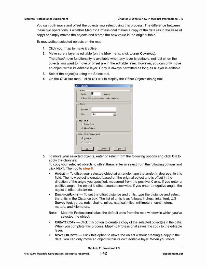
MapInfo Professional Supplement Chapter 2: What’s New in MapInfo Professional 7.5
You can both move and offset the objects you select using this process. The difference between these two operations is whether MapInfo Professional makes a copy of the data (as in the case of copy) or simply moves the objects and stores the new value in the original table.
To move/offset selected objects on the map:
1. Click your map to make it active. 2. Make sure a layer is editable (on the MAP menu, click LAYER CONTROL).
The offset/move functionality is available when any layer is editable, not just when the objects you want to move or offset are in the editable layer. However, you can only move an object within its editable layer. Copy is always permitted as long as a layer is editable.
3. Select the object(s) using the Select tool. 4. On the OBJECTS menu, click OFFSET to display the Offset Objects dialog box.
5. To move your selected objects, enter or select from the following options and click OK to apply the changes. To copy your selected objects to offset them, enter or select from the following options and click NEXT. Then go to step 6.• ANGLE — To offset your selected object at an angle, type the angle (in degrees) in this
field. The new object is created based on the original object and is offset in the direction of the angle you specified, measured from the positive X-axis. If you enter a positive angle, the object is offset counterclockwise; if you enter a negative angle, the object is offset clockwise.
• DISTANCE/UNITS — To set the offset distance and units, type the distance and select the units in the Distance box. The list of units is as follows: inches, links, feet, U.S. Survey feet, yards, rods, chains, miles, nautical miles, millimeters, centimeters, meters, and kilometers.
Note: MapInfo Professional takes the default units from the map window in which you've selected the object.
• CREATE COPY — Click this option to create a copy of the selected object(s) in the data. When you complete this process, MapInfo Professional saves the copy to the editable layer.
• MOVE OBJECTS — Click this option to move the object without creating a copy in the data. You can only move an object within its own editable layer. When you move
MapInfo Professional 7.5
© 8/13/04 MapInfo Corporation. All rights reserved. I-42 Supplement.pdf

MapInfo Professional Supplement Chapter 2: What’s New in MapInfo Professional 7.5
objects, the Data Aggregation dialog box does not display, since you are only moving the data within the layer.
• COPY OR MOVE DISTANCE USING — The option you select in this box depends largely upon the projection of your source map. If your map has a latitude/longitude projection, MapInfo Professional enables the SPHERICAL type only. If you are working with a non-Earth projection, MapInfo Professional enables the CARTESIAN type only. When you click SPHERICAL, MapInfo Professional calculates the copy/move distance by mapping the data into a Latitude/Longitude On Earth projection.
When you click CARTESIAN, MapInfo Professional calculates the copy/move distance by considering the data to be projected to a flat surface and distances are measured using Cartesian distance calculations.
6. The Data Aggregation dialog box displays if one of these conditions are true:• You clicked the CREATE COPY option• You selected objects in a different table from the table associated with the editable
layer• The editable layer is not the cosmetic layer and has no text associated with the
geographical objects in itYou may notice that the only controls available to you in this dialog box are BLANK, VALUE, and NO DATA.
Type a value you will remember in the VALUE field of this dialog box. For more information about data aggregation, see Aggregating and Disaggregating Data in the MapInfo Professional 7.5 User Guide (Unabridged) on your MapInfo Professional 7.5 Installation CD.
7. Click OK to copy the data and offset the objects you selected.
Increase Memory Size and New Resolution Preference SettingYou can now set the number of bytes for the process in the System Settings Preferences dialog box. There used to be an processes limit of 100K, but we have set this new field to 1,000,000 bytes by default.
Now you can set the image resolution for export and Clipboard-placed graphics in the System Setting Preference dialog. This change affects the resolution of all the export options including the Save Window As option.
Setting your System PreferencesUse the System Settings Preferences dialog box to control the default settings that affect how MapInfo Professional interacts with your system.
To set your system settings preferences:
1. On the OPTIONS menu, point to PREFERENCES and click SYSTEM SETTINGS to display the System Settings Preferences dialog box.
MapInfo Professional 7.5
© 8/13/04 MapInfo Corporation. All rights reserved. I-43 Supplement.pdf

MapInfo Professional Supplement Chapter 2: What’s New in MapInfo Professional 7.5
2. Select the appropriate system preferences for your implementation of MapInfo Professional and click OK to save them.• COPY TO CLIPBOARD — Click the Copy to Clipboard check boxes to specify what items
you want to copy to the Clipboard: text, bitmaps, or metafiles. MapInfo Professional now copies metafiles in Enhanced Metafile format (EMF). All three are copied to the Clipboard by default. Clear the appropriate check box(es) to prevent the item from being copied to the clipboard.
• COLOR DEFAULTS — Select one of the Color Defaults preferences described below to control how MapInfo Professional shades thematic map layers.By default, MONITOR SETTING is selected. MapInfo Professional uses the color settings of the monitor to shade the map when this option is selected.
Click the BLACK & WHITE radio button if you are using a color monitor and want to shade your thematic map in gray-scale.
Click the COLOR radio button if you are using a black and white monitor and want to print a thematic map in color on a color printer.
• ASPECT RATIO ADJUSTMENT — Select the Aspect Ratio Adjustment options so that your map maintains the appropriate aspect ratio on your screen. Enter the dimensions of your screen in these fields.
• PAPER AND LAYOUT UNITS — Specify the Paper and Layout Units used when you measure the size of objects in a Layout window and the size of paper in the Print dialog boxes. The default is set to inches. You can choose: inches, picas, points, millimeters, and centimeters.
• NUMBER OF OBJECTS — You can only undo the last action. Set this option to the number of objects in the last action you want the system to Undo. For example, if you removed 10 objects at the same time and enter 10 in this field, MapInfo Professional undoes all 10.
Note: You cannot undo the following operations: Revert, Save, Save As, or Modify Table, or any operations whose effects are primarily cosmetic.
MapInfo Professional 7.5
© 8/13/04 MapInfo Corporation. All rights reserved. I-44 Supplement.pdf
MapInfo Professional Supplement Chapter 2: What’s New in MapInfo Professional 7.5
The default for this field is 10 objects. You can set it from 0 to 800. Setting the number of Undo objects to 0 deactivates the system. After you use the Undo option, the system toggles to REDO.
• MEMORY SIZE FOR UNDO — Type the number of bytes of memory you want to set aside for the Undo feature. This entry is set to 1,000,000 bytes by default. You can enter up to 10,000,000 bytes into this field. Increasing this entry may result in slower response time.
• DISPLAY PRE-VERSION 4 SYMBOLS USING THE TRUE TYPE FONT — Click this check box to indicate how you want to draw symbols from versions of MI Pro earlier than 4.0. Check this box to draw vector symbols with characters from the MapInfo Professional Symbols font. By default, vector symbols are drawn.
• WINDOW EXPORT AND CLIPBOARD RESOLUTION — To set the image resolution for exporting and Clipboard purposes, type the resolution in this field. MapInfo Professional uses this preference whenever you copy windows to the Clipboard, export your work to metafile and raster formats and the Save Window As export process as well. If you do not set this resolution manually, the product assumes 96 DPI. The maximum setting for this field is 1200 DPI.
• DATE WINDOW FOR 2 DIGIT YEARS — Select the appropriate Date Window for 2-Digit Years option for your purposes:Click the TURN DATE WINDOWING OFF radio button to use the current century for all 2-digit years. This option is selected by default.
Click the SET DATE WINDOW TO radio button to refer to dates in both the current century and the previous century. You need to use this setting if your data uses dates in the 1900s.
For example, if you type the number 30 in the Set Date Window field, 2-digit years from 00–29 are set in the 21st century (2000-2029), and 2-digit years from 30–99 are set in the 20th century (1930-1999).
3. Click OK to close the Preferences dialog box.
Zooming, Panning, and Moving ChangesWe have added new functionality to assist you in zooming and panning more precisely in the Map window. We have changed the function of the Arrow keys in the Map window to move objects in an editable layer.
In addition to the usual zoom keys on your Main Toolbar ( , , and ), you can use the + and - keys on the keyboard, to zoom in and out more precisely.
• When you press +, you zoom in by a factor of 2• When you press -, you zoom out by a factor of .5
You can pan in the Map window using the scroll bars, if enabled, or the UP, DOWN, LEFT, and RIGHT ARROW keys.
Further, you can move an object in an editable layer more precisely using the following key combinations. Previously, you would use these commands to pan your view of the Map window.
• <CTRL ARROW> - moves the editable, selected objects 1 pixel at a time• <CTRL SHIFT ARROW> - moves the editable, selected objects 10 pixels at a time
MapInfo Professional 7.5
© 8/13/04 MapInfo Corporation. All rights reserved. I-45 Supplement.pdf
MapInfo Professional Supplement Chapter 2: What’s New in MapInfo Professional 7.5
Zoom Layering EnhancementsWhen you add an object, a region, a line or a polyline in the Map window and zoom out beyond where the zoom layer would permit you to see that feature, MapInfo Professional turns off zoom layering so you can continue to see what you are working on. When you complete the add process, a message displays asking you if you want to leave zoom layering off (so you will still be able to see the feature). If you answer CANCEL, the product cancels the zoom layering. If you answer OK, you need to adjust your zoom settings to see this feature again.
Snap EnhancementsNew to this release is the addition of a circle around the Snap Mode cursor. This snap radius gives you a better idea of which node(s) you are snapping to. The circle is sized based on the snap tolerance setting. The default setting of 5 pixels can be changed in the Map Window Preferences dialog box. A larger snap tolerance creates a larger circle around the cursor and snaps to nodes farther away than if the tolerance was smaller.
Note: Snap tolerance cannot be set to less than 0 or greater than 50, nor accept any negative, decimal, or non-numeric settings.
The snap radius is only visible when Snap mode in toggled on, (press the S-key). Once you snap to a node, the radius disappears and a snap crosshair displays at the snapped point. Additionally, when the Snap is on, the new functionality allows you to snap to visible centroids (which display in region objects).
Using “Snap To” to Select Nodes and CentroidsNot only can nodes be used to reshape an object, they can also be used to align one object to another object. MapInfo Professional refers to this process as snapping to a node.
You can also use the snap to capability to snap to visible centroids in region objects.
In the Map window, regions, polylines, lines, arcs and rectangles all have nodes that can be attached (or snapped) to each other. When the Snap mode is enabled, MapInfo Professional searches for nodes and centroids as you move around a window. MapInfo Professional automatically snaps the cursor to a node or centroid when the cursor comes within the snap tolerance of the node. The crosshairs display when the node is “snapped to”.
To toggle Snap to Nodes, press the S key. The Status Bar displays with the word “SNAP” when Snap mode is activated. When you activate the Snap mode, a circle displays around your cursor showing the size of the tolerance of the Snap mode in pixels.
The S key acts like a toggle on/off switch. You can set the snap tolerance in pixels in the Map Window Preferences dialog box. The Snap Tolerance field allows you to specify a tolerance within which snap operates. For example, if you set the snap tolerance to 3 pixels, whenever you move the cursor within 3 pixels of a node, the cursor will snap to the node.
Snap mode works in the Map Window and Layout window (but not raster layers). It works with all MapInfo Professional tools in the Main and Drawing toolbars except Pan, Drag Map, and Text tool. Additionally, snap mode works on object types, including regions, points, multipoints, collection
MapInfo Professional 7.5
© 8/13/04 MapInfo Corporation. All rights reserved. I-46 Supplement.pdf
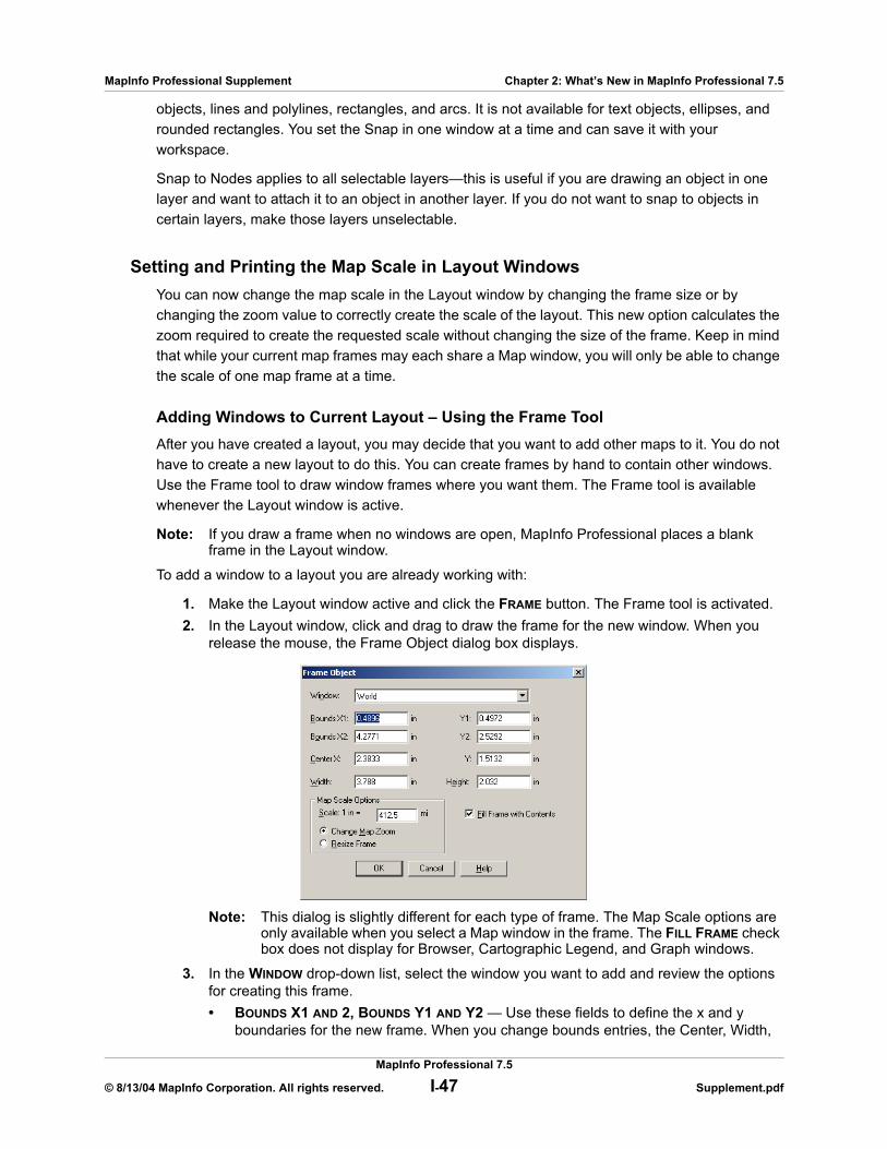
MapInfo Professional Supplement Chapter 2: What’s New in MapInfo Professional 7.5
objects, lines and polylines, rectangles, and arcs. It is not available for text objects, ellipses, and rounded rectangles. You set the Snap in one window at a time and can save it with your workspace.
Snap to Nodes applies to all selectable layers—this is useful if you are drawing an object in one layer and want to attach it to an object in another layer. If you do not want to snap to objects in certain layers, make those layers unselectable.
Setting and Printing the Map Scale in Layout WindowsYou can now change the map scale in the Layout window by changing the frame size or by changing the zoom value to correctly create the scale of the layout. This new option calculates the zoom required to create the requested scale without changing the size of the frame. Keep in mind that while your current map frames may each share a Map window, you will only be able to change the scale of one map frame at a time.
Adding Windows to Current Layout – Using the Frame Tool After you have created a layout, you may decide that you want to add other maps to it. You do not have to create a new layout to do this. You can create frames by hand to contain other windows. Use the Frame tool to draw window frames where you want them. The Frame tool is available whenever the Layout window is active.
Note: If you draw a frame when no windows are open, MapInfo Professional places a blank frame in the Layout window.
To add a window to a layout you are already working with:
1. Make the Layout window active and click the FRAME button. The Frame tool is activated. 2. In the Layout window, click and drag to draw the frame for the new window. When you
release the mouse, the Frame Object dialog box displays.
Note: This dialog is slightly different for each type of frame. The Map Scale options are only available when you select a Map window in the frame. The FILL FRAME check box does not display for Browser, Cartographic Legend, and Graph windows.
3. In the WINDOW drop-down list, select the window you want to add and review the options for creating this frame.• BOUNDS X1 AND 2, BOUNDS Y1 AND Y2 — Use these fields to define the x and y
boundaries for the new frame. When you change bounds entries, the Center, Width,
MapInfo Professional 7.5
© 8/13/04 MapInfo Corporation. All rights reserved. I-47 Supplement.pdf
MapInfo Professional Supplement Chapter 2: What’s New in MapInfo Professional 7.5
and Height entries change accordingly. When you change the bounds entries, the MAP SCALE changes as well.
• CENTER X, Y — Use these fields to define and adjust the center point of your new frame.
Note: When you make a change to the CENTER X or Y entries, the WIDTH and HEIGHT bounds do not change.
• WIDTH, HEIGHT — Use these fields to define and adjust the width and height of the new frame.
• CHANGE MAP ZOOM — Click this radio button to implement the correct map scale without changing the size of the frame. This option changes the zoom of the actual Map window so that the Layout frame is in the correct scale. This option is selected by default. Type the scale you want within this frame in the Scale. The units are set by the Paper Unit setting in the System Preferences dialog box. For example:Map Scale = Scale field entry x (Frame width / Map window width)
Note: Changing the map scale with this option will not change the values in the Bounds fields or the Width and Height fields because there is no change to the size of the frame, only the look of the map within the frame. To undo the change to the map zoom, return to the Map window and click PREVIOUS VIEW.
4. Select one of these options:• RESIZE FRAME — Click this radio button to change the size of the frame based on the
data you enter into the Scale field. When you change this entry, the bounds, Center, Width, and Height entries change accordingly.
• FILL FRAME WITH CONTENTS — Click this check box to display as much of the Map window as fits in the frame. When you do not select this button, the frame may be only partially filled but it will have the same contents as the window it contains.
5. Click OK to display the new frame in the Layout frame.
Note: When you click the CHANGE MAP ZOOM or RESIZE FRAME radio button, you set your selection as the default for the rest of the session. If you change it during the session, the change becomes the default.
Large CrosshairsWe have added a large crosshairs feature. You can use these crosshairs that extend vertically and horizontally to the length and width of the Map window to show the relative position of objects and map features in your Map window. You toggle the Large Crosshairs by clicking C in the Map and Layout windows. The Large Crosshairs stay on for the duration of the session, unless you turn them off.
Custom Symbol EnhancementsWe have added enhancements which significantly improve the implementation of custom symbols. We have:
• Increased the bitmap file size from 128K to a virtually unlimited file size • Increased the color depth of the bitmaps from 8bit maximum to a 24bit color maximum.• Increased maximum symbol point size to 240 points and increased maximum label offset
to 200 points (to support large custom symbols in maps and legends). • Added a new “Display at Actual Size” option for all custom symbols, so you can display
the symbol in its actual dimensions to see if it is appropriate for your map.
MapInfo Professional 7.5
© 8/13/04 MapInfo Corporation. All rights reserved. I-48 Supplement.pdf
MapInfo Professional Supplement Chapter 2: What’s New in MapInfo Professional 7.5
You can now:
• Create bitmaps in rectangular shapes as well as squares• Save more custom bitmap symbols than ever — you used to be limited to 256 symbols but
MapInfo Professional can now handle 32,767.
Working with Custom SymbolsYou can create and use your own custom bitmaps as symbols in MapInfo Professional. To access these custom symbols, place them in the CUSTSYMB directory and select them from the Custom Symbols option in the Font list of the Symbol Style dialog box (OPTIONS > SYMBOL STYLE). All of the custom symbols in MapInfo Professional are stored in the CUSTSYMB directory. If you cannot find this directory, there are a couple of places you could check. The location of this file depends largely on the administration of your computer, the version of MapInfo Professional you use, and the location of your installation directory.
Usually, this directory is located in Program Files\MapInfo\Professional\ (or one of it’s subdirectories) or in \Documents and Settings\user’s login directory\Applications Data\MapInfo\MapInfo\version number\. If you cannot find this directory, click START and SEARCH and search for \CUSTSYMB on your system.
Note: If you add custom symbols while you are working in MapInfo Professional, open the Symbol Style dialog box and click the RELOAD button to ensure that the new symbol(s) you have added display. Otherwise, you have to exit MapInfo Professional and re-enter it to get the new symbols to display in the Custom Symbols list.
When you change the style of a custom symbol, the Effects options in the Symbol Style dialog box change. You can either show a background or apply a color.
• SHOW BACKGROUND displays the custom symbol with the background color with which it was created.
• APPLY COLOR replaces all non-white pixels with a color you choose from the color palette.• DISPLAY AT ACTUAL SIZE shows the symbol at its actual size.
When you are creating extended custom symbols we recommend you check the Show Background check box if you do not require transparency. This setting improves performance significantly during exporting and Drag and Drop operations.
MapInfo Professional ships with custom symbols that you can use to enhance your maps. Here is a list of the custom symbols we provide.
Title Image File Size Color Depth
AMBU-64.BMP 13 KB 24-bit
BANK-64.BMP 13 KB 24-bit
MapInfo Professional 7.5
© 8/13/04 MapInfo Corporation. All rights reserved. I-49 Supplement.pdf
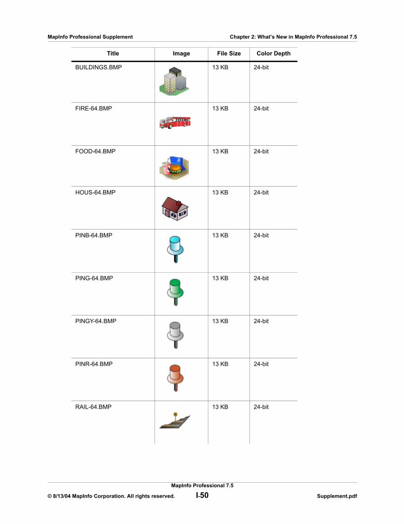
MapInfo Professional Supplement Chapter 2: What’s New in MapInfo Professional 7.5
BUILDINGS.BMP 13 KB 24-bit
FIRE-64.BMP 13 KB 24-bit
FOOD-64.BMP 13 KB 24-bit
HOUS-64.BMP 13 KB 24-bit
PINB-64.BMP 13 KB 24-bit
PING-64.BMP 13 KB 24-bit
PINGY-64.BMP 13 KB 24-bit
PINR-64.BMP 13 KB 24-bit
RAIL-64.BMP 13 KB 24-bit
Title Image File Size Color Depth
MapInfo Professional 7.5
© 8/13/04 MapInfo Corporation. All rights reserved. I-50 Supplement.pdf

MapInfo Professional Supplement Chapter 2: What’s New in MapInfo Professional 7.5
Understanding the Custom Symbol TypesThere are two types of custom symbols: custom symbols and extended custom symbols. The difference in these two types depends upon the complexity of the bitmap images. Files that are equal to or larger than 128K and/or have greater than 8 bit color are considered to be extended custom symbols. You need to know the distinction between these two types of custom symbols because the options for the extended custom symbols are slightly different from the custom symbols.
Understanding the Custom Symbol Sizes, Shape, and Color RulesYou can create various sized and shaped bitmaps for use as custom symbols. As a general rule, smaller symbols look better at smaller font sizes because they won’t need to be stretched. Larger symbols look better at larger font sizes because they have more pixels and more detail. Here are some rules and tips that govern custom symbols:
• You can select the point size for custom bitmaps from 9 to 240 pt.• You can display the custom bitmap image at actual size.• There is no a file size limit for custom bitmaps (other than what is required by your raster
engine and the amount of memory you have). • Extended custom symbols can be either rectangular or square in shape.• Extended custom symbols usually have their own complex color pattern (which is what
makes them extended) so the APPLY COLOR option is disabled.• MapInfo Professional supports up to 24bit color bitmaps.
When you are dealing with very large bitmaps, there are a couple of special rules to keep mind:
• Some users have reported panning problems associated with very large symbols. When you create a symbol that is larger than 36 points, the symbol may not completely redraw as you pan across your map. To alleviate this problem, go to the system registry and add or change your MBRExtraPoints registry entry.
• There are times when the custom symbol you are trying to display is too large for the Sample area.
RED-CAR.BMP 13 KB 24-bit
TRUC-64.BMP 13 KB 24-bit
Title Image File Size Color Depth
MapInfo Professional 7.5
© 8/13/04 MapInfo Corporation. All rights reserved. I-51 Supplement.pdf
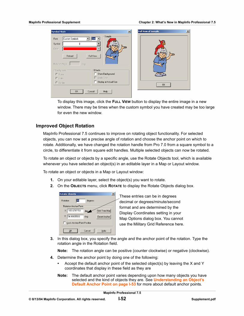
MapInfo Professional Supplement Chapter 2: What’s New in MapInfo Professional 7.5
To display this image, click the FULL VIEW button to display the entire image in a new window. There may be times when the custom symbol you have created may be too large for even the new window.
Improved Object RotationMapInfo Professional 7.5 continues to improve on rotating object functionality. For selected objects, you can now set a precise angle of rotation and choose the anchor point on which to rotate. Additionally, we have changed the rotation handle from Pro 7.0 from a square symbol to a circle, to differentiate it from square edit handles. Multiple selected objects can now be rotated.
To rotate an object or objects by a specific angle, use the Rotate Objects tool, which is available whenever you have selected an object(s) in an editable layer in a Map or Layout window.
To rotate an object or objects in a Map or Layout window:
1. On your editable layer, select the object(s) you want to rotate.2. On the OBJECTS menu, click ROTATE to display the Rotate Objects dialog box.
3. In this dialog box, you specify the angle and the anchor point of the rotation. Type the rotation angle in the Rotation field.
Note: The rotation angle can be positive (counter clockwise) or negative (clockwise).
4. Determine the anchor point by doing one of the following:• Accept the default anchor point of the selected object(s) by leaving the X and Y
coordinates that display in these field as they are
Note: The default anchor point varies depending upon how many objects you have selected and the kind of objects they are. See Understanding an Object’s Default Anchor Point on page I-53 for more about default anchor points.
These entries can be in degrees decimal or degrees/minute/second format and are determined by the Display Coordinates setting in your Map Options dialog box. You cannot use the Military Grid Reference here.
MapInfo Professional 7.5
© 8/13/04 MapInfo Corporation. All rights reserved. I-52 Supplement.pdf
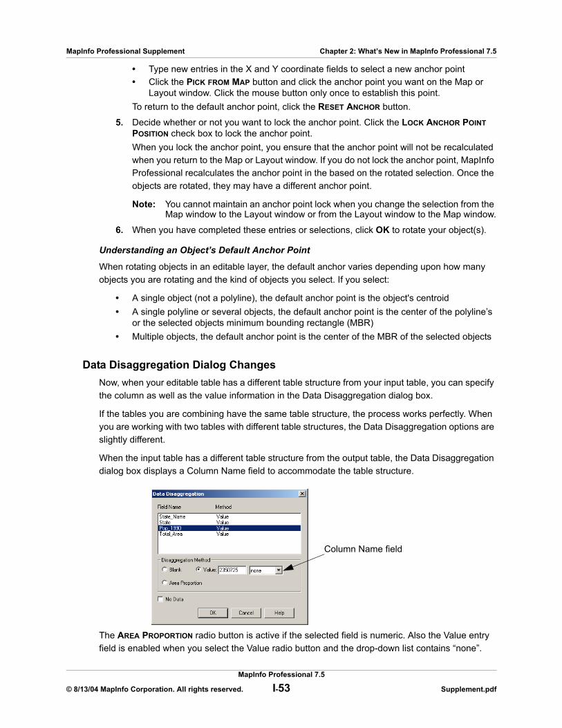
MapInfo Professional Supplement Chapter 2: What’s New in MapInfo Professional 7.5
• Type new entries in the X and Y coordinate fields to select a new anchor point• Click the PICK FROM MAP button and click the anchor point you want on the Map or
Layout window. Click the mouse button only once to establish this point.To return to the default anchor point, click the RESET ANCHOR button.
5. Decide whether or not you want to lock the anchor point. Click the LOCK ANCHOR POINT POSITION check box to lock the anchor point. When you lock the anchor point, you ensure that the anchor point will not be recalculated when you return to the Map or Layout window. If you do not lock the anchor point, MapInfo Professional recalculates the anchor point in the based on the rotated selection. Once the objects are rotated, they may have a different anchor point.
Note: You cannot maintain an anchor point lock when you change the selection from the Map window to the Layout window or from the Layout window to the Map window.
6. When you have completed these entries or selections, click OK to rotate your object(s).
Understanding an Object’s Default Anchor Point
When rotating objects in an editable layer, the default anchor varies depending upon how many objects you are rotating and the kind of objects you select. If you select:
• A single object (not a polyline), the default anchor point is the object's centroid• A single polyline or several objects, the default anchor point is the center of the polyline’s
or the selected objects minimum bounding rectangle (MBR)• Multiple objects, the default anchor point is the center of the MBR of the selected objects
Data Disaggregation Dialog ChangesNow, when your editable table has a different table structure from your input table, you can specify the column as well as the value information in the Data Disaggregation dialog box.
If the tables you are combining have the same table structure, the process works perfectly. When you are working with two tables with different table structures, the Data Disaggregation options are slightly different.
When the input table has a different table structure from the output table, the Data Disaggregation dialog box displays a Column Name field to accommodate the table structure.
The AREA PROPORTION radio button is active if the selected field is numeric. Also the Value entry field is enabled when you select the Value radio button and the drop-down list contains “none”.
Column Name field
MapInfo Professional 7.5
© 8/13/04 MapInfo Corporation. All rights reserved. I-53 Supplement.pdf

MapInfo Professional Supplement Chapter 2: What’s New in MapInfo Professional 7.5
Dot Density Theme EnhancementsWhen you create a dot density map, the size of the dots have been changed. Large dots are now 3 screen pixels wide and small pixels are 2 pixels wide. This change is evident in the Customize Dot Density Settings dialog box.
Object Clean Gaps ModificationWe have changed the way we handle gaps in polygons. When there is a gap between two adjacent regions, MapInfo Professional will add the gap to the region with the longest shared edge.
The CLEAN command available from the OBJECTS menu enables you to remove any self-intersections in your region data and optionally alter region data to remove overlaps and/or gaps. CLEAN is available whenever there are objects selected, and the table that the objects are in is editable.
Note: All of the objects selected must be closed objects (e.g., regions, rectangles, rounded rectangles or ellipses).
To use the Clean command:
1. Open any Map window that includes a region layer.2. Make the region layer editable if it is not already (on the MAP menu click LAYER CONTROL).3. Select the objects that you want to clean. Ideally, all the objects in the table would be
selected. 4. On the OBJECTS menu, click CLEAN. The Clean Objects dialog box displays.
5. Click the ENABLE OVERLAP REMOVAL check box to remove any overlapping areas. The area of overlap will be retained in the region that has the largest area; the overlap will be removed from any other overlapping regions.
6. Click the ENABLE GAP REMOVAL check box to remove any gaps between regions, where the area of the gap is less than the area provided. The area of the gap will be added to the adjacent region with the longest shared edge. Specify a maximum gap area and the area units you want to use.
7. Click OK.
Setting Map Bounds for DBMS TablesIn this release you can specify the bounds for a RDBMS table when you make the table mappable for live access databases. By allowing you set the map bounds, you can better control the visibility of your data, which is particularly important when downloading large tables. Also in this release,
MapInfo Professional 7.5
© 8/13/04 MapInfo Corporation. All rights reserved. I-54 Supplement.pdf
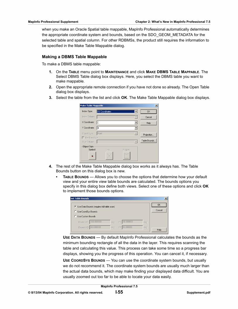
MapInfo Professional Supplement Chapter 2: What’s New in MapInfo Professional 7.5
when you make an Oracle Spatial table mappable, MapInfo Professional automatically determines the appropriate coordinate system and bounds, based on the SDO_GEOM_METADATA for the selected table and spatial column. For other RDBMSs, the product still requires the information to be specified in the Make Table Mappable dialog.
Making a DBMS Table MappableTo make a DBMS table mappable:
1. On the TABLE menu point to MAINTENANCE and click MAKE DBMS TABLE MAPPABLE. The Select DBMS Table dialog box displays. Here, you select the DBMS table you want to make mappable.
2. Open the appropriate remote connection if you have not done so already. The Open Table dialog box displays.
3. Select the table from the list and click OK. The Make Table Mappable dialog box displays.
4. The rest of the Make Table Mappable dialog box works as it always has. The Table Bounds button on this dialog box is new.• TABLE BOUNDS — Allows you to choose the options that determine how your default
view and your entire view table bounds are calculated. The bounds options you specify in this dialog box define both views. Select one of these options and click OK to implement those bounds options.
USE DATA BOUNDS — By default MapInfo Professional calculates the bounds as the minimum bounding rectangle of all the data in the layer. This requires scanning the table and calculating this value. This process can take some time so a progress bar displays, showing you the progress of this operation. You can cancel it, if necessary.
USE COORDSYS BOUNDS — You can use the coordinate system bounds, but usually we do not recommend it. The coordinate system bounds are usually much larger than the actual data bounds, which may make finding your displayed data difficult. You are usually zoomed out too far to be able to locate your data easily.
MapInfo Professional 7.5
© 8/13/04 MapInfo Corporation. All rights reserved. I-55 Supplement.pdf
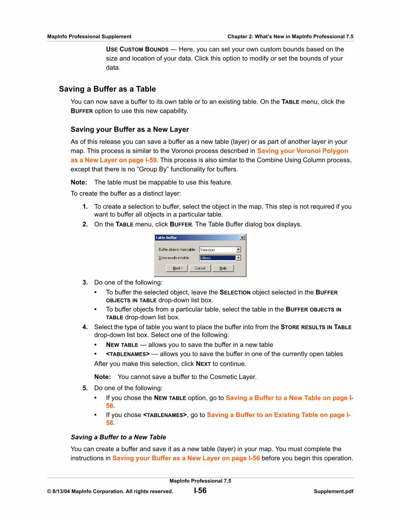
MapInfo Professional Supplement Chapter 2: What’s New in MapInfo Professional 7.5
USE CUSTOM BOUNDS — Here, you can set your own custom bounds based on the size and location of your data. Click this option to modify or set the bounds of your data.
Saving a Buffer as a TableYou can now save a buffer to its own table or to an existing table. On the TABLE menu, click the BUFFER option to use this new capability.
Saving your Buffer as a New LayerAs of this release you can save a buffer as a new table (layer) or as part of another layer in your map. This process is similar to the Voronoi process described in Saving your Voronoi Polygon as a New Layer on page I-59. This process is also similar to the Combine Using Column process, except that there is no “Group By” functionality for buffers.
Note: The table must be mappable to use this feature.
To create the buffer as a distinct layer:
1. To create a selection to buffer, select the object in the map. This step is not required if you want to buffer all objects in a particular table.
2. On the TABLE menu, click BUFFER. The Table Buffer dialog box displays.
3. Do one of the following:• To buffer the selected object, leave the SELECTION object selected in the BUFFER
OBJECTS IN TABLE drop-down list box.• To buffer objects from a particular table, select the table in the BUFFER OBJECTS IN
TABLE drop-down list box.4. Select the type of table you want to place the buffer into from the STORE RESULTS IN TABLE
drop-down list box. Select one of the following:• NEW TABLE — allows you to save the buffer in a new table• <TABLENAMES> — allows you to save the buffer in one of the currently open tablesAfter you make this selection, click NEXT to continue.
Note: You cannot save a buffer to the Cosmetic Layer.
5. Do one of the following:• If you chose the NEW TABLE option, go to Saving a Buffer to a New Table on page I-
56.• If you chose <TABLENAMES>, go to Saving a Buffer to an Existing Table on page I-
58.
Saving a Buffer to a New Table
You can create a buffer and save it as a new table (layer) in your map. You must complete the instructions in Saving your Buffer as a New Layer on page I-56 before you begin this operation.
MapInfo Professional 7.5
© 8/13/04 MapInfo Corporation. All rights reserved. I-56 Supplement.pdf
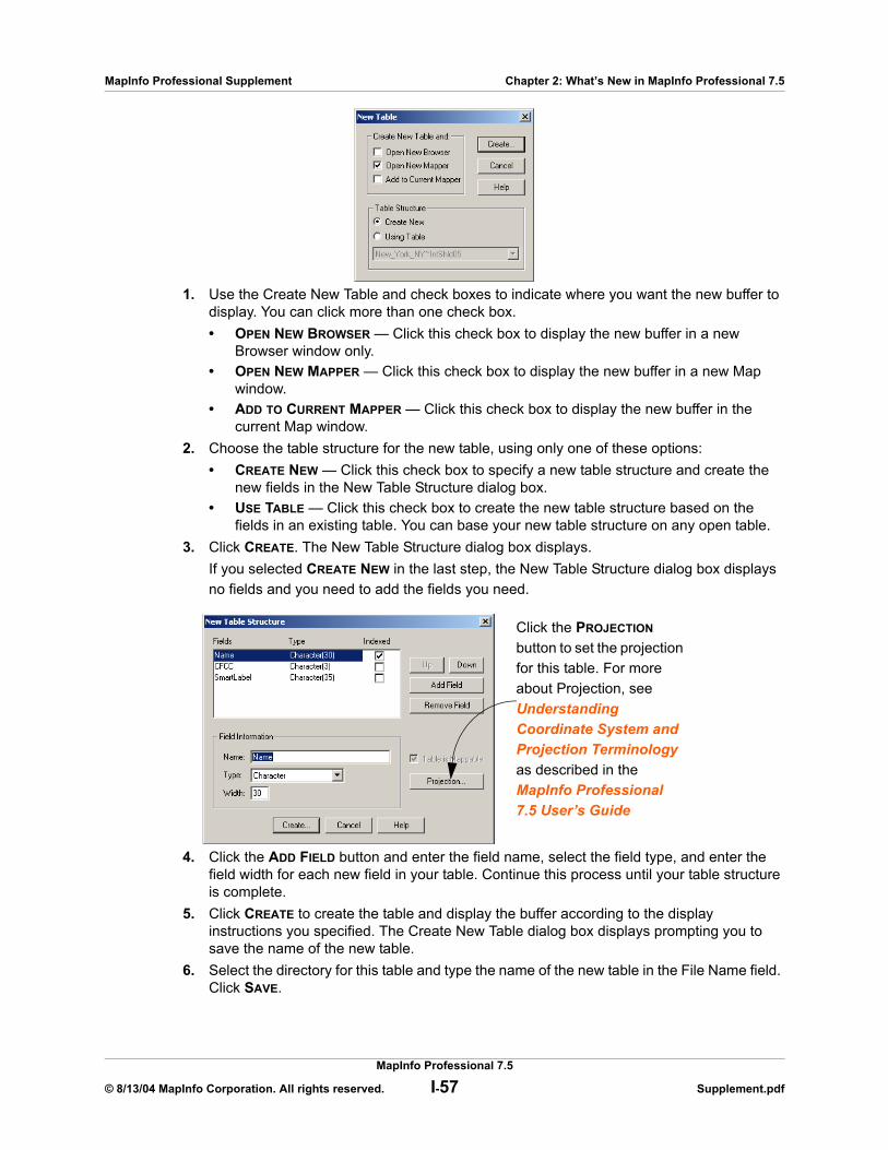
MapInfo Professional Supplement Chapter 2: What’s New in MapInfo Professional 7.5
1. Use the Create New Table and check boxes to indicate where you want the new buffer to display. You can click more than one check box.• OPEN NEW BROWSER — Click this check box to display the new buffer in a new
Browser window only.• OPEN NEW MAPPER — Click this check box to display the new buffer in a new Map
window.• ADD TO CURRENT MAPPER — Click this check box to display the new buffer in the
current Map window.2. Choose the table structure for the new table, using only one of these options:
• CREATE NEW — Click this check box to specify a new table structure and create the new fields in the New Table Structure dialog box.
• USE TABLE — Click this check box to create the new table structure based on the fields in an existing table. You can base your new table structure on any open table.
3. Click CREATE. The New Table Structure dialog box displays. If you selected CREATE NEW in the last step, the New Table Structure dialog box displays no fields and you need to add the fields you need.
4. Click the ADD FIELD button and enter the field name, select the field type, and enter the field width for each new field in your table. Continue this process until your table structure is complete.
5. Click CREATE to create the table and display the buffer according to the display instructions you specified. The Create New Table dialog box displays prompting you to save the name of the new table.
6. Select the directory for this table and type the name of the new table in the File Name field. Click SAVE.
Click the PROJECTION button to set the projection for this table. For more about Projection, see Understanding Coordinate System and Projection Terminology as described in the MapInfo Professional 7.5 User’s Guide
MapInfo Professional 7.5
© 8/13/04 MapInfo Corporation. All rights reserved. I-57 Supplement.pdf
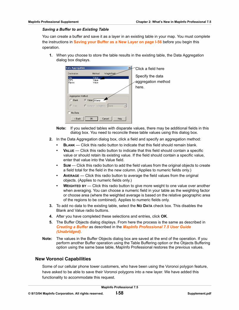
MapInfo Professional Supplement Chapter 2: What’s New in MapInfo Professional 7.5
Saving a Buffer to an Existing Table
You can create a buffer and save it as a layer in an existing table in your map. You must complete the instructions in Saving your Buffer as a New Layer on page I-56 before you begin this operation.
1. When you choose to store the table results in the existing table, the Data Aggregation dialog box displays.
Note: If you selected tables with disparate values, there may be additional fields in this dialog box. You need to reconcile these table values using this dialog box.
2. In the Data Aggregation dialog box, click a field and specify an aggregation method:• BLANK — Click this radio button to indicate that this field should remain blank.• VALUE — Click this radio button to indicate that this field should contain a specific
value or should retain its existing value. If the field should contain a specific value, enter that value into the Value field.
• SUM — Click this radio button to add the field values from the original objects to create a field total for the field in the new column. (Applies to numeric fields only.)
• AVERAGE — Click this radio button to average the field values from the original objects. (Applies to numeric fields only.)
• WEIGHTED BY — Click this radio button to give more weight to one value over another when averaging. You can choose a numeric field in your table as the weighting factor or choose area (where the weighted average is based on the relative geographic area of the regions to be combined). Applies to numeric fields only.
3. To add no data to the existing table, select the NO DATA check box. This disables the Blank and Value radio buttons.
4. After you have completed these selections and entries, click OK.5. The Buffer Objects dialog displays. From here the process is the same as described in
Creating a Buffer as described in the MapInfo Professional 7.5 User Guide (Unabridged).
Note: The values in the Buffer Objects dialog box are saved at the end of the operation. If you perform another Buffer operation using the Table Buffering option or the Objects Buffering option using the same base table, MapInfo Professional restores the previous values.
New Voronoi CapabilitiesSome of our cellular phone tower customers, who have been using the Voronoi polygon feature, have asked to be able to save their Voronoi polygons into a new layer. We have added this functionality to accommodate this request.
Click a field here
Specify the data aggregation method here.
MapInfo Professional 7.5
© 8/13/04 MapInfo Corporation. All rights reserved. I-58 Supplement.pdf

MapInfo Professional Supplement Chapter 2: What’s New in MapInfo Professional 7.5
Saving your Voronoi Polygon as a New LayerThe Table Voronoi operation provides an another way to create Voronoi polygons from a table and provides a mechanism to place the results into a new table. This process is not directly available using the Objects Voronoi operation.
Note: You cannot place Voronoi polygons in the Cosmetic Layer.
To set up a Voronoi polygon in new table or in an existing table:
1. Open and display the table for which you want to create Voronoi polygons.
Note: If you want to use a selection to create the Voronoi polygon, hold down the SHIFT key and select the points you want. This is not required. If you do not make a selection at this point, MapInfo Professional will use all of the points on the selected layer to create the polygon.
2. To create a boundary for the Voronoi polygon layer you are creating, use the Target Object feature described in Overlaying Nodes as described in the MapInfo Professional 7.5 User Guide (Unabridged). This is not required.
3. On the TABLE menu, click VORONOI. The Table Voronoi dialog box displays.
4. Select the layer you want to create the Voronoi polygon with in the PERFORM VORONOI USING OBJECTS FROM TABLE drop-down list. If you selected points you want to use to create this polygon, choose the “Selection” entry in this list.
5. Select the table type for the results of the Voronoi polygon from the Store results in table drop-down list:• NEW TABLE — allows you to save the Voronoi polygon in a new table• <TABLENAMES> — allows you to save the Voronoi polygon into one of the currently
open tables that contain point objects6. After you make this selection, click NEXT to continue. Do one of the following:
• If you selected the NEW TABLE option, go to Save the Voronoi Polygon to a New Table on page I-59.
• If you selected the <TABLENAMES> option, go to Save the Voronoi Polygon to an Existing Table on page I-61.
Save the Voronoi Polygon to a New Table
To save the Voronoi Polygon to a new table:
1. In the New Table dialog box, follow these directions:
MapInfo Professional 7.5
© 8/13/04 MapInfo Corporation. All rights reserved. I-59 Supplement.pdf
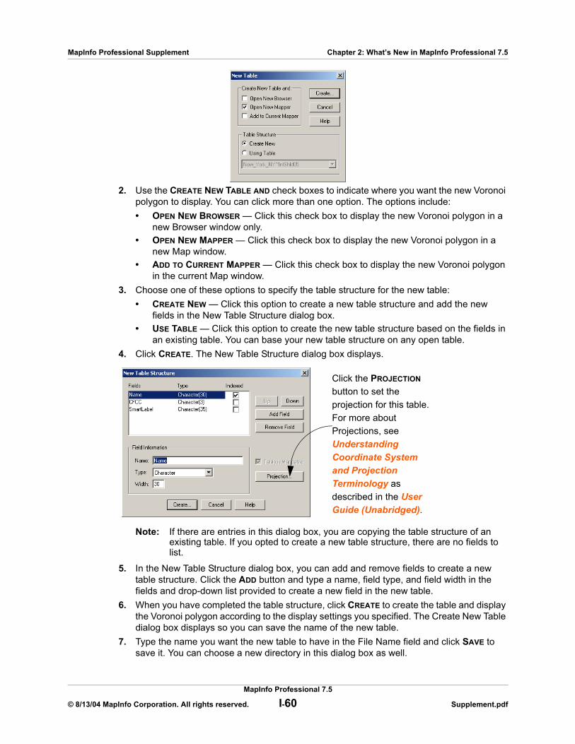
MapInfo Professional Supplement Chapter 2: What’s New in MapInfo Professional 7.5
2. Use the CREATE NEW TABLE AND check boxes to indicate where you want the new Voronoi polygon to display. You can click more than one option. The options include:• OPEN NEW BROWSER — Click this check box to display the new Voronoi polygon in a
new Browser window only.• OPEN NEW MAPPER — Click this check box to display the new Voronoi polygon in a
new Map window.• ADD TO CURRENT MAPPER — Click this check box to display the new Voronoi polygon
in the current Map window.3. Choose one of these options to specify the table structure for the new table:
• CREATE NEW — Click this option to create a new table structure and add the new fields in the New Table Structure dialog box.
• USE TABLE — Click this option to create the new table structure based on the fields in an existing table. You can base your new table structure on any open table.
4. Click CREATE. The New Table Structure dialog box displays.
Note: If there are entries in this dialog box, you are copying the table structure of an existing table. If you opted to create a new table structure, there are no fields to list.
5. In the New Table Structure dialog box, you can add and remove fields to create a new table structure. Click the ADD button and type a name, field type, and field width in the fields and drop-down list provided to create a new field in the new table.
6. When you have completed the table structure, click CREATE to create the table and display the Voronoi polygon according to the display settings you specified. The Create New Table dialog box displays so you can save the name of the new table.
7. Type the name you want the new table to have in the File Name field and click SAVE to save it. You can choose a new directory in this dialog box as well.
Click the PROJECTION button to set the projection for this table. For more about Projections, see Understanding Coordinate System and Projection Terminology as described in the User Guide (Unabridged).
MapInfo Professional 7.5
© 8/13/04 MapInfo Corporation. All rights reserved. I-60 Supplement.pdf
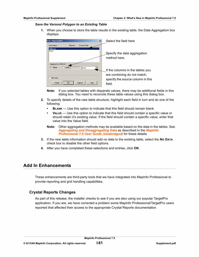
MapInfo Professional Supplement Chapter 2: What’s New in MapInfo Professional 7.5
Save the Voronoi Polygon to an Existing Table
1. When you choose to store the table results in the existing table, the Data Aggregation box displays.
Note: If you selected tables with disparate values, there may be additional fields in this dialog box. You need to reconcile these table values using this dialog box.
2. To specify details of the new table structure, highlight each field in turn and do one of the following:• BLANK — Use this option to indicate that this field should remain blank.• VALUE — Use this option to indicate that this field should contain a specific value or
should retain it’s existing value. If the field should contain a specific value, enter that value into the Value field.
Note: Other aggregation methods may be available based on the data in the tables. See Aggregating and Disaggregating Data as described in the MapInfo Professional 7.5 User Guide (Unabridged) for these details.
3. If the new table information should add no data to the existing table, select the NO DATA check box to disable the other field options.
4. After you have completed these selections and entries, click OK.
Add In Enhancements
These enhancements are third-party tools that we have integrated into MapInfo Professional to provide reporting and grid handling capabilities.
Crystal Reports ChangesAs part of this release, the installer checks to see if you are also using our popular TargetPro application. If you are, we have corrected a problem some MapInfo Professional/TargetPro users reported that affected their access to the appropriate Crystal Reports documentation.
Select the field here
Specify the data aggregation method here.
If the columns in the tables you are combining do not match, specify the source column in this field.
MapInfo Professional 7.5
© 8/13/04 MapInfo Corporation. All rights reserved. I-61 Supplement.pdf
MapInfo Professional Supplement Chapter 2: What’s New in MapInfo Professional 7.5
Vertical Mapper IntegrationMapInfo Corporation has purchased Vertical Mapper, a raster-based tool for performing spatial queries and geostatistical analysis on grid layers. Vertical Mapper has 3D features and analysis tools including:
• Import tools for grid-based formats• Grid layer creation and reclassification (Square Area and Kernel Smoothing)• Grid layer reprojection• Grid layer resizing, splicing, and trimming • Multiple interpolation routines (Triangulation, IDW, Natural Neighbor, Rectangular, Kriging,
and Custom Point Estimation)• Cross-Sections• Grid Contouring• 3D Viewing and Analysis• Point-To-Point Visibility• View Shed Analysis• Data Aggregation Tools• Spatial Correlation Tools• Tools for converting grid layers to vector layers• Tools for converting vector layers to grid layers
This is an excellent tool, particularly for customers who use grid layers for elevation studies or need to show or demonstrate “vertical” information. 1Vertical Mapper does not ship with MapInfo Professional automatically.
Menu Enhancements
We provide these menu enhancements to make it easier to use the Window menu features.
Window Menu ChangesThere are several changes to the Window menu in MapInfo Professional. We have added a check mark to show the active window as shown in the next figure.
MapInfo Professional 7.5
© 8/13/04 MapInfo Corporation. All rights reserved. I-62 Supplement.pdf

MapInfo Professional Supplement Chapter 2: What’s New in MapInfo Professional 7.5
If there are more than nine windows open at the same time, the entry “More Windows” displays.
Note: The only way to change the order of the windows in the Window menu list is to close open windows.
Tool Enhancements
We have added tools and made changes to existing tools to help you work more efficiently.
New Tools for MapInfo Professional 7.5
Cogoline ToolThis tool, also called Create Line by Length, draws a line of a specified length and angle, which the product now saves by default to the current editable layer. If there is no editable layer, MapInfo Professional saves the line to the Cosmetic Layer, as before -- but it now sets the Cosmetic layer to be editable, so that you can select and edit the resulting lines. We have also expanded the number of units associated with the Length field to include: millimeters, centimeters, meters, kilometers, nautical miles, inches, yards, links, rods, and chains as well as feet and miles.
Register Vector ToolThis tool allows you to put control points into a vector image and reference points into a Map window and then performs an affine transformation to line them up. An affine transformation changes the relationship between the coordinate system you use to draw a map and the coordinate system you use to display it. The interface is similar to the Raster Registration tool. You might use this tool after importing an Autocad or ESRI Shape file which contains the wrong coordinate system, placing the table in the wrong geographic location.
MapInfo Professional 7.5
© 8/13/04 MapInfo Corporation. All rights reserved. I-63 Supplement.pdf
MapInfo Professional Supplement Chapter 2: What’s New in MapInfo Professional 7.5
Workspace PackagerThe Workspace Packager is a new tool that saves a copy of the current workspace and saves a copy of all data referenced by the workspace in a new location. You can use this tool to manage and update internal workspace references and update .tab files to point only to the “packaged” copies of the data. You can open the new workspace no matter where the folder has been moved or copied to, even a different computer. Add the Workspace Packager tool using the Tool Manager (available in the TOOLS menu).
Enhancements to Existing Tools in MapInfo Professional 7.5
Line Snap (Trim/Extend) Tool EnhancedUse the Line Snap tool to trim or extend a line (or a single-segment polyline) that intersects with another line in the Map window. This tool helps you make cleaner intersections when working with lines. For instructions for using this tool, click the TOOLS menu, point to LINE SNAP TOOL, and click ABOUT LINE SNAP.
Map Window Manager Tool EnhancedYou can now change the titles of the Map, Browser, Graph, Layout and Redistrict windows using the Window Manager tool. We have changed the name of the Map Window Manager to the Window Manager, since this tool no longer applies to Map windows alone. We have maintained the Set Default View option from previous versions of this tool. This option allows you to select a layer from an open map window, and make the default zoom and center settings for the layer's base table match those of the map window. The default zoom and center settings are written to the table's .map file.
Note: You cannot change the default view for a raster image table, unless it is a seamless table.
The Autoscroll option has been removed from this tool, since we now provide this functionality in the Options window.
TOC Utility UpdatedThe TOC Utility produces seamless tables from Table of Contents [TOC/THF] files (formats defined by the National Imaging and Mapping Agency (NIMA)). To improve conversion speed for large image sets, we added an option that prevents MapInfo Professional from opening a new map window for each newly-created seamless table. We have also made some internal changes to give programmers the tools they need to call functions in a separate module, TOCCore.MBO. You can use this module to batch process large numbers of TOC/THF files without having to locate each file using the GUI interface.
MapInfo Professional 7.5
© 8/13/04 MapInfo Corporation. All rights reserved. I-64 Supplement.pdf
MapInfo Professional Supplement Chapter 2: What’s New in MapInfo Professional 7.5
EasyLoader Changes
Our company is no longer providing Merant ODBC Drivers for MapInfo Professional. We have made enhancements to the EasyLoader program to perform the same role with drivers provided by the standard ODBC install. This change in drivers is handled during the MapInfo Professional installation process. To ensure that you install all of the necessary drivers for ODBC Connectivity, see Custom Workstation Installation in Chapter 1 on page I-14.
MapBasic Enhancements
There are changes to the Move and Offset functionality, the addition of Web Map Service, and the changes to the Make Table Mappable functionality that affect the MapBasic code. See New and Enhanced MapBasic Statements and Functions in Appendix C on page I-78 for details on the new statements and functions available in this release.
MapInfo Professional 7.5
© 8/13/04 MapInfo Corporation. All rights reserved. I-65 Supplement.pdf

A
Directory of MapInfo Professional ShortcutsThis Appendix contains a comprehensive list of the shortcuts available in the MapInfo Professional application. You can create custom shortcuts by editing the MAPINFOW.MNU file using a text editor.
CAUTION: Making changes to the MAPINFOW.MNU file will cause default shortcuts to stop working. Make these changes carefully and record your changes so you can change them back, if necessary.
In this Appendix:
Shortcuts for File Menu Items . . . . . . . . . . . . . . . . . . . . . . . . . . I-67Shortcuts for Edit Menu Items. . . . . . . . . . . . . . . . . . . . . . . . . . I-67Shortcut to Tools Menu Items . . . . . . . . . . . . . . . . . . . . . . . . . . I-67Shortcuts to Objects Menu Items . . . . . . . . . . . . . . . . . . . . . . . I-68Shortcuts for Query Menu Items. . . . . . . . . . . . . . . . . . . . . . . . I-68Shortcuts for Options Menu Items . . . . . . . . . . . . . . . . . . . . . . I-68Shortcuts for Map Menu Items . . . . . . . . . . . . . . . . . . . . . . . . . I-69Shortcut for Layout Menu Item . . . . . . . . . . . . . . . . . . . . . . . . . I-69Shortcuts for Windows Menu Items . . . . . . . . . . . . . . . . . . . . . I-69Shortcuts by Keystroke . . . . . . . . . . . . . . . . . . . . . . . . . . . . . . . I-70
MapInfo Professional Supplement Chapter A: Directory of MapInfo Professional Shortcuts
Shortcuts for File Menu Items
Shortcuts for Edit Menu Items
Shortcut to Tools Menu Items
Menu Item Keystrokes
File > Open... CTRL+O
File > Save Table... CTRL+S
File > Save Workspace CTRL+K
File > Print... CTRL+P
File > Exit ALT+F4
Menu Item Keystrokes
Edit > Undo CTRL+Z
Edit > Cut CTRL+X
Edit > Copy CTRL+C
Edit > Paste CTRL+V
Edit > Clear DEL
Edit > Reshape CTRL+R
Edit > New Row CTRL+E
Edit > Get Info F7
Menu Item Keystrokes
Tools > Run MapBasic Program CTRL+U
MapInfo Professional 7.5
© 8/13/04 MapInfo Corporation. All rights reserved. I-67 Supplement.pdf
MapInfo Professional Supplement Chapter A: Directory of MapInfo Professional Shortcuts
Shortcuts to Objects Menu Items
Shortcuts for Query Menu Items
Shortcuts for Options Menu Items
Menu Item Keystrokes
Objects > Set Target CTRL+T
Objects > Clear Target CTRL+DELETE
Menu Item Keystrokes
Query > Unselect All CTRL+W
Query > Find... CTRL+F
Query > Find Selection CTRL+G
Menu Item Keystrokes
Options > Line Style SHIFT+F8
Options > Region Style... CTRL+F8
Options > Symbol Style ALT+F8
Options > Text Style F8
MapInfo Professional 7.5
© 8/13/04 MapInfo Corporation. All rights reserved. I-68 Supplement.pdf
MapInfo Professional Supplement Chapter A: Directory of MapInfo Professional Shortcuts
Shortcuts for Map Menu Items
Shortcut for Layout Menu Item
Shortcuts for Windows Menu Items
Menu Item Keystrokes
Map > Layer Control... CTRL+L
Map > Create 3D Map F10
Map > Create Prism Map F11
Map > Create Thematic Map F9
Map > Modify Thematic Map ALT+F9
Map > Previous View ALT+LEFT ARROW
Menu Item Keystrokes
Layout > Previous View ALT+LEFT ARROW
Menu Item Keystrokes
Window > New Browser F2
Window > New Mapper F3
Window > New Grapher F4
Window > New Layout F5
Window > Redraw Window CTRL+D
Window > Tile Windows SHIFT+F4
Window > Cascade Windows SHIFT+F5
MapInfo Professional 7.5
© 8/13/04 MapInfo Corporation. All rights reserved. I-69 Supplement.pdf
MapInfo Professional Supplement Chapter A: Directory of MapInfo Professional Shortcuts
Shortcuts by Keystroke
Menu Items Keystrokes
File > Exit ALT+F4
Options > Symbol Style ALT+F8
Map > Modify Thematic Map ALT+F9
Map > Previous View and Layout > Previous View
ALT+LEFT ARROW
File > Copy CTRL+C
Window > Redraw Window CTRL+D
File > New Row CTRL+E
Query > Find... CTRL+F
Options > Region Style... CTRL+F8
Query > Find Selection CTRL+G
Query > Invert Selection CTRL+I
File > Save Workspace CTRL+K
Map > Layer Control... CTRL+L
File > New Table... CTRL+N
File > Open... CTRL+O
File > Print... CTRL+P
File > Reshape CTRL+R
File > Save Table... CTRL+S
Objects > Set Target CTRL+T
Tools > Run MapBasic Program CTRL+U
File > Paste CTRL+V
Query > Unselect All CTRL+W
File > Cut CTRL+X
File > Undo CTRL+Z
Objects > Clear Target CTRL+DELETE
Window > New Browser F2
Window > New Mapper F3
MapInfo Professional 7.5
© 8/13/04 MapInfo Corporation. All rights reserved. I-70 Supplement.pdf
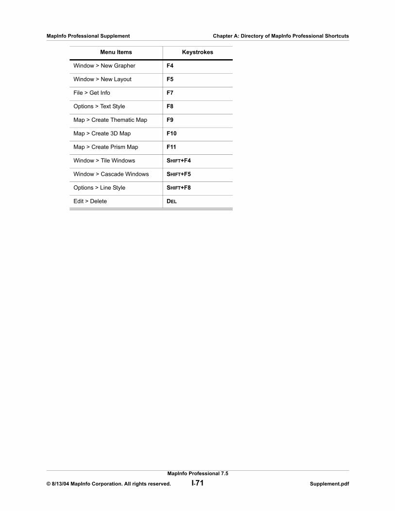
MapInfo Professional Supplement Chapter A: Directory of MapInfo Professional Shortcuts
Window > New Grapher F4
Window > New Layout F5
File > Get Info F7
Options > Text Style F8
Map > Create Thematic Map F9
Map > Create 3D Map F10
Map > Create Prism Map F11
Window > Tile Windows SHIFT+F4
Window > Cascade Windows SHIFT+F5
Options > Line Style SHIFT+F8
Edit > Delete DEL
Menu Items Keystrokes
MapInfo Professional 7.5
© 8/13/04 MapInfo Corporation. All rights reserved. I-71 Supplement.pdf

B
Fill Patterns Used in MapInfo ProfessionalIn the Region Style dialog box, you have the option of selecting fill patterns for regions. This appendix shows the fill patterns and their ID numbers.
Sections in this Appendix:
Fill Pattern Table . . . . . . . . . . . . . . . . . . . . . . . . . . . . . . . . . . . . . I-73New Fill Patterns (Added in This Release). . . . . . . . . . . . . . . . I-74
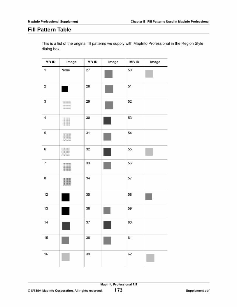
MapInfo Professional Supplement Chapter B: Fill Patterns Used in MapInfo Professional
Fill Pattern Table
This is a list of the original fill patterns we supply with MapInfo Professional in the Region Style dialog box.
MB ID Image MB ID Image MB ID Image
1 None 27 50
2 28 51
3 29 52
4 30 53
5 31 54
6 32 55
7 33 56
8 34 57
12 35 58
13 36 59
14 37 60
15 38 61
16 39 62
MapInfo Professional 7.5
© 8/13/04 MapInfo Corporation. All rights reserved. I-73 Supplement.pdf
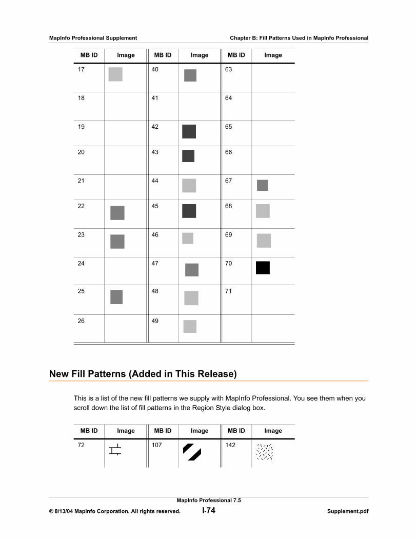
MapInfo Professional Supplement Chapter B: Fill Patterns Used in MapInfo Professional
New Fill Patterns (Added in This Release)
This is a list of the new fill patterns we supply with MapInfo Professional. You see them when you scroll down the list of fill patterns in the Region Style dialog box.
17 40 63
18 41 64
19 42 65
20 43 66
21 44 67
22 45 68
23 46 69
24 47 70
25 48 71
26 49
MB ID Image MB ID Image MB ID Image
72 107 142
MB ID Image MB ID Image MB ID Image
MapInfo Professional 7.5
© 8/13/04 MapInfo Corporation. All rights reserved. I-74 Supplement.pdf
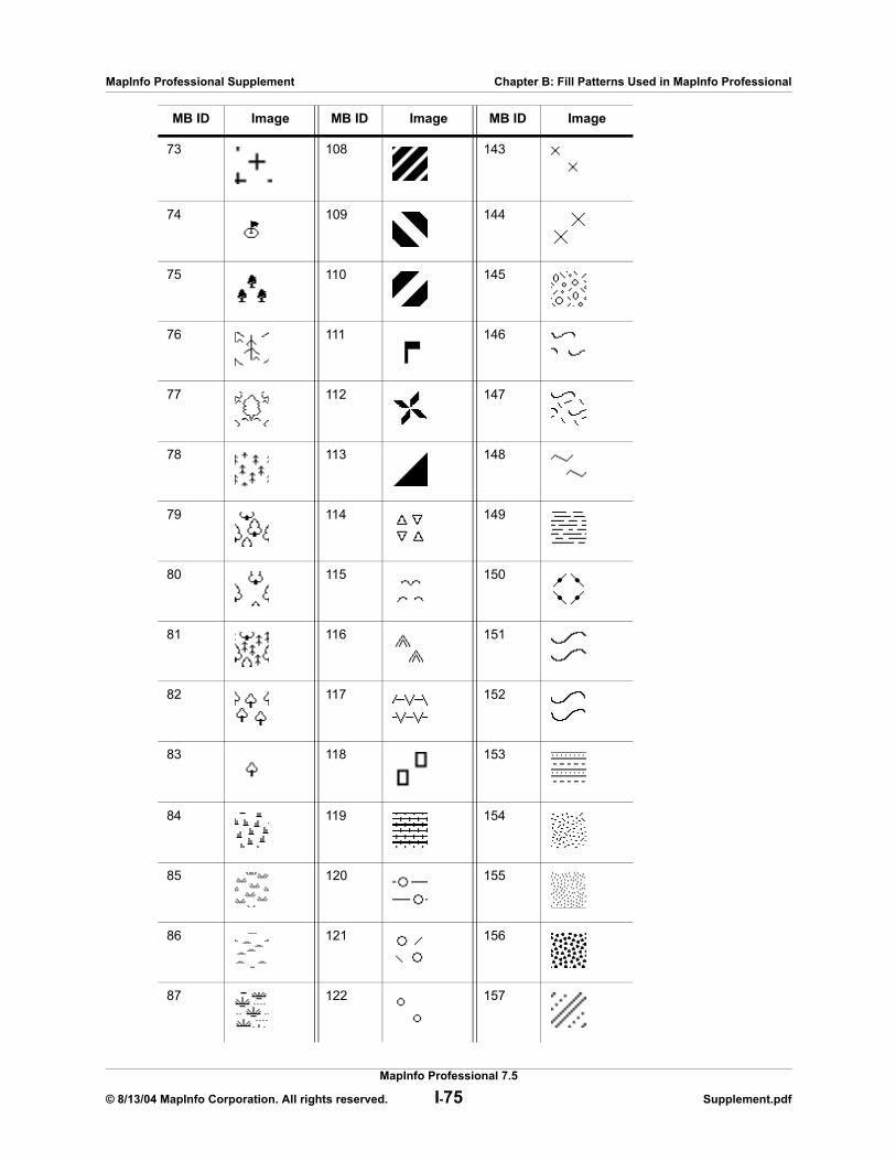
MapInfo Professional Supplement Chapter B: Fill Patterns Used in MapInfo Professional
73 108 143
74 109 144
75 110 145
76 111 146
77 112 147
78 113 148
79 114 149
80 115 150
81 116 151
82 117 152
83 118 153
84 119 154
85 120 155
86 121 156
87 122 157
MB ID Image MB ID Image MB ID Image
MapInfo Professional 7.5
© 8/13/04 MapInfo Corporation. All rights reserved. I-75 Supplement.pdf
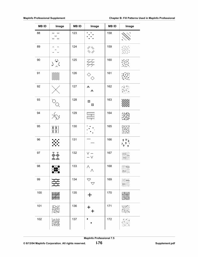
MapInfo Professional Supplement Chapter B: Fill Patterns Used in MapInfo Professional
88 123 158
89 124 159
90 125 160
91 126 161
92 127 162
93 128 163
94 129 164
95 130 165
96 131 166
97 132 167
98 133 168
99 134 169
100 135 170
101 136 171
102 137 172
MB ID Image MB ID Image MB ID Image
MapInfo Professional 7.5
© 8/13/04 MapInfo Corporation. All rights reserved. I-76 Supplement.pdf
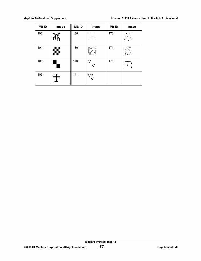
MapInfo Professional Supplement Chapter B: Fill Patterns Used in MapInfo Professional
103 138 173
104 139 174
105 140 175
106 141
MB ID Image MB ID Image MB ID Image
MapInfo Professional 7.5
© 8/13/04 MapInfo Corporation. All rights reserved. I-77 Supplement.pdf

C
New and Enhanced MapBasic Statements and FunctionsThese are the new statements and functions available for the MapInfo Professional 7.5 product.
Sections in this Appendix:
New statements and functions
Objects Move Statement . . . . . . . . . . . . . . . . . . . . . . . . . . . . . . I-79Objects Offset Statement . . . . . . . . . . . . . . . . . . . . . . . . . . . . . . I-80Offset() Function. . . . . . . . . . . . . . . . . . . . . . . . . . . . . . . . . . . . . I-81SphericalOffset() Function. . . . . . . . . . . . . . . . . . . . . . . . . . . . . I-81CartesianOffset() Function . . . . . . . . . . . . . . . . . . . . . . . . . . . . I-82OffsetXY() Function . . . . . . . . . . . . . . . . . . . . . . . . . . . . . . . . . . I-83SphericalOffsetXY() Function . . . . . . . . . . . . . . . . . . . . . . . . . . I-84CartesianOffsetXY() Function . . . . . . . . . . . . . . . . . . . . . . . . . . I-85
Enhanced statements
LayerInfo( ) function. . . . . . . . . . . . . . . . . . . . . . . . . . . . . . . . . . I-85Register Table Statement. . . . . . . . . . . . . . . . . . . . . . . . . . . . . . I-87Server Create Map Statement . . . . . . . . . . . . . . . . . . . . . . . . . . I-91TableInfo( ) function . . . . . . . . . . . . . . . . . . . . . . . . . . . . . . . . . . I-92

MapInfo Professional Supplement Chapter C: New and Enhanced MapBasic Statements and Functions
Objects Move StatementPurpose
Objects Move moves the objects obtained from the current selection within the input table.
SyntaxObjects Move
Angle angleDistance distance[Units unit][Type {Spherical | Cartesian}]
Description
Objects Move moves the objects within the input table. The source objects are obtained from the current selection. The resulting objects replace the input objects. No data aggregation is performed or necessary, since the data associated with the original source objects is unchanged.
The object is moved in the direction represented by angle, measured from the positive X-axis (east) with positive angles being counterclockwise, and offset at a distance given by the distance parameter. The distance is in the units specified by unit parameter, if present. If the Units clause is not present, then the current distance unit is the default. By default, MapBasic uses miles as the distance unit; to change this unit, see the Set Distance Units statement.
The optional Type sub-clause lets you specify the type of distance calculation used to create the offset. If the Spherical type is used, then the calculation is done by mapping the data into a Latitude/Longitude On Earth projection and using distance measured using Spherical distance calculations. If the Cartesian type is used, then the calculation is done by considering the data to be projected to a flat surface and distances are measured using cartesian distance calculations. If the Type sub-clause is not present, then the Spherical distance calculation type is used. If the data is in a Latitude/Longitude Projection, then Spherical calculations are used regardless of the Type setting. If the data is in a NonEarth Projection, the Cartesian calculations are used regardless of the Type setting.
There are some considerations for Spherical measurements that do not hold for Cartesian measurements. If you move an object that is in Lat/Long, the shape of the object remains the same, but the area of the object will change. This is because you are picking one offset delta in degrees, and the actual measured distance for a degree is different at different locations.
For the Offset functions, the actual offset delta is calculated at some fixed point on the object (e.g., the center of the bounding box), and then that value is converted from the input units into the Coordinate System's units. If the coordinate system is Lat/Long, the conversion to degrees uses the fixed point. The actual converted distance measurement could vary at different locations on the object. The distance from the input object and the new offset object is only guaranteed to be exact at the single fixed point used.
ExampleObjects Move Angle 45 Distance 100 Units “mi” Type Spherical
MapInfo Professional 7.5
© 8/13/04 MapInfo Corporation. All rights reserved. I-79 Supplement.pdf
MapInfo Professional Supplement Chapter C: New and Enhanced MapBasic Statements and Functions
Objects Offset StatementPurpose
Objects Offset copies objects, obtained from the current selection, offset from the original objects.
SyntaxObjects Offset
[Into Table intotable]Angle angleDistance distance[Units unit] [Type {Spherical | Cartesian}][Data column = expression [, column = expression ...]]
Description
Objects Offset makes a new copy of objects offset from the original source objects. The source objects are obtained from the current selection. The resulting objects are placed in the Into Table, if the Into clause is present. Otherwise, the objects are placed into the same table as the input objects are obtained from (i.e., the base table of the selection).
The object is moved in the direction represented by angle, measured from the positive X-axis (east) with positive angles being counterclockwise, and offset at a distance given by the distance parameter. The distance is in the units specified by unit parameter, if present. If the Units clause is not present, then the current distance unit is the default. By default, MapBasic uses miles as the distance unit; to change this unit, see the Set Distance Units statement.
The optional Type sub-clause lets you specify the type of distance calculation used to create the offset. If the Spherical type is used, then the calculation is done by mapping the data into a Latitude/Longitude On Earth projection and using distance measured using Spherical distance calculations. If the Cartesian type is used, then the calculation is done by considering the data to be projected to a flat surface and distances are measured using cartesian distance calculations. If the Type sub-clause is not present, then the Spherical distance calculation type is used. If the data is in a Latitude/Longitude Projection, then Spherical calculations are used regardless of the Type setting. If the data is in a NonEarth Projection, the Cartesian calculations are used regardless of the Type setting.
If you specify a Data clause, the application performs data aggregation.
There are some considerations for Spherical measurements that do not hold for Cartesian measurements. If you move an object that is in Lat/Long, the shape of the object remains the same, but the area of the object will change. This is because you are picking one offset delta in degrees, and the actual measured distance for a degree is different at different locations.
For the Offset functions, the actual offset delta is calculated at some fixed point on the object (e.g., the center of the bounding box), and then that value is converted from the input units into the Coordinate System's units. If the coordinate system is Lat/Long, the conversion to degrees uses the fixed point. The actual converted distance measurement could vary at different locations on the object. The distance from the input object and the new offset object is only guaranteed to be exact at the single fixed point used.
MapInfo Professional 7.5
© 8/13/04 MapInfo Corporation. All rights reserved. I-80 Supplement.pdf
MapInfo Professional Supplement Chapter C: New and Enhanced MapBasic Statements and Functions
ExampleObjects Offset Into Table c:\temp\table1.tbl Angle 45 Distance 100 Units “mi” Type Spherical
Offset() FunctionPurpose
Returns a copy of the input object offset by the specified distance and angle.
SyntaxOffset(object, angle, distance, units)
where:object is the object being offset, angle is the angle to offset the object,distance is the distance to offset the object, andunits is a string representing the unit in which to measure distance.
Return Value
Object
Description
This function produces a new object that is a copy of the input object offset by distance along angle (in degrees with horizontal in the positive X-axis being 0 and positive being counterclockwise). The unit string, similar to that used for ObjectLen or Perimeter, is the unit for the distance value. The DistanceType used is Spherical unless the Coordinate System is NonEarth. For NonEarth, Cartesian DistanceType is automatically used. The coordinate system used is the coordinate system of the input object.
There are some considerations for Spherical measurements that do not hold for Cartesian measurements. If you move an object that is in Lat/Long, the shape of the object remains the same, but the area of the object will change. This is because you are picking one offset delta in degrees, and the actual measured distance for a degree is different at different locations.
For the Offset functions, the actual offset delta is calculated at some fixed point on the object (e.g., the center of the bounding box), and then that value is converted from the input units into the Coordinate System's units. If the coordinate system is Lat/Long, the conversion to degrees uses the fixed point. The actual converted distance measurement could vary at different locations on the object. The distance from the input object and the new offset object is only guaranteed to be exact at the single fixed point used.
ExampleOffset(Rect, 45, 100, “mi”)
SphericalOffset() FunctionPurpose
Returns a copy of the input object offset by the specified distance and angle using a spherical DistanceType.
MapInfo Professional 7.5
© 8/13/04 MapInfo Corporation. All rights reserved. I-81 Supplement.pdf
MapInfo Professional Supplement Chapter C: New and Enhanced MapBasic Statements and Functions
SyntaxSphericalOffset(object, angle, distance, units)
where:object is the object being offset, angle is the angle to offset the object,distance is the distance to offset the object, andunits is a string representing the unit in which to measure distance.
Return Value
Object
Description
This function produces a new object that is a copy of the input object offset by distance along angle (in degrees with horizontal in the positive X-axis being 0 and positive being counterclockwise). The unit string, similar to that used for ObjectLen or Perimeter, is the unit for the distance value. The DistanceType used is Spherical. If the Coordinate System of the input object is NonEarth, an error will occur, since Spherical DistanceTypes are not valid for NonEarth. This is signified by returning a NULL object. The coordinate system used is the coordinate system of the input object.
There are some considerations for Spherical measurements that do not hold for Cartesian measurements. If you move an object that is in Lat/Long, the shape of the object remains the same, but the area of the object will change. This is because you are picking one offset delta in degrees, and the actual measured distance for a degree is different at different locations.
For the Offset functions, the actual offset delta is calculated at some fixed point on the object (for example, the center of the bounding box), and then that value is converted from the input units into the Coordinate System's units. If the coordinate system is Lat/Long, the conversion to degrees uses the fixed point. The actual converted distance measurement could vary at different locations on the object. The distance from the input object and the new offset object is only guaranteed to be exact at the single fixed point used.
ExampleSphericalOffset(Rect, 45, 100, “mi”)
CartesianOffset() FunctionPurpose
Returns a copy of the input object offset by the specified distance and angle using a Cartesian DistanceType.
SyntaxCartesianOffset(object, angle, distance, units)
where:object is the object being offset, angle is the angle to offset the object,distance is the distance to offset the object, andunits is a string representing the unit in which to measure distance.
MapInfo Professional 7.5
© 8/13/04 MapInfo Corporation. All rights reserved. I-82 Supplement.pdf

MapInfo Professional Supplement Chapter C: New and Enhanced MapBasic Statements and Functions
Return Value
Object
Description
This function produces a new object that is a copy of the input object offset by distance along angle (in degrees with horizontal in the positive X-axis being 0 and positive being counterclockwise). The unit string, similar to that used for ObjectLen or Perimeter, is the unit for the distance value. The DistanceType used is Cartesian. If the Coordinate System of the input object is Lat/Long, an error will occur, since Cartesian DistanceTypes are not valid for Lat/Long. This is signified by returning a NULL object. The coordinate system used is the coordinate system of the input object.
There are some considerations for Spherical measurements that do not hold for Cartesian measurements. If you move an object that is in Lat/Long, the shape of the object remains the same, but the area of the object will change. This is because you are picking one offset delta in degrees, and the actual measured distance for a degree is different at different locations.
For the Offset functions, the actual offset delta is calculated at some fixed point on the object (e.g., the center of the bounding box), and then that value is converted from the input units into the Coordinate System's units. If the coordinate system is Lat/Long, the conversion to degrees uses the fixed point. The actual converted distance measurement could vary at different locations on the object. The distance from the input object and the new offset object is only guaranteed to be exact at the single fixed point used.
ExampleCartesianOffset(Rect, 45, 100, “mi”)
OffsetXY() FunctionPurpose
Returns a copy of the input object offset by the specified X and Y offset values.
SyntaxOffsetXY(object, xoffset, yoffset, units)
where:object is the object being offset,xoffset and yoffset are the distance along the x and y axes to offset the object, andunits is a string representing the unit in which to measure distance.
Return Value
Object
Description
This function produces a new object that is a copy of the input object offset by xoffset along the X-axis and yoffset along the Y-axis. The unit string, similar to that used for ObjectLen or Perimeter, is the unit for the distance values. The DistanceType used is Spherical unless the Coordinate System is NonEarth. For NonEarth, Cartesian DistanceType is automatically used. The coordinate system used is the coordinate system of the input object.
MapInfo Professional 7.5
© 8/13/04 MapInfo Corporation. All rights reserved. I-83 Supplement.pdf
MapInfo Professional Supplement Chapter C: New and Enhanced MapBasic Statements and Functions
There are some considerations for Spherical measurements that do not hold for Cartesian measurements. If you move an object that is in Lat/Long, the shape of the object remains the same, but the area of the object will change. This is because you are picking one offset delta in degrees, and the actual measured distance for a degree is different at different locations.
For the Offset functions, the actual offset delta is calculated at some fixed point on the object (e.g., the center of the bounding box), and then that value is converted from the input units into the Coordinate System's units. If the coordinate system is Lat/Long, the conversion to degrees uses the fixed point. The actual converted distance measurement could vary at different locations on the object. The distance from the input object and the new offset object is only guaranteed to be exact at the single fixed point used.
ExampleOffsetXY(Rect, 92, -22, “mi”)
SphericalOffsetXY() FunctionPurpose
Returns a copy of the input object offset by the specified X and Y offset values using a spherical DistanceType.
SyntaxSphericalOffsetXY(object, xoffset, yoffset, units)
where:object is the object being offset,xoffset and yoffset are the distance along the x and y axes to offset the object, andunits is a string representing the unit in which to measure distance.
Return Value
Object
Description
This function produces a new object that is a copy of the input object offset by xoffset along the X-axis and yoffset along the Y-axis. The unit string, similar to that used for ObjectLen or Perimeter, is the unit for the distance values. The DistanceType used is Spherical. If the Coordinate System of the input object is NonEarth, an error will occur, since Spherical DistanceTypes are not valid for NonEarth. This is signified by returning a NULL object. The coordinate system used is the coordinate system of the input object.
There are some considerations for Spherical measurements that do not hold for Cartesian measurements. If you move an object that is in Lat/Long, the shape of the object remains the same, but the area of the object will change. This is because you are picking one offset delta in degrees, and the actual measured distance for a degree is different at different locations.
For the Offset functions, the actual offset delta is calculated at some fixed point on the object (e.g., the center of the bounding box), and then that value is converted from the input units into the Coordinate System's units. If the coordinate system is Lat/Long, the conversion to degrees uses the fixed point. The actual converted distance measurement could vary at different locations on the object. The distance from the input object and the new offset object is only guaranteed to be exact at the single fixed point used.
MapInfo Professional 7.5
© 8/13/04 MapInfo Corporation. All rights reserved. I-84 Supplement.pdf
MapInfo Professional Supplement Chapter C: New and Enhanced MapBasic Statements and Functions
ExampleSphericalOffsetXY(Rect, 92, -22, “mi”)
CartesianOffsetXY() FunctionPurpose
Returns a copy of the input object offset by the specified X and Y offset values using a cartesian DistanceType.
SyntaxCartesianOffsetXY(object, xoffset, yoffset, units)
where:object is the object being offset,xoffset and yoffset are the distance along the x and y axes to offset the object, andunits is a string representing the unit in which to measure distance.
Return Value
Object
Description
This function produces a new object that is a copy of the input object offset by xoffset along the X-axis and yoffset along the Y-axis. The unit string, similar to that used for ObjectLen or Perimeter, is the unit for the distance values. The DistanceType used is Cartesian. If the Coordinate System of the input object is Lat/Long, an error will occur, since Cartesian DistanceTypes are not valid for Lat/Long. This is signified by returning a NULL object. The coordinate system used is the coordinate system of the input object.
There are some considerations for Spherical measurements that do not hold for Cartesian measurements. If you move an object that is in Lat/Long, the shape of the object remains the same, but the area of the object will change. This is because you are picking one offset delta in degrees, and the actual measured distance for a degree is different at different locations.
For the Offset functions, the actual offset delta is calculated at some fixed point on the object (e.g., the center of the bounding box), and then that value is converted from the input units into the Coordinate System's units. If the coordinate system is Lat/Long, the conversion to degrees uses the fixed point. The actual converted distance measurement could vary at different locations on the object. The distance from the input object and the new offset object is only guaranteed to be exact at the single fixed point used.
ExampleCartesianOffsetXY(Rect, 92, -22, “mi”)
LayerInfo( ) function We have added a new Layer_Info_Type to accommodate the new WMS functionality.
Purpose
Returns information about a layer in a Map window.
Syntax
LayerInfo( map_window_id , layer_number , attribute )
MapInfo Professional 7.5
© 8/13/04 MapInfo Corporation. All rights reserved. I-85 Supplement.pdf
MapInfo Professional Supplement Chapter C: New and Enhanced MapBasic Statements and Functions
map_window_id is a Map window identifier
layer_number is the number of a layer in the current Map window (e.g., 1 for the top layer); to determine the number of layers in a Map window, call MapperInfo( )
attribute is a code indicating the type of information to return; see table in the MapBasic 7.0 documentation
Note: For information on the Return Value, the Restrictions, Attribute Codes, Description and the Example, see the MapBasic 7.0 documentation.
attribute code LayerInfo( ) Return Value
LAYER_INFO_TYPE SmallInt value, indicating this layer’s file type:
LAYER_INFO_TYPE_NORMAL for a normal layer;
LAYER_INFO_TYPE_COSMETIC for the Cosmetic layer;
LAYER_INFO_TYPE_IMAGE for a raster image layer;
LAYER_INFO_TYPE_THEMATIC for a thematic layer.
LAYER_INFO_TYPE_GRID for a grid image layer.
LAYER_INFO_TYPE_WMS for a layer from a Web Map Service
MapInfo Professional 7.5
© 8/13/04 MapInfo Corporation. All rights reserved. I-86 Supplement.pdf

MapInfo Professional Supplement Chapter C: New and Enhanced MapBasic Statements and Functions
Register Table StatementNote: Items bolded in the syntax section of this part represent the enhanced part of the
statementPurpose
Builds a MapInfo Professional table from a spreadsheet, database, text file, raster, or grid image.
SyntaxRegister Table source_file {Type “NATIVE” |
Type “DBF” [Charset char_set] |Type “ASCII” [Delimiter delim_char] [Titles] [CharSet char_set] |Type “WKS” [Titles] [Range range_name] |Type “WMS” [Coordsys coordsys_string [CharSet char_set]
[Into destination_file]Type “XLS” [Titles] [Range range_name] |Type “Access” Table table_name [Password pwd] [CharSet char_set]Type ODBC Connection {Handle ConnectionNumber | ConnectionString}
Toolkit toolkitname Cache {On | OFF}Type "GRID" | Type "RASTER" [ControlPoints (MapX1, MapY1) (RasterX1, RasterY1),
(MapX2, MapY2) (RasterX2, RasterY2),(MapX3, MapY3) (RasterX3, RasterY3) [, ...]] [CoordSys ... ]
Type "SHAPEFILE" [Charset char_set] CoordSys... [PersistentCache {On | Off}][Symbol...] [Linestyle Pen(...)] [Regionstyle Pen(...)Brush(...)] [Interactive] [Into destination_file]
source_file is a string that specifies the name of an existing database, spreadsheet, text file, raster, or grid image. If you are registering an Access table, this argument must identify a valid Access database.
char_set is the name of a character set; see the separate CharSet discussion.
delim_char specifies the character used as a column delimiter. If the file uses Tab as the delimiter, specify 9. If the file uses commas, specify 44.
range_name is a string indicating a named range (e.g., “MyTable”) or a cell range (e.g., an Excel range can be specified as “Sheet1!R1C1:R9C6” or as “Sheet1!A1:F9”).
table_name is a string that identifies an Access table.
pwd is the database-level password for the database, to be specified when database security is turned on.
ConnectionNumber is an integer value that identifies an existing connection to an ODBC database.
ConnectionString is a string used to connect to a database server. See the Server Connect function.
toolkitname is “ODBC” or “ORAINET.”
SQLQuery is the SQL query used to define the MapInfo table.
MapInfo Professional 7.5
© 8/13/04 MapInfo Corporation. All rights reserved. I-87 Supplement.pdf
MapInfo Professional Supplement Chapter C: New and Enhanced MapBasic Statements and Functions
ControlPoints are optional, but can be specified if the type is Grid or Raster. If the ControlPoints token is specified, it must be followed by at least 3 pairs of Map and Raster coordinates which are used to georegister an image. If the ControlPoints are specified, they will override and replace any control points associated with the image or an associated World file.
The CoordSys clause is optional, but can be specified if the type is Grid or Raster. If a CoordSys is specified, it will override and replace any coordsys associated with the image. This is useful when registering a raster image that has an associated World file.
In the case of Shapefiles, the CoordSys clause is mandatory. The compiler will indicate an error if it is missing.
PersistentCache On specifies if .map and .id files generated during the opening of Shapefiles are saved on hard disk after closing a table. If PersistentCache is set to Off, then these .map and .id files will be deleted after closing a table and will be generated each time the table is opened.
Symbol (...) clause specifies the symbol style to be used for a point object type created from a shapefile
Linestyle Pen (...) clause specifies the line style to be used for a line object type created from a shapefile
Regionstyle Pen (...) Brush(...) clause specifies the line style and fill style to be used for a region object type created from a shapefile
The Interactive keyword is optional, but can be specified if the type is Grid or Raster. If the Interactive keyword is specified, the user will be prompted for any missing control point or projection information. If the Interactive keyword is not specified, a .tab file will be generated without user input and will be created as though the user had selected “Display” when opening a raster image from the Open dialog box.
destination_file specifies the name to give to the MapInfo table (.tab file). This string may include a path; if it does not include a path, the file is built in the same directory as the source file.
Description
Before you can use a non-native file (e.g., a dBASE file) in MapInfo, you must register the file. The Register Table statement tells MI Pro to examine a non-native file (e.g., filename.DBF) and build a corresponding table file (filename.tab). Once the Register Table operation has built a table file, you can access the file as an MapInfo table.
The Register Table statement does not copy or alter the original data file. Instead, it scans the data, determines the datatypes of the columns, and creates a separate table file. The table is not opened automatically. To open the table, use an Open Table statement.
Note: Each data file need only be registered once. Once the Register Table operation has built the appropriate table file, subsequent MI Pro sessions simply Open the table, rather than repeat the Register Table operation.
The Type clause specifies where the file came from originally. This consists of the keyword Type, followed by one of the following character constants: NATIVE, DBF, ASCII, WKS, XLS, Raster, Access, or Grid. The other information is necessary for preparing certain types of tables. If the type of file being registered is a grid, the coordsys string will be read from the grid file and a MapInfo .tab file will be created. If a raster file is being registered, the .tab file that is generated will be the same as if the user selected “Display” when opening a raster image from the Open dialog box.
MapInfo Professional 7.5
© 8/13/04 MapInfo Corporation. All rights reserved. I-88 Supplement.pdf
MapInfo Professional Supplement Chapter C: New and Enhanced MapBasic Statements and Functions
If the type of file being registered is a grid, the coordsys string will be read from the grid file and a MapInfo .tab file will be created. If a raster file is being registered, the .tab file that is generated depends upon if georegistration information can be found in the image file or associated World file.
The CharSet clause specifies a character set. The char_set parameter should be a string such as “MacRoman” or “WindowsLatin1”. If you omit the CharSet clause, MI Pro uses the default character set for the hardware platform that is in use at run-time. See the CharSet clause discussion for more information.
The Delimiter clause is followed by a string containing the delimiter character. The default delimiter is a TAB. The Titles clause indicates that the row before the range of data in the worksheet should be used as column titles. The Range clause allows the specification of a named range to use. The Into clause is used to override the table name or location of the .tab file. By default, it will be named the same as the data file, and stored in the same directory. However, when reading a read-only device such as a CD-ROM, you need to store the .tab file on a volume that is not read-only.
Registering Access Tables
When you register an Access table, MI Pro checks for a counter column with a unique index. If there is already a counter column, MI Pro registers that column in the .tab file. The column is read-only.
If the Access table does not have a counter column, MI Pro modifies the Access table by adding a column called MAPINFO_ID with the counter datatype. In this case, the counter column does not display in MapInfo.
Note: Do not alter the counter column in any way. It must be exclusively maintained automatically by MapInfo.
Access datatypes are translated into the closest MapInfo datatypes. Special Access datatypes, such as OLE objects and binary fields, are not editable in MapInfo Professional.
Registering ODBC Tables
Before accessing a table live from a remote database, it is highly recommended that you first open a map table (e.g., canada.tab) for the database table. If you don't open a map table, the entire database table will be downloaded all at once, which could take a long time.
Open a map table and zoom in to an area that corresponds to a subset of rows you wish to see from the database table. For example, if you want to download rows pertaining to Ontario, zoom in to Ontario on the map. As a result, when you open the database table, only rows within the map window's MBR (minimum bounding rectangle), in this case Ontario, will be downloaded.
This is a list of known problems/issues with live access:
• Every table must have a single unique key column. • FastEdit is not supported.• With MS ACCESS if the key is character, it will not display rows where the key value is
less than the full column width e.g., if the key is char(5) the value 'aaaa' will look like a deleted row.
• For Live Access, the ReadOnly checkbox on the save table dialogue will be grayed out.• Changes made by another user are not visible until a browser is scrolled or somehow
refreshed. Inserts by another user are not seen until either: 1). An MBR search returns the
MapInfo Professional 7.5
© 8/13/04 MapInfo Corporation. All rights reserved. I-89 Supplement.pdf

MapInfo Professional Supplement Chapter C: New and Enhanced MapBasic Statements and Functions
row or 2). PACK command is issued In addition if cache is on another users updates may not appear until the cache is invalidated by a pan or zooming out.
• There will be a problem if a client side join (through SQL Select menu item or MapBasic) is done against 2 or more SPATIALWARE tables that are stored in different coordinate systems. This is not an efficient thing to do (it is better to do the join in the SQL statement that defines the table) but it is a problem in the current build.
• Oracle 7 tables that are indexed on a decimal field larger than 8 bytes will cause MI Pro to crash when editing.
• If the Cache OFF statement is before the connection string an error will be generated at compile time.
Registering Shapefiles
When you register shapefiles, they can be opened in MapInfo Professional with read-only access. Since a shapefile itself does not contain projection information, you must specify a CoordSys clause. It is also possible to set styles that will be used when shapefile objects are displayed in MapInfo Professional. Projection and style information is stored as metadata in the TAB file.
Examples
Example 1Register Table ”c:\mapinfo\data\rpt23.dbf” Type ”DBF” Into ”Report23”
Open Table ”c:\mapinfo\data\Report23”
Example 2Open Table ”C:\Data\CANADA\Canada.tab” InteractiveMap From Canadaset map redraw offSet Map Zoom 1000 Units ”mi”set map redraw onRegister Table ”odbc_cancaps”
TYPE ODBC TABLE ”Select * From informix.can_caps” CONNECTION
DSN=ius_adak;UID=informix;PWD=informix;DATABASE=sw;HOST=adak;SERVER=adak_tli;SERVICE=sqlexec;PROTOCOL=onsoctcp;”
Into ”D:\MI\odbc_cancaps.tab”
Open Table ”D:\MI\odbc_cancaps.tab” InteractiveMap From odbc_cancaps
Example 3
Registering a completely georeferenced raster image (the raster handler can return at least 3 control points and a projection)
Register Table "GeoRef.tif" type "raster" into "GeoRef.tab"
Example 4
Registering a raster image that has an associated World file containing control point information, but no projection.
MapInfo Professional 7.5
© 8/13/04 MapInfo Corporation. All rights reserved. I-90 Supplement.pdf
MapInfo Professional Supplement Chapter C: New and Enhanced MapBasic Statements and Functions
Register Table "RasterWithWorld.tif" type "raster" coordsys earth projection 9, 62, "m", -96, 23, 29.5, 45.5, 0, 0 into "RasterWithWorld.tab"
Example 5
Registering a raster image that has no control point or projection information.
Register Table "NoRegistration.BMP" type "raster" controlpoints (1000,2000) (1,2), (2000,3000) (2, 3), (5000,6000) (5,6) coordsys earth projection 9, 62, "m", -96, 23, 29.5, 45.5, 0, 0 into "NoRegistration.tab"
Example 6
The following example registers a shapefile.
Register Table "C:\Shapefiles\CNTYLN.SHP" TYPE SHAPEFILE Charset "WindowsLatin1" CoordSys Earth Projection 1, 33 PersistentCache Off linestyle Pen (2,26,16711935) Into "C:\Temp\CNTYLN.tab"Open Table "C:\Temp\CNTYLN.tab" Interactive Map From CNTYLN
See Also
Open Table, Create Table
Server Create Map StatementNote: Items bolded in the syntax section of this part represent the enhanced part of the
statementPurpose
This function identifies the spatial information for a server table. It does not alter the table to add the spatial columns.
A new object type clause in the Server Create Map statement allows you to specify objects as regions, lines, or all objects. If no object type clause is specified, the default is points.
SyntaxServer ConnectionNumber Create Map
For DBMSTableNameType { see Maptypes below }CoordSys ...[MapBounds {Data|Coordsys|Values (x1, y1) (x2, y2)} ][ObjectType { Point | Line | Region | ALL } ][Symbol (...) ][Linestyle Pen(...) ][Regionstyle Pen(...) Brush(...) ][StyleType style_number (0 or 1) [ Column column_name ]
ConnectionNumber An integer value that identifies the specific connection.
DBMSTableName The table identifier for the DBMS table. This is case sensitive and should contain the schema/owner.
MapTypes One of the mappable DBMS datatype options listed here:
• MICODE MICODEColName (XCoordColName, YCoordColName) — MICODE spatial index key column and numeric X and Y coordinate columns. Column names are case sensitive.
MapInfo Professional 7.5
© 8/13/04 MapInfo Corporation. All rights reserved. I-91 Supplement.pdf

MapInfo Professional Supplement Chapter C: New and Enhanced MapBasic Statements and Functions
• XYINDEX (XCoordColName, YCoordColName) — Numeric X and Y coordinate columns.• ORA_SP SDO_Spatial_Column_Name — Oracle Spatial• IUS_SW ST_Spatial_Column_Name — SpatialWare IUS Blade• IUS_MM_SW columnname — MapInfo MapMarker Geocoding DataBlade for SpatialWare• IUS_MM_XY columnname — MapInfo MapMarker Geocoding DataBlade for XY• SPATIALWARE — SpatialWare for SQL Server
CoordSys ... This clause specifies the coordinate system and projection to be used. For Oracle Spatial, this is not required because it is determined from the Oracle Server metadata.
ObjectType clause This clause specifies the type of object in the table, defaults to points.
Symbol (...) clause This clause specifies the symbol style to be used for a point object type
Linestyle Pen (...) clause This clause specifies the line style to be used for a line object type
Regionstyle Pen (...) Brush(...) clause This clause specifies the line style and fill style to be used for a region object type
StyleType sets per row symbology. The Column token and argument need to be present when StyleType is set to 1 (one). When style_number is set to zero, the Column token is ignored and the rendition columns in the MAPCATALOG are cleared.
Description
The Server Create Map statement makes a table linked to a remote database mappable. For a SpatialWare or Oracle Spatial table, you can make the table mappable for points, lines, or regions. For all other tables, you can make a table mappable for points only. Any MapInfo table may be displayed in a Browser, but only a mappable table may have graphical objects attached. Only mappable tables can display in Map windows.
Note: If Oracle9i is the server and the coordinate system is specified Lat/Long without specifying the datum, the default datum World Geodetic System 1984(WGS 84) is assigned as the coordinate system. This behavior is consistent with the Server Create Table statement and EasyLoader.
The MapBounds option allows you to specify what to store for the entire/default table view bounds in the MapCatalog. The default is Data which calculates the bounds of all the data in the layer. (For programs compiled before 7.5, the default will be CoordSys.)
The Coordsys MapBounds option stores the coordinate system bounds. This is not recommended as it may cause the entire layer.default view to appear empty if the coordsys bounds are significantly greater than the bounds of the actual data. Most users are zoomed out too far to see their data using this option.
The Values option lets you specify your own bounds values for the MapCatalog.
TableInfo( ) function Purpose
Returns information about an open table.
Syntax
TableInfo( table_id , attribute )
MapInfo Professional 7.5
© 8/13/04 MapInfo Corporation. All rights reserved. I-92 Supplement.pdf
MapInfo Professional Supplement Chapter C: New and Enhanced MapBasic Statements and Functions
table_id is a String representing a table name, a positive Integer table number, or 0 (zero)
attribute is an Integer code indicating which aspect of the table to return
Note: For information on the Return Values, the Restrictions, Attribute Codes, Descriptions and the Examples, see the MapBasic 7.0 documentation.
attribute code TableInfo( ) returns
TAB_INFO_TYPE SmallInt result, indicating the type of table. The returned value will match one of these values: TAB_TYPE_BASE (if a normal or seamless table) TAB_TYPE_RESULT (if results of a query) TAB_TYPE_IMAGE (if table is a raster image) TAB_TYPE_VIEW (if table is actually a view; for example, StreetInfo tables are actually views) TAB_TYPE_LINKED (if this table is linked).TAB_TYPE_WMS (if table is from a Web Map Ser-vice)
MapInfo Professional 7.5
© 8/13/04 MapInfo Corporation. All rights reserved. I-93 Supplement.pdf

MapInfo Professional Supplement Chapter C: New and Enhanced MapBasic Statements and Functions
MapInfo Professional 7.5
© 8/13/04 MapInfo Corporation. All rights reserved. I-94 Supplement.pdf
Part II: MapInfo Professional 7.8 Supplement
This part contains the supplement for the MapInfo Professional 7.8 product. We are including this in this document so that you can have one resource for new features for the post-7.0 MapInfo Professional product.
Topics:
Upgrading to MapInfo Professional 7.8 . . . . . . . . . . . . . . . . . . . . . . . . . . . . . . . . . . . II-96What’s New in MapInfo Professional 7.8 . . . . . . . . . . . . . . . . . . . . . . . . . . . . . . . . . II-112Working with Coordinate Systems and Projections . . . . . . . . . . . . . . . . . . . . . . . . II-156High-Resolution Custom Symbols . . . . . . . . . . . . . . . . . . . . . . . . . . . . . . . . . . . . . . II-186New and Enhanced MapBasic Statements and Functions . . . . . . . . . . . . . . . . . . . II-190

1
Upgrading to MapInfo Professional 7.8Thank you for upgrading to MapInfo Professional® 7.8!
This section covers the upgrade to MapInfo Professional 7.8 and includes instructions for installing the product. In addition, there are instructions in preparing for the installation and for handling issues that may arise as part of the upgrade process.
Sections in this Chapter:
System Requirements for MapInfo Professional 7.8. . . . . . . . II-97Before You Upgrade to MapInfo Professional 7.8 . . . . . . . . . . II-98Upgrading MapInfo Professional 7.8 . . . . . . . . . . . . . . . . . . . . II-98Setting your Database Connection Preferences . . . . . . . . . . II-103Modifying, Repairing, or Removing MapInfo Pro . . . . . . . . . II-104

MapInfo Professional Supplement Chapter 1: Upgrading to MapInfo Professional 7.8
System Requirements for MapInfo Professional 7.8
These are the system requirements for MapInfo Professional 7.8:
Note: The Installer requires that your TEMP variable be set to a valid directory.
Handling Database ConnectivityMapInfo Professional supports the following relational database engines:
• SQL Server 2000 (SpatialWare 4.8.1)• Informix 9.4 (SpatialWare 4.5.2) on Solaris 32-bit • Oracle Spatial 10G, 9iR2 and 8.17• Oracle Locator 9iR2
Further, using ODBC drivers, you can access your data from MapInfo Professional using:
• Oracle ODBC Driver 9.2.0.6• SQL Server• Informix 3.82
To make your database work more productive, MapInfo Professional 7.8 provides an interface for opening remote tables called the RDBMS Toolkit. This toolkit gives you the ability to save tables to a remote database using Save Copy As and to create new tables on remote databases. Additionally it gives you the means to create a new table from existing tables. The RDBMS Toolkit is available on the MapInfo web site.
You can also open tables of data from the following databases and make them mappable but only for point data:
• Oracle 9iR2• MS Access XP• MS SQL Server 2000• Informix 9.4
Operating Systems Memory Disk Space Monitor
Windows 98 SE, Windows 2000 Professional SP 4, Windows NT 4.0 Workstation SP 6a
32 MB of RAM with a minimum of a Pentium PC
MapInfo Pro-fessional 103 MBData 450 MB
16- or 24-bit color SVGA recommended
Windows XP Professional SP 1aWindows XP Home SP 1a
64 MB of RAM with a minimum of a Pentium PC
MapInfo Pro-fessional 103 MBData 450 MB
16- or 24-bit color SVGA recommended
MapInfo Professional 7.8
© 8/13/04 MapInfo Corporation. All rights reserved. II-97 Supplement.pdf

MapInfo Professional Supplement Chapter 1: Upgrading to MapInfo Professional 7.8
Before You Upgrade to MapInfo Professional 7.8
Before upgrading MapInfo Professional, record your serial number in an easy-to-remember place, such as the title page of the User Guide or Supplement. You need a valid serial number to complete the upgrade. Also, please complete the postage-paid registration card and return it to MapInfo Corporation. Additionally, you can register online by accessing the Contact Info option on the CD Browser.
If the MapInfo Professional 7.8 installer detects an existing version of the product, 6.0 or earlier, or detects that the product had been installed at some time, the installer copies the MAPINFOW.WOR, STARTUP.WOR and MAPINFOW.PRF from the operating system's system directory to <user profile root>\Application Data\MapInfo\MapInfo.
Application data (appdata) files are the non-executable data files that MapInfo Professional uses during operation.
Navigating the MapInfo Professional 7.8 CD BrowserThe initial screen of the MapInfo Professional 7.8 CD Browser includes these options:
• Install Products: From this option you can install MapInfo Professional (including DBMS support and translators), free data, access to the documentation, and Install Utilities, including: ECW Compressor, GPS, and Meta Data Browser.
• What’s New: Display a list and description of new and enhanced features.• Online Reference: MapInfo Professional 7.8 provides the following online reference
documents: The MapInfo Professional Supplement, MapBasic Reference, Crystal Reports User’s Guide, the MapInfo Professional Printing Guide, as well as the Adobe Acrobat Reader.
• Run MapInfo Tutorial: From this option you can access the MapInfo Tutorial from the MapInfo web site to learn more about the basic features of MapInfo Professional.
• Other Products: Display information about MapBasic, MapInfo Discovery, and MapInfo Pro for SQL Server.
• Contact Information: Where ever you are, MapInfo is there to help you. Contact us at any of these locations or visit us on the world wide web at www.mapinfo.com!
• Register Online: We have simplified the registration process. Simply click this entry and the wizard walks you through the registration process quickly.
• Browse CD: From this option you can review the contents of the CD. There are additional utilities that may be useful to you that are only available when you browse.
• Exit: From this option you can close the CD Browser application.
Upgrading MapInfo Professional 7.8
CAUTION: We strongly recommend that you exit from all Windows programs before beginning the upgrade process.
You must have Administrator rights to run the Installer on NT/2000 and Windows XP.
MapInfo Professional 7.8
© 8/13/04 MapInfo Corporation. All rights reserved. II-98 Supplement.pdf
MapInfo Professional Supplement Chapter 1: Upgrading to MapInfo Professional 7.8
If your Windows Start menu does not have a MapInfo program folder, the upgrade process creates this folder. If your Windows Start menu already has a MapInfo program folder, the upgrade process creates a new MapInfo icon within that folder.
MapInfo Professional now provides its application data files to each user. Called a Per-User install, this functionality runs the first time you run MapInfo Professional or MapInfo Professional client on a machine, and each time the MapInfo Professional Installer is run thereafter. The application data files include, among others, the Pen Styles file, Custom Symbols files, Graph Support files, and Thematic Legend templates. These files allow different users to have custom settings.
To upgrade MapInfo Professional:
1. On the LAUNCHER menu, click INSTALL PRODUCTS from the MapInfo Professional 7.8 CD Browser.
2. Click MAPINFO PROFESSIONAL INSTALLER. The Install Shield Wizard dialog box displays. Click NEXT to continue the upgrade process and display the License Information dialog box.
3. Click “I ACCEPT THE TERMS IN THE LICENSE AGREEMENT” to accept the terms and click NEXT to continue the upgrade. The Customer Information screen displays.
4. Type your name, organization name, and serial number in these required fields. Click NEXT to continue. The Setup Type dialog box displays.
5. Review the following installation types and determine which instructions are appropriate for your upgrade. Click one of the following and click NEXT to continue:• TYPICAL WORKSTATION INSTALLATION. Click this option if you will be using MapInfo
Professional as a desktop application requiring no remote database access or connectivity. See Typical Workstation Installation (7.8) on page II-99 to continue these upgrade instructions.
• CUSTOM WORKSTATION INSTALLATION. Click this option if you require ODBC or Oracle Spatial connectivity support. See Custom Workstation Installation (7.8) on page II-100 to continue the upgrade instructions.
• NETWORK INSTALLATION. Click this option if you are upgrading your MapInfo Professional network product. See Network Installation (7.8) on page II-102 to continue the upgrade instructions. These instructions are for network administrators only. After you upgrade MapInfo Professional on the network, follow the instructions for upgrading MapInfo Professional on client equipment in Setting Up Client Workstations (7.8) on page II-103.
If you have already upgraded to MapInfo Professional 7.8 or if the product has been previously installed, the Program Maintenance Screen displays. Select MODIFY, REPAIR, or REMOVE to continue. For assistance in completing this process, see Modifying, Repairing, or Removing MapInfo Pro on page II-104. If you find that you need to install ODBC drivers after installing MapInfo Professional, select the MODIFY option to add them.
Typical Workstation Installation (7.8)Choose this option to install MapInfo Professional program files, Online Help, Tools, Universal Translator, and Crystal Reports. The ArcLink translation utility is not installed with this option.
CAUTION: Make sure you have completed the directions in Upgrading MapInfo Professional 7.8 on page II-98 before beginning these instructions.
MapInfo Professional 7.8
© 8/13/04 MapInfo Corporation. All rights reserved. II-99 Supplement.pdf

MapInfo Professional Supplement Chapter 1: Upgrading to MapInfo Professional 7.8
To continue upgrading a typical workstation:
1. In the Setup Type dialog box, click TYPICAL WORKSTATION INSTALLATION; the Destination Folder screen displays.
Note: If you have an earlier version (or versions) of MapInfo Professional installed and you do not want to overwrite that version, create a new directory name in the next step.
2. Do one of the following:• Click NEXT to accept the destination folder indicated• Click CHANGE to create a new path in the Change Current Destination Folder dialog
box. Type the new path in the Folder name field and click OK to continue. Click NEXT to continue.
The Ready to Install the Program screen displays. Review your selections to ensure that the path is correct before moving on. Click BACK to return to the previous screens to make changes.
3. Click INSTALL to begin the upgrade. The Installing MapInfo Professional 7.8 screen displays with a progress bar indicating the status of the upgrade process.
4. After the upgrade is complete, the prompt: “Would you like to check our web site for any current updates to our product?” displays. If you have an Internet connection, check YES to be connected to the page of the MapInfo Corporation web site containing information about product updates. This ensures that you have the most up-to-the minute MapInfo Professional product available.
5. When the InstallShield Wizard Complete screen displays, choose FINISH to return to the Install Products screen.
Note: When you open MapInfo Professional 7.8 for the first time, the final installation and configuration process takes place. This happens automatically and does not require any additional work.
Custom Workstation Installation (7.8)Choose this upgrade type to select components and drivers within the MapInfo Professional 7.8 installation program. This is particularly useful if you need to install MapInfo ODBC Connectivity support and Oracle Spatial Object support.
CAUTION: Make sure you have completed the directions in Upgrading MapInfo Professional 7.8 on page II-98 before beginning these instructions.
To continue upgrading using the custom workstation instructions:
1. In the Setup Type dialog box, click CUSTOM WORKSTATION INSTALLATION; the Custom Setup dialog box displays.
MapInfo Professional 7.8
© 8/13/04 MapInfo Corporation. All rights reserved. II-100 Supplement.pdf
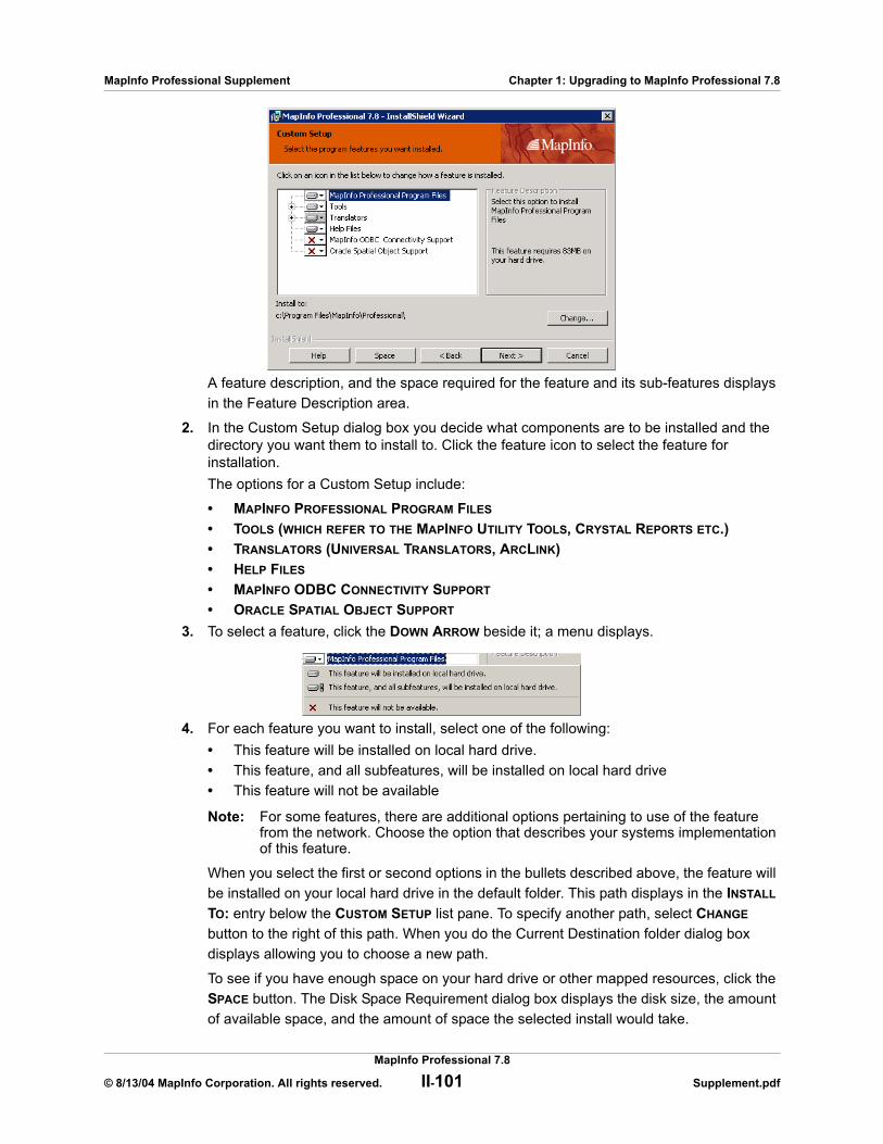
MapInfo Professional Supplement Chapter 1: Upgrading to MapInfo Professional 7.8
A feature description, and the space required for the feature and its sub-features displays in the Feature Description area.
2. In the Custom Setup dialog box you decide what components are to be installed and the directory you want them to install to. Click the feature icon to select the feature for installation. The options for a Custom Setup include:
• MAPINFO PROFESSIONAL PROGRAM FILES
• TOOLS (WHICH REFER TO THE MAPINFO UTILITY TOOLS, CRYSTAL REPORTS ETC.)• TRANSLATORS (UNIVERSAL TRANSLATORS, ARCLINK)• HELP FILES
• MAPINFO ODBC CONNECTIVITY SUPPORT
• ORACLE SPATIAL OBJECT SUPPORT
3. To select a feature, click the DOWN ARROW beside it; a menu displays.
4. For each feature you want to install, select one of the following:• This feature will be installed on local hard drive.• This feature, and all subfeatures, will be installed on local hard drive• This feature will not be available
Note: For some features, there are additional options pertaining to use of the feature from the network. Choose the option that describes your systems implementation of this feature.
When you select the first or second options in the bullets described above, the feature will be installed on your local hard drive in the default folder. This path displays in the INSTALL TO: entry below the CUSTOM SETUP list pane. To specify another path, select CHANGE button to the right of this path. When you do the Current Destination folder dialog box displays allowing you to choose a new path.
To see if you have enough space on your hard drive or other mapped resources, click the SPACE button. The Disk Space Requirement dialog box displays the disk size, the amount of available space, and the amount of space the selected install would take.
MapInfo Professional 7.8
© 8/13/04 MapInfo Corporation. All rights reserved. II-101 Supplement.pdf
MapInfo Professional Supplement Chapter 1: Upgrading to MapInfo Professional 7.8
Note: You can choose to not install a component. To do this, skip the feature entry entirely.
5. After you select all the custom options you want to install, click NEXT to display the READY TO INSTALL THE PROGRAM dialog box.
6. Click the INSTALL button to begin the installation of MapInfo Professional with the features you selected. The INSTALLING MAPINFO PROFESSIONAL 7.8 screen displays with a progress bar indicating the status of the upgrade process.
7. Install MapInfo Professional according to your selections.8. At the end of the upgrade, the prompt: “Would you like to check our web site for any
current updates to our product?” displays. If you have an Internet connection, click YES to access the MapInfo Corporation web site containing information about product updates.
9. When the InstallShield Wizard Complete screen displays, choose FINISH to return to the Install Products screen.
Note: When you open MapInfo Professional 7.8 for the first time, the final installation and configuration process takes place. This happens automatically and does not require any additional work.
Adding ODBC DriversYou add the ODBC drivers as part of the Custom Installation process. You can set your database connection preferences in Setting your Database Connection Preferences on page II-103.
Network Installation (7.8)Installing MapInfo Professional 7.8 on a network involves two separate procedures:
• Installing the product on a network drive (presumably done by the Network Administrator).• Setting up users with program manager icons, etc. (presumably done by the user).
Make sure you have completed the directions in Upgrading MapInfo Professional 7.8 on page II-98 before beginning these directions.
Choose this installation ONLY if you are a Network Administrator and have full rights to the network.
To continue upgrading MapInfo Professional 7.8 on a network:
1. Click NETWORK INSTALLATION; the Administrator Selection Screen displays.The options for a Network Setup include:
• MAPINFO PROFESSIONAL PROGRAM FILES
• TOOLS, TRANSLATORS
• HELP FILES
A feature description, and the space required for the feature, displays in the Feature Description area. Click the option icon to install it.
2. When you select a feature, a menu displays allowing you to choose to install and/or run the feature and its subfeatures from various locations, including your local hard drive or from CD. If you select the hard drive option, the feature will be installed in the path indicated; on your local hard drive in the folder indicated; to specify a different location, choose CHANGE to display the Current Destination folder screen.
MapInfo Professional 7.8
© 8/13/04 MapInfo Corporation. All rights reserved. II-102 Supplement.pdf

MapInfo Professional Supplement Chapter 1: Upgrading to MapInfo Professional 7.8
If you choose to install an option to your hard drive, the SPACE button is enabled; choose this button to display the Disk Space Requirement dialog box.
Note: You can choose to not install a feature by skipping it.
See Installing MapInfo Professional 7.8 on a Network Drive on page II-103 for additional details.
3. After the upgrade is complete, the prompt: “Would you like to check our web site for any current updates to our product?” displays. If you have an Internet connection, check YES to be connected to the page of the MapInfo Corporation Web site containing information about product updates.
4. When the InstallShield Wizard Complete screen displays, choose FINISH to return to the Install Products screen.
Installing MapInfo Professional 7.8 on a Network DriveThe procedure for installing MapInfo Professional on a network drive is the same as the regular installation procedure except for the following:
• Select Network Installation in the Setup Type screen.• Continue as in a Workstation Installation, selecting features, destination locations, etc.
The Network Installation alone does not install any files to the local hard drive.
Setting Up Client Workstations (7.8)To permit a user to use this network installation of MapInfo Professional, run SETUP.EXE:
1. Map a drive to the MapInfo Professional Install directory.2. Select RUN from the START menu. 3. Run SETUP.EXE from the [MapInfo install directory]\AddClient. The MapInfo Professional
7.8 Client Welcome screen displays. 4. Click NEXT. The License Information screen displays. 5. Click “I ACCEPT THE TERMS OF THE LICENSE AGREEMENT” and select NEXT. The Customer
Information screen displays with the network install values as the default. 6. Modify for the current instance and select NEXT.7. Click INSTALL to continue the installation.8. Click FINISH to complete the client installation.
Setting your Database Connection Preferences
If you have a favorite database connection setting, we have established a Startup preference setting to create that connection automatically at the beginning of your session.
To set Database Connection Startup preference:
1. In the OPTIONS menu, click PREFERENCES and then STARTUP to display the STARTUP PREFERENCES dialog box.
MapInfo Professional 7.8
© 8/13/04 MapInfo Corporation. All rights reserved. II-103 Supplement.pdf
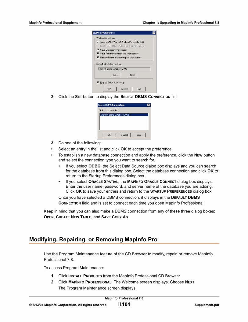
MapInfo Professional Supplement Chapter 1: Upgrading to MapInfo Professional 7.8
2. Click the SET button to display the SELECT DBMS CONNECTION list.
3. Do one of the following:• Select an entry in the list and click OK to accept the preference. • To establish a new database connection and apply the preference, click the NEW button
and select the connection type you want to search for. • If you select ODBC, the Select Data Source dialog box displays and you can search
for the database from this dialog box. Select the database connection and click OK to return to the Startup Preferences dialog box.
• If you select ORACLE SPATIAL, the MAPINFO ORACLE CONNECT dialog box displays. Enter the user name, password, and server name of the database you are adding. Click OK to save your entries and return to the STARTUP PREFERENCES dialog box.
Once you have selected a DBMS connection, it displays in the DEFAULT DBMS CONNECTION field and is set to connect each time you open MapInfo Professional.
Keep in mind that you can also make a DBMS connection from any of these three dialog boxes: OPEN, CREATE NEW TABLE, and SAVE COPY AS.
Modifying, Repairing, or Removing MapInfo Pro
Use the Program Maintenance feature of the CD Browser to modify, repair, or remove MapInfo Professional 7.8.
To access Program Maintenance:
1. Click INSTALL PRODUCTS from the MapInfo Professional CD Browser.2. Click MAPINFO PROFESSIONAL. The Welcome screen displays. Choose NEXT.
The Program Maintenance screen displays.
MapInfo Professional 7.8
© 8/13/04 MapInfo Corporation. All rights reserved. II-104 Supplement.pdf
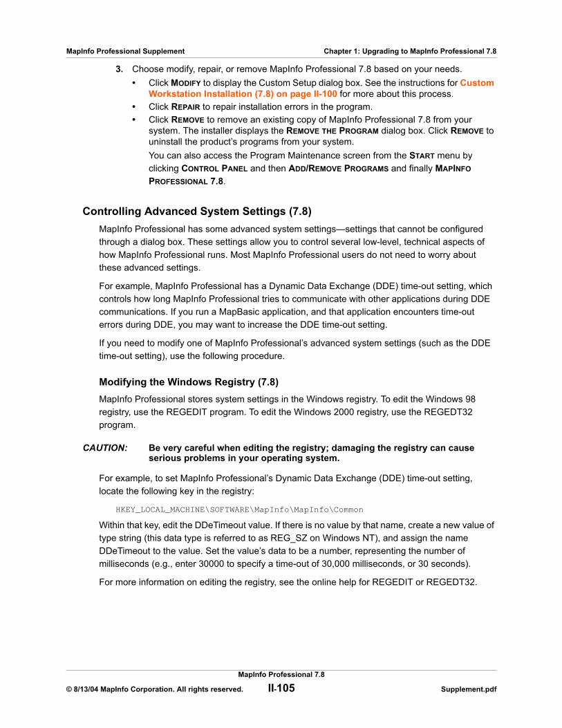
MapInfo Professional Supplement Chapter 1: Upgrading to MapInfo Professional 7.8
3. Choose modify, repair, or remove MapInfo Professional 7.8 based on your needs. • Click MODIFY to display the Custom Setup dialog box. See the instructions for Custom
Workstation Installation (7.8) on page II-100 for more about this process.• Click REPAIR to repair installation errors in the program.• Click REMOVE to remove an existing copy of MapInfo Professional 7.8 from your
system. The installer displays the REMOVE THE PROGRAM dialog box. Click REMOVE to uninstall the product’s programs from your system.You can also access the Program Maintenance screen from the START menu by clicking CONTROL PANEL and then ADD/REMOVE PROGRAMS and finally MAPINFO PROFESSIONAL 7.8.
Controlling Advanced System Settings (7.8)MapInfo Professional has some advanced system settings—settings that cannot be configured through a dialog box. These settings allow you to control several low-level, technical aspects of how MapInfo Professional runs. Most MapInfo Professional users do not need to worry about these advanced settings.
For example, MapInfo Professional has a Dynamic Data Exchange (DDE) time-out setting, which controls how long MapInfo Professional tries to communicate with other applications during DDE communications. If you run a MapBasic application, and that application encounters time-out errors during DDE, you may want to increase the DDE time-out setting.
If you need to modify one of MapInfo Professional’s advanced system settings (such as the DDE time-out setting), use the following procedure.
Modifying the Windows Registry (7.8)MapInfo Professional stores system settings in the Windows registry. To edit the Windows 98 registry, use the REGEDIT program. To edit the Windows 2000 registry, use the REGEDT32 program.
CAUTION: Be very careful when editing the registry; damaging the registry can cause serious problems in your operating system.
For example, to set MapInfo Professional’s Dynamic Data Exchange (DDE) time-out setting, locate the following key in the registry:
HKEY_LOCAL_MACHINE\SOFTWARE\MapInfo\MapInfo\Common
Within that key, edit the DDeTimeout value. If there is no value by that name, create a new value of type string (this data type is referred to as REG_SZ on Windows NT), and assign the name DDeTimeout to the value. Set the value’s data to be a number, representing the number of milliseconds (e.g., enter 30000 to specify a time-out of 30,000 milliseconds, or 30 seconds).
For more information on editing the registry, see the online help for REGEDIT or REGEDT32.
MapInfo Professional 7.8
© 8/13/04 MapInfo Corporation. All rights reserved. II-105 Supplement.pdf
MapInfo Professional Supplement Chapter 1: Upgrading to MapInfo Professional 7.8
Descriptions of Advanced Registry Settings (7.8)This section describes advanced settings that are stored in the registry.
DDeTimeout = numberThis setting controls MapInfo Professional’s time-out setting in DDE conversations where MapInfo Professional is the client (the application that initiates a conversation). The number represents milliseconds. The default value is 10,000 milliseconds (ten seconds). If you run a MapBasic application that attempts to initiate a DDE conversation, but the conversation fails because the server application does not respond within the time-out period, you may need to increase the DDeTimeout number.
OffscreenBitmap = numberThe number is 0 (zero) or 1 (one). A value of 1 (the default) indicates that MapInfo Professional will process off-screen bitmaps when drawing a map. This means that if you cover a Map window, and then bring the Map window to the front again, the map redraws instantly. If you set this setting to zero, MapInfo Professional will not process off-screen bitmaps. This means that when you bring a Map window to the front, you may have to wait as MapInfo Professional redraws the map.
If you are using a video driver that is uncommon or buggy, and if you encounter video problems with Map windows, you may be able to eliminate those problems by setting the OffscreenBitmap number to 0.
MaxFiles = numberThis setting must be an integer from 10 to 100, indicating how many files MapInfo Professional can open simultaneously. This setting does not limit the number of tables you can open, but it does limit the number of tables you can edit at one time (the number of tables that have unsaved edits). The default value is 29. If you need to work with more files simultaneously, set number to 100.
MaxORACLETILES = numberA value from 0 = unlimited tiles to infinity.
Improving Performance for MapInfo Professional 7.8To improve MapInfo Professional’s performance, increase the speed of the processor in the machine. A video accelerator card will increase the speed of the redraw. It will not speed up the initial draw of the map, but all subsequent redraws will be faster. A faster disk cache will also improve performance, as will adding memory.
Controlling the Location of Application Data Files During Installation (7.8)By default, the setup program for MapInfo Professional installs application data files to locations that make sense for the typical user. After installing the product, the user is free to move one or more of the application data files to another predefined location and MapInfo Professional will find that file. For example, the administrator of a machine might move MAPINFOW.PEN from the per user area (its default location) into the install directory so all users on that machine will share the same set of pens.
For IT personnel responsible for a large number of MapInfo Professional installs it is not practical to manually move application data files to realize the desired configuration.
MapInfo Professional 7.8
© 8/13/04 MapInfo Corporation. All rights reserved. II-106 Supplement.pdf

MapInfo Professional Supplement Chapter 1: Upgrading to MapInfo Professional 7.8
To solve this problem we have developed a solution that allows IT personnel to specify the location of application data files by creating a setting file called MODE.INI prior to installing MapInfo Professional.
1. Copy the installation files to a read-write location.2. Create a MODE.INI file in the root directory of the installer.
3. Open MODE.INI into any text editor.4. Edit MODE.INI, modifying the code associated with the application data file/folder whose
location you wish to change.5. Install MapInfo Professional.
The following is a list of predefined locations for application data files supported by MapInfo Professional, and the corresponding numeric code to be used in MODE.INI.
The following is a list of application data files/groups and their default locations:
MODE. INI File ExampleCreate a text file with the following syntax:
GraphSupport = 3CustSymb = 1ThmTmplt = 1MAPINFOW.CLR = 1MAPINFOW.FNT = 1
Code Description Location
1 per user, roaming <Current User>\Application Data
2 per user, not roaming <Current User>\Local Settings\Application Data
3 per machine <All Users>\Application Data
4 program directory <Install Dir>
Filename Default Location
MAPINFOW.CLR per user, roaming
MAPINFOW.PEN per user, roaming
MAPINFOW.FNT per user, roaming
MAPINFOW.ABB program directory
MAPINFOW.PRJ program directory
MAPINFOW.MNU program directory
CustSymb per user, roaming
ThmTmplt per user, roaming
GraphSupport per machine
MapInfo Professional 7.8
© 8/13/04 MapInfo Corporation. All rights reserved. II-107 Supplement.pdf
MapInfo Professional Supplement Chapter 1: Upgrading to MapInfo Professional 7.8
MAPINFOW.PEN = 1MAPINFOW.ABB = 4MAPINFOW.PRJ = 4MAPINFOW.MNU = 4
Installing Data To help you get started, MapInfo provides you with some United States-based and world-wide maps you can use as a background to your data. Use these instructions to install this free data.
To install the free data provided with MapInfo Professional 7.8:
1. Choose INSTALL PRODUCTS from the CD Browser.2. Choose FREE DATA to display the MapInfo Professional Data screen. In this screen, you
can also review the data specifications, access new data over the web and learn about what data is available from MapInfo Corporation.
3. Choose INSTALL FREE DATA. The Welcome screen displays. 4. Choose NEXT to continue. The License Information screen displays. 5. Choose YES to accept the terms of the agreement and to continue the installation process.
The Choose Destination Location screen displays. 6. Select the product for which you will be installing the data. Select one of the following:
• MapInfo Professional • MapInfo Run TimeClick NEXT to continue.
7. Specify the directory where the data will be installed. Use the Browse button to select a directory if necessary or accept the default directory. Click NEXT to continue.
8. Choose one of these options: • CUSTOM INSTALL: Choose which datasets to install. Select the check box beside each
dataset you want to install. The size of each dataset displays, as well as space required and space available. To see the subcomponents of the data you selected, click CHANGE.
• TYPICAL INSTALL: Install all datasets. Choose NEXT to continue. Respond YES to the “Would you like setup to display workspace Icons” prompt if you want to create an icon for each data set you choose.
9. The Select Program Folder screen displays if you chose to set up Workspace icons. Select the program folder where the icons will be created. Choose NEXT.
10. The Start Copying Files screen displays. Review the selections you have chosen and click BACK to return to any screen to change your selections. When you are ready to begin the installation, click NEXT.
11. The Setup Complete dialog box displays; click FINISH.
Getting More DataTo learn more about our data products, click the GET MORE DATA option in the MapInfo Professional Data screen during the Data Installation process or click MAPINFO DATA PRODUCTS ON THE WEB in the Help Menu. If you have a Browser installed, you will be automatically connected
MapInfo Professional 7.8
© 8/13/04 MapInfo Corporation. All rights reserved. II-108 Supplement.pdf

MapInfo Professional Supplement Chapter 1: Upgrading to MapInfo Professional 7.8
to MapInfo Corporation’s web site, where we provide detailed information about MapInfo’s World Wide Data Products. We have over 350 data products to choose from—products that provide both reliable and current information.
Installing Related Programs, Hardware, and Resources (7.8)This section contains the instructions for installing the ECW Compressor, the MetaData Browser, the Blue Marble GPS, and the documentation associated with MapInfo Professional. We also include information about the Microsoft Intellimouse and how to use it.
Installing ECW Compressor (7.8)The ECW raster handler allows you to open and display raster images compressed in the ECW format. We recommend that you exit all Windows programs before installing.
1. Choose INSTALL PRODUCTS from the MapInfo Professional 7.8 CD Browser.2. Choose ECW COMPRESSOR. The Welcome screen displays. Choose NEXT to continue the
installation process.3. The Software License screen displays. Choose YES to accept the terms of the agreement
and to continue the installation process.4. The Choose Destination Location screen displays. Specify the directory where ECW
Compressor will be installed. 5. The Select Program Folder screen displays. Select a folder. Choose NEXT to continue. 6. The Setup Complete screen displays: choose to display the ReadMe file and/or create a
shortcut on your desktop. Choose FINISH.
Installing Metadata Browser (7.8)The Metadata Browser allows you to search data clearinghouse web sites for data products that meet your geographic analysis needs. We recommend that you exit all Windows programs before installing Metadata Browser.
1. Choose INSTALL PRODUCTS from the MapInfo Professional 7.8 CD Browser.2. Choose METADATA BROWSER; the Introduction screen displays. 3. Choose NEXT to continue the installation process. The License Agreement screen
displays. 4. Choose YES to accept the terms of the agreement and to continue the installation
process. The Choose Install Folder screen displays. 5. Specify the directory where Metadata Browser will be installed. Select CHOOSE to display a
list of directories.6. Choose the Shortcut location. You have the option to put the icon in a new group, into the
MapInfo group, in the Start menu, on the Desktop, or to display no icon. 7. Click INSTALL to begin the installation.8. After installation is complete, select DONE.
MapInfo Professional 7.8
© 8/13/04 MapInfo Corporation. All rights reserved. II-109 Supplement.pdf

MapInfo Professional Supplement Chapter 1: Upgrading to MapInfo Professional 7.8
Using the Microsoft IntelliMouse™ to Move Around the Windows (7.8)MapInfo Professional 7.8 supports the Microsoft IntelliMouse™ as follows:
Document Scrolling: In the Map, Layout, Browser, and MapBasic windows, hold down the CONTROL key and move the wheel to scroll the document vertically; the effect is the same as clicking on the arrow at the end of the scroll bar.
Document Panning: In the Map and Browser windows, hold down the wheel button on the IntelliMouse™ and move the mouse to pan the document. Release the button to end the panning. There are three panning speeds. The speed of the panning is based on the cursor’s distance from the starting point, indicated by the origin mark. In the Map window, the distance moved at each speed is a percentage of the zoom distance.
For example, the amount to move at slow speed is. 005 * ZoomDistance, medium speed is. 01 * ZoomDistance, and super speed is .1 * ZoomDistance. In the Browser, the window is scrolled by 1, 3, and 7 lines or columns for slow, medium and super speeds. When the cursor is within 15 pixels of the starting point, there is no panning.
AutoScroll: In the Map and Browser windows, click and release the wheel button to activate AutoScroll. When the mouse cursor is moved away from the starting point the document starts to scroll in whatever direction you move the mouse. When the cursor is returned to the starting point, scrolling stops. AutoScroll is turned off by any mouse click or key stroke. AutoScroll is also turned off when MapInfo Professional loses the focus, for example, when you ALT-TAB to another application.
Zoom: In the Map and Layout windows, move the wheel forward to zoom in on the document. Roll back the mouse wheel to zoom out on the document. The wheel has a series of settings; each “click” is the same as one click with a zoom tool. The mouse wheel does not recenter the view. There are other keyboard commands that allow you to zoom in and out more precisely. Review the MapInfo Professional 7.8 User’s Guide (Unabridged) on your MapInfo Professional 7.8 Installation CD for more information.
Installing Global Positioning Software (GPS) (7.8)To install Global Positioning Software from Blue Marble:
1. From the CD menu, click INSTALL PRODUCTS and then FREE UTILITIES.2. Click INSTALL GPS SUPPORT. You will be prompted to exit all applications before installing.
Choose OK.3. The MapInfo Special Edition dialog box displays. Choose OK.4. The Select Destination Location screen displays. Specify the directory where GPS will be
installed.5. The Software License screen displays. Choose YES to accept the terms of the agreement
and to continue the installation process.6. The Add to the Start Menu dialog box displays: click YES to add a shortcut to the START
menu.7. The ReadMe displays; choose OK to exit the ReadMe.
MapInfo Professional 7.8
© 8/13/04 MapInfo Corporation. All rights reserved. II-110 Supplement.pdf
MapInfo Professional Supplement Chapter 1: Upgrading to MapInfo Professional 7.8
Installing the Online ReferencesMapInfo Professional 7.8 provides the following online reference documents: MapInfo Professional Supplement, MapBasic Reference Guide, Crystal Reports User’s Guide, ArcLink, and EasyLoader documentation, as well as the Adobe Acrobat Reader.
To install the documentation locally:
1. Install the Acrobat Reader.2. Copy the files from the [CD_ROM]:\PDF_DOCS folder to a local directory.3. From Windows Explorer, double-click any of the PDF files to automatically launch the
Acrobat Reader and the online book.
Note: If you have any questions about the use of the Acrobat Reader, contact Adobe support at www.Adobe.com.
Troubleshooting your InstallationThe Installer must be run from a drive with a letter such as G: and not from an explicit UNC path. For example, you might have the MapInfo Professional CD in your computer as USERSPC. Other users may share this device as USERSPC; however, it would not contain a drive letter. The MapInfo Professional Installation program requires a drive letter. To remedy this situation:
1. Right-click the shared directory or CD-ROM and select MAP NETWORK DRIVE. 2. Choose a drive letter to map. 3. Run the Installation Program again from the newly mapped drive letter.
Removing MapInfo Professional 7.8 from your System using Control PanelRemove MapInfo Professional 7.8 by accessing the CD Browser, Program Maintenance screen, or by choosing the Add/Remove Programs option from the Control Panel in Windows, 98, 2000, Windows NT or Windows XP.
Removing MapInfo Professional 7.8 from your System using the CD BrowserTo uninstall MapInfo Professional 7.8:
1. Choose INSTALL PRODUCTS from the CD Browser.2. Choose MAPINFO PROFESSIONAL. The Welcome screen displays. Choose NEXT.3. The Program Maintenance Screen displays. Choose REMOVE.
MapInfo Professional 7.8
© 8/13/04 MapInfo Corporation. All rights reserved. II-111 Supplement.pdf

2
What’s New in MapInfo Professional 7.8Thank you for upgrading to the most advanced computer mapping product in the MapInfo family! As the field of computer mapping continues to expand, MapInfo leads the way with new products that are designed to fulfill your computer mapping needs from the most basic to the most specialized with MapMarker, our premier address matching product.
Sections in this Chapter:
New Major Features of MapInfo Professional 7.8 . . . . . . . . . II-113Raster Enhancements . . . . . . . . . . . . . . . . . . . . . . . . . . . . . . . II-129Mapping Enhancements . . . . . . . . . . . . . . . . . . . . . . . . . . . . . II-1303D Enhancements. . . . . . . . . . . . . . . . . . . . . . . . . . . . . . . . . . . II-135Datum Enhancements . . . . . . . . . . . . . . . . . . . . . . . . . . . . . . . II-135Printing Enhancements . . . . . . . . . . . . . . . . . . . . . . . . . . . . . . II-137Database Enhancements . . . . . . . . . . . . . . . . . . . . . . . . . . . . . II-138Tool Enhancements . . . . . . . . . . . . . . . . . . . . . . . . . . . . . . . . . II-139Documentation Enhancements . . . . . . . . . . . . . . . . . . . . . . . . II-149Licensing Enhancements . . . . . . . . . . . . . . . . . . . . . . . . . . . . II-150MapBasic Enhancements . . . . . . . . . . . . . . . . . . . . . . . . . . . . II-151

MapInfo Professional Supplement Chapter 2: What’s New in MapInfo Professional 7.8
New Major Features of MapInfo Professional 7.8
There are several exciting new features in Microsoft XP Logo Certified MapInfo Professional 7.8. These innovations are the results of requests from many of our customers and are in response to changes and growth in the computer mapping industry. We are very excited to bring these changes to you in this release.
Adding WFS Client SupportMapInfo Professional 7.8 provides a Web Feature Service (WFS) client to retrieve geospatial GML (Geography Markup Language)2 data using HTTP GET and HTTP POST requests over the Internet or through a private intranet. The WFS client was developed in accordance with the 1.0.0 OpenGIS® Web Feature Service Implementation Specification, which is available online:http://www.opengis.org/docs/02-058.pdf
WFS is similar to WMS (Web Mapping Service), in that both can provide geographic data via the Internet. But while a WMS server provides raster maps, a WFS server provides raw coordinate data that the client uses to produce a map.
A WFS is similar to a Web Map Service, which allows a client to overlay map images from multiple services over the Internet or through a local intranet. For more details on Web Map Services, see the MapInfo Professional v7.8 User’s Guide.
Note: The MapInfo WFS client has been developed in accordance with OGC WFS Specification 1.0.0. Using this client you cannot retrieve data from sites that are compliant with earlier or later versions of the OGC specification.
This version of the WFS client supports GML2 (OGC GML V2.1.1). The OGS WFS Specification states that all servers should support GML2, but may also support other formats. The server provides information on the formats available, and the client makes the request for the data in the format it can use. If the server does not support GML2, it will not be supported by the MapInfo WFS client.
GML2 does not contain any style information. You can provide style information to associate with a particular WFS table.
A WFS request contains a description of query operations that can be applied to one or more features. The client generates the request and posts it to a WFS using HTTP. The web feature server then reads and executes the request.
The GetCapabilities operation queries the WFS server for capabilities. Then the MapInfo Professional WFS client can generate a query appropriate for the WFS server and table.
Each table in the WFS server can result in a single MapInfo table. The mapping is always 1-to-1 (unlike WMS, which is many-to-1).
The TAB file retrieved from a WFS server resembles a read-only DBMS linked table. It contains a MAP file and a DAT file, and acts like a read-only native table. Information is stored so that the table can be refreshed from the WFS server.
MapInfo Professional 7.8
© 8/13/04 MapInfo Corporation. All rights reserved. II-113 Supplement.pdf

MapInfo Professional Supplement Chapter 2: What’s New in MapInfo Professional 7.8
The sequence of actions can be summarized as follows:
1. After sending a GetCapabilities request to a WFS server, the server returns a list of WFS layers (FeatureTypes) that it can provide.
2. The user picks a WFS layer to fetch from the server, MapInfo Pro then sends a DescribeFeatureType request to the server. This response is an XML schema that describes the feature.
3. The user can then select which columns and/or rows to fetch.4. MapInfo Pro sends a GetFeature request to the WFS. If the user did not select a subset of
columns, all columns will be requested by default.5. The response is a GML document containing the feature collection. Each feature
represents one “record” in the MapInfo table.
MapInfo has added a list of WFS servers to the client to help you get started in using this new functionality.
Note: Since the data you retrieve using the WFS is remote, it may change from time to time. You can refetch your WFS data manually using the refresh process. See Refreshing a WFS Layer on page II-120 for these instructions.
Accessing Web Feature ServicesIf a MapInfo WFS table is open, the user interface automatically enables the refresh process. During the refresh process, users can not change the query that is sent to the WFS server. The data will be refetched from the server using the original query. This refreshed information can then be saved to the table.
Note: You must have a working Internet connection whenever you retrieve WFS data.
Opening a Web Feature ServiceTo open a Web Feature Service:
1. On the FILE menu, select OPEN WEB SERVICE > OPEN WFS or click to open the WFS SERVER MAP PROPERTIES dialog box. This opens the default WFS server.
MapInfo Professional 7.8
© 8/13/04 MapInfo Corporation. All rights reserved. II-114 Supplement.pdf
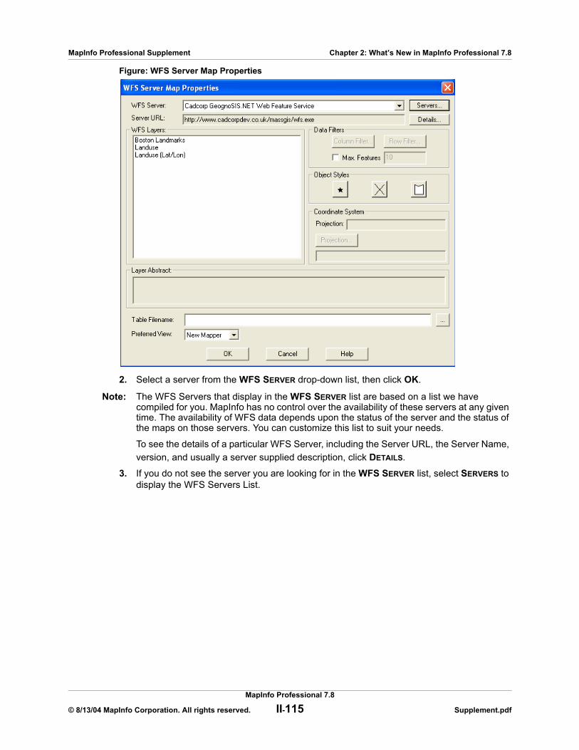
MapInfo Professional Supplement Chapter 2: What’s New in MapInfo Professional 7.8
Figure: WFS Server Map Properties
2. Select a server from the WFS SERVER drop-down list, then click OK.
Note: The WFS Servers that display in the WFS SERVER list are based on a list we have compiled for you. MapInfo has no control over the availability of these servers at any given time. The availability of WFS data depends upon the status of the server and the status of the maps on those servers. You can customize this list to suit your needs.
To see the details of a particular WFS Server, including the Server URL, the Server Name, version, and usually a server supplied description, click DETAILS.
3. If you do not see the server you are looking for in the WFS SERVER list, select SERVERS to display the WFS Servers List.
MapInfo Professional 7.8
© 8/13/04 MapInfo Corporation. All rights reserved. II-115 Supplement.pdf
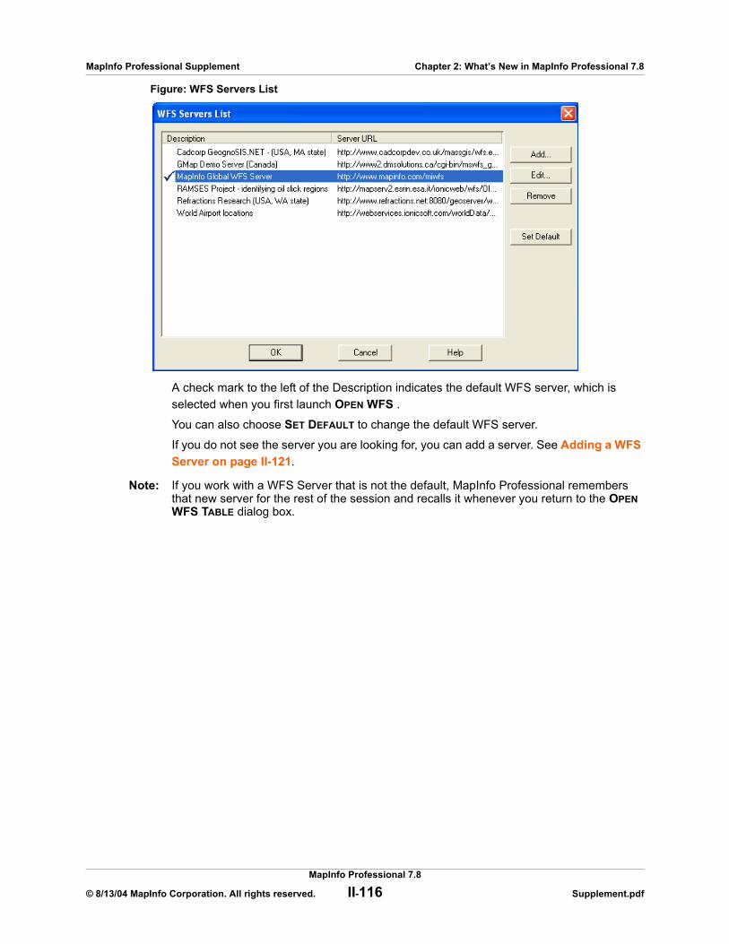
MapInfo Professional Supplement Chapter 2: What’s New in MapInfo Professional 7.8
Figure: WFS Servers List
A check mark to the left of the Description indicates the default WFS server, which is selected when you first launch OPEN WFS .
You can also choose SET DEFAULT to change the default WFS server.
If you do not see the server you are looking for, you can add a server. See Adding a WFS Server on page II-121.
Note: If you work with a WFS Server that is not the default, MapInfo Professional remembers that new server for the rest of the session and recalls it whenever you return to the OPEN WFS TABLE dialog box.
MapInfo Professional 7.8
© 8/13/04 MapInfo Corporation. All rights reserved. II-116 Supplement.pdf
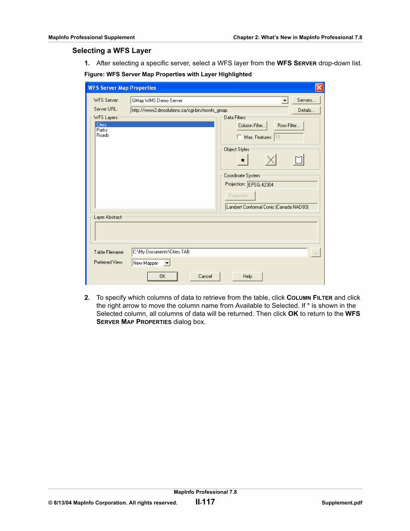
MapInfo Professional Supplement Chapter 2: What’s New in MapInfo Professional 7.8
Selecting a WFS Layer1. After selecting a specific server, select a WFS layer from the WFS SERVER drop-down list.Figure: WFS Server Map Properties with Layer Highlighted
2. To specify which columns of data to retrieve from the table, click COLUMN FILTER and click the right arrow to move the column name from Available to Selected. If * is shown in the Selected column, all columns of data will be returned. Then click OK to return to the WFS SERVER MAP PROPERTIES dialog box.
MapInfo Professional 7.8
© 8/13/04 MapInfo Corporation. All rights reserved. II-117 Supplement.pdf
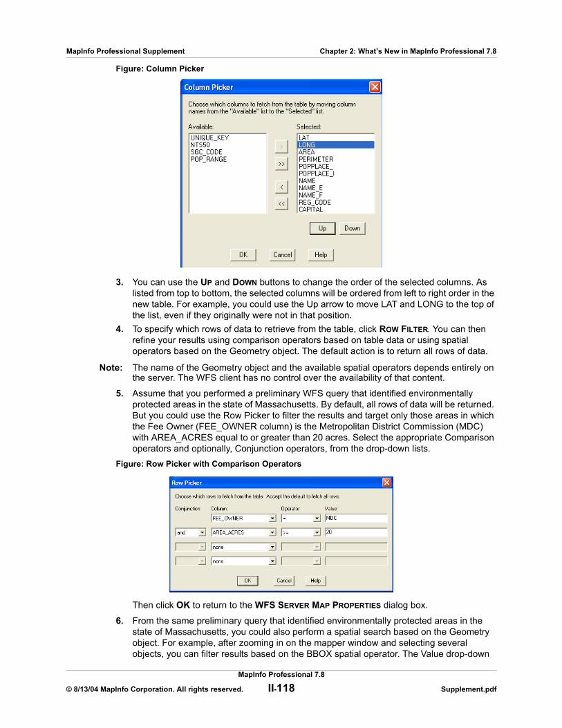
MapInfo Professional Supplement Chapter 2: What’s New in MapInfo Professional 7.8
Figure: Column Picker
3. You can use the UP and DOWN buttons to change the order of the selected columns. As listed from top to bottom, the selected columns will be ordered from left to right order in the new table. For example, you could use the Up arrow to move LAT and LONG to the top of the list, even if they originally were not in that position.
4. To specify which rows of data to retrieve from the table, click ROW FILTER. You can then refine your results using comparison operators based on table data or using spatial operators based on the Geometry object. The default action is to return all rows of data.
Note: The name of the Geometry object and the available spatial operators depends entirely on the server. The WFS client has no control over the availability of that content.
5. Assume that you performed a preliminary WFS query that identified environmentally protected areas in the state of Massachusetts. By default, all rows of data will be returned. But you could use the Row Picker to filter the results and target only those areas in which the Fee Owner (FEE_OWNER column) is the Metropolitan District Commission (MDC) with AREA_ACRES equal to or greater than 20 acres. Select the appropriate Comparison operators and optionally, Conjunction operators, from the drop-down lists.
Figure: Row Picker with Comparison Operators
Then click OK to return to the WFS SERVER MAP PROPERTIES dialog box.
6. From the same preliminary query that identified environmentally protected areas in the state of Massachusetts, you could also perform a spatial search based on the Geometry object. For example, after zooming in on the mapper window and selecting several objects, you can filter results based on the BBOX spatial operator. The Value drop-down
MapInfo Professional 7.8
© 8/13/04 MapInfo Corporation. All rights reserved. II-118 Supplement.pdf

MapInfo Professional Supplement Chapter 2: What’s New in MapInfo Professional 7.8
list always has a choice for ALL and will display CURRENT_MAPPER if one or more windows are open. You will also see a SELECTION choice if one or more objects have been selected from the mapper or browser window.
Note: Note that the name of the Geometry object (for example, GEOM) and the available spatial operators depends on the server.
Figure: Row Picker with Spatial Operators
7. Click OK to return to the WFS SERVER MAP PROPERTIES dialog box. If this checkbox is not selected, all features (as defined by ROW FILTER) will be returned.
8. Select an appropriate file name from the TABLE FILENAME entry box. See Handling Retrieved WFS Data on page II-120 for detailed information on specifying file names and folders for saved tables.
9. From the PREFERRED VIEW drop-down list in the WFS SERVER MAP PROPERTIES dialog box, select the preferred view for the returned results. New Mapper is the default. Then click OK to generate results. The results (filtered by selected column and row names) are displayed in the specified window.
Controlling WFS Maximum FeaturesTo limit the number of features returned by the WFS server, select the Max Features checkbox in the WFS Server Map Properties dialog box and enter a number. By limiting the number of downloaded features, it may take less time to download and display a table than it would for downloading the entire table. This may allow you to quickly judge the value of the data. However, you cannot control which features are downloaded.
Note: While, the OGS WFS Specification mandates that WFS servers must support Max Features, some WFS servers seem not to support it.
Changing a WFS Coordinate SystemThe PROJECTIONS button is enabled only if the projection provided by the WFS server cannot be properly interpreted by the WFS client. If the projection provided by the WFS server can be properly understood, this button will be disabled and can be ignored.
If the PROJECTIONS button is active, you must use it to specify a known projection from the list of supported projections so that the GML2 image can be imported correctly. Select the coordinate system that you believe matches to the data returned by the server.
1. After selecting a layer in the WFS SERVER PROPERTIES MAP dialog box, click PROJECTION (if the button is enabled) to display the CHOOSE PROJECTIONS dialog box.
MapInfo Professional 7.8
© 8/13/04 MapInfo Corporation. All rights reserved. II-119 Supplement.pdf
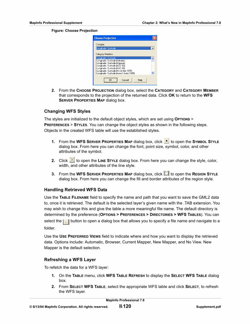
MapInfo Professional Supplement Chapter 2: What’s New in MapInfo Professional 7.8
Figure: Choose Projection
2. From the CHOOSE PROJECTION dialog box, select the CATEGORY and CATEGORY MEMBER that corresponds to the projection of the returned data. Click OK to return to the WFS SERVER PROPERTIES MAP dialog box.
Changing WFS StylesThe styles are initialized to the default object styles, which are set using OPTIONS > PREFERENCES > STYLES. You can change the object styles as shown in the following steps. Objects in the created WFS table will use the established styles.
1. From the WFS SERVER PROPERTIES MAP dialog box, click to open the SYMBOL STYLE dialog box. From here you can change the font, point size, symbol, color, and other attributes of the symbol.
2. Click to open the LINE STYLE dialog box. From here you can change the style, color, width, and other attributes of the line style.
3. From the WFS SERVER PROPERTIES MAP dialog box, click to open the REGION STYLE dialog box. From here you can change the fill and border attributes of the region style.
Handling Retrieved WFS DataUse the TABLE FILENAME field to specify the name and path that you want to save the GML2 data to, once it is retrieved. The default is the selected layer’s given name with the .TAB extension. You may wish to change this and give the table a more meaningful file name. The default directory is determined by the preference (OPTIONS > PREFERENCES > DIRECTORIES > WFS TABLES). You can select the button to open a dialog box that allows you to specify a file name and navigate to a
folder.
Use the USE PREFERRED VIEWS field to indicate where and how you want to display the retrieved data. Options include: Automatic, Browser, Current Mapper, New Mapper, and No View. New Mapper is the default selection.
Refreshing a WFS LayerTo refetch the data for a WFS layer:
1. On the TABLE menu, click WFS TABLE REFRESH to display the SELECT WFS TABLE dialog box.
2. From SELECT WFS TABLE, select the appropriate WFS table and click SELECT, to refresh the WFS layer.
MapInfo Professional 7.8
© 8/13/04 MapInfo Corporation. All rights reserved. II-120 Supplement.pdf

MapInfo Professional Supplement Chapter 2: What’s New in MapInfo Professional 7.8
3. Click OK to exit the dialog box.
Adding a WFS ServerIf you do not see the server you are looking for in the WFS SERVERS LIST dialog box, you can add a server.
Note: The servers we display in this docum;ent are some examples of servers that worked in our laboratory tests. Please contact your service provider if you have difficulties with WFS server access.
1. From the WFS SERVERS LIST dialog box, click ADD to display the WFS SERVER INFORMATION dialog box. This same dialog box appears when you click the EDIT button in the WFS SERVERS LIST.
Figure: WFS Server Information.
2. Type the URL you want to add in the SERVER URL field. Click TEST URL to ensure that MapInfo Professional can find the server. Click GET DESCRIPTION to get the server-provided description, or type in your own description. Click OK to return to the WFS SERVERS LIST dialog box.
3. In the WFS SERVERS LIST dialog box, click SET DEFAULT to select a default server in the list. The default server will be selected the first time you open the WFS TABLE dialog box. When you set a default WFS server, a check mark displays beside it. If you do not select a default server, MapInfo Professional displays the first server in the list when you begin your WFS Server session.
4. To edit a WFS server, select the server from the WFS SERVERS LIST dialog box and click EDIT to open the WFS Servers Information dialog box. From here you can test the URL and get detailed information on the server.
5. To remove a WFS server, select the server from the WFS SERVERS LIST dialog box and click REMOVE. This removes the server from the list.
6. When you have completed your work in the WFS SERVERS LIST, click OK to return to the Open WFS SERVER MAP PROPERTIES dialog box.
Controlling WFS Server Timeout ValuesYou can set several optional registry entries to control how long the WFS client will attempt to connect to the server before timing out. These are optional entries, and if not set, the indicated default values are used. Server timeout values can not be set through the MapInfo application interface.
These registry entries are DWORD values, with the decimal value representing the number of seconds for the timeout. The registry entries reside in:
HKEY_LOCAL_MACHINE\SOFTWARE\Mapinfo\MapInfo\Common
MapInfo Professional 7.8
© 8/13/04 MapInfo Corporation. All rights reserved. II-121 Supplement.pdf

MapInfo Professional Supplement Chapter 2: What’s New in MapInfo Professional 7.8
WFS-Related Error MessagesThe MapInfo Pro WFS client will return appropriate error messages. Data returned to the WFS client depends on the availability and status of the WFS server and the characteristics and status of the maps on the WFS server. These conditions are beyond the control of MapInfo.
The following table lists and explains WFS-related error messages.
WFS Server Timeout Entries
Registry Entry Description Default Value
WFSConnectTimeout Connect Timeout - the amount of time allowed to establish an Internet connection request. If the request takes longer than this value, a timeout occurs.
60 seconds
WFSSendTimeout Send Timeout - the amount of time allowed to send an Internet request. If the request takes longer than this value, a timeout occurs.
60 seconds
WFSReceiveTimeout Receive Timeout - the amount of time allowed to begin to receive a response from a request. The download can take longer than the timeout, but the response has to occur within the timeout set-ting.
300 seconds
WFS-Related Error Messages
Error Message Description and Explanation of Message
The WFS Server issued the following exception: <message from server>
The raw data following the colon is transmitted by the WFS server. This may help you analyze the problem.The WFS server generated an error. For clarification, contact the service provider of the WFS server.
The following error was issued while attempting to access the WFS server: <message from server>
There could be a problem with the URL, the server may not be available, or it may have timed out.
The WFS Server returned no data in response to the request.
MapInfo issued a service request, but nothing was received from the server.
Unable to retrieve capabilities from the WFS Server.
The server did not return a list of FeatureTypes in response to the GetCapabilities request. This message usually appears paired with another message in the same window.
MapInfo Professional 7.8
© 8/13/04 MapInfo Corporation. All rights reserved. II-122 Supplement.pdf
MapInfo Professional Supplement Chapter 2: What’s New in MapInfo Professional 7.8
The WFS Server returned HTML data rather than the requested format. The specified address may not be a WFS Server or the server could not process the request: <message from server>
The raw data following the colon is transmitted by the WFS server. This may help you analyze the problem.The server you are accessing may not be a WFS server. You may see this message after accessing a WFS server and seeing a list of WFS layers. This can occur because the Capabilities document provided by the server may contain additional URLs that redirect you to another server (not the one you explicitly selected). That “redirected” server may be down or have another problem.
The WFS Server returned data which was neither in the requested format nor a recognized WFS service exception: <message from server>
The raw data following the colon is transmitted by the WFS server. This may help you analyze the problem.The exception message from the server could not be understood. For example, the exception message may not have been in XML format.
Error accessing temporary file. It is possible that your disk is full or you might have deleted the temp file while MapInfo Pro was running.
In response to a DescribeFeatureType request, the WFS Server returned an invalid feature type.
MapInfo could not interpret the schema returned by the server. This message is usually preceded by either another MapInfo error message or raw data transmitted by the WFS server. This may help you analyze the problem.
Unable to read WFS Table Description XML file.
The most likely cause of this error, is that the user edited the XML file that was created by MapInfo.
Unable to retrieve WFS Server GetFeature.
This message is usually preceded by either another MapInfo error message or raw data transmitted by the WFS server. This may help you analyze the problem.
An error occurred while processing GML returned from the WFS server.
The server provided GML that MapInfo could not interpret.
The WFS Server returned capabilities in an unsupported versions: <message from server>
The raw data following the colon is transmitted by the WFS server, and identifies the WFS version in the Capabilities document, as reported by the server. This may help you analyze the problem.
The layer is not supported because it has more than one FeatureType.
The MapInfo WFS client expects one FeatureType in the schema. However, the schema returned by the server contained more than one FeatureType.
You need to select a WFS layer. After selecting a server In the WFS Server Map Properties dialog box, you must also select a WFS layer. If you click OK before selecting a WFS layer, you will get this error message.
Error: Unable to communicate with the WFS server while trying to determine the table structure.
This message can appear when pressing the OK button on the WFS Sever Map Properties dialog. This means that the DescribeFeatureType failed.
WFS-Related Error Messages
Error Message Description and Explanation of Message
MapInfo Professional 7.8
© 8/13/04 MapInfo Corporation. All rights reserved. II-123 Supplement.pdf
MapInfo Professional Supplement Chapter 2: What’s New in MapInfo Professional 7.8
Adding GetFeatureInfo Support to Web Map Service
The Info Tool now provides GetFeatureInfo support for Web Map Service (WMS). When you click on the WMS layer with the Info tool, the Info tool window displays information about the features of each layer that you have retrieved from a WMS server.
By default, when you open a WMS layer and add it to a map, it is selectable when it meets the following criteria:
• The WMS server must support GetFeatureInfo.• The WMS server must return GetFeatureInfo data in a format that is supported by MapInfo
Professional. These formats are text/plain and the xml and gml formats returned by MapXtreme® Java edition and MapXtreme® 2004, respectively.
• The WMS servers must specify that at least one of the WMS layers within the WMS table can be queried.
The WMS layer can also be made selectable using the MapBasic statement:
set map layer layer_id selectable on
After making the WMS layer selectable, the Info tool can be used. Information will be returned only from layers that are queryable. The WMS table treeview in the OPEN WMS TABLE and WMS TABLE PROPERTIES dialog boxes display an Information icon next to queryable layers to indicate that the InfoTool will work on those layers.
Please select a supported projection. This message appears if the selected WFS layer has Unsupported Projection, and the user did not select the PROJECTION button to specify a projection.
Error: Unable to create XML file for WFS table.
This message can appear when pressing the OK button on the WFS Sever Map Properties dialog. This means there is a problem creating the XML file used to open a WFS table.
Error: The WFS server does not return data in the required GML2 format.
The user selected a WFS server that does not support GML2 as an output format.
WFS-Related Error Messages
Error Message Description and Explanation of Message
MapInfo Professional 7.8
© 8/13/04 MapInfo Corporation. All rights reserved. II-124 Supplement.pdf
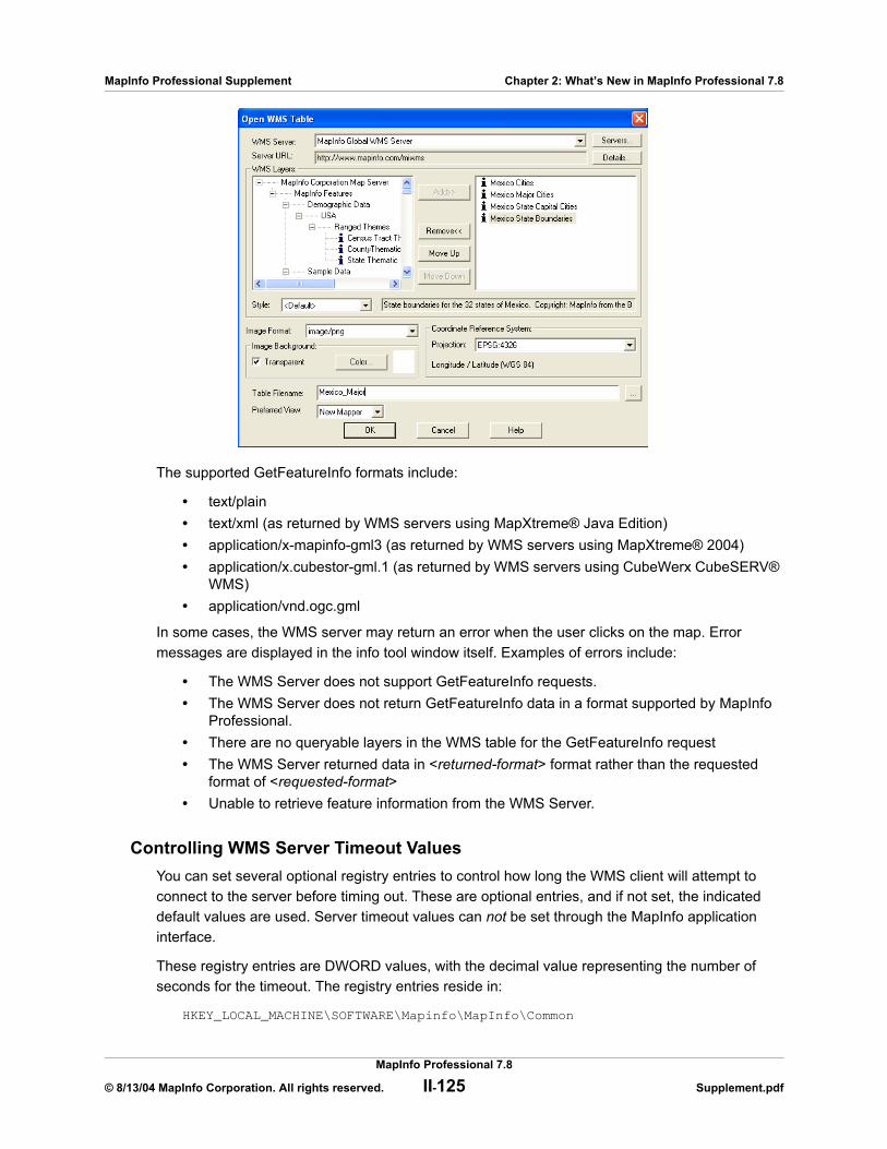
MapInfo Professional Supplement Chapter 2: What’s New in MapInfo Professional 7.8
The supported GetFeatureInfo formats include:
• text/plain• text/xml (as returned by WMS servers using MapXtreme® Java Edition)• application/x-mapinfo-gml3 (as returned by WMS servers using MapXtreme® 2004)• application/x.cubestor-gml.1 (as returned by WMS servers using CubeWerx CubeSERV®
WMS)• application/vnd.ogc.gml
In some cases, the WMS server may return an error when the user clicks on the map. Error messages are displayed in the info tool window itself. Examples of errors include:
• The WMS Server does not support GetFeatureInfo requests.• The WMS Server does not return GetFeatureInfo data in a format supported by MapInfo
Professional.• There are no queryable layers in the WMS table for the GetFeatureInfo request• The WMS Server returned data in <returned-format> format rather than the requested
format of <requested-format>• Unable to retrieve feature information from the WMS Server.
Controlling WMS Server Timeout ValuesYou can set several optional registry entries to control how long the WMS client will attempt to connect to the server before timing out. These are optional entries, and if not set, the indicated default values are used. Server timeout values can not be set through the MapInfo application interface.
These registry entries are DWORD values, with the decimal value representing the number of seconds for the timeout. The registry entries reside in:
HKEY_LOCAL_MACHINE\SOFTWARE\Mapinfo\MapInfo\Common
MapInfo Professional 7.8
© 8/13/04 MapInfo Corporation. All rights reserved. II-125 Supplement.pdf
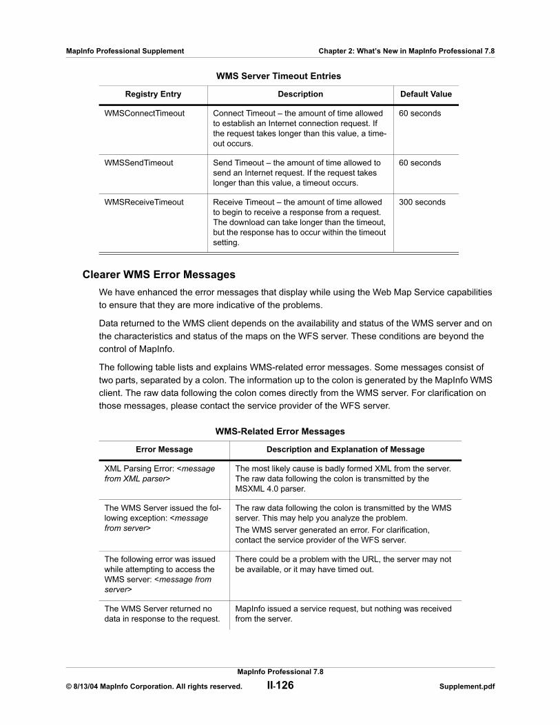
MapInfo Professional Supplement Chapter 2: What’s New in MapInfo Professional 7.8
Clearer WMS Error MessagesWe have enhanced the error messages that display while using the Web Map Service capabilities to ensure that they are more indicative of the problems.
Data returned to the WMS client depends on the availability and status of the WMS server and on the characteristics and status of the maps on the WFS server. These conditions are beyond the control of MapInfo.
The following table lists and explains WMS-related error messages. Some messages consist of two parts, separated by a colon. The information up to the colon is generated by the MapInfo WMS client. The raw data following the colon comes directly from the WMS server. For clarification on those messages, please contact the service provider of the WFS server.
WMS Server Timeout Entries
Registry Entry Description Default Value
WMSConnectTimeout Connect Timeout – the amount of time allowed to establish an Internet connection request. If the request takes longer than this value, a time-out occurs.
60 seconds
WMSSendTimeout Send Timeout – the amount of time allowed to send an Internet request. If the request takes longer than this value, a timeout occurs.
60 seconds
WMSReceiveTimeout Receive Timeout – the amount of time allowed to begin to receive a response from a request. The download can take longer than the timeout, but the response has to occur within the timeout setting.
300 seconds
WMS-Related Error Messages
Error Message Description and Explanation of Message
XML Parsing Error: <message from XML parser>
The most likely cause is badly formed XML from the server. The raw data following the colon is transmitted by the MSXML 4.0 parser.
The WMS Server issued the fol-lowing exception: <message from server>
The raw data following the colon is transmitted by the WMS server. This may help you analyze the problem.The WMS server generated an error. For clarification,contact the service provider of the WFS server.
The following error was issued while attempting to access the WMS server: <message from server>
There could be a problem with the URL, the server may not be available, or it may have timed out.
The WMS Server returned no data in response to the request.
MapInfo issued a service request, but nothing was received from the server.
MapInfo Professional 7.8
© 8/13/04 MapInfo Corporation. All rights reserved. II-126 Supplement.pdf
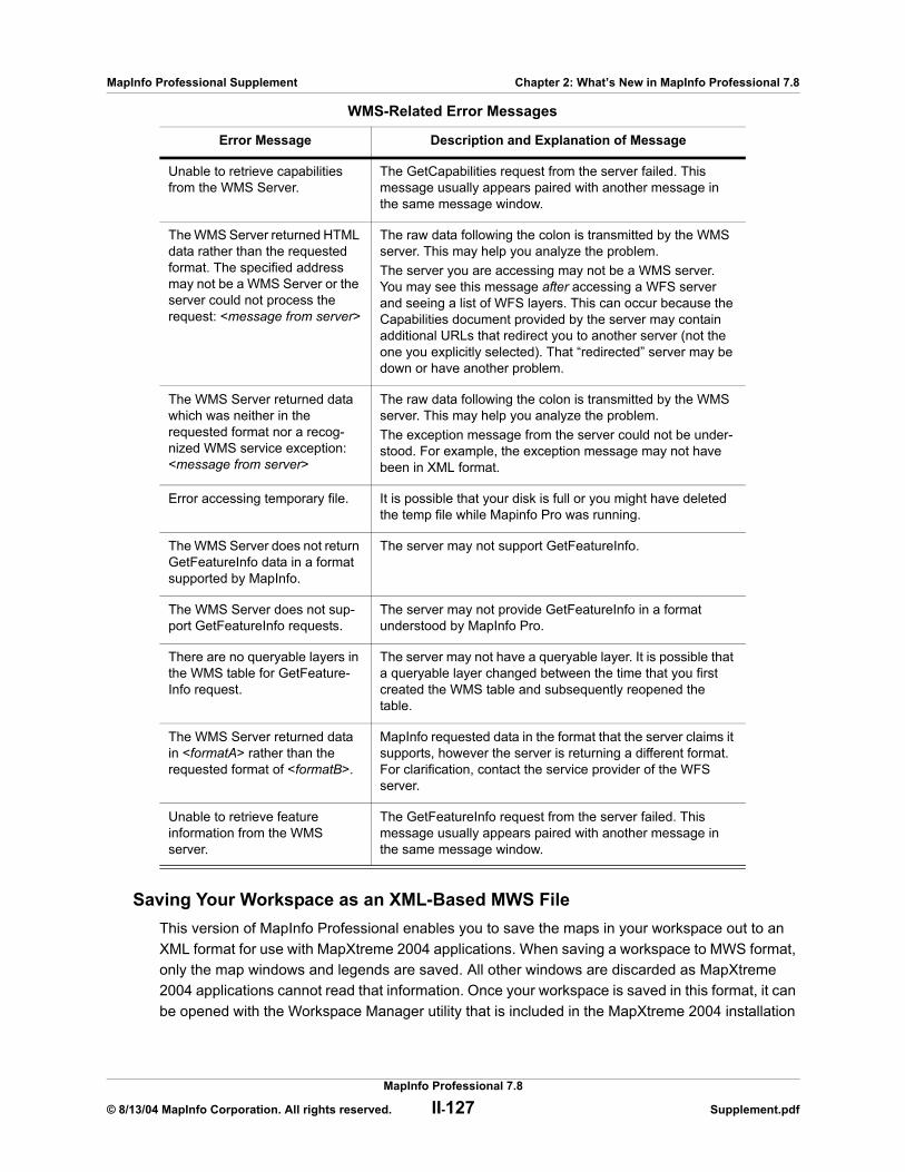
MapInfo Professional Supplement Chapter 2: What’s New in MapInfo Professional 7.8
Saving Your Workspace as an XML-Based MWS FileThis version of MapInfo Professional enables you to save the maps in your workspace out to an XML format for use with MapXtreme 2004 applications. When saving a workspace to MWS format, only the map windows and legends are saved. All other windows are discarded as MapXtreme 2004 applications cannot read that information. Once your workspace is saved in this format, it can be opened with the Workspace Manager utility that is included in the MapXtreme 2004 installation
Unable to retrieve capabilities from the WMS Server.
The GetCapabilities request from the server failed. This message usually appears paired with another message in the same message window.
The WMS Server returned HTML data rather than the requested format. The specified address may not be a WMS Server or the server could not process the request: <message from server>
The raw data following the colon is transmitted by the WMS server. This may help you analyze the problem.The server you are accessing may not be a WMS server. You may see this message after accessing a WFS server and seeing a list of WFS layers. This can occur because the Capabilities document provided by the server may contain additional URLs that redirect you to another server (not the one you explicitly selected). That “redirected” server may be down or have another problem.
The WMS Server returned data which was neither in the requested format nor a recog-nized WMS service exception: <message from server>
The raw data following the colon is transmitted by the WMS server. This may help you analyze the problem.The exception message from the server could not be under-stood. For example, the exception message may not have been in XML format.
Error accessing temporary file. It is possible that your disk is full or you might have deleted the temp file while Mapinfo Pro was running.
The WMS Server does not return GetFeatureInfo data in a format supported by MapInfo.
The server may not support GetFeatureInfo.
The WMS Server does not sup-port GetFeatureInfo requests.
The server may not provide GetFeatureInfo in a format understood by MapInfo Pro.
There are no queryable layers in the WMS table for GetFeature-Info request.
The server may not have a queryable layer. It is possible that a queryable layer changed between the time that you first created the WMS table and subsequently reopened the table.
The WMS Server returned data in <formatA> rather than the requested format of <formatB>.
MapInfo requested data in the format that the server claims it supports, however the server is returning a different format. For clarification, contact the service provider of the WFS server.
Unable to retrieve feature information from the WMS server.
The GetFeatureInfo request from the server failed. This message usually appears paired with another message in the same message window.
WMS-Related Error Messages
Error Message Description and Explanation of Message
MapInfo Professional 7.8
© 8/13/04 MapInfo Corporation. All rights reserved. II-127 Supplement.pdf
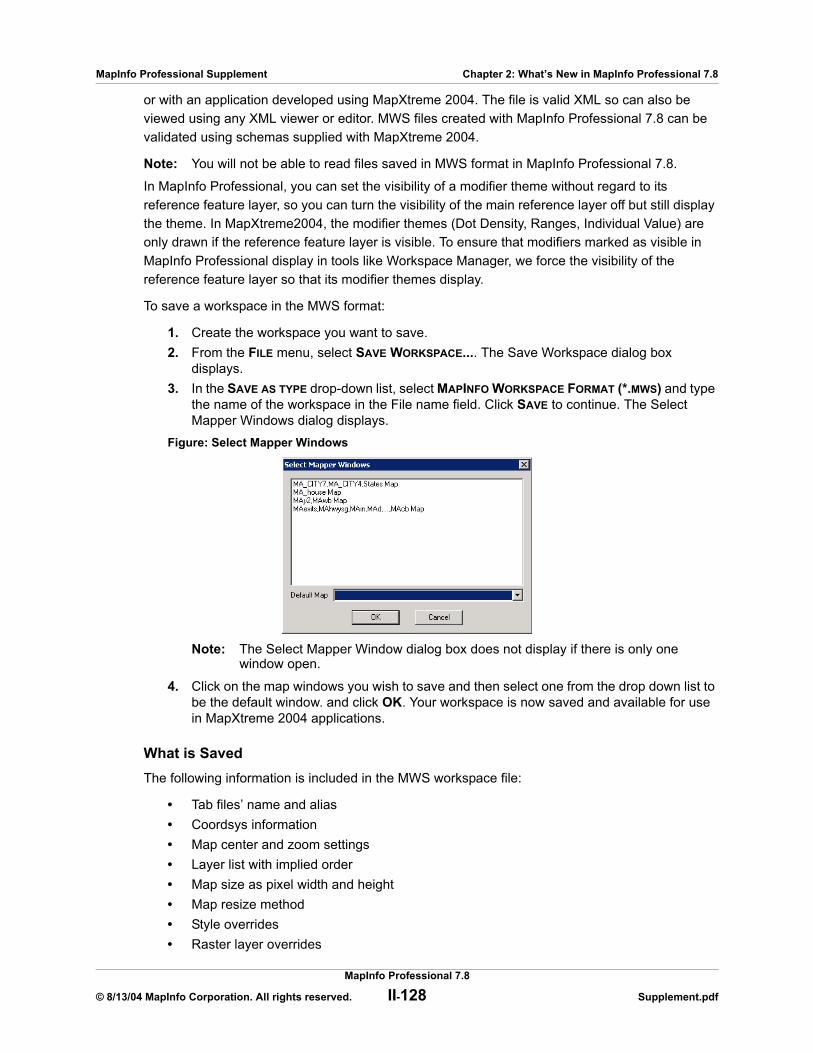
MapInfo Professional Supplement Chapter 2: What’s New in MapInfo Professional 7.8
or with an application developed using MapXtreme 2004. The file is valid XML so can also be viewed using any XML viewer or editor. MWS files created with MapInfo Professional 7.8 can be validated using schemas supplied with MapXtreme 2004.
Note: You will not be able to read files saved in MWS format in MapInfo Professional 7.8.
In MapInfo Professional, you can set the visibility of a modifier theme without regard to its reference feature layer, so you can turn the visibility of the main reference layer off but still display the theme. In MapXtreme2004, the modifier themes (Dot Density, Ranges, Individual Value) are only drawn if the reference feature layer is visible. To ensure that modifiers marked as visible in MapInfo Professional display in tools like Workspace Manager, we force the visibility of the reference feature layer so that its modifier themes display.
To save a workspace in the MWS format:
1. Create the workspace you want to save.2. From the FILE menu, select SAVE WORKSPACE.... The Save Workspace dialog box
displays.3. In the SAVE AS TYPE drop-down list, select MAPINFO WORKSPACE FORMAT (*.MWS) and type
the name of the workspace in the File name field. Click SAVE to continue. The Select Mapper Windows dialog displays.
Figure: Select Mapper Windows
Note: The Select Mapper Window dialog box does not display if there is only one window open.
4. Click on the map windows you wish to save and then select one from the drop down list to be the default window. and click OK. Your workspace is now saved and available for use in MapXtreme 2004 applications.
What is SavedThe following information is included in the MWS workspace file:
• Tab files’ name and alias• Coordsys information• Map center and zoom settings• Layer list with implied order• Map size as pixel width and height• Map resize method• Style overrides• Raster layer overrides
MapInfo Professional 7.8
© 8/13/04 MapInfo Corporation. All rights reserved. II-128 Supplement.pdf

MapInfo Professional Supplement Chapter 2: What’s New in MapInfo Professional 7.8
• Label and label edit information• Individual value themes• Dot density themes• Graduated symbol themes• Bar themes• Range themes• Pie themes• Grid themes as MapXtreme 2004 grid layers with a style override • Themes and label expressions based upon a single attribute column.
What is Not SavedThe following information is not saved in the MWS workspace file:
• Any non-map windows (browsers, charts, redistricters, 3D map windows, Prism maps)• Distance, area, or XY and military grid units• Snap mode, autoscroll, and smart pan settings• Printer setup information• Any table that is based on a query• Any theme that is generated from a complex expression
Note: A complex expression includes any operator or multiple referenced tables.
• Any queries• Export options• Line direction arrows• Whether object nodes are drawn or not• Hot links for labels and objects
Raster Enhancements
We have upgraded the raster handlers in MapInfo Professional to improve the look and performance of your raster files. We have:
• Upgraded the LeadTools to version 13• Upgraded to a newer version of MrSID SDK (3.2), to provide support for MG3 files• Updated the current raster handlers to handle multi-threading; specifically for ECW and
the Government handlers (ADRG, ASRP, CADRG, CIB, NITF)
Get a Clear Picture of your U.S. Data with the AirPhotoUSA Map Handler 4.0 for MapInfo Professional. AirPhotoUSA provides raster images at different elevations for particular areas in the United States. The AirPhotoUSA map handler allows MapInfo users to open and display the imagery contained in AirPhotoUSA Map files as a layer in MapInfo. These files are treated just like any other raster file in MapInfo Professional. The MAPINFOW.PRJ file has been updated to accommodate the AirPhotoUSA enhancements.
MapInfo Professional 7.8
© 8/13/04 MapInfo Corporation. All rights reserved. II-129 Supplement.pdf

MapInfo Professional Supplement Chapter 2: What’s New in MapInfo Professional 7.8
Mapping Enhancements
Removed: 256 Character Limit in Text BoxesMapInfo Layout or Mapper windows, which were previously limited to 256 characters, can now contain a maximum of 2047 characters. Text object rotation is restricted to under 256 bytes. Labels, however, are still restricted to 256 bytes.
More Dot Density Choices for Thematic MapsFor thematic maps, you can now select Circle or Square dot thematics and specify the dot density width (in pixels) of the square or circle. In general, squares look clearer at small sizes. At larger sizes, it may be more appropriate to use circles.
In the Creating a Thematic Map - Step 3 of 3 dialog box, select the CUSTOMIZE SETTINGS button to display the CUSTOMIZE DOT DENSITY SETTING dialog box. Here you can change the number of units that each dot represents, and also select the dot shape (square or circle) size, and color. You can specify a circle size from 2 to 25 pixels in width. For a square, the size can range from 1 to 25 pixels.
Figure: Customize Dot Density Settings
Snap and Thin Settings now Saved in MetadataThe Snap and Thin settings remove self-intersections and overlaps in your data based on values you establish. When you complete your selections and entries in the Set Values for Node Snap & Thinning dialog box, MapInfo Professional now saves these values to the table’s metadata. This allows the Snap and Thin changes to be retrieved in the dialog after the table is saved or the user has left MapInfo Professional.
New Preference for Visible Snap AreaThe visible snap radius was added in MapInfo Professional 7.5. This snap radius was always visible when Snap mode was on.
The MAP WINDOW PREFERENCES dialog box now has a DISPLAY SNAP RADIUS checkbox that controls whether or not the snap radius is displayed when Snap mode is on. The snap tolerance (in pixels) can also be selected.
1. From the OPTIONS menu, select PREFERENCES, then MAP WINDOW to display the MAP WINDOW PREFERENCES dialog box:
MapInfo Professional 7.8
© 8/13/04 MapInfo Corporation. All rights reserved. II-130 Supplement.pdf
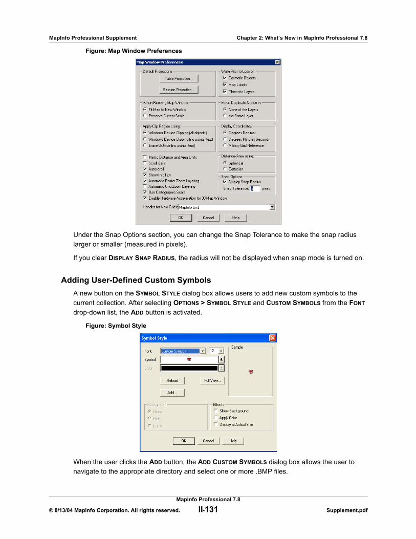
MapInfo Professional Supplement Chapter 2: What’s New in MapInfo Professional 7.8
Figure: Map Window Preferences
Under the Snap Options section, you can change the Snap Tolerance to make the snap radius larger or smaller (measured in pixels).
If you clear DISPLAY SNAP RADIUS, the radius will not be displayed when snap mode is turned on.
Adding User-Defined Custom SymbolsA new button on the SYMBOL STYLE dialog box allows users to add new custom symbols to the current collection. After selecting OPTIONS > SYMBOL STYLE and CUSTOM SYMBOLS from the FONT drop-down list, the ADD button is activated.
Figure: Symbol Style
When the user clicks the ADD button, the ADD CUSTOM SYMBOLS dialog box allows the user to navigate to the appropriate directory and select one or more .BMP files.
MapInfo Professional 7.8
© 8/13/04 MapInfo Corporation. All rights reserved. II-131 Supplement.pdf

MapInfo Professional Supplement Chapter 2: What’s New in MapInfo Professional 7.8
After you click OK, the RESULTS dialog box confirms where the custom symbols were added. The destination CustSymb directory is determined by the during installation. If you executed the MapBasic command to reload custom symbols from a particular directory, then the ADD CUSTOM SYMBOLS dialog box will add to that directory instead. See the Reload Symbols statement in the MapBasic Reference Guide, Version 7.8.
If one or more files cannot be copied, the RESULTS dialog box reports the failure. The copy can fail for a number of reasons, including:
• you may have attempted to overwrite an existing .BMP file of the same name.• the destination file name is too long (greater than MAX_PATH, which is 260 characters for
a 32-bit Windows system).• the destination directory may not exist.• the security permissions on your system prevent copying.
After the symbols have been copied, they are immediately available in the SYMBOL drop-down list.
Figure: Symbol Style with Custom Symbols Selected
New High-Resolution Custom SymbolsMapInfo has added some new high-resolution (24-bit color) custom symbols and updated some existing custom symbols. These are installed along with other custom symbols in the CustSymb directory. The symbols in the Symbol drop-down list are sized to fit into each square cell, so the high resolution images are only approximations of the final image. To change the size of the image, change the font size.
You can see a list of the new high-resolution custom symbols in High-Resolution Custom Symbols in Appendix B on page II-186.
Selecting Sample Size for Cartographic Legend WindowYou can control the sample legend sizes that appear in Cartographic Legend windows. You can choose the smaller sample sizes that were used with MapInfo version 7.0 and earlier, or choose the larger legend sample sizes that were introduced in MapInfo version 7.5. This feature does not affect Thematic Legend windows.
MapInfo Professional 7.8
© 8/13/04 MapInfo Corporation. All rights reserved. II-132 Supplement.pdf
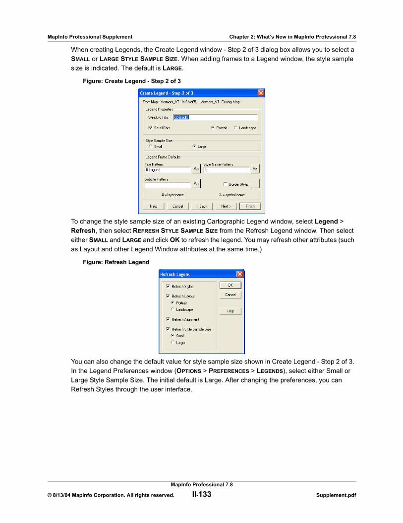
MapInfo Professional Supplement Chapter 2: What’s New in MapInfo Professional 7.8
When creating Legends, the Create Legend window - Step 2 of 3 dialog box allows you to select a SMALL or LARGE STYLE SAMPLE SIZE. When adding frames to a Legend window, the style sample size is indicated. The default is LARGE.
Figure: Create Legend - Step 2 of 3
To change the style sample size of an existing Cartographic Legend window, select Legend > Refresh, then select REFRESH STYLE SAMPLE SIZE from the Refresh Legend window. Then select either SMALL and LARGE and click OK to refresh the legend. You may refresh other attributes (such as Layout and other Legend Window attributes at the same time.)
Figure: Refresh Legend
You can also change the default value for style sample size shown in Create Legend - Step 2 of 3. In the Legend Preferences window (OPTIONS > PREFERENCES > LEGENDS), select either Small or Large Style Sample Size. The initial default is Large. After changing the preferences, you can Refresh Styles through the user interface.
MapInfo Professional 7.8
© 8/13/04 MapInfo Corporation. All rights reserved. II-133 Supplement.pdf
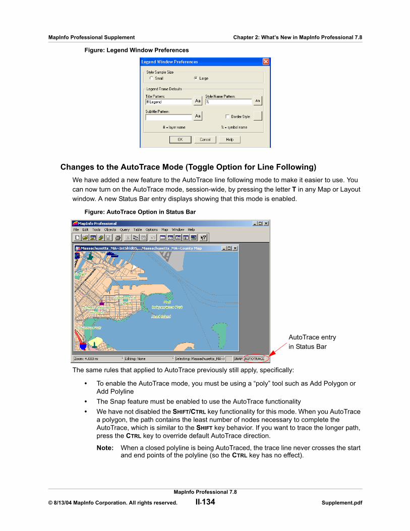
MapInfo Professional Supplement Chapter 2: What’s New in MapInfo Professional 7.8
Figure: Legend Window Preferences
Changes to the AutoTrace Mode (Toggle Option for Line Following)We have added a new feature to the AutoTrace line following mode to make it easier to use. You can now turn on the AutoTrace mode, session-wide, by pressing the letter T in any Map or Layout window. A new Status Bar entry displays showing that this mode is enabled.
Figure: AutoTrace Option in Status Bar
The same rules that applied to AutoTrace previously still apply, specifically:
• To enable the AutoTrace mode, you must be using a “poly” tool such as Add Polygon or Add Polyline
• The Snap feature must be enabled to use the AutoTrace functionality• We have not disabled the SHIFT/CTRL key functionality for this mode. When you AutoTrace
a polygon, the path contains the least number of nodes necessary to complete the AutoTrace, which is similar to the SHIFT key behavior. If you want to trace the longer path, press the CTRL key to override default AutoTrace direction.
Note: When a closed polyline is being AutoTraced, the trace line never crosses the start and end points of the polyline (so the CTRL key has no effect).
AutoTrace entry in Status Bar
MapInfo Professional 7.8
© 8/13/04 MapInfo Corporation. All rights reserved. II-134 Supplement.pdf
MapInfo Professional Supplement Chapter 2: What’s New in MapInfo Professional 7.8
Sample Data Changes AvailableWe have upgraded our sample data, specifically States.tab and USA.tab to include the Census 2000 data. Further, we have added a new ZIPs file (US_ZIPS.tab) to assist you with more accurate geocoding. This file contains the data from our popular ZipInfo product.
3D Enhancements
Improved PrismMap Lighting. We have corrected a problem that affected the way Prism Maps displayed. When you changed the viewpoint of the Prism Map, the colors might look washed out due to an error in the lighting calculation. We have corrected this issue so that PrismMaps have a consistent look regardless of the viewpoint.
Datum Enhancements
This section describes new and updated coordinate systems for MapInfo Professional version 7.8. The MAPINFOW.PRJ file has been updated to support these changes.
French RGF93 Coordinate SystemThe French RGF93 Coordinate System has been added.
When converting coordinates from one datum to another, MapInfo Professional has used the Molodensky (3-parameter) and Bursa-Wolf (7-parameter) methods. These are general-purpose methods that can transform coordinates from any datum to any other datum.
In previous versions of MapInfo Professional, we introduced datum conversion programs to support the specialized NADCON (North American Datum Conversion) and JGD2000 (Japanese Geodetic Datum Conversion) Coordinate Systems. With MapInfo Professional version 7.8. we now support the French Lambert RGF93 Coordinate Systems.
The National Geographic Institute (France) recently introduced a new coordinate system, RGF93, which is based on GRS 80 ellipsoid. In order to convert existing data that uses NTF (New Triangulation of France) datum, the National Geographic Institute provides a transformation "grid". This grid contains parameters that are used to transform NTF coordinates to RGF93 coordinates, and vice versa. MapInfo Professional uses a binary version of this grid file (GR3DF97a.bin) to perform this conversion.
For maximum accuracy of 5 cm or better when converting NTF into RGF93 datum, use a Bounded Lambert RGF93 coordinate system. It is especially necessary to use a bounded Lon\Lat system when converting Lon\Lat (NTF) to or from Lambert RGF93 as MapInfo Professional's accuracy with unbounded Lon\Lat defaults to 10 cm or 4 in.
MapInfo Professional 7.8
© 8/13/04 MapInfo Corporation. All rights reserved. II-135 Supplement.pdf
MapInfo Professional Supplement Chapter 2: What’s New in MapInfo Professional 7.8
The MAPINFOW.PRJ file includes a Bounded French Lambert RGF93 entry for this conversion. For information on creating Bounded Projections, see Accounting for Affine Transformations and Explicit Bounds in Projection Types of the MapInfo Professional 7.8 User Guide (Unabridged) on the Installation CD or use the CoordSysBounds.MBX tool supplied with MapInfo Professional to create bounds in tables.
Note: All transformations are done silently, without any indication of which datum conversion algorithm was used.
Australian Coordinate System ModificationsNew Coordinate Systems
The following Australian State Grids coordinate systems have been added:
• VicGrid66 (AGD66), 3, 12, 7, 145, -37, -36, -38, 2500000, 4500000 (this is a renaming of “VIC Standard Grid”)
• VicGrid94 (GDA94), 3, 116, 7, 145, -37, -36, -38, 2500000, 2500000
The following “Other Australian Projections”, have been added:
• “Australian Lamberts Conformal Conic (AGD66)”, 3, 12, 7, 135, -24, -18, -36, 0, 0• “Australian Lamberts Conformal Conic (AGD84)”, 3, 12, 7, 135, -24, -18, -36, 0, 0• “Australian Lamberts Conformal Conic (GDA94)”, 3, 116, 7, 135, -24, -18, -36, 0, 0• “Australian Antarctic Lambert”, 3, 104,7, 70, -50, -68.5, -74.5, 600000, 600000• “Australian Antarctic Polar Stereographic”, 20, 104,7, 70, -71, 0.972769012892, 600000,
600000
Israeli Coordinate System AddedSeveral Israeli Coordinate Systems have been added.
Swedish Coordinate System AddedSeveral new varieties of the Swedish RT90 Coordinate System have been added.
New Swedish Coordinate Systems (SWEREF 99) AddedSeveral new Swedish Coordinate Systems have been added. These are based on a new standard coordinate system for Sweden named "SWEREF 99".
Reordered/Added Danish Coordinate SystemsThe Danish Coordinate Systems have been re-ordered in the MAPINFOW.PRJ file so that the UTM Zone32 Euref89 coordinate systems appear at the top.
MapInfo Professional 7.8
© 8/13/04 MapInfo Corporation. All rights reserved. II-136 Supplement.pdf
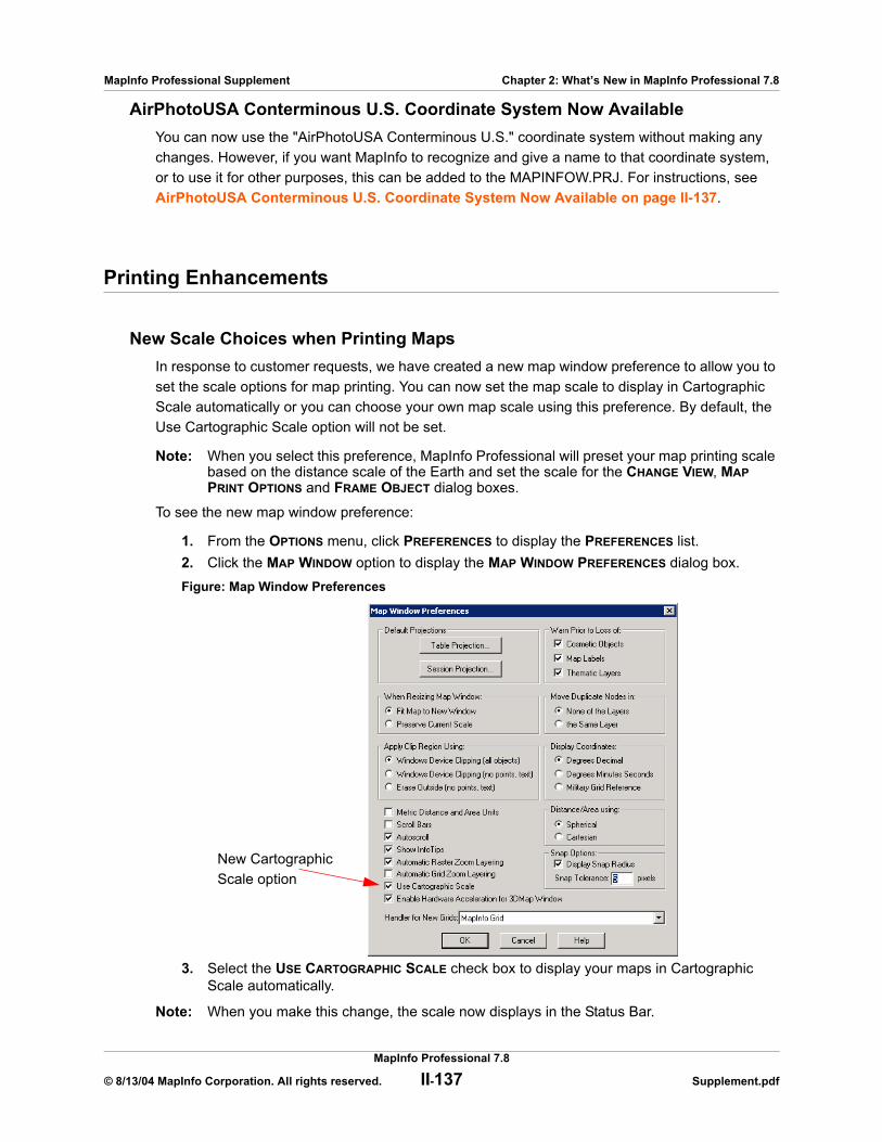
MapInfo Professional Supplement Chapter 2: What’s New in MapInfo Professional 7.8
AirPhotoUSA Conterminous U.S. Coordinate System Now AvailableYou can now use the "AirPhotoUSA Conterminous U.S." coordinate system without making any changes. However, if you want MapInfo to recognize and give a name to that coordinate system, or to use it for other purposes, this can be added to the MAPINFOW.PRJ. For instructions, see AirPhotoUSA Conterminous U.S. Coordinate System Now Available on page II-137.
Printing Enhancements
New Scale Choices when Printing MapsIn response to customer requests, we have created a new map window preference to allow you to set the scale options for map printing. You can now set the map scale to display in Cartographic Scale automatically or you can choose your own map scale using this preference. By default, the Use Cartographic Scale option will not be set.
Note: When you select this preference, MapInfo Professional will preset your map printing scale based on the distance scale of the Earth and set the scale for the CHANGE VIEW, MAP PRINT OPTIONS and FRAME OBJECT dialog boxes.
To see the new map window preference:
1. From the OPTIONS menu, click PREFERENCES to display the PREFERENCES list.2. Click the MAP WINDOW option to display the MAP WINDOW PREFERENCES dialog box.Figure: Map Window Preferences
3. Select the USE CARTOGRAPHIC SCALE check box to display your maps in Cartographic Scale automatically.
Note: When you make this change, the scale now displays in the Status Bar.
New Cartographic Scale option
MapInfo Professional 7.8
© 8/13/04 MapInfo Corporation. All rights reserved. II-137 Supplement.pdf
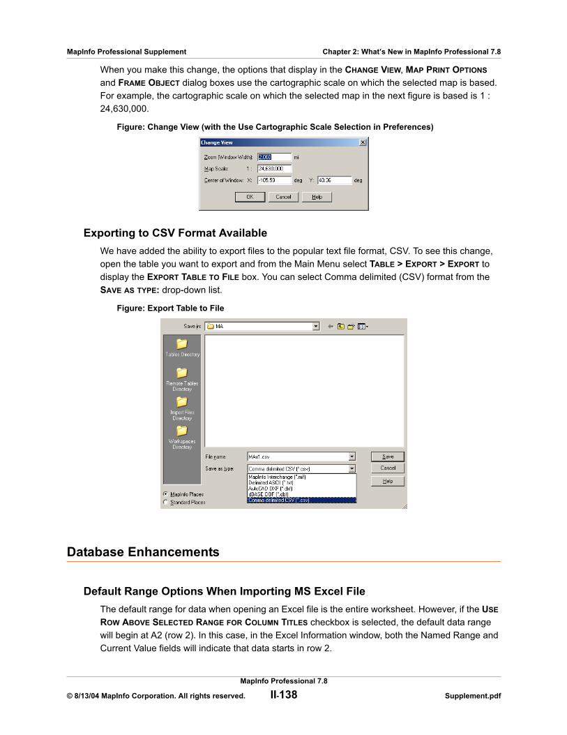
MapInfo Professional Supplement Chapter 2: What’s New in MapInfo Professional 7.8
When you make this change, the options that display in the CHANGE VIEW, MAP PRINT OPTIONS and FRAME OBJECT dialog boxes use the cartographic scale on which the selected map is based. For example, the cartographic scale on which the selected map in the next figure is based is 1 : 24,630,000.
Figure: Change View (with the Use Cartographic Scale Selection in Preferences)
Exporting to CSV Format AvailableWe have added the ability to export files to the popular text file format, CSV. To see this change, open the table you want to export and from the Main Menu select TABLE > EXPORT > EXPORT to display the EXPORT TABLE TO FILE box. You can select Comma delimited (CSV) format from the SAVE AS TYPE: drop-down list.
Figure: Export Table to File
Database Enhancements
Default Range Options When Importing MS Excel FileThe default range for data when opening an Excel file is the entire worksheet. However, if the USE ROW ABOVE SELECTED RANGE FOR COLUMN TITLES checkbox is selected, the default data range will begin at A2 (row 2). In this case, in the Excel Information window, both the Named Range and Current Value fields will indicate that data starts in row 2.
MapInfo Professional 7.8
© 8/13/04 MapInfo Corporation. All rights reserved. II-138 Supplement.pdf
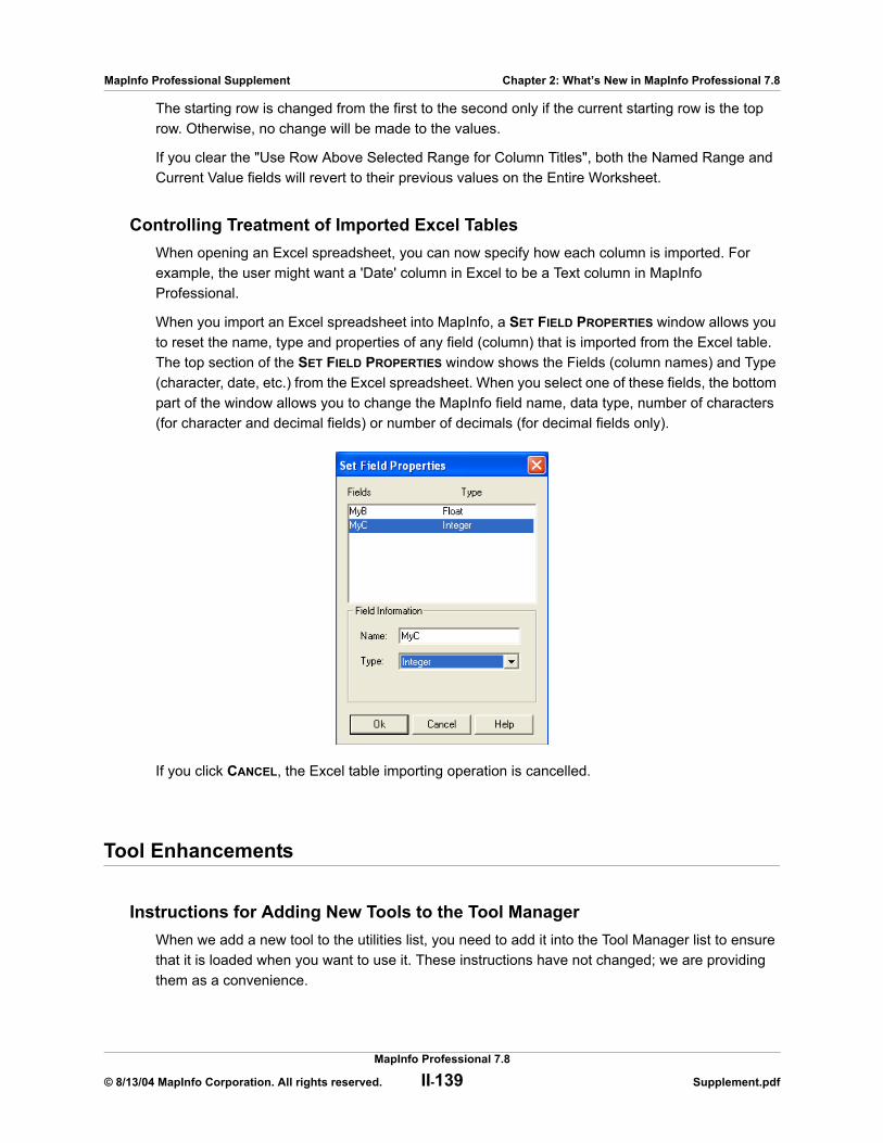
MapInfo Professional Supplement Chapter 2: What’s New in MapInfo Professional 7.8
The starting row is changed from the first to the second only if the current starting row is the top row. Otherwise, no change will be made to the values.
If you clear the "Use Row Above Selected Range for Column Titles", both the Named Range and Current Value fields will revert to their previous values on the Entire Worksheet.
Controlling Treatment of Imported Excel TablesWhen opening an Excel spreadsheet, you can now specify how each column is imported. For example, the user might want a 'Date' column in Excel to be a Text column in MapInfo Professional.
When you import an Excel spreadsheet into MapInfo, a SET FIELD PROPERTIES window allows you to reset the name, type and properties of any field (column) that is imported from the Excel table. The top section of the SET FIELD PROPERTIES window shows the Fields (column names) and Type (character, date, etc.) from the Excel spreadsheet. When you select one of these fields, the bottom part of the window allows you to change the MapInfo field name, data type, number of characters (for character and decimal fields) or number of decimals (for decimal fields only).
If you click CANCEL, the Excel table importing operation is cancelled.
Tool Enhancements
Instructions for Adding New Tools to the Tool ManagerWhen we add a new tool to the utilities list, you need to add it into the Tool Manager list to ensure that it is loaded when you want to use it. These instructions have not changed; we are providing them as a convenience.
MapInfo Professional 7.8
© 8/13/04 MapInfo Corporation. All rights reserved. II-139 Supplement.pdf
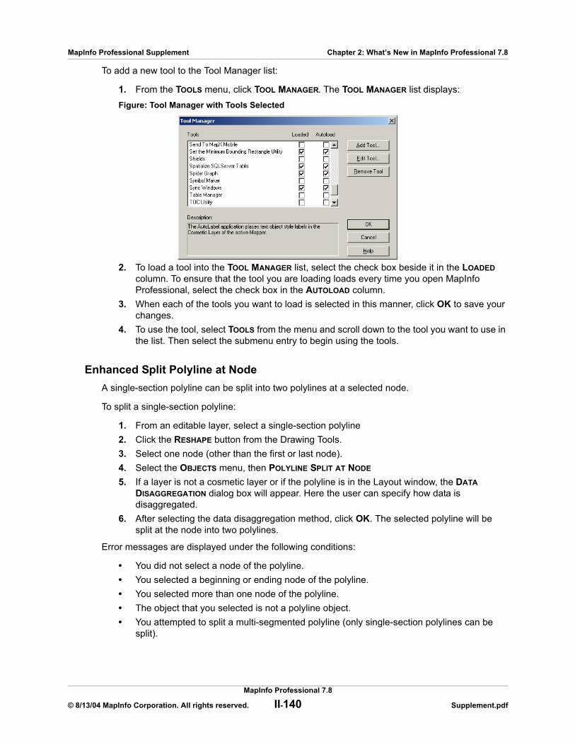
MapInfo Professional Supplement Chapter 2: What’s New in MapInfo Professional 7.8
To add a new tool to the Tool Manager list:
1. From the TOOLS menu, click TOOL MANAGER. The TOOL MANAGER list displays:Figure: Tool Manager with Tools Selected
2. To load a tool into the TOOL MANAGER list, select the check box beside it in the LOADED column. To ensure that the tool you are loading loads every time you open MapInfo Professional, select the check box in the AUTOLOAD column.
3. When each of the tools you want to load is selected in this manner, click OK to save your changes.
4. To use the tool, select TOOLS from the menu and scroll down to the tool you want to use in the list. Then select the submenu entry to begin using the tools.
Enhanced Split Polyline at NodeA single-section polyline can be split into two polylines at a selected node.
To split a single-section polyline:
1. From an editable layer, select a single-section polyline2. Click the RESHAPE button from the Drawing Tools.3. Select one node (other than the first or last node).4. Select the OBJECTS menu, then POLYLINE SPLIT AT NODE 5. If a layer is not a cosmetic layer or if the polyline is in the Layout window, the DATA
DISAGGREGATION dialog box will appear. Here the user can specify how data is disaggregated.
6. After selecting the data disaggregation method, click OK. The selected polyline will be split at the node into two polylines.
Error messages are displayed under the following conditions:
• You did not select a node of the polyline.• You selected a beginning or ending node of the polyline.• You selected more than one node of the polyline.• The object that you selected is not a polyline object.• You attempted to split a multi-segmented polyline (only single-section polylines can be
split).
MapInfo Professional 7.8
© 8/13/04 MapInfo Corporation. All rights reserved. II-140 Supplement.pdf

MapInfo Professional Supplement Chapter 2: What’s New in MapInfo Professional 7.8
Using the Spider Graph ToolThe Spider Graph tool draws lines between objects in a single table, or the objects from two tables based on a join. It then creates a new table of lines that connect the objects from the original table(s) based on matching column names. By default, the lines are color-coded based on their table of origin. Also by default, the new table includes a distance column that stores the length of each line.
To use the Spider Graph tool:
1. Use the Tool Manager to make sure that the Spider Graph tool is loaded.2. With the appropriate MapInfo tables open, select TOOLS > SPIDER GRAPH to activate the
tool.
Note: The Spider Graph tool works with mappable vector tables only. It can not be used with raster images.
3. From the SPIDER GRAPH dialog box, select the origin table from the left drop-down list. Then select the column name that will be used to join the origin table to the destination table.
4. Select the destination table from the right drop-down list. Then select the column name that will be used to join the destination table to the origin table.
5. Select the columns that you want to include in the resulting table. To select multiple columns, hold down the CTRL key while you click. If you do not choose any columns, Spider Graph will automatically include the join column specified for the origin table.
6. By default, the Spider Graph tool will color-code the resulting lines and add a distance column to the new table to record the length of each line. If you do not want these features, clear the appropriate checkbox. The distance lines will use units of miles by default. To change this, select another distance unit from the UNITS: drop-down list.
Figure: Spider Graph
7. Click CREATE LINES and enter a new name for the resulting table in the SAVE COPY AS dialog box.
8. In the SAVE COPY AS window, use the SAVE IN: drop-down list to select the target folder for the resulting .TAB file. In the File name: area, type a file name for the resulting table.
9. Click SAVE.
MapInfo Professional 7.8
© 8/13/04 MapInfo Corporation. All rights reserved. II-141 Supplement.pdf
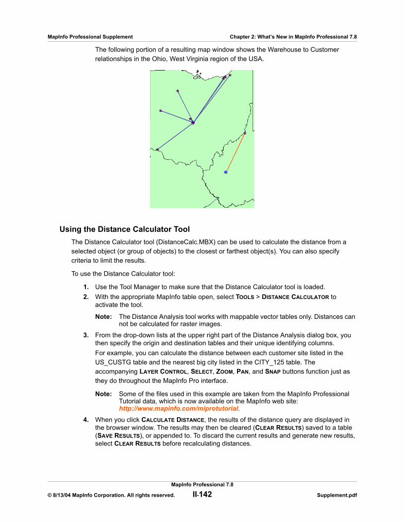
MapInfo Professional Supplement Chapter 2: What’s New in MapInfo Professional 7.8
The following portion of a resulting map window shows the Warehouse to Customer relationships in the Ohio, West Virginia region of the USA.
Using the Distance Calculator ToolThe Distance Calculator tool (DistanceCalc.MBX) can be used to calculate the distance from a selected object (or group of objects) to the closest or farthest object(s). You can also specify criteria to limit the results.
To use the Distance Calculator tool:
1. Use the Tool Manager to make sure that the Distance Calculator tool is loaded.2. With the appropriate MapInfo table open, select TOOLS > DISTANCE CALCULATOR to
activate the tool.
Note: The Distance Analysis tool works with mappable vector tables only. Distances can not be calculated for raster images.
3. From the drop-down lists at the upper right part of the Distance Analysis dialog box, you then specify the origin and destination tables and their unique identifying columns.For example, you can calculate the distance between each customer site listed in the US_CUSTG table and the nearest big city listed in the CITY_125 table. The accompanying LAYER CONTROL, SELECT, ZOOM, PAN, and SNAP buttons function just as they do throughout the MapInfo Pro interface.
Note: Some of the files used in this example are taken from the MapInfo Professional Tutorial data, which is now available on the MapInfo web site:http://www.mapinfo.com/miprotutorial.
4. When you click CALCULATE DISTANCE, the results of the distance query are displayed in the browser window. The results may then be cleared (CLEAR RESULTS) saved to a table (SAVE RESULTS), or appended to. To discard the current results and generate new results, select CLEAR RESULTS before recalculating distances.
MapInfo Professional 7.8
© 8/13/04 MapInfo Corporation. All rights reserved. II-142 Supplement.pdf
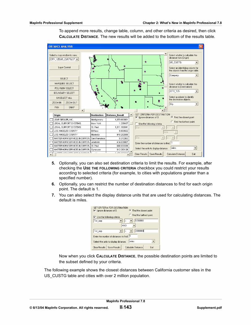
MapInfo Professional Supplement Chapter 2: What’s New in MapInfo Professional 7.8
To append more results, change table, column, and other criteria as desired, then click CALCULATE DISTANCE. The new results will be added to the bottom of the results table.
5. Optionally, you can also set destination criteria to limit the results. For example, after checking the USE THE FOLLOWING CRITERIA checkbox you could restrict your results according to selected criteria (for example, to cities with populations greater than a specified number).
6. Optionally, you can restrict the number of destination distances to find for each origin point. The default is 1.
7. You can also select the display distance units that are used for calculating distances. The default is miles.
Now when you click CALCULATE DISTANCE, the possible destination points are limited to the subset defined by your criteria.
The following example shows the closest distances between California customer sites in the US_CUSTG table and cities with over 2 million population.
MapInfo Professional 7.8
© 8/13/04 MapInfo Corporation. All rights reserved. II-143 Supplement.pdf
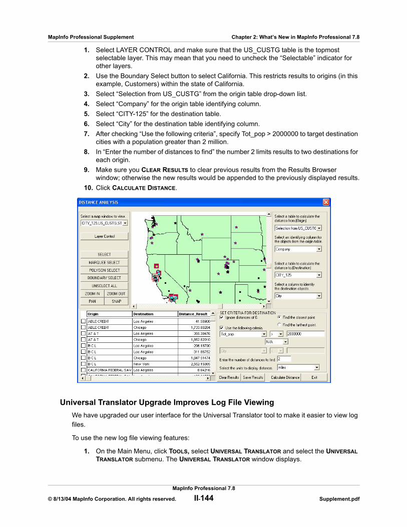
MapInfo Professional Supplement Chapter 2: What’s New in MapInfo Professional 7.8
1. Select LAYER CONTROL and make sure that the US_CUSTG table is the topmost selectable layer. This may mean that you need to uncheck the “Selectable” indicator for other layers.
2. Use the Boundary Select button to select California. This restricts results to origins (in this example, Customers) within the state of California.
3. Select “Selection from US_CUSTG” from the origin table drop-down list.4. Select “Company” for the origin table identifying column.5. Select “CITY-125” for the destination table.6. Select “City” for the destination table identifying column.7. After checking “Use the following criteria”, specify Tot_pop > 2000000 to target destination
cities with a population greater than 2 million.8. In “Enter the number of distances to find” the number 2 limits results to two destinations for
each origin.9. Make sure you CLEAR RESULTS to clear previous results from the Results Browser
window; otherwise the new results would be appended to the previously displayed results.10. Click CALCULATE DISTANCE.
Universal Translator Upgrade Improves Log File ViewingWe have upgraded our user interface for the Universal Translator tool to make it easier to view log files.
To use the new log file viewing features:
1. On the Main Menu, click TOOLS, select UNIVERSAL TRANSLATOR and select the UNIVERSAL TRANSLATOR submenu. The UNIVERSAL TRANSLATOR window displays.
MapInfo Professional 7.8
© 8/13/04 MapInfo Corporation. All rights reserved. II-144 Supplement.pdf
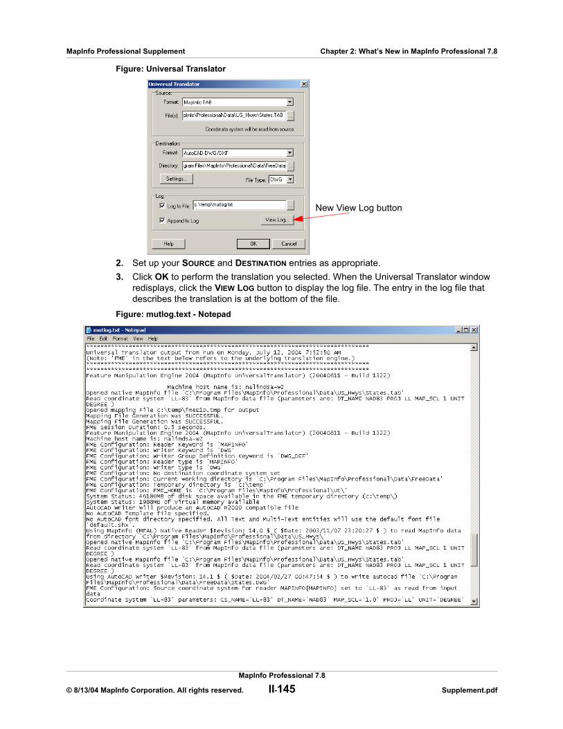
MapInfo Professional Supplement Chapter 2: What’s New in MapInfo Professional 7.8
Figure: Universal Translator
2. Set up your SOURCE and DESTINATION entries as appropriate.3. Click OK to perform the translation you selected. When the Universal Translator window
redisplays, click the VIEW LOG button to display the log file. The entry in the log file that describes the translation is at the bottom of the file.
Figure: mutlog.text - Notepad
New View Log button
MapInfo Professional 7.8
© 8/13/04 MapInfo Corporation. All rights reserved. II-145 Supplement.pdf

MapInfo Professional Supplement Chapter 2: What’s New in MapInfo Professional 7.8
Universal Translator Upgrade Includes Finnish and JDG2000 ProjectionsTo resolve a translation issue, we have added new algorithms for our KKJ datum to the Universal Translator to update the Finnish projection. Additionally the JDG2000 datum has been added to the Universal Translator.
New Tool: The Synchronize Windows UtilityThe Synchronize Windows tool provides toolbar icons that allow you to automatically share changes made in one mapper window to all other mapper windows in a given MapInfo Professional session. For example, you might use this tool to look simultaneously at several sets of complex feature data covering the same location. In cases where a single map containing all the data would be more confusing than helpful, several synchronized maps can often display the information more clearly. The ability to embed thematic legends is useful to provide greater understanding of the data being presented.
The icons on the Sync Windows toolbar are shortcuts to commonly used functionality.
Figure: Sync Windows Toolbar
The Synchronize Windows tool consists of nine icons:
CLONE MAP WINDOW icon
• Provides the same functionality as MAP > CLONE VIEW.
RENAME CURRENT MAP WINDOW icon
• Allows you to rename the currently active Map window.
TILE WINDOWS icon
• Provides the same functionality as WINDOW > TILE WINDOWS.
SYNC ALL MAP WINDOWS icon
• Provides a way to synchronize multiple map windows and embed thematic legends.
CREATE A SYMBOL ON ALL COSMETIC LAYERS icon
• Provides a way to draw a symbol in the same location across multiple map windows.
CREATE A POLYLINE ON ALL COSMETIC LAYERS icon
• Provides a way to draw a polyline in the same location across multiple map windows.
CREATE A RECTANGLE ON ALL COSMETIC LAYERS icon
• Provides a way to draw a rectangle in the same location across multiple map windows.
MapInfo Professional 7.8
© 8/13/04 MapInfo Corporation. All rights reserved. II-146 Supplement.pdf

MapInfo Professional Supplement Chapter 2: What’s New in MapInfo Professional 7.8
CREATE A ELLIPSE ON ALL COSMETIC LAYERS icon
• Provides a way to draw a ellipse in the same location across multiple map windows.
CLEAR COSMETIC LAYERS icon
• Clears the Cosmetic layers of all of all synchronized mapper windows.
Note: This removes all features added to the Cosmetic layers, not just the 'synchronized' features added by this tool during this session.
COGOLine (Create Line by Length) Utility ImprovementsWe have enhanced the COGOLine Utility in response to user requests, particularly in the use of DMS coordinates and the creation of polylines.
In this implementation of the COGOLine tool, the Create Line By Length dialog displays coordinates in the units used by the current map projection (degrees, meters, feet, etc.). For example, if the current map displays degrees as the units, then the COGOLine tool displays the coordinates in decimal degrees, or in DMS coordinates as specified in the Map Options dialog box. Whether the DMS option is selected or not, the new COGOLine tool allows you to enter coordinates in DMS whenever the map has a Long/Lat projection.
Note: On a Longitude/Latitude map, you can type in coordinates using DMS or decimal degrees, even if you did not choose the DEGREES MINUTES SECONDS option in the MAP OPTIONS dialog box.
Customers asked us for the ability to create more complex lines using the COGOLine tool, so we added the capability to create polylines.
Note: If you do not see the CREATE LINE BY LENGTH entry in the TOOLS menu, see the instructions in the beginning of the Tool Enhancements section to add it.
To use the new Create Polyline feature in the PROPERTIES OF NEW LINE dialog box:
1. To run the COGOLine utility, do one of the following:• From the Main Menu, click TOOLS and select the CREATE LINE BY LENGTH entry and
click RUN COGOLINE to display the PROPERTIES OF NEW LINE dialog box.
• Select the CREATE LINE BY LENGTH icon from the TOOLS toolbar, and click the location in the map where you want the new line to begin. The PROPERTIES OF NEW LINE dialog box displays with the coordinate you selected in the STARTING X and STARTING Y fields.
MapInfo Professional 7.8
© 8/13/04 MapInfo Corporation. All rights reserved. II-147 Supplement.pdf
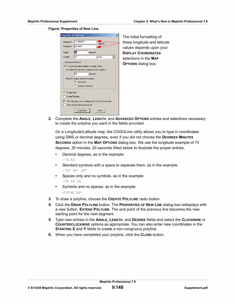
MapInfo Professional Supplement Chapter 2: What’s New in MapInfo Professional 7.8
Figure: Properties of New Line
2. Complete the ANGLE, LENGTH, and ADVANCED OPTIONS entries and selections necessary to create the polyline you want in the fields provided.
On a Longitude/Latitude map, the COGOLine utility allows you to type in coordinates using DMS or decimal degrees, even if you did not choose the DEGREES MINUTES SECONDS option in the MAP OPTIONS dialog box. We use the longitude example of 73 degrees, 30 minutes, 20 seconds West below to illustrate the proper entries.
• Decimal degrees, as in the example:-73.53
• Standard symbols with a space to separate them, as in the example:-73° 30' 20”
• Spaces only and no symbols, as in the example:-73 30 20
• Symbols and no spaces, as in the example: -73°30'20"
3. To draw a polyline, choose the CREATE POLYLINE radio button. 4. Click the DRAW POLYLINE button. The PROPERTIES OF NEW LINE dialog box redisplays with
a new button, EXTEND POLYLINE. The end point of the previous line becomes the new starting point for the next segment.
5. Type new entries in the ANGLE, LENGTH, and DEGREE fields and select the CLOCKWISE or COUNTERCLOCKWISE options as appropriate. You can also enter new coordinates in the STARTING X and Y fields to create a non-congruous polyline.
6. When you have completed your polyline, click the CLOSE button.
The initial formatting of these longitude and latitude values depends upon your DISPLAY COORDINATES selections in the MAP OPTIONS dialog box.
MapInfo Professional 7.8
© 8/13/04 MapInfo Corporation. All rights reserved. II-148 Supplement.pdf
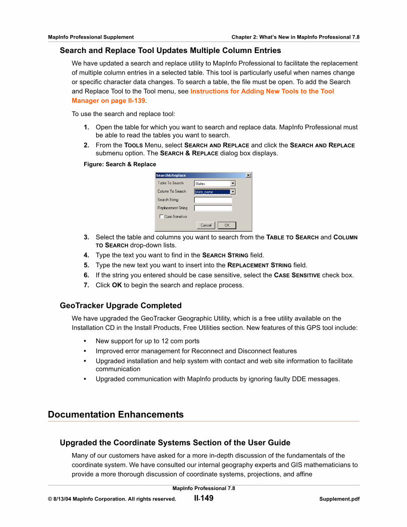
MapInfo Professional Supplement Chapter 2: What’s New in MapInfo Professional 7.8
Search and Replace Tool Updates Multiple Column EntriesWe have updated a search and replace utility to MapInfo Professional to facilitate the replacement of multiple column entries in a selected table. This tool is particularly useful when names change or specific character data changes. To search a table, the file must be open. To add the Search and Replace Tool to the Tool menu, see Instructions for Adding New Tools to the Tool Manager on page II-139.
To use the search and replace tool:
1. Open the table for which you want to search and replace data. MapInfo Professional must be able to read the tables you want to search.
2. From the TOOLS Menu, select SEARCH AND REPLACE and click the SEARCH AND REPLACE submenu option. The SEARCH & REPLACE dialog box displays.
Figure: Search & Replace
3. Select the table and columns you want to search from the TABLE TO SEARCH and COLUMN TO SEARCH drop-down lists.
4. Type the text you want to find in the SEARCH STRING field.5. Type the new text you want to insert into the REPLACEMENT STRING field.6. If the string you entered should be case sensitive, select the CASE SENSITIVE check box.7. Click OK to begin the search and replace process.
GeoTracker Upgrade CompletedWe have upgraded the GeoTracker Geographic Utility, which is a free utility available on the Installation CD in the Install Products, Free Utilities section. New features of this GPS tool include:
• New support for up to 12 com ports• Improved error management for Reconnect and Disconnect features• Upgraded installation and help system with contact and web site information to facilitate
communication• Upgraded communication with Maplnfo products by ignoring faulty DDE messages.
Documentation Enhancements
Upgraded the Coordinate Systems Section of the User GuideMany of our customers have asked for a more in-depth discussion of the fundamentals of the coordinate system. We have consulted our internal geography experts and GIS mathematicians to provide a more thorough discussion of coordinate systems, projections, and affine
MapInfo Professional 7.8
© 8/13/04 MapInfo Corporation. All rights reserved. II-149 Supplement.pdf
MapInfo Professional Supplement Chapter 2: What’s New in MapInfo Professional 7.8
transformations. See Working with Coordinate Systems and Projections in Appendix A on page II-156 for this new resource. This section will also be accessible in the Unabridged User Guide on your installation CD.
Printing Guide 7.8 UpdatedWe have updated the Printing Guide for MapInfo Professional. You can find it in the PDF_DOCS directory on the Installation CD.
Upgraded ProViewer Documentation AvailableWe have upgraded our ProViewer documentation to make it easier to use. You can find it at our web site, http://www.mapinfo.com.
Enhanced Line Style Editor Documentation AvailableIn response to customer requests, we have upgraded our Line Style Editor documentation (MILISTED.PDF) and placed it on the MapInfo web site. It is also in the PDF_DOCS directory on the Installation CD.
MapX Mobile Viewer Documentation To Be AvailableYou can display MapInfo Professional 7.8 .TAB files and geosets on your MapX Mobile Viewer-enabled portable data assistant (PDA). You can also display workspaces if you save them as geosets using the MapX Geoset Utility. Documentation covering this functionality is available on the MapInfo web site.
MapInfo Professional Tutorial and Data AvailableYou can now retrieve the MapInfo Professional Tutorial and associated data from the MapInfo web site at http://www.mapinfo.com or by clicking the MapInfo Tutorial option on the Installation CD. We recommend that you download the tutorial data before you download the tutorial so you can get started right away.
Licensing Enhancements
MapInfo Professional SCP Web License Utility Updated. We have updated the MapInfo Professional SCP to handle MapInfo Professional v7.8 for SCP deployments.
Check for Update in Pro and on Web. When you install MapInfo Professional, you may notice that MapInfo Professional checks the MapInfo web site for any available updates. This ensures that you have the most current software available. This also ensures that users of MapInfo Professional 7.5 are alerted that the 7.8 version is available.
MapInfo Professional 7.8
© 8/13/04 MapInfo Corporation. All rights reserved. II-150 Supplement.pdf
MapInfo Professional Supplement Chapter 2: What’s New in MapInfo Professional 7.8
MapBasic Enhancements
This section describes the MapBasic enhancements that support MapInfo Pro version 7.8.
WFS SupportThe TAB_INFO_TYPE attribute of the TableInfo() function has an additional return of TAB_TYPE_WFS. This indicates that the returned is from a Web Feature Service.
For a description of WFS, see Adding WFS Client Support on page II-113.
The WFS Refresh Table statement refreshes a WFS table from the server. The syntax is:
WFS Refresh Table alias
For a description of WFS, see Refreshing a WFS Layer on page II-120.
The full syntax for the WFS Refresh Table statement is described in the MapBasic Reference Guide, Version 7.8.
MGRS Conversion FunctionsTwo new MapBasic functions allow you to convert a point object to a MGRS (Military Grid Reference System) coordinate, and conversely, to convert an MGRS coordinate to a point object. MGRS is a military grid reference system developed for the USA. It is designed to be used within the WGS84 datum whenever possible.
The MGRSToPoint( ) function converts a string representing an MGRS coordinate to a point object in the current MapBasic coordinate system.
MGRSToPoint (string...)
For example, if the current MapBasic coordinate system is UTM Zone 38 (WGS84), then:
CentroidX(MGRSTOPOINT(“38SlF1781853752”))=317,818.37754071CentroidY(MGRSTOPOINT(“38SlF1781853752”))=4,045,751.9605484
The PointToMGRS$( ) function converts an object value representing a point into a string representing an MGRS coordinate. Only point objects are supported.
PointToMGRS$ (inputobject)
Note: Set the MapBasic CoordSys to Long/Lat (WGS84) to avoid possible loss of precision.
The following example uses the USA_CAPS points table from Sample Data. Copy and paste the following code into a MapBasic window, then select the entire block and press ENTER. This opens the USA_CAPS table and displays a message window with the MGRS location for Albany, NY.
Open Table "USA_CAPS.TAB" InteractiveMap From USA_CAPSSelect * from USA_CAPS where Capital = "Albany"
Set CoordSys Earth Projection 1, 104Print PointToMGRS$(selection.obj)
MapInfo Professional 7.8
© 8/13/04 MapInfo Corporation. All rights reserved. II-151 Supplement.pdf
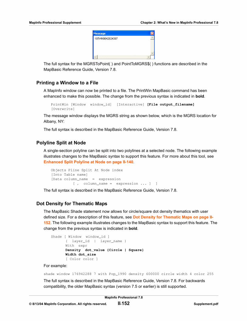
MapInfo Professional Supplement Chapter 2: What’s New in MapInfo Professional 7.8
The full syntax for the MGRSToPoint( ) and PointToMGRS$( ) functions are described in the MapBasic Reference Guide, Version 7.8.
Printing a Window to a FileA MapInfo window can now be printed to a file. The PrintWin MapBasic command has been enhanced to make this possible. The change from the previous syntax is indicated in bold.
PrintWin [Window window_id] [Interactive] [File output_filename][Overwrite]
The message window displays the MGRS string as shown below, which is the MGRS location for Albany, NY:
The full syntax is described in the MapBasic Reference Guide, Version 7.8.
Polyline Split at NodeA single-section polyline can be split into two polylines at a selected node. The following example illustrates changes to the MapBasic syntax to support this feature. For more about this tool, see Enhanced Split Polyline at Node on page II-140.
Objects Pline Split At Node index [Into Table name][Data column_name = expression
[ , column_name = expression ... ] ]
The full syntax is described in the MapBasic Reference Guide, Version 7.8.
Dot Density for Thematic MapsThe MapBasic Shade statement now allows for circle/square dot density thematics with user defined size. For a description of this feature, see Dot Density for Thematic Maps on page II-152. The following example illustrates changes to the MapBasic syntax to support this feature. The change from the previous syntax is indicated in bold.
Shade [ Window window_id ] { layer_id | layer_name } With expr Density dot_value {Circle | Square} Width dot_size[ Color color ]
For example:
shade window 176942288 7 with Pop_1990 density 600000 circle width 4 color 255
The full syntax is described in the MapBasic Reference Guide, Version 7.8. For backwards compatibility, the older MapBasic syntax (version 7.5 or earlier) is still supported.
MapInfo Professional 7.8
© 8/13/04 MapInfo Corporation. All rights reserved. II-152 Supplement.pdf

MapInfo Professional Supplement Chapter 2: What’s New in MapInfo Professional 7.8
Cartographic Legend Sample SizeYou can control the sample legend sizes that appear in Cartographic Legend windows. To support this feature, several MapBasic command have been enhanced. The change from the previous syntax is indicated in bold.
Set Cartographic Legend [ Window legend_window_id ][ Refresh ][ Portrait | Landscape ][ Align][ Style Size {Small | Large}] [ Frame Order { frame_id, frame_id, frame_id, ... } ]
Similarly, the Create Cartographic Legend statement has a new clause that creates the small or large legend sample size.
[ Style Size {Small | Large}
Also the LegendInfo() function has a new LEGEND_INFO_STYLE_SAMPLE_SIZE attribute that returns the legend size information.
For a description of this feature, see Selecting Sample Size for Cartographic Legend Window on page II-132
Excel Column ImportWhen opening an Excel spreadsheet, you can now specify how each column is imported. For a description of this feature, see on Controlling Treatment of Imported Excel Tables on page II-139. The following example illustrates changes to the MapBasic syntax to support this feature. The change from the previous syntax is indicated in bold.
Register Table source_file...
{Type "XLS" [Titles] [Range range_name] [Interactive]...}
The new optional Interactive keyword instructs the interface to display the Set Field Properties window when importing Excel files.
Excel CSV ExportAn Excel table can be exported to a comma-delimited (CSV) file. For a description of this feature, see Exporting to CSV Format Available on page II-138. The following example illustrates changes to the MapBasic syntax to support this feature. The change from the previous Export statement syntax is indicated in bold.
MapInfo Professional 7.8
© 8/13/04 MapInfo Corporation. All rights reserved. II-153 Supplement.pdf

MapInfo Professional Supplement Chapter 2: What’s New in MapInfo Professional 7.8
Syntax 1 (for exporting MIF/MID files, DBF files, ASCII or CSV text files)Export table
Into file_name [ Type
{ “MIF” | “DBF” [ Charset char_set ] | “ASCII” [ Charset char_set ] [ Delimiter “d ” ] [ Titles ] } ]
“CSV” [ Charset char_set ] [ Titles ] } ][ Overwrite ]
Specifying the File FormatThe optional Type clause specifies the format of the file you want to create. The new information is indicated in bold.
When you export a table to an ASCII or CSV text file, the text file will contain delimiters. A delimiter is a special character that separates the fields within each row of data. CSV text files automatically use a comma (“,”) as the delimiter. No other delimiter can be specified for CSV export.
When you export to an ASCII or CSV text file, you may want to include the optional Titles keyword. If you include Titles, the first row of the text file will contain the table's column names. If you omit Titles, the column names will not be stored in the text file (which could be a problem if you intend to re-import the file later).
Running the MapInfo Professional TutorialThe MapInfo Professional tutorial and tutorial sample data can now be accessed directly from the Help menu.
Using MapBasic, the Run Menu Command statement can execute the MapInfo HELP > MAPINFO PROFESSIONAL TUTORIAL ON THE WEB command.
Run Menu Command M_HELP_MAPINFO_WWW_TUTORIAL
Type Clause File Format Specified
Type ”MIF” MapInfo Interchange File format. For information on the MIF file format, see the MapInfo documentation.
Type ”DXF” DXF file (a format supported by CAD packages, such as AutoCAD).
Type ”DBF” dBASE file format. Note: Map objects are not exported when you specify DBF format.
Type ”ASCII” Text file format. Note: Map objects are not exported when you specify ASCII format.
Type "CSV" Comma-delimited text file format. Note: Note: Map objects are not exported when you
specify CSV format.
MapInfo Professional 7.8
© 8/13/04 MapInfo Corporation. All rights reserved. II-154 Supplement.pdf

MapInfo Professional Supplement Chapter 2: What’s New in MapInfo Professional 7.8
MapInfo Professional 7.8
© 8/13/04 MapInfo Corporation. All rights reserved. II-155 Supplement.pdf
A
Working with Coordinate Systems and ProjectionsMaps at their base are a visual representation in two dimensions of a section of the three-dimensional Earth. Being able to use maps in an electronic format in many ways frees us from the constrictions of the two-dimensional map because we can use mathematical formulas to compensate for the curvature of the Earth. In this chapter, we cover the coordinate systems and projections that are standard in MapInfo Professional and provide the tools with which you can create a custom projections to meet your organization’s needs. Whether you are a local government trying to establish new tax rolls or a large company trying to define your sales territory more precisely, creating a custom projection may be a solution you want to explore.
Sections in this Chapter:
Working with Coordinate Systems . . . . . . . . . . . . . . . . . . . . . II-157Building Blocks of a Coordinate System . . . . . . . . . . . . . . . . II-162New Projections in the MAPINFOW.PRJ File . . . . . . . . . . . . . II-178Understanding Affine Transformations . . . . . . . . . . . . . . . . . II-181Frequently Asked Questions. . . . . . . . . . . . . . . . . . . . . . . . . . II-184For More Information . . . . . . . . . . . . . . . . . . . . . . . . . . . . . . . . II-185
MapInfo Professional Supplement Appendix A: Working with Coordinate Systems and Projections
Working with Coordinate Systems
The terms “projection” and “coordinate system” are often used interchangeably, however they do not mean the same thing.
Projection - An equation or set of equations that contain mathematical parameters for a map. The exact number and nature of the parameters depends upon the type of projection. A projection is a method of reducing a map’s distortion caused by the curvature of the Earth, or more precisely, a projection compensates for the shortcomings of depicting maps in two dimensions when the coordinates exist in three dimensions.
Coordinate System - When parameters of a projection are assigned specific values, they become a coordinate system. A coordinate system is a collection of parameters that describe coordinates, one of which is a projection.
Elements of a Coordinate SystemA coordinate system in MapInfo Professional is made up of many elements which need to be specified in advance. Once these elements are in place, you can be sure that your maps are as accurate as possible. These are the projection elements you need to set in the MAPINFOW.PRJ file:
• Projection Types • Datums• Units• Coordinate System Origin• Standard Parallels (Conic Projections)• Oblique Azimuth (Hotine Oblique Mercator)• Scale Factor (Transverse Mercator)• False Easting and False Northing• Range (Azimuthal Projections)
Understanding Coordinate SystemsYou can make a map out of any globe without distorting the points on the surface by placing the globe into an imaginary cylinder.
MapInfo Professional 7.8
© 8/13/04 MapInfo Corporation. All rights reserved. II-157 Supplement.pdf
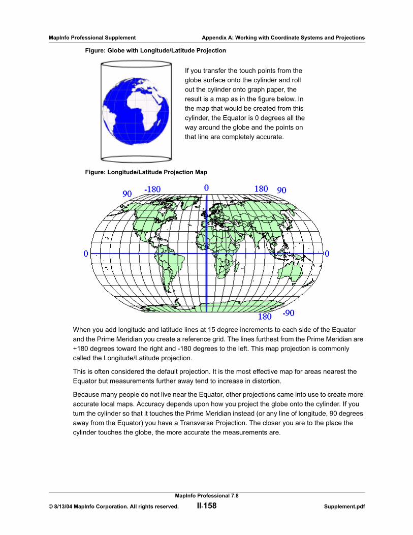
MapInfo Professional Supplement Appendix A: Working with Coordinate Systems and Projections
Figure: Globe with Longitude/Latitude Projection
Figure: Longitude/Latitude Projection Map
When you add longitude and latitude lines at 15 degree increments to each side of the Equator and the Prime Meridian you create a reference grid. The lines furthest from the Prime Meridian are +180 degrees toward the right and -180 degrees to the left. This map projection is commonly called the Longitude/Latitude projection.
This is often considered the default projection. It is the most effective map for areas nearest the Equator but measurements further away tend to increase in distortion.
Because many people do not live near the Equator, other projections came into use to create more accurate local maps. Accuracy depends upon how you project the globe onto the cylinder. If you turn the cylinder so that it touches the Prime Meridian instead (or any line of longitude, 90 degrees away from the Equator) you have a Transverse Projection. The closer you are to the place the cylinder touches the globe, the more accurate the measurements are.
If you transfer the touch points from the globe surface onto the cylinder and roll out the cylinder onto graph paper, the result is a map as in the figure below. In the map that would be created from this cylinder, the Equator is 0 degrees all the way around the globe and the points on that line are completely accurate.
MapInfo Professional 7.8
© 8/13/04 MapInfo Corporation. All rights reserved. II-158 Supplement.pdf
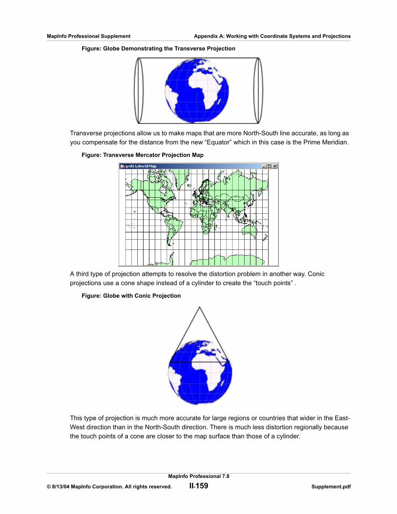
MapInfo Professional Supplement Appendix A: Working with Coordinate Systems and Projections
Figure: Globe Demonstrating the Transverse Projection
Transverse projections allow us to make maps that are more North-South line accurate, as long as you compensate for the distance from the new “Equator” which in this case is the Prime Meridian.
Figure: Transverse Mercator Projection Map
A third type of projection attempts to resolve the distortion problem in another way. Conic projections use a cone shape instead of a cylinder to create the “touch points” .
Figure: Globe with Conic Projection
This type of projection is much more accurate for large regions or countries that wider in the East-West direction than in the North-South direction. There is much less distortion regionally because the touch points of a cone are closer to the map surface than those of a cylinder.
MapInfo Professional 7.8
© 8/13/04 MapInfo Corporation. All rights reserved. II-159 Supplement.pdf
MapInfo Professional Supplement Appendix A: Working with Coordinate Systems and Projections
Figure: Brazilian Polyconic Projection Map
As you can see from the previous figure, the conic maps are best for small regional areas. The larger-scale map has too much distortion to be useful.
A fourth type of projection, the Azimuthal projection, does not use cones or cylinders but a simple circle that goes all the way around the globe over a particular point. This projection provides a “view from space” over a particular point.
Figure: Globe with Azimuthal Projection
This type of projection is most useful when you need to work with a particular hemisphere. A hemisphere need not be North-South or East-West based. The next figure uses the North Pole as the center point for the Azimuthal Projection.
MapInfo Professional 7.8
© 8/13/04 MapInfo Corporation. All rights reserved. II-160 Supplement.pdf

MapInfo Professional Supplement Appendix A: Working with Coordinate Systems and Projections
Figure: Lambert Azimuthal Projection Map
You can use more than one projection that rotates a cylinder slightly along the Equator. This style is used in the Universal Transverse Mercator (UTM) projection. UTM maps the Earth with a transverse cylinder projection to create standard "UTM Zones". By rotating the cylinder around the globe in six degree increments, the UTM assures that all spots on the Earth are within 3 degrees of the center line. (The Gauss-Kruger system is a European system akin to UTM that also uses a transverse cylinder rotated in six degree steps).
Figure: Universal Transverse Mercator Projection Map (UTM Zone 29)
This expanded view illustrates what happens when UTM is used for maps that are much larger than a six degree zone.
Almost all projections you will use are one of these types. They are either cylindrical (regular or transverse), conic, or azimuthal projections and are customized by slightly different projection parameters. Projection parameters are options that describe how the projection is arranged.
You can further customize projections by specifying different parameters for the projection you want to use. For example, you can specify the longitude and latitude of any point on the Earth to create your own Azimuthal projection of that point. You can customize conic projections by specifying the parallel of latitude at which the cone should be tangent.
MapInfo Professional 7.8
© 8/13/04 MapInfo Corporation. All rights reserved. II-161 Supplement.pdf
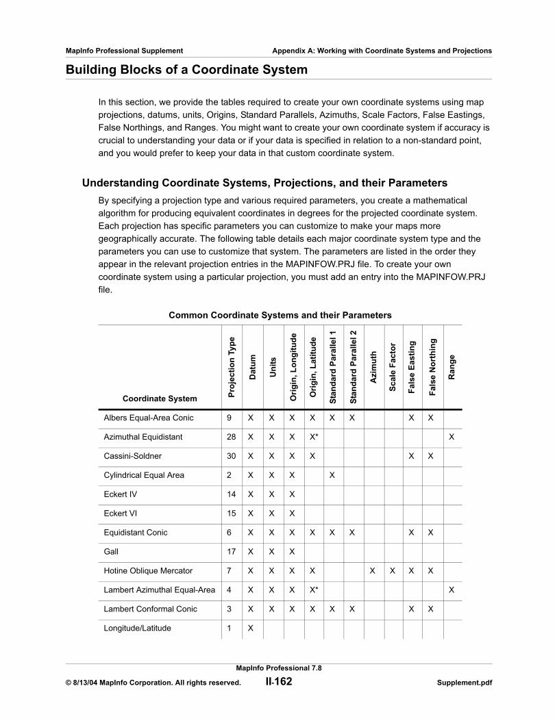
MapInfo Professional Supplement Appendix A: Working with Coordinate Systems and Projections
Building Blocks of a Coordinate System
In this section, we provide the tables required to create your own coordinate systems using map projections, datums, units, Origins, Standard Parallels, Azimuths, Scale Factors, False Eastings, False Northings, and Ranges. You might want to create your own coordinate system if accuracy is crucial to understanding your data or if your data is specified in relation to a non-standard point, and you would prefer to keep your data in that custom coordinate system.
Understanding Coordinate Systems, Projections, and their ParametersBy specifying a projection type and various required parameters, you create a mathematical algorithm for producing equivalent coordinates in degrees for the projected coordinate system. Each projection has specific parameters you can customize to make your maps more geographically accurate. The following table details each major coordinate system type and the parameters you can use to customize that system. The parameters are listed in the order they appear in the relevant projection entries in the MAPINFOW.PRJ file. To create your own coordinate system using a particular projection, you must add an entry into the MAPINFOW.PRJ file.
Common Coordinate Systems and their Parameters
Coordinate System Proj
ectio
n Ty
pe
Dat
um
Uni
ts
Orig
in, L
ongi
tude
Orig
in, L
atitu
de
Stan
dard
Par
alle
l 1
Stan
dard
Par
alle
l 2
Azi
mut
h
Scal
e Fa
ctor
Fals
e Ea
stin
g
Fals
e N
orth
ing
Ran
ge
Albers Equal-Area Conic 9 X X X X X X X X
Azimuthal Equidistant 28 X X X X* X
Cassini-Soldner 30 X X X X X X
Cylindrical Equal Area 2 X X X X
Eckert IV 14 X X X
Eckert VI 15 X X X
Equidistant Conic 6 X X X X X X X X
Gall 17 X X X
Hotine Oblique Mercator 7 X X X X X X X X
Lambert Azimuthal Equal-Area 4 X X X X* X
Lambert Conformal Conic 3 X X X X X X X X
Longitude/Latitude 1 X
MapInfo Professional 7.8
© 8/13/04 MapInfo Corporation. All rights reserved. II-162 Supplement.pdf

MapInfo Professional Supplement Appendix A: Working with Coordinate Systems and Projections
* In MapInfo Professional 6.0, we introduced an Oblique Azimuthal Equidistant projection that supports all Origin Latitudes, including the poles. In MapInfo Professional 6.5, we added a new Lambert Azimuthal Equal-Area projection that also supports all Origin Latitudes, including the poles.
Note: Each of these headings is described in detail in the next few pages.
Projection TypesThe following list names the projection types used in the MAPINFOW.PRJ file.
Mercator 10 X X X
Miller 11 X X X
Mollweide 13 X X X
New Zealand Map Grid 18 X X X X X X
Polyconic 27 X X X X X X
P.E.I. Double Stereographic 31 X X X X X X
Regional Mercator 26 X X X X
Robinson 12 X X X
Sinusoidal 16 X X X
Stereographic 20 X X X X X X X
Swiss Oblique Mercator 25 X X X X X X
Transverse Mercator 8 X X X X X X X
MapInfo Professional Projection Types Table
Number Projection
9 Albers Equal-Area Conic
28 Azimuthal Equidistant (all origin latitudes)
5 Azimuthal Equidistant (polar aspect only)
30 Cassini-Soldner
2 Cylindrical Equal-Area
Common Coordinate Systems and their Parameters (continued)
Coordinate System Proj
ectio
n Ty
pe
Dat
um
Uni
ts
Orig
in, L
ongi
tude
Orig
in, L
atitu
de
Stan
dard
Par
alle
l 1
Stan
dard
Par
alle
l 2
Azi
mut
h
Scal
e Fa
ctor
Fals
e Ea
stin
g
Fals
e N
orth
ing
Ran
ge
MapInfo Professional 7.8
© 8/13/04 MapInfo Corporation. All rights reserved. II-163 Supplement.pdf

MapInfo Professional Supplement Appendix A: Working with Coordinate Systems and Projections
Accounting for Affine Transformations and Explicit Bounds in Projection TypesYou can modify projection type entries in the MAPINFOW.PRJ to add a constant value to account for affine transformations and explicit bounds. Valid values and their meanings are listed below:
14 Eckert IV
15 Eckert VI
6 Equidistant Conic, also known as Simple Conic
17 Gall
7 Hotine Oblique Mercator
4 Lambert Azimuthal Equal-Area (polar aspect only)
29 Lambert Azimuthal Equal-Area
3 Lambert Conformal Conic
19 Lambert Conformal Conic (modified for Belgium 1972)
1 Longitude/Latitude
10 Mercator
11 Miller Cylindrical
13 Mollweide
18 New Zealand Map Grid
31 Prince Edward Island Double Stereographic
27 Polyconic
26 Regional Mercator
12 Robinson
16 Sinusoidal
20 Stereographic
25 Swiss Oblique Mercator
8 Transverse Mercator (also known as Gauss-Kruger)
21 Transverse Mercator (modified for Danish System 34 Jylland-Fyn)
22 Transverse Mercator (modified for Danish System 34 Sjaelland)
23 Transverse Mercator (modified for Danish System 34/45 Bornholm)
24 Transverse Mercator (modified for Finnish KKJ)
MapInfo Professional Projection Types Table (continued)
Number Projection
MapInfo Professional 7.8
© 8/13/04 MapInfo Corporation. All rights reserved. II-164 Supplement.pdf
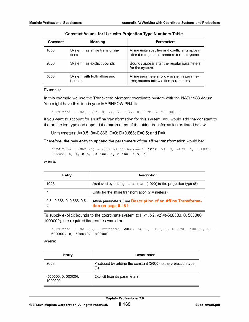
MapInfo Professional Supplement Appendix A: Working with Coordinate Systems and Projections
Example:
In this example we use the Transverse Mercator coordinate system with the NAD 1983 datum. You might have this line in your MAPINFOW.PRJ file:
"UTM Zone 1 (NAD 83)", 8, 74, 7, -177, 0, 0.9996, 500000, 0
If you want to account for an affine transformation for this system, you would add the constant to the projection type and append the parameters of the affine transformation as listed below:
Units=meters; A=0.5; B=-0.866; C=0; D=0.866; E=0.5; and F=0
Therefore, the new entry to append the parameters of the affine transformation would be:
"UTM Zone 1 (NAD 83) - rotated 60 degrees", 1008, 74, 7, -177, 0, 0.9996,
500000, 0, 7, 0.5, -0.866, 0, 0.866, 0.5, 0
where:
To supply explicit bounds to the coordinate system (x1, y1, x2, y2)=(-500000, 0, 500000, 1000000), the required line entries would be:
"UTM Zone 1 (NAD 83) - bounded", 2008, 74, 7, -177, 0, 0.9996, 500000, 0, -
500000, 0, 500000, 1000000
where:
Constant Values for Use with Projection Type Numbers Table
Constant Meaning Parameters
1000 System has affine transforma-tions
Affine units specifier and coefficients appear after the regular parameters for the system.
2000 System has explicit bounds Bounds appear after the regular parameters for the system.
3000 System with both affine and bounds
Affine parameters follow system’s parame-ters; bounds follow affine parameters.
Entry Description
1008 Achieved by adding the constant (1000) to the projection type (8)
7 Units for the affine transformation (7 = meters)
0.5, -0.866, 0, 0.866, 0.5, 0
Affine parameters (See Description of an Affine Transforma-tion on page II-181.)
Entry Description
2008 Produced by adding the constant (2000) to the projection type (8)
-500000, 0, 500000, 1000000
Explicit bounds parameters
MapInfo Professional 7.8
© 8/13/04 MapInfo Corporation. All rights reserved. II-165 Supplement.pdf
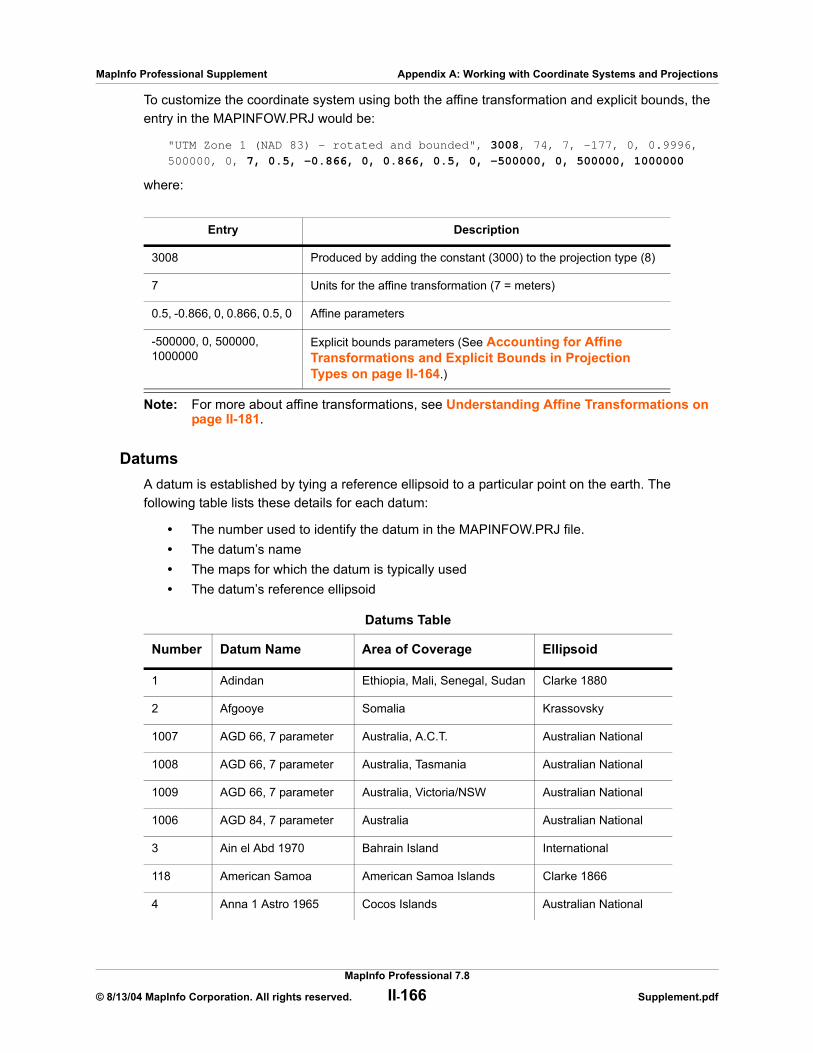
MapInfo Professional Supplement Appendix A: Working with Coordinate Systems and Projections
To customize the coordinate system using both the affine transformation and explicit bounds, the entry in the MAPINFOW.PRJ would be:
"UTM Zone 1 (NAD 83) - rotated and bounded", 3008, 74, 7, -177, 0, 0.9996,
500000, 0, 7, 0.5, -0.866, 0, 0.866, 0.5, 0, -500000, 0, 500000, 1000000
where:
Note: For more about affine transformations, see Understanding Affine Transformations on page II-181.
DatumsA datum is established by tying a reference ellipsoid to a particular point on the earth. The following table lists these details for each datum:
• The number used to identify the datum in the MAPINFOW.PRJ file.• The datum’s name• The maps for which the datum is typically used• The datum’s reference ellipsoid
Entry Description
3008 Produced by adding the constant (3000) to the projection type (8)
7 Units for the affine transformation (7 = meters)
0.5, -0.866, 0, 0.866, 0.5, 0 Affine parameters
-500000, 0, 500000, 1000000
Explicit bounds parameters (See Accounting for Affine Transformations and Explicit Bounds in Projection Types on page II-164.)
Datums Table
Number Datum Name Area of Coverage Ellipsoid
1 Adindan Ethiopia, Mali, Senegal, Sudan Clarke 1880
2 Afgooye Somalia Krassovsky
1007 AGD 66, 7 parameter Australia, A.C.T. Australian National
1008 AGD 66, 7 parameter Australia, Tasmania Australian National
1009 AGD 66, 7 parameter Australia, Victoria/NSW Australian National
1006 AGD 84, 7 parameter Australia Australian National
3 Ain el Abd 1970 Bahrain Island International
118 American Samoa American Samoa Islands Clarke 1866
4 Anna 1 Astro 1965 Cocos Islands Australian National
MapInfo Professional 7.8
© 8/13/04 MapInfo Corporation. All rights reserved. II-166 Supplement.pdf
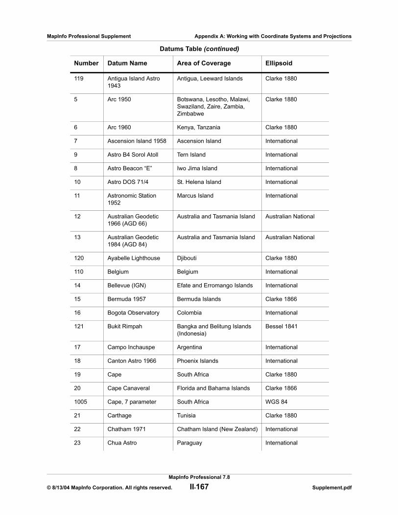
MapInfo Professional Supplement Appendix A: Working with Coordinate Systems and Projections
119 Antigua Island Astro 1943
Antigua, Leeward Islands Clarke 1880
5 Arc 1950 Botswana, Lesotho, Malawi, Swaziland, Zaire, Zambia, Zimbabwe
Clarke 1880
6 Arc 1960 Kenya, Tanzania Clarke 1880
7 Ascension Island 1958 Ascension Island International
9 Astro B4 Sorol Atoll Tern Island International
8 Astro Beacon “E” Iwo Jima Island International
10 Astro DOS 71/4 St. Helena Island International
11 Astronomic Station 1952
Marcus Island International
12 Australian Geodetic 1966 (AGD 66)
Australia and Tasmania Island Australian National
13 Australian Geodetic 1984 (AGD 84)
Australia and Tasmania Island Australian National
120 Ayabelle Lighthouse Djibouti Clarke 1880
110 Belgium Belgium International
14 Bellevue (IGN) Efate and Erromango Islands International
15 Bermuda 1957 Bermuda Islands Clarke 1866
16 Bogota Observatory Colombia International
121 Bukit Rimpah Bangka and Belitung Islands (Indonesia)
Bessel 1841
17 Campo Inchauspe Argentina International
18 Canton Astro 1966 Phoenix Islands International
19 Cape South Africa Clarke 1880
20 Cape Canaveral Florida and Bahama Islands Clarke 1866
1005 Cape, 7 parameter South Africa WGS 84
21 Carthage Tunisia Clarke 1880
22 Chatham 1971 Chatham Island (New Zealand) International
23 Chua Astro Paraguay International
Datums Table (continued)
Number Datum Name Area of Coverage Ellipsoid
MapInfo Professional 7.8
© 8/13/04 MapInfo Corporation. All rights reserved. II-167 Supplement.pdf
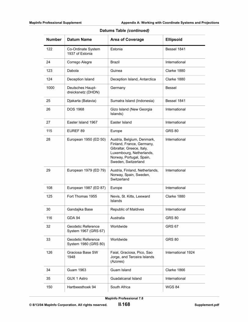
MapInfo Professional Supplement Appendix A: Working with Coordinate Systems and Projections
122 Co-Ordinate System 1937 of Estonia
Estonia Bessel 1841
24 Corrego Alegre Brazil International
123 Dabola Guinea Clarke 1880
124 Deception Island Deception Island, Antarctica Clarke 1880
1000 Deutsches Haupt-dreicksnetz (DHDN)
Germany Bessel
25 Djakarta (Batavia) Sumatra Island (Indonesia) Bessel 1841
26 DOS 1968 Gizo Island (New Georgia Islands)
International
27 Easter Island 1967 Easter Island International
115 EUREF 89 Europe GRS 80
28 European 1950 (ED 50) Austria, Belgium, Denmark, Finland, France, Germany, Gibraltar, Greece, Italy, Luxembourg, Netherlands, Norway, Portugal, Spain, Sweden, Switzerland
International
29 European 1979 (ED 79) Austria, Finland, Netherlands, Norway, Spain, Sweden, Switzerland
International
108 European 1987 (ED 87) Europe International
125 Fort Thomas 1955 Nevis, St. Kitts, Leeward Islands
Clarke 1880
30 Gandajika Base Republic of Maldives International
116 GDA 94 Australia GRS 80
32 Geodetic Reference System 1967 (GRS 67)
Worldwide GRS 67
33 Geodetic Reference System 1980 (GRS 80)
Worldwide GRS 80
126 Graciosa Base SW 1948
Faial, Graciosa, Pico, Sao Jorge, and Terceira Islands (Azores)
International 1924
34 Guam 1963 Guam Island Clarke 1866
35 GUX 1 Astro Guadalcanal Island International
150 Hartbeesthoek 94 South Africa WGS 84
Datums Table (continued)
Number Datum Name Area of Coverage Ellipsoid
MapInfo Professional 7.8
© 8/13/04 MapInfo Corporation. All rights reserved. II-168 Supplement.pdf
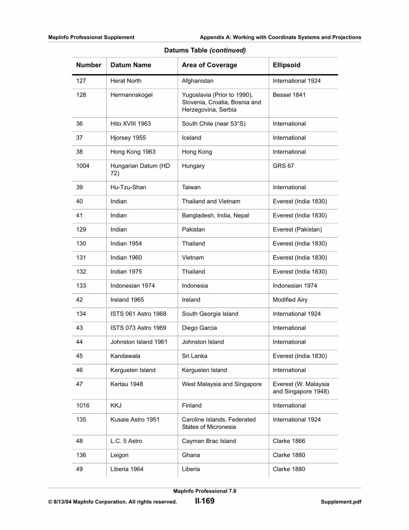
MapInfo Professional Supplement Appendix A: Working with Coordinate Systems and Projections
127 Herat North Afghanistan International 1924
128 Hermannskogel Yugoslavia (Prior to 1990), Slovenia, Croatia, Bosnia and Herzegovina, Serbia
Bessel 1841
36 Hito XVIII 1963 South Chile (near 53°S) International
37 Hjorsey 1955 Iceland International
38 Hong Kong 1963 Hong Kong International
1004 Hungarian Datum (HD 72)
Hungary GRS 67
39 Hu-Tzu-Shan Taiwan International
40 Indian Thailand and Vietnam Everest (India 1830)
41 Indian Bangladesh, India, Nepal Everest (India 1830)
129 Indian Pakistan Everest (Pakistan)
130 Indian 1954 Thailand Everest (India 1830)
131 Indian 1960 Vietnam Everest (India 1830)
132 Indian 1975 Thailand Everest (India 1830)
133 Indonesian 1974 Indonesia Indonesian 1974
42 Ireland 1965 Ireland Modified Airy
134 ISTS 061 Astro 1968 South Georgia Island International 1924
43 ISTS 073 Astro 1969 Diego Garcia International
44 Johnston Island 1961 Johnston Island International
45 Kandawala Sri Lanka Everest (India 1830)
46 Kerguelen Island Kerguelen Island International
47 Kertau 1948 West Malaysia and Singapore Everest (W. Malaysia and Singapore 1948)
1016 KKJ Finland International
135 Kusaie Astro 1951 Caroline Islands, Federated States of Micronesia
International 1924
48 L.C. 5 Astro Cayman Brac Island Clarke 1866
136 Leigon Ghana Clarke 1880
49 Liberia 1964 Liberia Clarke 1880
Datums Table (continued)
Number Datum Name Area of Coverage Ellipsoid
MapInfo Professional 7.8
© 8/13/04 MapInfo Corporation. All rights reserved. II-169 Supplement.pdf
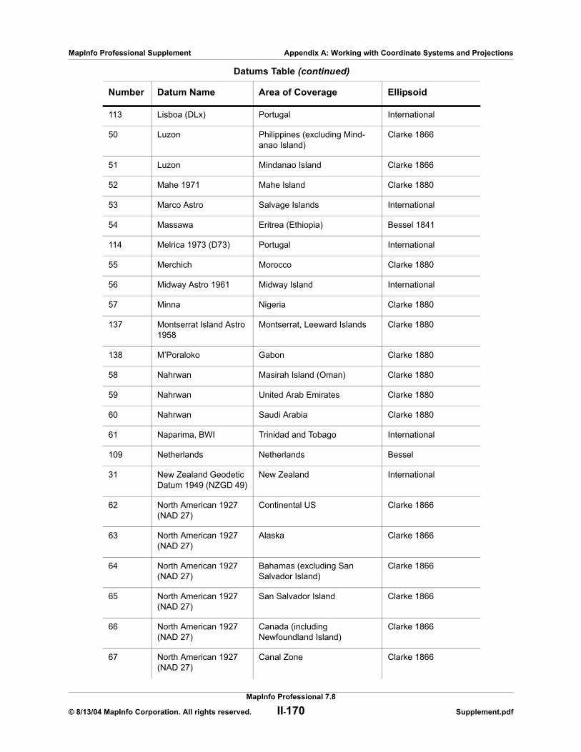
MapInfo Professional Supplement Appendix A: Working with Coordinate Systems and Projections
113 Lisboa (DLx) Portugal International
50 Luzon Philippines (excluding Mind-anao Island)
Clarke 1866
51 Luzon Mindanao Island Clarke 1866
52 Mahe 1971 Mahe Island Clarke 1880
53 Marco Astro Salvage Islands International
54 Massawa Eritrea (Ethiopia) Bessel 1841
114 Melrica 1973 (D73) Portugal International
55 Merchich Morocco Clarke 1880
56 Midway Astro 1961 Midway Island International
57 Minna Nigeria Clarke 1880
137 Montserrat Island Astro 1958
Montserrat, Leeward Islands Clarke 1880
138 M’Poraloko Gabon Clarke 1880
58 Nahrwan Masirah Island (Oman) Clarke 1880
59 Nahrwan United Arab Emirates Clarke 1880
60 Nahrwan Saudi Arabia Clarke 1880
61 Naparima, BWI Trinidad and Tobago International
109 Netherlands Netherlands Bessel
31 New Zealand Geodetic Datum 1949 (NZGD 49)
New Zealand International
62 North American 1927(NAD 27)
Continental US Clarke 1866
63 North American 1927(NAD 27)
Alaska Clarke 1866
64 North American 1927(NAD 27)
Bahamas (excluding San Salvador Island)
Clarke 1866
65 North American 1927(NAD 27)
San Salvador Island Clarke 1866
66 North American 1927(NAD 27)
Canada (including Newfoundland Island)
Clarke 1866
67 North American 1927(NAD 27)
Canal Zone Clarke 1866
Datums Table (continued)
Number Datum Name Area of Coverage Ellipsoid
MapInfo Professional 7.8
© 8/13/04 MapInfo Corporation. All rights reserved. II-170 Supplement.pdf
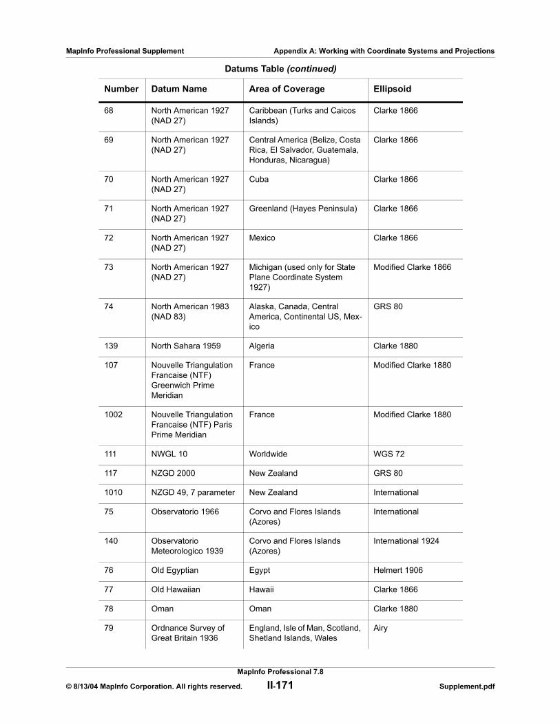
MapInfo Professional Supplement Appendix A: Working with Coordinate Systems and Projections
68 North American 1927(NAD 27)
Caribbean (Turks and Caicos Islands)
Clarke 1866
69 North American 1927(NAD 27)
Central America (Belize, Costa Rica, El Salvador, Guatemala, Honduras, Nicaragua)
Clarke 1866
70 North American 1927(NAD 27)
Cuba Clarke 1866
71 North American 1927(NAD 27)
Greenland (Hayes Peninsula) Clarke 1866
72 North American 1927(NAD 27)
Mexico Clarke 1866
73 North American 1927(NAD 27)
Michigan (used only for State Plane Coordinate System 1927)
Modified Clarke 1866
74 North American 1983(NAD 83)
Alaska, Canada, Central America, Continental US, Mex-ico
GRS 80
139 North Sahara 1959 Algeria Clarke 1880
107 Nouvelle Triangulation Francaise (NTF) Greenwich Prime Meridian
France Modified Clarke 1880
1002 Nouvelle Triangulation Francaise (NTF) Paris Prime Meridian
France Modified Clarke 1880
111 NWGL 10 Worldwide WGS 72
117 NZGD 2000 New Zealand GRS 80
1010 NZGD 49, 7 parameter New Zealand International
75 Observatorio 1966 Corvo and Flores Islands (Azores)
International
140 Observatorio Meteorologico 1939
Corvo and Flores Islands (Azores)
International 1924
76 Old Egyptian Egypt Helmert 1906
77 Old Hawaiian Hawaii Clarke 1866
78 Oman Oman Clarke 1880
79 Ordnance Survey of Great Britain 1936
England, Isle of Man, Scotland, Shetland Islands, Wales
Airy
Datums Table (continued)
Number Datum Name Area of Coverage Ellipsoid
MapInfo Professional 7.8
© 8/13/04 MapInfo Corporation. All rights reserved. II-171 Supplement.pdf
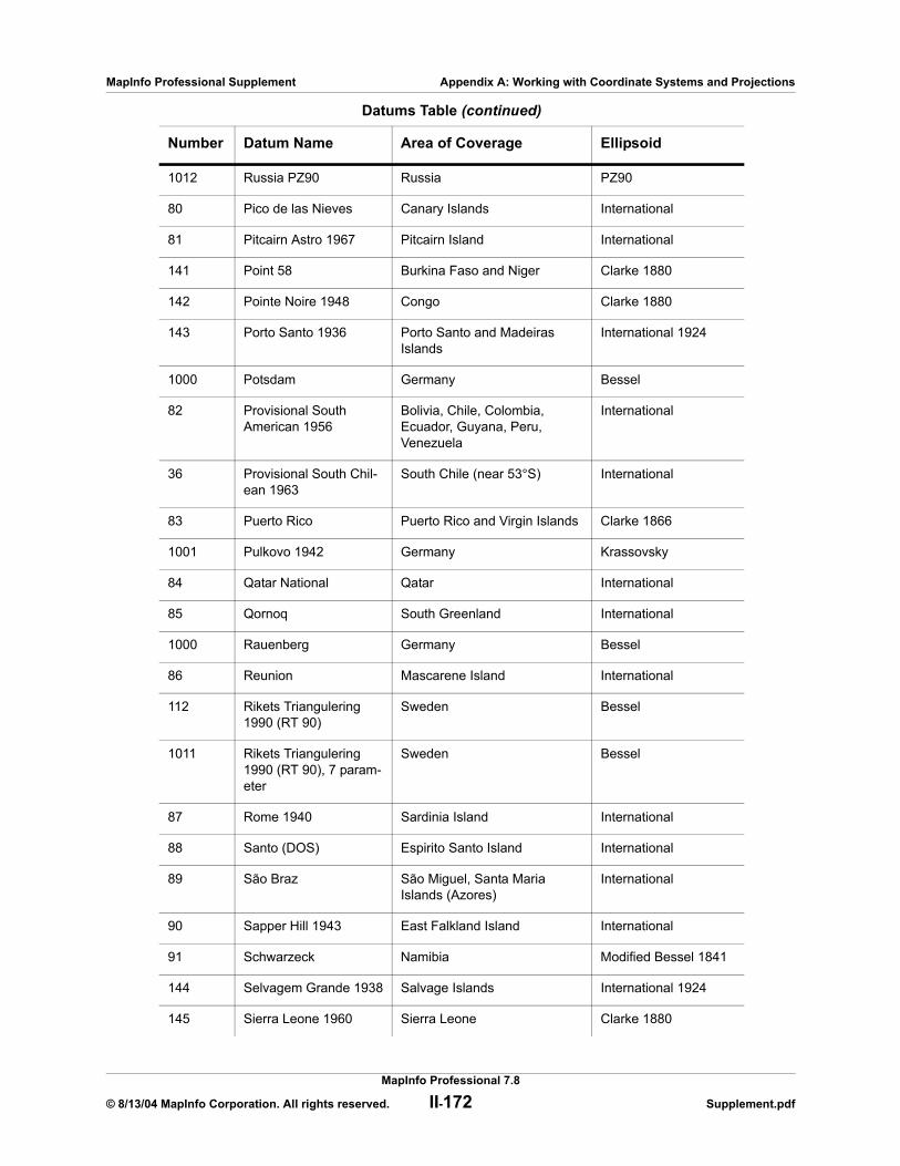
MapInfo Professional Supplement Appendix A: Working with Coordinate Systems and Projections
1012 Russia PZ90 Russia PZ90
80 Pico de las Nieves Canary Islands International
81 Pitcairn Astro 1967 Pitcairn Island International
141 Point 58 Burkina Faso and Niger Clarke 1880
142 Pointe Noire 1948 Congo Clarke 1880
143 Porto Santo 1936 Porto Santo and Madeiras Islands
International 1924
1000 Potsdam Germany Bessel
82 Provisional South American 1956
Bolivia, Chile, Colombia, Ecuador, Guyana, Peru, Venezuela
International
36 Provisional South Chil-ean 1963
South Chile (near 53°S) International
83 Puerto Rico Puerto Rico and Virgin Islands Clarke 1866
1001 Pulkovo 1942 Germany Krassovsky
84 Qatar National Qatar International
85 Qornoq South Greenland International
1000 Rauenberg Germany Bessel
86 Reunion Mascarene Island International
112 Rikets Triangulering 1990 (RT 90)
Sweden Bessel
1011 Rikets Triangulering 1990 (RT 90), 7 param-eter
Sweden Bessel
87 Rome 1940 Sardinia Island International
88 Santo (DOS) Espirito Santo Island International
89 São Braz São Miguel, Santa Maria Islands (Azores)
International
90 Sapper Hill 1943 East Falkland Island International
91 Schwarzeck Namibia Modified Bessel 1841
144 Selvagem Grande 1938 Salvage Islands International 1924
145 Sierra Leone 1960 Sierra Leone Clarke 1880
Datums Table (continued)
Number Datum Name Area of Coverage Ellipsoid
MapInfo Professional 7.8
© 8/13/04 MapInfo Corporation. All rights reserved. II-172 Supplement.pdf

MapInfo Professional Supplement Appendix A: Working with Coordinate Systems and Projections
146 S-JTSK Czech Republic Bessel 1841
1012 Russia SK42 Russia PZ90
1013 Russia SK95 Russia PZ90
92 South American 1969 Argentina, Bolivia, Brazil, Chile, Colombia, Ecuador, Guyana, Paraguay, Peru, Venezuela, Trinidad, and Tobago
South American 1969
93 South Asia Singapore Modified Fischer 1960
94 Southeast Base Porto Santo and Madeira Islands
International
95 Southwest Base Faial, Graciosa, Pico, Sao Jorge, Terceira Islands (Azores)
International
1003 Switzerland (CH 1903) Switzerland Bessel
147 Tananarive Observa-tory 1925
Madagascar International 1924
96 Timbalai 1948 Brunei and East Malaysia (Sarawak and Sabah)
Everest (India 1830)
97 Tokyo Japan, Korea, Okinawa Bessel 1841
98 Tristan Astro 1968 Tristan da Cunha International
99 Viti Levu 1916 Viti Levu Island (Fiji Islands) Clarke 1880
148 Voirol 1874 Tunisia/Algeria Clarke 1880
149 Voirol 1960 Algeria Clarke 1880
100 Wake-Eniwetok 1960 Marshall Islands Hough
101 World Geodetic Sys-tem 1960 (WGS 60)
Worldwide WGS 60
102 World Geodetic Sys-tem 1966 (WGS 66)
Worldwide WGS 66
103 World Geodetic Sys-tem 1972 (WGS 72)
Worldwide WGS 72
104 World Geodetic Sys-tem 1984 (WGS 84)
Worldwide WGS 84
105 Yacare Uruguay International
106 Zanderij Surinam International
Datums Table (continued)
Number Datum Name Area of Coverage Ellipsoid
MapInfo Professional 7.8
© 8/13/04 MapInfo Corporation. All rights reserved. II-173 Supplement.pdf

MapInfo Professional Supplement Appendix A: Working with Coordinate Systems and Projections
UnitsThe following table lists the available measurement units and the number used to identify the unit in the MAPINFOW.PRJ file:
*One International Foot equals exactly 30.48 cm.**One Nautical Mile equals exactly 1852 meters.***One US Survey Foot equals exactly 12/39.37 meters, or approximately 30.48006 cm.
Coordinate System OriginThe coordinate system origin is the point on the Earth (specified as longitude and latitude degrees) from which all coordinate distances are to be measured. X = 0 and Y = 0 at the origin point, unless a false easting and/or false northing is used (see below). It is chosen to optimize the accuracy of a particular coordinate system. As we move north from the origin, Y increases; X increases as we move east. These coordinate values are generally called northings and eastings.
For the Transverse Mercator projection, the origin’s longitude defines the central meridian. In constructing the Transverse Mercator projection a cylinder is positioned tangent to the earth. The central meridian is the line of tangency. The scale of the projected map is true along the central meridian.
In creating a Hotine Oblique Mercator projection it is necessary to specify a great circle that is not the equator nor a meridian. MapInfo Professional does this by specifying one point on the ellipsoid and an azimuth from that point. That point is the origin of the coordinate system.
Units Table
Entry Units
6 Centimeters
31 Chains
3 Feet (also called International Feet)*
2 Inches
1 Kilometers
30 Links
7 Meters
0 Miles
5 Millimeters
9 Nautical Miles**
32 Rods
8 US Survey Feet (used for 1927 State Plane)***
4 Yards
MapInfo Professional 7.8
© 8/13/04 MapInfo Corporation. All rights reserved. II-174 Supplement.pdf
MapInfo Professional Supplement Appendix A: Working with Coordinate Systems and Projections
Standard Parallels (Conic Projections)In conic projections a cone is passed through the earth intersecting it along two parallels of latitude. These are the standard parallels. One is to the north and one is to the south of the projection zone. To use a single standard parallel specify that latitude twice. Both are expressed in degrees of latitude.
Oblique Azimuth (Hotine Oblique Mercator)When specifying a great circle (such as the Hotine Oblique Mercator) using a point and an azimuth (arc), the azimuth is called the Oblique Azimuth and is expressed in degrees.
Scale Factor (Transverse Mercator)A scale factor is applied to cylindrical coordinates to average scale error over the central area of the map while reducing the error along the east and west boundaries. The scale factor has the effect of recessing the cylinder into the earth so that it has two lines of intersection. Scale is true along these lines of intersection.
You may see the scale factor expressed as a ratio, such as 1:25000. In this case it is generally called the scale reduction. The relationship between scale factor and scale reduction is:
scale factor = 1-scale reduction
In this case the scale factor would be 1-(1/25000) or 0.99996.
False Easting and False NorthingAs you can see in the Longitude/Latitude Projection Map on page II-158, X and Y coordinate parameters are commonly designated in relationship to a single point. Points to the left of that center point are negative and points to the right are positive. Points above that center point are positive and points below that point are negative.
In the days of the tall ships, these calculations and computations were done by hand. Using positive and negative signs made these calculations more complicated. The terms “false easting” and “false northing” were used to remove these signs and refer to the absolute value of the X and Y coordinates. Now, MapInfo Professional handles these computations, but these parameters still have to be accounted for in the projections that use them.
Range (Azimuthal Projections)The range specifies, in degrees, how much of the Earth is visible. The range can be between 1 and 180. When you specify 90, you see a hemisphere. When you specify 180 you see the whole earth, though much of it is very distorted.
About Polyconic Coordinate SystemsThe following description has been copied from “Map Projections – A Working Manual”, USGS Professional Paper 1395, by John P. Snyder.
MapInfo Professional 7.8
© 8/13/04 MapInfo Corporation. All rights reserved. II-175 Supplement.pdf

MapInfo Professional Supplement Appendix A: Working with Coordinate Systems and Projections
The Polyconic projection, usually called the American Polyconic in Europe, achieved its name because the curvature of the circular arc for each parallel on the map is the same as it would be following the unrolling of a cone which had been wrapped around the globe tangent to the particular parallel of latitude, with the parallel traced onto the cone. Thus, there are many (”poly-”) cones involved, rather than the single cone of each regular conic projection.
The Polyconic projection is neither equal-area nor conformal. Along the central meridian, however, it is both distortion free and true to scale. Each parallel is true to scale, but the meridians are lengthened by various amounts to cross each parallel at the correct position along the parallel, so that no parallel is standard in the sense of having conformality (or correct angles), except at the central meridian. Near the central meridian, distortion is extremely small.
This projection is not intended for mapping large areas. The conversion algorithms used break down when mapping wide longitude ranges. For example, World.tab, from the sample data shipped with MapInfo Professional, may exhibit anomalies if reprojected using Polyconic.
Examples of Projection Entries in the MAPINFOW.PRJ FileThe MAPINFOW.PRJ file lists the parameters for each coordinate system on a separate line, as in the following examples:
“Mollweide (Equal Area)”, 13, 62, 7, 0“Albers Equal–Area Conic (Alaska)”, 9, 63, 7, –154, 50, 55, 65, 0, 0“UTM Zone 9 (NAD 27 for Canada)”, 8, 66, 7, –129, 0, 0.9996, 500000, 0
This is a basic list of the elements of a coordinate system, for review. Following this list, you can see some entries from the .PRJ file.
1. The first element in each list is the name of the projection in quotes. 2. The second element in each list is the number that identifies the projection type as
indicated in Datums Table on page II-166. 3. The remaining elements in the list are the parameter values for that particular projection.
The elements follow the order as outlined in the table Common Coordinate Systems and their Parameters on page II-162. Each element is separated by a comma.
Let’s look at some specific coordinate systems to prepare you to create your own projection. It is important to remember that the elements of a projection are different for each projection. Here are some examples we have already seen:
Example: “Mollweide (Equal Area)”, 13, 62, 7, 0
where:
Where Refers to: For More Information, See:
“Mollweide (Equal Area)”,
Name of Coordinate System Common Coordinate Systems and their Parameters on page II-162
13, Projection type used MapInfo Professional Projection Types Table on page II-163
62, Datum used Datums Table on page II-166
MapInfo Professional 7.8
© 8/13/04 MapInfo Corporation. All rights reserved. II-176 Supplement.pdf
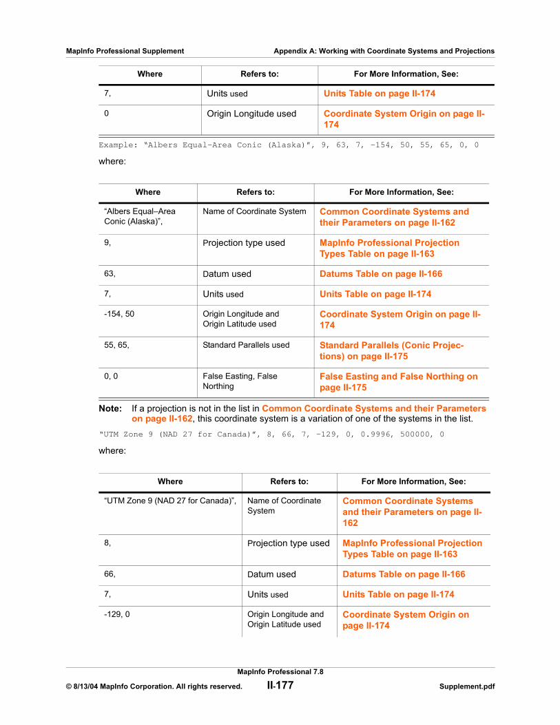
MapInfo Professional Supplement Appendix A: Working with Coordinate Systems and Projections
Example: “Albers Equal–Area Conic (Alaska)”, 9, 63, 7, –154, 50, 55, 65, 0, 0
where:
Note: If a projection is not in the list in Common Coordinate Systems and their Parameters on page II-162, this coordinate system is a variation of one of the systems in the list.
“UTM Zone 9 (NAD 27 for Canada)”, 8, 66, 7, –129, 0, 0.9996, 500000, 0
where:
7, Units used Units Table on page II-174
0 Origin Longitude used Coordinate System Origin on page II-174
Where Refers to: For More Information, See:
“Albers Equal–Area Conic (Alaska)”,
Name of Coordinate System Common Coordinate Systems and their Parameters on page II-162
9, Projection type used MapInfo Professional Projection Types Table on page II-163
63, Datum used Datums Table on page II-166
7, Units used Units Table on page II-174
-154, 50 Origin Longitude and Origin Latitude used
Coordinate System Origin on page II-174
55, 65, Standard Parallels used Standard Parallels (Conic Projec-tions) on page II-175
0, 0 False Easting, False Northing
False Easting and False Northing on page II-175
Where Refers to: For More Information, See:
“UTM Zone 9 (NAD 27 for Canada)”, Name of Coordinate System
Common Coordinate Systems and their Parameters on page II-162
8, Projection type used MapInfo Professional Projection Types Table on page II-163
66, Datum used Datums Table on page II-166
7, Units used Units Table on page II-174
-129, 0 Origin Longitude and Origin Latitude used
Coordinate System Origin on page II-174
Where Refers to: For More Information, See:
MapInfo Professional 7.8
© 8/13/04 MapInfo Corporation. All rights reserved. II-177 Supplement.pdf
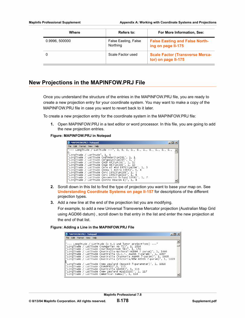
MapInfo Professional Supplement Appendix A: Working with Coordinate Systems and Projections
New Projections in the MAPINFOW.PRJ File
Once you understand the structure of the entries in the MAPINFOW.PRJ file, you are ready to create a new projection entry for your coordinate system. You may want to make a copy of the MAPINFOW.PRJ file in case you want to revert back to it later.
To create a new projection entry for the coordinate system in the MAPINFOW.PRJ file:
1. Open MAPINFOW.PRJ in a text editor or word processor. In this file, you are going to add the new projection entries.
Figure: MAPINFOW.PRJ in Notepad
2. Scroll down in this list to find the type of projection you want to base your map on. See Understanding Coordinate Systems on page II-157 for descriptions of the different projection types.
3. Add a new line at the end of the projection list you are modifying.For example, to add a new Universal Transverse Mercator projection (Australian Map Grid using AGD66 datum) , scroll down to that entry in the list and enter the new projection at the end of that list.
Figure: Adding a Line in the MAPINFOW.PRJ File
0.9996, 500000 False Easting, False Northing
False Easting and False North-ing on page II-175
0 Scale Factor used Scale Factor (Transverse Merca-tor) on page II-175
Where Refers to: For More Information, See:
MapInfo Professional 7.8
© 8/13/04 MapInfo Corporation. All rights reserved. II-178 Supplement.pdf
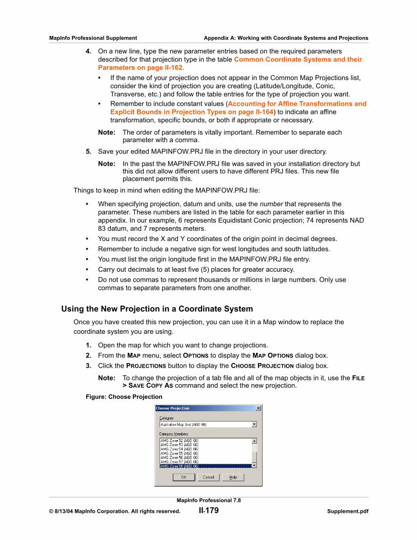
MapInfo Professional Supplement Appendix A: Working with Coordinate Systems and Projections
4. On a new line, type the new parameter entries based on the required parameters described for that projection type in the table Common Coordinate Systems and their Parameters on page II-162. • If the name of your projection does not appear in the Common Map Projections list,
consider the kind of projection you are creating (Latitude/Longitude, Conic, Transverse, etc.) and follow the table entries for the type of projection you want.
• Remember to include constant values (Accounting for Affine Transformations and Explicit Bounds in Projection Types on page II-164) to indicate an affine transformation, specific bounds, or both if appropriate or necessary.
Note: The order of parameters is vitally important. Remember to separate each parameter with a comma.
5. Save your edited MAPINFOW.PRJ file in the directory in your user directory.
Note: In the past the MAPINFOW.PRJ file was saved in your installation directory but this did not allow different users to have different PRJ files. This new file placement permits this.
Things to keep in mind when editing the MAPINFOW.PRJ file:
• When specifying projection, datum and units, use the number that represents the parameter. These numbers are listed in the table for each parameter earlier in this appendix. In our example, 6 represents Equidistant Conic projection; 74 represents NAD 83 datum, and 7 represents meters.
• You must record the X and Y coordinates of the origin point in decimal degrees.• Remember to include a negative sign for west longitudes and south latitudes. • You must list the origin longitude first in the MAPINFOW.PRJ file entry.• Carry out decimals to at least five (5) places for greater accuracy.• Do not use commas to represent thousands or millions in large numbers. Only use
commas to separate parameters from one another.
Using the New Projection in a Coordinate SystemOnce you have created this new projection, you can use it in a Map window to replace the coordinate system you are using.
1. Open the map for which you want to change projections.2. From the MAP menu, select OPTIONS to display the MAP OPTIONS dialog box.3. Click the PROJECTIONS button to display the CHOOSE PROJECTION dialog box.
Note: To change the projection of a tab file and all of the map objects in it, use the FILE > SAVE COPY AS command and select the new projection.
Figure: Choose Projection
MapInfo Professional 7.8
© 8/13/04 MapInfo Corporation. All rights reserved. II-179 Supplement.pdf

MapInfo Professional Supplement Appendix A: Working with Coordinate Systems and Projections
4. Select the new projection from the list and click OK to confirm. The Map Options dialog redisplays.
5. Click OK to implement the new projection in the Map window.
Entering a New Coordinate System (Example)To illustrate this process in another way, create the following coordinate system using these parameters by adding a new entry to the MAPINFOW.PRJ file:
1. Open MAPINFOW.PRJ in a text editor or word processor.2. Go to the Equidistant Conic section and add a new line.3. Type the name of your new coordinate system in quotes, followed by a comma.4. Enter the following information to represent your coordinate system:
6, 74, 7, -90.5, 30, 10.33333, 50, 10000000, 500000
5. Save your edited MAPINFOW.PRJ file.
You can now use your custom coordinate system just as you would use any of the coordinate systems that come with MapInfo.
There are other ways you can edit this file. To shorten the list, remove coordinate systems from the file. You can also change the names, change group headings and reorder the file to suit your needs.
Note: Group headings are distinguished by the hyphen at the beginning of the name. Names of coordinate systems cannot begin with a hyphen or a space.
Parameter Type Entry Description
Name “Equidistant Conic Plus” Name of the new coordinate system
Projection Type 6, Equidistant Conic
Datum 74, (NAD 83)
Units 7, meters
Origin Longitude -90.5, 90°30′W
Origin Latitude 30, 30°N,
Standard Parallel 1 10.33333, 10°20′N
Standard Parallel 2 50, 50°N
False Easting 10000000, 10,000,000 m
False Northing 500000 500,000 m
MapInfo Professional 7.8
© 8/13/04 MapInfo Corporation. All rights reserved. II-180 Supplement.pdf
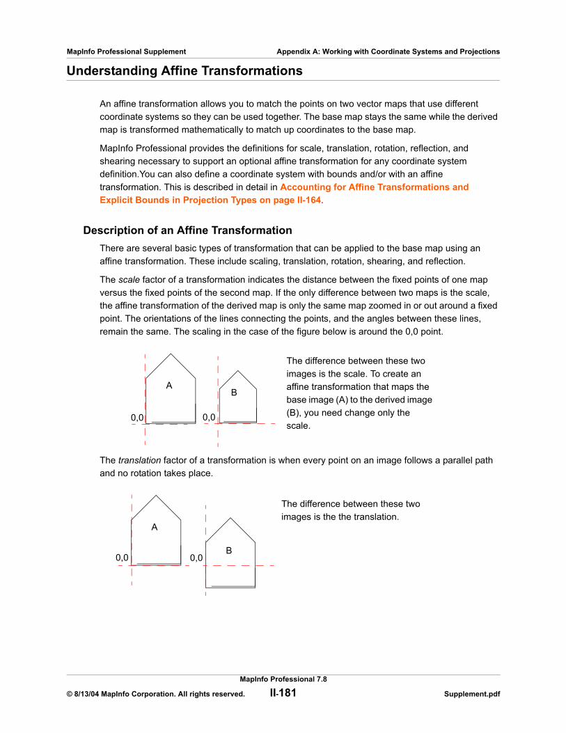
MapInfo Professional Supplement Appendix A: Working with Coordinate Systems and Projections
Understanding Affine Transformations
An affine transformation allows you to match the points on two vector maps that use different coordinate systems so they can be used together. The base map stays the same while the derived map is transformed mathematically to match up coordinates to the base map.
MapInfo Professional provides the definitions for scale, translation, rotation, reflection, and shearing necessary to support an optional affine transformation for any coordinate system definition.You can also define a coordinate system with bounds and/or with an affine transformation. This is described in detail in Accounting for Affine Transformations and Explicit Bounds in Projection Types on page II-164.
Description of an Affine TransformationThere are several basic types of transformation that can be applied to the base map using an affine transformation. These include scaling, translation, rotation, shearing, and reflection.
The scale factor of a transformation indicates the distance between the fixed points of one map versus the fixed points of the second map. If the only difference between two maps is the scale, the affine transformation of the derived map is only the same map zoomed in or out around a fixed point. The orientations of the lines connecting the points, and the angles between these lines, remain the same. The scaling in the case of the figure below is around the 0,0 point.
The translation factor of a transformation is when every point on an image follows a parallel path and no rotation takes place.
The difference between these two images is the scale. To create an affine transformation that maps the base image (A) to the derived image (B), you need change only the scale.
AB
0,0 0,0
The difference between these two images is the the translation.
A
B0,0 0,0
MapInfo Professional 7.8
© 8/13/04 MapInfo Corporation. All rights reserved. II-181 Supplement.pdf
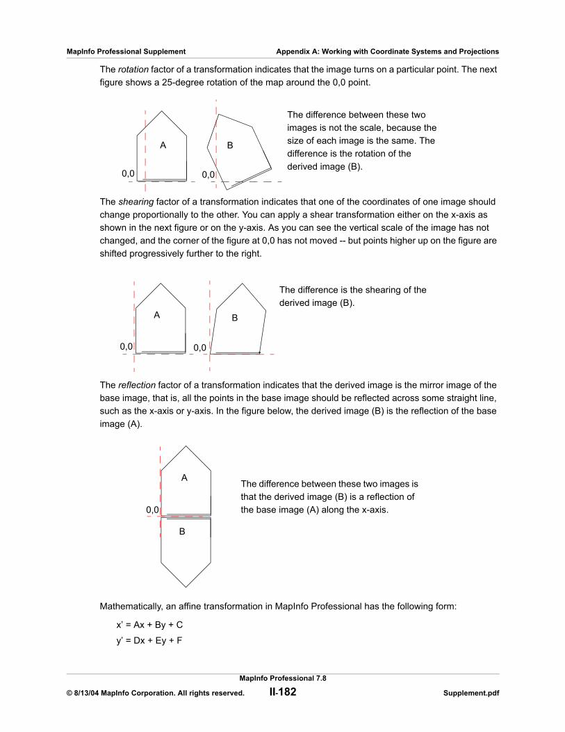
MapInfo Professional Supplement Appendix A: Working with Coordinate Systems and Projections
The rotation factor of a transformation indicates that the image turns on a particular point. The next figure shows a 25-degree rotation of the map around the 0,0 point.
The shearing factor of a transformation indicates that one of the coordinates of one image should change proportionally to the other. You can apply a shear transformation either on the x-axis as shown in the next figure or on the y-axis. As you can see the vertical scale of the image has not changed, and the corner of the figure at 0,0 has not moved -- but points higher up on the figure are shifted progressively further to the right.
The reflection factor of a transformation indicates that the derived image is the mirror image of the base image, that is, all the points in the base image should be reflected across some straight line, such as the x-axis or y-axis. In the figure below, the derived image (B) is the reflection of the base image (A).
Mathematically, an affine transformation in MapInfo Professional has the following form:
x’ = Ax + By + C
y’ = Dx + Ey + F
The difference between these two images is not the scale, because the size of each image is the same. The difference is the rotation of the derived image (B).
A B
0,0 0,0
The difference is the shearing of the derived image (B).
A B
0,0 0,0
The difference between these two images is that the derived image (B) is a reflection of the base image (A) along the x-axis.
A
0,0
B
MapInfo Professional 7.8
© 8/13/04 MapInfo Corporation. All rights reserved. II-182 Supplement.pdf
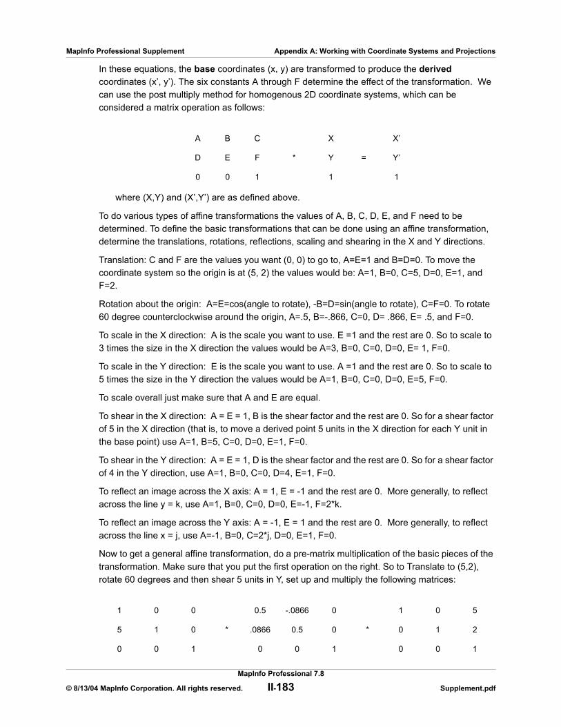
MapInfo Professional Supplement Appendix A: Working with Coordinate Systems and Projections
In these equations, the base coordinates (x, y) are transformed to produce the derived coordinates (x’, y’). The six constants A through F determine the effect of the transformation. We can use the post multiply method for homogenous 2D coordinate systems, which can be considered a matrix operation as follows:
where (X,Y) and (X’,Y’) are as defined above.
To do various types of affine transformations the values of A, B, C, D, E, and F need to be determined. To define the basic transformations that can be done using an affine transformation, determine the translations, rotations, reflections, scaling and shearing in the X and Y directions.
Translation: C and F are the values you want (0, 0) to go to, A=E=1 and B=D=0. To move the coordinate system so the origin is at (5, 2) the values would be: A=1, B=0, C=5, D=0, E=1, and F=2.
Rotation about the origin: A=E=cos(angle to rotate), -B=D=sin(angle to rotate), C=F=0. To rotate 60 degree counterclockwise around the origin, A=.5, B=-.866, C=0, D= .866, E= .5, and F=0.
To scale in the X direction: A is the scale you want to use. E =1 and the rest are 0. So to scale to 3 times the size in the X direction the values would be A=3, B=0, C=0, D=0, E= 1, F=0.
To scale in the Y direction: E is the scale you want to use. A =1 and the rest are 0. So to scale to 5 times the size in the Y direction the values would be A=1, B=0, C=0, D=0, E=5, F=0.
To scale overall just make sure that A and E are equal.
To shear in the X direction: A = E = 1, B is the shear factor and the rest are 0. So for a shear factor of 5 in the X direction (that is, to move a derived point 5 units in the X direction for each Y unit in the base point) use A=1, B=5, C=0, D=0, E=1, F=0.
To shear in the Y direction: A = E = 1, D is the shear factor and the rest are 0. So for a shear factor of 4 in the Y direction, use A=1, B=0, C=0, D=4, E=1, F=0.
To reflect an image across the X axis: A = 1, E = -1 and the rest are 0. More generally, to reflect across the line y = k, use A=1, B=0, C=0, D=0, E=-1, F=2*k.
To reflect an image across the Y axis: A = -1, E = 1 and the rest are 0. More generally, to reflect across the line x = j, use A=-1, B=0, C=2*j, D=0, E=1, F=0.
Now to get a general affine transformation, do a pre-matrix multiplication of the basic pieces of the transformation. Make sure that you put the first operation on the right. So to Translate to (5,2), rotate 60 degrees and then shear 5 units in Y, set up and multiply the following matrices:
A B C X X’
D E F * Y = Y’
0 0 1 1 1
1 0 0 0.5 -.0866 0 1 0 5
5 1 0 * .0866 0.5 0 * 0 1 2
0 0 1 0 0 1 0 0 1
MapInfo Professional 7.8
© 8/13/04 MapInfo Corporation. All rights reserved. II-183 Supplement.pdf

MapInfo Professional Supplement Appendix A: Working with Coordinate Systems and Projections
Multiplying these out gives the following matrix:
Therefore, the required values are: A=.5, B=-.866, C=0.768, D=3.366, E=-3.83, F=9.17.
Note: When using affine transformation values in projection definitions or .MIF file COORDSYS settings, you may need to calculate the *inverse* of an affine transformation. This is because if a table displays in a projection that includes an affine transformation, MapInfo Professional transforms the coordinate system, not the objects in the table!
Frequently Asked Questions
What do the \p#### codes mean in the MAPINFOW.PRJ file?e.g.: ”— Australian Map Grid (AGD 66) —”
”AMG Zone 47 (AGD 66)”, 8, 12, 7, 99, 0, 0.9996, 500000, 10000000
”AMG Zone 48 (AGD 66)\p20248”, 8, 12, 7, 105, 0, 0.9996, 500000, 10000000
Answer: MapInfo Professional uses the \p#### or Projected Coordinate System (PCS) codes shown in the above example when registering GeoTIFF images or other georeferenced raster images. GeoTIFF files often identify their coordinate system with a single code number instead of listing the coordinate system parameters, so MapInfo Professional scans the MAPINFOW.PRJ file to find a matching supported code. MapInfo Professional supports a subset of PCS codes, depending on the projection they use, in values between 20000 and 32760). Codes cannot be used more than once in the MAPINFOW.PRJ file.
Note: WMS tables (and WFS) also use these \p#### codes in mapinfow.prj file entries to determine correct coordinate system to use.
For more information about GeoTIFF files and PCS codes, see this web page:
http://www.remotesensing.org/geotiff/geotiff.html
How do I convert a coordinate system with units in meters to feet?
Answer: You will need to edit the MAPINFOW.PRJ file to modify the same projection in a different measurement system and adjust the False Eastings and Northings used for the difference.
For example below, the first line is the original projection expressed in meters. The second line is a copied modification of the first, where the units were changed from ”7” (meters) to ”8” (feet) indicating this coordinate system is now using feet, and the False Easting (2000000) and Northing (500000) components were divided by .3048 to convert them from meters to feet.
Example:
”California, Zone I (1983)\p26941”, 3, 74, 7, -122, 39.3333333333, 40,
41.6666666667, 2000000, 500000
0.5 -0.866 0.768
3.366 -3.83 9.17
0 0 1
MapInfo Professional 7.8
© 8/13/04 MapInfo Corporation. All rights reserved. II-184 Supplement.pdf
MapInfo Professional Supplement Appendix A: Working with Coordinate Systems and Projections
”California, Zone I FT (1983)\p26941”, 3, 74, 8 , -122, 39.3333333333, 40,
41.6666666667, 6561679.7, 164041.99
I chose Longitude/Latitude (NAD 83) as my projection; however, whenever I look at the Choose Projection dialog, it keeps saying Longitude/Latitude (GRS 80). Why won’t my projection change?
Answer: The GRS 80 datum is identical to NAD 83 datum. MapInfo Professional uses the numeric parameters, not the name, to decide which coordinate system to highlight in the Choose Projection dialog. Since GRS 80 has the same numeric parameters as NAD 83, and GRS 80 datum comes earlier in the list, MapInfo Professional chooses GRS 80 instead of NAD 83.
For More Information
The first three publications listed below are relatively short pamphlets. The last two are substantial books. We’ve also given addresses and phone numbers for the American Congress of Surveying and Mapping (the pamphlets) and the U.S. Geological Survey (the books).
• American Cartographic Association. Choosing a World Map—Attributes, Distortions, Classes, Aspects. Falls Church, VA: American Congress on Surveying and Mapping. Special Publication No. 2. 1988.
• American Cartographic Association. Which Map is Best? Projections for World Maps. Falls Church, VA.: American Congress on Surveying and Mapping. Special Publication No. 1. 1986.
• John P. Snyder. Map Projections—A Working Manual. Washington: U.S. Geological Survey Professional Paper 1395. 1987
• John P. Snyder and Philip M. Voxland. An Album of Map Projections. Washington: U.S. Geological Survey Professional Paper 1453. 1989.
Contact InformationThe Department of Geography at the University of Colorado at Boulder has made available "The Geographer's Craft" project, a website devoted to explanations of map projections, geodetic datums, and coordinate systems. It is particularly valuable because many of the explanations are presented using MapInfo Professional. The materials may be used for study, research, and education. If you link to or cite the materials below, please credit the author: Peter H. Dana, The Geographer's Craft Project, Department of Geography, The University of Colorado at Boulder.
For geodetic datum information and explanations, go to:
http://www.colorado.edu/geography/gcraft/notes/datum/datum.html
For information on coordinate systems and associated topics, go to:
http://www.colorado.edu/geography/gcraft/notes/coordsys/coordsys.html
For information on map projections, go to:
http://www.colorado.edu/geography/gcraft/notes/mapproj/mapproj.html
MapInfo Professional 7.8
© 8/13/04 MapInfo Corporation. All rights reserved. II-185 Supplement.pdf

B
High-Resolution Custom SymbolsMapInfo provides new high-resolution (24-bit color) custom symbols.
The destination CustSymb directory is determined by the during installation. If you executed the MapBasic command to reload custom symbols from a particular directory, then the Add Custom Symbols dialog box will add to that directory instead. See the Reload Symbols statement in the MapBasic Reference Guide, Version 7.8.
Sections in this Appendix:
New High Resolution Custom Symbols . . . . . . . . . . . . . . . . . II-187Enhanced High Resolution Custom Symbols . . . . . . . . . . . . II-189
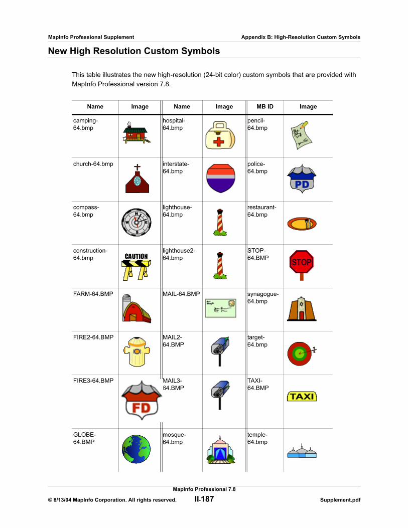
MapInfo Professional Supplement Appendix B: High-Resolution Custom Symbols
New High Resolution Custom Symbols
This table illustrates the new high-resolution (24-bit color) custom symbols that are provided with MapInfo Professional version 7.8.
Name Image Name Image MB ID Image
camping-64.bmp
hospital-64.bmp
pencil-64.bmp
church-64.bmp interstate-64.bmp
police-64.bmp
compass-64.bmp
lighthouse-64.bmp
restaurant-64.bmp
construction-64.bmp
lighthouse2-64.bmp
STOP-64.BMP
FARM-64.BMP MAIL-64.BMP synagogue-64.bmp
FIRE2-64.BMP MAIL2-64.BMP
target-64.bmp
FIRE3-64.BMP MAIL3-64.BMP
TAXI-64.BMP
GLOBE-64.BMP
mosque-64.bmp
temple-64.bmp
MapInfo Professional 7.8
© 8/13/04 MapInfo Corporation. All rights reserved. II-187 Supplement.pdf
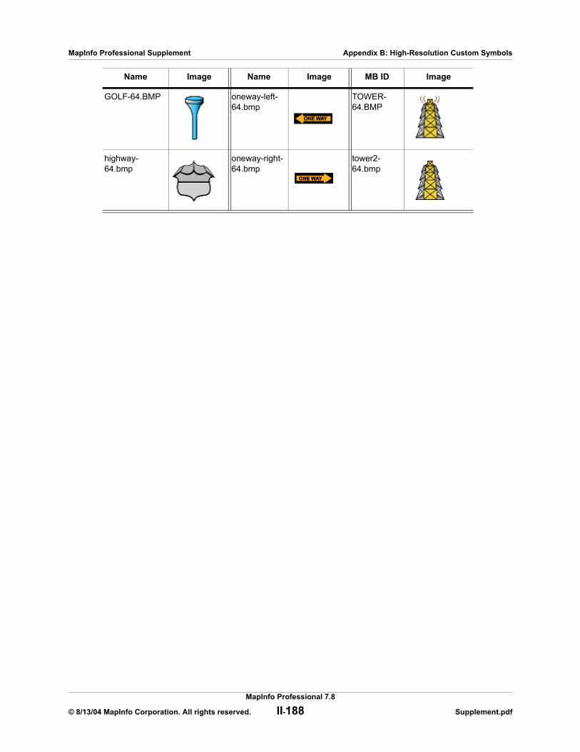
MapInfo Professional Supplement Appendix B: High-Resolution Custom Symbols
GOLF-64.BMP oneway-left-64.bmp
TOWER-64.BMP
highway-64.bmp
oneway-right-64.bmp
tower2-64.bmp
Name Image Name Image MB ID Image
MapInfo Professional 7.8
© 8/13/04 MapInfo Corporation. All rights reserved. II-188 Supplement.pdf
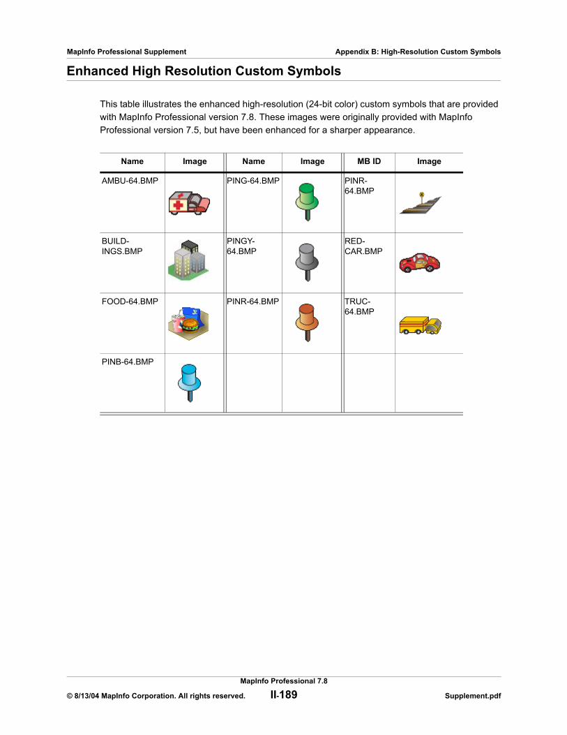
MapInfo Professional Supplement Appendix B: High-Resolution Custom Symbols
Enhanced High Resolution Custom Symbols
This table illustrates the enhanced high-resolution (24-bit color) custom symbols that are provided with MapInfo Professional version 7.8. These images were originally provided with MapInfo Professional version 7.5, but have been enhanced for a sharper appearance.
Name Image Name Image MB ID Image
AMBU-64.BMP PING-64.BMP PINR-64.BMP
BUILD-INGS.BMP
PINGY-64.BMP
RED-CAR.BMP
FOOD-64.BMP PINR-64.BMP TRUC-64.BMP
PINB-64.BMP
MapInfo Professional 7.8
© 8/13/04 MapInfo Corporation. All rights reserved. II-189 Supplement.pdf

C
New and Enhanced MapBasic Statements and FunctionsThese are the new statements and functions available for the MapInfo Professional 7.8 product.
Sections in this Appendix:
New statements and functionsMGRSToPoint Statement . . . . . . . . . . . . . . . . . . . . . . . . . . . . . II-191PointToMGRS Statement . . . . . . . . . . . . . . . . . . . . . . . . . . . . . II-191Objects Pline Statement. . . . . . . . . . . . . . . . . . . . . . . . . . . . . . II-192Save MWS Statement . . . . . . . . . . . . . . . . . . . . . . . . . . . . . . . . II-193WFS Refresh Statement . . . . . . . . . . . . . . . . . . . . . . . . . . . . . . II-194
Enhanced statementsCreate Cartographic Legend Statement . . . . . . . . . . . . . . . . . II-194Export Statement . . . . . . . . . . . . . . . . . . . . . . . . . . . . . . . . . . . II-195LegendInfo() . . . . . . . . . . . . . . . . . . . . . . . . . . . . . . . . . . . . . . . II-196Objects Snap Statement. . . . . . . . . . . . . . . . . . . . . . . . . . . . . . II-196PrintWin Statement. . . . . . . . . . . . . . . . . . . . . . . . . . . . . . . . . . II-196Register Table Statement. . . . . . . . . . . . . . . . . . . . . . . . . . . . . II-197Set Cartographic Legend Statement. . . . . . . . . . . . . . . . . . . . II-197Shade Statement. . . . . . . . . . . . . . . . . . . . . . . . . . . . . . . . . . . . II-197TableInfo() . . . . . . . . . . . . . . . . . . . . . . . . . . . . . . . . . . . . . . . . . II-198

MapInfo Professional Supplement Appendix C: New and Enhanced MapBasic Statements and Functions
MGRSToPoint StatementPurpose
Converts a string representing an MGRS coordinate to an object value representing a point.
SyntaxMGRSToPoint (string)
Return Value
Object
Exampledim x,y As Floatdim obj as Object dim s_mgrs As String dim obj2 as Object
x = -74.669y = 43.263obj = CreatePoint(x, y)
s_mgrs = PointToMGRS$(obj)
obj2 = MGRSToPoint(s_mgrs)
PointToMGRS StatementPurpose
Converts an object value representing a point to a string representing an MGRS coordinate.
SyntaxPointToMGRS$ (inputobject)
Return Value
String
Exampledim x,y As Floatdim obj as Object dim s_mgrs As String dim obj2 as Object
x = -74.669y = 43.263obj = CreatePoint(x, y)
s_mgrs = PointToMGRS$(obj)
obj2 = MGRSToPoint(s_mgrs)
MapInfo Professional 7.8
© 8/13/04 MapInfo Corporation. All rights reserved. II-191 Supplement.pdf

MapInfo Professional Supplement Appendix C: New and Enhanced MapBasic Statements and Functions
Objects Pline StatementPurpose
Splits a single section polyline into two polylines.
SyntaxObjects Pline Split At Node index [IntoTable name][Data column_name = expression]
[ , column_name = expression ... ] ]
Return Value
Object
Description
If an object is a single section polyline, then two new single section polyline objects are created in the output table. The Node index should be a valid MapBasic index for the polyline to be split. If Node is a start or end node for the polyline, the operation is cancelled and an error message is displayed.
The optional Data clause controls what values are stored in the columns of the output objects. The Data clause can contain a comma-separated list of column assignments. Each column assignment can take one of the forms listed in the following table:
The Data clause can contain an assignment for every column in the table. If the Data clause only specifies assignments for some of the columns, blank values are assigned to those columns that are not listed in the Data clause.
If you omit the Data clause entirely, all columns are blanked out of the target objects, storing zero values in numeric columns and blank values in character columns.
Example
You would typically split a polyline through the graphical user interface, but an equivalent MapBasic syntax might appear as follows.
Objects Pline Split At Node 12 Into Table WORLDData Country=Country,Capital=Capital,...
Assignment Effect
col_name = col_name Does not alter the value stored in the column.
col_name = value Stores a specific value in the column. If the column is a character column the value can be a string; if the column is a numeric col-umn, the value can be a number.
MapInfo Professional 7.8
© 8/13/04 MapInfo Corporation. All rights reserved. II-192 Supplement.pdf
MapInfo Professional Supplement Appendix C: New and Enhanced MapBasic Statements and Functions
Save MWS Statement Purpose
The Save MWS statement allows you to save the current workspace as an XML-based MWS file for use with MapXtreme 2004 applications. These MWS files can be shared across platforms in ways that workspaces cannot.
Syntax
Save MWS Window ( window_id [ , window_id ... ] ) Default default_window_id As filespec
window_id is an Integer window identifier for a Map window
default_window_id is an Integer window identifier for the Map window to be recorded in the MWS as the default map.
DescriptionMapInfo Professional enables you to save the maps in your workspace to an XML format for use with MapXtreme 2004 applications. When saving a workspace to MWS format, only the map windows and legends are saved. All other windows are discarded as MapXtreme 2004 applications cannot read that information. Once your workspace is saved in this format, it can be opened with the Workspace Manager utility that is included in the MapXtreme 2004 installation or with an application developed using MapXtreme 2004. The file is valid XML so can also be viewed using any XML viewer or editor. MWS files created with MapInfo Professional 7.8 can be validated using schemas supplied with MapXtreme 2004.
Note: You will not be able to read files saved in MWS format in MapInfo Professional 7.8.
In MapInfo Professional, you can set the visibility of a modifier theme without regard to its reference feature layer, so you can turn the visibility of the main reference layer off but still display the theme. In MapXtreme2004, the modifier themes (Dot Density, Ranges, Individual Value) are only drawn if the reference feature layer is visible. To ensure that modifiers marked as visible in MapInfo Professional display in tools like Workspace Manager, we force the visibility of the reference feature layer so that its modifier themes display.
What is Saved in the MWSThe following information is included in the MWS workspace file:
• Tab files’ name and alias• Coordsys information• Map center and zoom settings• Layer list with implied order• Map size as pixel width and height• Map resize method• Style overrides• Raster layer overrides• Label and label edit information• Individual value themes• Dot density themes
MapInfo Professional 7.8
© 8/13/04 MapInfo Corporation. All rights reserved. II-193 Supplement.pdf
MapInfo Professional Supplement Appendix C: New and Enhanced MapBasic Statements and Functions
• Graduated symbol themes• Bar themes• Range themes• Pie themes• Grid themes as MapXtreme 2004 grid layers with a style override • Themes and label expressions based upon a single attribute column.
What is Not Saved to the MWSThe following information is not saved in the MWS workspace file:
• Any non-map windows (browsers, charts, redistricters, 3D map windows, Prism maps)• Distance, area, or XY and military grid units• Snap mode, autoscroll, and smart pan settings• Printer setup information• Any table that is based on a query• Any theme that is generated from a complex expression
Note: A complex expression includes any operator or multiple referenced tables.
• Any queries• Export options• Line direction arrows• Whether object nodes are drawn or not• Hot links for labels and objects
WFS Refresh StatementPurpose
The WFS Refresh Table statement refreshes a WFS table from the server.
SyntaxWFS Refresh Table alias
ExampleWFS Refresh Table watershed
Create Cartographic Legend StatementThe Create Cartographic Legend statement has a new clause that creates the small or large legend sample size.
Purpose
The Create Cartographic Legend statement allows you to create and display cartographic style legends as well as theme legends for an active map window.
Syntax
The new clause in the syntax is indicated in bold.
Create Cartographic Legend [ Style Size {Small | Large}
The full syntax is described in the MapBasic Reference Guide, Version 7.8.
MapInfo Professional 7.8
© 8/13/04 MapInfo Corporation. All rights reserved. II-194 Supplement.pdf

MapInfo Professional Supplement Appendix C: New and Enhanced MapBasic Statements and Functions
Export StatementPurpose
Exports a table to another file format.
Syntax 1 (for exporting MIF/MID files, DBF files, ASCII text files or CSV files)Export table
Into file_name [Type
{ "MIF" |
"DBF" [ Charset char_set ] |
"ASCII" [ Charset char_set ] [ Delimiter "d " ] [ Titles ] } ]
"CSV" [Charset char_set ] [ Titles ] } ]
[ Overwrite ]
Syntax 2 (for exporting DXF files)Export table
Into file_name [ Type "DXF" ] [ Overwrite ][ Preserve
[ AttributeData ] [ Preserve ] [ MultiPolygonRgns [ As Blocks ] ] ]
[ { Binary | ASCII [ DecimalPlaces decimal_places ] } ][ Version { 12 | 13 } ] [ Transform
( MI_x1 , MI_y1 ) ( MI_x2 , MI_y2 )
( DXF_x1 , DXF_y1 ) ( DXF_x2 , DXF_y2 ) ]
table is the name of an open table; do not use quotation marks around this name
file_name is a String specifying the filename to contain the exported data; if the file name does not include a path, the export file is created in the current working directory
char_set is a String that identifies a character set, such as "WindowsLatin1"; see the separate CharSet discussion for details
d is a character used as a delimiter when exporting an ASCII file
decimal_places is a small integer (from 0 to 16, default value is 6), which controls the number of decimal places used when exporting floating-point numbers in ASCII
MI_x1, MI_y1, etc. are numbers that represent bounds coordinates in the MapInfo table
DXF_x1, DXF_y1, etc. are numbers that represent bounds coordinates in the DXF file
Description
The Export statement copies the contents of a MapInfo table to a separate file, using a file format which other packages could then edit or import. For example, you could export the contents of a table to a DXF file, then use a CAD software package to import the DXF file. The Export statement does not alter the original table.
Further details are available in the MapBasic Help System and in the MapBasic Reference Guide.
MapInfo Professional 7.8
© 8/13/04 MapInfo Corporation. All rights reserved. II-195 Supplement.pdf
MapInfo Professional Supplement Appendix C: New and Enhanced MapBasic Statements and Functions
LegendInfo()The LegendInfo() function has a new LEGEND_INFO_STYLE_SAMPLE_SIZE attribute that returns the legend size information.
Purpose
Returns information about a legend.
Syntax LegendInfo( window_id, attribute )
The new attribute is:
LEGEND_INFO_STYLE_SAMPLE_SIZE
This attribute returns 0 for small legend sample style or 1 for large legend sample style.
The full syntax is described in the MapBasic Reference Guide, Version 7.8.
ExampleLegendInfo(FrontWindow() LEGEND_INFO_STYLE_SAMPLE_SIZE)
Objects Snap StatementPurpose
Cleans the objects from the given table, and optionally performs various topology-related operations on the objects, including snapping nodes from different objects that are close to each other into the same location and generalization/thinning.
New for MapBasic 7.8: The settings specified in the Objects Snap statement are written to the input table’s metadata when the Objects Snap statement is executed. These settings become the default values for the table when the Set Values for Node Snap and Thinning dialog box is opened.
For more information about this statement, see the MapBasic Reference Guide.
PrintWin StatementThe MapBasic PrintWin statement has been enhanced so that a MapInfo window can be printed to a file.
Purpose
Prints an existing window.
Syntax PrintWin [ Window window_id ] [ Interactive ] [ File output_filename] [Overwrite ]
Description
The PrintWin statement prints a window.
If the statement includes the optional Window clause, MapBasic prints the specified window; otherwise, MapBasic prints the active window.
MapInfo Professional 7.8
© 8/13/04 MapInfo Corporation. All rights reserved. II-196 Supplement.pdf
MapInfo Professional Supplement Appendix C: New and Enhanced MapBasic Statements and Functions
The window_id parameter represents a window identifier; see the FrontWindow( ) and WindowInfo( ) functions for more information about obtaining window identifiers.
If you include the Interactive keyword, MapInfo Professional displays the Print dialog. If you omit the Interactive keyword, MI Pro prints the window automatically, without displaying the dialog.
ExamplePrintWin Window FrontWindow() File "c:\output\file.plt"
Register Table StatementWhen opening an Excel spreadsheet, the user can now specify how each column is imported. For example, the user might want a 'Date' column in Excel to be a Text column in MapInfo Professional. The MapBasic Register Table statement has been enhanced to support this new feature,
Syntax
When the Interactive keyword is specified for type XLS, it instructs the interface to display the Set Field Properties window when importing Excel files. The following illustrates the changes to the Register Table syntax that support this new feature.
Register Table source_file Type “XLS” [ Titles ] [ Range range_name ] [Interactive]
The full syntax is described in the MapBasic Reference Guide, Version 7.8.
Set Cartographic Legend StatementThe Set Cartographic Legend statement now allows you to control the sample legend sizes that appear in Cartographic Legend windows.
Purpose
The Set Cartographic Legend statement allows you to set redraw functionality on or off, refresh, set the orientation to portrait or landscape, select small or large sample legend sizes, or change the frame order of an existing cartographic legend.
Syntax
The change from the previous syntax is indicated in bold.
Set Cartographic Legend [ Window legend_window_id ][ Refresh ][ Portrait | Landscape ][ Align][ Style Size {Small | Large}] [ Frame Order { frame_id, frame_id, frame_id, ... } ]
The full syntax is described in the MapBasic Reference Guide, Version 7.8.
Shade StatementThe MapBasic Shade statement now allows for circle/square dot density thematics with user-defined size.
MapInfo Professional 7.8
© 8/13/04 MapInfo Corporation. All rights reserved. II-197 Supplement.pdf

MapInfo Professional Supplement Appendix C: New and Enhanced MapBasic Statements and Functions
Purpose
Creates a thematic map layer and adds it to an existing Map window.
Syntax
The MapBasic Shade statement now allows for circle/square dot density thematics with user defined size. The following illustrates the changes to the Density and Width parts of the MapBasic syntax that support this new feature.
Shade[ Window window_id ] { layer_id | layer_name } With expr Density dot_value {Circle | Square} Width dot_size[ Color color ]
The full syntax is described in the MapBasic Reference Guide, Version 7.8. For backwards compatibility, the older MapBasic syntax (version 7.5 or earlier) is still supported.
Description
For Circle dot style, the dot_size can be 2 to 25 pixels in width. For Square dot style, the dot_size can be 1 to 25 pixels.
The keyword Width is followed by dot_size. This specifies how large the dots should be, in terms of pixels.
The optional Color clause is used to set the color of the dots.
Example
The following example creates a dot density map using the States table’s Num_HH_90 column (which in this case indicates the number of households per state, circa 1990). The resultant dot density map will show many 4-pixel dots; each dot representing 60,000 households.
shade window 176942288 7 with Pop_1990 density 600000 circle width 4 color 255
TableInfo()The MapBasic TableInfo() variable includes a new value for the TAB_INFO_TYPE attribute to support Web Feature Service (WFS).
Purpose
Returns information about an open table.
Syntax
TableInfo( table_id , attribute )
The new return value for the TAB_INFO_TYPE attribute is:
TAB_TYPE_WFS
This return value indicates that the table is from a Web Feature Service.
The full syntax is described in the MapBasic Reference Guide, Version 7.8.
MapInfo Professional 7.8
© 8/13/04 MapInfo Corporation. All rights reserved. II-198 Supplement.pdf

MapInfo Professional Supplement Appendix C: New and Enhanced MapBasic Statements and Functions
MapInfo Professional 7.8
© 8/13/04 MapInfo Corporation. All rights reserved. II-199 Supplement.pdf
GL
Glossary of TermsAffine TransformationThe mathematical calculation required to align two vector maps that use different coordinate systems.
AliasThe name assigned to an expression or a column when you are working in the Select Columns field in the SQL Select dialog box. This name appears as the column title for that expression or column in a Browser.
ApplicationA computer program used for a particular kind of work, such as word processing. Application is often interchangeable with the word program.
ASCIIThe acronym for American Standard Code for Information Interchange. ASCII is a standard code used in most microcomputers, computer terminals, and printers for representing characters as numbers. It not only includes printable characters, but also control codes to indicate carriage return, backspace, and so forth.
AxisUsed in a graph, these are graduated lines bordering the plot area of a graph. Location coordinates are measured relative to the axes. By convention the X-axis is horizontal, the Y-axis is vertical.
Bar Chart MapA type of thematic map that displays a bar chart of thematic variables for each record in a table from which the map is based.
MapInfo Professional Supplement Glossary of Terms
Base MapUsually the dominant or underlying layer in a given map. (These are typically the data layers that MapInfo® offers as ready products.) Users usually layer their own data on top of these base maps or use these base maps to geocode or to make new layers. Examples are joining industry data to postal code boundaries for analysis and then combining arrangements of the postal codes into new territory layers.
Base TableA permanent table, which is part of a map, as opposed to a query table, which is temporary. You can edit the contents of base tables, and you can change their structure (by editing, deleting, reordering columns and adding or deleting graphic objects). See Query Table on page 210.
BitmapA screen image displayed as an array of dots or bits. Software usually generates either bit-mapped (raster) or object-oriented (vectored) files. MapInfo can work with both.
Boundary RegionIn GIS a boundary is a region on a map enclosed by a border. Cambria County, Manitoba, and Argentina would all be represented as boundaries on a map. Note that a single boundary could encompass several polygons. Thus, Indonesia is a single boundary but consists of many polygons.
BrowserA window for viewing a table (or database, spreadsheet or text file) in tabular form.
Buffer A type of proximity analysis where areas or zones of a given distance are generated around selected map objects. Buffers are user-defined or can be generated for a set of objects based on those objects’ attribute values. The resulting buffer zones form region objects representing the area that is within the specified buffer distance from the object.
CadastralA map set used to graphically define the cadastre or land ownership in a given area. A tax map is an example of a cadastral map. The land registration, assessment roles, and tax maps comprise the cadastre.
CartesianA coordinate system using an x,y scale not tied to any “real-world” system. Most CAD drawing uses this method of registering objects (e.g., a drawing of a ball-bearing assembly, floor plans). If a drawing uses Cartesian coordinates, one corner of the drawing probably has coordinates 0, 0.
Cartesian CoordinatesThe conventional representation of geometric objects by x and y values on a plane.
MapInfo Professional 7.5/7.8
© 8/13/04 MapInfo Corporation. All rights reserved. 201 Supplement.pdf

MapInfo Professional Supplement Glossary of Terms
Cartographic LegendA MapInfo legend window that enables you to display cartographic information for any map layer in the Map window.
CartographyThe art and science of making maps. In GIS it is also the graphic presentation and visual interpretation of data.
CentroidUsually the center of a map object. For most map objects, the centroid is located at the middle of the object (the location halfway between the northern and southern extents and halfway between the eastern and western extents of the object). In some cases, the centroid is not at the middle point because there is a restriction that the centroid must be located on the object itself. Thus, in the case of a crescent-shaped region object, the middle point of the object may actually lie outside the limits of the region; however, the centroid is always within the limits of the region.
In MapInfo, the centroid represents the location used for automatic labeling, geocoding, and placement of thematic pie and bar charts. If you edit a map in Reshape mode, you can reposition region centroids by dragging them.
Check BoxA small square box that appears in a dialog box. You can click in the check box or on the text in order to select the option. Check boxes are generally present when multiple options can be selected at one time.
CommandA word or phrase, usually found in a menu, that displays a dialog box and/or carries out an action.
Conflict ResolutionWhen conflicts exist between the data residing on a remote database and new data that you want to upload to the remote database via a MapInfo linked table. The conflict resolution process is invoked whenever an attempt to save the linked table detects a conflict in an update.
Control PointsThe points on a raster image whose coordinates serve as a reference for associating earth coordinates with any location on the image. See Registration on page 211.
CoordinateAn x,y location in a Cartesian coordinate system, or a Latitude, Longitude location in an earth coordinate system. Coordinates represent locations on a map relative to other locations. Earth coordinate systems may use the equator and the Greenwich prime meridian as fixed reference points. Plane coordinate systems describe a two-dimensional x,y location in terms of distance from a fixed reference and are usually in the first quadrant so that all coordinates are positive numbers.
MapInfo Professional 7.5/7.8
© 8/13/04 MapInfo Corporation. All rights reserved. 202 Supplement.pdf
MapInfo Professional Supplement Glossary of Terms
Coordinate SystemA coordinate system is used to create a numerical representation of geometric objects. Each point in a geometric object is represented by a pair of numbers. Those numbers are the coordinates for that point. In cartography, coordinate systems are closely related to projections. You create a coordinate system by supplying specific values for the parameters of a projection. See Cartesian Coordinates on page 201, Projection on page 210, and Spherical Coordinates on page 211.
Cosmetic LayerThe topmost layer of a Map window. Objects may be placed in this layer such as map titles and graphic objects. It is always displayed, and all objects placed in the Cosmetic Layer must be saved to a new or existing layer.
Data AggregationA process that occurs when combining separate map objects into a single object. MapInfo calculates what the column values for the new object should be, based on sums or averages of the values of the original objects.
Data DisaggregationA process that occurs when splitting a map object(s) into smaller parts where MapInfo splits the data associated with the map object(s) into smaller parts to match the new map objects.
Data SourcesAn ODBC data source is an SQL database and the information you need to access that database. For example, an SQL Server data source is the SQL Server database, the server on which it resides, and the network used to access that server.
DatabaseAny organized collection of data. The term is often used to refer to a single file or table of information in MapInfo.
Decimal DegreeThe decimal representation of fractions of degrees. Many paper maps express coordinates in degrees, minutes, seconds (e.g., 40_30i10I), where minutes and seconds are fractions of degrees. 30 minutes equal half a degree, and 30 seconds equal half a minute. MapInfo, however, expresses coordinates in decimal degrees (e.g., 72.558 degrees), where fractions of degrees are expressed as decimals. Thus, the longitude: 40 degrees, 30 minutes, would be expressed in MapInfo as 40.5 degrees.
DefaultThe value or option used in the absence of explicit specification. Often the original setting or value for a variable.
MapInfo Professional 7.5/7.8
© 8/13/04 MapInfo Corporation. All rights reserved. 203 Supplement.pdf

MapInfo Professional Supplement Glossary of Terms
Degrees Longitude, Degrees Latitude, Decimal DegreesDegrees (longitude and latitude) are coordinates used to represent locations on the surface of the earth. Longitude, or X-coordinate, represents a location’s east-west position, where any location west of the prime meridian has a negative X value. Latitude, or Y-coordinate, represents a location’s north-south position, where any location south of the equator has a negative Y value.
Derived ColumnIn a table created through the SQL Select, a derived column is one created by using an expression. The column is derived in the sense that it isn’t just a copy of the data in one of the tables being accessed by the SQL Select command.
Derived FieldThe same as a derived column.
DeselectThe process of undoing a selection. The object or area you deselect will not be affected by subsequent commands. Performed by selecting another area, by clicking in a blank area, or by executing the Unselect All command.
Digitizer, Digitizing Tablet An electronic device that lets you trace a paper map into a GIS or CAD package. The digitizer consists of a table (or tablet) onto which you attach a paper map. You then can trace the map by moving a hand-held, mouse-like device known as a cursor, or puck, across the surface. Digitizing a map produces vector data as the end result.
Districts BrowserA special browser that displays when redistricting. It differs from other Browser windows in the following respects: one row can only be selected at one time, one row is always selected, and the selected row becomes the target district into which you can add other objects.
Dot Density Map A type of thematic map that carries information by showing a large number of tiny dots, wherein each dot represents some specific unit quantity. For example, for a population dot density map each dot might represent 10,000 people.
Drawing ToolbarA MapInfo window containing twelve buttons that access tools for drawing and modifying objects on your map or layout.
Edit HandleThe small boxes that appear at the four corners of the minimum bounding rectangle of an object in an editable layer of a Map window or in a Layout window.
ExportThe process whereby a program saves information in a file to be used by another program.
MapInfo Professional 7.5/7.8
© 8/13/04 MapInfo Corporation. All rights reserved. 204 Supplement.pdf

MapInfo Professional Supplement Glossary of Terms
ExpressionA statement containing two parts: 1) column names and constants (i.e., specific data values), and 2) functions (e.g., area) and operators (e.g., +, -, >), in order to extract or derive information from a database. Expressions are used in Select, SQL Select, Update Column, Create Thematic Map, and Label with Column.
FieldA field in a table corresponds to a column in a Browser. A field contains a specific type of information about an object, such as, name, abbreviation, land area, price, population, and so forth. The record for each object consists of that object’s values for each of the fields in the database.
FileA collection of information that has been given a name and is stored on some electronic medium such as a tape or disk. A file can be a document or an application.
Fill PatternThe design and color used to fill a closed object.
FontA character set based on a particular style used for text characters.
GeneralizationThe process of simplifying a data set to a size that can be easily manipulated and represented. For example, a river may have many twists and turns; however, if a map covers a very large area, the river may be represented as a straight line. Similarly, in a map of a very large area, a city might be represented as a point marker.
GeocodeThe process of assigning X and Y coordinates to records in a table or database so that the records can be displayed as objects on a map.
Geographic Information System (GIS)An organized collection of computer hardware and software designed to efficiently create, manipulate, analyze, and display all types of geographically or spatially referenced data. A GIS allows complex spatial operations that are very difficult to do otherwise.
Graduated Symbols Map A type of thematic map that shows symbols (point objects) in a variety of sizes to indicate which objects have higher or lower numerical values.
Graph windowA window that displays numerical data in the form of a graph.
MapInfo Professional 7.5/7.8
© 8/13/04 MapInfo Corporation. All rights reserved. 205 Supplement.pdf
MapInfo Professional Supplement Glossary of Terms
Graticule A grid of horizontal (latitude) and vertical (longitude) lines displayed on an earth map, spaced at a regular distance (e.g., every five degrees, every fifteen degrees). Used to establish a frame of reference.
Grid Surface MapA type of thematic map that displays data as continuous color gradations across the map. This type of thematic map is produced by an interpolation of point data from the source table. A grid file from the data interpolation is generated and is displays as a raster image in a Map window.
Heads-Up DigitizingA method of digitizing where the user creates vector objects by tracing over a raster image displayed on the screen. Thus, heads-up digitizing does not require a digitizing tablet.
Help Button BarA bar located at the top of the Help Window that contains buttons you use to move to Help topics.
Hot ViewsMapInfo technology that automatically updates all the windows you have open for a particular table when you make a change in any one of the windows. For example, if an item is selected in a Map window, it will be selected in all other Map windows and Browsers you have open for that table.
ImportThe process whereby a program loads a file that is the output of another program.
Individual Values MapA type of thematic map that shades records according to individual values.
JoinThe process of creating a relational link between two tables (databases).
JumpText graphics or parts of graphics that provide links to other Help topics or more information on the current Help topic.
LatitudeThe horizontal lines on a map that increase from 0 degrees at the Equator to 90 degrees at both the North (+90.0 degrees) and South (-90.0 degrees) poles. Used to describe the North-South position of a point as measured usually in degrees or decimal degrees above or below the equator.
MapInfo Professional 7.5/7.8
© 8/13/04 MapInfo Corporation. All rights reserved. 206 Supplement.pdf

MapInfo Professional Supplement Glossary of Terms
LayerA layer is a basic building block of MapInfo maps and consists of a table with graphic and text settings like style override, labeling, and zoom layering. Maps are made of one or more superimposed layers (e.g., a layer of street data superimposed over a layer of county or postal code boundaries) which you can design to convey geographical or statistical information. Typically, each map layer corresponds to one open table. Cosmetic Layers contain map objects that represent temporary map annotations (e.g., text objects). Cosmetic Layers contain map objects that represent temporary map annotations (e.g., labels). See Cosmetic Layer on page 203 and Table on page 212.
Layout WindowA window where you arrange and annotate the contents of one or several windows for printing.
Legend Window A window that displays the key to the different colors, shapes, or fill patterns used on the map. A legend can also include a scale. See Cartographic Legend on page 202 and Theme Legend on page 213.
Line, Line ObjectA map object defined by a set of sequential coordinates that may represent the generalized shape of a geographic feature (e.g., street centerlines, railroads, cables). A MapInfo street map is a collection of thousands of line objects.
Linked TableA linked table is a special kind of MapInfo table that is downloaded from a remote database and retains connections to its remote database table. You can perform most operations on a linked table that you do for a regular MapInfo table.
LongitudeThe vertical lines on a map, running from the North to South poles, used to describe the east-west position of a point. The position is reported as the number of degrees east (to -180.0 degrees) or west (to +180.0 degrees) of the prime meridian (0 degrees). Lines of longitude are farthest apart at the Equator and intersect at both poles, and therefore, are not parallel.
Longitude/LatitudeMapInfo’s default coordinate system for representing geographic objects in a map.
Main ToolbarA window containing buttons for choosing tools, accessing dialog boxes, and showing or hiding windows.
Map ScaleA statement of a measure of the map and the equivalent measure on the earth. Often expressed as a representative ratio of distance, such as 1:10,000. This means that one unit of distance on the map (e.g., one inch) represents 10,000 of the same units of distance on the earth.
MapInfo Professional 7.5/7.8
© 8/13/04 MapInfo Corporation. All rights reserved. 207 Supplement.pdf

MapInfo Professional Supplement Glossary of Terms
The term scale must be used carefully. Technically, a map of a single city block is large–scale (e.g., 1:12,000), while a map of an entire country is small–scale (e.g., 1:1,000,000). A 1:1,000,000 map is considered small-scale because of the small numeric value obtained when you divide 1 by 1,000,000.
Map SegmentIn a street map, a segment is a single section of the street. In urban maps, segments are generally one block long. Address ranges are stored at the segment level.
MapBasicThe programming language used to customize and/or automate MapInfo. To create MapBasic applications, you need the MapBasic compiler, which is a separate product. However, you do not need the MapBasic compiler to run a compiled MapBasic application.
Map windowA window that allows you to view a table as a map.
MeridianA line or a portion of a line running from the North to the South pole. A longitudinal line.
Minimum Bounding Rectangle (MBR) For any given map object, the smallest rectangle that completely encompasses the object.
Native ProjectionThe projection in which a map’s coordinate points are stored. MapInfo allows you to display maps in other projections, but not as fast as displaying maps in their native projection.
Node An end-point of a line object, or an end-point of a line segment which is part of a polyline or region object.
Non-Earth MapA map in which objects are not explicitly referenced to locations on the earth’s surface. Floor plans are typical examples.
ODBC DriversAn ODBC driver is a dynamic-link library (.DLL) file that MapInfo uses to connect to an SQL database. Each type of SQL database requires a different ODBC driver.
ODBC TableAn ODBC table is a table residing in a remote SQL database.
Outer JoinA type of multi-table join where all the records in the specified tables are included in the result table, even records that do not match the join criteria. MapInfo does not perform outer joins.
MapInfo Professional 7.5/7.8
© 8/13/04 MapInfo Corporation. All rights reserved. 208 Supplement.pdf
MapInfo Professional Supplement Glossary of Terms
PackThe process of compressing MapInfo tables so that they use less disk space.
Pie Chart MapA type of thematic map that displays a pie chart of thematic variables for each record in the table from which the map is based.
Pin Map, Push-Pin Map A type of map named after the practice of inserting push-pins into a wall map. A pin map features point objects. Geocoding a database is one way of creating a pin map.
Pixel The acronym for picture element. The smallest dot that can be displayed on a computer screen. If a screen is described as having a resolution of 1,024 x 768, the screen shows 1,024 pixels from right to left, and 768 pixels from top to bottom. Each character, object, or line on the screen is composed of numerous pixels.
Point, Point ObjectA map object defined by a single X,Y coordinate pair. Each point object is represented by a symbol style (e.g., circle, square, triangle, etc.).
Point SizeA unit of measurement equal to 1/72 of an inch. Used to measure character size.
PointerAn arrow-shaped cursor on the screen that can be manipulated by a mouse.
Polygon, Polygon ObjectA simple bounded region, simple in the sense that it does not consist of more than one polygon (where a boundary can consist of more than one polygon). The Polygon tool creates a single polygon.
Polygon OverlayA spatial operation that merges overlapping polygons from two layers to analyze those intersected areas or to create a third layer of new polygons.
Polyline, Polyline ObjectA linetype object made up of many line segments. It contains more than two nodes, that is, more than its end points. The Polyline tool creates a single polyline. In contrast, the Line tool only draws a single straight line (that is, a line defined by two nodes).
MapInfo Professional 7.5/7.8
© 8/13/04 MapInfo Corporation. All rights reserved. 209 Supplement.pdf
MapInfo Professional Supplement Glossary of Terms
ProjectionA mathematical model that transforms the locations of features on the earth’s surface to locations on a two-dimensional surface, such as a paper map. Since a map is an attempt to represent a spherical object (the earth) on a flat surface, all projections have some degree of distortion. A map projection can preserve area, distance, shape or direction but only a globe can preserve all of these attributes. Some projections (e.g., Mercator) produce maps well suited for navigation. Other projections (e.g., equal-area projections, such as Lambert) produce maps well suited for visual analysis.
Query TableA temporary table produced as the result of a Select, SQL Query, or by choosing objects in a Map window or records in a Browser and mapping, graphing, or browsing that selection. You cannot make edits and structural changes on query tables, but you can edit a selected set of rows in your source table through a query table. See Selection on page 211 and Base Table on page 201.
Ranged MapA type of thematic map that displays data according to ranges set by the user. The ranges are shaded using colors or patterns.
Raster ImageA type of computerized picture consisting of row after row of tiny dots (pixels). Raster images are sometimes known as bitmaps. Aerial photographs and satellite imagery are common types of raster data found in GIS. A computer image can be represented in raster format or in vector format. See Scanning on page 211 and Vector Image on page 214.
RecordAll the information about one object in a database or table. A record in a table corresponds to a row in a Browser.
RedistrictingThe process of assigning map objects to groups. As you assign map objects, MapInfo automatically calculates totals for each group and displays the totals in a special Districts Browser. This process is sometimes known as load-balancing.
Region, Region Object An enclosed area defined by one or more polygons. If a region contains one or more lakes or islands, each lake or island is a separate polygon. A region is an object created with the Polygon tool.
MapInfo Professional 7.5/7.8
© 8/13/04 MapInfo Corporation. All rights reserved. 210 Supplement.pdf

MapInfo Professional Supplement Glossary of Terms
RegistrationUsually the first stage of the digitizing process or when opening a raster image for the first time in MapInfo. Before you can digitize a paper map or work with a raster image, you must point to several control points across the map, and enter their coordinates (e.g., longitude, latitude). After you have registered the map, MapInfo can associate a longitude, latitude position with any point on the map surface; this allows MapInfo to perform area and distance calculations, and overlay multiple map layers in a single map. CAD systems as well as GIS systems utilize this process. See Control Points on page 202.
Scale BarA map element that graphically depicts the map scale (e.g., 0 —— 5 —— 10 km).
ScanningThe process of inputting data into a raster format using an optical device called a scanner.
Scroll BarBars along the right and bottom sides of each window that allow you to scroll the window view. Clicking on the shaded area moves one window screen at a time.
SelectionA data item or set of data items chosen for inspection and/or analysis. Regardless of the kinds of windows on the screen, selections can be made using the Select and SQL Select Query commands in MapInfo’s Query menu. In Browsers and Map windows, items can be placed in the selection set by clicking on them individually. Map windows also have special tools for selecting multiple items on a spatial basis.
Snap To NodesA feature that helps in drawing, moving and positioning map objects. In Snap mode (S key) the cursor snaps to a node of a map object when it comes within a certain distance.
Spatial AnalysisAn operation that examines data with the intent to extract or create new data that fulfills some required condition or conditions. It includes such GIS functions as polygon overlay or buffer generation and the concepts of contains, intersects, within or adjacent.
Spherical CoordinatesLatitude and longitude values that represent objects on the surface of the globe.
SQL QueryThe selection of information from a database according to the textual attributes and object relationships of the items. In MapInfo, queries are created with the SQL Select and Select commands or with MapBasic commands in the MapBasic window.
Standard DeviationA measurement of the variation of a set of data values around the mean.
MapInfo Professional 7.5/7.8
© 8/13/04 MapInfo Corporation. All rights reserved. 211 Supplement.pdf
MapInfo Professional Supplement Glossary of Terms
Standard ToolbarA window containing buttons for quick access to the most commonly used menu commands such as Cut, Copy, and Paste.
Statistics WindowA window containing the sum and average of all numeric fields for the currently selected objects/records. The number of records selected is also displayed. As the selection changes, the data is re-tallied, and the statistics window updates automatically.
StatusBarA bar at the bottom of the screen that displays messages that help in using MapInfo. The StatusBar also displays messages that pertain to the active window. In a Map window, the StatusBar indicates what layer is editable, the zoom display of the map, and the status of Snap and Digitizing modes. In a Browser window, the StatusBar indicates the number of records currently displaying and the total number of records. In a Layout window, the StatusBar indicates the zoom display as a percentage of the actual size of the map.
Structured Query Language (SQL)A standard language used for analyzing information stored in relational databases. MapInfo’s database engine is based on the SQL standard.
SubselectA select statement that is placed inside the Where Condition field of the SQL Select dialog box. MapInfo first evaluates the subselect and then uses the results of the subselect to evaluate the main SQL Select statement.
Symbol, Symbol ObjectA small, relatively simple shape (e.g., square, circle, star, push-pin) used to graphically represent a point object (e.g., a customer location).
TableA table is made up of data in rows and columns. Each row contains information about a particular geographic feature, event, etc. Each column contains a particular kind of information about the items in the table. You can display tables with graphic information stored in them as maps. See Base Table on page 201 and Query Table on page 210. See also Layer on page 207.
Table RowIn a table, a row contains all the information for a single item. It corresponds to a record in a table.
Target DistrictThe district that is selected in a Districts Browser to be affected by subsequent redistricting operations.
Text CursorA blinking vertical bar that shows the position where text can be edited, inserted, or deleted.
MapInfo Professional 7.5/7.8
© 8/13/04 MapInfo Corporation. All rights reserved. 212 Supplement.pdf

MapInfo Professional Supplement Glossary of Terms
Thematic LayerA layer containing the thematic settings for a map layer. Thematic layers are drawn directly over the map layer on which the thematic settings are based. They are also drawn in a particular order, depending on the number of thematic layers you have and the type of thematic map objects you are creating.
Thematic Map A type of map that uses a variety of graphic styles (e.g., colors or fill patterns) to graphically display information about the map’s underlying data. Thus, a thematic map of sales territories might show one region in deep red (to indicate the region has a large number of customers), while showing another region in very pale red (to indicate the region has relatively few customers).
Thematic ShadingMap objects — points, lines, regions — that have been shaded, using a pattern and/or color, according to some point of information about the object, or theme (population, size, annual rainfall, date, and so forth).
Thematic VariableThe data values displayed on a thematic map. A thematic variable can be a field or expression.
Theme LegendMapInfo’s original style legend that allows you to display legends for thematic maps and graphs. MapInfo automatically creates a theme legend window for a thematic map. Customize its display through the Modify Thematic Map dialog box. See Cartographic Legend on page 202.
ToolbarsMapInfo windows that contain a variety of buttons used to access tools and commands for mapping and drawing. There are four Toolbars: the Standard Toolbar provides tools for commonly performed tasks, the Main Toolbar provides primary tools (e.g., Zoom-in, Select, Info, etc.) and the Drawing Toolbar contains all drawing tools. The Tools Toolbar contains the Run MapBasic Program and the Show/Hide MapBasic Window buttons. All four Toolbars may be reshaped and hidden.
TransformationThe process of converting coverage coordinates from one coordinate system to another through programmatic translation. The transformation of CAD generated Cartesian coordinates into earth coordinates is an example.
UngeocodeThe process of removing X and Y coordinates from records in a table or database. Can also describe a table that has not been geocoded, e.g., an ungeocoded table.
MapInfo Professional 7.5/7.8
© 8/13/04 MapInfo Corporation. All rights reserved. 213 Supplement.pdf

MapInfo Professional Supplement Glossary of Terms
Vector ImageA coordinate-based data structure commonly used to represent map features. Each object is represented as a list of sequential x,y coordinates. Attributes may be associated with the objects. A computer image can be represented in vector format or in raster format. See Raster Image on page 210.
Web Feature Servicea Web Feature Service (WFS) client that can retrieve geo-spatial GML (Geography Markup Language)2 data and HTTP GET and HTTP POST requests over the Internet or through a private intranet. WFS was developed in accordance with the 1.0.0 OpenGIS® Web Feature Service Implementation Specification. This feature was added with MapInfo Professional version 7.8.
Web Map Service
Web Map Service (WMS) is a technology that gives you a source for data over your Intranet or over the Internet. This innovation is based on a specification from the Open GIS Consortium (OGC) and allows you to use raster map images from servers that also comply with the specification. This feature was added with MapInfo Professional version 7.5.
Weighted AverageAn average that gives more weight to one value over another when averaging. A method of averaging that uses a separate column of information to define the relative importance of each data value. The formula for a weighted average is:
SUM(DATA*WEIGHT)/SUM(WEIGHT)
where DATA is the column of data values and WEIGHT is the column of weights. If WEIGHT contains all 1’s (or other non-zero values) this reduces to a simple average.
WindowIn MapInfo, Map windows, Browser windows, Graph windows and Layout windows are the major types of windows. They display the data stored in tables. The Toolbars, map legends, and the Info tool window are other types of windows.
WorkspaceA saved configuration of open MapInfo tables and windows.
Zoom LayeringA setting that determines the range (e.g., 0–3 miles, 2–5 miles, etc.) at which a layer is visible in a Map window.
MapInfo Professional 7.5/7.8
© 8/13/04 MapInfo Corporation. All rights reserved. 214 Supplement.pdf
Index
Numerics3D maps (7.5) I-35
Aadd in changes
vertical mapper (7.5) I-62add in enhancements
crystal reports (7.5) I-61adding
odbc drivers (7.5) I-15odbc drivers (7.8) II-102
advanced options and settings registry (7.8) II-106affine transformation
defined II-200description II-181
affine transformationscoordinate systems II-181–II-184
aliasesdefined II-200
application data filesmode.ini (7.5) I-19mode.ini (7.8) II-107per-user install (7.5) I-12per-user install (7.8) II-99specifying installation location (7.8) II-106
arrow keyspositioning selected objects (7.5) I-41
ASCIIdefined II-200
autoscrollusing microsoft intellimouse (7.5) I-22using microsoft intellimouse (7.8) II-110
axisdefined II-200
Azimuthal projectionsrange II-175
Bbar chart maps II-200base maps
defined II-201base tables
defined II-201bitmaps
defined II-201boundaries
boundary region defined II-201
Browser windowsdefined II-201
buffer regionscreating (7.5) I-56defined II-201saving as new layer (7.5) I-56saving as new table (7.5) I-56–I-58saving to a new table (7.5) I-56saving to an existing table (7.5) I-58
Ccadastral
defined II-201Cartesian coordinates
defined II-201cartographic legends
defined II-202sample size preference II-132
cartographydefined II-202
centroidsdefined II-202selecting using snap mode (7.5) I-46
colorscustom symbols (7.5 ) I-51
conflict resolutiondefined II-202
Conic projections II-175control points
defined II-202coordinate systems
creating ??–II-180defined II-203documentation upgrade (7.8) II-149elements of II-157, II-181entering a new projection for II-180euref89 added and reordered (7.8) II-136israeli additions (7.8) II-136more information on II-185origin point II-174parameters of II-162projections II-165RGF93 added (7.8) II-135RT90 added (7.8) II-136SWEREF 99 added (7.8) II-136using a new projection in II-179
coordinatesdefined II-202

Supplement Index
registering the _ of a raster (7.5) I-29transferring vector map _ directly to a raster map (7.5) I-
31copying
objects to clipboard (7.5) I-44Cosmetic layer
defined II-203create points
changes (7.5) I-31creating .tab files from other data tables (7.5) I-34creating points
placing longitude/latitude coordinates on a map (7.5) I-32crystal reports
installing user guide 7.5 I-23installing user’s guide (7.8) II-111
custom symbolsenhanced II-189high resolution (24-bit color) II-132new II-187understanding (7.5) I-51working with (7.5) I-49
custom symbols (7.5) I-49–I-52custom workstation installation (7.5) I-14custom workstation installation (7.8) II-100
Ddata
obtaining (7.5) I-21obtaining (7.8) II-108sample data changes (7.8) II-135
data aggregationdefined II-203
data disaggregationdefined II-203
data sourcesdefined II-203
databasesconnectivity I-11connectivity (7.8) II-97defined II-203
datum changesJGD conversion changes (7.5) I-40KKJ projection algorithm (7.5) I-40
datum changes (7.5) I-40datums
MAPINFOW.PRJ ID numbers II-166–II-173decimal degrees
defined II-203default
defined II-203degrees latitude
defined II-204degrees longitude
defined II-204derived columns
defined II-204digitizing
defined II-204
digitizing tabletdefined II-204
districts browserdefined II-204
dmbsmaking a dbms table mappable (7.5) I-55
document panningusing microsoft intellimouse (7.8) II-110
document scrollingusing microsoft intellimouse (7.8) II-110
dot densitymore choices for thematic maps (7.8) II-130
dot density mapsdefined II-204
drawing objects on a mapcustom symbols (7.5) I-49–I-52
Drawing toolbardefined II-204
Eecw compressor
installing (7.5) I-21installing (7.8) II-109
edit handlesdefined II-204
EditingMAPINFOW.PRJ file ??–II-180
editingMAPINFOW.PRJ file II-178
editing objectsobject offset (7.5) I-41–I-42positioning and sizing (7.5) I-41rotating (7.5) I-52–I-53set target model (7.5) I-53snap mode (7.5) I-46
Editsdetermining if there are unsaved edits (7.5) I-92determining if there are unsaved edits (7.8) II-197
Excel filesdefault range options II-138specifying column properties II-139
exporting filesdefined II-204output preferences (7.5) I-39
expressionsdefined II-205
Ffalse easting
description II-175false northing
description II-175fields
defined II-205files
defined II-205fill patterns
defined II-205
MapInfo Professional 7.5/7.8
© 2004 MapInfo Corporation. All rights reserved. 216 MI_UG.pdf
Supplement Index
matching screen display in printing (7.5) I-36recommendations for scaling (7.5) I-39
fontsdefined II-205
frame tool button (7.5) I-47frames
drawing in layouts (7.5) I-47
Ggeneralization
defined II-205geocoding
defined II-205Geographic Information System (GIS)
defined II-205geotracker upgrade (7.8) II-149getfeatureinfo support (7.8) II-124global positioning
installing software (7.5) I-22installing software (7.8) II-110
GMLimporting into .tab files (7.5) I-33support (7.5) I-33understanding the use of the topography layer (7.5) I-35
gml filesimporting (7.5) I-33–I-34
graduated symbol mapsdefined II-205
Graph windowsdefined II-205
graticuledefined II-206
grid image filesdisplay settings (7.5) I-37
grid surface mapsdefined II-206
Hheads-up digitizing II-206Help button bar
defined II-206hot views
defined II-206Hotine Oblique Mercator projection
oblique azimuth II-175HotLinks
querying (7.5) I-85querying (7.8) II-196
Iimporting files
defined II-206web map service (wms) data (7.5) I-25–I-28
individual values mapsdefined II-206
installation7.8 data II-108application data files (7.5) I-12, I-18
application data files (7.8) II-106custom (7.5) I-14custom workstation (7.5) I-14custom workstation (7.8) II-100data (7.5) I-20ecw compressor (7.5) I-21ecw compressor (7.8) II-109global positioning software (gps) (7.5) I-22global positioning software (gps) (7.8) II-110metadata browser (7.5) I-21metadata browser (7.8) II-109modifying mapinfow.prf for 7.0 directories (7.5) I-12modifying mapinfow.prf for 7.8 directories II-98navigating the 7.5 cd I-12network (7.5) I-15network (7.8) II-102online references (7.5) I-23online references (7.8) II-111per-user installs (7.8) II-99preparatory tasks (7.5) I-11procedure (7.5) I-12procedure (7.8) II-98running from drive (7.5) I-23running from the C drive (7.8) II-111setting the temp variable (7.5) I-23setting up clients (7.5) I-16setting up clients (7.8) II-103troubleshooting (7.5) I-23troubleshooting (7.8) II-111typical workstation (7.5) I-13typical workstation (7.8) II-99
installingnavigating the mi pro 7.8 cd II-98
Jjoining tables
join definition II-206jumps
defined II-206
Llambert azimuthal projection map
example of II-161latitude
defined II-206LayerInfo( ) function (7.5) I-85LayerInfo( ) function (7.8) II-196Layers
reading settings (7.5) I-85reading settings (7.8) II-196
layerscreating buffer (7.5) I-56defined II-207voronoi polygon (7.5) I-59
layout windowscreating (7.5) I-47defined II-207frames (7.5) I-47
MapInfo Professional 7.5/7.8
© 2004 MapInfo Corporation. All rights reserved. 217 MI_UG.pdf

Supplement Index
legend windowsdefined II-207
line objectsdefined II-207
Linked tablesdetermining if table is linked (7.5) I-93
linked tablesdefined II-207
longitudedefined II-207
longitude/latitude coordinatescreating points on a map (7.5) I-32defined II-207
longitude/latitude projection mapexample of II-158
MMain toolbar
defined II-207map
transferring vector coordinates directly to a raster (7.5) I-31
map scaledefined II-207
map segmentdefined II-208
Map windowsdefined II-208reading layer settings (7.5) I-85reading layer settings (7.8) II-196
mapbasiccartographic legend sample size change (7.8) II-153excel column import II-153excel csv export support (7.8) II-153mgrs conversion functions II-151polyline split at node (7.8) II-152printwin change (7.8) II-152running the tutorial (7.8) II-154wfs support (7.8) II-151
MapBasic languagedefined II-208
MapInfo I-12MapInfo Professional 7.5
accessing web map services I-25add in changes I-61advanced options and settings I-17advanced options and settings registry I-18application data files I-18cd browser I-12clearing default workspace name after close all I-40cogoline tool (7.5) I-63create points changes I-31creating layouts I-47custom symbols I-49custom symbols, enhancements I-48database changes I-39datum enhancements I-39–I-40drawing frames in layouts I-47
easyloader changes I-65Excel file changes I-39fill patterns I-36gml support I-33improved resolution for 3D and prism maps I-35improving performance I-18increase memory size and resolution preference I-43installation procedure I-12installing reference materials I-23line snap tool enhancement I-64major features I-25making a dbms table mappable I-55mapbasic changes I-65mapping changes I-40
zooming, panning, moving I-45mapping changes, custom symbol changes I-48mapping changes, data disaggregation I-53mapping changes, dot density theme enhancements I-54mapping changes, large crosshairs I-48mapping changes, moving objects I-40mapping changes, object rotation I-52mapping changes, saving a buffer as a table I-56mapping changes, saving voronoi polygons to a new table
I-58mapping changes, setting and printing map scale (layout
window) I-47mapping changes, setting bounds in make table mappable
I-54mapping changes, zoom layering I-46menu changes I-62new tools I-63objects, clean gaps I-54objects, positioning and sizing I-41objects, rotation I-52opening, web map service (wms) layers I-25Oracle changes I-40pattern scaling I-39printing changes I-36printing enhancements I-36printing guide I-36program maintenance I-16raster registration enhancements I-28register vector tool I-63registering the coordinates of a raster I-29removing from your system I-16setting defaults for printing I-38specifying installation location I-18toc utility enhanced I-64tool changes I-63web map service I-25what’s new I-24, I-26–I-44, I-46–I-49, I-51–I-60, I-62–I-
65window manager enhanced I-64wms, displaying and importing data I-25workspace packager I-64
MapInfo Professional 7.83D changes II-135adding odbc drivers II-102advanced options and settings II-105
MapInfo Professional 7.5/7.8
© 2004 MapInfo Corporation. All rights reserved. 218 MI_UG.pdf
Supplement Index
airphotousa conterminous coordinate system II-137application data files II-98australian coordinate system changes II-136cartographic legend (MapBasic changes) II-153cd browser II-98cogoline enhancements II-147danish coordinate system added and reordered II-136database enhancements II-138distance calculator tool II-142dot density choices II-130dot density for thematic map (MapBasic changes) II-152excel column import (MapBasic changes) II-153excel export to csv (MapBasic changes) II-153excel, controlling column imports with II-139excel, default range options available during import II-
138improving performance II-106installation procedure II-98installing reference materials II-111israeli coordinate system added II-136legend window preferences II-133line style editor enhanced II-150major features II-113mapx mobile
viewer documentation II-150mgrs conversion functions (MapBasic) II-151microsoft intellimouse II-110objects snap change (MapBasic) II-196performance, improving II-106polyline split at node (MapBasic change) II-152polyline splitting at node II-140preparatory tasks II-98printing changes II-137printing guide updated II-150printwin change (MapBasic) II-152prismmap lighting improved II-135program maintenance II-104proviewer documentation II-150raster enhancements II-129removing II-104rgf93 coordinate system added II-135rt90 coordinate system added II-136running the tutorial (MapBasic changes) II-154sample data changes II-135scp licensing updated II-150search and replace tool enhancments II-149snap and thin settings saved in metadata II-130snap and thin, new preference setting II-130spider graph tool II-141sweref 99 coordinate system added II-136synchronize windows tool II-146system requirements II-97system settings, advanced II-105text boxes, 256K limit removed II-130tool enhancements II-139universal translator, new algorithms II-146update available on web II-150upgraded coordinate system documentation II-149wfs client support II-113
wfs support (MapBasic) II-151wfs, adding server II-121wfs, changing coordinate system II-119wfs, changing styles II-120wfs, editing a server entry II-121wfs, error messages II-122wfs, removing a server entry II-121wfs, resfreshing layer II-120wfs, server timeouts II-121what’s new II-112–II-113wms, error messages II-126wms, getfeatureinfo support II-124wms, server timeout II-125working with coordinate systems II-157working with coordinate systems and projections II-156workspace, saving as xml-based file II-127
MAPINFOW.PRJ filedatum ID numbers II-166–II-173editing II-178–II-180projection ID numbers II-163–II-164unit ID numbers II-174
mapping changesoffsetting objects (7.5) I-40
mastermap gml filesimporting (7.5) I-33–I-34
mastermap topography layer (7.5) I-35menu enhancements
window menu changes (7.5) I-62meridian
defined II-208metadata
metadata browser (7.5) I-21metadata browser (7.8) II-109
microsoft intellimouseusing with 7.5 I-22
minimum bounding rectangle (MBR)defined II-208
mode.ini fileapplication data files (7.5) I-19application data files (7.8) II-107
Nnative projections
defined II-208network installation (7.5) I-15network installation (7.8) II-102nodes
defined II-208selecting using snap mode (7.5) I-46
non-earth mapsdefined II-208
Oobject snap enhancement (7.8) II-196objects
moving (7.5) I-41offsetting (7.5) I-41splitting polyline at node (7.8) II-140
MapInfo Professional 7.5/7.8
© 2004 MapInfo Corporation. All rights reserved. 219 MI_UG.pdf

Supplement Index
understanding a default anchor point (7.5) I-53objects, editing
object offset (7.5) I-41–I-42positioning and sizing (7.5) I-41rotating (7.5) I-41, I-52–I-53set target model (7.5) I-53snap mode (7.5) I-46
Oblique azimuth II-175odbc drivers, adding (7.5) I-15ODBC tables
defined II-208offsetting map objects (7.5) I-41–I-42online reference guides
adobe acrobat reader (7.5) I-23adobe acrobat reader (7.8) II-111crystal reports (7.5) I-23crystal reports (7.8) II-111installing (7.5) I-23installing (7.8) II-111
openingweb map service (wms) layers (7.5) I-25–I-28
outer joinsdefined II-208
output settings preferencesspecifying (7.5) I-37–I-38
Ppacking a table
defined II-209panning
using microsoft intellimouse (7.5) I-22parameters
projections ??–II-176performance
improving (7.5) I-18per-user installs (7.8) II-99pie chart maps
defined II-209pin maps
defined II-209pixels
defined II-209point objects
defined II-209point size
defined II-209pointer
defined II-209points
creating from coordinates (7.5) I-32polyconic coordinate systems II-175Polyconic projection II-175–II-176polyconic projection map
example of II-160polygon objects
creating a voronoi (7.5) I-59–I-61defined II-209
polygon overlay
defined II-209polyline objects
defined II-209splitting at node (7.8) II-140
preferencesoutput settings (7.5) I-37–I-38setting the system (7.5) I-43system settings (7.5) I-43–I-44
printingnew scale choices (7.8) II-137
prismmap lighting improves II-135
prism maps (7.5) I-35projection
creating in the MAPINFOW.PRJ file II-178Projection Types
MAPINFOW.PRJ ID numbers II-163–II-164Projections
resources ??–II-162projections
datums II-166–II-173defined II-210examples of MAPINFOW.PRJ entries II-176frequently asked questions ??–II-185origin point II-174resources II-185units II-174with web map service (wms) (7.5) I-28
push-pin mapsdefined II-209
Qquery tables
defined II-210
RRange
projections II-175ranged maps
defined II-210raster
airphotousa support (7.8) II-129enhancements (7.5) I-28enhancements (7.8) II-129registering a (7.5) I-29registering coordinates of (7.5) I-29registering the coordinates of (7.5) I-29transferring vector coordinates to (7.5) I-31transferring vector map coordinates directly (7.5) I-31transferring vector map coordinates to a (7.5) I-31
raster imagesdefined II-210display settings (7.5) I-37rop display method (7.5) I-38
recordsdefined II-210
redistrictingdefined II-210
MapInfo Professional 7.5/7.8
© 2004 MapInfo Corporation. All rights reserved. 220 MI_UG.pdf
Supplement Index
region objectsdefined II-210
registeringa raster image, projections (7.5) I-29
registering a raster imagedefined II-211
registry settingsadvanced (7.5) I-18advanced (7.8) II-106modifying (7.5) I-17modifying (7.8) II-105
removing7.5 I-16mapinfo professional 7.8 II-104
rotatingmap objects (7.5) I-52–I-53objects (7.5) I-41
Ss key
snap mode (7.5) I-46saving
buffer regions to tables (7.5) I-56–I-58voronoi polygons (7.5) I-59–I-61workspace as an xml-based file (7.8) II-127
scale bardefined II-211
Scale factorTransverse Mercator projection II-175
scaling patterns (7.5) I-39scanning
defined II-211scroll bars
defined II-211scrolling
using microsoft intellimouse (7.5) I-22search and replace
updates multiple column entries (7.8) II-149selections
defined II-211shapefiles (7.5) I-90Shortcuts
Edit menu (7.5) I-67File menu (7.5) I-67Objects menu (7.5) I-68Tool menu (7.5) I-67
snapdata saved in metadata (7.8) II-130new preference settings (7.8) II-130
snap modeselecting nodes and centroids (7.5) I-46
snap radiusdisplay preference II-130
snap to nodesdefined II-211
snap tolerancemap window preference II-130
spatial analysis
defined II-211spherical coordinates
defined II-211SQL Select command
SQL Query defined II-211standard deviation
defined II-211Standard parallels
conic projections II-175Statistics window
defined II-212status bar
defined II-212Structured Query Language (SQL)
defined II-212styles
custom symbols (7.5) I-49subselect
defined II-212symbol objects
pre-version 4.0 (7.5) I-45symbols
custom (7.5) I-49–I-52defined II-212
system requirements7.5 I-11
system settingspreferences (7.5) I-43–I-44setting advanced (7.5) I-17
TTable names
determining table name from number (7.5) I-92determining table name from number (7.8) II-197
table rowsdefined II-212
Table structuredetermining how many columns (7.5) I-92determining how many columns (7.8) II-197
TableInfo( ) function (7.5) I-92TableInfo( ) function (7.8) II-197tables
defined II-212making a dbms _ mappable (7.5) I-55
tables, managingdefined II-204, II-206
Tables, queryingtable information (7.5) I-92table information (7.8) II-197
tables, savingbuffer regions as tables (7.5) I-56–I-58
target districtdefined II-212
text boxes, 256 character limit removed (7.8) II-130text objects
defined II-212thematic layers
defined II-213
MapInfo Professional 7.5/7.8
© 2004 MapInfo Corporation. All rights reserved. 221 MI_UG.pdf
Supplement Index
thematic mapsdefined II-213
thematic maps, shadingdefined II-213
thematic maps, variablesdefined II-213
theme legendsdefined II-213
thinsettings saved in metadata (7.8) II-130
toolbarsdefined II-213
toolsadding new tools to tool manager II-139cogoline (create line by length) enhancements (7.8) II-147distance calculator II-142geotracker upgrade (7.8) II-149search and replace update (7.8) II-149spider graph II-141split polyline at node (7.8) II-140synchronize windows II-146universal translator log file (7.8) II-144
topography layer (7.5) I-35transferring vector map coordinates directly to a rastermap (7.5 ) I-31transformation
defined II-213Transverse Mercator projection
scale factor II-175transverse mercator projection map
example of II-159two-digit years (7.5) I-45
Uundo command (7.5) I-44ungeocode
defined II-213uninstalling
MapInfo Professional 7.5 I-16using the cd browser (7.8) II-111using the cd browser 7.5 I-23
unitsMAPINFOW.PRJ ID numbers II-174
universal translatorlog viewing (7.8) II-144
UTM projection mapexample of II-161
Vvector images
defined II-214voronoi
saving a polygon to a new table (7.5) I-59saving the polygon to an existing table (7.5) I-61
voronoi polygons (7.5) I-59–I-61
Wweb map service (wms)
importing files (7.5) I-25–I-28projection issues (7.5) I-28
weighted averagesdefined II-214
wfsadding client support (7.8) II-113adding wfs server (7.8) II-121changing coordinate system (7.8) II-119changing wfs styles (7.8) II-120controlling server timeout (7.8) II-121error messages II-122refreshing wfs layer (7.8) II-120
windowsdefined II-214
windows 2000system requirements (7.5) I-11
windows 95/98system requirements (7.5) I-11
windows nt 4.0system requirements (7.5) I-11
windows registryadvanced settings (7.5) I-18advanced settings (7.8) II-106modifying (7.5) I-17modifying (7.8) II-105
windows xpsystem requirements (7.5) I-11
Windows, queryingmap window settings (7.5) I-85map window settings (7.8) II-196
wmsadding getfeatureinfo support (7.8) II-124controlling server timeout (7.8) II-125error messages II-126how mapinfo professional uses wms (7.5) I-28projection issues (7.5) I-28
workspacelost data in .mws files (7.8) II-129saved data in .mws files (7.8) II-128saving as .mws file (xml-based) (7.8) II-127
workspacesdefined II-214
workstationscustom installation (7.5) I-14custom installation (7.8) II-100
Zzoom layering
defined II-214zoom levels
using microsoft intellimouse (7.5) I-22using microsoft intellimouse (7.8) II-110
MapInfo Professional 7.5/7.8
© 2004 MapInfo Corporation. All rights reserved. 222 MI_UG.pdf