Embed Size (px)
Citation preview

TAPPI Yankee Dryer Safety Subcommittee May 4, 2004 at the Georgia World Congress Center
Atlanta, GA USA Page 1 of 3
MINUTES
of the YANKEE DRYER SAFETY SUBCOMMITTEE
May 4, 2004 1:00 PM EDT
GEORGIA WORLD CONGRESS CENTER
ATLANTA, GEORGIA, USA
Present:Colin Archibald – Scott, Ltd. Jörg Bauböck - Andritz Mike Brook – Metso Bob Byrom – Bender Machine Services, Ltd. Bill Corboy – Yankee Consulting, Inc. Peter Costello – Kimberly-Clark Corp. Ron Crawford – Voith Scott Crysel – FM Global Marcos Scheil Gonçalves – Voith Matt Gregersen – Metso Paper John Holton - Potlach Jerry Jessick – Georgia-Pacific Corp. John Kriedeman – Metso Paper Larry Ledlow – Hartford Steam Boiler I&I Paul Martin – Sandusky International
Noel Mateo – BTG Americas Karl Mayer – FM Global John McRae – Irving Tissue Mike Paczkowski – BTG Americas David Parrish – FM Global Tom Pfaff – Sandusky International Wayne Philpott – FM Global Michael Schindler - Voith Bill Slatter – Bender Machine Field Services Truls Snedsbol – Metso Paper Mark Strickland – BTG Americas Sam Ternowchek – QSL Plus Brian Tholke – Procter & Gamble Co. Jack Wells – Retired Consultant Dennis White – Inspection Systems & Services
I. Welcome and Statement of Antitrust Policy Compliance
The regular meeting of the Yankee Dryer Safety Subcommittee was called to order at 1:06 PM EDT on May 4, 2004 in Atlanta, GA USA by Chairman Brian Tholke.
Brian Tholke reminded those present that the meeting would be conducted in accordance with TAPPI’s antitrust policy and procedures:
TAPPI's aim is to promote research and education, and to arrange for the collection, dissemination and interchange of technical concepts and information in fields of interest to its members. TAPPI is not intended to, and may not, play any role in the competitive decisions of its members or their employers, or in any way restrict competition among companies.

TAPPI Yankee Dryer Safety Subcommittee May 4, 2004 at the Georgia World Congress Center
Atlanta, GA USA Page 2 of 3
II. Approval of Agenda
The agenda was approved as distributed.
II. Approval of Minutes of the October 27, 2003 meeting.
The minutes of the October 27, 2003 meeting were approved as distributed. Motion to approve was made by Dave Parish and seconded by Bill Slatter. Motion passed. III. Action Items
There were no action items from the past meeting nor were any action item assignments made at this meeting. IV. Discussion (or Information) Items
A. Yankee Derate Curve & Stamping issues – NBIC Appendix K by Peter Costello Peter Costello reviewed a potential stamping issue that was resolved referring to NBIC Appendix K. A copy of this presentation is attached to these minutes.
B. Yankee Dryer Cast Iron Sound Velocity Presentation by Brian Tholke
Brian Tholke presented information on sound velocity variability in Yankee dryer cast iron shell material. The variability of the sound transmission through the cast iron impacts the accuracy of ultrasonic testing measurements for determining the shell thickness. The variability in sound velocity in cast iron was attributed to: size and shape of flake graphite; microstructural constituents; grain size; and casting quality. A copy of this presentation is attached to these minutes.
C. New UT (Ultrasonic Testing ) Testing Procedure by Alf Thunell
Brian Tholke presented a work done by Alf Thunell on a new and innovative way to measure the thickness of a Yankee dryer shell. The method employs both the use ultrasonic sound transmission and geometry to determine the shell thickness. This presentation reviewed the equipment, the procedure, method of calibration and the need for operator experience. A copy of this presentation is attached to these minutes.
D. Yankee Journal Flange Crack Issue by Peter Costello Peter Costello presented information on a journal flange cracking situation. A structural analysis indicated that normal operating conditions could not have generated a stress to cause cracking. A review of how the cracks were remediated was discussed. A copy of this presentation is attached to these minutes.

TAPPI Yankee Dryer Safety Subcommittee May 4, 2004 at the Georgia World Congress Center
Atlanta, GA USA Page 3 of 3
E. Yankee Bolt Cracking – Causes & Preventative Actions by Brian Tholke Brian Tholke presented a discussion on the stress corrosion cracking of Yankee structural bolts. Bolt cracking was determined to be the result of a combination of factors that included the bolt tensile strength (i.e., bolt hardness), the chemistry of the bolt material and a steam environment. A copy of this presentation is attached to these minutes.
V. New Business
A. Open Discussion
• No Yankee Dryer Safety incidents were reported by attendees.
• People commented on the need for better information to be transferred from the TAPPI committee to industry and to owners and operators of Yankee Dryers. Small-sized companies do not have the resources for staff experts and normally are not active in TAPPI. There is a need to get technical information to them. The officers will work on establishing mailing lists to inform these companies of upcoming meetings.
• Announcement: Tissue World 2005 in Nice, France will host a Yankee Dryer workshop dealing with Yankee Operating problems and potential solutions, April 4 thru 7, 2005.
VI. Next Meeting
• Next meeting scheduled for November 3, 2004, Atlanta, GA. VII Adjournment
There being no further business to come before the Yankee Dryer Safety Subcommittee, the meeting was adjourned at approx 4:00 EDT. Motion to adjourn was made by Larry Ledlow and the motion was passed. Minutes submitted by: Peter Costello Approved by: Laura Feix Attachments: 1. PDF file – Yankee Derate Curve & Stamping issues – NBIC Appendix K by Peter Costello 2. PDF file – Yankee Dryer Cast Iron Sound Velocity Presentation by Brian Tholke 3. PDF file - New UT (Ultrasonic Testing ) Testing Procedure by Alf Thunel (presented by Brian Tholke) 4. PDF file – Yankee Journal Flange Crack Issue by Peter Costello 5. PDF file - Yankee Bolt Cracking – Causes & Preventative Actions by Brian Tholke

Yankee Derate Curve and Stamping Issue Relating to a Head Bolt Upgrade
Peter K. CostelloKimberly-Clark CorporationTAPPI Yankee Dryer Safety SubcommitteeMay 4, 2004

Problem: Repair of Chronic Steam Leaks at Head/Shell Joint
Steam leaks at head to shell connection since time of original dryer installationMany failed attempts to correct the situationDecided to upgrade 1 ¼ diameter head bolts to 1 ½ diameter bolts to increase the clamping forceAlteration to conform to requirements of NBIC Appendix K

Review: NBIC Appendix K, “Inspection, Repairs and Alterations for Yankee Dryers”
K-1000 Inspection of Yankee Dryers (Rotating Cast Iron Pressure Vessels) with Finished Shell Outer SurfacesK-2000 General Requirements for Repairs and Alterations to Yankee DryersK-3000 Yankee Dryer Repair MethodsK-4000 Alterations to Yankee Dryers

Bolt Upgrade Considered an Alteration
Section K-4020 Alteration Types– “Any change in the Yankee (shell, heads, center
shaft, fasteners) as described on the original Manufacturer’s Data Report which affects the pressure retaining capability shall be considered and alteration.”
– Drilling/enlarging of bolts holes in castings for larger diameter bolts is specifically identified as an alteration

Stamping Requirements for Alterations
K-2050 “Stamping is required for repairs which do affect the pressure retaining capability of the Yankee shell, as indicated on the De-rate Curve, or other pressure-retaining parts as indicated on the original Manufacturer’s Data Report.”“Stamping is required for alterations listed in K-4020.”Bolt Upgrade was carried out as a R-stamp event
Situation: Authorized Inspector Not Familiar with Yankee Dryers and NBIC Appendix K
Inspector noted that the Maximum Allowable Working Pressure (MAWP), prior to the Bolt Upgrade, was less than what was stamped on the dryer nameplateInspector questioned why the mill did not have any R-stamp documentation since the MAWP was reduced due to grinding of the shell papermaking surfaceInspector would not sign off on the bolt upgrade repair pending resolution of R-stamp documentation from dryer grinding

A Review of NBIC Appendix K
K-2043 Documentation of Shell Thickness and Adjusted Maximum Allowable Operating Parameters– Dryers designed to handle shell thickness
reduction via routine wear and grinding– Design documentation contained in a De-rate
Curve which dictates the maximum allowable operating parameters based on imposed loads over a range of shell thickness

No Stamping Requirement for Routine Wear and Grinding
Stamping is not required for repairs which do not affect the pressure retaining capability of the Yankee shell, as indicated on the De-rate Curve.– As long as the dryer is operating according to the
De-rate Curve, reductions in shell thickness due to wear or grinding are accounted for in the original design

Problem Resolution with Authorized Inspector
Authorized Inspector referred to the applicable sections in Appendix KNBIC Appendix K provided the necessary information for the Authorized Inspector to understand that reduction of shell thickness due to routine grinding was normal and expected over the life of the dryer as long as the Maximum Allowable Operating Parameters were controlled by a De-rate CurveAuthorized Inspector “signed off” on the Bolt Upgrade

UT Sound Velocity of Yankee Shell Cast Iron
TAPPI Yankee Dryer Safety SubcommitteeAtlanta, Georgia
4 May 2004
Brian Tholke – Procter & Gamble Co.

Yankee Cast Iron Sound Velocity
What is Sound Velocity ?
Why is Cast Iron different ?
How we gathered information
Summary of what we learned

What is Sound Velocity
The rate or speed that sound travels through a material.
The velocity will vary in different materials:Brass = 0.1700 inch/µ-secondCast Iron = 0.1800 to 0.2100 inch/µ-secondSteel = 0.2300 inch/µ-second

What is Sound Velocity & UT
UT meter measures “Time” for the signal to return. “Time” multiplied by “Velocity” equals Distance or “Thickness”. You need to input the “Velocity” of the material for the UT meter to report “Thickness”.

What is Sound Velocity & UTIf you do not know the Sound Velocity, you need to measure / calibrate on a “known” thickness t = ( v ) x time If you know t (thickness), you can calculate v (sound velocity.

Why is Cast Iron different ?

Why is Cast Iron different ?

How we gathered information
Ultrasonic testing (UT) was performed on 18 blocks made from the same Yankee Dryer shell casting
Each block had four (4) corners where we could measure total shell thickness. Thus we took 72 UT thickness readings.

How we gathered information

How we gathered information
Assumed a constant sound velocity.Made 4 thickness measurements on each block, 1 on each cornerMeasured the thickness on each cornerUsed the information to correct the initial sound velocity to a “true” sound velocity at that point.

How we gathered information(t1) = (v1) x “time”(t0) = (v0) x “time”Since “time” is the same at the same position, you can re-arrange the formulas and solve for v0 :
t1 / v1 = t0 / v0
v0 = (t0) x (v1) / (t1)

Summary of what we learned

Summary of what we learned

Summary of what we learnedThe average sound velocity for CL60 gray cast iron is 0.2050 inch /µ-second.The % velocity variation in any single block (High to Low) was:
Max. = 2.60 %Avg. = 1.32 %Min. = 0.26 %

Summary of what we learned
The % sound velocity variation over all of the 72 thickness readings (High to Low) was:
4.52 %

Questions ?
Thank You

Drive Side Journal Flange CrackingPeter K. Costello
Kimberly-Clark CorporationTAPPI Yankee Dryer Safety
SubcommitteeMay 4, 2004

Linear Indications Found on Drive Side Journal Flange
During a routine inspection of the drive side head, two linear indications were found on the perimeter of the journal flangeThrough a subsequent inspection, the linear indications were determined to be cracksVarious surfaces where Non-Destructively Examined using PT to determine the extent of the crackingSubsequent structural analysis indicated cracking most likely due to a non-standard thermal stress event

Drive Side Journal FlangeCracks located on perimeter of journal flange
Head
NDE Location on Dryer Internal Surface

Drive Side Journal Flange
D5-R
D5 -L
Cracks Oriented in Axial Direction
Journal bolts removed to inspect bolt hole surfaces

PT test inside the bolt hole
Did not find any crack

168
40mm
31mm38mm
Grinding to Remove Crack D5-R
D5-RD5-L Head
Journal Flange

Final Grinding of Crack D5-R
Depth 27 mm.
Crack D5-R Removed23mm
31mm

Replica Test on Crack D5-L
Metallographic Test Location
Replica Film
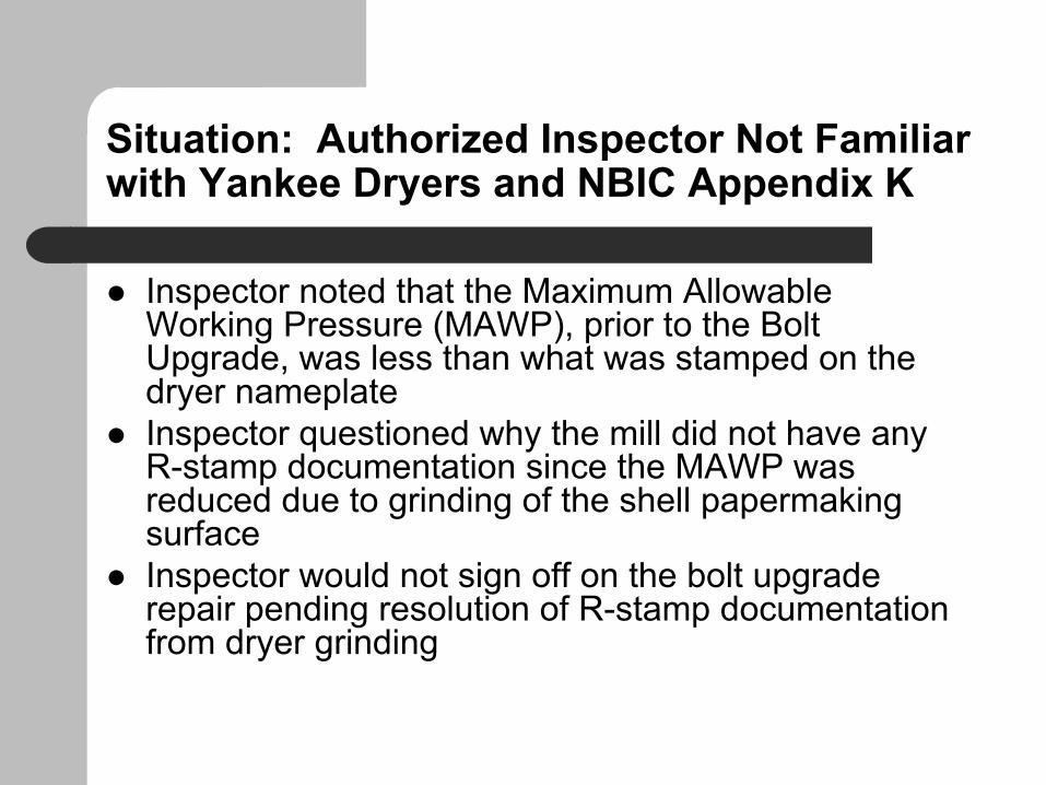
Replica Test Result
Micrograph of Crack D5-L
Crack
Type D Graphite Flakes (interdendritic segregation, random orientation)

Replica Test at Location A
Replica test Location “A “
Note: Surface condition on the journal flange surface appeared to be visually different. A replica test was performed to determine any differences in the microstructure.
Crack D5-L
Boundary showing differences in texture on journal flange surface

Replica Test Results
Micrographs at location “A” showed a variation in the microstructure on the journal flange surface
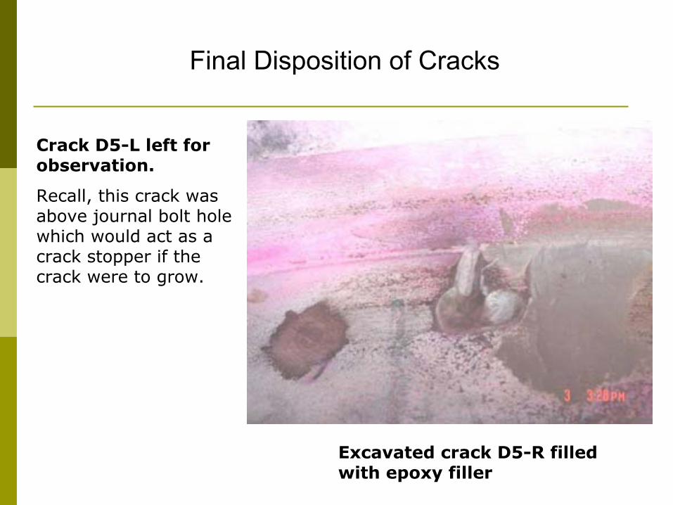
Final Disposition of Cracks
Excavated crack D5-R filled with epoxy filler
Crack D5-L left for observation.
Recall, this crack was above journal bolt hole which would act as a crack stopper if the crack were to grow.
Yankee Bolt CrackingCauses & Corrective Actions
TAPPI Yankee Dryer Safety SubcommitteeAtlanta, Georgia
4 May 2004
Brian Tholke – Procter & Gamble Co.

Yankee Bolt Cracking
How we discovered the problem
How we inspected our equipment
What we learned about the causes
What corrective actions we took
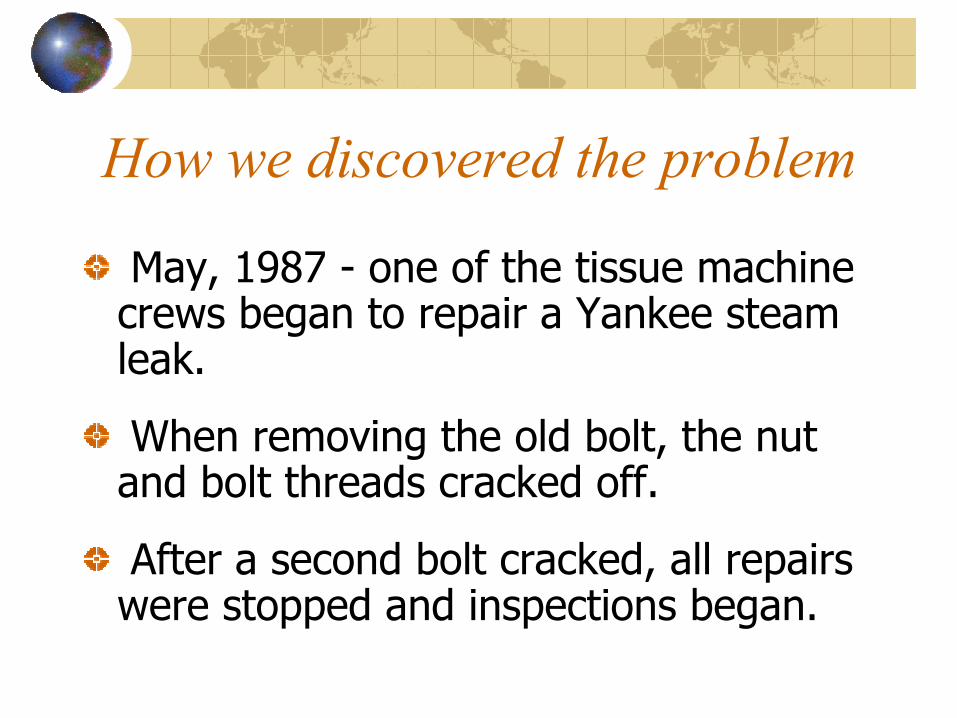
How we discovered the problem
May, 1987 - one of the tissue machine crews began to repair a Yankee steam leak.
When removing the old bolt, the nut and bolt threads cracked off.
After a second bolt cracked, all repairs were stopped and inspections began.

How we discovered the problem

How we inspected our equipment
Ultrasonic inspection testing (UT) was performed on approx. 15000 bolts
Over 600 cracked bolts were found

How we inspected our equipment
Key elements to a UT procedureEquipmentProcedureInspection standardInspector (qualified)

How we inspected our equipment

How we inspected our equipment

How we inspected our equipment

What we learned about the causesCause was “stress corrosion cracking”
Related bolt cracking factorsAlloyHardnessDesign

What we learned about the causes

What we learned about the causes
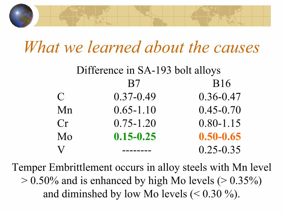
What we learned about the causesDifference in SA-193 bolt alloys
B7 B16C 0.37-0.49 0.36-0.47Mn 0.65-1.10 0.45-0.70Cr 0.75-1.20 0.80-1.15Mo 0.15-0.25 0.50-0.65V -------- 0.25-0.35
Temper Embrittlement occurs in alloy steels with Mn level > 0.50% and is enhanced by high Mo levels (> 0.35%)
and diminshed by low Mo levels (< 0.30 %).

What we learned about the causes

What we learned about the causes

What we learned about the causes

What corrective actions we took

What corrective actions we tookRequire a periodic bolt UT inspection
Replace failed SA-193 B16 material withSA-193 B7 material
Recommend max. hardness of 275 BHN
Consider use of SA-193 B7M
Replace Body-Fit with Standard bolts

Questions ?
Thank You