Embed Size (px)
Citation preview

TECHNICAL AUDIT OF VERMONT YANKEE STEAM DRYER ANALYSISIN SUPPORT OF EXTENDED POWER UPRATE REQUEST
Docket No.
License No.
Licensee:
Facility:
Audit Location:
Dates:
Participants:
50-271
DPR-28
Entergy Nuclear Vermont Yankee, LLC.
Vermont Yankee Nuclear Power Station
General Electric Nuclear Energy in San Jose, CA
August 24-26, 2004
Thomas G. Scarbrough, NRC/NRR/DE/EMEEB
Cheng-lh (John) Wu, NRC/NRR/DE/EMEB
Shah N.M. Malik, NRC/RES/DET/MEB
Dr. Vikram N. Shah, Argonne National Laboratory (ANL)
Dr. Thomas M. Mulcahy, ANL consultant
Dr. Shoei-Sheng Chen, ANL consultant
Eugene Imbro, NRC/NRR/DE/EMEB (August 25-26)

I. BACKGROUND
On August 24 through 26, 2004, the NRC staff conducted a technical audit of the analysissubmitted by Entergy Nuclear Northeast (licensee) of the steam dryer at the Vermont Yankeenuclear power plant in support of its request to operate the plant at extended power uprate(EPU) conditions. Staff members from the NRC Office of Nuclear Reactor Regulation andOffice of Nuclear Regulatory Research, and staff contractors from the Argonne NationalLaboratory (ANL) conducted the audit of the licensee's methodology and supportingcalculations for the steam dryer analysis at the GE Nuclear Energy office in San Jose, CA. TheNRC staff members and contract personnel participating in the audit (collectively referred to asthe staff in this report) are listed in Appendix A to this report.
II. AUDIT OBJECTIVE
The objective of the audit was to obtain sufficient information to enable the NRC to reach adecision regarding the adequacy of the current analysis of the Vermont Yankee steam dryer insupport of the licensee's EPU request by (1) understanding the details of the steam dryeranalysis and its supporting calculations; (2) obtaining responses to specific staff questionsrelated to the steam dryer analysis; and (3) learning about any further support for the capabilityof the steam dryer that might be provided by the licensee in the near future. The audit providedan opportunity for the staff to obtain sufficient information to reach a decision on the adequacyof the current analysis of the Vermont Yankee steam dryer in support of the licensee's EPUrequest.
Ill. PERFORMANCE OF AUDIT
At the entrance meeting, the staff discussed the objective of the audit and its plans forconducting the audit. The staff emphasized that the audit would be used to gather informationon the Vermont Yankee steam dryer analysis, and that a decision regarding the adequacy ofthe Vermont Yankee steam dryer analysis would not be made during the audit. The staffindicated that the NRC would make a decision regarding the Vermont Yankee steam dryeranalysis following review of the audit results and discussions with NRC staff and management.A list of individuals from Entergy Nuclear Northeast, GE Nuclear Energy, and other industryorganizations contacted as part of this audit (collectively referred to as the licensee in thisreport) is provided in Appendix B to this report.
At the outset of the technical discussions, the licensee presented an overview of the evolutionof the analysis of the steam dryer at Vermont Yankee. The licensee described the EquivalentStatic Method and Dynamic Response Spectrum Method used in analyzing theVermont Yankee steam dryer. The licensee also described the recent modifications to theVermont Yankee steam dryer that significantly improve its structural capability. Appendix C tothis report includes the overview slides presented by the licensee.
Following the overview, the staff specified the principal areas of concern with theVermont Yankee steam dryer analysis based on review of the licensee's submittals anddiscussions during public meetings on July 21 and 22, 2004. For example, the licenseeincluded a scaling factor of 0.03446 (1/29) in the Vermont Yankee steam dryer analysis toreduce the predicted stress to the fatigue failure criterion. Further, the correlation between datacollected at three other nuclear power plants and the load on the steam dryer at
1

Vermont Yankee under EPU conditions was not clear. In addition, the basis for using scalemodel test data to correlate data collected at different in-plant measurement locations was notapparent.
During the audit, the staff discussed the information provided in the licensee's response datedJuly 2, 2004, to the staff's request for additional information (RAI) dated May 28, 2004. Asupplemental handout provided by the licensee during these discussions is included inAppendix D to this report. The staff reviewed the basis for the Vermont Yankee steam dryeranalysis presented in proprietary GE documents. A list of the documents reviewed during theaudit is provided in Appendix E to this report. The staff also observed the performance of theANSYS computer model in identifying the mode shapes for the Vermont Yankee steam dryer.
As part of the audit, the staff visited the small scale test facility used to model steam dryerperformance at the GE Nuclear Energy office. The staff studied the steam dryer model anddiscussed the mock-up with test personnel. The staff also discussed the computer analysis ofthe collected data with the test personnel. The staff observed a test run of the facility that wasset-up to model the steam dryer at the Quad Cities Unit 1 nuclear power plant and its steamlines.
In its discussions, the licensee acknowledged the uncertainties in its analysis of theVermont Yankee steam dryer for EPU conditions. While the licensee considers the currentanalysis sufficient in light of the modifications to strengthen the Vermont Yankee steam dryer,the licensee presented the status of its ongoing development of a new acoustic circuit analysisof the Vermont Yankee steam dryer, preparation of a new computational fluid dynamics (CFD)model of its modified steam dryer, and collection of plant data to focus its analysis of theVermont Yankee steam dryer. The slides from the licensee's presentation of ongoing steamdryer analysis activities are provided in Appendix F to this report. The licensee plans to presentsome of the results of its additional analysis of the steam dryer at Vermort Yankee to the NRCstaff in late September 2004. [During the audit, industry personnel from Exelon GenerationCompany provided the staff with a brief summary of the ongoing activities at Quad Cities andDresden to resolve the steam dryer issues at those nuclear power plants.]
At the conclusion of the audit, the staff noted several follow-up items where the licensee wasunable to provide specific information during the audit. The audit follow-up items are listed inAppendix G to this report. The licensee agreed to provide information to address the auditfollow-up items as soon as possible. The additional information is not expected to significantlyaffect the results of the audit as described in this report. A supplement to this report will beprepared following receipt of the additional information, if necessary.
IV. EVALUATION
A. Overview
The steam dryer at Vermont Yankee is designed to remove moisture from the steam producedin the reactor core before the steam is directed through piping to the turbine generator. At theoutset of the audit, the NRC staff and licensee personnel discussed the intent of the licensee'sanalysis of the steam dryer at Vermont Yankee. As indicated in those discussions, the licenseeassumes that the Vermont Yankee steam dryer will maintain its structural integrity under EPUconditions. The licensee did not assert that it is acceptable for the Vermont Yankee steam
2

dryer to fail to maintain its structural integrity, and cause loose parts in the reactor coolant,steam, or feedwater systems, or result in a significant increase in moisture carryover in thesteam directed to the turbine generator. Therefore, the staff's evaluation of the VermontYankee steam dryer analysis during the audit focused on the capability of the steam dryer tomaintain its structural integrity under EPU conditions.
B. Steam Dryer Analysis Methodology
In support of its EPU request, the licensee modified the steam dryer at Vermont Yankee toimprove its structural capability based on an analysis referred to as the Equivalent StaticMethod performed by GE Nuclear Energy. In the steam dryer modifications, the licensee alsoincorporated lessons learned from the evaluation of cracks found in the steam dryer atQuad Cities Unit 2 during its refueling outage in the spring of 2004. The licensee evaluated thecapability of the Vermont Yankee steam dryer to maintain its structural capability under EPUconditions using a more recent analysis referred to as the Dynamic Response SpectrumMethod. The staff discussed the Equivalent Static Method with the licensee during the audit toobtain an understanding of the evolution of the analyses used in assessing theVermont Yankee steam dryer. However, the staff focused its evaluation of the adequacy of theVermont Yankee steam dryer analysis on the Dynamic Response Spectrum Method.
In analyzing the capability of the Vermont Yankee steam dryer using the Dynamic ResponseSpectrum Method, GE Nuclear Energy obtained pressure data from instruments installed inthree BWR plants (one in the United States and two in other countries) and used that data todevelop loading to be applied to the Vermont Yankee steam dryer. The Dynamic ResponseSpectrum Method can be summarized in a simplified manner as follows:
1. a pressure time history is obtained from each instrument installed in three referenceplants operating at different power levels;
2. each pressure time history is transformed to a pressure spectrum of pressure versusfrequency at the dryer with the use of location multipliers determined from scale modeltesting;
3. each pressure spectrum is then extrapolated to EPU conditions based on the ratio of theaverage steam line velocities at Vermont Yankee to the specific instrumented plant;
4. each pressure spectrum on the dryer is used to generate a synthetic pressure timehistory with the new amplitude but with the original phases;
5. each synthetic pressure time history is used to generate an acceleration responsespectrum with its peaks then broadened to account for uncertainties;
6. a single response spectrum enveloping the response spectra developed above isprepared;
7. the enveloping response spectrum is further broadened in an effort to include pressurepeaks in certain frequency ranges that might occur at Vermont Yankee;
3

8. using the ANSYS computer code, a structural evaluation of the steam dryer isperformed based on the enveloping response spectrum;
9. peak stress for each steam dryer component is multiplied by stress concentrationfactors to account for undersized welds and weld quality factors; and
10. the highest stress predicted at the outer cover plate weld is scaled down to meet thefatigue failure criterion of 27,200 pounds per square inch (psi), with the stress at othersteam dryer locations scaled down using the same factor.
The licensee considers the modifications to the Vermont Yankee steam dryer together with itsanalysis of steam dryer capability using the Dynamic Response Spectrum Method to besufficient to justify the structural integrity of the steam dryer under EPU conditions.Nevertheless, the licensee plans to supplement the current analysis of record for theVermont Yankee steam dryer using an acoustic circuit analysis, an updated CFD model, andplant-specific data.
C. Specific Areas of Review
1. Background
The assessment of flow-induced vibration (FIV) for a nuclear reactor system component can befairly simple or very complex depending on the structural geometry and flow field. The steamdryer is located inside the upper portion of the reactor pressure vessel and is subject tocomplex, steam flows both internally and externally. Although there are no moving parts, thedryer is composed of many structural elements. It is expected that various FIV phenomenaexist and dynamic fluid/structure interactions can be rather complex. Since the steam dryerdoes not have a safety function, potential detrimental effects of FIV, including fatigue resultingfrom FIV, were not considered explicitly or in detail in the original design evaluation. Also, thecharacteristics of steam dryer flow have not been as well studied as other components thatpossess safety functions. During the audit, the staff evaluated specific aspects of the licensee'sanalysis of the Vermont Yankee steam dryer as discussed in the following paragraphs.
2. FIV Excitation Mechanisms
In its report prepared after the failure of the Quad Cities Unit 2 steam dryer in the summer of2003, GENE-0000-0018-3359-P (Revision 1), GE Nuclear Energy stated:
The cause of the dryer failure is postulated to be high cycle fatigue resulting from lowfrequency pressure loading on the outer hoods during normal operation. The pressureloading is thought to be amplified by the geometric configuration of the main steamlines.The cracks in the hoods and braces are most likely to have been initiated during steady-state EPU power operation. The cracks continued to grow until the transient pressure loadsfrom the stuck open relief valve and subsequent manual valve openings opened the cracksthrough-wall, leading to the increased steam moisture content. The previous cover platefailure in 2002 subjected the dryer structure on the 90° side to significant additional loading.[emphasis added]
4

The staff's review of the information submitted in support of the EPU request forVermont Yankee and further presented by the licensee during this audit' revealed that theuncertainties noted in the above paragraph have not been resolved.
Identification of the excitation mechanism and formulation of a load definition is difficult,because no direct measurements of the pressure loading on the Vermont Yankee steam dryerare available. Instead of focusing on identification of FIV excitation sources, the licensee'smajor effort involved defining the dryer loading using best engineering judgement and availableinformation. In-plant pressure time histories from three other BWR nuclear power plants frominstrumentation installed in flow regions below and above the dryer hoods were used togenerate a generic load definition for all steam dryers.
The licensee had performed prior scale-model testing in an effort to determine if the coincidentalignment of the vortex shedding frequency, acoustic load frequency, and natural frequency ofthe steam dryer was the FIV excitation mechanism responsible for the 2002 Quad Cities Unit 2steam dryer failure. In essence, the licensee postulated that vortex shedding was the excitationsource amplified by an acoustic resonance that caused forced vibration of the dryer at one of itsnatural frequencies. Also, pressure time histories were obtained in previous scale modeltesting, which could have been used to define the dryer loading. However, based ondiscussions during the audit, it was apparent that the excitation source could not be confirmedand that the direct application of the time histories was not appropriate, because the mainsteam line piping was not adequately simulated. Also, the Reynolds number is distorted by afactor of 500, and simulation of boundary layer phenomena, such as separation and flow-regime development, is not assured.
Several recently initiated activities might shed light on the FIV excitation mechanism. Forexample, scale model testing is intended to simulate the effects of the piping system on thedryer. The improved modeling might aid in the identification of the excitation source andprovide confirmation of assumptions made in determining the load definition. In addition, thelicensee is collecting data at Vermont Yankee for use in an acoustic circuit analysis of thesteam dryer. This effort is intended to confirm the generic load definition, but it may also revealinadequacies in the load definition and provide new insights into the excitation mechanism. Thelicensee is also performing CFD analysis (using the Fluent code) of the flow over the dryer toassess the creation of turbulent flow and vortex shedding from the dryer hood and resultingfluid excitations. Vortex shedding may act as a trigger, or excitation source, that is amplified byacoustic resonances in the main steam lines or dryer plenum. This analysis might provideuseful information on the flow phenomena that occur over the dryer hood as well as provide asource for validation of scale-model testing.
3. Load Definition
The definition of the load on the Vermont Yankee steam dryer is made difficult by the lack ofcomplete understanding of the FIV excitation mechanisms and direct measurement of thepressures on the steam dryer. Without direct information, the licensee used engineeringjudgement to generate a load definition for the Vermont Yankee steam dryer under EPUconditions. The licensee then applied the load definition in conducting a structural analysis ofthe dynamic response of the steam dryer to flow excitations.
5

Based on review of the information submitted by the licensee and provided during the audit, thecharacter of the resulting load definition is questionable in that it does not reflect the complexityof the fluid pressures on the steam dryer. The basic assumption in the licensee's analysisregarding the nature of the pressure loading on the steam dryer is that tVe pressure is uniformand in phase over the outer hood components facing the exit nozzles. The loading over therest of the dryer (inner hoods) is assumed to be the same, except the magnitude is one-halfthat on the faces of the outer hood. In reality, significant variations in the magnitude andphasing of the pressure distribution are expected to occur over the dryer external surfaces. Forexample, large variations in the acoustic wavelengths are possible because of the variedgeometry in the dryer plenum, and large variations in the flow velocity distribution over the faceof the hood will occur as the flow converges to exit the reactor vessel. Also, based on CFDcalculations and scale-model testing results reviewed during the audit, swirling and bi-stableflow can occur near the steam line exit nozzles. In addition, nonuniform pressures can beexpected on and near the surfaces where the flow jets from the steam dryer exits.
The ability of the load definition presented by the licensee to predict reasonable bounds onflow-induced dryer response is questionable for the following reasons:
The licensee's analysis did not adequately assess the potential contribution to failure of thesteam dryer from vibration in higher modes. The assumption of uniform, in-phase, fluctuatingpressures over the entire dryer structure favors excitation of lower vibration modes with longerwavelengths (e.g., the fundamental mode of the vertical hood plate). Nonuniform and out-of-phase fluctuating pressure loads are more likely to excite higher modes, which would generatedifferent stresses and maximum stress locations. As part of the audit, the staff reviewednatural vibration modes and natural frequencies for the Vermont Yankee steam dryer in itsunmodified and modified configurations from the licensee's ANSYS computer models. In itsunmodified configuration, the Vermont Yankee steam dryer had many modes that could havebeen excited based on the frequency content of the load definition. However, contributions dueto vibrations in the higher modes were not fully evaluated, because nonuniform loading is notmodeled in the load definition. With respect to the modified configuration, ithe contributions ofnonuniform loading to the dynamic response of the Vermont Yankee steam dryer might bemore important. In particular, the modification of the Vermont Yankee steam dryer made theportion of the hood facing the exit nozzles very robust and stiff as a result of doubling thethicknesses of the vertical face plate and cover plates of the hood, and welding three gussets tothe vertical and lower horizontal plates. The licensee's modal analysis now indicates that thelowest frequency occurs around 70 Hz with the higher modes at frequencies above 120 Hz,where the load definition again suggests significant energy content. For the hood, the spatialvariations of the mode shapes have become more complex. The maximum modalaccelerations now occur on the hood's side plates, which were not stiffened, and the antinodeson the front and sides of the dryer are often out of phase.
The lack of inclusiveness of the frequency content and the magnitude of the licensee's loaddefinition question its ability to bound dynamic dryer response. Four separate time historiesfrom in-plant transducers in three other BWR plants were used to calculate four separateacceleration response spectra at licensed power levels and EPU conditions. However, directin-plant measurements of loading were not made on the critical surfaces of the dryer (e.g.,vertical and cover plates). The in-plant measurements were made in the stagnant flow area inthe annular region between the dryer skirt and the reactor pressure vessel, at flow rates at andbelow licensed power levels. The magnitudes of the in-plant pressure spectra were scaled to
6

Vermont Yankee current licensed thermal power (CLTP) levels and EPIJ conditions, based onaverage main steam line velocity. Also, scalar location multipliers were used to define thecritical surface loading from the in-plant measurements.
The licensee has not justified the scaling of the in-plant pressure spectra based on averagemain steam line flow velocity. For example, a comparison of the CFD results forVermont Yankee and Quad Cities at original licensed power levels indicates that the averagemain steam line flow velocities are significantly larger at Quad Cities than at Vermont Yankee.However, the flow velocities over the top of the dryer hoods in both plants are similar with themagnitude of the velocities diverging as the flow approaches the exit nozzles. Therefore, thegeometric scaling factor used to size the reactor internals and the main steam lines can bedifferent.
During the audit, the licensee was unable to provide a CFD model of the modified steam dryerat Vermont Yankee. As noted in Appendix G to this report, the licensee agreed to provide anupdated CFD model of the Vermont Yankee steam dryer with Reynolds numbers specified atsignificant locations as a follow-up item to this audit.
The use of scalar location multipliers to determine the load definition presumes that thepressures at the in-plant locations and on the critical surfaces are strongly correlated, or fullycoherent in the frequency domain, for all excitation sources. Thus, the frequency of an FIVsource and its energy not prominent in the in-plant measurements will not be included in theload definition. For instance, because of the location of the in-plant transducers, frequencycontent due to vortex shedding or flow turbulence close to the steam exit nozzles will not beprominently represented in the in-plant measurements or the load definition. As noted inAppendix G to this report, the licensee agreed to provide the scale model pressure spectraused in determining the location multipliers as a follow-up item to this audit.
In addition to not using pressure time histories from the scale model tests, the licensee has notevaluated the correlation between pressure measurements at different locations. Correlationsor coherence analysis could have identified the relation between the frequency content andphasing of the critical-surface loading and the measurements at the in-plant locations. Instead,the licensee compared pressure spectra from the in-plant measurements and judged them tohave similar frequency content, with some exceptions. Where obvious frequency content wasmissing, the licensee broadened the acceleration spectra calculated using the load definition inan attempt to account for the effects of the missing excitation energy.
Even if the use of location multipliers is accepted for determination of the load definition, theirability to provide upper bounds on the pressure loads is questionable, because theirdetermination was not based on a validated scale model. The scale model pressures at thein-plant locations and on the faces of the dryer do not include all main steam line acousticeffects, because simulation of the main steam line in the scale model was incomplete. Thedistortion of the Reynolds number in the scale model distortion might also affect the multipliers,because the boundary layer flow regimes that control vortex shedding and turbulence might notbe correctly simulated at the very small scale.
During the audit, the staff learned that the licensee's structural evaluation did not includedynamic effects of acoustic loads in the stress calculation for the steam dryer at the normal andupset operating conditions as well as the faulted condition due to the main steam line break. As
7

noted as a follow-up action in Appendix G to this report, the licensee plains to assess theacoustic load under faulted conditions for Vermont Yankee EPU request, and to consider anyapplicable generic issues. Also as noted in Appendix G, the licensee plans to assess thefluctuating load for normal and upset plant conditions provided in the response to staff questionEMEB-B-1 in its submittal dated July 2, 2004.
4. Extrapolation of the Load Definition to EPU Conditions
In collecting data to establish a load definition, in-plant pressures at the three reference BWRplants were not measured on the dryer faces or in the dryer plenum. Also, the absolutepressure time histories obtained in scale-model testing were not used to benchmark thepressure extrapolations. As a result, the pressures on the faces of the steam dryerextrapolated from CLTP to EPU conditions for Vermont Yankee have not been validated.
Implicit in the extrapolation method employed by the licensee to define the loads at EPUconditions is the assumption that the flow regime does not change and no new FIV excitationsources will occur above 100% CLTP. The licensee attempted to determine the rates at whichthe magnitudes of the peaks in the spectra of the in-plant pressure measurements increasedwith average main steam line flow velocity over the range of 80% to 100/c, CLTP. These rateswere used to extrapolate pressures to EPU conditions. In light of the large variations, thelicensee determined the rates by averaging over broad frequency ranges (>50 to 100 Hz).Rates significantly higher than expected were found in the higher frequency range (above120 Hz), where most of the modified dryer natural frequencies occur. These higher rates canbe an indicator of the transition to different flow regimes or the occurrence of new FIV excitationmechanisms.
The licensee had not evaluated potential fluid-elastic instabilities based on the assumption thatdisplacements in the steam dryer structure will be small. However, fluid-elastic instabilities willbe more likely to occur at EPU conditions. The licensee's extrapolation method does notresolve this uncertainty in the predicted results.
The licensee assumes that the acoustic peaks in the measured data are stable and that no newpeaks will form and overtake the existing peaks when scaling the measured data to EPUconditions. The staff's review of the spectra revealed that most of the peak frequencies weresimilar to those used in the load definition and some were not in the definition. For example,data from one of the three reference plants above 100 Hz were not used, because the licenseedid not have confidence in the higher frequency response of the transducer. In other spectra,peaks appeared at intermediate flow rates (above 50% CLTP conditions) and higherfrequencies (above 100 Hz), but it is not apparent that all would disappear as flow rates werefurther increased.
The geometric scale factor used to size reactor internals and the main steam lines might bedifferent for reactors with different CLTP levels. It is likely that the flow velocities over the top ofthe steam dryers in the different plants at CLTP will be similar, but might be different as the flowapproaches the nozzle exits. This was revealed for Vermont Yankee and Quad Cities, but isnot discussed for other reactors. The flow velocity gradients along the vertical face of the hoodare significantly larger in the Quad Cities steam dryer. The licensee's analysis does not justifythat extrapolation of the in-plant data should be based on average main steam line velocityinstead the maximum velocity or velocities at specific dryer locations.
8

In summary, without experimental data or analytical/numerical results of fluid excitation forcesat EPU conditions, extrapolation of fluid excitation forces from other plants to Vermont Yankeemakes the prediction of stresses due to FIV speculative. For example, the licensee'sassumption that the rate of increase of fluid excitation sources does not change at the EPUconditions is not confirmed by the available data on fluid pressure. Further, the licensee'sassumption that the flow field and its effects on the dryer response to fluid excitation are in thesame flow domain as those under CLTP conditions does not address the consideration that, insome cases, dynamic fluid/structure interactions can change drastically.
5. Dynamic Response Spectrum Methodology
The licensee's Dynamic Response Spectrum Methodology considers four different pressuretime histories: three measured on the skirt and one measured on the cover plate of the steamdryers at three different BWR plants (two foreign and one domestic). In the methodology, eachof the time histories is transformed to a pressure spectrum, which is then scaled toVermont Yankee operating conditions and Vermont Yankee steam dryer locations.Subsequently, a synthetic time history is generated from the scaled pressure spectrum that hasthe new amplitudes but retains the original frequencies and phases. The scaling of thepressure spectrum is based on the Vermont Yankee main steam line velocity and the multipliersderived from scale-model testing.
Using the synthetic pressure time history and assuming [ ] for all vibration modes, thelicensee generates a response spectrum for acceleration. (The response spectrum does notcontain the phasing information that is present in the synthetic pressure time history.) Thelicensee then [ ] to account for the fewfrequencies that may be present at Vermont Yankee but were absent at the other threereference plants. The licensee follows this process for each of the four measured pressuretime histories and develops the corresponding broadened response spectra. Then, thelicensee envelops these response spectra and further broadens the enveloping spectrum.
Finally, the licensee uses the broadened, enveloped response spectrum and the ANSYScomputer program to model the Vermont Yankee steam dryer and calculate the stresses in thesteam dryer structural elements. The licensee applies the square-root-surri-of-the-square(SRSS) approach to combine the stress responses from each mode. The maximum calculatedoscillating stress for the unmodified dryer at CLTP conditions is determined to be [ ] persquare inch (ksi) at the weld on the outer hood cover plate. The licensee assumes that,because the Vermont Yankee steam dryer has not experienced any high-cycle fatigue cracking,the maximum oscillating stress should be less than 27.2 ksi. Therefore, the licensee divides themaximum stress by 27.2 ksi and obtains a scaling factor of 29. The licenses applies this samescaling factor to the calculated oscillating stresses at all locations for both the unmodified andmodified Vermont Yankee steam dryer at both CLTP and EPU conditions.
The staff considers the calculated oscillating stresses to be unrealistically high, even for amethod intended to bound the structural response of the Vermont Yankee steam dryer. Inaddition, the details of the scale model testing, scaling of the in-plant measurements, and theassumptions of modal damping are lost due to the broadening of the response spectrum.Further, the licensee broadened the response spectrum twice to account for the uncertainties inthe fluid pressure and structural model. Nevertheless, certain response frequencies might bepresent at Vermont Yankee but not revealed at the plants where data were collected. The
9

broadening of the response spectrum indirectly excited many additional vibration modes of theVermont Yankee steam dryer and resulted in the unrealistically high stresses. Also, thebroadening of the response spectrum and the use of a scaling factor of 29 are likely to maskdeficiencies in defining the pressure loading on the Vermont Yankee steam dryer. In addition,many modes of the steam dryer are closely spaced and, therefore, the use of an SRSSmethodology to account for the phasing of these mode shapes is questionable. As a result, thestaff considers the Dynamic Response Spectrum Methodology used for fatigue evaluation ofthe Vermont Yankee steam dryer to not be realistic.
6. Conservatism of the Response Calculation Methodology
The licensee's use of a scaling factor of 29 at the maximum stress location for theVermont Yankee steam dryer in its unmodified configuration subject to CLTP conditions mightbe technically justified based on the absence of high-cycle fatigue cracking at that location.However, the use of the same scaling factor for all other locations on the unmodified andmodified Vermont Yankee steam dryer under both CLTP and EPU conditions has not beenjustified. Scaling factors for locations other than the maximum stress location could be smallerin light of the absence of fatigue cracking at those locations. Therefore, the Dynamic ResponseSpectrum Methodology used for the fatigue evaluation of the Vermont Yankee steam dryermight not be conservative.
The stress results for the modified dryer subject to CLTP conditions indicate that the oscillatingstress at the outer hood cover plate location (maximum stress location in the unmodified dryer)has decreased because the thickness of the cover plate was increased from 0.25 inches to0.625 inches. However, the oscillating stresses have increased at some other locations in themodified dryer where the original plate thickness was not changed. In the modified dryer, theouter hood vertical plates and cover plates are fully or partially replaced with thicker plates, butthe thickness of the inner hood and side hood plates are not changed. It is possible that theuse of smaller scaling factors would have raised these stresses above the high-cycle fatiguefailure criteria of 13.6 ksi. Therefore, the modified dryer design might have moved thesusceptible fatigue failure location from the outer hood to the inner hood of theVermont Yankee steam dryer and possibly the side plates.
During the audit, the staff identified errors in the stresses reported in the licensee's submittaldated July 2, 2004, on the analysis of its steam dryer. The licensee will provide a correctedsubmittal as a follow-up action from this audit.
7. Inspection of Underwater Welds
The staff discussed the quality of the underwater welds performed on the modified steam dryer.For welding at a depth of less than 10 meters, the licensee reported that the welds have thesame quality (i.e., porosity) as those made in the shop. Since the underwater welding for themodified Vermont Yankee steam dryer was performed at a depth less than 10 meters, thequality of these welds is likely to be acceptable. The staff suggested that the licensee considervolumetric inspection of a sample of the underwater welds to verify that large porosity is notpresent. Further, the use of ASME Section Xl visual inspection (VT-1) might be inadequate fordetecting intergranular stress corrosion cracking (IGSCC) or fatigue cracks in the steam dryer.The staff also suggested that the licensee consider enhanced visual inspection (EVT-1) for the
10

steam dryer similar to the BWR Owners' Group recommendation for the safety-related BWRvessel internals.
D. Findings
Based on the above evaluation, the NRC staff has reached the following principal findingsregarding the adequacy of the licensee's analysis, as currently presented, in supporting thestructural integrity of the Vermont Yankee steam dryer under EPU conditions:
1. The excitation source for flow-induced vibration effects and, thus, the actual appliedforcing function on the Vermont Yankee steam dryer has not been adequatelydetermined; thereby, leaving unanswered the question of whether the Vermont Yankeesteam dryer is susceptible to the same FIV mechanisms responsible for the recentsteam dryer failures at other BWR plants operating at EPU conditions.
2. The load definition on the Vermont Yankee steam dryer is incomplete. For example, thelicensee's analysis does not resolve the uncertainties in the load definition that attemptsto bound the complex nature of the fluid excitation forces acting on the dryer at EPUconditions. Also, the ability to construct a dynamic response spectrum to bound thedryer response is questionable because its frequency content and magnitude areextrapolated from the response using in-plant pressure measurements from otherreactors in stagnant regions of flow located significantly away from the critical dryerhood surfaces. Also, the extrapolation relies, in part, on the small-scale model testing,where the effects of significant Reynolds number distortion are unknown.
3. The Dynamic Response Spectrum Methodology used for fatigue evaluation ofunmodified and modified Vermont Yankee steam dryers has not been demonstrated tobe realistic. The maximum calculated stress (789 ksi) for the unmodified steam dryer atCLTP conditions is unrealistically high and reflects the uncertainty in simplifying thecomplex nature of loads experienced at EPU conditions.
4. The Dynamic Response Spectrum Methodology might not be conservative Forexample, the same scaling factor determined at the maximum stress location for theunmodified dryer at CLTP is used to scale (reduce) the stress at other locations for boththe modified and unmodified dryer at CLTP and EPU conditions. This approach topredict stresses at various locations has not been justified. Further, in the modifieddryer, the outer hood vertical plates and cover plates are fully or partially replaced withthicker plates, but the thickness of the inner hood and side hood plates are not changed.The analysis results show that the stresses at the outer hood locations in the modifieddryer will be reduced, but the stresses at some inner hood locations will increase. It ispossible that the use of smaller scaling factors would have raised these stresses abovethe high-cycle fatigue failure criterion of 13.6 ksi. Therefore, the modified dryer designmight have moved the susceptible fatigue failure location from the outer hood to theinner hood of the Vermont Yankee steam dryer and possibly the side plates.
5. Some of the in-plant measured pressure data from three other BWR plants used asinput to the structural analysis for the Vermont Yankee steam dryer was collected atdryer skirt locations. The pressure fluctuations at the dryer skirt are modified usinglocation multipliers based on the scale model test data in an attempt to generate data
11

that can be applied to the upper dryer components. The scale model tests did notaccount for the complete steam line geometry and Reynolds number. For example, thescale model did not account for the high pressure coolant injection (HPCI) steam line,the reactor core isolation cooling (RCIC) steam line, main steam isolation valves(MSIVs), turbine stop valves, and electrohydraulic controls (EHC), which are consideredpotential acoustic loading sources. Also, there was no attempt to show that the dryerskirt and hood pressures were correlated. Therefore, the validity of the scale model testdata in establishing the location multipliers has not been justified.
6. The pressure on the faces of the dryer extrapolated from CLTP to EPU has not beenvalidated. No information on pressures above CLTP is available. To define the loads atEPU, the assumption is made that the flow regime does not change and that no new FIVexcitation sources will occur above 100% CLTP.
7. The formulation used to define the Vermont Yankee plant-specific load is assumed to bedependent on the average steam line velocity. However, the fornmulation has not beenbenchmarked against test data.
8. The Vermont Yankee steam dryer analysis used the SRSS method to combinestructural responses determined for various modes of each dryer component. However,the SRSS method used to calculate resultant stresses might be non-conservativebecause the dryer model contains many closely-spaced modes.
9. The licensee's structural evaluation did not include dynamic effects of acoustic loads inthe stress calculation for the steam dryer at the normal and upset operating conditionsas well as the faulted condition due to the main steam line break.
10. The inspection plan for the modified steam dryer does not include inspections to verifythe quality of the underwater welds, which could contain large porosity. Further, the useof ASME Code, Section Xl visual inspection method (VT-1) might be inadequate fordetecting any IGSCC or fatigue cracks in the steam dryer.
V. CONCLUSION
Based on review of the information provided by the licensee in its submittals, during publicmeetings, and as part of the audit at GE Nuclear Energy, the NRC staff concludes that thelicensee's analysis of record does not demonstrate that the steam dryer at the Vermont Yankeenuclear power plant will remain capable of maintaining its structural integrity under EPUconditions. For example, the licensee's analysis of the Vermont Yankee steam dryer ascurrently submitted in support of its EPU request (1) has not adequately identified and verifiedthe excitation sources for flow-induced vibration mechanisms that resulted in significantdegradation of similar steam dryers at other BWR nuclear power plants operating at EPUconditions; (2) has not provided a complete load definition for the Vermont Yankee steam dryerfor EPU conditions in light of several assumptions that have not been adequately justified;(3) has not justified the applied methodology as realistic in light of assumptions to account foruncertainties that resulted in apparent significant overestimation of predicted steam dryerstresses; (4) might be non-conservative based on assumptions for reducing the stressexperienced by steam dryer parts and the creation of new potential fatigue failure locations as aresult of modifications to the Vermont Yankee steam dryer; and (5) has not validated the
12

extrapolation of pressure peaks from original power levels to EPU conditions for the steamdryer at Vermont Yankee. The licensee may submit a revised analysis of the steam dryer insupport of its request to operate Vermont Yankee at EPU conditions.
13

APPENDIX A
AUDIT PARTICIPANTS
Thomas G. Scarbrough, Audit LeadSenior Mechanical EngineerNRC/NRR/DE/EMEB
Cheng-Ih (John) WuMechanical EngineerNRC/NRR/DE/EMEB
Shah N.M. MalikSenior Materials EngineerNRC/RES/DET/MEB
Dr. Vikram N. ShahMechanical EngineerArgonne National Laboratory (ANL)
Dr. Thomas M. MulcahySenior Mechanical EngineerANL consultant
Dr. Shoei-Sheng ChenSenior Mechanical EngineerANL consultant
Eugene ImbroBranch ChiefNRC/NRRIDE/EMEB(August 25-26)

APPENDIX B
INDUSTRY PERSONNEL
NAME TITLE ORGANIZATION
Jim Callaghan Design Engineering Manager Entergy - Vermont Yankee
Tom Cizauskas EPU Engineer Entergy - Vermont Yankee
John Dreyfuss Director, Engineering Entergy - Vermont Yankee
Scott Goodwin Engineering Supervisor Entergy - Vermont Yankee
Brian Hobbs EPU Supervisor Entergy - Vermont Yankee
Donald Johnson EPU Engineer Entergy - Vermont Yankee
Craig J. Nichols EPU Project Manager Entergy - Vermont Yankee
Pedro Perez Senior Engineer Entergy - Vermont Yankee
Michael J. Dick VY EPU Project Manager GE Nuclear
Tom Green BWROG Project Manager GE Nuclear
Henry Hwang Principal Engineer GE Nuclear
Jim Klapproth Manager, Engineering and GE NuclearTechnology
Dave Lunger NSM GE Nuclear
Har Mehta Engineering Fellow GE Nuclear
Dan Pappone Engineering Fellow GE Nuclear
George Paptzun AES Delivery Manager and GE NuclearProcess Leader
Alex Pinkser Principal Engineer GE Nuclear
Elijio Prado Mechanical Engineer GE Nuclear
Louis Quintana Manager, Licensing GE Nuclear
Dave Sandusky Materials Application Fellow GE Nuclear
Dan Sommerville Engineer GE Nuclear
George Stramback Manager, Regulatory Services GE Nuclear
P.T. Tran Project Manager GE Nuclear
Richard Wu Principal Engineer GE Nuclear
Guy DeBoo Senior Staff Engineer Exelon Nuclear
Marcos Herrera Senior Consultant Structural Integrity Associates

APPENDIX C
STEAM DRYER FLOW INDUCED VIBRATION STRUCTURAL ANALYSIS TECHNIQUES
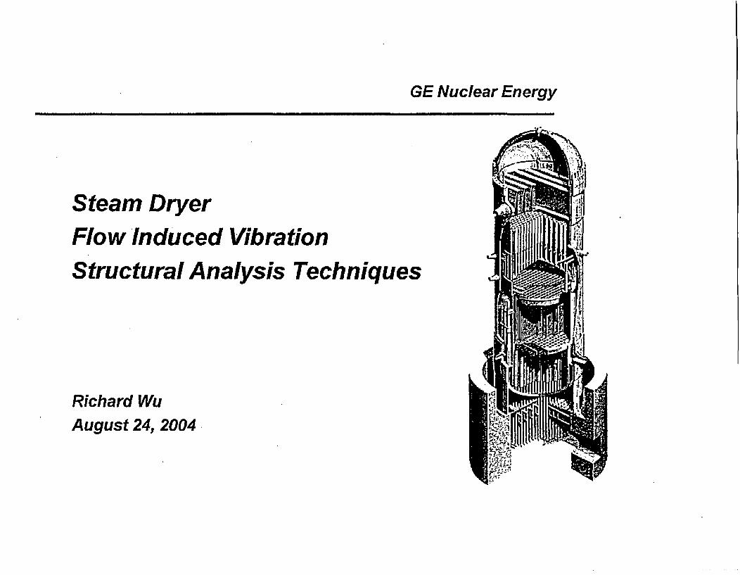
GE Nuclear Energy
Steam DryerFlow Induced VibrationStructural Analysis Techniques
Richard WuAugust 24, 2004

'1- ]]
"Equivalent Static Method of Structural Analysis"
(November 2003)
08/24/04 2

[[
131]]
"Response Spectrum Method of Structural Analysis"
(February 2004)08/24/04 3

Steam Dryer Structural Dynamic Analysis Procedure
Fluid Load DefintlionDesign Pressure
Spectrum
Pre-processorANSYS
Dryer FEM ModelGeneration
Select Analysis Method
Ir.1. Equivalent Static Method ]
Dynamic LoadPressure Time History
orResponse Spectrum
Proeshlhlr_..... r .oD.
2. Response Spectrum MethodANSYSStructural Dynamics
Response Calculation I.4-
3. Time History Method/ModalSuperpositon I
4. Time History Method/DirectIntegration I
Post-ProcessorANSYS
Stress Evaluation
08/24/04 4

t:I]]
08/24/04 5

Equivalent Static Method
1. Start with the FEA model of the Original Dryer.
2. Compute dryer component (a) natural frequenciesfrom a reference I-psi (unit) static pressure loading.
and (b) stresses
3. The Dynamic Stresses (DS) on the steam dryer components arecomputed as:
DS = (Pm+Pb) x (FIV Load rms) x (P) x (SF) x (C) x (Q)
where:
DS = Intensified Dynamic Stress (psi)
Pm+Pb = Surface stress (unintensified).
FIV Load rms = pre-EPU Pressure load as a function of componentfrequency (root-mean-squared, rms, magnitude).
P = Conversion factor from rms magnitude to Peak magnitude of thefluctuating pressure load.
08/24/04 6

Equivalent Static Method (continued)
C = Weld Stress Concentration Factor.
Q = Weld Quality Factor
SF = Scaling Factor (to account for the dynamics amplification and theload scaling)
SF =(Pm + Pb)(FIVLoadrms )(P)(C)(Q)
(No component of the Original dryer has failed at pre-EPU condition)
4. Repeat Step I to 3 with the Modified Diyer and EPU condition usingthe same SF as computed from Step 3.
08/24/04 7

Scaling Factor
(Equivalent Static Method)PeakStress
AL
FailureThreshold[E
Original DryerS F
W.A
SFOriginal Dryer *....
.0.0 A'. 00 S
or
SFModified Dryet
I Ip
Pre-EPU EPU
08/24/04 8

Dryer Structural Dynamic Response Calculation
Time History Method
Design Pressure Spectrum Synthetic Pressure Time History
P Inverse FFT
,4 :I. . .. I
V.,
Response Time History
FreqIahis"sLU *
TimeIntegration
I-
R .Ai| g ^ 0 j ~ t|~t8 ||j
9

Dryer Structural Dynamic Response Calculation
Response Spectrum Method
Design Pressure Spectrum Synthetic Pressure Time HistoryA I.4 1,.;
,,4
Is
PInverse FFT_
.. , I
W. s.w .
A'
FreqInput
F1 F2 F, (Freq) Response Spectrum
Max Response for each F* Disp
(Acc)
Fi F2 Fi
Freq08/24/04 1 0

Dryer Structural Dynamic Response Calculation
Response Spectrum Method (Concluded)K'141i"OrAlJ .
Response Spectrum
Acc(Disp) Input .
F. F2 F3
Freq
Fi,F2.F3,F4 ---- FnMaximum Response for EachDryer Vibration Mode:Stress)mode I
Stress)mode 2
SRSS orABS
I I1
Stress)mode n
08/24/04 11

SPECA05V (GENE Level 2 Code)Acceleration Response Spectrum Generation
Single Degree of Freedom System
Seismic Excitation
xf) 4 c2x4*K =-m11K(2<)X4 R ^XG X = - WX, f +Je
X'2V et) r Cd- -X (J)
X ~ (roLzc Yo7ivojr 7 or7
Forcing Excitation
Ov c x Ir-CX Fct=/Il(tlX- + 14 X ^kX~,Xprt
'A X* Afi i
)M - Do1t,- S
? (7) - /rwor.Lo A,?.Rfwt0. .Ig --TAe /
*1 - o7/eitr
tfPrt) - lpf
I x f- .
V
C-/ . .
t (IziCat08/24/04 12

Single Sine Wave Pressure Input
( 1 psi 0-peak, .25Hz)
P R E S S U R E S P E C T R U ?A
ir 1. rv t oI _ _ _ _ ___ _ _ _ _ _ ._ _._ __... ... ...
e0.
02S SO 7S 1 OD
F re q u e n c y z
T Im e H Is to ry
0.EL
: S
.
. 0.1.
IA
1.5
1 .0
o .5
0.0
-0 .5
. 1. 0
- 1.5
I _ 1
0.0 0.1 0.2 0.3 0.4 0.S 0.6 0.7 0.8 0.0 I.0 I.1 1.2 1.3 1 .4 1.S 1.6 1.7 l.8 1.9 2.0
T im e (s e c )
_- --- , .... .. ... .......-.... ... .._.. -..... ..-..-.-..... _ __. _ _
R E S P N S E 5 P E C T R U M---- ----- -" - - , -- -- -- A c C c E L E- "R ^ -AT-lo 0 , 1 N- . SI - D,- -A- -M_" , -1 N 'G'--"-"- -- "" ,,
6 0
50
_ 40
.2 3 0
f 20
U 10
___ ___ ii,-.0 5 I 0 1 5 20 25 30 35 40 45 50 55 0 6s5 70 7 5 8 a S5 90 95 1 00
F re q u e n c y (H z )1Q0 P9% 5.-. -.
V0.l I 13UV4

Three Sine Waves Pressure Int
(1 psi 0-peak, 25Hz, 55Hz,, 85Hz)
PRE SSUR E SP ECTRU M
0~.0
2 . ..-- I a 0__
F req u e ncy (H z
T im a H Is to ry
2 .0
.1.0
. 2 1 .5 - - - -- - - - - . - - - .- - - - - - .. - . - - - - - - - . -
0.A.z. 02 04 00 . . . 00 10I1 . . . 15 05 17 . . .
Tim (ea
;z2I
-iIL0uI
08/2 ,,,
R E SPO0N SE S P EC TRU M
ACC ELER AT ION .1% DAM PING
a80
5 0
40
30
20
t0
0 I1
0 5 1 0 1 5 2 0 2 5 3 0 3 5 4 0 483 5 0 5 5 a00 85 7 0 78a a0 a a5 9 0 951I0 0
C , n... -. IUL 14

Three Sine Waves Pressure Input
(I psi 0-peak, 25Hz, 30Hz, 35Hz)
PRE BS UR E SP EC TR U M
Q.
0.
0 2550 7 0 0
F re q u e n c y (H z|
T Im e H Is to ry3 .0
12 520.0
-1.0
I,.i .1.5
IL2 ,-2 .5.3.0
0 .0 0 .1 0.2 0.3 0.4 0.5 0.6 0.7 0.8 0.5 I.0 1.1 1.2 1.1 1.4 1.5 1.6 1.7 1.C 1.9 2.0
T Im e (s ec c
RES PO NS E SP EC TR U MAC C E L E R AT IO N, I % 0 AM P ING
- 60u 501;'2 4 0
I 3 0
20
C t
0 5 0 15 20 25 30 35 40 45 50 55 60 65 70 75 Ba a5 90 95 100
C . . .. n a I u ..08124,Tl.r 15
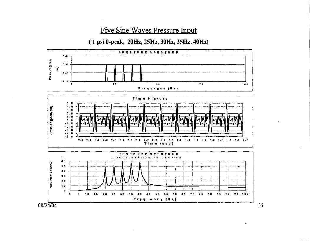
Five Sine Waves Pressure lnput
(1 psi 0-peak, 20Hz, 25Hz, 30Hz, 35Hz, 40Hz)
P R E S S U R E S P E C T R U M
'I
25 s7 . 0
Fre qu e n e y IHz)
T Im e H Isto ry
1.00 .0
a. .. 0
.5 .0 -
0.0 0.1 0.2 0.3 0.4 0.5 0 6 0.7 0.o 0. I.0 I .1 1.2 I.3 1.4 1.5 I.6 I. 1. *. t .0
T Im e (se c)
R E S P O N S E S PE C TR U MA C C E L E R A T 10 N. 1 % D A M P IN 0
401
30 I _M~~ ~~~ __ Iiq A'''l ---- - -- 4-------.20 ,,
0 5 10 1 5 20 25 30 35 40 45 50 55 60 as 70 75 80 85 90 951I0 0
F re qu e n c y (H z)
08/24/04 16

Dynamic Response CalculationResponse Spectrum Method
Multi-Dcree of Frecdom System
Forcing Excitation
i4 7( c 3 7 , J K CK7 /K J = //, /- / /4 W 12J
W.e f415f/ de' = 1 /
'4i, Al-t= /
c Cd - 3 =. *
y. j2 i
/4 AI
fl t
r. (,j' f
/A)~ P(Z-/
fq5 C,] f 9A
- Y-.SA.$1 4-..Y
t4:74e YX,. = /qfi -14 I'm
if� -
xwLS ddr7 det f~t< a
C L~ r~7P M1£4 1//- /&,_, -L)A c e-e /le 7 47;yvl CR zDdro f
X Yft . .. X,8X = rtS
08/24/04 1 7

ANSYS Input Procedure
Chapter 17 AnaI~sis Procedures
Note that the material dependent damping contribution is computed in the modalexpansion phase, so that this damping contribution must be included there.
Participation Factors and Mode CoefficIents
The participation factors for the given excitation direction are defined as:
yj = I4); [MJIDI for the base excitation option (17.7-2)
pi = (4)tl, Fi for Ihc torcc excitation option (17.7-3)
where: yt = participation factor for the ith mode
= eigenvector normalized using equation (17.3-6) (Nrmkeyonthe MODOPT command has no effect)
(D} = vector describing the excitation direction (see equation(17.7-4))
{F} = input force vector
08/24/04 1 8

ANSYS Input Procedure
Chapter J7 Analysis Procedurs
In1 = wa' AtlI (17.7-12)
( if label= DISPwhere: m = 1 if label = VELO
2 if label = ACEL
label = third field on the mode combination commands (SRSS, COC,GRP, DSUM, NRLSUM)
A; = mode coefficient (see below)
The mode coefficient Is computed in five different ways, depending on the type ofexcitation (SVTYP command).
2. For SVTYP, 1 (force excitation)
A; = -.. Yi (17.7-14)
where: S = spectral force for the ith mode (obtained from the inputamplitude multiplier table at frequency fj and effectivedamping ratio Q).
3. For SVTYP 2 (acceleration excitation of base)
A. = ai - i (17.7-15)
where: Sai spectral acceleration for the jth mode (obtained fromthe input acceleration response spectrum atfrequency f1 and effective damping ratio t;).
08/24/04 1 9

131]]
08/24/04 20
Vermont Yankee, CLTP Dryer Load I
t3.]]
08/24/04 21

08/24/04 22

Vermont Yankee, CLTP Dryer Load 2
- 3] ]
08/24/04 23

Input Response Spectrum
1. Start with a (Single) Plant Measured Pressure Time History
2. Transform to Pressure Spectrum (Frequency, Amplitude, and Phase)
3. Scale the Pressure Spectrum Amplitude According to Plant SpecificOperating Condition
4. Generate a new Pressure Time History with the new Amplitude andthe Original Phase
5. Calculate a Response Spectrum based on the new Pressure TimeHistory
6. Repeat Steps 1 through 5 with a Different Plant and/or a DifferentGage Measured Pressure Time History
7. Envelope and Broaden the Response Spectra from Step 5
8. Input to ANSYS for Steam Dryer Dynamic Response Evaluation
08/24/04 24

lo }]]
08/24/04 25

'1 l]]
08/24/04 26

'v:]]
08/24/04 27

Is II]]
08/24/04 28

08/24/04 29

'3:]]
08/24/04 30

08/24/04 31

13:]]
08/24/04 32

131]]
08/24/04 33

'3S]]
08/24/04 34

'09]
08/24/04 35

Scaling Factor(Response Spectrum Method)....
Original Dryer .. '..4.. 00
PeakStress
FailureThreshold[E ]]
SF
F
SFOriginal Dryer *oe''
000000.0G
-� I.U
SFModified Dryer
lb
I I
Pre-EPU EPU
08/24/04 36

APPENDIX D
VERMONT YANKEE PLANT-SPECIFIC ANALYSIS

GE Nuclear Energy
VY Plant Specific Analysis
By: Henry Hwang
July 21, 2004
Page 1 of2l

1.0 Dryer pressure loads
Example of dryer pressure time history is shown below:
Pfiv
Ps
The pressure time history can be divided to two parts, Ps and Pfiv,
Ps Static pressure on the dryerPfiv Fluctuation component causes Flow Induced Vibration (FIV).
Page 2 of 21

From this morning meeting,
(1) QC steam dryer cracking was caused by high cycle fatigue.
(2) The fractures initiated at the weld toes.
(3) No dryer failures prior to QC power uprate.VY MS LPU flow velocity is less than QC CLTP
Therefore, Pfiv is the major concern
Page 3of 21

2.0 FIV Alternating Stress by Response spectrumanalysis, peak broadened, enveloped andscaled
The purpose of this section is to explain:
Stress distribution from response spectrum analysesExample plots cover plate and front hood.
Conversion of maximum shell stress to Salt in the weldsExample Cover plate and front hood
Original dryer and modified dryer
Explain Normalized factor 29
(sec 2.1)
(sec 2.2)
(sec 2.3)
Explain the reasons: (sec 2.4)Modified dryer cover plate stress reduction 17 timesModified dryer front hood top weld stress reduction 3 times
Toe of Fillet weld stress from 2D-isoparametric solid detail model(sec 2.5)
Page 4 of 21

Stress distribution from response spectrum analysesExample plots cover plate and front hood
(2.1.1) Example stress distribution plots forVY original dryerlower cover plate, CLTP
[[
Page 5 of 21

(2.1-2) VY original dryer response spectrum analysisfront hood stress distribution, CLTP
Page 6of21

(2.1-3 ) Stress distribution plots forVY modifier dryercover plate, CLTP
[I[
IfI
11
* -Page 7 of 21

(2.1-4) VY Modified dryer response spectrum analysis, outer
hood, CLTP-
II
Page 8 of 21

(2.1-5 ) Stress distribution plots forVY modifier dryercover plate, LPU
1[
1]
Page 9 of21

(2.1-6) VY NIodified dryer response spectrum analysis, outer
hood, LPU-
[[
H
Page 10 of 21

Conversion of maximum shell stress to Salt in the weldsExample Cover plate and front hood
Original dryer and modified dryer
(2.2-1) Dryer plate thicknessesOriginal Dryer
plate Weld size Under Weld factor Totalthickness size stresss
factor factor
Original 0.25 0.187 ifdryerLowerCover plate
Original 0.5 0.5 IIdryer, fronthood
Modifier Dryer
Plate Weld size at Under Weld TotalThickness top plate size factor stresss
factor factor
Modified 0.625 0.625dryer, lowercover plate,tip
Modified 1.0 0.625dryer, fronthood topweld
Page 11 of 21

(2.2-2) Salt Stress calculation
11
Original dryer, CLTP (Current Licensed Thermal Power)
Max CLTPSurface PeakStress Weld under size Stress(psi) Factor plate thick weld size factor (16) (1)x(5)x(6)(1) (LO (6) (9)
Outer cover plate1/4", 3116" weld JL.0.250 0.188 .Outer front hood 11 _ _0.50 0.500
Modified dryer, CLTP and LPU (Licensed Power Uprate)
CLTP LPUMax Max under CLTP
Surface Surface size Peak RepairedStress Stress Weld plate weld factor Stress LPU(psi) (psi) Factor thick size 1 (1) x(S)x(6) Peak(1) (2) (5) (6) (9) (10)
Outercover platetips _ _0.625 0.625 [[Outerhood, topweld ._ _1.00 0.625 11
Page 12 of 21

(2.3) Explain Normalized factor [[ ]]
Because the dryer has not failed at the maximum stress location foryears of operation, the peak stress value is normalized to the fatiguefailure criterion [[ ]] for CLTP.
Stress limit ASME Appendix I, Figure 1.9.2.2 Curve CAllowable number of cycle = 1011
Salt = 13,600 psi,The maximum effect mean stress is included in Curve C.
The normalized factor, NF is back-calculated:
[[I
Page 13 of 21
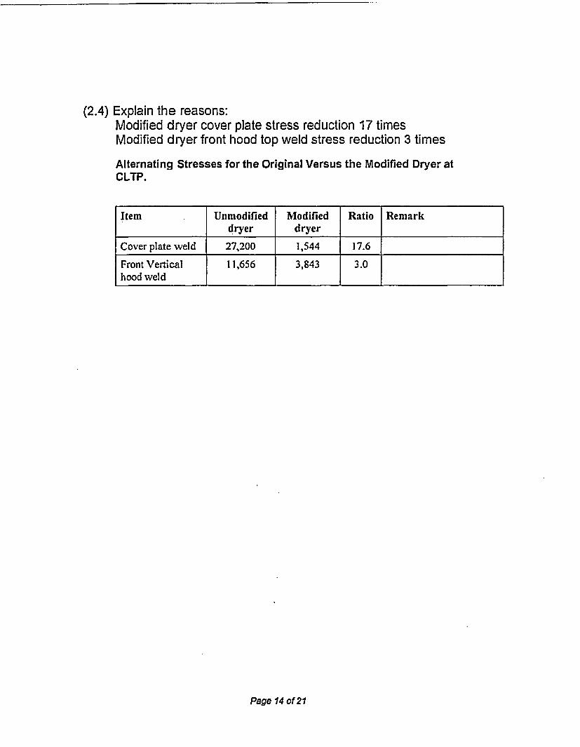
(2.4) Explain the reasons:Modified dryer cover plate stress reduction 17 timesModified dryer front hood top weld stress reduction 3 times
Alternating Stresses for the Original Versus the Modified Dryer atCLTP.
Item Unmodified Modified Ratio Remarkdryer dryer
Cover plate weld 27,200 1,544 17.6
Front Vertical 11,656 3,843 3.0hood weld
Page 14 of 21
2.5 Toe of Fillet weld stress from 2D-isoparametric solid model, planestrain
[a
Page 15 of 21

From analysis results of shell model for 1 psi static case.The average forces at 3.5" away from the fillet weld front hood surfaceare as follows.
II11
Cover plate thickness = 0.375"
The Fy acting on the fillet weld creates a moment of 1[the fillet weld
[l
Factor used in the report:
[C
Therefore, the factors are reasonable
li on
Page ;J6of2l
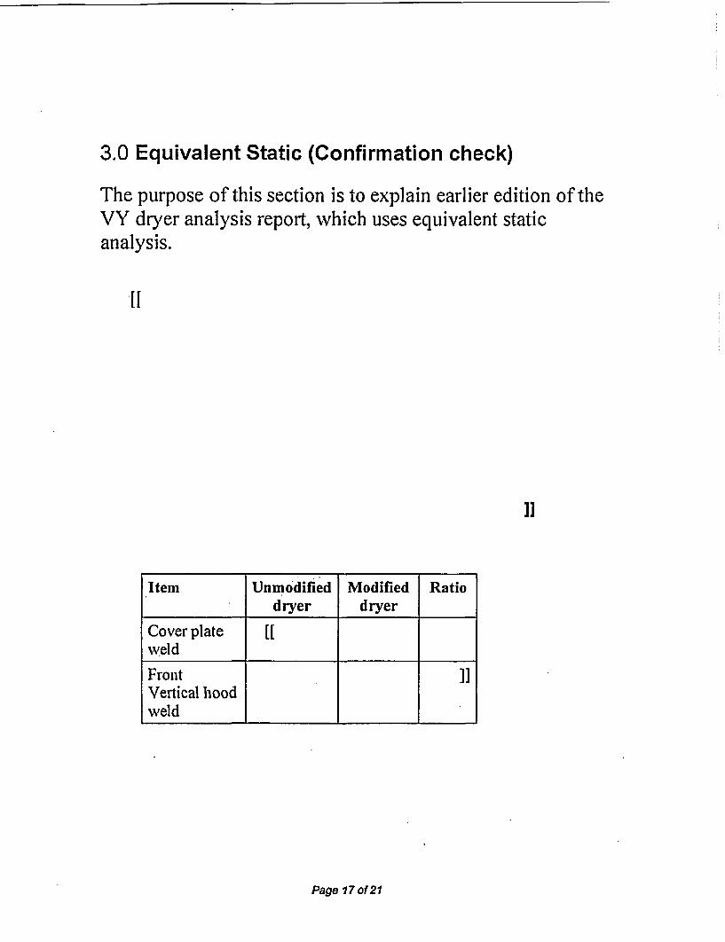
3.0 Equivalent Static (Confirmation check)
The purpose of this section is to explain earlier edition of theVY dryer analysis report, which uses equivalent staticanalysis.
*1[
1]
Item Unmodified Modified Ratiodryer dryer
Cover plate [weld
Front 1]Vertical hoodweld
Page 17of21

4.0 ASME loads and load Combinations
ASME Primary load stress limits:
Pm General membrane stressPm+Pb Primary membrane plus bending stress
Pmi Pm+PhService Levels A/B 1.0Sm =1n l.5.,=[1Service Level D 2.4Sm= [[ 3 3.6Sm = [[
ASME Code Section III Load Combinations
Service Level Load Combination
Level A normal pressure + dead weightLevel B 1 upset pressure + dead weight + OBELevel B 2 upset pressure + dead weight - OBELevel B 3 normal pressure + dead weight + TSV + OBELevel B 4 normal pressure + dead weight + TSV - OBE
Level B 5 normal pressure + dead weight + TSVflow-induced + OBELevel B 6 normal pressure + dead weight + TSVflow-induced + OBELevel D I faulted pressure + dead weight + SSELevel D 2 faulted pressure + dead weight - SSE
The most limiting stress is Service Level B
Positive and negative seismic load are combined (equivalent to absolute sum)
For Modifier dryer the maximum stress occurs at long gusset listedbelow. All other locations are listed in stress report.
Page 18 of 21

Long Gussets Welds ASME Primary and Secondary Stresses
(B) Local(A) Local Surface (C) Pm+Pb membrane (D) Pm + Pb + Q
membrane maximum Plate Fillet Undersized (A) x (C) Allowable Primary stress, AltematingService Load stress stress thickness eld size Weld stress at weld stress stress (B)x(C) stress, Salt
Item Level Case (ps!) (psi) (inch) (inch) factor (pso (psi) ratio (psi)(psi)I I psi - 0.500 2x0.375 ff2 Level A 1 0.500 2x0.3753 Level B 1 0.500 2x0.375 .4 Level B 2 0.500 2x0.3755 Level B 3 . 0.500 2x0.3756 Level B 4 0.500 2x0.3757 Level B 5 0.500 2x0.3758 Level B 6 0.500 2x0.3759 Level D 1 0.500 2x0.375
10 Level D 2 n 0.500 2x0.375 . __
Page 19 of 21
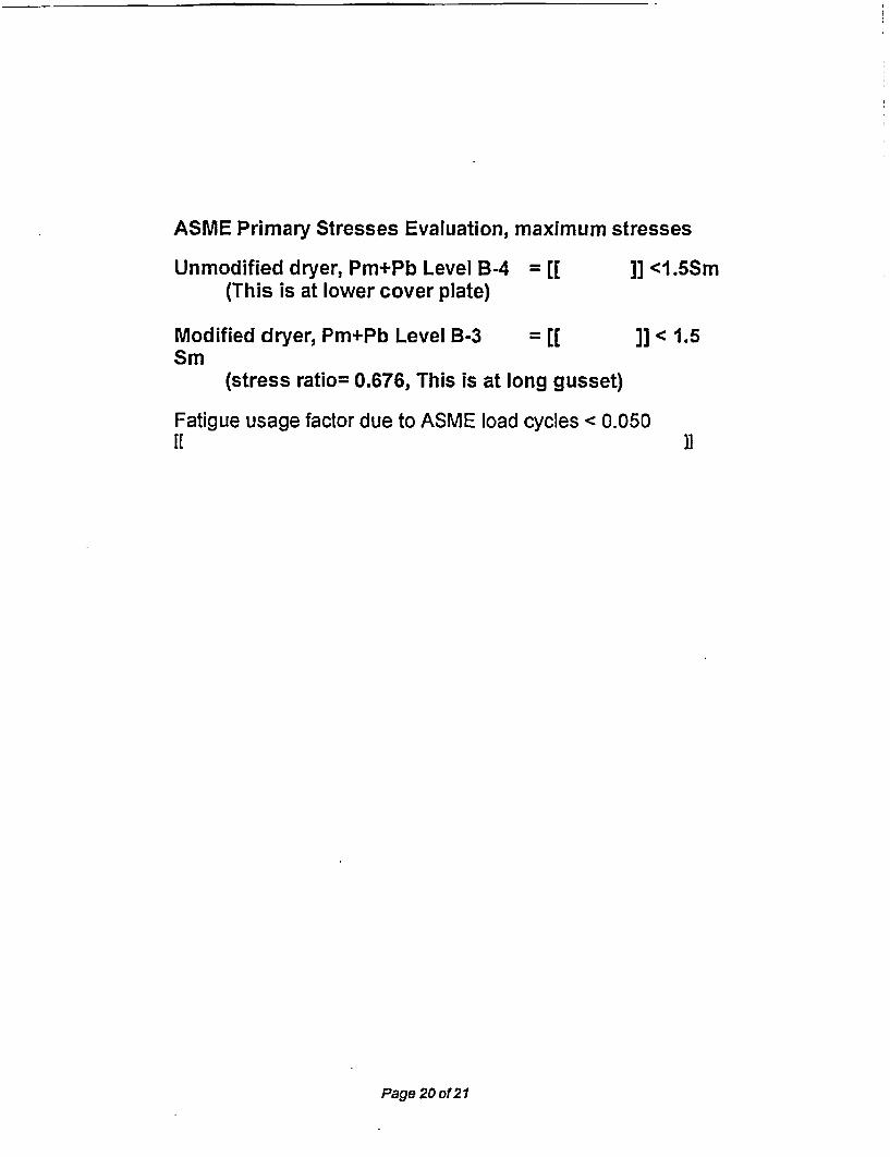
ASME Primary Stresses Evaluation, maximum stresses
Unmodified dryer, Pm+Pb Level B-4 = [l ]] <1.5Sm(This is at lower cover plate)
Modified dryer, Pm+Pb Level B-3 = [[ ]] < 1.5Sm
(stress ratio= 0.676, This is at long gusset)
Fatigue usage factor due to ASME load cycles < 0.050[[ 1]
Page 20 of 21

Page 21 of 21

APPENDIX E
DOCUMENTS REVIEWED
GE-NE-0000-0024-7944-1 (Revision 1, March 2004)uEntergy Nuclear Operations Incorporated Vermont Yankee Nuclear Power Station SteamDryer Modification"[Proprietary]
GE-NE-0000-0024-7944-2 (Revision 0, April 2004)'Entergy Nuclear Operations Incorporated Vermont Yankee Nuclear Power Station SteamDryer Modification Supplement 1"[Proprietary]
GE-NE-0000-0024-7944-3 (Revision 0, June 2004)'Entergy Nuclear Power Operations Incorporated Vermont Yankee Nuclear Power StationSteam Dryer Dynamic Response Spectrum Analysis"[Proprietary]
GE-NE-0000-001 6-9523-01 (Revision 0, July 2003)"Entergy Nuclear Operations Incorporated Vermont Yankee Nuclear Power Station ExtendedPower Uprate Task T0303: RPV Internals Structural Integrity Evaluation"[Proprietary]
GE-NE-0000-0016-4161-01 (Revision 0, January 2004)"Entergy Nuclear Operations Incorporated Vermont Yankee Nuclear Power Station ExtendedPower Uprate Task T0305: RPV Flow Induced Vibration"[Proprietary]
GE-NE-189-11-0292 (March 1992)'Steam Dryer Vibration Measurement Program Fukushima Daiichi Unit I"[Proprietary]
GE-F4100056-02 (February 1997)'Kashiwazaki-6 Steam Dryer Hammer Test Final Report"[Proprietary]
NEDC-32791P (February 1999)"Vermont Yankee Nuclear Power Station Increased Flow Analysis'[Proprietary]
NEDC-33090P Table 1-1 "Computer Codes Used for CPPU"[Proprietary]
DRF 0000-0016-1512 (April 21, 2003)Quad Cities Steam Dryer Report
DRF 0000-0019-1512 (July 28, 2003)Vermont Yankee Steam Dryer CFD Report

DRF 0000-0020-4661Section 0000-0022-4955 (August 24, 2004)"Reference Fluctuating Pressure Load Definition"[Proprietary]
DRF 0000-0028-9723Section 0000-0028-9735 (May 15, 2004)"Vermont Yankee Fluctuating Pressure Load Definition - 'Refined' Approach"[Proprietary]
PL234C6402 (Revision 1, April 2, 2004)"Steam Dryer Modification"Parts ListInstallation Specification[Proprietary]
MDE #199-0985 (October 1985)'Susquehanna-1 Steam Dryer Vibration Steady State and Transient Response"[Proprietary]
Methods of Radiographic Test and Classification of Radiographs for Stainless Steel Welds,JIS Z 3106 (Japan Industrial Standards), 1971
2

APPENDIX F
ENTERGY VERMONT YANKEE POWER UPRATE PROJECTNRR GE NUCLEAR ENERGY DRYER AUDIT PRESENTATION

Entergy
En ergPower Uprate Project
NRR GENE Dryer AuditPresentation
August 26, 2004John Dreyfuss, Craig Nichols, Brian Hobbs,
Tom Cizauskas, Don Johnson, Pedro Perez (via phone)1

AdEMIL-
EnLg
.I.
.5. VY Presentation Overview_ ,.j m., .. A-.
m Review of key NRR Audit Team issues
* VY plant-specific load definition* Confirm applicability of GE load definition by:
* Data collection* Acoustic circuit model development* ACM analysis* Results application
* VY vortex shedding evaluation* CFD model development* Results application
* Schedule for meeting with NRR on resu Its 2

-Energy
Key NRR Audit Team Issues
* Applicability of generic load definition:* Frequency & amplitude spectrum* Addressed by CDI acoustic circuit model
* Vortex shedding:* Contribution to dryer loads* Addressed by Fluent CFD model
* Identification of acoustic sources:* Branch lines, TCV's, turbine control system* Addressed by CDI acoustic circuit model
3

-- Etergy
Ax' VY Plant-Specific Load Definition
* Collection of plant-specific data
* Development of VY Acoustic CircuitModel
* Acoustic 'circuit analysis
* Application of results
* Piping vibration plant data
4

VY Plant-Specific Load Definition(cont.)
- Plant-specific data collection• VY pressure data taken at:
• MSL venturis (one on each steamline). Vessel instrument reference legs (2)• Main steam header (one on each steamline)
* VY strain gauge data taken at:MSL, vertical run close to RPV (one on eachsteamline)
* Sampling rate i 1024 samples/sec• Data taken at 80%, 85%, 90%, 92%, 95%,
96% and 100% power5

- En terg
.7, -VY Plant-Specific Load DefinitionM1F~7 -.o
77 (cont.)
High SpeedPressureSensors ~(10)

fik
-- Etegy
7 VY Plant-Specific Load Definition (cont.)
. Acoustic circuit model developedusing:E VY (modified) dryer dimensionsE Main steam system dimensions, including
branch lines
Model will be independently audited
7

-= Etergy, ; . . I
� -,;-,n ,77�.;_ .
. VY Plant-Specific Load Definition (cont.)
. Acoustic circuit dryer diagram:TOP VIEW: MS270 MSL D
2,3 -l
N-11B/
104,05 i\ Prsure data
locations.MSL B 90. MSL A
SIDE VIEW: Pressure datalocations
A /H D C B
Nominal Water Lvel
*-- ------ --G------------a ---------- e -2 104
Schematic of pressure node locations on the steam dryer at Vermont Yankee.
8

�_
A=h
1--~Entergy. r.
BY. :-V Plant-Specific Load Definitionraw.z 0. ,
X Acoustic circuit dryer diagram (cont.a):
(cont.)
R
7 1.b.a
I
_,_ b02 -a__. b2 .
III -
I_-d4-
cI . k 4
Steam-WaterP~ Interface.
e
h
1'g
F
Cross-sectional description of the steam dome and dryer at Vermont Yankee, with thevalidated dimensions of a = 6.0 in, bi = 13.75 in, b2 = 27.5 in, c = 18.0 in, dI = 7.75 in,
d2 = 15.5 in, e = 16.75 in, f = 75.5 in, g = 137.0 in, h = 35.5 in (reference legs),i = 88.5 in, j = 148.5 in, k = 100.5 in, and R = 102.5 in.
9

- Etergy
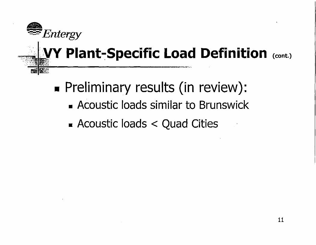
VY Plant-Specific Load Definition (cont.)
* Application of acoustic circuit results• Comparison to GE load definition
* Comparison to other plants' acoustic loads
* Extrapolation to EPU conditionsm Confirm during Power Ascension Testing
10.
I-En tergy
VI IVY Plant-Specific Load Definition (cont.)
v Preliminary results (in review):* Acoustic loads similar to Brunswick
* Acoustic loads < Quad Cities
11

--- Entergy
-4e -V MY Plant-Specific Load DefinitionIF (cont.)
EM I-l
CDI Dryer Node 10
._co,
CLa-
6.00E-03
5.OOE-03
4.OOE-03
3.00E-03
2.OOE-03
1 .OOE-03
O.OOE+000 50 100 150 200 250 300
Frequency (hz)
IPRELIMINARY UNVERIFIED-I
12

--Entiiy
.17 1. . 1I'I
; - ~1. VY Plant-Specific Load Definition (cont.)
- I C
CDI Dryer Node 983.50E-02 T
3.OOE-02 -
2.50E-02 -
2.00E-02 -
1.50E-02 -
(n
enE
EL
1.OOE-02
5.00E-03
O.OOE+00 k LI -IL I
0 50 100 150 200 250 300
Frequency (hz)
I PRELIMINARY UNVERIFIED I13

%--- ,Entergy
.. .., ..
* _v7n. VY Plant-Specific Load Definition (cont.)
-9�� -
. .
I PRELIMINARY UNVERIFIED I 14

VY Plant-Specific Load Definition (cont.)
Piping vibration plant data* Indicator of acoustic load frequency
and amplitude* Plant EPU vibration comparisons (see
chart):E Piping vibration similar to Brunswick
* Piping vibration < Quad Cities
15

��- I7 .�
t~Entegy
WVY Plant-Specific Load DefinitionEPU Maximum Measured Acceleration (cont.)
E Es.:1 .400 7-7
1.200
1.000
, 0.800
CuL.n
c}ca 0.600
0.400
0.200
0.000Dresden Unit 3 Quad Cities Unit I Quad Cities Unit 2 Brunswick Unit I
Plant
Vermont Yankee
16

- En tergy
VY Vortex Shedding Evaluation
* CFD model development
* Results application
17

- En tety
VY Vortex Shedding Evaluation (cont.)
- CFD model development:. Methodology -. Fluent• Boundaries, geometry & mesh
RPV Dome, RPV annular region, Dryerinternals and Skirt
• RANS unsteady solution provides LESboundary conditions
• LES solution capable of, modeling localvortices at cover plate
18

,.- ...... .- - n f
R -PA NS M odel Copyright 2004 Fluent Inc. All rights reserved.
*Preliminaryresults.Example*Contours of/velocity 4
magnitude
S �S -6. -. -
19

t---En tegy
-11 , - RANS Solution Copyright 2004 Fluent Inc. All rights reserved.
-'-. -t_
* Preliminaryresults
* Examplem Contours of
pressure
S S S S .I
20

w
- LES M esh Copyright 2004 fluent Inc. All rights reserved.
w-7 Uen: ° _
eybrid mesh .
eSignificant volume
decomposition for
maximum use of hex ~.
*'~2M cells
*Profile of u,vwk,efrom RANS solution __imposed at velocity
inlet
21

Vortex Shedding Evaluation (cont.). -a N - St..... -
* CFD results application:Address turbulence driven and vortexshedding load contribution
22

-~ - Eergy
Schedule for Meeting with NRR
- Complete VY-specific loaddefinition -- early September
* GE compare VY-specific and GEload definitions - mid-September
* Entergy meet with NRRSeptember
- late
23

APPENDIX G
AUDIT FOLLOW-UP ITEMS
1. Vermont Yankee CFD analysis for modified dryer with Reynolds numbers specified atsignificant locations
2. Assessment of acoustic load under faulted conditions for Vermont Yankee EPU requestand any generic issue
3. Scale model pressure spectra used in determining location multipliers
4. Correction of Table EMEB-B-1-3 in Entergy submittal dated July 2, 2004, withexplanation of changes
5. Assessment of fluctuating load for normal and upset plant conditions for RAI responseEMEB-B-1 in Entergy submittal dated July 2, 2004