Embed Size (px)
Citation preview

In SPIE vol. 3362, Helmet and Head-Mounted Displays III, AeroSense 98, Orlando, FL, April 13-14, 1998 1
Miniature 6-DOF inertial system for tracking HMDs
Eric Foxlin, Michael Harrington and Yury Altshuler
InterSense, Inc., 73 Second Ave., Burlington, MA 01803
ABSTRACTCurrent HMD applications are hampered by the limitations of head-tracking technologies now in use. Commercially availablemagnetic, optical, acoustic, and mechanical head-trackers suffer from various problems such as vulnerability to interference,line-of-sight restrictions, jitter, latency, small range, and high cost. This paper presents inertial-sensor-based hybrid trackingtechnology that was developed to combat all these problems. Two commercially available products, the IS-300 and the IS-600, are described, both based on the same miniature triaxial inertial sensor device. The IS-300 is a sourceless 3-DOForientation tracker, using gravimetric tilt-sensing to prevent any gyroscopic drift in pitch and roll, and optional geo-magneticcompassing to prevent any gyroscopic drift in yaw. The IS-600 is a hybrid acousto-inertial 6-DOF position and orientationtracking system. It tracks changes in orientation and position by integrating the outputs of its gyros and accelerometers, andcorrects drift using a room-referenced ultrasonic time-of-flight range measuring system. This paper overviews the theory ofoperation of both systems, and reports bench-testing results designed to evaluate the resolution, accuracy, and latency of eachsystem.
Keywords: head-mounted displays, tracking, inertial measurement, gyros, accelerometers, magnetometers, ultrasonic time-of-flight, virtual environment simulation
1. INTRODUCTIONOne of the main technological bottlenecks in virtual environment, augmented reality (AR), and teleoperator systems usinghead-mounted displays (HMDs) is head-tracking. Head-tracker noise causes the virtual scene to jitter, reducing presence andcausing simulator sickness. Latency causes the objects in the virtual world to swim during head movements. Range limitationsprohibit the use of VR for applications such as mobile operations training or architectural walk-throughs. Distortions of thehead-tracker output mapping cause confusion during haptic interaction with physical objects that should match virtual visualobjects, and cause visual misregistration of virtual and real objects in AR displays. Other important factors are environmentalinterference, degree of user encumbrance, convenience of operation, and cost.
In the past, there have been a variety of mechanical, ultrasonic, magnetic, optical, and gravimetric head-trackers available.1,2,3
Mechanical trackers are capable of very good accuracy, resolution, and interference immunity, but they have extremelylimited range and tend to encumber the user. Ultrasonic time-of-flight trackers can have relatively large range at low cost, butthe need to wait for echoes to die out before initiating a new measurement can cause low update rates, particularly whentracking large volumes. The most common technology today is magnetic tracking, which is convenient because it does nothave the line-of-sight problems of optical and ultrasonic systems. The biggest problems with magnetic systems are distortionscaused by metal objects, and a very rapid decrease in accuracy and resolution with distance. Optical head-trackers have beenbuilt using cameras or other position-sensitive optical devices to track IRED beacons, and using laser range measurementtechniques. Both methods tend to provide reasonable range, accuracy and resolution, but suffer from line-of-sight restrictions,reflections and very high cost. Gravimetric trackers (typically using a fluid-filled inclinometer and a compass) are usuallyprovided as a built-in component of very low-cost consumer HMDs. These systems measure orientation only, are sensitive tomagnetic interference, and suffer from a high level of “slosh”, ie. false orientation readings caused by linear accelerations.
This paper describes two commercially available motion tracking systems, the IS-300 and the IS-600, which are differentfrom previous motion trackers in that they rely on micro-machined inertial sensors for their primary measurements. Thistechnology offers several potential advantages:
• Very low latency• Prediction based on directly sensed motion derivatives• Superb resolution / negligible jitter over entire range
The orientation tracker (IS-300) and the orientation outputs of the 6-DOF tracker (IS-600) have the following benefits inaddition:

In SPIE vol. 3362, Helmet and Head-Mounted Displays III, AeroSense 98, Orlando, FL, April 13-14, 1998 2
• Unrestricted range• Immunity to all forms of interference• No line-of-sight problems• Portability: no source to set up.
In the next section we provide a theory of operation for these two systems, beginning with a brief background review ofinertial navigation systems, followed by discussion of some of the challenges of building miniature inertial systems for motiontracking on a human scale. Section 3 delves into specific discussion of the IS-300 and IS-600 systems, including hardware andfirmware configurations and operating mode selection considerations and trade-offs. Section 4 shows test results on theresolution and accuracy of the systems in two of their main modes, and the conclusion is in Section 5.
2. THEORY OF OPERATION
2.1 Inertial Navigation BackgroundThe operating principles for measuring orientation and position of a moving body using only gyroscopes and accelerometershave been well established in the field of inertial navigation systems (INS) 4,5,6. The original navigation systems were builtwith a gimballed platform that was stabilized to a particular navigation reference frame by using gyros on the platform todrive the gimbal motors in a feedback loop. The platform-mounted accelerometers could then be individually doubleintegrated to obtain position updating in each direction. Most recent systems are of a different type, called strapdown INS,which eliminates the mechanical gimbals, and measures the orientation of a craft by integrating the angular rates from threeorthogonal angular rate sensing gyroscopes (hereafter “gyros” or “rate gyros” or “angular rate sensors”) strapped down to theframe of the craft. To get position, 3 linear accelerometers, also affixed to orthogonal axes of the moving body, measure thetotal acceleration vector of the body relative to inertial space. This acceleration vector can be converted from bodycoordinates to earth coordinates using the known instantaneous orientation of the body determined by the gyros. Position isthen obtained by subtracting off the effect of gravity from the measured acceleration and then performing double integrationstarting from a known initial position. Figure 1 illustrates this flow of information.
rate gyros orientationintegration
accelerometerstransform tolocally-levelnavigation frame
subtract gfrom verticalacceleration
integrate to getvelocity
integrate toget position
initial v initial r
outputposition
ωΒ
aB aN
CBN
vN rN
Figure 1: Basic strapdown inertial navigation
Drift in the determination of orientation results mostly from gyro biases, defined as the output produced by a gyro at rest.Fixed biases, if uncompensated, lead to a constant rate of drift after integration. However, the startup biases can usually bemeasured before take-off and corrected. What matters, then, is bias stability. The typical drift performance of a ring lasergyro (RLG) is about 0.001°/hr, which is sufficient for an INS whose position indication needs to be accurate within about amile for one hour. Smaller and less costly are fiber optic gyros (FOGs) and dynamically tuned gyros (DTGs), which canachieve drift rates in the .01-1°/hr range, sufficient for short-duration tactical missile flights. Recently, very low cost Coriolisvibratory gyroscopes (CVGs), including micro-machined versions, have been developed for the automotive and remotelypiloted vehicle markets. These have drift rates ranging from several degrees per hour to a degree per second.
Drift in the linear position determined by an INS arises from several sources. First, there are accelerometer instrument errors,such as bias stability, scale factor stability, nonlinearity and misalignment. Inertial grade accelerometers, such as those in the1 mile/hr INS mentioned above, must keep all these errors to a few µg. Considering the 50g maximum accelerations that theseaccelerometers must contend with, this represents a 106 dynamic range! Tactical grade inertial systems can get by with 100µg-class accelerometers. Since position is obtained by double integrating acceleration, a fixed accelerometer bias error ab
results in a position drift error, x a tb= 12
2 , which grows quadratically in time. It is therefore especially critical to accurately
estimate and eliminate any persistent bias errors. A second critical cause of error in position measurement is error in the
In SPIE vol. 3362, Helmet and Head-Mounted Displays III, AeroSense 98, Orlando, FL, April 13-14, 1998 3
orientation determined by the gyros. Since the INS interprets the direction of the measured acceleration according to thecomputed orientation of the platform, any error in this computed orientation will cause it to integrate the accelerometers in thewrong direction, thus deviating slightly from the true course of the vehicle. More importantly, the cancellation of gravity willbe performed imperfectly by the navigation computer, causing a horizontal acceleration of 1g X sin(error angle) to beerroneously added to the earth-frame acceleration vector. Thus, to take proper advantage of 100µg-class accelerometers, thepitch and roll accuracy must be better than 0.005 degrees for the duration of the flight, which puts a far more difficult task onthe gyros than the accelerometers.
2.2 Mechanization for Small Scale ApplicationsThe scale of the head-tracking problem is vastly different from that of global navigation. The area over which tracking isdesired is only tens or at most hundreds of feet. Velocities of humans are trivial compared to planes and rockets. Thetemperature range is only the small variations in room temperature. But the most significant simplification of the problem isthe time scale. Uninterrupted mission times of 10 hours are not required; in fact, most HMD users would be happy if theycould have high-quality head-tracking operating for 10 minutes before they had to reset the tracking system. Given these facts,one might quickly proclaim the head-tracking problem trivial.
However, there are other scale differences that make inertial head-tracking far from trivial. To guide a plane from one airportto another, an INS only needs to report position within a mile or so (radio-navigation aids can take over within this range).Military applications may have somewhat tighter requirements of hundreds or perhaps even tens of meters, but only for shortdurations. A VR head-tracker needs a repeatability accuracy of an inch or two, with a resolution of less than a millimeter!For an AR head-tracker the accuracy and resolution must both be under a millimeter. The size and cost, and therefore theperformance, of the gyroscopes and accelerometers must also be scaled down tremendously. Micromachined gyroscopes andaccelerometers being developed for the automotive industry are the most practical contenders for VR applications, and theyonly offer bias stabilities of about 0.1-1°/sec and 1-10 mg, respectively. The challenge of using INS technology for humanmotion tracking is to achieve far tighter positional accuracy using far less accurate sensors, but only for a short time interval.
2.2.1 Design for a 3-DOF Orientation TrackerA reasonably good solid-state angular rate sensor bias stability of 0.1°/s translates to drift similar to a minute hand. After 10minutes, the indicated pitch, roll, and yaw values could be wrong by as much as 60°. We have previously presented a solutionto this orientation drift problem7. A two-axis fluid inclinometer was used to correct drift in pitch and roll, and a two axisfluxgate magnetometer was then used to correct drift in yaw. This basic idea has also been used for mobile robot attitudeestimation8 and for autonomous underwater vehicle navigation.9 In those two systems, data from the inclinometer andcompass was continuously fed back into a Kalman filter attitude estimator. This technique has the drawback that linearaccelerations corrupt the performance of the inclinometer, and the Kalman filter unknowingly folds the corrupted data into theorientation estimate. In contrast, our approach took advantage of the burst-like nature of head motion to implement a simplebut very effective technique. The inclinometer and compass were ignored during head motion, and consulted during naturalhead-motion pauses to cancel any orientation drift which has occurred up to that point. This simple algorithm wasdemonstrated to provide very satisfactory performance when used with high-quality rate gyroscopes having bias stability ofabout 1-2°/minute. In subsequent work, a concerted effort has been made to get good performance using much smaller gyros.The sophistication of the drift correction algorithms have been increased and calibration techniques have been developed toobtain all the performance possible out of the miniature sensors. The result of this development effort is the IS-300 describedin Section 3.2.1.
2.2.2 Design for a 6-DOF Orientation and Position TrackerIn a high-performance INS, the angular error accumulation in the first minute after startup might be only 0.001° X 1/60 =0.000017°. The error in gravity cancellation would be only sin(0.000017) = 0.29µg, so the dominant error in the short-termdetermination of position would be accelerometer bias. For our miniature solid-state inertial measurement unit (IMU), theexact opposite is true. If the orientation accuracy is about 0.25° (which is better than most existing head-tracking systems andquite adequate for HMD applications) the erroneous horizontal acceleration will be an unacceptable 4 cm/s2.
One might ask whether a pure inertial system could ever be manufactured that would be sufficient to solve the 6-DOF head-tracking problem. The best accelerometers under ideal conditions should be able to maintain 1 cm accuracy for about 1minute. There is an additional source of error that could prevent this performance even if perfect accelerometers existed—gyro drift. Since the orientation angles measured by the gyro subsystem are used to perform the coordinate conversion of theacceleration readings prior to gravity compensation, a pitch error of δθ will cause a component sin(δθ) of gravity to besubtracted off of ax and create a false horizontal acceleration in the output of the inertial navigator. To achieve 1 cm accuracy

In SPIE vol. 3362, Helmet and Head-Mounted Displays III, AeroSense 98, Orlando, FL, April 13-14, 1998 4
for a minute (assuming perfect accelerometers), the gyros cannot drift more than 1 µrad/minute = 0.003°/hour, which is justachievable by the best gyros. To achieve 1 cm accuracy for 1 minute would then require a state-of-the-art inertial navigationsystem much heavier than a human head.
Since pure inertial 6-DOF tracking will not be practical for HMDs in the foreseeable future, we set out to develop acomplimentary system which can provide position aiding updates while making the least possible compromise to theperformance and convenience of inertial tracking. Several factors were considered in selecting an aiding technology:
• Large range is very desirable
• Immunity to persistent distortions like metallic interference is more important than resistance to transient noise
• The system need not provide orientation - we already have highly accurate orientation from the inertial system
• The system need not provide high update rate - the inertial system only needs position aiding about 4-5 times/sec
• Ease of use, ease of setup, and low cost are important
Based on these criteria, time-of-flight (TOF) ultrasonic ranging was selected as the most appropriate option. Section 3.2.2describes the hybrid acousto-inertial tracking system we developed based on this analysis.
3. SYSTEM DESCRIPTION
3.1 Sensing modules
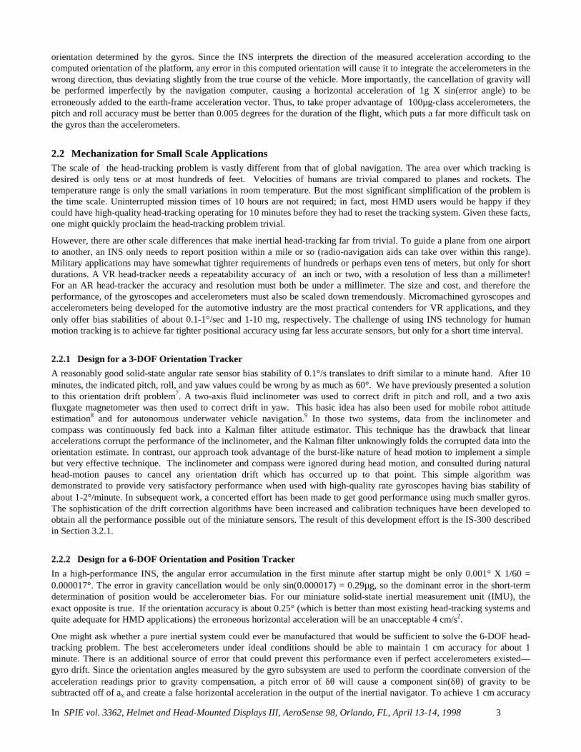
3.1.1 InertiaCube™ integrated inertial instrumentBoth the sourceless orientation tracking and the hybrid 6-DOF tracking product configurations make use of an ultra-miniaturesmart sensor module called the InertiaCube. The InertiaCube is a monolithic part based on micro-electro-mechanical systems(MEMS) technology involving no spinning wheels that might generate noise, inertial forces and mechanical failures. TheInertiaCube simultaneously measures 9 physical properties, namely angular rates, linear accelerations, and magnetic fieldcomponents along all 3 axes. Micro-miniature vibrating elements are employed to measure all the angular rate componentsand linear accelerations, with integral electronics and solid-state magnetometers. The geometry and composition of theseelements are proprietary, but the functional performance of the multisensor unit can be understood sufficiently by reference tothe equivalent diagram in Figure 2.
Figure 3 illustrates the basic physical principal underlying all Coriolis vibratory gyros. Suppose that the tines of the tuningfork are driven by an electrostatic, electromagnetic or piezoelectric drive to oscillate in the plane of the fork. When the wholefork is rotated about its axis, the tines will experience a Coriolis force F = ω X v pushing them to vibrate perpendicular tothe plane of the fork. The amplitude of this out-of-plane vibration is proportional to the input angular rate, and it is sensed bycapacitive or inductive or piezoelectric means to measure the angular rate.
By way of comparison, a conventional inertial measurement unit (IMU) senses 6 of these properties using 6 separateinstruments (3 rate gyros and 3 linear accelerometers) each of which by itself would typically be larger, heavier, and moreexpensive than an InertiaCube. Unlike conventional rate gyro and accelerometer instruments, which must be
x-accel
x-gyro
z-gyro
z-accel
y-gyro y-accel
Y
Z
X
y-mag.
x-mag.
z-mag.
angular rate
driven vibration
sensedvibration
v
ω
F = ω X v
In SPIE vol. 3362, Helmet and Head-Mounted Displays III, AeroSense 98, Orlando, FL, April 13-14, 1998 5
Figure 2: Functional diagram of InertiaCube Figure 3: Principle of Coriolis vibratory gyroscope
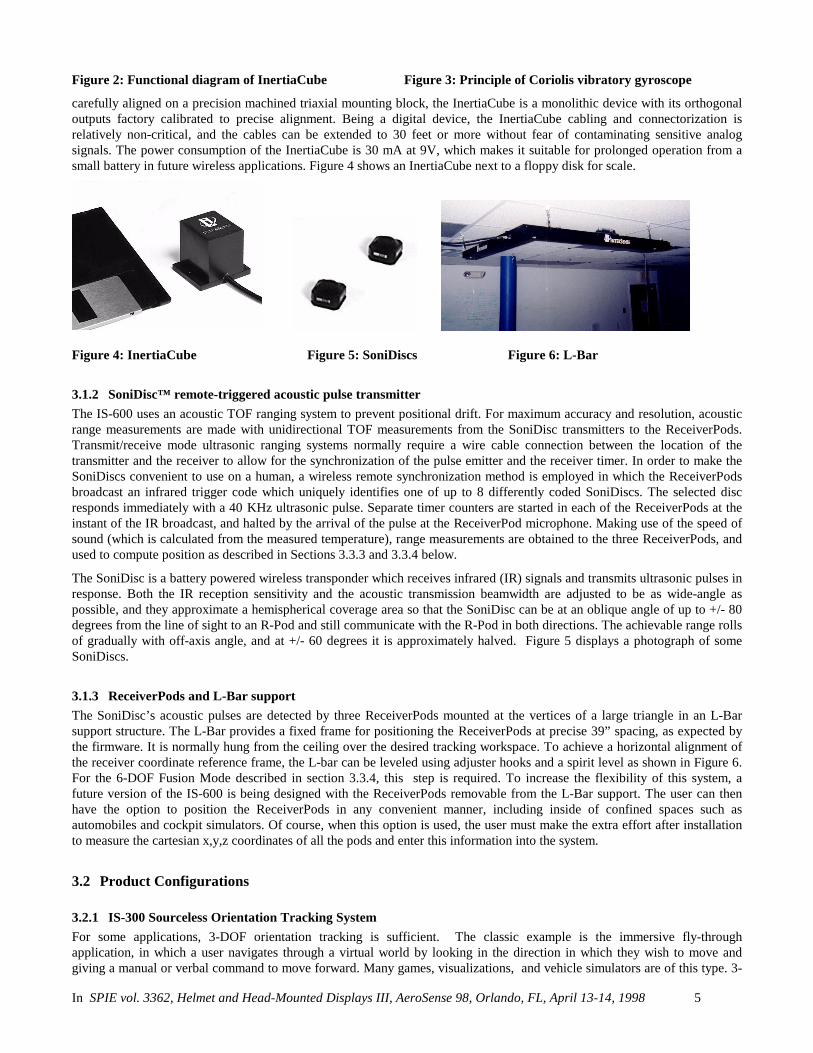
carefully aligned on a precision machined triaxial mounting block, the InertiaCube is a monolithic device with its orthogonaloutputs factory calibrated to precise alignment. Being a digital device, the InertiaCube cabling and connectorization isrelatively non-critical, and the cables can be extended to 30 feet or more without fear of contaminating sensitive analogsignals. The power consumption of the InertiaCube is 30 mA at 9V, which makes it suitable for prolonged operation from asmall battery in future wireless applications. Figure 4 shows an InertiaCube next to a floppy disk for scale.
Figure 4: InertiaCube Figure 5: SoniDiscs Figure 6: L-Bar
3.1.2 SoniDisc™ remote-triggered acoustic pulse transmitterThe IS-600 uses an acoustic TOF ranging system to prevent positional drift. For maximum accuracy and resolution, acousticrange measurements are made with unidirectional TOF measurements from the SoniDisc transmitters to the ReceiverPods.Transmit/receive mode ultrasonic ranging systems normally require a wire cable connection between the location of thetransmitter and the receiver to allow for the synchronization of the pulse emitter and the receiver timer. In order to make theSoniDiscs convenient to use on a human, a wireless remote synchronization method is employed in which the ReceiverPodsbroadcast an infrared trigger code which uniquely identifies one of up to 8 differently coded SoniDiscs. The selected discresponds immediately with a 40 KHz ultrasonic pulse. Separate timer counters are started in each of the ReceiverPods at theinstant of the IR broadcast, and halted by the arrival of the pulse at the ReceiverPod microphone. Making use of the speed ofsound (which is calculated from the measured temperature), range measurements are obtained to the three ReceiverPods, andused to compute position as described in Sections 3.3.3 and 3.3.4 below.
The SoniDisc is a battery powered wireless transponder which receives infrared (IR) signals and transmits ultrasonic pulses inresponse. Both the IR reception sensitivity and the acoustic transmission beamwidth are adjusted to be as wide-angle aspossible, and they approximate a hemispherical coverage area so that the SoniDisc can be at an oblique angle of up to +/- 80degrees from the line of sight to an R-Pod and still communicate with the R-Pod in both directions. The achievable range rollsof gradually with off-axis angle, and at +/- 60 degrees it is approximately halved. Figure 5 displays a photograph of someSoniDiscs.
3.1.3 ReceiverPods and L-Bar supportThe SoniDisc’s acoustic pulses are detected by three ReceiverPods mounted at the vertices of a large triangle in an L-Barsupport structure. The L-Bar provides a fixed frame for positioning the ReceiverPods at precise 39” spacing, as expected bythe firmware. It is normally hung from the ceiling over the desired tracking workspace. To achieve a horizontal alignment ofthe receiver coordinate reference frame, the L-bar can be leveled using adjuster hooks and a spirit level as shown in Figure 6.For the 6-DOF Fusion Mode described in section 3.3.4, this step is required. To increase the flexibility of this system, afuture version of the IS-600 is being designed with the ReceiverPods removable from the L-Bar support. The user can thenhave the option to position the ReceiverPods in any convenient manner, including inside of confined spaces such asautomobiles and cockpit simulators. Of course, when this option is used, the user must make the extra effort after installationto measure the cartesian x,y,z coordinates of all the pods and enter this information into the system.
3.2 Product Configurations
3.2.1 IS-300 Sourceless Orientation Tracking SystemFor some applications, 3-DOF orientation tracking is sufficient. The classic example is the immersive fly-throughapplication, in which a user navigates through a virtual world by looking in the direction in which they wish to move andgiving a manual or verbal command to move forward. Many games, visualizations, and vehicle simulators are of this type. 3-

In SPIE vol. 3362, Helmet and Head-Mounted Displays III, AeroSense 98, Orlando, FL, April 13-14, 1998 6
DOF orientation tracking is most effective with large scale virtual worlds, where the objects to be traveled amongst areusually some distance away. When dealing with small scale objects that the user tries to manipulate at arm’s distance, the lackof head-motion parallax can feel unnatural.
For applications which can work well with 3-DOF orientation tracking, there are some compelling advantages due to the“sourceless” nature of the Gyroscopic Earth-stabilized Orientation Sensing (GEOS™ ) paradigm described in section 3.3.1.First, since the sensing is based upon self-contained inertial angular rate sensors, with drift containment based on the earth’sgravitational and magnetic fields, the effective range of this tracker is most of the surface of the earth. Secondly, there are nosignificant interference sources to corrupt the accuracy of gravimetric vertical sensing. Even large mountains only deflect thegravitational vertical by a few arcseconds. Pitch and roll accuracy are therefore immune to any form of environmentalinterference. This is notable because pitch and roll errors can be perceived in an immersive HMD application, and aretherefore more important than yaw errors, which cannot. Due to it’s global range, the IS-300 is easily portable. An HMD withan InertiaCube in it can be quickly moved from one workstation to another without the need to also move and set up a source.
In order to realize the benefits of easy portability, substantial effort was invested to miniaturize the processing electronics unitfor the IS-300 and IS-300 PRO. Figure 7 illustrates the simple configuration of these products. The dotted lines indicate thatthe IS-300 PRO can be configured with one to four InertiaCube sensors, whereas the standard IS-300 only supports one.
I-Cube
I-Cube
I-Cube
I-Cube
IS-300 Processor Unit
serial data out
9 VDCPowerSupply orBattery
Figure 7: IS-300 HW diagram
3.2.2 IS-600 Acousto-Inertial Hybrid 6-DOF Tracking SystemFigure 8 illustrates the configuration of the hybrid acoustic/inertial tracking system. The IS-600 hardware is essentially asuperset of the IS-300, adding an ultrasonic range measurement system on top of the basic IS-300 PRO components. Thedrawing illustrates the IS-600 being used to track a helmet to which are attached an InertiaCube and two SoniDiscs. The rearSoniDisc has just received an infrared trigger code matching its internal ID, and is in the process of emitting anomnidirectional acoustic pulse of 40 KHz energy. The IR trigger code was broadcast widely from 3 IR LED banks located inthe ReceiverPods. Only one SoniDisc should be activated at a time.
I-Cube
I-Cube
I-Cube
IS-600 Processor Unit
serial data out
Receiver-Pod 1
Receiver-Pod 2 Receiver-Pod 3L-Bar
Figure 8: IS-600 HW diagram
The IS-600 has expansion capability up to 4 InertiaCubes and 8 SoniDiscs. The fact that these are packaged as separatemodules means that the user has the flexibility to configure the system for a very large variety of tracking tasks. The IS-600also has several additional operating modes in addition to the GEOS mode of the IS-300. These modes have different

In SPIE vol. 3362, Helmet and Head-Mounted Displays III, AeroSense 98, Orlando, FL, April 13-14, 1998 7
strengths and differing configuration requirements, and the following section is an attempt to clarify this potentially confusingaspect of the system.
3.3 Tracking ModesFor a motion tracking system, a station means an output data stream corresponding to one particular rigid object beingtracked. Some manufacturers refer to such a data channel as a sensor, which is perhaps more intuitive for a tracking system inwhich one physical sensor unit is always used to track one moving object. However, for an IS-600 tracking in a 6-DOF mode,it is necessary to attach multiple physical sensing devices (an InertiaCube and one or more SoniDiscs) to a single trackedentity. We therefore prefer the term station to reduce confusion.
For an IS-600, each station may be configured in one of the four tracking modes described below. Which tracking mode willbe used for a particular station depends on what hardware devices are assigned to that station:
hardware assigned to station: resulting tracking mode:
1 InertiaCube GEOS mode (3-DOF orientation tracking)
1 SoniDisc PULSAR mode (3-DOF position tracking)
1 InertiaCube AND 1 SoniDisc 6-DOF Dual mode
1 InertiaCube AND 2 or moreSoniDiscs
6-DOF Fusion mode
Table 1: Hardware assignments for each tracking mode
Recalling that the maximum complement of hardware for an IS-600 is up to 4 InertiaCubes and 8 SoniDiscs, an IS-600 couldbe configured for up to 12 3-DOF stations (4 GEOS and 8 PULSAR), or 4 6-DOF dual mode stations and 4 PULSARstations, or 4 Fusion mode stations. Since an IS-300/Pro has no SoniDiscs, all of its stations will be configured in GEOSmode by definition.
The following subsections will explain the algorithms of each mode and discuss the characteristics of the mode and trade-offsthat can be adjusted with options to that mode.
3.3.1 3-DOF Gyroscopic Earth-stabilized Orientation Sensing (GEOS) modeFigure 9 shows the processing which is used to compute orientation using this sensor configuration. The basic computation oforientation from gyroscopic angular rates (in the top line of boxes) provides the very rapid dynamic response and highresolution of the system. The accelerometers and magnetometers are used to stabilize the orientation to the earth’sgravitational and magnetic fields, thus eliminating the gradual but unbounded accumulation of gyroscopic drift errors. TheKalman filter uses an ever-evolving adaptive algorithm to discard the portion of the accelerometer measurements which aredue to actual motion instead of gravity.10 This is a very important step, because otherwise horizontal accelerations wouldresult in very large transient pitch and roll errors known to technical people as “slosh”. The low cost sourceless trackers usedin today’s consumer HMDs are inclinometer/compass devices, and are thus intrinsically slosh-prone to the point of beinguncomfortable to use unless you make a conscious effort to move your head slowly.
+
-InertiaCube
ωx, ωy, ωz
ax, ay, az
mx, my, mz
OrientationIntegration
OrientationPrediction
Kalman FilterOrientation ErrorEstimator
Perceptual Post-Filter (PPF)
Figure 9: GEOS mode tracking algorithm
In SPIE vol. 3362, Helmet and Head-Mounted Displays III, AeroSense 98, Orlando, FL, April 13-14, 1998 8
In GEOS mode, the reference frame (hereafter referred to as Navigation frame or Nav frame or N frame) is the locally-levelgeographic frame with its x-axis pointing north, y-axis east, and z-axis down. The Euler angles reported by the tracker can bedescribed as a sequence of rotations applied to the InertiaCube starting with its body axes initially aligned with the Nav frameaxes and resulting in the current orientation.
The line from the magnetic field sensor outputs of the InertiaCube to the Kalman filter is a dotted line to indicate that the useof the magnetometers may optionally be disabled. The accelerometer measurements are sufficient to correct all the drift inpitch and roll, and the geomagnetic compassing function is only used to correct drift in yaw. In many fly-through applicationsabsolute yaw referenced to magnetic north is not important and relative yaw tracking is sufficient. This is the case when theuser can turn to face an object or rotate the virtual world to bring that object into view. In these situations it may be desirableto turn magnetic yaw compensation off if there are large variations in the direction of magnetic north over the tracking area.With the compassing turned off, the yaw value will drift a few degrees per minute. This drift is too slow too notice while it ishappening, but the cumulative yaw error may eventually become noticeable if the user is seated in a fixed chair, and then itmay be necessary to send a Yaw Reset command. When yaw compensation mode is disabled, the Nav frame axes are alignedinstead to pseudo-north, pseudo-east, and down, where pseudo-north is simply the direction the InertiaCube x-axis was facingon power-up or after a Yaw Reset command.
The Perceptual Post-Filter (PPF) indicated with dotted lines is an optional filter provided for HMD tracking and similarapplications which is designed to make the output data minimize perceivable errors rather than minimize mean square errors.Since the human observer is more sensitive to jitter and drift when still or moving slowly, the PPF uses adaptive filtering topreferentially suppress these effects as the head slows down. Interestingly, the PPF only filters the corrections to orientationmade by the error estimator, and not the orientation signals themselves. Therefore, the trade-off is increased dynamic error,and not increased latency. If a head at rest suddenly makes a rapid movement, there will be no additional latency imposed bythe PPF in the all-important head-motion-to-visual-feedback sensorimotor loop. The PPF is a constantly evolving family offuzzy rule-based algorithms which have been quite successful in eliminating most perceivable jitter and drift withoutintroducing any latency.
The GEOS mode update rate is the fastest of the four modes. It provides complete orientation updates at 500 Hz on an IS-600or an IS-300 PRO, and at 150 Hz on an IS-300.
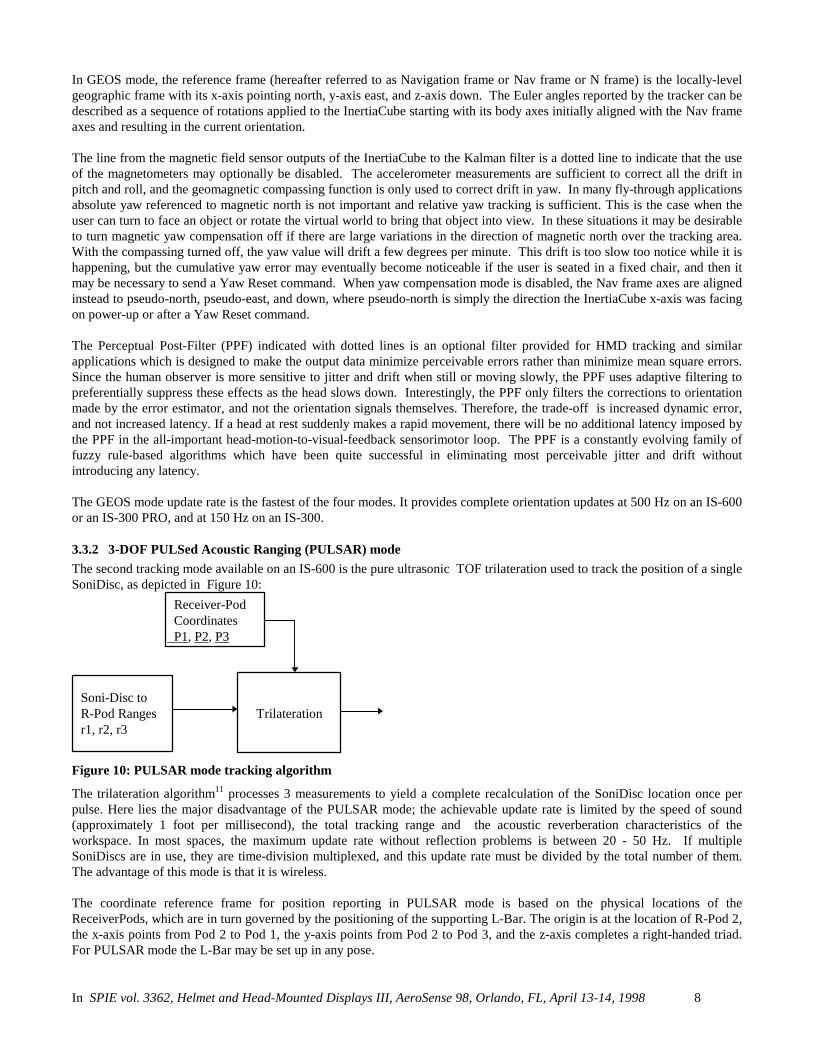
3.3.2 3-DOF PULSed Acoustic Ranging (PULSAR) modeThe second tracking mode available on an IS-600 is the pure ultrasonic TOF trilateration used to track the position of a singleSoniDisc, as depicted in Figure 10:
Soni-Disc toR-Pod Rangesr1, r2, r3
Trilateration
Receiver-Pod Coordinates P1, P2, P3
Figure 10: PULSAR mode tracking algorithm
The trilateration algorithm11 processes 3 measurements to yield a complete recalculation of the SoniDisc location once perpulse. Here lies the major disadvantage of the PULSAR mode; the achievable update rate is limited by the speed of sound(approximately 1 foot per millisecond), the total tracking range and the acoustic reverberation characteristics of theworkspace. In most spaces, the maximum update rate without reflection problems is between 20 - 50 Hz. If multipleSoniDiscs are in use, they are time-division multiplexed, and this update rate must be divided by the total number of them.The advantage of this mode is that it is wireless.
The coordinate reference frame for position reporting in PULSAR mode is based on the physical locations of theReceiverPods, which are in turn governed by the positioning of the supporting L-Bar. The origin is at the location of R-Pod 2,the x-axis points from Pod 2 to Pod 1, the y-axis points from Pod 2 to Pod 3, and the z-axis completes a right-handed triad.For PULSAR mode the L-Bar may be set up in any pose.

In SPIE vol. 3362, Helmet and Head-Mounted Displays III, AeroSense 98, Orlando, FL, April 13-14, 1998 9
3.3.3 6-DOF Dual modeSix-DOF Dual mode uses the GEOS mode for tracking orientation and the PULSAR mode for tracking position. TheInertiaCube and the SoniDisc are tracked completely independently, and inherit all the characteristics described aboveincluding the unrelated coordinate reference frames. If the L-Bar is mounted level, with one leg pointing north and the otherpointing east, then position and orientation data will be reported in the same coordinate system. This mode is used when youwant fast, smooth orientation tracking with prediction, and you also need some positional tracking but position update rate isnot critical enough to warrant mounting multiple SoniDiscs on the station.
3.3.4 6-DOF Fusion modeThe 6-DOF Fusion mode works like an inertial navigation system with acoustic range measurements to curtail drift in bothposition and orientation. Figure 11 illustrates the signal flow in this mode. The same InertiaCube is used as in GEOS mode,but its outputs are processed somewhat differently. The angular rate signals are integrated in a direct manner to obtainorientation, as with GEOS. The linear acceleration signals are used simultaneously for two separate purposes. First, they aretransformed from the InertiaCube body frame (B-frame) into a locally-level navigation frame (N-frame). The gravitationconstant, g, is then subtracted from the vertical acceleration component in order to cancel the unwanted effects of gravity onthe accelerometer triad. Then the remaining acceleration vector is double integrated to track changes in the N-frame position.In a second usage, the B-frame accelerations are also fed into the error estimator to help cancel pitch and roll drift, analogousto the way they are used in GEOS mode. Finally, note that the magnetic field components sensed by the InertiaCube are notused at all in Fusion mode.
Instead, the yaw drift is corrected by the acoustic range measurements simultaneously with the position drift. This is why it isnecessary to have at least two SoniDiscs associated with a Fusion mode station. Although what happens inside the extendedKalman filter is actually quite different, the simplified explanation is that the acoustic range measurements can be used tofirst localize one SoniDisc, then the second, find the vector connecting them and determine a heading direction from it withwhich to reset the yaw drift. Depending on the baseline separation between the SoniDiscs and the number present, the EKFmay also partially or fully override the pitch and roll corrections that the accelerometers make.
I-Cube
ωx, ωy, ωz
ax, ay, az
OrientationIntegration
OrientationPrediction[& PPF]
CoordinateTransform
PositionPrediction[& PPF]
-g
EKF Orientation andPosition Error Estimator
DoubleIntegration
Acoustic RangeMeasurements r1, r2, r3
Figure 11: Fusion mode tracking algorithm
The reference frame for both position and orientation tracking is a locally-level frame with the z-axis pointing down. Thedirection of the x and y axes is determined by the orientation of the L-bar. The L-Bar must be hung level as described inSection 3.1.3 because otherwise there will be conflicting orientation correcting information provided by the accelerometersand the acoustic system, which could lead to output oscillations. If it is not desirable to hang the L-Bar horizontally, then the3-D coordinates of the R-Pods can be digitized or calculated in a locally level frame N, and downloaded into the tracker. Thisthen establishes N as the navigation frame.
As shown in Table 1, a Fusion mode station must be equipped with an InertiaCube and two or more SoniDiscs. Thesecomponents are mounted on a rigid object to be tracked, and then the positions of the SoniDiscs with respect to the B-frameaxes of the InertiaCube are measured and entered into the tracker. The origin and axes of the tracked station, for the purposesof tracking, will be those of the InertiaCube. At least two SoniDiscs are necessary so that an acoustically-derived yawdirection can be established and used to align the reference frame for the strapdown inertial subsystem with the reference

In SPIE vol. 3362, Helmet and Head-Mounted Displays III, AeroSense 98, Orlando, FL, April 13-14, 1998 10
frame of the acoustic range-measuring system. Without this alignment, the accelerometers would indicate translational motionin a conflicting direction from the acoustic subsystem.
Six-DOF Fusion mode takes a little more care to set up, but provides some significant performance advantages:• Yaw drift correction is accomplished by ultrasonic rather than magnetic means, and it therefore works very accurately
even in poor magnetic environments.• If using 3 SoniDiscs spread out in a sufficiently large triangle, pitch and roll accuracy may be improved compared to
GEOS mode.• Position update rate can be maintained at 150 Hz, even when using multiple SoniDiscs.• Position tracking resolution and accuracy are superior to PULSAR mode.• Prediction can be applied to position as well as orientation.• Position tracking can continue without interruption during brief occlusions of the ultrasonic LOS.
4. PERFORMANCE EVALUATIONIn this section we evaluate the performance of an IS-600 system in GEOS mode and Fusion mode. The testing is performedwith one particular randomly selected InertiaCube. Therefore this data should not be construed as a specification providingworst-case bounds on the performance of the product, but rather representative sample data.
4.1 Terminology & MethodsA standard measuring system, say a caliper, is characterized by its resolution and static accuracy. A dynamic measuringsystem, such as a motion tracker, is additionally concerned with dynamic accuracy, and latency.
Resolution is the smallest change of the measured property that the system is able to detect. In most systems, the resolution iseither limited by the output quantization units, or the output noise level. In the case of most motion trackers, including thosediscussed in this paper, the resolution is limited by the noise, which is often called jitter because of the visual effect the noisehas on the computer graphic display. Static accuracy is the amount of output error when the measured properties are heldconstant. The static absolute accuracy encompasses both non-repeatability and repeatable errors. Non-repeatability isprimarily caused by hysteresis and drift. Repeatable error is due to constant input/output distortions such as bias, scale factorerror, nonlinearity, and cross-axis sensitivity.
Both jitter and drift are measured simply by placing the tracking sensor set at rest on a non-moving surface and recording theoutput data stream for a period of time. Jitter is mainly important because of the rapidly shaking imagery it creates, so weexclude the near-DC component of the still-sensor output data stream from the jitter data below. This extreme low-frequencycomponent represents a slowly undulating output error, that we will categorize under the term stationary drift or boundeddrift. The typical drift of integrated rate sensors or accelerometers resembles a random walk process, which tends to growlarger and larger over an extended period of time, and thus must be measured in degrees/second instead of just degrees. Thiswe call nonstationary drift or unbounded drift, and it is not present in the outputs of our drift-corrected inertial systems,except in the yaw output of GEOS mode when the use of the compass for yaw drift correction has been disabled. The cutofffrequency between jitter and bounded drift is somewhat arbitrary. In keeping with the connotations of the words jitter anddrift, we will consider any output motion that is so slow that it cannot be perceived except by waiting and comparing to amemorized previous position to be drift not jitter. We think most readers will agree that angular rotation slower than theminute-hand of a clock (6 degrees/minute) and linear translation slower than 1 cm/minute satisfy this description.
Static accuracy is the root-mean-square (RMS) deviation of reported angles or positions from the true ones when the sensorset is held at a fixed known pose. To measure static accuracy, one needs a "truth" reference that can be relied upon to beconsiderably more accurate than the system under test. The static accuracy may vary considerably depending on the pose. Wetherefore desired a truth reference that could be reconfigured to a large variety of known fixed orientations or positions. Forangular static accuracy testing, we used a stepper-motor controlled camera pan/tilt unit (PTU) from Directed Perception, Inc.(Burlingame, CA) mounted on a stable leveled tripod. The PTU, shown in Figure 12, is specified to have an accuracy of0.05°. For position testing, we taped a large sheet of paper with a precise 1 inch square grid plotted on it to the surface of aflat board leveled on a lab bench. This grid was then aligned with the origin and axes established by the L-bar hanging aboveit to an accuracy of about 0.05 inches by using plumb bobs. A 5-DOF articulated digitizer arm (MicroScribe from ImmersionCorp.) was registered to this coordinate frame, and then used for GEOS mode dynamic accuracy testing and for Fusion modestatic and dynamic accuracy testing.

In SPIE vol. 3362, Helmet and Head-Mounted Displays III, AeroSense 98, Orlando, FL, April 13-14, 1998 11
Figure 12: PTU for orientation static accuracy Figure 13: Arm for dynamic accuracy & latency
4.2 GEOS mode performanceTesting was performed on an InertiaCube performing orientation tracking in GEOS mode with the optional PPF turned off(aka jump mode). As shown if Figure 14, this resulted in r.m.s. jitter of 0.021 degrees and a slow bounded drift of about 0.05degrees maximum in one direction before reversing. Use of the PPF in “smooth mode” would result in substantially less jitter,but the dynamic accuracy would be worsened.
0 5 1 0 1 5 2 0 2 5 3 0 3 5 4 0- 0 . 1 5
- 0 . 1
- 0 . 0 5
0
0 . 0 5
0 . 1degrees
S t a t i c I -C u b e - j i t t e r a n d s t a t i o n a r y d r i f t
y a w
0 5 1 0 1 5 2 0 2 5 3 0 3 5 4 0- 0 . 0 5
0
0 . 0 5degrees
S t a t i o n a r y d r i f t - 0 t o 0 . 6 3 H z ( s l o w e r t h a n m i n u t e h a n d )
0 5 1 0 1 5 2 0 2 5 3 0 3 5 4 0- 0 . 1
- 0 . 0 5
0
0 . 0 5
0 . 1
t i m e ( s e c o n d s )
degrees
J i t t e r - 0 . 6 3 H z a n d a b o v e
1 s i g m a = 0 . 0 2 1
Figure 14: GEOS mode jitter and stationary drift
Figure 15 shows the results of a static accuracy test in which the PTU was rotated to 8 roll angles, and at each roll anglecycled through 6 pitch angles. The InertiaCube was subject to a quick recalibration procedure prior to the test, by placing it ona horizontal surface and removing residual accelerometer biases. The r.m.s. error in both pitch and roll was under 0.25degrees, averaged over all pitch and roll combinations.

In SPIE vol. 3362, Helmet and Head-Mounted Displays III, AeroSense 98, Orlando, FL, April 13-14, 1998 12
0 2000 4000 6000-40
-20
0
20
40Pitch
degrees
0 2000 4000 6000-50
0
50Roll
degrees
0 2000 4000 6000-0.5
0
0.5Pitch Error
samples
degrees
0 2000 4000 6000-0.5
0
0.5
1Roll Error
samples
degreessigma=0.119
sigma=0.127
Figure 15: GEOS mode static accuracy
Figure 16 shows the results of an orientation dynamic accuracy test performed by attaching the InertiaCube to the end of thedigitizer arm, and waving it fairly rapidly in the air.
0 0 . 5 1 1 . 5 2 2 . 5 3-2 0
0
2 0
4 0
6 0
8 0
arm
pitc
h an
d tra
cker
pitc
h (d
eg)
P i t c h d y n a m ic a c c u ra c y t e s t
0 0 . 5 1 1 . 5 2 2 . 5 3-2
-1 . 5
-1
-0 . 5
0
0 . 5
s e c o n d s
erro
r (de
gree
s)
Figure 16: GEOS mode dynamic accuracy

In SPIE vol. 3362, Helmet and Head-Mounted Displays III, AeroSense 98, Orlando, FL, April 13-14, 1998 13
4.3 Fusion mode performanceFusion mode results are shown for translational degrees of freedom only, since the orientation performance is not thatdifferent from GEOS mode. Again both the orientation and positition PPFs were disabled in order to show best dynamicaccuracy at the expense of higher jitter. Figure 17 shows the jitter during a 2 second stationary trial, yielding a standarddeviation (1 sigma) of about 0.5 mm for X and Y and 0.2 mm for Z.
0 1 20
0.1
0.2
0.3
0.4
0.5 X
cm
sigma = 0.0532512
0 1 20
0.1
0.2
0.3
0.4
0.5 Y
sigma = 0.0538524
0 1 20
0.1
0.2
0.3
0.4
0.5 Z
sigma = 0.0208548
seconds seconds seconds
Figure 17: Fusion mode jitter and stationary drift
Figure 18 and 19 show the static and dynamic accuracy of position tracking respectively, collected using a station consistingof 3 SoniDiscs and an InertiaCube mounted on a sheet metal triangle and attached to the end of the digitizer arm as shown ifFigure 13. The baseline separation of the SoniDiscs was about 30 cm. The static accuracy was sampled at 10 random X,Y,Zpositions, and indicates a deviation of about +/- 5 mm over this span, with an r.m.s. error of 3.3 mm. The dynamic accuracy isa little larger, with peak errors of about 1.5 cm during a fairly rapid movement sequence.
0 500 10000
20
40
60
80X
Pos
ition
(cm
)
0 500 10000
20
40
60
80Y
0 500 100090
100
110
120
130
140Z
0 500 1000-1
-0.5
0
0.5
Err
or(c
m)
s a m p les
rms = 0 .274037
0 500 1000-1
-0.5
0
0.5
1
s a m p les
rms = 0 .332445
0 500 10000
0.1
0.2
0.3
0.4
0.5
s a m p les
rms = 0 .269624
Figure 18: Fusion mode static accuracy
In SPIE vol. 3362, Helmet and Head-Mounted Displays III, AeroSense 98, Orlando, FL, April 13-14, 1998 14
0 2 42 0
2 5
3 0
3 5
4 0X
Pos
ition
(cm
)
0 2 42 0
2 5
3 0
3 5
4 0Y
0 2 49 5
1 0 0
1 0 5
1 1 0
1 1 5Z
0 2 4- 0 . 5
0
0 . 5
1
1 . 5
2
Err
or(c
m)
T i m e ( s )0 2 4
- 1
- 0 . 5
0
0 . 5
1
T i m e ( s )0 2 4
- 0 . 5
0
0 . 5
1
1 . 5
T i m e ( s )
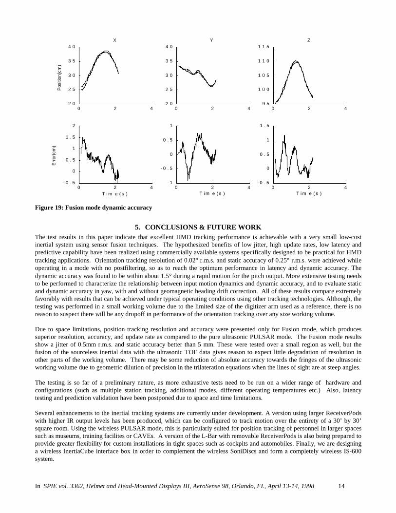
Figure 19: Fusion mode dynamic accuracy
5. CONCLUSIONS & FUTURE WORKThe test results in this paper indicate that excellent HMD tracking performance is achievable with a very small low-costinertial system using sensor fusion techniques. The hypothesized benefits of low jitter, high update rates, low latency andpredictive capability have been realized using commercially available systems specifically designed to be practical for HMDtracking applications. Orientation tracking resolution of 0.02° r.m.s. and static accuracy of 0.25° r.m.s. were achieved whileoperating in a mode with no postfiltering, so as to reach the optimum performance in latency and dynamic accuracy. Thedynamic accuracy was found to be within about 1.5° during a rapid motion for the pitch output. More extensive testing needsto be performed to characterize the relationship between input motion dynamics and dynamic accuracy, and to evaluate staticand dynamic accuracy in yaw, with and without geomagnetic heading drift correction. All of these results compare extremelyfavorably with results that can be achieved under typical operating conditions using other tracking technologies. Although, thetesting was performed in a small working volume due to the limited size of the digitizer arm used as a reference, there is noreason to suspect there will be any dropoff in performance of the orientation tracking over any size working volume.
Due to space limitations, position tracking resolution and accuracy were presented only for Fusion mode, which producessuperior resolution, accuracy, and update rate as compared to the pure ultrasonic PULSAR mode. The Fusion mode resultsshow a jitter of 0.5mm r.m.s. and static accuracy better than 5 mm. These were tested over a small region as well, but thefusion of the sourceless inertial data with the ultrasonic TOF data gives reason to expect little degradation of resolution inother parts of the working volume. There may be some reduction of absolute accuracy towards the fringes of the ultrasonicworking volume due to geometric dilution of precision in the trilateration equations when the lines of sight are at steep angles.
The testing is so far of a preliminary nature, as more exhaustive tests need to be run on a wider range of hardware andconfigurations (such as multiple station tracking, additional modes, different operating temperatures etc.) Also, latencytesting and prediction validation have been postponed due to space and time limitations.
Several enhancements to the inertial tracking systems are currently under development. A version using larger ReceiverPodswith higher IR output levels has been produced, which can be configured to track motion over the entirety of a 30’ by 30’square room. Using the wireless PULSAR mode, this is particularly suited for position tracking of personnel in larger spacessuch as museums, training facilites or CAVEs. A version of the L-Bar with removable ReceiverPods is also being prepared toprovide greater flexibility for custom installations in tight spaces such as cockpits and automobiles. Finally, we are designinga wireless InertiaCube interface box in order to complement the wireless SoniDiscs and form a completely wireless IS-600system.

In SPIE vol. 3362, Helmet and Head-Mounted Displays III, AeroSense 98, Orlando, FL, April 13-14, 1998 15
6. REFERENCES1. D. Bhatnagar, “Position trackers for head mounted display systems: a survey”, University of North Carolina - Chapel
Hill, TR93-010, 1993.2. F. Ferrin, “Survey of helmet tracking technologies”, SPIE, vol. 1456, pp 86-94, 1991.3. K. Meyer, H. Applewhite, and F. Biocca, “A survey of position trackers”, Presence, Vol. 1, pp. 173-200, 1992.4. K. Britting, “Inertial navigation systems analysis” , New York, Wiley Interscience, 1971.5. C. Broxmeyer, “Inertial navigation systems”, New York, McGraw-Hill, 1964.6. R. Parvin, “Inertial navigation”, Princeton, New Jersey, Van Nostrand, 1962.7. E. Foxlin, “Inertial head-tracking”, M.S. Thesis, Dept. of E.E.C.S., MIT, 1993.8. J. Vaganay, M. Aldon and A. Fournier, “Mobile robot attitude estimation by fusion of inertial data”, IEEE Intl. Conf. On
Robotics and Automation, vol. 1, 1993.9. E. Bachman, R. McGhee et al., “Evaluation of an integrated gps/ins system for shallow-water auv navigation (SANS),
Symposium on Autonomous Underwater Vehicle Technology, Monterey, CA, 1996.10. E. Foxlin, “Inertial head-tracker sensor fusion by a complementary separate-bias kalman filter”, Proc. VRAIS ’96 Virtual
Reality Annual Intl. Symposium, Santa Clara, CA 199611. D. Manolakis, “Efficient solution and performance analysis of 3-D position estimation by trilateration”, IEEE Trans.
Aerospace and Electronic Systems, vol. 32 no. 4, 1996.