Embed Size (px)
Citation preview

High-Efficiency Radius Cutter with Multiple Edges
MRWHigh-Efficiency Radius Cutter with Multiple Edges
Milling MRW
Economical 8-edge insertLow Cutting Force due to our helical cutting edge designHigher Stability with flat lock structure
NEW Applicable to a wide range of applications from steel to difficult-to-cut materials
For difficult-to-cut materialsPR1535 / CA6535
1
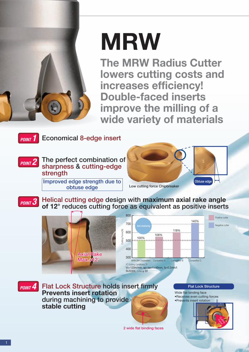
MRWThe MRW Radius Cutter lowers cutting costs and increases efficiency! Double-faced inserts improve the milling of a wide variety of materials
Economical 8-edge insert
The perfect combination of sharpness & cutting-edge strength
Flat Lock Structure holds insert firmlyPrevents insert rotation during machining to providestable cutting
Helical cutting edge design with maximum axial rake angle of 12° reduces cutting force as equivalent as positive inserts
Improved edge strength due to obtuse edge
Axial Rake Max.+12°
POINT 1
POINT 2
POINT 3
POINT 4
2 wide flat binding faces
Obtuse edgeLow cutting force Chipbreaker
Wide flat binding face •Receives even cutting forces•Prevents insert rotation
Flat Lock Structure
Cutting
Force
Cut
ting
Forc
e [N
]
100%108%
118%
140%
300
400
500
600
700
800
MRW (SM Chipbreaker) Competitor A Competitor B Competitor C
Positive cutter
Negative cutter
< Cutting Conditions >Vc=120m/min, ap ae=1 40mm, fz=0.2mm/tSUS304, Cutter φ 50
Anti-chattering
TiN
α-Al2O3
Special Interlayer
TiCN
Smoothness reduces adhesion and improves stability
Oxidation and wear resistant
Prevents peeling of coating layer
Resistant to friction-related wear
MRW High-Efficiency Radius Cutter with Multiple Edges
2
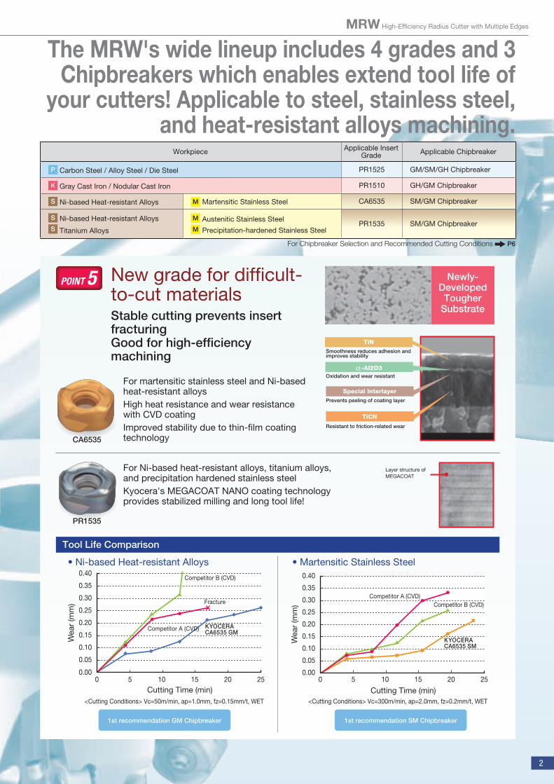
The MRW's wide lineup includes 4 grades and 3 Chipbreakers which enables extend tool life of
your cutters! Applicable to steel, stainless steel, and heat-resistant alloys machining.
Stable cutting prevents insert fracturingGood for high-efficiency machining
New grade for difficult-to-cut materials
For martensitic stainless steel and Ni-based heat-resistant alloysHigh heat resistance and wear resistance with CVD coatingImproved stability due to thin-film coating technology
For Ni-based heat-resistant alloys, titanium alloys, and precipitation hardened stainless steelKyocera's MEGACOAT NANO coating technology provides stabilized milling and long tool life!
Newly-Developed
Tougher Substrate
Tool Life Comparison
• Ni-based Heat-resistant Alloys • Martensitic Stainless Steel
POINT 5
Workpiece Applicable Insert Grade Applicable Chipbreaker
P Carbon Steel / Alloy Steel / Die Steel PR1525 GM/SM/GH Chipbreaker
K Gray Cast Iron / Nodular Cast Iron PR1510 GH/GM Chipbreaker
S Ni-based Heat-resistant Alloys M Martensitic Stainless Steel CA6535 SM/GM Chipbreaker
S Ni-based Heat-resistant AlloysS Titanium Alloys
M Austenitic Stainless SteelM Precipitation-hardened Stainless Steel
PR1535 SM/GM Chipbreaker
<Cutting Conditions> Vc=300m/min, ap=2.0mm, fz=0.2mm/t, WET
W
ear
(mm
)
Cutting Time (min)0
0.00
0.05
0.10
0.15
0.20
0.25
0.30
0.35
0.40
5 10 15 20 25
KYOCERACA6535 SM
Competitor A (CVD)Competitor B (CVD)
<Cutting Conditions> Vc=50m/min, ap=1.0mm, fz=0.15mm/t, WET
W
ear
(mm
)
Cutting Time (min)0
0.00
0.05
0.10
0.15
0.20
0.25
0.30
0.35
0.40
5 10 15 20 25
KYOCERACA6535 GM
Competitor A (CVD)
Fracture
Competitor B (CVD)
For Chipbreaker Selection and Recommended Cutting Conditions P6
CA6535
PR1535
Layer structure of MEGACOAT
1st recommendation GM Chipbreaker 1st recommendation SM Chipbreaker
3
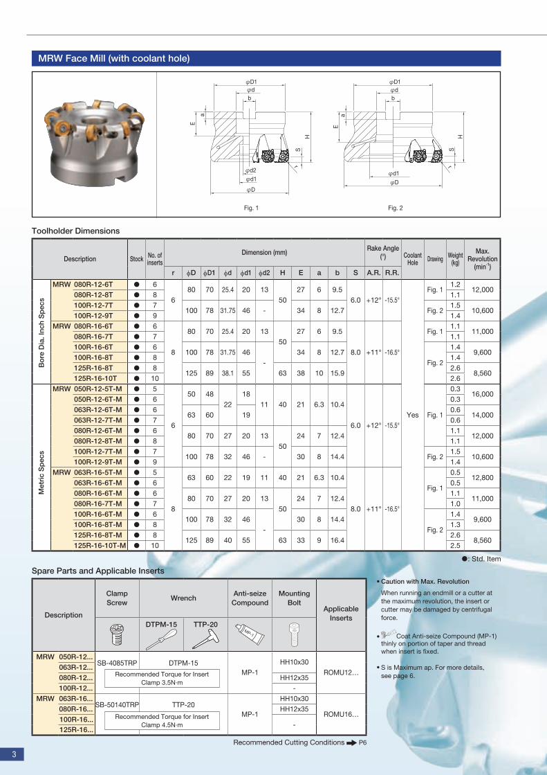
Toolholder Dimensions
: Std. Item
MRW Face Mill (with coolant hole)
HS
r
Ea
bφd
φd1
φD
φd2φd1
φD
φd
H
S
r
b
φD1 φD1
a
E
Fig. 1 Fig. 2
Spare Parts and Applicable Inserts
Description Stock No. of inserts
Dimension (mm) Rake Angle (°) Coolant
Hole Drawing Weight (kg)
Max. Revolution
(min-1)r fD fD1 fd fd1 fd2 H E a b S A.R. R.R.
MRW 080R-12-6T ● 6
680 70 25.4 20 13
5027 6 9.5
6.0 +12° -15.5°
Yes
Fig. 11.2
12,000 080R-12-8T ● 8 1.1100R-12-7T ● 7
100 78 31.75 46 - 34 8 12.7 Fig. 21.5
10,600 100R-12-9T ● 9 1.4
MRW 080R-16-6T ● 6
8
80 70 25.4 20 1350
27 6 9.5
8.0 +11° -16.5°
Fig. 11.1
11,000 080R-16-7T ● 7 1.1100R-16-6T ● 6
100 78 31.75 46-
34 8 12.7Fig. 2
1.49,600
100R-16-8T ● 8 1.4125R-16-8T ● 8
125 89 38.1 55 63 38 10 15.92.6
8,560 125R-16-10T ● 10 2.6
MRW 050R-12-5T-M ● 5
6
50 4822
1811 40 21 6.3 10.4
6.0 +12° -15.5°Fig. 1
0.316,000
050R-12-6T-M ● 6 0.3063R-12-6T-M ● 6
63 60 190.6
14,000 063R-12-7T-M ● 7 0.6080R-12-6T-M ● 6
80 70 27 20 1350
24 7 12.41.1
12,000 080R-12-8T-M ● 8 1.1100R-12-7T-M ● 7
100 78 32 46 - 30 8 14.4 Fig. 21.5
10,600 100R-12-9T-M ● 9 1.4
MRW 063R-16-5T-M ● 5
8
63 60 22 19 11 40 21 6.3 10.4
8.0 +11° -16.5°
Fig. 1
0.512,800
063R-16-6T-M ● 6 0.5080R-16-6T-M ● 6
80 70 27 20 1350
24 7 12.41.1
11,000 080R-16-7T-M ● 7 1.0100R-16-6T-M ● 6
100 78 32 46-
30 8 14.4Fig. 2
1.49,600
100R-16-8T-M ● 8 1.3125R-16-8T-M ● 8
125 89 40 55 63 33 9 16.42.6
8,560 125R-16-10T-M ● 10 2.5
Bo
re D
ia. I
nch
Sp
ecs
Met
ric
Sp
ecs
Description
Clamp Screw
WrenchAnti-seize
CompoundMounting
BoltApplicable
InsertsDTPM-15 TTP-20
MRW 050R-12...SB-4085TRP DTPM-15
MP-1HH10x30
ROMU12…063R-12...080R-12... HH12x35100R-12... -
MRW 063R-16...SB-50140TRP TTP-20
MP-1
HH10x30
ROMU16…080R-16... HH12x35100R-16...
-125R-16...
Recommended Torque for Insert Clamp 3.5N∙m
Recommended Torque for Insert Clamp 4.5N∙m
Recommended Cutting Conditions P6
Caution with Max. Revolution
When running an endmill or a cutter at the maximum revolution, the insert or cutter may be damaged by centrifugal force.
Coat Anti-seize Compound (MP-1) thinly on portion of taper and thread when insert is fixed.
S is Maximum ap. For more details, see page 6.
•
•
•
MRW High-Efficiency Radius Cutter with Multiple Edges
4
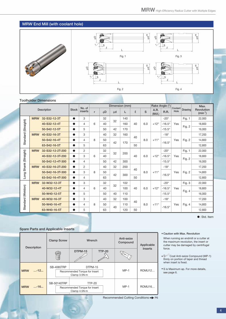
Toolholder Dimensions
: Std. Item
MRW End Mill (with coolant hole)
Lℓ
r S
φd
φD
h6
Lℓ
r S
φd
φD
h6
φd
h6
Lℓ
rφ
D
S
φd
h6
Lℓ
rφ
D
S
Fig. 1 Fig. 3
Fig. 2 Fig. 4
Spare Parts and Applicable Inserts
Description
Clamp Screw WrenchAnti-seize
CompoundApplicable
InsertsDTPM-15 TTP-20
MRW …-12...SB-4085TRP DTPM-15
MP-1 ROMU12…
MRW …-16...SB-50140TRP TTP-20
MP-1 ROMU16…
Recommended Torque for Insert Clamp 3.5N∙m
Recommended Torque for Insert Clamp 4.5N∙m
Description Stock No. of inserts
Dimension (mm) Rake Angle (°)Coolant
Hole DrawingMax.
Revolution (min-1)r fD fd L ℓ S
A.R.(MAX.)
R.R.
MRW 32-S32-12-3T ● 3
6
3232
140
40 6.0 +12°
-20°
Yes
Fig. 1 22,000
40-S32-12-4T ● 4 40 160 -16.5°Fig. 2
18,800
50-S42-12-5T ● 5 50 42 170 -15.5° 16,000
MRW 40-S32-16-3T ● 3
8
40 32 16040
8.0 +11°
-18°
Yes Fig. 2
17,200
50-S42-16-4T ● 4 5042 170 -16.5°
14,800
63-S42-16-5T ● 5 63 50 12,800
MRW 32-S32-12-2T-200 ● 2
6
3232 200
40 6.0 +12°
-20°
Yes
Fig. 1 22,000
40-S32-12-3T-200 ● 3 40 -16.5°Fig. 2
18,800
50-S42-12-4T-300 ● 4 50 42 300 -15.5° 16,000
MRW 40-S32-16-2T-200 ● 2
8
40 32 20040
8.0 +11°
-18°
Yes Fig. 2
17,200
50-S42-16-3T-300 ● 3 5042 300 -16.5°
14,800
63-S42-16-4T-300 ● 4 63 50 12,800
MRW 32-W32-12-3T ● 3
6
3232
102
40 6.0 +12°
-20°
Yes
Fig. 3 22,000
40-W32-12-4T ● 4 40 100 -16.5°Fig. 4
18,800
50-W40-12-5T ● 5 50 40 110 -15.5° 16,000
MRW 40-W32-16-3T ● 3
8
40 32 10040
8.0 +11°
-18°
Yes Fig. 4
17,200
50-W40-16-4T ● 4 5040
110-16.5°
14,800
63-W40-16-5T ● 5 63 120 50 12,800
Sta
ndar
d (S
trai
ght
)Lo
ng S
hank
(Str
aig
ht)
Sta
ndar
d (W
eld
on)
Recommended Cutting Conditions P6
Caution with Max. Revolution
When running an endmill or a cutter at the maximum revolution, the insert or cutter may be damaged by centrifugal force.
Coat Anti-seize Compound (MP-1) thinly on portion of taper and thread when insert is fixed.
S is Maximum ap. For more details, see page 6.
•
•
•
5
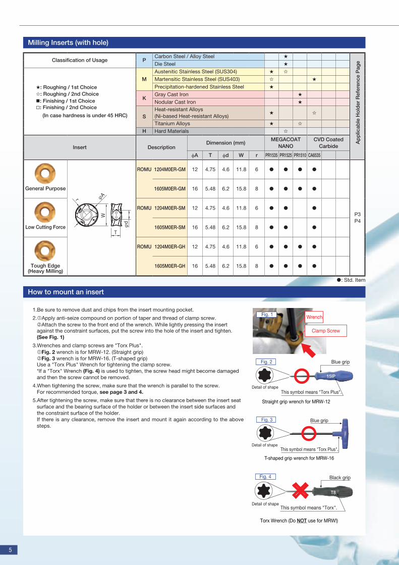
Classification of Usage PCarbon Steel / Alloy Steel ★
Die Steel ★
★: Roughing / 1st Choice✩: Roughing / 2nd Choice: Finishing / 1st Choice: Finishing / 2nd Choice
(In case hardness is under 45 HRC)
MAustenitic Stainless Steel (SUS304) ★ ✩
Martensitic Stainless Steel (SUS403) ✩ ★
Precipitation-hardened Stainless Steel ★
KGray Cast Iron ★
Nodular Cast Iron ★
SHeat-resistant Alloys (Ni-based Heat-resistant Alloys)
★ ✩
Titanium Alloys ★ ✩
H Hard Materials ✩
Insert DescriptionDimension (mm)
MEGACOAT NANO
CVD Coated Carbide
fA T fd W r PR1535 PR1525 PR1510 CA6535
General Purpose
φd
φA
T
W
r
ROMU 1204M0ER-GM 12 4.75 4.6 11.8 6 ● ● ● ●
P3P4
1605M0ER-GM 16 5.48 6.2 15.8 8 ● ● ● ●
Low Cutting Force
ROMU 1204M0ER-SM 12 4.75 4.6 11.8 6 ● ● ●
1605M0ER-SM 16 5.48 6.2 15.8 8 ● ● ●
Tough Edge (Heavy Milling)
ROMU 1204M0ER-GH 12 4.75 4.6 11.8 6 ● ● ● ●
1605M0ER-GH 16 5.48 6.2 15.8 8 ● ● ● ●
Milling Inserts (with hole)
How to mount an insert
1.Be sure to remove dust and chips from the insert mounting pocket.
2.Apply anti-seize compound on portion of taper and thread of clamp screw.Attach the screw to the front end of the wrench. While lightly pressing the insert against the constraint surfaces, put the screw into the hole of the insert and tighten. (See Fig. 1)
3.Wrenches and clamp screws are "Torx Plus".Fig. 2 wrench is for MRW-12. (Straight grip)Fig. 3 wrench is for MRW-16. (T-shaped grip)Use a "Torx Plus" Wrench for tightening the clamp screw.*If a "Torx" Wrench (Fig. 4) is used to tighten, the screw head might become damaged and then the screw cannot be removed.
4.When tightening the screw, make sure that the wrench is parallel to the screw.For recommended torque, see page 3 and 4.
5.After tightening the screw, make sure that there is no clearance between the insert seat surface and the bearing surface of the holder or between the insert side surfaces and the constraint surface of the holder.If there is any clearance, remove the insert and mount it again according to the above steps.
Clamp Screw
Wrench Fig. 1
Straight grip wrench for MRW-12
Detail of shape
Blue grip
This symbol means "Torx Plus".
Fig. 2
15IP
T-shaped grip wrench for MRW-16
Detail of shape
Blue grip
This symbol means "Torx Plus".
Fig. 3
T8
Black grip
This symbol means "Torx".Detail of shape
Torx Wrench (Do NOT use for MRW!)
Fig. 4
: Std. Item
Ap
plic
able
Ho
lder
Ref
eren
ce P
age
MRW High-Efficiency Radius Cutter with Multiple Edges
6
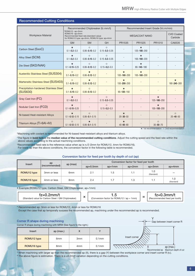
Recommended Cutting Conditions
*Machining with coolant is recommended for Ni-based heat-resistant alloys and titanium alloys.
*The figure in bold font is the median value of the recommended cutting conditions. Adjust the cutting speed and the feed rate within the above values according to the actual machining conditions.
*Recommended feed rate is the reference value when ap is rε/2 (3mm for ROMU12, 4mm for ROMU16).For lower ap than the above conditions, the conversion factor in the following table is recommended.
★: 1st recommendation ✩: 2nd recommendation
Insert ap (recommended) ap (max)
Conversion factor for feed per tooth
ap=0.5mm ap=1mm ap=2mm ap=3mm ap=4mm
ROMU12 type 3mm or less 6mm 2.1 1.5 1.1 1.0(Standard)
—
ROMU16 type 4mm or less 8mm 2.4 1.7 1.3 1.1 1.0(Standard)
• Example (ROMU12 type, Carbon Steel, GM Chipbreaker, ap=1mm)
Conversion factor for feed per tooth by depth of cut (ap)
Workpiece Material
Recommended Chipbreaker (fz mm/t)*ROMU12∙∙∙ap=3mmROMU16∙∙∙ap=4mm Recommended feed rate (standard value)for ROMU12 type: ap=3mm, ROMU16 type: ap=4mm
Recommended Insert Grade (Vc:m/min)
MEGACOAT NANOCVD Coated
Carbide
GM SM GH PR1535 PR1525 PR1510 CA6535
Carbon Steel (SxxC)★
0.1~0.2~0.3✩
0.06~0.15~0.2✩
0.15~0.3~0.35-
★
120~180~250- -
Alloy Steel (SCM)★
0.1~0.2~0.3✩
0.06~0.15~0.2✩
0.15~0.3~0.35-
★
100~160~220- -
Die Steel (SKD/NAK)★
0.1~0.15~0.25✩
0.06~0.12~0.2✩
0.15~0.2~0.3-
★
80~140~180- -
Austenitic Stainless Steel (SUS304)✩
0.1~0.15~0.2★
0.06~0.12~0.2-
★
100~160~200★
100~160~200- -
Martensitic Stainless Steel (SUS403)✩
0.1~0.15~0.2★
0.06~0.12~0.2-
★
150~200~250- -
★
180~240~300
Precipitation-hardened Stainless Steel
(SUS630)★
0.1~0.15~0.2✩
0.06~0.12~0.2-
★
90~120~150- - -
Gray Cast Iron (FC)★
0.1~0.2~0.3-
✩
0.15~0.3~0.35- -
★
120~180~250-
Nodular Cast Iron (FCD)★
0.1~0.15~0.25-
✩
0.15~0.2~0.3- -
★
100~150~200-
Ni-based Heat-resistant Alloys★
0.1~0.12~0.15✩
0.06~0.1~0.15-
★
20~30~50- -
✩
20~40~50
Titanium Alloys (Ti-6Al-4V)✩
0.1~0.12~0.15★
0.06~0.1~0.15-
★
40~60~80-
✩
30~50~70-
Insert ap (max.) X Y
ROMU12 type 6mm 3mm 0.1mm
ROMU16 type 8mm 4mm 0.1mm
* When machining with larger ap than the recommended ap (X), there is a gap (Y) between the workpiece corner and insert corner R (rε).* The above figure is estimation. There is a ±0.2mm variation depending on the cutting conditions.
Corner R shape during machiningCorner R shape during machining with MRW (See figure to the right.)
Insert corner
YGap between insert corner R
ap (max.)Maximum depth of cut
XRecommended ap
* Recommended ap: 3mm or less for ROMU12, 4mm or less for ROMU16 Except the case that ap temporally surpass the recommended ap, machining under the recommended ap is recommended.
fz=0.2mm/t (Standard value for Carbon Steel / GM Chipbreaker)
fz=0.3mm/t (Recommended feed per tooth)
1.5 (Conversion factor for ROMU12 / ap = 1mm)× =
CP312-2EN
12Cr Steel12Cr Steel
Turbine Blade Vc=270m/min fz=0.278mm/tap=0.5~1.0mm ae=max.35mm DryMRW050R-12-6T-M (6 inserts) ROMU1204M0ER-SM (CA6535)
The MRW improved machining efficiency by 1.2 times with the same tool life compared with Competitor A.The MRW has a cost advantage due to its double-sided inserts.
Turbine Blade Vc=250m/min fz=0.16mm/tap=2.0mm ae=5~30mm WetMRW050R-12-5T-M (5 inserts) ROMU1204M0ER-SM (CA6535)
The MRW showed less damage on the cutting edge and reduced cutting noise.The MRW has equal or longer tool life and a cost advantage due to its double-sided inserts.
CA6535 Stable, available for further machining
Competitor B (Positive cutter) Unstable machining with loud noise
CA6535 Stable Machining
Competitor A (Positive cutter) Unstable machining with loud noise
Same or longer tool lifeEconomical double-faced insert
1.2 times the machining efficiencyEconomical double-faced insert
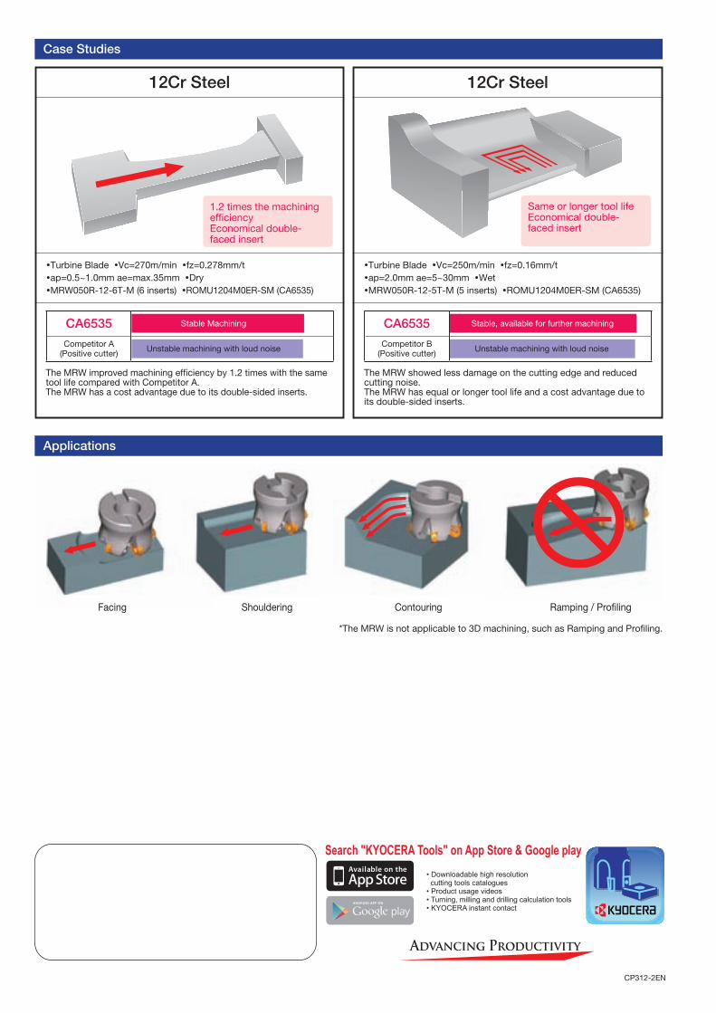
Case Studies
Applications
*The MRW is not applicable to 3D machining, such as Ramping and Profiling.
Facing Shouldering Contouring Ramping / Profiling