Embed Size (px)
Citation preview

MILLING MACHINE TRAIN THE TRAINER (SAFETY, PARTS & OPERATION) This material was produced under Susan Harwood grant number SH-31214-SH4 Occupational Safety and Health Administration, U.S. Department of Labor. The contents in this presentation do not necessarily reflect the views or policies of the U.S. Department of Labor, nor does the mention of trade names, commercial products, or organizations imply endorsement by the U.S. Government. CONTENT VISUALS TRAINER NOTES 1 SAFETY FIRST 2 WHO IS OSHA
With the Occupational Safety and Health Act of 1970, Congress created the Occupational Safety and Health Administration (OSHA) to assure safe and healthful working conditions for working men and women by setting and enforcing standards and by providing training, outreach, education and assistance.
OSHA is part of the United States Department of Labor. The administrator for OSHA is the Assistant Secretary of Labor for Occupational Safety and Health. OSHA's administrator answers to the Secretary of Labor, who is a member of the cabinet of the President of the United States.
3 KNOW YOUR RIGHTS Under federal law, you are entitled to a safe workplace. Your employer must provide a workplace free of known health and safety hazards. If you have concerns, you have the right to speak up about them without fear of retaliation. You also have the right to: ● Be trained in a language you
understand ● Work on machines that are safe ● Be provided required safety gear, such
as gloves or a harness and lifeline for falls
● Be protected from toxic chemicals ● Request an OSHA inspection, and
speak to the inspector ● Report an injury or illness, and get
copies of your medical records ● See copies of the workplace injury and
illness log ● Review records of work-related
injuries and illnesses ● Get copies of test results done to find
Read the rights to the trainees and point them to the posters available around the workplace where they can refer to for more information. Extra resources can be found at https://www.osha.gov/workers/index.html

hazards in the workplace 4 INTRODUCTION TO MILLING MACHINE
(Machine Guarding)
5 WHAT IS MACHINE GUARDING
Machine guarding is a means of shielding employees from moving or flying parts and preventing them from accidentally coming into contact with moving pieces of equipment.
6 MACHINE-RELATED INJURIES Possible machinery-related injuries include: ● Crushed fingers or hands ● Amputations ● Burns ● Blindness A good rule to remember is: Any machine part, function, or process which may cause injury must be safeguarded
Many accidents result from persons working on, or around, moving machinery. These accidents could have been prevented by the installation and proper maintenance of guarding. The goal of this training is to make the guarding of all equipment as easily understood as possible and re-inforce the safe working procedures that must always be in place around dangerous equipment. This list of accidents is as long as it is horrifying. Safeguards are essential for protecting workers from needless and preventable injuries. Where the operation of a machine can injure the operator or other workers,
the hazard must be controlled or eliminated. National Emphasis Program on Amputations*. CPL 03-00-019, (August 13, 2015). Describes policies and procedures for implementing a National Emphasis Program (NEP) to identify and to reduce workplace machinery and equipment hazards which are causing or likely to cause amputations. Resource: https://www.osha.gov/dte/outreach/construction_generalindustry/gi_outreach_tp.html https://safetyresourcesblog.com/2014/08/16/osha-quickcards-download-here-all-free-englishspanishother/
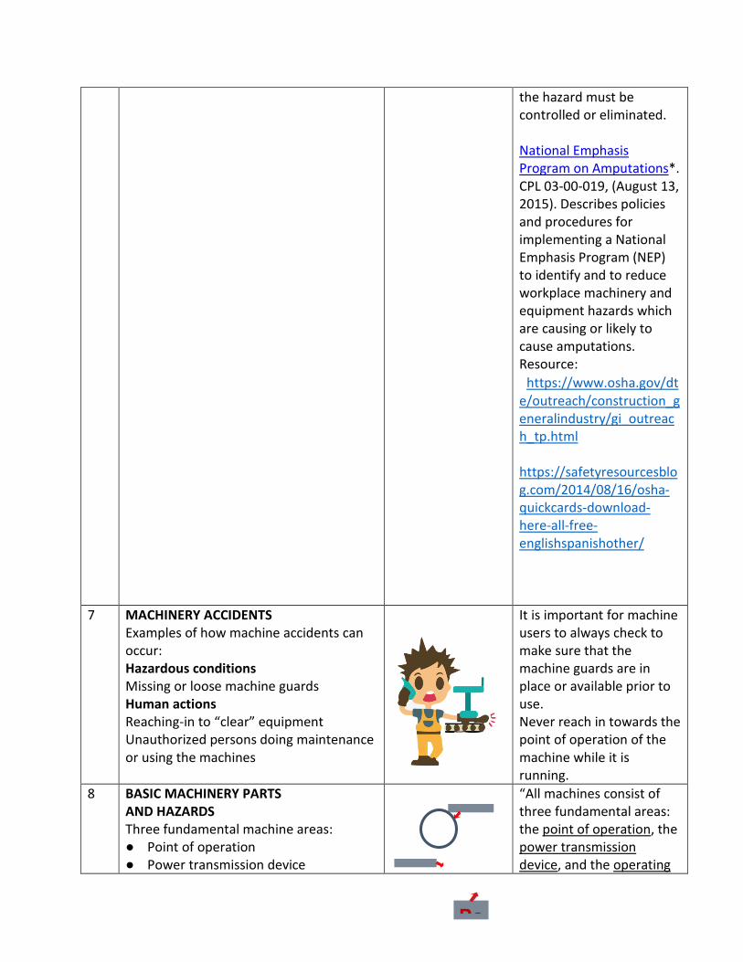
7 MACHINERY ACCIDENTS Examples of how machine accidents can occur: Hazardous conditions Missing or loose machine guards Human actions Reaching-in to “clear” equipment Unauthorized persons doing maintenance or using the machines
It is important for machine users to always check to make sure that the machine guards are in place or available prior to use. Never reach in towards the point of operation of the machine while it is running.
8 BASIC MACHINERY PARTS AND HAZARDS Three fundamental machine areas: ● Point of operation ● Power transmission device
“All machines consist of three fundamental areas: the point of operation, the power transmission device, and the operating
Po
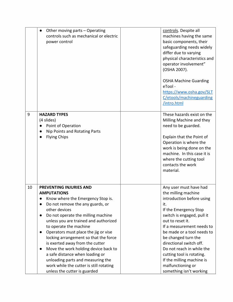
● Other moving parts – Operating controls such as mechanical or electric power control
controls. Despite all machines having the same basic components, their safeguarding needs widely differ due to varying physical characteristics and operator involvement” (OSHA 2007). OSHA Machine Guarding eTool - https://www.osha.gov/SLTC/etools/machineguarding/intro.html
9 HAZARD TYPES (4 slides) ● Point of Operation ● Nip Points and Rotating Parts ● Flying Chips
These hazards exist on the Milling Machine and they need to be guarded. Explain that the Point of Operation is where the work is being done on the machine. In this case it is where the cutting tool contacts the work material.
10 PREVENTING INJURIES AND AMPUTATIONS ● Know where the Emergency Stop is. ● Do not remove the any guards, or
other devices ● Do not operate the milling machine
unless you are trained and authorized to operate the machine
● Operators must place the jig or vise locking arrangement so that the force is exerted away from the cutter
● Move the work holding device back to a safe distance when loading or unloading parts and measuring the work while the cutter is still rotating unless the cutter is guarded
Any user must have had the milling machine introduction before using it. If the Emergency Stop switch is engaged, pull it out to reset it. If a measurement needs to be made or a tool needs to be changed turn the directional switch off. Do not reach in while the cutting tool is rotating. If the milling machine is malfunctioning or something isn’t working
● Do not reach around the cutter or hob to remove chips while the machine is in motion or not locked or tagged out
● If performing service and maintenance activities follow lock out tag out procedures
right let one of the shop staff know.
11 PROTECT YOURSELF WITH PPE ● Always wear safety glasses ● Always wear closed toe shoes that
protect the top of your foot ● Do not wear any rings or dangling
jewelry ● Long hair needs to be tied up or put
into a bun
Personal Protective Equipment may be a bit uncomfortable or bulky, but needs to be worn to protect the user from injury.
12 INTRODUCTION TO MILLING MACHINE 13 ORIGIN
A milling machine is a wheel-cutting machine, dating from the 1700s and used by clockmakers, were the precursors of industrial milling machines. Eli Whitney is most often mentioned as the first to design and construct a milling machine that was dependable, and which served as a prototype for later, improved cutting machines.
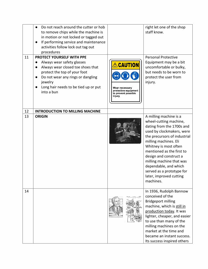
14 In 1936, Rudolph Bannow conceived of the Bridgeport milling machine, which is still in production today. It was lighter, cheaper, and easier to use than many of the milling machines on the market at the time and became an instant success. Its success inspired others

to copy the design, which lead to numerous clones.
15 WHAT IT DOES The milling machine’s high adaptability is demonstrated by the numerous cutting jobs it performs, including flat surfaces, grooves, shoulders, inclined surfaces, slots, and dovetails.
Commonly called "Bridgeport" style mills, these versatile mills are capable of performing many operations, including some that are similar to those performed on the drill press like drilling, reaming, countersinking, and counter boring. Other operations performed on the mill include but are not limited to side and face milling, fly cutting, and precision boring. Mills are classified on the basis of the position of their spindle. The spindle Operates in either a vertical or horizontal position. The amount of horsepower the mill is able to supply to the cutter is also often important. Source(s): http://www.bookrags.com/research/milling
16
IMPORTANT PARTS Motor Switch Turns the spindle on or off Emergency Stop Switch Cuts power to the spindle. Use only in emergencies Spindle Brake Brings the spindle to a stop when it is unpowered. Do not activate when spindle is powered Automatic Drawbar Controls Operates automatic drawbar mechanism
Point out the important parts of the machine as referenced by the picture.
for inserting and releasing tools Quill Feed Handle Lever This bar lets you lower or raise the tool Variable Speed Control This crank is used to change the speed of the spindle Traversal Cranks These cranks move the workpiece in the X, Y and Z directions Carriage Table Locks These can be engaged to prevent the X stage from moving
17 INTRODUCTION TO MILLING MACHINE (Safe Machine Operations)
18 VERTICAL MILL SAFETY The following rules should be observed when operating the machine:
The vertical mill is a safe machine, but only if the worker is aware of the hazards involved. You must always keep your mind on your work in order to avoid accidents. Distractions should be taken care of before machining begins. Develop safe working habits: Use safety glasses, setups and tools.
19 SAFE MACHINE OPERATIONS 1 Demonstrate loading a collet into the machine spindle.
Show the users where the R-8 collets are on the mills and how they differ from the lathe collets. Collets are predominantly used to hold end mills, drill chucks, and edge finders. The R-8 collet has a keyway in it that needs to line up with the key in the spindle. Gently push the collet into the spindle until it stops. Then rotate the collet by hand with light upward
pressure until the collet keyway engages with the spindle key.
20 SAFE MACHINE OPERATIONS 2 Verifying whether the machine is in Hi or Low gear. Caution: Do not turn the machine on.
Insert picture of gear selector in the Hi gear position. Also insert a picture of moving the gear selector lever and meshing the gear.
Verify that the gear selector is in High gear. If the machine is in low gear push the gear selector in and rotate it towards you to the High Gear location. If the gear selector lever doesn’t pop into the Hi Gear location the gears may not be meshed. To ensure that the gears mesh grab the spindle nose and rotate the spindle until the gear selector pops into the High Gear position.
21 SAFE MACHINE OPERATIONS 3 Loading an end mill into a collet and the machine spindle. Caution: End mills are sharp, do not run fingers over cutting edges. Caution: Do not confuse power draw bar controls with spindle on/off switch since this would cause contact at the Point of Operation. Do not get startled by the ratcheting sound of the collet closer.
Insert a picture of power draw bar buttons. Insert a picture of machine quill in home position.
The Power Draw Bar is used to tighten a collet and tool in the milling machines spindle nose. Show trainees where the power draw bar buttons are and how to activate them. Demonstrate how power draw bar works. Caution the trainees that the Power Draw Bar is loud and that they shouldn’t be frightened of it. The machine Quill must be all the way up to enable
the Power Draw Bar to either tighten or loosen the collet. Take a ½” end mill and push the smooth end into a ½” R-8 collet. The end mill should engage in the collet just before the flutes. Caution the trainees not to slide their fingers along the flutes since they are sharp and can cause cuts. Grab end mill and collet assembly between thumb and fore finger and put them into the machine spindle. Remind the trainees to line the collet keyway up with the spindle key. Exert light upwards pressure while pushing the “In” button on the power draw bar. You should hear 3 audible ratchet noises to signal proper torqueing.
22 SAFE MACHINE OPERATIONS 4 Loading a work piece into the machine vise. Caution: Make sure to position the vise away from the end mill in the spindle.
Insert a picture of piece in vise and a picture of tightening the vise using a downward force on the handle.
Choose a piece of aluminum as workpiece. Open the vise far enough to accept the work piece. Wipe the vise jaws and vise base off with a rag to remove any chips and debris. Explain what parallels are used for and that users should select parallels that
will keep the workpiece approximately 1/8” above vise jaws. Place a parallel against each jaws of the vise. Set work piece into the right side of the vise on top of the parallels. Have the work piece stick out of the right side of the vise by about 3/16” so that end work can be performed. To tighten the vise. Position vise handle on a downward 45 degree angle. This will allow the user to use their body weight to tighten the vise and reduce the risk of shoulder or arm strain. Use a mallet to tap the top of the workpiece to seat it onto the parallels. Ideally both parallels should be snug in the vise after this.
23 SAFE MACHINE OPERATIONS 5 Preparing to cut with end mill Caution: Make sure not to run fingers or hands under the end mill. Caution: Do not extend the quill further than 3-1/2”. If this situation is present use the knee adjusting crank to raise the table.
Insert a picture of the positioned end mill.
Demonstrate how to position the end mill approximately 1/16” to the right side of the work piece (X axis) and the middle of the work piece (Y axis). Use quill handle to lower the end mill so it sits just below the bottom of the work piece. Lock the quill lock so that the end mill will not pull the quill down any further.
24 SAFE MACHINE OPERATIONS 6
Turning on the spindle Safety note: Position a chip guard in front of the end mill and far enough away from the point of operation that it does not interfere with the cut. Caution: Keep hands or other body parts away from rotating end mill
Inset picture of magnetic chip shield Insert picture of spindle speed dial. Insert picture of the On/ Off selector switch in the On position for high gear.
Remind the trainees that the magnetic Chip Shield is used to protect them from flying objects. Place a magnetic chip shield on the machine table and adjust it in front of the Point of Operation. Turn the On/Off Switch so that it is facing up. When in high gear this setting will turn the spindle clockwise. The spindle speed should be at 700 RPM. If not, demonstrate how to adjust speed. Tell trainees that speed can only be adjusted while the spindle is turning. This should not be confused with changing gears which can only done while spindle is off. Show the trainees how to reference the Speed Readout Dial to verify speed.
25 SAFE MACHINE OPERATIONS 7 Touching the end mill off on the end of the work piece. Caution: Keep hands or other body parts away from rotating end mill which is the Point of Operation. Caution: Do not pick up the milling chips by hand. They are sharp and can either cause cuts or slivers.
Insert picture of touching the end mill off at the middle of the work piece.
Turn the Table Traverse Hand wheel (X Axis) counter clockwise until end mill comes in light contact with workpiece. Stop feeding in when light chips are seen coming off the work piece. Turn cross feed hand wheel clockwise to feed end mill to the lower right
hand side of the work piece. Continue turning cross feed hand wheel until the end mill is off of the part by approximately 1/4”.
26 SAFE MACHINE OPERATIONS 8 Taking an end milling cut. Caution: Keep hands or other body parts away from rotating end mill which is the Point of Operation and an inline running nip point.
Set the X axis on the digital read out (DRO) to zero by pressing the “X” button. Turn Table Traverse Hand wheel (X axis) in counter clockwise direction to move table in X minus direction by .030. Reference the DRO. Turn the cross feed hand wheel (Y axis) counterclockwise with slow and steady pressure to perform cut. Feed workpiece towards end mill until cutter exits workpiece by approximately ¼”. Turn spindle On / Off switch to the middle position which is Off and apply the brake. Wait until spindle stops before inspecting work piece. Caution: Do not pick up the milling chips by hand. They are sharp and can either cause cuts or slivers.
27 SAFE MACHINE OPERATIONS 9
Check the milled surface to see if the entire surface
Inspecting the milled edge.
cleaned up. If not, return the end mill to the starting position and repeat the previous step until the entire surface has cleaned up. Caution: The milled edges will be sharp. Do not run your fingers along the sharp edge.
28 SAFE MACHINE OPERATIONS 10 Loading the Edge Finder. Caution: Do not confuse power draw bar controls with spindle on/off switch since this would cause contact at the Point of Operation.
Insert picture of an Edge Finder. An edge finder is used to accurately pick up edges of a workpiece.
Make sure that the spindle is off. Unlock the Quill Lock and bring the Quill up to home position and engage quill lock. Grab tool with thumb and fore finger and press the “Out” button on the power collet closer to remove tool. Do not get startled by the ratcheting sound of the collet closer. Repeat SAFE MACHINE OPERATIONS 3 to load edge finder into machine spindle. The Edge Finder should protrude from the collet by about 1” Use X and Y axis hand wheels to position edge finder about ¼” away from the edge you wish to pick up.
29 SAFE MACHINE OPERATIONS 11 Insert a picture of Push Edge Finder tip
Setting up the Edge Finder. Caution: Keep hands or other body parts away from rotating Edge Finder which is the Point of Operation and an in line running nip point.
an Edge Finder with the tip pushed off center.
slightly off center. Before starting the spindle. Loosen quill lock lever and bring edge finder down until the tip is about 3/16” below surface of the part and engage Quill Lock. Remind the trainees that the magnetic Chip Shield is used to protect them from flying objects. Place a magnetic chip shield on the machine table and adjust it in front of the Point of Operation. Turn the Spindle On / Off switch to the “Up” position. Which will turn the spindle clockwise while in high gear. Use the speed adjusting hand wheel to adjust the speed to 1000 RPM.
30 SAFE MACHINE OPERATIONS 12 Picking up an edge with the Edge Finder.
Insert pictures of edge finders spinning true and on that has “popped”
Use the X and Y axis hand wheels to move edge finder to contact the workpiece near the middle of it. At this point move only the axis hand wheel of for the axis that is being picked up. Watch as edge finder starts to spin “true”. Once it does that make small adjustments and watch for it to “pop” off center. Stop moving the axis hand wheel once this occurs.
Shut the spindle off and press the spindle brake. Unlock the quill lock and raise the quill to disengage the edge finder from the work piece. Set the axis that was picked up to zero on the Digital Read Out (DRO) by either pressing either the “X” or “Y” button.
31 SAFE MACHINE OPERATIONS 13 Adjusting axis to the center line of the spindle.
Insert a picture of the edge finder over the work piece on its center line
Adjust axis so that radius of edge finder tip moves in towards workpiece. Then zero appropriate axis on Digital Read Out. The edge is now set to zero. Repeat this process for the other axis.
32 SAFE MACHINE OPERATIONS 14 Preparing for the center drilling operation which accurately locates holes in preparation for drilling. Caution: Take care not to grasp the chuck key too close to its teeth otherwise there is the risk of pinching the heel of your hand.
Insert pictures of a straight shank drill chuck, center drill, chuck key, and tightening method of the drill chuck.
Select a drill chuck with a straight shank. Move chip guard out of the way so as not to impede the loading of the drill chuck. Insert drill chuck shank into a ½” collet, same as you would for an end mill or edge finder. Lower the knee of the milling machine to allow the loading of the drill chuck and collet into the machine spindle. Repeat process used for
loading the end mill and edge finder into the milling machine. Mount a #4 center drill into the drill chuck. Explain to the trainees that a Center Drill is used to accurately locate a hole on the milling machine. Turn drill chuck body by hand clockwise to open it and counter clockwise to close it onto the center drill body. Insert chuck key into one of the 3 holes along the perimeter of the chuck. Turn the chuck key clockwise to tighten the drill chuck. Take care not to grasp the chuck key too close to its teeth otherwise there is the risk of pinching the heel of your hand. Position the Chip Guard in front of the Point of Operation to guard against flying chips or tools.
33 SAFE MACHINE OPERATIONS 15 Center drilling the hole. Caution: Keep hands or body parts away from rotating drill chuck and the point of operation.
Insert picture of operator using quill handle.
Turn spindle on for clockwise rotation and adjust speed to 800 RPM. Unlock the Quill Lock and Pull the quill handle towards you to bring center drill down to top surface of workpiece and exert light pressure on quill handle to start drilling
process. Push the quill handle up to pull the center drill out of the hole once the desired diameter is reached. Bring the quill all the way to the home position, turn off the spindle, apply the brake to stop the spindle, and engage the quill lock. Do not pick up the drill chips by hand. They are sharp and can either cause cuts or slivers.
34 SAFE MACHINE OPERATIONS 16 Drilling a hole that needs to be tapped. Safety Note: Position the Chip Guard in front of the Point of Operation to guard against flying chips or tools. Caution: Keep hands or body parts away from rotating drill chuck and the point of operation.
Select drill bit that is the correct size for the hole that needs to be tapped. Turn drill chuck body by hand clockwise to open it and counter clockwise to close it onto the drill body. Insert chuck key into one of the 3 holes along the perimeter of the chuck. Turn the chuck key clockwise to tighten the drill chuck. Take care not to grasp the chuck key too close to its teeth otherwise there is the risk of pinching the heel of your hand. Position the Chip Guard in front of the Point of Operation to guard against
Caution: Do not pick up the drill chips by hand. They are sharp and can either cause cuts or slivers.
flying chips or tools. Turn spindle on for clockwise rotation and adjust speed to 800 RPM. Pull the quill handle towards you to bring drill down to top surface of workpiece and exert light pressure on quill handle to start drilling process. Push the quill handle up slightly to pull the drill out of the hole to break the chip as it is coming out of the hole. Repeat this process until the desired hole depth is reached. Bring the quill all the way to the home position, turn off the spindle, apply the brake to stop the spindle, and engage the quill lock. Move the chip guard out of the way to clean up the chips and to remove the drill bit.
35 SAFE MACHINE OPERATIONS 17 Tapping a hole Caution: Do not confuse power draw bar controls with spindle on/off switch since this would cause contact at the Point of Operation. Do not get startled by the ratcheting
Insert pictures of tap, tap handle, and spring guide.
Grab drill chuck and press the “Out” button on the power collet closer to remove tool. Slide the spring guide into the ½” collet and press the “In” button on the collet closer to tighten it in the collet.

sound of the collet closer. Caution: Keep hands or body parts away from spring center tip.
Demonstrate the assembly of the tap and tap handle. Get a bottle of tapping oil. Adjust table height with the knee adjusting crank to allow the tap handle and tap to go under the spring guide. Unlock the quill lock and bring the spring guide down until the point goes into the guide hole in the back of the tap handle. Pull the quill handle down so that the spring guide spring compresses by about 3/8” and lock the quill lock. Begin slowly turning the tap handle clockwise to start tapping process. Make (1) partial reverse revolution for every full clockwise turn of tap handle. Tap as deep as necessary. Unlock the quill lock and bring the quill up to the home position and re-engage the quill lock. Remove the spring guide from the collet so that the tap can be removed from the hole without the risk of injury.
Carefully turn the tap handle counter clockwise to remove the tap from the work piece.
36 SAFE MACHINE OPERATIONS 18 Caution: Work piece may have sharp edges. Do not grab sharp edges. They may cause cuts. Safety note: Cleanup work area to remove chips and cutting oil which are slip hazards.
Turn the vise handle counter clockwise to loosen the vise and remove the work piece. Put tools away and cleanup work area. Chips and cutting oil are slip hazards which need to get cleaned up.
37 INTRODUCTION TO MILLING MACHINE (More Important Safety Precautions)
38
Place a wooden pad or suitable cover over the exposed table surface to protect it from possible damage. Use buddy system team lift when moving heavy attachments. Do not attempt to tighten arbor nuts using machine power. Never use electric equipment in wet or damp conditions. Do not use electric tools near flammable liquids or gases. Remove chuck keys/wrenches from spindle prior to use. Hold tools firmly and maintain good balance. Secure work in a holding device, not in your hands. Wear eye protection while operating machines. Always move in direction opposite to rotational direction of tool Use a dust mask if your work generates a lot of dust. When installing or removing milling cutters, always hold them with a rag to

prevent cutting your hands. While setting up work, install cutter last to avoid being cut. Never adjust workpiece or work mounting devices when machine is operating. Chips should be removed from workpiece with a brush and not by hand since they are sharp. Do not blow a machine off with compressed air. Shut machine off before taking any measurements. When using cutting oil, use appropriate splash guards as cutting oil on the floor can cause a slippery condition that could result in operator injury and needs to be cleaned up immediately. All machines must be cleaned up after use and tools put back in their original place.