Embed Size (px)
Citation preview
Military Wireless Communications
John M. Shea
University of Florida
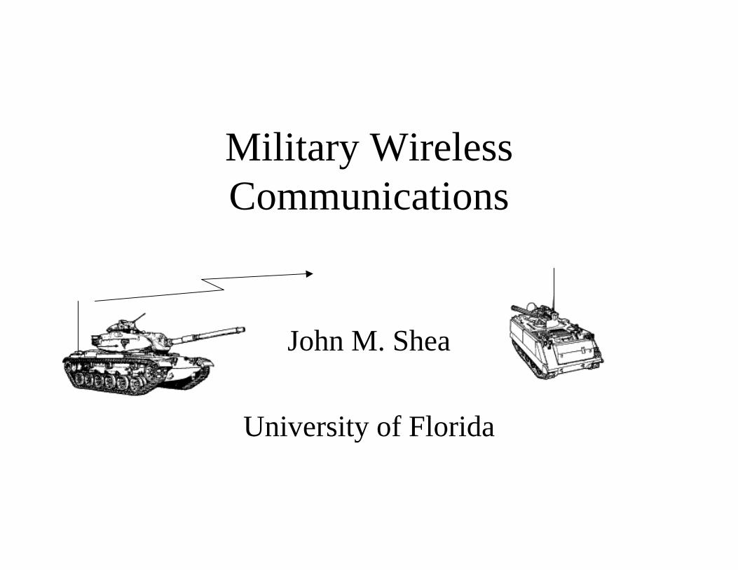
Challenge:Base Stations• Military communications system face many challenges:
– Commercial communication systems can use fixed base stations• The location of these base stations is chosen carefully (usually on a
hill, or in a area without many trees)
• Communication between the base stations uses high-speed fiber-optic, wire, or microwave point-to-point links
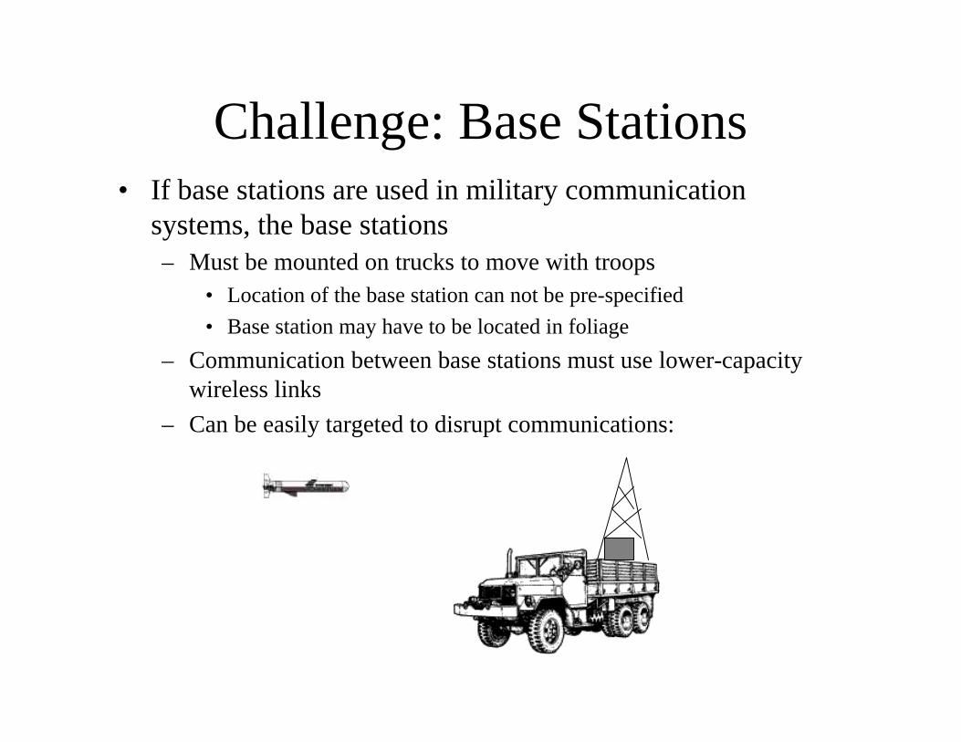
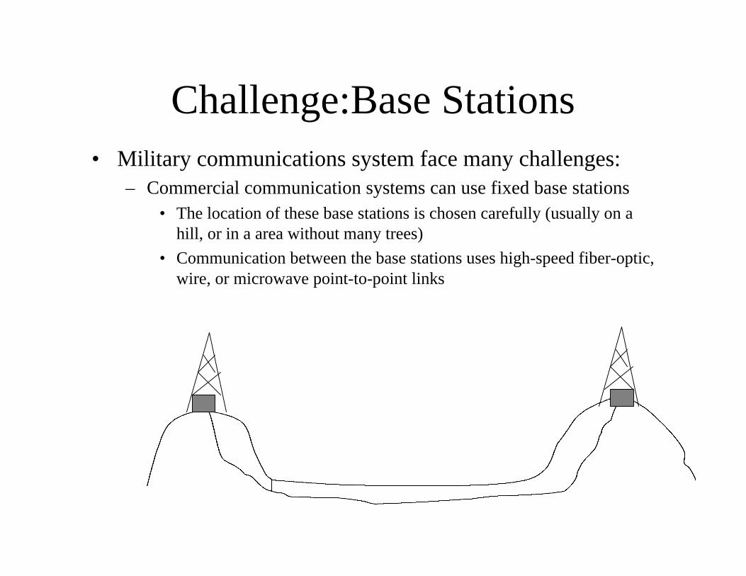
Challenge: Base Stations• If base stations are used in military communication
systems, the base stations – Must be mounted on trucks to move with troops
• Location of the base station can not be pre-specified
• Base station may have to be located in foliage
– Communication between base stations must use lower-capacity wireless links
– Can be easily targeted to disrupt communications:
Alternative to Base Stations:Distributed Radio Networks
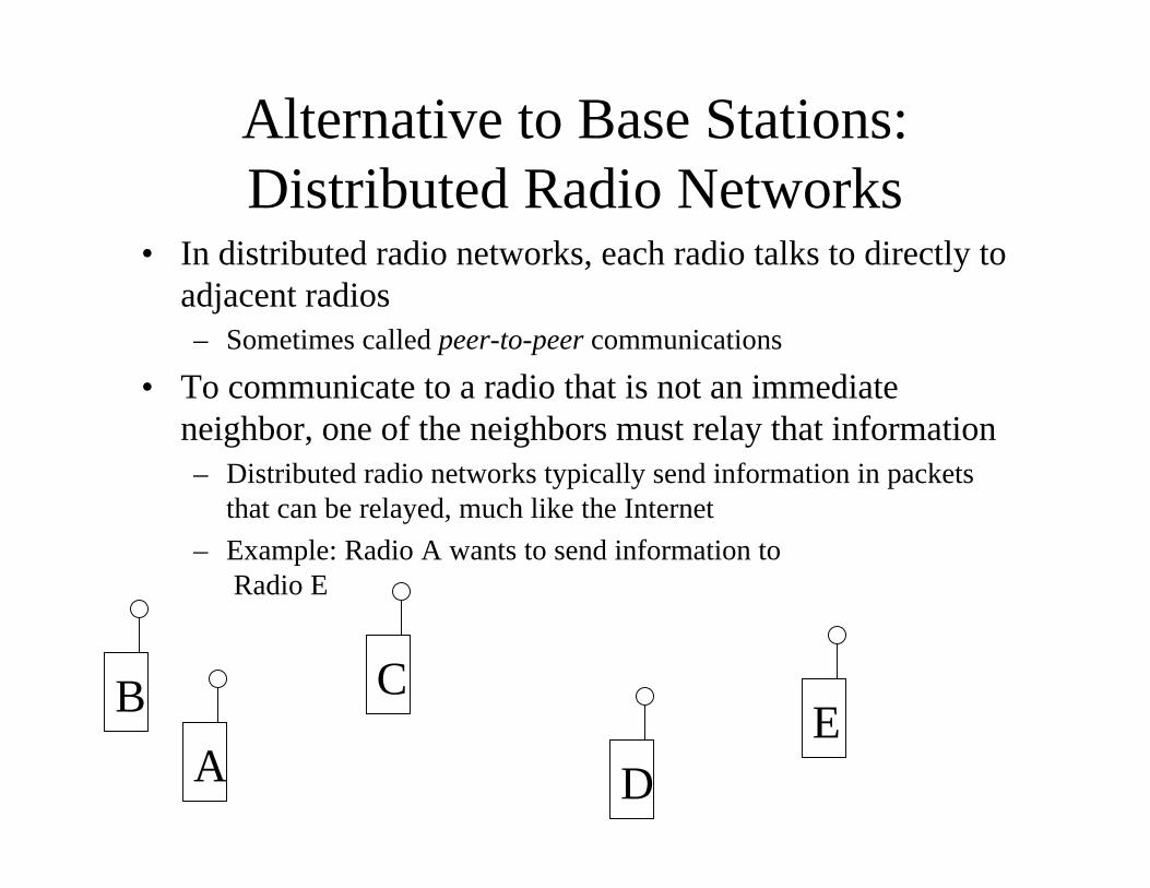
• In distributed radio networks, each radio talks to directly to adjacent radios– Sometimes called peer-to-peer communications
• To communicate to a radio that is not an immediate neighbor, one of the neighbors must relay that information– Distributed radio networks typically send information in packets
that can be relayed, much like the Internet
– Example: Radio A wants to send information toRadio E
A
B C
DE
Distributed Radio Networks
• In distributed radio networks, there is often no centralized control to distribute routing information– The radios don’t automatically know who their
neighbors are or which radio to transmit to in order to relay a packet
– Radios periodically broadcast routing information to neighbors (PROPs)
– The neighbors update their routing tables and later broadcast that info to adjacent radios
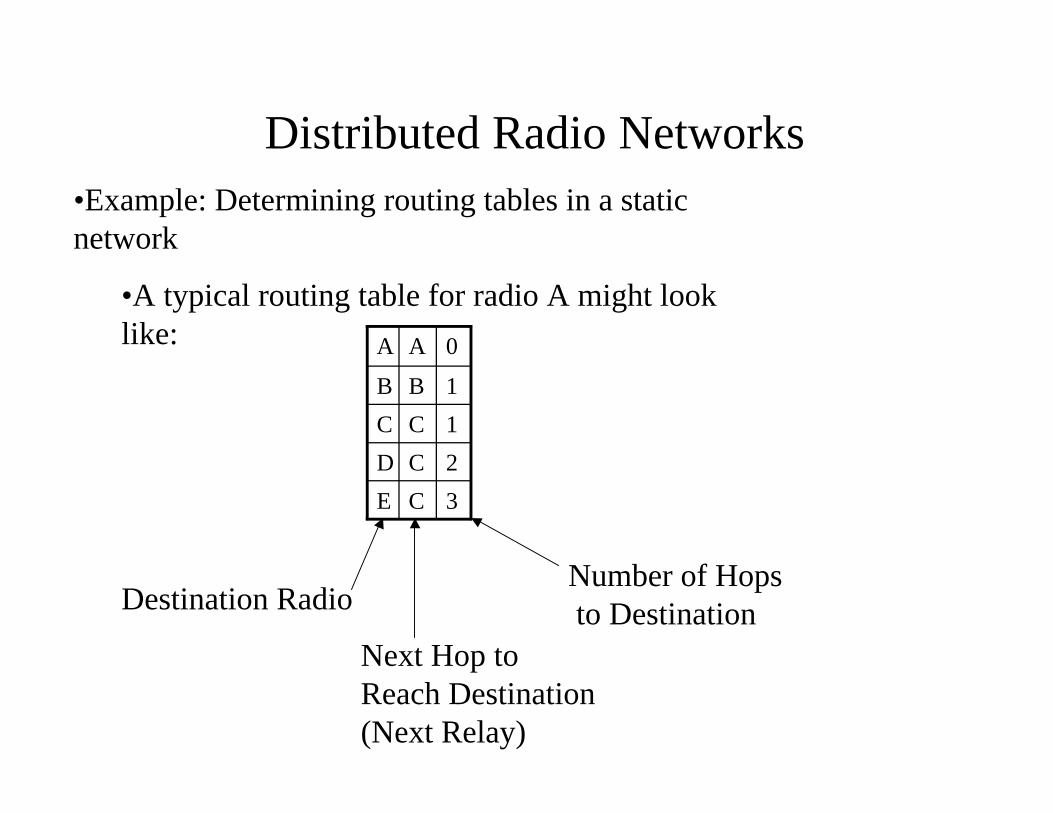
Distributed Radio Networks•Example: Determining routing tables in a static network
•A typical routing table for radio A might look like:
3CE
2CD
1CC
1BB
0AA
Destination Radio
Next Hop to Reach Destination (Next Relay)
Number of Hopsto Destination
Distributed Radio Networks
A
B C
DE
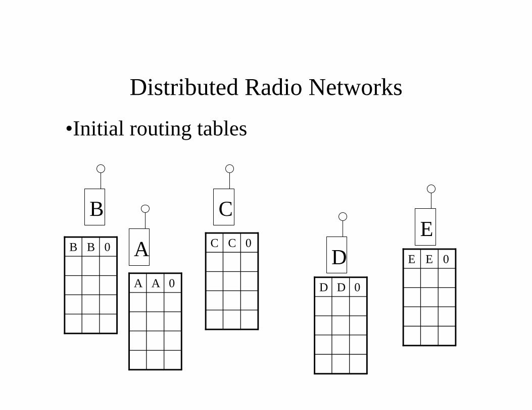
0BB
0AA
0CC
0DD
0EE
•Initial routing tables
Distributed Radio Networks
A
B C
DE
1AA
0BB
0AA
1AA
0CC
0DD
0EE
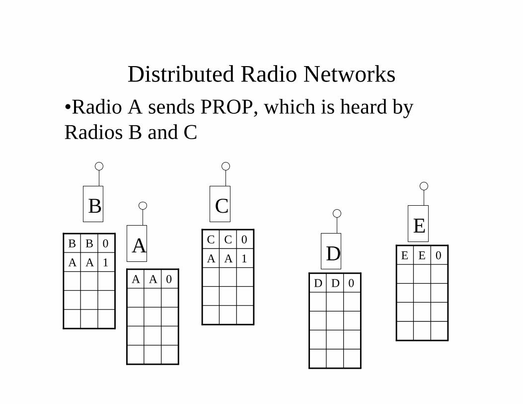
•Radio A sends PROP, which is heard by Radios B and C
Distributed Radio Networks
A
B C
DE
1AA
0BB
1CC
0AA
1AA
0CC
2CA
1CC
0DD
0EE
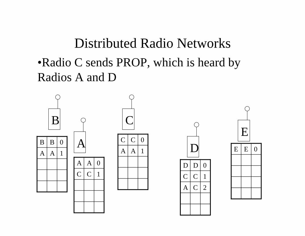
•Radio C sends PROP, which is heard by Radios A and D
Distributed Radio Networks
A
B C
DE
1AA
0BB
1CC
0AA 1DD
1AA
0CC
2CA
1CC
0DD
3DA
2DC
1DD
0EE
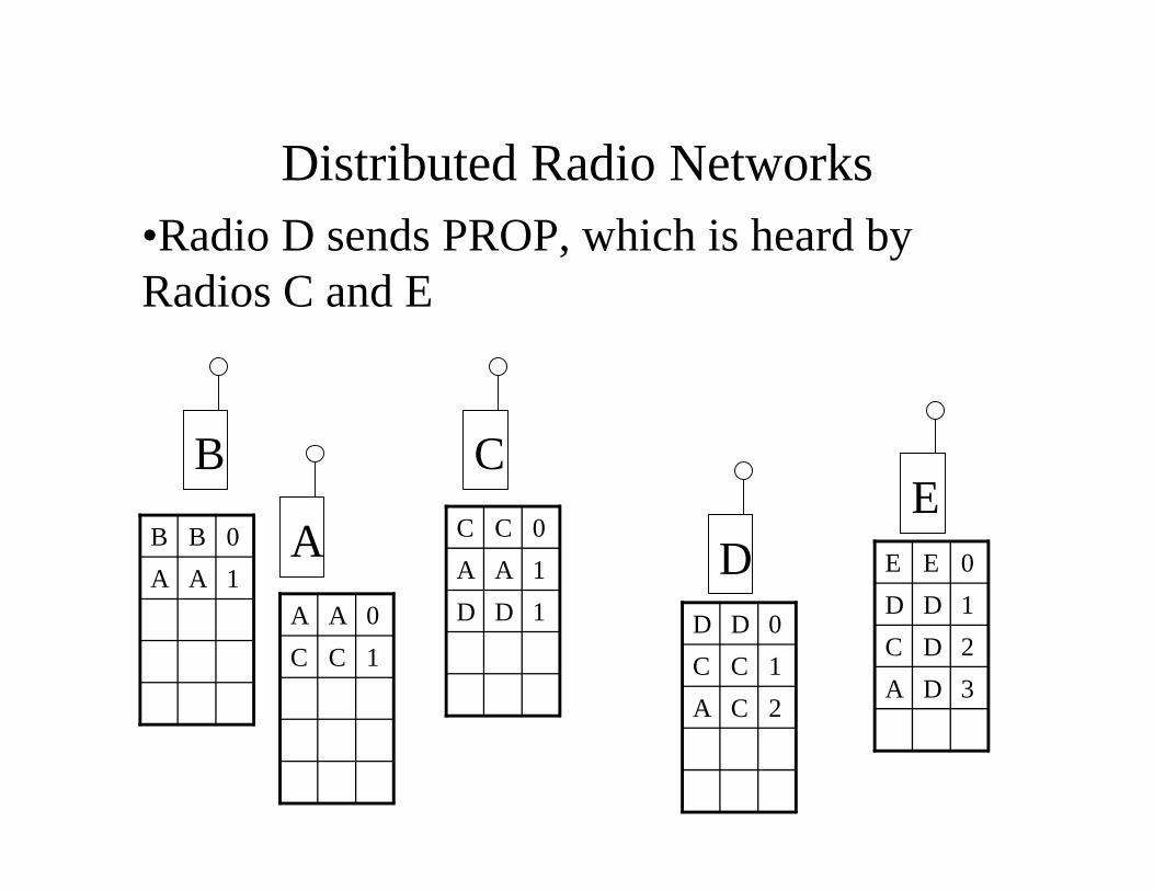
•Radio D sends PROP, which is heard by Radios C and E
Distributed Radio Networks
A
B C
DE
4AE
3AD
2AC
1AA
0BB
3CE
2CD
1BB
1CC
0AA
2DE
2AB
1DD
1AA
0CC
1EE
3CB
2CA
1CC
0DD
4DB
3DA
2DC
1DD
0EE
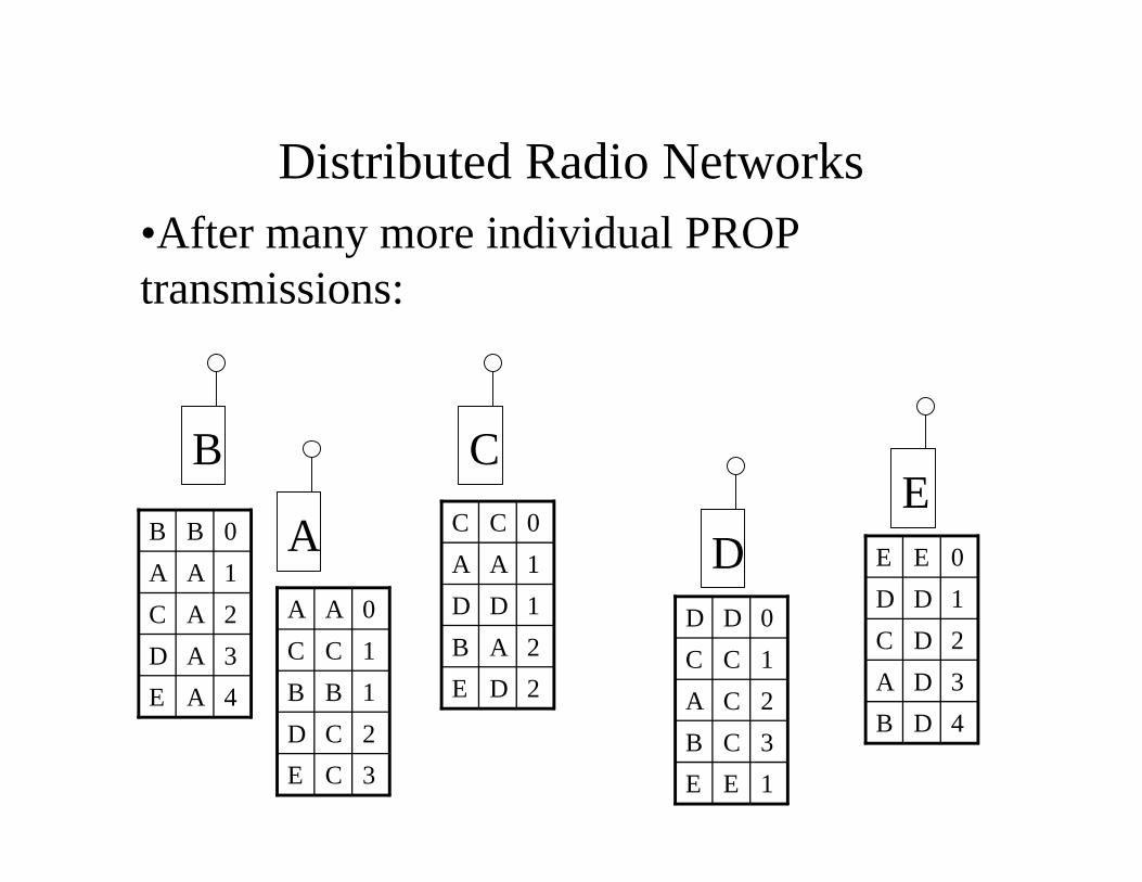
•After many more individual PROP transmissions:
Distributed Radio Networks
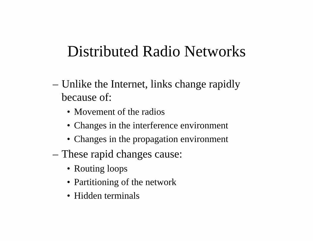
– Unlike the Internet, links change rapidly because of:
• Movement of the radios
• Changes in the interference environment
• Changes in the propagation environment
– These rapid changes cause:• Routing loops
• Partitioning of the network
• Hidden terminals
Challenge: Interception, Detection, & Position-Fixing
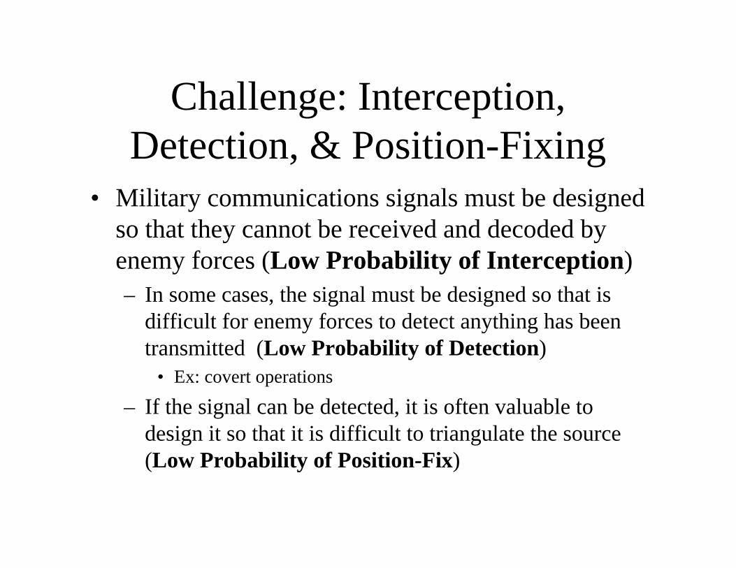
• Military communications signals must be designed so that they cannot be received and decoded by enemy forces (Low Probability of Interception)– In some cases, the signal must be designed so that is
difficult for enemy forces to detect anything has been transmitted (Low Probability of Detection)
• Ex: covert operations
– If the signal can be detected, it is often valuable to design it so that it is difficult to triangulate the source (Low Probability of Position-Fix)
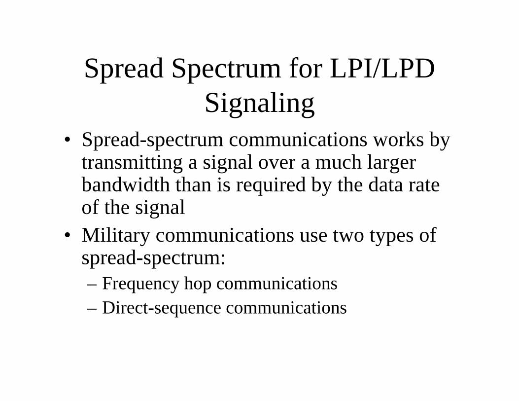
Spread Spectrum for LPI/LPD Signaling
• Spread-spectrum communications works by transmitting a signal over a much larger bandwidth than is required by the data rate of the signal
• Military communications use two types of spread-spectrum:– Frequency hop communications– Direct-sequence communications
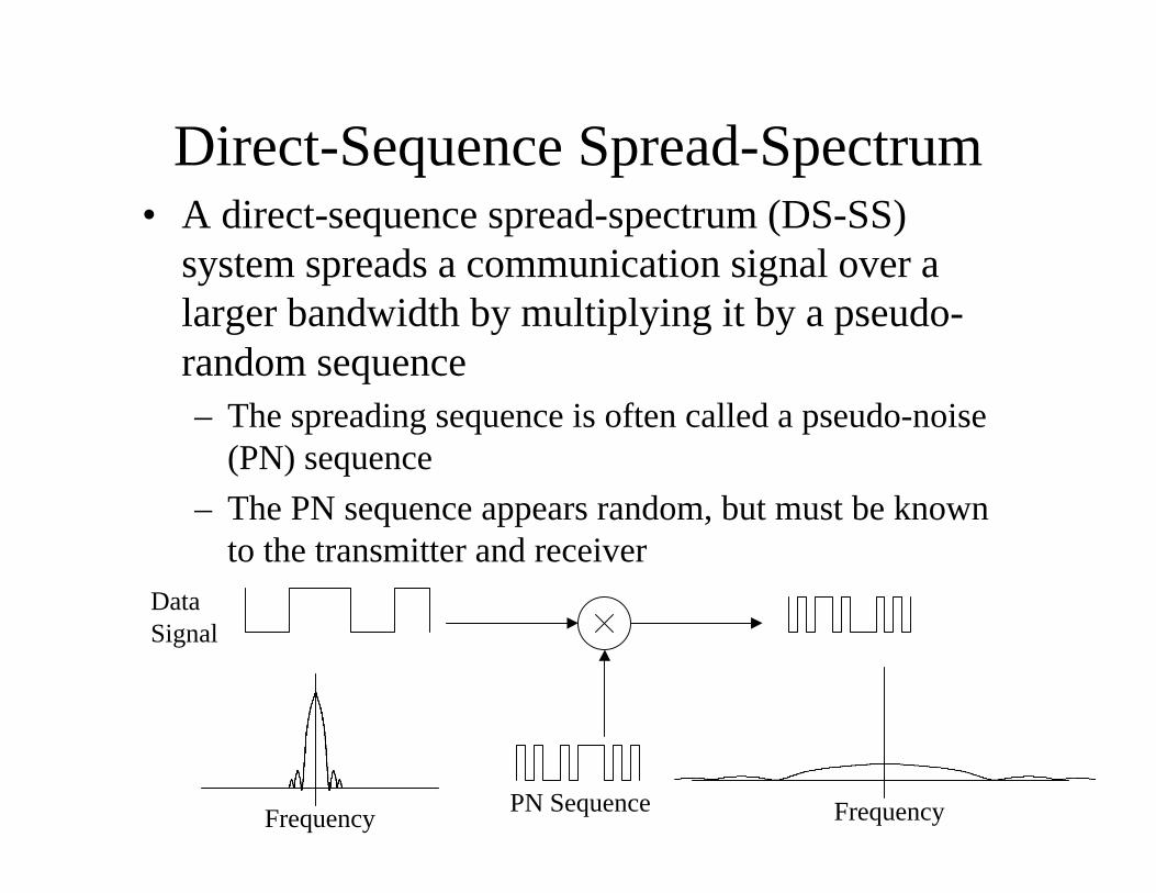
Direct-Sequence Spread-Spectrum• A direct-sequence spread-spectrum (DS-SS)
system spreads a communication signal over a larger bandwidth by multiplying it by a pseudo-random sequence– The spreading sequence is often called a pseudo-noise
(PN) sequence
– The PN sequence appears random, but must be known to the transmitter and receiver
Data Signal
PN SequenceFrequency Frequency

Direct-Sequence Spread-Spectrum• A DS-SS signal offers low-probability of
detection by reducing the amount of energy in any frequency band:
• A DS-SS signal provides low-probability of interception, because the data cannot be recovered without knowing the PN sequence:
Frequency Frequency
Narrowband Signal
DS-SS Signal
PN Sequence
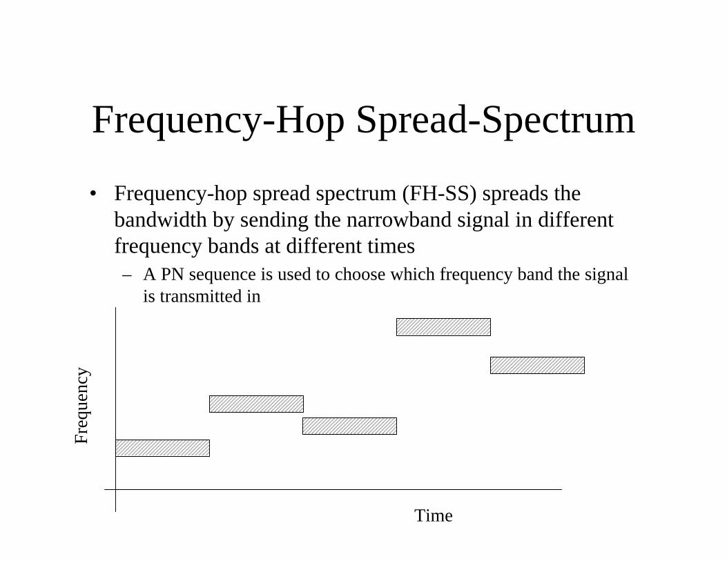
Frequency-Hop Spread-Spectrum
• Frequency-hop spread spectrum (FH-SS) spreads the bandwidth by sending the narrowband signal in different frequency bands at different times– A PN sequence is used to choose which frequency band the signal
is transmitted in
Freq
uenc
y
Time
Frequency-Hop Spread-Spectrum
• FH-SS does not provide the same low probability of detection as DS-SS, because the signal is still concentrated in a small bandwidth
• However, FH-SS does increase the monitoring requirement for a hostile agent to detect the signal
• FH-SS provides similar low probability of interception to DS-SS, because any hostile agent must know the hopping pattern to recover the data
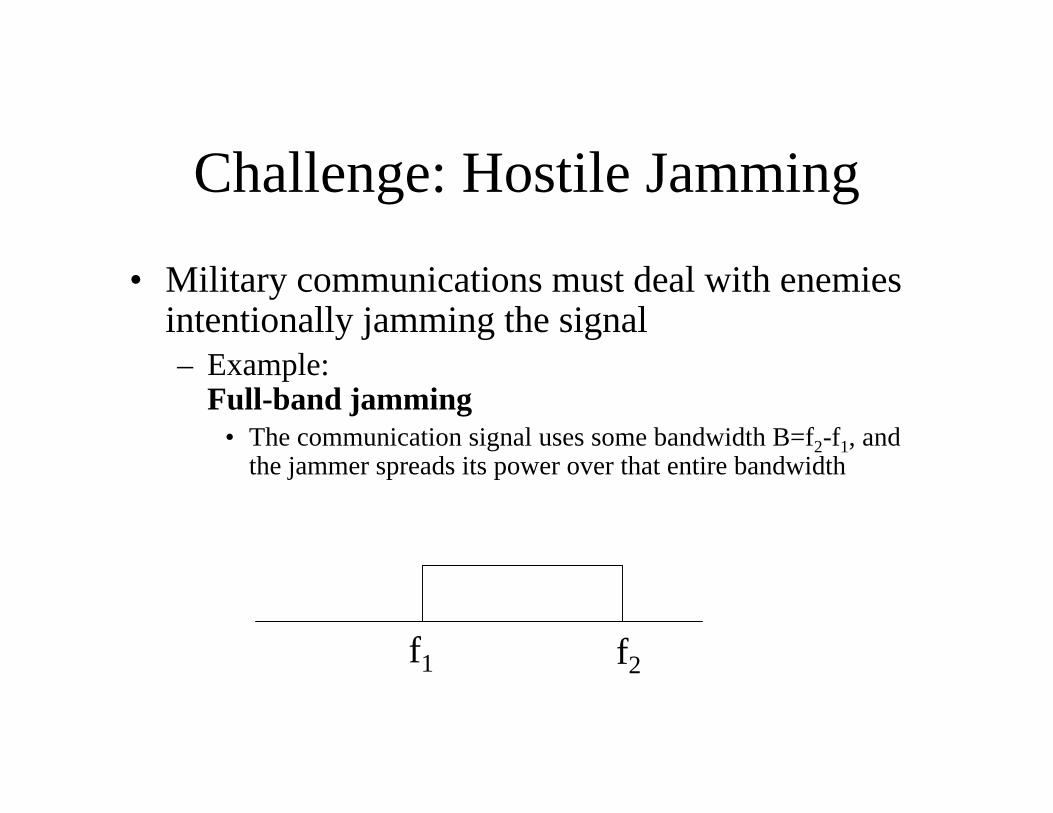
Challenge: Hostile Jamming
• Military communications must deal with enemies intentionally jamming the signal– Example:
Full-band jamming• The communication signal uses some bandwidth B=f2-f1, and
the jammer spreads its power over that entire bandwidth
f2f1
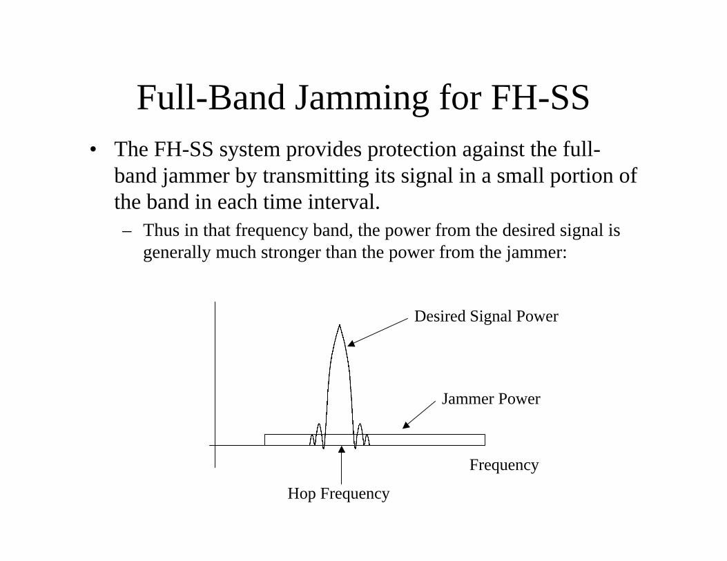
Full-Band Jamming for FH-SS• The FH-SS system provides protection against the full-
band jammer by transmitting its signal in a small portion of the band in each time interval.– Thus in that frequency band, the power from the desired signal is
generally much stronger than the power from the jammer:
Frequency
Hop Frequency
Desired Signal Power
Jammer Power
Challenge: Hostile Jamming
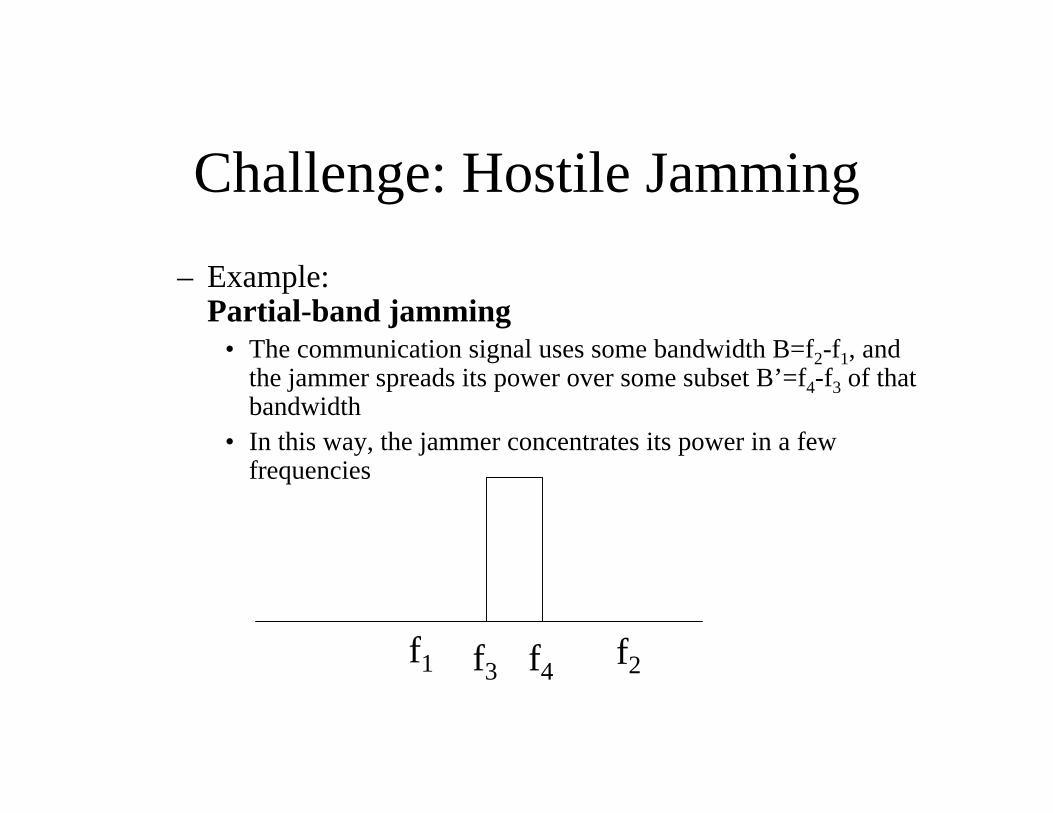
– Example:Partial-band jamming
• The communication signal uses some bandwidth B=f2-f1, and the jammer spreads its power over some subset B’=f4-f3 of that bandwidth
• In this way, the jammer concentrates its power in a few frequencies
f2f1 f4f3
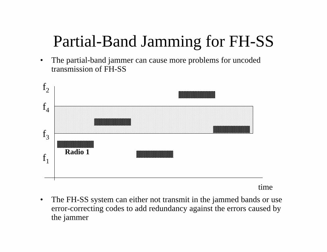
Partial-Band Jamming for FH-SS• The partial-band jammer can cause more problems for uncoded
transmission of FH-SS
• The FH-SS system can either not transmit in the jammed bands or use error-correcting codes to add redundancy against the errors caused by the jammer
f2
f1
time
Radio 1
f4
f3
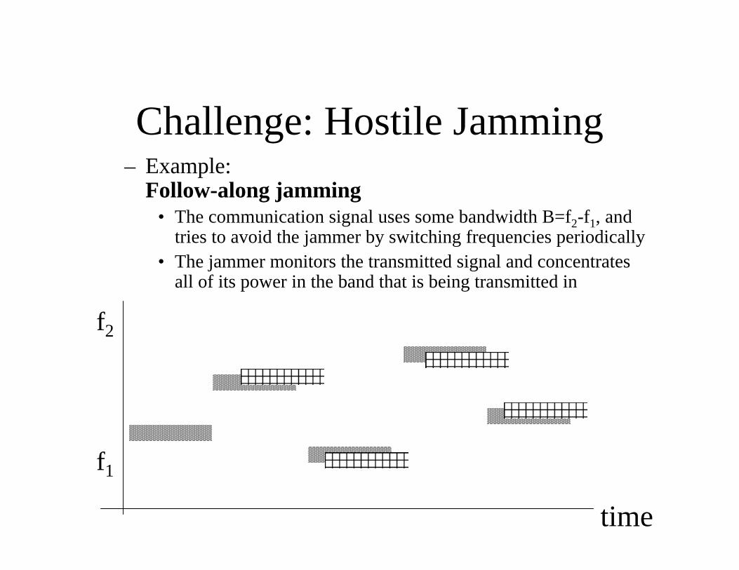
Challenge: Hostile Jamming– Example:
Follow-along jamming• The communication signal uses some bandwidth B=f2-f1, and
tries to avoid the jammer by switching frequencies periodically • The jammer monitors the transmitted signal and concentrates
all of its power in the band that is being transmitted in
f2
f1
time
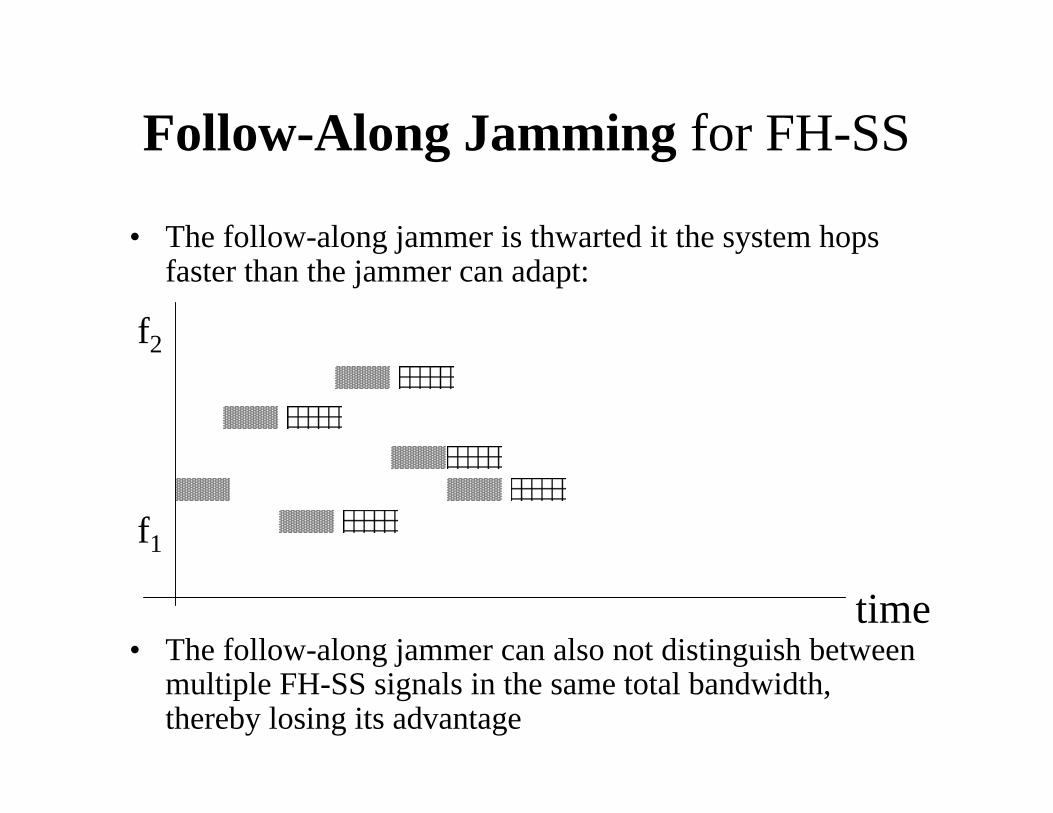
Follow-Along Jamming for FH-SS
• The follow-along jammer is thwarted it the system hops faster than the jammer can adapt:
• The follow-along jammer can also not distinguish between multiple FH-SS signals in the same total bandwidth, thereby losing its advantage
f2
f1
time
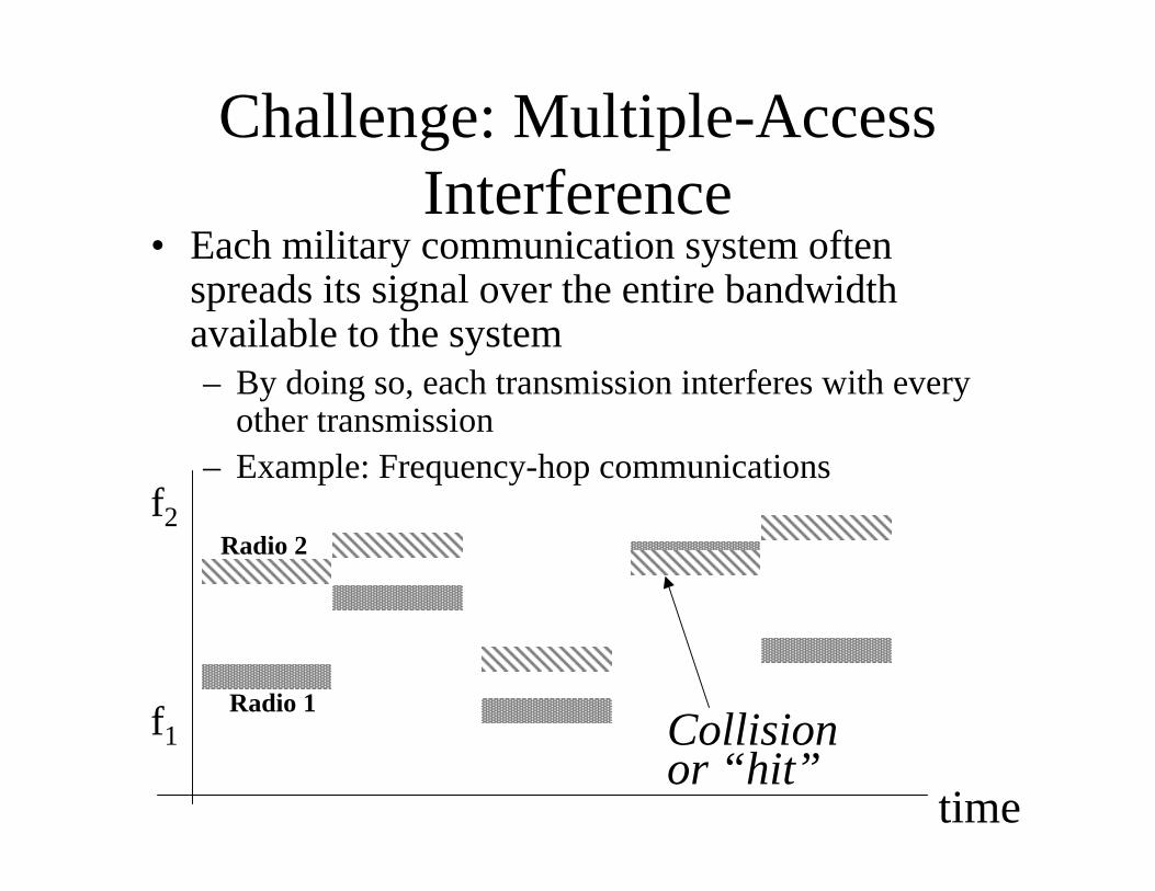
Challenge: Multiple-Access Interference
• Each military communication system often spreads its signal over the entire bandwidth available to the system– By doing so, each transmission interferes with every
other transmission– Example: Frequency-hop communications
f2
f1
time
Collisionor “hit”
Radio 1
Radio 2
Multiple-Access Interference for FH-SS
• Solution for FH-SS is generally to use error-correcting codes that can tolerate some collisions– The code symbols are interleaved so that the
symbols in a dwell come from different codewords – that way some of each codeword’s symbols are not “hit”
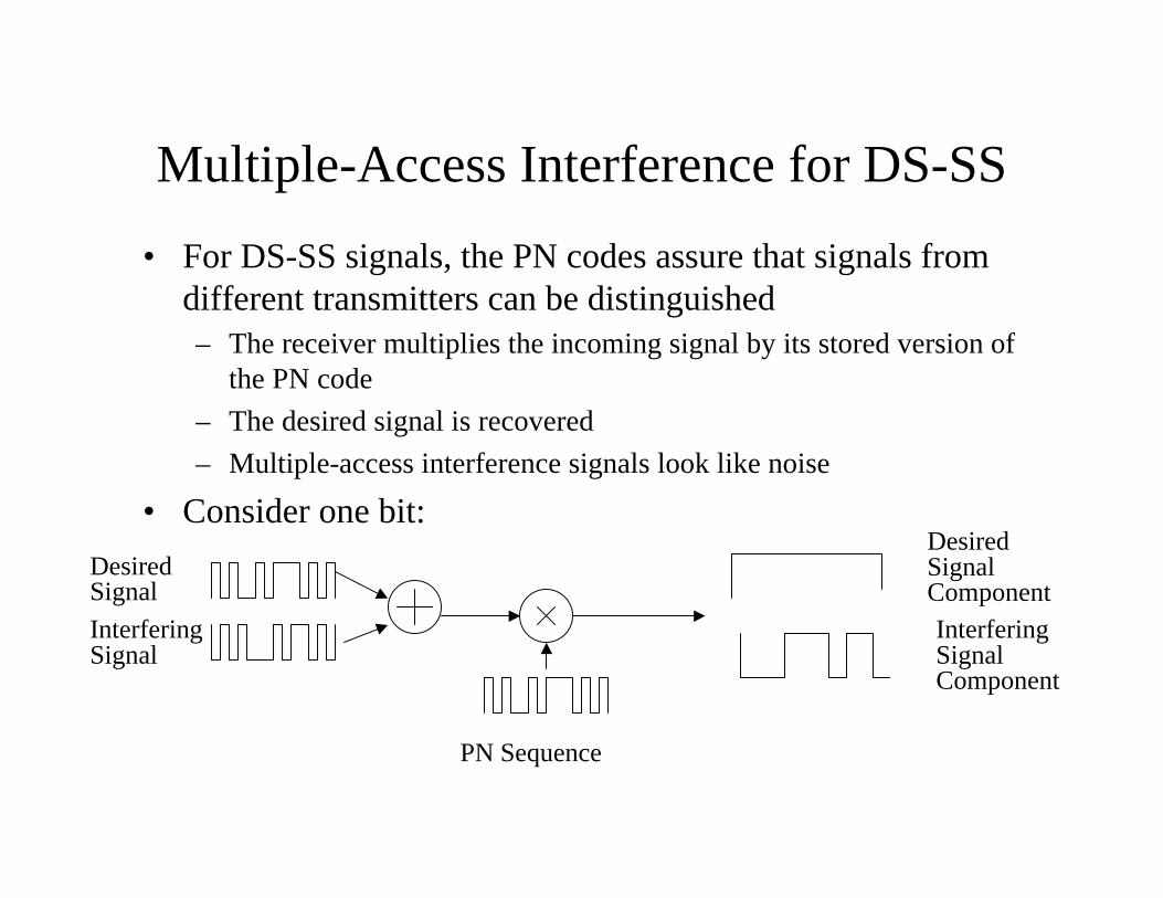
Multiple-Access Interference for DS-SS
• For DS-SS signals, the PN codes assure that signals from different transmitters can be distinguished– The receiver multiplies the incoming signal by its stored version of
the PN code
– The desired signal is recovered
– Multiple-access interference signals look like noise
• Consider one bit:
Desired Signal
PN Sequence
Interfering Signal
Desired SignalComponent
Interfering SignalComponent