Embed Size (px)
DESCRIPTION
Manual for military scuba diving
Citation preview
FM 20-11C1
Change 1 HeadquartersDepartment of the Army
Washington, DC, 14 April 2000
Militar y Divin g1. Change FM 20-11, 20 January 1999, as follows:
Remove Old Pages Insert New Pages
A and B A through Diii through vi iii through vixxi and xxii xxi and xxiixli through xliv xli through xlivliii and liv liii and livlvii and lviii lvii and lviii2-23 and 2-24 2-23 and 2-243-11 and 3-12 3-11 and 3-124-7 through 4-10 4-7 through 4-105-1 and 5-2 5-1 and 5-21A-3 and 1A-4 1A-3 and 1A-41A-7 through 1A-12 1A-7 through 1A-121C-1 and 1C-2 1C-1 and 1C-22-v and 2-vi 2-v and 2-vi2-xvii and 2-xviii 2-xvii and 2-xviii6-21 and 6-22 6-21 and 6-227-3 and 7-4 7-3 and 7-48-1 through 8-12 8-1 through 8-128-15 and 8-16 8-15 and 8-169-3 and 9-4 9-3 and 9-49-63 through 9-66 9-63 through 9-6610-7 through 10-12 10-7 through 10-1213-1 and 13-2 13-1 and 13-214-1 and 14-2 14-1 and 14-215-19 and 15-20 15-19 and 15-2015-33 and 15-34 15-33 and 15-3417-1 and 17-2 17-1 and 17-217-9 and 17-10 17-9 and 17-1017-15 and 17-16 17-15 and 17-1617-21 through 17-24 17-21 through 17-2418-13 through 18-16 18-13 through 18-165-v through 5-viii 5-v through 5-viii5-xi and 5-xii 5-xi and 5-xii21-13 and 21-14 21-13 and 21-14

21-17 and 21-18 21-17 and 21-1821-23 and 21-24 21-23 and 21-2421-35 through 21-38 21-35 through 21-3822-11 through 22-14 22-11 through 22-1422-25 and 22-26 22-25 and 22-26
2. A bar (❚) marks new or changed material.
3. File this transmittal sheet in front of the publication.
DISTRIBUTION RESTRICTION: Approved for public release; distribution is unlimited.
By Order of the Secretary of the Army:
ERIC K. SHINSEKIGeneral, United States Army
Chief of Staff
Official:
DISTRIBUTION:
Active Army and US Army Reserve: To be distributed in accordance with the initial distribution number 115782 requirements for FM 20-11.
Army National Guard: None.
JOEL B. HUDSONAdministrative Assistant to the
Secretary of the Army0005603

SS521-AG-PRO-010 Change 1
*Zero in this column indicates an original page.
List of Effective Pages A
LIST OF EFFECTIVE PAGES
Date of issue for original is:
Original . . . . . . . . . . . . . . . . . . . . . . . . . . . . . . . . . . . . . . . . . . . . . . . . . . 20 January 1999
TOTAL NUMBER OF PAGES IN THIS PUBLICATION IS 950, CONSISTING OF THE FOLLOWING:
Title Page . . . . . . . . . . . . . . . . . . . . . . . . 0Title Page-2 blank. . . . . . . . . . . . . . . . . . 0A through C . . . . . . . . . . . . . . . . . . . . . . 1D blank . . . . . . . . . . . . . . . . . . . . . . . . . . 1Certification Sheet . . . . . . . . . . . . . . . . . 0Certification Sheet-2 blank . . . . . . . . . . . 0Record of Changes. . . . . . . . . . . . . . . . . 0Record of Changes-2 blank . . . . . . . . . . 0i (Foreword) . . . . . . . . . . . . . . . . . . . . . . 0ii blank . . . . . . . . . . . . . . . . . . . . . . . . . . 0iii . . . . . . . . . . . . . . . . . . . . . . . . . . . . . . . 0iv through v . . . . . . . . . . . . . . . . . . . . . . . 1vi through xx . . . . . . . . . . . . . . . . . . . . . . 0xxi . . . . . . . . . . . . . . . . . . . . . . . . . . . . . . 1xxii through xli. . . . . . . . . . . . . . . . . . . . . 0xlii . . . . . . . . . . . . . . . . . . . . . . . . . . . . . . 1xliii. . . . . . . . . . . . . . . . . . . . . . . . . . . . . . 0xliv . . . . . . . . . . . . . . . . . . . . . . . . . . . . . 1xlv through liii . . . . . . . . . . . . . . . . . . . . . 0liv . . . . . . . . . . . . . . . . . . . . . . . . . . . . . . 1lv . . . . . . . . . . . . . . . . . . . . . . . . . . . . . . . 0lvi blank. . . . . . . . . . . . . . . . . . . . . . . . . . 0lvii . . . . . . . . . . . . . . . . . . . . . . . . . . . . . . 0lviii. . . . . . . . . . . . . . . . . . . . . . . . . . . . . . 1lix . . . . . . . . . . . . . . . . . . . . . . . . . . . . . . 0lx blank . . . . . . . . . . . . . . . . . . . . . . . . . . 0Vol. 1 Title Page . . . . . . . . . . . . . . . . . . . 0Vol.1 Title Page-2 blank . . . . . . . . . . . . . 01-i through 1-x . . . . . . . . . . . . . . . . . . . . 01-xi through 1-xii . . . . . . . . . . . . . . . . . . . 01-xiii . . . . . . . . . . . . . . . . . . . . . . . . . . . . 0
1-xiv blank . . . . . . . . . . . . . . . . . . . . . . . .01-1 through 1-31 . . . . . . . . . . . . . . . . . . .01-32 blank . . . . . . . . . . . . . . . . . . . . . . . .02-1 through 2-23 . . . . . . . . . . . . . . . . . . .02-24 . . . . . . . . . . . . . . . . . . . . . . . . . . . . .12-25 through 2-36 . . . . . . . . . . . . . . . . . .03-1 through 3-11 . . . . . . . . . . . . . . . . . . .03-12 . . . . . . . . . . . . . . . . . . . . . . . . . . . . .13-13 through 3-53 . . . . . . . . . . . . . . . . . .03-54 blank . . . . . . . . . . . . . . . . . . . . . . . .04-1 through 4-7 . . . . . . . . . . . . . . . . . . . .04-8 through 4-9 . . . . . . . . . . . . . . . . . . . .14-10 through 4-13 . . . . . . . . . . . . . . . . . .04-14 blank . . . . . . . . . . . . . . . . . . . . . . . .05-1 . . . . . . . . . . . . . . . . . . . . . . . . . . . . . .05-2 . . . . . . . . . . . . . . . . . . . . . . . . . . . . . .15-3 through 5-13 . . . . . . . . . . . . . . . . . . .01A-1 through 1A-3 . . . . . . . . . . . . . . . . . .01A-4 . . . . . . . . . . . . . . . . . . . . . . . . . . . . .11A-5 through 1A-7 . . . . . . . . . . . . . . . . . .01A-8 through 1A-11 . . . . . . . . . . . . . . . . .11A-12 through 1A-16 . . . . . . . . . . . . . . . .01B-1 through 1B-3 . . . . . . . . . . . . . . . . . .01B-4 blank . . . . . . . . . . . . . . . . . . . . . . . .01C-1. . . . . . . . . . . . . . . . . . . . . . . . . . . . .11C-2 blank . . . . . . . . . . . . . . . . . . . . . . . .01D-1 through 1D-10. . . . . . . . . . . . . . . . .0Index 1-1 through Index 1-7 . . . . . . . . . .0Index 1-8 blank . . . . . . . . . . . . . . . . . . . .0Vol. 2 Title Page. . . . . . . . . . . . . . . . . . . .0Vol. 2 Title Page-2 blank . . . . . . . . . . . . .0
Page No. *Change No. Page No. *Change No.

Change 1
*Zero in this column indicates an original page.
B List of Effective Pages
Page No. *Change No. Page No. *Change No.2-i through 2-v . . . . . . . . . . . . . . . . . . . . . 02vi . . . . . . . . . . . . . . . . . . . . . . . . . . . . . . 12-vii through 2-xv. . . . . . . . . . . . . . . . . . . 02-xvi blank . . . . . . . . . . . . . . . . . . . . . . . . 02-xvii . . . . . . . . . . . . . . . . . . . . . . . . . . . . 12-xviii blank . . . . . . . . . . . . . . . . . . . . . . . 06-1 through 6-20 . . . . . . . . . . . . . . . . . . . 06-21 . . . . . . . . . . . . . . . . . . . . . . . . . . . . . 16-22 through 6-54 . . . . . . . . . . . . . . . . . . 07-1 through 7-3 . . . . . . . . . . . . . . . . . . . . 07-4 . . . . . . . . . . . . . . . . . . . . . . . . . . . . . . 17-5 through 7-41 . . . . . . . . . . . . . . . . . . . 07-42 blank . . . . . . . . . . . . . . . . . . . . . . . . 08-1 through 8-4 . . . . . . . . . . . . . . . . . . . . 18-5 . . . . . . . . . . . . . . . . . . . . . . . . . . . . . . 08-6 through 8-7 . . . . . . . . . . . . . . . . . . . . 18-8 . . . . . . . . . . . . . . . . . . . . . . . . . . . . . . 08-9 . . . . . . . . . . . . . . . . . . . . . . . . . . . . . . 18-10 through 8-11 . . . . . . . . . . . . . . . . . . 08-12 . . . . . . . . . . . . . . . . . . . . . . . . . . . . . 18-13 through 8-14 . . . . . . . . . . . . . . . . . . 08-15 through 8-16 . . . . . . . . . . . . . . . . . . 18-17 through 8-34 . . . . . . . . . . . . . . . . . . 09-1 through 9-2 . . . . . . . . . . . . . . . . . . . . 09-3 . . . . . . . . . . . . . . . . . . . . . . . . . . . . . . 19-4 through 9-63 . . . . . . . . . . . . . . . . . . . 09-64 through 9-66 . . . . . . . . . . . . . . . . . . 19-67 through 9-70 . . . . . . . . . . . . . . . . . . 010-1 through 10-7 . . . . . . . . . . . . . . . . . . 010-8 through 10-9 . . . . . . . . . . . . . . . . . . 110-10 . . . . . . . . . . . . . . . . . . . . . . . . . . . . 010-11 . . . . . . . . . . . . . . . . . . . . . . . . . . . . 110-12 through 10-13 . . . . . . . . . . . . . . . . 010-14 blank . . . . . . . . . . . . . . . . . . . . . . . 011-1 through 11-14 . . . . . . . . . . . . . . . . . 0Index 2-1 through Index 2-6 . . . . . . . . . . 0Vol. 3 Title Page . . . . . . . . . . . . . . . . . . . 0Vol. 3 Title Page-2 blank . . . . . . . . . . . . . 03-i through 3-vii . . . . . . . . . . . . . . . . . . . . 03-viii blank . . . . . . . . . . . . . . . . . . . . . . . . 03-ix. . . . . . . . . . . . . . . . . . . . . . . . . . . . . . 03-x blank . . . . . . . . . . . . . . . . . . . . . . . . . 0
3-xi . . . . . . . . . . . . . . . . . . . . . . . . . . . . . 03-xii blank . . . . . . . . . . . . . . . . . . . . . . . . 012-1 through 12-14. . . . . . . . . . . . . . . . . 013-1 . . . . . . . . . . . . . . . . . . . . . . . . . . . . 013-2 . . . . . . . . . . . . . . . . . . . . . . . . . . . . 113-3 through 13-14. . . . . . . . . . . . . . . . . 014-1 . . . . . . . . . . . . . . . . . . . . . . . . . . . . 014-2 . . . . . . . . . . . . . . . . . . . . . . . . . . . . 114-3 through 14-36. . . . . . . . . . . . . . . . . 015-1 through 15-18. . . . . . . . . . . . . . . . . 015-19 . . . . . . . . . . . . . . . . . . . . . . . . . . . 115-20 through 15-33. . . . . . . . . . . . . . . . 015-34 . . . . . . . . . . . . . . . . . . . . . . . . . . . 115-35 through 15-39. . . . . . . . . . . . . . . . 015-40 blank. . . . . . . . . . . . . . . . . . . . . . . 016-1 through 16-9. . . . . . . . . . . . . . . . . . 016-10 blank. . . . . . . . . . . . . . . . . . . . . . . 0Index 3-1 through Index 3-3 . . . . . . . . . . 0Index 3-4 blank. . . . . . . . . . . . . . . . . . . . 0Vol. 4 Title Page . . . . . . . . . . . . . . . . . . . 0Vol. 4 Title Page-2 blank. . . . . . . . . . . . . 04i through 4-v . . . . . . . . . . . . . . . . . . . . . 04-vi blank . . . . . . . . . . . . . . . . . . . . . . . . 04-vii . . . . . . . . . . . . . . . . . . . . . . . . . . . . . 04-viii blank . . . . . . . . . . . . . . . . . . . . . . . 04-ix . . . . . . . . . . . . . . . . . . . . . . . . . . . . . 04-x blank. . . . . . . . . . . . . . . . . . . . . . . . . 017-1 . . . . . . . . . . . . . . . . . . . . . . . . . . . . 117-2 through 17-8. . . . . . . . . . . . . . . . . . 017-9 through 17-10. . . . . . . . . . . . . . . . . 117-11 through 17-14 . . . . . . . . . . . . . . . . 017-15 . . . . . . . . . . . . . . . . . . . . . . . . . . . 117-16 through 17-20. . . . . . . . . . . . . . . . 017-21 . . . . . . . . . . . . . . . . . . . . . . . . . . . 117-22 . . . . . . . . . . . . . . . . . . . . . . . . . . . 017-23 . . . . . . . . . . . . . . . . . . . . . . . . . . . 117-24 through 17-63. . . . . . . . . . . . . . . . 017-64 blank. . . . . . . . . . . . . . . . . . . . . . . 018-1 through 18-12. . . . . . . . . . . . . . . . . 018-13 through 18-16. . . . . . . . . . . . . . . . 118-17 through 18-27. . . . . . . . . . . . . . . . 018-28 blank. . . . . . . . . . . . . . . . . . . . . . . 0

Change 1
*Zero in this column indicates an original page.
List of Effective Pages C
Page No. *Change No. Page No. *Change No.Index 4-1 through Index 4-2 . . . . . . . . . . 0Vol. 5 Title Page . . . . . . . . . . . . . . . . . . . 0Vol. 5 Title Page-2 blank. . . . . . . . . . . . . 05-i through 5-iv . . . . . . . . . . . . . . . . . . . . 05-v through 5-vii . . . . . . . . . . . . . . . . . . . 15-viii through 5-x . . . . . . . . . . . . . . . . . . . 05-xi . . . . . . . . . . . . . . . . . . . . . . . . . . . . . 15-xii through 5-xiii . . . . . . . . . . . . . . . . . . 05-xiv blank . . . . . . . . . . . . . . . . . . . . . . . 019-1 through 19-18. . . . . . . . . . . . . . . . . 020-1 through 20-8. . . . . . . . . . . . . . . . . . 021-1 through 21-13. . . . . . . . . . . . . . . . . 021-14 . . . . . . . . . . . . . . . . . . . . . . . . . . . 121-15 through 21-17. . . . . . . . . . . . . . . . 021-18 . . . . . . . . . . . . . . . . . . . . . . . . . . . 121-19 through 21-22. . . . . . . . . . . . . . . . 021-23 . . . . . . . . . . . . . . . . . . . . . . . . . . . 121-24 through 21-35. . . . . . . . . . . . . . . . 021-36 . . . . . . . . . . . . . . . . . . . . . . . . . . . 1
21-37 . . . . . . . . . . . . . . . . . . . . . . . . . . . .021-38 . . . . . . . . . . . . . . . . . . . . . . . . . . . .121-39 through 21-49 . . . . . . . . . . . . . . . .021-50 blank . . . . . . . . . . . . . . . . . . . . . . .022-1 through 22-10 . . . . . . . . . . . . . . . . .022-11 through 21-12 . . . . . . . . . . . . . . . .122-13 . . . . . . . . . . . . . . . . . . . . . . . . . . . .022-14 . . . . . . . . . . . . . . . . . . . . . . . . . . . .122-15 through 22-25 . . . . . . . . . . . . . . . .022-26 . . . . . . . . . . . . . . . . . . . . . . . . . . . .15A-1 through 5A-13 . . . . . . . . . . . . . . . . .05A-14 blank . . . . . . . . . . . . . . . . . . . . . . .05B-1 through 5B-7 . . . . . . . . . . . . . . . . . .05B-8 blank . . . . . . . . . . . . . . . . . . . . . . . .05C-1 through 5C-23. . . . . . . . . . . . . . . . .05C-24 blank . . . . . . . . . . . . . . . . . . . . . . .0Index 5-1 through Index 5-4 . . . . . . . . . .0Index-1 through Index-16 . . . . . . . . . . . .0

Change 1
D List of Effective Pages
Page Left Blank Intentionally

Safety Summary iii
6DIHW\�6XPPDU\
STANDARD NAVY SYNTAX
Since this manual will form the technical basis of many subsequent instructions or directives,it utilizes the standard Navy syntax as pertains to permissive, advisory, and mandatorylanguage. This is done to facilitate the use of the information provided herein as a referencefor issuing Fleet Directives. The concept of word usage and intended meaning that has beenadhered to in preparing this manual is as follows:
“Shall” has been used only when application of a procedure is mandatory.
“Should” has been used only when application of a procedure is recommended.
“May” and “need not” have been used only when application of a procedure is discretionary.
“Will” has been used only to indicate futurity; never to indicate any degree of requirement forapplication of a procedure.
The usage of other words has been checked against other standard nautical and naval termi-nology references.
GENERAL SAFETY
This Safety Summary contains all specific WARNINGS and CAUTIONS appearing else-where in this manual and are referenced by page number. Should situations arise that are notcovered by the general and specific safety precautions, the Commanding Officer or otherauthority will issue orders, as deemed necessary, to cover the situation.
SAFETY GUIDELINES
Extensive guidance for safety can be found in the OPNAV 5100 series instruction manual,Navy Safety Precautions.
SAFETY PRECAUTIONS
The WARNINGS, CAUTIONS, and NOTES contained in this manual are defined as follows:
WARNING Identifies an operatin g or maintenance procedure, practice, condition, orstatement, which, if not strictly observed, could result in injury to ordeath of personnel.
CAUTION Identifies an operatin g or maintenance procedure, practice, condition, orstatement, which, if not strictly observed, could result in dama ge to ordestruction of equipment or loss of mission effectiveness, or lon g-termhealth hazard to personnel.
NOTE An essential operatin g or maintenance procedure, condition, orstatement, which must be hi ghli ghted.

iv U.S. Navy Diving Manual
WARNING Hyperventilation is dan gerous and can lead to unconsciousness anddeath. (Pa ge 3-20)
WARNING Never do a forceful Valsalva maneuver durin g descent or ascent. Durin gdescent, this action can result in alternobaric verti go or a round or ovalwindow rupture. Durin g ascent, this action can result in a pulmonaryoverinflation syndrome. (Pa ge 3-23)
WARNING Do not use a malfunctionin g compressor to pump diver’s breathin g airor char ge diver's air stora ge flasks as this may result in contaminationof the diver's air supply. (Pa ge 4-11)
WARNING Weldin g or cuttin g torches may cause an explosion on penetration ofgas-filled compartments, resultin g in serious injury or death. (Pa ge 6-19)
WARNING Scuba equipment is not authorized for use in enclosed space divin g.(Page 6-24)
WARNING Skip-breathin g may lead to hypercapnia and shall not be practiced.(Page 7-30)
WARNING Durin g ascent, the diver without the mouthpiece must exhale to offsetthe effect of decreasin g pressure on the lun gs which could cause an airembolism. (Pa ge 7-36)
WARNING Durin g enclosed space divin g, all divers shall be outfitted with MK 21MOD 1 with EGS or MK 20 MOD 0 that includes a diver-to-diver and diver-to-topside communications system and an EGS for the diver inside thespace. (Pa ge 8-28)
WARNING The divers shall not remove their divin g equipment until the atmospherehas been flushed twice with air from a compressed air source meetin gthe requirements of Chapter 4, or the submarine L.P. blower, and testsconfirm that the atmosphere is safe for breathin g. Tests of the air in theenclosed space shall be conducted hourly. Testin g shall be done inaccordance with NSTM 074, Volume 3, Gas Free En gineerin g (S9086-CH-STM-030/CH-074) for forces afloat, and NAVSEA S-6470-AA-SAF-010 forshore-based facilities. If the divers smell any unusual odors they shallimmediately don their masks. (Pa ge 8-28)
WARNING If the divin g equipment should fail, the diver shall immediately switch tothe EGS and abort the dive. (Pa ge 8-28)
WARNING If job conditions call for usin g a steel cable or a chain as a descent line,the Divin g Officer must approve such use. (Pa ge 8-30)
WARNING Altitudes above 10,000 feet impose a serious stress on the body andsignificant medical problems may develop while the acclimatizationprocess takes place. Ascents to these altitudes must be slow to allowacclimatization to occur and prophylactic dru gs may be required. These
Change 1

Safety Summary v
exposures should always be planned in consultation with a Divin gMedical Officer. Commands conductin g divin g operations above 10,000feet may obtain the appropriate decompression procedures fromNAVSEA 00C. (Page 9-42)
WARNING Mixin g contaminated or non-oil free air with 100% oxy gen can result in acatastrophic fire and explosion. (Pa ge 10-10)
WARNING No repetitive dives are authorized after an emer gency procedurerequirin g a shift to the EBS. (Pa ge 17-24)
WARNING Hypoxia and hypercapnia may give the diver little or no warnin g prior toonset of unconsciousness. (Pa ge 17-40)
WARNING The MK 25 does not have a carbon dioxide-monitorin g capability. Failureto adhere to canister duration operations plannin g could lead tounconsciousness and/or death. (Pa ge 18-20)
WARNING CPR should not be initiated on a severely hypothermic diver unless itcan be determined that the heart has stopped or is in ventricularfibrillation. CPR should not be initiated in a patient that is breathin g.(Page 19-15)
WARNING This procedure is to be performed with an unmanned chamber to avoidexposin g occupants to unnecessary risks. (Pa ge 22-17)
CAUTION This checklist is an overview intended for use with the detailedOperatin g Procedures (OPs) from the appropriate equipment O&Mtechnical manual. (Pa ge 6-45)
CAUTION Avoid overinflation and be aware of the possibility of blowup whenbreakin g loose from mud. It is better to call for aid from the standbydiver than to risk blowup. (Pa ge 8-26)
CAUTION Never attempt to interpolate between decompression schedules. (Pa ge 9-6)
CAUTION In very cold water, the wet suit is only a mar ginally effective thermal protective measure, and its use exposes the diver to hypothermia and restricts available bottom time. The use of alternative thermal protective equipment should be considered in these circumstances. (Pa ge 11-5)
CAUTION Prior to the use of variable volume dry suits and hot water suits in coldand ice-covered waters, divers must be trained in their use and bethorou ghly familiar with the operation of these suits. (Pa ge 11-6)
Change 1

vi U.S. Navy Diving Manual
CAUTION The MK 16 UBA provides no visual warnin g of excess CO 2 problems.The diver should be aware of CO 2 toxicity symptoms. (Pa ge 17-4)
CAUTION Do not institute active rewarmin g with severe cases of hypothermia.(Page 19-15)
CAUTION If the tender is outside of no-decompression limits, he should not bebrou ght directly to the surface. Either take the decompression stopsappropriate to the tender or lock in a new tender and decompress thepatient leavin g the ori ginal tender to complete decompression. (Pa ge 20-3)
CAUTION Acrylic view-ports should not be lubricated or come in contact with anylubricant. Acrylic view-ports should not come in contact with any volatiledeter gent or leak detector (non-ionic deter gent is to be used for leaktest). When reinstallin g view-port, take up retainin g rin g bolts until thegasket just compresses evenly about the view-port. Do notovercompress the gasket. (Pa ge 22-22)
Table of Contents xxi
Chap/Para Page
7-7.5 Diver Communications . . . . . . . . . . . . . . . . . . . . . . . . . . . . . . . . . . . . . . . . . . . . . . 7-31
7-7.5.1 Through-Water Communication Systems . . . . . . . . . . . . . . . . . . . . . . . .7-327-7.5.2 Hand and Line-Pull Signals . . . . . . . . . . . . . . . . . . . . . . . . . . . . . . . . . . .7-32
7-7.6 Buddy Diver Responsibilities . . . . . . . . . . . . . . . . . . . . . . . . . . . . . . . . . . . . . . . . . 7-32
7-7.7 Buddy Breathing Procedure . . . . . . . . . . . . . . . . . . . . . . . . . . . . . . . . . . . . . . . . . . 7-35
7-7.8 Tending . . . . . . . . . . . . . . . . . . . . . . . . . . . . . . . . . . . . . . . . . . . . . . . . . . . . . . . . . 7-36
7-7.8.1 Tending with a Surface or Buddy Line . . . . . . . . . . . . . . . . . . . . . . . . . .7-367-7.8.2 Tending with No Surface Line . . . . . . . . . . . . . . . . . . . . . . . . . . . . . . . . .7-37
7-7.9 Working with Tools . . . . . . . . . . . . . . . . . . . . . . . . . . . . . . . . . . . . . . . . . . . . . . . . . 7-37
7-7.10 Adapting to Underwater Conditions . . . . . . . . . . . . . . . . . . . . . . . . . . . . . . . . . . . . 7-37
7-8 ASCENT PROCEDURES . . . . . . . . . . . . . . . . . . . . . . . . . . . . . . . . . . . . . . . . . . . . . . . . . . 7-38
7-8.1 Emergency Free-Ascent Procedures . . . . . . . . . . . . . . . . . . . . . . . . . . . . . . . . . . . 7-38
7-8.2 Ascent From Under a Vessel . . . . . . . . . . . . . . . . . . . . . . . . . . . . . . . . . . . . . . . . . 7-39
7-8.3 Decompression . . . . . . . . . . . . . . . . . . . . . . . . . . . . . . . . . . . . . . . . . . . . . . . . . . . 7-39
7-8.4 Surfacing and Leaving the Water . . . . . . . . . . . . . . . . . . . . . . . . . . . . . . . . . . . . . . 7-40
7-9 POSTDIVE PROCEDURES . . . . . . . . . . . . . . . . . . . . . . . . . . . . . . . . . . . . . . . . . . . . . . . . 7-40
8 SURFACE-SUPPLIED AIR DIVING OPERATIONS
8-1 INTRODUCTION . . . . . . . . . . . . . . . . . . . . . . . . . . . . . . . . . . . . . . . . . . . . . . . . . . . . . . . . . . 8-1
8-1.1 Purpose . . . . . . . . . . . . . . . . . . . . . . . . . . . . . . . . . . . . . . . . . . . . . . . . . . . . . . . . . . 8-1
8-1.2 Scope . . . . . . . . . . . . . . . . . . . . . . . . . . . . . . . . . . . . . . . . . . . . . . . . . . . . . . . . . . . . 8-1
8-2 MK 21 MOD 1 . . . . . . . . . . . . . . . . . . . . . . . . . . . . . . . . . . . . . . . . . . . . . . . . . . . . . . . . . . . . 8-1
8-2.1 Operation and Maintenance . . . . . . . . . . . . . . . . . . . . . . . . . . . . . . . . . . . . . . . . . . . 8-1
8-2.2 Air Supply . . . . . . . . . . . . . . . . . . . . . . . . . . . . . . . . . . . . . . . . . . . . . . . . . . . . . . . . . 8-1
8-2.2.1 Emergency Gas Supply Requirements . . . . . . . . . . . . . . . . . . . . . . . . . . .8-28-2.2.2 Flow Requirements . . . . . . . . . . . . . . . . . . . . . . . . . . . . . . . . . . . . . . . . . .8-28-2.2.3 Pressure Requirements. . . . . . . . . . . . . . . . . . . . . . . . . . . . . . . . . . . . . . .8-2
8-3 MK 20 MOD 0 . . . . . . . . . . . . . . . . . . . . . . . . . . . . . . . . . . . . . . . . . . . . . . . . . . . . . . . . . . . . 8-5
8-3.1 Operation and Maintenance . . . . . . . . . . . . . . . . . . . . . . . . . . . . . . . . . . . . . . . . . . . 8-5
8-3.2 Air Supply . . . . . . . . . . . . . . . . . . . . . . . . . . . . . . . . . . . . . . . . . . . . . . . . . . . . . . . . . 8-6
8-3.2.1 EGS Requirements for MK 20 MOD 0 Enclosed-Space Diving . . . . . . . .8-68-3.2.2 EGS Requirements for MK 20 MOD 0 Open Water Diving . . . . . . . . . . . 8-68-3.2.3 Flow Requirements . . . . . . . . . . . . . . . . . . . . . . . . . . . . . . . . . . . . . . . . . .8-6
8-4 PORTABLE SURFACE-SUPPLIED DIVING SYSTEMS . . . . . . . . . . . . . . . . . . . . . . . . . . . . 8-6
8-4.1 MK 3 MOD 0 Lightweight Dive System (LWDS). . . . . . . . . . . . . . . . . . . . . . . . . . . . 8-6
8-4.1.1 MK 3 MOD 0 Configuration 1. . . . . . . . . . . . . . . . . . . . . . . . . . . . . . . . . . .8-78-4.1.2 MK 3 MOD 0 Configuration 2. . . . . . . . . . . . . . . . . . . . . . . . . . . . . . . . . . .8-78-4.1.3 MK 3 MOD 0 Configuration 3. . . . . . . . . . . . . . . . . . . . . . . . . . . . . . . . . . .8-7
8-4.2 MK 3 MOD 1 Lightweight Dive System . . . . . . . . . . . . . . . . . . . . . . . . . . . . . . . . . . 8-7
Change 1
xxii U.S. Navy Diving Manual—Volumes 1 through 5
Chap/Para Page
8-4.3 ROPER Diving Cart . . . . . . . . . . . . . . . . . . . . . . . . . . . . . . . . . . . . . . . . . . . . . . . . . 8-9
8-4.4 Flyaway Dive System (FADS) I . . . . . . . . . . . . . . . . . . . . . . . . . . . . . . . . . . . . . . . . 8-9
8-4.5 Flyaway Dive System (FADS) II. . . . . . . . . . . . . . . . . . . . . . . . . . . . . . . . . . . . . . . 8-10
8-4.6 Flyaway Dive System (FADS) III . . . . . . . . . . . . . . . . . . . . . . . . . . . . . . . . . . . . . . 8-12
8-5 ACCESSORY EQUIPMENT FOR SURFACE-SUPPLIED DIVING . . . . . . . . . . . . . . . . . . 8-12
8-6 SURFACE AIR SUPPLY SYSTEMS . . . . . . . . . . . . . . . . . . . . . . . . . . . . . . . . . . . . . . . . . . 8-13
8-6.1 Requirements for Air Supply . . . . . . . . . . . . . . . . . . . . . . . . . . . . . . . . . . . . . . . . . 8-13
8-6.1.1 Air Purity Standards . . . . . . . . . . . . . . . . . . . . . . . . . . . . . . . . . . . . . . . .8-138-6.1.2 Air Supply Flow Requirements . . . . . . . . . . . . . . . . . . . . . . . . . . . . . . . .8-148-6.1.3 Supply Pressure Requirements. . . . . . . . . . . . . . . . . . . . . . . . . . . . . . . .8-148-6.1.4 Water Vapor Control. . . . . . . . . . . . . . . . . . . . . . . . . . . . . . . . . . . . . . . .8-158-6.1.5 Standby Diver Air Requirements. . . . . . . . . . . . . . . . . . . . . . . . . . . . . . .8-15
8-6.2 Primary and Secondary Air Supply . . . . . . . . . . . . . . . . . . . . . . . . . . . . . . . . . . . . 8-15
8-6.2.1 Requirements for Operating Procedures and Emergency Procedures.. . . . . . . . . . . . . . . . . . . . . . . . . . . . . . . . . . . . . . . . . . . . . . .8-15
8-6.2.2 Air Compressors. . . . . . . . . . . . . . . . . . . . . . . . . . . . . . . . . . . . . . . . . . .8-168-6.2.3 High-Pressure Air Cylinders and Flasks . . . . . . . . . . . . . . . . . . . . . . . . .8-198-6.2.4 Shipboard Air Systems. . . . . . . . . . . . . . . . . . . . . . . . . . . . . . . . . . . . . .8-20
8-7 DIVER COMMUNICATIONS . . . . . . . . . . . . . . . . . . . . . . . . . . . . . . . . . . . . . . . . . . . . . . . . 8-20
8-7.1 Diver Intercommunication Systems . . . . . . . . . . . . . . . . . . . . . . . . . . . . . . . . . . . . 8-20
8-7.2 Line-Pull Signals . . . . . . . . . . . . . . . . . . . . . . . . . . . . . . . . . . . . . . . . . . . . . . . . . . 8-21
8-8 PREDIVE PROCEDURES. . . . . . . . . . . . . . . . . . . . . . . . . . . . . . . . . . . . . . . . . . . . . . . . . . 8-22
8-8.1 Predive Checklist . . . . . . . . . . . . . . . . . . . . . . . . . . . . . . . . . . . . . . . . . . . . . . . . . . 8-22
8-8.2 Diving Station Preparation . . . . . . . . . . . . . . . . . . . . . . . . . . . . . . . . . . . . . . . . . . . 8-22
8-8.3 Air Supply Preparation . . . . . . . . . . . . . . . . . . . . . . . . . . . . . . . . . . . . . . . . . . . . . . 8-23
8-8.4 Line Preparation. . . . . . . . . . . . . . . . . . . . . . . . . . . . . . . . . . . . . . . . . . . . . . . . . . . 8-23
8-8.5 Recompression Chamber Inspection and Preparation . . . . . . . . . . . . . . . . . . . . . 8-24
8-8.6 Predive Inspection . . . . . . . . . . . . . . . . . . . . . . . . . . . . . . . . . . . . . . . . . . . . . . . . . 8-24
8-8.7 Donning Gear. . . . . . . . . . . . . . . . . . . . . . . . . . . . . . . . . . . . . . . . . . . . . . . . . . . . . 8-24
8-8.8 Diving Supervisor Predive Checklist . . . . . . . . . . . . . . . . . . . . . . . . . . . . . . . . . . . 8-24
8-9 WATER ENTRY AND DESCENT . . . . . . . . . . . . . . . . . . . . . . . . . . . . . . . . . . . . . . . . . . . . 8-24
8-9.1 Predescent Surface Check . . . . . . . . . . . . . . . . . . . . . . . . . . . . . . . . . . . . . . . . . . 8-24
8-9.2 Descent . . . . . . . . . . . . . . . . . . . . . . . . . . . . . . . . . . . . . . . . . . . . . . . . . . . . . . . . . 8-25
8-10 UNDERWATER PROCEDURES . . . . . . . . . . . . . . . . . . . . . . . . . . . . . . . . . . . . . . . . . . . . . 8-26
8-10.1 Adapting to Underwater Conditions . . . . . . . . . . . . . . . . . . . . . . . . . . . . . . . . . . . . 8-26
8-10.2 Movement on the Bottom. . . . . . . . . . . . . . . . . . . . . . . . . . . . . . . . . . . . . . . . . . . . 8-26
8-10.3 Searching on the Bottom . . . . . . . . . . . . . . . . . . . . . . . . . . . . . . . . . . . . . . . . . . . . 8-27
8-10.4 Enclosed Space Diving . . . . . . . . . . . . . . . . . . . . . . . . . . . . . . . . . . . . . . . . . . . . . 8-27

Table of Contents xli
Chap/Para Page
20-3.2 Differentiating Type I and Type II Symptoms. . . . . . . . . . . . . . . . . . . . . . . . . . . . . 20-5
20-3.3 Type I Decompression Sickness . . . . . . . . . . . . . . . . . . . . . . . . . . . . . . . . . . . . . . 20-5
20-3.3.1 Musculoskeletal Pain-Only Symptoms. . . . . . . . . . . . . . . . . . . . . . . . . . .20-520-3.3.2 Cutaneous (Skin) Symptoms. . . . . . . . . . . . . . . . . . . . . . . . . . . . . . . . . .20-620-3.3.3 Lymphatic Symptoms. . . . . . . . . . . . . . . . . . . . . . . . . . . . . . . . . . . . . . . .20-6
20-3.4 Type II Decompression Sickness . . . . . . . . . . . . . . . . . . . . . . . . . . . . . . . . . . . . . . 20-6
20-3.4.1 Differentiating Between Type II DCS and AGE. . . . . . . . . . . . . . . . . . . .20-620-3.4.2 Type II Symptom Categories. . . . . . . . . . . . . . . . . . . . . . . . . . . . . . . . . .20-6
20-3.5 Time Course of Symptoms. . . . . . . . . . . . . . . . . . . . . . . . . . . . . . . . . . . . . . . . . . . 20-7
20-3.5.1 Onset of Symptoms. . . . . . . . . . . . . . . . . . . . . . . . . . . . . . . . . . . . . . . . .20-720-3.5.2 Dive History. . . . . . . . . . . . . . . . . . . . . . . . . . . . . . . . . . . . . . . . . . . . . ..20-720-3.5.3 When Treatment Is Not Necessary. . . . . . . . . . . . . . . . . . . . . . . . . . . . .20-7
20-3.6 Altitude Decompression Sickness . . . . . . . . . . . . . . . . . . . . . . . . . . . . . . . . . . . . . 20-8
20-3.6.1 Joint Pain Treatment. . . . . . . . . . . . . . . . . . . . . . . . . . . . . . . . . . . . . . . .20-820-3.6.2 Transfer and Treatment. . . . . . . . . . . . . . . . . . . . . . . . . . . . . . . . . . . . . .20-8
21 RECOMPRESSION THERAPY
21-1 INTRODUCTION . . . . . . . . . . . . . . . . . . . . . . . . . . . . . . . . . . . . . . . . . . . . . . . . . . . . . . . . . 21-1
21-1.1 Purpose. . . . . . . . . . . . . . . . . . . . . . . . . . . . . . . . . . . . . . . . . . . . . . . . . . . . . . . . . . 21-1
21-1.2 Scope. . . . . . . . . . . . . . . . . . . . . . . . . . . . . . . . . . . . . . . . . . . . . . . . . . . . . . . . . . . 21-1
21-1.3 Diving Supervisor’s Responsibilities. . . . . . . . . . . . . . . . . . . . . . . . . . . . . . . . . . . . 21-1
21-1.4 Emergency Consultation. . . . . . . . . . . . . . . . . . . . . . . . . . . . . . . . . . . . . . . . . . . . . 21-1
21-1.5 Applicability of Recompression. . . . . . . . . . . . . . . . . . . . . . . . . . . . . . . . . . . . . . . . 21-2
21-1.6 Recompression Treatment for Non-Diving Disorders. . . . . . . . . . . . . . . . . . . . . . . 21-2
21-1.7 Primary Objectives. . . . . . . . . . . . . . . . . . . . . . . . . . . . . . . . . . . . . . . . . . . . . . . . . 21-3
21-1.8 Guidance on Recompressed Treatment. . . . . . . . . . . . . . . . . . . . . . . . . . . . . . . . . 21-4
21-1.9 In-Water or Air Recompression. . . . . . . . . . . . . . . . . . . . . . . . . . . . . . . . . . . . . . . . 21-5
21-2 PRESCRIBING AND MODIFYING TREATMENTS . . . . . . . . . . . . . . . . . . . . . . . . . . . . . . . 21-5
21-3 OMITTED DECOMPRESSION . . . . . . . . . . . . . . . . . . . . . . . . . . . . . . . . . . . . . . . . . . . . . . 21-5
21-3.1 Planned and Unplanned Omitted Decompression. . . . . . . . . . . . . . . . . . . . . . . . . 21-5
21-3.2 Treating Omitted Decompression with Symptoms. . . . . . . . . . . . . . . . . . . . . . . . . 21-6
21-3.3 Treating Omitted Decompression in Specific Operational Environments. . . . . . . . 21-7
21-3.4 Ascent from 20 Feet or Shallower (Shallow Surfacing) with Decompression Stops Required. . . . . . . . . . . . . . . . . . . . . . . . . . . . . . . . . . . . . . . . . . . . . . . . . . . . 21-7
21-3.5 Ascent from 20 Feet or Shallower with No Decompression Stops Required. . . . . 21-7
21-3.6 Ascent from Deeper than 20 Feet (Uncontrolled Ascent). . . . . . . . . . . . . . . . . . . . 21-7
21-3.6.1 Asymptomatic Uncontrolled Ascent. . . . . . . . . . . . . . . . . . . . . . . . . . . . .21-721-3.6.2 Development of Symptoms. . . . . . . . . . . . . . . . . . . . . . . . . . . . . . . . . . .21-821-3.6.3 In-Water Procedure. . . . . . . . . . . . . . . . . . . . . . . . . . . . . . . . . . . . . . . . .21-821-3.6.4 Symptomatic Uncontrolled Ascent. . . . . . . . . . . . . . . . . . . . . . . . . . . . . .21-8

xlii U.S. Navy Diving Manual—Volumes 1 through 5
Chap/Para Page
21-4 RECOMPRESSION TREATMENTS WHEN NO RECOMPRESSION CHAMBER IS AVAILABLE . . . . . . . . . . . . . . . . . . . . . . . . . . . . . . . . . . . . . . . . . . . . . . . . . . . . . . . . . . 21-8
21-4.1 Transporting the Patient. . . . . . . . . . . . . . . . . . . . . . . . . . . . . . . . . . . . . . . . . . . . . 21-9
21-4.1.1 Medical Treatment During Transport. . . . . . . . . . . . . . . . . . . . . . . . . . . .21-921-4.1.2 Transport by Unpressurized Aircraft. . . . . . . . . . . . . . . . . . . . . . . . . . . .21-921-4.1.3 Communications with Chamber. . . . . . . . . . . . . . . . . . . . . . . . . . . . . . . .21-9
21-4.2 In-Water Recompression . . . . . . . . . . . . . . . . . . . . . . . . . . . . . . . . . . . . . . . . . . . . 21-9
21-4.2.1 Surface Oxygen Treatment. . . . . . . . . . . . . . . . . . . . . . . . . . . . . . . . . . .21-921-4.2.2 In-Water Recompression Using Air. . . . . . . . . . . . . . . . . . . . . . . . . . . .21-1021-4.2.3 In-Water Recompression Using Oxygen. . . . . . . . . . . . . . . . . . . . . . . .21-1021-4.2.4 Symptoms After In-Water Recompression.. . . . . . . . . . . . . . . . . . . . . .21-11
21-4.3 Symptoms During Decompression (No Chamber Available). . . . . . . . . . . . . . . . 21-11
21-5 RECOMPRESSION TREATMENTS WHEN CHAMBER IS AVAILABLE . . . . . . . . . . . . . 21-11
21-5.1 Symptoms During Decompression and Surface Decompression (Recompression Chamber Available). . . . . . . . . . . . . . . . . . . . . . . . . . . . . . . . . . 21-11
21-5.1.1 Treatment During Surface-Supplied HEO2 and MK 16 Operations. . . .21-1121-5.1.2 Treatment of Symptoms During Sur-D Surface Interval. . . . . . . . . . . .21-1121-5.1.3 Treating for Exceeded Sur-D Surface Interval. . . . . . . . . . . . . . . . . . . .21-12
21-5.2 Recompression Treatments When Oxygen Is Not Available. . . . . . . . . . . . . . . . 21-12
21-5.2.1 Descent/Ascent Rates for Air Treatment Tables. . . . . . . . . . . . . . . . . .21-12
21-5.3 Treatment at Altitude . . . . . . . . . . . . . . . . . . . . . . . . . . . . . . . . . . . . . . . . . . . . . . 21-12
21-5.4 Recompression Treatments When Oxygen Is Available.. . . . . . . . . . . . . . . . . . . 21-12
21-5.4.1 Treatment Table 5. . . . . . . . . . . . . . . . . . . . . . . . . . . . . . . . . . . . . . . . .21-1221-5.4.2 Treatment Table 6. . . . . . . . . . . . . . . . . . . . . . . . . . . . . . . . . . . . . . . . .21-1321-5.4.3 Treatment Table 6A . . . . . . . . . . . . . . . . . . . . . . . . . . . . . . . . . . . . . . .21-1421-5.4.4 Treatment Table 4. . . . . . . . . . . . . . . . . . . . . . . . . . . . . . . . . . . . . . . . .21-1421-5.4.5 Treatment Table 7. . . . . . . . . . . . . . . . . . . . . . . . . . . . . . . . . . . . . . . . .21-1521-5.4.6 Treatment Table 8. . . . . . . . . . . . . . . . . . . . . . . . . . . . . . . . . . . . . . . . .21-1721-5.4.7 Treatment Table 9. . . . . . . . . . . . . . . . . . . . . . . . . . . . . . . . . . . . . . . . .21-18
21-5.5 Tending the Patient. . . . . . . . . . . . . . . . . . . . . . . . . . . . . . . . . . . . . . . . . . . . . . . . 21-18
21-5.5.1 DMO or DMT Inside Tender.. . . . . . . . . . . . . . . . . . . . . . . . . . . . . . . . .21-1821-5.5.2 Use of DMO. . . . . . . . . . . . . . . . . . . . . . . . . . . . . . . . . . . . . . . . . . . . . .21-1821-5.5.2a Non-Diver Inside Tender - Medical . . . . . . . . . . . . . . . . . . . . . . . . . . . 21-1821-5.5.2b Emergency Management . . . . . . . . . . . . . . . . . . . . . . . . . . . . . . . . . . 21-1821-5.5.3 Patient Positioning. . . . . . . . . . . . . . . . . . . . . . . . . . . . . . . . . . . . . . . . .21-1921-5.5.4 Equalizing During Descent.. . . . . . . . . . . . . . . . . . . . . . . . . . . . . . . . . .21-1921-5.5.5 Inside Tender Responsibilities. . . . . . . . . . . . . . . . . . . . . . . . . . . . . . . .21-1921-5.5.6 Oxygen Breathing and Toxicity During Treatments. . . . . . . . . . . . . . . .21-1921-5.5.7 Ancillary Care and Adjunctive Treatments. . . . . . . . . . . . . . . . . . . . . . .21-2021-5.5.8 Sleeping and Eating. . . . . . . . . . . . . . . . . . . . . . . . . . . . . . . . . . . . . . . .21-21
21-5.6 Recompression Chamber Life-Support Considerations. . . . . . . . . . . . . . . . . . . . 21-21
21-5.6.1 Minimum Manning Requirements . . . . . . . . . . . . . . . . . . . . . . . . . . . . .21-2221-5.6.2 Optimum Manning Requirements . . . . . . . . . . . . . . . . . . . . . . . . . . . . .21-2221-5.6.3 Oxygen Control. . . . . . . . . . . . . . . . . . . . . . . . . . . . . . . . . . . . . . . . . . .21-2221-5.6.4 Carbon Dioxide Control. . . . . . . . . . . . . . . . . . . . . . . . . . . . . . . . . . . . .21-2321-5.6.5 Temperature Control. . . . . . . . . . . . . . . . . . . . . . . . . . . . . . . . . . . . . . .21-2321-5.6.6 Chamber Ventilation. . . . . . . . . . . . . . . . . . . . . . . . . . . . . . . . . . . . . . .21-2421-5.6.7 Access to Chamber Occupants. . . . . . . . . . . . . . . . . . . . . . . . . . . . . . .21-2521-5.6.8 Inside Tenders. . . . . . . . . . . . . . . . . . . . . . . . . . . . . . . . . . . . . . . . . . . .21-25
Change 1
Table of Contents xliii
Chap/Para Page
21-5.7 Loss of Oxygen During Treatment. . . . . . . . . . . . . . . . . . . . . . . . . . . . . . . . . . . . 21-26
21-5.7.1 Compensation. . . . . . . . . . . . . . . . . . . . . . . . . . . . . . . . . . . . . . . . . . ..21-2621-5.7.2 Switching to Air Treatment Table. . . . . . . . . . . . . . . . . . . . . . . . . . . . . .21-26
21-5.8 Use of High-Oxygen Mixes. . . . . . . . . . . . . . . . . . . . . . . . . . . . . . . . . . . . . . . . . . 21-26
21-5.9 Treatment at Altitude - Tender Considerations . . . . . . . . . . . . . . . . . . . . . . . . . . 21-27
21-6 POST-TREATMENT CONSIDERATIONS . . . . . . . . . . . . . . . . . . . . . . . . . . . . . . . . . . . . . 21-28
21-6.1 Post-Treatment Observation Period. . . . . . . . . . . . . . . . . . . . . . . . . . . . . . . . . . . 21-28
21-6.2 Post-Treatment Transfer. . . . . . . . . . . . . . . . . . . . . . . . . . . . . . . . . . . . . . . . . . . . 21-28
21-6.3 Inside Tenders.. . . . . . . . . . . . . . . . . . . . . . . . . . . . . . . . . . . . . . . . . . . . . . . . . . . 21-28
21-6.4 Flying After Treatments. . . . . . . . . . . . . . . . . . . . . . . . . . . . . . . . . . . . . . . . . . . . . 21-28
21-6.4.1 Emergency Air Evacuation. . . . . . . . . . . . . . . . . . . . . . . . . . . . . . . . . . .21-2821-6.4.2 Tender Surface Interval. . . . . . . . . . . . . . . . . . . . . . . . . . . . . . . . . . . . .21-29
21-6.5 Treatment of Residual Symptoms. . . . . . . . . . . . . . . . . . . . . . . . . . . . . . . . . . . . . 21-29
21-6.5.1 Additional Recompression Treatments. . . . . . . . . . . . . . . . . . . . . . . . .21-29
21-6.6 Returning to Diving after Treatment Table 5. . . . . . . . . . . . . . . . . . . . . . . . . . . . . 21-29
21-6.6.1 Returning to Diving After Treatment Table 6. . . . . . . . . . . . . . . . . . . . .21-2921-6.6.2 Returning to Diving After Treatment Table 4 or 7.. . . . . . . . . . . . . . . . .21-30
21-7 NON-STANDARD TREATMENTS . . . . . . . . . . . . . . . . . . . . . . . . . . . . . . . . . . . . . . . . . . . 21-30
21-8 RECOMPRESSION TREATMENT ABORT PROCEDURES . . . . . . . . . . . . . . . . . . . . . . 21-30
21-8.1 Death During Treatment. . . . . . . . . . . . . . . . . . . . . . . . . . . . . . . . . . . . . . . . . . . . 21-30
21-8.2 Oxygen Breathing Periods During Abort Procedure. . . . . . . . . . . . . . . . . . . . . . . 21-30
21-8.3 Impending Natural Disasters or Mechanical Failures. . . . . . . . . . . . . . . . . . . . . . 21-30
21-9 EMERGENCY MEDICAL EQUIPMENT . . . . . . . . . . . . . . . . . . . . . . . . . . . . . . . . . . . . . . 21-31
21-9.1 Primary Emergency Kit. . . . . . . . . . . . . . . . . . . . . . . . . . . . . . . . . . . . . . . . . . . . . 21-31
21-9.2 Emergency Kits. . . . . . . . . . . . . . . . . . . . . . . . . . . . . . . . . . . . . . . . . . . . . . . . . . . 21-31
21-9.2.1 Primary Emergency Kit.. . . . . . . . . . . . . . . . . . . . . . . . . . . . . . . . . . . . .21-3121-9.2.2 Secondary Emergency Kit. . . . . . . . . . . . . . . . . . . . . . . . . . . . . . . . . . .21-3121-9.2.3 Portable Monitor-Defibrillator. . . . . . . . . . . . . . . . . . . . . . . . . . . . . . . . .21-32
21-9.3 Use of Emergency Kits. . . . . . . . . . . . . . . . . . . . . . . . . . . . . . . . . . . . . . . . . . . . . 21-32
21-9.3.1 Modification of Emergency Kits. . . . . . . . . . . . . . . . . . . . . . . . . . . . . . .21-32
22 RECOMPRESSION CHAMBER OPERATION
22-1 INTRODUCTION . . . . . . . . . . . . . . . . . . . . . . . . . . . . . . . . . . . . . . . . . . . . . . . . . . . . . . . . . 22-1
22-1.1 Purpose. . . . . . . . . . . . . . . . . . . . . . . . . . . . . . . . . . . . . . . . . . . . . . . . . . . . . . . . . . 22-1
22-1.2 Scope. . . . . . . . . . . . . . . . . . . . . . . . . . . . . . . . . . . . . . . . . . . . . . . . . . . . . . . . . . . 22-1
22-2 DESCRIPTION. . . . . . . . . . . . . . . . . . . . . . . . . . . . . . . . . . . . . . . . . . . . . . . . . . . . . . . . . . . 22-1
22-2.1 Basic Requirements . . . . . . . . . . . . . . . . . . . . . . . . . . . . . . . . . . . . . . . . . . . . . . . . 22-1

xliv U.S. Navy Diving Manual—Volumes 1 through 5
Chap/Para Page
22-2.1.1 Chamber Volume. . . . . . . . . . . . . . . . . . . . . . . . . . . . . . . . . . . . . . . . . . .22-6
22-2.2 Modernized Chamber. . . . . . . . . . . . . . . . . . . . . . . . . . . . . . . . . . . . . . . . . . . . . . . 22-6
22-2.3 Transportable Recompression Chamber System (TRCS) . . . . . . . . . . . . . . . . . . . 22-6
22-2.4 Fly Away Recompression Chamber (FARCC). . . . . . . . . . . . . . . . . . . . . . . . . . . . 22-6
22-2.5 Standard Features. . . . . . . . . . . . . . . . . . . . . . . . . . . . . . . . . . . . . . . . . . . . . . . . . 22-7
22-2.5.1 Labeling. . . . . . . . . . . . . . . . . . . . . . . . . . . . . . . . . . . . . . . . . . . . . . . . . .22-822-2.5.2 Inlet and Exhaust Ports. . . . . . . . . . . . . . . . . . . . . . . . . . . . . . . . . . . . . .22-922-2.5.3 Pressure Gauges. . . . . . . . . . . . . . . . . . . . . . . . . . . . . . . . . . . . . . . . . . .22-922-2.5.4 Relief Valves. . . . . . . . . . . . . . . . . . . . . . . . . . . . . . . . . . . . . . . . . . . . . .22-922-2.5.5 Communications System. . . . . . . . . . . . . . . . . . . . . . . . . . . . . . . . . . . . .22-922-2.5.6 Lighting Fixtures.. . . . . . . . . . . . . . . . . . . . . . . . . . . . . . . . . . . . . . . . . . .22-9
22-3 STATE OF READINESS . . . . . . . . . . . . . . . . . . . . . . . . . . . . . . . . . . . . . . . . . . . . . . . . . . 22-10
22-4 GAS SUPPLY . . . . . . . . . . . . . . . . . . . . . . . . . . . . . . . . . . . . . . . . . . . . . . . . . . . . . . . . . . 22-10
22-4.1 Capacity. . . . . . . . . . . . . . . . . . . . . . . . . . . . . . . . . . . . . . . . . . . . . . . . . . . . . . . . 22-11
22-5 OPERATION . . . . . . . . . . . . . . . . . . . . . . . . . . . . . . . . . . . . . . . . . . . . . . . . . . . . . . . . . . . 22-12
22-5.1 Predive Checklist . . . . . . . . . . . . . . . . . . . . . . . . . . . . . . . . . . . . . . . . . . . . . . . . . 22-12
22-5.2 Safety Precautions . . . . . . . . . . . . . . . . . . . . . . . . . . . . . . . . . . . . . . . . . . . . . . . . 22-12
22-5.3 General Operating Procedures . . . . . . . . . . . . . . . . . . . . . . . . . . . . . . . . . . . . . . 22-15
22-5.3.1 Tender Change-Out. . . . . . . . . . . . . . . . . . . . . . . . . . . . . . . . . . . . . . . .22-1522-5.3.2 Lock-In Operations.. . . . . . . . . . . . . . . . . . . . . . . . . . . . . . . . . . . . . . . .22-1522-5.3.3 Lock-Out Operations. . . . . . . . . . . . . . . . . . . . . . . . . . . . . . . . . . . . . . .22-1522-5.3.4 Gag Valves. . . . . . . . . . . . . . . . . . . . . . . . . . . . . . . . . . . . . . . . . . . . . .22-15
22-5.4 Ventilation . . . . . . . . . . . . . . . . . . . . . . . . . . . . . . . . . . . . . . . . . . . . . . . . . . . . . . 22-16
22-5.4.1 Chamber Ventilation Bill . . . . . . . . . . . . . . . . . . . . . . . . . . . . . . . . . . . .22-1622-5.4.2 Notes on Chamber Ventilation. . . . . . . . . . . . . . . . . . . . . . . . . . . . . . . .22-18
22-6 CHAMBER MAINTENANCE . . . . . . . . . . . . . . . . . . . . . . . . . . . . . . . . . . . . . . . . . . . . . . . 22-19
22-6.1 Postdive Checklist . . . . . . . . . . . . . . . . . . . . . . . . . . . . . . . . . . . . . . . . . . . . . . . . 22-19
22-6.2 Scheduled Maintenance. . . . . . . . . . . . . . . . . . . . . . . . . . . . . . . . . . . . . . . . . . . . 22-19
22-6.2.1 Inspections. . . . . . . . . . . . . . . . . . . . . . . . . . . . . . . . . . . . . . . . . . . . . . .22-1922-6.2.2 Corrosion. . . . . . . . . . . . . . . . . . . . . . . . . . . . . . . . . . . . . . . . . . . . . . . .22-1922-6.2.3 Painting Steel Chambers. . . . . . . . . . . . . . . . . . . . . . . . . . . . . . . . . . . .22-1922-6.2.4 Recompression Chamber Paint Process Instruction. . . . . . . . . . . . . . .22-2122-6.2.5 Aluminum Chambers. . . . . . . . . . . . . . . . . . . . . . . . . . . . . . . . . . . . . . .22-2522-6.2.6 Fire Hazard Prevention. . . . . . . . . . . . . . . . . . . . . . . . . . . . . . . . . . . . .22-25
22-7 DIVER CANDIDATE PRESSURE TEST . . . . . . . . . . . . . . . . . . . . . . . . . . . . . . . . . . . . . . 22-26
22-7.1 Candidate Requirements. . . . . . . . . . . . . . . . . . . . . . . . . . . . . . . . . . . . . . . . . . . 22-26
22-7.2 Procedure. . . . . . . . . . . . . . . . . . . . . . . . . . . . . . . . . . . . . . . . . . . . . . . . . . . . . . . 22-26
22-7.2.1 References.. . . . . . . . . . . . . . . . . . . . . . . . . . . . . . . . . . . . . . . . . . . . . .22-26
Change 1
List of illustrations liii
Figure Page
10-2 NITROX Scuba Bottle Markings. . . . . . . . . . . . . . . . . . . . . . . . . . . . . . . . . . . . . . . . . . . . . . 10-8
10-3 Nitrox O2 Injection System. . . . . . . . . . . . . . . . . . . . . . . . . . . . . . . . . . . . . . . . . . . . . . . . . 10-10
10-4 LP Air Supply NITROX Membrane Configuration. . . . . . . . . . . . . . . . . . . . . . . . . . . . . . . 10-12
10-5 HP Air Supply NITROX Membrane Configuration. . . . . . . . . . . . . . . . . . . . . . . . . . . . . . . 10-13
11-1 Ice Diving with Scuba. . . . . . . . . . . . . . . . . . . . . . . . . . . . . . . . . . . . . . . . . . . . . . . . . . . . . . 11-3
11-2 Typical Ice Diving Worksite. . . . . . . . . . . . . . . . . . . . . . . . . . . . . . . . . . . . . . . . . . . . . . . . . 11-9
13-1 Searching Through Aircraft Debris on the Ocean Floor. . . . . . . . . . . . . . . . . . . . . . . . . . . . 13-5
13-2 Remotely Operated Vehicle (ROV) Deep Drone. . . . . . . . . . . . . . . . . . . . . . . . . . . . . . . . . 13-7
13-3 Dive Team Brief for Divers. . . . . . . . . . . . . . . . . . . . . . . . . . . . . . . . . . . . . . . . . . . . . . . . . 13-11
13-4 MK 21 MOD 1 UBA. . . . . . . . . . . . . . . . . . . . . . . . . . . . . . . . . . . . . . . . . . . . . . . . . . . . . . 13-12
13-5 FADS III Mixed Gas System (FMGS). . . . . . . . . . . . . . . . . . . . . . . . . . . . . . . . . . . . . . . . . 13-13
13-6 FMGS Control Console Assembly. . . . . . . . . . . . . . . . . . . . . . . . . . . . . . . . . . . . . . . . . . . 13-14
14-1 HeO2 Diving Chart. . . . . . . . . . . . . . . . . . . . . . . . . . . . . . . . . . . . . . . . . . . . . . . . . . . . . . . . 14-6
14-2 In-Water Decompression Dive Profile for a 249 fsw/:18 Dive. . . . . . . . . . . . . . . . . . . . . . . 14-7
14-3 HeO2 Diving Chart. . . . . . . . . . . . . . . . . . . . . . . . . . . . . . . . . . . . . . . . . . . . . . . . . . . . . . . . 14-9
14-4 Normal Surface Decompression Dive Profile for a 249 fsw/:18 Dive. . . . . . . . . . . . . . . . . 14-10
14-5 HeO2 Diving Chart. . . . . . . . . . . . . . . . . . . . . . . . . . . . . . . . . . . . . . . . . . . . . . . . . . . . . . . 14-12
14-6 Emergency Surface Decompression Dive Profile for a 249 fsw/:18 Dive. . . . . . . . . . . . . 14-13
14-7 HeO2 Diving Chart. . . . . . . . . . . . . . . . . . . . . . . . . . . . . . . . . . . . . . . . . . . . . . . . . . . . . . . 14-18
15-1 Typical Personnel Transfer Capsule Exterior. . . . . . . . . . . . . . . . . . . . . . . . . . . . . . . . . . . . 15-2
15-2 MK 21 MOD 0 with Hot Water Suit, Hot Water Shroud, and Come-Home Bottle. . . . . . . . 15-6
15-3 MK 22 MOD 0 with Hot Water Suit, Hot Water Shroud, and Come-Home Bottle. . . . . . . . 15-6
15-4 NEDU’s Ocean Simulation Facility (OSF). . . . . . . . . . . . . . . . . . . . . . . . . . . . . . . . . . . . . . 15-7
15-5 NEDU’s Ocean Simulation Facility Saturation Diving Chamber Complex. . . . . . . . . . . . . . 15-7
15-6 NEDU’s Ocean Simulation Facility Control Room. . . . . . . . . . . . . . . . . . . . . . . . . . . . . . . . 15-8
15-7 Naval Submarine Medical Research Library (NSMRL). . . . . . . . . . . . . . . . . . . . . . . . . . . . 15-8
15-8 PTC Placement Relative to Excursion Limits. . . . . . . . . . . . . . . . . . . . . . . . . . . . . . . . . . . 15-30
15-9 Saturation Decompression Sickness Treatment Flow Chart. . . . . . . . . . . . . . . . . . . . . . . 15-38
16-1 Mixing by Cascading. . . . . . . . . . . . . . . . . . . . . . . . . . . . . . . . . . . . . . . . . . . . . . . . . . . . . . 16-3
16-2 Mixing with Gas Transfer System. . . . . . . . . . . . . . . . . . . . . . . . . . . . . . . . . . . . . . . . . . . . 16-4
17-1 MK 16 MOD 0 Closed-Circuit Mixed-Gas UBA. . . . . . . . . . . . . . . . . . . . . . . . . . . . . . . . . . 17-1
17-2 MK 16 MOD 0 UBA Functional Block Diagram. . . . . . . . . . . . . . . . . . . . . . . . . . . . . . . . . . 17-2
17-3 UBA Breathing Bag Acts to Maintain the Diver’s Constant Buoyancy by Responding Counter to Lung Displacement. . . . . . . . . . . . . . . . . . . . . . . . . . . . . . . . . . . . . . . . . . . . . . . 17-4
17-4 Underwater Breathing Apparatus MK 16 MOD 0. . . . . . . . . . . . . . . . . . . . . . . . . . . . . . . . . 17-9
17-5 Single Surface-Tended Diver. . . . . . . . . . . . . . . . . . . . . . . . . . . . . . . . . . . . . . . . . . . . . . . 17-17

liv U.S. Navy Diving Manual—Volumes 1 through 5
Figure Page
17-6 MK 16 MOD 0 Dive Record Sheet. . . . . . . . . . . . . . . . . . . . . . . . . . . . . . . . . . . . . . . . . . . 17-20
17-7 Dive Worksheet for Repetitive 0.7 ata Constant Partial Pressure Oxygen in Nitrogen Dives. . . . . . . . . . . . . . . . . . . . . . . . . . . . . . . . . . . . . . . . . . . . . . . . . . . . . . . . . . 17-26
17-8 EBS Type 1. . . . . . . . . . . . . . . . . . . . . . . . . . . . . . . . . . . . . . . . . . . . . . . . . . . . . . . . . . . . 17-30
17-9 EBS II Major Assemblies and Ancillary Equipment. . . . . . . . . . . . . . . . . . . . . . . . . . . . . . 17-31
17-10 Full Face Mask MK 24 MOD 0. . . . . . . . . . . . . . . . . . . . . . . . . . . . . . . . . . . . . . . . . . . . . . 17-32
17-11 Total EBS Volume Requirements for Decompression. . . . . . . . . . . . . . . . . . . . . . . . . . . . 17-33
17-12 MK 16 UBA General Characteristics. . . . . . . . . . . . . . . . . . . . . . . . . . . . . . . . . . . . . . . . . 17-43
18-1 Diver in Draeger LAR V UBA. . . . . . . . . . . . . . . . . . . . . . . . . . . . . . . . . . . . . . . . . . . . . . . . 18-1
18-2 Gas Flow Path of the MK 25. . . . . . . . . . . . . . . . . . . . . . . . . . . . . . . . . . . . . . . . . . . . . . . 18-10
18-3 Example of Transit with Excursion. . . . . . . . . . . . . . . . . . . . . . . . . . . . . . . . . . . . . . . . . . . 18-14
21-2 Emergency Medical Equipment for TRCS. . . . . . . . . . . . . . . . . . . . . . . . . . . . . . . . . . . . . 21-32
21-3 Treatment of Decompression Sickness Occurring while at Decompression Stop in the Water. . . . . . . . . . . . . . . . . . . . . . . . . . . . . . . . . . . . . . . . . . . . . . . . . . . . . . . . . . . . 21-36
21-4 Decompression Sickness Treatment from Diving or Altitude Exposures. . . . . . . . . . . . . . 21-37
21-5 Treatment of Arterial Gas Embolism or Decompression Sickness. . . . . . . . . . . . . . . . . . 21-38
21-6 Treatment of Symptom Recurrence. . . . . . . . . . . . . . . . . . . . . . . . . . . . . . . . . . . . . . . . . . 21-39
21-7 Treatment Table 5. . . . . . . . . . . . . . . . . . . . . . . . . . . . . . . . . . . . . . . . . . . . . . . . . . . . . . . 21-40
21-8 Treatment Table 6. . . . . . . . . . . . . . . . . . . . . . . . . . . . . . . . . . . . . . . . . . . . . . . . . . . . . . . 21-41
21-9 Treatment Table 6A. . . . . . . . . . . . . . . . . . . . . . . . . . . . . . . . . . . . . . . . . . . . . . . . . . . . . . 21-42
21-10 Treatment Table 4. . . . . . . . . . . . . . . . . . . . . . . . . . . . . . . . . . . . . . . . . . . . . . . . . . . . . . . 21-43
21-11 Treatment Table 7. . . . . . . . . . . . . . . . . . . . . . . . . . . . . . . . . . . . . . . . . . . . . . . . . . . . . . . 21-44
21-12 Treatment Table 8. . . . . . . . . . . . . . . . . . . . . . . . . . . . . . . . . . . . . . . . . . . . . . . . . . . . . . . 21-45
21-13 Treatment Table 9. . . . . . . . . . . . . . . . . . . . . . . . . . . . . . . . . . . . . . . . . . . . . . . . . . . . . . . 21-46
21-14 Air Treatment Table 1A. . . . . . . . . . . . . . . . . . . . . . . . . . . . . . . . . . . . . . . . . . . . . . . . . . . 21-47
21-15 Air Treatment Table 2A. . . . . . . . . . . . . . . . . . . . . . . . . . . . . . . . . . . . . . . . . . . . . . . . . . . 21-48
21-16 Air Treatment Table 3. . . . . . . . . . . . . . . . . . . . . . . . . . . . . . . . . . . . . . . . . . . . . . . . . . . . 21-49
22-1 Double Lock Steel Recompression Chamber. . . . . . . . . . . . . . . . . . . . . . . . . . . . . . . . . . . 22-2
22-2 Double-Lock Aluminum Recompression Chamber. . . . . . . . . . . . . . . . . . . . . . . . . . . . . . . 22-3
22-3 ARS 50 Class Double Lock Recompression Chamber. . . . . . . . . . . . . . . . . . . . . . . . . . . . 22-4
22-4 Fleet Modernized Double-Lock Recompression Chamber. . . . . . . . . . . . . . . . . . . . . . . . . 22-5
22-5 Transportable Recompression Chamber System (TRCS). . . . . . . . . . . . . . . . . . . . . . . . . . 22-7
22-6 Transportable Recompression Chamber (TRC). . . . . . . . . . . . . . . . . . . . . . . . . . . . . . . . . 22-7
22-7 Transfer Lock (TL). . . . . . . . . . . . . . . . . . . . . . . . . . . . . . . . . . . . . . . . . . . . . . . . . . . . . . . . 22-8
22-8 Fly Away Recompression Chamber (FARCC). . . . . . . . . . . . . . . . . . . . . . . . . . . . . . . . . . . 22-9
22-9 Fly Away Recompression Chamber. . . . . . . . . . . . . . . . . . . . . . . . . . . . . . . . . . . . . . . . . 22-10
Change 1

List of Tables lvii
/LVW�RI�7DEOHV
Table Page
2-1 Pressure Chart. . . . . . . . . . . . . . . . . . . . . . . . . . . . . . . . . . . . . . . . . . . . . . . . . . . . . . . . . . . 2-13
2-2 Components of Dry Atmospheric Air. . . . . . . . . . . . . . . . . . . . . . . . . . . . . . . . . . . . . . . . . . 2-15
2-3 Partial Pressure at 1 ata. . . . . . . . . . . . . . . . . . . . . . . . . . . . . . . . . . . . . . . . . . . . . . . . . . . . 2-25
2-4 Partial Pressure at 137 ata. . . . . . . . . . . . . . . . . . . . . . . . . . . . . . . . . . . . . . . . . . . . . . . . . . 2-25
2-5 Symbols and Values. . . . . . . . . . . . . . . . . . . . . . . . . . . . . . . . . . . . . . . . . . . . . . . . . . . . . . 2-30
2-6 Buoyancy (In Pounds). . . . . . . . . . . . . . . . . . . . . . . . . . . . . . . . . . . . . . . . . . . . . . . . . . . . . 2-31
2-7 Formulas for Area. . . . . . . . . . . . . . . . . . . . . . . . . . . . . . . . . . . . . . . . . . . . . . . . . . . . . . . . 2-31
2-8 Formulas for Volumes. . . . . . . . . . . . . . . . . . . . . . . . . . . . . . . . . . . . . . . . . . . . . . . . . . . . . 2-31
2-9 Formulas for Partial Pressure/Equivalent Air Depth. . . . . . . . . . . . . . . . . . . . . . . . . . . . . . . 2-31
2-10 Pressure Equivalents. . . . . . . . . . . . . . . . . . . . . . . . . . . . . . . . . . . . . . . . . . . . . . . . . . . . . . 2-32
2-11 Volume and Capacity Equivalents. . . . . . . . . . . . . . . . . . . . . . . . . . . . . . . . . . . . . . . . . . . . 2-32
2-12 Length Equivalents. . . . . . . . . . . . . . . . . . . . . . . . . . . . . . . . . . . . . . . . . . . . . . . . . . . . . . . . 2-33
2-13 Area Equivalents. . . . . . . . . . . . . . . . . . . . . . . . . . . . . . . . . . . . . . . . . . . . . . . . . . . . . . . . . 2-33
2-14 Velocity Equivalents. . . . . . . . . . . . . . . . . . . . . . . . . . . . . . . . . . . . . . . . . . . . . . . . . . . . . . . 2-33
2-15 Mass Equivalents. . . . . . . . . . . . . . . . . . . . . . . . . . . . . . . . . . . . . . . . . . . . . . . . . . . . . . . . . 2-34
2-16 Energy or Work Equivalents. . . . . . . . . . . . . . . . . . . . . . . . . . . . . . . . . . . . . . . . . . . . . . . . . 2-34
2-17 Power Equivalents. . . . . . . . . . . . . . . . . . . . . . . . . . . . . . . . . . . . . . . . . . . . . . . . . . . . . . . . 2-34
2-18 Temperature Equivalents. . . . . . . . . . . . . . . . . . . . . . . . . . . . . . . . . . . . . . . . . . . . . . . . . . . 2-35
3-1 Signs and Symptoms of Dropping Core Temperature. . . . . . . . . . . . . . . . . . . . . . . . . . . . . 3-49
3-2 Signs of Heat Stress. . . . . . . . . . . . . . . . . . . . . . . . . . . . . . . . . . . . . . . . . . . . . . . . . . . . . . 3-51
4-1 U.S. Military Diver’s Compressed Air Breathing Purity Requirements for ANU Approved or Certified Sources. . . . . . . . . . . . . . . . . . . . . . . . . . . . . . . . . . . . . . . . . . . . . . . . 4-4
4-2 Diver’s Compressed Air Breathing Requirements if from Commercial Source. . . . . . . . . . . 4-5
4-3 Diver's Compressed Oxygen Breathing Purity Requirements. . . . . . . . . . . . . . . . . . . . . . . . 4-6
4-4 Diver's Compressed Helium Breathing Purity Requirements. . . . . . . . . . . . . . . . . . . . . . . . . 4-7
4-5 Diver's Compressed Nitrogen Breathing Purity Requirements. . . . . . . . . . . . . . . . . . . . . . . 4-8
1A-1 PEL Selection Table. . . . . . . . . . . . . . . . . . . . . . . . . . . . . . . . . . . . . . . . . . . . . . . . . . . . . . . 1A-3
1A-2 Depth Reduction Table. . . . . . . . . . . . . . . . . . . . . . . . . . . . . . . . . . . . . . . . . . . . . . . . . . . . 1A-5
1A-3 Wet Suit Un-Hooded. . . . . . . . . . . . . . . . . . . . . . . . . . . . . . . . . . . . . . . . . . . . . . . . . . . . . 1A-12
1A-4 Wet Suit Hooded. . . . . . . . . . . . . . . . . . . . . . . . . . . . . . . . . . . . . . . . . . . . . . . . . . . . . . . . 1A-13
1A-5 Helmeted. . . . . . . . . . . . . . . . . . . . . . . . . . . . . . . . . . . . . . . . . . . . . . . . . . . . . . . . . . . . . . 1A-14
1A-6 Permissible Exposure Limit (PEL) Within a 24-hour Period for Exposure to AN/SQQ-14, -30, -32 Sonars. . . . . . . . . . . . . . . . . . . . . . . . . . . . . . . . . . . . . . . . . . . . . . . 1A-15
7-1 Sample Scuba Cylinder Data. . . . . . . . . . . . . . . . . . . . . . . . . . . . . . . . . . . . . . . . . . . . . . . . . 7-5

lviii U.S. Navy Diving Manual—Volumes 1 through 5
Table Page
8-0 MK 21 MOD 1 Overbottom Pressure Requirements . . . . . . . . . . . . . . . . . . . . . . . . . . . . . . 8-2a
8-1 Primary Air System Requirements. . . . . . . . . . . . . . . . . . . . . . . . . . . . . . . . . . . . . . . . . . . . 8-14
8-2 Line-Pull Signals. . . . . . . . . . . . . . . . . . . . . . . . . . . . . . . . . . . . . . . . . . . . . . . . . . . . . . . . . 8-23
9-1 Pneumofathometer Correction Factors. . . . . . . . . . . . . . . . . . . . . . . . . . . . . . . . . . . . . . . . . 9-2
9-2 Air Decompression Tables Selection Criteria. . . . . . . . . . . . . . . . . . . . . . . . . . . . . . . . . . . . 9-7
9-3 Sea Level Equivalent Depth (fsw). . . . . . . . . . . . . . . . . . . . . . . . . . . . . . . . . . . . . . . . . . . . 9-41
9-4 Repetitive Groups Associated with Initial Ascent to Altitude. . . . . . . . . . . . . . . . . . . . . . . . 9-43
9-5 Required Surface Interval Before Ascent to Altitude After Diving. . . . . . . . . . . . . . . . . . . . 9-53
9-6 Unlimited/No-Decompression Limits and Repetitive Group Designation Table for Unlimited/No-Decompression Air Dives. . . . . . . . . . . . . . . . . . . . . . . . . . . . . . . . 9-54
9-7 Residual Nitrogen Timetable for Repetitive Air Dives. . . . . . . . . . . . . . . . . . . . . . . . . . . . . 9-55
9-8 U.S. Navy Standard Air Decompression Table. . . . . . . . . . . . . . . . . . . . . . . . . . . . . . . . . . 9-56
9-9 Surface Decompression Table Using Oxygen. . . . . . . . . . . . . . . . . . . . . . . . . . . . . . . . . . . 9-64
9-10 Surface Decompression Table Using Air. . . . . . . . . . . . . . . . . . . . . . . . . . . . . . . . . . . . . . . 9-67
10-1 Equivalent Air Depth Table. . . . . . . . . . . . . . . . . . . . . . . . . . . . . . . . . . . . . . . . . . . . . . . . . 10-4
10-2 Oil-Free Air. . . . . . . . . . . . . . . . . . . . . . . . . . . . . . . . . . . . . . . . . . . . . . . . . . . . . . . . . . . . 10-11
13-1 Average Breathing Gas Consumption Rates. . . . . . . . . . . . . . . . . . . . . . . . . . . . . . . . . . . . 13-2
13-2 Equipment Operational Characteristics. . . . . . . . . . . . . . . . . . . . . . . . . . . . . . . . . . . . . . . . 13-4
13-3 Mixed-Gas Diving Equipment. . . . . . . . . . . . . . . . . . . . . . . . . . . . . . . . . . . . . . . . . . . . . . . 13-6
13-4 Surface-Supplied Mixed-Gas Dive Team . . . . . . . . . . . . . . . . . . . . . . . . . . . . . . . . . . . . . 13-10
14-1 Emergency Procedures Decompression Table. . . . . . . . . . . . . . . . . . . . . . . . . . . . . . . . . . 14-3
14-2 Pneumofathometer Correction Factors. . . . . . . . . . . . . . . . . . . . . . . . . . . . . . . . . . . . . . . . 14-3
14-3 Recompression Chamber Breathing Requirements. . . . . . . . . . . . . . . . . . . . . . . . . . . . . . 14-8
14-4 Oxygen Partial Pressure Exposure Limits for Surface-Supplied HeO2 Diving. . . . . . . . . 14-16
14-5 Management of Asymptomatic Omitted Decompression. . . . . . . . . . . . . . . . . . . . . . . . . . 14-24
14-6 U.S. Navy Treatment Table 8 for Deep Blowup. . . . . . . . . . . . . . . . . . . . . . . . . . . . . . . . . 14-25
14-7 Surface-Supplied Helium-Oxygen Decompression Table. . . . . . . . . . . . . . . . . . . . . . . . . 14-30
15-7 Unlimited Duration Downward Excursion Limits. . . . . . . . . . . . . . . . . . . . . . . . . . . . . . . . 15-26
15-8 Unlimited Duration Upward Excursion Limits. . . . . . . . . . . . . . . . . . . . . . . . . . . . . . . . . . . 15-27
17-1 Personnel Requirements Chart for Mixed-Gas Diving. . . . . . . . . . . . . . . . . . . . . . . . . . . . 17-10
17-2 Equipment Operational Characteristics. . . . . . . . . . . . . . . . . . . . . . . . . . . . . . . . . . . . . . . 17-10
17-3 Average Breathing Gas Consumption Rates and CO2 Absorbent Usage. . . . . . . . . . . . . 17-11
17-4 MK 16 Canister Duration Limits. . . . . . . . . . . . . . . . . . . . . . . . . . . . . . . . . . . . . . . . . . . . . 17-13
17-5 MK 16 UBA Diving Equipment Requirements. . . . . . . . . . . . . . . . . . . . . . . . . . . . . . . . . . 17-14
17-6 MK 16 UBA Dive Briefing. . . . . . . . . . . . . . . . . . . . . . . . . . . . . . . . . . . . . . . . . . . . . . . . . . 17-18
17-7 MK 16 UBA Line-Pull Signals. . . . . . . . . . . . . . . . . . . . . . . . . . . . . . . . . . . . . . . . . . . . . . 17-18
17-8a Repetitive Dive Procedures for Various Gas Mediums. . . . . . . . . . . . . . . . . . . . . . . . . . . 17-24
Change 1

CHAPTER 2 — Underwater Physics 2-23
Diving Supervisor elects to use surface-supplied MK 21 equipment. Thecompressor discharge capacity is 60 cubic feet per minute, and the air temperatureon the deck of the ship is 80°F.
Apply the general gas law to determine whether the compressor can deliver theproper volume of air to both the working diver and the standby diver at the oper-ating depth and temperature.
1. Calculate the absolute pressure at depth (P2):
2. Convert Fahrenheit temperatures to Rankine (absolute) temperatures:
Conversion formula:
°R = °F + 460
T1 = 80°F + 460
= 540°R
T2 = 40°F + 460
= 500°R
3. Rearrange the general gas law formula to solve for the volume of air at depth(V2):
4. Substitute known values and solve:
Based upon an actual volume (displacement) flow requirement of 1.4 acfm for adeep-sea diver, the compressor capacity is sufficient to support the working andstandby divers at 130 fsw.
P2130 fsw 33 fsw+
33 fsw ----------------------------------------------=
4.93 ata=
V2
P1V1T2
P2T1-------------------=
V21 ata 60 cfm× 500°R×
4.93 ata 540°R×---------------------------------------------------------=
11.26 acfm at bottom conditions=

2-24 U.S. Navy Diving Manual—Volume 1
Sample Problem 3. Find the actual cubic feet of air contained in a 700-cubic inchinternal volume cylinder pressurized to 3,000 psi.
1. Simplify the equation by eliminating the variables that will not change. Thetemperature of the tank will not change so T1 and T2 can be eliminated fromthe formula in this problem:
P1V1 = P2V2
2. Rearrange the formula to solve for the initial volume:
Where:
P1 = 14.7 psi
P2 = 3,000 psi + 14.7 psi
V2 = 700 in3
3. Fill in the known values and solve for V1:
4. Convert V1 to cubic feet:
2-12 GAS MIXTURES
If a diver used only one gas for all underwater work, at all depths, then the generalgas law would suffice for most of his necessary calculations. However, to accom-modate use of a single gas, oxygen would have to be chosen because it is the onlyone that provides life support. But 100 percent oxygen can be dangerous to a diveras depth and breathing time increase. Divers usually breathe gases in a mixture,either air (21 percent oxygen, 78 percent nitrogen, 1 percent other gases) oroxygen with one of the inert gases serving as a diluent for the oxygen. The humanbody has a wide range of reactions to various gases under different conditions ofpressure and for this reason another gas law is required to help compute the differ-ences between breathing at the surface and breathing under pressure.
V1
P2V2
P1------------=
V13014.7 psia 700 in3×
14.7 psi----------------------------------------------------=
143 557.14 in, 3=
V1143 557.14 in, 3
1728 in3--------------------------------------=
83.07 scf=
(1728 in3 = 1 ft3)
Change 1

Chapter 3 — Underwater Physiology 3-11
16 oxygen bottle containing 360 standard liters (3.96 scf) of usable gas will last225 minutes at an oxygen consumption rate of 1.6 liters per minute at any depth,provided no gas leaks from the rig.
Minute ventilation, or respiratory minute volume (RMV), is measured at BTPS(body temperature 37°C/98.6°F, ambient barometric pressure, saturated with watervapor at body temperature) and varies depending on a person’s activity level, asshown in Figure 3-6. Surface RMV can be approximated by multiplying theoxygen consumption rate by 25. Although this 25:1 ratio decreases with increasinggas density and high inhaled oxygen concentrations, it is a good rule-of-thumbapproximation for computing how long the breathing gas will last.
Unlike oxygen consumption, the amount of gas exhaled by the lungs is depthdependent. At the surface, a diver swimming at 0.5 knot exhales 20 l/min of gas. Ascuba cylinder containing 71.2 standard cubic feet (scf) of air (approximately2,000 standard liters) lasts approximately 100 minutes. At 33 fsw, the diver stillexhales 20 l/min at BTPS, but the gas is twice as dense; thus, the exhalation wouldbe approximately 40 standard l/min and the cylinder would last only half as long,or 50 minutes. At three atmospheres, the same cylinder would last only one-thirdas long as at the surface.
Carbon dioxide production depends only on the level of exertion and can beassumed to be independent of depth. Carbon dioxide production and RQ are usedto compute ventilation rates for chambers and free-flow diving helmets. Thesefactors may also be used to determine whether the oxygen supply or the durationof the CO2 absorbent will limit a diver’s time in a closed or semi-closed system.
3-5 RESPIRATORY PROBLEMS IN DIVING
Physiological problems often occur when divers are exposed to the pressures ofdepth. However, some of the difficulties related to respiratory processes can occurat any time because of an inadequate supply of oxygen or inadequate removal ofcarbon dioxide from the tissue cells. Depth may modify these problems for thediver, but the basic difficulties remain the same. Fortunately, the diver has normalphysiological reserves to adapt to environmental changes and is only marginallyaware of small changes. The extra work of breathing reduces the diver’s ability todo heavy work at depth, but moderate work can be done with adequate equipmentat the maximum depths currently achieved in diving.
3-5.1 Oxygen Deficiency (Hypoxia). Oxygen deficiency, or hypoxia, is an abnormaldeficiency of oxygen in the arterial blood that causes the tissue cells to be unableto receive sufficient oxygen to maintain normal function. Severe hypoxia will stopthe normal function of any tissue cell in the body and will eventually kill it, but thecells of the brain tissue are by far the most susceptible to its effects.
The partial pressure of oxygen determines whether the amount of oxygen in abreathing medium is adequate. For example, air contains about 21 percent oxygenand thus provides an oxygen partial pressure of about 0.21 ata at the surface. This

3-12 U.S. Navy Diving Manual—Volume 1
Figure 3-6. Oxygen Consumption and RMV at Different Work Rates.
WorkVO2
(lpm)RMV
(acfm)RMV(lpm)
Work Level
Rest 0.24 0.35 10 —
Sitting, standing quietly 0.40 0.42 12 Light
Walking in tank, minimum rate 0.58 0.53 15 Light
Light activity in chamber 0.70 0.64 18 Light
Walking, muddy bottom, minimum rate 0.80 0.71 20 Moderate
Walking in tank, maximum rate 1.10 0.99 28 Moderate
Walking, muddy bottom, maximum rate 1.20 1.14 32 Moderate
Swim, 0.8 knot (average speed) 1.40 1.34 38 Moderate
Swim, 1 knot 1.70 1.59 45 Heavy
Swim, 1.2 knot 2.50 2.12 60 Severe
Change 1

CHAPTER 4 — Dive Systems 4-7
breathing-air source in service must be sampled approximately every 6 months(within the interval between 4 and 8 months following the last accomplishment),when contamination is suspected and after system overhaul.
Do not use a compressor that is suspected of producing contaminated air or thathas failed an air sample analysis until the cause of the problem has been correctedand a satisfactory air sample analysis has been obtained validating the productionof acceptable air.
Diving systems that do not have a high-pressure (HP) air compressor within thescope of certification shall only be charged with air produced by HP air compres-sors listed on the ANU list and must have all applicable PMS completed up todate, including air sample requirements. Examples of these types of systemsinclude MK 3 LWDS, Roper Cart, and various diving boats. HP banks on thesesystems need not be sampled unless contamination is suspected.
Air drawn from submarine HP air storage banks for use as diver’s breathing airshall be sampled in accordance with the PMS maintenance requirement card appli-cable to the system, i.e., dry deck shelter system, submarine escape trunk, scubacharging station. See paragraph 4-4.2 for additional information on system line-upfor sampling compressors where a sampling connection cannot be made immedi-ately downstream from the last air filtration device.
Table 4-1 shows the minimum purity requirements for diving air produced byANU-approved and certified diving air compressors. Air sampling services maybe procured locally from government or commercial air analysis facilities, or maybe acquired by utilizing analysis services coordinated via Coastal Systems Station(CSS), Panama City, Florida.
NOTE The most recent air sample analysis report shall be maintained on file foreach air compressor (by compressor serial number) used to producediver’s breathin g air.
Table 4-4. Diver's Compressed Helium Breathing Purity Requirements.
Constituent Specification
Helium (percent by volume) 99.997%
Moisture (water vapor) 7 ppm (max)
Dew Point (not greater than) -78°F
Hydrocarbons (as Methane) 1 ppm (max)
Oxygen 3 ppm (max)
Nitrogen + Argon 5 ppm (max)
Neon 23 ppm (max)
Hydrogen 1 ppm (max)
Reference: Military Specification MIL-PRF-27407B
4-8 U.S. Navy Diving Manual—Volume 1
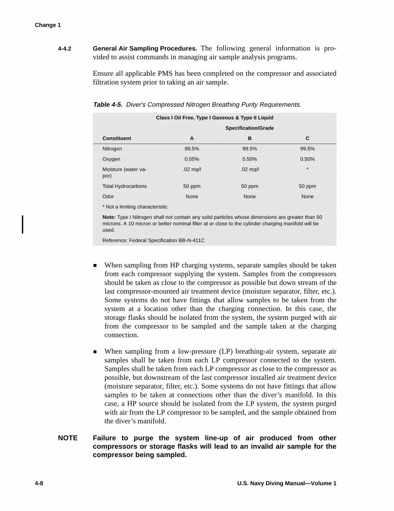
4-4.2 General Air Sampling Procedures. The following general information is pro-vided to assist commands in managing air sample analysis programs.
Ensure all applicable PMS has been completed on the compressor and associatedfiltration system prior to taking an air sample.
� When sampling from HP charging systems, separate samples should be takenfrom each compressor supplying the system. Samples from the compressorsshould be taken as close to the compressor as possible but down stream of thelast compressor-mounted air treatment device (moisture separator, filter, etc.).Some systems do not have fittings that allow samples to be taken from thesystem at a location other than the charging connection. In this case, thestorage flasks should be isolated from the system, the system purged with airfrom the compressor to be sampled and the sample taken at the chargingconnection.
� When sampling from a low-pressure (LP) breathing-air system, separate airsamples shall be taken from each LP compressor connected to the system.Samples shall be taken from each LP compressor as close to the compressor aspossible, but downstream of the last compressor installed air treatment device(moisture separator, filter, etc.). Some systems do not have fittings that allowsamples to be taken at connections other than the diver’s manifold. In thiscase, a HP source should be isolated from the LP system, the system purgedwith air from the LP compressor to be sampled, and the sample obtained fromthe diver’s manifold.
NOTE Failure to pur ge the system line-up of air produced from othercompressors or stora ge flasks will lead to an invalid air sample for thecompressor bein g sampled.
Table 4-5. Diver's Compressed Nitrogen Breathing Purity Requirements.
Class I Oil Free, Type I Gaseous & Type II Liquid
Specification/Grade
Constituent A B C
Nitrogen 99.5% 99.5% 99.5%
Oxygen 0.05% 0.50% 0.50%
Moisture (water va-por)
.02 mg/l .02 mg/l *
Total Hydrocarbons 50 ppm 50 ppm 50 ppm
Odor None None None
* Not a limiting characteristic
Note: Type I Nitrogen shall not contain any solid particles whose dimensions are greater than 50 microns. A 10 micron or better nominal filter at or close to the cylinder charging manifold will be used.
Reference: Federal Specification BB-N-411C
Change 1

CHAPTER 4 — Dive Systems 4-9
� Ensure that the compressor being sampled has reached full operating status(proper operating temperature, oil pressure, and air pressure) and is properlylined up to deliver air to the sample kit.
� Ensure that the compressor’s intake is clear of any potential sources ofcontamination (including consideration of ambient smog levels in areas wheresmog is a problem).
� Follow the procedures on applicable air sample MRC card.
� Follow the instructions for operation of the air sampling kit.
4-4.3 CSS Air Sampling Services. The following applies to centrally funded airsampling services coordinated by CSS. Due to limited funding, commands arerequested to schedule all compressors and associated samples to be taken at thesame time. CSS coordinates air sampling services with a commercial contractor.Commands are not authorized to communicate directly with the commercialcontractor. Sampling services are provided at no cost to the command. To requestair sampling services, fill out and fax Air Sampling services request to COAST-SYSTA (Attn: Air Sampling). Telephone numbers are listed in Appendix 1C.
� The user must provide the sample expiration date, the number and type (HP orLP) of samples required, a complete mailing address, user point of contact andphone number. Air sample kits will not be shipped until the requiredinformation is received.
� Allow a minimum of 5 working days after submitting a properly filled outrequest form for delivery of a sampling kit in CONUS. Kits will be sent viacommercial air with a prepaid return mailer. Incomplete sample requestscannot be acted on and will result in delay of shipping of sample kit.
� Allow a minimum of 3 weeks after submitting a properly filled out requestform for delivery of a sampling kit if overseas. Kits will be sent via certifiedpriority mail for overseas/FPO-APO addressees with prepaid return mailing.Incomplete sample requests cannot be acted on and will result in delay ofshipping of sample kit.
� Detailed instructions are included with each sample kit. It is imperative tofollow those instructions and the instructions on the applicable compressor airsampling MRC card.
� Air samples shall be taken and returned to COASTSYSTA within 5 workingdays of receipt of the air sample kit to preclude incurring late fees.
� Air sample analysis reports for samples that meet air purity standards will bemailed to the command. Commands will be notified by quickest meanspossible of any samples that do not meet minimum purity requirements.
Change 1

4-10 U.S. Navy Diving Manual—Volume 1
� The user will be contacted immediately by phone and/or message byCOASTSYSTA if the sample fails to meet established purity standards. Theuser will discontinue use of the air source until cause of contamination iscorrected. Corrective action must be taken prior to laboratory retest.
4-4.4 Local Air Sampling Services. Commands may use local government (e.g., ship-yards, ship repair facilities, government research laboratories) or commerciallaboratories to analyze diver’s air samples. Commands are required to bear thecost of locally procured air sample services. Local sampling facilities must be ableto analyze to U.S. Navy air purity standards.
4-5 DIVING COMPRESSORS
4-5.1 Equipment Requirements. Compressors used to supply diving air or transferoxygen or mixed gases shall be listed in the NAVSEA/00C Authorized for Navyuse (ANU) list or be an element of a certified diving system.
4-5.2 Air Filtration System. Military diving compressors shall be equipped with an airfiltration system that is listed in the NAVSEA/00C Authorized for Navy use(ANU) list or be an element of a certified diving system. The term air filtrationsystem as used here is inclusive, referring collectively to compressed gas systemfilters, moisture separators, air purification, air cooling, and dehydrationequipment.
4-5.3 Lubrication. Compressors used to produce military diver’s breathing air arenormally of oil-lubricated, two-to-five-stage reciprocating type. Oil lubrication:
� Prevents wear between friction surfaces
� Seals close clearances
� Protects against corrosion
� Transfers heat away from heat-producing surfaces
� Transfers minute particles generated from normal system wear to the oil sumpor oil filter if so equipped
A malfunctioning oil-lubricated compressor poses a contamination risk to thediver’s air supply. Contamination may occur due to excess oil mist being passedout of the compressor due to excess clearances, broken parts, or overfilling the oilsump.
Gaseous hydrocarbons and carbon monoxide may also be produced should acompressor overheat to the point of causing combustion of the lubricating oil and/or gaskets and other soft goods found in the compressor. Compressor overheatingmay be caused by a number of events including, but not limited to: loss of coolingwater or air flow, low lube oil level, malfunction of stage unloader or relief valves,

CHAPTER 5 — Dive Program Administration 5-1
C H A P T E R 5
'LYH�3URJUDP�$GPLQLVWUDWLRQ
5-1 INTRODUCTION
5-1.1 Purpose. The purpose of this chapter is to promulgate general policy for main-taining and retaining command smooth diving logs, personal diving logs, personaldiving records, diving mishap reports, and failure analysis reports.
5-1.2 Scope. The record keeping and reporting instructions outlined in this chapterpertain to command smooth diving logs, individual diving logs, personal divingrecords, diving mishap reports, and failure analysis reports.
5-2 OBJECTIVES OF THE RECORD KEEPING AND REPORTING SYSTEM
There are five objectives in the diving record keeping and reporting system.
1. Establish a comprehensive operational record for each diving command. TheCommand Smooth Diving Log is a standardized operational record preparedin accordance with established military practice. This record establishes thediving history for each diving command and constitutes the basic operationalrecord requirement under normal, uneventful circumstances.
2. Gather data for safety and trend analysis. Information about current divingoperations conducted in the Navy, the incidence of Hyperbaric Treatments,and diving mishaps is provided to the Naval Safety Center through the DivingReporting System and by message as required in OPNAVINST 5100.19CSection A-6. This information enables the Safety Center to identify safety-related problems associated with operating procedures and training.
3. Provide data for a personal record. OPNAVINST 3150.27 (series) requireseach diver to maintain a personal diving log/history.
4. Report information about diving mishaps and casualties in accordance withthe requirements of OPNAVINST 5100.19C Section A-6. Complete andaccurate information enables the command to take appropriate action andprevent reoccurrence.
5. Report information about equipment deficiencies to the responsible technicalagencies through the Failure Analysis Report (FAR) system.
5-3 RECORD KEEPING AND REPORTING DOCUMENTS
The documents established to meet the objectives of the record keeping andreporting system are:

5-2 U.S. Navy Diving Manual—Volume 1
� Command Smooth Diving Log (Figure 5-1a and Figure 5-1b)
� Dive Reporting System (DRS)
� Diver’s Personal Dive Record (diskette or hard copy)
� Diving Mishap/Hyperbaric Treatment/Death Report, Symbol OPNAV 5102/5
� Diving Mishaps reported in accordance with OPNAVINST 5100.19 SeriesAppendix A-6
� Equipment Accident/Incident Information Sheet (Figure 5-2a and Figure 5-2b)
� Diving Life Support Equipment Failure Analysis Report (FAR) for MK 20AGA, MK 21 surface-supplied diving system, and open-circuit scuba(NAVSEA Form 10560/4) (Figure 5-3)
� Failure Analysis Report for MK 16 UBA (NAVSEA Form 10560/1) (Figure5-4) or Failure Analysis or Inadequacy Report for MK 25 (LAR V).
5-4 COMMAND SMOOTH DIVING LOG
The Command Smooth Diving Log is a chronological record of all divesconducted at that facility or command. It contains information on dives bypersonnel attached to the reporting command and dives by personnel temporarilyattached to the command, such as personnel on TAD/TDY.
Dives conducted while temporarily assigned to another diving command shall berecorded in the host command’s Smooth Diving Log. Additionally, record the divein the Dive Reporting System (DRS) of the host command.
The OPNAVINST 3150.27 (series) requires commands to retain the official divinglog for 3 years. The minimum data items in the Command Smooth Diving Loginclude:
� Date of dive� Purpose of the dive� Identification of divers and standby divers� Times left and reached surface, bottom time� Depth� Decompression time� Air and water temperature� Signatures of Diving Supervisor or Diving Officer
5-5 RECOMPRESSION CHAMBER LOG
The Recompression Chamber Log is the official chronological record of proceduresand events for an entire dive. It is mandatory that all U.S. Navy diving activities main-tain a Recompression Chamber Log. The Diving Officer, Master Diver, and DivingSupervisor shall review and sign the log daily or at the end of their watches. The
Change 1
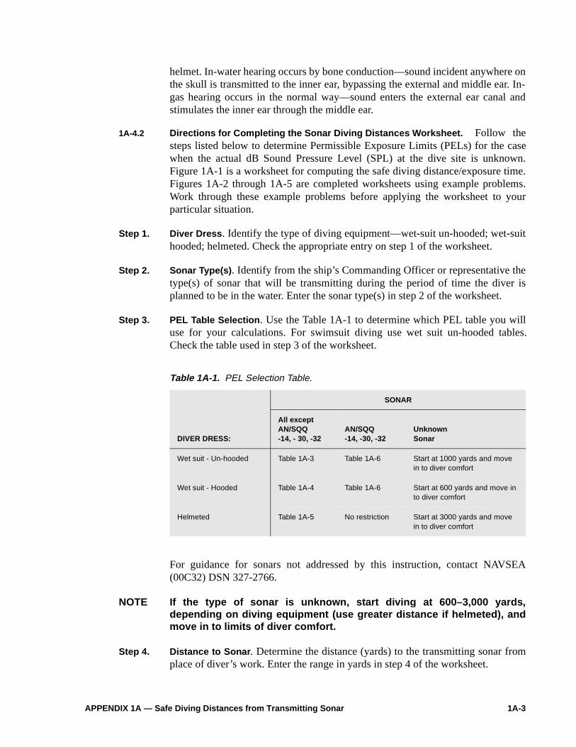
APPENDIX 1A — Safe Diving Distances from Transmitting Sonar 1A-3
helmet. In-water hearing occurs by bone conduction—sound incident anywhere onthe skull is transmitted to the inner ear, bypassing the external and middle ear. In-gas hearing occurs in the normal way—sound enters the external ear canal andstimulates the inner ear through the middle ear.
1A-4.2 Directions for Completing the Sonar Diving Distances Worksheet. Follow thesteps listed below to determine Permissible Exposure Limits (PELs) for the casewhen the actual dB Sound Pressure Level (SPL) at the dive site is unknown.Figure 1A-1 is a worksheet for computing the safe diving distance/exposure time.Figures 1A-2 through 1A-5 are completed worksheets using example problems.Work through these example problems before applying the worksheet to yourparticular situation.
Step 1. Diver Dress . Identify the type of diving equipment—wet-suit un-hooded; wet-suithooded; helmeted. Check the appropriate entry on step 1 of the worksheet.
Step 2. Sonar Type(s) . Identify from the ship’s Commanding Officer or representative thetype(s) of sonar that will be transmitting during the period of time the diver isplanned to be in the water. Enter the sonar type(s) in step 2 of the worksheet.
Step 3. PEL Table Selection . Use the Table 1A-1 to determine which PEL table you willuse for your calculations. For swimsuit diving use wet suit un-hooded tables.Check the table used in step 3 of the worksheet.
For guidance for sonars not addressed by this instruction, contact NAVSEA(00C32) DSN 327-2766.
NOTE If the type of sonar is unknown, start divin g at 600–3,000 yards,dependin g on divin g equipment (use greater distance if helmeted), andmove in to limits of diver comfort.
Step 4. Distance to Sonar . Determine the distance (yards) to the transmitting sonar fromplace of diver’s work. Enter the range in yards in step 4 of the worksheet.
Table 1A-1. PEL Selection Table.
SONAR
DIVER DRESS:
All except AN/SQQ-14, - 30, -32
AN/SQQ-14, -30, -32
UnknownSonar
Wet suit - Un-hooded Table 1A-3 Table 1A-6 Start at 1000 yards and move in to diver comfort
Wet suit - Hooded Table 1A-4 Table 1A-6 Start at 600 yards and move in to diver comfort
Helmeted Table 1A-5 No restriction Start at 3000 yards and move in to diver comfort

1A-4 U.S. Navy Diving Manual—Volume 1
SONAR SAFE DIVING DISTANCE/EXPOSURE TIME WORKSHEET
1. Diver dress: Wet Suit - Un-hooded Wet Suit - Hooded Helmeted
2. Type(s) of sonar:
3. PEL Table 1A-3 ; 1A-4 ; 1A-5 ; 1A-6
4. Range(s) to sonar (yards):
5. Estimated SPL at range(s) in step 3 (from table/column in step 3):
Reminder: If range is between two values in the table, use the shorter range . If the SPL is measured at the dive site, use the measured value.
6. Depth Reduction dB
Reminder : 0 if not helmeted, see table in instructions if helmeted .
7. Corrected SPL (Step 5 minus Step 6)
8. Estimated PEL at SPL (from table/column in step 3 of the appendix):
9. Duty Cycle Known: Yes (do step 9); No (stop)
Adjusted PEL for actual duty cycle
Actual DC % = 100 × sec. (pulse length / sec. (pulse repetition period)Actual DC % = Adjusted PEL = PEL (from step 8) min. × 20 / actual duty cycle (%) = min.
PEL1 = minutes; PEL2 = minutes
Reminder: Do not adjust the PEL if duty cycle is unknown.
10. Multiple Sonars: Yes (do step 10); No (stop)
Sonar 1: DT1 = (Desired dive duration)
PEL1 = (from Step 8 or 9, as applicable)
DT1/PEL1 = .
Sonar 2: DT1 = (Desired dive duration)
PEL1 = (from Step 8 or 9, as applicable)
DT1/PEL1 = .
ND = + = (This is less than 1.0, so dive is acceptable and may proceed.)
Reminder: The Noise Dose must not exceed a value of 1.0.
Figure 1A-1. Sonar Safe Diving Distance/Exposure Time Worksheet.
Change 1

APPENDIX 1A — Safe Diving Distances from Transmitting Sonar 1A-7
PEL1 (for SQS-53A) = 50 minutes DT1/PEL1 = 15/50 = .3
DT2 = 15 minutes PEL2 (for SQS-23) = 285 minutes DT2/PEL2 = 15/285 = .05
ND = .3 + .05 = .35This is less than 1.0 and therefore is acceptable.

1A-8 U.S. Navy Diving Manual—Volume 1
Example 1: You are planning a routine dive for 160 minutes using wet-suited divers without hoods at a divesite 17 yards from an AN/SQQ-14 sonar. The duty cycle for the AN/SQQ-14 sonar is unknown. Is this divepermitted? Provide justification for your decision.
SONAR SAFE DIVING DISTANCE/EXPOSURE TIME WORKSHEET
1. Diver dress: Wet Suit - Un-hooded X Wet Suit - Hooded Helmeted ______
2. Type(s) of sonar: AN/SQQ-14
3. PEL Table 1A-3 __; 1A-4 ; 1A-5 __; 1A-6 X
4. Range(s) to sonar (yards): 17
5. Estimated SPL at range(s) in step 3 (from table/column in step 3): SPL = 198 dB
Reminder: If range is between two values in the table, use the shorter range . If the SPL is measured at the dive site, use the measured value.
6. Depth Reduction 0 dB
Reminder : 0 if not helmeted, see table in instructions if helmeted .
7. Corrected SPL (Step 5 minus Step 6) SPL1 198 – 0 = 198 dB
8. Estimated PEL at SPL (from table/column in step 3 of the appendix): PEL1 = 170 minutes
9. Duty Cycle Known: Yes ______ (do step 9); No X (stop)Adjusted PEL for actual duty cycle
Actual DC % = 100 × _____ sec. (pulse length / _____ sec. (pulse repetition period)Actual DC % = ______Adjusted PEL = PEL (from step 8) ___ min. × 20 / actual duty cycle (%) ___ = ___ min.
Reminder: Do not adjust the PEL if duty cycle is unknown.
10. Multiple Sonars: Yes _____ (do step 10); No X (stop)
Sonar 1: DT1 = (Desired dive duration) PEL1 = (from Step 8 or 9, as applicable) DT1/PEL1 = .
Sonar 2: DT1 = (Desired dive duration) PEL1 = (from Step 8 or 9, as applicable) DT1/PEL1 = .
ND = ____ + _____ = ____ (This is less than 1.0, so dive is acceptable and may proceed.)
Reminder: The Noise Dose must not exceed a value of 1.0.
The dive time of 160 minutes is permitted because the PEL is 171 minutes.
Figure 1A-2. Sonar Safe Diving Distance/Exposure Time Worksheet (Completed Example).
Change 1

APPENDIX 1A — Safe Diving Distances from Transmitting Sonar 1A-9
Example 2: You are planning a routine dive for 75 minutes using wet-suited divers without hoods at a divesite which is 1000 yards from an AN/SQS-23 sonar. The SPL was measured at 185 dB. The duty cycle forthe AN/SQS-23 sonar is unknown. Is this dive permitted? Provide justification for your decision.
SONAR SAFE DIVING DISTANCE/EXPOSURE TIME WORKSHEET
1. Diver dress: Wet Suit - Un-hooded X Wet Suit - Hooded Helmeted ______
2. Type(s) of sonar: AN/SQS-23
3. PEL Table 1A-3 X ; 1A-4 ; 1A-5 __; 1A-6
4. Range(s) to sonar (yards): 1000
5. Estimated SPL at range(s) in step 3 (from table/column in step 3): SPL = 185 dB
Reminder: If range is between two values in the table, use the shorter range . If the SPL is measured at the dive site, use the measured value.
6. Depth Reduction 0 dB
Reminder : 0 if not helmeted, see table in instructions if helmeted .
7. Corrected SPL (Step 5 minus Step 6) SPL1 185 – 0 = 185 dB
8. Estimated PEL at SPL (from table/column in step 3 of the appendix): PEL1 = 170 minutes
9. Duty Cycle Known: Yes ______ (do step 9); No X (stop)Adjusted PEL for actual duty cycle
Actual DC % = 100 × _____ sec. (pulse length / _____ sec. (pulse repetition period)Actual DC % = ______Adjusted PEL = PEL (from step 8) ___ min. × 20 / actual duty cycle (%) ___ = ___ min.
Reminder: Do not adjust the PEL if duty cycle is unknown.
10. Multiple Sonars: Yes _____ (do step 10); No X (stop)
Sonar 1: DT1 = (Desired dive duration) PEL1 = (from Step 8 or 9, as applicable) DT1/PEL1 = .
Sonar 2: DT1 = (Desired dive duration) PEL1 = (from Step 8 or 9, as applicable) DT1/PEL1 = .
ND = ____ + _____ = ____ (This is less than 1.0, so dive is acceptable and may proceed.)Reminder: The Noise Dose must not exceed a value of 1.0.
The dive time of 75 minutes is permitted because the PEL is 170 minutes.
Figure 1A-3. Sonar Safe Diving Distance/Exposure Time Worksheet (Completed Example).
Change 1

1A-10 U.S. Navy Diving Manual—Volume 1
Example 3: You are planning a 98 fsw dive for 35 minutes using the MK 21 at a dive site which is 3000yards from an AN/SQS-53C sonar. The duty cycle for the AN/SQS-53C sonar is unknown. Is this divepermitted? Provide justification for your decision.
SONAR SAFE DIVING DISTANCE/EXPOSURE TIME WORKSHEET
1. Diver dress: Wet Suit - Un-hooded Wet Suit - Hooded Helmeted X
2. Type(s) of sonar: AN/SQS-53C
3. PEL Table 1A-3 ; 1A-4 ; 1A-5 X ; 1A-6
4. Range(s) to sonar (yards): 3000
5. Estimated SPL at range(s) in step 3 (from table/column in step 3): SPL1 = 181 dB
Reminder: If range is between two values in the table, use the shorter range . If the SPL is measured at the dive site, use the measured value.
6. Depth Reduction 6 dB
Reminder : 0 if not helmeted, see table in instructions if helmeted .
7. Corrected SPL (Step 5 minus Step 6) SPL1 181 – 6 = 175 dB
8. Estimated PEL at SPL (from table/column in step 3 of the appendix): PEL1 = 50 minutes
9. Duty Cycle Known: Yes ______ (do step 9); No X (stop)Adjusted PEL for actual duty cycle
Actual DC % = 100 × _____ sec. (pulse length / _____ sec. (pulse repetition period)Actual DC % = ______Adjusted PEL = PEL (from step 8) ___ min. × 20 / actual duty cycle (%) ___ = ___ min.
Reminder: Do not adjust the PEL if duty cycle is unknown.
10. Multiple Sonars: Yes _____ (do step 10); No X (stop)
Sonar 1: DT1 = (Desired dive duration) PEL1 = (from Step 8 or 9, as applicable) DT1/PEL1 = .
Sonar 2: DT1 = (Desired dive duration) PEL1 = (from Step 8 or 9, as applicable) DT1/PEL1 = .
ND = ____ + _____ = ____ (This is less than 1.0, so dive is acceptable and may proceed.)Reminder: The Noise Dose must not exceed a value of 1.0.
The dive time of 35 minutes is permitted because the PEL is 50 minutes.
Figure 1A-4. Sonar Safe Diving Distance/Exposure Time Worksheet (Completed Example).
Change 1

APPENDIX 1A — Safe Diving Distances from Transmitting Sonar 1A-11
Example 4: You are planning a routine dive for 120 minutes using wet-suited divers with hoods at a dive sitewhich is 200 yards from an AN/SQS-53A sonar and 120 yards from an AN/SQS-23 sonar. The AN/SQS-53Asonar is transmitting an 800 msec pulse (0.8 sec) every 20 seconds. The duty cycle for the AN/SQS-23sonar is unknown. Is this dive permitted? Provide justification for your decision.
SONAR SAFE DIVING DISTANCE/EXPOSURE TIME WORKSHEET
1. Diver dress: Wet Suit - Un-hooded Wet Suit - Hooded X Helmeted
2. Type(s) of sonar: AN/SQS-53A and AN/SQS-23
3. PEL Table 1A-3 ; 1A-4 X ; 1A-5 ; 1A-6
4. Range(s) to sonar (yards): 200 (from SQS-53A); 120 (from SQS-23)
5. Estimated SPL at range(s) in step 3 (from table/column in step 3): SPL1 = 201; SPL2 = 196(per reminder, use SPL for 112 yard range)Reminder: If range is between two values in the table, use the shorter range . If the SPL is measured at the dive site, use the measured value.
6. Depth Reduction 0 dB
Reminder : 0 if not helmeted, see table in instructions if helmeted .
7. Corrected SPL (Step 5 minus Step 6) SPL1 201 – 0 = 201 dB; SPL2 196 – 0 = 196 dB;
8. Estimated PEL at SPL (from table/column in step 3 of the appendix): PEL1 = 143 min; PEL 2 = 339 min
9. Duty Cycle Known: Yes X (do step 9); No (stop)Adjusted PEL for actual duty cycle
Actual DC % = 100 × 0.8 sec. (pulse length / 20 sec. (pulse repetition period)Actual DC % = 4 Adjusted PEL = PEL (from step 8) 143 min. × 20 / actual duty cycle (%) 4 = 715 min.PEL1 = 715 minutes; PEL2 = 339 minutes
Reminder: Do not adjust the PEL if duty cycle is unknown.
10. Multiple Sonars: Yes X (do step 10); No (stop)
Sonar 1: DT1 = 120 (Desired dive duration) PEL1 = 715 (from Step 8 or 9, as applicable) DT1/PEL1 = 120/715 = 0.17 .
Sonar 2: DT1 = 120 (Desired dive duration) PEL1 = 339 (from Step 8 or 9, as applicable) DT1/PEL1 = 120/339 = .35 .
ND = 0.17 + 0.35 = 0.52 (This is less than 1.0, so dive is acceptable and may proceed.)Reminder: The Noise Dose must not exceed a value of 1.0.
The dive time of 120 minutes is permitted because the ND is less than 1.0.
Figure 1A-5. Sonar Safe Diving Distance/Exposure Time Worksheet (Completed Example).
Change 1

1A-12 U.S. Navy Diving Manual—Volume 1
Table 1A-3. Wet Suit Un-Hooded.
Permissible Exposure Limit (PEL) within a 24-hour period for exposure to AN/SQS-23, -26, -53, -56,AN/BSY-1, -2 and AN/BQQ-5 sonars, including versions and upgrades. Exposure conditions shownabove the double line should be avoided except in cases of compelling operational necessity.
Estimated Ranges in yards for given SPL and PEL for sonar.
All ranges and SPLs are nominal.
*SPL is measured in dB/1 µPA at the dive site. To convert SPL for sound levels referenced to mbar,subtract 100 dB from tabled levels.
(U) = upgrade
SPL
(dB)
PEL
(MIN)BSY-1
SQS-53C
BQQ-5BSY-2
SQS-26CX(U)SQS-53A, SQS-53B
SQS-56(U)
SQS-23SQS-26AX
SQS-26BX, SQS-26CX SQS-56
200199198197196195194193192191
13151821253036425060
316355398447501562631708794891
224251282316355398447501562631
717989100112126141158178200
AV EO XI PD O
ST UH RI ES
190189188187186185184183182181180179178177176175
7185101120143170202240285339404480571679807960
1,0001,1221,2591,4131,5851,7781,9952,2392,5122,8183,1623,5483,9814,4675,0125,623
708794891
1,0001,1221,2591,4131,5851,7781,9952,2392,5122,8183,1623,5483,981
224251282316355398447501562631708794891
1,0001,1221,259

APPENDIX 1C — Telephone Numbers 1C-1
A P P E N D I X 1 C
7HOHSKRQH�1XPEHUV
Command Department Telephone Fax
Coastal Systems Station (CSS) Air Sampling DSN 436-4482 (850) 234-4482
COMNAVSEASYSCOM (Code 00C3) (703) 607-2766DSN 327-2766
(703) 607-2757
MED-21 (202) 762-3444
National Oceanic and Atmospheric Administration (NOAA)
HAZMAT (206) 526-6317 (206) 526-6329
Naval Facilities Engineering Command Code 00CE
(202) 433-8770
Naval Sea Systems Command Code
00C00C100C200C300C400C5
DirectorFinanceSalvageDivingCertificationHusbandry
DSN 327-XXXX
(703) 607-2753(703) 607-2762(703) 607-2758(703) 607-2766(703) 607-1570(703) 607-2761
(703) 607-2757DSN 327-2757
Naval Sea Systems Command Code 92Q
(703) 602-0141
NAVFAC 00CE Comm: (202) 433-8599 DSN: 288-8599
NAVFAC Code 00CE CertificationAcquisitions
(202) 433-8766(202) 433-5280
NAVFAC Ocean Facilities Program (703) 325-0505DSN 325-0505.
Navy Diving Salvage and Training Center (NDSTC)
Comm.:: (850) 234-4651 DSN: 436-4651
NCSC, Code 5110 DSN: 436-5414
Navy Experimental Diving Unit Comm: (850) 230-3100 or (850) 235-1668
DSN: 436-4351
Change 1

1C-2 U.S. Navy Diving Manual—Volume 1
PAGE LEFT BLANK INTENTIONALLY

Table of Contents–Volume 2 2-v
Chap/Para Page
7-4 AIR SUPPLY . . . . . . . . . . . . . . . . . . . . . . . . . . . . . . . . . . . . . . . . . . . . . . . . . . . . . . . . . . . . 7-13
7-4.1 Duration of Air Supply . . . . . . . . . . . . . . . . . . . . . . . . . . . . . . . . . . . . . . . . . . . . . 7-14
7-4.2 Compressed Air from Commercial Sources . . . . . . . . . . . . . . . . . . . . . . . . . . . . 7-16
7-4.3 Methods for Charging Scuba Cylinders . . . . . . . . . . . . . . . . . . . . . . . . . . . . . . . 7-17
7-4.4 Operating Procedures for Charging Scuba Tanks . . . . . . . . . . . . . . . . . . . . . . . 7-18
7-4.4.1 Topping off the Scuba Cylinder . . . . . . . . . . . . . . . . . . . . . . . . . . . .7-19
7-4.5 Safety Precautions for Charging and Handling Cylinders. . . . . . . . . . . . . . . . . . 7-20
7-5 PREDIVE PROCEDURES . . . . . . . . . . . . . . . . . . . . . . . . . . . . . . . . . . . . . . . . . . . . . . . . . . 7-21
7-5.1 Equipment Preparation . . . . . . . . . . . . . . . . . . . . . . . . . . . . . . . . . . . . . . . . . . . . 7-21
7-5.1.1 Air Cylinders . . . . . . . . . . . . . . . . . . . . . . . . . . . . . . . . . . . . . . . . . . .7-217-5.1.2 Harness Straps and Backpack . . . . . . . . . . . . . . . . . . . . . . . . . . . . .7-227-5.1.3 Breathing Hoses . . . . . . . . . . . . . . . . . . . . . . . . . . . . . . . . . . . . . . . .7-227-5.1.4 Regulator . . . . . . . . . . . . . . . . . . . . . . . . . . . . . . . . . . . . . . . . . . . ..7-227-5.1.5 Life Preserver/Buoyancy Compensator (BC) . . . . . . . . . . . . . . . . . .7-227-5.1.6 Face Mask . . . . . . . . . . . . . . . . . . . . . . . . . . . . . . . . . . . . . . . . . . ..7-237-5.1.7 Swim Fins . . . . . . . . . . . . . . . . . . . . . . . . . . . . . . . . . . . . . . . . . . . ..7-237-5.1.8 Dive Knife . . . . . . . . . . . . . . . . . . . . . . . . . . . . . . . . . . . . . . . . . . . ..7-237-5.1.9 Snorkel . . . . . . . . . . . . . . . . . . . . . . . . . . . . . . . . . . . . . . . . . . . . . ..7-237-5.1.10 Weight Belt . . . . . . . . . . . . . . . . . . . . . . . . . . . . . . . . . . . . . . . . . . ..7-237-5.1.11 Submersible Wrist Watch . . . . . . . . . . . . . . . . . . . . . . . . . . . . . . . . .7-237-5.1.12 Depth Gauge and Compass . . . . . . . . . . . . . . . . . . . . . . . . . . . . . . .7-237-5.1.13 Miscellaneous Equipment. . . . . . . . . . . . . . . . . . . . . . . . . . . . . . . . .7-24
7-5.2 Diver Preparation and Brief. . . . . . . . . . . . . . . . . . . . . . . . . . . . . . . . . . . . . . . . . 7-24
7-5.3 Donning Gear . . . . . . . . . . . . . . . . . . . . . . . . . . . . . . . . . . . . . . . . . . . . . . . . . . . 7-24
7-5.4 Predive Inspection . . . . . . . . . . . . . . . . . . . . . . . . . . . . . . . . . . . . . . . . . . . . . . . 7-25
7-6 WATER ENTRY AND DESCENT . . . . . . . . . . . . . . . . . . . . . . . . . . . . . . . . . . . . . . . . . . . . 7-26
7-6.1 Water Entry . . . . . . . . . . . . . . . . . . . . . . . . . . . . . . . . . . . . . . . . . . . . . . . . . . . . . 7-26
7-6.1.1 Step-In Method . . . . . . . . . . . . . . . . . . . . . . . . . . . . . . . . . . . . . . . . .7-287-6.1.2 Rear Roll Method . . . . . . . . . . . . . . . . . . . . . . . . . . . . . . . . . . . . . . .7-287-6.1.3 Entering the Water from the Beach . . . . . . . . . . . . . . . . . . . . . . . . .7-28
7-6.2 Predescent Surface Check . . . . . . . . . . . . . . . . . . . . . . . . . . . . . . . . . . . . . . . . . 7-28
7-6.3 Surface Swimming . . . . . . . . . . . . . . . . . . . . . . . . . . . . . . . . . . . . . . . . . . . . . . . 7-29
7-6.4 Descent. . . . . . . . . . . . . . . . . . . . . . . . . . . . . . . . . . . . . . . . . . . . . . . . . . . . . . . . 7-29
7-7 UNDERWATER PROCEDURES . . . . . . . . . . . . . . . . . . . . . . . . . . . . . . . . . . . . . . . . . . . . . 7-30
7-7.1 Breathing Technique. . . . . . . . . . . . . . . . . . . . . . . . . . . . . . . . . . . . . . . . . . . . . . 7-30
7-7.2 Mask Clearing . . . . . . . . . . . . . . . . . . . . . . . . . . . . . . . . . . . . . . . . . . . . . . . . . . . 7-30
7-7.3 Hose and Mouthpiece Clearing. . . . . . . . . . . . . . . . . . . . . . . . . . . . . . . . . . . . . . 7-30
7-7.4 Swimming Technique . . . . . . . . . . . . . . . . . . . . . . . . . . . . . . . . . . . . . . . . . . . . . 7-31
7-7.5 Diver Communications . . . . . . . . . . . . . . . . . . . . . . . . . . . . . . . . . . . . . . . . . . . . 7-31
7-7.5.1 Through-Water Communication Systems. . . . . . . . . . . . . . . . . . . . .7-327-7.5.2 Hand and Line-Pull Signals . . . . . . . . . . . . . . . . . . . . . . . . . . . . . . .7-32
2-vi U.S. Navy Diving Manual—Volume 2
Chap/Para Page
7-7.6 Buddy Diver Responsibilities . . . . . . . . . . . . . . . . . . . . . . . . . . . . . . . . . . . . . . . 7-32
7-7.7 Buddy Breathing Procedure . . . . . . . . . . . . . . . . . . . . . . . . . . . . . . . . . . . . . . . . 7-35
7-7.8 Tending. . . . . . . . . . . . . . . . . . . . . . . . . . . . . . . . . . . . . . . . . . . . . . . . . . . . . . . . 7-36
7-7.8.1 Tending with a Surface or Buddy Line . . . . . . . . . . . . . . . . . . . . . . .7-367-7.8.2 Tending with No Surface Line . . . . . . . . . . . . . . . . . . . . . . . . . . . . .7-37
7-7.9 Working with Tools . . . . . . . . . . . . . . . . . . . . . . . . . . . . . . . . . . . . . . . . . . . . . . . 7-37
7-7.10 Adapting to Underwater Conditions . . . . . . . . . . . . . . . . . . . . . . . . . . . . . . . . . . 7-37
7-8 ASCENT PROCEDURES . . . . . . . . . . . . . . . . . . . . . . . . . . . . . . . . . . . . . . . . . . . . . . . . . . 7-38
7-8.1 Emergency Free-Ascent Procedures . . . . . . . . . . . . . . . . . . . . . . . . . . . . . . . . . 7-38
7-8.2 Ascent From Under a Vessel . . . . . . . . . . . . . . . . . . . . . . . . . . . . . . . . . . . . . . . 7-39
7-8.3 Decompression. . . . . . . . . . . . . . . . . . . . . . . . . . . . . . . . . . . . . . . . . . . . . . . . . . 7-39
7-8.4 Surfacing and Leaving the Water . . . . . . . . . . . . . . . . . . . . . . . . . . . . . . . . . . . . 7-40
7-9 POSTDIVE PROCEDURES . . . . . . . . . . . . . . . . . . . . . . . . . . . . . . . . . . . . . . . . . . . . . . . . 7-40
8 SURFACE-SUPPLIED AIR DIVING OPERATIONS
8-1 INTRODUCTION . . . . . . . . . . . . . . . . . . . . . . . . . . . . . . . . . . . . . . . . . . . . . . . . . . . . . . . . . . 8-1
8-1.1 Purpose . . . . . . . . . . . . . . . . . . . . . . . . . . . . . . . . . . . . . . . . . . . . . . . . . . . . . . . . 8-1
8-1.2 Scope . . . . . . . . . . . . . . . . . . . . . . . . . . . . . . . . . . . . . . . . . . . . . . . . . . . . . . . . . . 8-1
8-2 MK 21 MOD 1 . . . . . . . . . . . . . . . . . . . . . . . . . . . . . . . . . . . . . . . . . . . . . . . . . . . . . . . . . . . . 8-1
8-2.1 Operation and Maintenance . . . . . . . . . . . . . . . . . . . . . . . . . . . . . . . . . . . . . . . . . 8-1
8-2.2 Air Supply . . . . . . . . . . . . . . . . . . . . . . . . . . . . . . . . . . . . . . . . . . . . . . . . . . . . . . . 8-1
8-2.2.1 Emergency Gas Supply Requirements . . . . . . . . . . . . . . . . . . . . . . .8-28-2.2.2 Flow Requirements . . . . . . . . . . . . . . . . . . . . . . . . . . . . . . . . . . . . . .8-28-2.2.3 Pressure Requirements . . . . . . . . . . . . . . . . . . . . . . . . . . . . . . . . . . .8-2
8-3 MK 20 MOD 0 . . . . . . . . . . . . . . . . . . . . . . . . . . . . . . . . . . . . . . . . . . . . . . . . . . . . . . . . . . . . 8-5
8-3.1 Operation and Maintenance . . . . . . . . . . . . . . . . . . . . . . . . . . . . . . . . . . . . . . . . . 8-5
8-3.2 Air Supply . . . . . . . . . . . . . . . . . . . . . . . . . . . . . . . . . . . . . . . . . . . . . . . . . . . . . . . 8-6
8-3.2.1 EGS Requirements for MK 20 MOD 0 Enclosed-Space Diving . . . . .8-68-3.2.2 EGS Requirements for MK 20 MOD 0 Open Water Diving . . . . . . . .8-68-3.2.3 Flow Requirements . . . . . . . . . . . . . . . . . . . . . . . . . . . . . . . . . . . . . .8-6
8-4 PORTABLE SURFACE-SUPPLIED DIVING SYSTEMS . . . . . . . . . . . . . . . . . . . . . . . . . . . 8-6
8-4.1 MK 3 MOD 0 Lightweight Dive System (LWDS). . . . . . . . . . . . . . . . . . . . . . . . . . 8-6
8-4.1.1 MK 3 MOD 0 Configuration 1. . . . . . . . . . . . . . . . . . . . . . . . . . . . . . .8-78-4.1.2 MK 3 MOD 0 Configuration 2. . . . . . . . . . . . . . . . . . . . . . . . . . . . . . .8-78-4.1.3 MK 3 MOD 0 Configuration 3. . . . . . . . . . . . . . . . . . . . . . . . . . . . . . .8-7
8-4.2 MK 3 MOD 1 Lightweight Dive System. . . . . . . . . . . . . . . . . . . . . . . . . . . . . . . . . 8-7
8-4.3 ROPER Diving Cart . . . . . . . . . . . . . . . . . . . . . . . . . . . . . . . . . . . . . . . . . . . . . . . 8-9
8-4.4 Flyaway Dive System (FADS) I . . . . . . . . . . . . . . . . . . . . . . . . . . . . . . . . . . . . . . 8-9
Change 1

List of Tables–Volume 2 2-xvii
9ROXPH�����/LVW�RI�7DEOHV
Table Page
7-1 Sample Scuba Cylinder Data. . . . . . . . . . . . . . . . . . . . . . . . . . . . . . . . . . . . . . . . . . . . . . . . . 7-5
8-0 MK 21 MOD 1 Overbottom Pressure Requirements . . . . . . . . . . . . . . . . . . . . . . . . . . . . . . . 8-2
8-1 Primary Air System Requirements. . . . . . . . . . . . . . . . . . . . . . . . . . . . . . . . . . . . . . . . . . . . 8-14
8-2 Line-Pull Signals. . . . . . . . . . . . . . . . . . . . . . . . . . . . . . . . . . . . . . . . . . . . . . . . . . . . . . . . . 8-23
9-1 Pneumofathometer Correction Factors. . . . . . . . . . . . . . . . . . . . . . . . . . . . . . . . . . . . . . . . . 9-2
9-2 Air Decompression Tables Selection Criteria. . . . . . . . . . . . . . . . . . . . . . . . . . . . . . . . . . . . . 9-7
9-3 Sea Level Equivalent Depth (fsw). . . . . . . . . . . . . . . . . . . . . . . . . . . . . . . . . . . . . . . . . . . . 9-41
9-4 Repetitive Groups Associated with Initial Ascent to Altitude. . . . . . . . . . . . . . . . . . . . . . . . 9-43
9-5 Required Surface Interval Before Ascent to Altitude After Diving. . . . . . . . . . . . . . . . . . . . 9-53
9-6 Unlimited/No-Decompression Limits and Repetitive Group Designation Table for Unlimited/No-Decompression Air Dives. . . . . . . . . . . . . . . . . . . . . . . . . . . . . . . . 9-54
9-7 Residual Nitrogen Timetable for Repetitive Air Dives. . . . . . . . . . . . . . . . . . . . . . . . . . . . . 9-55
9-8 U.S. Navy Standard Air Decompression Table. . . . . . . . . . . . . . . . . . . . . . . . . . . . . . . . . . 9-56
9-8 U.S. Navy Standard Air Decompression Table (Continued). . . . . . . . . . . . . . . . . . . . . . . . 9-62
9-9 Surface Decompression Table Using Oxygen. . . . . . . . . . . . . . . . . . . . . . . . . . . . . . . . . . . 9-64
9-10 Surface Decompression Table Using Air. . . . . . . . . . . . . . . . . . . . . . . . . . . . . . . . . . . . . . . 9-67
10-1 Equivalent Air Depth Table. . . . . . . . . . . . . . . . . . . . . . . . . . . . . . . . . . . . . . . . . . . . . . . . . 10-4
10-2 Oil-Free Air. . . . . . . . . . . . . . . . . . . . . . . . . . . . . . . . . . . . . . . . . . . . . . . . . . . . . . . . . . . . . 10-11
Change 1

2-xviii U.S. Navy Diving Manual—Volume 2
Table Page
Page Left Blank Intentionally
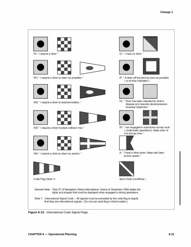
CHAPTER 6 — Operational Planning 6-21
Figure 6-12. International Code Signal Flags.
Change 1

6-22 U.S. Navy Diving Manual—Volume 2
1. Open-circuit scuba
2. MK 20 MOD 0 surface-supplied gear
3. MK 21 MOD 1 surface-supplied gear
6-7.1 Factors to Consider when Selecting the Diving Technique. When selecting thetechnique to be used for a dive, the following factors must be considered:
� Duration and depth of the dive� Type of work to be performed� Environmental conditions� Time constraints
A dive of extended length, even in shallow water, may require an air supplyexceeding that which could be provided by scuba. Specific depth limits have beenestablished for each type of diving gear and shall not be exceeded without specificapproval of the Chief of Naval Operations in accordance with the OPNAVINST3150.27 series (see Figure 6-14).
Figure 6-13. Air Diving Techniques. A choice of three air diving techniques are available: open circuit scuba,surface-supplied gear (MK 20 MOD 0), and surface-supplied deep-sea gear (MK 21 MOD 1).
OPEN-CIRCUIT SCUBANormal working limit: 130 fswOperational necessity: 190 fsw
SURFACE-SUPPLIED GEAR(MK 20 MOD 0)Normal working limit with EGS: 60 fsw
SURFACE-SUPPLIED DEEP-SEA GEAR(MK 21 MOD 1)Normal working limit with EGS: 190 fsw

CHAPTER 7 — Scuba Air Diving Operations 7-3
Figure 7-1. Schematic of Demand Regulator.
First Stage. High pressure air flows through the orifice of the first stage into the intermediate chamber. When the pressure in the intermediate chamber reaches ambient plus diaphragm balance spring set pressure, the first stage assembly closes.
Second Stage. Upon inhalation the second stage diaphragm moves inward and the horseshoe lever opens the second stage valve assembly. Intermediate pressure air from the hoses is throttled across the orifice and fills the low pressure chamber to ambient pressure and flow is provided to the diver. Upon exhalation the diaphragm is pushed outward and the second stage in closed. Expired air is dumped from the low pressure chamber to the surrounding water through the exhaust valve.

7-4 U.S. Navy Diving Manual—Volume 2
octopus hose is an alternative and preferred method to accomplish buddybreathing. An octupus is mandatory for standby diver and recommended for allSCUBA divers. The principal disadvantages of the single-hose unit are anincreased tendency to freeze up in very cold water and the exhaust of air in front ofthe diver’s mask. While the Navy PMS system provides guidance for repairingand maintaining scuba regulators, the manufacturer’s service manual should befollowed for specific procedures.
7-2.2.1.4 Full Face Mask. The AGA/Divator full face mask may be used with an approvedsingle-hose first-stage regulator with an octopus, to the maximum approved depthof the regulator, as indicated in the NAVSEA/00C ANU list (Figure 7-2).
7-2.2.1.5 Mouthpiece. The size and design of scuba mouthpieces differ between manufac-turers, but each mouthpiece provides relatively watertight passageways fordelivering breathing air into the diver’s mouth. The mouthpiece should fitcomfortably with slight pressure from the lips.
7-2.2.2 Cylinders. Scuba cylinders (tanks or bottles) are designed to hold high pressurecompressed air. Because of the extreme stresses imposed on a cylinder at thesepressures, all cylinders used in scuba diving must be inspected and tested periodi-cally. Seamless steel or aluminum cylinders which meet Department ofTransportation (DOT) specifications (DOT 3AA, DOT 3AL, DOT SP6498, andDOT E6498) are approved for Navy use. Each cylinder used in Navy operationsmust have identification symbols stamped into the shoulder (Figure 7-3).
7-2.2.2.1 Sizes of Approved Scuba Cylinders. Approved scuba cylinders are available inseveral sizes and one or two cylinders may be worn to provide the required quan-tity of air for the dive. The volume of a cylinder, expressed in actual cubic feet or
Figure 7-2. Full Face Mask.
Change 1
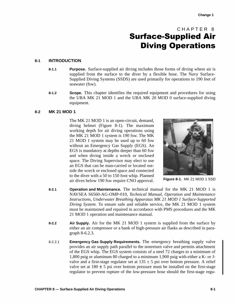
CHAPTER 8 — Surface-Supplied Air Diving Operations 8-1
C H A P T E R 8
6XUIDFH�6XSSOLHG�$LU
'LYLQJ�2SHUDWLRQV
8-1 INTRODUCTION
8-1.1 Purpose. Surface-supplied air diving includes those forms of diving where air issupplied from the surface to the diver by a flexible hose. The Navy Surface-Supplied Diving Systems (SSDS) are used primarily for operations to 190 feet ofseawater (fsw).
8-1.2 Scope. This chapter identifies the required equipment and procedures for usingthe UBA MK 21 MOD 1 and the UBA MK 20 MOD 0 surface-supplied divingequipment.
8-2 MK 21 MOD 1
The MK 21 MOD 1 is an open-circuit, demand,diving helmet (Figure 8-1). The maximumworking depth for air diving operations usingthe MK 21 MOD 1 system is 190 fsw. The MK21 MOD 1 system may be used up to 60 fswwithout an Emergency Gas Supply (EGS). AnEGS is mandatory at depths deeper than 60 fswand when diving inside a wreck or enclosedspace. The Diving Supervisor may elect to usean EGS that can be man-carried or located out-side the wreck or enclosed space and connectedto the diver with a 50 to 150 foot whip. Plannedair dives below 190 fsw require CNO approval.
8-2.1 Operation and Maintenance. The technical manual for the MK 21 MOD 1 isNAVSEA S6560-AG-OMP-010, Technical Manual, Operation and MaintenanceInstructions, Underwater Breathing Apparatus MK 21 MOD 1 Surface-SupportedDiving System. To ensure safe and reliable service, the MK 21 MOD 1 systemmust be maintained and repaired in accordance with PMS procedures and the MK21 MOD 1 operation and maintenance manual.
8-2.2 Air Supply. Air for the MK 21 MOD 1 system is supplied from the surface byeither an air compressor or a bank of high-pressure air flasks as described in para-graph 8-6.2.3.
8-2.2.1 Emergency Gas Supply Requirements. The emergency breathing supply valveprovides an air supply path parallel to the nonreturn valve and permits attachmentof the EGS whip. The EGS system consists of a steel 72 charges to a minimum of1,800 psig or aluminum 80 charged to a minimum 1,900 psig with either a K- or J-valve and a first-stage regulator set at 135 ± 5 psi over bottom pressure. A reliefvalve set at 180 ± 5 psi over bottom pressure must be installed on the first-stageregulator to prevent rupture of the low-pressure hose should the first-stage regu-
Figure 8-1. MK 21 MOD 1 SSD
Change 1

8-2 U.S. Navy Diving Manual—Volume 2
lator fail. The flexible low-pressure hose from the first-stage regulator attaches tothe emergency supply valve on the helmet sideblock. A submersible pressuregauge is also required on the first-stage regulator.
When using an EGS whip 50 to 100 feet in length, set at manufacturer’s recom-mended pressure, but not lower than 135 psi. If the diving scenario dictatesleaving the EGS topside, adjust the first-stage regulator to 150 psig.
When conducting open water dives 60 fsw and shallower, the diving supervisormay use an ANU approved cylinder designated for MK 21 as an emergency airsource.
8-2.2.2 Flow Requirements. When the MK 21 MOD 1 system is used, the air supplysystem must be able to provide an average sustained flow of 1.4 acfm to the diver.The air consumption of divers using the MK 21 MOD 1 varies between 0.75 and1.5 acfm when used in a demand mode, with occasional faceplate and maskclearing. When used in a free-flow mode, greater than eight acfm is consumed.
NOTE When plannin g a dive, calculations are based on 1.4 acfm.
To satisfactorily support the MK 21 MOD 1 system, the air supply must:
� Replenish the air consumed from the system (average rate of flow)
� Replenish the air at a rate sufficient to maintain the required pressure
� Provide the maximum rate of flow required by the diver
8-2.2.3 Pressure Requirements. Because the MK 21 MOD 1 helmet is a demand-typesystem, the regulator has an optimum overbottom pressure that ensures the lowestpossible breathing resistance and reduces the possibility of overbreathing the regu-lator (demanding more air than is available). For those systems not capable ofsustaining 165 psi overbottom due to design limitations, 135 psi overbottom isacceptable. Table 8-0 shows the MK 21 MOD 1 overbottom pressurerequirements.
This ensures that the air supply will deliver air at a pressure sufficient to overcomebottom seawater pressure and the pressure drop that occurs as the air flowsthrough the hoses and valves of the mask.
Sample Problem 1. Determine the air supply manifold pressure required to divethe MK 21 MOD 1 system to 175 fsw.
Table 8-0. MK 21 MOD 1 Overbottom Pressure Requirements.
Pressure in psig
Dive Depth Minimum Desired Maximum
0-60 fsw 90* 135 165
61-130 fsw 135 135 165
131-190 FSW 165** 165 165
*Not approved for use with a double exhaust kit installed. Instead use a minimum of 135 psig.**For diver life support systems not capable of sustaining 165 psig overbottom due to system design lim-itations, 135 psig is authorized.
Change 1

CHAPTER 8 — Surface-Supplied Air Diving Operations 8-3
1. Determine the bottom pressure at 175 fsw:
Bottom pressure at 175 fsw = 175 × .445 psi
= 77.87 psig (round to 78)
2. Determine the overbottom pressure for the MK 21 MOD 1 system (seeparagraph 8-2.2.3). Because the operating depth is 175 fsw, the overbottompressure is 165 psig.
3. Calculate the minimum manifold pressure (MMP) by adding the bottompressure to the overbottom pressure:
The minimum manifold pressure for a 175-fsw dive must be 243 psig.
Sample Problem 2. Determine if air from a bank of high-pressure flasks iscapable of supporting two MK 21 MOD 1 divers and one standby diver at a depthof 130 fsw for 30 minutes. There are 5 flasks in the bank; only 4 are on line. Eachflask has a floodable volume of 8 cubic feet and is charged to 3,000 psig.
NOTE These calculations are based on an assumption of an avera ge of 1.4acfm diver air consumption over the total time of the dive. Hi gher con-sumption over short periods can be expected based on diver work rate.
1. Calculate minimum manifold pressure (MMP).
Round up to 223 psig
2. Calculate standard cubic feet (scf) of air available. The formula for calculatingthe scf of air available is:
Where:Pf = Flask pressure = 3,000 psigPmf = Minimum flask pressure = 200 psigMMP = 223 psig V = Capacity of flasks = 8 cffvN = Number of flasks = 4
MMP 78 psig 165 psig+=
243 psig=
MMP psig( ) 0.445D( ) 165 psig+=
0.455 130×( ) 165 psig+=
222.85 psig=
scf availablePf Pmf MMP+( )–
14.7---------------------------------------------- V× N×=
Change 1
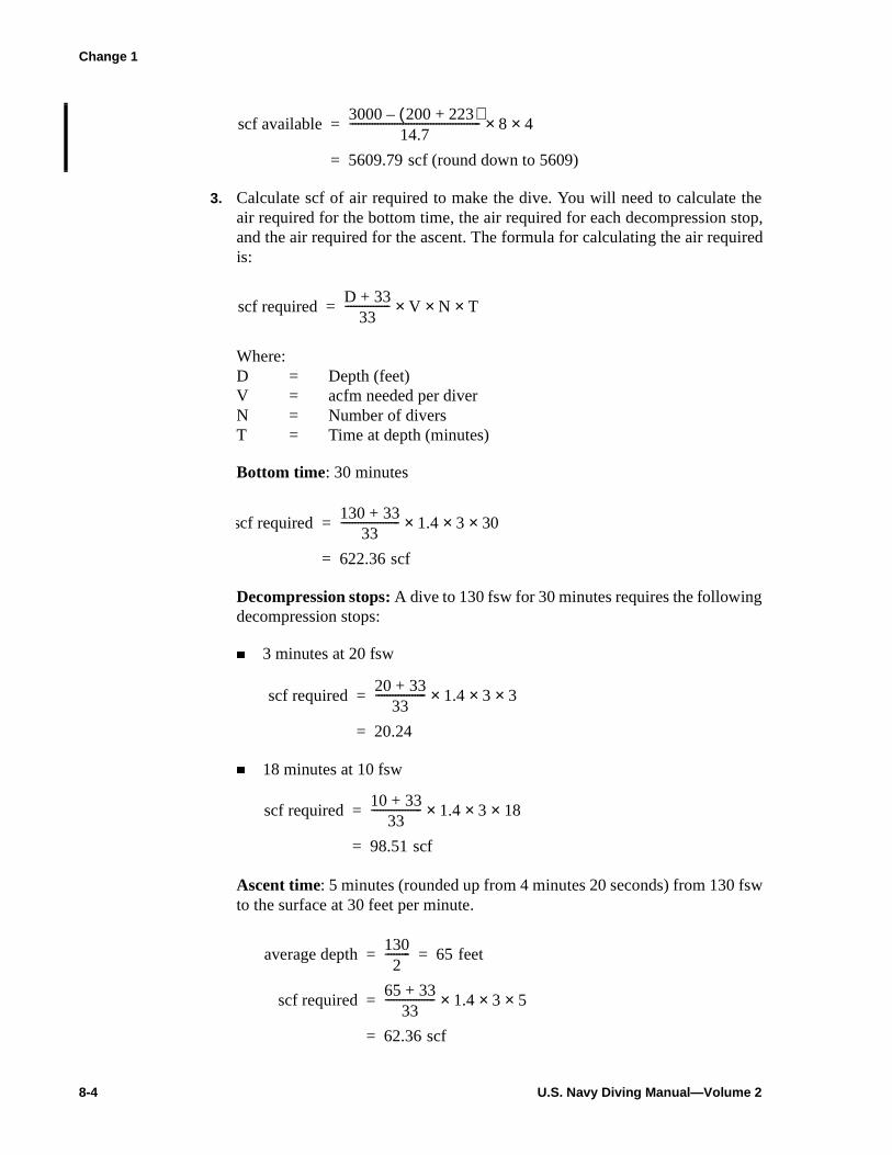
8-4 U.S. Navy Diving Manual—Volume 2
3. Calculate scf of air required to make the dive. You will need to calculate theair required for the bottom time, the air required for each decompression stop,and the air required for the ascent. The formula for calculating the air requiredis:
Where:D = Depth (feet)V = acfm needed per diverN = Number of diversT = Time at depth (minutes)
Bottom time: 30 minutes
Decompression stops: A dive to 130 fsw for 30 minutes requires the followingdecompression stops:
� 3 minutes at 20 fsw
� 18 minutes at 10 fsw
Ascent time: 5 minutes (rounded up from 4 minutes 20 seconds) from 130 fswto the surface at 30 feet per minute.
scf available3000 200 223+( )–
14.7----------------------------------------------- 8× 4×=
5609.79 scf (round down to 5609)=
scf requiredD 33+
33---------------- V N× T××=
scf required130 33+
33--------------------- 1.4 3× 30××=
622.36 scf=
scf required20 33+
33------------------ 1.4 3× 3××=
20.24=
scf required10 33+
33------------------ 1.4 3× 18××=
98.51 scf=
average depth1302
--------- 65 feet= =
scf required65 33+
33------------------ 1.4 3× 5××=
62.36 scf=
Change 1
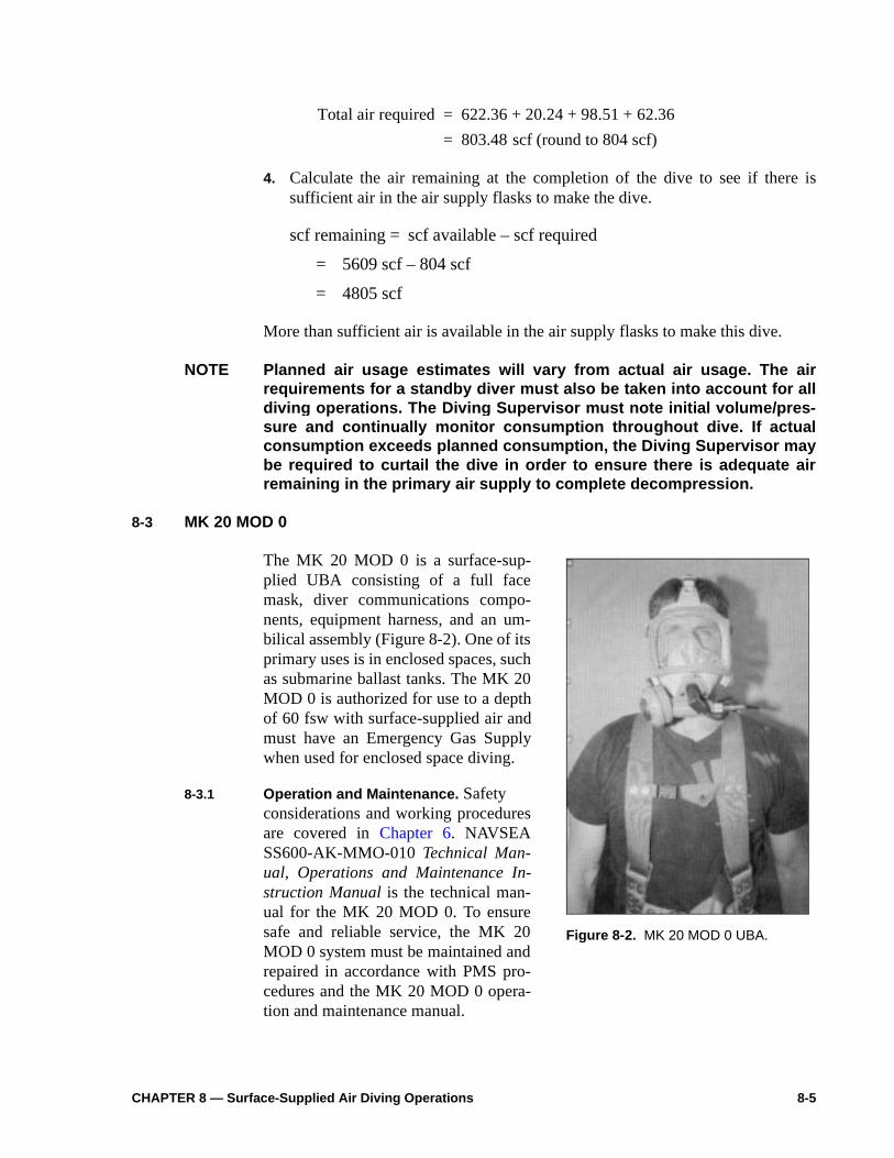
re is
4. Calculate the air remaining at the completion of the dive to see if thesufficient air in the air supply flasks to make the dive.scf remaining = scf available – scf required
= 5609 scf – 804 scf
= 4805 scf
More than sufficient air is available in the air supply flasks to make this dive.
NOTE Planned air usa ge estimates will vary from actual air usa ge. The airrequirements for a standby diver must also be taken into account for alldivin g operations. The Divin g Supervisor must note initial volume/pres-sure and continually monitor consumption throu ghout dive. If actualconsumption exceeds planned consumption, the Divin g Supervisor maybe required to curtail the dive in order to ensure there is adequate airremainin g in the primary air supply to complete decompression.
8-3 MK 20 MOD 0
The MK 20 MOD 0 is a surface-sup-plied UBA consisting of a full facemask, diver communications compo-nents, equipment harness, and an um-bilical assembly (Figure 8-2). One of itsprimary uses is in enclosed spaces, suchas submarine ballast tanks. The MK 20MOD 0 is authorized for use to a depthof 60 fsw with surface-supplied air andmust have an Emergency Gas Supplywhen used for enclosed space diving.
8-3.1 Operation and Maintenance. Safetyconsiderations and working proceduresare covered in Chapter 6. NAVSEASS600-AK-MMO-010 Technical Man-ual, Operations and Maintenance In-struction Manual is the technical man-ual for the MK 20 MOD 0. To ensuresafe and reliable service, the MK 20MOD 0 system must be maintained andrepaired in accordance with PMS pro-cedures and the MK 20 MOD 0 opera-tion and maintenance manual.
Total air required 622.36 20.24 98.51 62.36+ + +=
803.48 scf (round to 804 scf)=
Figure 8-2. MK 20 MOD 0 UBA.
CHAPTER 8 — Surface-Supplied Air Diving Operations 8-5

by para-
mud used.
ini-
re, butth. If reg-
arriedpace EGSo theediate
oved
.4 calcu-
They bees aressorf threeflaskidesder- fswortpinte-
Change 1
8-3.2 Air Supply. Air for the MK 20 MOD 0 system is supplied from the surface either an air compressor or a bank of high-pressure flasks as described ingraph 8-6.2.3.
8-3.2.1 EGS Requirements for MK 20 MOD 0 Enclosed-Space Diving. In order to ensurea positive emergency air supply to the diver when working in a ballast tank, tank, or confined space, an Emergency Gas Supply (EGS) assembly must beAs a minimum, the EGS assembly consists of:
� Single scuba cylinder steel 72 with either a K- or J-valve, charged to a mmum of 1,800 psi or aluminum 80 charged to 1,900 psi.
� An approved scuba regulator set at manufacturer’s recommended pressunot lower than 135 psi, with an extended EGS whip 50 to 150 feet in lengthe diving scenario dictates leaving the EGS topside, adjust the first-stageulator to 150 psig.
� An approved submersible pressure gauge.
The scuba cylinder may be left on the surface and the EGS whip may be mto the diver’s umbilical, or it may be secured at the opening of the enclosed sbeing entered. The diver may then enter the work space with the extendedwhip trailing. The second-stage regulator of the EGS is securely attached tdiver’s harness before entering the work space so that the diver has immaccess to the EGS regulator in an emergency.
8-3.2.2 EGS Requirements for MK 20 MOD 0 Open Water Diving. When conducting openwater dives, the diving supervisor may use a MK 20 designated ANU apprcylinder with the DSI sideback assembly as an emergency air source.
8-3.2.3 Flow Requirements. The MK 20 MOD 0 requires a breathing gas flow of 1acfm and an overbottom pressure of 90 psig. Flow and pressure requirementlations are identical to those for the MK 21 MOD 1 (see paragraph 8-2.2.3).
8-4 PORTABLE SURFACE-SUPPLIED DIVING SYSTEMS
8-4.1 MK 3 MOD 0 Lightweight Dive System (LWDS). The MK 3 MOD 0 LWDS is aportable, self-contained, surface-supplied diver life-support system (DLSS).MK 3 MOD 0 LWDS can be arranged in three different configurations and madeployed pierside or from a variety of support platforms. Each LWDS includcontrol console assembly, volume tank assembly, medium-pressure air comp(optional), and stackable compressed-air rack assemblies, each consisting ohigh-pressure composite flasks (0.97 cu ft floodable volume each). Each holds 198 scf of compressed air at 3,000 psi. The MK 3 MOD 0 LWDS provsufficient air for two working divers and one standby diver operating at a moately heavy work rate to a maximum depth of 60 fsw in configuration 1, 130in configuration 2, and 190 fsw in configuration 3. The MK 3 MOD 0 will suppdiving operations with both UBA MK 20 MOD 0 and UBA MK 21 Mod 1. Set-uand operating procedures for the LWDS are found in the Operating and Ma
8-6 U.S. Navy Diving Manual—Volume 2

0-
ent per
Total
e Total 594
eblies. scf.
odi-DS)rmal
Change 1
nance Instructions for Lightweight Dive System (LWDS) MK 3 MOD 0, SS50HK-MMO-010.
8-4.1.1 MK 3 MOD 0 Configuration 1. Air is supplied by a medium-pressure diesel-drivcompressor unit supplying primary air to the divers at 18 standard cubic feeminute (scfm) with secondary air being supplied by one air-rack assembly. available secondary air is 594 scf. See Figure 8-3.
8-4.1.2 MK 3 MOD 0 Configuration 2. Primary air is supplied to the divers using threflask rack assemblies. Secondary air is supplied by one flask rack assembly.available primary air is 1782 scf at 3,000 psi. Total available secondary air isscf. See Figure 8-4.
8-4.1.3 MK 3 MOD 0 Configuration 3. Primary air is supplied to the divers using threflask rack assemblies. Secondary air is supplied by two flask rack assemTotal available primary air is 1,782 scf. Total available secondary air is 1,188See Figure 8-5.
8-4.2 MK 3 MOD 1 Lightweight Dive System. This system is identical to the MK 3MOD 0 LWDS except that the control console and volume tank have been mfied to support 5,000 psi operations for use with the Flyaway Dive System (FAIII. With appropriate adapters the system can still be used to support noLWDS operations. See Figure 8-6.
Figure 8-3. MK 3 MOD 0 Configuration 1.
CHAPTER 8 — Surface-Supplied Air Diving Operations 8-7
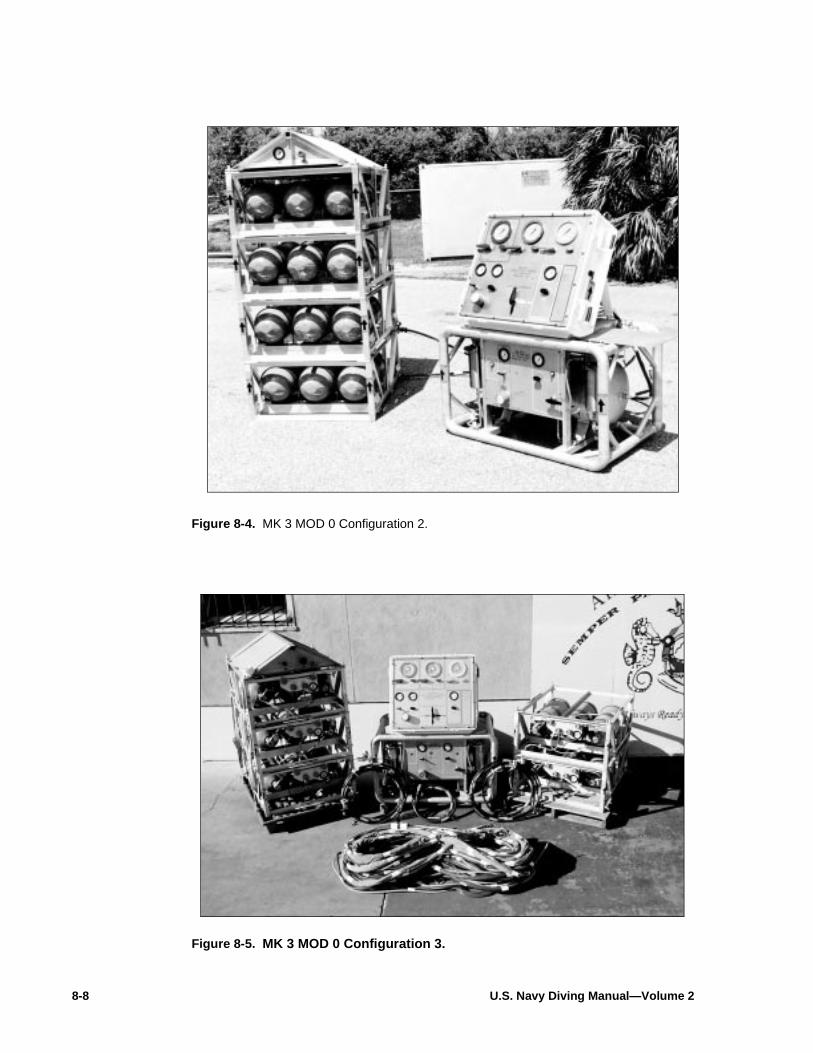
8-8 U.S. Navy Diving Manual—Volume 2
Figure 8-4. MK 3 MOD 0 Configuration 2.
Figure 8-5. MK 3 MOD 0 Configuration 3.

m,tionalm is
ply
ol
n
ec-cuba
pair
wstem
Change 1
8-4.3 ROPER Diving Cart. The ROPER diving cart is a trailer-mounted diving systedesigned to suport one working and one standby diver in underwater operatasks performed by Ship Repair Activities to 60 fsw (Figure 8-7). The systeself-contained, transportable, and certifiable in accordance with U.S. Navy Divingand Hyperbaric System Safety Certification Manual, NAVSEA SS521-AA-MAN-010. The major components/subsystems mounted within the cart body are:
� Diving control station . A single operator controls and monitors the air supand operates the communication system.
� Power distribution system . External power for communications and contrstation lighting.
� Intercommunication system (AC/DC) . Provides communications betweedivers and the diving control station.
� Air supply system . Primary air source of two 6 cu ft, 3,000 psi air flasks; sondary air source of a single 1.52 cu ft, 3,000 psi air flask; and a scharging station.
Detailed information and operating instructions are covered in Operations andMaintenance Instructions for Ready Operational Pierside Emergency Re(ROPER) Diving Cart, SS500-AS-MMA-010.
8-4.4 Flyaway Dive System (FADS) I. The FADS I is an air transportable, 0–190 fssystem that can be delivered to a suitable diving platform quickly. The sy
Figure 8-6. Flyaway Dive System (FADS) III.
CHAPTER 8 — Surface-Supplied Air Diving Operations 8-9

res-sentivingwith
TRand
era-
t-ment usempo-
ili-
consists of a filter control console (FCC) intended for use with the medium-psure flyaway air compressors and/or conventional air supplies. In its preconfiguration, the system can service up to four divers depending on the dequipment in use. MK 21 MOD 1 and MK 20 equipment may be employed the FADS I. See Figure 8-8.
Operational instructions for FADS I and II are covered in Fly Away Diving SystemFilter/Console Operation and Maintenance Instructions, S9592-AD-MMM.FLCONT CSL; Fly Away Diving System Compressor Model 5120 Operation Maintenance Instructions, S9592-AE-MMM-010/MOD 5120; and Fly AwayDiving System Diesel Driven Compressor Unit Ex 32 Mod 0, PN 5020559, Option and Maintenance Instructions, S9592-AC-MMM-010/Detroit DSL 3-53.
8-4.5 Flyaway Dive System (FADS) II. The FADS II is a self-supported, air transporable, 0–190 fsw air diving system, designed and packaged for rapid deployworldwide to a vessel of opportunity (see Figure 8-9). Primarily intended forin salvage or inspection and emergency ship repairs, the system’s main conents are:
� Diving outfit . Four demand helmet (MK 21 MOD 1) assemblies with umbcals, communication system, tool kit, and repair parts kit.
� Two medium-pressure air compressors (MPAC) . Diesel-driven QUINCY 250psi, 87 standard cubic feet per minute (scfm), skid mounted.
Figure 8-7. ROPER Cart.
8-10 U.S. Navy Diving Manual—Volume 2

P
,
m-
� High pressure air compressor (HPAC) . Diesel-driven INGERSOLL RAND10T2, 3,000 psi, 15 scfm, skid-mounted.
� Filter control console . Regulates and filters air from MPAC, HPAC, or Hbanks to support four divers, skid-mounted.
� Suitcase filter control console . Filters MPAC air to support three divers.
� Double-lock aluminum recompression chamber . Standard USN chamberskid-mounted and designed to interface with filter control console.
� Two HP air banks . Two sets of HP banks providing secondary diver and chaber air.
� HP oxygen tank . One bank of HP oxygen providing chamber support.
Figure 8-8. Flyaway Air Diving System (FADS) I.
CHAPTER 8 — Surface-Supplied Air Diving Operations 8-11

g,
a-
iv-
pportfoundtem
tions
d to pre-. In
Change 1
� 5 kW diesel generator . Provides power for communications, chamber lightinmiscellaneous.
� 5 kW diesel light tower . Provides power to tripod lights, mast lights, underwter lights.
� Hydraulic tool package and underwater lights . As required.
� Equipment shelter . Fiberglass container houses filter control console and ding station.
� Two conex boxes . Steel containers for equipments storage.
8-4.6 Flyaway Dive System (FADS) III.
The FADS III is a portable, self-contained, surface-supplied diverlife-support system designed tosupport dive missions to 190 fsw(Figure 8-9). Compressed air at5,000 psi is contained in nine 3.15cu ft floodable volume compositeflasks vertically mounted in an AirSupply Rack Assembly (ASRA).The ASRA will hold 9600 scf ofcompressed air at 5,000 psi.Compressed air is provided by a5,000 psi air compressor assemblywhich includes an air purificationsystem. The FADS III alsoincludes a control consoleassembly and a volume tankassembly. Three banks of two,three, and four flasks allow theASRA to provide primary and secondary air to the divers as well as air to suchamber operations. Set-up and operating procedures for the FADS III are in the Operating and Maintenance Technical Manual for Fly Away Dive Sys(FADS) III Air System, S9592-B1-MMO-010.
8-5 ACCESSORY EQUIPMENT FOR SURFACE-SUPPLIED DIVING
Accessory equipment that is often useful in surface-supplied diving operaincludes the following items:
� Lead Line . The lead line is used to measure depth.
� Descent Line . The descent line guides the diver to the bottom and is usepass tools and equipment. A 3-inch double-braid line is recommended, tovent twisting and to facilitate easy identification by the diver on the bottom
Figure 8-9. Air Supply Rack Assembly (ASRA) of FADS III.
8-12 U.S. Navy Diving Manual—Volume 2

CHAPTER 8 — Surface-Supplied Air Diving Operations 8-15
� Cooling . Cooling the air prior to expanding it raises its relative humidity, per-mitting some of the water to condense. The condensed liquid may then bedrained from the system.
8-6.1.5 Standby Diver Air Requirements. Air supply requirements cannot be based solelyon the calculated continuing needs of the divers who are initially engaged in theoperation. There must be an adequate reserve to support a standby diver shouldone be needed.
8-6.2 Primary and Secondary Air Supply. All surface-supplied diving systems mustinclude a primary and a secondary air supply in accordance with the U.S. NavyDiving and Manned Hyperbaric Systems Safety Certification Manual, SS521-AA-MAN-010. The primary supply must be able to support the air flow and pressurerequirements for the diving equipment designated (Table 8-1). The capacity of theprimary supply must meet the consumption rate of the designated number ofdivers for the full duration of the dive (bottom time plus decompression time). Themaximum depth of the dive, the number of divers, and the equipment to be usedmust be taken into account when sizing the supply. The secondary supply must besized to be able to support recovery of all divers using the equipment and diveprofile of the primary supply if the primary supply sustains a casualty at the worst-case time (for example, immediately prior to completion of planned bottom timeof maximum dive depth, when decompression obligation is greatest). Primary andsecondary supplies may be either high-pressure (HP) bank-supplied orcompressor-supplied.
8-6.2.1 Requirements for Operating Procedures and Emergency Procedures. Oper-ating procedures (OPs) and emergency procedures (EPs) must be available tosupport operation of the system and recovery from emergency situations. OPs andEPs are required to be NAVSEA or NAVFAC approved in accordance with para-graph 4-2.6.3. Should the surface-supplied diving system be integrated with arecompression chamber, an air supply allowance for chamber requirements(Volume 5) must be made.
All valves and electrical switches that directly influence the air supply shall belabeled:
Table 8-1. Primary Air System Requirements.
Air Consumption
System Minimum Manifold Pressure (MMP) Average Over Period of Dive (acfm)
MK 21 MOD 1 (Depth in fsw × 0.445) + 90 to 165 psi, depending on the depth of the dive
1.4 (Note 1)
MK 20 MOD 0 (Depth in fsw × 0.445) + 90 psi 1.4
Note 1:The manifold supply pressure requirement is 90 psig over-bottom pressure for depths to 60 fsw, and 135 psig over-bottom pressure for depths from 60-130 fsw. For dives from 131-190 fsw, 165 psi over-bottom pressure shall be used.
Change 1

8-16 U.S. Navy Diving Manual—Volume 2
“DIVER'S AIR SUPPLY - DO NOT TOUCH”
Banks of flasks and groups of valves require only one central label at the mainstop valve.
A volume tank must be part of the air supply system and be located between thesupply source and the diver’s manifold hose connection. This tank maintains theair supply should the primary supply source fail, providing time to actuate thesecondary air supply, and to attenuate the peak air flow demand.
8-6.2.2 Air Compressors. Many air supply systems used in Navy diving operationsinclude at least one air compressor as a source of air. To properly select such acompressor, it is essential that the diver have a basic understanding of the princi-ples of gas compression. The NAVSEA/00C ANU list contains guidance forNavy-approved compressors for divers’ air systems. See Figure 8-10.
8-6.2.2.1 Reciprocating Air Compressors. Reciprocating air compressors are the onlycompressors authorized for use in Navy air diving operations. Low-pressure (LP)models can provide rates of flow sufficient to support surface-supplied air divingor recompression chamber operations. High-pressure models can charge high-pressure air banks and scuba cylinders.
8-6.2.2.2 Compressor Capacity Requirements. Air compressors must meet the flow andpressure requirements outlined in paragraph 8-6.1.2 and 8-6.1.3. Normally, recip-rocating compressors have their rating (capacity in cubic feet per minute anddelivery pressure in psig) stamped on the manufacturer’s identification plate. Thisrating is usually based on inlet conditions of 70°F (21.1°C), 14.7 psia barometricpressure, and 36 percent relative humidity (an air density of 0.075 pound per cubicfoot). If inlet conditions vary, the actual capacity either increases or decreasesfrom rated values. If not provided directly, capacity will be provided byconducting a compressor output test (see Topside Tech Notes, Volume II Compres-sors/Process Instruction NAVSEA-00C4-PI-004, Compressor Capacity Testing).Since the capacity is the volume of air at defined atmospheric conditions,compressed per unit of time, it is affected only by the first stage, as all other stagesonly increase the pressure and reduce temperature. All industrial compressors arestamped with a code, consisting of at least two, but usually four to five, numbersthat specify the bore and stroke.
The actual capacity of the compressor will always be less than the displacementbecause of the clearance volume of the cylinders. This is the volume above thepiston that does not get displaced by the piston during compression. Compressorshaving a first-stage piston diameter of four inches or larger normally have anactual capacity of about 85 percent of their displacement. The smaller the first-stage piston, the lower the percentage capacity, because the clearance volumerepresents a greater percentage of the cylinder volume.
8-6.2.2.3 Lubrication. Reciprocating piston compressors are either oil lubricated or waterlubricated. The majority of the Navy’s diving compressors are lubricated by petro-leum or synthetic oil. In these compressors, the lubricant:
� Prevents wear between friction surfaces
Change 1

CHAPTER 9 — Air Decompression 9-3
9-3.7 Equivalent Single Dive Bottom Time. The equivalent single dive bottom time isthe time used to select a schedule for a single repetitive dive. This time isexpressed in minutes.
9-3.8 Unlimited/No-Decompression (No “D”) Limit. The maximum time that can bespent at a given depth that safe ascent can be made directly to the surface at aprescribed travel rate with no decompression stops is the unlimited/no-decompres-sion or No “D” limit (Table 9-6).
9-3.9 Repetitive Dive. A repetitive dive is any dive conducted within 12 hours of aprevious dive.
9-3.10 Repetitive Group Designation. The repetitive group designation is a letter used toindicate the amount of residual nitrogen remaining in a diver’s body following aprevious dive.
9-3.11 Residual Nitrogen. Residual nitrogen is the nitrogen gas still dissolved in adiver’s tissues after surfacing.
9-3.12 Residual Nitrogen Time. Residual nitrogen time is the time that must be added tothe bottom time of a repetitive dive to compensate for the nitrogen still in solutionin a diver’s tissues from a previous dive. Residual nitrogen time is expressed inminutes.
9-3.13 Single Dive. A single dive refers to any dive conducted more than 12 hours after aprevious dive.
9-3.14 Single Repetitive Dive. A single repetitive dive is a dive for which the bottomtime used to select the decompression schedule is the sum of the residual nitrogentime and the actual bottom time of the dive.
9-3.15 Surface Interval. The surface interval is the time a diver has spent on the surfacefollowing a dive. It begins as soon as the diver surfaces and ends as soon as hestarts his next descent.
9-4 DIVE RECORDING
Chapter 5 provides information for maintaining a Command Diving Log andpersonal diving log and reporting individual dives to the Naval Safety Center. Inaddition to these records, every Navy air dive may be recorded on a diving chartsimilar to Figure 9-1. The diving chart is a convenient means of collecting the divedata, which in turn will be transcribed in the dive log. Diving Record abbrevia-tions that may be used in the Command Diving Log are:
� LS - Left Surface
� RB - Reached Bottom
� LB - Left Bottom
Change 1

9-4 U.S. Navy Diving Manual—Volume 2
Figure 9-1. Air Diving Chart.

CHAPTER 9 — Air Decompression 9-63
Table 9-8. U.S. Navy Standard Air Decompression Table (Continued).
Bottomtime(min)
Timefirst stop (min:sec)
Decompression stops (feet/meters) Total decom-
pression time
(min:sec)
Depthfeet/meters
200
60.9
190
57.9
180
54.8
170
51.8
160
48.7
150
45.7
140
42.6
130
39.6
120
36.5
110
33.5
100
30.4
90
27.4
80
24.3
70
21.3
60
18.2
50
15.2
40
12.1
30
9.1
20
6.0
10
3.0
ExceptionalExposure
28085.3
5 8:40 2 2 13:2010 8:00 1 2 5 13 30:2015 7:40 1 3 4 11 26 54:2020 7:40 3 4 8 23 39 86:2025 7:20 2 5 7 16 23 56 118:2030 7:00 1 3 7 13 22 30 70 155:2040 6:40 1 6 6 13 17 27 51 93 223:20
ExceptionalExposure
29088.4
5 9:00 2 3 14:4010 8:20 1 3 5 16 34:4015 8:00 1 3 6 12 26 57:4020 8:00 3 7 9 23 43 94:4025 7:40 3 5 8 17 23 60 125:4030 7:20 1 5 6 16 22 36 72 167:4040 7:00 3 5 7 15 16 32 51 95 233:40
Bottomtime(min)
Timefirst stop (min:sec)
Decompression stops (feet/meters) Total decom-
pression time
(min:sec)Depth
feet/meters
200
60.9
190
57.9
180
54.8
170
51.8
160
48.7
150
45.7
140
42.6
130
39.6
120
36.5
110
33.5
100
30.4
90
27.4
80
24.3
70
21.3
60
18.2
50
15.2
40
12.1
30
9.1
20
6.0
10
3.0
ExceptionalExposure
30091.4
5 9:20 3 3 16:0010 8:40 1 3 6 17 37:0015 8:20 2 3 6 15 26 62:0020 8:00 2 3 7 10 23 47 102:0025 7:40 1 3 6 8 19 26 61 134:0030 7:40 2 5 7 17 22 39 75 177:0040 7:20 4 6 9 15 17 34 51 90 ‘236:0060 6:00 4 10 10 10 10 10 14 28 32 50 90 187 465:0090 4:40 ‘3 8 8 10 10 10 10 16 24 24 34 48 64 90 142 187 698:00
120 4:00 4 8 8 8 8 10 14 24 24 24 34 42 58 66 102 122 142 187 895:00180 3:30 6 8 8 8 14 20 21 21 28 40 40 48 56 82 98 100 114 122 142 187 1173:00

9-64 U.S. Navy Diving Manual—Volume 2
Table 9-9. Surface Decompression Table Using Oxygen.
Time (min) breathing airat water stops (feet/meters)
Bottomtime(min)
Time tofirst stop or
surface (min:sec)
Time at40-foot
chamber stop (min) on
oxygen Surface
Total decompression
time(min:sec)
Depthfeet/meters
60
18.2
50
15.2
40
12.1
30
9.1SurfaceInterval
7021.3
50 2:20 2:2090 2:20 15 22:40
120 2:20 23 30:40150 2:20 31 43:40180 2:20 39 51:40
8024.3
40 2:40 2:4070 2:40 14 22:0085 2:40 20 28:00
100 2:40 26 34:00115 2:40 31 44:00130 2:40 37 50:00150 2:40 44 57:00
9027.4
30 3:00 3:0060 3:00 14 22:2070 3:00 20 28:2080 3:00 25 33:2090 3:00 30 38:20
100 3:00 34 47:20110 3:00 39 52:20120 3:00 43 56:20130 3:00 48 61:20
10030.4
25 3:20 3:2050 3:20 14 22:4060 3:20 20 28:4070 3:20 26 34:4080 3:20 32 45:4090 3:20 38 51:40
100 3:20 44 57:40110 3:20 49 62:40120 2:20 3 53 69:20
11033.5
20 3:40 3:4040 3:40 12 21:0050 3:40 19 28:0060 3:40 26 35:0070 3:40 33 47:0080 2:40 1 40 55:0090 2:40 2 46 62:00
100 2:40 5 51 70:00110 2:40 54 80:00
TOTA
L TI
ME
FRO
M L
AST
WAT
ER S
TOP
TO F
IRST
CHA
MB
ER S
TOP
NOT
TO E
XCEE
D 5
MIN
UTES
1-M
INUT
E 20
SEC
ON
DS A
SCEN
T FR
OM
40
FEET
IN C
HAM
BER
TO
SU
RFAC
E
Change 1
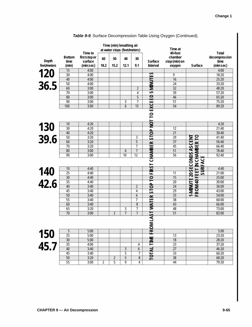
CHAPTER 9 — Air Decompression 9-65
Table 9-9 . Surface Decompression Table Using Oxygen (Continued).
Time (min) breathing airat water stops (feet/meters)
Bottomtime(min)
Time tofirst stop or
surface (min:sec)
Time at40-foot
chamber stop (min) on
oxygen Surface
Total decompression
time(min:sec)
Depthfeet/meters
60
18.2
50
15.2
40
12.1
30
9.1SurfaceInterval
12036.5
15 4:00 4:0030 4:00 9 18:2040 4:00 16 25:2050 4:00 24 33:2060 3:00 2 32 48:2070 3:00 4 39 57:2080 3:00 5 46 65:2090 3:00 3 7 51 75:20
100 3:00 6 15 54 89:20
13039.6
10 4:20 4:2030 4:20 12 21:4040 4:20 21 30:4050 3:20 3 29 41:4060 3:20 5 37 56:4070 3:20 7 45 66:4080 3:00 6 7 51 78:4090 3:00 10 12 56 92:40
14042.6
10 4:40 4:4025 4:40 11 21:0030 4:40 15 25:0035 4:40 20 30:0040 3:40 2 24 36:0045 3:40 4 29 43:0050 3:40 6 33 54:0055 3:40 7 38 60:0060 3:40 8 43 66:0065 3:20 3 7 48 73:0070 3:00 2 7 7 51 82:00
15045.7
5 5:00 5:0025 5:00 13 23:2030 5:00 18 28:2035 4:00 4 23 37:2040 3:40 3 6 27 46:2045 3:40 5 7 33 60:2050 3:20 2 5 8 38 68:2055 3:00 2 5 9 4 44 79:20
TOTA
L TI
ME
FRO
M L
AST
WAT
ER S
TOP
TO F
IRST
CHA
MB
ER S
TOP
NOT
TO E
XCEE
D 5
MIN
UTES
1-M
INUT
E 20
SEC
ON
DS A
SCEN
T FR
OM
40
FEET
IN C
HAM
BER
TO
SU
RFAC
E
Change 1

9-66 U.S. Navy Diving Manual—Volume 2
Table 9-9. Surface Decompression Table Using Oxygen (Continued).
Time (min) breathing airat water stops (feet/meters)
Bottomtime(min)
Time tofirst stop or
surface (min:sec)
Time at40-foot
chamber stop (min) on
oxygen Surface
Total decompression
time(min:sec)
Depthfeet/meters
60
18.2
50
15.2
40
12.1
30
9.1SurfaceInterval
16048.7
5 5:20 5:2020 5:20 11 21:4025 5:20 16 26:4030 4:20 2 21 33:4035 4:00 4 6 26 46:4040 3:40 3 5 8 32 63:4045 3:20 3 4 8 6 38 74:40
17051.8
5 5:40 5:4020 5:40 13 24:0025 5:40 19 30:0030 4:20 3 5 23 42:0035 4:00 4 4 7 29 55:0040 3:40 4 4 8 6 36 74:00
TOTA
L TI
ME
FRO
M L
AST
WAT
ER S
TOP
TO F
IRST
CHA
MB
ER S
TOP
NOT
TO E
XCEE
D 5
MIN
UTES
1-M
INUT
E 20
SEC
OND
S AS
CEN
T FR
OM
40
FEET
IN C
HAM
BER
TO
SURF
ACE
Change 1

CHAPTER 10 — Nitrogen-Oxygen Diving Operations 10-7
10-7 FLEET TRAINING FOR NITROX
A Master Diver shall conduct training for NITROX diving prior to conductingNITROX diving operations. Actual NITROX dives are not required for thistraining. The following are the minimum training topics to be covered:
� Pulmonary and CNS oxygen toxicity associated with NITROX diving.� EAD tables and their association with the Navy air tables.� Safe handling of NITROX mixtures.
NITROX Charging and Mixing Technicians must be trained on the followingtopics:
� Oxygen handling safety.� Oxygen analysis equipment.� NITROX mixing techniques.� NITROX cleaning requirements (MILSTD 1330 Series).
10-8 NITROX DIVING EQUIPMENT
NITROX diving can be performed using a variety of equipment that can be brokendown into two general categories: surface-supplied or closed- and open-circuitscuba. Closed-circuit scuba apparatus is discussed in Chapter 17.
10-8.1 Open-Circuit Scuba Systems. Open-circuit scuba systems for NITROX divingare identical to air scuba systems with one exception: the scuba bottles are filledwith NITROX (nitrogen-oxygen) rather than air. There are specific regulatorsauthorized for NITROX diving, which are identified on the ANU list. These regu-lators have been tested to confirm their compatibility with the higher oxygenpercentages encountered with NITROX diving.
10-8.1.1 Regulators. Scuba regulators designated for NITROX use should be cleaned tothe standards of MILSTD 1330. Once designated for NITROX use and cleaned,the regulators should be maintained to the level of cleanliness outlined in MIL-STD 1330.

10-8 U.S. Navy Diving Manual—Volume 2
10-8.1.2 Bottles. Scuba bottles designated foruse with NITROX should be oxygencleaned and maintained to that level.The bottles should have a NITROX la-bel in large yellow letters on a greenbackground. Once a bottle is cleanedand designated for NITROX diving, itshould not be used for any other type ofdiving (Figure 10-2).
10-8.2 General. All high-pressure flasks,scuba cylinders, and all high-pressureNITROX charging equipment thatcomes in contact with 100 percent oxy-gen during NITROX diving, mixing, orcharging evolutions must be cleanedand maintained for NITROX service inaccordance with the current MIL-STD-1330 series.
10-8.3 Surface-Supplied NITROX Diving. Surface-supplied NITROX diving systemsmust be modified to make them compatible with the higher percentage of oxygenfound in NITROX mixtures. A request to convert the system to NITROX must beforwarded to NAVSEA 00C for review and approval. The request must be accom-panied by the proposed changes to the Pre-survey Outline Booklet (PSOB)permitting system use with NITROX. Once the system is designated for NITROX,it shall be labeled NITROX with large yellow letters on a green background.MILSTD 1330.D outlines the cleanliness requirements to which a surface-supplied NITROX system must be maintained.
Once a system has been cleaned and designated for NITROX use, only air meetingthe requirements of Table 10-2 shall be used to charge the system gas flasks. Airdiving, using a NITROX designated system, is authorized if the air meets thepurity requirements of Table 10-2.
The EGS used in surface-supplied NITROX diving shall be filled with the samemixture that is being supplied to the diver ± 0.5 percent.
10-9 EQUIPMENT CLEANLINESS
Cleanliness and the procedures used to obtain cleanliness are a concern withNITROX systems. MILSTD 1330 is applicable to anything with an oxygen levelhigher than 25 percent by volume. Therefore, MILSTD 1330 must be followedwhen dealing with NITROX systems. Personnel involved in the maintenance andrepair of NITROX equipment shall complete an oxygen clean worker course, asdescribed in MILSTD 1330. Even with oxygen levels of 25 to 40 percent, there isstill a greater risk of fire than with compressed air. Materials that would notnormally burn in air may burn at these higher O2 levels. Normally combustible
Figure 10-2. NITROX Scuba Bottle Markings.
Change 1

CHAPTER 10 — Nitrogen-Oxygen Diving Operations 10-9
materials require less energy to ignite and will burn faster. The energy required forignition can come from different sources, for example adiabatic compression orparticle impact/spark. Another concern is that if improper cleaning agents orprocesses are used, the agents themselves can become fire or toxic hazards. It istherefore important to adhere to MILSTD 1330 to reduce the risk of damage orloss of equipment and injury or death of personnel.
10-10 BREATHING GAS PURITY
It is essential that all gases used in producing a NITROX mixture meet thebreathing gas purity standards for oxygen (Table 4-3) and nitrogen (Table 4-5). Ifair is to be used to produce a mixture, it must be compressed using an oil-freeNITROX-approved compressor or meet the purity requirements of oil-free air(Table 10-2). Prior to diving, all NITROX gases shall be analyzed using anapproved O2 analyzer accurate to within ± 0.5 percent.
10-11 NITROX MIXING
NITROX mixing can be accomplished by a variety of techniques to produce afinal predetermined nitrogen-oxygen mixture. The techniques for mixingNITROX are listed as follows:
1. Continuous Flow Mixing . There are two techniques for continuous flowmixing:
a. Mix-maker . A mix-maker uses a precalibrated mixing system that pro-portions the amount of each gas in the mixture as it is delivered to acommon mixing chamber. A mix-maker performs a series of functionsthat ensures accurate mixtures. The gases are regulated to the sametemperature and pressure before they are sent through precision meter-ing valves. The valves are precalibrated to provide the desired mixingpressure. The final mixture can be provided directly to the divers or becompressed using an oil-free compressor into storage banks.
b. Oxygen Induction . Oxygen induction uses a system where low pressureoxygen is delivered to the intake header of an oil-free compressor,where it is mixed with the air being drawn into the compressor. Oxygenflow is adjusted and the compressor output is monitored for oxygencontent. When the desired NITROX mixture is attained the gas isdiverted to the storage banks for diver use while being continuallymonitored for oxygen content (Figure 10-3).
2. Mixing by Partial Pressure . Partial pressure mixing techniques are similar tothose used in helium-oxygen mixed gas diving and are discussed in Chapter16.
Change 1

10-10 U.S. Navy Diving Manual—Volume 2
a. Partial Pressure Mixing with Air . Oil-free air can be used as a Nitrogensource for the partial pressure mixing of NITROX using the followingprocedures:
� Prior to charging air into a NITROX bottle, the NITROX mixingtechnician shall smell, taste, and feel the oil-free air coming fromthe compressor for signs of oil, mist, or particulates, or for anyunusual smell. If any signs of compressor malfunction are found,the system must not be used until a satisfactory air sample has beencompleted.
� Prior to charging with oxygen, to produce a NITROX mix, theNITROX-charging technician shall charge the bottle to at least 100psi with oil-free air. This will reduce the risk of adiabatic compres-sion temperature increase. Once 100 psi of oil-free air has beenadded to the charging vessel, the required amount of oxygen shouldthen be added. The remaining necessary amount of oil-free air canthen be safely charged into the bottle. The charging rate forNITROX mixing shall not exceed 200 psi per minute.
WARNING Mixin g contaminated or non-oil free air with 100% oxy gen can result in acatastrophic fire and explosion.
Figure 10-3. Nitrox O2 Injection System.

CHAPTER 10 — Nitrogen-Oxygen Diving Operations 10-11
� Compressed air for NITROX mixing shall meet the purity stan-dards for “Oil-Free Air,” (Table 10-2). All compressors producingair for NITROX mixing shall have a filtration system designed toproduce oil-free air that has been approved by NAVSEA 00C3. Inaddition, all compressors producing oil-free air for NITROXcharging shall have an air sample taken within 90 days prior to use.
3. Mixing Using a Membrane System . Membrane systems selectively separategas molecules of different sizes such as nitrogen or oxygen from the air. Byremoving the nitrogen from the air in a NITROX membrane system theoxygen percent is increased. The resulting mixture is NITROX. Air is fed intoan in-line filter canister system that removes hydrocarbons and othercontaminants. It is then passed into the membrane canister containingthousands of hollow membrane fibers. Oxygen permeates across themembrane at a controlled rate. The amount of nitrogen removed is determinedby a needle valve. Once the desired nitrogen-oxygen ratio is achieved, the gasis diverted through a NITROX-approved compressor and sent to the storagebanks (see Figure 10-4 and Figure 10-5). Membrane systems can alsoconcentrate CO2 and argon.
4. Mixing Using Molecular Sieves . Molecular sieves are columns of solid, highlyselective chemical absorbent which perform a similar function to membranesystems, and are used in a similar fashion. Molecular sieves have the addedadvantage of absorbing CO2 and moisture from the feed gas.
5. Purchasing Premixed NITROX . Purchasing premixed NITROX is anacceptable way of obtaining a NITROX mixture. When purchasing premixedNITROX it is requisite that the gases used in the mixture meet the minimumpurity standards for oxygen (Table 4-3) and nitrogen (Table 4-5).
Table 10-2. Oil-Free Air.
Constituent Specification
Oxygen (percent by volume) 20-22%
Carbon dioxide (by volume) 500 ppm (max)
Carbon monoxide (by volume) 2 ppm (max)
Total hydrocarbons [as Methane (CH4) by volume] 25 ppm (max)
Odor Not objectionable
Oil, mist, particulates 0.1 mg/m3 (max)
Separated Water None
Total Water 0.02 mg/1 (max)
Halogenated Compounds (by volume):
Solvents 0.2 ppm (max)
Change 1

10-12 U.S. Navy Diving Manual—Volume 2
10-12 NITROX MIXING, BLENDING, AND STORAGE SYSTEMS
Nitrox mixing, blending, and storage systems shall be designed for oxygen serviceand constructed using oxygen-compatible material following accepted militaryand commercial practices in accordance with either ASTM G-88, G-63, G-94, orMILSTD 438 and 777. Commands should contact NAVSEA 00C for specificguidance on developing NITROX mixing, blending, or storage systems.Commands are not authorized to build or use a NITROX system without priorNAVSEA 00C review and approval.
Figure 10-4. LP Air Supply NITROX Membrane Configuration.

CHAPTER 13 — Mixed-Gas Operational Planning 13-1
C H A P T E R 1 3
0L[HG�*DV�2SHUDWLRQDO�3ODQQLQJ
13-1 INTRODUCTION
13-1.1 Purpose. This chapter discusses the planning associated with mixed-gas divingoperations. Most of the provisions in Chapter 6, Operations Planning, also apply tomixed-gas operations and should be reviewed for planning. In planning anymixed-gas operation, the principles and techniques presented in this chapter shallbe followed.
13-1.2 Scope. This chapter outlines a comprehensive planning process that may be usedin whole or in part to effectively plan and execute diving operations in support ofmilitary operations.
13-1.3 Additional Sources of Information. This chapter is not the only source of infor-mation available to the diving team when planning mixed-gas diving operations.Operation and maintenance manuals for the diving equipment, intelligencereports, and oceanographic studies all contain valuable planning information. Thenature of the operation will dictate the procedures to be employed and the plan-ning and preparations required for each. While it is unlikely that even the bestplanned operation can ever anticipate all possible contingencies, attention to detailin planning will minimize complications that could threaten the success of amission.
13-1.4 Complexity of Mixed-Gas Diving. Mixed-gas diving operations are complex,requiring constant support and close coordination among all personnel. Due toextended decompression obligations, mixed-gas diving can be hazardous if notproperly planned and executed. Seemingly minor problems can quickly escalateinto emergency situations, leaving limited time to research dive protocols or oper-ational orders to resolve the situation. Each member of the diving team must bequalified on his watch station and be thoroughly competent in executing appli-cable operating and emergency procedures. Safety is important in any divingoperation and must become an integral part of all operations planning.
13-1.5 Medical Considerations. The Diving Officer, Master Diver, and Diving Super-visor must plan the operation to safeguard the physical and mental well-being ofeach diver. All members of the team must thoroughly understand the medicalaspects of mixed-gas, oxygen, and saturation diving. A valuable source of guid-ance in operations planning is the Diving Medical Officer (DMO), a physiciantrained specifically in diving medicine and physiology.
Mixed-gas diving entails additional risks and procedural requirements for thediver and the support team. At the surface, breathing a medium other than aircauses physiological changes in the body. When a diver breathes an unusualmedium under increased pressure, additional alterations in the functioning of themind and body may occur. Each diver must be aware of the changes that can occur
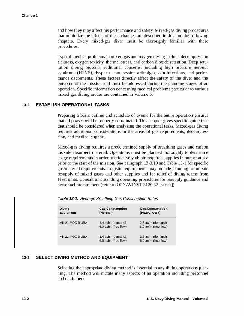
13-2 U.S. Navy Diving Manual—Volume 3
and how they may affect his performance and safety. Mixed-gas diving proceduresthat minimize the effects of these changes are described in this and the followingchapters. Every mixed-gas diver must be thoroughly familiar with theseprocedures.
Typical medical problems in mixed-gas and oxygen diving include decompressionsickness, oxygen toxicity, thermal stress, and carbon dioxide retention. Deep satu-ration diving presents additional concerns, including high pressure nervoussyndrome (HPNS), dyspnea, compression arthralgia, skin infections, and perfor-mance decrements. These factors directly affect the safety of the diver and theoutcome of the mission and must be addressed during the planning stages of anoperation. Specific information concerning medical problems particular to variousmixed-gas diving modes are contained in Volume 5.
13-2 ESTABLISH OPERATIONAL TASKS
Preparing a basic outline and schedule of events for the entire operation ensuresthat all phases will be properly coordinated. This chapter gives specific guidelinesthat should be considered when analyzing the operational tasks. Mixed-gas divingrequires additional considerations in the areas of gas requirements, decompres-sion, and medical support.
Mixed-gas diving requires a predetermined supply of breathing gases and carbondioxide absorbent material. Operations must be planned thoroughly to determineusage requirements in order to effectively obtain required supplies in port or at seaprior to the start of the mission. See paragraph 13-3.10 and Table 13-1 for specificgas/material requirements. Logistic requirements may include planning for on-siteresupply of mixed gases and other supplies and for relief of diving teams fromFleet units. Consult unit standing operating procedures for resupply guidance andpersonnel procurement (refer to OPNAVINST 3120.32 [series]).
13-3 SELECT DIVING METHOD AND EQUIPMENT
Selecting the appropriate diving method is essential to any diving operations plan-ning. The method will dictate many aspects of an operation including personneland equipment.
Table 13-1. Average Breathing Gas Consumption Rates.
Diving Equipment
Gas Consumption(Normal)
Gas Consumption(Heavy Work)
MK 21 MOD 0 UBA 1.4 acfm (demand) 6.0 acfm (free flow)
2.5 acfm (demand) 6.0 acfm (free flow)
MK 22 MOD 0 UBA 1.4 acfm (demand) 6.0 acfm (free flow)
2.5 acfm (demand) 6.0 acfm (free flow)
Change 1

CHAPTER 14 — Surface-Supplied Mixed-Gas Diving Procedures 14-1
C H A P T E R 1 4
6XUIDFH�6XSSOLHG�0L[HG�*DV
'LYLQJ�3URFHGXUHV
14-1 INTRODUCTION
14-1.1 Purpose. The purpose of this chapter is to familiarize divers with U.S. Navysurface-supplied procedures.
14-1.2 Scope. Surface-supplied mixed-gas diving is conducted with helium-oxygenmixtures supplied from the surface by a flexible hose. Surface-supplied mixed-gasdiving is particularly suited for operations beyond the depth limits of air diving,yet short of the depths and times requiring the use of a deep diving system.Surface-supplied mixed-gas diving is also useful in the deep air diving range whenfreedom from nitrogen narcosis is required.
14-2 PLANNING THE OPERATION
Planning surface-supplied mixed-gas dives involves many of the same consider-ations used when planning an air dive. Planning aspects that are unique to surface-supplied mixed-gas diving include the logistics of providing several different gasmixtures to the diver and the limitations on the duration of carbon dioxide absorp-tion canisters in cold water.
14-2.1 Depth and Exposure Time. The normal operational limit for surface-suppliedmixed-gas diving is 300 fsw. Within each decompression table (Table 14-7),exceptional-exposure dives are enclosed in red boxes to separate them fromnormal working dives. Exceptional-exposure dives require lengthy decompressionand are associated with an increased risk of decompression sickness and exposureto the elements. Exceptional exposures should be undertaken only in emergencycircumstances. Planned exceptional-exposure dives require prior CNO approval.Repetitive diving is not allowed in surface-supplied helium-oxygen diving.
14-2.2 Water Temperature. Loss of body temperature (hypothermia) can be a majorproblem during long, deep dives. Because the high thermal conductivity of heliumin a dry suit accelerates the loss of body heat, a hot water suit is preferred forsurface-supplied dives when using the MK 21 MOD 1 in very cold water.
Refer to Chapter 3 for more information on thermal problems and the signs andsymptoms of hypothermia. Refer to Chapter 11 for information on ice and coldwater diving operations.
14-2.3 Gas Mixtures. Air, 100 percent oxygen, and several helium-oxygen mixtures willbe required to dive the surface-supplied mixed-gas tables over their full range. Thelogistics of supplying these gases must be carefully planned. Analysis of the
14-2 U.S. Navy Diving Manual—Volume 3
oxygen content of helium-oxygen mixtures shall be accurate to within ±0.5percent.
14-2.3.1 Maximum/Minimum Mixtures. For each depth in the decompression tables, theallowable maximum and minimum oxygen percentage in the helium-oxygenmixture used on the bottom is specified. For operations planning, the range ofpossible depths should be established and a mixture selected that will meet themaximum/minimum specification across the depth range. The maximum oxygenconcentration has been selected so that the diver never exceeds an oxygen partialpressure of 1.3 ata while on the bottom. The minimum oxygen percentage allowedin the mixture is 16 percent for depths to 200 fsw, 12 percent for depths from 200fsw to 300 fsw, and 10 percent for depths in excess of 300 fsw. Diving with amixture near maximum oxygen percentage is encouraged as it offers a decompres-sion advantage to the diver.
14-2.3.1.1 On the Surface. On the surface, the diver’s gas mixture must contain a minimumof 16 percent oxygen. When a bottom mix with less than 16 percent oxygen is tobe used, a shift to the bottom mix is made at 20 fsw during descent (see paragraph14-3.2).
14-2.3.1.2 Deeper than 200 fsw. For dives deeper than 200 fsw in which the bottom mixturecontains less than 16 percent oxygen, a gas shift from the bottom mix to a 60percent helium/40 percent oxygen mixture is required at the 100-fsw decompres-sion stop or the next shallower stop if there is no 100-fsw stop (see paragraph14-3.3).
14-2.3.1.3 Up to 200 fsw. For dives to 200 fsw and shallower or for deeper dives in whichthe bottom mixture contains more than 16 percent oxygen, a shift to 60 percenthelium/40 percent oxygen is not required but can be executed to increase decom-pression safety if desired.
14-2.3.1.4 Exceptional Exposure Dives. For exceptional-exposure dives, a shift to a 60percent helium/40 percent oxygen mixture is required at the 100-fsw stop or thenext shallower stop if there is no 100-fsw stop.
On all dives, a shift to 100 percent oxygen is made at the 50-fsw or 40-fsw waterstop if there is no 50-fsw stop.
14-2.3.2 Emergency Gas Supply. All divers are equipped with an emergency gas supply(EGS). The EGS gas mixture will be the same as the bottom mixture unless thebottom mixture contains less than 16 percent oxygen, in which case the EGS gasmixture will be 16 + 0.5 percent oxygen and the balance will be helium. The EGSbottle shall be a minimum of steel 72 charged to 1,800 psig or aluminum 80charged to 1,900 psig.
14-3 SURFACE-SUPPLIED HELIUM-OXYGEN DESCENT AND ASCENT PROCEDURES
The Surface-Supplied Helium-Oxygen Decompression Table (Table 14-7) is usedto decompress divers from surface-supplied helium-oxygen dives. The table is in adepth-time format similar to the U.S. Navy Air Decompression Table and is used
Change 1

CHAPTER 15 — Saturation Diving 15-19
15-15.1 UBA Gas. An adequate quantity of gas within an oxygen partial pressure range of0.44–1.25 ata shall be available for use.
15-15.2 Emergency Gas. Emergency gas is used as a backup breathing supply in the eventof DDC or PTC atmosphere contamination. An emergency gas with an oxygenpartial pressure of 0.16 to 1.25 ata shall be immediately available to the built-inbreathing system (BIBS). The volume of emergency breathing gas shall be suffi-cient to supply the divers for the time needed to correct the DDC atmosphere.
Upward excursions of the PTC or DDC or decompression shall not be startedduring emergency gas breathing unless the oxygen partial pressure of the diver’sinspired gas is 0.42 ata or above.
Example. An emergency gas schedule for a dive to 850 fsw is:
15-15.3 Treatment Gases. . Treatment gases having an oxygen partial pressure range of1.5 to 2.8 shall be available in the event of decompression sickness. The premixedgases shown in Table 15-4 may be used over the depth range of 0 – 1,600 fsw. Asource of treatment gas shall be available as soon as treatment depth is reached.The source shall be able to supply a sufficient volume of breathing gas to treateach chamber occupant.
15-16 ENVIRONMENTAL CONTROL
Helium-oxygen gas mixtures conduct heat away from the diver very rapidly. As aresult, temperatures higher than those required in an air environment are necessaryto keep a diver comfortable. As depth increases, the temperature necessary toachieve comfort may increase to the 85–93°F range.
Bank Mix#1 84/16 HeO2#2 96/4 HeO2
Allowable Depth Range (fsw)0–22499–998
Shift Depth (fsw)200
Table 15-4. Treatment Gases.
Depth (fsw) Mix
0–60 100% O2
60–100 40/60% HeO2
100–200 64/36% HeO2
200–350 79/21% HeO2
350–600 87/13% HeO2
600–1000 92/08% HeO2
1000–1600 95/05% HeO2
Change 1

15-20 U.S. Navy Diving Manual—Volume 3
As a general guideline to achieve optimum comfort for all divers, the temperatureshould be kept low enough for the warmest diver to be comfortable. Cooler diverscan add clothing as needed. All divers should be questioned frequently about theircomfort.
The relative humidity should be maintained between 30 and 80 percent with 50 to70 percent being the most desirable range for diver comfort, carbon dioxidescrubber performance, and fire protection.
15-17 FIRE ZONE CONSIDERATIONS
Every effort shall be made to eliminate any fire hazard within a chamber. Whenoxygen percentages are elevated as during the later stages of decompression, a firewill burn rapidly once started, perhaps uncontrollably. As a result, special precau-tions are necessary to protect the diver’s safety when in the fire zone. The fire zoneis where the oxygen concentration in the chamber is 6 percent or greater. Usingstandard saturation diving procedures (oxygen partial pressure between 0.44 and0.48 ata), fire is possible at depths less than 231 fsw. Thus, during a saturation divethe divers will be in the fire zone during initial compression to depth and duringthe final stages of decompression.
Example. The chamber atmosphere is 0.48 ata ppO2. The minimum oxygenpercentage for combustion is 6 percent. Compute the fire zone depth.
The fire zone depth is computed as follows:
Although the design of the DDS minimizes fire potential, personnel must remainvigilant at all times to prevent fires. Appropriate precautions for fire preventioninclude:
� Fire-suppression systems, if available, must be operational at all times when inthe fire zone.
� Chamber clothing, bed linen, and towels shall be made of 100% cotton. Diverswim trunks made of a 65% polyester–35% cotton material is acceptable.
� Mattresses and pillows shall be made of fire-retardant material when in the firezone.
� Limit combustible personal effects to essential items.
� Limit reading material, notebooks, etc., in the fire zone.
Fire zone depth (fsw)ppO2 33×O2%/100------------------------- 33–=
0.48 33×0.06
---------------------- 33–=
231 fsw=

CHAPTER 15 — Saturation Diving 15-33
is activated, all divers shall immediately go on BIBS. Watchstanders shouldmonitor depth carefully because an extensive fire will cause an increase in depth.If the fire suppression system fails to extinguish the fire, rapid compression of thechamber with helium may extinguish the fire, in that helium lowers the oxygenconcentration and promotes heat transfer. After the fire is extinguished, chamberatmosphere contaminant emergency procedures shall be followed.
15-22.4 PTC Emergencies. PTC emergencies, like DDC emergencies, require specific,timely, and uniform responses in order to prevent injury or casualty to divers,watchstanders, and equipment.
15-23 SATURATION DECOMPRESSION
Saturation decompression may be initiated by an upward excursion as long as theexcursion remains within the limits permitted by the Unlimited Duration Excur-sion Tables. The alternative is to begin travel at the appropriate decompressionrate without the upward excursion. Decompression travel rates are found on Table15-9.
15-23.1 Upward Excursion Depth. The minimum depth to which the upward excursionmay be made is found by entering Table 15-8 with the deepest depth attained byany diver in the preceding 48 hours. The total upward excursion actually chosen isdetermined by the Diving Officer and Master Diver, and approved by theCommanding Officer, taking into consideration environmental factors, the diver’sworkload, and the diver’s physical condition.
15-23.2 Travel Rate. The travel rate for the upward excursion is 2 fsw/min. Beginningdecompression with an upward excursion will save considerable time and may beused whenever practical.
15-23.3 Post-Excursion Hold. Due to the increased risk of decompression sicknessfollowing an upward excursion for dives with a storage depth of 200 fsw or less, a2-hour post-excursion hold should be utilized. The 2-hour hold begins upon arrivalat upward excursion depth.
15-23.4 Rest Stops. During decompression, traveling stops for a total of 8 hours out ofevery 24 hours. The 8 hours should be divided into at least two periods known as
Table 15-9. Saturation Decompression Rates.
Depth Rate
1,600 – 200 fsw 6 feet per hour
200 – 100 fsw 5 feet per hour
100 – 50 fsw 4 feet per hour
50 – 0 fsw 3 feet per hour
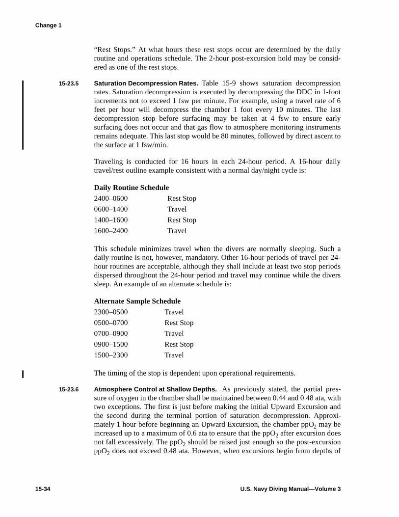
15-34 U.S. Navy Diving Manual—Volume 3
“Rest Stops.” At what hours these rest stops occur are determined by the dailyroutine and operations schedule. The 2-hour post-excursion hold may be consid-ered as one of the rest stops.
15-23.5 Saturation Decompression Rates. Table 15-9 shows saturation decompressionrates. Saturation decompression is executed by decompressing the DDC in 1-footincrements not to exceed 1 fsw per minute. For example, using a travel rate of 6feet per hour will decompress the chamber 1 foot every 10 minutes. The lastdecompression stop before surfacing may be taken at 4 fsw to ensure earlysurfacing does not occur and that gas flow to atmosphere monitoring instrumentsremains adequate. This last stop would be 80 minutes, followed by direct ascent tothe surface at 1 fsw/min.
Traveling is conducted for 16 hours in each 24-hour period. A 16-hour dailytravel/rest outline example consistent with a normal day/night cycle is:
This schedule minimizes travel when the divers are normally sleeping. Such adaily routine is not, however, mandatory. Other 16-hour periods of travel per 24-hour routines are acceptable, although they shall include at least two stop periodsdispersed throughout the 24-hour period and travel may continue while the diverssleep. An example of an alternate schedule is:
The timing of the stop is dependent upon operational requirements.
15-23.6 Atmosphere Control at Shallow Depths. As previously stated, the partial pres-sure of oxygen in the chamber shall be maintained between 0.44 and 0.48 ata, withtwo exceptions. The first is just before making the initial Upward Excursion andthe second during the terminal portion of saturation decompression. Approxi-mately 1 hour before beginning an Upward Excursion, the chamber ppO2 may beincreased up to a maximum of 0.6 ata to ensure that the ppO2 after excursion doesnot fall excessively. The ppO2 should be raised just enough so the post-excursionppO2 does not exceed 0.48 ata. However, when excursions begin from depths of
Daily Routine Schedule
2400–0600 Rest Stop
0600–1400 Travel
1400–1600 Rest Stop
1600–2400 Travel
Alternate Sample Schedule
2300–0500 Travel
0500–0700 Rest Stop
0700–0900 Travel
0900–1500 Rest Stop
1500–2300 Travel
Change 1
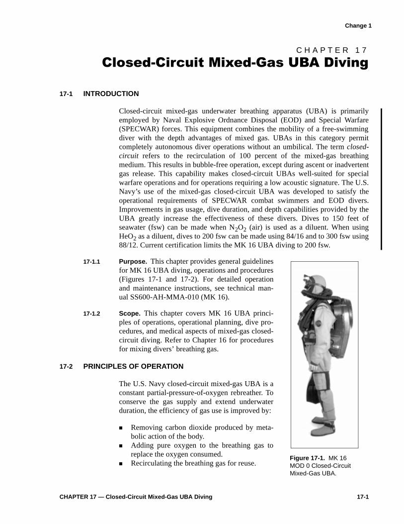
CHAPTER 17 — Closed-Circuit Mixed-Gas UBA Diving 17-1
C H A P T E R 1 7
&ORVHG�&LUFXLW�0L[HG�*DV�8%$�'LYLQJ
17-1 INTRODUCTION
Closed-circuit mixed-gas underwater breathing apparatus (UBA) is primarilyemployed by Naval Explosive Ordnance Disposal (EOD) and Special Warfare(SPECWAR) forces. This equipment combines the mobility of a free-swimmingdiver with the depth advantages of mixed gas. UBAs in this category permitcompletely autonomous diver operations without an umbilical. The term closed-circuit refers to the recirculation of 100 percent of the mixed-gas breathingmedium. This results in bubble-free operation, except during ascent or inadvertentgas release. This capability makes closed-circuit UBAs well-suited for specialwarfare operations and for operations requiring a low acoustic signature. The U.S.Navy’s use of the mixed-gas closed-circuit UBA was developed to satisfy theoperational requirements of SPECWAR combat swimmers and EOD divers.Improvements in gas usage, dive duration, and depth capabilities provided by theUBA greatly increase the effectiveness of these divers. Dives to 150 feet ofseawater (fsw) can be made when N2O2 (air) is used as a diluent. When usingHeO2 as a diluent, dives to 200 fsw can be made using 84/16 and to 300 fsw using88/12. Current certification limits the MK 16 UBA diving to 200 fsw.
17-1.1 Purpose. This chapter provides general guidelinesfor MK 16 UBA diving, operations and procedures(Figures 17-1 and 17-2). For detailed operationand maintenance instructions, see technical man-ual SS600-AH-MMA-010 (MK 16).
17-1.2 Scope. This chapter covers MK 16 UBA princi-ples of operations, operational planning, dive pro-cedures, and medical aspects of mixed-gas closed-circuit diving. Refer to Chapter 16 for proceduresfor mixing divers’ breathing gas.
17-2 PRINCIPLES OF OPERATION
The U.S. Navy closed-circuit mixed-gas UBA is aconstant partial-pressure-of-oxygen rebreather. Toconserve the gas supply and extend underwaterduration, the efficiency of gas use is improved by:
� Removing carbon dioxide produced by meta-bolic action of the body.
� Adding pure oxygen to the breathing gas toreplace the oxygen consumed.
� Recirculating the breathing gas for reuse. Figure 17-1. MK 16 MOD 0 Closed-Circuit Mixed-Gas UBA.
Change 1

17-2 U.S. Navy Diving Manual—Volume 4
17-2.1 Recirculation and Carbon Dioxide Removal. The diver’s breathing medium isrecirculated in a closed-circuit UBA to remove carbon dioxide and permit reuse ofthe inert diluent and unused oxygen in the mixture. The basic recirculation systemconsists of a closed loop that incorporates inhalation and exhalation hoses andassociated check valves, a mouthpiece or full face mask (FFM), a carbon dioxideremoval unit, and a diaphram assembly.
17-2.1.1 Recirculating Gas. Recirculating gas is normally moved through the circuit bythe natural inhalation-exhalation action of the diver’s lungs. Because the lungs canproduce only small pressure differences, the entire circuit must be designed forminimum flow restriction.
17-2.1.2 Full Face Mask. The FFM uses an integral oral-nasal mask or T-bit to reduce deadspace and the possibility of rebreathing carbon dioxide-rich gas. Similarly, checkvalves used to ensure one-way flow of gas through the circuit must be close to thediver’s mouth and nose to minimize dead space. All breathing hoses in the system
Figure 17-2. MK 16 MOD 0 UBA Functional Block Diagram.

CHAPTER 17 — Closed-Circuit Mixed-Gas UBA Diving 17-9
requiring a deep operational capability should allow frequent opportunity fortraining, ensuring diver familiarity with equipment and procedures. Workupdives are strongly recommended prior to diving at depths greater than 130fsw. MK 16 diver qualifications may be obtained only by completion of the MK16 Basic Course (A-431-0075) or the Naval Special Warfare Center MK 16 quali-fications course. MK 16 qualifications remain in effect as long as diverqualifications are maintained in accordance with Military Personnel Manualarticle 1410380. However, a diver who has not made a MK 16 dive in the previoussix months must refamiliarize himself with MK 16 EPs and OPs and mustcomplete a MK 16 training dive prior to making a MK 16 operational dive. Priorto conducting MK 16 decompression diving, a diver who has not conducted aMK 16 decompression dive within the previous six months must complete openwater decompression training dives. Refer to Table 17-1 for the personnel require-ments for MK 16 diving operations.
17-4.1 Operating Limitations. Using combat swimmer multilevel dive (CSMD) proce-dures provides SPECWAR divers with the option of conducting multiple-depthdiving with the MK 16 UBA if a maximum depth of 70 fsw (NEDU Report 13-83)is not exceeded at any time during the dive. Refer to Table 17-2 for equipmentdepth limitations. Diving Supervisors must also consider the limiting factorspresented in the following paragraphs when planning closed-circuit UBAoperations.
17-4.1.1 Oxygen Flask Endurance. In calculating the endurance of the MK 16, only theoxygen flask is considered. The endurance of the oxygen flask is dependent uponthe following:
� Flask floodable volume
Figure 17-4. Underwater Breathing Apparatus MK 16 MOD 0.
Change 1

17-10 U.S. Navy Diving Manual—Volume 4
� Initial predive pressure� Required reserve pressure
Table 17-1. Personnel Requirements Chart for Mixed-Gas Diving.
Mixed-Gas UBA Dive Team
Optimum Minimum
Designation One Diver Two Divers One Diver Two Divers
Diving Officer (Notes 3, 4) (Notes 3, 4) (Notes 3, 4) (Notes 3, 4)
Diving Medical Officer (Note 5) (Note 5) (Note 5) (Note 5)
Diving Supervisor 1 1 1 (Note 2) 1 (Note 2)
Diver 1 2 1 2
Standby Diver 1 (Note 7) 1 (Note 7) 1 (Note 7) 1 (Note 7)
Diver Tender 1 (Note 1) 2 (Note 1) 1 (Note 1) 1 (Note 1)
Standby Diver Tender 1 1 (Note 8) (Note 8)
Timekeeper/Recorder 1 1
EBS Operator (Note 6) (Note 6) (Note 6) (Note 6)
Total Personnel Required 6 8 4 5
Notes :
1. One tender per diver when divers are surface tended. If using a buddy line, one tender is required for each buddy pair.
2. May act as timekeeper/recorder.
3. EOD Diving Officer is required on site for all EOD operations that involve render safe procedure; for SPECWAR, Diving Officer is not required on station. On station is defined as at the dive location.
4. Diving Officer may perform any other function simultaneously (i.e., Diving Officer/Diver).
5. A Diving Medical Officer is required on station for all dives exceeding the normal working limit.
6. EBS Operator is for MK 16 in-water decompression dives.
7. At the Diving Supervisor’s discretion, the standby diver shall be fully dressed with the exception of scuba or MK 16, mask, and fins. These items shall be ready to don.
8. If the Standby Diver is deployed, the Diving Supervisor shall tend the Standby Diver.
Table 17-2. Equipment Operational Characteristics.
DivingEquipment
Maximum Working Limit (fsw)(Notes 1 and 2)
ChamberRequirement
MK 16 UBA 150 (air diluent)200 (HeO2 diluent)
Note 3Note 3
Notes :
1. Depth limits are based on considerations of working time, decompression obligation, oxygen tolerance and nitrogen narcosis. The expected duration of the gas supply, the expected duration of the carbon dioxide absorbent, the adequacy of thermal protection, or other factors may also limit both the depth and the duration of the dive.
2. A Diving Medical Officer is required on station for all dives exceeding the normal working limit.
3. Dives deeper than the normal working limits require a recompression chamber on station. On station is defined as at the dive location.
Change 1

CHAPTER 17 — Closed-Circuit Mixed-Gas UBA Diving 17-15
lazy-shot lines. Lines shall be marked with red and yellow or black bands startingat the diver(s) or clump end. Red bands will indicate 50 feet and yellow or blackbands will mark every 10 feet.
17-4.2.5 Diver Marker Buoy. Diver marker buoys will be constructed to provide adequatevisual reference to monitor the divers location. Additionally, the amount of linewill be of sufficient length for the planned dive profile.
17-4.2.6 Depth Gauge/Wrist Watch. A single depth gauge and wrist watch may be usedwhen diving with a partner and using a distance line.
17-4.3 Recompression Chamber Considerations. A recompression chamber and aDiving Medical Officer are not required on station (on station is defined as at thedive location) as prerequisites for closed-circuit UBA diving operations, unless thedive(s) will exceed the maximim working limit. However, the following itemsshould be determined prior to beginning diving operations:
� Location of the nearest functional recompression chamber. Positive confirma-tion of the chamber’s availability in case of emergency should be obtained.
� Location of the nearest available Diving Medical Officer if not at the nearestrecompression chamber.
� Location of the nearest medical facility for treatment of injuries and medicalproblems not requiring recompression therapy.
� The optimal method of transportation to the treatment chamber or medicalfacility. If coordination with other units for aircraft/boat/vehicle support isnecessary, the Diving Supervisor shall know the telephone numbers and pointsof contact necessary to make these facilities available as quickly as possible incase of emergency. A medical evacuation plan should be included in the Div-ing Supervisor brief. Preparing an emergency assistance checklist similar tothat in Chapter 6 is recommended.
17-4.4 Diving Procedures for MK 16.
17-4.4.1 Employing a Single, Untended EOD Diver. Generally, it is safer for divers towork in pairs rather than singly. However, to do so when diving on underwaterinfluence ordnance doubles the diver bottom time expended, increases the risk tolife from live ordnance detonation, and increases the risk of detonation caused bythe additional influence signature of the second diver. The EOD Diving Officermay authorize the employment of a single, untended diver when it is deemed thatthe ordnance hazard is greater than the hazard presented by diving alone. Allsingle, untended divers must use a full face mask (FFM). The EOD Diving Officeror Diving Supervisor shall consider the following factors when deciding whetherto operate singly or in pairs:
� Experience of the diver� Confidence of the team
Change 1

17-16 U.S. Navy Diving Manual—Volume 4
� Type and condition of ordnance suspected� Environmental conditions� Degree of operational urgency required
17-4.4.2 Simulated Training Scenarios. Simulated ordnance training scenarios do notconstitute a real threat, therefore single untended divers shall not be used intraining operations. The diver shall be surface tended or marked by attaching abuoy to him.
17-4.4.3 EOD Standard Safety Procedures. The following standard safety proceduresshall be observed during EOD diving operations:
� An EOD Diving Officer shall be on scene during all phases of an explosiveordnance disposal diving operation involving a Render Safe Procedure (RSP).
� When diving on unknown or influence ordnance, the standby diver’s equip-ment shall be the same type as the diver neutralizing the ordnance.
17-4.4.4 Diving Methods. Diving methods include:
� Single Marked Diving . Consists of a single diver with FFM marked with alightweight buoyant line attached to a surface float. Upon completion of a diverequiring decompression, the diver will signal the diving supervisor that he isready to surface. The diving boat will then approach the surface float andrecover the diver.
� Paired Marked Diving . Procedures for paired marked diving are identical tothe procedures for a single marked diver, but with the addition of the seconddiver connected by a buddy/distance line.

CHAPTER 17 — Closed-Circuit Mixed-Gas UBA Diving 17-21
at the setpoint during normal activity at a constant depth (the oxygen-additionvalve operation on the MK 16 cannot be heard).
� Secondary Display . Check the secondary display frequently (every 2-3 min-utes) as outlined in the MK 16 O&M manual (paragraph 3-4.6.2) to ensure thatall sensors are consistent with the primary display and that plus and minus bat-tery voltages are properly indicating.
� High-Pressure Indicators . Check the oxygen- and diluent-pressure indicatorsfrequently as outlined in the MK 16 O&M manual (paragraph 3-4.6.3) toensure that the gas supply is adequate to complete the dive.
17-8 ASCENT PROCEDURES
The maximum ascent rate for the MK 16 is 30 feet per minute. During ascent,when water pressure decreases, the diaphragm dump valve compensates forincreased gas volume by discharging the excess gas into the water. As a result,oxygen in the breathing gas mixture may be vented faster than O2 is replaced bythe addition valve. In this case, the primary display may alternate red/green beforethe low-ppO2 signal (blinking red) appears. This is a normal transition period andshall not cause concern. Monitor the secondary display frequently on ascent andadd oxygen by depressing the bypass valve during this instance.
17-9 POSTDIVE PROCEDURES
Postdive procedures shall be completed in accordance with the appropriate post-dive checklists in the MK 16 UBA O&M manual.
17-10 DECOMPRESSION PROCEDURES
When diving with an open-circuit UBA, ppO2 increases with depth. With a closed-circuit UBA, ppO2 remains constant at a preset level regardless of depth. There-fore, standard U.S. Navy decompression tables cannot be used.
17-10.1 Use of Constant ppO 2 Decompression Tables. Closed-circuit UBA users mustuse constant ppO2 decompression tables Oxygen in Nitrogen (air diluent), andOxygen in Helium (Helium-Oxygen diluent). Closed-circuit, mixed-gas UBAdecompression tables (Table 17-14 and Table 17-15) are included at the end of thischapter.
17-10.2 Monitoring ppO 2. During decompression, it is very important to frequentlymonitor the secondary display and ensure a 0.7 ppO2 is maintained as closely aspossible. Always use the appropriate decompression table when surfacing, even ifUBA malfunction has significantly altered the ppO2.
NOTE Surface decompression is not authorized for MK 16 operations.Appropriate surface decompression tables have not been developed forconstant 0.7 ata ppO 2 closed-circuit divin g.
Change 1

17-22 U.S. Navy Diving Manual—Volume 4
17-10.3 Rules for Using 0.7 ata Constant ppO 2 in Nitrogen and in Helium Decompression Tables.
NOTE The rules usin g the 0.7 ata ppO 2 tables are the same for nitro gen andhelium; however, the tables are not interchan geable.
� These tables are designed to be used with MK 16 UBA (or any other constantppO2 closed-circuit UBA) with an oxygen setpoint of 0.7 ata or higher.
� When using helium as the inert gas, the amount of nitrogen must be minimizedin the breathing loop. Flush the UBA well with helium-oxygen using properpurge procedure in the MK 16 UBA O&M manual.
� Tables are grouped by depth and within each depth group is a limit line. Thesetables are designed to be dived to the limit line. Schedules below the limit lineprovide for unforeseen circumstances when a diver might experience an inad-vertent downward excursion or for an unforeseen reason overstay the plannedbottom time.
� Tables/schedules are selected according to the maximum depth obtained dur-ing the dive and the bottom time (time from leaving the surface to leaving thebottom).
� General rules for using these tables are the same as for standard air tables:
1. Enter the table at the listed depth that is exactly equal to or is next greaterthan the maximum depth attained during the dive.
2. Select the bottom time from those listed for the selected depth that isexactly equal to or is next greater than the bottom time of the dive.
3. Never attempt to interpolate between decompression schedules.
4. Use the decompression stops listed for the selected bottom time.
5. Ensure that the diver's chest is maintained as close as possible to eachdecompression depth for the number of minutes listed.
6. Maximum ascent rate is 30 feet per minute.
7. Begin timing each stop on arrival at the decompression stop depth andresume ascent when the specified time has elapsed. Do not include ascenttime as part of stop time.
8. The last stop may be taken at 20 fsw if desired. After completing theprescribed 20-fsw stop, remain at any depth between 10 fsw and 20 fswinclusive for the 10-fsw stop time as noted in the appropriatedecompression table.

CHAPTER 17 — Closed-Circuit Mixed-Gas UBA Diving 17-23
9. Always use the appropriate decompression table when surfacing even ifUBA malfunction has significantly altered ppO2.
� In emergency situations (e.g., UBA flood-out or failure), immediately ascendto the first decompression stop according to the original decompression sched-ule if deeper than the first stop, and shift to the Emergency Breathing System(EBS). The subsequent decompression is modified according to the diluent gasoriginally breathed.
— Helium-Oxygen Diluent . Follow the original HeO2 decompressionschedule without modification while breathing air.
— Nitrogen-Oxygen (Air) Diluent . Double all remaining decompressionstops while breathing air. If the switch to emergency air is made whileat a decompression stop, then double the remaining time at that stopand all shallower stops. If the dive falls within the no-demompressionlimit and a switch to EBS has occurred, a mandatory 10-minute stopat 20 fsw is required.
If either of these procedures is used, the diver should be closely observed forsigns of decompression sickness for 2 hours following the dive, but need not betreated unless symptoms arise.
� When selecting the proper decompression table, all dives within the past 12hours must be considered. Repetitive dives are allowed. Repetitive divingdecompression procedures vary depending on the breathing medium(s)selected for past dives and for the current dive. If a dive resulted in breathingfrom the EBS then no repetitive dives shall be made within the next 12 hours.Refer to the following tables:
— Table 17-8a for Repetitive Dive Procedures for Various Gas Medi-ums.
— Figure 17-1 for the Dive Worksheet for Repetitive 0.7 ata ConstantPartial Pressure Oxygen in Nitrogen Dives.
— Table 17-9 for the No-Decompression Limits and Repetitive GroupDesignation Table for No-Decompression 0.7 ata Constant PartialPressure Oxygen in Nitrogen Dives.
— Table 17-10 for the Residual Nitrogen Timetable for Repetitive 0.7ata Constant Partial Pressure Oxygen in Nitrogen Dives.
17-10.4 PPO2 Variances. The ppO2 in the MK 16 UBAs is expected to vary slightly from0.6 - 0.9 ata for irregular brief intervals. This does not constitute a malfunction.The decompression tables were calculated and tested using functioning or proto-type MK 16 UBAs. When addition of oxygen to the UBA is manually controlled,
Change 1

17-24 U.S. Navy Diving Manual—Volume 4
Table 17-8a. Repetitive Dive Procedures for Various Gas Mediums.
WARNINGNo repetitive dives are authorized after an
emergency procedure requirin g a shift to the EBS.
Selection of Repetitive Procedures for Various Gas Mediums
Previous Breathing Medium(Refer to Notes 1, 2, and 3) Current Breathing Medium Procedure from Table 17-8b
N2O2 N2O2 A
Air N2O2 B
N2O2 Air C
HeO2 HeO2 D
HeO2 Air E
Air HeO2 F
HeO2 N2O2 G
N2O2 HeO2 H
Notes:
1. If a breathing medium containing helium was breathed at any time during the 12-hour period immediately preceding a dive, use HeO2 as the previous breathing medium.
2. If 100 percent oxygen rebreathers are used on a dive in conjunction with other breathing gases, treat that portion of the dive as if 0.7 ATA O2 in N2 was breathed.
3. If both air and 0.7 ATA O2 in N2 are breathed during a dive, treat the entire dive as an air dive. If the 0.7 ata O2 in N2 is breathed at depths 80 fsw or deeper, add the following correction factors to the maximum depth when selecting the appropriate air table.
Maximum Depth on N 2O2 Correction Factor
Not exceeding 80 FSW 0
81-99 Plus 5
100-119 Plus 10
120-139 Plus 15
140-150 Plus 20
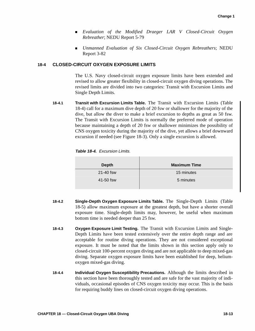
CHAPTER 18 — Closed-Circuit Oxygen UBA Diving 18-13
� Evaluation of the Modified Draeger LAR V Closed-Circuit OxygenRebreather; NEDU Report 5-79
� Unmanned Evaluation of Six Closed-Circuit Oxygen Rebreathers; NEDUReport 3-82
18-4 CLOSED-CIRCUIT OXYGEN EXPOSURE LIMITS
The U.S. Navy closed-circuit oxygen exposure limits have been extended andrevised to allow greater flexibility in closed-circuit oxygen diving operations. Therevised limits are divided into two categories: Transit with Excursion Limits andSingle Depth Limits.
18-4.1 Transit with Excursion Limits Table. The Transit with Excursion Limits (Table18-4) call for a maximum dive depth of 20 fsw or shallower for the majority of thedive, but allow the diver to make a brief excursion to depths as great as 50 fsw.The Transit with Excursion Limits is normally the preferred mode of operationbecause maintaining a depth of 20 fsw or shallower minimizes the possibility ofCNS oxygen toxicity during the majority of the dive, yet allows a brief downwardexcursion if needed (see Figure 18-3). Only a single excursion is allowed.
18-4.2 Single-Depth Oxygen Exposure Limits Table. The Single-Depth Limits (Table18-5) allow maximum exposure at the greatest depth, but have a shorter overallexposure time. Single-depth limits may, however, be useful when maximumbottom time is needed deeper than 25 fsw.
18-4.3 Oxygen Exposure Limit Testing. The Transit with Excursion Limits and Single-Depth Limits have been tested extensively over the entire depth range and areacceptable for routine diving operations. They are not considered exceptionalexposure. It must be noted that the limits shown in this section apply only toclosed-circuit 100-percent oxygen diving and are not applicable to deep mixed-gasdiving. Separate oxygen exposure limits have been established for deep, helium-oxygen mixed-gas diving.
18-4.4 Individual Oxygen Susceptibility Precautions. Although the limits described inthis section have been thoroughly tested and are safe for the vast majority of indi-viduals, occasional episodes of CNS oxygen toxicity may occur. This is the basisfor requiring buddy lines on closed-circuit oxygen diving operations.
Table 18-4. Excursion Limits.
Depth Maximum Time
21-40 fsw 15 minutes
41-50 fsw 5 minutes
Change 1

18-14 U.S. Navy Diving Manual—Volume 4
18-4.5 Transit with Excursion Limits. A 20 foot maximum depth for transit with oneexcursion, if necessary, will be the preferred option in most combat swimmeroperations. When operational considerations necessitate a descent to deeper than20 fsw for longer than allowed by the excursion limits, the appropriate single-depth limit should be used (paragraph 18-4.6).
18-4.5.1 Transit with Excursion Limits Definitions. The following definitions are illus-trated in Figure 18-3:
� Transit is the portion of the dive spent at 20 fsw or shallower.
� Excursion is the portion of the dive deeper than 20 fsw.
� Excursion time is the time between the diver’s initial descent below 20 fswand his return to 20 fsw or shallower at the end of the excursion.
Figure 18-3. Example of Transit with Excursion.
Table 18-5. Single-Depth Oxygen Exposure Limits.
Depth Maximum Oxygen Time
25 fsw 240 minutes
30 fsw 80 minutes
35 fsw 25 minutes
40 fsw 15 minutes
50 fsw 10 minutes
Change 1

CHAPTER 18 — Closed-Circuit Oxygen UBA Diving 18-15
� Oxygen time is calculated as the time interval between when the diver beginsbreathing from the closed-circuit oxygen UBA (on-oxygen time) and the timewhen he discontinues breathing from the closed-circuit oxygen UBA (off-oxy-gen time).
18-4.5.2 Transit with Excursion Rules. A diver who has maintained a transit depth of 20fsw or shallower may make one brief downward excursion as long as he observesthese rules:
� Maximum total time of dive (oxygen time) may not exceed 240 minutes.
� A single excursion may be taken at any time during the dive.
� The diver must have returned to 20 fsw or shallower by the end of the pre-scribed excursion limit.
� The time limit for the excursion is determined by the maximum depth attainedduring the excursion (Table 18-4). Note that the Excursion Limits are differentfrom the Single-Depth Limits.
Example: Dive Profile Using Transit with Excursion Limits. A dive mission callsfor a swim pair to transit at 15 fsw for 45 minutes, descend to 36 fsw, andcomplete their objective. As long as the divers do not exceed a maximum depth of40 fsw, they may use the 40-fsw excursion limit of 15 minutes. The time at whichthey initially descend below 20 fsw to the time at which they finish the excursionmust be 15 minutes or less.
18-4.5.3 Inadvertent Excursions. If an inadvertent excursion should occur, one of thefollowing situations will apply:
� If the depth and/or time of the excursion exceeds the limits in Table 18-4 or ifan excursion has been taken previously, the dive must be aborted and the divermust return to the surface.
� If the excursion was within the allowed excursion limits, the dive may be con-tinued to the maximum allowed oxygen dive time, but no additionalexcursions deeper than 25 fsw may be taken.
� The dive may be treated as a single-depth dive applying the maximum depthand the total oxygen time to the Single-Depth Limits shown in Table 18-5.
Example 1. A dive pair is having difficulty with a malfunctioning compass. Theyhave been on oxygen (oxygen time) for 35 minutes when they notice that theirdepth gauge reads 55 fsw. Because this exceeds the maximum allowed oxygenexposure depth, the dive must be aborted and the divers must return to the surface.
Example 2. A diver on a compass swim notes that his depth gauge reads 32 fsw.He recalls checking his watch 5 minutes earlier and at that time his depth gaugeread 18 fsw. As his excursion time is less than 15 minutes, he has not exceeded the
Change 1
18-16 U.S. Navy Diving Manual—Volume 4
excursion limit for 40 fsw. He may continue the dive, but he must maintain hisdepth at 25 fsw or less and make no additional excursions.
NOTE If the diver is unsure how lon g he was below 20 fsw, the dive must beaborted.
18-4.6 Single-Depth Limits. The term Single-Depth Limits does not mean that the entiredive must be spent at one depth, but refers to the time limit applied to the divebased on the maximum depth attained during the dive.
18-4.6.1 Single-Depth Limits Definitions. The following definitions apply when using theSingle-Depth Limits:
� Oxygen time is calculated as the time interval between when the diver beginsbreathing from the closed-circuit oxygen UBA (on-oxygen time) and the timewhen he discontinues breathing from the closed-circuit oxygen UBA (off-oxy-gen time).
� The depth for the dive used to determine the allowable exposure time is deter-mined by the maximum depth attained during the dive. For intermediate depth,the next deeper depth limit will be used.
18-4.6.2 Depth/Time Limits. The Single-Depth Limits are provided in Table 18-5. Noexcursions are allowed when using these limits.
Example. Twenty-two minutes (oxygen time) into a compass swim, a dive pairdescends to 28 fsw to avoid the propeller of a passing boat. They remain at thisdepth for 8 minutes. They now have two choices for calculating their allowedoxygen time: (1) they may return to 25 fsw or shallower and use the time below 25fsw as an excursion, allowing them to continue their dive on the Transit withExcursion Limits to a maximum time of 240 minutes; or (2) they may elect toremain at 28 fsw and use the 30-fsw Single-Depth Limits to a maximum dive timeof 80 minutes.
18-4.7 Exposure Limits for Successive Oxygen Dives. If an oxygen dive is conductedafter a previous closed-circuit oxygen exposure, the effect of the previous dive onthe exposure limit for the subsequent dive is dependent on the Off-OxygenInterval.
18-4.7.1 Definitions for Successive Oxygen Dives. The following definitions apply whenusing oxygen exposure limits for successive oxygen dives.
� Off-Oxygen Interval. The interval between off-oxygen time and on-oxygentime is defined as the time from when the diver discontinues breathing fromhis closed-circuit oxygen UBA on one dive until he begins breathing from theUBA on the next dive.
Change 1

Table of Contents–Volume 5 5-v
Chap/Para Page
21-5.2 Recompression Treatments When Oxygen Is Not Available. . . . . . . . . . . . . 21-12
21-5.2.1 Descent/Ascent Rates for Air Treatment Tables. . . . . . . . . . . . .21-12
21-5.3 Treatment at Altitude . . . . . . . . . . . . . . . . . . . . . . . . . . . . . . . . . . . . . . . . . . . 21-12
21-5.4 Recompression Treatments When Oxygen Is Available. . . . . . . . . . . . . . . . 21-12
21-5.4.1 Treatment Table 5. . . . . . . . . . . . . . . . . . . . . . . . . . . . . . . . . . . .21-1221-5.4.2 Treatment Table 6. . . . . . . . . . . . . . . . . . . . . . . . . . . . . . . . . . . .21-1321-5.4.3 Treatment Table 6A . . . . . . . . . . . . . . . . . . . . . . . . . . . . . . . . . .21-1421-5.4.4 Treatment Table 4. . . . . . . . . . . . . . . . . . . . . . . . . . . . . . . . . . . .21-1421-5.4.5 Treatment Table 7. . . . . . . . . . . . . . . . . . . . . . . . . . . . . . . . . . . .21-1521-5.4.6 Treatment Table 8. . . . . . . . . . . . . . . . . . . . . . . . . . . . . . . . . . . .21-1721-5.4.7 Treatment Table 9. . . . . . . . . . . . . . . . . . . . . . . . . . . . . . . . . . . .21-18
21-5.5 Tending the Patient. . . . . . . . . . . . . . . . . . . . . . . . . . . . . . . . . . . . . . . . . . . . 21-18
21-5.5.1 DMO or DMT Inside Tender.. . . . . . . . . . . . . . . . . . . . . . . . . . . .21-1821-5.5.2 Use of DMO. . . . . . . . . . . . . . . . . . . . . . . . . . . . . . . . . . . . . . . . .21-1821-5.5.2a Non-Diver Inside Tender - Medical . . . . . . . . . . . . . . . . . . . . . . 21-1821-5.5.2b Emergency Management . . . . . . . . . . . . . . . . . . . . . . . . . . . . . 21-1821-5.5.3 Patient Positioning. . . . . . . . . . . . . . . . . . . . . . . . . . . . . . . . . . . .21-1921-5.5.4 Equalizing During Descent.. . . . . . . . . . . . . . . . . . . . . . . . . . . . .21-1921-5.5.5 Inside Tender Responsibilities. . . . . . . . . . . . . . . . . . . . . . . . . . .21-1921-5.5.6 Oxygen Breathing and Toxicity During Treatments. . . . . . . . . . .21-1921-5.5.7 Ancillary Care and Adjunctive Treatments. . . . . . . . . . . . . . . . . .21-2021-5.5.8 Sleeping and Eating. . . . . . . . . . . . . . . . . . . . . . . . . . . . . . . . . . .21-21
21-5.6 Recompression Chamber Life-Support Considerations. . . . . . . . . . . . . . . . . 21-21
21-5.6.1 Minimum Manning Requirements . . . . . . . . . . . . . . . . . . . . . . . .21-2221-5.6.2 Optimum Manning Requirements . . . . . . . . . . . . . . . . . . . . . . . .21-2221-5.6.3 Oxygen Control. . . . . . . . . . . . . . . . . . . . . . . . . . . . . . . . . . . . . .21-2221-5.6.4 Carbon Dioxide Control. . . . . . . . . . . . . . . . . . . . . . . . . . . . . . . .21-2321-5.6.5 Temperature Control. . . . . . . . . . . . . . . . . . . . . . . . . . . . . . . . . .21-2321-5.6.6 Chamber Ventilation.. . . . . . . . . . . . . . . . . . . . . . . . . . . . . . . . . .21-2421-5.6.7 Access to Chamber Occupants. . . . . . . . . . . . . . . . . . . . . . . . . .21-2521-5.6.8 Inside Tenders. . . . . . . . . . . . . . . . . . . . . . . . . . . . . . . . . . . . . . .21-25
21-5.7 Loss of Oxygen During Treatment. . . . . . . . . . . . . . . . . . . . . . . . . . . . . . . . . 21-26
21-5.7.1 Compensation. . . . . . . . . . . . . . . . . . . . . . . . . . . . . . . . . . . . . . .21-2621-5.7.2 Switching to Air Treatment Table. . . . . . . . . . . . . . . . . . . . . . . . .21-26
21-5.8 Use of High-Oxygen Mixes. . . . . . . . . . . . . . . . . . . . . . . . . . . . . . . . . . . . . . . 21-26
21-5.9 Treatment at Altitude - Tender Considerations . . . . . . . . . . . . . . . . . . . . . . . 21-27
21-6 POST-TREATMENT CONSIDERATIONS . . . . . . . . . . . . . . . . . . . . . . . . . . . . . . . . . . . 21-28
21-6.1 Post-Treatment Observation Period. . . . . . . . . . . . . . . . . . . . . . . . . . . . . . . . 21-28
21-6.2 Post-Treatment Transfer. . . . . . . . . . . . . . . . . . . . . . . . . . . . . . . . . . . . . . . . 21-28
21-6.3 Inside Tenders. . . . . . . . . . . . . . . . . . . . . . . . . . . . . . . . . . . . . . . . . . . . . . . . 21-28
21-6.4 Flying After Treatments. . . . . . . . . . . . . . . . . . . . . . . . . . . . . . . . . . . . . . . . . 21-28
21-6.4.1 Emergency Air Evacuation.. . . . . . . . . . . . . . . . . . . . . . . . . . . . .21-2821-6.4.2 Tender Surface Interval. . . . . . . . . . . . . . . . . . . . . . . . . . . . . . . .21-29
21-6.5 Treatment of Residual Symptoms. . . . . . . . . . . . . . . . . . . . . . . . . . . . . . . . . 21-29
21-6.5.1 Additional Recompression Treatments. . . . . . . . . . . . . . . . . . . .21-29
Change 1

5-vi U.S. Navy Diving Manual—Volume 5
Chap/Para Page
21-6.6 Returning to Diving after Treatment Table 5. . . . . . . . . . . . . . . . . . . . . . . . . 21-29
21-6.6.1 Returning to Diving After Treatment Table 6. . . . . . . . . . . . . . . .21-2921-6.6.2 Returning to Diving After Treatment Table 4 or 7. . . . . . . . . . . .21-30
21-7 NON-STANDARD TREATMENTS . . . . . . . . . . . . . . . . . . . . . . . . . . . . . . . . . . . . . . . . . 21-30
21-8 RECOMPRESSION TREATMENT ABORT PROCEDURES . . . . . . . . . . . . . . . . . . . . 21-30
21-8.1 Death During Treatment.. . . . . . . . . . . . . . . . . . . . . . . . . . . . . . . . . . . . . . . . 21-30
21-8.2 Oxygen Breathing Periods During Abort Procedure.. . . . . . . . . . . . . . . . . . . 21-30
21-8.3 Impending Natural Disasters or Mechanical Failures.. . . . . . . . . . . . . . . . . . 21-30
21-9 EMERGENCY MEDICAL EQUIPMENT . . . . . . . . . . . . . . . . . . . . . . . . . . . . . . . . . . . . 21-31
21-9.1 Primary Emergency Kit.. . . . . . . . . . . . . . . . . . . . . . . . . . . . . . . . . . . . . . . . . 21-31
21-9.2 Emergency Kits. . . . . . . . . . . . . . . . . . . . . . . . . . . . . . . . . . . . . . . . . . . . . . . 21-31
21-9.2.1 Primary Emergency Kit. . . . . . . . . . . . . . . . . . . . . . . . . . . . . . . .21-3121-9.2.2 Secondary Emergency Kit. . . . . . . . . . . . . . . . . . . . . . . . . . . . . .21-3121-9.2.3 Portable Monitor-Defibrillator. . . . . . . . . . . . . . . . . . . . . . . . . . . .21-32
21-9.3 Use of Emergency Kits.. . . . . . . . . . . . . . . . . . . . . . . . . . . . . . . . . . . . . . . . . 21-32
21-9.3.1 Modification of Emergency Kits. . . . . . . . . . . . . . . . . . . . . . . . . .21-32
22 RECOMPRESSION CHAMBER OPERATION
22-1 INTRODUCTION . . . . . . . . . . . . . . . . . . . . . . . . . . . . . . . . . . . . . . . . . . . . . . . . . . . . . . . 22-1
22-1.1 Purpose. . . . . . . . . . . . . . . . . . . . . . . . . . . . . . . . . . . . . . . . . . . . . . . . . . . . . . 22-1
22-1.2 Scope. . . . . . . . . . . . . . . . . . . . . . . . . . . . . . . . . . . . . . . . . . . . . . . . . . . . . . . . 22-1
22-2 DESCRIPTION. . . . . . . . . . . . . . . . . . . . . . . . . . . . . . . . . . . . . . . . . . . . . . . . . . . . . . . . . 22-1
22-2.1 Basic Requirements . . . . . . . . . . . . . . . . . . . . . . . . . . . . . . . . . . . . . . . . . . . . 22-1
22-2.1.1 Chamber Volume.. . . . . . . . . . . . . . . . . . . . . . . . . . . . . . . . . . . . .22-6
22-2.2 Modernized Chamber . . . . . . . . . . . . . . . . . . . . . . . . . . . . . . . . . . . . . . . . . . . 22-6
22-2.3 Transportable Recompression Chamber System (TRCS) . . . . . . . . . . . . . . . 22-6
22-2.4 Fly Away Recompression Chamber (FARCC). . . . . . . . . . . . . . . . . . . . . . . . . 22-6
22-2.5 Standard Features. . . . . . . . . . . . . . . . . . . . . . . . . . . . . . . . . . . . . . . . . . . . . . 22-7
22-2.5.1 Labeling. . . . . . . . . . . . . . . . . . . . . . . . . . . . . . . . . . . . . . . . . . . . .22-822-2.5.2 Inlet and Exhaust Ports. . . . . . . . . . . . . . . . . . . . . . . . . . . . . . . . .22-922-2.5.3 Pressure Gauges.. . . . . . . . . . . . . . . . . . . . . . . . . . . . . . . . . . . . .22-922-2.5.4 Relief Valves. . . . . . . . . . . . . . . . . . . . . . . . . . . . . . . . . . . . . . . . .22-922-2.5.5 Communications System. . . . . . . . . . . . . . . . . . . . . . . . . . . . . . . .22-922-2.5.6 Lighting Fixtures. . . . . . . . . . . . . . . . . . . . . . . . . . . . . . . . . . . . . .22-9
22-3 STATE OF READINESS . . . . . . . . . . . . . . . . . . . . . . . . . . . . . . . . . . . . . . . . . . . . . . . . 22-10
22-4 GAS SUPPLY . . . . . . . . . . . . . . . . . . . . . . . . . . . . . . . . . . . . . . . . . . . . . . . . . . . . . . . . 22-10
22-4.1 Capacity. . . . . . . . . . . . . . . . . . . . . . . . . . . . . . . . . . . . . . . . . . . . . . . . . . . . . 22-11
Change 1

Table of Contents–Volume 5 5-vii
Chap/Para Page
22-5 OPERATION . . . . . . . . . . . . . . . . . . . . . . . . . . . . . . . . . . . . . . . . . . . . . . . . . . . . . . . . . . 22-12
22-5.1 Predive Checklist . . . . . . . . . . . . . . . . . . . . . . . . . . . . . . . . . . . . . . . . . . . . . . 22-12
22-5.2 Safety Precautions . . . . . . . . . . . . . . . . . . . . . . . . . . . . . . . . . . . . . . . . . . . . 22-12
22-5.3 General Operating Procedures . . . . . . . . . . . . . . . . . . . . . . . . . . . . . . . . . . . 22-15
22-5.3.1 Tender Change-Out. . . . . . . . . . . . . . . . . . . . . . . . . . . . . . . . . . .22-1522-5.3.2 Lock-In Operations.. . . . . . . . . . . . . . . . . . . . . . . . . . . . . . . . . . .22-1522-5.3.3 Lock-Out Operations. . . . . . . . . . . . . . . . . . . . . . . . . . . . . . . . . .22-1522-5.3.4 Gag Valves.. . . . . . . . . . . . . . . . . . . . . . . . . . . . . . . . . . . . . . . . .22-15
22-5.4 Ventilation . . . . . . . . . . . . . . . . . . . . . . . . . . . . . . . . . . . . . . . . . . . . . . . . . . . 22-16
22-5.4.1 Chamber Ventilation Bill . . . . . . . . . . . . . . . . . . . . . . . . . . . . . . .22-1622-5.4.2 Notes on Chamber Ventilation. . . . . . . . . . . . . . . . . . . . . . . . . . .22-18
22-6 CHAMBER MAINTENANCE . . . . . . . . . . . . . . . . . . . . . . . . . . . . . . . . . . . . . . . . . . . . . 22-19
22-6.1 Postdive Checklist . . . . . . . . . . . . . . . . . . . . . . . . . . . . . . . . . . . . . . . . . . . . . 22-19
22-6.2 Scheduled Maintenance . . . . . . . . . . . . . . . . . . . . . . . . . . . . . . . . . . . . . . . . 22-19
22-6.2.1 Inspections. . . . . . . . . . . . . . . . . . . . . . . . . . . . . . . . . . . . . . . . . .22-1922-6.2.2 Corrosion. . . . . . . . . . . . . . . . . . . . . . . . . . . . . . . . . . . . . . . . . ..22-1922-6.2.3 Painting Steel Chambers. . . . . . . . . . . . . . . . . . . . . . . . . . . . . . .22-1922-6.2.4 Recompression Chamber Paint Process Instruction. . . . . . . . . .22-2122-6.2.5 Aluminum Chambers. . . . . . . . . . . . . . . . . . . . . . . . . . . . . . . . . .22-2522-6.2.6 Fire Hazard Prevention. . . . . . . . . . . . . . . . . . . . . . . . . . . . . . . .22-25
22-7 DIVER CANDIDATE PRESSURE TEST . . . . . . . . . . . . . . . . . . . . . . . . . . . . . . . . . . . . 22-26
22-7.1 Candidate Requirements. . . . . . . . . . . . . . . . . . . . . . . . . . . . . . . . . . . . . . . . 22-26
22-7.2 Procedure. . . . . . . . . . . . . . . . . . . . . . . . . . . . . . . . . . . . . . . . . . . . . . . . . . . . 22-26
22-7.2.1 References.. . . . . . . . . . . . . . . . . . . . . . . . . . . . . . . . . . . . . . . . .22-26
5A NEUROLOGICAL EXAMINATION
5A-1 INTRODUCTION . . . . . . . . . . . . . . . . . . . . . . . . . . . . . . . . . . . . . . . . . . . . . . . . . . . . . . . 5A-1
5A-2 INITIAL ASSESSMENT OF DIVING INJURIES . . . . . . . . . . . . . . . . . . . . . . . . . . . . . . . 5A-1
5A-3 NEUROLOGICAL ASSESSMENT . . . . . . . . . . . . . . . . . . . . . . . . . . . . . . . . . . . . . . . . . . 5A-2
5A-3.1 Mental Status. . . . . . . . . . . . . . . . . . . . . . . . . . . . . . . . . . . . . . . . . . . . . . . . . . 5A-5
5A-3.2 Coordination (Cerebellar/Inner Ear Function) . . . . . . . . . . . . . . . . . . . . . . . . . 5A-5
5A-3.3 Cranial Nerves. . . . . . . . . . . . . . . . . . . . . . . . . . . . . . . . . . . . . . . . . . . . . . . . . 5A-6
5A-3.4 Motor. . . . . . . . . . . . . . . . . . . . . . . . . . . . . . . . . . . . . . . . . . . . . . . . . . . . . . . . 5A-7
5A-3.4.1 Extremity Strength. . . . . . . . . . . . . . . . . . . . . . . . . . . . . . . . . . . .5A-85A-3.4.2 Muscle Size. . . . . . . . . . . . . . . . . . . . . . . . . . . . . . . . . . . . . . . . .5A-85A-3.4.3 Muscle Tone.. . . . . . . . . . . . . . . . . . . . . . . . . . . . . . . . . . . . . . . .5A-85A-3.4.4 Involuntary Movements. . . . . . . . . . . . . . . . . . . . . . . . . . . . . . . .5A-8
5A-3.5 Sensory Function. . . . . . . . . . . . . . . . . . . . . . . . . . . . . . . . . . . . . . . . . . . . . . . 5A-8
5A-3.5.1 Sensory Examination. . . . . . . . . . . . . . . . . . . . . . . . . . . . . . . . .5A-105A-3.5.2 Sensations . . . . . . . . . . . . . . . . . . . . . . . . . . . . . . . . . . . . . . . .5A-10
Change 1
5-viii U.S. Navy Diving Manual—Volume 5
Chap/Para Page
5A-3.5.3 Instruments. . . . . . . . . . . . . . . . . . . . . . . . . . . . . . . . . . . . . . . ..5A-105A-3.5.4 Testing the Trunk. . . . . . . . . . . . . . . . . . . . . . . . . . . . . . . . . . . ..5A-105A-3.5.5 Testing Limbs. . . . . . . . . . . . . . . . . . . . . . . . . . . . . . . . . . . . . ..5A-105A-3.5.6 Testing the Hands. . . . . . . . . . . . . . . . . . . . . . . . . . . . . . . . . . ..5A-105A-3.5.7 Marking Abnormalities. . . . . . . . . . . . . . . . . . . . . . . . . . . . . . . ..5A-10
5A-3.6 Deep Tendon Reflexes . . . . . . . . . . . . . . . . . . . . . . . . . . . . . . . . . . . . . . . . . 5A-10
5B FIRST AID
5B-1 INTRODUCTION . . . . . . . . . . . . . . . . . . . . . . . . . . . . . . . . . . . . . . . . . . . . . . . . . . . . . . . 5B-1
5B-2 CARDIOPULMONARY RESUSCITATION . . . . . . . . . . . . . . . . . . . . . . . . . . . . . . . . . . . 5B-1
5B-3 CONTROL OF MASSIVE BLEEDING . . . . . . . . . . . . . . . . . . . . . . . . . . . . . . . . . . . . . . . 5B-1
5B-3.1 External Arterial Hemorrhage.. . . . . . . . . . . . . . . . . . . . . . . . . . . . . . . . . . . . . 5B-1
5B-3.2 Direct Pressure. . . . . . . . . . . . . . . . . . . . . . . . . . . . . . . . . . . . . . . . . . . . . . . . 5B-1
5B-3.3 Pressure Points. . . . . . . . . . . . . . . . . . . . . . . . . . . . . . . . . . . . . . . . . . . . . . . . 5B-1
5B-3.3.1 Pressure Point Location on Face.. . . . . . . . . . . . . . . . . . . . . . . ..5B-25B-3.3.2 Pressure Point Location for Shoulder or Upper Arm. . . . . . . . . ..5B-25B-3.3.3 Pressure Point Location for Middle Arm and Hand. . . . . . . . . . ..5B-25B-3.3.4 Pressure Point Location for Thigh. . . . . . . . . . . . . . . . . . . . . . . ..5B-25B-3.3.5 Pressure Point Location for Foot. . . . . . . . . . . . . . . . . . . . . . . . ..5B-25B-3.3.6 Pressure Point Location for Temple or Scalp. . . . . . . . . . . . . . ..5B-25B-3.3.7 Pressure Point Location for Neck. . . . . . . . . . . . . . . . . . . . . . . ..5B-25B-3.3.8 Pressure Point Location for Lower Arm. . . . . . . . . . . . . . . . . . . ..5B-25B-3.3.9 Pressure Point Location of the Upper Thigh. . . . . . . . . . . . . . . ..5B-25B-3.3.10 Pressure Point Location Between Knee and Foot. . . . . . . . . . . ..5B-45B-3.3.11 Determining Correct Pressure Point. . . . . . . . . . . . . . . . . . . . . ..5B-45B-3.3.12 When to Use Pressure Points. . . . . . . . . . . . . . . . . . . . . . . . . . ..5B-4
5B-3.4 Tourniquet . . . . . . . . . . . . . . . . . . . . . . . . . . . . . . . . . . . . . . . . . . . . . . . . . . . . 5B-4
5B-3.4.1 How to Make a Tourniquet.. . . . . . . . . . . . . . . . . . . . . . . . . . . . ..5B-45B-3.4.2 Tightness of Tourniquet. . . . . . . . . . . . . . . . . . . . . . . . . . . . . . . ..5B-55B-3.4.3 After Bleeding is Under Control. . . . . . . . . . . . . . . . . . . . . . . . . ..5B-55B-3.4.4 Points to Remember. . . . . . . . . . . . . . . . . . . . . . . . . . . . . . . . . ..5B-5
5B-3.5 External Venous Hemorrhage. . . . . . . . . . . . . . . . . . . . . . . . . . . . . . . . . . . . . 5B-6
5B-3.6 Internal Bleeding . . . . . . . . . . . . . . . . . . . . . . . . . . . . . . . . . . . . . . . . . . . . . . . 5B-6
5B-3.6.1 Treatment of Internal Bleeding. . . . . . . . . . . . . . . . . . . . . . . . . ..5B-6
5B-4 SHOCK . . . . . . . . . . . . . . . . . . . . . . . . . . . . . . . . . . . . . . . . . . . . . . . . . . . . . . . . . . . . . . 5B-6
5B-4.1 Signs and Symptoms of Shock . . . . . . . . . . . . . . . . . . . . . . . . . . . . . . . . . . . . 5B-6
5B-4.2 Treatment . . . . . . . . . . . . . . . . . . . . . . . . . . . . . . . . . . . . . . . . . . . . . . . . . . . . 5B-7
5C DANGEROUS MARINE ANIMALS
5C-1 INTRODUCTION . . . . . . . . . . . . . . . . . . . . . . . . . . . . . . . . . . . . . . . . . . . . . . . . . . . . . . . 5C-1
5C-1.1 Purpose. . . . . . . . . . . . . . . . . . . . . . . . . . . . . . . . . . . . . . . . . . . . . . . . . . . . . . 5C-1

List of Illustrations–Volume 5 5-xi
9ROXPH�����/LVW�RI�,OOXVWUDWLRQV
Figure Page
21-2 Emergency Medical Equipment for TRCS. . . . . . . . . . . . . . . . . . . . . . . . . . . . . . . . . . . . . 21-32
21-3 Treatment of Decompression Sickness Occurring while at Decompression Stop in the Water. . . . . . . . . . . . . . . . . . . . . . . . . . . . . . . . . . . . . . . . . . . . . . . . . . . . . . . . . . . . 21-36
21-4 Decompression Sickness Treatment from Diving or Altitude Exposures. . . . . . . . . . . . . . 21-37
21-5 Treatment of Arterial Gas Embolism or Decompression Sickness. . . . . . . . . . . . . . . . . . 21-38
21-6 Treatment of Symptom Recurrence. . . . . . . . . . . . . . . . . . . . . . . . . . . . . . . . . . . . . . . . . . 21-39
21-7 Treatment Table 5. . . . . . . . . . . . . . . . . . . . . . . . . . . . . . . . . . . . . . . . . . . . . . . . . . . . . . . 21-40
21-8 Treatment Table 6. . . . . . . . . . . . . . . . . . . . . . . . . . . . . . . . . . . . . . . . . . . . . . . . . . . . . . . 21-41
21-9 Treatment Table 6A. . . . . . . . . . . . . . . . . . . . . . . . . . . . . . . . . . . . . . . . . . . . . . . . . . . . . . 21-42
21-10 Treatment Table 4. . . . . . . . . . . . . . . . . . . . . . . . . . . . . . . . . . . . . . . . . . . . . . . . . . . . . . . 21-43
21-11 Treatment Table 7. . . . . . . . . . . . . . . . . . . . . . . . . . . . . . . . . . . . . . . . . . . . . . . . . . . . . . . 21-44
21-12 Treatment Table 8. . . . . . . . . . . . . . . . . . . . . . . . . . . . . . . . . . . . . . . . . . . . . . . . . . . . . . . 21-45
21-13 Treatment Table 9. . . . . . . . . . . . . . . . . . . . . . . . . . . . . . . . . . . . . . . . . . . . . . . . . . . . . . . 21-46
21-14 Air Treatment Table 1A. . . . . . . . . . . . . . . . . . . . . . . . . . . . . . . . . . . . . . . . . . . . . . . . . . . 21-47
21-15 Air Treatment Table 2A. . . . . . . . . . . . . . . . . . . . . . . . . . . . . . . . . . . . . . . . . . . . . . . . . . . 21-48
21-16 Air Treatment Table 3. . . . . . . . . . . . . . . . . . . . . . . . . . . . . . . . . . . . . . . . . . . . . . . . . . . . 21-49
22-1 Double Lock Steel Recompression Chamber. . . . . . . . . . . . . . . . . . . . . . . . . . . . . . . . . . . 22-2
22-2 Double-Lock Aluminum Recompression Chamber. . . . . . . . . . . . . . . . . . . . . . . . . . . . . . . 22-3
22-3 ARS 50 Class Double Lock Recompression Chamber. . . . . . . . . . . . . . . . . . . . . . . . . . . . 22-4
22-4 Fleet Modernized Double-Lock Recompression Chamber. . . . . . . . . . . . . . . . . . . . . . . . . 22-5
22-5 Transportable Recompression Chamber System (TRCS). . . . . . . . . . . . . . . . . . . . . . . . . . 22-7
22-6 Transportable Recompression Chamber (TRC). . . . . . . . . . . . . . . . . . . . . . . . . . . . . . . . . 22-7
22-7 Transfer Lock (TL). . . . . . . . . . . . . . . . . . . . . . . . . . . . . . . . . . . . . . . . . . . . . . . . . . . . . . . . 22-8
22-8 Fly Away Recompression Chamber (FARCC). . . . . . . . . . . . . . . . . . . . . . . . . . . . . . . . . . . 22-9
22-9 Fly Away Recompression Chamber. . . . . . . . . . . . . . . . . . . . . . . . . . . . . . . . . . . . . . . . . . 22-10
22-10 Fly Away Recompression Chamber Life Support Skid. . . . . . . . . . . . . . . . . . . . . . . . . . . 22-11
22-11a Recompression Chamber Predive Checklist (sheet 1 of 2). . . . . . . . . . . . . . . . . . . . . . . . 22-13
22-11b Recompression Chamber Predive Checklist (sheet 2 of 2). . . . . . . . . . . . . . . . . . . . . . . . 22-14
22-12a Recompression Chamber Postdive Checklist (sheet 1 of 2). . . . . . . . . . . . . . . . . . . . . . . 22-20
22-12b Recompression Chamber Postdive Checklist (sheet 2 of 2). . . . . . . . . . . . . . . . . . . . . . . 22-21
22-13a Pressure Test for USN Recompression Chambers (sheet 1 of 3). . . . . . . . . . . . . . . . . . . 22-22
22-13b Pressure Test for USN Recompression Chambers (sheet 2 of 3). . . . . . . . . . . . . . . . . . . 22-23
Change 1

5-xii U.S. Navy Diving Manual—Volume 5
Figure Page
22-13c Pressure Test for USN Recompression Chambers (sheet 3 of 3). . . . . . . . . . . . . . . . . . . 22-24
5A-1a Neurological Examination Checklist (sheet 1 of 2). . . . . . . . . . . . . . . . . . . . . . . . . . . . . . . 5A-3
5A-1b Neurological Examination Checklist (sheet 1 of 2). . . . . . . . . . . . . . . . . . . . . . . . . . . . . . . 5A-4
5A-2a Dermatomal Areas Correlated to Spinal Cord Segment (sheet 1 of 2). . . . . . . . . . . . . . . 5A-11
5A-2b Dermatomal Areas Correlated to Spinal Cord Segment (sheet 2 of 2). . . . . . . . . . . . . . . 5A-12
5B-1 Pressure Points. . . . . . . . . . . . . . . . . . . . . . . . . . . . . . . . . . . . . . . . . . . . . . . . . . . . . . . . . . 5B-3
5B-2 Applying a Tourniquet. . . . . . . . . . . . . . . . . . . . . . . . . . . . . . . . . . . . . . . . . . . . . . . . . . . . . 5B-5
5C-1 Types of Sharks. . . . . . . . . . . . . . . . . . . . . . . . . . . . . . . . . . . . . . . . . . . . . . . . . . . . . . . . . . 5C-2
5C-2 Killer Whale. . . . . . . . . . . . . . . . . . . . . . . . . . . . . . . . . . . . . . . . . . . . . . . . . . . . . . . . . . . . . 5C-3
5C-3 Barracuda. . . . . . . . . . . . . . . . . . . . . . . . . . . . . . . . . . . . . . . . . . . . . . . . . . . . . . . . . . . . . . 5C-4
5C-4 Moray Eel. . . . . . . . . . . . . . . . . . . . . . . . . . . . . . . . . . . . . . . . . . . . . . . . . . . . . . . . . . . . . . . 5C-5
5C-5 Venomous Fish. . . . . . . . . . . . . . . . . . . . . . . . . . . . . . . . . . . . . . . . . . . . . . . . . . . . . . . . . . 5C-6
5C-6 Highly Toxic Fish. . . . . . . . . . . . . . . . . . . . . . . . . . . . . . . . . . . . . . . . . . . . . . . . . . . . . . . . . 5C-8
5C-7 Stingray. . . . . . . . . . . . . . . . . . . . . . . . . . . . . . . . . . . . . . . . . . . . . . . . . . . . . . . . . . . . . . . . 5C-9
5C-8 Coelenterates. . . . . . . . . . . . . . . . . . . . . . . . . . . . . . . . . . . . . . . . . . . . . . . . . . . . . . . . . . 5C-10
5C-9 Octopus. . . . . . . . . . . . . . . . . . . . . . . . . . . . . . . . . . . . . . . . . . . . . . . . . . . . . . . . . . . . . . . 5C-12
5C-10 Cone Shell. . . . . . . . . . . . . . . . . . . . . . . . . . . . . . . . . . . . . . . . . . . . . . . . . . . . . . . . . . . . . 5C-15
5C-11 Sea Snake. . . . . . . . . . . . . . . . . . . . . . . . . . . . . . . . . . . . . . . . . . . . . . . . . . . . . . . . . . . . . 5C-16

CHAPTER 21 — Recompression Therapy 21-13
� Carbon monoxide poisoning
� Gas gangrene
21-5.4.1.1 Performance of Neurological Exam at 60 fsw. After arrival at 60 fsw a neurolog-ical exam shall be performed (see Appendix 5A) to ensure that no overtneurological symptoms (e.g., weakness, numbness, incoordination) are present. Ifany abnormalities are found, the stricken diver should be treated using TreatmentTable 6.
21-5.4.1.2 Extending Oxygen Breathing Periods on Treatment Table 5. Treatment Table 5may be extended by two oxygen breathing periods at 30 fsw. Air breaks are notrequired prior to an extension, between extensions, or prior to surfacing. In otherwords, the Diving Supervisor may have the patient breathe oxygen continuouslyfor 60 minutes at 30 fsw and travel to the surface while breathing oxygen. If theDiving Supervisor elects to extend this treatment table, the tender does not requireadditional oxygen breathing than currently prescribed.
21-5.4.1.3 When Use of Treatment Table 6 is Mandatory. Treatment Table 6 is mandatory if:
� Type I pain is severe and immediate recompression must be instituted before aneurological examination can be performed, or
� A complete neurological examination cannot be performed, or
� Any neurological symptom is present.
These rules apply no matter how rapidly or completely the symptoms resolve oncerecompression begins.
21-5.4.1.4 Complete Relief after 10 Minutes. If complete relief of Type I symptoms is notobtained within 10 minutes at 60 feet, Table 6 is required.
21-5.4.1.5 Musculoskeletal Pain Due to Orthopedic Injury. Symptoms of musculoskeletalpain that have shown absolutely no change after the second oxygen breathingperiod at 60 feet may be due to orthopedic injury rather than decompression sick-ness. If, after reviewing the patient’s history, the Diving Medical Officer feels thatthe pain can be related to specific orthopedic trauma or injury, Treatment Table 5may be completed. If no Diving Medical Officer is on site, Treatment Table 6 shallbe used.
NOTE Once recompression to 60 feet is done, Treatment Table 5 shall be usedeven if it was decided symptoms were probably not decompressionsickness. Direct ascent to the surface is done only in emer gencies.
21-5.4.2 Treatment Table 6. Treatment Table 6 is used for the following:
� Type I symptoms where relief is not complete within 10 minutes at 60 feet orwhere a neurological exam is not complete

21-14 U.S. Navy Diving Manual—Volume 5
� Type II symptoms
� Cutis marmorata
� Severe carbon monoxide poisoning, cyanide poisoning, or smoke inhalation
� Arterial gas embolism
� Symptomatic uncontrolled ascent
� Asymptomatic divers with omitted decompression greater than 30 minutes
� Treatment of unresolved symptoms following in-water treatment
� Recurrence of symptoms shallower than 60 fsw
21-5.4.2.1 Treating Arterial Gas Embolism. Arterial gas embolism is treated by initialcompression to 60 fsw. If symptoms are improved within the first oxygenbreathing period, then treatment is continued using Treatment Table 6. TreatmentTable 6 may be extended for two oxygen breathing periods at 60 fsw (20 minuteson oxygen, then 5 minutes on air, then 20 minutes on oxygen) and two oxygenbreathing periods at 30 fsw (15 minutes on air, then 60 minutes on oxygen, then 15minutes on air, then 60 minutes on oxygen). If there has been more than one exten-stion, the tenders’ breathing period is extended 60 minutes at 30 feet.
21-5.4.3 Treatment Table 6A. Arterial gas embolism or severe decompression symptomsare treated by initial compression to 60 fsw. If symptoms improve, complete Treat-ment Table 6. If symptoms are unchanged or worsen, assess the patient upondescent and compress to depth of relief (significant improvement), not to exceed165 fsw. Once at the depth of relief, begin treatment gas (N2O2, HeO2) IAW Table21-5 if available. Stay there for 30 minutes. A breathing period of 25 minutes ontreatment gas, interrupted by 5 minutes of air, is recommended at depth to simplifytime keeping. The patient may remain on treatment gas during ascent from treat-ment depth to 60 fsw since the PO2 will continually decrease during ascent.Decompress to 60 fsw at a travel rate not to exceed 3 ft./min. Upon arrival at 60fsw, complete Treatment Table 6. Consult with a Diving Medical Officer at theearliest opportunity. The Diving Medical Officer may recommend a TreatmentTable 4. Treatment Table 6A may be extended for two oxygen breathing periods at60 fsw and two oxygen breathing periods at 30 fsw. If deterioration is noted duringascent to 60 feet, treat as a recurrence of symptoms (Figure 21-6).
21-5.4.4 Treatment Table 4. If a shift from Treatment Table 6A to Treatment Table 4 iscontemplated, a Diving Medical Officer shall be consulted before the shift ismade. Treatment Table 4 is used when it is determined that the patient wouldreceive additional benefit at depth of significant relief, not to exceed 165 fsw. Thetime at depth shall be between 30 to 120 minutes, based on the patient’s response.
21-5.4.4.1 Recurrence of Symptoms. If deterioration is noted during ascent to 60 feet, treatas a recurrence of symptoms (Figure 21-6).
Change 1

CHAPTER 21 — Recompression Therapy 21-17
patient’s clinical condition and response to oxygen toxicity (paragraph 21-5.5.6.2).
21-5.4.5.9 Sleeping, Resting, and Eating. At least two tenders should be available whenusing Treatment Table 7, and three may be necessary for severely ill patients. Notall tenders are required to be in the chamber, and they may be locked in and out asrequired following appropriate decompression tables. The patient may sleepanytime except when breathing oxygen deeper than 30 feet. While asleep, thepatient’s pulse, respiration, and blood pressure should be monitored and recordedat intervals appropriate to the patient’s condition. Food may be taken at any timeand fluid intake should be maintained as outlined in paragraph 21-5.5.7.
21-5.4.5.10 Ancillary Care. Patients on Treatment Table 7 requiring intravenous and/or drugtherapy should have these administered in accordance with paragraph 21-5.5.7 andparagraph 21-5.5.7.1.
21-5.4.5.11 Life Support. Before committing to a Treatment Table 7, the life-support consid-erations in paragraph 21-5.6 must be addressed. Do not commit to a TreatmentTable 7 if the internal chamber temperature cannot be maintained at 85°F (29.4°C)or less (paragraph 21-5.6.5).
21-5.4.5.12 Abort Procedures. In some cases, a Treatment Table 7 may have to be terminatedearly. If extenuating circumstances dictate early decompression and less than 12hours have elapsed since treatment was begun, decompression may be accom-plished using the appropriate 60-foot Air Decompression Table as modified below.The 60-foot Air Decompression Tables may be used even if time was spentbetween 60 and 165 feet (e.g., on Table 4 or 6A), as long as at least 3 hours haveelapsed since the last excursion below 60 feet. If less than 3 hours have elapsed, orif any time was spent below 165 feet, use the Air Decompression Table appro-priate to the maximum depth attained during treatment. All stops and times in theAir Decompression Table should be followed, but oxygen-breathing periodsshould be started for all chamber occupants as soon as a depth of 30 feet isreached. All chamber occupants should continue oxygen-breathing periods of 25minutes on 100 percent oxygen, followed by 5 minutes on air, until the total timebreathing oxygen is one-half or more of the total decompression time.
If more than 12 hours have elapsed since treatment was begun, the decompressionschedule of Treatment Table 7 shall be used. In extreme emergencies, the abortrecommendations (paragraph 21-8) may be used if more than 12 hours haveelapsed since beginning treatment.
21-5.4.6 Treatment Table 8. Treatment Table 8 is an adaptation of a Royal Navy TreatmentTable 65 mainly for treating deep uncontrolled ascents (see Volume 3) when morethan 60 minutes of decompression have been missed. Compress symptomaticpatient to depth of relief not to exceed 225 fsw. Initiate Treatment Table 8 fromdepth of relief. The Table 8 schedule from 60 feet is the same as Treatment Table7.

21-18 U.S. Navy Diving Manual—Volume 5
21-5.4.7 Treatment Table 9. Treatment Table 9 is a hyperbaric oxygen treatment tableusing 90 minutes of oxygen at 45 feet. This table is recommended by the DivingMedical Officer cognizant of the patient’s medical condition. Treatment Table 9 isused for the following:
� Residual symptoms from AGE/DCS� Carbon monoxide or cyanide poisoning� Smoke inhalation� Medical hyperbaric oxygen therapy
This table may also be recommended by the cognizant Diving Medical Officerwhen initially treating a severely injured patient whose medical conditionprecludes long absences from definitive medical care.
21-5.5 Tending the Patient. When conducting a recompression treatment, at least onequalified tender shall be inside the chamber. The inside tender shall be familiarwith all treatment procedures and the signs, symptoms, and treatment of alldiving-related disorders.
21-5.5.1 DMO or DMT Inside Tender. If it is known before the treatment begins thatinvolved medical aid must be administered to the patient, or if the patient issuspected of suffering from arterial gas embolism, a Diving Medical Technician orDiving Medical Officer should accompany the patient inside the chamber.However, recompression treatment must not be delayed.
21-5.5.2 Use of DMO. If only one Diving Medical Officer is present, the Medical Officer’stime in the chamber should be kept to a minimum because effectiveness indirecting the treatment is greatly diminished when inside the chamber. If periodsin the chamber are necessary, visits should be kept within no-decompression limitsif possible.
21-5.5.2a Non-Diver Inside Tender - Medical. Non-diving medical personnel may be quali-fied as Inside Tenders. Qualifications may be achieved through Navy Diver InsideTender PQS. Prerequisites: Current diving physical exam, conformance to Navyphysical standards and diver candidate pressure test.
21-5.5.2b Emergency Management. Emergency situations that require specialized medicalcare should always have the best qualified person provide it. The best qualifiedperson may be a surgeon, respirator therapist, IDC, etc. Since these are emergencyexposures, no special medical or physical prerequisites exist. A qualified InsideTender is required inside the chamber to handle any system related requirements.
Change 1

CHAPTER 21 — Recompression Therapy 21-23
graph 21-5.6.6 will ensure adequate oxygenation. Chamber oxygen percentages ashigh as 25 percent are permitted. If the chamber is equipped with a life-supportsystem so that ventilation is not required and an oxygen analyzer is available, theoxygen level should be maintained between 19 percent and 25 percent. If chamberoxygen goes above 25 percent, ventilation with air should be used to bring theoxygen percentage down.
21-5.6.4 Carbon Dioxide Control. Ventilation of the chamber in accordance with para-graph 21-5.6.6 will ensure that carbon dioxide produced metabolically does notcause the chamber carbon dioxide level to exceed 1.5 percent SEV (11.4 mmHg).
21-5.6.4.1 Carbon Dioxide Monitoring. Chamber carbon dioxide should be monitored withelectronic chamber carbon dioxide monitors. Monitors generally read CO2percentage once chamber air has been exhausted to the surface. The CO2 percentreading at the surface 1 ata must be corrected for depth. To keep chamber CO2below 1.5 percent SEV (11.4 mmHg), the surface CO2 monitor values shouldremain below 0.78 percent with chamber depth at 30 feet, 0.53 percent withchamber depth at 60 feet, and 0.25 percent with the chamber at 165 feet. If theCO2 analyzer is within the chamber, no correction to the CO2 readings isnecessary.
21-5.6.4.2 Carbon Dioxide Scrubbing. If the chamber is equipped with a carbon dioxidescrubber, the absorbent should be changed when the partial pressure of carbondioxide in the chamber reaches 1.5 percent SEV (11.4 mmHg). If absorbent cannotbe changed, supplemental chamber ventilation will be required to maintainchamber CO2 at acceptable levels. With multiple or working chamber occupants,supplemental ventilation may be necessary to maintain chamber CO2 at acceptablelevels.
21-5.6.4.3 Carbon Dioxide Absorbent. CO2 absorbent may be used beyond the expirationdate, when used in a recompression chamber scrubber unit, when the recompres-sion chamber is equipped with a CO2 monitor. When employed in a recompressionchamber that has no CO2 monitor, CO2 absorbent in an opened but resealed bucketmay be used until the expiration date on the bucket is reached. Pre-packed,double-bagged canisters shall be labeled with the expiration date from the absor-bent bucket.
21-5.6.5 Temperature Control. If possible, internal chamber temperature should be main-tained at a level comfortable to the occupants. Cooling can usually beaccomplished by chamber ventilation in accordance with paragraph 21-5.6.6. Ifthe chamber is equipped with a heater/chiller unit, temperature control can usuallybe maintained for chamber occupant comfort under any external environmentalconditions. Usually, recompression chambers will become hot and must be cooledcontinuously. Chambers should always be shaded from direct sunlight. Themaximum durations for chamber occupants will depend on the internal chambertemperature as listed in Table 21-4. Never commit to a treatment table that willexpose the chamber occupants to greater temperature/time combinations thanlisted in Table 21-4 unless qualified medical personnel who can evaluate the trade-off between the projected heat stress and the anticipated treatment benefit are
Change 1

21-24 U.S. Navy Diving Manual—Volume 5
consulted. A chamber temperature below 85°F (29.4°C) is always desirable, nomatter which treatment table is used.
21-5.6.5.1 Patient Hydration. Successful treatment of decompression sickness depends uponadequate hydration. Thirst is an unreliable indicator of the water intake necessaryto compensate for heavy sweating, and isolation of the patient within the recom-pression chamber makes it difficult to assess his overall fluid balance. Byproviding adequate hydration and following the temperature/time guidelines inTable 21-4, heat exhaustion and heat stroke can be avoided. If the chambertemperature is above 85°F (29.4°C), tenders should monitor patients for signs ofthermal stress. If the chamber temperature is above 85°F, chamber occupantsshould drink approximately one liter of water hourly; below 85°F they shoulddrink an average of one-half liter hourly. Clear colorless urine in patients andtenders is a good indication of adequate hydration.
21-5.6.6 Chamber Ventilation. Ventilation is the usual means of controlling oxygen level,carbon dioxide level, and temperature. Ventilation using air is required for cham-bers without carbon dioxide scrubbers and atmospheric analysis. A ventilation rateof two acfm for each resting occupant, and four acfm for each active occupant,should be used. Chamber ventilation procedures are presented in paragraph22-5.4. These procedures are designed to assure that the effective concentration ofcarbon dioxide will not exceed 1.5 percent SEV (11.4 mmHg) and that, when
Table 21-4. Maximum Permissible Recompression Chamber Exposure Times at Various Temperatures.
Internal Temperature Maximum Tolerance TimePermissible Treatment
Tables
Over 104°F(40°C)
Intolerable No treatments
95-104°F(34.4-40°C)
2 hours Table 5, 9
85-94°F(29.4-34.4°C)
6 hours Tables 5, 6, 6A, 1A, 9
Under 85°F(29.4°C)
Unlimited All
NOTEInternal chamber temperature can be kept considerably below ambient by venting or by using an installed chiller unit. Internal chamber temperature can be measured using electronic, bimetallic, alcohol, or liquid crystal thermometers. Never use a mercury thermometer in or around hyperbaric chambers . Since chamber ventilation will produce temperature swings during ventilation, the above limits should be used as averages when controlling temperature by ventilation. Always shade chamber from direct sunlight .

CHAPTER 21 — Recompression Therapy 21-35
Table 21-8b. Secondary Emergency Kit (sheet 2 of 2).
Miscellaneous• Nasogastric tube• Urinary catheterization set with collection bag (Foley type)• Catheter and needle unit, intravenous (16- and 18-gauge - 4 ea)• Intravenous infusion sets (4)• Intravenous infusion extension sets with injection ports (2)• Straight and curved hemostats (2 ea)• Blunt straight surgical scissors• Thermometer (non-mercury type, high and low reading preferably)• Syringes (2, 5, 10 and 30 cc)• Sterile needles (18-, 20-, and 22- gauge)• 3-way stopcocks• Wound closure instrument tray• Needle driver• Assorted suture material (with and without needles)• Assorted scalpel blades and handle• Surgical soap• Sterile towels• Sterile gloves (6-8)• Gauze roller bandage, 1-inch and 2-inch, sterile• 10% povidone-iodine swabs or wipes• Cotton Balls• Gauze pads, sterile, 4-inch by 4-inch• Band aids• Splints
NOTE: A portable oxygen supply with an E cylinder (approximately 669 liters of oxygen) is recommended whenever possible in the event the patient needs to be transported to another facility.

21-36 U.S. Navy Diving Manual—Volume 5
Figure 21-3. Treatment of Decompression Sickness Occurring while at Decompression Stop in the Water.
NOTES:
1. If 100 percent O2 is available for divers with a helmet or full face mask, shift to this gas at depths of 30 fsw or less.
2. As an option, the Diving Supervisor may elect not to recompress the diver 10 feet in the water, but to remove the diver from the water when decompression risks are acceptable and treat the diver in the chamber.
3. If recompression goes deeper than the depth of the first stop in the Decompression Table use a stop time equal to 1-1/2 times the first stop in the Decompression Table for the one stop deeper than the first stop. Always take a stop every 10 feet.
4. No oxygen available.
Change 1

CHAPTER 21 — Recompression Therapy 21-37
Figure 21-4. Decompression Sickness Treatment from Diving or Altitude Exposures.
NOTES
1. If a complete neurological exam was not completed before recompression, treat as a Type II symptom.
2. Treatment Table 6 may be extended up to four additional oxygen-breathing periods, two at 30 feet and/or two at 60 feet.
3. Diving Supervisor may elect to treat on Treatment Table 6.
4. Treatment Table 5 may be extended two oxygen-breathing periods at 30 fsw.

21-38 U.S. Navy Diving Manual—Volume 5
Figure 21-5. Treatment of Arterial Gas Embolism or Decompression Sickness.
NOTES:
1. A Diving Medical Officer shall be consulted before committing to a Treatment Table 4 or 7.
2. Treatment Table 6A may be extended if necessary at 60 and/or under 30 feet.
3. Cardiac arrest requires Advanced Cardiac Life Support (ACLS). For the greatest chance of resuscitation consultation with a Diving Medical Officer is required as soon as possible (see paragraph 20-2.6).
4. Recompression chamber must be surfaced to perform defibrillation.
5. Assessment of patient must be made within 20 minutes. If the stricken diver remains pulseless after 20 minutes, termination of resuscitation may be considered.
6. Additional time may be required according to paragraph 21-5.4.5.4.
7. Enter Treatment Table 6A at depth of relief or significant improvement.
Change 1
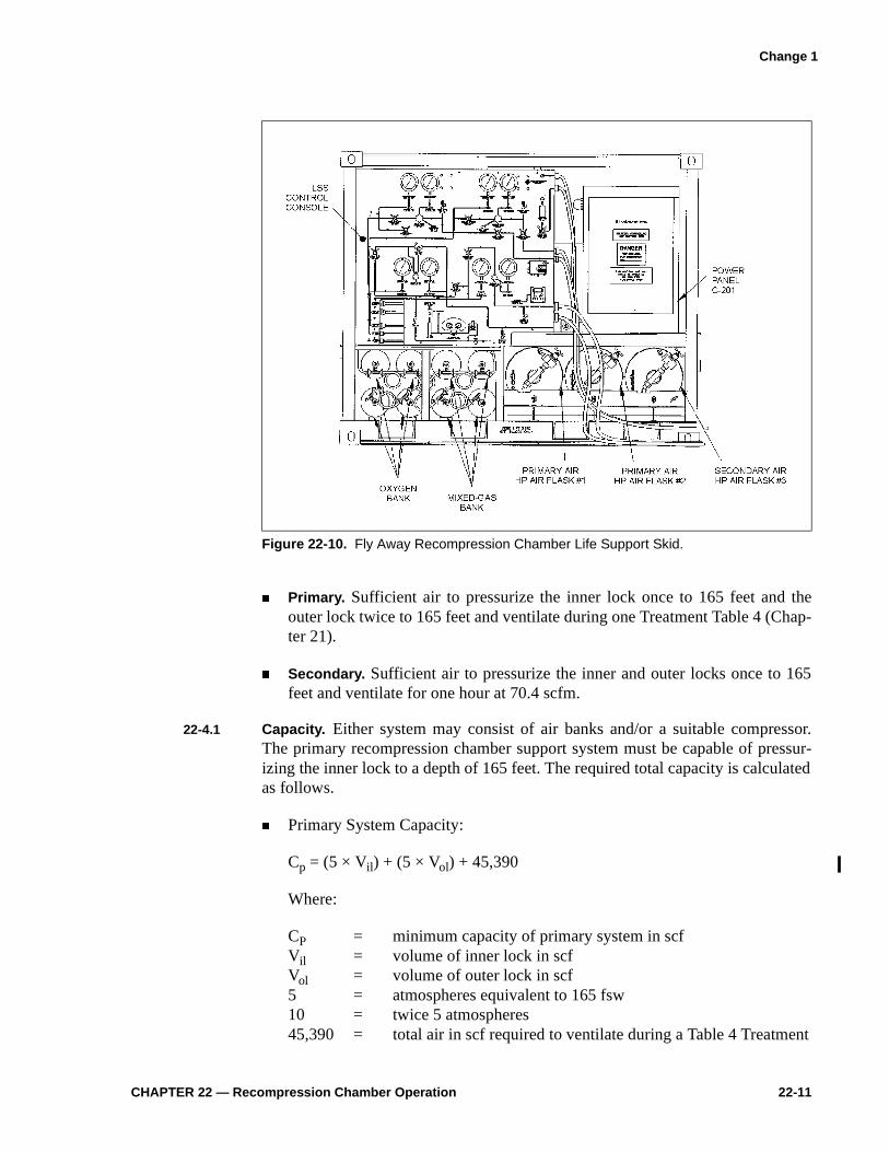
CHAPTER 22 — Recompression Chamber Operation 22-11
� Primary. Sufficient air to pressurize the inner lock once to 165 feet and theouter lock twice to 165 feet and ventilate during one Treatment Table 4 (Chap-ter 21).
� Secondary. Sufficient air to pressurize the inner and outer locks once to 165feet and ventilate for one hour at 70.4 scfm.
22-4.1 Capacity. Either system may consist of air banks and/or a suitable compressor.The primary recompression chamber support system must be capable of pressur-izing the inner lock to a depth of 165 feet. The required total capacity is calculatedas follows.
� Primary System Capacity:
Cp = (5 × Vil) + (5 × Vol) + 45,390
Where:
CP = minimum capacity of primary system in scfVil = volume of inner lock in scfVol = volume of outer lock in scf5 = atmospheres equivalent to 165 fsw10 = twice 5 atmospheres45,390 = total air in scf required to ventilate during a Table 4 Treatment
Figure 22-10. Fly Away Recompression Chamber Life Support Skid.
Change 1
22-12 U.S. Navy Diving Manual—Volume 5
� Secondary System Capacity:
Cs = (5 × Vil) + (5 × Vol) + 4,224
Where:
Cs = minimum capacity of secondary system in scfVil = volume of inner lockVol = volume of outer lock5 = atmospheres equivalent to 165 fsw4224 = air in scf required for maximum ventilation rate of 70.4 scfm for
one hour (60 min)
22-5 OPERATION
22-5.1 Predive Checklist. To ensure each item is operational and ready for use, performthe equipment checks listed in the Recompression Chamber Predive Checklist,Figure 22-11a.
22-5.2 Safety Precautions.
� Do not use oil on any oxygen fitting, air fitting, or piece of equipment.
� Do not allow oxygen supply tanks to be depleted below 100 psig.
� Ensure dogs are in good operating condition and seals are tight.
� Do not leave doors dogged (if applicable) after pressurization.
� Do not allow open flames, smoking materials, or any flammables to be carriedinto the chamber.
� Do not permit electrical appliances to be used in the chamber unless listed inthe Authorized for Navy Use (ANU).
� Do not perform unauthorized repairs or modifications on the chamber supportsystems.
� Do not permit products in the chamber that may contaminate or off-gas intothe chamber atmosphere.
Change 1
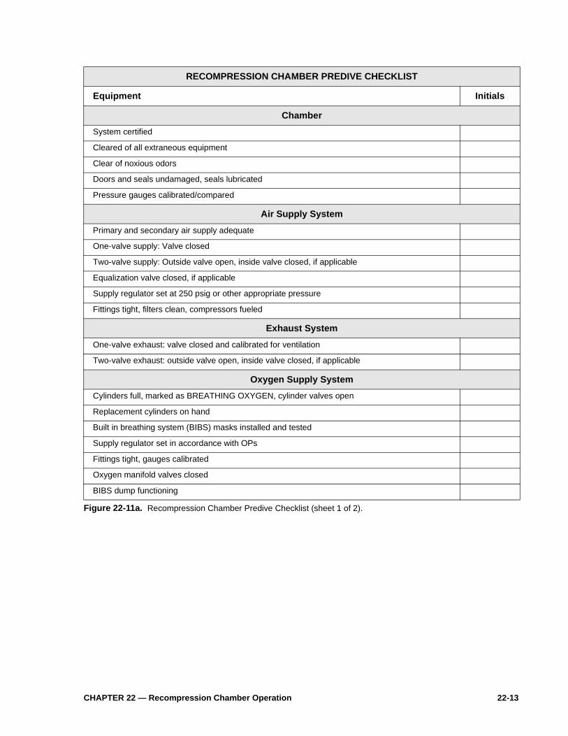
CHAPTER 22 — Recompression Chamber Operation 22-13
RECOMPRESSION CHAMBER PREDIVE CHECKLIST
Equipment Initials
Chamber
System certified
Cleared of all extraneous equipment
Clear of noxious odors
Doors and seals undamaged, seals lubricated
Pressure gauges calibrated/compared
Air Supply System
Primary and secondary air supply adequate
One-valve supply: Valve closed
Two-valve supply: Outside valve open, inside valve closed, if applicable
Equalization valve closed, if applicable
Supply regulator set at 250 psig or other appropriate pressure
Fittings tight, filters clean, compressors fueled
Exhaust System
One-valve exhaust: valve closed and calibrated for ventilation
Two-valve exhaust: outside valve open, inside valve closed, if applicable
Oxygen Supply System
Cylinders full, marked as BREATHING OXYGEN, cylinder valves open
Replacement cylinders on hand
Built in breathing system (BIBS) masks installed and tested
Supply regulator set in accordance with OPs
Fittings tight, gauges calibrated
Oxygen manifold valves closed
BIBS dump functioning
Figure 22-11a. Recompression Chamber Predive Checklist (sheet 1 of 2).

22-14 U.S. Navy Diving Manual—Volume 5
RECOMPRESSION CHAMBER PREDIVE CHECKLIST
Equipment Initials
Electrical System
Lights
Carbon dioxide analyzer calibrated
Oxygen analyzer calibrated
Temperature indicator calibrated
Carbon dioxide scrubber operational
Chamber conditioning unit operational
Direct Current (DC) power supply
Ground Fault Interrupter (GFI)
Communication System
Primary system tested
Secondary system tested
Fire Prevention System
Tank pressurized for chambers with installed fire suppression systems
Combustible material in metal enclosure
Fire-retardant clothing worn by all chamber occupants
Fire-resistant mattresses and blankets in chamber
Miscellaneous
Inside Chamber: CO2-absorbent canister with fresh absorbent installed
Urinal
Primary medical kit
Ear protection sound attenuators/aural protectors (1 set per person)Must have a 1/16” hole drilled to allow for equalization.
Outside Chamber: Heater/chiller unit
Stopwatches for recompression treatment time, decompressiontime, personnel leaving chamber time, and cumulative time
Fresh CO2 scrubber canister
U.S. Navy Diving Manual, Volume 5
Ventilation bill
Chamber log
Operating Procedures (OPs) and Emergency Procedures (EPs)
Secondary medical kit
Bedpan (to be locked in as required)
Figure 22-11b. Recompression Chamber Predive Checklist (sheet 2 of 2).
Change 1

CHAPTER 22 — Recompression Chamber Operation 22-25
22-6.2.5 Aluminum Chambers. Only steel chambers are painted. Aluminum chambers arenormally a dull, uneven gray color and corrosion can be easily recognized.Aluminum chambers will not be painted.
22-6.2.6 Fire Hazard Prevention. The greatest single hazard in the use of a recompressionchamber is from explosive fire. Fire may spread two to six times faster in a pres-surized chamber than at atmospheric conditions because of the high partialpressure of oxygen in the chamber atmosphere. The following precautions shall betaken to minimize fire hazard:
� Maintain the chamber oxygen percentage as close to 21 percent as possibleand never allow oxygen percentage to exceed 25 percent.
� Remove any fittings or equipment that do not conform with the standardrequirements for the electrical system or that are made of flammable materials.Permit no wooden deck gratings, benches, or shelving in the chamber.
� Use only mattresses designed for hyperbaric chambers. Use Durett Product orsubmarine mattress (NSN 7210-00-275-5878 or 5874). Other mattresses maycause atmospheric contamination. Mattresses should be enclosed in flame-proof covers. Use 100% cotton sheets and pillow cases. Put no more beddingin a chamber than is necessary for the comfort of the patient. Never use blan-kets of wool or synthetic fibers because of the possibility of sparks from staticelectricity.
� Keep oil and volatile materials out of the chamber. If any have been used,ensure that the chamber is thoroughly ventilated before pressurization. Do notput oil on or in any fittings or high-pressure line. If oil is spilled in the cham-ber or soaked into any chamber surface or equipment, it must be completelyremoved. If lubricants are required, use only those approved and listed inNaval Ships Technical Manual (NSTM) NAVSEA S9086-H7-STM-000,Chapter 262. Regularly inspect and clean air filters and accumulators in the airsupply lines to protect against the introduction of oil or other vapors into thechamber. Permit no one to wear oily clothing into the chamber.
� Permit no one to carry smoking materials, matches, lighters or any flammablematerials into a chamber. A WARNING sign should be posted outside thechamber. Example:
22-6.2.6.1 Fire Extinguishers. Only fire extinguishers listed on the NAVSEA Authorized forNavy Use (ANU) Lists are to be used.
WARNINGFire/Explosion Hazard. No matches, lighters, electrical appliances,
or flammable materials permitted in chamber.

22-26 U.S. Navy Diving Manual—Volume 5
22-7 DIVER CANDIDATE PRESSURE TEST
All U.S. Navy diver candidates shall be physically qualified in accordance withthe Manual of the Medical Department, Art. 15-66. Candidates shall also pass apressure test before they are eligible for diver training. This test may be conductedat any Navy certified recompression chamber, provided it is administered by qual-ified chamber personnel.
22-7.1 Candidate Requirements. The candidate must demonstrate the ability to equalizepressure in both ears to a depth of 60 fsw. The candidate shall have also passed thescreening physical readiness test in accordance with MILPERSMAN 1220-100,Exhibit 5.
22-7.2 Procedure.
1. Candidates shall undergo a diving physical examination by a Navy MedicalOfficer in accordance with the Manual of the Medical Department, Art. 15-66,and be qualified to undergo the test.
2. The candidates and the tender enter the recompression chamber and arepressurized to 60 fsw on air, at a rate of 75 fpm or less as tolerated by theoccupants.
3. If a candidate cannot complete the descent, the chamber is stopped and thecandidate is placed in the outer lock for return to the surface.
4. Stay at 60 fsw for at least 10 minutes.
5. Ascend to the surface following standard air decompression procedures.
6. All candidates shall remain at the immediate chamber site for a minimum of15 minutes and at the test facility for 1 hour. Candidates or tenders who mustreturn to their command via air travel must proceed in accordance withChapter 9, paragraph 9-13.
22-7.2.1 References.
� Navy Military Personnel Manual, Art. 1220-100� Manual of the Medical Department, Art. 15-66� SECNAVINST 12000.2A
Change 1