Embed Size (px)
Citation preview
MIL-STD-883K
METHOD 1014.15 25 April 2016
1
METHOD 1014.15
SEAL
1. PURPOSE. The purpose of this test is to determine the effectiveness (hermeticity) of the seal of microelectronic devices with designed internal cavities. 1.1 Definitions.
a. Standard leak rate. That quantity of dry air at 25C in atmosphere cubic centimeters flowing through a leak or multiple leak paths per second when the high-pressure side is at 1 atmosphere (760 mm Hg absolute) and the low-pressure side is at near total vacuum (see 1.1f below). Standard leak rate shall be expressed in units of atmosphere cubic centimeters per second of air (atm cm3/s air).
b. Measured leak rate. The implied leak rate that is measured on the detector for a given package using the specified
conditions and employing a specified test medium (tracer gas) specific to that detector. Measured leak rate is expressed in units of atmosphere cubic centimeters per second (atm cm3/s) for the medium used.
c. Leak-rate conversion factors for various test media.
atm cm3/s (Kr85) X 1.71 = atm cm3/s (air) atm cm3/s (Kr85) X 4.61 = atm cm3/s (He) atm cm3/s (He) X 0.37 = atm cm3/s (air) atm cm3/s (OLhe) X 0.37 = atm cm3/s (air) atm cm3/s (OLN2) X 0.98 = atm cm3/s (air) atm cm3/s (OLaIr) X 1.00 = atm cm3/s (air)
d. Equivalent standard leak rate. The leak rate that a given package would have under the standard conditions of 1.1a. The
equivalent standard leak rate is determined by converting the implied leakage measured (La, R, Q or OL) to those conditions of 1.1c using appropriate calculations. For the purpose of comparison with rates determined by various media, the equivalent standard leak rate (for the medium used in the test) must be converted to the equivalent standard leak rate for the comparative medium (generally converted to air equivalents). The equivalent standard air leak rate shall be expressed in units of atmosphere cubic centimeters per second of air (atm cm3/s air). (1) La is the equivalent standard leak rate a package has expressed in term for air, or after converting to air from
another medium. (2) L is the maximum allowed equivalent standard leak rate La permitted for a package based on Table VII limits. For
pass/fail criteria, L is compared to La. (3) R is the implied leak rate of the medium (such as helium) as measured (such as on a mass spectrometer). (4) R1 is the maximum allowed leak rate for the medium used. It is based on L using calculations to adjust for the
specific test conditions used in the measurement (see paragraph 2.1.2.3). For pass/fail criteria, R is compared to R1.
(5) Q is the implied leak rate of the medium (such as Krypton 85 (Kr85)) as measured on a radioisotope detector (see paragraph 2.2.6.c).
(6) Qs is the maximum allowed leak rate for the medium used. It is based on L using calculations to adjust for the specific test conditions used in the measurement (see paragraph 2.2.5.1). For pass/fail criteria, Q is compared to Qs.
(7) OL is the implied leak rate as measured on an optical leak detector. The test gas is denoted as OLair, OLN2, or OLHe.
e. Internal free-volume. The volume of the gas (or air) within a device package that could escape should the package leak. It
is the volume of the internal package minus the circuitry, elements, or other physical displacements within the package. f. Near total vacuum. The reduction of atmospheric pressure to 2 mm Hg or less, absolute.
g. Pounds per square inch absolute (psia) gas. The sum of gauge pressure in the tank and barometric pressure. A tank
showing zero gauge pressure is balancing the atmospheric conditions, hence has one atmosphere pressure (1 atm) inside. Absolute pressure takes this into consideration and is a measure of true content including this initial content. Thus, psia is the sum of the gauge pressure plus the barometric pressure.
*
*
*
MIL-STD-883K
METHOD 1014.15 25 April 2016
2
1.2 Test Conditions. The following procedures are covered by this method:
1.2.1 Trace Gas (He). 1/
A1 Fixed Fine Leak A2 Flexible Fine Leak A4 Fine Leak, applicable to the unsealed package. A5 Combined He/O2 dry gross leak, and, He fine leak (per A1 or A2) by mass spectrometry
1.2.2 Radioisotope (Kr85).
B1 Fine Leak B2 Gross Leak B3 Wet Gross Leak
1.2.3 Perfluorocarbon Gross Leak.
C1 Fixed Method that uses a liquid bath. C2 has been replaced by C1. C3 Fixed Method that uses a vapor detection system instead of an indicator bath.
1.2.4 Optical.
C4 Gross Leak C4 and C5 Combined Gross and Fine Leak
1.2.5 Penetrant Dye Gross Leak.
D Penetrant dye gross leak
1.2.6 Weight Gain Gross Leak. E Weight gain gross leak
.
1.2.7 Radioisotope (Kr85). G1 Thermal Leak Test for the evaluation of package hermetic integrity at elevated temperature.
1.2.8 Cumulative Helium Leak Detection (CHLD).
CH1 Fixed Leak Detection for both Fine and Gross leak using the CHLD System. CH2 Flexible Leak Detection for both Fine and Gross leak using the CHLD System. Z He Gross Leak Detection combined with one of several other tracer gases for Fine Leak Detection using the CHLD
System.
1/ A3 was intentionally omitted.
*
*
*
MIL-STD-883K
METHOD 1014.15 25 April 2016
3
1.3 Test Structure. Fine and gross leak tests shall be conducted in accordance with the requirements and procedures of the specified test condition. Testing order shall be fine leak (condition A or B1) followed by gross leak (condition B2, C1, C3, D, or E) except when B2 is used together with A, B1. . C4 and C5 may be performed together. Condition A5 is a combination dry gross and fine leak test and therefore gross leak may be used prior to fine leak tests. Condition B2 is a dry gas gross leak test and may be used prior to fine leak tests. When using the radioisotope tests, it is recommended practice to use B2 first to remove gross leakers prior to the fine leak test B1, which minimizes the Kr85 entrapped in rejected devices. When specified (see 4), measurements after test shall be conducted following the leak test procedures. Devices to be tested for thermal leakage shall first be subjected to a radioisotope gross leak test (B2), a radioisotope fine leak test (B1), or a gross/fine combination leak test, (B2/B1). Where bomb pressure specified exceeds the microcircuit package capability, alternate pressure, exposure time, and dwell time conditions may be used provided they satisfy the leak rate, pressure, time relationships which apply, and provided a minimum of 30 psia (2 atmospheres absolute) bomb pressure is applied in any case or for condition C4, a minimum of 10 psi differential test pressure is applied in any case. When test condition B2 is used to test large surface devices, a bomb pressure of 20 psia minimum may be used with the appropriate increase in bomb time (see paragraph 2.2.5.1). When test condition A4 is used, gross leak testing is not required. However A4 shall not be used in lieu of the required seal testing of lidded packages. When batch testing (more than one device in the leak detector at one time) is used in performing test condition A or B and a reject condition occurs it shall be noted as a batch failure. Each device may then be tested individually one time for acceptance if all devices in the batch are retested within one hour after removal from the tracer gas pressurization chamber. For condition B1, B2 only, devices may be batch tested and/or individually remeasured for acceptance providing all measuring is completed within one-half hour for B1 and within 10 minutes for B2 or combination B2/B1, after removal from the tracer gas pressurization chamber. For condition C3 only, devices that are batch tested, and indicate a reject condition, may be retested individually one time using the procedure of 2.3.4.1 herein, except that re-pressurization is not required if the devices are immersed in detector fluid within 20 seconds after completion of the first test, and they remain in the bath until retest. For conditions C4 and C5 only, the package must meet construction requirements defined in 2.4.1. This includes devices that are conformal coated such as circuit board assemblies.
1.3.1 Retest. Devices which fail gross leak may be retested destructively. If the retest shows a device to pass, that was originally thought to be a failure, then the device need not be counted as a failure in the accept number of sample size number calculations. Devices which fail fine leak shall not be retested for acceptance unless specifically permitted by the applicable acquisition document. The applicable acquisition document must also state that a failed device that passes retest needs not be counted as a failure in the sample size accept number calculations, otherwise if will count. Where fine leak retest is permitted, the entire leak test procedure for the specified test condition shall be repeated. That is, retest consisting of a second observation on leak detection without a re-exposure to the tracer fluid or gas under the specified test condition shall not be permissible under any circumstances. Preliminary measurement to detect residual tracer gas is advisable before any retest. 1.3.2 Failure criteria. The failure criteria for Fine Leak is provided in Table VII of paragraph 3. Failure criteria for other conditions; i.e., Gross Leak and Thermal Leak, is provided following the procedure for each individual test. 1.4 Apparatus. The apparatus required for the seal test shall be as indicated in the procedure for the applicable test condition being performed.
*
MIL-STD-883K
METHOD 1014.15 25 April 2016
4
2. TEST CONDITIONS. 2.1 Test Conditions A1, A2, A4 and A5 fine leak tracer gas (He). 1/
2.1.1 Apparatus. Apparatus required shall consist of suitable pressure and vacuum chambers and a mass spectrometer-type
leak detector preset and properly calibrated for a helium leak rate sensitivity sufficient to read measured helium leak rates of 10-9 atm cm3/s and greater. The volume of the chamber used for leak rate measurement should be held to the minimum practical, since this chamber volume has an adverse effect on sensitivity limits. The leak detector indicator shall be calibrated using a diffusion-type calibrated standard leak at least once during every working shift. In addition for test condition A4, the following apparatus is required: a. Fixture and fittings to mate the package to be tested to the leak detector. b. Surgical rubber gasket. c. Apiezon grease (type M or N), perfluorocarbon fluid 2/, or equivalent, if required to obtain seal. d. In addition for test condition A5, the following apparatus shall be required:
1. A mass spectrometer system capable of measuring the gas pressure in the sample test chamber and mass spectrometer chamber during the entire test process, and, qualitative measurement of helium and oxygen as a gross leak measurement during the evacuation process prior to quantitative measurement of the helium fine leak rate per condition A2.
2. A computer data system capable of permanently recording the entire test process. 3. Metal filler blocks to reduce empty space in the sample test chamber, as needed, to achieve the required helium
detection levels. 4. Two (2) calibrated NIST traceable helium leak rate standards, one having a calibrated leak rate equal to or below the
measured helium leak rate acceptance level (R1) and the other having a calibrated helium leak rate at least one (1) decade but not greater than three (3) decades above the measured helium leak rate acceptance level (R1).
5. A nitrogen or argon (99.9%) flow to flush room air from the sample test chamber before starting a test.
2.1.2 Procedures. Test condition A1 is a "fixed" method with specified conditions in accordance with Table I that will ensure the test sensitivity necessary to detect the reject limit (R1). Test condition A2 is a "flexible" method that allows the variance of test conditions in accordance with the formula of 2.1.2.3 to detect the specified equivalent standard leak rate (L) at a predetermined reject limit (R1). Test condition A4 is a method that measures the leak rate (R) of an unsealed package. 2.1.2.1 Test conditions A1 and A2, and A5 procedures applicable to "fixed" and "flexible" methods. Insert the completed device(s) into the sealed pressure chamber. The air inside the chamber shall then be evacuated to near total vacuum and then pressurized with 100 +0/-5 percent pure helium. Alternatively, a series of helium refills and vents may be performed until the minimum helium content is obtained. Once the required helium concentration is obtained, the pressure chamber can be set to the required pressure and time for the device(s). The pressure shall then be relieved and each specimen transferred, within the specified dwell time, to another chamber or chambers which are connected to the evacuating system and a mass-spectrometer-type leak detector. When the mass-spectrometer chamber(s) is evacuated, any tracer gas which was previously forced into the specimen will thus be drawn out and indicated by the leak detector as a measured leak rate (R). (The number of devices removed from pressurization for leak testing shall be limited such that the test of the last device can be completed within the dwell times listed in Table 1 for test condition A1 or within the chosen value of dwell time t2 for test condition A2.) NOTE: The Flexible Method A2 shall be used unless otherwise specified in the acquisition document, purchase order, or contract. 1/ A3 was intentionally omitted. 2/ Perfluorocarbons contain no chlorine or hydrogen.
*
*
*
MIL-STD-883K
METHOD 1014.15 25 April 2016
5
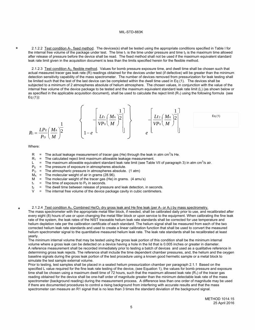
2.1.2.2 Test condition A1, fixed method. The devices(s) shall be tested using the appropriate conditions specified in Table I for the internal free volume of the package under test. The time t1 is the time under pressure and time t2 is the maximum time allowed after release of pressure before the device shall be read. The fixed method shall not be used if the maximum equivalent standard leak rate limit given in the acquisition document is less than the limits specified herein for the flexible method. 2.1.2.3 Test condition A2, flexible method. Values for bomb pressure exposure time, and dwell time shall be chosen such that actual measured tracer gas leak rate (R) readings obtained for the devices under test (if defective) will be greater than the minimum detection sensitivity capability of the mass spectrometer. The number of devices removed from pressurization for leak testing shall be limited such that the test of the last device can be completed within the dwell time used in Eq (1). The devices shall be subjected to a minimum of 2 atmospheres absolute of helium atmosphere. The chosen values, in conjunction with the value of the internal free volume of the device package to be tested and the maximum equivalent standard leak rate limit (L) (as shown below or as specified in the applicable acquisition document), shall be used to calculate the reject limit (R1) using the following formula (see Eq (1)):
2
1
2
1
12
1 0
2
0
1
1
M
M
VP
Lt
e
M
M
VP
Lt
eM
M
P
LPR
AA
A
O
E
Where: R = The actual leakage measurement of tracer gas (He) through the leak in atm cm3/s He. R1 = The calculated reject limit maximum allowable leakage measurement. L = The maximum allowable equivalent standard leak rate limit (see Table VII of paragraph 3) in atm cm3/s air. PE = The pressure of exposure in atmospheres absolute. PO = The atmospheric pressure in atmospheres absolute. (1 atm) MA = The molecular weight of air in grams (28.96). M = The molecular weight of the tracer gas (He) in grams. (4 amu’s) t1 = The time of exposure to PE in seconds. t2 = The dwell time between release of pressure and leak detection, in seconds. V = The internal free volume of the device package cavity in cubic centimeters.
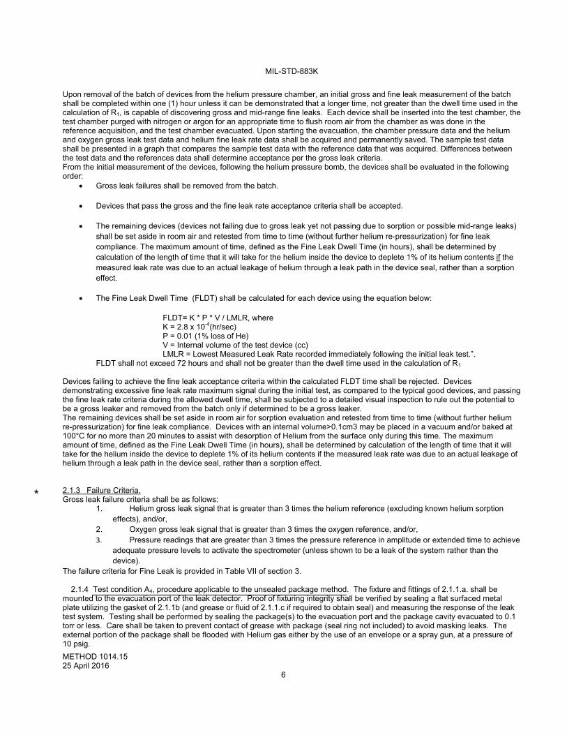
2.1.2.4 Test condition A5, Combined He/O2 dry gross leak and He fine leak (per A1 or A2) by mass spectrometry. The mass spectrometer with the appropriate metal filler block, if needed, shall be calibrated daily prior to use, and recalibrated after every eight (8) hours of use or upon changing the metal filler block or upon service to the equipment. When calibrating the fine leak rate of the system, the leak rates of the NIST traceable helium leak rate standards shall be corrected for use temperature and helium depletion rate per the calibration certificate of each standard. The helium signal shall be measured from each of the two corrected helium leak rate standards and used to create a linear calibration function that shall be used to convert the measured helium spectrometer signal to the quantitative measured helium leak rate. The leak rate standards shall be recalibrated at least yearly. The minimum internal volume that may be tested using the gross leak portion of this condition shall be the minimum internal volume where a gross leak can be detected on a device having a hole in the lid that is 0.005 inches or greater in diameter. A reference measurement shall be recorded immediately prior to testing a batch of devices and used as a qualitative reference in determining gross leak rejects. The reference shall include the time dependent chamber pressures, and, the helium and the oxygen baseline signals during the gross leak portion of the test procedure using a known good hermetic sample or a metal block to simulate the test sample external volume. Prior to testing, test samples shall be placed in a sealed helium pressurization chamber per paragraph 2.1.1 Based on the specified L value required for the fine leak rate testing of the device, (see Equation 1), the values for bomb pressure and exposure time shall be chosen using a maximum dwell time of 72 hours, such that the maximum allowed leak rate (R1) of the tracer gas reading obtained for the device shall be one-half order of magnitude greater than the minimum detectable leak rate of the mass spectrometer (background reading) during the measurement process. A difference less than one order of magnitude may be used if there are documented procedures to control a rising background from interfering with accurate results and that the mass spectrometer can measure an R1 signal that is no less than 3 times the standard deviation of the background signal.
Eq (1)
*
*
MIL-STD-883K
METHOD 1014.15 25 April 2016
6
Upon removal of the batch of devices from the helium pressure chamber, an initial gross and fine leak measurement of the batch shall be completed within one (1) hour unless it can be demonstrated that a longer time, not greater than the dwell time used in the calculation of R1, is capable of discovering gross and mid-range fine leaks. Each device shall be inserted into the test chamber, the test chamber purged with nitrogen or argon for an appropriate time to flush room air from the chamber as was done in the reference acquisition, and the test chamber evacuated. Upon starting the evacuation, the chamber pressure data and the helium and oxygen gross leak test data and helium fine leak rate data shall be acquired and permanently saved. The sample test data shall be presented in a graph that compares the sample test data with the reference data that was acquired. Differences between the test data and the references data shall determine acceptance per the gross leak criteria. From the initial measurement of the devices, following the helium pressure bomb, the devices shall be evaluated in the following order:
Gross leak failures shall be removed from the batch.
Devices that pass the gross and the fine leak rate acceptance criteria shall be accepted.
The remaining devices (devices not failing due to gross leak yet not passing due to sorption or possible mid-range leaks) shall be set aside in room air and retested from time to time (without further helium re-pressurization) for fine leak compliance. The maximum amount of time, defined as the Fine Leak Dwell Time (in hours), shall be determined by calculation of the length of time that it will take for the helium inside the device to deplete 1% of its helium contents if the measured leak rate was due to an actual leakage of helium through a leak path in the device seal, rather than a sorption effect.
The Fine Leak Dwell Time (FLDT) shall be calculated for each device using the equation below:
FLDT= K * P * V / LMLR, where K = 2.8 x 10⁻⁴(hr/sec)
P = 0.01 (1% loss of He) V = Internal volume of the test device (cc) LMLR = Lowest Measured Leak Rate recorded immediately following the initial leak test.”.
FLDT shall not exceed 72 hours and shall not be greater than the dwell time used in the calculation of R1 Devices failing to achieve the fine leak acceptance criteria within the calculated FLDT time shall be rejected. Devices demonstrating excessive fine leak rate maximum signal during the initial test, as compared to the typical good devices, and passing the fine leak rate criteria during the allowed dwell time, shall be subjected to a detailed visual inspection to rule out the potential to be a gross leaker and removed from the batch only if determined to be a gross leaker. The remaining devices shall be set aside in room air for sorption evaluation and retested from time to time (without further helium re-pressurization) for fine leak compliance. Devices with an internal volume>0.1cm3 may be placed in a vacuum and/or baked at 100°C for no more than 20 minutes to assist with desorption of Helium from the surface only during this time. The maximum amount of time, defined as the Fine Leak Dwell Time (in hours), shall be determined by calculation of the length of time that it will take for the helium inside the device to deplete 1% of its helium contents if the measured leak rate was due to an actual leakage of helium through a leak path in the device seal, rather than a sorption effect. 2.1.3 Failure Criteria. Gross leak failure criteria shall be as follows:
1. Helium gross leak signal that is greater than 3 times the helium reference (excluding known helium sorption effects), and/or,
2. Oxygen gross leak signal that is greater than 3 times the oxygen reference, and/or, 3. Pressure readings that are greater than 3 times the pressure reference in amplitude or extended time to achieve
adequate pressure levels to activate the spectrometer (unless shown to be a leak of the system rather than the device).
The failure criteria for Fine Leak is provided in Table VII of section 3. 2.1.4 Test condition A4, procedure applicable to the unsealed package method. The fixture and fittings of 2.1.1.a. shall be mounted to the evacuation port of the leak detector. Proof of fixturing integrity shall be verified by sealing a flat surfaced metal plate utilizing the gasket of 2.1.1b (and grease or fluid of 2.1.1.c if required to obtain seal) and measuring the response of the leak test system. Testing shall be performed by sealing the package(s) to the evacuation port and the package cavity evacuated to 0.1 torr or less. Care shall be taken to prevent contact of grease with package (seal ring not included) to avoid masking leaks. The external portion of the package shall be flooded with Helium gas either by the use of an envelope or a spray gun, at a pressure of 10 psig.
*
MIL-STD-883K
METHOD 1014.15 25 April 2016
7
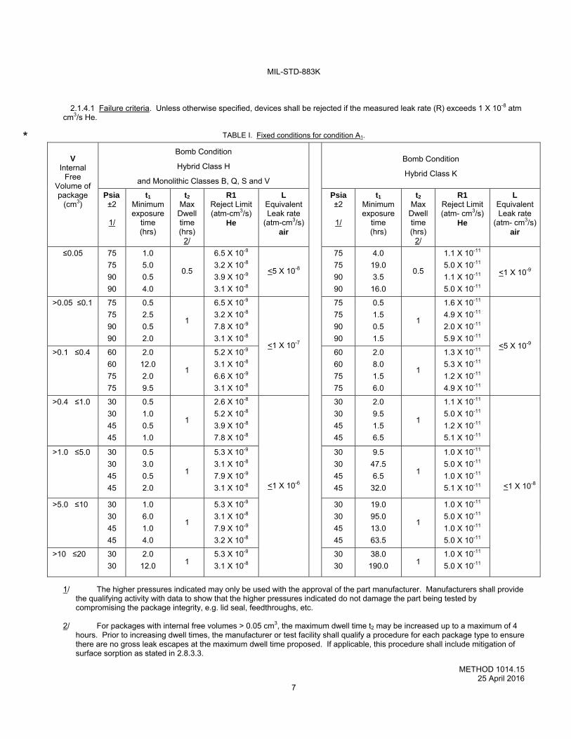
2.1.4.1 Failure criteria. Unless otherwise specified, devices shall be rejected if the measured leak rate (R) exceeds 1 X 10⁻⁸ atm cm3/s He.
TABLE I. Fixed conditions for condition A1.
V
Internal Free
Volume of package
(cm3)
Bomb Condition
Hybrid Class H
and Monolithic Classes B, Q, S and V
Bomb Condition
Hybrid Class K
Psia ±2
1/
t1 Minimum exposure
time (hrs)
t2 Max
Dwell time (hrs)
2/
R1 Reject Limit (atm-cm3/s)
He
L Equivalent Leak rate
(atm-cm3/s) air
Psia ±2
1/
t1 Minimum exposure
time (hrs)
t2 Max
Dwell time (hrs)
2/
R1 Reject Limit (atm- cm3/s)
He
L Equivalent Leak rate
(atm- cm3/s)air
≤0.05 75
75
90
90
1.0
5.0
0.5
4.0
0.5
6.5 X 10⁻⁹
3.2 X 10⁻⁸
3.9 X 10⁻⁹
3.1 X 10⁻⁸
<5 X 10⁻⁸
75
75
90
90
4.0
19.0
3.5
16.0
0.5
1.1 X 10⁻¹¹
5.0 X 10⁻¹¹
1.1 X 10⁻¹¹
5.0 X 10⁻¹¹
<1 X 10⁻⁹
>0.05 ≤0.1 75
75
90
90
0.5
2.5
0.5
2.0
1
6.5 X 10⁻⁹
3.2 X 10⁻⁸
7.8 X 10⁻⁹
3.1 X 10⁻⁸ <1 X 10⁻⁷
75
75
90
90
0.5
1.5
0.5
1.5
1
1.6 X 10⁻¹¹
4.9 X 10⁻¹¹
2.0 X 10⁻¹¹
5.9 X 10⁻¹¹ <5 X 10⁻⁹
>0.1 ≤0.4 60
60
75
75
2.0
12.0
2.0
9.5
1
5.2 X 10⁻⁹
3.1 X 10⁻⁸
6.6 X 10⁻⁹
3.1 X 10⁻⁸
60
60
75
75
2.0
8.0
1.5
6.0
1
1.3 X 10⁻¹¹
5.3 X 10⁻¹¹
1.2 X 10⁻¹¹
4.9 X 10⁻¹¹
>0.4 ≤1.0 30
30
45
45
0.5
1.0
0.5
1.0
1
2.6 X 10⁻⁸
5.2 X 10⁻⁸
3.9 X 10⁻⁸
7.8 X 10⁻⁸
<1 X 10⁻⁶
30
30
45
45
2.0
9.5
1.5
6.5
1
1.1 X 10⁻¹¹
5.0 X 10⁻¹¹
1.2 X 10⁻¹¹
5.1 X 10⁻¹¹
<1 X 10⁻⁸
>1.0 ≤5.0 30
30
45
45
0.5
3.0
0.5
2.0
1
5.3 X 10⁻⁹
3.1 X 10⁻⁸
7.9 X 10⁻⁹
3.1 X 10⁻⁸
30
30
45
45
9.5
47.5
6.5
32.0
1
1.0 X 10⁻¹¹
5.0 X 10⁻¹¹
1.0 X 10⁻¹¹
5.1 X 10⁻¹¹
>5.0 ≤10 30
30
45
45
1.0
6.0
1.0
4.0
1
5.3 X 10⁻⁹
3.1 X 10⁻⁸
7.9 X 10⁻⁹
3.2 X 10⁻⁸
30
30
45
45
19.0
95.0
13.0
63.5
1
1.0 X 10⁻¹¹
5.0 X 10⁻¹¹
1.0 X 10⁻¹¹
5.0 X 10⁻¹¹
>10 ≤20 30
30
2.0
12.0 1 5.3 X 10⁻⁹
3.1 X 10⁻⁸
30
30
38.0
190.0 1 1.0 X 10⁻¹¹
5.0 X 10⁻¹¹
1/ The higher pressures indicated may only be used with the approval of the part manufacturer. Manufacturers shall provide the qualifying activity with data to show that the higher pressures indicated do not damage the part being tested by compromising the package integrity, e.g. lid seal, feedthroughs, etc.
2/ For packages with internal free volumes > 0.05 cm3, the maximum dwell time t2 may be increased up to a maximum of 4
hours. Prior to increasing dwell times, the manufacturer or test facility shall qualify a procedure for each package type to ensure there are no gross leak escapes at the maximum dwell time proposed. If applicable, this procedure shall include mitigation of surface sorption as stated in 2.8.3.3.
*
MIL-STD-883K
METHOD 1014.15 25 April 2016
8
2.2 Test Condition B, Radioisotope.
2.2.1 Radioisotope leak test apparatus. Apparatus for this test shall consist of:
a. Radioactive tracer gas pressurization console containing a Kr85/air mixture.
b. Counting equipment consisting of a scintillation crystal, photomultiplier tube, preamplifier, ratemeter, and Kr85 reference standards. The counting station shall be of sufficient sensitivity to determine through the device wall the radiation level of any Kr85 tracer gas present within the device.
(1) A “Flat Top Scintillation Crystal” counting station shall have a minimum sensitivity of 4,500 c/m/µCi Kr85 and a
minimum detectable count rate of 500 counts per minute above ambient background. (2) A “Well Crystal” counting station shall have a minimum sensitivity of 10,000 c/m/µCi Kr85 and a minimum
detectable count rate of 500 counts per minute above ambient background. (3) A “Tunnel Crystal” counting station shall have a minimum sensitivity of 4,500 c/m/µCi Kr85 and a minimum
detectable count rate of 500 counts per minute above ambient background.
The counting station operator shall perform a functional check at least once every shift using Kr85 reference standards and following the equipment manufacturer's instruction. The actual calibration reading shall be recorded for each scintillation crystal detection system (Well, Tunnel, and Flat top) prior to performing testing.
c. A tracer gas that consists of a mixture of Kr85 and air. The concentration of the Kr85 in the Kr85/air mixture shall be no
less than 100 micro-curies per atmospheric cubic centimeter. The determined values of each analytical sample shall be recorded in accordance with the calibration requirements of this standard (see 4.5.1 of MIL-STD-883). The specific activity may be measured automatically by the equipment during cycling of the equipment. If not, then an analytical sample of the Kr85 shall be taken at least once each 30 days to determine when the concentration drops by 5 percent in concentration and specific activity. If production use of the pressurization console averages 1000 or fewer bombings during the month, analytical sampling may be annually. When the concentration drops by 5 percent, corrective action shall be taken to adjust the concentration.
d. ESD Protective Tubes shall be utilized to ensure the system is ESD safe when using the Well Counting Station. e. All calibration records (e.g. daily, monthly, voltage crystal plateau graphs, and C of C for Kr85 reference standard, specific
activity etc.) shall be maintained and made available to the qualifying activity. f. The crystal voltage plateau graph shall be performed and documented semiannually. Examples of good plateau graphs
and bad plateau graphs shall be included in the internal procedure.
2.2.2 Test condition B2 – radioisotope gross leak package qualification. This test shall be used to qualify all packages with less than 0.1 cm3 internal free volume that will undergo screening tests per the B2 radioisotope gross leak, or the B2/B1 gross/fine leak combination test (see paragraph 2.2.6.b and c). The purpose is to assure that if such a packages has a leak, then that leak will be detectable under test conditions B2 and B2/B1. Packages having 0.1 cm3 internal free volume or larger do not require package qualification. Packages smaller than 0.1 cm3 internal free volume shall be subjected to the following requirements:
a. A 5 mil diameter hole shall be made in a representative sample of the devices to be tested.
b. The device shall be subjected to this test condition and removed from the pressurization tank. The device shall be measured in the counting station immediately after the tank is vented to atmosphere. A “net” reading indication of 500 counts per minute or greater is considered a reject. The device must remain a reject with a minimum of 500 counts per minute above ambient background for ten minutes after removal from the pressurization tank. If the device does not fail, test conditions B2 and B2/B1 shall not be used.
*
MIL-STD-883K
METHOD 1014.15 25 April 2016
9
2.2.3 Test condition B2 and B1 - radioisotope gross/fine combination leak. The apparatus for this test is that of paragraph 2.2. This test may be applied as a combination of conditions B2/B1 and is used in accordance with the requirements of those conditions for specified packages, as qualified under paragraph 2.2.2, with an atmosphere of Kr85/air mixture. Actual pressure and soak time for B1 shall be determined in accordance with paragraph 2.2.5.1. When the soak time is completed, the Kr85/air mixture shall be evacuated until 2.0 torr pressure exists in the pressurization chamber. The evacuation shall be completed within 3 minutes from either the end of the pressurization cycle or the point at which the chamber pressure reaches 60 psia (if a higher pressure than 60 psia was used). The chamber shall then immediately be backfilled with air and the test devices removed from the chamber. The devices shall be measured using a scintillation crystal equipped counting station as specified in paragraphs 2.2.4.1, 2.2.4.2, or 2.2.5.2. Devices subjected to this gross/fine combination test must be measured within 10 minutes after removal from the pressurization system. The R value shall not be less than 500 counts per minute above background. If all of the tested devices cannot be measured within 10 minutes after removal from the pressurization cycle, the remaining devices at 10 minutes must be re-tested as above in this paragraph.
2.2.4 Determination of counting efficiency (k). The counting efficiency (k), or k-factor, is the efficiency of measurement of
radioactive Kr85 tracer gas within a device using a scintillation crystal as a detector. The k-factor must be determined for the combination of both the scintillation crystal detection system that is to be used for the measurement and for the specific geometry of the device to be tested (see 2.2.4.1, 2.2.4.2, 2.2.4.3, or 2.2.5.2). This is done using a device ‘sample’ of the same geometric configuration as the device to be tested. The geometric center of the cavity, or its internal void, is the point called the “center of mass” of the radioactive gas being measured. The location of the center of mass is the point referred to for the k-factor of the device as it is positioned in each of the scintillation crystal detection systems described in 2.2.4.1, 2.2.4.2, 2.2.4.3, or 2.2.5.2. Once established, the k-factor for each package configuration shall be recorded. This record shall list the methodology and procedure used to obtain the k-factor and shall be made available to the qualifying activity upon request.
2.2.4.1 Scintillation “Well-Crystal”.
a. A representative sample, consisting of a device with the same geometric configuration as the test sample device(s), shall be used to determine the counting efficiency (k). This representative sample shall have an accurately known micro-curie content of Kr85 placed within its internal void.
b. The counts per minute from the representative sample shall be measured in the well of the shielded scintillation crystal of
the counting station. The sample device should be in the exact position as test devices will be tested. If not, then the sample device shall be located at a height not to be exceeded by any device tested (see note below). From this measured value the counting efficiency, in counts per micro-curie, shall be calculated for that device/crystal system.
Note: The counting efficiency of the scintillation well crystal is reduced systematically at higher locations within the
crystal’s well. The k-factor for the sample at the bottom of the well will be the greatest. If a device is placed on top of other devices such as in testing multiple devices simultaneously, then the top device will have the least measured k-factor effect. Thus, the measured k-factor, determination using the sample device located other than at the bottom of the crystal’s well, determines the maximum height to be allowed for the actual test. This height shall be established and shall not be exceeded by any actual test device, including any one of the multiple devices being simultaneously tested.
2.2.4.2 Scintillation “Flat-Top Crystal”.
a. A representative sample consisting of a device with the same geometric configuration as the test sample device(s) shall be
used to determine the counting efficiency (k). This representative sample shall have an accurately known micro-curie content of Kr85 placed within its internal void.
b. The counts per minute from the representative sample shall be measured on the shielded scintillation crystal of the
counting station. The sample must be in the exact position as the actual test devices will be tested. The k-factor for the sample shall be measured with the sample placed flat in a position centered to the main body of the crystal. Some flat-top crystals are solid cylinders of approximately 3 inches diameter, and the device sample is placed on the cylinder in the same manner, as mentioned. From this measured value, the counting efficiency, in counts per minute per micro-curie shall be calculated for that device/crystal system.
MIL-STD-883K
METHOD 1014.15 25 April 2016
10
2.2.4.3 Scintillation “Tunnel Crystal”.
a. A Tunnel Crystal is either a solid block scintillation crystal similar to a flat-top crystal with an open tunnel through the body
or can be a pair of solid scintillation crystals place one above the other in a parallel configuration. Devices pass through the tunnel or between the parallel crystals, usually on a conveyer belt, allowing dynamic measurements. This configuration is commonly used in high volume testing.
b. The k-factor must be determined for the Tunnel Crystal’s dynamic condition which is usually less than in a static condition with
the device standing at the center of the tunnel. See paragraph 2.2.5.2 to establish the k-factor for the sample using such a configuration. Alternately, this k-factor determination is commonly determined by the manufacturer upon request.
2.2.5 Test condition B1, radioisotope fine or B2/B1 gross/fine leak combination test.
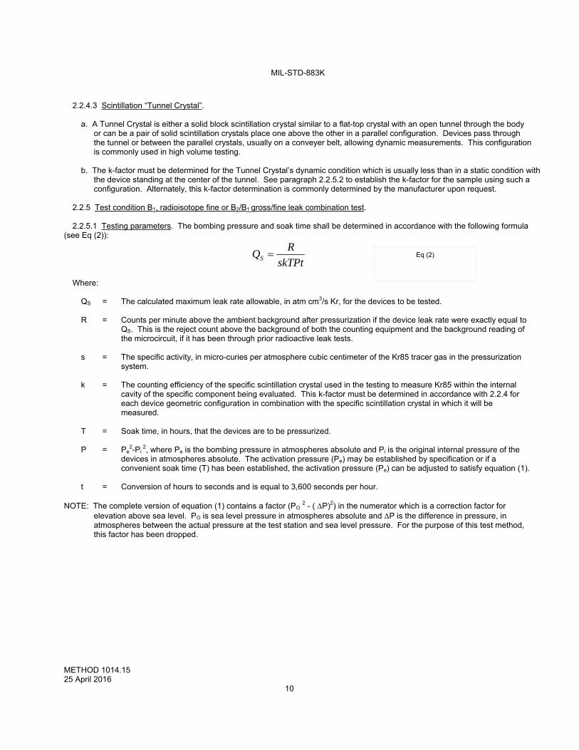
2.2.5.1 Testing parameters. The bombing pressure and soak time shall be determined in accordance with the following formula (see Eq (2)):
skTPt
RQS
Where: QS = The calculated maximum leak rate allowable, in atm cm3/s Kr, for the devices to be tested. R = Counts per minute above the ambient background after pressurization if the device leak rate were exactly equal to
QS. This is the reject count above the background of both the counting equipment and the background reading of the microcircuit, if it has been through prior radioactive leak tests.
s = The specific activity, in micro-curies per atmosphere cubic centimeter of the Kr85 tracer gas in the pressurization
system. k = The counting efficiency of the specific scintillation crystal used in the testing to measure Kr85 within the internal
cavity of the specific component being evaluated. This k-factor must be determined in accordance with 2.2.4 for each device geometric configuration in combination with the specific scintillation crystal in which it will be measured.
T = Soak time, in hours, that the devices are to be pressurized. P = Pe
2-Pi 2, where Pe is the bombing pressure in atmospheres absolute and Pi is the original internal pressure of the
devices in atmospheres absolute. The activation pressure (Pe) may be established by specification or if a convenient soak time (T) has been established, the activation pressure (Pe) can be adjusted to satisfy equation (1).
t = Conversion of hours to seconds and is equal to 3,600 seconds per hour. NOTE: The complete version of equation (1) contains a factor (PO 2 - ( P)2) in the numerator which is a correction factor for
elevation above sea level. PO is sea level pressure in atmospheres absolute and P is the difference in pressure, in atmospheres between the actual pressure at the test station and sea level pressure. For the purpose of this test method, this factor has been dropped.
Eq (2)
MIL-STD-883K
METHOD 1014.15 25 April 2016
11
2.2.5.2 Dynamic Measurement of the k-factor with a Scintillation-Crystal.
a. A representative sample consisting of a device with the same geometric configuration as the test sample device(s) shall be
used to determine the counting efficiency (k). This representative sample shall have an accurately known micro-curie content of Kr85 placed within its internal void.
b. A crystal, (or crystals), can be used for dynamic testing of devices passing over or through the crystal(s). This configuration
is commonly used in high volume testing. The k-factor must be determined in the ‘dynamic condition’, which will establish a k-factor value, (usually less than in a static condition with the device standing at the center of the tunnel.) The representative sample is measured dynamically, as it passes through the crystal. This establishes the maximum reading achievable for the sample. From this measured value, the counting efficiency, in counts per minute per micro-curie shall be calculated. This k-factor determination is most commonly determined by the equipment manufacturer.
2.2.5.3 Geometric configurations. The k-factor for each geometric configuration is determined and used for testing. As a
convenience, the same k-factor may apply to similar geometric configurations. This allows the same k-factor to be used for multiple devices, as long as the same test procedure and equipment is used, and the devices are measured using the same measurement system, (2.2.4.1, 2.2.4.2, or 2.2.5.2).
Scintillation “well” crystals are capable of detecting (measuring) a maximum reading of 16,000 to 18,000 counts per minute from the emission of one micro-curie of Kr85 contained within the cavity of a device. This maximum reading of Kr85 emission is achieved with the DUT placed deep into the well-crystal and with no shielding from other devices or fixtures.
The counting efficiency (k-factor) for most device configurations and crystal combinations may be available from the equipment manufacturer by providing the equipment manufacturer with representative samples of the same geometric configuration as the device to be tested. Suitable facilities shall retain record of how the k-factor was established for each package configuration and made available to the qualifying activity.
2.2.5.4 Evaluation of surface sorption and wait time. All device encapsulations consisting of glass, metal, and ceramic or combinations thereof, that also include external coatings and external sealants or labels, shall be evaluated for surface sorption of Kr85 before establishing the leak test parameters. Devices susceptible to surface sorption must “wait” for the surface sorption to dissipate before being tested. This time lapse shall be noted and shall determine the "wait time" specified in 2.2.6.
Representative samples with the questionable surface material shall be subjected to the predetermined pressure and time conditions established for the device configuration as specified by 2.2.5.1. The samples shall then be measured at the counting station every 10 minutes, with count rates noted. The total time taken for the count rate to become asymptotic is the “wait time”.
Devices which are determined to have surface absorption should first be subjected to the radioisotope gross leak test procedure (B2), and then to the fine leak test (B1). The gross leak procedure will remove all leaking devices with leak rates greater than 5 X 10⁻⁶ atm-cm3/sec.
2.2.5.4.1 Alternate β method. The surface sorption can also be determined by measuring the Beta (β) emission from any Kr85 absorbed into surface materials. The β particles will not penetrate the walls of the device; therefore, β emission detection means Kr85 is on the outer surfaces of a device. The β readings are monitored until they dissipate confirming the surface is free of Kr85 gas. This time to dissipate is the “wait time”.
2.2.5.4.2 Removal of surface sorption. Devices with cavities > 0.1 cm3, with leak rates in the fine leak range, will not lose their internal Kr85 gas in < 1 Hour. Therefore, such devices may be placed in a vacuum-oven at temperatures up to 100ºC and near total vacuum for 15-20 minutes following pressurization for B1 without the concern of losing internal Kr85. This vacuum-oven procedure is capable of removing surface absorbed Kr85 from paints and labels. The removal of that surface Kr85 from the surface materials is accurately confirmed by verifying that there is no Beta radiation from the surface.
MIL-STD-883K
METHOD 1014.15 25 April 2016
12
2.2.6 Test Procedure B1, Fine Leak; B2, Gross Leak; or B2/B1 Gross/Fine combination test. The devices shall be placed in a
radioactive tracer gas pressurization chamber. The pressurization chamber may be partially filled with inert material (aluminum filler blocks), to reduce the cycle time and increase the efficiency of the system. It is the equipment manufacturer’s recommendation that all ‘small-cavity’ devices be measured within 10 minutes after removal from the pressurization tank.
a. B1 - Fine Leak: The tank shall be evacuated to 0.5 torr. The devices shall be subjected to a minimum of 2 atmospheres absolute pressure of Kr85/air mixture. Actual pressure and soak time for B1 shall be determined in accordance with 2.2.5.1. When the ‘soak time’ is completed, the Kr85/air mixture shall be transferred to storage until 0.5 torr pressure exists in the pressurization chamber. The storage cycle shall be completed in 3 minutes maximum as measured from the end of the pressurization cycle or from the time the tank pressure reaches 60 psia if a higher bombing pressure was used. The tank shall then immediately be backfilled with air and the devices removed from the tank and measured within 1 hour after removal using a scintillation crystal equipped counting station as in 2.2.4.1, 2.2.4.2, or 2.2.5.2. Device encapsulations that come under the requirements of 2.2.5.4 shall be exposed to ambient air for a time not less than the ‘wait time’ determined by 2.2.5.4 (or following the bake cycle described in 2.2.5.4.2). Device encapsulations that do not come under the requirements of 2.2.5.4 may be tested without a ‘wait time’. The R value of 2.2.5.1 shall not be less than 500 counts per minute above background.
Note: If the devices are tested in the well crystal with the crystal wall shielded with a lead plug while measuring the device, and a background of approximately 500 counts per minute is achievable when the Ratemeter is in the “slow-time-constant” position, then reject values “R” of a minimum of 250 counts (net) above background may be measured for rejection of devices in high sensitivity testing.
b. B2 - Gross Leak: Only product qualified under paragraph 2.2.2 shall be authorized to use this method. The devices shall
be placed in a pressure chamber. The chamber shall be filled with inert material (aluminum filler blocks) so that the free volume is not greater than as qualified in 2.2.2. The tank shall be evacuated to 0.5 torr. The devices shall be subjected to a minimum of 2 atmospheres absolute pressure of Kr85/air mixture and the bomb time no less than 2 minutes. When the soak time is completed the Kr85/air mixture shall be transferred to storage until 2.0 torr pressure exists in the pressurization tank. The storage cycle shall be completed in 3 minutes maximum as measured from the end of the pressurization cycle. The tank shall then immediately be backfilled with air. The devices shall be removed from the tank and measured within 10 minutes after removal using a scintillation crystal equipped counting station as in 2.2.4.1, 2.2.4.2, 2.2.4.3 or 2.2.5.2. Any device indicating 500 counts per minute, or greater, above the ambient background of the counting station shall be considered a gross leak failure. If the devices are not all measured at the end of 10 minutes from removal from the pressurization chamber, the remaining devices shall be returned to the pressurization chamber and re-pressurized to a minimum of 30 psia for a minimum of 0.01 hrs, and then measured at the counting station within 10 minutes. The counting station shall be checked at least once every shift using a Kr85 reference standard following manufacturer’s procedure, and a record of proper function shall be maintained.
MIL-STD-883K
METHOD 1014.15 25 April 2016
13
c. B2/B1 - Gross/fine combination: Only product qualified under paragraph 2.2.2 shall be authorized to use this method. The
devices shall be placed in a pressure chamber. The chamber shall be filled with inert material (aluminum filler blocks) so that the free volume is not greater than as qualified in 2.2.2. The tank shall be evacuated to 0.5 torr. Actual pressure and soak time shall be in accordance with B1 paragraph 2.2.5.1. The R value in counts per minute shall not be less than 500 above background. When the soak time is completed the Kr85/air mixture shall be transferred to storage until 2.0 torr pressure is in the pressurization chamber. The storage cycle shall be completed in 3 minutes maximum as measured from the end of the pressurization cycle, or from the time the tank pressure reaches 60 psia if a higher bombing pressure was used. The tank shall then immediately be backfilled with air. The devices shall be removed from the tank and measured within 10 minutes after removal using a scintillation crystal equipped counting station as in 2.2.4.1, 2.2.4.2, 2.2.4.3 or 2.2.5.2. Devices that require a “wait-time” per paragraph 2.2.5.4, which exceeds 10 minutes, cannot be subjected to this combination test. If all devices cannot be measured within the 10 minute window, then the remaining devices shall be returned to the pressurization chamber and re-pressurized to a minimum of 30 psia for a minimum of 0.01 hours, and then measured at the counting station within 10 minutes. The counting station shall be checked at least once every shift using a Kr85 reference standard following manufacture’s procedure, and a record of proper function shall be maintained.
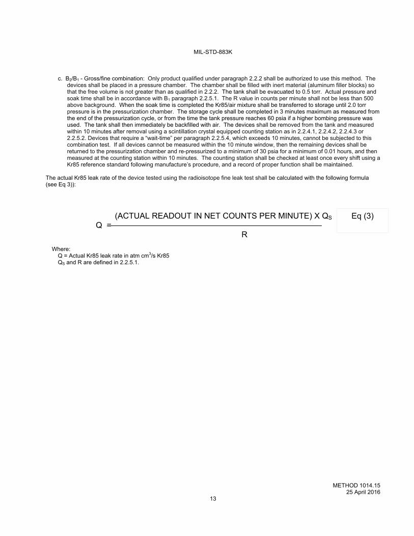
The actual Kr85 leak rate of the device tested using the radioisotope fine leak test shall be calculated with the following formula (see Eq 3)): (ACTUAL READOUT IN NET COUNTS PER MINUTE) X QS Q = R
Where: Q = Actual Kr85 leak rate in atm cm3/s Kr85 QS and R are defined in 2.2.5.1.
Eq (3)
MIL-STD-883K
METHOD 1014.15 25 April 2016
14
2.2.7 Test condition B3, Radioisotope Wet Gross Leak Test.
2.2.7.1 Intended Use. This is designed for small packages with less than 0.1 cm3 internal free volume and packages that have
not qualified to 2.2.2. This test may be used for larger than 0.1 cm3 internal free volume packages. Packages up to 0.1 cm3 internal free volume suspected of very large leaks are commonly subjected to this test.
2.2.7.2 Apparatus. Apparatus for this test shall be as in 2.2.1 and as follows:
a. A container of sufficient volume to allow the devices to be covered with red dye penetrant solution, evacuated, and subjected to air pressure in the same container.
b. Solutions:
(1) The red dye penetrant solution shall be kept clean and free of contaminants (including wash solvents). The
solutions shall be tested to verify the efficiency of the solution for both Kr85 gettering and visual detectability. The most efficient red dye solution uses a mixture, by volume, of 95% light viscosity mineral oil and 5% oil-based red dye indicator. The solution must be evaluated for Kr85 absorption and retention.
(2) The solvent for washing the devices after immersion shall be acetone.
2.2.7.3 Procedure. The following four steps shall be followed:
Step 1. The devices shall be immersed in the red dye penetrant solution and evacuated to a pressure of 100 torr (~ 24 inches Hg) or less for 10 minutes and then pressurized with air for 10 minutes minimum at 310 kPa (45 psia) minimum. The devices shall be removed from the red dye penetrant solution and placed in a fine-screen basket and flushed with acetone by applying a fine-spray of acetone to remove the surface film of the solution. It is recommended that the devices in the fine-screen basket be held over funnel, with the funnel inserted into a large Erlenmeyer flask, (thus minimizing the acetone vapors released into the room). Do not allow any acetone to contaminate the red dye penetrant solution. Immediately following the wash, the devices shall be emptied onto a white surface and examined visually for red dye penetrant solution exiting from any leaking devices. Look for evidence of red dye leakage that is apparent without using the aid of visual magnification. Any devices with red dye penetrant solution leaking from them shall be rejected as gross leakers and removed. Step 2. The remaining devices shall then be placed in the radioisotope pressurization chamber. The chamber shall be filled with inert material (aluminum filler blocks) so that the free volume is not greater than as qualified in 2.2.2. The chamber is evacuated to a pressure of 0.5 torr. The devices shall then be pressurized to a minimum of 45 psia of Kr85/air mixture for 0.2 hours minimum. The gas shall then be transferred to storage until a pressure of 2.0 torr maximum exists in the tank. This transfer shall be completed in 2 minutes maximum. The chamber shall then be filled with air, and the devices immediately removed from the tank and leak tested within 5 minutes after gas exposure, with a scintillation crystal equipped counting station. It is recommended that batch sizes be kept small enough to allow all devices to be measured within 5 minutes. Any device indicating 500 c/m or greater above the ambient background of the counting station shall be considered a gross leak. If all of the devices cannot be measured within 5 minutes, they shall be retested starting at the beginning of step 2. Step 3. Failing devices may cross contaminate compliant devices with red dye penetrant solution. Devices which contain red dye penetrant solution may effervesce after being pressurized with Kr85 and may lose the Kr85 trapped within them. The devices shall be emptied onto a white surface and examined carefully for any red dye penetrant solution exiting from any leaking devices. Any devices with red dye penetrant solution leaking from them shall be rejected as gross leakers. Gross leak failures with less than 0.1 cm3 internal free volume shall be visually inspected at 30X to confirm that the red dye penetrant solution is actually leaking from the device. Step 4. If any devices are rejected by Steps 1 – 3, the procedure (starting with Step 2) shall be performed again until no more gross leakers are found.
MIL-STD-883K
METHOD 1014.15 25 April 2016
15
2.3 Test condition C, Perfluorocarbon gross leak.
2.3.1 Apparatus. Apparatus for this test shall consist of:
a. A vacuum/pressure chamber for the evacuation and subsequent pressure bombing of devices up to 105 psia up to 23.5
hours. b. A suitable observation container with provisions to maintain the indicator fluid at a temperature of 125C and a filtration
system capable of removing particles greater than 1 micrometer in size from the fluid (condition C1 only). c. A magnifier with a magnification in the range between 1.5X to 30X for observation of bubbles emanating from devices when
immersed in the indicator fluid (condition C1 only). d. Sources of type I detector fluids, and type II indicator fluids as specified in Table II. e. A lighting source capable of producing at least 15 thousand foot candles in air at a distance equal to that which the most
distant device in the bath will be from the source. The lighting source shall not require calibration but the light level at the point of observation (i.e., where the device under test is located during observation for bubbles), shall be verified (condition C1 only).
f. Suitable calibrated instruments to indicate that test temperatures, pressures, and times are as specified. g. Suitable fixtures to hold the device(s) in the indicator fluid (condition C1 only). h. A perfluorocarbon vapor detection system capable of detecting vapor quantities equivalent to 0.167 or 1/6 microliter of type
I fluid (condition C3 only). i. The vapor detector used for condition C3 shall be calibrated at least once each working shift using a type I fluid calibration
source, and following the manufacturer's instructions.
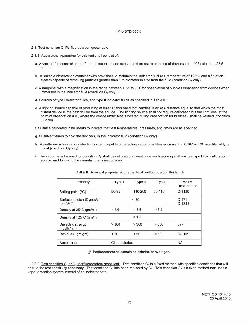
TABLE II. Physical property requirements of perfluorocarbon fluids. 1/
Property Type I Type II Type III ASTM test method
Boiling point (C) 50-95 140-200 50-110 D-1120
Surface tension (Dynes/cm) at 25C
< 20
D-971 D-1331
Density at 25C (gm/ml) > 1.6 > 1.6 > 1.6
Density at 125C (gm/ml) > 1.5
Dielectric strength (volts/mil)
> 300 > 300 > 300 877
Residue (µgm/gm) < 50 < 50 < 50 D-2109
Appearance Clear colorless NA
1/ Perfluorocarbons contain no chlorine or hydrogen.
2.3.2 Test condition C1 or C3, perfluorocarbon gross leak. Test condition C1 is a fixed method with specified conditions that will ensure the test sensitivity necessary. Test condition C2 has been replaced by C1. Test condition C3 is a fixed method that uses a vapor detection system instead of an indicator bath.
MIL-STD-883K
METHOD 1014.15 25 April 2016
16
2.3.3 Procedure applicable to fixed (C1) method. The devices shall be placed in a vacuum/pressure chamber and the pressure
reduced to 5 torr or less and maintained for 30 minutes minimum. The vacuum cycle may be omitted for packages with an internal volume > 0.1 cm3. A sufficient amount of type I detector fluid shall be admitted to cover the devices. When the vacuum cycle is performed, the fluid will be admitted after the minimum 30 minute period but before breaking the vacuum. The devices shall then be pressurized in accordance with Table III. When the pressurization period is complete the pressure shall be released and the devices removed from the chamber without being removed from a bath of detector fluid for greater than 20 seconds. A holding bath may be another vessel or storage tank. When the devices are removed from the bath they shall be dried for 2 ±1 minutes in air prior to immersion in type II indicator fluid, which shall be maintained at 125C ±5C. The devices shall be immersed with the uppermost portion at a minimum depth of 2 inches below the surface of the indicator fluid, one at a time or in such a configuration that a single bubble from a single device out of a group under observation may be clearly observed as to its occurrence and source. The device shall be observed against a dull, nonreflective black background though the magnifier, while illuminated by the lighting source, from the instant of immersion until, expiration of a 30-second minimum observation period, unless rejected earlier.
For packages greater than 5 grams, the effects of package thermal mass shall be determined by evaluating each package family with known leakers and measuring the time for bubbles to be observed. If the evaluation time exceeds the 30 seconds required for the observation time, then the observation time shall be extended to take into account the package thermal mass effect. Alternate methods may be used to meet this intent provided the method is documented and made available to the preparing or acquiring activity upon request.
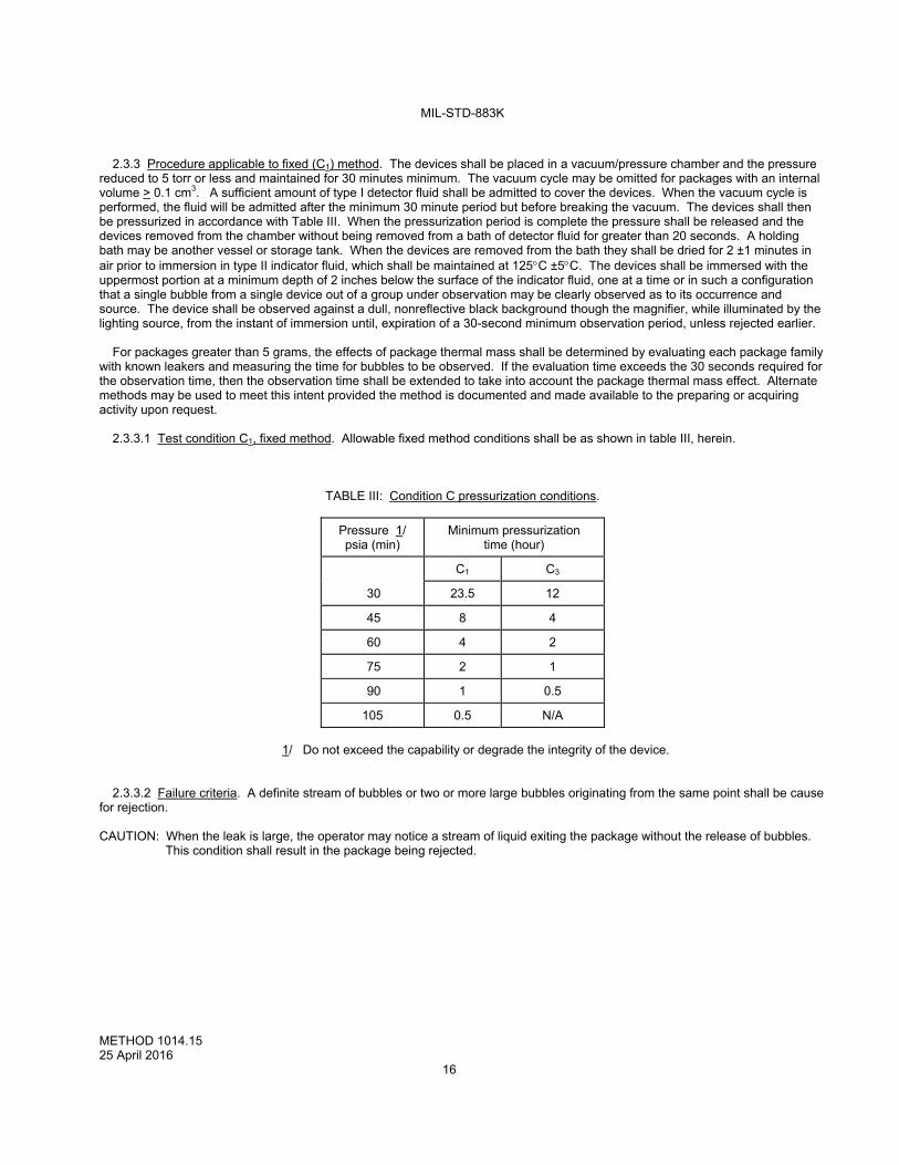
2.3.3.1 Test condition C1, fixed method. Allowable fixed method conditions shall be as shown in table III, herein.
TABLE III: Condition C pressurization conditions.
Pressure 1/ psia (min)
Minimum pressurization time (hour)
C1 C3
30 23.5 12
45 8 4
60 4 2
75 2 1
90 1 0.5
105 0.5 N/A
1/ Do not exceed the capability or degrade the integrity of the device.
2.3.3.2 Failure criteria. A definite stream of bubbles or two or more large bubbles originating from the same point shall be cause for rejection. CAUTION: When the leak is large, the operator may notice a stream of liquid exiting the package without the release of bubbles.
This condition shall result in the package being rejected.
MIL-STD-883K
METHOD 1014.15 25 April 2016
17
2.3.4 Test condition C3, perfluorocarbon vapor detection.
2.3.4.1 Procedure. The devices shall be placed in a vacuum/pressure chamber and the pressure reduced to 5 torr or less and maintained for 30 minutes minimum. A sufficient amount of type I detector fluid shall be admitted to the pressure chamber to cover the devices. The fluid shall be admitted after the 30 minute minimum vacuum period but before breaking the vacuum. The devices shall then be pressurized in accordance with Table III. Upon completion of the pressurization period, the pressure shall be released, the devices removed from the pressure chamber without being removed from a bath of detector fluid for more than 20 seconds and then retained in a bath of perfluorocarbon fluid. When the devices are removed from the fluid they shall be air dried for a minimum of 20 seconds and a maximum of 5 minutes prior to the test cycle. If the type I detector fluid has a boiling point of less than 80C, the maximum drying time shall be 3 minutes.
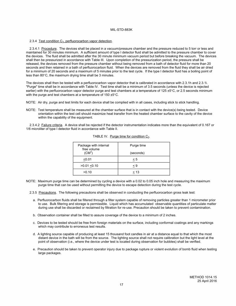
The devices shall then be tested with a perfluorocarbon vapor detector that is calibrated in accordance with 2.3.1h and 2.3.1i. "Purge" time shall be in accordance with Table IV. Test time shall be a minimum of 3.5 seconds (unless the device is rejected earlier) with the perfluorocarbon vapor detector purge and test chambers at a temperature of 125 ±5C, or 2.5 seconds minimum with the purge and test chambers at a temperature of 150 ±5C. NOTE: Air dry, purge and test limits for each device shall be complied with in all cases, including stick to stick handling.
NOTE: Test temperature shall be measured at the chamber surface that is in contact with the device(s) being tested. Device
orientation within the test cell should maximize heat transfer from the heated chamber surface to the cavity of the device within the capability of the equipment.
2.3.4.2 Failure criteria. A device shall be rejected if the detector instrumentation indicates more than the equivalent of 0.167 or
1/6 microliter of type I detector fluid in accordance with Table II.
TABLE IV. Purge time for condition C3.
Package with internal Purge time free volume (CM3) (seconds)
<0.01 < 5
>0.01 <0.10 < 9
>0.10 < 13
NOTE: Maximum purge time can be determined by cycling a device with a 0.02 to 0.05 inch hole and measuring the maximum
purge time that can be used without permitting the device to escape detection during the test cycle.
2.3.5 Precautions. The following precautions shall be observed in conducting the perfluorocarbon gross leak test:
a. Perfluorocarbon fluids shall be filtered through a filter system capable of removing particles greater than 1 micrometer prior to use. Bulk filtering and storage is permissible. Liquid which has accumulated observable quantities of particulate matter during use shall be discarded or reclaimed by filtration for re-use. Precaution should be taken to prevent contamination.
b. Observation container shall be filled to assure coverage of the device to a minimum of 2 inches. c. Devices to be tested should be free from foreign materials on the surface, including conformal coatings and any markings
which may contribute to erroneous test results. d. A lighting source capable of producing at least 15 thousand foot candles in air at a distance equal to that which the most
distant device in the bath will be from the source. The lighting source shall not require calibration but the light level at the point of observation (i.e., where the device under test is located during observation for bubbles) shall be verified.
e. Precaution should be taken to prevent operator injury due to package rupture or violent evolution of bomb fluid when testing
large packages.
MIL-STD-883K
METHOD 1014.15 25 April 2016
18
2.4 Test condition for optical leak test, (C4 , C4 and C5).
2.4.1 Application. Optical Leak Test (OLT) applies to individual devices and to devices mounted on printed circuit boards or
higher level assemblies. The operation for the OLT system is based on the ability to deflect the lid or package. The candidate package shall have a lid stiffness to deflect at least 0.005 microns/psi minimum. These test conditions are valid for lidded devices constructed of metallic, ceramic or other materials which result in measurable deflection of the lid over time as a result of pressure being applied. Generally, Helium is used as the pressure medium. Apparatus required shall consist of suitable pressure or vacuum/pressure chamber with an integral interferometry leak detector. The optical leak detector shall be preset and properly calibrated for an equivalent standard leak rate sensitivity sufficient to detect leakage to the required levels stated in Table VII of paragraph 3. Leak rate is determined by the change in internal pressure of the package of a known internal free volume over a known period of time. When this is normalized to one atmosphere pressure (He) then divided by the test duration and multiplied by the internal free volume, OL (atm-cm3/sec)is determined. The leak rate would be denoted as OLair for air or CDA (clean dry air), OLN2 for Nitrogen, or OLHe for Helium. The conversion factors for these gases are listed in 1.1.c. If the test gas is air then no conversion is necessary and the OLT output can be directly compared to the test limits listed in Table VII. Note: Prior to performing optical gross/fine leak testing, the test designer will need to know the structural limits of the package.
Extreme pressure/vacuum may cause damage to some devices. The test designer will need to design the test conditions around such limitations.
2.4.2 Apparatus. The apparatus required for test conditions C4, C4 and C5 optical leak test shall be as follows:
a. A laser interferometer to measure submicron lid deflection of one or more devices in response to a pressure change. b. A chamber to provide a controlled pressure of up to 90 psia. c. A means of measuring and inducing a small controlled pressure change and electronically calibrating the induced pressure
change to lid deflection for each device simultaneously in order to determine the lid stiffness in microns per psi or equivalent units for each device.
d. A means of tracking the lid movement of each device simultaneously over time. e. Processing electronics capable of using the measured lid position at the beginning and end of the test and the calibrated
stiffness (c) to determine the change in internal pressure of the device. This change in internal pressure along with internal free volume and test duration is used to obtain leak rates OL.
f. An absolute pressure sensor installed that automatically accounts for changes in barometric pressure. g. A temperature sensor (thermocouple) that is used for temperature variations for the Temperature Compensation Factor
(TCF). h. A heater that is used during the initial device profile set up only, for determining the Temperature Compensation Factor
(TCF).
2.4.3 Apparatus initial setup. The optical gross/fine leak test equipment requires unique test parameters for each device type. .
Package set up and calibration shall be performed using two or more devices with leak rates less than the test limits in Table VII. These set up devices will be used prior to production testing to determine if the optical leak tester can be used to test this specific package type and also to determine the specific parameters, Pa, T, and nominal lid stiffness for production testing. Pa and T are fixed values such that the test sensitivity is less than the test limits. Pa shall be the same pressure used during test and T is the minimum time required to achieve passing leak rates. The measured lid stiffness for each device (unique serial number) will be used to calculate the leak rate. This initial step can be skipped if the test set up information for this specific package type and geometry has already been previously determined, documented, and maintained in the system. Note: Do not test the packages within 30 minutes of seam sealing or baking. The packages should be at the same ambient
temperature as the leak tester. 2.4.4 Process monitoring. A group of “system check devices” shall be used for system operation verification at the beginning
and end of each work shift. There shall be at least two devices that exhibit a leak rate greater than the test limits in table VII and at least two more devices with leak rates greater than the test limits in Table VII. A leak rate log of the system check devices shall be maintained and made available to the qualifying activity.
*
*
*
*
*
MIL-STD-883K
METHOD 1014.15 25 April 2016
19
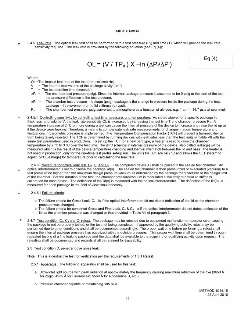
2.4.5 Leak rate. The optical leak test shall be performed with a test pressure (Pa) and time (T), which will provide the leak rate sensitivity required. The leak rate is provided by the following equation (see Eq (4)):
OL = (V / TPa ) X –ln (∆Pf/∆Pi)
Where:
OL = The implied leak rate of the test (atm-cm3/sec He). V = The internal free volume of the package cavity (cm3). T = The test duration time (seconds). ∆Pi = The chamber test pressure (psig). Since the internal package pressure is assumed to be 0 psig at the start of the test,
the pressure difference is the test pressure. ∆Pf = The chamber test pressure – leakage (psig). Leakage is the change in pressure inside the package during the test. Leakage = lid movement (um) / lid stiffness (um/psi). Pa = The chamber test pressure, psig converted to atmosphere as a function of altitude, e.g. 1 atm = 14.7 psia at sea level.
2.4.5.1 Controlling sensitivity by controlling test time, pressure, and temperature. As stated above, for a specific package lid thickness, and volume V, the leak rate sensitivity OL is increased by increasing the test time T and chamber pressure Pa. A temperature increase of 2 °C or more during a test can cause the internal pressure of the device to increase and raise the lid up as if the device were leaking. Therefore, a means to compensate leak rate measurements for changes in room temperature and fluctuations in barometric pressure is implemented. The Temperature Compensation Factor (TCF) will prevent a hermetic device from being falsely rejected. The TCF is determined by running devices with leak rates less than the test limits in Table VII with the same test parameters used in production. To set up the TCF for a new part type, a heater is used to raise the chamber temperature by 2 °C to 3 °C over the test time. The ∆PD (change in internal pressure of the device, also called leakage) will be measured which is the result of the device temperature changing and thermal mismatch between the lid and base. The heater is not used in production, only for the one-time test profile set-up run. The units for TCF are psi / °C and allows the OLT system to adjust ∆PD (leakage) for temperature prior to calculating the leak rate.
2.4.6 Procedure for optical leak test, C4 , C4 and C5. The completed device(s) shall be placed in the sealed test chamber. An
optical interferometer is set to observe the package lid(s). The sealed test chamber is then pressurized or evacuated (vacuum) to a test pressure no higher than the maximum design pressure/vacuum as determined by the package manufacturer or the design limit of the chamber. For the duration of the test, the chamber pressure/vacuum is modulated sufficiently to obtain lid stiffness calibration for each device. The deflection of the lid(s) is measured with the optical interferometer. The deflection of the lid(s), is measured for each package in the field of view simultaneously.
2.4.6.1 Failure criteria.
a. The failure criteria for Gross Leak, C4 , is if the optical interferometer did not detect deflection of the lid as the chamber pressure was changed.
b. The failure criteria for combined Gross and Fine Leak, C4 & C5 , is if the optical interferometer did not detect deflection of the lid as the chamber pressure was changed or that provided in Table VII of paragraph 3.
2.4.7 Test condition C4, C4 and C5 retest. The package may be retested due to equipment malfunction or operator error causing the package to not be properly tested, or the test not being completed. If approved by the qualifying activity, retest may be performed due to other conditions and shall be documented accordingly. The proper wait time before performing a retest shall ensure the internal package pressure has equalized with the outside pressure. This proper wait time shall be determined through repeated testing of a fine leaking package and the data shall be available to the acquiring or qualifying activity upon request. The retesting shall be documented and records shall be retained for traceability. 2.5 Test condition D, penetrant dye gross leak. Note: This is a destructive test for verification per the requirements of 1.3.1 Retest.
2.5.1 Apparatus. The following apparatus shall be used for this test:
a. Ultraviolet light source with peak radiation at approximately the frequency causing maximum reflection of the dye (3650 Å for Zyglo; 4935 Å for Fluorescein; 5560 Å for Rhodamine B, etc.).
b. Pressure chamber capable of maintaining 105 psia.
Eq (4)
*
*
*
*
*
MIL-STD-883K
METHOD 1014.15 25 April 2016
20
c. Solution of fluorescent dye (such as Rhodamine B, Fluorescein, Dye-check, Zyglo, FL- 50, or equivalent) mixed in
accordance with the manufacturer's specification. d. A magnifier with a magnification in the range between 1.5X to 30X for dye observation.
2.5.2 Test condition D, penetrant dye gross leak. The pressure chamber shall be filled with the dye solution to a depth sufficient
to completely cover all the devices. The devices shall be placed in the solution and the chamber pressurized at 105 psia minimum for 3 hours minimum. For device packages which will not withstand 105 psia, 60 psia minimum for 10 hours may be used. The devices shall then be removed and carefully washed, using a suitable solvent for the dye used, followed by an air-jet dry. Remove the lid from the device. The devices shall then be immediately examined under the magnifier using an ultraviolet light source of appropriate frequency.
2.5.2.1 Failure criteria. Any evidence of dye penetration into the device cavity shall constitute a failure.
2.6 Test condition E, weight gain gross leak.
2.6.1 Apparatus. Apparatus for this test shall consist of:
a. A vacuum/pressure chamber for the evacuation and subsequent pressure bombing of devices up to 90 psia up to 10 hours.
b. An analytical balance capable of weighing the devices accurately to 0.1 milligram.
c. A source of type III detector fluid as specified in Table II.
d. A filtration system capable of removing particles greater than 1 micrometer in size from the perfluorocarbon fluid.
e. Suitable calibrated instruments to measure test pressures and times.
2.6.2 Procedure. The devices shall be placed in an oven at 125C for 1 hour minimum, after which they shall be allowed to cool to room ambient temperature. Each device shall be weighed and the initial weight recorded or the devices may be categorized into cells as follows. Devices having a volume of <0.01 cm3 shall be categorized in cells of 0.5 milligram increments and devices with volume >0.01 cm3 shall be categorized in cells of 1.0 milligram increments. The devices shall be placed in a vacuum/pressure chamber and the pressure reduced to 5 torr and maintained for 1 hour except that for devices with an internal free volume >0.1 cm3, this vacuum cycle may be omitted. A sufficient amount of type III detector fluid shall be admitted to the pressure chamber to cover the devices. When the vacuum cycle is performed, the fluid shall be admitted after the 1-hour period but before breaking the vacuum. The devices shall then be pressurized to 75 psia minimum except that 90 minimum psia shall be used when the vacuum cycle has been omitted. The pressure shall be maintained for 2 hours minimum. If the devices will not withstand the 75 psia test pressure, the pressure may be lowered to 45 psia minimum with the vacuum cycle and the pressure maintained for 10 hours minimum.
Upon completion of the pressurization period, the pressure shall be released and the devices removed from the pressure chamber and retained in a bath of the perfluorocarbon fluid. When the devices are removed from the fluid they shall be air dried for 2 ±1 minutes prior to weighing. Transfer the devices singly to the balance and determine the weight or weight category of each device. All devices shall be tested within 4 minutes following removal from the fluid. The delta weight shall be calculated from the record of the initial weight and the post weight of the device. Devices which were categorized shall be separated into two groups, one group which shall be devices which shifted one cell or less and the other group which shall be devices which shifted more than one cell.
2.6.3 Failure criteria. A device shall be rejected if it gains 1.0 milligram or more and has an internal volume of <0.01 cm3 or if it gains 2.0 milligrams or more and has an internal volume of > 0.01 cm3. If the devices are categorized, any device which gains enough weight to cause it to shift by more than one cell shall be considered a reject. A device which loses weight of an amount which if gained would cause the device to be rejected may be retested after it is baked at 125C for a period of 8 hours.
MIL-STD-883K
METHOD 1014.15 25 April 2016
21
2.7 Test condition G1, radioisotope thermal leak test.
2.7.1 Application. This test is for the evaluation of package hermetic integrity at elevated temperature. It is intended to verify
that the package structural design will maintain hermetic integrity at elevated temperatures. Devices to be evaluated in this thermal leak test shall be packages that should not have been subjected to any prior liquid immersion testing (e.g. thermal shock, bubble test). The devices to be tested for thermal leakage shall first be subjected to a fine and dry gross leak test, to at least the sensitivity requirement for that package in the standard, and the hermeticity to that sensitivity, establishing the package is hermetic at ambient temperature.
2.7.2 Apparatus. Apparatus for this test shall consist of the following:
a. Radioactive tracer gas pressurization console containing Kr85/air mixture. A Kr85 pressure/vacuum thermal test chamber capable of evacuation and pressurization at temperatures, and thermal cycling from ambient temperature to maximum temperature of the test desired while maintaining Kr85/air pressure.
b. Counting station as in paragraph 2.2.1b excluding Tunnel Scintillation Crystal. c. A tracer gas as in paragraph 2.2.1c.
2.7.3 Testing parameters. Prior to the thermal-radioisotope test, the devices shall be pre-tested to the sensitivity requirement for
that package in the standard. The bombing pressure and soak time for the pre-test shall be established for the package following 2.2.5.1.
2.7.3.1 Determination of counting efficiency (k). Shall be as in 2.2.4 2.7.3.2 Evaluation of surface sorption. Shall be as in 2.2.5.4 2.7.4 Procedures. The devices shall be placed in the radioactive tracer gas thermal-pressurization chamber. The tank shall be
evacuated to 0.5 torr. The devices shall be subjected to a pressure of Kr85/air mixture at a pressure of 60 psia, (typical), or a minimum of 30 psia (dependent upon the structural compatibility of the package).
2.7.4.1 Thermal test. The devices are placed in the thermal/pressure chamber and pressurized with Kr85/air mixture to the
pressure established in 2.2.5. The chamber is then heated to a temperature in the range of 100ºC to 125ºC and maintained at the elevated temperature for a minimum of 10 minutes. The heating rate should be 1ºC per minute minimum or as specified. The temperature is then returned to ambient, at which time the Kr85 is returned to storage and the devices are removed from the thermal/pressure chamber and measured at the scintillation crystal detection station for any Kr85 gas trapped within the devices. Device encapsulations that come under the requirements of 2.2.6 shall be exposed to ambient air for a time not less than the wait time determined by 2.2.5.4. In no case will the time between removal from the pressurization chamber and measurement exceed 60 minutes. This test is frequently applied to devices that have indicated leakage at ambient temperature in order to establish if they open to a larger leak rate at temperature.
2.7.5 Failure criteria. This test is a “Go-No-Go” test to detect packages that ‘open-up’, or become non-hermetic at elevated
temperature. The detection of a measurable amount of Kr85, (greater than 500 c/m above ambient background), within the part after exposure to Kr85 pressure at temperature indicates a “thermal-reject”, (hermetic failure at elevated temperature).
Note: A thermal reject may be placed in a vacuum oven and the temperature increased for 10 minutes minimum, at 10ºC intervals,
and the device removed to measure the Kr85 content after each 10ºC increase, until the temperature is reached at which the Kr85 reading begins to decrease, indicating the temperature at which the device opened during pressurization. This will indicate the approximate temperature at which the device is leaking, (or increasing its leak rate).
MIL-STD-883K
METHOD 1014.15 25 April 2016
22
2.8 Test condition CH, cumulative helium leak test.
2.8.1 CH1 and CH2 combined fine/gross leak. Test Conditions CH1 “fixed” method and CH2 “flexible” method expand the range
of He fine leak to include the gross leak range and require the same test conditions using the Cumulative Helium Leak Detector (CHLD) System. Test condition Z utilizes Helium to measure gross leaks and a selection of tracer gasses in addition to Helium for the fine leak measurement. 2.8.2 Apparatus. The apparatus of the CHLD System. 2.8.2.1 Calibration Leak Standard. The apparatus for this procedure uses a mass spectrometer as in test condition A1 except that the optimum Calibration Leak Standard is 5 x 10⁻¹⁰ atm cm3/sec and, since the slope of the accumulated Helium is a linear function, measurements beyond 10-12 are achievable if the calibration slope ratio to the background slope is greater than 100. A Helium Validation Standard of 5 x 10-12 shall be used to validate the sensitivity and linearity of the lower leak rate range and a 1 x 10⁻⁸ Helium leak standard used for the higher range. The leak rate standards shall be recalibrated at least every five years.
2.8.2.1.1 Pumping system. The leak detector indicator shall be calibrated using a diffusion-type calibrated standard leak at least once every working shift. In addition, the test apparatus for CH1 and CH2 utilizes a specialized pumping system that enables the volume of Helium released to be measured as well as the rate of change or “slope” of the Helium. The leak rate is determined from the slope measurement for fine leaks and from the volume for gross leaks:
2.8.2.1.2 Chamber volume. The volume of the test chamber used for leak rate measurement should be held to the minimum size practical, since a ratio of the chamber dead volume (Vc) to the device internal volume (Vd) of greater than 100 will reduce the sensitivity limits when detecting gross leaks. The maximum ratio of test chamber dead volume to device internal volume Vc/Vd must be established for individual part testing and batch testing to insure a gross leak amplitude will be detected with a signal to background ratio of at least 3 to one. This ratio is a function of the Helium content of the purge gas as well as the internal volume and number of devices to be batch tested.
2.8.2.1.3 Purge pump. A purge gas with a Helium content less than 1 ppm.
*
MIL-STD-883K
METHOD 1014.15 25 April 2016
23
2.8.3. Procedure applicable to CH1 "fixed" and CH2 "flexible" methods. The completed devices(s) shall be placed in a sealed
chamber per conditions A1 and A2 as specified in 2.1.2.1. (The evacuation pressure if used shall be documented). The pressure shall then be relieved (an optional air wash may be applied or other technique to reduce the effects of surface sorption as specified in 2.8.3.2 can be used) and each specimen transferred to another chamber or chambers which are connected to the evacuating system and a mass-spectrometer-type leak detector. When the chamber is evacuated, any tracer gas which was previously forced into the specimen will thus be drawn out and indicated by the leak detector as a measured leak rate (R). The number of devices removed from pressurization for leak testing shall be limited such that the test of the last device can be completed within the dwell times listed in Table 1). Note: The flexible method CH2 shall be used unless otherwise specified in the acquisition document, purchase order, or contract.
2.8.3.1 Dwell Time. Dwell time for the CH1 and CH2 methods shall be 0.5 hour for packages having internal free volumes ≤ 0.05 cm3 and 1 hour for packages having internal free volumes > 0.05 cm3. For packages with internal free volumes > 0.05 cm3, the maximum dwell time t2 may be increased up to a maximum of 4 hours. Prior to increasing dwell times, the manufacturer or test facility shall qualify a procedure for each package type to ensure there are no gross leak escapes at the maximum dwell time proposed. This procedure shall address any technique used to mitigate surface sorption as stated in 2.8.3.3.
2.8.3.2. Evaluation of surface sorption and wait time. All device encapsulations consisting of glass, metal, and ceramic or
combinations thereof including coatings and external sealants, shall be evaluated for surface sorption of the leak test tracer gas (such as Helium) before establishing the leak test procedures and parameters. Devices susceptible to surface sorption cannot be tested until the surface sorption has dissipated to ≤0.5 R1. This is defined as the wait time.
The wait time is determined by testing lidded and, if possible, delidded representative samples at the proposed bombing
conditions. The R measurement and time duration for each lidded device shall be monitored until the R measurement falls to ≤0.5 R1. Sorption may vary with pressure and time of exposure so that some trial may be required before satisfactory exposure values are obtained. If the wait time does not yield adequate time to test parts within the required dwell time as specified in 2.8.3.1, then one or more of the following can be implemented: (1) use the mitigation of surface sorption strategy as described in 2.8.3.3; (2) use the procedure described in 2.8.3.1 to increase the dwell time; or (3) use the flexible method CH2 to increase R1 and to shorten the wait time.
2.8.3.3. Mitigation of surface sorption. Three techniques (ventilation in ambient air, dry gas wash, and thermal bake out) can be
used to reduce the wait time as established in 2.8.3.2. The technique utilized depends on the tracer gas sorption characteristics of the particular device to be leak tested and the sensitivity of the leak detector system. Typically, a shorter Helium bomb time results in less Helium sorption and a shorter wait time; however; a shorter bomb time yields a much smaller R1 value, which may exceed the sensitivity of the CHLD system. Prior to implementing a mitigation strategy, the proposed strategy shall be qualified for each package type to establish the required sensitivity is not diminished.
2.8.3.3.1 Ventilation in ambient air. Many devices are leak tested without regard for surface effects, since the time it takes to remove the devices from the Helium bomb and bring them to the leak detector is sufficient to reduce surface effects to levels below the Helium (R1) test limit. In the past, devices were regularly allowed to sit in the open in a well ventilated area for 15 to 30 minutes prior to conducting a leak test.
2.8.3.3.2 Dry gas wash. The practice of blowing a dry gas on the devices prior to leak testing to reduce the effects of surface sorption is most effective on devices which are contaminated with surface moisture or other high vapor pressure solvents such as IPA. Some ceramic devices with low porosity respond favorably to this blowing procedure. The CHLD test method provides leak test measurements through the gross leak range. In the worst case, only atmospheric air is present in the device. If dry Nitrogen is used to blow off surface adsorption, there is a potential to displace the room air in a gross leaker with Nitrogen (Note: most commercial Nitrogen contains at least 1.0 ppm Helium where as room air contains at least 5.0 ppm Helium) which will reduce the sensitivity to a gross leak. If a dry gas is used, dry atmospheric air is preferred for the CHLD test method.
2.8.3.3.3 Thermal bake out. Heating devices after bombing to reduce Helium desorption is best done in an ambient air environment, again to reduce the potential for displacing the ambient Helium from a gross leaker. This technique is most effective for ceramic devices and devices with glass seals which have a high permeation rate for Helium. Surface moisture, which is present from exposure to high humidity levels found in ESD work areas, contributes strongly in each case to desorption rates. Various temperatures can be used for this desorption process, however, enough thermal energy must be given to the surface adsorbed water molecules to break their polar bond which occurs prolifically at temperatures above 125ºC. Heating works well for optical devices which have either plastic or glass lenses attached to the outer surface of the device or include fiber optic interfaces. Currently, it is sufficient to simply bake devices on an open hot plate for 20 – 30 minutes at 125ºC to mitigate any sorption of any tracer gas.
*
* *
*
*
*
*
*
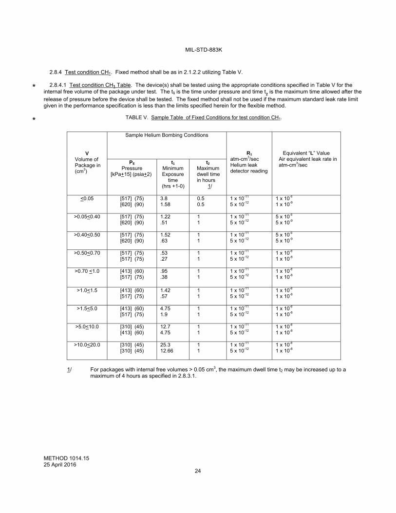
MIL-STD-883K
METHOD 1014.15 25 April 2016
24
2.8.4 Test condition CH1. Fixed method shall be as in 2.1.2.2 utilizing Table V.
2.8.4.1 Test condition CH1 Table. The device(s) shall be tested using the appropriate conditions specified in Table V for the
internal free volume of the package under test. The t1 is the time under pressure and time t2 is the maximum time allowed after the release of pressure before the device shall be tested. The fixed method shall not be used if the maximum standard leak rate limit given in the performance specification is less than the limits specified herein for the flexible method.
TABLE V. Sample Table of Fixed Conditions for test condition CH1.
V Volume of Package in (cm3)
Sample Helium Bombing Conditions
R1
atm-cm3/sec Helium leak detector reading
Equivalent “L” Value Air equivalent leak rate in atm-cm3/sec
PE Pressure
[kPa+15] (psia+2)
t1 Minimum Exposure
time (hrs +1-0)
t2 Maximum dwell time in hours
1/
<0.05
[517] (75) [620] (90)
3.8 1.58
0.5 0.5
1 x 10-11
5 x 10-12
1 x 10⁻⁹ 1 x 10⁻⁹
>0.05<0.40 [517] (75) [620] (90)
1.22 .51
1 1
1 x 10-11
5 x 10-12
5 x 10⁻⁹ 5 x 10⁻⁹
>0.40<0.50 [517] (75) [620] (90)
1.52 .63
1 1
1 x 10-11
5 x 10-12
5 x 10⁻⁹ 5 x 10⁻⁹
>0.50<0.70 [517] (75) [517] (75)
.53
.27
1 1
1 x 10-11
5 x 10-12
1 x 10⁻⁸ 1 x 10⁻⁸
>0.70 <1.0 [413] (60) [517] (75)
.95
.38
1 1
1 x 10-11
5 x 10-12
1 x 10⁻⁸ 1 x 10⁻⁸
>1.0<1.5 [413] (60) [517] (75)
1.42 .57
1 1
1 x 10-11
5 x 10-12
1 x 10⁻⁸ 1 x 10⁻⁸
>1.5<5.0 [413] (60) [517] (75)
4.75 1.9
1 1
1 x 10-11
5 x 10-12
1 x 10⁻⁸ 1 x 10⁻⁸
>5.0<10.0 [310] (45) [413] (60)
12.7 4.75
1 1
1 x 10-11
5 x 10-12
1 x 10⁻⁸ 1 x 10⁻⁸
>10.0<20.0 [310] (45) [310] (45)
25.3 12.66
1 1
1 x 10-11
5 x 10-12
1 x 10⁻⁸ 1 x 10⁻⁸
1/ For packages with internal free volumes > 0.05 cm3, the maximum dwell time t2 may be increased up to a
maximum of 4 hours as specified in 2.8.3.1.
*
*
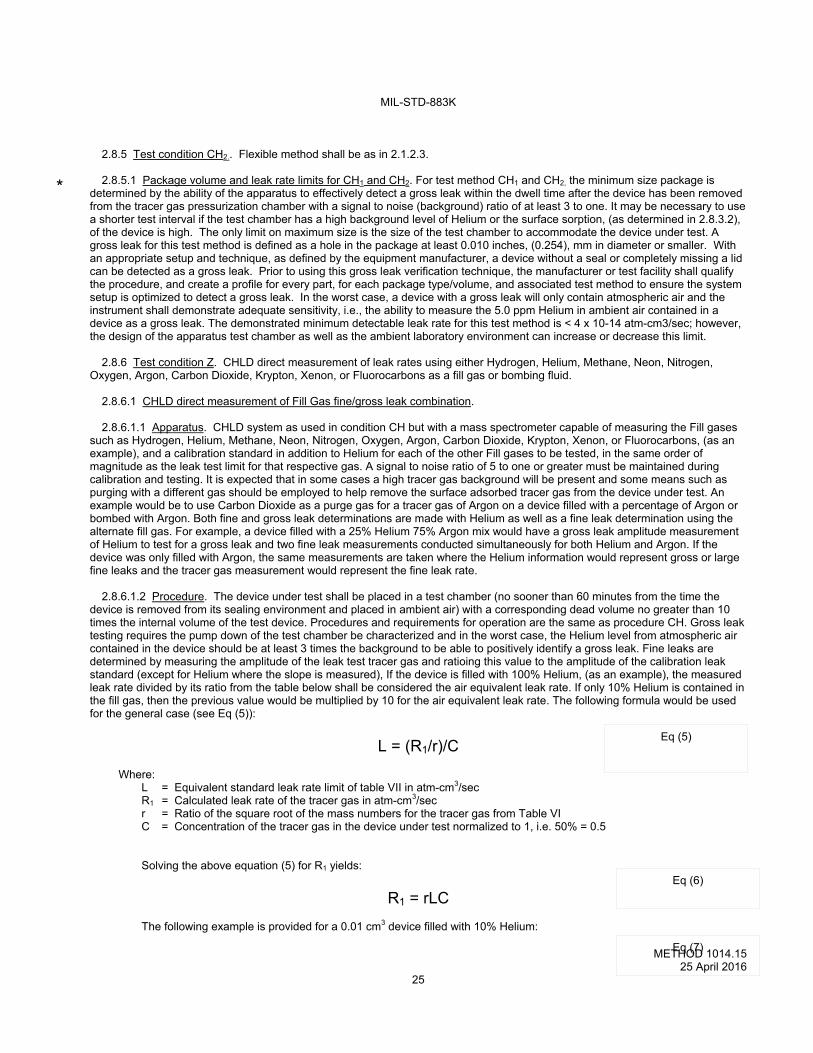
MIL-STD-883K
METHOD 1014.15 25 April 2016
25
2.8.5 Test condition CH2.. Flexible method shall be as in 2.1.2.3. 2.8.5.1 Package volume and leak rate limits for CH1 and CH2. For test method CH1 and CH2, the minimum size package is
determined by the ability of the apparatus to effectively detect a gross leak within the dwell time after the device has been removed from the tracer gas pressurization chamber with a signal to noise (background) ratio of at least 3 to one. It may be necessary to use a shorter test interval if the test chamber has a high background level of Helium or the surface sorption, (as determined in 2.8.3.2), of the device is high. The only limit on maximum size is the size of the test chamber to accommodate the device under test. A gross leak for this test method is defined as a hole in the package at least 0.010 inches, (0.254), mm in diameter or smaller. With an appropriate setup and technique, as defined by the equipment manufacturer, a device without a seal or completely missing a lid can be detected as a gross leak. Prior to using this gross leak verification technique, the manufacturer or test facility shall qualify the procedure, and create a profile for every part, for each package type/volume, and associated test method to ensure the system setup is optimized to detect a gross leak. In the worst case, a device with a gross leak will only contain atmospheric air and the instrument shall demonstrate adequate sensitivity, i.e., the ability to measure the 5.0 ppm Helium in ambient air contained in a device as a gross leak. The demonstrated minimum detectable leak rate for this test method is < 4 x 10-14 atm-cm3/sec; however, the design of the apparatus test chamber as well as the ambient laboratory environment can increase or decrease this limit.
2.8.6 Test condition Z. CHLD direct measurement of leak rates using either Hydrogen, Helium, Methane, Neon, Nitrogen,
Oxygen, Argon, Carbon Dioxide, Krypton, Xenon, or Fluorocarbons as a fill gas or bombing fluid.
2.8.6.1 CHLD direct measurement of Fill Gas fine/gross leak combination.
2.8.6.1.1 Apparatus. CHLD system as used in condition CH but with a mass spectrometer capable of measuring the Fill gases such as Hydrogen, Helium, Methane, Neon, Nitrogen, Oxygen, Argon, Carbon Dioxide, Krypton, Xenon, or Fluorocarbons, (as an example), and a calibration standard in addition to Helium for each of the other Fill gases to be tested, in the same order of magnitude as the leak test limit for that respective gas. A signal to noise ratio of 5 to one or greater must be maintained during calibration and testing. It is expected that in some cases a high tracer gas background will be present and some means such as purging with a different gas should be employed to help remove the surface adsorbed tracer gas from the device under test. An example would be to use Carbon Dioxide as a purge gas for a tracer gas of Argon on a device filled with a percentage of Argon or bombed with Argon. Both fine and gross leak determinations are made with Helium as well as a fine leak determination using the alternate fill gas. For example, a device filled with a 25% Helium 75% Argon mix would have a gross leak amplitude measurement of Helium to test for a gross leak and two fine leak measurements conducted simultaneously for both Helium and Argon. If the device was only filled with Argon, the same measurements are taken where the Helium information would represent gross or large fine leaks and the tracer gas measurement would represent the fine leak rate.
2.8.6.1.2 Procedure. The device under test shall be placed in a test chamber (no sooner than 60 minutes from the time the device is removed from its sealing environment and placed in ambient air) with a corresponding dead volume no greater than 10 times the internal volume of the test device. Procedures and requirements for operation are the same as procedure CH. Gross leak testing requires the pump down of the test chamber be characterized and in the worst case, the Helium level from atmospheric air contained in the device should be at least 3 times the background to be able to positively identify a gross leak. Fine leaks are determined by measuring the amplitude of the leak test tracer gas and ratioing this value to the amplitude of the calibration leak standard (except for Helium where the slope is measured), If the device is filled with 100% Helium, (as an example), the measured leak rate divided by its ratio from the table below shall be considered the air equivalent leak rate. If only 10% Helium is contained in the fill gas, then the previous value would be multiplied by 10 for the air equivalent leak rate. The following formula would be used for the general case (see Eq (5)):
L = (R1/r)/C
Where: L = Equivalent standard leak rate limit of table VII in atm-cm3/sec R1 = Calculated leak rate of the tracer gas in atm-cm3/sec r = Ratio of the square root of the mass numbers for the tracer gas from Table VI C = Concentration of the tracer gas in the device under test normalized to 1, i.e. 50% = 0.5 Solving the above equation (5) for R1 yields:
R1 = rLC
The following example is provided for a 0.01 cm3 device filled with 10% Helium:
Eq (5)
Eq (6)
Eq (7)
*
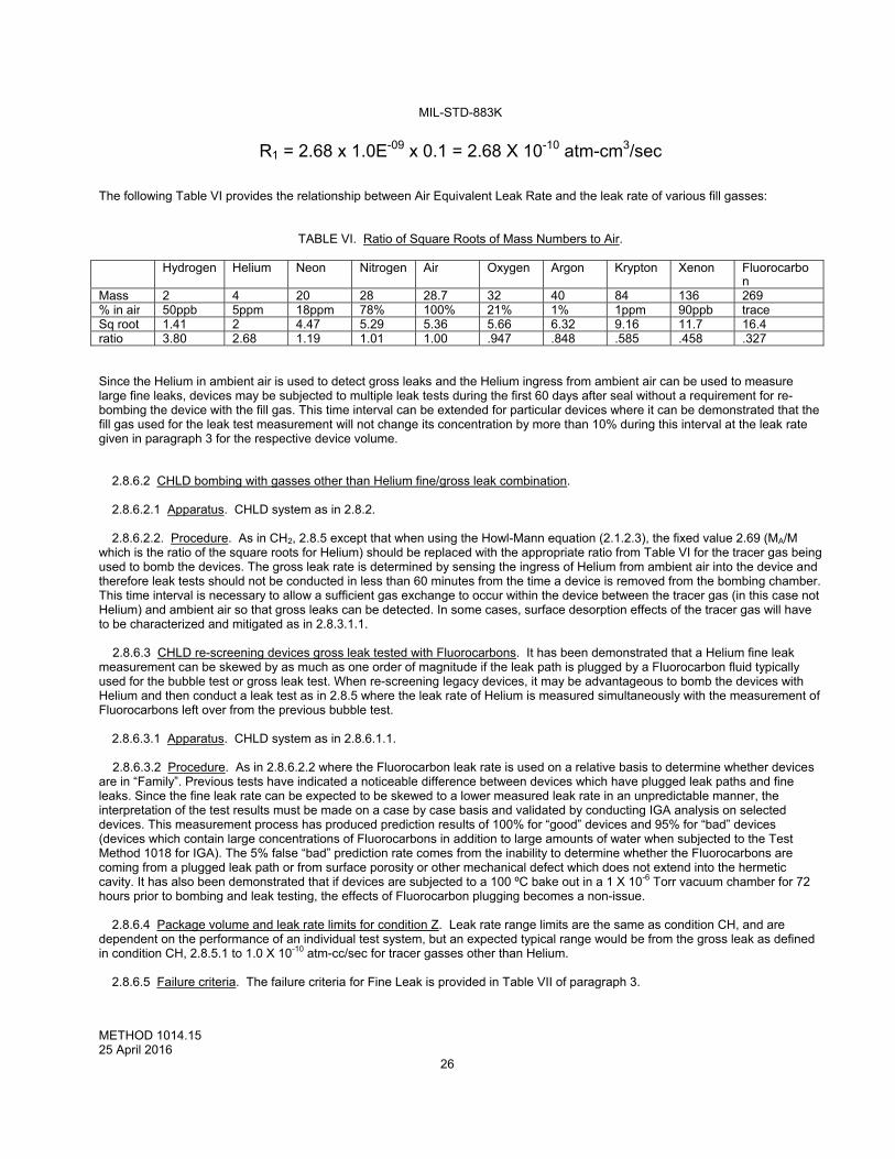
MIL-STD-883K
METHOD 1014.15 25 April 2016
26
R1 = 2.68 x 1.0E-09 x 0.1 = 2.68 X 10⁻¹⁰ atm-cm3/sec
The following Table VI provides the relationship between Air Equivalent Leak Rate and the leak rate of various fill gasses:
TABLE VI. Ratio of Square Roots of Mass Numbers to Air. Hydrogen Helium Neon Nitrogen Air Oxygen Argon Krypton Xenon Fluorocarbo
nMass 2 4 20 28 28.7 32 40 84 136 269% in air 50ppb 5ppm 18ppm 78% 100% 21% 1% 1ppm 90ppb traceSq root 1.41 2 4.47 5.29 5.36 5.66 6.32 9.16 11.7 16.4ratio 3.80 2.68 1.19 1.01 1.00 .947 .848 .585 .458 .327
Since the Helium in ambient air is used to detect gross leaks and the Helium ingress from ambient air can be used to measure large fine leaks, devices may be subjected to multiple leak tests during the first 60 days after seal without a requirement for re-bombing the device with the fill gas. This time interval can be extended for particular devices where it can be demonstrated that the fill gas used for the leak test measurement will not change its concentration by more than 10% during this interval at the leak rate given in paragraph 3 for the respective device volume.
2.8.6.2 CHLD bombing with gasses other than Helium fine/gross leak combination.
2.8.6.2.1 Apparatus. CHLD system as in 2.8.2.
2.8.6.2.2. Procedure. As in CH2, 2.8.5 except that when using the Howl-Mann equation (2.1.2.3), the fixed value 2.69 (MA/M which is the ratio of the square roots for Helium) should be replaced with the appropriate ratio from Table VI for the tracer gas being used to bomb the devices. The gross leak rate is determined by sensing the ingress of Helium from ambient air into the device and therefore leak tests should not be conducted in less than 60 minutes from the time a device is removed from the bombing chamber. This time interval is necessary to allow a sufficient gas exchange to occur within the device between the tracer gas (in this case not Helium) and ambient air so that gross leaks can be detected. In some cases, surface desorption effects of the tracer gas will have to be characterized and mitigated as in 2.8.3.1.1.
2.8.6.3 CHLD re-screening devices gross leak tested with Fluorocarbons. It has been demonstrated that a Helium fine leak measurement can be skewed by as much as one order of magnitude if the leak path is plugged by a Fluorocarbon fluid typically used for the bubble test or gross leak test. When re-screening legacy devices, it may be advantageous to bomb the devices with Helium and then conduct a leak test as in 2.8.5 where the leak rate of Helium is measured simultaneously with the measurement of Fluorocarbons left over from the previous bubble test.
2.8.6.3.1 Apparatus. CHLD system as in 2.8.6.1.1.
2.8.6.3.2 Procedure. As in 2.8.6.2.2 where the Fluorocarbon leak rate is used on a relative basis to determine whether devices are in “Family”. Previous tests have indicated a noticeable difference between devices which have plugged leak paths and fine leaks. Since the fine leak rate can be expected to be skewed to a lower measured leak rate in an unpredictable manner, the interpretation of the test results must be made on a case by case basis and validated by conducting IGA analysis on selected devices. This measurement process has produced prediction results of 100% for “good” devices and 95% for “bad” devices (devices which contain large concentrations of Fluorocarbons in addition to large amounts of water when subjected to the Test Method 1018 for IGA). The 5% false “bad” prediction rate comes from the inability to determine whether the Fluorocarbons are coming from a plugged leak path or from surface porosity or other mechanical defect which does not extend into the hermetic cavity. It has also been demonstrated that if devices are subjected to a 100 ºC bake out in a 1 X 10⁻⁶ Torr vacuum chamber for 72 hours prior to bombing and leak testing, the effects of Fluorocarbon plugging becomes a non-issue.
2.8.6.4 Package volume and leak rate limits for condition Z. Leak rate range limits are the same as condition CH, and are dependent on the performance of an individual test system, but an expected typical range would be from the gross leak as defined in condition CH, 2.8.5.1 to 1.0 X 10⁻¹⁰ atm-cc/sec for tracer gasses other than Helium.
2.8.6.5 Failure criteria. The failure criteria for Fine Leak is provided in Table VII of paragraph 3.
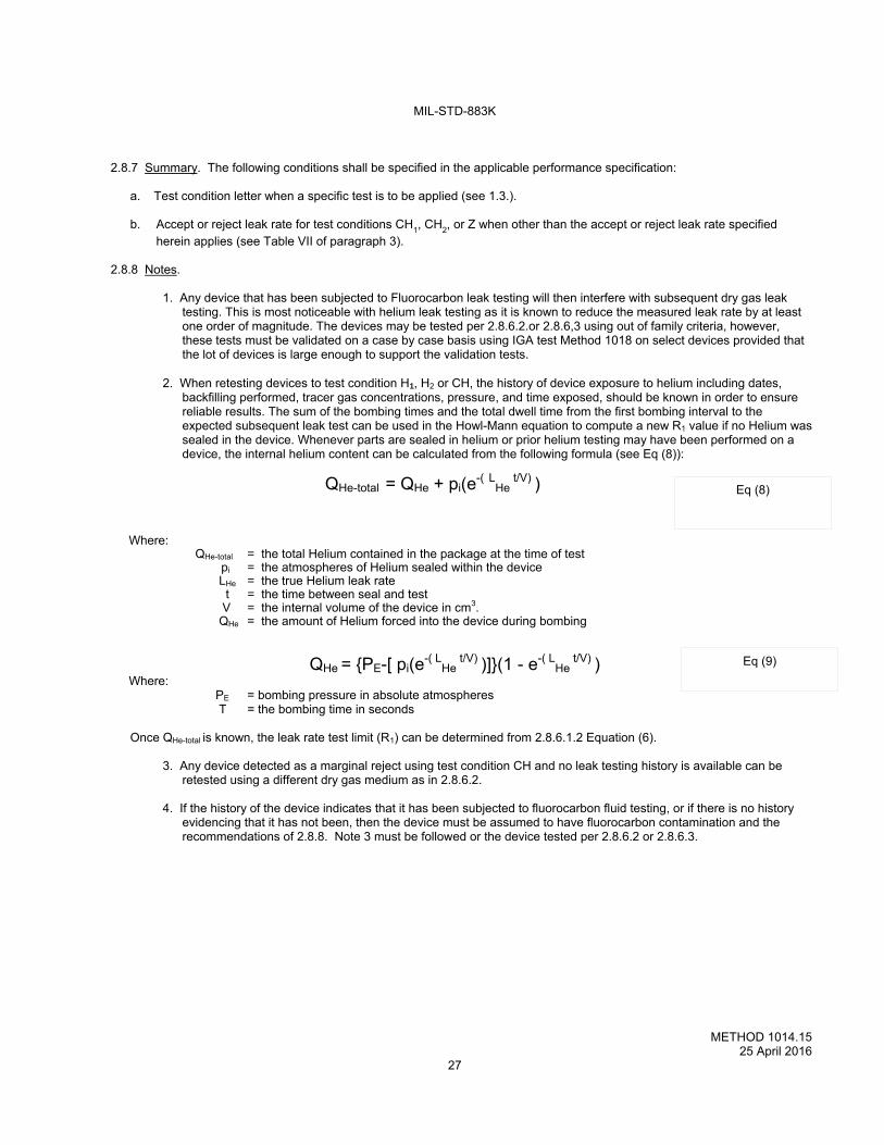
MIL-STD-883K
METHOD 1014.15 25 April 2016
27
2.8.7 Summary. The following conditions shall be specified in the applicable performance specification:
a. Test condition letter when a specific test is to be applied (see 1.3.).
b. Accept or reject leak rate for test conditions CH1, CH2, or Z when other than the accept or reject leak rate specified
herein applies (see Table VII of paragraph 3).
2.8.8 Notes.
1. Any device that has been subjected to Fluorocarbon leak testing will then interfere with subsequent dry gas leak testing. This is most noticeable with helium leak testing as it is known to reduce the measured leak rate by at least one order of magnitude. The devices may be tested per 2.8.6.2.or 2.8.6,3 using out of family criteria, however, these tests must be validated on a case by case basis using IGA test Method 1018 on select devices provided that the lot of devices is large enough to support the validation tests.
2. When retesting devices to test condition H1, H2 or CH, the history of device exposure to helium including dates,
backfilling performed, tracer gas concentrations, pressure, and time exposed, should be known in order to ensure reliable results. The sum of the bombing times and the total dwell time from the first bombing interval to the expected subsequent leak test can be used in the Howl-Mann equation to compute a new R1 value if no Helium was sealed in the device. Whenever parts are sealed in helium or prior helium testing may have been performed on a device, the internal helium content can be calculated from the following formula (see Eq (8)):
QHe-total = QHe + pi(e-( LHe
t/V) ) Where: QHe-total = the total Helium contained in the package at the time of test pi = the atmospheres of Helium sealed within the device LHe = the true Helium leak rate t = the time between seal and test V = the internal volume of the device in cm3. QHe = the amount of Helium forced into the device during bombing
QHe = {PE-[ pi(e-( L
He t/V) )]}(1 - e-( L
He t/V) )
Where: PE = bombing pressure in absolute atmospheres T = the bombing time in seconds
Once QHe-total is known, the leak rate test limit (R1) can be determined from 2.8.6.1.2 Equation (6).
3. Any device detected as a marginal reject using test condition CH and no leak testing history is available can be retested using a different dry gas medium as in 2.8.6.2.
4. If the history of the device indicates that it has been subjected to fluorocarbon fluid testing, or if there is no history
evidencing that it has not been, then the device must be assumed to have fluorocarbon contamination and the recommendations of 2.8.8. Note 3 must be followed or the device tested per 2.8.6.2 or 2.8.6.3.
Eq (9)
Eq (8)
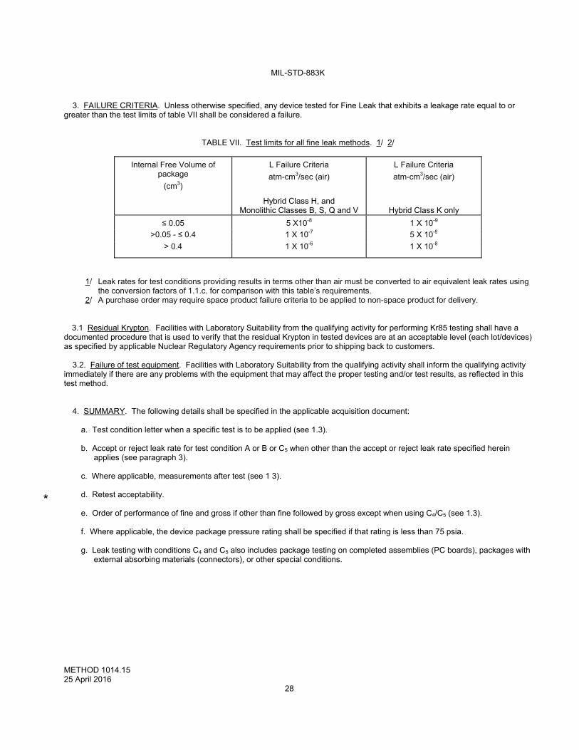
MIL-STD-883K
METHOD 1014.15 25 April 2016
28
3. FAILURE CRITERIA. Unless otherwise specified, any device tested for Fine Leak that exhibits a leakage rate equal to or
greater than the test limits of table VII shall be considered a failure.
TABLE VII. Test limits for all fine leak methods. 1/ 2/
Internal Free Volume of package
(cm3)
L Failure Criteria
atm-cm3/sec (air)
Hybrid Class H, and Monolithic Classes B, S, Q and V
L Failure Criteria
atm-cm3/sec (air)
Hybrid Class K only
≤ 0.05 5 X10⁻⁸ 1 X 10⁻⁹
>0.05 - ≤ 0.4 1 X 10⁻⁷ 5 X 10⁻⁹
> 0.4 1 X 10⁻⁶ 1 X 10⁻⁸
1/ Leak rates for test conditions providing results in terms other than air must be converted to air equivalent leak rates using the conversion factors of 1.1.c. for comparison with this table’s requirements.
2/ A purchase order may require space product failure criteria to be applied to non-space product for delivery.
3.1 Residual Krypton. Facilities with Laboratory Suitability from the qualifying activity for performing Kr85 testing shall have a documented procedure that is used to verify that the residual Krypton in tested devices are at an acceptable level (each lot/devices) as specified by applicable Nuclear Regulatory Agency requirements prior to shipping back to customers.
3.2. Failure of test equipment. Facilities with Laboratory Suitability from the qualifying activity shall inform the qualifying activity immediately if there are any problems with the equipment that may affect the proper testing and/or test results, as reflected in this test method.
4. SUMMARY. The following details shall be specified in the applicable acquisition document:
a. Test condition letter when a specific test is to be applied (see 1.3). b. Accept or reject leak rate for test condition A or B or C5 when other than the accept or reject leak rate specified herein
applies (see paragraph 3). c. Where applicable, measurements after test (see 1 3). d. Retest acceptability. e. Order of performance of fine and gross if other than fine followed by gross except when using C4/C5 (see 1.3). f. Where applicable, the device package pressure rating shall be specified if that rating is less than 75 psia. g. Leak testing with conditions C4 and C5 also includes package testing on completed assemblies (PC boards), packages with
external absorbing materials (connectors), or other special conditions.
*