Embed Size (px)
Citation preview
INCH-POUND MIL-DTL-32237B 11 July 2011
SUPERSEDING MIL-DTL-32237A 15 April 2011
DETAIL SPECIFICATION
BOOT, COMBAT, HOT WEATHER ARMY This specification is approved for use by all Departments and Agencies of the Department of Defense. 1. SCOPE 1.1 Scope. This specification covers the requirements for a Desert Sand-colored Hot Weather Combat Boot for use in both hot weather wet and dry environments. 1.2 Classification. This specification covers the following sizes and widths (see 6.2).
Size: 2 through 15 (whole and half sizes), 16 (whole size only)
Widths: Narrow (B) Wide (EE) Regular (D) X-Wide (EEEE) 2. APPLICABLE DOCUMENTS 2.1 General. The documents listed in this section are specified in sections 3, 4, or 5 of this specification. This section does not include documents cited in other sections of this specification or recommended for additional information or as examples. While every effort has been made to ensure the completeness of this list, document users are cautioned that they must meet all specified requirements of documents cited in sections 3, 4, or 5 of this specification, whether or not they are listed. Comments, suggestions, or questions on this document should be addressed to: Attn: DLA Troop Support Standardization Team, 700 Robbins Avenue, Philadelphia, PA 19111-5096. Since contact information can change, you may want to verify the currency of the address information using Acquisition Streamlining and Standardization Information System (ASSIST) online database https://assist.daps.dla.mil/. AMSC/NA FSC 8430
Downloaded from http://www.everyspec.com
MIL-DTL-32237B
2
2.2 Government documents. 2.2.1 Specifications. standards and handbooks. The following specifications, standards, and handbooks form a part of this document to the extent specified herein. Unless otherwise specified, the issues of these documents are those cited in the solicitation or contract (see 6.2).
COMMERCIAL ITEM DESCRIPTIONS
A-A-52071 - Tape, Textile, Cotton, General Purpose A-A-55093 - Laces, Nylon A-A-55296 - Cloth, Twill, Cotton, 10.0 Ounces (339g) A-A-59826 - Thread, Nylon
DEPARTMENT OF DEFENSE SPECIFICATIONS
MIL-C-41814 - Counter, Footwear MIL-DTL-32075 - Label: For Clothing, Equipage, and Tentage, (General Use) MIL-PRF-3122 - Leather, Cattlehide, for Footwear Uppers, Gusset, Chrome Tanned, Fatliquored MIL-PRF-5038 - Tape, Textile and Webbing, Textile, Reinforcing, Nylon MIL-W-17337 - Webbing, Textile, Woven Nylon (Copies of these documents are available online at https://assist.daps.dla.mil/quicksearch/ or from the Standardization Document Order Desk, 700 Robbins Avenue, Building 4D, Philadelphia, PA 19111-5094.)
2.2.2 Other Government documents, drawings and publications. The following other Government documents drawings and publications form a part of this document to the extent specified herein. Unless otherwise specified, the issues of these documents are those cited in the solicitation or contract.
DRAWINGS
DLA TROOP SUPPORT
2-1-1635 - Speed Lace Assembly (Copies of drawings are available from the DLA Troop Support, 700 Robbins Avenue, Philadelphia, PA 19111-5096, Attn: DSCP-CRFD-TDR.) FEDERAL TRADE COMMISSION Rules and Regulations Under the Textile Fiber Products Identification Act (Copies are available online at http://www.ftc.gov or from the Federal Trade Commission, 600 Pennsylvania Avenue, N.W., Washington, DC 20580-0001.)
Downloaded from http://www.everyspec.com
MIL-DTL-32237B
3
PURCHASE DESCRIPTIONS GL-PD-10-07 Cloth, Duck Textured Nylon (Copies of purchase descriptions, specifications, standards, drawings and publications required by contractors in connection with specification procurement functions should be obtained from the procuring activity or as directed by the Contracting Officer.) 2.3 Non-Government publications. The following documents form a part of this document to the extent specified herein. Unless otherwise specified, the issues of the documents are those cited in the solicitation or contract (see 6.2). AMERICAN ASSOCIATION OF TEXTILE CHEMISTS AND COLORISTS (AATCC)
AATCC – 118 - Oil Repellency, Hydrocarbon Resistance Test AATCC Evaluation Procedure 9, Visual Assessment of Color Difference of Textiles (Copies are available on line at http://www.aatcc.org or from the American Association of Textile Chemists and Colorists, P.O. Box 12215, Research Triangle Park, NC 27709-2215.)
AMERICAN SOCIETY FOR QUALITY
ANSI/ASQ Z1.4 - Sampling Procedures and Tables for Inspection of Attributes (Copies are available online at http://www.asq.org or from the American Society for Quality, 600 North Plankinton Avenue, Milwaukee, WI 53203.) ASTM INTERNATIONAL ASTM D 412 - Standard Test Method for Vulcanized Rubber and Thermoplastic
Elastomers – Tension ASTM D 471 - Standard Test method for Rubber Property-Effect of Liquids ASTM D 624 - Standard Test Method for Tear Strength of Conventional Vulcanized Rubber and Thermoplastic Elastomers ASTM D 792 - Standard Test Method for Density and Specific Gravity (relative Density) of Plastics by displacement ASTM D 1052 - Standard Test Method for Measuring Rubber Deterioration-Cut Growth
Using Ross Flexing Apparatus ASTM D 1630 - Standard Test Method for Rubber Property-Abrasion resistance
(Footwear Abrader) ASTM D 1777 - Standard Test Method for Thickness of Textile Materials ASTM D 2208 - Standard Test Method for Breaking Strength of Leather by the Grab Method ASTM D 2240 - Standard Test Method for Rubber Property-Durometer Hardness ASTM D 3273 - Standard Test Method for Resistance to Growth of Mold on the Surface
of Interior Coatings in an Environmental Chamber ASTM D 3574 - Standard Test Method for Flexible Cellular Materials-slab, Bonded, and
Downloaded from http://www.everyspec.com
MIL-DTL-32237B
4
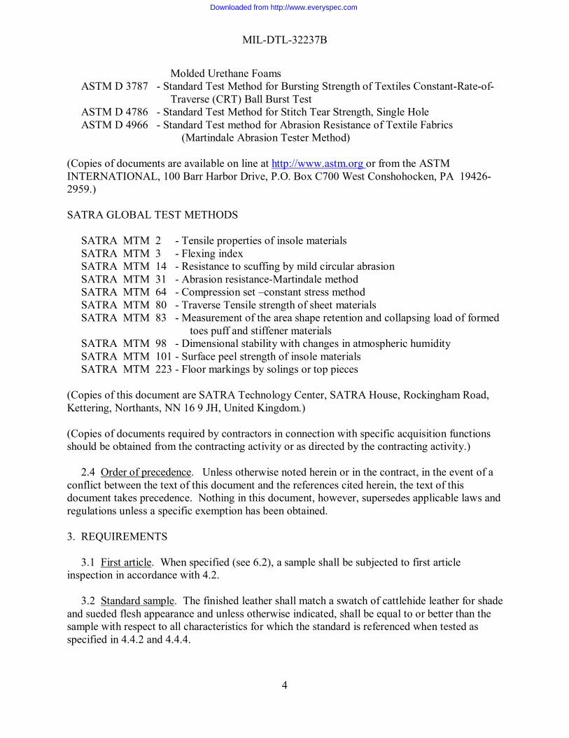
Molded Urethane Foams ASTM D 3787 - Standard Test Method for Bursting Strength of Textiles Constant-Rate-of- Traverse (CRT) Ball Burst Test ASTM D 4786 - Standard Test Method for Stitch Tear Strength, Single Hole ASTM D 4966 - Standard Test method for Abrasion Resistance of Textile Fabrics
(Martindale Abrasion Tester Method) (Copies of documents are available on line at http://www.astm.org or from the ASTM INTERNATIONAL, 100 Barr Harbor Drive, P.O. Box C700 West Conshohocken, PA 19426-2959.)
SATRA GLOBAL TEST METHODS SATRA MTM 2 - Tensile properties of insole materials SATRA MTM 3 - Flexing index SATRA MTM 14 - Resistance to scuffing by mild circular abrasion SATRA MTM 31 - Abrasion resistance-Martindale method SATRA MTM 64 - Compression set –constant stress method SATRA MTM 80 - Traverse Tensile strength of sheet materials SATRA MTM 83 - Measurement of the area shape retention and collapsing load of formed toes puff and stiffener materials SATRA MTM 98 - Dimensional stability with changes in atmospheric humidity SATRA MTM 101 - Surface peel strength of insole materials SATRA MTM 223 - Floor markings by solings or top pieces
(Copies of this document are SATRA Technology Center, SATRA House, Rockingham Road, Kettering, Northants, NN 16 9 JH, United Kingdom.) (Copies of documents required by contractors in connection with specific acquisition functions should be obtained from the contracting activity or as directed by the contracting activity.) 2.4 Order of precedence. Unless otherwise noted herein or in the contract, in the event of a conflict between the text of this document and the references cited herein, the text of this document takes precedence. Nothing in this document, however, supersedes applicable laws and regulations unless a specific exemption has been obtained.
3. REQUIREMENTS 3.1 First article. When specified (see 6.2), a sample shall be subjected to first article inspection in accordance with 4.2. 3.2 Standard sample. The finished leather shall match a swatch of cattlehide leather for shade and sueded flesh appearance and unless otherwise indicated, shall be equal to or better than the sample with respect to all characteristics for which the standard is referenced when tested as specified in 4.4.2 and 4.4.4.
Downloaded from http://www.everyspec.com
MIL-DTL-32237B
5
3.3 Recycled, recovered, or environmentally preferable materials. Recycled recovered or environmentally preferable materials should be used to the maximum extent possible provided that the material meets or exceeds the requirements of this document and promotes economically advantageous life cycle costs. 3.4 Materials. 3.4.1 Upper leather. The leather shall be flesh out drum dyed Desert Sand with color penetrating throughout the thickness of the hide. The chrome tannage shall not be visible. The leather for the vamps, inside counter pockets, outside counter pockets and eyelet stays shall conform to MIL-PRF-3122, Type I, Treatment A and B. The leather for the front edge eyelet stays shall conform to MIL-PRF-3122, Type II, Treatment A. The following exceptions to MIL- PRF-3122 shall be applicable for the upper leathers:
a. The flesh surface shall be suede to produce a fine uniform nap. b. The grain surface shall be lightly buffed to remove the surface of the grain only. c. The finish requirements for the leather shall not apply. d. The tear strength requirements for the front edge stays, inside counter
pockets and eyelet stays shall not apply. e. The thickness shall be as specified for the cut parts in Table IX. f. As an option, the eyelet stays may conform to MIL-PRF-3122, Type I, Treatment A
and Treatment B.
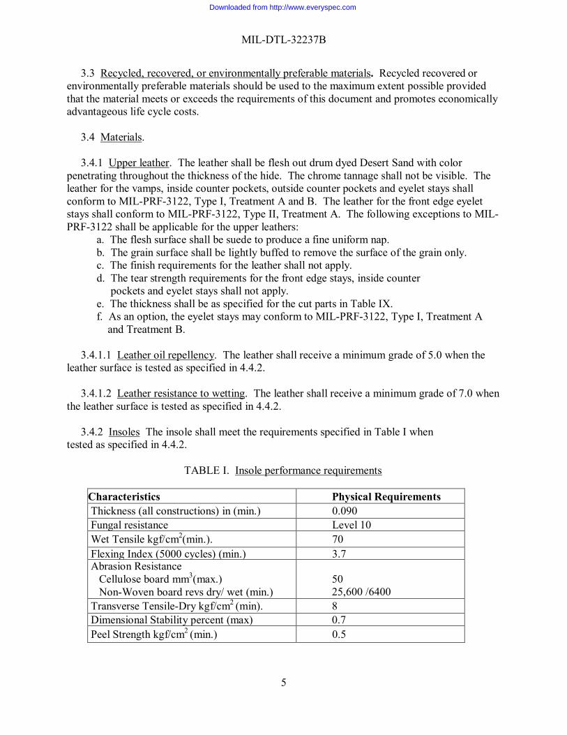
3.4.1.1 Leather oil repellency. The leather shall receive a minimum grade of 5.0 when the leather surface is tested as specified in 4.4.2. 3.4.1.2 Leather resistance to wetting. The leather shall receive a minimum grade of 7.0 when the leather surface is tested as specified in 4.4.2. 3.4.2 Insoles The insole shall meet the requirements specified in Table I when tested as specified in 4.4.2.
TABLE I. Insole performance requirements
Characteristics Physical Requirements Thickness (all constructions) in (min.) 0.090 Fungal resistance Level 10 Wet Tensile kgf/cm2(min.). 70 Flexing Index (5000 cycles) (min.) 3.7 Abrasion Resistance
Cellulose board mm3(max.) Non-Woven board revs dry/ wet (min.)
50 25,600 /6400
Transverse Tensile-Dry kgf/cm2 (min). 8 Dimensional Stability percent (max) 0.7 Peel Strength kgf/cm2 (min.) 0.5
Downloaded from http://www.everyspec.com
MIL-DTL-32237B
6
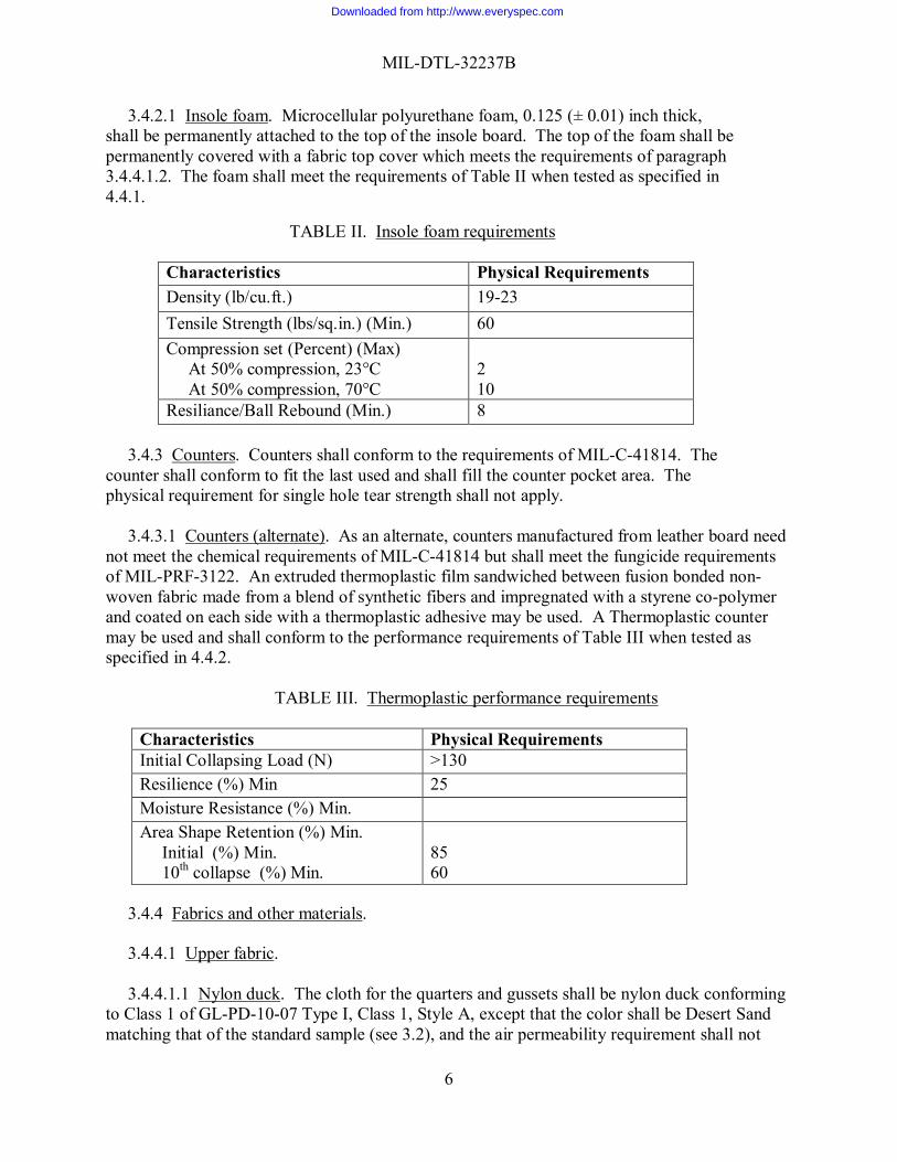
3.4.2.1 Insole foam. Microcellular polyurethane foam, 0.125 (± 0.01) inch thick, shall be permanently attached to the top of the insole board. The top of the foam shall be permanently covered with a fabric top cover which meets the requirements of paragraph 3.4.4.1.2. The foam shall meet the requirements of Table II when tested as specified in 4.4.1.
TABLE II. Insole foam requirements
Characteristics Physical Requirements Density (lb/cu.ft.) 19-23 Tensile Strength (lbs/sq.in.) (Min.) 60 Compression set (Percent) (Max) At 50% compression, 23°C At 50% compression, 70°C
2 10
Resiliance/Ball Rebound (Min.) 8 3.4.3 Counters. Counters shall conform to the requirements of MIL-C-41814. The counter shall conform to fit the last used and shall fill the counter pocket area. The physical requirement for single hole tear strength shall not apply.
3.4.3.1 Counters (alternate). As an alternate, counters manufactured from leather board need not meet the chemical requirements of MIL-C-41814 but shall meet the fungicide requirements of MIL-PRF-3122. An extruded thermoplastic film sandwiched between fusion bonded non-woven fabric made from a blend of synthetic fibers and impregnated with a styrene co-polymer and coated on each side with a thermoplastic adhesive may be used. A Thermoplastic counter may be used and shall conform to the performance requirements of Table III when tested as specified in 4.4.2.
TABLE III. Thermoplastic performance requirements
Characteristics Physical Requirements Initial Collapsing Load (N) >130 Resilience (%) Min 25 Moisture Resistance (%) Min. Area Shape Retention (%) Min. Initial (%) Min. 10th collapse (%) Min.
85 60
3.4.4 Fabrics and other materials. 3.4.4.1 Upper fabric. 3.4.4.1.1 Nylon duck. The cloth for the quarters and gussets shall be nylon duck conforming to Class 1 of GL-PD-10-07 Type I, Class 1, Style A, except that the color shall be Desert Sand matching that of the standard sample (see 3.2), and the air permeability requirement shall not
Downloaded from http://www.everyspec.com
MIL-DTL-32237B
7
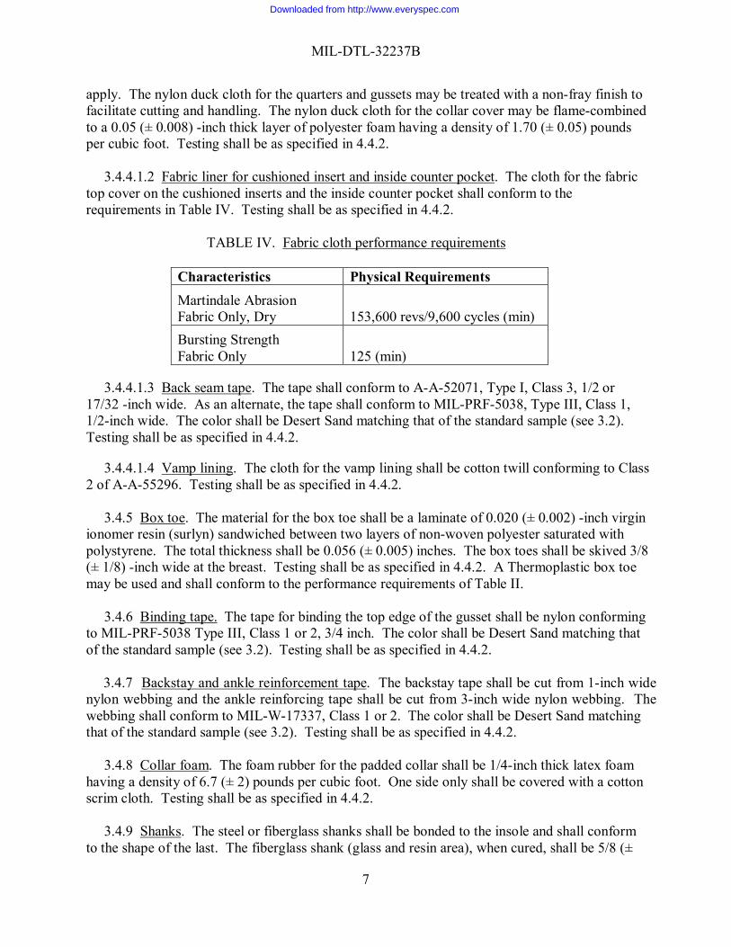
apply. The nylon duck cloth for the quarters and gussets may be treated with a non-fray finish to facilitate cutting and handling. The nylon duck cloth for the collar cover may be flame-combined to a 0.05 (± 0.008) -inch thick layer of polyester foam having a density of 1.70 (± 0.05) pounds per cubic foot. Testing shall be as specified in 4.4.2. 3.4.4.1.2 Fabric liner for cushioned insert and inside counter pocket. The cloth for the fabric top cover on the cushioned inserts and the inside counter pocket shall conform to the requirements in Table IV. Testing shall be as specified in 4.4.2.
TABLE IV. Fabric cloth performance requirements
Characteristics Physical Requirements Martindale Abrasion Fabric Only, Dry 153,600 revs/9,600 cycles (min) Bursting Strength Fabric Only 125 (min)
3.4.4.1.3 Back seam tape. The tape shall conform to A-A-52071, Type I, Class 3, 1/2 or 17/32 -inch wide. As an alternate, the tape shall conform to MIL-PRF-5038, Type III, Class 1, 1/2-inch wide. The color shall be Desert Sand matching that of the standard sample (see 3.2). Testing shall be as specified in 4.4.2. 3.4.4.1.4 Vamp lining. The cloth for the vamp lining shall be cotton twill conforming to Class 2 of A-A-55296. Testing shall be as specified in 4.4.2. 3.4.5 Box toe. The material for the box toe shall be a laminate of 0.020 (± 0.002) -inch virgin ionomer resin (surlyn) sandwiched between two layers of non-woven polyester saturated with polystyrene. The total thickness shall be 0.056 (± 0.005) inches. The box toes shall be skived 3/8 (± 1/8) -inch wide at the breast. Testing shall be as specified in 4.4.2. A Thermoplastic box toe may be used and shall conform to the performance requirements of Table II. 3.4.6 Binding tape. The tape for binding the top edge of the gusset shall be nylon conforming to MIL-PRF-5038 Type III, Class 1 or 2, 3/4 inch. The color shall be Desert Sand matching that of the standard sample (see 3.2). Testing shall be as specified in 4.4.2. 3.4.7 Backstay and ankle reinforcement tape. The backstay tape shall be cut from 1-inch wide nylon webbing and the ankle reinforcing tape shall be cut from 3-inch wide nylon webbing. The webbing shall conform to MIL-W-17337, Class 1 or 2. The color shall be Desert Sand matching that of the standard sample (see 3.2). Testing shall be as specified in 4.4.2. 3.4.8 Collar foam. The foam rubber for the padded collar shall be 1/4-inch thick latex foam having a density of 6.7 (± 2) pounds per cubic foot. One side only shall be covered with a cotton scrim cloth. Testing shall be as specified in 4.4.2. 3.4.9 Shanks. The steel or fiberglass shanks shall be bonded to the insole and shall conform to the shape of the last. The fiberglass shank (glass and resin area), when cured, shall be 5/8 (±
Downloaded from http://www.everyspec.com
MIL-DTL-32237B
8
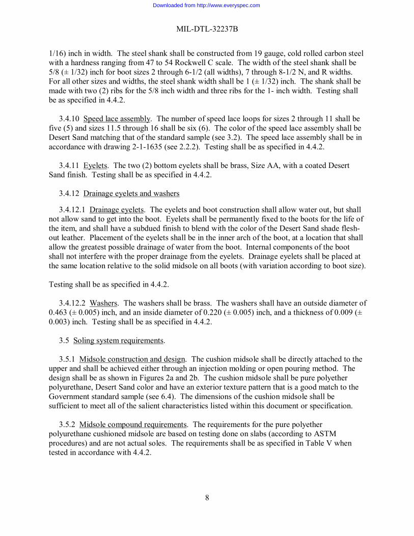
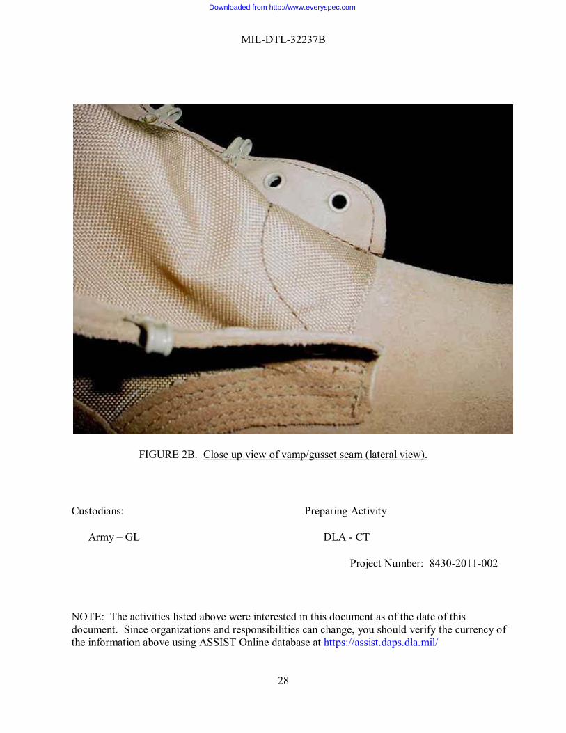
1/16) inch in width. The steel shank shall be constructed from 19 gauge, cold rolled carbon steel with a hardness ranging from 47 to 54 Rockwell C scale. The width of the steel shank shall be 5/8 (± 1/32) inch for boot sizes 2 through 6-1/2 (all widths), 7 through 8-1/2 N, and R widths. For all other sizes and widths, the steel shank width shall be 1 (± 1/32) inch. The shank shall be made with two (2) ribs for the 5/8 inch width and three ribs for the 1- inch width. Testing shall be as specified in 4.4.2. 3.4.10 Speed lace assembly. The number of speed lace loops for sizes 2 through 11 shall be five (5) and sizes 11.5 through 16 shall be six (6). The color of the speed lace assembly shall be Desert Sand matching that of the standard sample (see 3.2). The speed lace assembly shall be in accordance with drawing 2-1-1635 (see 2.2.2). Testing shall be as specified in 4.4.2. 3.4.11 Eyelets. The two (2) bottom eyelets shall be brass, Size AA, with a coated Desert Sand finish. Testing shall be as specified in 4.4.2. 3.4.12 Drainage eyelets and washers 3.4.12.1 Drainage eyelets. The eyelets and boot construction shall allow water out, but shall not allow sand to get into the boot. Eyelets shall be permanently fixed to the boots for the life of the item, and shall have a subdued finish to blend with the color of the Desert Sand shade flesh-out leather. Placement of the eyelets shall be in the inner arch of the boot, at a location that shall allow the greatest possible drainage of water from the boot. Internal components of the boot shall not interfere with the proper drainage from the eyelets. Drainage eyelets shall be placed at the same location relative to the solid midsole on all boots (with variation according to boot size). Testing shall be as specified in 4.4.2. 3.4.12.2 Washers. The washers shall be brass. The washers shall have an outside diameter of 0.463 (± 0.005) inch, and an inside diameter of 0.220 (± 0.005) inch, and a thickness of 0.009 (± 0.003) inch. Testing shall be as specified in 4.4.2. 3.5 Soling system requirements. 3.5.1 Midsole construction and design. The cushion midsole shall be directly attached to the upper and shall be achieved either through an injection molding or open pouring method. The design shall be as shown in Figures 2a and 2b. The cushion midsole shall be pure polyether polyurethane, Desert Sand color and have an exterior texture pattern that is a good match to the Government standard sample (see 6.4). The dimensions of the cushion midsole shall be sufficient to meet all of the salient characteristics listed within this document or specification. 3.5.2 Midsole compound requirements. The requirements for the pure polyether polyurethane cushioned midsole are based on testing done on slabs (according to ASTM procedures) and are not actual soles. The requirements shall be as specified in Table V when tested in accordance with 4.4.2.
Downloaded from http://www.everyspec.com
MIL-DTL-32237B
9
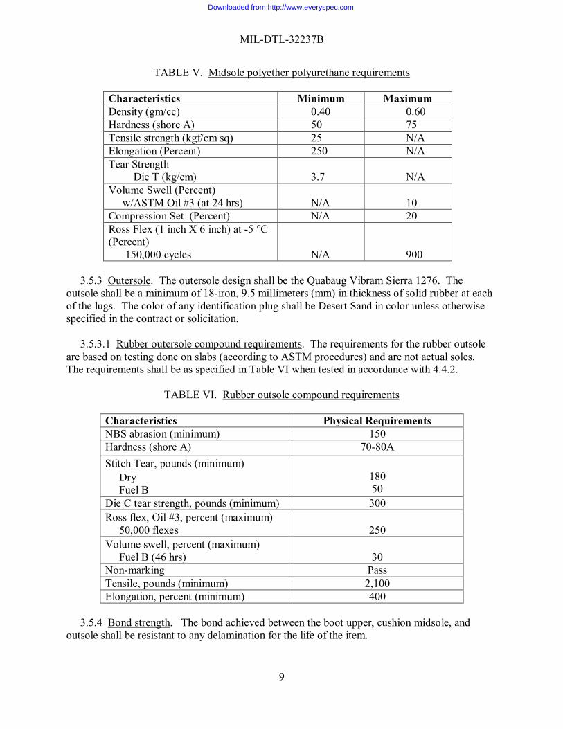
TABLE V. Midsole polyether polyurethane requirements
Characteristics Minimum Maximum Density (gm/cc) 0.40 0.60 Hardness (shore A) 50 75 Tensile strength (kgf/cm sq) 25 N/A Elongation (Percent) 250 N/A Tear Strength Die T (kg/cm)
3.7
N/A
Volume Swell (Percent) w/ASTM Oil #3 (at 24 hrs)
N/A
10
Compression Set (Percent) N/A 20 Ross Flex (1 inch X 6 inch) at -5 °C (Percent) 150,000 cycles
N/A
900
3.5.3 Outersole. The outersole design shall be the Quabaug Vibram Sierra 1276. The outsole shall be a minimum of 18-iron, 9.5 millimeters (mm) in thickness of solid rubber at each of the lugs. The color of any identification plug shall be Desert Sand in color unless otherwise specified in the contract or solicitation. 3.5.3.1 Rubber outersole compound requirements. The requirements for the rubber outsole are based on testing done on slabs (according to ASTM procedures) and are not actual soles. The requirements shall be as specified in Table VI when tested in accordance with 4.4.2.
TABLE VI. Rubber outsole compound requirements
Characteristics Physical Requirements NBS abrasion (minimum) 150 Hardness (shore A) 70-80A Stitch Tear, pounds (minimum) Dry Fuel B
180 50
Die C tear strength, pounds (minimum) 300 Ross flex, Oil #3, percent (maximum) 50,000 flexes
250
Volume swell, percent (maximum) Fuel B (46 hrs)
30
Non-marking Pass Tensile, pounds (minimum) 2,100 Elongation, percent (minimum) 400
3.5.4 Bond strength. The bond achieved between the boot upper, cushion midsole, and outsole shall be resistant to any delamination for the life of the item.
Downloaded from http://www.everyspec.com
MIL-DTL-32237B
10
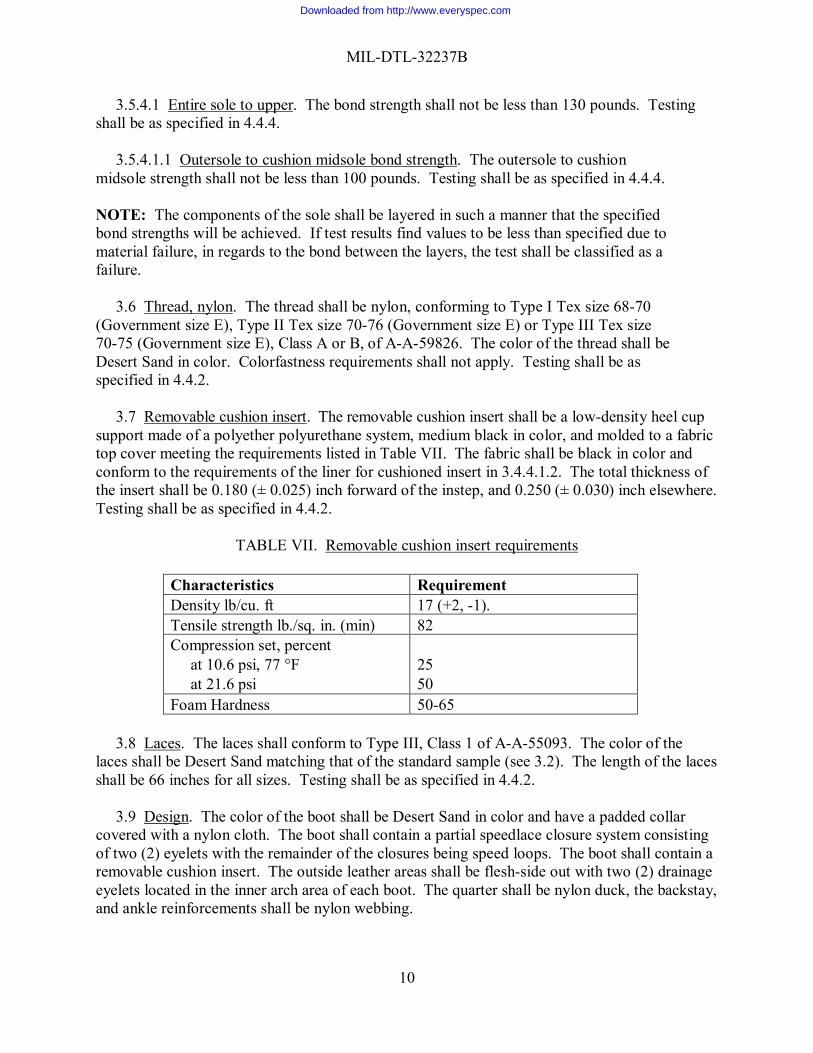
3.5.4.1 Entire sole to upper. The bond strength shall not be less than 130 pounds. Testing shall be as specified in 4.4.4. 3.5.4.1.1 Outersole to cushion midsole bond strength. The outersole to cushion midsole strength shall not be less than 100 pounds. Testing shall be as specified in 4.4.4. NOTE: The components of the sole shall be layered in such a manner that the specified bond strengths will be achieved. If test results find values to be less than specified due to material failure, in regards to the bond between the layers, the test shall be classified as a failure.
3.6 Thread, nylon. The thread shall be nylon, conforming to Type I Tex size 68-70 (Government size E), Type II Tex size 70-76 (Government size E) or Type III Tex size 70-75 (Government size E), Class A or B, of A-A-59826. The color of the thread shall be Desert Sand in color. Colorfastness requirements shall not apply. Testing shall be as specified in 4.4.2. 3.7 Removable cushion insert. The removable cushion insert shall be a low-density heel cup support made of a polyether polyurethane system, medium black in color, and molded to a fabric top cover meeting the requirements listed in Table VII. The fabric shall be black in color and conform to the requirements of the liner for cushioned insert in 3.4.4.1.2. The total thickness of the insert shall be 0.180 (± 0.025) inch forward of the instep, and 0.250 (± 0.030) inch elsewhere. Testing shall be as specified in 4.4.2.
TABLE VII. Removable cushion insert requirements
Characteristics Requirement Density lb/cu. ft 17 (+2, -1). Tensile strength lb./sq. in. (min) 82 Compression set, percent at 10.6 psi, 77 °F at 21.6 psi
25 50
Foam Hardness 50-65
3.8 Laces. The laces shall conform to Type III, Class 1 of A-A-55093. The color of the laces shall be Desert Sand matching that of the standard sample (see 3.2). The length of the laces shall be 66 inches for all sizes. Testing shall be as specified in 4.4.2. 3.9 Design. The color of the boot shall be Desert Sand in color and have a padded collar covered with a nylon cloth. The boot shall contain a partial speedlace closure system consisting of two (2) eyelets with the remainder of the closures being speed loops. The boot shall contain a removable cushion insert. The outside leather areas shall be flesh-side out with two (2) drainage eyelets located in the inner arch area of each boot. The quarter shall be nylon duck, the backstay, and ankle reinforcements shall be nylon webbing.
Downloaded from http://www.everyspec.com
MIL-DTL-32237B
11
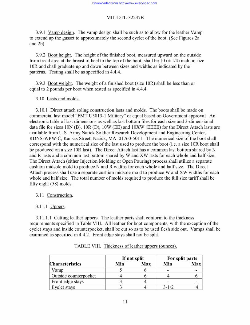
3.9.1 Vamp design. The vamp design shall be such as to allow for the leather Vamp to extend up the gusset to approximately the second eyelet of the boot. (See Figures 2a and 2b) 3.9.2 Boot height. The height of the finished boot, measured upward on the outside from tread area at the breast of heel to the top of the boot, shall be 10 (± 1/4) inch on size 10R and shall graduate up and down between sizes and widths as indicated by the patterns. Testing shall be as specified in 4.4.4. 3.9.3 Boot weight. The weight of a finished boot (size 10R) shall be less than or equal to 2 pounds per boot when tested as specified in 4.4.4. 3.10 Lasts and molds.
3.10.1 Direct attach soling construction lasts and molds. The boots shall be made on commercial last model “FMT U3813-1 Military” or equal based on Government approval. An electronic table of last dimensions as well as last bottom files for each size and 3-dimensional data file for sizes 10N (B), 10R (D), 10W (EE) and 10XW (EEEE) for the Direct Attach lasts are available from U.S. Army Natick Soldier Research Development and Engineering Center, RDNS-WPW-C, Kansas Street, Natick, MA 01760-5011. The numerical size of the boot shall correspond with the numerical size of the last used to produce the boot (i.e. a size 10R boot shall be produced on a size 10R last). The Direct Attach last has a common last bottom shared by N and R lasts and a common last bottom shared by W and XW lasts for each whole and half size. The Direct Attach (either Injection Molding or Open Pouring) process shall utilize a separate cushion midsole mold to produce N and R widths for each whole and half size. The Direct Attach process shall use a separate cushion midsole mold to produce W and XW widths for each whole and half size. The total number of molds required to produce the full size tariff shall be fifty eight (58) molds. 3.11 Construction. 3.11.1 Uppers. 3.11.1.1 Cutting leather uppers. The leather parts shall conform to the thickness requirements specified in Table VIII. All leather for boot components, with the exception of the eyelet stays and inside counterpocket, shall be cut so as to be used flesh side out. Vamps shall be examined as specified in 4.4.2. Front edge stays shall not be split.
TABLE VIII. Thickness of leather uppers (ounces).
Characteristics
If not split Min Max
For split parts Min Max
Vamp 5 6 - - Outside counterpocket 4 6 4 6 Front edge stays 3 4 - - Eyelet stays 3 4 3-1/2 4
Downloaded from http://www.everyspec.com
MIL-DTL-32237B
12
3.11.1.2 Cutting fabric upper parts. The quarters shall be cut in the bias direction on a 15 (+ 1) -degree bias from the warp direction. The collar cover shall be cut in the bias direction.
3.11.1.3 Marking, permanent identification. With the exception of PDMs (Product Demonstration Models), the gusset of each boot shall be marked on the inside, 1-inch from the top center of the gusset, with the correct American and Mondopoint sizes and widths, the contractor's identification symbol in block form, the month and year (expressed numerically) of the date of contract, the contract number (Example: 04-D-1234), and the company or brand name. The case number shall be marked. The marking shall conform to Type IV, Class 9 of MIL-DTL-32075. Fastness of the class 9 marking shall be as specified for the class 5 marking. Figures shall be Arabic and the letters shall be Gothic. The figures and letters shall be a minimum of 9/32 inch and a maximum of 3/8 inch in height. The stamping shall be expressed as shown in the following example; alternate formats may be used provided all the data elements are included and requirements are met:
10 W AB 6----06 3.11.2 Skiving. The vamp shall be skived at the throat and wings. The outside counterpocket shall be skived at the stitch edge and top. Additional upper leather skiving shall be permitted. 3.11.3 Finishing leather parts. The leather shall be flesh out drum dyed Desert Sand matching that of the standard sample (see 3.2) with the color penetrating throughout the thickness of the hide so that the chrome tannage shall not be visible. 3.11.4 Backstay seam strength. The seam strength of the backstay shall be not less than 250 pounds per inch. Testing shall be as specified in 4.5.3. 3.12 Assembly. 3.12.1 Insole. The insole shall be as specified in 3.4.2 of the appropriate thickness (see Table I). 3.12.2 Boot finishing. No top finish or treatment shall be applied. 3.12.3 Pairing, lacing, and instruction tag. The boots shall be paired. A lace shall be inserted through the top speed lace loop of the outside quarter of each boot, and the two (2) laces for each pair shall be tied firmly together. One (1) instruction tag (see 3.9) shall be attached to each pair of boots by inserting a lace through the hole in the instruction tag. 3.13 Instruction and hangtags. 3.13.1 Instruction tags. Instruction tags, to be tied to the finished boots, shall have a bar code located on the instruction tag of each pair of boots. The bar coding element shall be a 13 digit national stock number (NSN), and shall be a medium to high code density. The bar code shall be located so that it is completely visible on the item when it is folded and/or packaged as specified and so that it causes no damage to the item. The tags shall be printed on tag stock that is 5-1/4 by
Downloaded from http://www.everyspec.com
MIL-DTL-32237B
13
6-1/2 inches and folded in the middle to form four printed pages in book form that are 5-1/4 by 3-1/4 inches. A punch hole shall be made in the top near the folded edge for insertion of the lace. The Use and Care Information (see Attachment 1) must be included on the instruction tags. 3.13.2 Labels. The contractor shall attach a small circular tag with the words: “This Item Is Not Authorized For Flight or Combat Vehicle Use”. Component and boot feature hangtags may be attached to the boots. 3.14 Workmanship. The finished boots shall conform to the quality of product established by this document. The occurrence of defects shall not exceed the contractor's own quality assurance standards and the quality assurance standards defined by the technical data in the bid package. 4. VERIFICATION 4.1 Classification of inspections. The inspection requirements specified herein are classified
as follows: a. First article inspection (see paragraph 4.2). b. Conformance inspection (see paragraph 4. 3).
4.2 First article inspection. First article inspection when required (see 3.1) shall be examined for the defects specified in 4.4.3 and tested for the characteristics in 4.4.4.
4.3 Conformance inspection. Conformance inspection shall include the examinations of 4.4.1 through 4.4.1.3 and 4.4.3 and the testing in 4.4.2 and 4.4.4. Unless otherwise specified sampling for inspection shall be performed in accordance with ANSI/ASQ Z1.4.
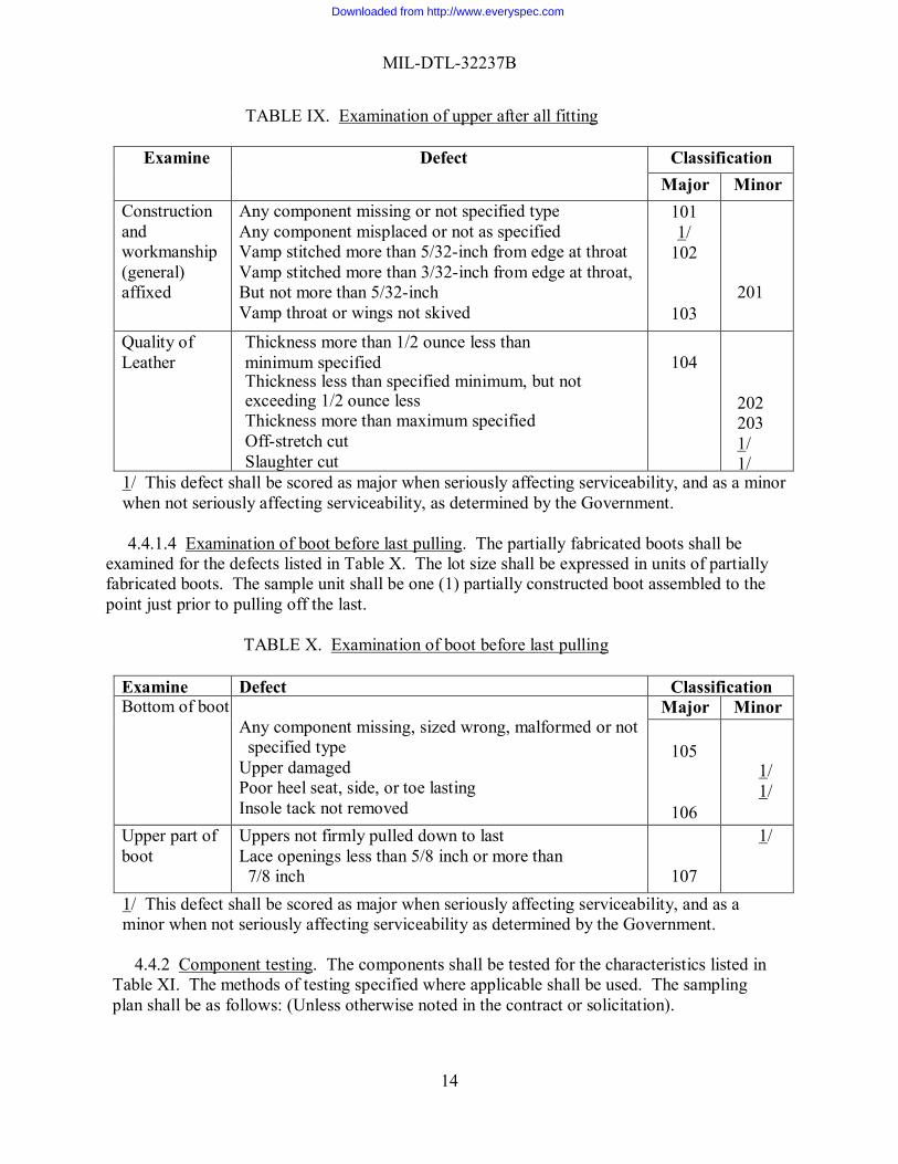
4.4 Component and material inspection. 4.4.1 In-process inspection. Inspection shall be made at any point or during any phase of manufacturing to determine whether the components are as specified or operations and/or assemblies are accomplished as specified. The Government reserves the right to exclude from consideration for acceptance any material or service for which in-process inspection has indicated nonconformance. 4.4.1.2 In-process examination. Examination shall be made for the component defects listed in 4.4.1.1 through 4.4.1.3 and classified as specified. The lot size shall be expressed in units of upper assemblies prepared for lasting. The sample unit shall be one (1) completely fabricated upper assembly prepared for lasting. 4.4.1.3 Examination uppers after all fitting. The upper assemblies shall be examined for the defects listed in Table IX. The lot size shall be expressed in units of upper assemblies prepared for lasting. The sample unit shall be one completely fabricated upper assembly prepared for lasting.
Downloaded from http://www.everyspec.com
MIL-DTL-32237B
14
TABLE IX. Examination of upper after all fitting
Examine Defect Classification Major Minor
Construction and workmanship (general) affixed
Any component missing or not specified type Any component misplaced or not as specified Vamp stitched more than 5/32-inch from edge at throat Vamp stitched more than 3/32-inch from edge at throat, But not more than 5/32-inch Vamp throat or wings not skived
101 1/
102
103
201
Quality of Leather
Thickness more than 1/2 ounce less than minimum specified Thickness less than specified minimum, but not exceeding 1/2 ounce less Thickness more than maximum specified Off-stretch cut Slaughter cut
104
202 203 1/ 1/
1/ This defect shall be scored as major when seriously affecting serviceability, and as a minor when not seriously affecting serviceability, as determined by the Government.
4.4.1.4 Examination of boot before last pulling. The partially fabricated boots shall be examined for the defects listed in Table X. The lot size shall be expressed in units of partially fabricated boots. The sample unit shall be one (1) partially constructed boot assembled to the point just prior to pulling off the last.
TABLE X. Examination of boot before last pulling
Examine Defect Classification Bottom of boot
Any component missing, sized wrong, malformed or not specified type
Upper damaged Poor heel seat, side, or toe lasting Insole tack not removed
Major Minor
105
106
1/ 1/
Upper part of boot
Uppers not firmly pulled down to last Lace openings less than 5/8 inch or more than 7/8 inch
107
1/
1/ This defect shall be scored as major when seriously affecting serviceability, and as a minor when not seriously affecting serviceability as determined by the Government.
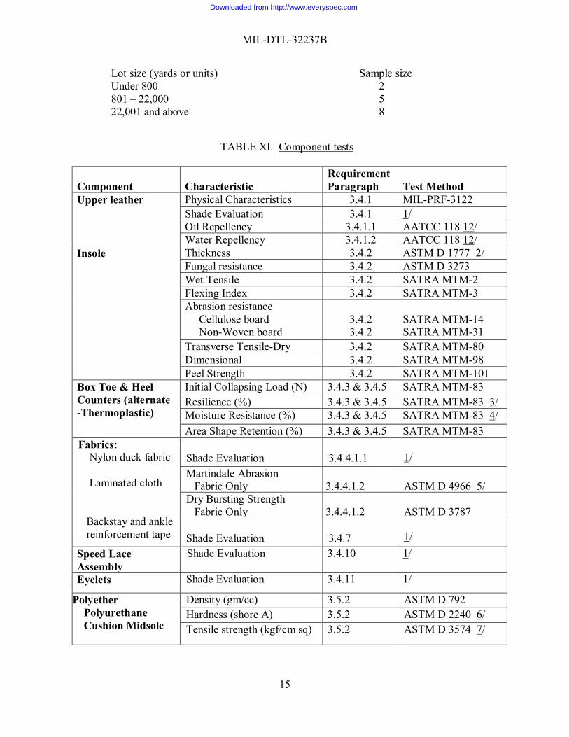
4.4.2 Component testing. The components shall be tested for the characteristics listed in Table XI. The methods of testing specified where applicable shall be used. The sampling plan shall be as follows: (Unless otherwise noted in the contract or solicitation).
Downloaded from http://www.everyspec.com
MIL-DTL-32237B
15
Lot size (yards or units) Sample size Under 800 2 801 – 22,000 5 22,001 and above 8
TABLE XI. Component tests Component
Characteristic
Requirement Paragraph
Test Method
Upper leather Physical Characteristics 3.4.1 MIL-PRF-3122 Shade Evaluation 3.4.1 1/ Oil Repellency 3.4.1.1 AATCC 118 12/
Water Repellency 3.4.1.2 AATCC 118 12/ Insole Thickness 3.4.2 ASTM D 1777 2/
Fungal resistance 3.4.2 ASTM D 3273 Wet Tensile 3.4.2 SATRA MTM-2 Flexing Index 3.4.2 SATRA MTM-3 Abrasion resistance Cellulose board Non-Woven board
3.4.2 3.4.2
SATRA MTM-14 SATRA MTM-31
Transverse Tensile-Dry
3.4.2
SATRA MTM-80 Dimensional
3.4.2
SATRA MTM-98 Peel Strength 3.4.2 SATRA MTM-101
Box Toe & Heel Counters (alternate -Thermoplastic)
Initial Collapsing Load (N) 3.4.3 & 3.4.5 SATRA MTM-83 Resilience (%) 3.4.3 & 3.4.5 SATRA MTM-83 3/ Moisture Resistance (%) 3.4.3 & 3.4.5 SATRA MTM-83 4/ Area Shape Retention (%) 3.4.3 & 3.4.5 SATRA MTM-83
Fabrics: Nylon duck fabric Laminated cloth Backstay and ankle reinforcement tape
Shade Evaluation
3.4.4.1.1
1/
Martindale Abrasion Fabric Only
3.4.4.1.2
ASTM D 4966 5/
Dry Bursting Strength Fabric Only
3.4.4.1.2
ASTM D 3787
Shade Evaluation 3.4.7
1/ Speed Lace
Assembly Shade Evaluation 3.4.10 1/
Eyelets Shade Evaluation 3.4.11 1/
Polyether Polyurethane Cushion Midsole
Density (gm/cc) 3.5.2 ASTM D 792 Hardness (shore A) 3.5.2 ASTM D 2240 6/ Tensile strength (kgf/cm sq) 3.5.2 ASTM D 3574 7/
Downloaded from http://www.everyspec.com
MIL-DTL-32237B
16
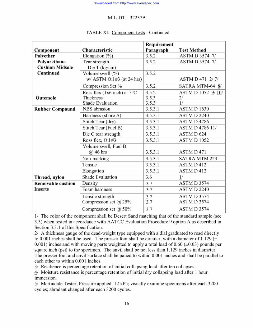
TABLE XI. Component tests - Continued Component
Characteristic
Requirement Paragraph
Test Method
Polyether Polyurethane Cushion Midsole Continued
Elongation (%) 3.5.2 ASTM D 3574 7/ Tear strength Die T (kg/cm)
3.5.2 ASTM D 3574 7/
Volume swell (%) w/ ASTM Oil #3 (at 24 hrs)
3.5.2 ASTM D 471 2/ 7/
Compression Set % 3.5.2 SATRA MTM-64 8/ Ross flex (1x6 inch) at 5°C 3.5.2 ASTM D 1052 9/ 10/
Outersole Thickness 3.5.3 2/ Shade Evaluation 3.5.3 1/
Rubber Compound NBS abrasion 3.5.3.1 ASTM D 1630 Hardness (shore A)
3.5.3.1 ASTM D 2240 Stitch Tear (dry)
3.5.3.1 ASTM D 4786
Stitch Tear (Fuel B)
3.5.3.1 ASTM D 4786 11/ Die C tear strength
3.5.3.1 ASTM D 624
Ross flex, Oil #3
3.5.3.1 ASTM D 1052 Volume swell, Fuel B
@ 46 hrs 3.5.3.1
ASTM D 471
Non-marking 3.5.3.1 SATRA MTM 223 Tensile
3.5.3.1 ASTM D 412
Elongation 3.5.3.1 ASTM D 412 Thread, nylon Shade Evaluation 3.6 1/ Removable cushion Inserts
Density 3.7 ASTM D 3574 Foam hardness 3.7 ASTM D 2240 Tensile strength 3.7 ASTM D 3574 Compression set @ 25% 3.7 ASTM D 3574 Compression set @ 50% 3.7 ASTM D 3574
1/ The color of the component shall be Desert Sand matching that of the standard sample (see 3.3) when tested in accordance with AATCC Evaluation Procedure 9 option A as described in Section 3.3.1 of this Specification. 2/ A thickness gauge of the dead-weight type equipped with a dial graduated to read directly to 0.001 inches shall be used. The presser foot shall be circular, with a diameter of 1.129 (+ 0.001) inches and with moving parts weighted to apply a total load of 0.60 (±0.03) pounds per square inch (psi) to the specimen. The anvil shall be not less than 1.129 inches in diameter. The presser foot and anvil surface shall be paned to within 0.001 inches and shall be parallel to each other to within 0.001 inches. 3/ Resilience is percentage retention of initial collapsing load after ten collapses. 4/ Moisture resistance is percentage retention of initial dry collapsing load after 1 hour immersion. 5/ Martindale Tester; Pressure applied: 12 kPa; visually examine specimens after each 3200 cycles; abradant changed after each 3200 cycles.
Downloaded from http://www.everyspec.com
MIL-DTL-32237B
17
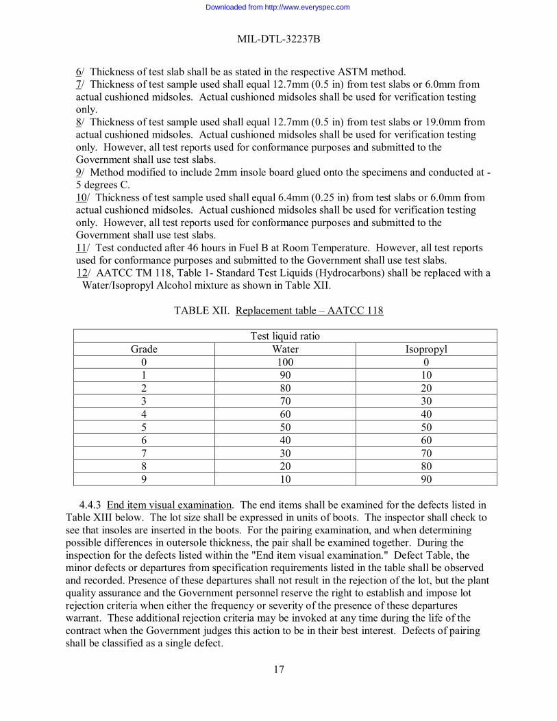
6/ Thickness of test slab shall be as stated in the respective ASTM method. 7/ Thickness of test sample used shall equal 12.7mm (0.5 in) from test slabs or 6.0mm from actual cushioned midsoles. Actual cushioned midsoles shall be used for verification testing only. 8/ Thickness of test sample used shall equal 12.7mm (0.5 in) from test slabs or 19.0mm from actual cushioned midsoles. Actual cushioned midsoles shall be used for verification testing only. However, all test reports used for conformance purposes and submitted to the Government shall use test slabs. 9/ Method modified to include 2mm insole board glued onto the specimens and conducted at -5 degrees C. 10/ Thickness of test sample used shall equal 6.4mm (0.25 in) from test slabs or 6.0mm from actual cushioned midsoles. Actual cushioned midsoles shall be used for verification testing only. However, all test reports used for conformance purposes and submitted to the Government shall use test slabs. 11/ Test conducted after 46 hours in Fuel B at Room Temperature. However, all test reports used for conformance purposes and submitted to the Government shall use test slabs.
12/ AATCC TM 118, Table 1- Standard Test Liquids (Hydrocarbons) shall be replaced with a Water/Isopropyl Alcohol mixture as shown in Table XII.
TABLE XII. Replacement table – AATCC 118
Test liquid ratio
Grade Water Isopropyl 0 100 0 1 90 10 2 80 20 3 70 30 4 60 40 5 50 50 6 40 60 7 30 70 8 20 80 9 10 90
4.4.3 End item visual examination. The end items shall be examined for the defects listed in Table XIII below. The lot size shall be expressed in units of boots. The inspector shall check to see that insoles are inserted in the boots. For the pairing examination, and when determining possible differences in outersole thickness, the pair shall be examined together. During the inspection for the defects listed within the "End item visual examination." Defect Table, the minor defects or departures from specification requirements listed in the table shall be observed and recorded. Presence of these departures shall not result in the rejection of the lot, but the plant quality assurance and the Government personnel reserve the right to establish and impose lot rejection criteria when either the frequency or severity of the presence of these departures warrant. These additional rejection criteria may be invoked at any time during the life of the contract when the Government judges this action to be in their best interest. Defects of pairing shall be classified as a single defect.
Downloaded from http://www.everyspec.com
MIL-DTL-32237B
18
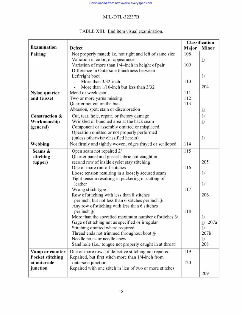
TABLE XIII. End item visual examination.
Examination Defect
Classification Major Minor
Pairing Not properly mated; i.e, not right and left of same size Variation in color, or appearance Variation of more than 1/4–inch in height of pair Difference in Outersole thinckness between Left/right boot - More than 3/32-inch - More than 1/16-inch but less than 3/32
108 109 110
1/ 1/ 204
Nylon quarter and Gusset
Mend or week spot Two or more yarns missing Quarter not cut on the bias Abrasion, spot, stain or discoloration
111 112 113
1/
Construction & Workmanship (general)
Cut, tear, hole, repair, or factory damage Wrinkled or bunched area at the back seam Component or assembly omitted or misplaced, Operation omitted or not properly performed (unless otherwise classified herein)
1/ 1/ 1/
Webbing Not firmly and tightly woven, edges frayed or scalloped 114 Seams & stitching (upper)
Open seam not repaired 2/ Quarter panel and gusset fabric not caught in second row of inside eyelet stay stitching One or more run-off stitches Loose tension resulting in a loosely secured seam Tight tension resulting in puckering or cutting of leather
Wrong stitch type Row of stitching with less than 8 stitches per inch, but not less than 6 stitches per inch 3/
Any row of stitching with less than 6 stitches per inch 3/
More than the specified maximum number of stitches 3/ Gage of stitching not as specified or irregular Stitching omitted where required Thread ends not trimmed throughout boot 4/ Needle holes or needle chew Sand hole (i.e., tongue not properly caught in at throat)
115 116 117 118
205 1/ 1/ 206 1/ 1/ 207a 1/ 207b 1/ 208
Vamp or counter Pocket stitching at outersole junction
One or more rows of defective stitching not repaired Repaired, but first stitch more than 1/4-inch from outersole junction Repaired with one stitch in lieu of two or more stitches
119 120
209
Downloaded from http://www.everyspec.com
MIL-DTL-32237B
19
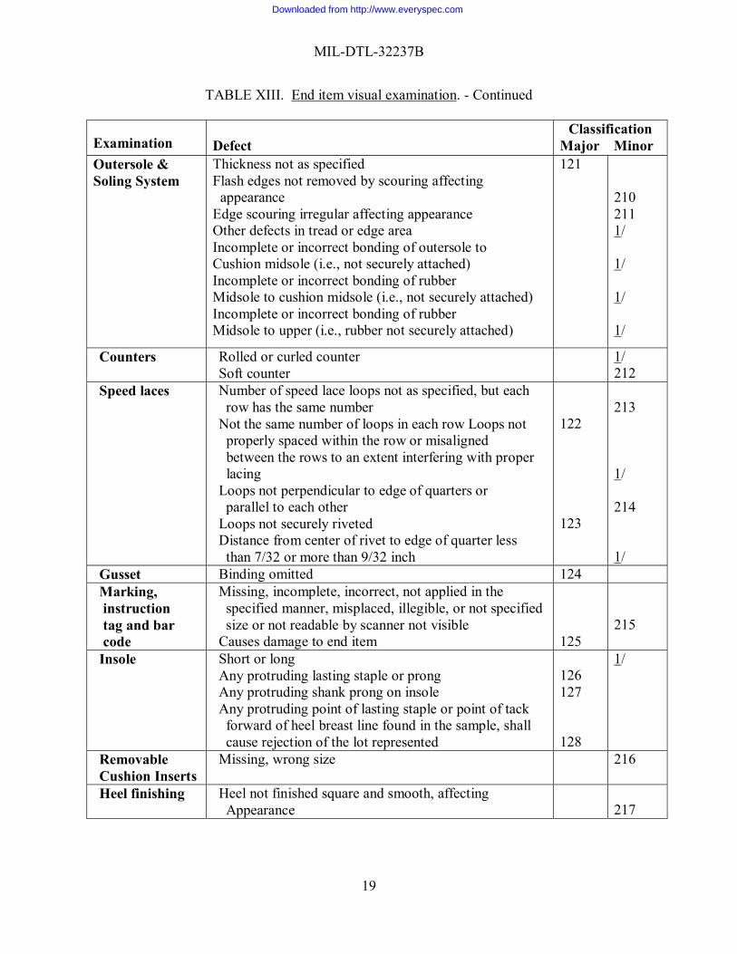
TABLE XIII. End item visual examination. - Continued
Examination Defect
Classification Major Minor
Outersole & Soling System
Thickness not as specified Flash edges not removed by scouring affecting appearance Edge scouring irregular affecting appearance Other defects in tread or edge area Incomplete or incorrect bonding of outersole to Cushion midsole (i.e., not securely attached) Incomplete or incorrect bonding of rubber Midsole to cushion midsole (i.e., not securely attached) Incomplete or incorrect bonding of rubber Midsole to upper (i.e., rubber not securely attached)
121 210 211 1/ 1/ 1/ 1/
Counters Rolled or curled counter Soft counter
1/ 212
Speed laces Number of speed lace loops not as specified, but each row has the same number
Not the same number of loops in each row Loops not properly spaced within the row or misaligned between the rows to an extent interfering with proper lacing Loops not perpendicular to edge of quarters or parallel to each other
Loops not securely riveted Distance from center of rivet to edge of quarter less than 7/32 or more than 9/32 inch
122 123
213 1/ 214 1/
Gusset Binding omitted 124 Marking, instruction tag and bar code
Missing, incomplete, incorrect, not applied in the specified manner, misplaced, illegible, or not specified size or not readable by scanner not visible
Causes damage to end item
125
215
Insole Short or long Any protruding lasting staple or prong Any protruding shank prong on insole Any protruding point of lasting staple or point of tack forward of heel breast line found in the sample, shall cause rejection of the lot represented
126 127 128
1/
Removable Cushion Inserts
Missing, wrong size 216
Heel finishing Heel not finished square and smooth, affecting Appearance
217
Downloaded from http://www.everyspec.com
MIL-DTL-32237B
20
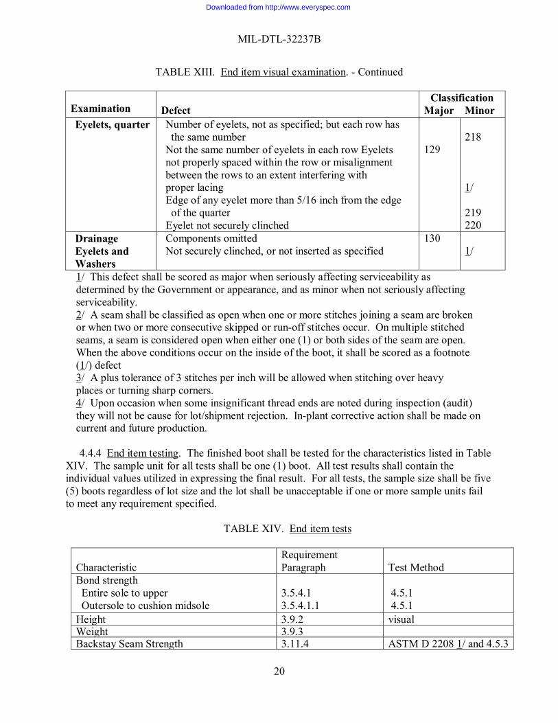
TABLE XIII. End item visual examination. - Continued
Examination Defect
Classification Major Minor
Eyelets, quarter Number of eyelets, not as specified; but each row has the same number
Not the same number of eyelets in each row Eyelets not properly spaced within the row or misalignment between the rows to an extent interfering with proper lacing Edge of any eyelet more than 5/16 inch from the edge of the quarter
Eyelet not securely clinched
129
218 1/ 219 220
Drainage Eyelets and Washers
Components omitted Not securely clinched, or not inserted as specified
130 1/
1/ This defect shall be scored as major when seriously affecting serviceability as determined by the Government or appearance, and as minor when not seriously affecting serviceability. 2/ A seam shall be classified as open when one or more stitches joining a seam are broken or when two or more consecutive skipped or run-off stitches occur. On multiple stitched seams, a seam is considered open when either one (1) or both sides of the seam are open. When the above conditions occur on the inside of the boot, it shall be scored as a footnote (1/) defect 3/ A plus tolerance of 3 stitches per inch will be allowed when stitching over heavy places or turning sharp corners. 4/ Upon occasion when some insignificant thread ends are noted during inspection (audit) they will not be cause for lot/shipment rejection. In-plant corrective action shall be made on current and future production.
4.4.4 End item testing. The finished boot shall be tested for the characteristics listed in Table XIV. The sample unit for all tests shall be one (1) boot. All test results shall contain the individual values utilized in expressing the final result. For all tests, the sample size shall be five (5) boots regardless of lot size and the lot shall be unacceptable if one or more sample units fail to meet any requirement specified.
TABLE XIV. End item tests
Characteristic
Requirement Paragraph
Test Method
Bond strength Entire sole to upper Outersole to cushion midsole
3.5.4.1 3.5.4.1.1
4.5.1 4.5.1
Height 3.9.2 visual Weight 3.9.3 Backstay Seam Strength 3.11.4 ASTM D 2208 1/ and 4.5.3
Downloaded from http://www.everyspec.com
MIL-DTL-32237B
21
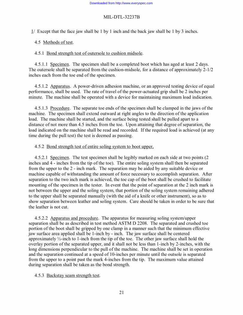
1/ Except that the face jaw shall be 1 by 1 inch and the back jaw shall be 1 by 3 inches. 4.5 Methods of test.
4.5.1 Bond strength test of outersole to cushion midsole. 4.5.1.1 Specimen. The specimen shall be a completed boot which has aged at least 2 days. The outersole shall be separated from the cushion-midsole, for a distance of approximately 2-1/2 inches each from the toe end of the specimen. 4.5.1.2 Apparatus. A power-driven adhesion machine, or an approved testing device of equal performance, shall be used. The rate of travel of the power-actuated grip shall be 2 inches per minute. The machine shall be operated with a device for maintaining maximum load indication. 4.5.1.3 Procedure. The separate toe ends of the specimen shall be clamped in the jaws of the machine. The specimen shall extend outward at right angles to the direction of the application load. The machine shall be started, and the surface being tested shall be pulled apart to a distance of not more than 4.5 inches from the toe. Upon attaining that degree of separation, the load indicated on the machine shall be read and recorded. If the required load is achieved (at any time during the pull test) the test is deemed as passing. 4.5.2 Bond strength test of entire soling system to boot upper, 4.5.2.1 Specimen. The test specimen shall be legibly marked on each side at two points (2 inches and 4 - inches from the tip of the toe). The entire soling system shall then be separated from the upper to the 2 - inch mark. The separation may be aided by any suitable device or machine capable of withstanding the amount of force necessary to accomplish separation. After separation to the two inch mark is achieved, the toe cap of the boot shall be crushed to facilitate mounting of the specimen in the tester. In event that the point of separation at the 2 inch mark is not between the upper and the soling system, that portion of the soling system remaining adhered to the upper shall be separated manually (with the aid of a knife or other instrument), so as to show separation between leather and soling system. Care should be taken in order to be sure that the leather is not cut. 4.5.2.2 Apparatus and procedure. The apparatus for measuring soling system/upper separation shall be as described in test method ASTM D 2208. The separated and crushed toe portion of the boot shall be gripped by one clamp in a manner such that the minimum effective jaw surface area applied shall be 1-inch by - inch. The jaw surface shall be centered approximately ½-inch to 1-inch from the tip of the toe. The other jaw surface shall hold the overlay portion of the separated upper, and it shall not be less than 1-inch by 2-inches, with the long dimensions perpendicular to the pull of the machine. The machine shall be set in operation and the separation continued at a speed of 10-inches per minute until the outsole is separated from the upper to a point past the mark 4-inches from the tip. The maximum value attained during separation shall be taken as the bond strength. 4.5.3 Backstay seam strength test.
Downloaded from http://www.everyspec.com
MIL-DTL-32237B
22
4.5.3.1 Specimen. The same boot used for the bond strength test may be used for this test. The test specimen shall be a single finished boot of any size prepared as follows: The fabric quarters shall be cut from the leather upper and edge stay and cut down the specimen to the seam, 1-1/2 to 2 inches above the bottom of the backseam. 4.5.3.2 Procedure. The apparatus for measuring backstay seam strength shall be as described in ASTM D 2208, except that the face jaw shall be 1 by 1-inch and the back jaw shall be 1 by 3 inches. Insert the specimen marked as described in Section 4.5.3.1 in the clamps so that the seam is centered between the jaws with the line in the center of the jaw faces and set the machine in operation. The maximum value attained during separation shall be taken as the backstay seam strength. 4.6 Visual shade matching (All components). The color and appearance of the components shall match the standard shade and appearance in 3.2 when viewed using AATCC Evaluation Procedure 9, Option A, with sources simulating artificial daylight D75 illuminant with a color temperature of 7500(+ 200)°K, illumination of 100 (+ 20) foot candles and shall be a good match to the standard sample under incandescent lamplight at 2856 (+ 200)°K. 5. PACKAGING. 5.1 Packaging. For acquisition purposes, the packaging requirements shall be as specified in the contract or order (see 6.2). When actual packaging of material is to be performed by DoD or in-house contractor personnel, these personnel need to contact the responsible packaging activity to ascertain requisite packaging requirements. Packaging requirements are maintained by the Inventory Control Point’s packaging activities within the Military Department or Defense Agency, or within the military service’s system commands. Packaging data retrieval is available from the managing Military Department’s or Defense Agency’s automated packaging files, CD-ROM products, or by contacting the responsible packaging activity. 6. NOTES 6.1 Intended use. The boots are intended for wear by military personnel of the Department of Defense in Hot Weather Wet Environments, Hot Weather Dry Environments, Garrison Environment and during combat. As the combat environment is more severe than that seen during commercial wear and use, it is expected that the items procured by the US Government will be superior to those found commercially. Any item not meeting the performance(s) specified herein, or which does not meet commercial standards for retail production and purchasing will not be accepted by the US Government for use by its Military personnel. 6.2 Acquisition requirements. Acquisition documents must specify the following:
a. Title, number and date of this specification. b. Sizes and widths required (see 1.2). c. The specific issue of individual document referenced (see 2.2). d. When first article is required, (see 3.1 and 4.2). e. Inclusion of specific instructions regarding arrangement for examinations, quantity, testing and approval (see 4.3).
Downloaded from http://www.everyspec.com
MIL-DTL-32237B
23
f. Packaging requirements (see 5.1) 6.3 First article. When a first article is required, it will be inspected and approved under the appropriate provisions of Federal Acquisition Regulation (FAR) 52.209-4. The first article should be a pre-production sample. The contracting officer should specify the appropriate type of first article and the number of units to be furnished. The contracting officer should also include specific instructions in acquisition documents regarding arrangements for selection, inspection, and approval of the first article (see 3.1 and 4.2). 6.4 Standard sample. For access to information such as patterns, drawings, standard shade samples go to DLA Troop Support website for their Specification/Pattern/Drawing request form at http://www.dscp.dla.mil/portal/sreqform.aspx. Complete the request form and then submit. For access to samples address the contracting activity issuing the invitation for bids or request for proposal.
6.5 Title. This document (MIL-DTL-32237) is for the Army, Combat, Hot Weather boot, and supersedes CR/PD 06-10, dated 19 June 2006. 6.6. Subject term (key word) listing. Desert Footwear Inserts Jungle Leather Outsoles 6.7 Changes from previous issue. The margins of this specification are marked with vertical lines to indicate where changes from the previous issue were made. This was done as a convenience only and the Government assumes no liability whatsoever for any inaccuracies in these notations. Bidders and contractors are cautioned to evaluate the requirements of this document based on the entire content irrespective of the marginal notations and relationship to the last previous issue.
Downloaded from http://www.everyspec.com
MIL-DTL-32237B
24
ATTACHMENT 1. Use and Care Instruction Tag
Use and Care Instructions
Army Combat Boot (Hot Weather)
1. Wear with: 1 pair of cushioned sole socks depending on safety/uniform requirements; 1 pair of insole inserts if desired.
2. Sizes. These boots are supplied in whole and half sizes 2 through 15 and 16 whole size, widths N (B), R (D), W (EE), and XW (EEEE). In some instances, it may be necessary to select a slightly larger size than normally worn in order to allow for normal swelling of the feet and the use of inserts or cushioned socks.
3. Pull on boot seating heel firmly into place, then lace. Boots should fit snugly but not tightly. There should be at least a 3/4-inch minimum additional length at toe.
4. Trousers should be bloused over the outside and below the comfort collar of the boot.
5. Break-in: DO NOT soak boots in water or bake in an oven to break-in. Boots should be
worn-in gradually at first with ever-increasing walking or marching distances while remaining comfortable. If blistering occurs, check to make sure that boots are fitted properly and that you are wearing recommended socks.
6. Your Combat Boots are designed for maximum performance in a field environment. Do
not apply polish to your Combat Boots.
7. Your Combat Boots are designed to be easy to care for. The nylon quarter side panels of your boots are as strong as leather and will last if cared for properly. To clean your Combat Boots, brush with stiff nylon bristle brush to clean and then use warm water. Do not use soap to clean your boots. If additional, more stringent cleaning is necessary, only water-soluble cleaning products should be used as oil- or alcohol-based cleaning products may damage your boots.
8. Your Combat Boots come with a replaceable rubber outsole. Do not wear sole past
rubber outsole into the softer midsole material or permanent damage to your boots will occur. The midsole is the soft cushioned material between the rubber lug outsole and the boot upper.
9. (Must include information on how/where the boots can get resoled or who to contact to
receive information on resoling.)
Downloaded from http://www.everyspec.com
MIL-DTL-32237B
25
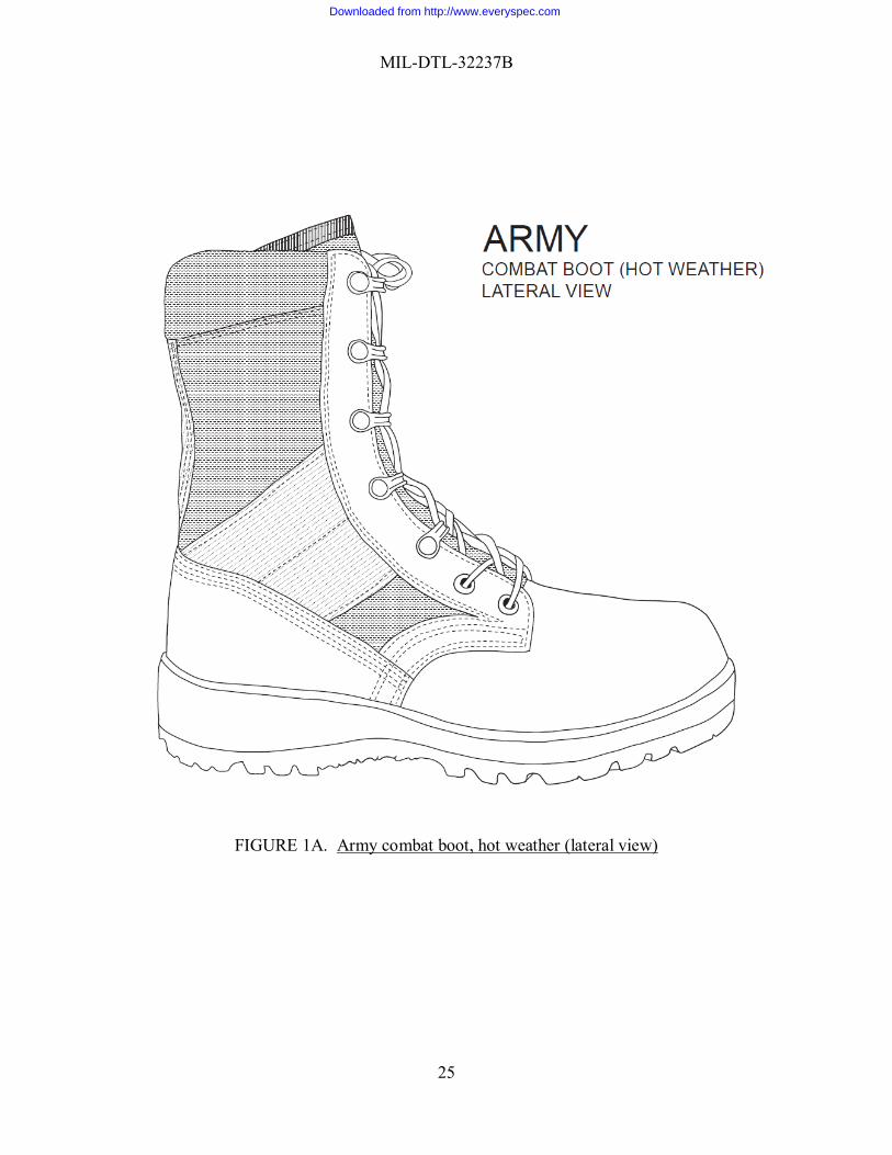
FIGURE 1A. Army combat boot, hot weather (lateral view)
Downloaded from http://www.everyspec.com
MIL-DTL-32237B
26
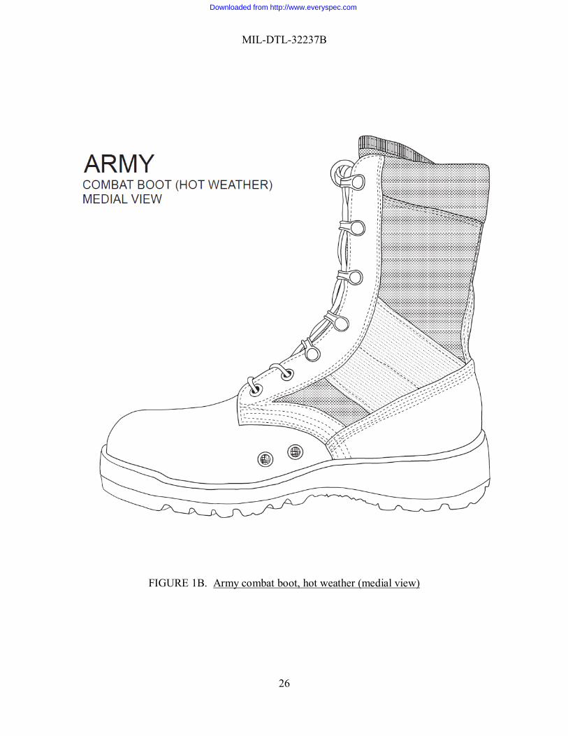
FIGURE 1B. Army combat boot, hot weather (medial view)
Downloaded from http://www.everyspec.com
MIL-DTL-32237B
27
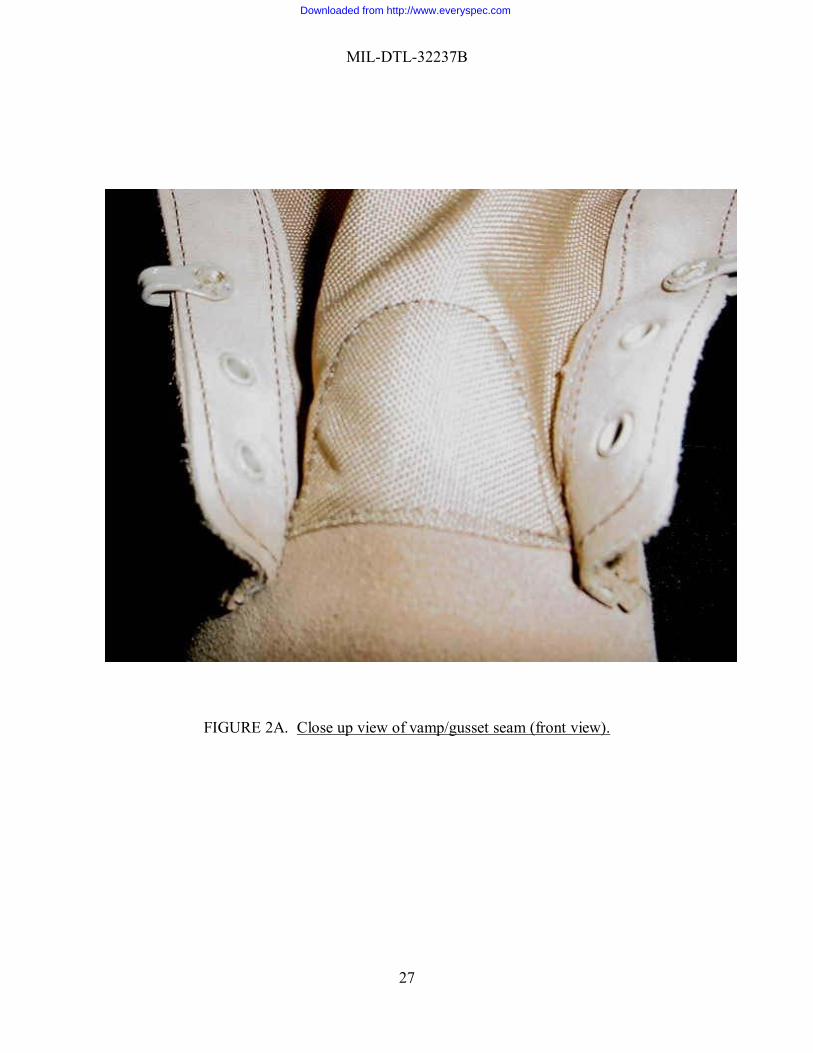
FIGURE 2A. Close up view of vamp/gusset seam (front view).
Downloaded from http://www.everyspec.com
MIL-DTL-32237B
28
FIGURE 2B. Close up view of vamp/gusset seam (lateral view). Custodians: Preparing Activity
Army – GL DLA - CT
Project Number: 8430-2011-002 NOTE: The activities listed above were interested in this document as of the date of this document. Since organizations and responsibilities can change, you should verify the currency of the information above using ASSIST Online database at https://assist.daps.dla.mil/
Downloaded from http://www.everyspec.com


![[NOT MEASUREMENT SENSITIVE] SUPERSEDING MIL-P-197Heveryspec.com/MIL-SPECS/MIL-SPECS-MIL-DTL/download.php?spec=… · [not measurement sensitive] mil-dtl-197j 9 july 2000 superseding](https://img.pdfslide.us/doc/110x75/5b80c51f7f8b9af7088e17c6/not-measurement-sensitive-superseding-mil-p-not-measurement-sensitive-mil-dtl-197j.jpg)