Embed Size (px)
Citation preview
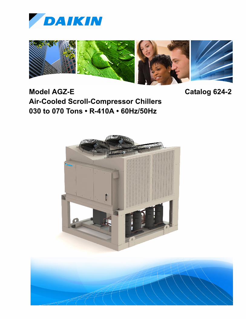
Model AGZ-E Catalog 624-2Air-Cooled Scroll-Compressor Chillers030 to 070 Tons • R-410A • 60Hz/50Hz
Contents
Introduction . . . . . . . . . . . . . . . . . . . . . . . . . . . . . . . 3Features and Benefits . . . . . . . . . . . . . . . . . . . . . . . 4Application Considerations . . . . . . . . . . . . . . . . . . .8Sound Data . . . . . . . . . . . . . . . . . . . . . . . . . . . . . . .14Selection Procedure . . . . . . . . . . . . . . . . . . . . . . . 18Performance Data . . . . . . . . . . . . . . . . . . . . . . . . . .19Part Load Performance Data (60 Hz) . . . . . . . . . .22Part Load Performance Data (50 Hz) . . . . . . . . . .23Pressure Drop Data . . . . . . . . . . . . . . . . . . . . . . . .24
Physical Data - Packaged Units . . . . . . . . . . . . . . 25Dimensions - Packaged . . . . . . . . . . . . . . . . . . . . . 28Lifting and Mounting Weights . . . . . . . . . . . . . . . 30Electrical Data . . . . . . . . . . . . . . . . . . . . . . . . . . . . 33Field Wiring Diagram . . . . . . . . . . . . . . . . . . . . . . 34Electrical Data . . . . . . . . . . . . . . . . . . . . . . . . . . . . 36Options and Accessories . . . . . . . . . . . . . . . . . . . 38Engineering Guide Specification . . . . . . . . . . . . . 40
Hazard Identification
NOTE: Cover photo shows unit with coil grilles.
DANGER
Dangers indicate a hazardous situation which will result in death or serious injury if not avoided.
WARNING
Warnings indicate potentially hazardous situations, which can result in property damage, severe personal injury, or death if not avoided.
CAUTION
Cautions indicate potentially hazardous situations, which can result in personal injury or equipment damage if not avoided.
Modbus
©2014 Daikin Applied. Illustrations and data cover the Daikin Applied product at the time of publication and we reserve the right to make changes in design and construction at anytime without notice.
CAT 624-2 3
IntroductionIntroduction
The AGZ family of air-cooled scroll chillers continues the Daikin Applied legacy of high quality, high efficiency, latest technology and quiet operation. These features make the AGZ family the best overall value in air-cooled packaged chillers available today. The AGZ-E series offers a wide selection of units from 30 to 70 tons with dual refrigerant circuits available as packaged units, with remote evaporators or with an optional pump package.
Efficient Operation
The AGZ units utilize environmentally acceptable R-410A refrigerant and meet the performance requirements of ASHRAE Standard 90.1 for efficiency. Excellent part-load performance is achieved with four or six scroll compressors. High overall efficiency = lower annual energy costs.
RapidRestore® and Fast Loading Technology
When power has been interrupted, the AGZ-E has the capability to restore cooling quicly making it ideal for mission critical buildings, data centers, healthcare facilities, and manufacturing processes. After a power loss duration of up to 180 seconds, the time for an AGZ-E chiller restart is less than 125 seconds with the chiller reaching full load within 220 seconds from power restoration.
Compact Size
Compact models with a small footprint continues to be a primary design feature. The coil design and canted fan deck
allow close spacing to walls and other units. These attributes lower installation cost and are excellent for replacement jobs.
Application Flexibility
AGZ-E units are available as packaged chillers or with remote evaporators. Information on remote evaporator models and factory-installed pump packages can be found in a separate installation manual available on www.DaikinApplied.com.
Quiet Operation
The AGZ units live up to the Daikin Applied reputation for low operating sound levels and make these chillers "neighborhood friendly.” Full load sound pressure levels as low as 60dB without insulation.
LEED® Points
Developed by the U.S. Green Building Council (USGBC) in 1998, Leadership in Energy and Environmental Design (LEED®) is an internationally recognized certification program and intends to provide building owners and operators a consistent structure for identifying and implementing practical and measurable green building design, construction, operations and maintenance solutions.
For building owners who want to pursue LEED Green Building Certification, the AGZ-E series of air-cooled chillers does qualify for the Energy and Atmosphere Credit 4, Enhanced Refrigerant Management worth 2 points.
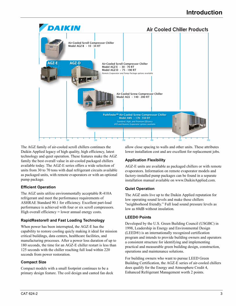
Air Cooled Chiller Products
1000 200 300 400 500 600
Pathfinder™ Air-Cooled Screw Compressor ChillerModel AWS • 170 - 550 RT
Standard, High, and Premium EfficencyVFD and Remote Evaporator options available
Air-Cooled Screw Compressor ChillerModel AGS • 140 - 200 RT
Air-Cooled Scroll Compressor ChillerModel AGZ-B • 10 - 34 RT
Pathfinder™
AM
Air-Cooled Scroll Compressor ChillerModel AGZ-E • 30 - 70 RTModel AGZ-D • 75 - 190 RTRemote Evaporator and Pump Package options available
AGZ-D
AM
AGZ-E
4 CAT 624-2
Features and Benefits
Chiller Nomenclature
Features and Benefits
Unit Design Features
Daikin AGZ air-cooled chillers are a product of our commitment to offer quiet, reliable, energy efficient equipment, incorporating high quality compressors, and innovative packaging.
Construction
AGZ chillers are factory-assembled and mounted on a heavy-gauge steel base. The base rails, supports and cabinetry are powder-coat painted for long life. The base distributes the unit weight for roof loading. Their small footprint allows smaller mounting pads or support structures and is a plus for retrofit or replacement applications.
Compressors
Reliable hermetic scroll compressors with cast iron scrolls and three Teflon® impregnated bearings are used on the AGZ-E chillers to promote longevity.
Each model has four steps of capacity modulation. One to four compressors can run, depending on the load of the system, resulting in excellent part-load efficiency and reduced annual operating costs.
Features include motor temperature protection, scroll temperature protection, missing phase protection, reverse phase protection, low control circuit voltage protection, short cycling detection and alert, modbus communication to system controller, operational and fault history storage, and LED status display.
Evaporator
Models AGZ-030 through AGZ-070
The evaporator is a compact, high efficiency, dual circuit, brazed plate-to-plate type heat exchanger consisting of parallel stainless steel plates. These heat exchangers provide excellent heat exchange efficiency in a compact footprint and are especially attractive for smaller capacity units.
The water side working pressure is 653 psig (4502 kPa). Evaporators are designed and constructed according to, and listed by, Underwriters Laboratories (UL).
Remote Evaporator (Option)
Units with the optional remote evaporator will have the evaporator shipped separately for field mounting and piping to the outdoor unit.
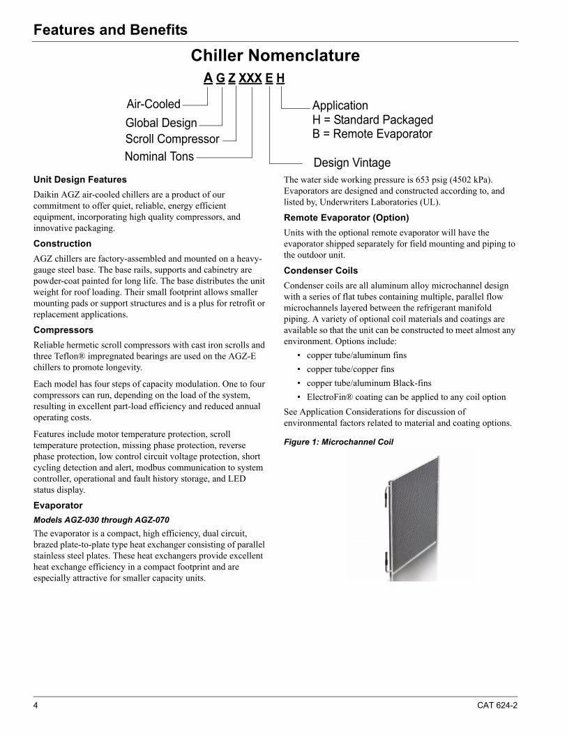
Condenser Coils
Condenser coils are all aluminum alloy microchannel design with a series of flat tubes containing multiple, parallel flow microchannels layered between the refrigerant manifold piping. A variety of optional coil materials and coatings are available so that the unit can be constructed to meet almost any environment. Options include:
• copper tube/aluminum fins
• copper tube/copper fins
• copper tube/aluminum Black-fins
• ElectroFin® coating can be applied to any coil option
See Application Considerations for discussion of environmental factors related to material and coating options.
Figure 1: Microchannel Coil
A G Z XXX E H
Air-Cooled
Global DesignScroll Compressor
Nominal Tons
Application
Design Vintage
H = Standard PackagedB = Remote Evaporator
CAT 624-2 5
Features and Benefits
Condenser Fans and Motors
Multiple direct-drive, dynamically balanced propeller fans operate in formed venturi openings at low tip speeds for maximum efficiency and minimum noise and vibration. A heavy-gauge vinyl-coated fan guard protects each fan.
Each condenser fan motor (including the optional VFD fan motor) is Totally Enclosed Air Over (TEAO), heavy-duty, 3-phase with permanently lubricated ball bearings and inherent overload protection. These motors are designed specifically for outdoor use.
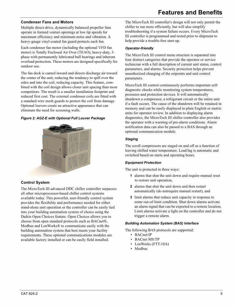
The fan deck is canted inward and directs discharge air toward the center of the unit, reducing the tendency to spill over the sides and into the coil, reducing capacity. This feature, com-bined with the coil design allows closer unit spacing than most competitors. The result is a smaller installation footprint and reduced first cost. The external condenser coils are fitted with a standard wire mesh guards to protect the coil from damage. Optional louvers create an attractive appearance that can eliminate the need for screening walls.
Figure 2: AGZ-E with Optional Full Louver Package
Control System
The MicroTech III advanced DDC chiller controller surpasses all other microprocessor-based chiller control systems available today. This powerful, user-friendly control system provides the flexibility and performance needed for either stand-alone unit operation or the controller can be easily tied into your building automation system of choice using the Daikin Open Choices feature. Open Choices allows you to choose from open standard protocols such as BACnet®, Modbus and LonWorks® to communicate easily with the building automation system that best meets your facility requirements. These optional communications modules are available factory installed or can be easily field installed.
The MicroTech III controller's design will not only permit the chiller to run more efficiently, but will also simplify troubleshooting if a system failure occurs. Every MicroTech III controller is programmed and tested prior to shipment to help provide a trouble-free start-up.
Operator-friendly
The MicroTech III control menu structure is separated into four distinct categories that provide the operator or service technician with a full description of current unit status, control parameters, and alarms. Security protection helps prevent unauthorized changing of the setpoints and unit control parameters.
MicroTech III control continuously performs important self-diagnostic checks while monitoring system temperatures, pressures and protection devices. It will automatically shutdown a compressor, a refrigerant circuit or the entire unit if a fault occurs. The cause of the shutdown will be retained in memory and can be easily displayed in plain English or metric units for operator review. In addition to displaying alarm diagnostics, the MicroTech III chiller controller also provides the operator with a warning of pre-alarm conditions. Alarm notification data can also be passed to a BAS through an optional communication module.
Staging
The scroll compressors are staged on and off as a function of leaving chilled water temperature. Lead/lag is automatic and switched based on starts and operating hours.
Equipment Protection
The unit is protected in three ways:
1 alarms that shut the unit down and require manual reset to restore unit operation,
2 alarms that shut the unit down and then restart automatically (do notrequire manual restart), and
3 limit alarms that reduce unit capacity in response to some out-of-limit condition. Shut down alarms activate an alarm signal that can be exported to a remote location. Limit alarms activate a light on the controller and do not trigger a remote alarm.
Building Automation System (BAS) Interface
The following BAS protocols are supported:• BACnet/IP• BACnet MS/TP• LonWorks (FTT-10A)• Modbus
6 CAT 624-2
Features and Benefits
Optional Remote Interface Panel
In addition to the unit-mounted user interface provided with MicroTech® III controls, the AGZ chillers can be individually equipped with a remote user interface. It provides convenient access to unit diagnostics and control adjustments without having to access a rooftop or outdoor location. One remote panel can be connected to up to eight chillers.
Features
Each remote user interface is similar to its unit-mounted counterpart and offers the same functionality and display:
• Three buttons and a navigating wheel with a 8 line by 30-character display format.
• Digital display of messages in English language.
• All operating conditions, system alarms, control parameters and schedules are monitored.
• Can be wired up to 2,300 feet (700 meters) from the unit for flexibility in placing each remote user interface within your building.
Benefits• Allows you to access the user interface for each unit
from one location, inside the building.
• Users need to learn one format because the remote user interface is identical to the unit-mounted version.
• No additional field commissioning is required for the remote user interface.
• Can be retrofit after unit installation.
• Is fully compatible with the optional BAS communication modules.
The current manual for the MicroTech® III Remote User Interface isavailable on www.DaikinApplied.com.
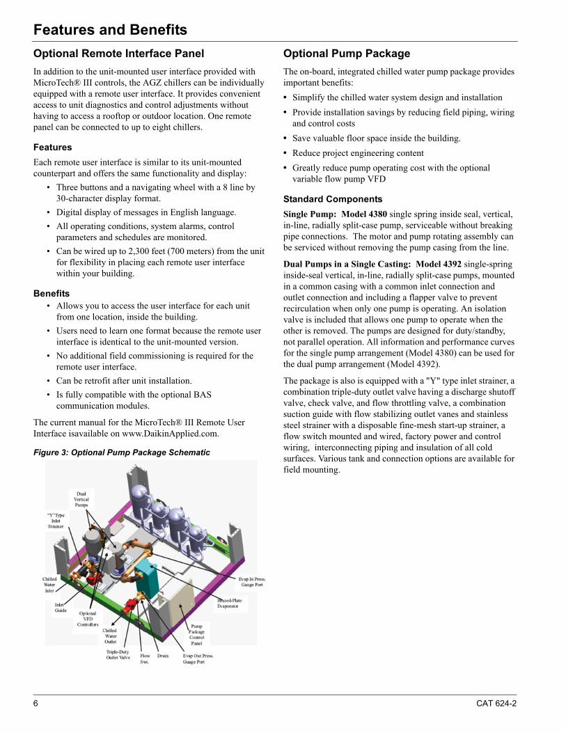
Figure 3: Optional Pump Package Schematic
Optional Pump Package
The on-board, integrated chilled water pump package provides important benefits:
• Simplify the chilled water system design and installation
• Provide installation savings by reducing field piping, wiring and control costs
• Save valuable floor space inside the building.
• Reduce project engineering content
• Greatly reduce pump operating cost with the optional variable flow pump VFD
Standard Components
Single Pump: Model 4380 single spring inside seal, vertical, in-line, radially split-case pump, serviceable without breaking pipe connections. The motor and pump rotating assembly can be serviced without removing the pump casing from the line.
Dual Pumps in a Single Casting: Model 4392 single-spring inside-seal vertical, in-line, radially split-case pumps, mounted in a common casing with a common inlet connection and outlet connection and including a flapper valve to prevent recirculation when only one pump is operating. An isolation valve is included that allows one pump to operate when the other is removed. The pumps are designed for duty/standby, not parallel operation. All information and performance curves for the single pump arrangement (Model 4380) can be used for the dual pump arrangement (Model 4392).
The package is also is equipped with a "Y" type inlet strainer, a combination triple-duty outlet valve having a discharge shutoff valve, check valve, and flow throttling valve, a combination suction guide with flow stabilizing outlet vanes and stainless steel strainer with a disposable fine-mesh start-up strainer, a flow switch mounted and wired, factory power and control wiring, interconnecting piping and insulation of all cold surfaces. Various tank and connection options are available for field mounting.
CAT 624-2 7
Features and Benefits
Optional Variable Flow VFD
The operating cost savings resulting from using variable chilled water flow via a pump VFD is well known. In the past, however, its usage has been somewhat limited by the cost and uncertainty of field installing the required system pressure differential sensors.
Daikin Applied can now offer an innovative variable chilled water flow system completely self-contained within the pump package by simply ordering the optional pump VFD-no external sensors required.
In addition to the sensorless operation, there are three other selectable operating modes:
BAS Input: The pump speed and system flow will be controlled from a customer-supplied BAS input signal.
Remote Sensor Control: The VFD is wired to a pressure sensor mounted in the chilled water piping system. This is the standard VFD control when a sensorless VFD is not used.
Locally Selected Constant Speed Control: Provides manual control of the pump speed, overriding any current automatic speed control.
Consult the current version of the installation manual for additional detailed information. It is available from the local Daikin Applied sales office or on www.DaikinApplied.com.
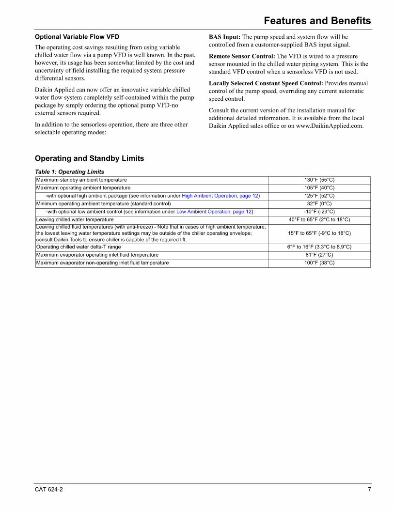
Operating and Standby Limits
Table 1: Operating LimitsMaximum standby ambient temperature 130°F (55°C)
Maximum operating ambient temperature 105°F (40°C)
-with optional high ambient package (see information under High Ambient Operation‚ page 12) 125°F (52°C)
Minimum operating ambient temperature (standard control) 32°F (0°C)
-with optional low ambient control (see information under Low Ambient Operation‚ page 12) -10°F (-23°C)
Leaving chilled water temperature 40°F to 65°F (2°C to 18°C)
Leaving chilled fluid temperatures (with anti-freeze) - Note that in cases of high ambient temperature, the lowest leaving water temperature settings may be outside of the chiller operating envelope; consult Daikin Tools to ensure chiller is capable of the required lift.
15°F to 65°F (-9°C to 18°C)
Operating chilled water delta-T range 6°F to 16°F (3.3°C to 8.9°C)
Maximum evaporator operating inlet fluid temperature 81°F (27°C)
Maximum evaporator non-operating inlet fluid temperature 100°F (38°C)
8 CAT 624-2
Application ConsiderationsApplication Considerations
Unit PlacementAGZ units are for outdoor applications and can be mounted either on a roof or at ground level. For roof mounted applications, install the unit on a steel channel or I-beam frame to support the unit above the roof. For ground level applications, install the unit on a substantial base that will not settle. Use a one-piece concrete slab with footings extended below the frost line. Be sure the foundation is level within 0.5” (13mm) over its length and width. The foundation must be strong enough to support the weights listed in the Physical Data Tables beginning on page 25.
Service Clearance
Sides: Minimum of 4 feet (1.22 m)
Control panel end: Minimum of 4 feet
Opposite control panel: Minimumof 4 feet
Air Clearance
Daikin Applied's advanced “W” coil design and open air-passage ends allow very close unit spacing and a small installation footprint. The AGZ-E fans are canted inward and reduce recirculation by directing discharge air to the center of the unit, reducing the tendency to flow outward and spill over into the coil inlet.
Sufficient clearance must be maintained between the unit and adjacent walls or other units to allow the required unit air flow to reach the coils. Failure to do so will result in a capacity reduction and an increase in power consumption. No obstructions are allowed above the unit at any height.
Spacing Requirements
In general, with a small performance penalty in some cases, AGZ-E units can be spaced at four feet from other units or a wall. Curves on the following pages give the minimum clearance for different types of installations and also capacity reduction and power increase if closer spacing is used.
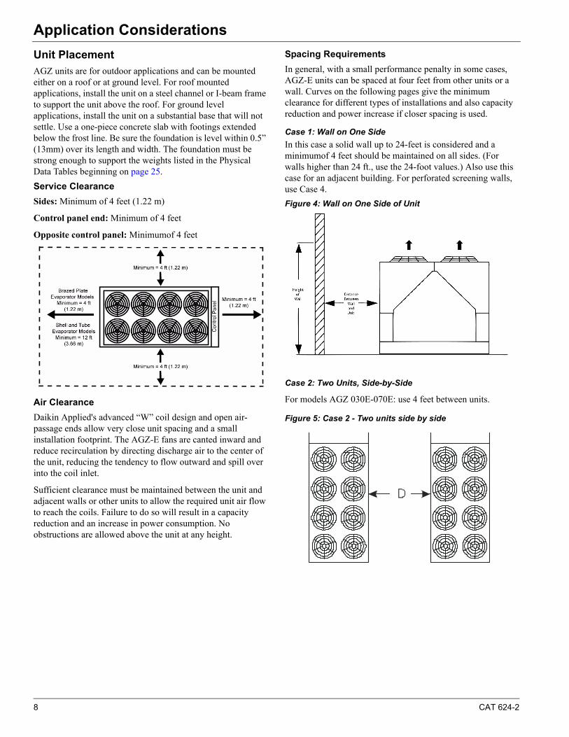
Case 1: Wall on One Side
In this case a solid wall up to 24-feet is considered and a minimumof 4 feet should be maintained on all sides. (For walls higher than 24 ft., use the 24-foot values.) Also use this case for an adjacent building. For perforated screening walls, use Case 4.
Figure 4: Wall on One Side of Unit
Case 2: Two Units, Side-by-Side
For models AGZ 030E-070E: use 4 feet between units.
Figure 5: Case 2 - Two units side by side
CAT 624-2 9
Application Considerations
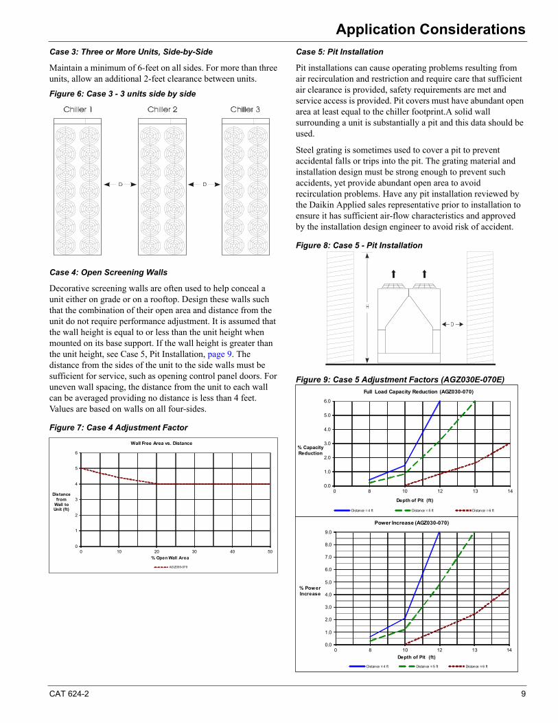
Case 3: Three or More Units, Side-by-Side
Maintain a minimum of 6-feet on all sides. For more than three units, allow an additional 2-feet clearance between units.
Figure 6: Case 3 - 3 units side by side
Case 4: Open Screening Walls
Decorative screening walls are often used to help conceal a unit either on grade or on a rooftop. Design these walls such that the combination of their open area and distance from the unit do not require performance adjustment. It is assumed that the wall height is equal to or less than the unit height when mounted on its base support. If the wall height is greater than the unit height, see Case 5, Pit Installation, page 9. The distance from the sides of the unit to the side walls must be sufficient for service, such as opening control panel doors. For uneven wall spacing, the distance from the unit to each wall can be averaged providing no distance is less than 4 feet. Values are based on walls on all four-sides.
Figure 7: Case 4 Adjustment Factor
Case 5: Pit Installation
Pit installations can cause operating problems resulting from air recirculation and restriction and require care that sufficient air clearance is provided, safety requirements are met and service access is provided. Pit covers must have abundant open area at least equal to the chiller footprint.A solid wall surrounding a unit is substantially a pit and this data should be used.
Steel grating is sometimes used to cover a pit to prevent accidental falls or trips into the pit. The grating material and installation design must be strong enough to prevent such accidents, yet provide abundant open area to avoid recirculation problems. Have any pit installation reviewed by the Daikin Applied sales representative prior to installation to ensure it has sufficient air-flow characteristics and approved by the installation design engineer to avoid risk of accident.
Figure 8: Case 5 - Pit Installation
Figure 9: Case 5 Adjustment Factors (AGZ030E-070E)
0
1
2
3
4
5
6
0 10 20 30 40 50
Distancefrom
Wall to Unit (ft)
% Open Wall Area
Wall Free Area vs. Distance
AGZ030-070
0.0
1.0
2.0
3.0
4.0
5.0
6.0
0 8 10 12 13 14
% Capacity Reduction
Depth of Pit (ft)
Full Load Capacity Reduction (AGZ030-070)
Distance = 4 ft Distance = 5 ft Distance = 6 ft
0.0
1.0
2.0
3.0
4.0
5.0
6.0
7.0
8.0
9.0
0 8 10 12 13 14
% Power Increase
Depth of Pit (ft)
Power Increase (AGZ030-070)
Distance = 4 ft Distance = 5 ft Distance = 6 ft
10 CAT 624-2
Application Considerations
Chilled Water Piping
IMPORTANT: Piping design must be provided by a qualified Architect or Systems HVAC Design Engineer familiar with piping design, as well as local codes and regulations. The manufacturer recommendations provided here are to be used as a general guide, but do not replace system design by a qualified professional.
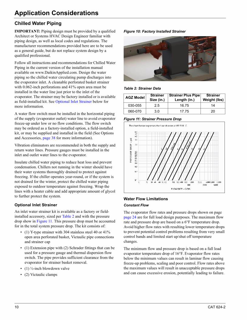
Follow all instructions and recommendations for Chilled Water Piping in the current version of the installation manual available on www.DaikinApplied.com. Design the water piping so the chilled water circulating pump discharges into the evaporator inlet. A cleanable perforated basket strainer with 0.062-inch perforations and 41% open area must be installed in the water line just prior to the inlet of the evaporator. The strainer may be factory installed or is available as field-installed kit. See Optional Inlet Strainer below for more information.
A water flow switch must be installed in the horizontal piping of the supply (evaporator outlet) water line to avoid evaporator freeze-up under low or no flow conditions. The flow switch may be ordered as a factory-installed option, a field-installed kit, or may be supplied and installed in the field (See Options and Accessories, page 38 for more information).
Vibration eliminators are recommended in both the supply and return water lines. Pressure gauges must be installed in the inlet and outlet water lines to the evaporator.
Insulate chilled water piping to reduce heat loss and prevent condensation. Chillers not running in the winter should have their water systems thoroughly drained to protect against freezing. If the chiller operates year-round, or if the system is not drained for the winter, protect the chilled water piping exposed to outdoor temperature against freezing. Wrap the lines with a heater cable and add appropriate amount of glycol to further protect the system.
Optional Inlet Strainer
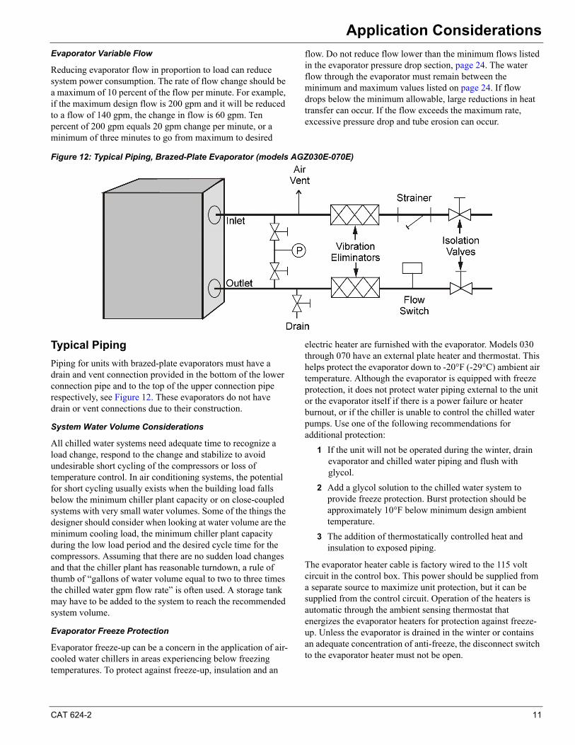
An inlet water strainer kit is available as a factory or field-installed accessory, sized per Table 2 and with the pressure drop show in Figure 11. This pressure drop must be accounted for in the total system pressure drop. The kit consists of:
• (1) Y-type strainer with 304 stainless steel 40 or 41% open area perforated basket, Victaulic pipe connections and strainer cap
• (1) Extension pipe with (2) Schrader fittings that can be used for a pressure gauge and thermal dispersion flow switch. The pipe provides sufficient clearance from the evaporator for strainer basket removal.
• (1) ½-inch blowdown valve
• (2) Victaulic clamps
Figure 10: Factory Installed Strainer
Table 2: Strainer Data
Figure 11: Strainer Pressure Drop
Water Flow Limitations
Constant Flow
The evaporator flow rates and pressure drops shown on page page 24 are for full load design purposes. The maximum flow rate and pressure drop are based on a 6°F temperature drop. Avoid higher flow rates with resulting lower temperature drops to prevent potential control problems resulting from very small control bands and limited start up/shut off temperature changes.
The minimum flow and pressure drop is based on a full load evaporator temperature drop of 16°F. Evaporator flow rates below the minimum values can result in laminar flow causing freeze-up problems, scaling and poor control. Flow rates above the maximum values will result in unacceptable pressure drops and can cause excessive erosion, potentially leading to failure.
AGZ ModelStrainer Size (in.)
Strainer Plus Pipe Length (in.)
Strainer Weight (lbs)
030-055 2.5 16.75 14
060-070 3.0 17.75 20
CAT 624-2 11
Application Considerations
Evaporator Variable Flow
Reducing evaporator flow in proportion to load can reduce system power consumption. The rate of flow change should be a maximum of 10 percent of the flow per minute. For example, if the maximum design flow is 200 gpm and it will be reduced to a flow of 140 gpm, the change in flow is 60 gpm. Ten percent of 200 gpm equals 20 gpm change per minute, or a minimum of three minutes to go from maximum to desired
flow. Do not reduce flow lower than the minimum flows listed in the evaporator pressure drop section, page 24. The water flow through the evaporator must remain between the minimum and maximum values listed on page 24. If flow drops below the minimum allowable, large reductions in heat transfer can occur. If the flow exceeds the maximum rate, excessive pressure drop and tube erosion can occur.
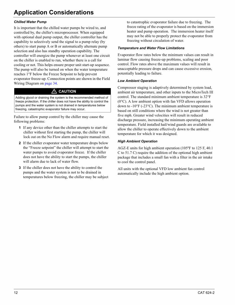
Figure 12: Typical Piping, Brazed-Plate Evaporator (models AGZ030E-070E)
Typical Piping
Piping for units with brazed-plate evaporators must have a drain and vent connection provided in the bottom of the lower connection pipe and to the top of the upper connection pipe respectively, see Figure 12. These evaporators do not have drain or vent connections due to their construction.
System Water Volume Considerations
All chilled water systems need adequate time to recognize a load change, respond to the change and stabilize to avoid undesirable short cycling of the compressors or loss of temperature control. In air conditioning systems, the potential for short cycling usually exists when the building load falls below the minimum chiller plant capacity or on close-coupled systems with very small water volumes. Some of the things the designer should consider when looking at water volume are the minimum cooling load, the minimum chiller plant capacity during the low load period and the desired cycle time for the compressors. Assuming that there are no sudden load changes and that the chiller plant has reasonable turndown, a rule of thumb of “gallons of water volume equal to two to three times the chilled water gpm flow rate” is often used. A storage tank may have to be added to the system to reach the recommended system volume.
Evaporator Freeze Protection
Evaporator freeze-up can be a concern in the application of air-cooled water chillers in areas experiencing below freezing temperatures. To protect against freeze-up, insulation and an
electric heater are furnished with the evaporator. Models 030 through 070 have an external plate heater and thermostat. This helps protect the evaporator down to -20°F (-29°C) ambient air temperature. Although the evaporator is equipped with freeze protection, it does not protect water piping external to the unit or the evaporator itself if there is a power failure or heater burnout, or if the chiller is unable to control the chilled water pumps. Use one of the following recommendations for additional protection:
1 If the unit will not be operated during the winter, drain evaporator and chilled water piping and flush with glycol.
2 Add a glycol solution to the chilled water system to provide freeze protection. Burst protection should be approximately 10°F below minimum design ambient temperature.
3 The addition of thermostatically controlled heat and insulation to exposed piping.
The evaporator heater cable is factory wired to the 115 volt circuit in the control box. This power should be supplied from a separate source to maximize unit protection, but it can be supplied from the control circuit. Operation of the heaters is automatic through the ambient sensing thermostat that energizes the evaporator heaters for protection against freeze-up. Unless the evaporator is drained in the winter or contains an adequate concentration of anti-freeze, the disconnect switch to the evaporator heater must not be open.
12 CAT 624-2
Application Considerations
Chilled Water Pump
It is important that the chilled water pumps be wired to, and controlled by, the chiller's microprocessor. When equipped with optional dual pump output, the chiller controller has the capability to selectively send the signal to a pump relay (by others) to start pump A or B or automatically alternate pump selection and also has standby operation capability. The controller will energize the pump whenever at least one circuit on the chiller is enabled to run, whether there is a call for cooling or not. This helps ensure proper unit start-up sequence. The pump will also be turned on when the water temperature reaches 1°F below the Freeze Setpoint to help prevent evaporator freeze-up. Connection points are shown in the Field Wiring Diagram on page 34.
Failure to allow pump control by the chiller may cause the following problems:
1 If any device other than the chiller attempts to start the chiller without first starting the pump, the chiller will lock out on the No Flow alarm and require manual reset.
2 If the chiller evaporator water temperature drops below the “Freeze setpoint” the chiller will attempt to start the water pumps to avoid evaporator freeze. If the chiller does not have the ability to start the pumps, the chiller will alarm due to lack of water flow.
3 If the chiller does not have the ability to control the pumps and the water system is not to be drained in temperatures below freezing, the chiller may be subject
to catastrophic evaporator failure due to freezing. The freeze rating of the evaporator is based on the immersion heater and pump operation. The immersion heater itself may not be able to properly protect the evaporator from freezing without circulation of water.
Temperature and Water Flow Limitations
Evaporator flow rates below the minimum values can result in laminar flow causing freeze-up problems, scaling and poor control. Flow rates above the maximum values will result in unacceptable pressure drops and can cause excessive erosion, potentially leading to failure.
Low Ambient Operation
Compressor staging is adaptively determined by system load, ambient air temperature, and other inputs to the MicroTech III control. The standard minimum ambient temperature is 32°F (0°C). A low ambient option with fan VFD allows operation down to -10°F (-23°C). The minimum ambient temperature is based on still conditions where the wind is not greater than five mph. Greater wind velocities will result in reduced discharge pressure, increasing the minimum operating ambient temperature. Field installed hail/wind guards are available to allow the chiller to operate effectively down to the ambient temperature for which it was designed.
High Ambient Operation
AGZ-E units for high ambient operation (105ºF to 125 F, 40.1 C to 51.7 C) require the addition of the optional high ambient package that includes a small fan with a filter in the air intake to cool the control panel.
All units with the optional VFD low ambient fan control automatically include the high ambient option.
CAUTION
Adding glycol or draining the system is the recommended method of freeze protection. If the chiller does not have the ability to control the pumps and the water system is not drained in temperatures below freezing, catastrophic evaporator failure may occur.
CAT 624-2 13
Application Considerations
Condenser Coil Options and Coating Considerations
The standard coils on the AGZ-E chiller are an all aluminum alloy microchannel design with a series of flat tubes containing multiple, parallel flow microchannels layered between the refrigerant manifolds. The microchannel coils are designed to withstand 1000+ hour acidified synthetic sea water fog (SWAAT) test (ASTM G85-02) at 120°F (49°C) with 0% fin loss and develop no leaks. The all-aluminum microchannel coils provide superior longevity and durability for non-corrosive applications.
Should the standard microchannel coil not meet the corrosion requirements for the application, additional coil options are available.
Aluminum fin/copper tube coils consist of 3/8 inch (10mm) seamless copper tubes mechanically bonded into plate-type aluminum fins. The fins have full drawn collars to completely cover the tubes. The aluminum fin/copper tube option provides excellent durability in non-corrosive environments, and adds the benefit of ease of field repair.
BlackFinTM coils include aluminum fins pre-coated with a durable phenolic epoxy coating. In addition to providing a durable coating on the fin material, the BlackFinTM coils provide and epoxy barrier between the aluminum fin stock and the copper tube, to prevent the galvanic corrosion that can occur between the dissimilar metals. This option will provide a 1000+ hour salt spray rating per ASTM B117-90. The BlackFinTM option provides an economical solution for enhanced protection in mildly corrosive environments.
Copper-fin coils consist of 3/8 inch (10mm) seamless copper tubes mechanically bonded into plate-type copper fins. The fins have full drawn collars to completely cover the tubes.
Since the fin and the tube materials are similar, the opportunity for galvanic corrosion is eliminated. The copper fin/copper tube option provides excellent longevity in marine environments; however this option is not well suited for industrial or chemical atmospheric contamination.
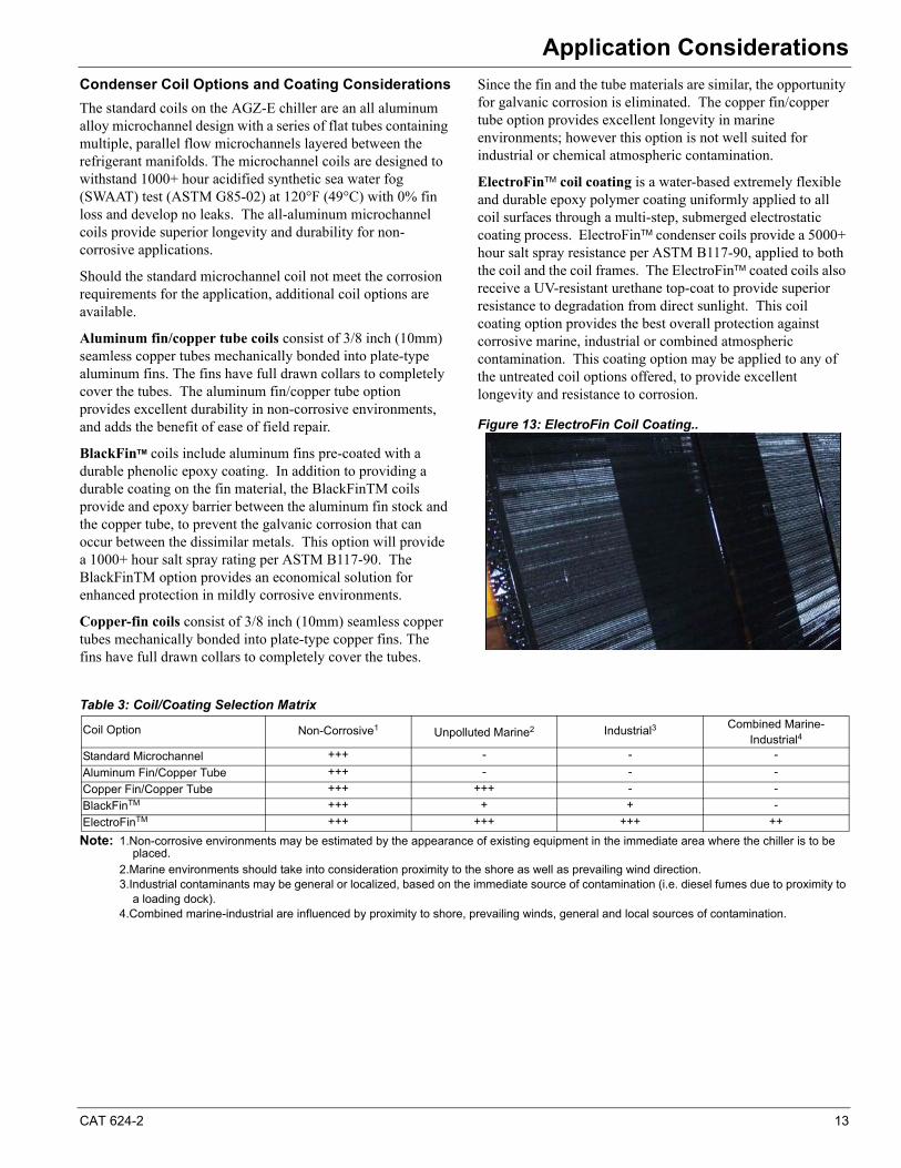
ElectroFinTM coil coating is a water-based extremely flexible and durable epoxy polymer coating uniformly applied to all coil surfaces through a multi-step, submerged electrostatic coating process. ElectroFinTM condenser coils provide a 5000+ hour salt spray resistance per ASTM B117-90, applied to both the coil and the coil frames. The ElectroFinTM coated coils also receive a UV-resistant urethane top-coat to provide superior resistance to degradation from direct sunlight. This coil coating option provides the best overall protection against corrosive marine, industrial or combined atmospheric contamination. This coating option may be applied to any of the untreated coil options offered, to provide excellent longevity and resistance to corrosion.
Figure 13: ElectroFin Coil Coating..
Note: 1.Non-corrosive environments may be estimated by the appearance of existing equipment in the immediate area where the chiller is to be placed.
2.Marine environments should take into consideration proximity to the shore as well as prevailing wind direction.3.Industrial contaminants may be general or localized, based on the immediate source of contamination (i.e. diesel fumes due to proximity to
a loading dock).4.Combined marine-industrial are influenced by proximity to shore, prevailing winds, general and local sources of contamination.
Table 3: Coil/Coating Selection Matrix
Coil Option Non-Corrosive1 Unpolluted Marine2 Industrial3 Combined Marine-Industrial4
Standard Microchannel00 +++ - - -
Aluminum Fin/Copper Tube 00 +++ - - -
Copper Fin/Copper Tube 00 +++ +++ - -
BlackFinTM +++ + + -
ElectroFinTM +++ +++ +++ ++
14 CAT 624-2
Sound DataSound Data
Sound levels can be as important as unit cost and efficiency. The inherently quiet scroll compresors used in model AGZ-E chillers are coupled with precision engineering for industry-leading sound levels.
Background
AHRI has established standards to provide uniform methods for the determination of the sound levels of equipment. For large air-cooled chillers, it is AHRI Standard 370, Sound Ratings of Large Outdoor Refrigeration and Air-Conditioning Equipment. Data contained in this section are in accordance with this standard.
“A” Weighting
Sound values may be represented several ways. One of the more common forms is the “A” weighted value, which adds or subtracts a specific amount to each center band frequency, then logarithmically adds the values to establish a single value. The “A” scale is used to represent how the human ear receives sound. The amount added in each frequency band directly corresponds to how sensitive the human ear is to each frequency.
Sound Pressure Levels - Full Load
Sound pressure is the sound level that can be measured at some distance from the source. Sound presure varies with distance from the source and depends on the surroundings. For example, a brick wall (a reflective surface) located 10 feet from a unit will affect the sound pressure measurements differently than a brick wall at 20 feet. Sound pressure is measured in decibels (dB).
All sound pressure data in the following pages are considered typical of what can be measured in a free field with a handheld sound meter, in the absence of any nearby reflective surfaces except the floor under the unit. Sound pressure levels are measured at 30 feet (10 meters) from the side of the unit at 100% load and standard AHRI conditions (per AHRI standard 550/590-2003) of 95°F (35°C) ambient air temperature and 44°F (7°C) leaving evaporator water temperatures for air-cooled units.
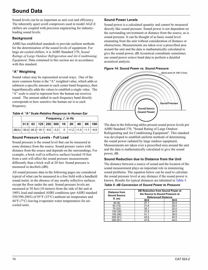
Sound Power Levels
Sound power is a calculated quantity and cannot be measured directly like sound pressure. Sound power is not dependent on the surrounding environment or distance from the source, as is sound pressure. It can be thought of as basic sound level emanating from the unit without consideration of distance or obstructions. Measurements are taken over a prescribed area around the unit and the data is mathematically calculated to give the sound power, dB.Acoustical consultants sometimes use sound power octave band data to perform a detailed acoustical analysis.
Figure 14: Sound Power vs. Sound Pressure
The data in the following tables present sound power levels per AHRI Standard 370, "Sound Rating of Large Outdoor Refrigerating and Air Conditioning Equipment". This standard was developed to establish uniform methods of determining the sound power radiated by large outdoor equipment. Measurements are taken over a prescribed area around the unit and the data is mathematically calculated to give the sound power, dB.
Sound Reduction due to Distance from the Unit
The distance between a source of sound and the location of the sound measurement plays an important role in minimizing sound problems. The equation below can be used to calculate the sound pressure level at any distance if the sound power is known. Results for typical distances are tabulated in Table 5. Table 5: dB Conversion of Sound Power to Pressure
Table 4: “A” Scale Relative Response to Human Ear
Frequency, f , in Hz
31.5 63 125 250 500 1K 2K 4K 8K 16K
dB(A) −39.4 −26.2 −16.1 −8.6 −3.2 0 +1.2 +1.0 −1.1 −6.6
Distance from Sound Source
ft. (m)
DB Reduction from Sound Power at the Source to Sound Pressure at
Referenced DistanceQ=2 Q=4
30 (9) 27.1 24.050 (15) 31.6 28.575 (23) 35.1 32.0
100 (30) 37.6 34.5150 (46) 41.1 38.0200 (61) 43.6 40.5300 (91) 47.6 44.0
CAT 624-2 15
Sound Data
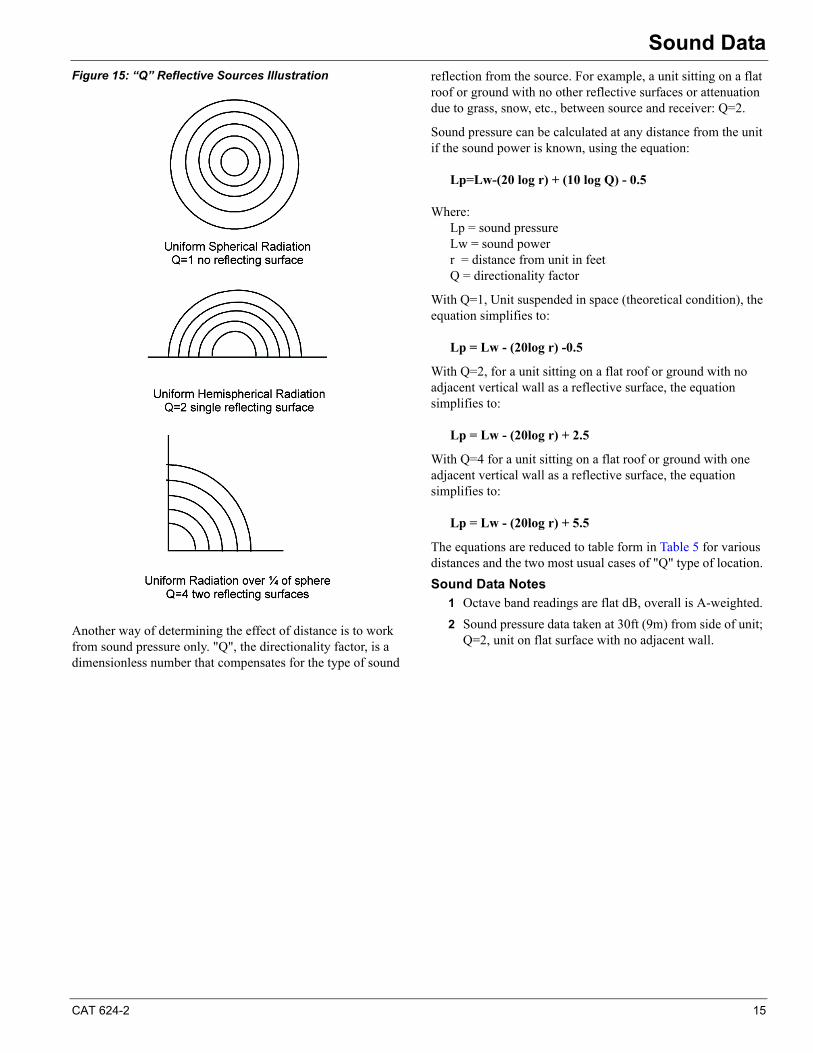
Figure 15: “Q” Reflective Sources Illustration
Another way of determining the effect of distance is to work from sound pressure only. "Q", the directionality factor, is a dimensionless number that compensates for the type of sound
reflection from the source. For example, a unit sitting on a flat roof or ground with no other reflective surfaces or attenuation due to grass, snow, etc., between source and receiver: Q=2.
Sound pressure can be calculated at any distance from the unit if the sound power is known, using the equation:
Lp=Lw-(20 log r) + (10 log Q) - 0.5
Where: Lp = sound pressureLw = sound powerr = distance from unit in feetQ = directionality factor
With Q=1, Unit suspended in space (theoretical condition), the equation simplifies to:
Lp = Lw - (20log r) -0.5
With Q=2, for a unit sitting on a flat roof or ground with no adjacent vertical wall as a reflective surface, the equation simplifies to:
Lp = Lw - (20log r) + 2.5
With Q=4 for a unit sitting on a flat roof or ground with one adjacent vertical wall as a reflective surface, the equation simplifies to:
Lp = Lw - (20log r) + 5.5
The equations are reduced to table form in Table 5 for various distances and the two most usual cases of "Q" type of location.
Sound Data Notes
1 Octave band readings are flat dB, overall is A-weighted.
2 Sound pressure data taken at 30ft (9m) from side of unit; Q=2, unit on flat surface with no adjacent wall.
16 CAT 624-2
Sound Data
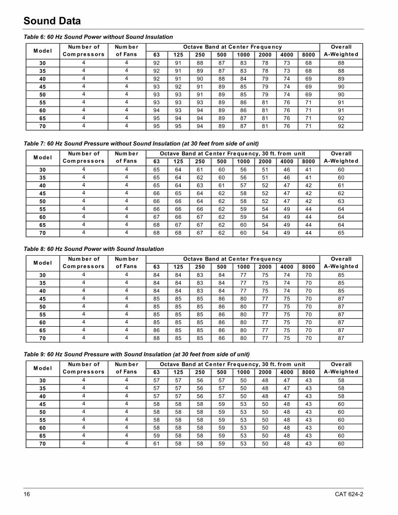
Table 6: 60 Hz Sound Power without Sound Insulation
Table 7: 60 Hz Sound Pressure without Sound Insulation (at 30 feet from side of unit)
Table 8: 60 Hz Sound Power with Sound Insulation
Table 9: 60 Hz Sound Pressure with Sound Insulation (at 30 feet from side of unit)
63 125 250 500 1000 2000 4000 8000
30 4 4 92 91 88 87 83 78 73 68 88
35 4 4 92 91 89 87 83 78 73 68 88
40 4 4 92 91 90 88 84 79 74 69 89
45 4 4 93 92 91 89 85 79 74 69 90
50 4 4 93 93 91 89 85 79 74 69 90
55 4 4 93 93 93 89 86 81 76 71 91
60 4 4 94 93 94 89 86 81 76 71 91
65 4 4 95 94 94 89 87 81 76 71 92
70 4 4 95 95 94 89 87 81 76 71 92
M ode l Ove rall
A-We ighte dNum be r of
Com pre s s orsNum be rof Fans
Octave Band at Ce nte r Fre que ncy
63 125 250 500 1000 2000 4000 8000
30 4 4 65 64 61 60 56 51 46 41 60
35 4 4 65 64 62 60 56 51 46 41 60
40 4 4 65 64 63 61 57 52 47 42 61
45 4 4 66 65 64 62 58 52 47 42 62
50 4 4 66 66 64 62 58 52 47 42 63
55 4 4 66 66 66 62 59 54 49 44 64
60 4 4 67 66 67 62 59 54 49 44 64
65 4 4 68 67 67 62 60 54 49 44 64
70 4 4 68 68 67 62 60 54 49 44 65
M ode l Ove rall
A-We ighte dNum be r of
Com pre s s orsNum be rof Fans
Octave Band at Ce nte r Fre que ncy, 30 ft. from unit
63 125 250 500 1000 2000 4000 8000
30 4 4 84 84 83 84 77 75 74 70 85
35 4 4 84 84 83 84 77 75 74 70 85
40 4 4 84 84 83 84 77 75 74 70 85
45 4 4 85 85 85 86 80 77 75 70 87
50 4 4 85 85 85 86 80 77 75 70 87
55 4 4 85 85 85 86 80 77 75 70 87
60 4 4 85 85 85 86 80 77 75 70 87
65 4 4 86 85 85 86 80 77 75 70 87
70 4 4 88 85 85 86 80 77 75 70 87
M ode l Ove rall
A-We ighte dNum be r of
Com pre s s orsNum be rof Fans
Octave Band at Ce nte r Fre que ncy
63 125 250 500 1000 2000 4000 8000
30 4 4 57 57 56 57 50 48 47 43 58
35 4 4 57 57 56 57 50 48 47 43 58
40 4 4 57 57 56 57 50 48 47 43 58
45 4 4 58 58 58 59 53 50 48 43 60
50 4 4 58 58 58 59 53 50 48 43 60
55 4 4 58 58 58 59 53 50 48 43 60
60 4 4 58 58 58 59 53 50 48 43 60
65 4 4 59 58 58 59 53 50 48 43 60
70 4 4 61 58 58 59 53 50 48 43 60
M ode l Ove rall
A-We ighte dNum be r of
Com pre s s orsNum be rof Fans
Octave Band at Ce nte r Fre que ncy, 30 ft. from unit
CAT 624-2 17
Sound Data
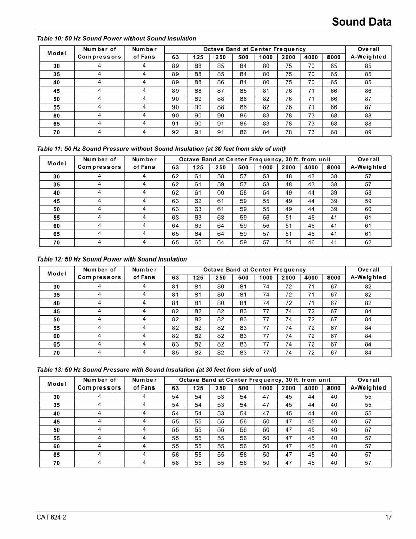
Table 10: 50 Hz Sound Power without Sound Insulation
Table 11: 50 Hz Sound Pressure without Sound Insulation (at 30 feet from side of unit)
Table 12: 50 Hz Sound Power with Sound Insulation
Table 13: 50 Hz Sound Pressure with Sound Insulation (at 30 feet from side of unit)
63 125 250 500 1000 2000 4000 8000
30 4 4 89 88 85 84 80 75 70 65 85
35 4 4 89 88 85 84 80 75 70 65 85
40 4 4 89 88 86 84 80 75 70 65 85
45 4 4 89 88 87 85 81 76 71 66 86
50 4 4 90 89 88 86 82 76 71 66 87
55 4 4 90 90 88 86 82 76 71 66 87
60 4 4 90 90 90 86 83 78 73 68 88
65 4 4 91 90 91 86 83 78 73 68 88
70 4 4 92 91 91 86 84 78 73 68 89
M ode l Ove rall
A-We ightedNum be r of
Com pre s s orsNum be rof Fans
Octave Band at Ce nte r Fre que ncy
63 125 250 500 1000 2000 4000 8000
30 4 4 62 61 58 57 53 48 43 38 57
35 4 4 62 61 59 57 53 48 43 38 57
40 4 4 62 61 60 58 54 49 44 39 58
45 4 4 63 62 61 59 55 49 44 39 59
50 4 4 63 63 61 59 55 49 44 39 60
55 4 4 63 63 63 59 56 51 46 41 61
60 4 4 64 63 64 59 56 51 46 41 61
65 4 4 65 64 64 59 57 51 46 41 61
70 4 4 65 65 64 59 57 51 46 41 62
M ode l Ove rall
A-We ightedNum be r of
Com pre s s orsNum be rof Fans
Octave Band at Ce nte r Fre que ncy, 30 ft. from unit
63 125 250 500 1000 2000 4000 8000
30 4 4 81 81 80 81 74 72 71 67 82
35 4 4 81 81 80 81 74 72 71 67 82
40 4 4 81 81 80 81 74 72 71 67 82
45 4 4 82 82 82 83 77 74 72 67 84
50 4 4 82 82 82 83 77 74 72 67 84
55 4 4 82 82 82 83 77 74 72 67 84
60 4 4 82 82 82 83 77 74 72 67 84
65 4 4 83 82 82 83 77 74 72 67 84
70 4 4 85 82 82 83 77 74 72 67 84
M ode l Ove rall
A-We ightedNum be r of
Com pre s s orsNum be rof Fans
Octave Band at Ce nte r Fre que ncy
63 125 250 500 1000 2000 4000 8000
30 4 4 54 54 53 54 47 45 44 40 55
35 4 4 54 54 53 54 47 45 44 40 55
40 4 4 54 54 53 54 47 45 44 40 55
45 4 4 55 55 55 56 50 47 45 40 57
50 4 4 55 55 55 56 50 47 45 40 57
55 4 4 55 55 55 56 50 47 45 40 57
60 4 4 55 55 55 56 50 47 45 40 57
65 4 4 56 55 55 56 50 47 45 40 57
70 4 4 58 55 55 56 50 47 45 40 57
M ode l Ove rall
A-We ightedNum be r of
Com pre s s orsNum be rof Fans
Octave Band at Ce nte r Fre que ncy, 30 ft. from unit
18 CAT 624-2
Selection ProcedureSelection Procedure
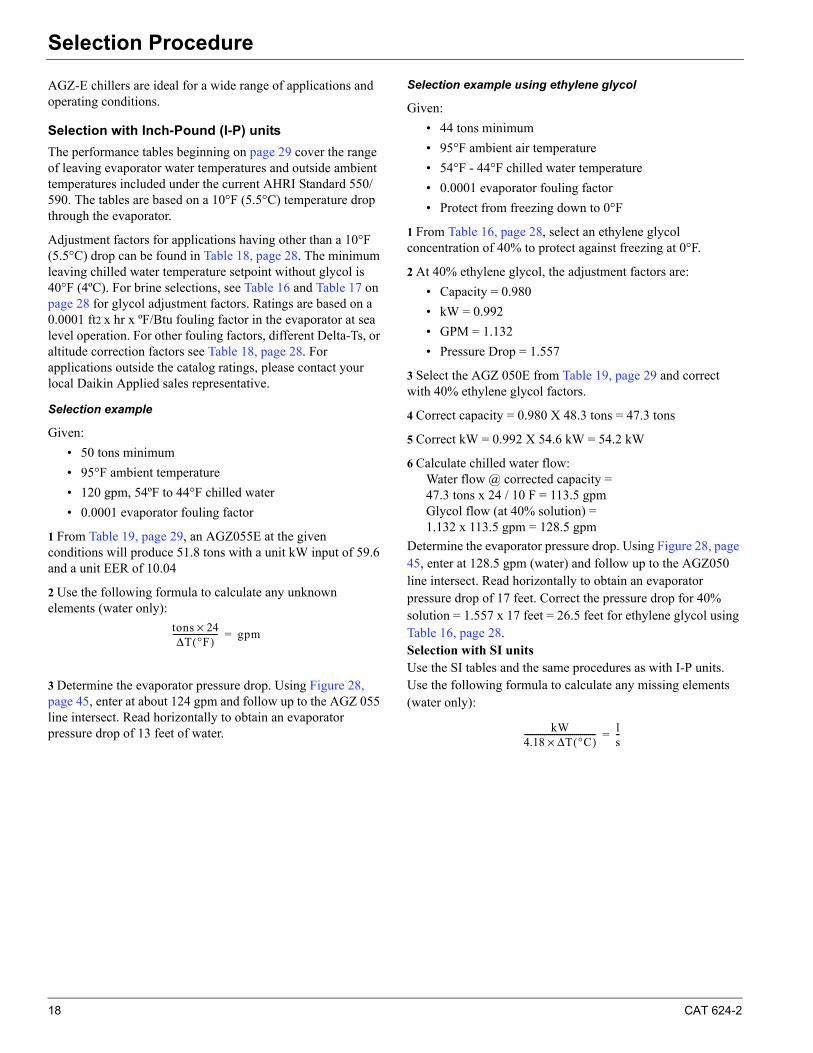
AGZ-E chillers are ideal for a wide range of applications and operating conditions.
Selection with Inch-Pound (I-P) units
The performance tables beginning on page 29 cover the range of leaving evaporator water temperatures and outside ambient temperatures included under the current AHRI Standard 550/590. The tables are based on a 10°F (5.5°C) temperature drop through the evaporator.
Adjustment factors for applications having other than a 10°F (5.5°C) drop can be found in Table 18, page 28. The minimum leaving chilled water temperature setpoint without glycol is 40°F (4ºC). For brine selections, see Table 16 and Table 17 on page 28 for glycol adjustment factors. Ratings are based on a 0.0001 ft2 x hr x ºF/Btu fouling factor in the evaporator at sea level operation. For other fouling factors, different Delta-Ts, or altitude correction factors see Table 18, page 28. For applications outside the catalog ratings, please contact your local Daikin Applied sales representative.
Selection example
Given:
• 50 tons minimum
• 95°F ambient temperature
• 120 gpm, 54ºF to 44°F chilled water
• 0.0001 evaporator fouling factor
1 From Table 19, page 29, an AGZ055E at the given conditions will produce 51.8 tons with a unit kW input of 59.6 and a unit EER of 10.04
2 Use the following formula to calculate any unknown elements (water only):
3 Determine the evaporator pressure drop. Using Figure 28, page 45, enter at about 124 gpm and follow up to the AGZ 055 line intersect. Read horizontally to obtain an evaporator pressure drop of 13 feet of water.
Selection example using ethylene glycol
Given:
• 44 tons minimum
• 95°F ambient air temperature
• 54°F - 44°F chilled water temperature
• 0.0001 evaporator fouling factor
• Protect from freezing down to 0°F
1 From Table 16, page 28, select an ethylene glycol concentration of 40% to protect against freezing at 0°F.
2 At 40% ethylene glycol, the adjustment factors are:
• Capacity = 0.980
• kW = 0.992
• GPM = 1.132
• Pressure Drop = 1.557
3 Select the AGZ 050E from Table 19, page 29 and correct with 40% ethylene glycol factors.
4 Correct capacity = 0.980 X 48.3 tons = 47.3 tons
5 Correct kW = 0.992 X 54.6 kW = 54.2 kW
6 Calculate chilled water flow:Water flow @ corrected capacity =47.3 tons x 24 / 10 F = 113.5 gpmGlycol flow (at 40% solution) =1.132 x 113.5 gpm = 128.5 gpm
Determine the evaporator pressure drop. Using Figure 28, page 45, enter at 128.5 gpm (water) and follow up to the AGZ050 line intersect. Read horizontally to obtain an evaporator pressure drop of 17 feet. Correct the pressure drop for 40% solution = 1.557 x 17 feet = 26.5 feet for ethylene glycol using Table 16, page 28.Selection with SI unitsUse the SI tables and the same procedures as with I-P units. Use the following formula to calculate any missing elements (water only):
tons 24×ΔT °F( )
----------------------- gpm=
kW4.18 ΔT °C( )×------------------------------------ l
s--=
CAT 624-2 19
Performance DataPerformance Data
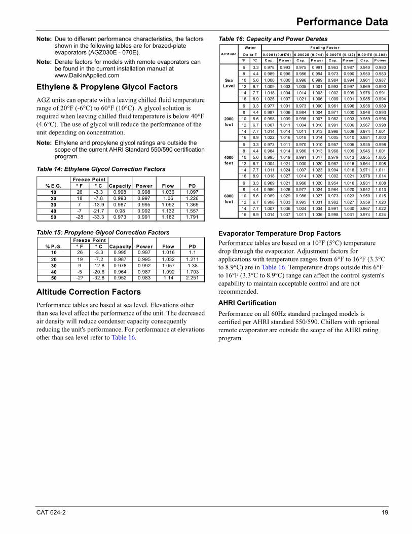
Note: Due to different performance characteristics, the factors shown in the following tables are for brazed-plate evaporators (AGZ030E - 070E).
Note: Derate factors for models with remote evaporators can be found in the current installation manual at www.DaikinApplied.com
Ethylene & Propylene Glycol Factors
AGZ units can operate with a leaving chilled fluid temperature range of 20°F (-6°C) to 60°F (10°C). A glycol solution is required when leaving chilled fluid temperature is below 40°F (4.6°C). The use of glycol will reduce the performance of the unit depending on concentration.
Note: Ethylene and propylene glycol ratings are outside the scope of the current AHRI Standard 550/590 certification program.
Table 14: Ethylene Glycol Correction Factors
Table 15: Propylene Glycol Correction Factors
Altitude Correction Factors
Performance tables are based at sea level. Elevations other than sea level affect the performance of the unit. The decreased air density will reduce condenser capacity consequently reducing the unit's performance. For performance at elevations other than sea level refer to Table 16.
Table 16: Capacity and Power Derates
Evaporator Temperature Drop Factors
Performance tables are based on a 10°F (5°C) temperature drop through the evaporator. Adjustment factors for applications with temperature ranges from 6°F to 16°F (3.3°C to 8.9°C) are in Table 16. Temperature drops outside this 6°F to 16°F (3.3°C to 8.9°C) range can affect the control system's capability to maintain acceptable control and are not recommended.
AHRI Certification
Performance on all 60Hz standard packaged models is certified per AHRI standard 550/590. Chillers with optional remote evaporator are outside the scope of the AHRI rating program.
° F ° C10 26 -3.3 0.998 0.998 1.036 1.09720 18 -7.8 0.993 0.997 1.06 1.22630 7 -13.9 0.987 0.995 1.092 1.36940 -7 -21.7 0.98 0.992 1.132 1.55750 -28 -33.3 0.973 0.991 1.182 1.791
PD% E.G.Freeze Point
Capacity Power Flow
° F ° C10 26 -3.3 0.995 0.997 1.016 1.1
20 19 -7.2 0.987 0.995 1.032 1.21130 9 -12.8 0.978 0.992 1.057 1.3840 -5 -20.6 0.964 0.987 1.092 1.70350 -27 -32.8 0.952 0.983 1.14 2.251
Flow PDCapacity% P.G.Freeze Point
Pow er
°F °C C ap. P o we r C a p. P o we r C ap. P o wer C ap. P o we r
6 3.3 0.978 0.993 0.975 0.991 0.963 0.987 0.940 0.980
8 4.4 0.989 0.996 0.986 0.994 0.973 0.990 0.950 0.983
10 5.6 1.000 1.000 0.996 0.999 0.984 0.994 0.961 0.987
12 6.7 1.009 1.003 1.005 1.001 0.993 0.997 0.969 0.990
14 7.7 1.018 1.004 1.014 1.003 1.002 0.999 0.978 0.991
16 8.9 1.025 1.007 1.021 1.006 1.009 1.001 0.985 0.994
6 3.3 0.977 1.001 0.973 1.000 0.961 0.996 0.938 0.989
8 4.4 0.987 1.006 0.984 1.004 0.971 1.000 0.948 0.993
10 5.6 0.998 1.009 0.995 1.007 0.982 1.003 0.959 0.996
12 6.7 1.007 1.011 1.004 1.010 0.991 1.006 0.967 0.998
14 7.7 1.014 1.014 1.011 1.013 0.998 1.009 0.974 1.001
16 8.9 1.022 1.016 1.018 1.014 1.005 1.010 0.981 1.003
6 3.3 0.973 1.011 0.970 1.010 0.957 1.006 0.935 0.998
8 4.4 0.984 1.014 0.980 1.013 0.968 1.009 0.945 1.001
10 5.6 0.995 1.019 0.991 1.017 0.979 1.013 0.955 1.005
12 6.7 1.004 1.021 1.000 1.020 0.987 1.016 0.964 1.008
14 7.7 1.011 1.024 1.007 1.023 0.994 1.018 0.971 1.011
16 8.9 1.018 1.027 1.014 1.026 1.002 1.021 0.978 1.014
6 3.3 0.969 1.021 0.966 1.020 0.954 1.016 0.931 1.008
8 4.4 0.980 1.026 0.977 1.024 0.964 1.020 0.942 1.013
10 5.6 0.989 1.029 0.986 1.027 0.973 1.023 0.950 1.015
12 6.7 0.998 1.033 0.995 1.031 0.982 1.027 0.959 1.020
14 7.7 1.007 1.036 1.004 1.034 0.991 1.030 0.967 1.022
16 8.9 1.014 1.037 1.011 1.036 0.998 1.031 0.974 1.024
Water
D e lta T
F o uling F acto r
0 .000 1 (0 .0 176 ) 0 .000 25 (0 .04 4) 0 .00 075 (0 .132 ) 0 .0 017 5 (0 .3 08)
Sea Level
2000 feet
4000 feet
6000 feet
A lt itude
20 CAT 624-2
Performance Data
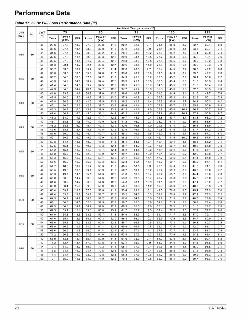
Table 17: 60 Hz Full Load Performance Data (IP)
40 29.6 27.3 13.0 27.9 29.8 11.2 26.2 32.6 9.7 24.5 35.8 8.2 22.7 39.4 6.9
42 30.6 27.5 13.4 28.9 30.0 11.6 27.2 32.8 9.9 25.4 36.0 8.5 23.6 39.7 7.1
44 31.6 27.7 13.7 29.9 30.2 11.9 28.1 33.0 10.2 26.3 36.2 8.7 24.4 39.9 7.4
46 32.6 27.8 14.1 30.8 30.3 12.2 29.0 33.1 10.5 27.2 36.3 9.0 25.2 40.1 7.6
48 33.5 27.9 14.4 31.7 30.4 12.5 29.8 33.3 10.8 27.9 36.5 9.2 26.0 40.2 7.8
50 34.3 28.1 14.7 32.4 30.6 12.7 30.6 33.4 11.0 28.6 36.6 9.4 26.6 40.3 7.9
40 36.7 33.5 13.2 34.7 36.7 11.4 32.6 40.3 9.7 30.4 44.5 8.2 28.0 49.2 6.8
42 38.0 33.8 13.5 35.9 37.0 11.7 33.8 40.7 10.0 31.5 44.9 8.4 29.0 49.7 7.0
44 39.2 34.0 13.8 37.1 37.2 11.9 34.9 41.0 10.2 32.5 45.2 8.6 30.1 50.0 7.2
46 40.3 34.2 14.1 38.2 37.4 12.2 35.9 41.1 10.5 33.5 45.4 8.9 31.0 50.3 7.4
48 41.4 34.3 14.5 39.2 37.5 12.5 36.9 41.3 10.7 34.5 45.5 9.1 31.9 50.4 7.6
50 42.3 34.5 14.7 40.1 37.7 12.8 37.7 41.4 10.9 35.3 45.6 9.3 32.7 50.5 7.8
40 41.0 33.8 14.6 38.9 37.0 12.6 36.6 40.7 10.8 34.2 44.9 9.1 31.6 49.7 7.6
42 42.5 34.0 15.0 40.2 37.2 13.0 37.9 40.9 11.1 35.5 45.2 9.4 32.9 50.1 7.9
44 43.8 34.3 15.3 41.6 37.5 13.3 39.2 41.2 11.4 36.7 45.4 9.7 34.1 50.3 8.1
46 45.1 34.5 15.7 42.8 37.7 13.6 40.4 41.4 11.7 37.9 45.7 9.9 35.2 50.6 8.3
48 46.3 34.7 16.0 43.9 37.9 13.9 41.5 41.6 12.0 38.9 45.8 10.2 36.2 50.7 8.6
50 47.4 34.9 16.3 45.0 38.1 14.2 42.5 41.7 12.2 39.9 46.0 10.4 37.1 50.9 8.7
40 45.2 38.0 14.3 42.5 41.7 12.2 39.7 45.9 10.4 36.8 50.7 8.7 33.8 56.2 7.2
42 46.7 38.3 14.6 44.0 42.0 12.6 41.2 46.2 10.7 38.2 51.1 9.0 35.1 56.6 7.4
44 48.2 38.6 15.0 45.4 42.3 12.9 42.6 46.5 11.0 39.6 51.4 9.2 36.4 56.9 7.7
46 49.6 38.8 15.4 46.8 42.5 13.2 43.9 46.7 11.3 40.8 51.6 9.5 37.7 57.2 7.9
48 51.0 39.0 15.7 48.1 42.7 13.5 45.1 46.9 11.5 42.0 51.8 9.7 38.8 57.3 8.1
50 52.1 39.2 16.0 49.2 42.9 13.8 46.2 47.1 11.8 43.1 51.9 10.0 39.8 57.5 8.3
40 50.8 44.6 13.6 48.0 48.8 11.8 45.1 53.6 10.1 42.1 59.1 8.6 38.8 65.2 7.1
42 52.5 45.1 14.0 49.7 49.3 12.1 46.7 54.2 10.3 43.6 59.7 8.8 40.2 65.9 7.3
44 54.2 45.4 14.3 51.3 49.7 12.4 48.2 54.6 10.6 45.1 60.1 9.0 41.6 66.4 7.5
46 55.8 45.6 14.7 52.8 49.9 12.7 49.7 54.8 10.9 46.4 60.5 9.2 42.9 66.8 7.7
48 57.3 45.8 15.0 54.2 50.1 13.0 51.1 55.0 11.1 47.7 60.6 9.4 44.1 67.0 7.9
50 58.6 46.0 15.3 55.5 50.3 13.2 52.3 55.1 11.4 48.9 60.7 9.7 45.2 67.1 8.1
40 54.7 48.8 13.4 51.7 53.3 11.6 48.5 58.5 9.9 45.1 64.4 8.4 41.5 71.1 7.0
42 56.5 49.3 13.8 53.4 53.9 11.9 50.2 59.1 10.2 46.7 65.1 8.6 43.0 72.0 7.2
44 58.3 49.7 14.1 55.1 54.3 12.2 51.8 59.6 10.4 48.2 65.7 8.8 44.4 72.6 7.3
46 60.0 50.0 14.4 56.8 54.6 12.5 53.3 59.9 10.7 49.7 66.0 9.0 45.8 73.0 7.5
48 61.6 50.2 14.7 58.3 54.8 12.8 54.8 60.1 10.9 51.1 66.2 9.3 47.1 73.2 7.7
50 63.0 50.4 15.0 59.6 55.0 13.0 56.1 60.3 11.2 52.3 66.3 9.5 48.3 73.3 7.9
40 60.4 53.2 13.6 57.0 58.0 11.8 53.4 63.6 10.1 49.5 70.0 8.5 45.4 77.3 7.0
42 62.4 53.8 13.9 58.9 58.7 12.0 55.2 64.3 10.3 51.2 70.8 8.7 47.1 78.3 7.2
44 64.3 54.2 14.2 60.8 59.2 12.3 57.0 64.9 10.5 52.9 71.5 8.9 48.7 79.0 7.4
46 66.1 54.6 14.5 62.5 59.5 12.6 58.7 65.3 10.8 54.6 71.9 9.1 50.2 79.4 7.6
48 67.9 54.8 14.9 64.2 59.8 12.9 60.3 65.5 11.0 56.1 72.1 9.3 51.6 79.7 7.8
50 69.3 55.1 15.1 65.6 60.0 13.1 61.7 65.7 11.3 57.4 72.2 9.5 52.9 79.7 8.0
40 61.9 54.8 13.5 58.5 59.7 11.8 54.9 65.3 10.1 51.1 71.7 8.5 47.0 79.1 7.1
42 64.0 55.4 13.9 60.5 60.3 12.0 56.8 66.0 10.3 52.9 72.5 8.8 48.7 80.0 7.3
44 66.0 55.8 14.2 62.5 60.8 12.3 58.7 66.5 10.6 54.7 73.1 9.0 50.4 80.7 7.5
46 67.9 56.2 14.5 64.3 61.1 12.6 60.4 66.9 10.8 56.3 73.5 9.2 52.0 81.1 7.7
48 69.6 56.5 14.8 66.0 61.4 12.9 62.1 67.1 11.1 57.9 73.7 9.4 53.5 81.3 7.9
50 71.2 56.8 15.0 67.5 61.6 13.1 63.5 67.3 11.3 59.3 73.9 9.6 54.8 81.4 8.1
40 68.9 63.1 13.1 65.1 69.0 11.3 61.0 75.9 9.7 56.7 83.6 8.1 52.2 92.4 6.8
42 71.2 63.7 13.4 67.2 69.8 11.6 63.1 76.7 9.9 58.7 84.6 8.3 54.1 93.6 6.9
44 73.4 64.2 13.7 69.3 70.3 11.8 65.1 77.3 10.1 60.6 85.4 8.5 55.9 94.5 7.1
46 75.5 64.5 14.0 71.4 70.6 12.1 67.0 77.7 10.4 62.5 85.8 8.7 57.6 95.0 7.3
48 77.4 64.7 14.3 73.2 70.8 12.4 68.8 77.9 10.6 64.2 86.0 9.0 59.2 95.3 7.5
50 79.1 65.0 14.6 74.9 71.0 12.6 70.4 78.0 10.8 65.7 86.1 9.2 60.7 95.3 7.6
Unit Size
HzLWT (ºF)
Am bie nt Te m pe rature (ºF)
75 85 95 105 115
TonsPow e r
(k W)EER Tons
Pow e r (k W)
EER TonsPow e r
(k W)EER Tons
Pow e r (k W)
EER TonsPow e r
(k W)EER
030 60
035 60
040 60
045 60
050 60
055 60
060 60
065 60
070 60
CAT 624-2 21
Performance Data
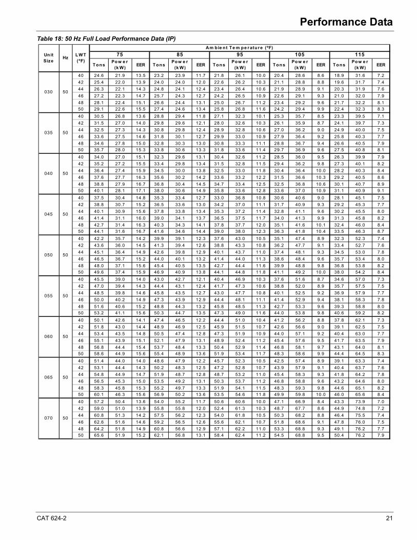
Table 18: 50 Hz Full Load Performance Data (IP)
40 24.6 21.9 13.5 23.2 23.9 11.7 21.8 26.1 10.0 20.4 28.6 8.6 18.9 31.6 7.2
42 25.4 22.0 13.9 24.0 24.0 12.0 22.6 26.2 10.3 21.1 28.8 8.8 19.6 31.7 7.4
44 26.3 22.1 14.3 24.8 24.1 12.4 23.4 26.4 10.6 21.9 28.9 9.1 20.3 31.9 7.6
46 27.2 22.3 14.7 25.7 24.3 12.7 24.2 26.5 10.9 22.6 29.1 9.3 21.0 32.0 7.9
48 28.1 22.4 15.1 26.6 24.4 13.1 25.0 26.7 11.2 23.4 29.2 9.6 21.7 32.2 8.1
50 29.1 22.6 15.5 27.4 24.6 13.4 25.8 26.8 11.6 24.2 29.4 9.9 22.4 32.3 8.3
40 30.5 26.8 13.6 28.8 29.4 11.8 27.1 32.3 10.1 25.3 35.7 8.5 23.3 39.5 7.1
42 31.5 27.0 14.0 29.8 29.6 12.1 28.0 32.6 10.3 26.1 35.9 8.7 24.1 39.7 7.3
44 32.5 27.3 14.3 30.8 29.8 12.4 28.9 32.8 10.6 27.0 36.2 9.0 24.9 40.0 7.5
46 33.6 27.5 14.6 31.8 30.1 12.7 29.9 33.0 10.9 27.9 36.4 9.2 25.8 40.3 7.7
48 34.6 27.8 15.0 32.8 30.3 13.0 30.8 33.3 11.1 28.8 36.7 9.4 26.6 40.5 7.9
50 35.7 28.0 15.3 33.8 30.6 13.3 31.8 33.6 11.4 29.7 36.9 9.6 27.5 40.8 8.1
40 34.0 27.0 15.1 32.3 29.6 13.1 30.4 32.6 11.2 28.5 36.0 9.5 26.3 39.9 7.9
42 35.2 27.2 15.5 33.4 29.8 13.4 31.5 32.8 11.5 29.4 36.2 9.8 27.3 40.1 8.2
44 36.4 27.4 15.9 34.5 30.0 13.8 32.5 33.0 11.8 30.4 36.4 10.0 28.2 40.3 8.4
46 37.6 27.7 16.3 35.6 30.2 14.2 33.6 33.2 12.2 31.5 36.6 10.3 29.2 40.5 8.6
48 38.8 27.9 16.7 36.8 30.4 14.5 34.7 33.4 12.5 32.5 36.8 10.6 30.1 40.7 8.9
50 40.1 28.1 17.1 38.0 30.6 14.9 35.8 33.6 12.8 33.6 37.0 10.9 31.1 40.9 9.1
40 37.5 30.4 14.8 35.3 33.4 12.7 33.0 36.8 10.8 30.6 40.6 9.0 28.1 45.1 7.5
42 38.8 30.7 15.2 36.5 33.6 13.0 34.2 37.0 11.1 31.7 40.9 9.3 29.2 45.3 7.7
44 40.1 30.9 15.6 37.8 33.8 13.4 35.3 37.2 11.4 32.8 41.1 9.6 30.2 45.5 8.0
46 41.4 31.1 16.0 39.0 34.1 13.7 36.5 37.5 11.7 34.0 41.3 9.9 31.3 45.8 8.2
48 42.7 31.4 16.3 40.3 34.3 14.1 37.8 37.7 12.0 35.1 41.6 10.1 32.4 46.0 8.4
50 44.1 31.6 16.7 41.6 34.6 14.4 39.0 38.0 12.3 36.3 41.8 10.4 33.5 46.3 8.7
40 42.2 35.7 14.2 39.9 39.1 12.3 37.6 43.0 10.5 35.1 47.4 8.9 32.3 52.3 7.4
42 43.6 36.0 14.5 41.3 39.4 12.6 38.8 43.3 10.8 36.2 47.7 9.1 33.4 52.7 7.6
44 45.1 36.4 14.9 42.6 39.8 12.9 40.1 43.7 11.0 37.4 48.1 9.3 34.5 53.0 7.8
46 46.5 36.7 15.2 44.0 40.1 13.2 41.4 44.0 11.3 38.6 48.4 9.6 35.7 53.4 8.0
48 48.0 37.1 15.6 45.4 40.5 13.5 42.7 44.4 11.6 39.9 48.8 9.8 36.8 53.8 8.2
50 49.6 37.4 15.9 46.9 40.9 13.8 44.1 44.8 11.8 41.1 49.2 10.0 38.0 54.2 8.4
40 45.5 39.0 14.0 43.0 42.7 12.1 40.4 46.9 10.3 37.6 51.6 8.7 34.6 57.0 7.3
42 47.0 39.4 14.3 44.4 43.1 12.4 41.7 47.3 10.6 38.8 52.0 8.9 35.7 57.5 7.5
44 48.5 39.8 14.6 45.8 43.5 12.7 43.0 47.7 10.8 40.1 52.5 9.2 36.9 57.9 7.7
46 50.0 40.2 14.9 47.3 43.9 12.9 44.4 48.1 11.1 41.4 52.9 9.4 38.1 58.3 7.8
48 51.6 40.6 15.2 48.8 44.3 13.2 45.8 48.5 11.3 42.7 53.3 9.6 39.3 58.8 8.0
50 53.2 41.1 15.6 50.3 44.7 13.5 47.3 49.0 11.6 44.0 53.8 9.8 40.6 59.2 8.2
40 50.1 42.6 14.1 47.4 46.5 12.2 44.4 51.0 10.4 41.2 56.2 8.8 37.8 62.1 7.3
42 51.8 43.0 14.4 48.9 46.9 12.5 45.9 51.5 10.7 42.6 56.6 9.0 39.1 62.5 7.5
44 53.4 43.5 14.8 50.5 47.4 12.8 47.3 51.9 10.9 44.0 57.1 9.2 40.4 63.0 7.7
46 55.1 43.9 15.1 52.1 47.9 13.1 48.9 52.4 11.2 45.4 57.6 9.5 41.7 63.5 7.9
48 56.8 44.4 15.4 53.7 48.4 13.3 50.4 52.9 11.4 46.8 58.1 9.7 43.1 64.0 8.1
50 58.6 44.9 15.6 55.4 48.9 13.6 51.9 53.4 11.7 48.3 58.6 9.9 44.4 64.5 8.3
40 51.4 44.0 14.0 48.6 47.9 12.2 45.7 52.3 10.5 42.5 57.4 8.9 39.1 63.3 7.4
42 53.1 44.4 14.3 50.2 48.3 12.5 47.2 52.8 10.7 43.9 57.9 9.1 40.4 63.7 7.6
44 54.8 44.9 14.7 51.9 48.7 12.8 48.7 53.2 11.0 45.4 58.3 9.3 41.8 64.2 7.8
46 56.5 45.3 15.0 53.5 49.2 13.1 50.3 53.7 11.2 46.8 58.8 9.6 43.2 64.6 8.0
48 58.3 45.8 15.3 55.2 49.7 13.3 51.9 54.1 11.5 48.3 59.3 9.8 44.6 65.1 8.2
50 60.1 46.3 15.6 56.9 50.2 13.6 53.5 54.6 11.8 49.9 59.8 10.0 46.0 65.6 8.4
40 57.2 50.4 13.6 54.0 55.2 11.7 50.6 60.6 10.0 47.1 66.9 8.4 43.3 73.9 7.0
42 59.0 51.0 13.9 55.8 55.8 12.0 52.4 61.3 10.3 48.7 67.7 8.6 44.9 74.8 7.2
44 60.8 51.3 14.2 57.5 56.2 12.3 54.0 61.8 10.5 50.3 68.2 8.8 46.4 75.5 7.4
46 62.6 51.6 14.6 59.2 56.5 12.6 55.6 62.1 10.7 51.8 68.6 9.1 47.8 76.0 7.5
48 64.2 51.8 14.9 60.8 56.6 12.9 57.1 62.2 11.0 53.3 68.8 9.3 49.1 76.2 7.7
50 65.6 51.9 15.2 62.1 56.8 13.1 58.4 62.4 11.2 54.5 68.8 9.5 50.4 76.2 7.9
Unit Size
HzLWT (ºF)
Am bie nt Te m pe r atur e (ºF)
75 85 95 105 115
TonsPo w e r
(k W)EER Tons
Pow e r (k W)
EER Ton sPow e r
(k W)EER Ton s
Pow e r (k W)
EER To nsPow e r
(k W)EER
030 50
035 50
040 50
045 50
050 50
055 50
060 50
065 50
070 50
22 CAT 624-2
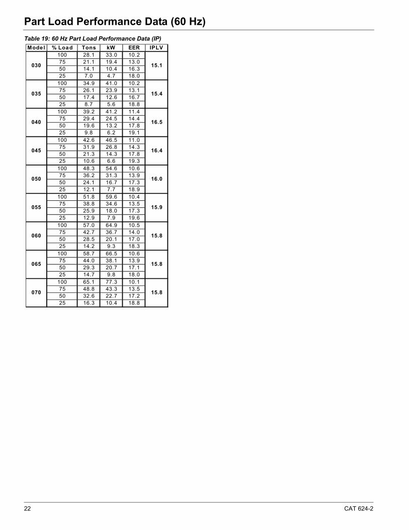
Part Load Performance Data (60 Hz)Part Load Performance Data (60 Hz)
Table 19: 60 Hz Part Load Performance Data (IP)
Mode l % Load Tons kW EER IPLV100 28.1 33.0 10.275 21.1 19.4 13.050 14.1 10.4 16.325 7.0 4.7 18.0
100 34.9 41.0 10.275 26.1 23.9 13.150 17.4 12.6 16.725 8.7 5.6 18.8
100 39.2 41.2 11.475 29.4 24.5 14.450 19.6 13.2 17.825 9.8 6.2 19.1
100 42.6 46.5 11.075 31.9 26.8 14.350 21.3 14.3 17.825 10.6 6.6 19.3
100 48.3 54.6 10.675 36.2 31.3 13.950 24.1 16.7 17.325 12.1 7.7 18.9
100 51.8 59.6 10.475 38.8 34.6 13.550 25.9 18.0 17.325 12.9 7.9 19.6
100 57.0 64.9 10.575 42.7 36.7 14.050 28.5 20.1 17.025 14.2 9.3 18.3
100 58.7 66.5 10.675 44.0 38.1 13.950 29.3 20.7 17.125 14.7 9.8 18.0
100 65.1 77.3 10.175 48.8 43.3 13.550 32.6 22.7 17.225 16.3 10.4 18.8
030 15.1
035 15.4
040 16.5
045 16.4
050 16.0
055 15.9
060 15.8
070 15.8
065 15.8
CAT 624-2 23
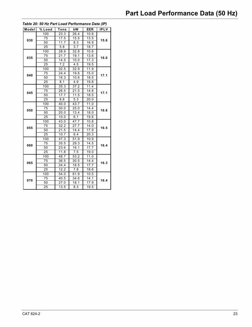
Part Load Performance Data (50 Hz)Part Load Performance Data (50 Hz)
Table 20: 50 Hz Part Load Performance Data (IP)
Mode l % Load Tons kW EER IPLV100 23.3 26.4 10.675 17.5 15.5 13.550 11.7 8.3 16.925 5.8 3.7 18.7
100 28.9 32.8 10.675 21.7 19.1 13.650 14.5 10.0 17.325 7.2 4.5 19.5
100 32.5 32.9 11.975 24.4 19.6 15.050 16.3 10.6 18.525 8.1 4.9 19.8
100 35.3 37.2 11.475 26.5 21.5 14.850 17.7 11.5 18.525 8.8 5.3 20.0
100 40.0 43.7 11.075 30.0 25.0 14.450 20.0 13.4 18.025 10.0 6.1 19.6
100 43.0 47.7 10.875 32.2 27.7 14.050 21.5 14.4 17.925 10.7 6.4 20.3
100 47.3 51.9 10.975 35.5 29.3 14.550 23.6 16.1 17.725 11.8 7.5 19.0
100 48.7 53.2 11.075 36.5 30.5 14.450 24.4 16.5 17.725 12.2 7.8 18.6
100 54.0 61.9 10.575 40.5 34.6 14.150 27.0 18.1 17.925 13.5 8.3 19.5
030 15.6
035 16.0
040 17.1
045 17.1
050 16.6
055 16.5
060 16.4
070 16.4
065 16.3
24 CAT 624-2
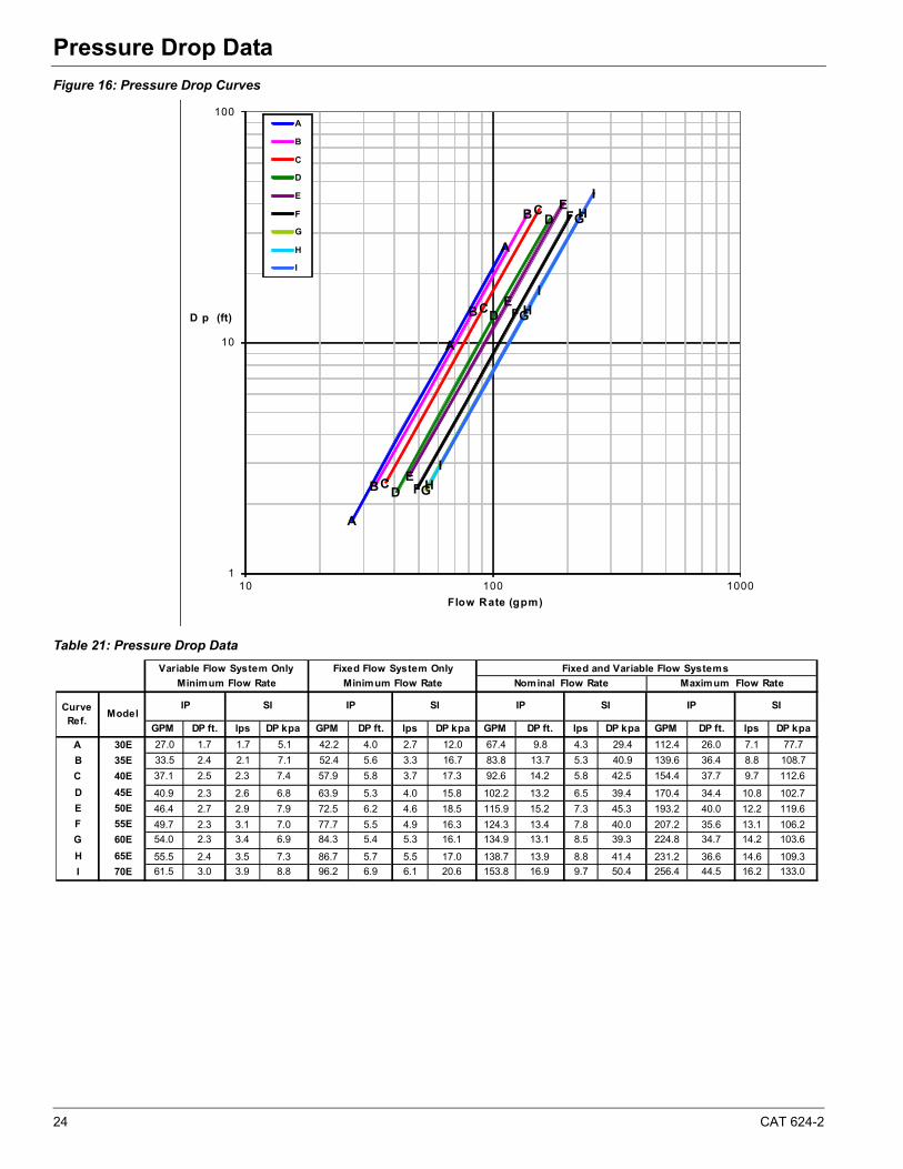
Pressure Drop DataPressure Drop Data
Figure 16: Pressure Drop Curves
Table 21: Pressure Drop Data
A
A
A
B
B
B
C
C
C
D
D
D
E
E
E
F
F
F
G
G
G
H
H
H
I
I
I
1
10
100
10 100 1000
D p (ft)
Flow Rate (gpm)
A
B
C
D
E
F
G
H
I
GPM DP ft. lps DP kpa GPM DP ft. lps DP kpa GPM DP ft. lps DP kpa GPM DP ft. lps DP kpa
A 30E 27.0 1.7 1.7 5.1 42.2 4.0 2.7 12.0 67.4 9.8 4.3 29.4 112.4 26.0 7.1 77.7
B 35E 33.5 2.4 2.1 7.1 52.4 5.6 3.3 16.7 83.8 13.7 5.3 40.9 139.6 36.4 8.8 108.7
C 40E 37.1 2.5 2.3 7.4 57.9 5.8 3.7 17.3 92.6 14.2 5.8 42.5 154.4 37.7 9.7 112.6
D 45E 40.9 2.3 2.6 6.8 63.9 5.3 4.0 15.8 102.2 13.2 6.5 39.4 170.4 34.4 10.8 102.7
E 50E 46.4 2.7 2.9 7.9 72.5 6.2 4.6 18.5 115.9 15.2 7.3 45.3 193.2 40.0 12.2 119.6
F 55E 49.7 2.3 3.1 7.0 77.7 5.5 4.9 16.3 124.3 13.4 7.8 40.0 207.2 35.6 13.1 106.2
G 60E 54.0 2.3 3.4 6.9 84.3 5.4 5.3 16.1 134.9 13.1 8.5 39.3 224.8 34.7 14.2 103.6
H 65E 55.5 2.4 3.5 7.3 86.7 5.7 5.5 17.0 138.7 13.9 8.8 41.4 231.2 36.6 14.6 109.3
I 70E 61.5 3.0 3.9 8.8 96.2 6.9 6.1 20.6 153.8 16.9 9.7 50.4 256.4 44.5 16.2 133.0
Variable Flow System Only
Minimum Flow Rate
IP SI
Fixed Flow System Only Fixed and Variable Flow Systems
SI
Minimum Flow Rate
IPSIIPIP SI
Maximum Flow RateNominal Flow Rate
Curve Ref.
Model
CAT 624-2 25
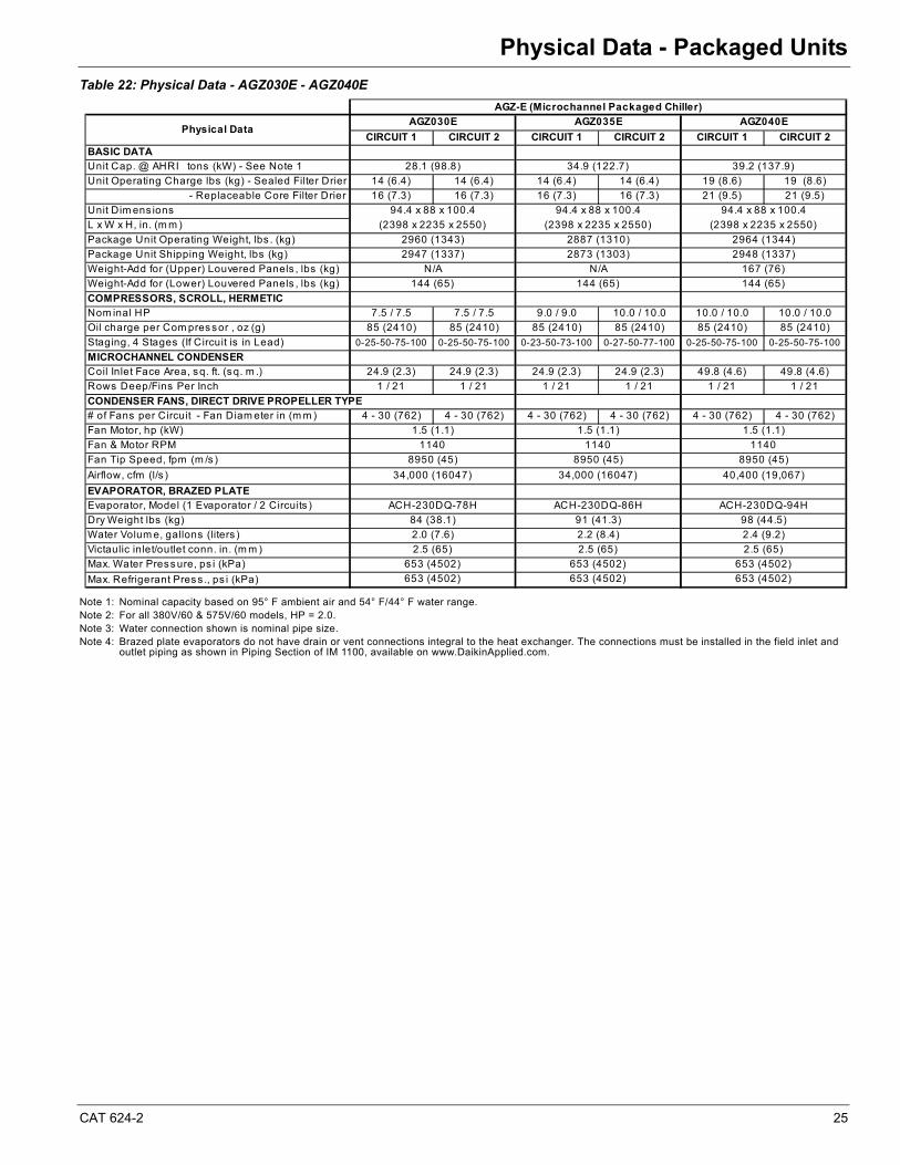
Physical Data - Packaged UnitsPhysical Data - Packaged Units
Table 22: Physical Data - AGZ030E - AGZ040E
Note 1: Nominal capacity based on 95° F ambient air and 54° F/44° F water range.Note 2: For all 380V/60 & 575V/60 models, HP = 2.0.Note 3: Water connection shown is nominal pipe size.Note 4: Brazed plate evaporators do not have drain or vent connections integral to the heat exchanger. The connections must be installed in the field inlet and
outlet piping as shown in Piping Section of IM 1100, available on www.DaikinApplied.com.
CIRCUIT 1 CIRCUIT 2 CIRCUIT 1 CIRCUIT 2 CIRCUIT 1 CIRCUIT 2
BASIC DATAUnit Cap. @ AHRI tons (kW) - See Note 1
Unit Operating Charge lbs (kg) - Sealed Filter Drier 14 (6.4) 14 (6.4) 14 (6.4) 14 (6.4) 19 (8.6) 19 (8.6)
- Replaceable Core Filter Drier 16 (7.3) 16 (7.3) 16 (7.3) 16 (7.3) 21 (9.5) 21 (9.5)
Unit Dim ens ions
L x W x H, in. (m m )
Package Unit Operating Weight, lbs . (kg)
Package Unit Shipping Weight, lbs (kg)
Weight-Add for (Upper) Louvered Panels , lbs (kg)
Weight-Add for (Lower) Louvered Panels , lbs (kg)
COMPRESSORS, SCROLL, HERMETICNom inal HP 7.5 / 7.5 7.5 / 7.5 9.0 / 9.0 10.0 / 10.0 10.0 / 10.0 10.0 / 10.0
Oil charge per Com pres sor , oz (g) 85 (2410) 85 (2410) 85 (2410) 85 (2410) 85 (2410) 85 (2410)
Staging, 4 Stages (If Circuit is in Lead) 0-25-50-75-100 0-25-50-75-100 0-23-50-73-100 0-27-50-77-100 0-25-50-75-100 0-25-50-75-100
MICROCHANNEL CONDENSERCoil Inlet Face Area, sq. ft. (sq. m .) 24.9 (2.3) 24.9 (2.3) 24.9 (2.3) 24.9 (2.3) 49.8 (4.6) 49.8 (4.6)
Rows Deep/Fins Per Inch 1 / 21 1 / 21 1 / 21 1 / 21 1 / 21 1 / 21
CONDENSER FANS, DIRECT DRIVE PROPELLER TYPE# of Fans per Circuit - Fan Diam eter in (m m ) 4 - 30 (762) 4 - 30 (762) 4 - 30 (762) 4 - 30 (762) 4 - 30 (762) 4 - 30 (762)
Fan Motor, hp (kW)
Fan & Motor RPM
Fan Tip Speed, fpm (m /s )
Airflow, cfm (l/s )
EVAPORATOR, BRAZED PLATEEvaporator, Model (1 Evaporator / 2 Circuits )
Dry Weight lbs (kg)
Water Volum e, gallons (liters )
Victaulic inlet/outlet conn. in. (m m )
Max. Water Press ure, ps i (kPa)
Max. Refrigerant Pres s ., ps i (kPa) 653 (4502)
1140 1140 1140
8950 (45)
ACH-230DQ-94H
34,000 (16047) 34,000 (16047) 40,400 (19,067)
8950 (45) 8950 (45)
(2398 x 2235 x 2550) (2398 x 2235 x 2550) (2398 x 2235 x 2550)
AGZ030E AGZ035E AGZ040E
2.4 (9.2)
94.4 x 88 x 100.4
98 (44.5)
144 (65)
84 (38.1) 91 (41.3)
ACH-230DQ-78H ACH-230DQ-86H
2.2 (8.4)
653 (4502)
2.5 (65) 2.5 (65) 2.5 (65)
653 (4502) 653 (4502) 653 (4502)
653 (4502)
1.5 (1.1) 1.5 (1.1) 1.5 (1.1)
2.0 (7.6)
2960 (1343) 2887 (1310) 2964 (1344)
144 (65) 144 (65)
N/A N/A 167 (76)
2947 (1337) 2873 (1303) 2948 (1337)
28.1 (98.8) 34.9 (122.7) 39.2 (137.9)
94.4 x 88 x 100.4
Physical Data
AGZ-E (Microchannel Packaged Chiller)
94.4 x 88 x 100.4
26 CAT 624-2
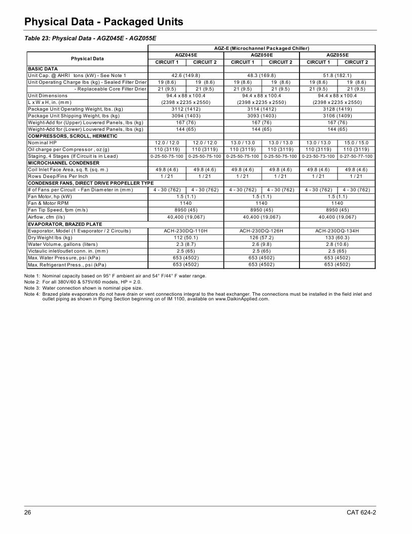
Physical Data - Packaged Units
Table 23: Physical Data - AGZ045E - AGZ055E
Note 1: Nominal capacity based on 95° F ambient air and 54° F/44° F water range.Note 2: For all 380V/60 & 575V/60 models, HP = 2.0.Note 3: Water connection shown is nominal pipe size. Note 4: Brazed plate evaporators do not have drain or vent connections integral to the heat exchanger. The connections must be installed in the field inlet and
outlet piping as shown in Piping Section beginning on of IM 1100, available on www.DaikinApplied.com.
CIRCUIT 1 CIRCUIT 2 CIRCUIT 1 CIRCUIT 2 CIRCUIT 1 CIRCUIT 2
BASIC DATAUnit Cap. @ AHRI tons (kW) - See Note 1
Unit Operating Charge lbs (kg) - Sealed Filter Drier 19 (8.6) 19 (8.6) 19 (8.6) 19 (8.6) 19 (8.6) 19 (8.6)
- Replaceable Core Filter Drier 21 (9.5) 21 (9.5) 21 (9.5) 21 (9.5) 21 (9.5) 21 (9.5)
Unit Dim ens ions
L x W x H, in. (m m )
Package Unit Operating Weight, lbs . (kg)
Package Unit Shipping Weight, lbs (kg)
Weight-Add for (Upper) Louvered Panels , lbs (kg)
Weight-Add for (Lower) Louvered Panels , lbs (kg)
COMPRESSORS, SCROLL, HERMETICNom inal HP 12.0 / 12.0 12.0 / 12.0 13.0 / 13.0 13.0 / 13.0 13.0 / 13.0 15.0 / 15.0
Oil charge per Com pres sor , oz (g) 110 (3119) 110 (3119) 110 (3119) 110 (3119) 110 (3119) 110 (3119)
Staging, 4 Stages (If Circuit is in Lead) 0-25-50-75-100 0-25-50-75-100 0-25-50-75-100 0-25-50-75-100 0-23-50-73-100 0-27-50-77-100
MICROCHANNEL CONDENSERCoil Inlet Face Area, sq. ft. (sq. m .) 49.8 (4.6) 49.8 (4.6) 49.8 (4.6) 49.8 (4.6) 49.8 (4.6) 49.8 (4.6)
Rows Deep/Fins Per Inch 1 / 21 1 / 21 1 / 21 1 / 21 1 / 21 1 / 21
CONDENSER FANS, DIRECT DRIVE PROPELLER TYPE# of Fans per Circuit - Fan Diam eter in (m m ) 4 - 30 (762) 4 - 30 (762) 4 - 30 (762) 4 - 30 (762) 4 - 30 (762) 4 - 30 (762)
Fan Motor, hp (kW)
Fan & Motor RPM
Fan Tip Speed, fpm (m /s )
Airflow, cfm (l/s )
EVAPORATOR, BRAZED PLATEEvaporator, Model (1 Evaporator / 2 Circuits )
Dry Weight lbs (kg)
Water Volum e, gallons (liters )
Victaulic inlet/outlet conn. in. (m m )
Max. Water Press ure, ps i (kPa)
Max. Refrigerant Pres s ., ps i (kPa)
AGZ045E AGZ050E
42.6 (149.8) 48.3 (169.8)
94.4 x 88 x 100.4 94.4 x 88 x 100.4
Physical Data
AGZ-E (Microchannel Packaged Chiller)
(2398 x 2235 x 2550) (2398 x 2235 x 2550)
3112 (1412) 3114 (1412)
3094 (1403) 3093 (1403)
167 (76) 167 (76)
144 (65) 144 (65)
1.5 (1.1) 1.5 (1.1)
1140 1140
8950 (45) 8950 (45)
40,400 (19,067) 40,400 (19,067)
ACH-230DQ-110H ACH-230DQ-126H
112 (50.1) 126 (57.2)
2.3 (8.7) 2.6 (9.8)
2.5 (65) 2.5 (65)
653 (4502) 653 (4502)
653 (4502) 653 (4502)
AGZ055E
51.8 (182.1)
94.4 x 88 x 100.4
(2398 x 2235 x 2550)
3128 (1419)
3106 (1409)
167 (76)
144 (65)
1.5 (1.1)
1140
8950 (45)
40,400 (19,067)
ACH-230DQ-134H
133 (60.3)
2.8 (10.6)
2.5 (65)
653 (4502)
653 (4502)

CAT 624-2 27
Physical Data - Packaged Units
Table 24: Physical Data - AGZ060E - AGZ070E
Note 1: Nominal capacity based on 95° F ambient air and 54° F/44° F water range.Note 2: For all 380V/60 & 575V/60 models, HP = 2.0.Note 3: Water connection shown is nominal pipe size. Note 4: Brazed plate evaporators do not have drain or vent connections integral to the heat exchanger. The connections must be installed in the field inlet and
outlet piping as shown in Piping Section beginning on of IM 1100, available on www.DaikinApplied.com.
CIRCUIT 1 CIRCUIT 2 CIRCUIT 1 CIRCUIT 2 CIRCUIT 1 CIRCUIT 2
BASIC DATAUnit Cap. @ AHRI tons (kW) - See Note 1
Unit Operating Charge lbs (kg) - Sealed Filter Drier 19 (8.6) 19 (8.6) 19 (8.6) 19 (8.6) 20 (9.1) 20 (9.1)
- Replaceable Core Filter Drier 21 (9.5) 21 (9.5) 21 (9.5) 21 (9.5) 22 (10.0) 22 (10.0)
Unit Dim ens ions
L x W x H, in. (m m )
Package Unit Operating Weight, lbs . (kg)
Package Unit Shipping Weight, lbs (kg)
Weight-Add for (Upper) Louvered Panels , lbs (kg)
Weight-Add for (Lower) Louvered Panels , lbs (kg)
COMPRESSORS, SCROLL, HERMETICNom inal HP 15.0 / 15.0 15.0 / 15.0 15.0 / 15.0 15.0 / 15.0 15.0 / 20.0 15.0 / 20.0
Oil charge per Com pressor , oz (g) 110 (3119) 110 (3119) 110 (3119) 110 (3119)110 (3119) 152 (4309)
110 (3119) 152 (4309)
Staging, 4 Stages (If Circuit is in Lead) 0-25-50-75-100 0-25-50-75-100 0-25-50-75-100 0-25-50-75-100 0-21-50-71-100 0-28-50-78-100
MICROCHANNEL CONDENSERCoil Inlet Face Area, sq. ft. (sq. m .) 49.8 (4.6) 49.8 (4.6) 49.8 (4.6) 49.8 (4.6) 49.8 (4.6) 49.8 (4.6)
Rows Deep/Fins Per Inch 1 / 21 1 / 21 1 / 21 1 / 21 1 / 21 1 / 21
CONDENSER FANS, DIRECT DRIVE PROPELLER TYPE# of Fans per Circuit - Fan Diam eter in (m m ) 4 - 30 (762) 4 - 30 (762) 4 - 30 (762) 4 - 30 (762) 4 - 30 (762) 4 - 30 (762)
Fan Motor, hp (kW)
Fan & Motor RPM
Fan Tip Speed, fpm (m /s )
Airflow, cfm (l/s )
EVAPORATOR, BRAZED PLATEEvaporator, Model (1 Evaporator / 2 Circuits )
Dry Weight lbs (kg)
Water Volum e, gallons (liters )
Victaulic inlet/outlet conn. in. (m m )
Max. Water Pressure, ps i (kPa)
Max. Refrigerant Press ., ps i (kPa)
653 (4502)
2.5 (65) 2.5 (65)
Physical Data
150 (68.1)
653 (4502) 653 (4502)
653 (4502) 653 (4502) 653 (4502)
2.8 (10.6) 2.8 (10.6) 2.8 (10.6)
40,400 (19,067) 48,000 (22654) 48,000 (22654)
2.5 (65)
ACH-230DQ-154H ACH-230DQ-154H ACH-230DQ-154H
150 (68.1) 150 (68.1)
1.5 (1.1) 2.0 (1.5) 2.0 (1.5)
1140 1140 1140
8950 (45) 8950 (45) 8950 (45)
144 (65) 144 (65) 144 (65)
3155 (1431)
AGZ060E AGZ065E AGZ070E
57.0 (200.5) 58.7 (206.4) 65.1 (228.9)
94.4 x 88 x 100.4
3497 (1586)
167 (76) 167 (76) 167 (76)
(2398 x 2235 x 2550) (2398 x 2235 x 2550)
3155 (1431)
94.4 x 88 x 100.4
3130 (1420) 3130 (1420) 3472 (1575)
AGZ-E (Microchannel Packaged Chiller)
94.4 x 88 x 100.4
(2398 x 2235 x 2550)
28 CAT 624-2
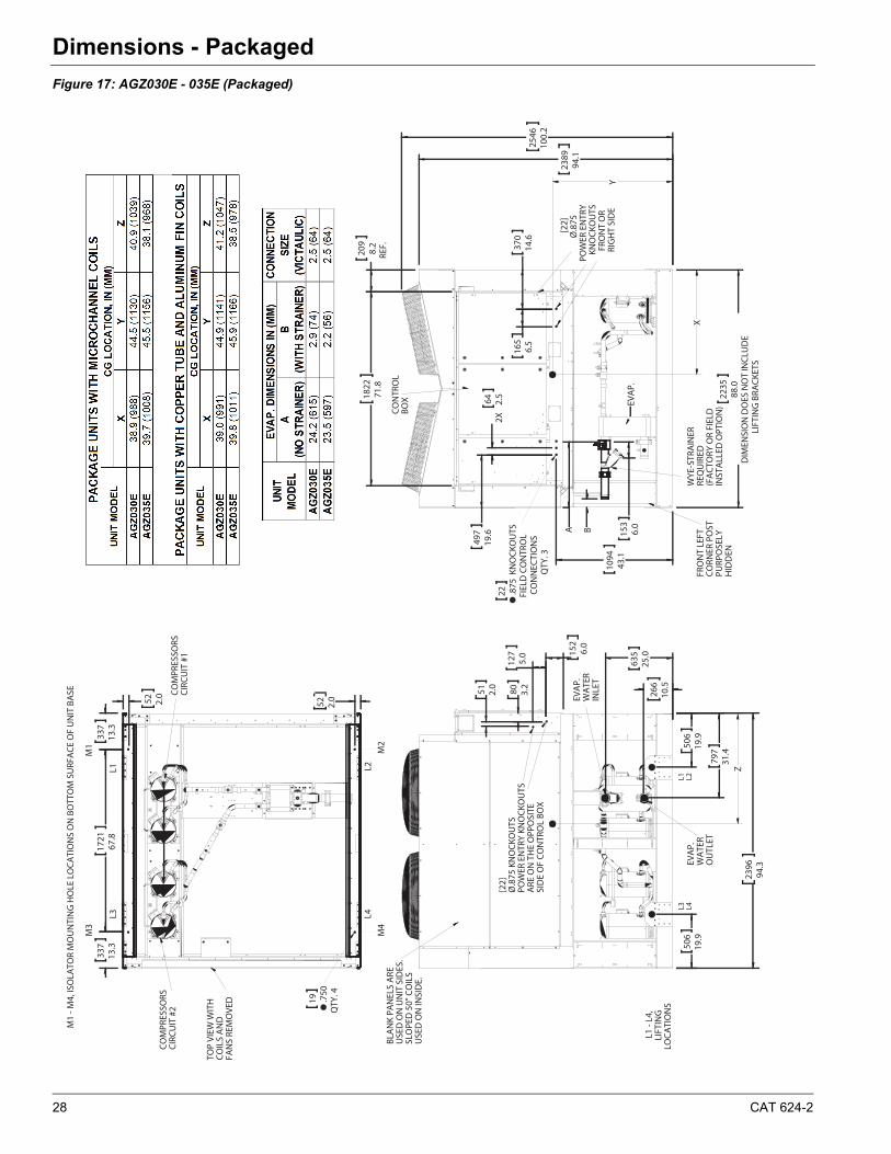
Dimensions - PackagedDimensions - Packaged
Figure 17: AGZ030E - 035E (Packaged)
1822
71.8
209
8.2
REF.
2389
94.1
2546
100.
2
165
6.5
370
14.6
2X
64 2.5
497
19.6
1094
43.1
22 .875
KN
OCK
OU
TSFI
ELD
CO
NTR
OL
CON
NEC
TIO
NS
QTY
. 3
2235
88.0
DIM
ENSI
ON
DO
ES N
OT
INCL
UD
ELI
FTIN
G B
RACK
ETS
B 153
6.0A
X
Y
CON
TRO
LBO
X
FRO
NT
LEFT
CO
RNER
PO
ST
PURP
OSE
LY
HID
DEN
EVA
P.
WYE
-STR
AIN
ER
REQ
UIR
ED(F
ACT
ORY
OR
FIEL
D
INST
ALL
ED O
PTIO
N)
[22]
Ø.8
75PO
WER
EN
TRY
KNO
CKO
UTS
FRO
NT
OR
RIG
HT
SID
E
635
25.0
266
10.5
797
31.4
506
19.9
2396
94.3
506
19.9
51 2.0 80 3.2
152
6.0
127
5.0
Z
BLA
NK
PAN
ELS
ARE
USE
D O
N U
NIT
SID
ES.
SLO
PED
50"
CO
ILS
USE
D O
N IN
SID
E.
[22]
Ø.8
75 K
NO
CKO
UTS
POW
ER E
NTR
Y KN
OCK
OU
TSA
RE O
N T
HE
OPP
OSI
TESI
DE
OF
CON
TRO
L BO
X
EVA
P.W
ATE
RIN
LET
EVA
P.W
ATE
RO
UTL
ET
L1 L2L3 L4
337
13.3
1721
67.8
337
13.3
52 2.0
52 2.0
19 .750
QTY
. 4
M1
- M4,
ISO
LATO
R M
OU
NTI
NG
HO
LE L
OCA
TIO
NS
ON
BO
TTO
M S
URF
ACE
OF
UN
IT B
ASE
M3
M1 M2
M4
L4L2L1
L3
COM
PRES
SORS
CIRC
UIT
#2
COM
PRES
SORS
CIRC
UIT
#1
L1 -
L4,
LIFT
ING
LOCA
TIO
NS
TOP
VIEW
WIT
H
COIL
S A
ND
FA
NS
REM
OVE
D
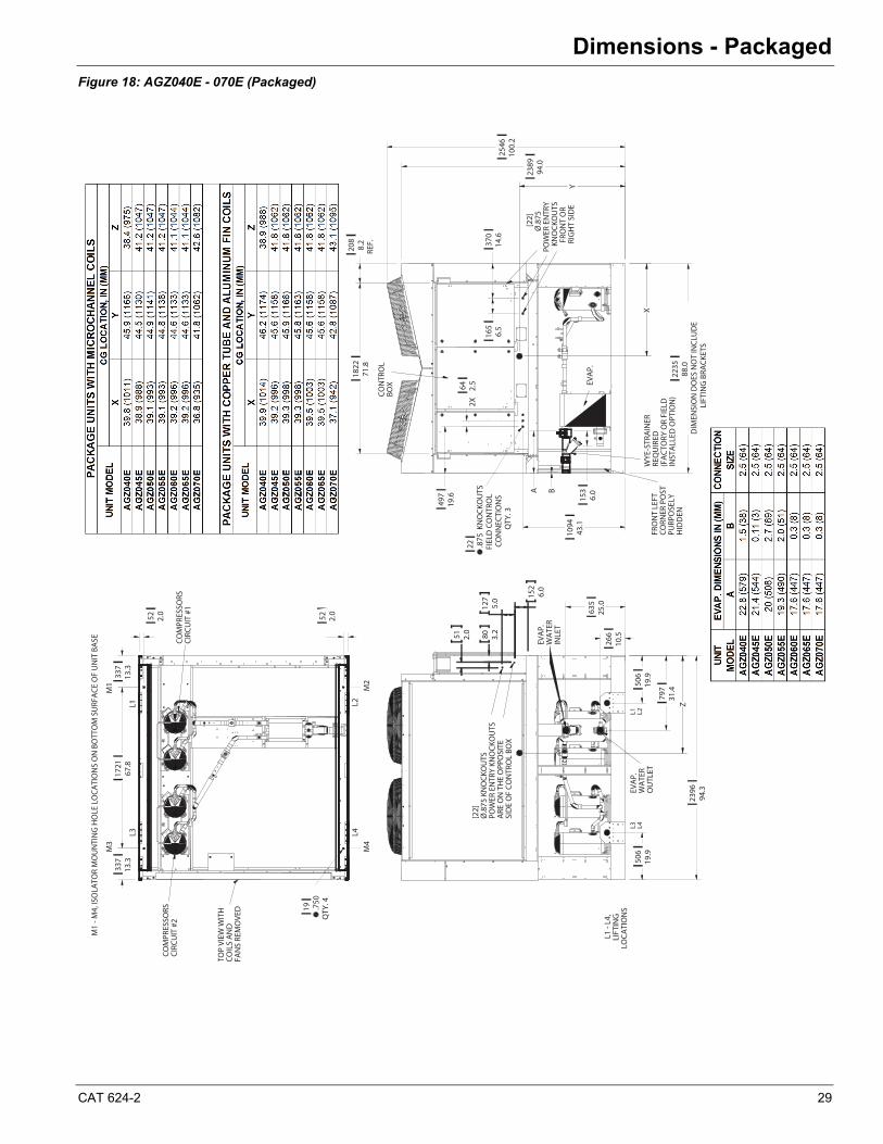
CAT 624-2 29
Dimensions - Packaged
Figure 18: AGZ040E - 070E (Packaged)
1822
71.8
208
8.2
REF.
2389
94.0
2546
100.
2
165
6.5
370
14.6
2X
64 2.5
497
19.6
1094
43.1
22 .875
KN
OCK
OU
TSFI
ELD
CO
NTR
OL
CON
NEC
TIO
NS
QTY
. 3
2235
88.0
DIM
ENSI
ON
DO
ES N
OT
INCL
UD
ELI
FTIN
G B
RACK
ETS
B
153
6.0A
X
Y
CON
TRO
LBO
X
FRO
NT
LEFT
CO
RNER
PO
ST
PURP
OSE
LY
HID
DEN
EVA
P.
WYE
-STR
AIN
ER
REQ
UIR
ED(F
ACT
ORY
OR
FIEL
D
INST
ALL
ED O
PTIO
N)
[22]
Ø.8
75PO
WER
EN
TRY
KNO
CKO
UTS
FRO
NT
OR
RIG
HT
SID
E
635
25.0
266
10.5
797
31.4
506
19.9
2396
94.3
506
19.9
51 2.0 80 3.2
152
6.0
127
5.0
Z
[22]
Ø.8
75 K
NO
CKO
UTS
POW
ER E
NTR
Y KN
OCK
OU
TSA
RE O
N T
HE
OPP
OSI
TESI
DE
OF
CON
TRO
L BO
X
EVA
P.W
ATE
RIN
LET
EVA
P.W
ATE
RO
UTL
ET
L1 L2L3 L4
L1 -
L4,
LIFT
ING
LOCA
TIO
NS
337
13.3
1721
67.8
337
13.3
52 2.0 52 2.0
19 .750
QTY
. 4
M1
- M4,
ISO
LATO
R M
OU
NTI
NG
HO
LE L
OCA
TIO
NS
ON
BO
TTO
M S
URF
ACE
OF
UN
IT B
ASE
M3
M1 M2
M4
L4L2L1
L3
COM
PRES
SORS
CIRC
UIT
#2
COM
PRES
SORS
CIRC
UIT
#1
TOP
VIEW
WIT
H
COIL
S A
ND
FA
NS
REM
OVE
D
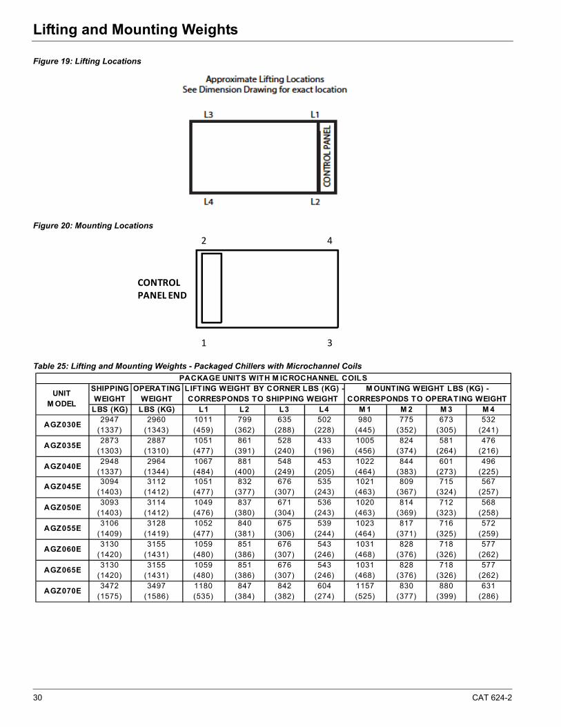
30 CAT 624-2
Lifting and Mounting WeightsLifting and Mounting Weights
Figure 19: Lifting Locations
Figure 20: Mounting Locations
Table 25: Lifting and Mounting Weights - Packaged Chillers with Microchannel Coils
2
1
4
3
CONTROLPANEL END
SHIPPING WEIGHT
OPERATING WEIGHT
LBS (KG) LBS (KG) L1 L2 L3 L4 M 1 M 2 M 3 M 4
AGZ030E2947
(1337)2960
(1343)1011 (459)
799 (362)
635 (288)
502 (228)
980 (445)
775 (352)
673 (305)
532 (241)
AGZ035E2873
(1303)2887
(1310)1051 (477)
861 (391)
528 (240)
433 (196)
1005 (456)
824 (374)
581 (264)
476 (216)
AGZ040E2948
(1337)2964
(1344)1067 (484)
881 (400)
548 (249)
453 (205)
1022 (464)
844 (383)
601 (273)
496 (225)
AGZ045E3094
(1403)3112
(1412)1051 (477)
832 (377)
676 (307)
535 (243)
1021 (463)
809 (367)
715 (324)
567 (257)
AGZ050E3093
(1403)3114
(1412)1049 (476)
837 (380)
671 (304)
536 (243)
1020 (463)
814 (369)
712 (323)
568 (258)
AGZ055E3106
(1409)3128
(1419)1052 (477)
840 (381)
675 (306)
539 (244)
1023 (464)
817 (371)
716 (325)
572 (259)
AGZ060E3130
(1420)3155
(1431)1059 (480)
851 (386)
676 (307)
543 (246)
1031 (468)
828 (376)
718 (326)
577 (262)
AGZ065E3130
(1420)3155
(1431)1059 (480)
851 (386)
676 (307)
543 (246)
1031 (468)
828 (376)
718 (326)
577 (262)
AGZ070E3472
(1575)3497
(1586)1180 (535)
847 (384)
842 (382)
604 (274)
1157 (525)
830 (377)
880 (399)
631 (286)
PACKAGE UNITS WITH M ICROCHANNEL COILS
UNIT M ODEL
LIFTING WEIGHT BY CORNER LBS (KG) -CORRESPONDS TO SHIPPING WEIGHT
M OUNTING WEIGHT LBS (KG) - CORRESPONDS TO OPERATING WEIGHT
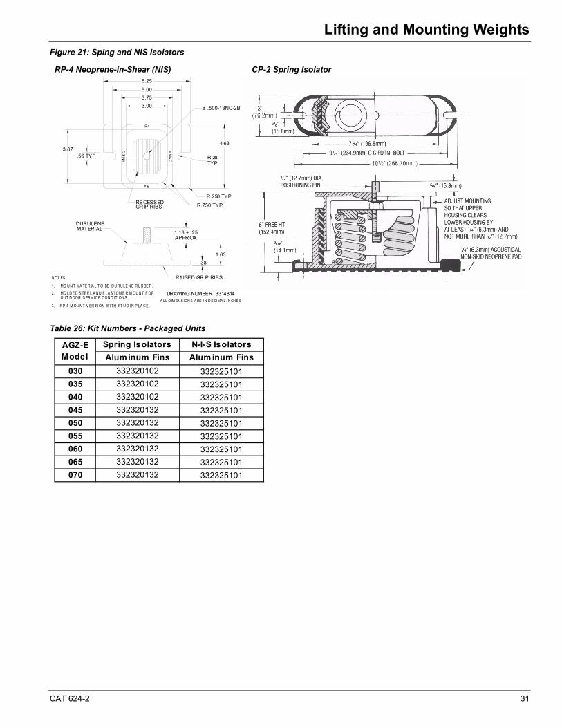
CAT 624-2 31
Lifting and Mounting Weights
Figure 21: Sping and NIS Isolators
Table 26: Kit Numbers - Packaged Units
N OT ES :
MO U N T MA TE R IA L T O BE D U R U LE N E R U B BE R .1.
MO LD E D S TE E L A N D E LA S TOM E R M OU N T F OR2.OU T D OOR S ER V I C E C ON D I TI ON S .
3. R P -4 M OU N T V ER SI ON W I TH ST U D I N P LA C E .A LL D IM EN S ION S A RE I N D E CI MA L I N CH E S
DRAWING NUMBER 3314814
1.13 ± .25APPR OX.
1.63
.38
DURULENEMATERIAL
RAISED GR IP RIBS
3.00
3.75
5.00
6.25
3.87.56 TYP.
4.63
R.28TYP.
R.250 TYP.
R.750 TYP.RECESSEDGR IP RIBS
ø .500-13NC-2B
R 4
R4
VM
&C
VM
&C
RP-4 Neoprene-in-Shear (NIS) CP-2 Spring Isolator
Spring Isolators N-I-S Isolators
Aluminum Fins Alum inum Fins
030 332320102 332325101
035 332320102 332325101
040 332320102 332325101
045 332320132 332325101
050 332320132 332325101
055 332320132 332325101
060 332320132 332325101
065 332320132 332325101
070 332320132 332325101
AGZ-E Model
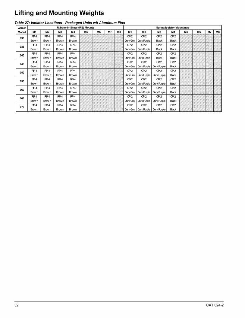
32 CAT 624-2
Lifting and Mounting Weights
Table 27: Isolator Locations - Packaged Units wit Aluminum Fins
M1 M2 M3 M4 M5 M6 M7 M8 M1 M2 M3 M4 M5 M6 M7 M8
RP-4 RP-4 RP-4 RP-4 CP-2 CP-2 CP-2 CP-2
Brown Brown Brown Brown Dark Grn Dark Purple Black Black
RP-4 RP-4 RP-4 RP-4 CP-2 CP-2 CP-2 CP-2
Brown Brown Brown Brown Dark Grn Dark Purple Black Black
RP-4 RP-4 RP-4 RP-4 CP-2 CP-2 CP-2 CP-2
Brown Brown Brown Brown Dark Grn Dark Purple Black Black
RP-4 RP-4 RP-4 RP-4 CP-2 CP-2 CP-2 CP-2
Brown Brown Brown Brown Dark Grn Dark Purple Dark Purple Black
RP-4 RP-4 RP-4 RP-4 CP-2 CP-2 CP-2 CP-2
Brown Brown Brown Brown Dark Grn Dark Purple Dark Purple Black
RP-4 RP-4 RP-4 RP-4 CP-2 CP-2 CP-2 CP-2
Brown Brown Brown Brown Dark Grn Dark Purple Dark Purple Black
RP-4 RP-4 RP-4 RP-4 CP-2 CP-2 CP-2 CP-2
Brown Brown Brown Brown Dark Grn Dark Purple Dark Purple Black
RP-4 RP-4 RP-4 RP-4 CP-2 CP-2 CP-2 CP-2
Brown Brown Brown Brown Dark Grn Dark Purple Dark Purple Black
RP-4 RP-4 RP-4 RP-4 CP-2 CP-2 CP-2 CP-2
Brown Brown Brown Brown Dark Grn Dark Purple Dark Purple Black
Rubber-In-Shear (RIS) Mounts Spring Isolator Mountings
035
040
045
050
030
AGZ-EModel
055
060
065
070
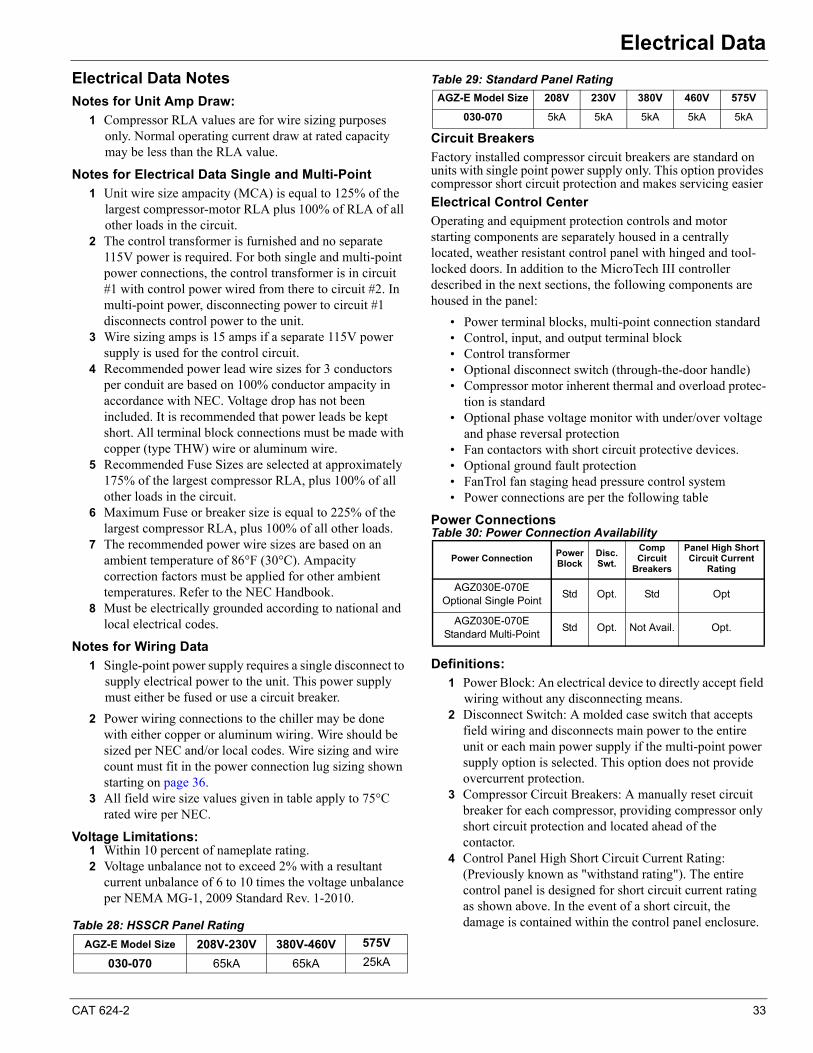
CAT 624-2 33
Electrical DataElectrical Data
Electrical Data NotesNotes for Unit Amp Draw:
1 Compressor RLA values are for wire sizing purposes only. Normal operating current draw at rated capacity may be less than the RLA value.
Notes for Electrical Data Single and Multi-Point
1 Unit wire size ampacity (MCA) is equal to 125% of the largest compressor-motor RLA plus 100% of RLA of all other loads in the circuit.
2 The control transformer is furnished and no separate 115V power is required. For both single and multi-point power connections, the control transformer is in circuit #1 with control power wired from there to circuit #2. In multi-point power, disconnecting power to circuit #1 disconnects control power to the unit.
3 Wire sizing amps is 15 amps if a separate 115V power supply is used for the control circuit.
4 Recommended power lead wire sizes for 3 conductors per conduit are based on 100% conductor ampacity in accordance with NEC. Voltage drop has not been included. It is recommended that power leads be kept short. All terminal block connections must be made with copper (type THW) wire or aluminum wire.
5 Recommended Fuse Sizes are selected at approximately 175% of the largest compressor RLA, plus 100% of all other loads in the circuit.
6 Maximum Fuse or breaker size is equal to 225% of the largest compressor RLA, plus 100% of all other loads.
7 The recommended power wire sizes are based on an ambient temperature of 86°F (30°C). Ampacity correction factors must be applied for other ambient temperatures. Refer to the NEC Handbook.
8 Must be electrically grounded according to national and local electrical codes.
Notes for Wiring Data
1 Single-point power supply requires a single disconnect to supply electrical power to the unit. This power supply must either be fused or use a circuit breaker.
2 Power wiring connections to the chiller may be done with either copper or aluminum wiring. Wire should be sized per NEC and/or local codes. Wire sizing and wire count must fit in the power connection lug sizing shown starting on page 36.
3 All field wire size values given in table apply to 75°C rated wire per NEC.
Voltage Limitations:1 Within 10 percent of nameplate rating.2 Voltage unbalance not to exceed 2% with a resultant
current unbalance of 6 to 10 times the voltage unbalance per NEMA MG-1, 2009 Standard Rev. 1-2010.
Table 28: HSSCR Panel Rating
Table 29: Standard Panel Rating
Circuit Breakers
Factory installed compressor circuit breakers are standard on units with single point power supply only. This option provides compressor short circuit protection and makes servicing easier
Electrical Control Center
Operating and equipment protection controls and motor starting components are separately housed in a centrally located, weather resistant control panel with hinged and tool-locked doors. In addition to the MicroTech III controller described in the next sections, the following components are housed in the panel:
• Power terminal blocks, multi-point connection standard• Control, input, and output terminal block• Control transformer• Optional disconnect switch (through-the-door handle)• Compressor motor inherent thermal and overload protec-
tion is standard • Optional phase voltage monitor with under/over voltage
and phase reversal protection• Fan contactors with short circuit protective devices.• Optional ground fault protection• FanTrol fan staging head pressure control system• Power connections are per the following table
Power ConnectionsTable 30: Power Connection Availability
Definitions:
1 Power Block: An electrical device to directly accept field wiring without any disconnecting means.
2 Disconnect Switch: A molded case switch that accepts field wiring and disconnects main power to the entire unit or each main power supply if the multi-point power supply option is selected. This option does not provide overcurrent protection.
3 Compressor Circuit Breakers: A manually reset circuit breaker for each compressor, providing compressor only short circuit protection and located ahead of the contactor.
4 Control Panel High Short Circuit Current Rating: (Previously known as "withstand rating"). The entire control panel is designed for short circuit current rating as shown above. In the event of a short circuit, the damage is contained within the control panel enclosure.
AGZ-E Model Size 208V-230V 380V-460V 575V
030-070 65kA 65kA 25kA
AGZ-E Model Size 208V 230V 380V 460V 575V
030-070 5kA 5kA 5kA 5kA 5kA
Power ConnectionPower Block
Disc. Swt.
Comp Circuit
Breakers
Panel High Short Circuit Current
Rating
AGZ030E-070EOptional Single Point
Std Opt. Std Opt
AGZ030E-070EStandard Multi-Point
Std Opt. Not Avail. Opt.
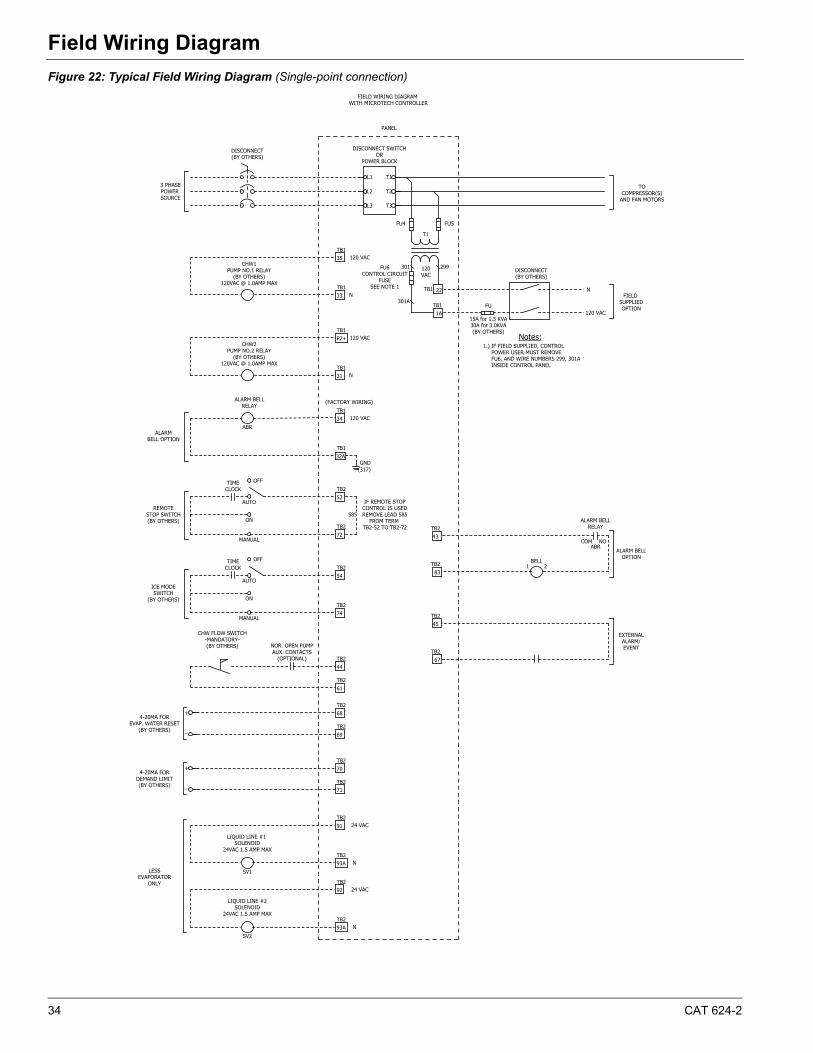
34 CAT 624-2
Field Wiring DiagramField Wiring Diagram
Figure 22: Typical Field Wiring Diagram (Single-point connection)
NOCOM
BELL
LESSEVAPORATOR
ONLY
N
24 VAC
N
24 VAC
LIQUID LINE #2SOLENOID
24VAC 1.5 AMP MAX
LIQUID LINE #1 SOLENOID
24VAC 1.5 AMP MAX
4-20MA FORDEMAND LIMIT(BY OTHERS)
4-20MA FOREVAP. WATER RESET
(BY OTHERS)
CHW FLOW SWITCH-MANDATORY-(BY OTHERS) NOR. OPEN PUMP
AUX. CONTACTS(OPTIONAL)
ICE MODESWITCH
(BY OTHERS)
TIMECLOCK
OFF
MANUAL
ON
AUTO
585
IF REMOTE STOPCONTROL IS USEDREMOVE LEAD 585
FROM TERM TB2-52 TO TB2-72
TIMECLOCK
OFF
MANUAL
ON
AUTO
CHW2PUMP NO.2 RELAY
(BY OTHERS)120VAC @ 1.0AMP MAX
93ATB2
92TB2
93ATB2
91TB2
71TB2
70TB2
69TB2
68TB2
61TB2
TB1 22
TB11A
TOCOMPRESSOR(S)
AND FAN MOTORS
ALARM BELLRELAY
120VAC
FU5
T1
FU6CONTROL CIRCUIT
FUSESEE NOTE 1
FU4
REMOTESTOP SWITCH(BY OTHERS)
TB2
TB2
43
83
ALARM BELLOPTION
N
N
120 VAC
120 VAC
120 VAC
(FACTORY WIRING)
TB1
TB1
TB1
TB1
TB1
TB1
TB2
TB2
TB2
TB2
TB2
ALARM BELL�RELAY
44
54
52
34
P2+
CHW1PUMP NO.1 RELAY
(BY OTHERS)120VAC @ 1.0AMP MAX
35
74
72
32A
31
33
ALARMBELL OPTION
3 PHASEPOWER SOURCE
DISCONNECT SWITCHOR
POWER BLOCK
DISCONNECT(BY OTHERS)
1 2
TB2
TB2
45
67
EXTERNALALARM/EVENT
DISCONNECT(BY OTHERS)
N
120 VAC
FIELD SUPPLIEDOPTIONFU
15A for 1.5 KVA30A for 3.0KVA(BY OTHERS)
Notes:1.) IF FIELD SUPPLIED, CONTROL
POWER USER MUST REMOVE FU6, AND WIRE NUMBERS 299, 301A INSIDE CONTROL PANEL
FIELD WIRING DIAGRAM WITH MICROTECH CONTROLLER
301A
301 299
ABR
ABR
SV1
SV2
_
+
_
+
GND(317)
T3
T2
T1
L3
L2
L1
PANEL
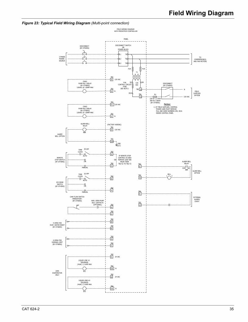
CAT 624-2 35
Field Wiring Diagram
Figure 23: Typical Field Wiring Diagram (Multi-point connection)
NOCOM
BELL
LESSEVAPORATOR
ONLY
N
24 VAC
N
24 VAC
LIQUID LINE #2SOLENOID
24VAC 1.5 AMP MAX
LIQUID LINE #1 SOLENOID
24VAC 1.5 AMP MAX
4-20MA FORDEMAND LIMIT(BY OTHERS)
4-20MA FOREVAP. WATER RESET
(BY OTHERS)
CHW FLOW SWITCH-MANDATORY-(BY OTHERS) NOR. OPEN PUMP
AUX. CONTACTS(OPTIONAL)
ICE MODESWITCH
(BY OTHERS)
TIMECLOCK
OFF
MANUAL
ON
AUTO
585
IF REMOTE STOPCONTROL IS USEDREMOVE LEAD 585
FROM TERM TB2-52 TO TB2-72
TIMECLOCK
OFF
MANUAL
ON
AUTO
CHW2PUMP NO.2 RELAY
(BY OTHERS)120VAC @ 1.0AMP MAX
93ATB2
92TB2
93ATB2
91TB2
71TB2
70TB2
69TB2
68TB2
61TB2
TB1 22
TB11A
TOCOMPRESSOR(S)
AND FAN MOTORS
ALARM BELLRELAY
120VAC
FU5
T1
FU6CONTROL CIRCUIT
FUSESEE NOTE 1
FU4
REMOTESTOP SWITCH(BY OTHERS)
TB2
TB2
43
83
ALARM BELLOPTION
N
N
120 VAC
120 VAC
120 VAC
(FACTORY WIRING)
TB1
TB1
TB1
TB1
TB1
TB1
TB2
TB2
TB2
TB2
TB2
ALARM BELL�RELAY
44
54
52
34
P2+
CHW1PUMP NO.1 RELAY
(BY OTHERS)120VAC @ 1.0AMP MAX
35
74
72
32A
31
33
ALARMBELL OPTION
3 PHASEPOWER SOURCE
DISCONNECT SWITCHOR
POWER BLOCK
DISCONNECT(BY OTHERS)
1 2
TB2
TB2
45
67
EXTERNALALARM/EVENT
DISCONNECT(BY OTHERS)
N
120 VAC
FIELD SUPPLIEDOPTIONFU
15A for 1.5 KVA30A for 3.0KVA(BY OTHERS)
Notes:1.) IF FIELD SUPPLIED, CONTROL
POWER USER MUST REMOVE FU6, AND WIRE NUMBERS 299, 301A INSIDE CONTROL PANEL
FIELD WIRING DIAGRAM WITH MICROTECH CONTROLLER
301A
301 299
ABR
ABR
SV1
SV2
_
+
_
+
GND(317)
T3
T2
T1
L3
L2
L1
PANEL
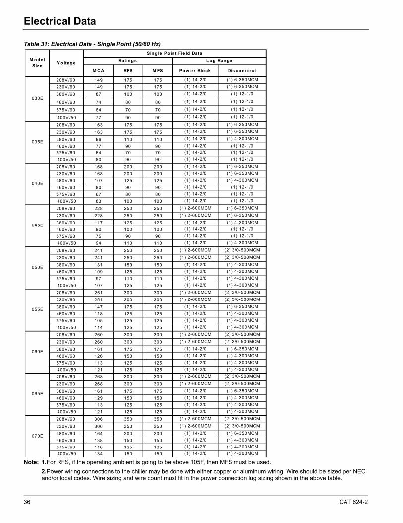
36 CAT 624-2
Electrical DataElectrical Data
Table 31: Electrical Data - Single Point (50/60 Hz)
Note: 1.For RFS, if the operating ambient is going to be above 105F, then MFS must be used.
2.Power wiring connections to the chiller may be done with either copper or aluminum wiring. Wire should be sized per NEC and/or local codes. Wire sizing and wire count must fit in the power connection lug sizing shown in the above table.
M CA RFS M FS Pow e r Block Dis conne ct
208V /60 149 175 175 (1) 14-2/0 (1) 6-350MCM
230V /60 149 175 175 (1) 14-2/0 (1) 6-350MCM
380V /60 87 100 100 (1) 14-2/0 (1) 12-1/0
460V /60 74 80 80 (1) 14-2/0 (1) 12-1/0
575V /60 64 70 70 (1) 14-2/0 (1) 12-1/0
400V /50 77 90 90 (1) 14-2/0 (1) 12-1/0
208V /60 163 175 175 (1) 14-2/0 (1) 6-350MCM
230V /60 163 175 175 (1) 14-2/0 (1) 6-350MCM
380V /60 96 110 110 (1) 14-2/0 (1) 4-300MCM
460V /60 77 90 90 (1) 14-2/0 (1) 12-1/0
575V /60 64 70 70 (1) 14-2/0 (1) 12-1/0
400V /50 80 90 90 (1) 14-2/0 (1) 12-1/0
208V /60 168 200 200 (1) 14-2/0 (1) 6-350MCM
230V /60 168 200 200 (1) 14-2/0 (1) 6-350MCM
380V /60 107 125 125 (1) 14-2/0 (1) 4-300MCM
460V /60 80 90 90 (1) 14-2/0 (1) 12-1/0
575V /60 67 80 80 (1) 14-2/0 (1) 12-1/0
400V /50 83 100 100 (1) 14-2/0 (1) 12-1/0
208V /60 228 250 250 (1) 2-600MCM (1) 6-350MCM
230V /60 228 250 250 (1) 2-600MCM (1) 6-350MCM
380V /60 117 125 125 (1) 14-2/0 (1) 4-300MCM
460V /60 90 100 100 (1) 14-2/0 (1) 12-1/0
575V /60 75 90 90 (1) 14-2/0 (1) 12-1/0
400V /50 94 110 110 (1) 14-2/0 (1) 4-300MCM
208V /60 241 250 250 (1) 2-600MCM (2) 3/0-500MCM
230V /60 241 250 250 (1) 2-600MCM (2) 3/0-500MCM
380V /60 131 150 150 (1) 14-2/0 (1) 4-300MCM
460V /60 109 125 125 (1) 14-2/0 (1) 4-300MCM
575V /60 97 110 110 (1) 14-2/0 (1) 4-300MCM
400V /50 107 125 125 (1) 14-2/0 (1) 4-300MCM
208V /60 251 300 300 (1) 2-600MCM (2) 3/0-500MCM
230V /60 251 300 300 (1) 2-600MCM (2) 3/0-500MCM
380V /60 147 175 175 (1) 14-2/0 (1) 6-350MCM
460V /60 118 125 125 (1) 14-2/0 (1) 4-300MCM
575V /60 105 125 125 (1) 14-2/0 (1) 4-300MCM
400V /50 114 125 125 (1) 14-2/0 (1) 4-300MCM
208V /60 260 300 300 (1) 2-600MCM (2) 3/0-500MCM
230V /60 260 300 300 (1) 2-600MCM (2) 3/0-500MCM
380V /60 161 175 175 (1) 14-2/0 (1) 6-350MCM
460V /60 126 150 150 (1) 14-2/0 (1) 4-300MCM
575V /60 113 125 125 (1) 14-2/0 (1) 4-300MCM
400V /50 121 125 125 (1) 14-2/0 (1) 4-300MCM
208V /60 268 300 300 (1) 2-600MCM (2) 3/0-500MCM
230V /60 268 300 300 (1) 2-600MCM (2) 3/0-500MCM
380V /60 161 175 175 (1) 14-2/0 (1) 6-350MCM
460V /60 129 150 150 (1) 14-2/0 (1) 4-300MCM
575V /60 113 125 125 (1) 14-2/0 (1) 4-300MCM
400V /50 121 125 125 (1) 14-2/0 (1) 4-300MCM
208V /60 306 350 350 (1) 2-600MCM (2) 3/0-500MCM
230V /60 306 350 350 (1) 2-600MCM (2) 3/0-500MCM
380V /60 164 200 200 (1) 14-2/0 (1) 6-350MCM
460V /60 138 150 150 (1) 14-2/0 (1) 4-300MCM
575V /60 116 125 125 (1) 14-2/0 (1) 4-300MCM
400V /50 134 150 150 (1) 14-2/0 (1) 4-300MCM
Ratings
030E
M ode l Size
V oltage Lug Range
Single Point Fie ld Data
070E
035E
040E
045E
050E
055E
060E
065E
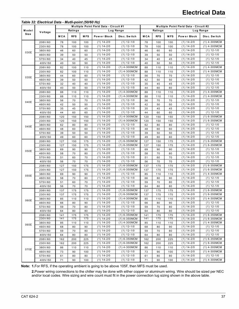
CAT 624-2 37
Electrical Data
Table 32: Electrical Data - Mutli-point (50/60 Hz)
Note: 1.For RFS, if the operating ambient is going to be above 105F, then MFS must be used.
2.Power wiring connections to the chiller may be done with either copper or aluminum wiring. Wire should be sized per NEC and/or local codes. Wire sizing and wire count must fit in the power connection lug sizing shown in the above table.
M CA RFS M FS Pow e r Block Dis c. Sw itch M CA RFS M FS Pow e r Block Dis c. Sw itch
208V /60 78 100 100 (1) 14-2/0 (1) 12-1/0 78 100 100 (1) 14-2/0 (1) 4-300MCM
230V /60 78 100 100 (1) 14-2/0 (1) 12-1/0 78 100 100 (1) 14-2/0 (1) 4-300MCM
380V /60 46 60 60 (1) 14-2/0 (1) 12-1/0 46 60 60 (1) 14-2/0 (1) 12-1/0
460V /60 39 50 50 (1) 14-2/0 (1) 12-1/0 39 50 50 (1) 14-2/0 (1) 12-1/0
575V /60 34 40 45 (1) 14-2/0 (1) 12-1/0 34 40 45 (1) 14-2/0 (1) 12-1/0
400V /50 40 50 50 (1) 14-2/0 (1) 12-1/0 40 50 50 (1) 14-2/0 (1) 12-1/0
208V /60 82 100 110 (1) 14-2/0 (1) 4-300MCM 88 110 110 (1) 14-2/0 (1) 4-300MCM
230V /60 82 100 110 (1) 14-2/0 (1) 4-300MCM 88 110 110 (1) 14-2/0 (1) 4-300MCM
380V /60 44 60 60 (1) 14-2/0 (1) 12-1/0 56 70 70 (1) 14-2/0 (1) 12-1/0
460V /60 39 50 50 (1) 14-2/0 (1) 12-1/0 42 50 50 (1) 14-2/0 (1) 12-1/0
575V /60 32 40 40 (1) 14-2/0 (1) 12-1/0 35 45 45 (1) 14-2/0 (1) 12-1/0
400V /50 40 50 50 (1) 14-2/0 (1) 12-1/0 44 60 60 (1) 14-2/0 (1) 12-1/0
208V /60 88 110 110 (1) 14-2/0 (1) 4-300MCM 88 110 110 (1) 14-2/0 (1) 4-300MCM
230V /60 88 110 110 (1) 14-2/0 (1) 4-300MCM 88 110 110 (1) 14-2/0 (1) 4-300MCM
380V /60 56 70 70 (1) 14-2/0 (1) 12-1/0 56 70 70 (1) 14-2/0 (1) 12-1/0
460V /60 42 50 50 (1) 14-2/0 (1) 12-1/0 42 50 50 (1) 14-2/0 (1) 12-1/0
575V /60 35 45 45 (1) 14-2/0 (1) 12-1/0 35 45 45 (1) 14-2/0 (1) 12-1/0
400V /50 44 60 60 (1) 14-2/0 (1) 12-1/0 44 60 60 (1) 14-2/0 (1) 12-1/0
208V /60 120 150 150 (1) 14-2/0 (1) 4-300MCM 120 150 150 (1) 14-2/0 (1) 6-350MCM
230V /60 120 150 150 (1) 14-2/0 (1) 4-300MCM 120 150 150 (1) 14-2/0 (1) 6-350MCM
380V /60 62 80 80 (1) 14-2/0 (1) 12-1/0 62 80 80 (1) 14-2/0 (1) 12-1/0
460V /60 48 60 60 (1) 14-2/0 (1) 12-1/0 48 60 60 (1) 14-2/0 (1) 12-1/0
575V /60 39 50 50 (1) 14-2/0 (1) 12-1/0 39 50 50 (1) 14-2/0 (1) 12-1/0
400V /50 49 60 60 (1) 14-2/0 (1) 12-1/0 49 60 60 (1) 14-2/0 (1) 12-1/0
208V /60 127 150 175 (1) 14-2/0 (1) 6-350MCM 127 150 175 (1) 14-2/0 (1) 6-350MCM
230V /60 127 150 175 (1) 14-2/0 (1) 6-350MCM 127 150 175 (1) 14-2/0 (1) 6-350MCM
380V /60 69 90 90 (1) 14-2/0 (1) 12-1/0 69 90 90 (1) 14-2/0 (1) 12-1/0
460V /60 58 70 80 (1) 14-2/0 (1) 12-1/0 58 70 80 (1) 14-2/0 (1) 12-1/0
575V /60 51 60 70 (1) 14-2/0 (1) 12-1/0 51 60 70 (1) 14-2/0 (1) 12-1/0
400V /50 56 70 70 (1) 14-2/0 (1) 12-1/0 56 70 70 (1) 14-2/0 (1) 12-1/0
208V /60 127 150 175 (1) 14-2/0 (1) 6-350MCM 137 175 175 (1) 14-2/0 (1) 6-350MCM
230V /60 127 150 175 (1) 14-2/0 (1) 6-350MCM 137 175 175 (1) 14-2/0 (1) 6-350MCM
380V /60 69 90 90 (1) 14-2/0 (1) 12-1/0 85 110 110 (1) 14-2/0 (1) 4-300MCM
460V /60 58 70 80 (1) 14-2/0 (1) 12-1/0 66 80 90 (1) 14-2/0 (1) 12-1/0
575V /60 51 60 70 (1) 14-2/0 (1) 12-1/0 59 70 80 (1) 14-2/0 (1) 12-1/0
400V /50 56 70 70 (1) 14-2/0 (1) 12-1/0 64 80 80 (1) 14-2/0 (1) 12-1/0
208V /60 137 175 175 (1) 14-2/0 (1) 6-350MCM 137 175 175 (1) 14-2/0 (1) 6-350MCM
230V /60 137 175 175 (1) 14-2/0 (1) 6-350MCM 137 175 175 (1) 14-2/0 (1) 6-350MCM
380V /60 85 110 110 (1) 14-2/0 (1) 4-300MCM 85 110 110 (1) 14-2/0 (1) 4-300MCM
460V /60 66 80 90 (1) 14-2/0 (1) 12-1/0 66 80 90 (1) 14-2/0 (1) 12-1/0
575V /60 59 70 80 (1) 14-2/0 (1) 12-1/0 59 70 80 (1) 14-2/0 (1) 12-1/0
400V /50 64 80 80 (1) 14-2/0 (1) 12-1/0 64 80 80 (1) 14-2/0 (1) 12-1/0
208V /60 141 175 175 (1) 14-2/0 (1) 6-350MCM 141 175 175 (1) 14-2/0 (1) 6-350MCM230V /60 141 175 175 (1) 14-2/0 (1) 6-350MCM 141 175 175 (1) 14-2/0 (1) 6-350MCM
380V /60 85 110 110 (1) 14-2/0 (1) 4-300MCM 85 110 110 (1) 14-2/0 (1) 4-300MCM
460V /60 68 80 90 (1) 14-2/0 (1) 12-1/0 68 80 90 (1) 14-2/0 (1) 12-1/0
575V /60 59 70 80 (1) 14-2/0 (1) 12-1/0 59 70 80 (1) 14-2/0 (1) 12-1/0
400V /50 64 80 80 (1) 14-2/0 (1) 12-1/0 64 80 80 (1) 14-2/0 (1) 12-1/0
208V /60 162 200 225 (1) 14-2/0 (1) 6-350MCM 162 200 225 (1) 14-2/0 (1) 6-350MCM
230V /60 162 200 225 (1) 14-2/0 (1) 6-350MCM 162 200 225 (1) 14-2/0 (1) 6-350MCM
380V /60 86 110 110 (1) 14-2/0 (1) 4-300MCM 86 110 110 (1) 14-2/0 (1) 4-300MCM
460V /60 73 90 100 (1) 14-2/0 (1) 12-1/0 73 90 100 (1) 14-2/0 (1) 4-300MCM
575V /60 61 80 80 (1) 14-2/0 (1) 12-1/0 61 80 80 (1) 14-2/0 (1) 12-1/0
400V /50 71 90 100 (1) 14-2/0 (1) 12-1/0 71 90 100 (1) 14-2/0 (1) 4-300MCM
Ratings
050E
030E
035E
M ode l Size
V oltage
M ultip le Po int Fie ld Data - C ir cu it #1 M ultip le Poin t Fie ld Data - C ircu it #2
065E
045E
055E
070E
Ratings
060E
040E
Lug Range Lug Range
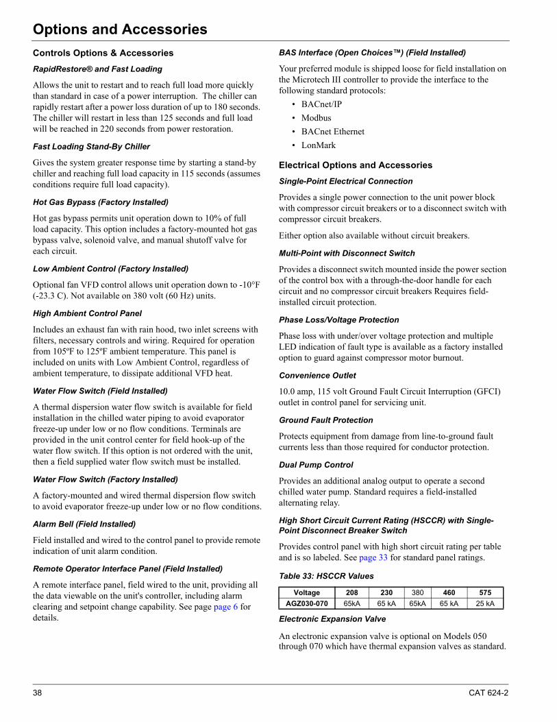
38 CAT 624-2
Options and AccessoriesOptions and Accessories
Controls Options & Accessories
RapidRestore® and Fast Loading
Allows the unit to restart and to reach full load more quickly than standard in case of a power interruption. The chiller can rapidly restart after a power loss duration of up to 180 seconds. The chiller will restart in less than 125 seconds and full load will be reached in 220 seconds from power restoration.
Fast Loading Stand-By Chiller
Gives the system greater response time by starting a stand-by chiller and reaching full load capacity in 115 seconds (assumes conditions require full load capacity).
Hot Gas Bypass (Factory Installed)
Hot gas bypass permits unit operation down to 10% of full load capacity. This option includes a factory-mounted hot gas bypass valve, solenoid valve, and manual shutoff valve for each circuit.
Low Ambient Control (Factory Installed)
Optional fan VFD control allows unit operation down to -10°F (-23.3 C). Not available on 380 volt (60 Hz) units.
High Ambient Control Panel
Includes an exhaust fan with rain hood, two inlet screens with filters, necessary controls and wiring. Required for operation from 105ºF to 125ºF ambient temperature. This panel is included on units with Low Ambient Control, regardless of ambient temperature, to dissipate additional VFD heat.
Water Flow Switch (Field Installed)
A thermal dispersion water flow switch is available for field installation in the chilled water piping to avoid evaporator freeze-up under low or no flow conditions. Terminals are provided in the unit control center for field hook-up of the water flow switch. If this option is not ordered with the unit, then a field supplied water flow switch must be installed.
Water Flow Switch (Factory Installed)
A factory-mounted and wired thermal dispersion flow switch to avoid evaporator freeze-up under low or no flow conditions.
Alarm Bell (Field Installed)
Field installed and wired to the control panel to provide remote indication of unit alarm condition.
Remote Operator Interface Panel (Field Installed)
A remote interface panel, field wired to the unit, providing all the data viewable on the unit's controller, including alarm clearing and setpoint change capability. See page page 6 for details.
BAS Interface (Open Choices™) (Field Installed)
Your preferred module is shipped loose for field installation on the Microtech III controller to provide the interface to the following standard protocols:
• BACnet/IP
• Modbus
• BACnet Ethernet
• LonMark
Electrical Options and Accessories
Single-Point Electrical Connection
Provides a single power connection to the unit power block with compressor circuit breakers or to a disconnect switch with compressor circuit breakers.
Either option also available without circuit breakers.
Multi-Point with Disconnect Switch
Provides a disconnect switch mounted inside the power section of the control box with a through-the-door handle for each circuit and no compressor circuit breakers Requires field-installed circuit protection.
Phase Loss/Voltage Protection
Phase loss with under/over voltage protection and multiple LED indication of fault type is available as a factory installed option to guard against compressor motor burnout.
Convenience Outlet
10.0 amp, 115 volt Ground Fault Circuit Interruption (GFCI) outlet in control panel for servicing unit.
Ground Fault Protection
Protects equipment from damage from line-to-ground fault currents less than those required for conductor protection.
Dual Pump Control
Provides an additional analog output to operate a second chilled water pump. Standard requires a field-installed alternating relay.
High Short Circuit Current Rating (HSCCR) with Single-Point Disconnect Breaker Switch
Provides control panel with high short circuit rating per table and is so labeled. See page 33 for standard panel ratings.
Table 33: HSCCR Values
Electronic Expansion Valve
An electronic expansion valve is optional on Models 050 through 070 which have thermal expansion valves as standard.
Voltage 208 230 380 460 575
AGZ030-070 65kA 65 kA 65kA 65 kA 25 kA
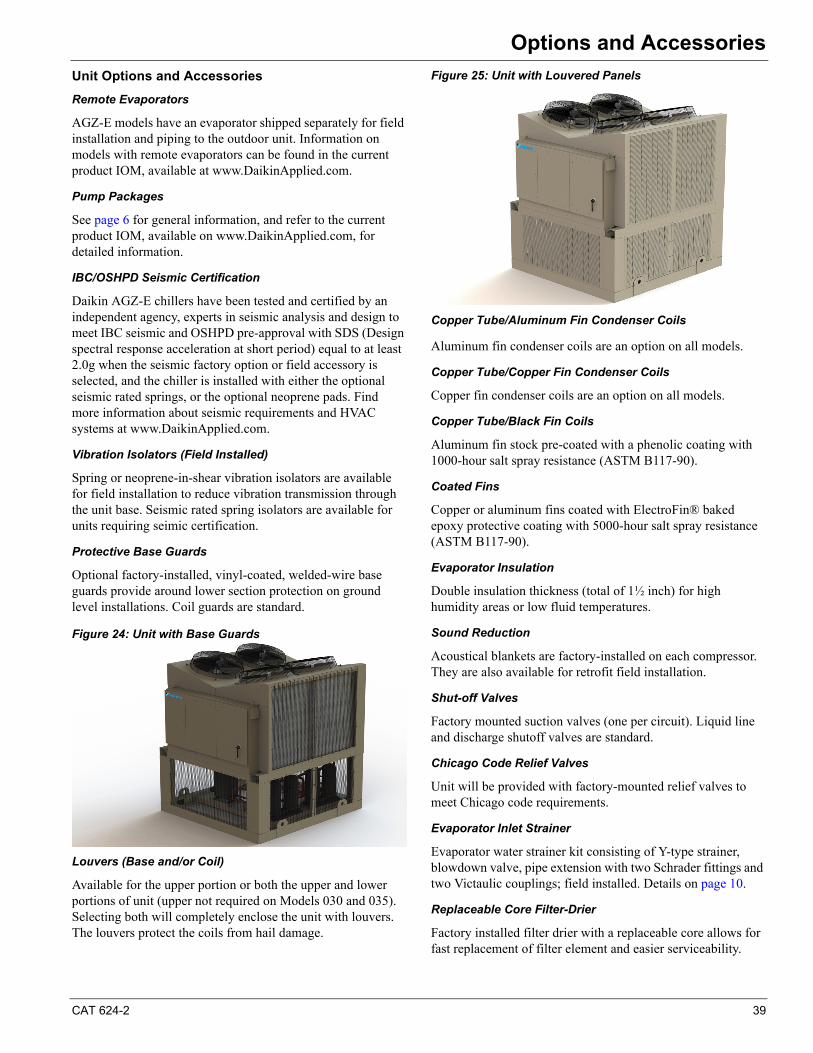
CAT 624-2 39
Options and Accessories
Unit Options and Accessories
Remote Evaporators
AGZ-E models have an evaporator shipped separately for field installation and piping to the outdoor unit. Information on models with remote evaporators can be found in the current product IOM, available at www.DaikinApplied.com.
Pump Packages
See page 6 for general information, and refer to the current product IOM, available on www.DaikinApplied.com, for detailed information.
IBC/OSHPD Seismic Certification
Daikin AGZ-E chillers have been tested and certified by an independent agency, experts in seismic analysis and design to meet IBC seismic and OSHPD pre-approval with SDS (Design spectral response acceleration at short period) equal to at least 2.0g when the seismic factory option or field accessory is selected, and the chiller is installed with either the optional seismic rated springs, or the optional neoprene pads. Find more information about seismic requirements and HVAC systems at www.DaikinApplied.com.
Vibration Isolators (Field Installed)
Spring or neoprene-in-shear vibration isolators are available for field installation to reduce vibration transmission through the unit base. Seismic rated spring isolators are available for units requiring seimic certification.
Protective Base Guards
Optional factory-installed, vinyl-coated, welded-wire base guards provide around lower section protection on ground level installations. Coil guards are standard.
Figure 24: Unit with Base Guards
Louvers (Base and/or Coil)
Available for the upper portion or both the upper and lower portions of unit (upper not required on Models 030 and 035). Selecting both will completely enclose the unit with louvers. The louvers protect the coils from hail damage.
Figure 25: Unit with Louvered Panels
Copper Tube/Aluminum Fin Condenser Coils
Aluminum fin condenser coils are an option on all models.
Copper Tube/Copper Fin Condenser Coils
Copper fin condenser coils are an option on all models.
Copper Tube/Black Fin Coils
Aluminum fin stock pre-coated with a phenolic coating with 1000-hour salt spray resistance (ASTM B117-90).
Coated Fins
Copper or aluminum fins coated with ElectroFin® baked epoxy protective coating with 5000-hour salt spray resistance (ASTM B117-90).
Evaporator Insulation
Double insulation thickness (total of 1½ inch) for high humidity areas or low fluid temperatures.
Sound Reduction
Acoustical blankets are factory-installed on each compressor. They are also available for retrofit field installation.
Shut-off Valves
Factory mounted suction valves (one per circuit). Liquid line and discharge shutoff valves are standard.
Chicago Code Relief Valves
Unit will be provided with factory-mounted relief valves to meet Chicago code requirements.
Evaporator Inlet Strainer
Evaporator water strainer kit consisting of Y-type strainer, blowdown valve, pipe extension with two Schrader fittings and two Victaulic couplings; field installed. Details on page 10.
Replaceable Core Filter-Drier
Factory installed filter drier with a replaceable core allows for fast replacement of filter element and easier serviceability.
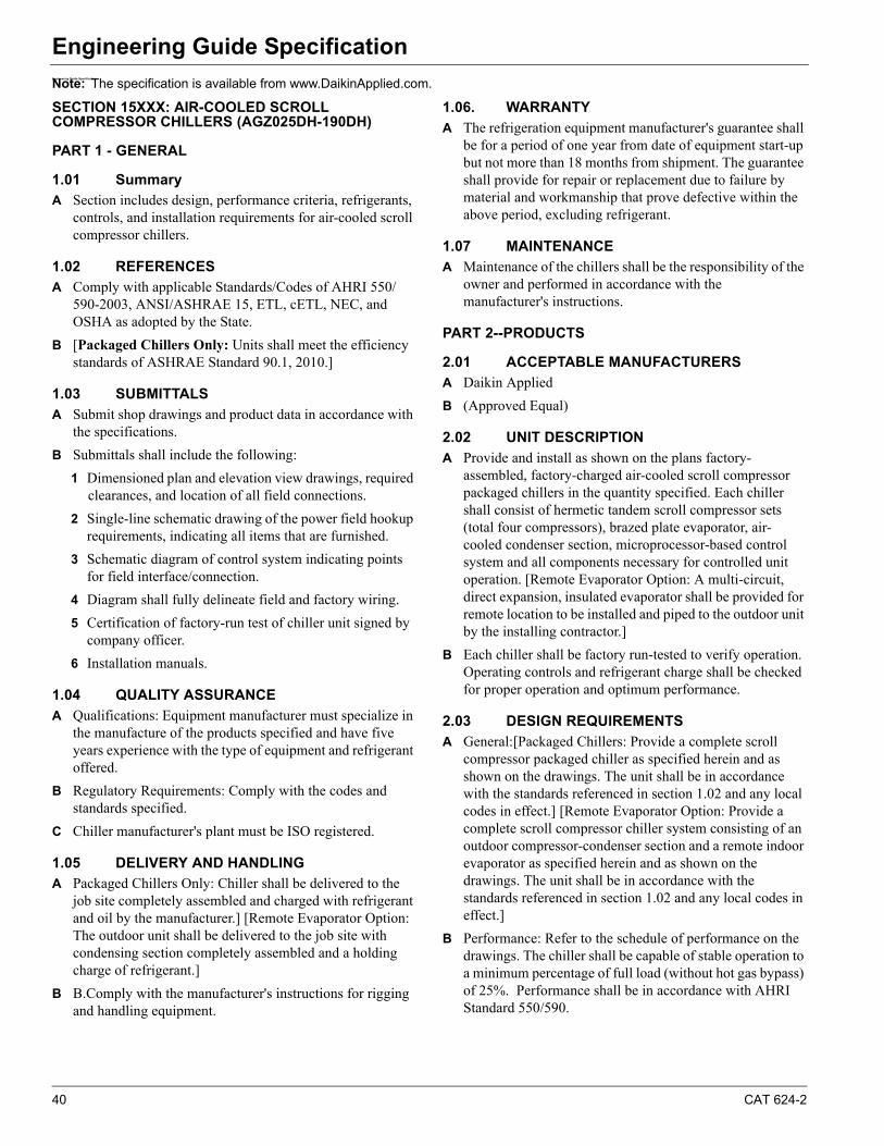
40 CAT 624-2
Engineering Guide SpecificationEngineering Guide Specification
Note: The specification is available from www.DaikinApplied.com.
SECTION 15XXX: AIR-COOLED SCROLL COMPRESSOR CHILLERS (AGZ025DH-190DH)
PART 1 - GENERAL
1.01 Summary
A Section includes design, performance criteria, refrigerants, controls, and installation requirements for air-cooled scroll compressor chillers.
1.02 REFERENCES
A Comply with applicable Standards/Codes of AHRI 550/590-2003, ANSI/ASHRAE 15, ETL, cETL, NEC, and OSHA as adopted by the State.
B [Packaged Chillers Only: Units shall meet the efficiency standards of ASHRAE Standard 90.1, 2010.]
1.03 SUBMITTALS
A Submit shop drawings and product data in accordance with the specifications.
B Submittals shall include the following:
1 Dimensioned plan and elevation view drawings, required clearances, and location of all field connections.
2 Single-line schematic drawing of the power field hookup requirements, indicating all items that are furnished.
3 Schematic diagram of control system indicating points for field interface/connection.
4 Diagram shall fully delineate field and factory wiring.
5 Certification of factory-run test of chiller unit signed by company officer.
6 Installation manuals.
1.04 QUALITY ASSURANCE
A Qualifications: Equipment manufacturer must specialize in the manufacture of the products specified and have five years experience with the type of equipment and refrigerant offered.
B Regulatory Requirements: Comply with the codes and standards specified.
C Chiller manufacturer's plant must be ISO registered.
1.05 DELIVERY AND HANDLING
A Packaged Chillers Only: Chiller shall be delivered to the job site completely assembled and charged with refrigerant and oil by the manufacturer.] [Remote Evaporator Option: The outdoor unit shall be delivered to the job site with condensing section completely assembled and a holding charge of refrigerant.]
B B.Comply with the manufacturer's instructions for rigging and handling equipment.
1.06. WARRANTY
A The refrigeration equipment manufacturer's guarantee shall be for a period of one year from date of equipment start-up but not more than 18 months from shipment. The guarantee shall provide for repair or replacement due to failure by material and workmanship that prove defective within the above period, excluding refrigerant.
1.07 MAINTENANCE
A Maintenance of the chillers shall be the responsibility of the owner and performed in accordance with the manufacturer's instructions.
PART 2--PRODUCTS
2.01 ACCEPTABLE MANUFACTURERS
A Daikin Applied
B (Approved Equal)
2.02 UNIT DESCRIPTION
A Provide and install as shown on the plans factory-assembled, factory-charged air-cooled scroll compressor packaged chillers in the quantity specified. Each chiller shall consist of hermetic tandem scroll compressor sets (total four compressors), brazed plate evaporator, air-cooled condenser section, microprocessor-based control system and all components necessary for controlled unit operation. [Remote Evaporator Option: A multi-circuit, direct expansion, insulated evaporator shall be provided for remote location to be installed and piped to the outdoor unit by the installing contractor.]
B Each chiller shall be factory run-tested to verify operation. Operating controls and refrigerant charge shall be checked for proper operation and optimum performance.
2.03 DESIGN REQUIREMENTS
A General:[Packaged Chillers: Provide a complete scroll compressor packaged chiller as specified herein and as shown on the drawings. The unit shall be in accordance with the standards referenced in section 1.02 and any local codes in effect.] [Remote Evaporator Option: Provide a complete scroll compressor chiller system consisting of an outdoor compressor-condenser section and a remote indoor evaporator as specified herein and as shown on the drawings. The unit shall be in accordance with the standards referenced in section 1.02 and any local codes in effect.]
B Performance: Refer to the schedule of performance on the drawings. The chiller shall be capable of stable operation to a minimum percentage of full load (without hot gas bypass) of 25%. Performance shall be in accordance with AHRI Standard 550/590.
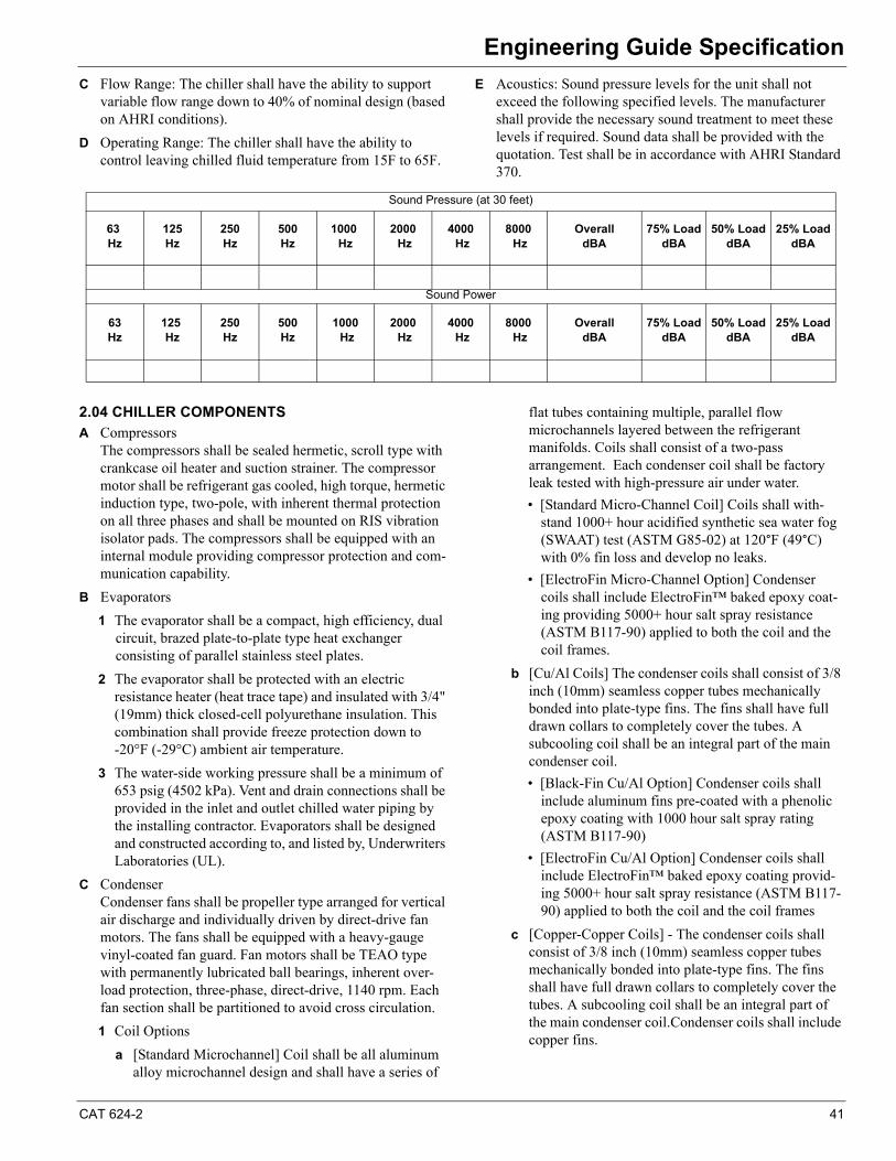
CAT 624-2 41
Engineering Guide Specification
C Flow Range: The chiller shall have the ability to support variable flow range down to 40% of nominal design (based on AHRI conditions).
D Operating Range: The chiller shall have the ability to control leaving chilled fluid temperature from 15F to 65F.
E Acoustics: Sound pressure levels for the unit shall not exceed the following specified levels. The manufacturer shall provide the necessary sound treatment to meet these levels if required. Sound data shall be provided with the quotation. Test shall be in accordance with AHRI Standard 370.
2.04 CHILLER COMPONENTS
A CompressorsThe compressors shall be sealed hermetic, scroll type with crankcase oil heater and suction strainer. The compressor motor shall be refrigerant gas cooled, high torque, hermetic induction type, two-pole, with inherent thermal protection on all three phases and shall be mounted on RIS vibration isolator pads. The compressors shall be equipped with an internal module providing compressor protection and com-munication capability.
B Evaporators
1 The evaporator shall be a compact, high efficiency, dual circuit, brazed plate-to-plate type heat exchanger consisting of parallel stainless steel plates.
2 The evaporator shall be protected with an electric resistance heater (heat trace tape) and insulated with 3/4" (19mm) thick closed-cell polyurethane insulation. This combination shall provide freeze protection down to -20°F (-29°C) ambient air temperature.
3 The water-side working pressure shall be a minimum of 653 psig (4502 kPa). Vent and drain connections shall be provided in the inlet and outlet chilled water piping by the installing contractor. Evaporators shall be designed and constructed according to, and listed by, Underwriters Laboratories (UL).
C CondenserCondenser fans shall be propeller type arranged for vertical air discharge and individually driven by direct-drive fan motors. The fans shall be equipped with a heavy-gauge vinyl-coated fan guard. Fan motors shall be TEAO type with permanently lubricated ball bearings, inherent over-load protection, three-phase, direct-drive, 1140 rpm. Each fan section shall be partitioned to avoid cross circulation.
1 Coil Options
a [Standard Microchannel] Coil shall be all aluminum alloy microchannel design and shall have a series of
flat tubes containing multiple, parallel flow microchannels layered between the refrigerant manifolds. Coils shall consist of a two-pass arrangement. Each condenser coil shall be factory leak tested with high-pressure air under water.
• [Standard Micro-Channel Coil] Coils shall with-stand 1000+ hour acidified synthetic sea water fog (SWAAT) test (ASTM G85-02) at 120°F (49°C) with 0% fin loss and develop no leaks.
• [ElectroFin Micro-Channel Option] Condenser coils shall include ElectroFin™ baked epoxy coat-ing providing 5000+ hour salt spray resistance (ASTM B117-90) applied to both the coil and the coil frames.
b [Cu/Al Coils] The condenser coils shall consist of 3/8 inch (10mm) seamless copper tubes mechanically bonded into plate-type fins. The fins shall have full drawn collars to completely cover the tubes. A subcooling coil shall be an integral part of the main condenser coil.
• [Black-Fin Cu/Al Option] Condenser coils shall include aluminum fins pre-coated with a phenolic epoxy coating with 1000 hour salt spray rating (ASTM B117-90)
• [ElectroFin Cu/Al Option] Condenser coils shall include ElectroFin™ baked epoxy coating provid-ing 5000+ hour salt spray resistance (ASTM B117-90) applied to both the coil and the coil frames
c [Copper-Copper Coils] - The condenser coils shall consist of 3/8 inch (10mm) seamless copper tubes mechanically bonded into plate-type fins. The fins shall have full drawn collars to completely cover the tubes. A subcooling coil shall be an integral part of the main condenser coil.Condenser coils shall include copper fins.
Sound Pressure (at 30 feet)
63 Hz
125Hz
250Hz
500Hz
1000 Hz
2000 Hz
4000 Hz
8000 Hz
OveralldBA
75% Load dBA
50% Load dBA
25% Load dBA
Sound Power
63Hz
125 Hz
250Hz
500Hz
1000 Hz
2000 Hz
4000 Hz
8000 Hz
OveralldBA
75% Load dBA
50% Load dBA
25% Load dBA
42 CAT 624-2
Engineering Guide Specification
• [ElectroFin Cu/Cu Option] Condenser coils shall include ElectroFin™ baked epoxy coating provid-ing 5000+ hour salt spray resistance (ASTM B117-90) applied to both the coil and the coil frames.
D Refrigerant Circuit
1 Each of the two refrigerant circuits shall include a refrigerant filter-drier, sight glass with moisture indicator, liquid line solenoid valve (no exceptions), expansion valve, and insulated suction line.
2 [Optional] Each of the two refrigerant circuits shall include a replaceable-core refrigerant filter-drier, sight glass with moisture indicator, liquid line solenoid valve (no exceptions), expansion valve, and insulated suction line.
E Construction
1 Unit casing and all structural members and rails shall be fabricated of pre-painted or galvanized steel to meet ASTM B117, 500-hour salt spray test.
2 OPTIONS
a Painted steel wraps enclosing the coil end sections and piping
b Protective, 12 GA, PVC-coated, wire coil guards for the vertical upper coil section of the unit
c Protective, 12 GA, PVC-coated, wire base guards for the lower section of the unit
d Protective and decorative louvers for upper section of the unit, covering the coils and unit end
e Protective and decorative louvers for lower section of the unit
F Control System
1 A centrally located weatherproof control panel shall contain the field power connection points, control interlock terminals, and control system. Power and starting components shall include factory circuit breaker for fan motors and control circuit, individual contactors for each fan motor, solid-state compressor three-phase motor overload protection, inherent fan motor overload protection and two power blocks (one per circuit) for connection to remote, contractor supplied disconnect switches. Hinged access doors shall be lockable. Barrier panels or separate enclosures are required to protect against accidental contact with line voltage when accessing the control system.
2 OPTIONS
a [Shall include standard multi-point power blocks. ]
b [Shall include single-point power connection to power block with compressor circuit breakers (Customer-supplied disconnect required).]
c [Shall include single-point connection to a non-fused disconnect switch with through-the-door handle and compressor circuit breakers. ]
d [Shall include multi-point disconnect switches (one per circuit).]
e [Shall include high short circuit current rating of 65,000 amps (25,000 amps at 575Volt) with single-point disconnect switch.][Shall include multi-point disconnect switches (one per circuit).]
G An advanced DDC microprocessor unit controller with a 5-line by 22-character liquid crystal display provides the operating and protection functions. The controller shall take preemptive limiting action in case of high discharge pressure or low evaporator pressure. The controller shall contain the following features as a minimum:
1 Equipment Protection
a The unit shall be protected in two ways: (1) by alarms that shut the unit down and require manual reset to restore unit operation and (2) by limit alarms that reduce unit operation in response to some out-of-limit condition. Shut down alarms shall activate an alarm signal.
b Shutdown Alarms
• No evaporator water flow
• Sensor failures
• Low evaporator pressure
• Evaporator freeze protection
• High condenser pressure
• Outside ambient temperature (auto-restart)
• Motor protection system
• Phase voltage protection (Optional)
c Limit Alarms
• Condenser pressure stage down, unloads unit at high discharge pressures
• Low ambient lockout, shuts off unit at low ambient temperatures
• Low evaporator pressure hold, holds stage #1 until pressure rises
• Low evaporator pressure unload, shuts off one com-pressor
d Unit Enable Selection
• Enables unit operation from either local keypad, digital input, or BAS
e Unit Mode Selection
• Selects standard cooling, ice, glycol, or test opera-tion mode
f Analog Inputs
• Reset of leaving water temperature, 4-20 mA
• Current Limit
g Digital Inputs
• Unit off switch
• Remote start/stop
CAT 624-2 43
Engineering Guide Specification
• Flow switch
• Ice mode switch, converts operation and setpoints for ice production
• Motor protection
h Digital Outputs
• Shutdown alarm; field wired, activates on an alarm condition, off when alarm is cleared
• Evaporator pump; field wired, starts pump when unit is set to start
i Condenser Fan Control
• The unit controller shall provide control of con-denser fans based on compressor discharge pressure.
j Building Automation System (BAS) Interface
• Factory mounted DDC controller(s) shall support operation on a BACnet®, Modbus® or LONMARK® network via one of the data link / physical layers listed below as specified by the successful Building Automation System (BAS) supplier.
• BACnet MS/TP master (Clause 9)
• BACnet IP, (Annex J)
• BACnet ISO 8802-3, (Ethernet)
• LONMARK FTT-10A. The unit controller shall be LONMARK® certified.
• The information communicated between the BAS and the factory mounted unit controllers shall include the reading and writing of data to allow unit monitor-ing, control and alarm notification as specified in the unit sequence of operation and the unit points list.
• For chillers communicating over a LONMARK net-work, the corresponding LONMARK eXternal Inter-face File (XIF) shall be provided with the chiller submittal data.
• All communication from the chiller unit controller as specified in the points list shall be via standard BACnet objects. Proprietary BACnet objects shall not be allowed. BACnet communications shall conform to the BACnet protocol (ANSI/ASHRAE135-2001). A BACnet Protocol Implementation Conformance Statement (PICS) shall be provided along with the unit submittal.
2.05 OPTIONS AND ACCESSORIES
A The following optional items shall be furnished:
• Rapid Restore™ and Fast Loading: The chiller shall be equipped with the capability to restart and to reach full load more quickly than standard in case of a power interruption. The chiller shall be capable of rapidly restarting after power loss duration of up to 180 seconds. The time to restart the chiller shall be a maximum of 125 seconds, and full load shall be achieved in 220 seconds from power restoration.
• Fast Loading Stand-By Chiller: The chiller shall be equipped with the capability to start and to reach full load more quickly than standard in the event that the primary chiller system is disabled. The chiller shall be capable of rapidly achieving full capacity. The time to full load shall be achieved in 115 seconds.
• Seismic Certification: Optional IBC seismic and OSHPD pre-approval shall meet a minimum seismic design spectral response acceleration SDS of 2.0g and
be so labeled. The chiller must be mounted on optional seismic rated spring isolators or neoprene waffle vibration pads.
• Hot Gas Bypass: allows unit operation to 10 percent of full load. Includes factory-mounted hot gas bypass valve, solenoid valve, and manual shutoff valve for each circuit. Shall be ready for field piping according to manufacturer instructions.
• Low Ambient Control: Fan VFD allows unit opera-tion from 32°F down to -10°F (-23.3 C).
• High ambient control box for operation in ambient temperatures from 105°F to 125°F
• Ground Fault Protection: Factory installed circuit breaker to protect equipment from damage from line-to-ground fault currents less than those required for conductor protection.
• Phase loss with under/over voltage protection and with LED indication of the fault type to guard against compressor motor burnout.
• Factory-mounted thermal dispersion flow switch
• Field-mounted, paddle type, chilled water flow switch field wired to the control panel
• Evaporator inlet strainer, 40-mesh with extension pipe and Victaulic couplings (factory mounted or field installed)
• Spring vibration isolators (field installed)
• Rubber-in-shear vibration isolators (field installed)
• Seismic rated spring isolators (field installed)
• Compressor sound reduction package
• Remote operator interface panel (field-wired)
• 115V GFI convenience outlet
• BAS interface module, factory mounted
2.06 Optional Factory-Installed Pump Package
A The pump package shall be factory mounted and wired on the chiller. The chiller controller shall provide a pump start/stop signal when operation is required. On dual pump systems, the chiller shall also provide automatic alternating of pump starts and duty/standby functionality. The package shall be equipped with:
• Single Pump Model 4380: single spring inside-seal, vertical, in-line, radially split-case pump, ser-viceable without breaking pipe connections. The
44 CAT 624-2
Engineering Guide Specification
motor and pump rotating assembly shall be service-able without removing the pump casing from the line, or...
• Dual Pumps in a Single Casting Model 4392: sin-gle-spring inside-seal vertical, in-line, radially split-case pumps, mounted in a common casing with a common inlet connection and outlet connection and including a flapper valve to prevent recirculation when only one pump is operating. An isolation valve shall be included to allow one pump to operate when the other is removed. The pumps shall be designed for duty/standby, not parallel operation.
Pump package shall also be equipped with:
• "Y" type inlet strainer
• Combination triple-duty outlet valve having a drip-tight discharge shutoff valve, non-slam check valve, and flow throttling valve
• Combination suction guide with flow stabilizing outlet vanes and stainless steel strainer with a dispos-able fine-mesh strainer for start-up
• Factory power and control wiring from the AGZ chiller to the pump package control panel
• Flow switch mounted and wired
• Interconnecting schedule 40 piping with Victaulic couplings
• Insulation of all cold surfaces
B Pump Package Options
• Water pressure gauges on the pump suction and dis-charge
• Expansion tank with size increments from 4.4 to 90 gallons, field installed (small sizes can be factory mounted)
• Air separator with air vent, field installed
• Storage tanks, vertical, insulated, 150, 300, 600, 1000 gallon sizes with optional immersion heater, field installed
• Pump VFD for variable chilled water flow capabil-ity.
• The VFD shall be completely sensorless requiring no field installation or wiring of sensors. The drive shall incorporate an integrated graphical user interface that shall provide running and diag-nostic information and identify faults and status in clear English language. Faults shall be logged / recorded for interrogation at a later date. The keypad shall incorporate Hand-Off-Auto push-buttons to enable switching between auto control modes and manual control. The drive shall incor-
porate a USB port for direct connection to a PC and an RS485 connection with Modbus RTU pro-tocol. The built-in BAS mode shall be equipped with the same protocol as the chiller.
• Control software shall provide automatic speed control in variable volume systems without the need for pump mounted (internal/external) or remotely mounted differential pressure system feedback sensor. Control mode setting and mini-mum / maximum head and flow set-points shall be set at the factory and be user adjustable via the inbuilt programming interface.
PART 3 - EXECUTION
3.01 INSTALLATION
A Install in strict accordance with manufacturer's requirements, shop drawings, and contract documents.
B Adjust and level chiller in alignment on supports.
C Coordinate electrical installation with electrical contractor.
D Coordinate controls with control contractor.
E Install a cleanable, field-supplied 40-mesh strainer in the chilled water return line at the evaporator inlet.
3.02 START-UP
A Provide testing and starting of machine, and instruct the Owner in its proper operation and maintenance.


© 2014 Daikin Applied • www.DaikinApplied.com • 800-432-1342 4/14
Daikin Applied Training and Development
Now that you have made an investment in modern, efficient Daikin Applied equipment, its care should be a high priority. For training information on all Daikin Applied HVAC products, please visit us at www.DaikinApplied.com and click on Training, or call 540-248-9646 to speak to the Training Department.
Warranty
All Daikin Applied equipment is sold pursuant to its standard terms and conditions of sale, including Limited Product Warranty. Consult your local Daikin Applied representative for warranty details. To find your local Daikin Applied representative, go to www.DaikinApplied.com.
Aftermarket Services
To find your local parts office, visit www.DaikinApplied.com or call 800-37PARTS (800-377-2787). To find your local service office, visit www.DaikinApplied.com or call 800-432-1342.
This document contains the most current product information as of this printing. For the most up-to-date product information, please go to www.DaikinApplied.com.