Embed Size (px)
Citation preview
MICROSTATION TIPS AND TRICKS
March 1, 2013
FAQ
Keyboard Accelerators
Tips for Beginners
General Tips and Tricks
Text Tips
Reference Tips
3D Tips
Design Files from Outside Sources
Customizing Microstation
Google Earth & Microstation
Frequently Asked Questions
PROBLEM: FIXING WRONG WORKING UNITS
Someone created a design file using the wrong working units. I would like to fix this without having to redo the entire drawing, can I do this?
Yes, you will have to change the working units. Doing so may move and re-scale the elements in the drawing. You will have to do a little work after you change the working units. We have a set of instructions that tell how to do this in the "Design Files from Outside Sources" section of this document.
PROBLEM: Microstation has Two Windows.
I noticed that Roadway Design preference use two windows, do I have to use this and what is the advantage?
You do not have to use two application windows if you only have one monitor. This is a preference, so set it the way you like. Roadway sets this as its default because of a couple of advantages it provides. One thing it does is it eliminates items in Microstation from being split in the center of the two monitors. If you do not have two monitors then you probably would want to set it back to one. Another advantage with two application windows is that you now have additional sides in which to dock tools.
To change it back to one application window, go the the Workspace > Preference menu selection and find the category called "Operation" and turn off "Open two application windows" by un-checking it.
PROBLEM: Converting 3D to 2D
How do you convert a 3D file to 2D, or a 2D to 3D?
This can be within Microstation by entering the file to be converted and selecting the FILE > EXPORT > 2D Command.
There are a few things that you should do before converting.
1. Conversion is done by what shows up in the view. So be sure that all the elements you what to be in the 2D file shows up in the view. While in 3D, make sure you see all the elements. In 3D, the display depth can be set were all elements are not seen in the view.
2. When converting a file, the reference files can be converted also. We recommend that you detach or turn the display off on reference files to make sure not to convert them at the same time. If you want to convert the other files that are being referenced you should do them separately.
3. If you plan to convert the 3D file to 2D then back to 3D you can save the Z elevation information in the 2D conversion so that it will be restored. Just check the "Preserve Z Range" option.
4. Since your view can be rotated, the rotation is considered in the conversion, so either make sure you have the view orientation correct before converting or if you can select the "Ignore View Rotation" option before converting.
PROBLEM: Line Styles are not showing correct.
Line styles such as pipes and utilities do no show correctly, what's wrong?
All line styles depend on Roadway Design's line style resource file (rwdsty.rsc) to make them display properly. If they don't appear correct, the problem can be fixed by making sure you enter the design file using the correct workspace. You may be getting in an English file using a Metric workspace or vice-versa. If this does not correct the problem then you may have a missing resource file on your machine. Make sure your rwddata directories exist in their complete versions and configured with the delivered setup porgram.
PROBLEM: Attached References not showing up
I have attached some reference files from another directory. When I re-enter a design file the reference files will not show. Why not?
Microstation under default conditions will not remember the full path name to the design file. This is why the reference does not show up or appears in read. The other reason is the file that is being referenced no longer exist or the name has been changed. DO NOT use full path names for reference file attachments. By default we do not save the full path directory name when attaching a reference file. Under our normal working conditions it is a very bad idea to attach files from another directory. All project related files should be in the same directory for referencing. The exception are the files that are used over and over again, like some files in the group or input folders. It is not practical to have these files in every project so we have one them in other folders. We use environment variables (GR and INP) to represent the location of these files in the group and input folders. Microstation will save the attachment using these variables. This variable is included in the workspace and can be used over and over. This is turn eliminates the need to attach reference files with full path names.
PROBLEM: CUSTOMIZING MICROSTATION
I like to customize my tools, and would like to be able to add things like Function Key Menus and make my own cell libraries, but I'm have trouble figuring out how. Can I found help on these topics?

Yes, a section has been included in this document on show how to customize some of the thing you mentioned. Just click on the "Customizing Microstation" link to read the topics. We do not support personal customization and the only instructions given are located in this document. Try to follow these instructions closely for they could save you some headaches.

Microstation Keyboard Accelerators
Microstation 2 Letter Key-in Accelerators
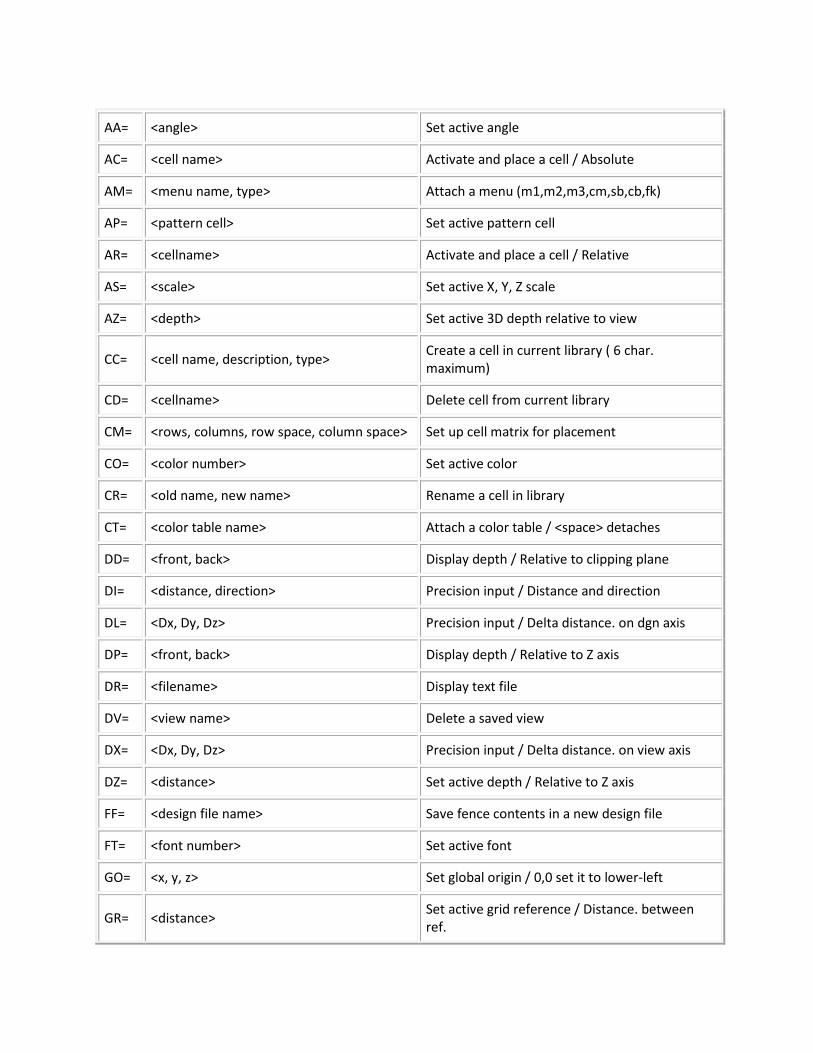
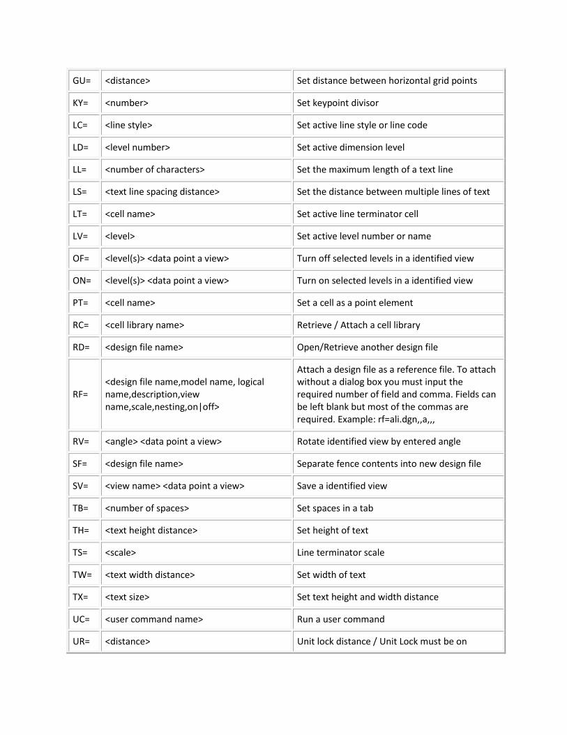
Microstation has many built-in key-ins. These are not used as often as they once were, but are still very useful. Microstation has incorporated many dialog and tool boxes that have taken the place of these key-ins. In some cases, these new tools have helped, but in some cases they have slowed down the process. Although the new tools may be easier to learn, they are not always the fastest way to get things done. Let's look at an example, Suppose you are creating a cell. Many user would activate the cells dialog box, and then use the Create button, etc. The problem with this is that you have to click on a lot of buttons and boxes to get the job done, all the while, switching between mouse and keyboard. If you are creating many cells, then this process can be time consuming. But if you use the key-in method, you can save from having to click all those buttons and boxes. Just key in "cc=name,description", hit Enter, and the job is done.
AA= <angle> Set active angle
AC= <cell name> Activate and place a cell / Absolute
AM= <menu name, type> Attach a menu (m1,m2,m3,cm,sb,cb,fk)
AP= <pattern cell> Set active pattern cell
AR= <cellname> Activate and place a cell / Relative
AS= <scale> Set active X, Y, Z scale
AZ= <depth> Set active 3D depth relative to view
CC= <cell name, description, type> Create a cell in current library ( 6 char. maximum)
CD= <cellname> Delete cell from current library
CM= <rows, columns, row space, column space> Set up cell matrix for placement
CO= <color number> Set active color
CR= <old name, new name> Rename a cell in library
CT= <color table name> Attach a color table / <space> detaches
DD= <front, back> Display depth / Relative to clipping plane
DI= <distance, direction> Precision input / Distance and direction
DL= <Dx, Dy, Dz> Precision input / Delta distance. on dgn axis
DP= <front, back> Display depth / Relative to Z axis
DR= <filename> Display text file
DV= <view name> Delete a saved view
DX= <Dx, Dy, Dz> Precision input / Delta distance. on view axis
DZ= <distance> Set active depth / Relative to Z axis
FF= <design file name> Save fence contents in a new design file
FT= <font number> Set active font
GO= <x, y, z> Set global origin / 0,0 set it to lower-left
GR= <distance> Set active grid reference / Distance. between ref.
GU= <distance> Set distance between horizontal grid points
KY= <number> Set keypoint divisor
LC= <line style> Set active line style or line code
LD= <level number> Set active dimension level
LL= <number of characters> Set the maximum length of a text line
LS= <text line spacing distance> Set the distance between multiple lines of text
LT= <cell name> Set active line terminator cell
LV= <level> Set active level number or name
OF= <level(s)> <data point a view> Turn off selected levels in a identified view
ON= <level(s)> <data point a view> Turn on selected levels in a identified view
PT= <cell name> Set a cell as a point element
RC= <cell library name> Retrieve / Attach a cell library
RD= <design file name> Open/Retrieve another design file
RF= <design file name,model name, logical name,description,view name,scale,nesting,on|off>
Attach a design file as a reference file. To attach without a dialog box you must input the required number of field and comma. Fields can be left blank but most of the commas are required. Example: rf=ali.dgn,,a,,,
RV= <angle> <data point a view> Rotate identified view by entered angle
SF= <design file name> Separate fence contents into new design file
SV= <view name> <data point a view> Save a identified view
TB= <number of spaces> Set spaces in a tab
TH= <text height distance> Set height of text
TS= <scale> Line terminator scale
TW= <text width distance> Set width of text
TX= <text size> Set text height and width distance
UC= <user command name> Run a user command
UR= <distance> Unit lock distance / Unit Lock must be on
VI= <name> or <top, front, back, iso, etc> Attach a saved view or standard view
WO= <x, y, z> <identify a window> Set origin of window at lower-left
WT= <weight number> Set active weight of elements placed
XY= <x, y, z> Precision input / Absolute Point
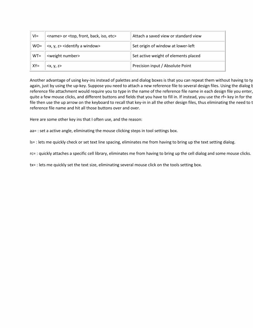
Another advantage of using key-ins instead of palettes and dialog boxes is that you can repeat them without having to typ again, just by using the up-key. Suppose you need to attach a new reference file to several design files. Using the dialog b reference file attachment would require you to type in the name of the reference file name in each design file you enter, quite a few mouse clicks, and different buttons and fields that you have to fill in. If instead, you use the rf= key in for the f file then use the up arrow on the keyboard to recall that key-in in all the other design files, thus eliminating the need to ty reference file name and hit all those buttons over and over.
Here are some other key ins that I often use, and the reason:
aa= : set a active angle, eliminating the mouse clicking steps in tool settings box.
ls= : lets me quickly check or set text line spacing, eliminates me from having to bring up the text setting dialog.
rc= : quickly attaches a specific cell library, eliminates me from having to bring up the cell dialog and some mouse clicks.
tx= : lets me quickly set the text size, eliminating several mouse click on the tools setting box.
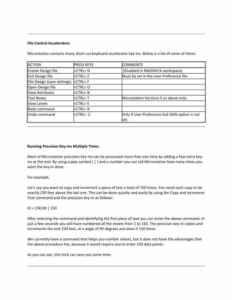
File Control Accelerators
Microstation contains many short cut keyboard accelerator key-ins. Below is a list of some of these:
ACTION PRESS KEYS COMMENTS Create Design file <CTRL> N (Disabled in RWDDATA workspace) Exit Design file <CTRL> Z Must be set in the User Preference file. File Design (save settings) <CTRL> F Open Design file <CTRL> O View Attributes <CTRL> B Tool Boxes <CTRL> T Microstation Versions 5 or above only. View Levels <CTRL> E Redo command <CTRL> R Undo command <CTRL> Z Only if User Preference Exit DGN option is not
set.
Running Precision Key-ins Multiple Times
Most of Microstation precision key-ins can be processed more than one time by adding a few extra key-ins at the end. By using a pipe symbol ( | ) and a number you can tell Microstation how many times you want the key-in done.
For example,
Let's say you want to copy and increment a piece of text a total of 150 times. You need each copy to be exactly 230 feet above the last one. This can be done quickly and easily by using the Copy and Increment Text command and the precision key-in as follows:
DI = 230,90 | 150
After selecting the command and identifying the first piece of text you can enter the above command. In just a few seconds you will have numbered all the sheets from 1 to 150. The precision key-in copies and increments the text 230 feet, at a angle of 90 degrees and does it 150 times.
We currently have a command that helps you number sheets, but it does not have the advantages that the above procedure has, because it would require you to enter 150 data points.
As you can see, this trick can save you some time.
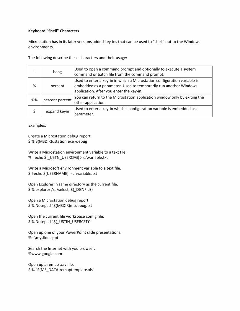
Keyboard "Shell" Characters
Microstation has in its later versions added key-ins that can be used to "shell" out to the Windows environments.
The following describe these characters and their usage:
! bang Used to open a command prompt and optionally to execute a system command or batch file from the command prompt.
% percent Used to enter a key-in in which a Microstation configuration variable is embedded as a parameter. Used to temporarily run another Windows application. After you enter the key-in.
%% percent percent You can return to the Microstation application window only by exiting the other application.
$ expand keyin Used to enter a key-in which a configuration variable is embedded as a parameter.
Examples:
Create a Microstation debug report. $ % $(MSDIR)ustation.exe -debug
Write a Microstation environment variable to a text file. % ! echo $(_USTN_USERCFG) > c:\variable.txt
Write a Microsoft environment variable to a text file. $ ! echo $(USERNAME) > c:\variable.txt
Open Explorer in same directory as the current file. $ % explorer /s, /select, $(_DGNFILE)
Open a Microstation debug report. $ % Notepad "$(MSDIR)msdebug.txt
Open the current file workspace config file. $ % Notepad "$(_USTIN_USERCFT)"
Open up one of your PowerPoint slide presentations. %c:\myslides.ppt
Search the Internet with you browser. %www.google.com
Open up a remap .csv file. $ % "$(MS_DATA)remaptemplate.xls"
Tips For Beginners
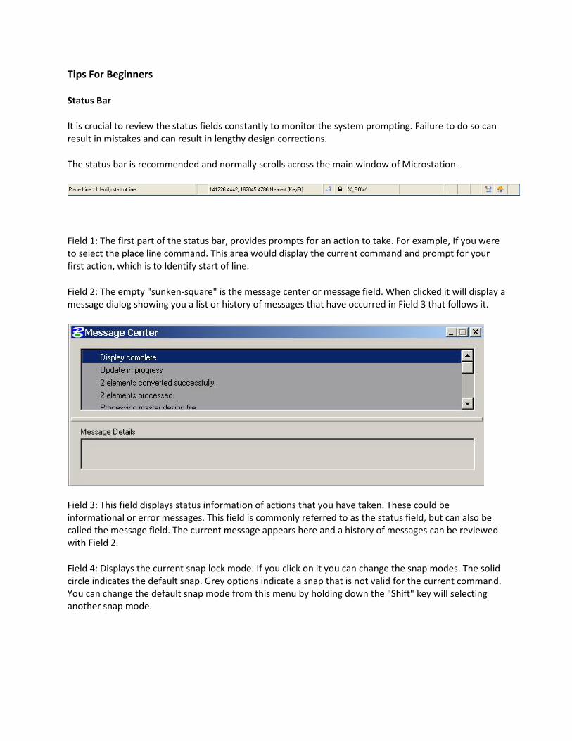
Status Bar
It is crucial to review the status fields constantly to monitor the system prompting. Failure to do so can result in mistakes and can result in lengthy design corrections.
The status bar is recommended and normally scrolls across the main window of Microstation.
Field 1: The first part of the status bar, provides prompts for an action to take. For example, If you were to select the place line command. This area would display the current command and prompt for your first action, which is to Identify start of line.
Field 2: The empty "sunken-square" is the message center or message field. When clicked it will display a message dialog showing you a list or history of messages that have occurred in Field 3 that follows it.
Field 3: This field displays status information of actions that you have taken. These could be informational or error messages. This field is commonly referred to as the status field, but can also be called the message field. The current message appears here and a history of messages can be reviewed with Field 2.
Field 4: Displays the current snap lock mode. If you click on it you can change the snap modes. The solid circle indicates the default snap. Grey options indicate a snap that is not valid for the current command. You can change the default snap mode from this menu by holding down the "Shift" key will selecting another snap mode.
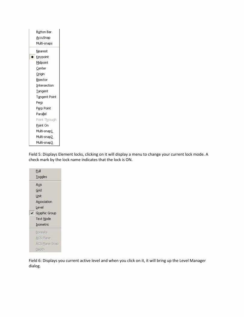
Field 5: Displays Element locks, clicking on it will display a menu to change your current lock mode. A check mark by the lock name indicates that the lock is ON.
Field 6: Displays you current active level and when you click on it, it will bring up the Level Manager dialog.
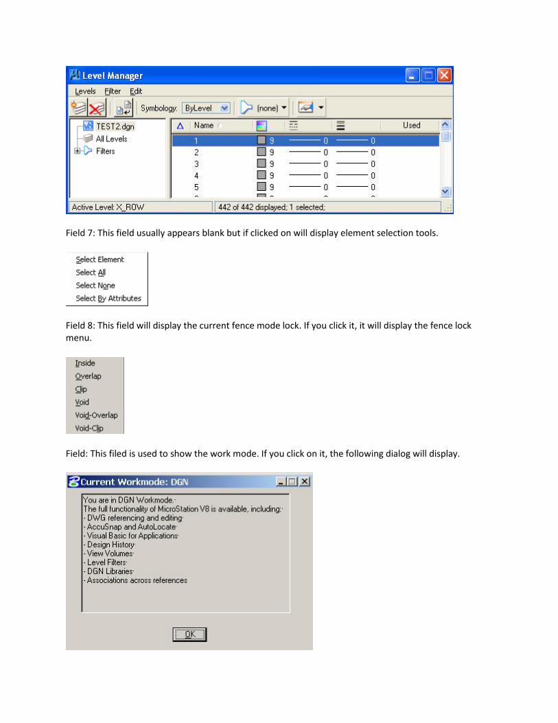
Field 7: This field usually appears blank but if clicked on will display element selection tools.
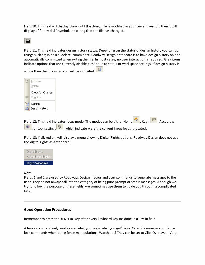
Field 8: This field will display the current fence mode lock. If you click it, it will display the fence lock menu.
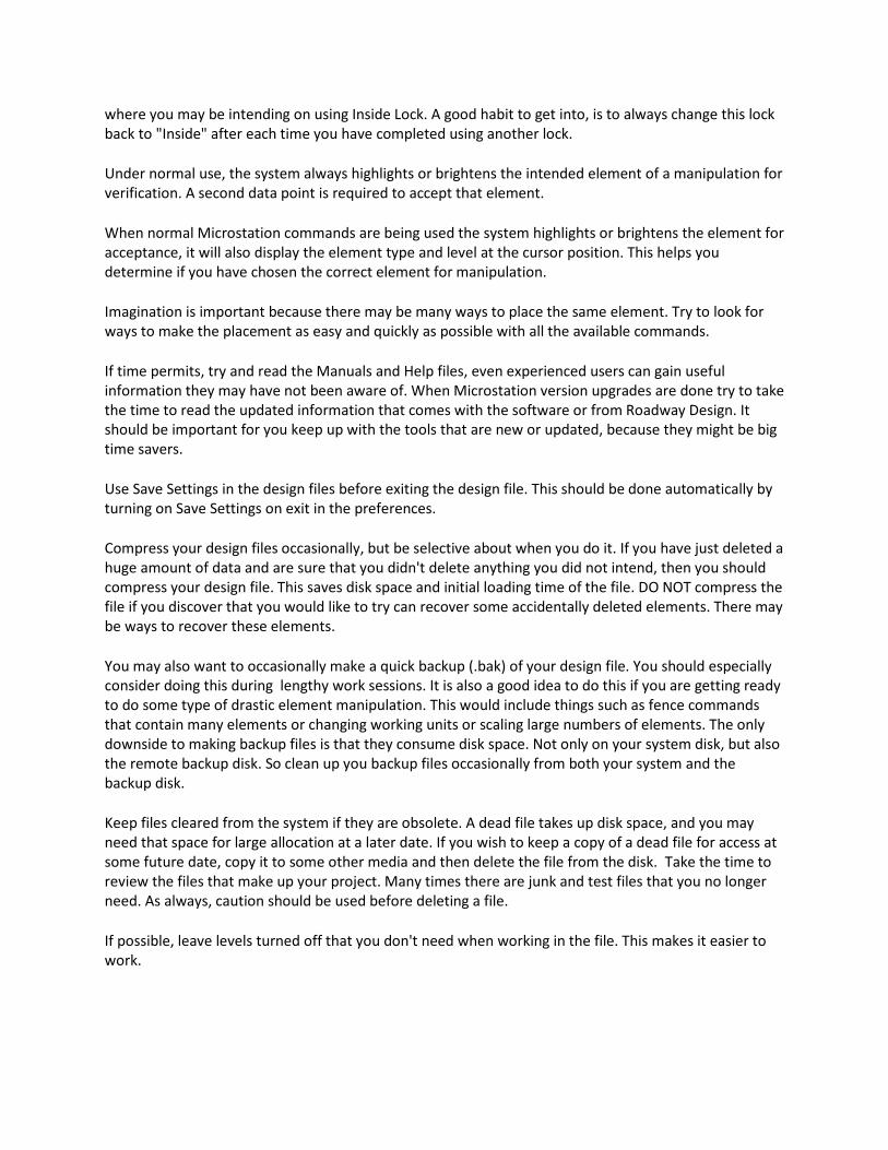
Field: This filed is used to show the work mode. If you click on it, the following dialog will display.
Field 10: This field will display blank until the design file is modified in your current session, then it will display a "floppy disk" symbol. Indicating that the file has changed.
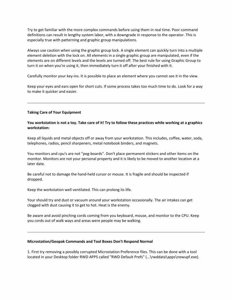
Field 11: This field indicates design history status. Depending on the status of design history you can do things such as; Initialize, delete, commit etc. Roadway Design's standard is to have design history on and automatically committed when exiting the file. In most cases, no user interaction is required. Grey items indicate options that are currently disable either due to status or workspace settings. If design history is
active then the following icon will be indicated:
Field 12: This field indicates focus mode. The modes can be either Home , Keyin , Accudraw
, or tool settings , which indicate were the current input focus is located.
Field 13: If clicked on, will display a menu showing Digital Rights options. Roadway Design does not use the digital rights as a standard.
Note: Fields 1 and 2 are used by Roadways Design macros and user commands to generate messages to the user. They do not always fall into the category of being pure prompt or status messages. Although we try to follow the purpose of these fields, we sometimes use them to guide you through a complicated task.
Good Operation Procedures
Remember to press the <ENTER> key after every keyboard key-ins done in a key-in field.
A fence command only works on a ‘what you see is what you get’ basis. Carefully monitor your fence lock commands when doing fence manipulations. Watch out! They can be set to Clip, Overlay, or Void
where you may be intending on using Inside Lock. A good habit to get into, is to always change this lock back to "Inside" after each time you have completed using another lock.
Under normal use, the system always highlights or brightens the intended element of a manipulation for verification. A second data point is required to accept that element.
When normal Microstation commands are being used the system highlights or brightens the element for acceptance, it will also display the element type and level at the cursor position. This helps you determine if you have chosen the correct element for manipulation.
Imagination is important because there may be many ways to place the same element. Try to look for ways to make the placement as easy and quickly as possible with all the available commands.
If time permits, try and read the Manuals and Help files, even experienced users can gain useful information they may have not been aware of. When Microstation version upgrades are done try to take the time to read the updated information that comes with the software or from Roadway Design. It should be important for you keep up with the tools that are new or updated, because they might be big time savers.
Use Save Settings in the design files before exiting the design file. This should be done automatically by turning on Save Settings on exit in the preferences.
Compress your design files occasionally, but be selective about when you do it. If you have just deleted a huge amount of data and are sure that you didn't delete anything you did not intend, then you should compress your design file. This saves disk space and initial loading time of the file. DO NOT compress the file if you discover that you would like to try can recover some accidentally deleted elements. There may be ways to recover these elements.
You may also want to occasionally make a quick backup (.bak) of your design file. You should especially consider doing this during lengthy work sessions. It is also a good idea to do this if you are getting ready to do some type of drastic element manipulation. This would include things such as fence commands that contain many elements or changing working units or scaling large numbers of elements. The only downside to making backup files is that they consume disk space. Not only on your system disk, but also the remote backup disk. So clean up you backup files occasionally from both your system and the backup disk.
Keep files cleared from the system if they are obsolete. A dead file takes up disk space, and you may need that space for large allocation at a later date. If you wish to keep a copy of a dead file for access at some future date, copy it to some other media and then delete the file from the disk. Take the time to review the files that make up your project. Many times there are junk and test files that you no longer need. As always, caution should be used before deleting a file.
If possible, leave levels turned off that you don't need when working in the file. This makes it easier to work.
Try to get familiar with the more complex commands before using them in real time. Poor command definitions can result in lengthy system labor, with a downgrade in response to the operator. This is especially true with patterning and graphic group manipulations.
Always use caution when using the graphic group lock. A single element can quickly turn into a multiple element deletion with the lock on. All elements in a single graphic group are manipulated, even if the elements are on different levels and the levels are turned off. The best rule for using Graphic Group to turn it on when you're using it, then immediately turn it off after your finished with it.
Carefully monitor your key-ins. It is possible to place an element where you cannot see it in the view.
Keep your eyes and ears open for short cuts. If some process takes too much time to do. Look for a way to make it quicker and easier.
Taking Care of Your Equipment
You workstation is not a toy. Take care of it! Try to follow these practices while working at a graphics workstation:
Keep all liquids and metal objects off or away from your workstation. This includes, coffee, water, soda, telephones, radios, pencil sharpeners, metal notebook binders, and magnets.
You monitors and cpu's are not "peg-boards". Don't place permanent stickers and other items on the monitor. Monitors are not your personal property and it is likely to be moved to another location at a later date.
Be careful not to damage the hand-held cursor or mouse. It is fragile and should be inspected if dropped.
Keep the workstation well ventilated. This can prolong its life.
Your should try and dust or vacuum around your workstation occasionally. The air intakes can get clogged with dust causing it to get to hot. Heat is the enemy.
Be aware and avoid pinching cords coming from you keyboard, mouse, and monitor to the CPU. Keep you cords out of walk ways and areas were people may be walking.
Microstation/Geopak Commands and Tool Boxes Don't Respond Normal
1. First try removing a possibly corrupted Microstation Preference files. This can be done with a tool located in your Desktop folder RWD APPS called "RWD Default Prefs" (...\rwddata\apps\newupf.exe).
2. If your still having problems try removing possibly corrupted Geopak Resource files. This can be done with a tool located on the DZine Menu under File Utilities.
Logging On/Off And Shutting Down Computers
1. It is not necessary to shutdown your computers after each day. It is recommend that they remain on to allow support to send out updates. 2. You should shutdown your computers when you leave for the weekends. If you have a reason for not doing a shutdown, you should always log off and turn off your monitors.
Plotting And Print Manager
1. Print Manager should not be left running on your desktop all the time. PM will constantly poll the network for the status of printers, Therefore it creates a lot of un-wanted network traffic. The more network traffic the office creates the slower network access can become. 2. Use print manager only to see what is going on for a specific printer. If a lot of plots are ahead of you, you can then better determine when you need to send or pick up your plots. 3. PICK UP your plots. Its amazing how many plots are never picked up. This indicates that users are either printing when it is unnecessary or realizing that they didn't finish the drawing or document before they sent it. It is also inconsiderate to assume someone else will clean up behind you. CADD Support should never have to clean up paper in the plot room. Keep in mind that the paper is not free. How would you treat this situation if you were required to buy the paper? 4. If you will be sending a large number of plots to any plotter, you should send someone to baby-sit the plotter. None of the plotters are designed to hold huge amounts of plots. CADD support does not have the personal to take care of your plots. Don't send a large number of plots right before you leave for lunch or the office and expect CADD support to take care of them for you. 5. You need to keep in mind that your not the only one that plots. Other plots can show up between a large series of plots that you send. You should watch for those plots and separate them from your stack. 6. Plotting should be considered a community activity and you should practice common sense and courtesy to make it run smoothly.
Program Installations
1. You should never install any software on your computer without first getting permission from the CADD Section Supervisor. Although the program may be freeware or shareware it may not be safe and doesn't follow the SOP of the department. 2. Many program installations require Administrator privileges, which you may not have. Installing any program without administrator permissions can cause major problems with the operation of your workstation. It is possible to corrupt your operating system with unauthorized programs. We are required to give Administrative staff notification prior to fixing a problem of this type.
Screensavers And Backgrounds
Although non-offensive screensavers and background images are currently allowed on your computer, and also a part of the operating system itself, we do not recommend you use anything other than the default. The reasons are listed below:
1. Many screen savers have memory leaks and over a period of time eat up the machines memory resources, which in turn slows all other applications. 2. Bitmaps used for backgrounds can be decorative, but they can be distracting and can slow down system display refreshing of the screen. You should avoid them for maximum display performance. You should never save 1000's of bitmap files (.bmp) on your computer. They take up a lot of disk space, and they should especially not be put into the backup procedure.
3. There is nothing wrong with changing the color schemes on your desktop, but keep in mind that if you need assistance from CADD support and they are not able to see the display properly when they are working, then they are not responsible for your computer not working!
Email Attachments
Email has become an important part of getting work done and sharing files at MDOT. Please read the items below to enjoy a safer environment:
1. Please be aware that every computer connected to a network are vulnerable to viruses. Even though we have Virus Protection software, it is not 100% effective. 2. Do not open any attachments that you are not expecting to receive from a specific individual. Especially any attachment that ends in .exe, .bat, .com, .vbs, .jpg, or .zip. Some of these files may be filtered out by email, but it is possible for them to slip past.

3. Please remember that files downloaded from the Email, Intranet, and Internet and passed on to you, can contain prank and destructive viruses.
General Tips And Tricks
Arcs and Ellipses
Are you having trouble placing an arc or ellipses the way you want? Many times it is easier to place a circle and take a chomp out of it with the delete partial command.
>> To delete part of an element:
1. Select the Delete Part of Element tool. 2. Identify the element at one end of the part to delete. 3. For an open element, enter a data point to define the other end of the part to delete.
or
For a closed element, enter a data point to define the direction in which to delete. Then enter another data point to define the other end of the part to delete.
Key-in: DELETE PARTIAL
Fixing Elements That You Cannot Identify or Will Not Display Correctly
If you ever have a problem identifying an element for manipulation or it disappears when you zoom in or out. There may be a way to fix it.
Put a fence around the entire drawing.
Then set you active angle to zero (0).
Then rotate fence contents. When this is done each element in the fence is re-written to the design file. Just be sure your active angle is set to zero (0) and that the point you identify for rotation is the same as the point you identify when you accept fence contents. This assures that the elements do not get moved.
Using the Close Element Command
You might assume that all this command does is close a multi-line while in the multi-line command. But it needs to be pointed out that it can also be used to draw the final segment during the Place Shape command.
Simply key in CL E (this is short for Close Element) and the shape closes itself and terminates the command. You can also use the cl e command during a Place Fence command.
How many times have you windowed in or been unable to find were you started your fence shape? Now when you are ready to close the shape, key in cl e and watch the fence complete itself!
Using the NULL Command
The null command can be a handy command. By typing in null you can cancel any command or current action.
For example, an element is located within an area that has been patterned. You choose the delete command and try to delete the unwanted element. Instead of the element being hilited for deletion the pattern elements are hilited instead. Every time you press the reset button the pattern elements continue to be hilited and you cannot seem to make it stop.
All you have to do is key in the null command and the pattern elements will stop being hilited.
Using the ECHO command
What is the echo command and why use it?
In Roadway Design we use Macros and user commands a great deal in our Menu System. One thing that the user commands do is to turn on noecho to disable system messages. This keeps the system from interfering with the messages that the user command needs to send to the user. If you use the commands correctly and you follow the message prompts properly then noecho is restored to echo when exiting the user command.
But no matter how good you are you will still sometimes fail to exit them properly, In some rare cases, echo is not restored when exiting the command. The results of this will disable the regular system messages and when you try to use any normal Microstation command you will not be prompted with the correct prompts.
If you encounter this situation, you can easily restore the system messaged with the key in : ECHO
I will not hurt the system to key in this command at any time.
Patterning / Hatching on Different Levels
Normally, Microstation places (nonassociative) pattern and hatching data in the design on the level of the bounding shape. You can, however, have Microstation place the hatch or pattern on a level that is different than the bounding shape. Here's an example:
1) Start the Place Fence tool:
Fence Type>Element
Select a closed element.
Enter a data point to accept.
2) Change the active level.
3) Start the Pattern Area tool (or Hatch or Crosshatch):
Method>Fence
Enter a data point to accept.
What's different between this process and simply using Pattern Area ( or Hatch or Crosshatch) using any method other than by Fence (and Points) is that the resulting pattern/hatch in this case is placed in the design on the active level (the Fence method is usually more efficient than the Points method when patterning non-freeform "known" or predefined areas). Using the other pattern/hatch methods, the resulting data is placed in the design on the level of the bounding object.
Fences and AccuSnap
Have you wondered why when placing a fence the AccuSnap didn't work? If you are using AccuSnap, you will find the need to hold down CTRL+SHIFT to get AccuSnap to activate while placing a fence. Other than that, tentative snap works by default.
Fixing or Moving Partially Hidden Dialog Boxes
If you ever need to drag a window or dialog in Microstation and the title bar of the window has inadvertently moved off the screen or is for any reason inaccessible, here is a trick that allows you to move it: Simply hold the [SHIFT] key down while placing your cursor on the side of the window (or dialog box) and try dragging it as if you were holding it by its title bar. You need to see a resizing arrow before attempting to drag it.
Text Tips
Text Line Spacing
Are multiple lines of text too close or too far apart?
Use the active line spacing ls= to control the distance between lines of text.
A good general distance for line spacing is 75 % of the existing text size.
Using the ESC Key
The Place text command in "Key In" preference mode has been ignored in the last several version of Microstation. It doesn't work as it originally did and so far there doesn't appear to be any effort to fix it. It is difficult to place and edit multiple lines of text. If you do choose to use the key-in mode we give you the following tips...
Placing text in the "Key In Mode" and using the set parse on/off commands can sometimes be a lot of trouble. I believe most users know that you have to turn parse mode off to place text without Microstation thinking you are typing in a command. A lot of times you want to leave parse text off and still be able to type in such things as (tx=, lv=, wt=, etc.), which you cannot. There is an alternate to using the parse command. By pressing the <ESC> key, you can cancel the place text command, type in your command and then select the place text command again. I believe this to be easier to do than using the Parse On/Off commands. For this one reason: if you are in the place text command and have set parse off you have to cancel the place text command any way to key-in a Microstation command. If you use the ESC key to cancel the place text command you never have to worry about setting parse on or off. By leaving parse set to off you can always type any text you wish and hit the <ESC> key when you want to key in a command.
The only way we can find to place multiple lines of text using the key-in mode is to use an ASCII code character between the two characters you want on separate lines. The code is the characters \013. Microstation allows you to enter non-keyboard characters by entering a backslash and the ASCII code. An example of how to do this is shown below:
If you wanted two lines of text that look like this...
This is line one of the text. This is line two of the text.
You would enter this on the key-in line as: This is line one of the text.\013This is line two of the text.
Reference Tips
Attaching References from other Directories
If you attach references located in another directory other than which your current design file is located you will find that after exiting the file and re-entering, the reference files may not display any longer.
Microstation will allow you to save the full path names of attached references. This feature can be turned on in the preferences. Roadway Design DOES NOT recommend using this preference. Future transfer and storage of theses files change, thus causing problems.
To get around this problem we recommend these two choices :
1. Use environment logical names. Environment logical names can be set up to stand for a directory name. The best way to do this is to edit your workspace user configuration file and add an environment logical name under the category Extensions.
For example, in Roadway Design, we have cross-section design files that contain sheets that we reference to our templates drawn within our project directories. To maintain the attachment, we assign the letters GR and INP to equal our group directory names. By attaching the reference files with a gr: OR inp: preceding the, the file will remain attached.
2. Assign a directory name to the environment variable ms_rfdir in the configuration file. This will cause Microstation to look in the directory specified for the reference file attachments. This is not recommended for Roadway Design because we work on more than one project.
References and Rotated Views
You may have problems with reference files when rotating views. Some of the problems and solutions are listed below:
Problem:
Why can't I snap to or locate reference file elements?
Solution:
When a view is rotated you may not be able to snap to or locate a reference file unless you have clipbound them. You will need to place a fence around the entire reference file in a top view and then use the clipbound command. You can set your view to top by typing in: vi=top.
Problem:
Why does my plot come out wrong or why does my plot come out wrong with reference file elements plotted?
Solution :
A plot with reference files attached may not come out correctly if the view is rotated. The entire file must be clipbound from a top view. The user should try to place the fence block large enough so as to allow an area that the entire drawing could be rotated along an imaginary 360-degree angle and still remain within the fence block. Once it has been clipbound the view can be rotated and plotted.
In cases were the user needs to clip out portions of reference files for plotting, as with plan sheets, it will be necessary to clipbound the area needed in a top view. Again the fence block should be large enough so that the area needed could be rotated along an imaginary 360-degree angle and still remain within the fence block. The view can then be rotated. When the view is rotated the clip area does not move with view rotation. For this reason the reference file will need to be clipbound again. This clipbound area can now be done on a horizontal and vertical axis needed for the plan sheet to be plotted.
Note: This is a IPLOT software problem and not a Microstation problem. If you are using Microstation to plot then this problem does not occur. But we still recommend that you use the methods mentioned above if the files will be used by Roadway Design.

3D TIPS
Flatten Elements in a 3D file
Many times while working in a 3D file the user will work using different active Z locations. The user is usually unaware of this and the result is a drawing that causes problems with viewing, fitting, etc. You could fix this by converting the file to 2D, but you may want to keep the file in 3D format. If you need to resolve this problem you can flatten the elements to one Z elevation with the following procedure.
There are two ways. First, you can use the Align By Edge tool. Alternatively, you can use the Scale tool in Microstation. This is how it works:
- Enter the 3D design file.
- Go to a Top View and click Fit View (if you wish to "flatten" the entire design).
- Set your active Z for the top view
- Choose Fence From View (by choosing Place Fence and setting Fence Type to "From View")
- Select the Top View
- Start the Scale tool
- Make sure you disable the scale lock in the tool settings (this is very important)
- Enable the Use Fence toggle (and set the mode to Inside)
- Set the X- and Y-scales to 1.0000
- Set the Z-scale to 0.00001 (the result in the Z-scale text item will be 0.0000)
- Optional: Appropriately enable or disable the Make Copy toggle in the tool settings
- Click a data button in the Top View
- Reset once complete
Everything should then "flatten" to an elevation of the active Z. This should also work for selection sets and individual objects selected. This could also be *customized* through some Microstation BASIC code so that the active Z could be set before the data is "flattened" -- that way, the user could determine at what specific elevation the data should be "flattened."
(C) 1999 Bentley Systems, Incorporated.
Design Files From Outside Sources
If you have ever had to use design files that come from outside of Roadway Design, you know that you can encounter many surprises. Among these can be fonts that don't appear or plot correctly, dgn files done in 3D, incompatible working units, as well as different design file settings.
We are accustomed to how a design file is supposed to look in Roadway Design. We take for granted the pre-set settings and when they are not what we expect; it tends to confuse us about what is going wrong. There are quite a few areas in Microstation where the settings can be altered and it can cause very unfamiliar things to happen.
The topics in this section deal with how to handle some of the situations that you may encounter.
Adjusting Working Units
Roadway Design has established a standard set of working units to use when creating a design file. Using them is very easy, since all the user has to do is make sure that the proper seed file is used when creating the file. This sounds simple, and it is, but several factors can cause someone to mistakenly create a file with the wrong units. The most common reason would be if the user is not using our standard Microstation configuration setup. If Microstation is not pointing to the proper seed file, the user can easily use the wrong seed file. Another common mistake is if the user is working on both English and metric jobs. If they do not enter using the correct workspace, the user will create the files with incorrect working units. Cross section design files also have different working units than all other files and having to manually locate the proper seed file is sometimes overlooked. For whatever the reason, improper working units are used and it causes problems later on.
Let us take a look at this problem and then I will offer a solution. First, let us discuss the problem. When one or a few files get created with the wrong working units, other things do not work. One is when you place cells they come in at the wrong size (unless you use the True Scale feature). This is because they were created using our standard working units. Another is when you reference another file; they do not line up and are not the same scale. Geopak will also plot many thing the wrong size, especially text items.
Now let us discuss the solution. In order to fix the file without having to redraw everything, you must change the working units. When the working units of the file are changed, the size and position of any element in the file are changed. The objective here is to be able to move and re-scale the data back to its proper size and location once the working units have been changed. So this creates a need for you to have to get some information from the file. There are two things you will need to know in the original file. The first is you will need to find a reference point in the file. This will have to be an element that you can locate by site and can then snap to it to get its coordinates. The second thing you have to do is to find or create a linear element that you can get a measurement. With this information, you can return the file to it proper scale and position after you change the working units.
Below, I will give a step-by-step process that you can follow to adjust the working units in any file.
Note: The steps below assume that you are working with a dgn file. If you have a DWG file then you must first convert the file to a DGN file. This can be accomplished by opening the DWG file and using SAVE AS to save to DGN V8 format.
STEP 1
Saving a Coordinate Value
It is not required, but it’s a good idea to locate a reference point on one of the existing elements in the file to use as a checking feature. By recording a coordinate of a known point in the design file you will have a way to confirm the results of the all the adjustments you will be making.
Use a tentative snap point on an element in the file and write down its coordinates. Be sure to double-check that what you wrote down matches the reported coordinate. We recommend that the element you are snapping is easily located later.
STEP 2
Locating the Current Global Origin
By definition, the global origin of the design file is point in the file with the coordinate 0,0,[0]. Later we may need to adjust the global origin and it will be helpful to establish this location in the file before it gets changed.
Do this by using an Place Active Point command and then enter the following key-in command:
XY=0,0 -or- XY=0,0,0 if the design file is 3D
You should confirm that the active point element was placed. You can do this by fitting the view. If placed correctly you should see a point element located in the lower bottom left corner of the view. If you tentative snap to this element, it should report the coordinate 0,0,[0].
STEP 3
Correcting the Working Units
When the working units do not match our RWD seed files, we will have to change them. Doing this will change both the coordinate values and scale of all the elements in the design file.
Before we change the working units, we need to be able to restore the graphics back to it correct or original location. We will use some techniques developed here that will make this much easy to accomplish without having to do some heavy-duty mathematic calculations.
Draw a linear element in your file. Draw the line 1000 feet long at an angle of zero degrees somewhere in the file. It does not matter where you draw it, as long as you can locate it later. Draw in within the general vicinity of the graphics already in the file should suffice. To draw this line, select the place line command, place a beginning point and then key-in:
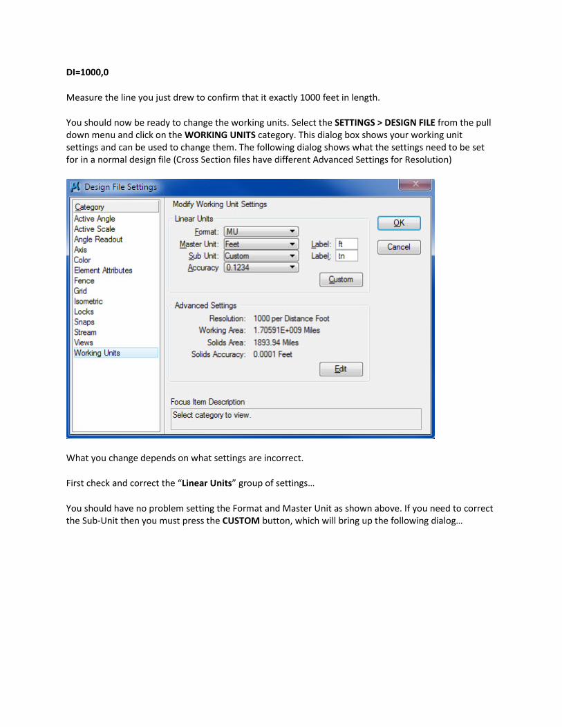
DI=1000,0
Measure the line you just drew to confirm that it exactly 1000 feet in length.
You should now be ready to change the working units. Select the SETTINGS > DESIGN FILE from the pull down menu and click on the WORKING UNITS category. This dialog box shows your working unit settings and can be used to change them. The following dialog shows what the settings need to be set for in a normal design file (Cross Section files have different Advanced Settings for Resolution)
What you change depends on what settings are incorrect.
First check and correct the “Linear Units” group of settings…
You should have no problem setting the Format and Master Unit as shown above. If you need to correct the Sub-Unit then you must press the CUSTOM button, which will bring up the following dialog…
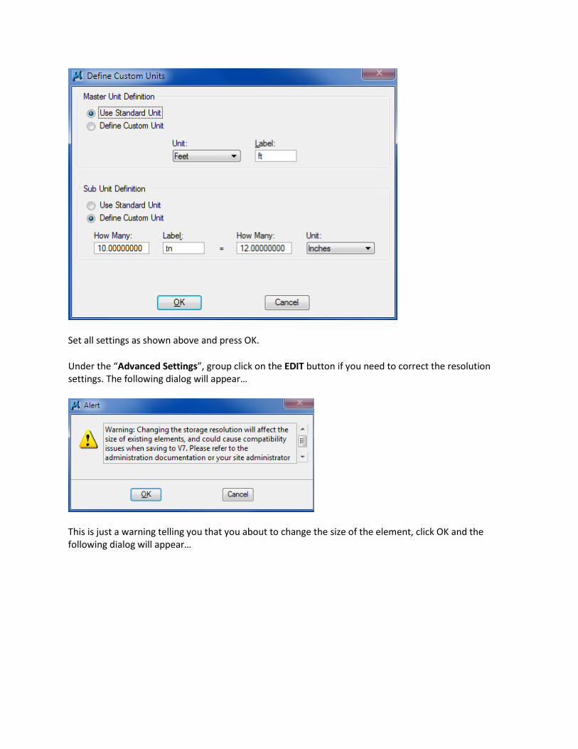
Set all settings as shown above and press OK.
Under the “Advanced Settings”, group click on the EDIT button if you need to correct the resolution settings. The following dialog will appear…
This is just a warning telling you that you about to change the size of the element, click OK and the following dialog will appear…
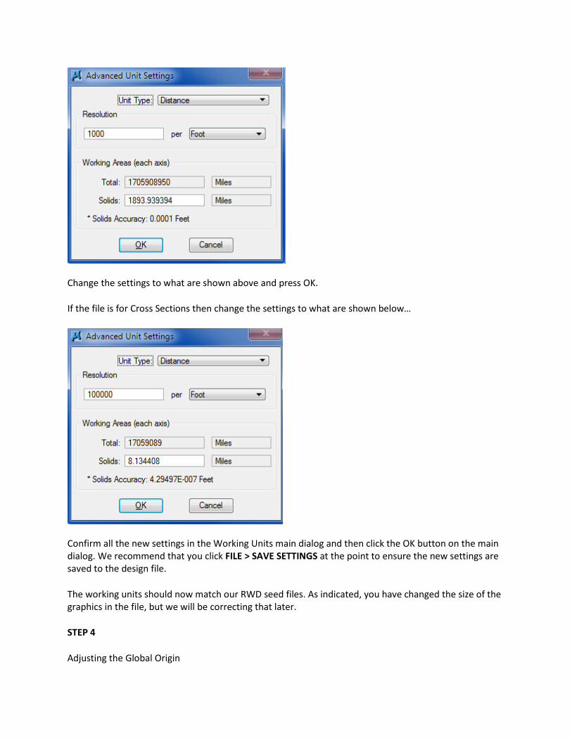
Change the settings to what are shown above and press OK.
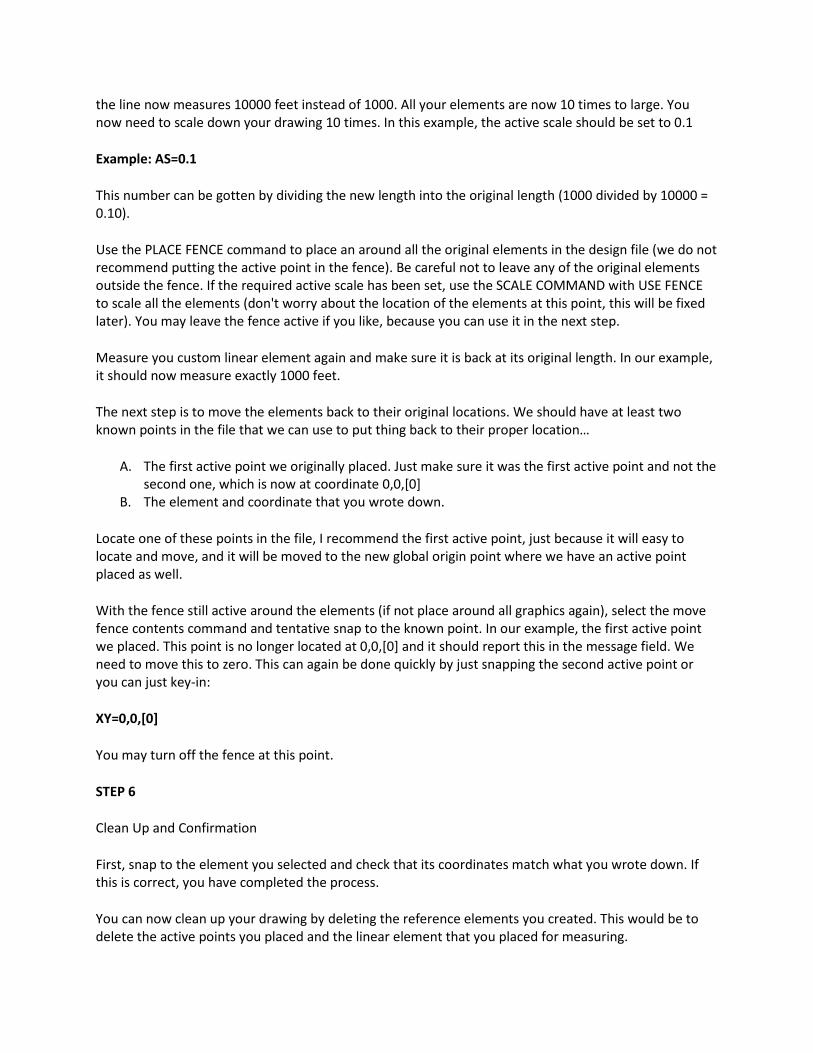
If the file is for Cross Sections then change the settings to what are shown below…
Confirm all the new settings in the Working Units main dialog and then click the OK button on the main dialog. We recommend that you click FILE > SAVE SETTINGS at the point to ensure the new settings are saved to the design file.
The working units should now match our RWD seed files. As indicated, you have changed the size of the graphics in the file, but we will be correcting that later.
STEP 4
Adjusting the Global Origin

With the working units adjusted, we now need to check and adjust where the global origin is located in the design file. We are not checking where coordinate 0 is located but rather its location in relationship to the entire design file plane. The global origin is the point in the file that reads as having the coordinate of 0, 0, [0]. If the file that you are adjusting has this point in the center of the design plane or some other variable location that does not match our RWD seed files, then it will have to be adjusted.
To check the global origin, key in the command GO=? and look at the status message to see what is reported. If the message indicated the origin being 0,0,[0] or any other numbers other than the following you will need to adjust the global origin.
RWD SEED File Global Origin Location [Viewed with key-in GO=?] should report the following values:
-2147483.6470, -2147483.6470
This next process assumes that the global origin is currently at the center of the file and reports being at the center of the design file at 0,0,[0]. (Note: if the global origin is not at the center of the design file and it reports any other coordinates other than what is shown in bold above, then you need to find where the center would be from those reported coordinate.)
You should already have an active point element placed a the coordinate 0,0,[0] ( If not, do so now). This point will help us locate where the proper global origin point need to be in the design. Place another active point by using this point as a reference by placing a tentative point on that location and then key-in the command:
dl=-2147483.6470, -2147483.6470
This key-in command will place another active point at a negative delta x,y distance from this original 0,0,[0] location. This establishes where the global origin should be located in RWD Seed Files.
If you tentative snap to the new active point it should currently report the values: -2147483.6470, -2147483.6470
Now you can key-in the command GO=0,0,[0] and select the last active point placed at the negative coordinates. This will move the global origin to the new location. If you tentative this point again, it should now report the coordinate is 0,0,[0].
You have now adjusted the global origin to match RWD seed files.
STEP 5
Correcting the Location of the Graphics
Scaling the Graphics
First, we will scale the elements back to their original size. Measure the line you drew earlier that was originally 1000 feet long. Use the length of this line to calculate what scale you need to use. Let suppose
the line now measures 10000 feet instead of 1000. All your elements are now 10 times to large. You now need to scale down your drawing 10 times. In this example, the active scale should be set to 0.1
Example: AS=0.1
This number can be gotten by dividing the new length into the original length (1000 divided by 10000 = 0.10).
Use the PLACE FENCE command to place an around all the original elements in the design file (we do not recommend putting the active point in the fence). Be careful not to leave any of the original elements outside the fence. If the required active scale has been set, use the SCALE COMMAND with USE FENCE to scale all the elements (don't worry about the location of the elements at this point, this will be fixed later). You may leave the fence active if you like, because you can use it in the next step.
Measure you custom linear element again and make sure it is back at its original length. In our example, it should now measure exactly 1000 feet.
The next step is to move the elements back to their original locations. We should have at least two known points in the file that we can use to put thing back to their proper location…
A. The first active point we originally placed. Just make sure it was the first active point and not the second one, which is now at coordinate 0,0,[0]
B. The element and coordinate that you wrote down.
Locate one of these points in the file, I recommend the first active point, just because it will easy to locate and move, and it will be moved to the new global origin point where we have an active point placed as well.
With the fence still active around the elements (if not place around all graphics again), select the move fence contents command and tentative snap to the known point. In our example, the first active point we placed. This point is no longer located at 0,0,[0] and it should report this in the message field. We need to move this to zero. This can again be done quickly by just snapping the second active point or you can just key-in:
XY=0,0,[0]
You may turn off the fence at this point.
STEP 6
Clean Up and Confirmation
First, snap to the element you selected and check that its coordinates match what you wrote down. If this is correct, you have completed the process.
You can now clean up your drawing by deleting the reference elements you created. This would be to delete the active points you placed and the linear element that you placed for measuring.
Font and Other Resource Problems
Some outside sources will use a different set of fonts than those used inside Roadway Design. If it becomes a necessity to be able use that drawing and/or plot the files, you will have to decide which procedure you need to correct the problem.
Procedure 1 - Edit the drawing files.
Probably the best solution for everyone involved would be to redo the drawing using RWD fonts. This however does require some work. If the design files are few and contain a limited amount of text, this would be the best choice because it totally eliminates this problem now and in the future, both in viewing and plotting.
Procedure 2 - Using a new set of source fonts
The next options is to obtain the source fonts for the drawing. This would require you to contact the source of the files and get them to send you their font resource files. This is not as easy as it may sound. You might have trouble finding the a person who is knowledgeable enough to know what you need and you will not know what to file to request. If you are able to get a copy of the source files, you will then have to have CADD support set up a local workspace that contains pointers to these source files. Doing this will allow you plot the file correctly, but the workspace will not be adequate to do any significant work on those files.
Dealing with 3D Files
It is very possible that the files you receive from outside sources have been done in 3D. There are several other civil software packages that require the use of 3D design files.
You could leave the files in 3D format, but you would probably find it very difficult to work with them. 3D work requires additional drawing skills and a knowledge of how to use these tools. In 3D, you always have to consider the Z axis. In many cases, the source users do not go a good job of drawing in 3D. Causing elements to be scattered up and down the Z axis. This creates problems fitting views, measuring and calculating quantities, referencing other design files and many other problems.
The easiest most reasonable solution to this is to convert the files to 2D. This is done with the File>Export>2D command. This process flattens all the elements into a 2D file.
One thing to consider when exporting 3D to 2D is that you can save the Z axis data in the design file in case you want to convert it back to 3D later.
Another issues you may have to deal with during conversions is file naming. To retain the original drawing you need to put it in a separate directory from your project or rename either the original or the 2D version of the file. This normally would not be a problem, except the file may have references

attached. If this is the case, renaming the files would create a problem. This is because the reference file attachments would be lost during the renaming process.
One solution to this is to rename all the files and then rename them back to the original names during the conversion process. If your think of taking a shortcut by eliminating the originals - Don't, you may need them later, especially if something goes wrong.
Always check the original 3D drawing for attached references before converting them to 3D. Make a list of the attached files, because you may need to convert them also. You can now reference a 3D files to a 2D file. This means that you could leave some files 3D and still have them referenced to other files (i.e. a sheet design). It just a decision you need to make regarding how you plan on using the files. If you just want to plot them, you might want to leave them 3D. If you plan to edit, measure, etc. you probably would want to convert them to 2D.
When converting a file to 2D, you have to indicate which view to translate. The view must also show the elements you are converting. Most of time you would be do a TOP view. If this is true, then you should make sure you are selecting a view that is not rotated and has been set to a top view (vi=top). You should also make sure the display depth is large enough to make all the elements show up and make sure all levels are showing that you wish to convert.
Locks
Locks in Microstation allow you to hold certain settings. An example would be the Axis Lock. This locks in angles when doing MicroStation commands. By default, this lock allows you to modify or move an element in one of the four, 90 degree directions. This is a handy tool, but can hinder you from doing other things. This can also be the case with the other locks as well.
You can have problems working with the elements, as you would normally expect if some of these locks are on. By default, in Roadway Design dgn files, we only have SNAP LOCK > KEYPOINT on. All others are turned off by default.
If you are working and don't get the results that you expect when adding or modifying elements. You should check the lock settings. The quickest way to see all the lock settings is to select SETTINGS > LOCKS > FULL dialog box. Uncheck any that shouldn't be on.
Dimension Elements
On a normal highway project in Roadway Design, you may never have to use dimension elements. If you have to deal with a file that has dimension elements or wish to use them, you should be aware of certain things. Dimension elements are handled different from other normal elements. A dimension elements appearance and characteristics are controlled separately.
If you bring up the ELEMENT > DIMENSION STYLES dialog box you will see a variety of settings that control dimension elements. By default, none of these setting have been preset for you. If you plan on using dimension settings or need to check what someone else used, this is the dialog box you want to look at.
I recommend that you don't use dimension elements. If you decide you want to use them, it will be necessary for you to configure the settings.
Here are some things that you should be aware of:
1. Don't use system SYMBOL fonts for any of the custom symbols or terminator symbols. Use either default or cells. Symbols only plot correctly if you have the proper resource files attached to the design file. We currently do not support any symbol resource files.
2. Don't try not to use any color, style, or weight overrides. The purpose of these are to set them different than active settings. The problem with these settings is that you can't change the dimension element unless you change them in the dialog (which changes all of them) or you can drop the dimension elements and then change them.
3. These settings can also override basic text sizes. If you set them in the dialog, you have to determine the correct size for the drawing you’re working with and change them in other design files as well.
4. Dimension settings can change from one design file to the next. When dimension settings are made, they don't carry over to the next design file. A design library (in essence a seed file) could be created with certain custom dimension settings, which can be attached to other design files.
If you get a file that has dimension elements in it, you can check the dimension elements dialog to change their appearance or you can use the Drop Dimension command to make them normal elements. If someone has used symbols for terminators, you will need to replace them. The only option in this case, is to drop them and replace the symbols with a cell.
Misc. Design File Settings
If you select SETTING > DESIGN FILE it will bring up a dialog box that shows all the internal default settings for the design file. These settings control the default active angle, scale, colors, locks, coordinate readout, snaps, stream, views, and working units. I recommend that you NEVER change these, unless someone has set them incorrectly. The correct settings for all these have been documented in the CADD Manual/Help files.
Some of the settings, when changed, will not have a drastic effect on the file, but some do. Below I will point out some problems you may have and how to correct them.

1. Active Angle, Scale : only sets the default angle or scale when entering a design file. Will not affect you work if changed, but check to see if the locks are turned on. They should be off.
2. Axis, Fence, Grid, and Isometric should be off by default.
3. Coordinate Readout should be in Master Units and Angles in DD MM SS (Mode: Conventional). Changing them will not change the design file, but can affect the way you see readout of measurements. It also can affect the way you enter angle directions if not set to conventional mode.
4. Working Units should be set as documented in the CADD Manual. If they are different, you will need to correct them. Changing this setting will drastically change the drawings dimensions and location. See the working units topic in this document for information on how to fix working units.
Customizing Microstation
Everyone has an opinion. The good and bad thing about opinions is that people can have a different one. What I have learned about customizing Microstation is to make it as generic as possible, but also have them set the way we like to work in Roadway Design. We never try to customize based on personal preferences, but rather what we think the overall group needs. We also allow users to customize their preferences to suit their own "opinion".
When it comes to Microstation, you can be satisfied with the way CADD support has set up the preference and interface or you can add to it by creating your own items. Many hours have been spent working on the configuration to make sure everything works together. We will always do the best we can to make sure that it does, but If you think it doesn't work well, then let us know and we will definitely try to fix it.
When a user customizes Microstation, they have the luxury of making it work for very specific functions. One problem with this is that you may have to change it for the next project. This is perfectly fine to do, but only if it makes your job easier and doesn't take too long to accomplish. If your customization takes too long to set up and has to be changed all the time, then It might be more of an advantage if you never did it at all. You have to balance the time it takes to make the customizations with the result that it achieves.
The problem that occurs with personal customizations is the user may not fully understand how to create them. If you choose to customize, you should spend the time necessary to learn the process. If this is not done you may end up creating something that is counter-productive.
You own customization, from the stand-point of support is as a luxury, not a necessity. I do not wish to discourage a user from customizing, but when you do, you should be able to undo your changes if something goes wrong. Always attempt to clean-up your own mistakes. Doing so, will help you to learn the proper way of customizing.
In this document you can find several topics on the customization tool boxes, cell libraries, function keys, etc. These topics are listed below, click on them to go directly to them:
User Interface (Custom Tool Palettes) Creating Cell Libraries Function Key Menus Preference and Workspace Tweaks
User Interface (Custom Tool Boxes and Task)
For a quick summary of creating a custom interface, click here.
For a more detail overview, continue reading...
Custom User Interfaces are much easier in Microstation that in previous versions, but still has the potential to cause problems for the user and the support team. If you decide you want to create your own custom tool boxes, task bars, etc. Please go over the following processes in detail, this should help you avoid problems.
Note: This procedure follows customization in the V8i versions of Microstation. The customization tools for earlier versions are no longer documented.
1. The first thing you should know about custom tool boxes is that the tools you create and modify are not changing the Microstation tools themselves. The changes are actually saved in a separate dgnlib file that will override Microstation's defaults. If you corrupt, lose, or move this file then Microstation reverts back to its' standard tools. This file is currently located under whatever is the current Microstation default interface folder. This directory has sub-directories under it. The sub-directory names are what you select as your interface name when entering Microstation. There are usually several default interfaces to select from, but Roadway Design creates its own, a sub-directory called RWD is created to hold our interface file.
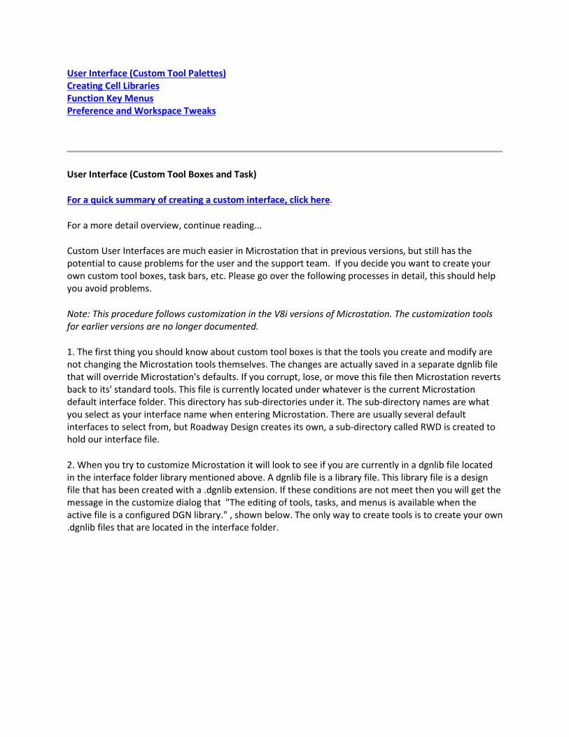
2. When you try to customize Microstation it will look to see if you are currently in a dgnlib file located in the interface folder library mentioned above. A dgnlib file is a library file. This library file is a design file that has been created with a .dgnlib extension. If these conditions are not meet then you will get the message in the customize dialog that "The editing of tools, tasks, and menus is available when the active file is a configured DGN library." , shown below. The only way to create tools is to create your own .dgnlib files that are located in the interface folder.
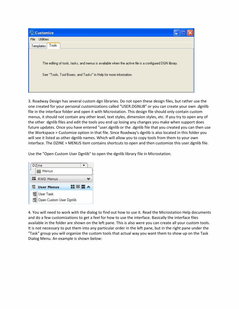
3. Roadway Design has several custom dgn libraries. Do not open these design files, but rather use the one created for your personal customizations called "USER.DGNLIB" or you can create your own .dgnlib file in the interface folder and open it with Microstation. This design file should only contain custom menus, it should not contain any other level, text styles, dimension styles, etc. If you try to open any of the other dgnlib files and edit the tools you end up losing any changes you make when support does future updates. Once you have entered "user.dgnlib or the .dgnlib file that you created you can then use the Workspace > Customize option in that file. Since Roadway's dgnlib is also located in this folder you will see it listed as other dgnlib names. Which will allow you to copy tools from them to your own interface. The DZINE > MENUS item contains shortcuts to open and then customize this user.dgnlib file.
Use the "Open Custom User Dgnlib" to open the dgnlib library file in Microstation.
4. You will need to work with the dialog to find out how to use it. Read the Microstation Help documents and do a few customizations to get a feel for how to use the interface. Basically the interface files available in the folder are shown on the left pane. This is also were you can create all your custom tools. It is not necessary to put them into any particular order in the left pane, but in the right pane under the "Task" group you will organize the custom tools that actual way you want them to show up on the Task Dialog Menu. An example is shown below:
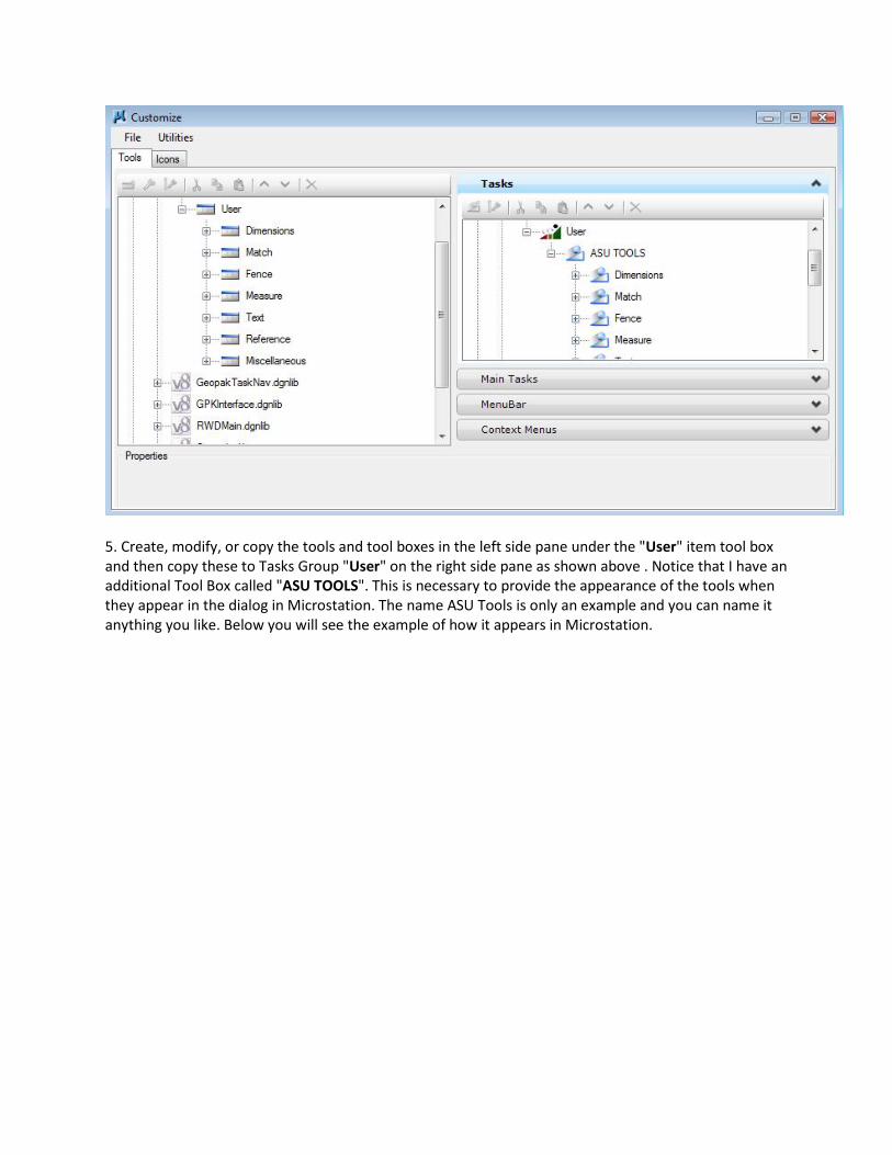
5. Create, modify, or copy the tools and tool boxes in the left side pane under the "User" item tool box and then copy these to Tasks Group "User" on the right side pane as shown above . Notice that I have an additional Tool Box called "ASU TOOLS". This is necessary to provide the appearance of the tools when they appear in the dialog in Microstation. The name ASU Tools is only an example and you can name it anything you like. Below you will see the example of how it appears in Microstation.
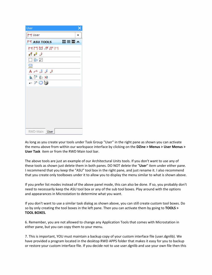
As long as you create your tools under Task Group "User" in the right pane as shown you can activate the menu above from within our workspace interface by clicking on the DZine > Menus > User Menus > User Task item or from the RWD Main tool bar.
The above tools are just an example of our Architectural Units tools. If you don't want to use any of these tools as shown just delete them in both panes. DO NOT delete the "User" item under either pane. I recommend that you keep the "ASU" tool box in the right pane, and just rename it. I also recommend that you create only toolboxes under it to allow you to display the menu similar to what is shown above.
If you prefer list modes instead of the above panel mode, this can also be done. If so, you probably don't need to necessarily keep the ASU tool box or any of the sub tool boxes. Play around with the options and appearances in Microstation to determine what you want.
If you don't want to use a similar task dialog as shown above, you can still create custom tool boxes. Do so by only creating the tool boxes in the left pane. Then you can activate them by going to TOOLS > TOOL BOXES.
6. Remember, you are not allowed to change any Application Tools that comes with Microstation in either pane, but you can copy them to your menu.
7. This is important, YOU must maintain a backup copy of your custom interface file (user.dgnlib). We have provided a program located in the desktop RWD APPS folder that makes it easy for you to backup or restore your custom interface file. If you decide not to use user.dgnlib and use your own file then this
application will not work for you. See the chapter on RWD APPS for details instructions on how to your the BackUp/Restore program. REMEMBER THAT THE CUSTOM INTERFACE FILE IS YOUR FILE, NOT OURS, SO BACK IT UP!!!
8. When new versions of Microstation are installed on your computer, don't always expect your interface customization to work in the new version. Roadway's tool are very likely to change with each new version of Microstation, so don't get upset if your custom tools stop working. If support installs or updates the RWD Menus and Interfaces you WILL lose your custom tools, but this may only be temporary if you have created a backup of your edits. Just use the application described in the above step to RESTORE it. This is why it is so important for you to back up.
9. You can access your custom tools from both the DZine menu under DZINE > MENUS > USER TASK or by keying in the command "tasktoolbox open user".
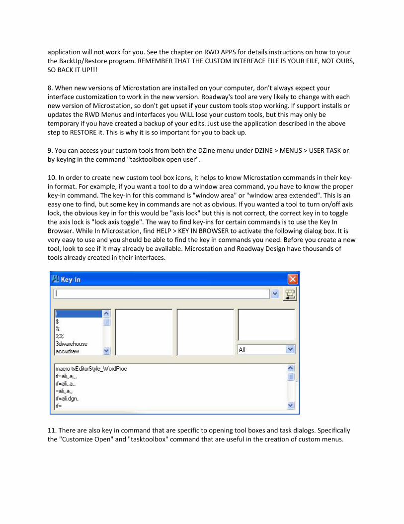
10. In order to create new custom tool box icons, it helps to know Microstation commands in their key-in format. For example, if you want a tool to do a window area command, you have to know the proper key-in command. The key-in for this command is "window area" or "window area extended". This is an easy one to find, but some key in commands are not as obvious. If you wanted a tool to turn on/off axis lock, the obvious key in for this would be "axis lock" but this is not correct, the correct key in to toggle the axis lock is "lock axis toggle". The way to find key-ins for certain commands is to use the Key In Browser. While In Microstation, find HELP > KEY IN BROWSER to activate the following dialog box. It is very easy to use and you should be able to find the key in commands you need. Before you create a new tool, look to see if it may already be available. Microstation and Roadway Design have thousands of tools already created in their interfaces.
11. There are also key in command that are specific to opening tool boxes and task dialogs. Specifically the "Customize Open" and "tasktoolbox" command that are useful in the creation of custom menus.
12. The customize tool will also allow you to edit the "MenuBar" pulldown items. We do not recommend that this be done, but you may want to add some "Context Menus" items. This allows you to create tools on the menu that is displayed when you hold down the reset button on the mouse.
Summary of Creating Custom Tools:
These steps are a summary of creating custom tools in Roadway Design Interface.
1. Open this custom dgnlib design file with Microstation and click on Workspace > Customize. You can open the user.dgnlib file from within Microstation from the DZine Menu, MENUS > USER MENUS > OPEN CUSTOM USER DGNLIB
3. Just above the left-side window pane click on the TOOLS tab.
4. Under User Tools, locate USER.DGNLIB and create your tools under the User item. You do not have to organizer your tools under this left-side window pane, but try to use tool names that do not already existing in the Task Navigation Menu. You can create both tools and tool boxes. Tool boxes hold tools.
5. Above the right-side window pane you can select TASKS and under this select the User Tasks Item in the right-side window pane. Copy the tools you created in the left-pane under USER.DGNLIB + User to the right-side window pane under the same name. This makes your tools show up as a TASK DIALOG menu in Microstation. Organize the tools in the right-side window pane the way you wish them to show up on the task navigation menu. All tool boxes that you create on the left-side window pane will show up under the option TOOLS > TOOL BOXES on the main Microstation tool menu. You are not required to copy your custom toolboxes to the right pane. The best way to learn how the panes work is to practice and see the results.
6. Save a backup copy of USER.DGNLIB file if you wish to have access to it in the future. You can use the program available in the RWD APPS desktop folder to do both a backup copy and restore it.
Creating Cell Libraries
Most users cells are very specific, so they can't be used in the general cell library, but I highly recommend that you create your own libraries to use for yourself. When you make your own cells and put them in a library, the same common mistakes are usually made. Below I listed some of them and what you should do to avoid them.
1. Create cells in the same design file working units as the design file you will placing them in. If you don't, you have to spend a lot of unnecessary time adjusting the placement scale or you have to always use the "true scale" feature when you place your cells . I create most cells at 1:1 scale. This means that you can set the active scale to the plotting scale when placing it. By doing this, cells will plot to the correct size. See CELLS Chapter for more information on this. When creating a cell, try and make its origin point at a location that will provide the best ease of placement. For example, if you cell is most often placed in the upper-right corner of a plan sheet, you should make its origin in the upper-right corner.
2. Create your cells on the proper levels. Set your levels based on the standard level setup used in Roadway Design.
3. Another common mistake is creating cells inside of cells (called nested cells). This happens a lot when user makes a cell out of a sheet. A good example is a typical section sheet. It commonly contains cells all over the sheet (arrow heads, circles with numbers, etc.). Even though Microstation will let you create nested cells, it is not a good idea. In certain scenarios, you will corrupt the cell or design file the cell is placed in. You need to drop all the cells in your drawing before you make a cell out of it.
4. This does not fall under the topic of cell creation, but it is a mistake that some have made. In the cell dialog box, an option for "Use Shared Cells" exist that should NEVER be turned on. The purpose of this is to decrease the size of your design file. It works by only placing one cell in your file. If that cell is placed again it is not really placed, but is only a ghost image of the first cell. Using shared cells causes problems when the cell is used by others or modifications of the cells in the design file is required.
5. In the case of cells, many users want to create enter-data fields to be part of the cell. This allows them to input text that changes depending on what the cell is being used for. Below is an overview of how to create data fields:
Set you text parameters, then use the Place Text command. A data-field character is then created by pressing the underbar ( _ ) key for each text character you want in that data-field. The underbar character is usually located on the keyboard above the dash character. When you place a data-field in the design file you have to turn on the view attribute "data field" item to see them. This is off by default in our seed file. You can also justify the data fields and make the inputted text either shift left, center, or shift right when filled in. The commands to justify data fields are included on the text tool box when using the RWD interface. Justify the data fields before filling them in.
6. Cell libraries can be attached via the Cell Dialog box, but they can also be attached with the key-in "rc=". When using this key-in, Microstation will only look in your current directory or the default RWD group directory. This is due to the configuration settings. I recommend that you place a copy of the cell library in the project directory were you are using them. Not only does this make it more convenient for you to attach, but it also preserves these cells for future work that may be done on this project.
Function Key Menus
One very useful customization tool in Microstation are the Function Key Menus. On the top of your keyboard there are 12 keys, always labeled F1, F2, F3, etc. These keys can be programmed in Microstation to run commands. This section will discuss how you can customize these keys.
Before we discuss the creation of a function key menu, let’s go over a few items that you should know before-hand.
Roadway Design's current configuration files (.ucf) specifies that the function menu c:\rwd\group\rwdfunkey.mnu be used as the default menu. This menu has the keys pre-set to functions
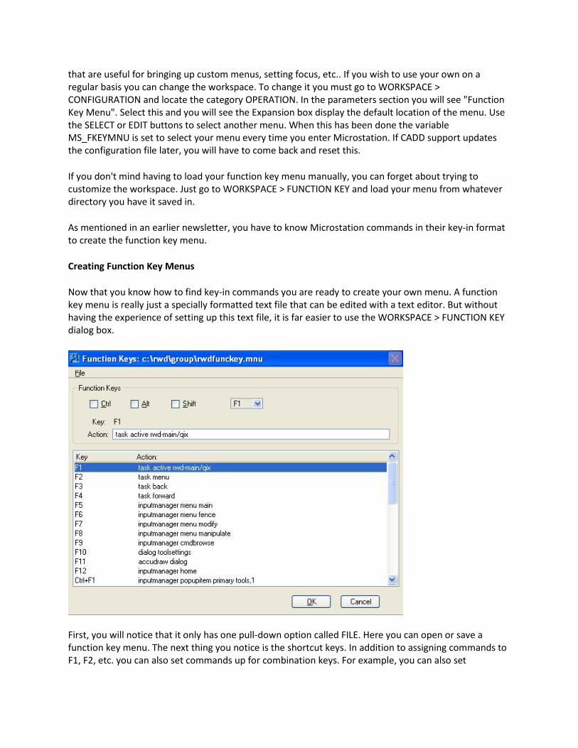
that are useful for bringing up custom menus, setting focus, etc.. If you wish to use your own on a regular basis you can change the workspace. To change it you must go to WORKSPACE > CONFIGURATION and locate the category OPERATION. In the parameters section you will see "Function Key Menu". Select this and you will see the Expansion box display the default location of the menu. Use the SELECT or EDIT buttons to select another menu. When this has been done the variable MS_FKEYMNU is set to select your menu every time you enter Microstation. If CADD support updates the configuration file later, you will have to come back and reset this.
If you don't mind having to load your function key menu manually, you can forget about trying to customize the workspace. Just go to WORKSPACE > FUNCTION KEY and load your menu from whatever directory you have it saved in.
As mentioned in an earlier newsletter, you have to know Microstation commands in their key-in format to create the function key menu.
Creating Function Key Menus
Now that you know how to find key-in commands you are ready to create your own menu. A function key menu is really just a specially formatted text file that can be edited with a text editor. But without having the experience of setting up this text file, it is far easier to use the WORKSPACE > FUNCTION KEY dialog box.
First, you will notice that it only has one pull-down option called FILE. Here you can open or save a function key menu. The next thing you notice is the shortcut keys. In addition to assigning commands to F1, F2, etc. you can also set commands up for combination keys. For example, you can also set
commands to work when you press CTRL F1, ALT F1, and SHIFT F1. In essence allowing you to create up to 48 (4 x 12) different commands on the function keys.
Now all you have to do to assign the command is to select the shortcut and key and use the EDIT or DELETE buttons.
When you select the EDIT button you are given a box that shows the button keys you are setting and a place where you can assign a command. Just do this for all the keys you want to set up and save it to a new file or the current file.
With the menu created you can use it any time by either manually attaching it or by using one of the methods mentioned early to automatically attach it when you enter Microstation.
The biggest disadvantaged to function key menus is that it can be difficult to remember which keys do what command. The solution to this problem has been around for long time and I have seen them used many times with word processing programs. The solution is to create a drawing that can be taped or placed around the function keys that label what each button does. With a few measurements you could draw and plot a graphic that can be taped above the function keys. Microstation is a perfect tool for creating this.
Preference and Workspace Tweaks
Roadway has created a Microstation preference and workspace files that can and should be used when working on MDOT projects. In most cases these files are sufficient for creating an environment that is very productive to our working standards.
Preference File
The preference file (.upf) is used to set Microstation preference is geared to work well in Roadway Designs environment. It makes overall settings on how Microstation will act when placing text, referencing, how the GUI looks, weather you are using a two or three button mouse, and its saves the location of opened dialogs and tools, among other things.
Roadway Design has created a default preference file which is located in group directory. Our workspace (which will discussed below) has been set to copy this file when it has to create a new preference file. It is uniquely set up to function with our hardware and software standards.
NOTE: Preference Corruptions: The preference file is a binary resource file that can't be "fixed" if it gets corrupted. This file is being constantly written to. Think about how many times you move tools and dialogs. Every time you do this the preference file is modified to "remember" its new location. You probably now will realize that the chances for this file to get "hosed" becomes more likely. It does and will happen. The only way to fix this file is to delete it and let Microstation create a new one. The worst part of this is you have to go back and reset all changes from that are different than the default. I suggest that you set up you basic preference like you want and save the (.upf) file somewhere, so that that it can be reused in those situations.
You could alter our workspace to open a different preference template, or you can modify ours to suit your needs. I have listed and explained below some items that you could change without causing adverse conditions.
Workspace > Preferences
Look and Feel 1. Default Tool : Some like this set to SELECTION, some like to set this to NONE. When selection is on, every time Microstation does not know what command to activate, it will default to the "element selection" tool. Some find this bother-some because they do no use element selection as often as others. The default is SELECTION, because this mode is required when using some third-party applications. If you do turn it to NONE, you may at some point have to turn it back on. 2. Auto-Focus Tool Settings: By default this is on. We turn it off because users tend to use the key-in window more often. When this is on the focus always jumps to the tools window causing key-in entries in the wrong place.
Operation 1. Open Two Application Windows: This is usually off by default in the untitled workspace, but we turn it on because it works better when using two monitors. With two windows you don't have to worry about the window being split down the center and it gives you more places to dock tools. If you have only one monitor you will need to turn this off. 2. Save Settings on Exit: This is off by default so we turn it on. We prefer the active settings to be saved so that when you re-enter they are the same as when you exited. 3. Compress File on Exit: This is off by default and you should leave it off. This removes deleted elements from the file when you exit. Since you can't restore elements after it is compress we leave it off. 4. Optimized Fence Clipping: This is on by default and we leave it on, but there may be times you want to turn it off. What this does is it maintains closed shapes even when they are clipped rather than dropping them to linear elements. 5. Resource and Font Cache: The default size of these are okay in most cases, but you may want to increase them. The trade-off depends on how much memory you have on your system. Raising the values will take away from your overall system resources but will enhance the speed of Microstation. Most systems today can handle an increase if you don't run a lot of applications all at one time. I have double these values with no ill-effect.
Position Mapping 1. Use Position Mapping: This feature was added in XM Microstation and allows you to use the keyboard letter to select command icons. The up-side to this is you can gain an increase in speed of selecting commands. The down-side is that an additional "focus" is created for the keyboard. This default focus is called "home" focus. This can be difficult to get accustomed to if you like key in focus to be the default. This is on by default, but user seem to prefer it off. Note that if you set it on, you can use the F9 key to quickly jump to Key In focus. 2. Show Position Mapping Aids: This will display letters on the tools making it easier to learn or see which keyboard letter is assigned to an icon. They can be useful, but block out a large portion of the icons. This have been changed to be off in our preferences. The "Use Position Mapping" option has to be on to change this setting.
Raster Manager In this section, you can greatly effect what happens when you attach raster files as references. Some
you definitely want to turn on and some you definitely want to turn off, depending on what kind of raster file your using. If you using any kind of georeference raster file you should go to that tab and set the preferences appropriately.
Under Microsation V8i the "Georeference" tab, Sister File Settings should be set to on. The Default Unit Settings need to be FEET. This setting is currently need to allow our county .sid files to reference properly. If you use TerraShare, then it needs to be set to METERS. Reference You should turn ON the "Remap Colors on Copy". This will insure that when you copy elements from a reference file that has different colors to be remapped to standard colors. Make sure that you DO NOT turn ON Nesting. Leave it set to "No Nesting" to conform to Roadway's standards.
Text Text Editor Style: The Roadway Design default for this is "Word Processor". This is not necessarily what most of Roadway Design users prefer, but the "Key In" mode no longer functions properly.
Workspace > Button Assignments
Button Assignments The button assignments established in Roadway Design workspace to always be set to work with a 3-button mouse. 3 button mouse were not always common, but because we always had them, we set the middle button as a manual tentative button. The wheel-mouse is now common and allows for a middle button to be available to everyone. The default workspace delivered with Microstation abandoned the manual tentative button and assigned the middle mouse wheel to do other commands (i.e. pan drag) and assumes that everyone will use the AccuSnap feature. Neither of these are common practice in Roadway Design so the middle wheel button press will remain a manual tentative button. If you have access to a 4 or 5 button mouse the pan drag command will be assigned to button 4.
Configuration File
The configuration file (.ucf) is the key ingredient in how Microstation will act. It contains all the Microstation "environment variables" that point to key files. These key files are cells, programs, seed files, etc. They need to be located in the default workspace users folder to function.
In order for Microstation to see all the data files Roadway Design has created we have created a workspace file that you MUST use while working on MDOT projects. Without it you would have a very difficult time working.
We actually have several workspace files, one for metric and two for English (east and west zones). They work basically the same, but each points to a different set of data files, located in different directories. These data directories are standard folders created under the C drive of your computer. The main directory is called RWD and the sub-directories under it are the folders that contain the data. Some data is for Microstation and some is for Geopak. If this data was loaded on your computer based on standard instructions, the workspaces will be able to find what it needs to point Microstation to this data.
When entering Microstation using the Microstation Manager box you can select one of our workspaces in the Workspace > User field. If the proper workspace is selected a design file will open with the data, menus, and settings all in place to work on MDOT projects.
The configuration file (.ucf) is a normal ASCII file that contains environment variable. There are too many to list here, but if you open the file you can decipher the meaning of all the settings or even better is to use the WORKSPACE > CONFIGURATION menu item to pull up the dialog interface. Here you can get a short description of what each variable can do for you.
You basically should NOT change the variables set in Roadway's workspace, unless you really know what you are doing. It is okay to change some of the others that haven't been set, but again you should be sure about what your changing. Some serious problems can occur if you are not careful. Then again; if you botch it up too much, you can re-copy the template configuration files from the group directories.
NOTE: If you ever want an environment variable to point to the same directory as the design file is located in, set the value to equal to = $(_dgndir)
Below I have listed some additional variables that can be changed and the effects that are gained or lost:
AccuDraw Shortcuts: MS_ACCUDRAWKEY We prefer precision key ins in the key in field, but if you like AccuDraw, you might find it helpful to change the shortcut keys that it uses. This variable points to the text file that has the shortcuts. I would change the standard, but you can copy the text file, change it, and put it in another directory. Then change this variable to point to it.
Archiving: MS_ARCHIVE Microstation has a very nice archiving tool. It has the built-in ability to save a design file and automatically bring along any supporting files that go with it, such as; reference files, resources, etc. The only disadvantage is that you have to have Microstation to restore it. This variable points to the same folder as your active design file.
Backups: MS_BACKUP When using the "backup" command a copy of your design file is created with a default extension (.bak). The location can be set for the backup with this variable. This variable points to same folder as your active design file.
Reference Full Path: MS_DISALLOWFULLREFPATH Using the full path to attach a reference is never a good way to work. Microstation can remember the full path but if you move directories or share your files, it will cause major problems. You can activate this variable, thus making it impossible to attach the reference unless it is in the same directory as the current dgn file.
User Command on Exit: MS_EXIT If you can write a user command and you need something done each time you exit the design file this variable can do that for you. Just point it the user command that you want to run.
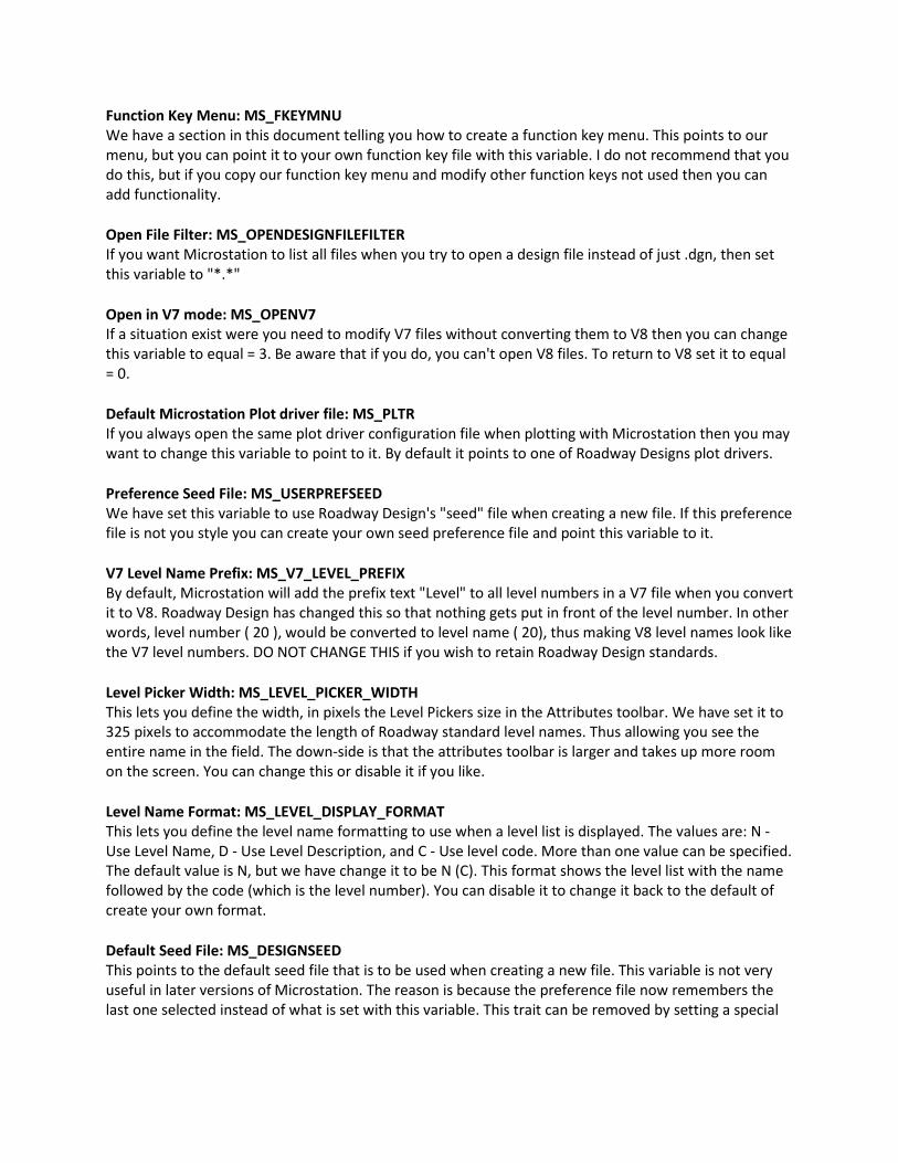
Function Key Menu: MS_FKEYMNU We have a section in this document telling you how to create a function key menu. This points to our menu, but you can point it to your own function key file with this variable. I do not recommend that you do this, but if you copy our function key menu and modify other function keys not used then you can add functionality.
Open File Filter: MS_OPENDESIGNFILEFILTER If you want Microstation to list all files when you try to open a design file instead of just .dgn, then set this variable to "*.*"
Open in V7 mode: MS_OPENV7 If a situation exist were you need to modify V7 files without converting them to V8 then you can change this variable to equal = 3. Be aware that if you do, you can't open V8 files. To return to V8 set it to equal = 0.
Default Microstation Plot driver file: MS_PLTR If you always open the same plot driver configuration file when plotting with Microstation then you may want to change this variable to point to it. By default it points to one of Roadway Designs plot drivers.
Preference Seed File: MS_USERPREFSEED We have set this variable to use Roadway Design's "seed" file when creating a new file. If this preference file is not you style you can create your own seed preference file and point this variable to it.
V7 Level Name Prefix: MS_V7_LEVEL_PREFIX By default, Microstation will add the prefix text "Level" to all level numbers in a V7 file when you convert it to V8. Roadway Design has changed this so that nothing gets put in front of the level number. In other words, level number ( 20 ), would be converted to level name ( 20), thus making V8 level names look like the V7 level numbers. DO NOT CHANGE THIS if you wish to retain Roadway Design standards.
Level Picker Width: MS_LEVEL_PICKER_WIDTH This lets you define the width, in pixels the Level Pickers size in the Attributes toolbar. We have set it to 325 pixels to accommodate the length of Roadway standard level names. Thus allowing you see the entire name in the field. The down-side is that the attributes toolbar is larger and takes up more room on the screen. You can change this or disable it if you like.
Level Name Format: MS_LEVEL_DISPLAY_FORMAT This lets you define the level name formatting to use when a level list is displayed. The values are: N - Use Level Name, D - Use Level Description, and C - Use level code. More than one value can be specified. The default value is N, but we have change it to be N (C). This format shows the level list with the name followed by the code (which is the level number). You can disable it to change it back to the default of create your own format.
Default Seed File: MS_DESIGNSEED This points to the default seed file that is to be used when creating a new file. This variable is not very useful in later versions of Microstation. The reason is because the preference file now remembers the last one selected instead of what is set with this variable. This trait can be removed by setting a special
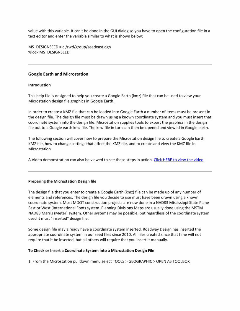
value with this variable. It can't be done in the GUI dialog so you have to open the configuration file in a text editor and enter the variable similar to what is shown below:
MS_DESIGNSEED = c:/rwd/group/seedeast.dgn %lock MS_DESIGNSEED
Google Earth and Microstation
Introduction
This help file is designed to help you create a Google Earth (kmz) file that can be used to view your Microstation design file graphics in Google Earth.
In order to create a KMZ file that can be loaded into Google Earth a number of items must be present in the design file. The design file must be drawn using a known coordinate system and you must insert that coordinate system into the design file. Microstation supplies tools to export the graphics in the design file out to a Google earth kmz file. The kmz file in turn can then be opened and viewed in Google earth.
The following section will cover how to prepare the Microstation design file to create a Google Earth KMZ file, how to change settings that affect the KMZ file, and to create and view the KMZ file in Microstation.
A Video demonstration can also be viewed to see these steps in action. Click HERE to view the video.
Preparing the Microstation Design file
The design file that you enter to create a Google Earth (kmz) file can be made up of any number of elements and references. The design file you decide to use must have been drawn using a known coordinate system. Most MDOT construction projects are now done in a NAD83 Mississippi State Plane East or West (International Foot) system. Planning Divisions Maps are usually done using the MSTM NAD83 Marris (Meter) system. Other systems may be possible, but regardless of the coordinate system used it must "inserted" design file.
Some design file may already have a coordinate system inserted. Roadway Design has inserted the appropriate coordinate system in our seed files since 2010. All files created since that time will not require that it be inserted, but all others will require that you insert it manually.
To Check or Insert a Coordinate System into a Microstation Design File
1. From the Microstation pulldown menu select TOOLS > GEOGRAPHIC > OPEN AS TOOLBOX
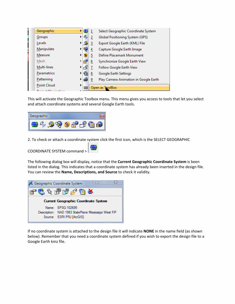
This will activate the Geographic Toolbox menu. This menu gives you access to tools that let you select and attach coordinate systems and several Google Earth tools.
2. To check or attach a coordinate system click the first icon, which is the SELECT GEOGRAPHIC
COORDINATE SYSTEM command >
The following dialog box will display, notice that the Current Geographic Coordinate System is been listed in the dialog. This indicates that a coordinate system has already been inserted in the design file. You can review the Name, Descriptions, and Source to check it validity.
If no coordinate system is attached to the design file it will indicate NONE in the name field (as shown below). Remember that you need a coordinate system defined if you wish to export the design file to a Google Earth kmz file.
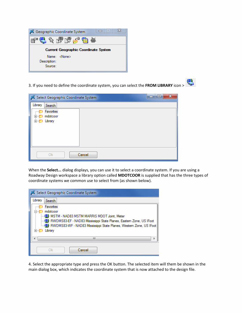
3. If you need to define the coordinate system, you can select the FROM LIBRARY icon >
When the Select... dialog displays, you can use it to select a coordinate system. If you are using a Roadway Design workspace a library option called MDOTCOOR is supplied that has the three types of coordinate systems we common use to select from (as shown below).
4. Select the appropriate type and press the OK button. The selected item will them be shown in the main dialog box, which indicates the coordinate system that is now attached to the design file.
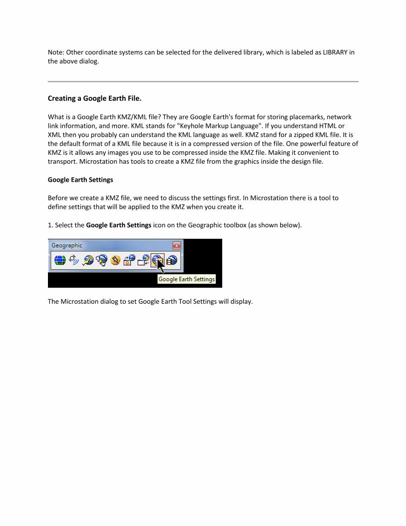
Note: Other coordinate systems can be selected for the delivered library, which is labeled as LIBRARY in the above dialog.
Creating a Google Earth File.
What is a Google Earth KMZ/KML file? They are Google Earth's format for storing placemarks, network link information, and more. KML stands for "Keyhole Markup Language". If you understand HTML or XML then you probably can understand the KML language as well. KMZ stand for a zipped KML file. It is the default format of a KML file because it is in a compressed version of the file. One powerful feature of KMZ is it allows any images you use to be compressed inside the KMZ file. Making it convenient to transport. Microstation has tools to create a KMZ file from the graphics inside the design file.
Google Earth Settings
Before we create a KMZ file, we need to discuss the settings first. In Microstation there is a tool to define settings that will be applied to the KMZ when you create it.
1. Select the Google Earth Settings icon on the Geographic toolbox (as shown below).
The Microstation dialog to set Google Earth Tool Settings will display.
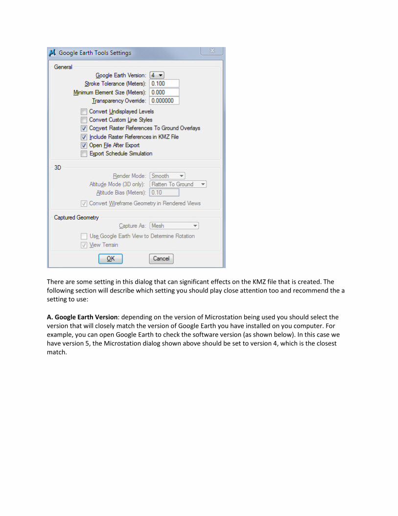
There are some setting in this dialog that can significant effects on the KMZ file that is created. The following section will describe which setting you should play close attention too and recommend the a setting to use:
A. Google Earth Version: depending on the version of Microstation being used you should select the version that will closely match the version of Google Earth you have installed on you computer. For example, you can open Google Earth to check the software version (as shown below). In this case we have version 5, the Microstation dialog shown above should be set to version 4, which is the closest match.
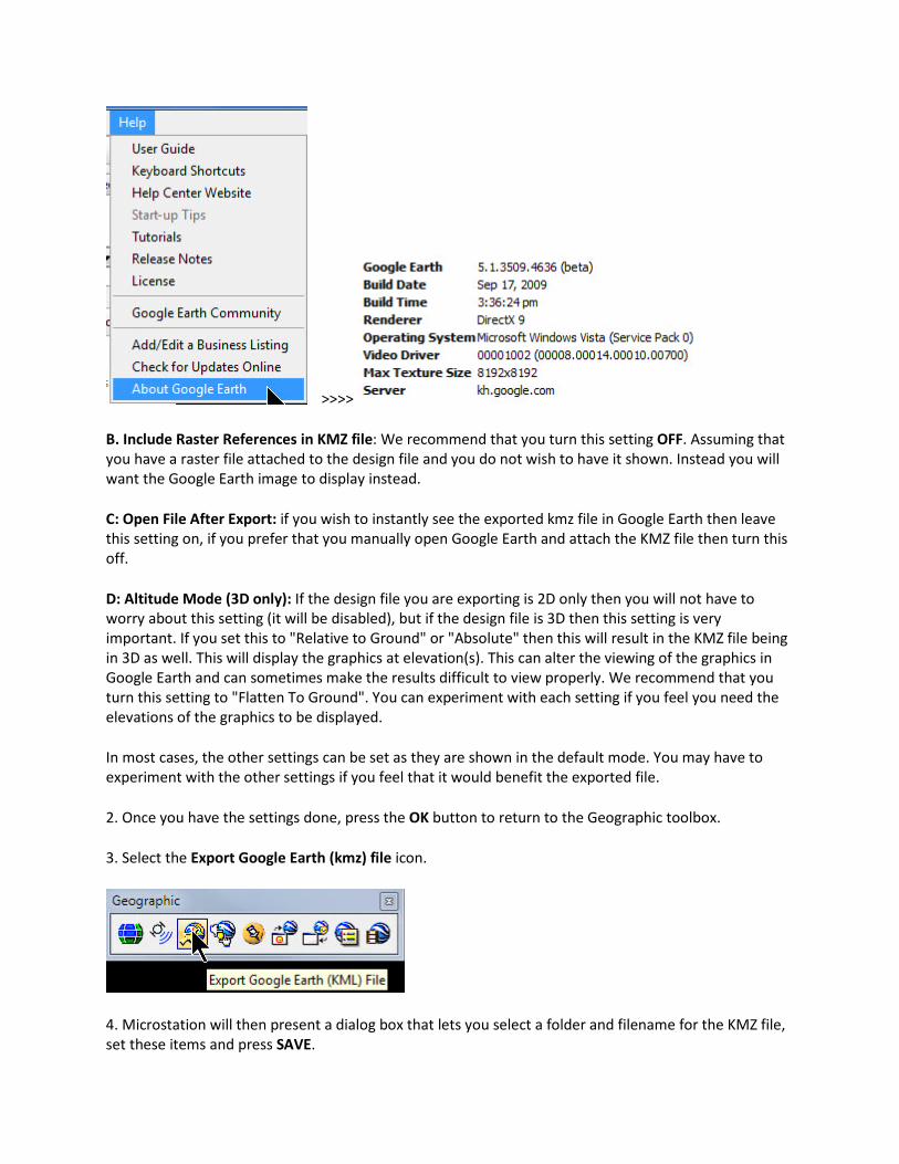
>>>>
B. Include Raster References in KMZ file: We recommend that you turn this setting OFF. Assuming that you have a raster file attached to the design file and you do not wish to have it shown. Instead you will want the Google Earth image to display instead.
C: Open File After Export: if you wish to instantly see the exported kmz file in Google Earth then leave this setting on, if you prefer that you manually open Google Earth and attach the KMZ file then turn this off.
D: Altitude Mode (3D only): If the design file you are exporting is 2D only then you will not have to worry about this setting (it will be disabled), but if the design file is 3D then this setting is very important. If you set this to "Relative to Ground" or "Absolute" then this will result in the KMZ file being in 3D as well. This will display the graphics at elevation(s). This can alter the viewing of the graphics in Google Earth and can sometimes make the results difficult to view properly. We recommend that you turn this setting to "Flatten To Ground". You can experiment with each setting if you feel you need the elevations of the graphics to be displayed.
In most cases, the other settings can be set as they are shown in the default mode. You may have to experiment with the other settings if you feel that it would benefit the exported file.
2. Once you have the settings done, press the OK button to return to the Geographic toolbox.
3. Select the Export Google Earth (kmz) file icon.
4. Microstation will then present a dialog box that lets you select a folder and filename for the KMZ file, set these items and press SAVE.

If you had selected the "Open File After Export" option, Google earth will automatically open with the graphic you exported displayed in the view. If not open Google Earth and select FILE > OPEN. Locate the kmz file you created and it will load and display.
Saving the KMZ file for later viewing
This location is placed in Google Earth's "Temporary Places" section of the interface. If you close Google Earth and you do not save this place then it will not be loaded the next time you start it.
1. To save the "Temporary Place" inside Google Earth, select FILE > SAVE option and either save to "My Places" or use the Save As option to create a new place to save it. Doing this will allow you to display this kmz file later without to reload the kmz file. Be aware that this only applies to your personal computer only. To show the kmz file at another computer you must transfer the kmz file to that computer and load it into Google Earth.