Embed Size (px)
Citation preview
INSTRUCTIONS
NMM-800RF∕ TRF
SYSTEM METALLURGICAL
MICROSCOPE
TIM5 User Guide
Material Inspection Microscope
1
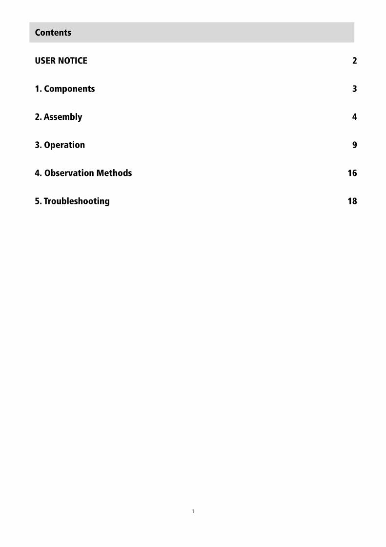
Contents
USER NOTICE 2
1. Components 3
2. Assembly 4
3. Operation 9
4. Observation Methods 16
5. Troubleshooting 18
2
User Notices
I. Safety note
i. When unpacking, please take care not to drop fragile items, such as lenses.
ii. Keep the instrument out of direct sunlight; avoid high temperatures or humidity, dusty environments. Make sure the work
surface is stable and away from sources of vibration.
iii. Take care when moving the instrument, using two hands to grip with the sides of the microscope body.
iv. Caution! The lamp house and nearby parts will be very hot during operation. Ensure sufficient space to allow cooling.
v. Before replacing the halogen lamp, or fuse, make sure the main switch is in the “O” (off) position, and turn off the mains
power. Allow the lamp bulb and lamp house completely cool before removal.
vi. Use the factory supplied power cord.
II. Maintenance
i. Do not disassemble any parts of the microscope, as it will affect function, or reduce the performance.
ii. Keep the instrument clean and cover with a dust cover when not in use. Remove dust with a lint-free cloth. Take care to
avoid contaminating the optical elements.
iii. Marks on the prism, such as finger marks or oil should be removed by gently wiped with a piece of lint-free cloth immersed
in pure alcohol or xylene (NOTE: alcohol and xylene are highly flammable. Keep away from heat sources and use them in a
well-ventilated room).
iv. Do not use organic solvent to wipe the non-optical elements.
v. Place the instrument in a cool, dry environment. After using the microscope, cover with a dust cover.
Wait for the lamp house to cool completely before covering.
3
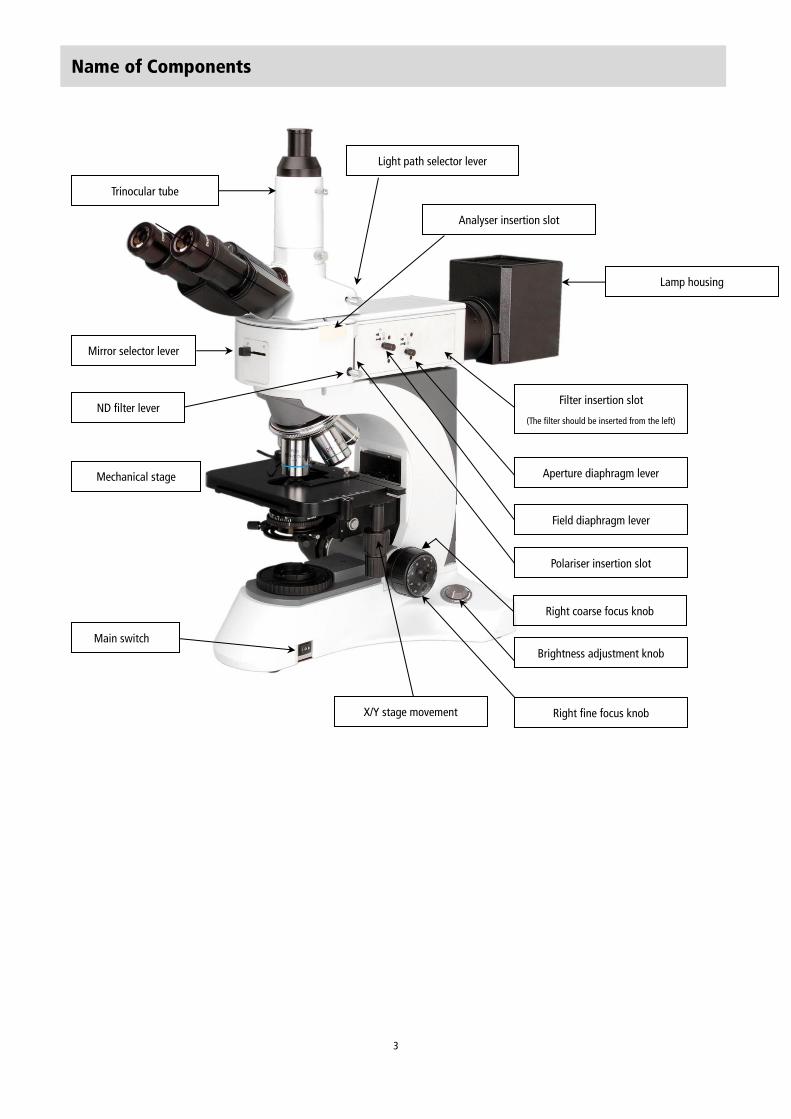
Name of Components
Light path selector lever
Analyser insertion slot
ND filter lever
Polariser insertion slot
Aperture diaphragm lever
Field diaphragm lever
拉杆
Main switch
Brightness adjustment knob
Right fine focus knob
Mechanical stage
X/Y stage movement
Lamp housing
Trinocular tube
Filter insertion slot
(The filter should be inserted from the left)
Right coarse focus knob
Mirror selector lever
4
2.Installation
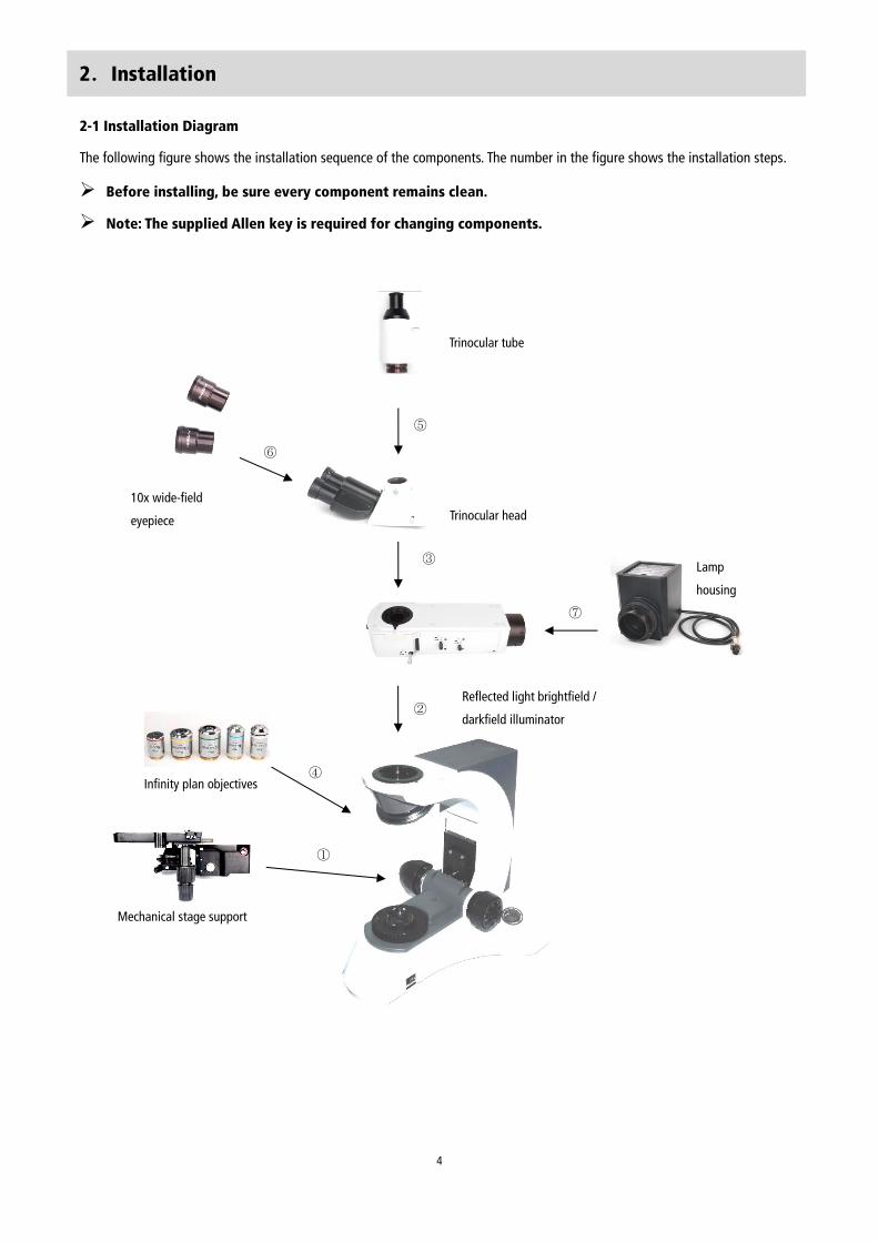
2-1 Installation Diagram
The following figure shows the installation sequence of the components. The number in the figure shows the installation steps.
Before installing, be sure every component remains clean.
Note: The supplied Allen key is required for changing components.
Trinocular tube
Trinocular head
10x wide-field
eyepiece
Lamp
housing
Reflected light brightfield /
darkfield illuminator
Infinity plan objectives
Infinite Plan Objective
Infinite Plan Objective
Mechanical stage support
①
⑤
⑥
③
⑦
④
②
5
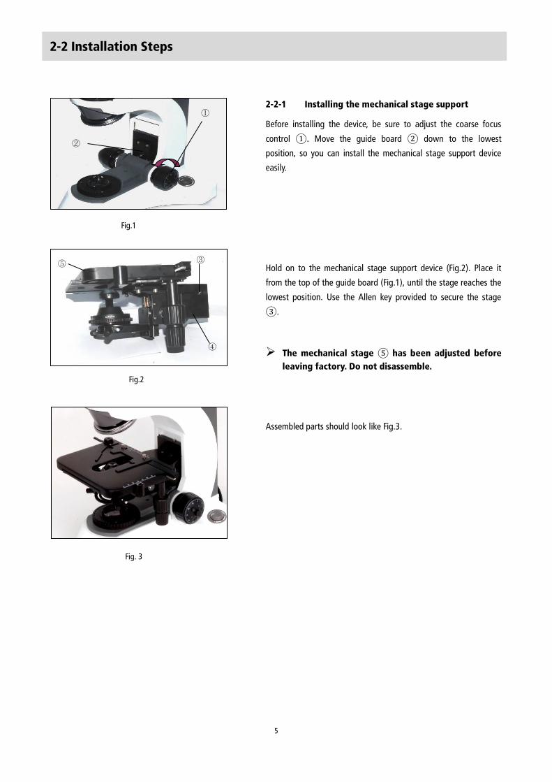
2-2 Installation Steps
2-2-1 Installing the mechanical stage support
Before installing the device, be sure to adjust the coarse focus
control ①. Move the guide board ② down to the lowest
position, so you can install the mechanical stage support device
easily.
Hold on to the mechanical stage support device (Fig.2). Place it
from the top of the guide board (Fig.1), until the stage reaches the
lowest position. Use the Allen key provided to secure the stage
③.
The mechanical stage ⑤ has been adjusted before
leaving factory. Do not disassemble.
Assembled parts should look like Fig.3.
Fig.2
⑤ ③
④
Fig. 3
Fig.1
②
①
6
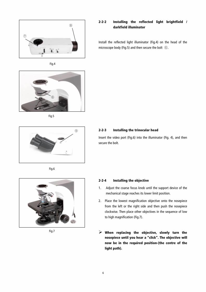
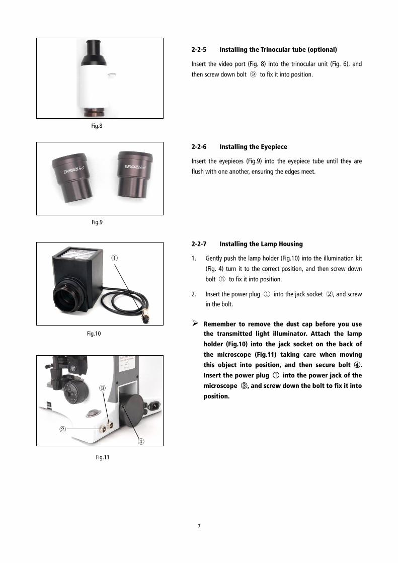
2-2-2 Installing the reflected light brightfield /
darkfield illuminator
Install the reflected light illuminator (Fig.4) on the head of the
microscope body (Fig.5) and then secure the bolt ⑥.
2-2-3 Installing the trinocular head
Insert the video port (Fig.6) into the illuminator (Fig. 4), and then
secure the bolt.
2-2-4 Installing the objective
1. Adjust the coarse focus knob until the support device of the
mechanical stage reaches its lower limit position.
2. Place the lowest magnification objective onto the nosepiece
from the left or the right side and then push the nosepiece
clockwise. Then place other objectives in the sequence of low
to high magnification (Fig.7).
When replacing the objective, slowly turn the
nosepiece until you hear a “click”. The objective will
now be in the required position-(the centre of the
light path).
Fig.5
⑥
Fig.6
⑨
Fig.7
⑦
⑧
Fig.4
7
2-2-5 Installing the Trinocular tube (optional)
Insert the video port (Fig. 8) into the trinocular unit (Fig. 6), and
then screw down bolt ⑨ to fix it into position.
2-2-6 Installing the Eyepiece
Insert the eyepieces (Fig.9) into the eyepiece tube until they are
flush with one another, ensuring the edges meet.
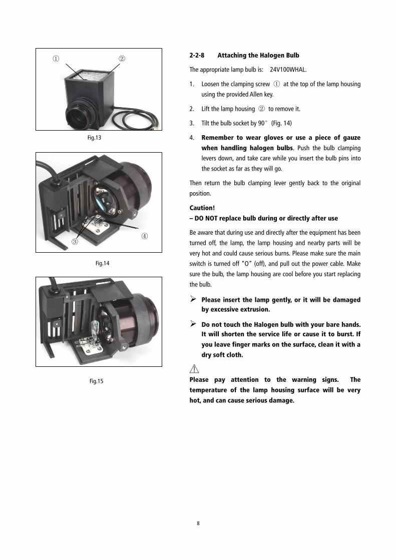
2-2-7 Installing the Lamp Housing
1. Gently push the lamp holder (Fig.10) into the illumination kit
(Fig. 4) turn it to the correct position, and then screw down
bolt ⑧ to fix it into position.
2. Insert the power plug ① into the jack socket ②, and screw
in the bolt.
Remember to remove the dust cap before you use
the transmitted light illuminator. Attach the lamp
holder (Fig.10) into the jack socket on the back of
the microscope (Fig.11) taking care when moving
this object into position, and then secure bolt ④.
Insert the power plug ① into the power jack of the
microscope ③, and screw down the bolt to fix it into
position.
Fig.8
Fig.9
Fig.10
①
Fig.11
②
③
④
8
Fig.13
① ②
Fig.14
③ ④
Fig.15
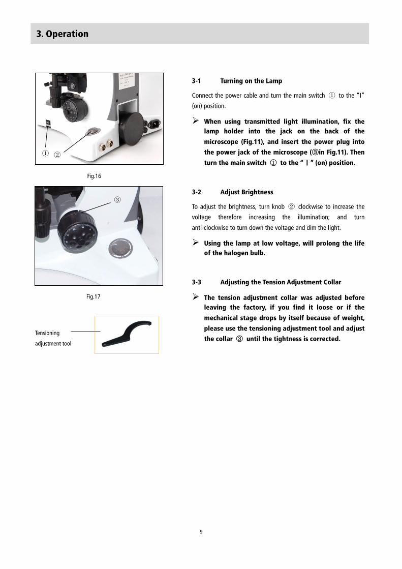
2-2-8 Attaching the Halogen Bulb
The appropriate lamp bulb is: 24V100WHAL.
1. Loosen the clamping screw ① at the top of the lamp housing
using the provided Allen key.
2. Lift the lamp housing ② to remove it.
3. Tilt the bulb socket by 90°(Fig. 14)
4. Remember to wear gloves or use a piece of gauze
when handling halogen bulbs. Push the bulb clamping
levers down, and take care while you insert the bulb pins into
the socket as far as they will go.
Then return the bulb clamping lever gently back to the original
position.
Caution!
– DO NOT replace bulb during or directly after use
Be aware that during use and directly after the equipment has been
turned off, the lamp, the lamp housing and nearby parts will be
very hot and could cause serious burns. Please make sure the main
switch is turned off “O” (off), and pull out the power cable. Make
sure the bulb, the lamp housing are cool before you start replacing
the bulb.
Please insert the lamp gently, or it will be damaged
by excessive extrusion.
Do not touch the Halogen bulb with your bare hands.
It will shorten the service life or cause it to burst. If
you leave finger marks on the surface, clean it with a
dry soft cloth.
Please pay attention to the warning signs. The
temperature of the lamp housing surface will be very
hot, and can cause serious damage.
9
3. Operation
3-1 Turning on the Lamp
Connect the power cable and turn the main switch ① to the “I”
(on) position.
When using transmitted light illumination, fix the
lamp holder into the jack on the back of the
microscope (Fig.11), and insert the power plug into
the power jack of the microscope (③in Fig.11). Then
turn the main switch ① to the “‖” (on) position.
3-2 Adjust Brightness
To adjust the brightness, turn knob ② clockwise to increase the
voltage therefore increasing the illumination; and turn
anti-clockwise to turn down the voltage and dim the light.
Using the lamp at low voltage, will prolong the life
of the halogen bulb.
3-3 Adjusting the Tension Adjustment Collar
The tension adjustment collar was adjusted before
leaving the factory, if you find it loose or if the
mechanical stage drops by itself because of weight,
please use the tensioning adjustment tool and adjust
the collar ③ until the tightness is corrected.
Fig.16
① ②
Tensioning
adjustment tool
③
Fig.17
10
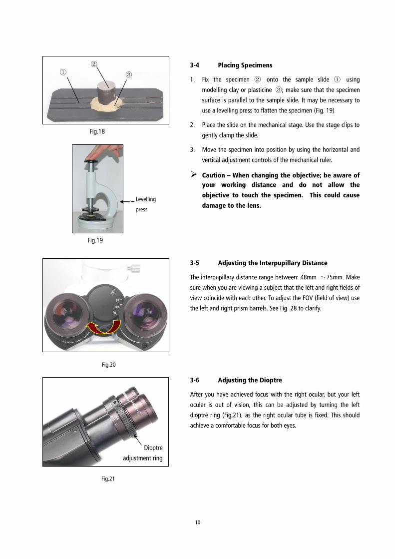
3-4 Placing Specimens
1. Fix the specimen ② onto the sample slide ① using
modelling clay or plasticine ③; make sure that the specimen
surface is parallel to the sample slide. It may be necessary to
use a levelling press to flatten the specimen (Fig. 19)
2. Place the slide on the mechanical stage. Use the stage clips to
gently clamp the slide.
3. Move the specimen into position by using the horizontal and
vertical adjustment controls of the mechanical ruler.
Caution – When changing the objective; be aware of
your working distance and do not allow the
objective to touch the specimen. This could cause
damage to the lens.
3-5 Adjusting the Interpupillary Distance
The interpupillary distance range between: 48mm ~75mm. Make
sure when you are viewing a subject that the left and right fields of
view coincide with each other. To adjust the FOV (field of view) use
the left and right prism barrels. See Fig. 28 to clarify.
3-6 Adjusting the Dioptre
After you have achieved focus with the right ocular, but your left
ocular is out of vision, this can be adjusted by turning the left
dioptre ring (Fig.21), as the right ocular tube is fixed. This should
achieve a comfortable focus for both eyes.
Fig.20
图 18
Fig.18
①
②
③
Fig.19
Levelling
press
Fig.21
Dioptre
adjustment ring
11
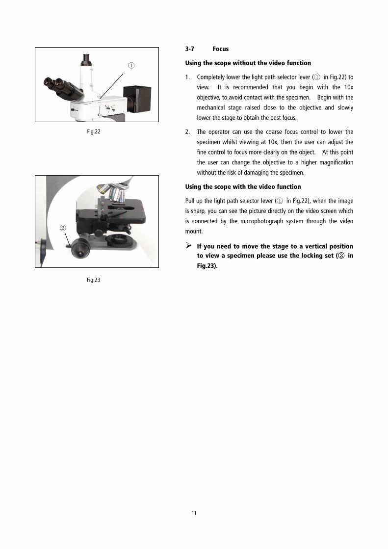
3-7 Focus
Using the scope without the video function
1. Completely lower the light path selector lever (① in Fig.22) to
view. It is recommended that you begin with the 10x
objective, to avoid contact with the specimen. Begin with the
mechanical stage raised close to the objective and slowly
lower the stage to obtain the best focus.
2. The operator can use the coarse focus control to lower the
specimen whilst viewing at 10x, then the user can adjust the
fine control to focus more clearly on the object. At this point
the user can change the objective to a higher magnification
without the risk of damaging the specimen.
Using the scope with the video function
Pull up the light path selector lever (① in Fig.22), when the image
is sharp, you can see the picture directly on the video screen which
is connected by the microphotograph system through the video
mount.
If you need to move the stage to a vertical position
to view a specimen please use the locking set (② in
Fig.23).
①
Fig.22
Fig.23
②
12
Fig.24
Fig.26
② ④
Usable Filters Applications
Colour temperature
conversion filter
Turns the illumination light into daylight. Used in general
observations and colour photography.
Green filter Enhanced contrast in monochrome observation. Used in
monochrome photography
Yellow filter Contrast filter for observation of semiconductor wafers
Frost filter Reduces irregularity in the illumination field, but also
reduces the brightness
ND25 Adjusts the brightness of the light source.
(Transmittance: 25%)
ND6 Adjusts the brightness of the light source.
(Transmittance: 6%)
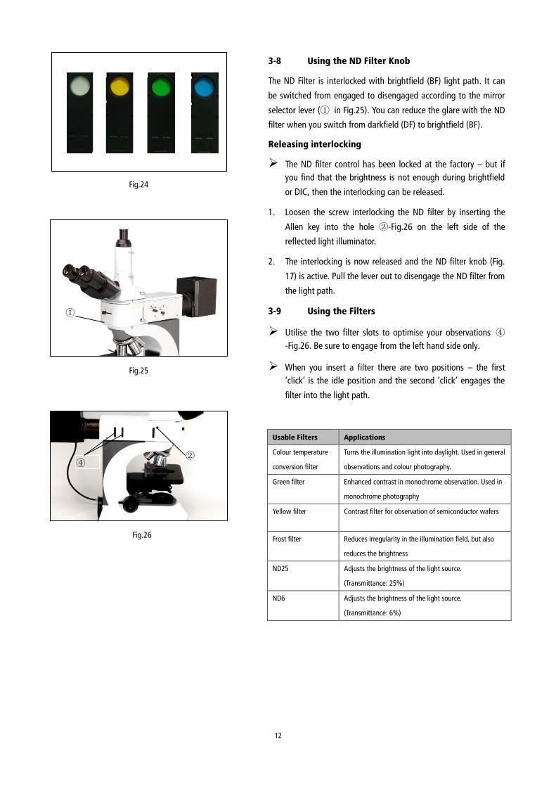
3-8 Using the ND Filter Knob
The ND Filter is interlocked with brightfield (BF) light path. It can
be switched from engaged to disengaged according to the mirror
selector lever (① in Fig.25). You can reduce the glare with the ND
filter when you switch from darkfield (DF) to brightfield (BF).
Releasing interlocking
The ND filter control has been locked at the factory – but if
you find that the brightness is not enough during brightfield
or DIC, then the interlocking can be released.
1. Loosen the screw interlocking the ND filter by inserting the
Allen key into the hole ②-Fig.26 on the left side of the
reflected light illuminator.
2. The interlocking is now released and the ND filter knob (Fig.
17) is active. Pull the lever out to disengage the ND filter from
the light path.
3-9 Using the Filters
Utilise the two filter slots to optimise your observations ④
-Fig.26. Be sure to engage from the left hand side only.
When you insert a filter there are two positions – the first
‘click’ is the idle position and the second ‘click’ engages the
filter into the light path.
③
①
Fig.25
13
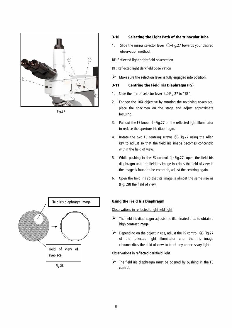
3-10 Selecting the Light Path of the trinocular Tube
1. Slide the mirror selector lever ①–Fig.27 towards your desired
observation method.
BF: Reflected light brightfield observation
DF: Reflected light darkfield observation
Make sure the selection lever is fully engaged into position.
3-11 Centring the Field Iris Diaphragm (FS)
1. Slide the mirror selector lever ①-Fig.27 to “BF”.
2. Engage the 10X objective by rotating the revolving nosepiece,
place the specimen on the stage and adjust approximate
focusing.
3. Pull out the FS knob ④-Fig.27 on the reflected light illuminator
to reduce the aperture iris diaphragm.
4. Rotate the two FS centring screws ②-Fig.27 using the Allen
key to adjust so that the field iris image becomes concentric
within the field of view.
5. While pushing in the FS control ④-Fig.27, open the field iris
diaphragm until the field iris image inscribes the field of view. If
the image is found to be eccentric, adjust the centring again.
6. Open the field iris so that its image is almost the same size as
(Fig. 28) the field of view.
Using the Field Iris Diaphragm
Observations in reflected brightfield light
The field iris diaphragm adjusts the illuminated area to obtain a
high contrast image.
Depending on the object in use, adjust the FS control ④-Fig.27
of the reflected light illuminator until the iris image
circumscribes the field of view to block any unnecessary light.
Observations in reflected darkfield light
The field iris diaphragm must be opened by pushing in the FS
control.
①
② ③
④ ⑤
Fig.27
Fig.28
Field iris diaphragm image
阑图象
Field of view of
eyepiece
14
3-12 Centring the Aperture Iris Diaphragm (AS)
1. Slide the mirror selector lever to “BF”.
2. Engage the 10X objective by rotating the revolving nosepiece,
place the specimen on the stage and adjust approximate focusing.
3. Remove the eyepiece, look into the eyepiece sleeve and pull the AS
knob (⑤ in Fig.27), so that the aperture is about 70% open.
4. If the centre of the iris diaphragm is deviated, centre it by rotating
the two AS centring screws (③ in Fig. 27) using the Allen key.
Using the Aperture Iris Diaphragm
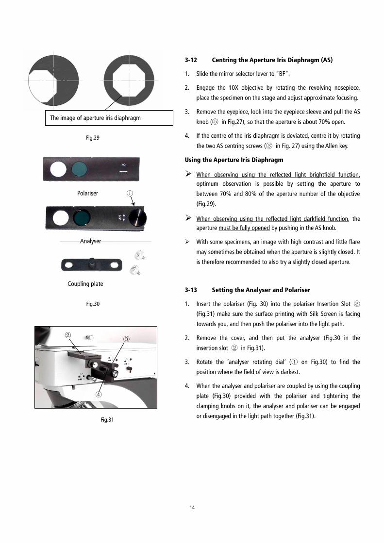
When observing using the reflected light brightfield function,
optimum observation is possible by setting the aperture to
between 70% and 80% of the aperture number of the objective
(Fig.29).
When observing using the reflected light darkfield function, the
aperture must be fully opened by pushing in the AS knob.
With some specimens, an image with high contrast and little flare
may sometimes be obtained when the aperture is slightly closed. It
is therefore recommended to also try a slightly closed aperture.
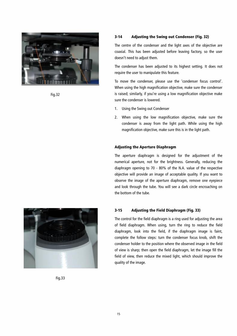
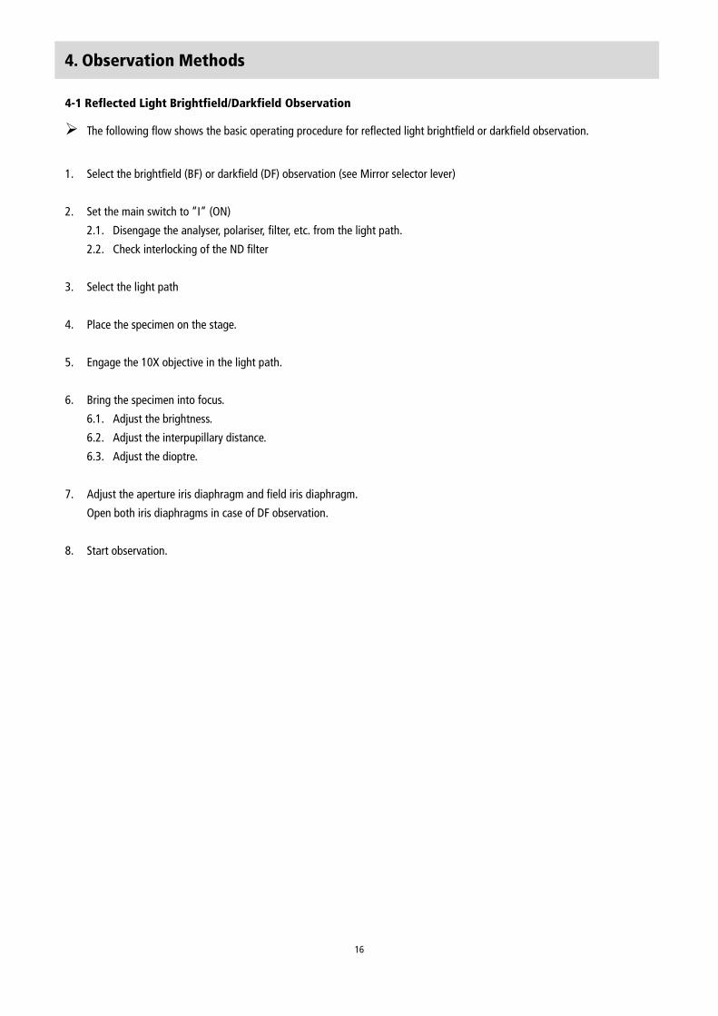
3-13 Setting the Analyser and Polariser
1. Insert the polariser (Fig. 30) into the polariser Insertion Slot ③
(Fig.31) make sure the surface printing with Silk Screen is facing
towards you, and then push the polariser into the light path.
2. Remove the cover, and then put the analyser (Fig.30 in the
insertion slot ② in Fig.31).
3. Rotate the ‘analyser rotating dial’ (① on Fig.30) to find the
position where the field of view is darkest.
4. When the analyser and polariser are coupled by using the coupling
plate (Fig.30) provided with the polariser and tightening the
clamping knobs on it, the analyser and polariser can be engaged
or disengaged in the light path together (Fig.31).
Fig.29
The image of aperture iris diaphragm
①
Fig.30
Polariser
Coupling plate
Analyser
Fig.31
②
④
③
15
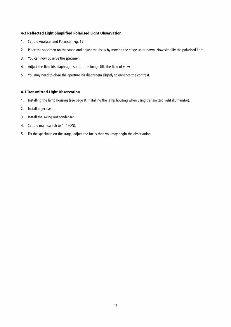
3-14 Adjusting the Swing out Condenser (Fig. 32)
The centre of the condenser and the light axes of the objective are
coaxial. This has been adjusted before leaving factory, so the user
doesn’t need to adjust them.
The condenser has been adjusted to its highest setting. It does not
require the user to manipulate this feature.
To move the condenser, please use the ‘condenser focus control’.
When using the high magnification objective, make sure the condenser
is raised; similarly, if you’re using a low magnification objective make
sure the condenser is lowered.
1. Using the Swing out Condenser
2. When using the low magnification objective, make sure the
condenser is away from the light path. While using the high
magnification objective, make sure this is in the light path.
Adjusting the Aperture Diaphragm
The aperture diaphragm is designed for the adjustment of the
numerical aperture, not for the brightness. Generally, reducing the
diaphragm opening to 70 - 80% of the N.A. value of the respective
objective will provide an image of acceptable quality. If you want to
observe the image of the aperture diaphragm, remove one eyepiece
and look through the tube. You will see a dark circle encroaching on
the bottom of the tube.
3-15 Adjusting the Field Diaphragm (Fig. 33)
The control for the field diaphragm is a ring used for adjusting the area
of field diaphragm. When using, turn the ring to reduce the field
diaphragm, look into the field, if the diaphragm image is faint,
complete the follow steps: turn the condenser focus knob, shift the
condenser holder to the position where the observed image in the field
of view is sharp; then open the field diaphragm, let the image fill the
field of view, then reduce the mixed light, which should improve the
quality of the image.
Fig.32
Fig.33
16
4. Observation Methods
4-1 Reflected Light Brightfield/Darkfield Observation
The following flow shows the basic operating procedure for reflected light brightfield or darkfield observation.
1. Select the brightfield (BF) or darkfield (DF) observation (see Mirror selector lever)
2. Set the main switch to “I” (ON)
2.1. Disengage the analyser, polariser, filter, etc. from the light path.
2.2. Check interlocking of the ND filter
3. Select the light path
4. Place the specimen on the stage.
5. Engage the 10X objective in the light path.
6. Bring the specimen into focus.
6.1. Adjust the brightness.
6.2. Adjust the interpupillary distance.
6.3. Adjust the dioptre.
7. Adjust the aperture iris diaphragm and field iris diaphragm.
Open both iris diaphragms in case of DF observation.
8. Start observation.
17
4-2 Reflected Light Simplified Polarised Light Observation
1. Set the Analyser and Polariser (Fig. 15).
2. Place the specimen on the stage and adjust the focus by moving the stage up or down. Now simplify the polarised light
3. You can now observe the specimen.
4. Adjust the field iris diaphragm so that the image fills the field of view.
5. You may need to close the aperture iris diaphragm slightly to enhance the contrast.
4-3 Transmitted Light Observation
1. Installing the lamp housing (see page 8: Installing the lamp housing when using transmitted light illuminator).
2. Install objective.
3. Install the swing out condenser.
4. Set the main switch to “II” (ON).
5. Fix the specimen on the stage; adjust the focus then you may begin the observation.
18
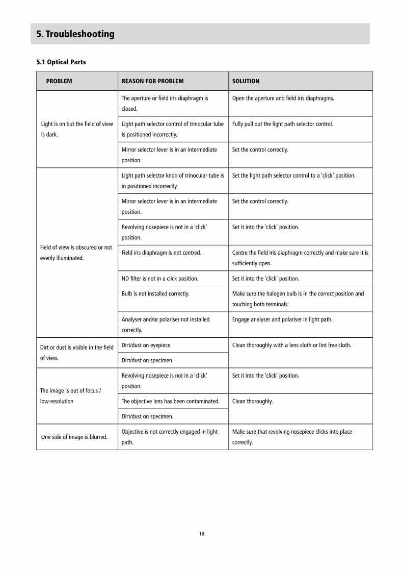
5. Troubleshooting
5.1 Optical Parts
PROBLEM REASON FOR PROBLEM SOLUTION
Light is on but the field of view
is dark.
The aperture or field iris diaphragm is
closed.
Open the aperture and field iris diaphragms.
Light path selector control of trinocular tube
is positioned incorrectly.
Fully pull out the light path selector control.
Mirror selector lever is in an intermediate
position.
Set the control correctly.
Field of view is obscured or not
evenly illuminated.
Light path selector knob of trinocular tube is
in positioned incorrectly.
Set the light path selector control to a ‘click’ position.
Mirror selector lever is in an intermediate
position.
Set the control correctly.
Revolving nosepiece is not in a ‘click’
position.
Set it into the ‘click’ position.
Field iris diaphragm is not centred. Centre the field iris diaphragm correctly and make sure it is
sufficiently open.
ND filter is not in a click position. Set it into the ‘click’ position.
Bulb is not installed correctly. Make sure the halogen bulb is in the correct position and
touching both terminals.
Analyser and/or polariser not installed
correctly.
Engage analyser and polariser in light path.
Dirt or dust is visible in the field
of view.
Dirt/dust on eyepiece. Clean thoroughly with a lens cloth or lint free cloth.
Dirt/dust on specimen.
The image is out of focus /
low-resolution
Revolving nosepiece is not in a ‘click’
position.
Set it into the ‘click’ position.
The objective lens has been contaminated. Clean thoroughly.
Dirt/dust on specimen.
One side of image is blurred. Objective is not correctly engaged in light
path.
Make sure that revolving nosepiece clicks into place
correctly.
19
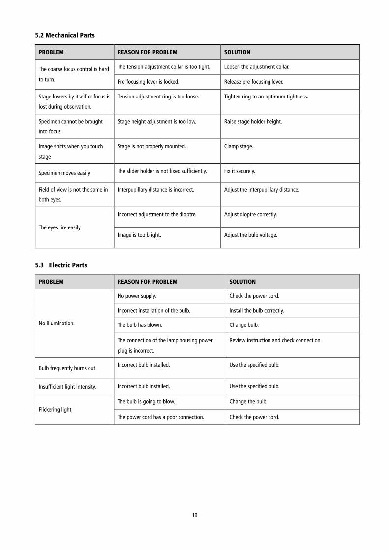
5.2 Mechanical Parts
PROBLEM REASON FOR PROBLEM SOLUTION
The coarse focus control is hard
to turn.
The tension adjustment collar is too tight. Loosen the adjustment collar.
Pre-focusing lever is locked. Release pre-focusing lever.
Stage lowers by itself or focus is
lost during observation.
Tension adjustment ring is too loose. Tighten ring to an optimum tightness.
Specimen cannot be brought
into focus.
Stage height adjustment is too low. Raise stage holder height.
Image shifts when you touch
stage
Stage is not properly mounted. Clamp stage.
Specimen moves easily. The slider holder is not fixed sufficiently. Fix it securely.
Field of view is not the same in
both eyes.
Interpupillary distance is incorrect. Adjust the interpupillary distance.
The eyes tire easily.
Incorrect adjustment to the dioptre. Adjust dioptre correctly.
Image is too bright. Adjust the bulb voltage.
5.3 Electric Parts
PROBLEM REASON FOR PROBLEM SOLUTION
No illumination.
No power supply. Check the power cord.
Incorrect installation of the bulb. Install the bulb correctly.
The bulb has blown. Change bulb.
The connection of the lamp housing power
plug is incorrect.
Review instruction and check connection.
Bulb frequently burns out. Incorrect bulb installed. Use the specified bulb.
Insufficient light intensity. Incorrect bulb installed. Use the specified bulb.
Flickering light.
The bulb is going to blow. Change the bulb.
The power cord has a poor connection. Check the power cord.

20
LIT5
07
2 R
1.0
/08
14