Embed Size (px)
Citation preview

P1: VENDOR
Journal of Science Education and Technology PP026-290012 December 26, 2000 12:30 Style file version Oct. 23, 2000
Journal of Science Education and Technology, Vol. 10, No. 1, 2001
MicroObservatory Net: A Network of Automated RemoteTelescopes Dedicated to Educational Use
Philip M. Sadler,1,2 Roy R. Gould,1 P. Steven Leiker,1 Paul R. A. Antonucci,1
Robert Kimberk,1 Freeman S. Deutsch,1 Beth Hoffman,3 Mary Dussault,1
Adam Contos,1 Kenneth Brecher,4 and Linda French5
Many students have a deep interest in astronomy, but a limited opportunity to use telescopesto explore the heavens. The MicroObservatory Network of automated telescopes is designedto provide access to classroom teachers who wish their students to conduct projects over theWorld Wide Web. The intuitive interface makes it easy for even 10-year-olds to take pic-tures. Telescopes can be remotely pointed and focused; filters, field of view, and exposuretimes can be changed easily. Images are archived at the website, along with sample challengesand a user bulletin board, all of which encourage collaboration among schools. Wide geo-graphic separation of instruments provides access to distant night skies during local daytime.Since “first light” in 1995, we have learned much about remote troubleshooting, designingfor unattended use, and for acquiring the kinds of images that students desire. This networkcan be scaled up from its present capability of 240,000 images each year to provide telescopeaccess for all US students with an interest in astronomy. Our WWW address is http://mo-www.harvard.edu/MicroObservatory/
KEY WORDS: Astronomy; science education; telescope; computer control; remote experiment; WorldWide Web.
INTRODUCTION
Five MicroObservatories make up an experimen-tal network of computer-driven, automated imagingtelescopes designed to allow students unprecedentedaccess to the night sky. With a limited opportunity forstudents in most schools to make astronomical obser-vations, this system utilizes the World Wide Web toopen the heavens up for study. Our telescope networkwas awarded the 1998 Computers in Physics Prize by
1Harvard-Smithsonian Center for Astrophysics, 60 Garden StreetMS-71, Cambridge, Massachusetts 02138.
2Harvard University Graduate School of Education, LongfellowHall 312, Appian Way, Cambridge, Massachusetts.
3Education Development Center, 55 Chapel Street, Newton, Mas-sachusetts 02458.
4Boston University, Department of Astronomy, 725 Common-wealth Ave., Boston, Massachusetts 02215.
5Wheelock College, 200 The Riverway, Boston, Massachusetts02215.
the American Institute of Physics. This paper followsthe evolution of the network from initial prototypes,documenting the technical hurdles that had to be sur-mounted to build an efficient and robust system. Itdescribes the uses to which students have put the sys-tem and our plans for future development.
Three Innovations
Over the last decade, four new developmentshave “fast-forwarded” astronomical observationtechniques, moving it from a labor-intensive indus-try to one making the most of electronic innovation:detectors, robotic control, the Internet, and digital im-age processing.
Electronic imaging detectors, typically charge-coupled devices (CCDs) have supplanted the older,chemical technology of photography. Nowhere isthis more apparent than in orbiting satellites andfly-by probes that digitize their images and transmit
39
1059-0145/01/0300-0039$19.50/0 C© 2001 Plenum Publishing Corporation

P1: VENDOR
Journal of Science Education and Technology PP026-290012 December 26, 2000 12:30 Style file version Oct. 23, 2000
40 Sadler et al.
them back to earth. CCDs have worked their wayinto consumer products as well; hand-held videocamcorders and still cameras are the most visibleexamples. Now, even film-producing giants such asKodak have committed to producing high-densityimagers and marketing fully electronic still cameras(Harris, 1986; Huchra, 1988).
A less conspicuous, but equally impressivechange, has been robotic automation. Many tele-scopes are now controlled completely off site(Baliunas et al., 1987). Observers can change instru-ments, point, and control a large number of fea-tures without ever traveling to the site (Philip andHayes, 1992). Louis Boyd’s “Phoenix-10” is generallyrecognized to be the first fully automated telescope(Boyd, 1985) although proposals for full automationare found in earlier literature (McCord, Snellen, andPaavola, 1972).
The Internet has made two-way communicationof data simple. Today, 90% of the W.M. Keck Observa-tory’s observations are conducted remotely (Kilbricket al., 1998). Scientists have made available dial-incontrol for educational use of former research remotetelescopes (Clark and Jashow, 1994; Pennypacker,1997; Ratcliffe, 1994) and custom constructed indi-vidual instruments (McCullough and Thakkar, 1997;O’Connor, 1994). The control of world-wide dedi-cated networks of telescopes has been assumed to bea natural progression in the utilization of remote tele-scopes (Genet, 1992).
The fourth major change in observational tech-nology was made possible by the increasing power ofmicrocomputers to perform digital image processing.Electronically acquired images are custom-made forcomputer manipulation so as to reduce noise and de-fects. Image processing increases the match betweenlinear detectors and the intrinsically logarithmic hu-man eye, and makes measurement easy. Originallycreated for scientific and medical purposes, imageprocessing is now commonly used for the manipula-tion of photographic images by professional and ama-teur photographers through widely available softwareprograms.6
These four innovations have increasingly beenincorporated into professional research instrumentsand are available individually for higher-end ama-teur telescopes (Mallama, 1996).7 However, techni-cal skill and astronomical knowledge of the sky are
6Such as Photoshop, by Adobe Systems and National Institutes ofHealth’s Image.
7For example, in Meade’s LX50 and Celestron’s Celestar.
still essential for coaxing images from such instru-ments. One can think of them as providing better andmore accurate images for researchers and amateurs,but they have done little to make such experiencesavailable to schoolchildren.
The Ideal “Starter” Telescope
The intention of the MicroObservatory projectis to use advances in telescope design and image pro-cessing to allow students of all ages to take pictures ofobjects in the sky. Before this could happen, severalproblems had to be solved, problems that are quite dif-ferent from those encountered for use by more tech-nically sophisticated users.
Telescopes are designed to see the sky at night;there is not much to look at during the day, but moststudents find it difficult to return to school at night.This dilemma can be resolved either by use of a de-layed mode, in which students request images thatcan be taken while they are asleep, or by using ge-ographic displacement in longitude to take “live”images with a telescope many time zones away. Inreal-time, while students are in school and it is day-light, it is nighttime somewhere else in the world. Us-ing remote communication, they can observe fromthat far-away place. Both techniques, time-delay ortime-shift, present special problems for unattendedoperations. The cost of maintaining observatories,which are often unique collections of equipment andbuildings, is high. MicroObservatory telescopes areself-contained, rugged, and weatherproof, as well asportable. This design has several advantages for re-mote operation.
If a telescope can sit outside in all weatherconditions, an expensive enclosure is not needed.Moreover, research telescopes are usually mountedon permanent piers set in concrete requiring aninvestment in money and space. A telescope thatcan be easily moved and stand alone has a lowerinstallation cost. Virtually all amateur telescopessit on unstable tripods to hold them at eye level;they do not require a pier. These telescopes are notenvironmentally contained and must be dismantledbetween observing sessions. Yet not all componentsof a remote telescopes must be outdoors. The powersupply and controlling computer can remain indoorsas long as there is a cable connection between the“brain” and its outdoor “eyes.” The portability ofthe telescope also solves an enormous problem withmaintenance. If telescopes can be made portable

P1: VENDOR
Journal of Science Education and Technology PP026-290012 December 26, 2000 12:30 Style file version Oct. 23, 2000
MicroObservatory Net 41
enough, they can be packed up and shipped back toa maintenance facility where problems can be dealtwith in the lab through “remote engineering” (Zulstraet al., 1997). Telescopes that are mass produced andvirtually identical can replace one another, so that atwin can be transported to a particular location, setup, plugged into the power supply and computer, andits ailing sibling shipped back to receive proper care.
Multiple Users
Another problem that novices encounter is thatthe view through a typical instrument is for one indi-vidual at a time. Many teachers complain of setting upa telescope to look at some faint object and having thestudents one by one peer into the eyepiece. It does nottake long before a little bump points the instrumenttoward the interstellar void. This issue of only one per-son at a time being able to see through the telescopecan be resolved with eyepieces that split the image, buta better solution is to record the image electronicallyusing a detector. Anyone who is interested can viewthe image on a computer monitor. The advent of theWorld Wide Web makes it possible to take such im-ages and instead of mailing them to the observer, havethem reside on the website. In this way, the observer—or anyone else with an interest in the image—canview it. Students can examine the image and copy itfor their personal use. Detector-equipped instrumentsare the equivalent of beam splitters with thousands ofeyepieces, where many users can observe the sameimage, each seeing an exact copy of the original.
Pointing at a specific celestial object can some-times be very difficult. Pointing often requires an ex-cellent knowledge of the sky; most objects that areworth imaging are not visible to the naked eye. Onemust use stars that are bright enough in the targetobject’s vicinity and finder scopes to narrow in on aparticular object. Research instruments and high-endamateur instruments have incorporated ways to pointaccurately at any portion of the sky by entering ce-lestial coordinates or even the names of the objects.But for students with very little knowledge of the sky,even more help is needed. Only half of the objectsin the heavens are visible at one time, the other halfare below the horizon; no novice can easily tell if thedesired object is above the horizon. Moreover, evenafter taking a picture, it is often difficult for novices toidentify whether one has actually captured the imageof the desired object. For this reason, it is often usefulto have a finder telescope to select the object fromamong its companions in the heavens.
Student questions are many and complex, and ex-perts need to help students see objects that are faintor to control the telescope in special ways. Such helpconsists of the tacit knowledge that experts bring toobservational astronomy. It is this unwritten, hard-to-describe knowledge that must be embedded inany type of computer system designed for use bynovices. Tacit knowledge can be incorporated explic-itly, through help functions in a website, or implicitly,through the design of the site’s user interface, whereuser questions and difficulties are addressed within aparticular screen. In this way, students can find helpimmediately without moving through complex menusor multiple screens. Such software must be tested tofind which are the most common questions and diffi-culties, and then features must be built in to obviatethe need for such help, or that make help easy to find.For example, a student who submits a MicroObser-vatory image request for an object below the horizonreceives an immediate error message giving the neg-ative altitude of the object. This information allowsthe student to successfully modify her request.
Setting up telescopes is often time consuming,even for an experienced user, whether it requiresalignment procedures or simply familiarizing one-self with the idiosyncrasies of a particular instrument.Portable telescopes need to be aligned; permanenttelescopes have piers and need alignment only once.Our desire is for all our remote instruments to oper-ate identically for all users through the same softwareinterface.
Light pollution sets a limit on what can be seenfrom urban sites (Fig. 1). In cities, the bright stars,the planets, and moon are often the only visible ob-jects in the night sky. The use of a remote networkallows telescopes to be placed in ideal locations: siteswhere the skies are clear and dark. Sky brightness canreduce the visibility of faint objects, especially onesthat students want to take pictures of (diffuse nebu-lae, galaxies, globular clusters) so the ability to placetelescopes in places with low levels of light pollution isa tremendous advantage of remote instrumentation.
Recording what you see has always been a sourceof pleasure and pride for amateur astronomers. Yeteven the best photographic film has never had a quan-tum efficiency greater than 5%.8 However, the quan-tum efficiency of film pales in comparison to those ofCCDs, which run from 40–80%. Astrophotography isnotoriously difficult and expensive, but with a CCD,one can take an image, store it as information, andship it thousands of miles in an instant. The ability to
8This is still far better than the human eys’s 1% quantum efficiency.

P1: VENDOR
Journal of Science Education and Technology PP026-290012 December 26, 2000 12:30 Style file version Oct. 23, 2000
42 Sadler et al.
Fig. 1. M-57, the Ring Nebula. Images taken in the city (left, 60-second exposure, Harvard College Observatory, Cambridge,MA) and country (right, 45-second exposure, Mt. Hopkins, AZ). CCD artifacts (hot pixels) have been removed. Note that skybrightness hides details in the city image; stars are more easily recognized against the background noise in the dark-sky picture.
examine others’ images permits students to collabo-rate with peers from across the country.
THE MICROOBSERVATORY NETWORK
Five MicroObservatories are at the heart of thenetwork. Each is a self-contained, integrated system,named after a famous astronomer: Annie (AnnieJump Cannon), Ben (Benjamin Banaeker), Cecilia(Cecilia Payne Gaposhkin), Don (Donald Menzel),and Ed (Edward Pickering). Our five instrumentscover a wide geography. Two are located at theSmithsonian Observatory Visitor’s Center at MountHopkins, Arizona. One is at the Harvard College Ob-servatory in Cambridge, Massachusetts, and anotheris at the Smithsonian’s Submillimeter Array site atMauna Kea, Hiwaii. The last has been installed at theMount Stromlo Observatory at Canberra, Australia.
Mechanical Systems
MicroObservatory is a relatively small (3.5 ft/1.0 m tall) and compact telescope (Fig. 2). It standsabout as tall as the average 4-year-old. Unlike the av-erage preschooler, it can be disassembled into twoparts by removing four screws, each weighing lessthan 70 pounds (32 kg). It does not require a pier.It sits on three feet fitted with leveling screws, for softor hard surfaces. The telescope is machined primar-ily from lightweight 6061-T6 aluminum. The internal
Fig. 2. Testing MicroObservatories prior to placement at remotelocations. The telescopes are run through a battery of tests at ourfacility before being shipped to new homes. Note the alt-az andRA-dec axis of each instrument. The finder and main telescopeapertures are clearly visible along with weatherproof connectorsand cables. Its low profile increases stability and reduces windload.

P1: VENDOR
Journal of Science Education and Technology PP026-290012 December 26, 2000 12:30 Style file version Oct. 23, 2000
MicroObservatory Net 43
surfaces of the tube are anodized black. The tele-scope is easy to carry in its unconnected condition. Itcan be transported by common carrier (e.g., FederalExpress) and shipped back to our location in Cam-bridge for maintenance. Telescope parts are fullyinterchangeable.
We chose to have the exterior of the telescope an-odized clear to keep it from corroding from the acidityof rain or a salt water environment. Teflon is used asthe major bearing material. Unlike bronze bushingsor ball bearings, Teflon has low friction and “stiction”properties so that it is much easier to move with smallmotors. It is also water repellent. One does not needhigh starting torque to move the telescope parts.
For motors, the telescope uses off-the-shelfstepper-motors coupled to worm or spur gears. Allfasteners are stainless steel and critical joints aresealed with a room-temperature vulcanizing (RTV)silicon rubber. Delrin is used for low-strength inter-nal parts. Lithium grease is used on all gear drives ex-tending the operating range down to−40◦F (−40◦C).The telescope is usable in both temperate and arcticconditions.
The telescope tube is environmentally, but nothermetically, sealed. Changes in barometric pressurewould make a hermetic seal undesirable. Our Teflonbearings provide an effective barrier to moisture.The optical tube is sealed well enough to be resistantto rain, snow, sleet, and ice. When the telescope is notin use, it points below the horizon to keep water fromcollecting on the corrector plate. Because the tele-scope is open to air pressure, water vapor can enterthe telescope and condense on the black radiatingsurfaces. For that reason, the telescope contains acharge of 200 g of silica gel desiccant. This gel lastsabout 2 years and can be recharged by heating inan oven.
Four-Axis System
The MicroObservatory telescope uses a four-axismount employing both polar and Alt-Az systems. TheAlt-Az axis is used only for remote polar alignment.This is accomplished initially by pointing at a refer-ence star. Errors in declination are detected by de-termining star drift in declination across the imagerwhen pointing at the eastern horizon. A nonsymmet-ric track of stars along the meridian indicates an er-ror in azimuth. The elevation and azimuth axis arethen adjusted and the star drift tests are repeated un-til alignment is satisfactory.
After alignment, the azimuth axis is locked downand the right ascension and declination polar drives
point and track the telescope. The right ascension axisuses a 360:1 worm-gear drive with a microsteppedmotor. Each turn of the worm produces a 1-degreechange in right ascension. The motor has 200 stepsper revolution with 32 microsteps per motor step.Each microstep is 1/6400 degrees, or approximately.56 arc-seconds. Successive microsteps are taken ap-proximately 37.4 milliseconds apart when tracking atthe sidereal rate. The declination axis uses a 100:1worm-gear drive with a half-stepped motor, with 400half-steps per revolution. This arrangement resultsin pointing resolution of .54 arc-minutes. Using step-per motors allows fine control of the position of theaxes.
Clutches on each axis make the instrument saferto be around while it is moving. The telescope simplystops moving when resistance is too great. This fea-ture also helps preserve the drivetrain if there is anyice obstructing telescope slewing or if the telescope ismanipulated manually.
Electronics
The electronics of the telescope are matched withits mechanical parts. The telescope contains a com-puter specially designed and built into the instrument.The control of all telescope functions is handled by anIntel 80C196KC microcontroller operating these pe-ripherals:
• Six motors: right ascension, declination, alti-tude, azimuth, a focus motor, and a filter wheelmotor.• Three solenoids: main camera shutter, finder
camera shutter, and finder neutral density filter(to permit the finder camera to be used duringthe daytime and to image the moon).• Two optical encoders: the right ascension axis
and the declination axis. Each breaks the cir-cle into 4096 positions per revolution (5.27 arc-minutes) from an origination position. Theworm of the right ascension drive also has anoptical break to detect the phase of the rightascension motor and to allow correction forphase error in the drive worm.• Four optical origination flags: six-position fil-
ter wheel, focus, and both altitude and azimuthaxes.• Four temperature sensors: main CCD, finder
CCD, main circuit board, and ambient tem-perature outside the telescope. These sensorsallow us to detect problems in cooling or over-heating of any of the parts.

P1: VENDOR
Journal of Science Education and Technology PP026-290012 December 26, 2000 12:30 Style file version Oct. 23, 2000
44 Sadler et al.
• Communications are handled by an AMD Eth-ernet controller, which can communicate withthe Macintosh computer by IEEE 802.3 proto-col, using a 10-Mbaud link.• Operation and communication with the main
and finder cameras.
Electronic components are accessible by removingthe top of the telescope tube (Fig. 3). All boards useremovable connectors and can be swapped easily dur-ing servicing.
There are two cameras in the telescope: a maincamera with a field of view of about 1 degree, anda finder camera with a field of view of about 10 de-grees. The cameras are controlled by a separate signalprocessing board interfaced to the 80C196KC micro-controller. The motors are handled by a separate mo-tor driver board, with the electronics to drive the
Fig. 3. Telescope electronics. The instrument uses an Intel80C196KC microcontroller to monitor encoders and other sensorsand to command the various motors and solenoids. Sensitive cam-era and communications circuits are isolated on separate circuitboards.
various motors and solenoids. These are large cur-rent devices and isolating them from the more sensi-tive computer and signal processing boards reducesnoise. Power is regulated at the board level to alsolimit noise. Most of the electronics are rated to−40◦F(−40◦C).
Electrical
The exterior power supply provides±24 V to thetelescope. The controlling computer communicatesfrom 80 ft (25 m) using twisted pair cable. Opticalfiber extends this to 2000 ft (600 m) and provides ad-ditional electrical isolation. Distance is not a problemas there is usually a building close enough to the tele-scope for both the power supply and the controllercomputer. All external cabling is weatherproof anduses commercial versions of military waterproof elec-trical connectors. The power supply averages 1.0 ampat 120 V AC.
Each of the cameras in the telescope—boththe main and finder cameras—contains a two-stagePeltier thermo-electric cooler that keeps the imagersat about 32◦F (0◦C). The computer circuit boards gen-erate enough heat to act as a “dew cap” for the tele-scope, keeping moisture from condensing on the radi-ating portions of the optical train. The main heatsinkhas exposed outboard fins, requiring no fans andhence no vibration from moving mechanical elementswhile the telescope is taking images.
Optical System
The main telescope utilizes a custom-designedand -built Maksutov optical design, with a focal lengthof 560 mm (Table I). The optical components ofthis design are a 6-inch spherical primary mirror, a5.25-inch corrector, a 1.875-inch diagonal mirror, fo-cusing lens, shutter, and a filter wheel. The filter wheelholds several photometric filters—B, V, R, and I—and one neutral density filter (ND 4) for taking pic-tures of the sun and moon. A clear optical flat ina sixth position preserves focus when a filter is notrequired. The Maksutov has good wide field charac-teristics with little aberration out to the edges of the1-degrees field of view and less sensitivity to collima-tion errors. We decided to use an integral correctorsystem instead of a Newtonian system because it hasa more distortion-free wide field of view. The findertelescope has a 28 mm f/2.8 camera lens,9 a shutter,
9Donated by Minolta USA.
P1: VENDOR
Journal of Science Education and Technology PP026-290012 December 26, 2000 12:30 Style file version Oct. 23, 2000
MicroObservatory Net 45
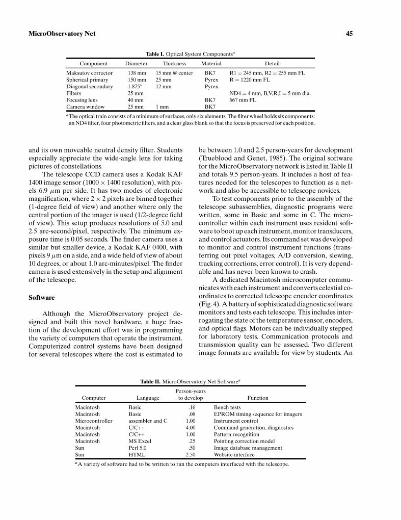
Table I. Optical System Componentsa
Component Diameter Thickness Material Detail
Maksutov corrector 138 mm 15 mm @ center BK7 R1 = 245 mm, R2 = 255 mm FLSpherical primary 150 mm 25 mm Pyrex R = 1220 mm FLDiagonal secondary 1.875′′ 12 mm PyrexFilters 25 mm ND4 = 4 mm, B,V,R,I = 5 mm dia.Focusing lens 40 mm BK7 667 mm FLCamera window 25 mm 1 mm BK7aThe optical train consists of a minimum of surfaces, only six elements. The filter wheel holds six components:an ND4 filter, four photometric filters, and a clear glass blank so that the focus is preserved for each position.
and its own moveable neutral density filter. Studentsespecially appreciate the wide-angle lens for takingpictures of constellations.
The telescope CCD camera uses a Kodak KAF1400 image sensor (1000× 1400 resolution), with pix-els 6.9 µm per side. It has two modes of electronicmagnification, where 2× 2 pixels are binned together(1-degree field of view) and another where only thecentral portion of the imager is used (1/2-degree fieldof view). This setup produces resolutions of 5.0 and2.5 arc-second/pixel, respectively. The minimum ex-posure time is 0.05 seconds. The finder camera uses asimilar but smaller device, a Kodak KAF 0400, withpixels 9µm on a side, and a wide field of view of about10 degrees, or about 1.0 arc-minutes/pixel. The findercamera is used extensively in the setup and alignmentof the telescope.
Software
Although the MicroObservatory project de-signed and built this novel hardware, a huge frac-tion of the development effort was in programmingthe variety of computers that operate the instrument.Computerized control systems have been designedfor several telescopes where the cost is estimated to
Table II. MicroObservatory Net Softwarea
Person-yearsComputer Language to develop Function
Macintosh Basic .16 Bench testsMacintosh Basic .08 EPROM timing sequence for imagersMicrocontroller assembler and C 1.00 Instrument controlMacintosh C/C++ 4.00 Command generation, diagnosticsMacintosh C/C++ 1.00 Pattern recognitionMacintosh MS Excel .25 Pointing correction modelSun Perl 5.0 .50 Image database managementSun HTML 2.50 Website interfaceaA variety of software had to be written to run the computers interfaced with the telescope.
be between 1.0 and 2.5 person-years for development(Trueblood and Genet, 1985). The original softwarefor the MicroObservatory network is listed in Table IIand totals 9.5 person-years. It includes a host of fea-tures needed for the telescopes to function as a net-work and also be accessible to telescope novices.
To test components prior to the assembly of thetelescope subassemblies, diagnostic programs werewritten, some in Basic and some in C. The micro-controller within each instrument uses resident soft-ware to boot up each instrument, monitor transducers,and control actuators. Its command set was developedto monitor and control instrument functions (trans-ferring out pixel voltages, A/D conversion, slewing,tracking corrections, error control). It is very depend-able and has never been known to crash.
A dedicated Macintosh microcomputer commu-nicates with each instrument and converts celestial co-ordinates to corrected telescope encoder coordinates(Fig. 4). A battery of sophisticated diagnostic softwaremonitors and tests each telescope. This includes inter-rogating the state of the temperature sensor, encoders,and optical flags. Motors can be individually steppedfor laboratory tests. Communication protocols andtransmission quality can be assessed. Two differentimage formats are available for view by students. An

P1: VENDOR
Journal of Science Education and Technology PP026-290012 December 26, 2000 12:30 Style file version Oct. 23, 2000
46 Sadler et al.
Fig. 4. Macintosh Resident Control Program. This software is used for testing andtroubleshooting. It allows the user access to transducers and actuators throughout thetelescope and test software by simulating control of a telescope.
8-bit GIF (graphical interchange format) image ismapped from the 12-bit raw image data to increasecontrast. The GIF format is used by commercial im-age processing programs and allows easy viewing onweb browsers. The 12 bits of raw A/D data are placedinto a 16-bit FITS (flexible image transport system).The FITS image is used by many astronomical im-age processing programs. Two independent programsaid in keeping the telescopes functioning: an optionalpattern recognition program based on the HubbleGuide Star Catalog can identify and label stars in theprocessed image and a pointing correction programcalculates telescope parameters based on pointingdata runs.
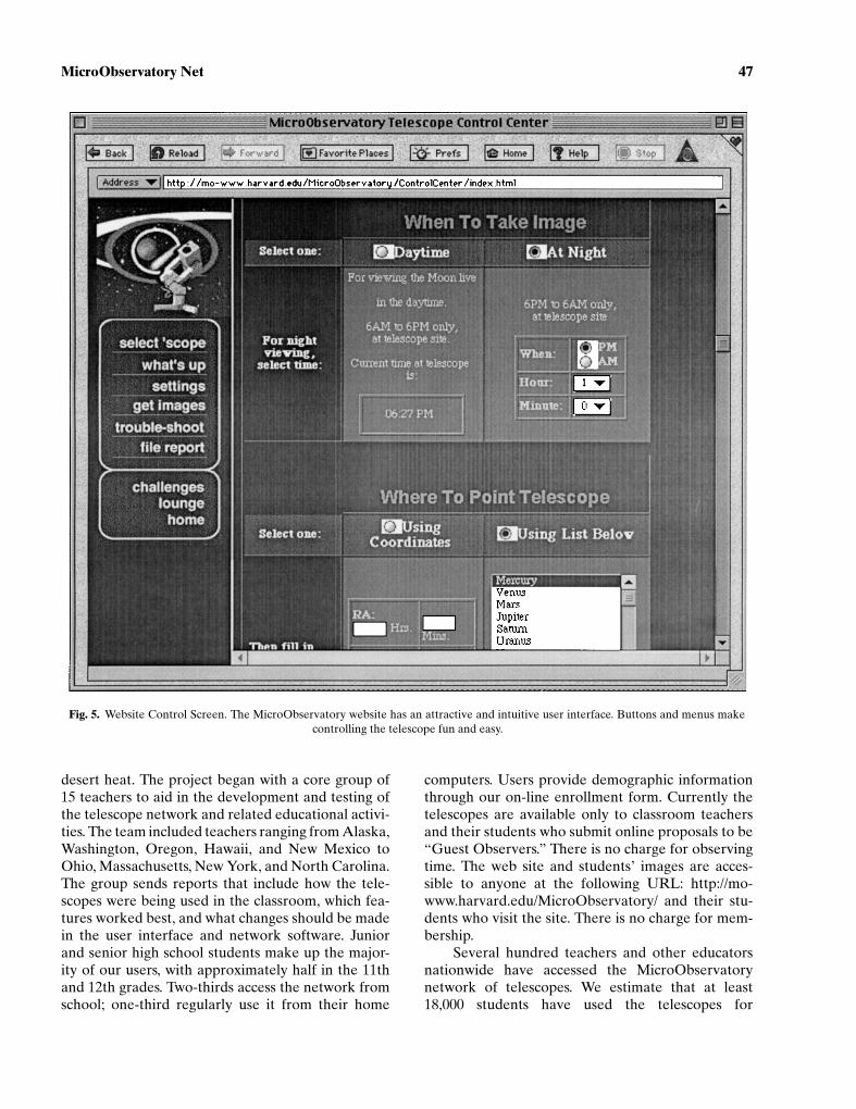
The website for the network is resident on a SunUltra 1 workstation running the Solaris operating sys-tem and the National Center for Supercomputer Ap-plications webserver. Here students interact througha graphically attractive and engaging set of web pages(Fig. 5). The site enrolls users and tracks passwordsand usage data. Students can check weather con-ditions and find which objects are visible at whichtelescopes.10 A single password enables access to alltelescopes on the network. Students have a variety ofdecisions to make; by design the MicroObservatorydoes not relieve them of authority. They can choose an
10Utilizing data from the students for the Exploration and Devel-opment of space website at http://www.seds.org
object from a list or enter its coordinates. They choosethe telescope location and which camera, filters, expo-sure time, and magnification to use. Helpful tips guideusers to acquire images successfully. Ideas for manyprojects are also available on this site. Voluntary re-porting helps to detect problems with the instrumentsand provide other feedback to the MicroObservatorystaff. Our users’ lounge features projects conductedby classes using the MicroObservatory network inunique ways. Our website keeps each image residentfor 1 week, saving the most interesting ones in its user-accessible archive. Our bulletin board is a forum fornew users to ask questions and get help from “oldhands.”
The system creates a useful header that saves in-formation about each image and the conditions un-der which it was taken (Table III). This feature allowsstudents to learn the skills that result in quality im-ages and to easily learn from pictures captured byothers. The image database can be sorted by rel-evant attributes: date, creator, individual telescope,and object.
OVERALL PERFORMANCE OF THEINSTRUMENT
The five MicroObservatories have been used on-line since November 1995, surviving ice storms and
P1: VENDOR
Journal of Science Education and Technology PP026-290012 December 26, 2000 12:30 Style file version Oct. 23, 2000
MicroObservatory Net 47
Fig. 5. Website Control Screen. The MicroObservatory website has an attractive and intuitive user interface. Buttons and menus makecontrolling the telescope fun and easy.
desert heat. The project began with a core group of15 teachers to aid in the development and testing ofthe telescope network and related educational activi-ties. The team included teachers ranging from Alaska,Washington, Oregon, Hawaii, and New Mexico toOhio, Massachusetts, New York, and North Carolina.The group sends reports that include how the tele-scopes were being used in the classroom, which fea-tures worked best, and what changes should be madein the user interface and network software. Juniorand senior high school students make up the major-ity of our users, with approximately half in the 11thand 12th grades. Two-thirds access the network fromschool; one-third regularly use it from their home
computers. Users provide demographic informationthrough our on-line enrollment form. Currently thetelescopes are available only to classroom teachersand their students who submit online proposals to be“Guest Observers.” There is no charge for observingtime. The web site and students’ images are acces-sible to anyone at the following URL: http://mo-www.harvard.edu/MicroObservatory/ and their stu-dents who visit the site. There is no charge for mem-bership.
Several hundred teachers and other educatorsnationwide have accessed the MicroObservatorynetwork of telescopes. We estimate that at least18,000 students have used the telescopes for

P1: VENDOR
Journal of Science Education and Technology PP026-290012 December 26, 2000 12:30 Style file version Oct. 23, 2000
48 Sadler et al.
Table III. Image Headera
Header: Observer’s Username: mcgrath Object: M-57 Ring NebulaDate: Thu, May 8, 1997 Greenwich Mean Time: 05:58:53Start Exposure (LMT): 10:58:53 PM End Exposure (LMT): 10:59:39 PMReference Number: mcgrath-5/9-1:55:52 Telescope’s Name: BenComments: Coordinates for this image were chosen by a list.
Filenames: SM.M-57R.05m08d22h58m14s.GIF and SM.M-57R.05m08d22h58m14s.FITSCamera: Camera: Main Exposure Time: 45.00 sec.
Filter: Clear Focus Value: 670 Zoom: OutCoordinates: Celestial: Right Ascension: 18 h 53.6 m
Declination: 33 degrees 01 minutesTerrestrial: Altitude: 26 degrees 19.9 minutes
Azimuth: 65 degrees 50.4 minutesMisc: Hour Angle: 18 h 50.9 m
Local Sidereal Time: 13:43:27Longitude: 110.95 Latitude: 31.68Mode of Operation: Batch over WWWTracking: Sidereal Finder Offsets: 320, 145CCD Temp: 278.50 Ambient Temp: n/a Circuit Temp: n/a
aThis header saved with each image file contains data about the user, object, and the state of the telescope. Having thisinformation on hand for each image makes record keeping less tedious for students and encourages the use of others’ imagesin projects.
classroom-based projects during the 3 years of theproject. However, the actual number is likely to belarger, because students (and teachers) shared theirpasswords with many others interested in using thetelescopes. (We have since upgraded the software tobe able to identify and track the progress of each userindividually.) Average monthly use runs to 500–3000
Fig. 6. Breakdown of Objects Captured. During April 1998, 582 images were requestedby MicroObservatory users. About half were chosen from a list of objects. The rest wererequested by RA and Declination. The Moon remains the most popular object, followedby a variety of Messier objects.
images taken using the web page. Images taken areabout equally split between those in a preselected listand those for which celestial coordinates must be en-tered (Fig. 6). The moon is the most popular object, inspite of its ease of viewing though binoculars or smalltelescopes. Perhaps it is students’ familiarity with itthat makes it such a favored subject for pictures.

P1: VENDOR
Journal of Science Education and Technology PP026-290012 December 26, 2000 12:30 Style file version Oct. 23, 2000
MicroObservatory Net 49
Table IV. Features of Direct and Website Controla
Feature Direct connection Website
Availability of control program From Internet or phone WWW-based interface onlyDiagnostics: monitor and test motors, communication, Available Temperatures only
encoders, crash resetAutomatic Data collection: pointing data recorder, Available Planned
pattern matching, image coordinatesCollage Generation: multiple focus and exposures times AvailableSet telescope defaults: offsets, focus, main/finder Available
alignment, lat/long, network settings, time zoneTerrestrial pointing mode, tracking off Available PlannedImage format access 8- and 16-bit 8-bit GIF 16-bit FITSSolar pointing Allowed Not allowedSafety protection: parking, re-origination Overridable AutomaticSuccessive images One at a time QueuedDelayed observation AvailableNumber of users One ManyPoint in RA and Dec, change filters, exposure, camera Available AvailableSelect between different telescope locations Manually Point and clickPointing list Planets navigation stars Popular objects w/ephemerisPattern matching to Hubble guide star catalog Available PlannedWeather conditions AvailableUser generated image library AvailableUser help: instructions, examples, challenges AvailableaUsed in these two modes, different capabilities are accessible to the user. Direct connection gives instantaneous controlto the user, essential for testing by project staff. Website control requires less knowledge on the part of the user and offersmany more aids to use.
Teachers can reserve an instrument for real-time,dedicated use, which can produce roughly an equiv-alent number of images (Table IV). This gives im-mediate control to the user. No queuing is involved.In addition, we are “hit” by some 4,000 visitors eachmonth (April 1998 figures), who request to view17,000 images per month. The heaviest usage of thesite is on Tuesdays and Fridays between the hours of9:00 AM and 5:00 PM eastern time.
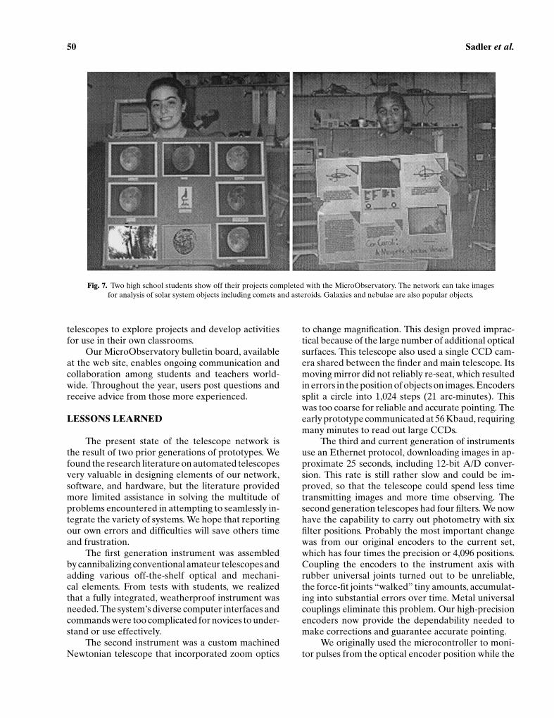
Students often use the MicroObservatory to takeimages of assigned objects to familiarize themselveswith the telescope. Students then move on to otherobjects they are studying and make them part oftheir posters or reports (Fig. 7). For example, CometHale-Bopp was an exciting subject to follow duringthe Spring of 1997. Its changing shape and bright-ness was recorded by several groups of students. Oneclass collected images contributed by others fromacross the country and from students as young asthe 5th grade to produce a computer-based movieof its changing position. Schools have also postedMicroObservatory pictures and projects at their ownweb sites. Student comments are generally very pos-itive. Many remark that this is the first time theyhave engaged in a science project that involves “realscience”: selecting a problem, collecting and inter-preting data, and presenting it to others (Filippenko,
1992). Several after-school programs have also usedour network, include Boston’s Computer Clubhouse,and a program for middle school girls in Somerville,Massachusetts.
The slew rate of the telescope is approximately2.25-degrees per second in either of the axes. Thepointing accuracy is approximately 3 minutes of arcRMS after correction. Fifteenth magnitude stars canbe captured in 15-second exposures under light-polluted conditions in Cambridge. In darker skies, weare able to reach 18th magnitude stars with approxi-mately 2-minute exposures. Maximum exposure timeis limited in several ways, through sky fog, tracking er-rors (i.e., errors in the worm gear), CCD temperature(which determines dark noise), and polar alignmenterrors (which manifest themselves as field rotation).
Teacher workshops have been held once a yearfor those interested in using the MicroObservato-ryNet with their classes. The on-line format of theseevents has proven to provide an excellent intro-duction and training ground to those new to theMicroObservatory and to this method of instruc-tion. A moderated discussion led by Linda Frenchof Wheelock College covers one topic each day.Project staff and experienced teachers provide feed-back while new users work collaboratively on projects.Between sessions teachers utilize the network of
P1: VENDOR
Journal of Science Education and Technology PP026-290012 December 26, 2000 12:30 Style file version Oct. 23, 2000
50 Sadler et al.
Fig. 7. Two high school students show off their projects completed with the MicroObservatory. The network can take imagesfor analysis of solar system objects including comets and asteroids. Galaxies and nebulae are also popular objects.
telescopes to explore projects and develop activitiesfor use in their own classrooms.
Our MicroObservatory bulletin board, availableat the web site, enables ongoing communication andcollaboration among students and teachers world-wide. Throughout the year, users post questions andreceive advice from those more experienced.
LESSONS LEARNED
The present state of the telescope network isthe result of two prior generations of prototypes. Wefound the research literature on automated telescopesvery valuable in designing elements of our network,software, and hardware, but the literature providedmore limited assistance in solving the multitude ofproblems encountered in attempting to seamlessly in-tegrate the variety of systems. We hope that reportingour own errors and difficulties will save others timeand frustration.
The first generation instrument was assembledby cannibalizing conventional amateur telescopes andadding various off-the-shelf optical and mechani-cal elements. From tests with students, we realizedthat a fully integrated, weatherproof instrument wasneeded. The system’s diverse computer interfaces andcommands were too complicated for novices to under-stand or use effectively.
The second instrument was a custom machinedNewtonian telescope that incorporated zoom optics
to change magnification. This design proved imprac-tical because of the large number of additional opticalsurfaces. This telescope also used a single CCD cam-era shared between the finder and main telescope. Itsmoving mirror did not reliably re-seat, which resultedin errors in the position of objects on images. Encoderssplit a circle into 1,024 steps (21 arc-minutes). Thiswas too coarse for reliable and accurate pointing. Theearly prototype communicated at 56 Kbaud, requiringmany minutes to read out large CCDs.
The third and current generation of instrumentsuse an Ethernet protocol, downloading images in ap-proximate 25 seconds, including 12-bit A/D conver-sion. This rate is still rather slow and could be im-proved, so that the telescope could spend less timetransmitting images and more time observing. Thesecond generation telescopes had four filters. We nowhave the capability to carry out photometry with sixfilter positions. Probably the most important changewas from our original encoders to the current set,which has four times the precision or 4,096 positions.Coupling the encoders to the instrument axis withrubber universal joints turned out to be unreliable,the force-fit joints “walked” tiny amounts, accumulat-ing into substantial errors over time. Metal universalcouplings eliminate this problem. Our high-precisionencoders now provide the dependability needed tomake corrections and guarantee accurate pointing.
We originally used the microcontroller to moni-tor pulses from the optical encoder position while the

P1: VENDOR
Journal of Science Education and Technology PP026-290012 December 26, 2000 12:30 Style file version Oct. 23, 2000
MicroObservatory Net 51
Fig. 8. Pointing errors. Telescope pointing accurate enough to put most targeted ob-jects in the center of the 1-degree field of view of the main telescope. Errors in pointinggreater than 6 arc-minutes RMS result from calibration of newly constructed or repairedinstruments.
telescope motors were running. This technique pro-duced mystifying errors in our second generation tele-scope. The major contributor to pointing inaccuracywas the telescope’s tendency to continue to move afterthe motors stopped it in a new position, either becauseof subtle imbalance issues or wind load. When the mi-crocontroller “looked away”—just like an adult lift-ing his gaze from a typical 4-year-old—the telescopeinstantly took the opportunity to misbehave (just as4-year-olds do). The microcontroller did not recordthis subtle drift. We have since incorporated countersthat continually “baby sit” and monitor pulses fromeach optical encoder.
Slewing algorithms had to be developed to accu-rately point the telescope to reduce overshoot. Ourmotors start slowly to accelerate the instrument andslow gradually. All objects are approached from onlyone direction in RA and Dec, eliminating inaccuraciesdue to gear lash.
With several telescopes having different physicalparameters, we found that pointing was problematicespecially when switching between telescopes. Forsimplicity, each instrument now utilizes its own setof internal coordinates governed by its optical breaksand encoders. Commands to the telescope for point-ing to a particular RA and Dec must take into accountany mechanical and optical differences between in-struments as well as refraction effects. We developeda model for each telescope using a diagnostic pointingroutine to identify the varying mechanical and opti-cal characteristics of each instrument. This diagnos-tic pointing model solves for 10 variables: RA and
declination fiducials, encoder amplitude and phase;polar altitude and azimuth; collimation; and orthogo-nality. Typically, each telescope is calibrated using 100to 150 observations of guide stars; pointing errors arethen minimized by solving for these telescope correc-tion parameters (Fig. 8). Adjusting for differences inphysical parameters by using software has enhancedthe interchangeabilty of our instruments and givenus insights into the variations while attempting tobuild identical telescopes. Calculating these param-eters over time identifies which telescopes exhibit themost stable characteristics and which need attention(Fig. 9). This indirect measurement of telescope per-formance reduces the need for invasive or specializedmanual testing procedures. Such diagnostic softwaretools, coupled with instrument sensors, help to reducedowntime (Monahan et al., 1995).
Of course, any stellar object can be used for sucha pointing run, but because of their even distribu-tion, unique brightness, and distance from other stars,the 57 navigation stars of the Nautical Almanac workwell.11 Our automated program observes all the visi-ble navigation stars several different times and auto-matically identifies their position in the image. Thesedata are then imported into the correction model,which runs in Microsoft Excel. It comes as no surprisethat when we disassemble a telescope and put it backtogether again, certain parameters remain the sameif we did not touch or adjust those components. Thisexperience gives us an idea of what the variability in
11Published yearly by the US Naval Observatory.

P1: VENDOR
Journal of Science Education and Technology PP026-290012 December 26, 2000 12:30 Style file version Oct. 23, 2000
52 Sadler et al.
Fig. 9. Telescope Orthogonality and Collimation Parameters. The orthogonality of each ofour telescopes shows similarity among instruments and stability over time. The collimationcorrection parameters of telescopes Annie and Cecilia are stable and small; those for Ben andDon are larger and vary considerably, suggesting that the optical mounts may need attention.
machining and assembly can be for these small tele-scopes. One can see from Fig. 9 that the orthogonalityof each telescope is similar in value and reliability,while the collimation varies from telescope to tele-scope. The large range in collimation parameter oftelescopes Ben and Don suggest that there is move-ment somewhere in the optical train, which has sincebeen attended to.
EDUCATIONAL FINDINGS
Although the telescopes were used in a very widevariety of ways in the classroom, almost all activi-ties fell into one of four categories: simple observa-tion, quantitative studies, student projects, and ma-ture integration into the curriculum. Here are someexamples.
• Simple Observation. Many students used thetelescopes simply to “see what’s out there,”starting with the moon, the constellation oftheir birth sign, or other familiar object, andcontinuing to the moons of Jupiter, nebulae,and distant galaxies. Some teachers used thetelescopes as a supplement to their textbooks,encouraging students to take their own imagesrather than refer to the text.• Quantitative Studies. More confident teachers
guided students through measurements usingthe telescopes. For example, students used thetelescopes to estimate the speed of an aster-oid or comet (Hyakutake, Hale-Bopp). Othersused the telescope to determine the distanceto the moon, the size of the moon, the size ofcraters on the moon, and so on from variousobservations.
• Student Projects. Some students used the tele-scopes as the centerpiece of a broader project.For example, one high school girl wrote a re-port on the life and death of stars, using thetelescopes to document various stages in astar’s life cycle, imaging objects such as theOrion nebula, the Ring nebula, and the CrabNebula.• Mature Integration into the Curriculum. It is a
rare teacher who integrates the telescopes intoa carefully planned theme. An interesting ex-ample was a middle school teacher who usedthe telescopes in a project on time: Studentsfirst gathered and discussed old family docu-ments, then they studied tree rings and othernatural records of time, and finally they usedthe telescopes to peer millions of years into thepast by imaging distant (and therefore ancient)galaxies.
Importance of Ownership
One factor was found to overwhelm all other con-siderations in the use of the telescopes, and far ex-ceeded our expectations—namely, the self-describedsatisfaction that came from the learner’s control overthe telescopes and “ownership” of their images. Theimportance of this sense of ownership was reportedover and over by teachers and by the students them-selves. Because of this sense of control, students weremotivated to carry out fairly complex projects. In thewords of one teacher:
My students seem to more fully grasp the contentand meaning of astronomical images when they canfeel some ownership of the image (as they do withMicroObservatory). Generally speaking, I find that

P1: VENDOR
Journal of Science Education and Technology PP026-290012 December 26, 2000 12:30 Style file version Oct. 23, 2000
MicroObservatory Net 53
today’s junior high students need a great deal of prac-tice with following directions, and activities that helpto expand their attention spans are very useful andimportant. MicroObservatory has been an excellenttool for implementing such activities. (T.S., teacherfrom Florida)
This finding was in fact a surprise. We hypothe-sized that students might feel distanced or alienatedfrom remotely based instruments on the Internet. Forexample, students cannot directly see the telescopewhile it is moving; the traditional tactile and kines-thetic connection that binds scientist to instrumentwas lacking.
The Ability to Fail Instructively
One possible reason for the above finding is thatstudents’ physical connection to the instrument ap-peared to be less important than their connection tothe result—the final image. Here, the most importantfactor that appears to connect students to their resultsis the opportunity to fail instructively. If you do nothave the opportunity to fail, then you cannot be saidto succeed. Pride in the final image appeared to bea function of the fact that not every image came outperfectly; several factors, from clouds to improper ex-posure times, intervened. This is probably similar tothe addictive quality of videogames or of scientific ex-perimentation itself: a measure of uncertainty in theoutcome is a powerful attractor.
One feature that helped students to improvetheir skill level was the ability to inspect other users’images, including information on how they were ob-tained, such as exposure time, filters, and so forth.This enabled students to learn from others’ mistakesor to contribute the insights gained from their ownfailures to the community. In fact, we found that stu-dents (and teachers) actively inspected other users’work, and tried to learn from their successes as wellas failures. Advice is given freely: “The object she waslooking for wasn’t above the horizon yet” or “Thewrong filter was used.”
Authenticity of Activity Promotes Learning
We observed that in the course of carrying outactivities, students were prompted to ask themselvesquestions—almost as though they were thinking outloud—essential to completing the work. For example,“If I use a filter, should I increase the exposure time?By how much?” Or, “Can I predict how the shadowof the Earth’s surface will move across the Moon in
this lunar eclipse?” These self-addressed questionsgave students a chance to access, construct, and re-fine their own mental models of what was going on asthey used the telescopes. This authenticity of activityappeared to be a powerful catalyst for learning. Evenmore important, students reported that quantitativestudies with the telescopes helped to motivate themto use math. “Last year,” said one high school girl, “Ithought, ‘Why am I learning this math?’ But now Iactually use it!” Also, the visual nature of this projectprompted students to create—and maintain—Websites showing their work with the telescopes.
Equity of Access
An important goal of MicroObservatory Net wasto use the Internet to enable previously underservedgroups to gain access to powerful scientific instru-ments. Our observations strongly confirmed that thisbenefit is substantial. For example, the telescopeswere accessed by a group of Native American childrenfrom a shopping mall in New Mexico, led by a sciencemuseum educator. Students at an inner-city school inBoston were astounded that they could image galax-ies themselves; many had never seen more than fivestars in the night sky. A high school girl asked what thedark areas on the Moon represented; she explainedthat she was legally blind, and had never before real-ized that the Moon had features. Equity of access, webelieve, is one of the most important features of theMicroObservatory telescopes.
Change in Teacher’s Classroom Practice
As might be expected, teachers reported a strongshift away from “teaching the textbook” and more to-ward hands-on projects in which they could guide stu-dents. Most of the core teachers had wanted to serveas a mentor to their students, but had not previouslyhad a mechanism for doing this. The telescope net-work provided a mechanism for moving teachers to anew level of involvement with their students.
WHERE DO WE GO FROM HERE?
We plan to implement several improvements inour telescopes. The current firmware (microcontrollerPROM software) allows pointing in only one axisat a time. Improvements would allow both axes‘tomove at once. By allowing A/D conversion and im-age transmission during slewing, throughput could be
P1: VENDOR
Journal of Science Education and Technology PP026-290012 December 26, 2000 12:30 Style file version Oct. 23, 2000
54 Sadler et al.
greatly increased. A smaller main camera CCD couldperform well, and at a lower cost. Encoders in alti-tude and azimuth would aid in polar alignment. Addi-tional sensors (humidity, rain, and cloud) would helpin troubleshooting problems. Our current clutchesassembled from Lexan are too temperature sensitive;a more reliable clutch material should be utilized.Nonsealed motors have a tendency to leak oil overtime, which coats key surfaces and requires manualcleaning.
We have seen that the telescope network per-forms well over the World Wide Web. It offers op-portunities to students to conduct projects and forteachers to integrate original images into their sciencecurricula. Students have followed the suggestions ofresearchers in studying changes in position of comets,asteroids, and planets; and of the brightness of stars(Sadler et al., 1999). Remote instrumentation of manytypes could use the Web to provide opportunities andexperiences that are too rarely available to the na-tion’s youth.
We currently are working on supplementing ex-isting physical science curriculum materials to supportstudents’ online telescope projects. From the GroundUp encompasses five investigations that use student-acquired images to teach basic concepts in the areasof orbital motion, light and color, thermodynamics,size and scale, and the nature of scientific inquiry.Each set of materials focuses on the exploration ofa concept that is central to the National Science Ed-ucation Standards at the middle or high school level.Students can then follow up with their own inquiry-based project that can also involve collaboration witha research scientist. We plan to evaluate the contribu-tion to student engagement and success when pursu-ing their own projects. Using the approach of scaffold-ing initial engagement, students will first investigatea challenge in a topical area that is currently popular(e.g., a new comet) or one in which students have con-sistently been successful in the past (e.g., the moon’scraters).
Our hope is to grow to a larger network of Mi-croObservatory telescopes, put them in many more lo-cations, especially in distant time zones, and use themin a variety of settings, from elementary schools to col-lege courses. We feel we have solved the multitude ofproblems involved in developing this fascinating ed-ucational tool by building hardware ideally suited toeducational use and by writing software and supportmaterials that make taking pictures of the heavenseasy for even the most amateur of astronomers. Welook forward to the day when every student with an in-terest in the sky can have the experience of controlling
a telescope and imaging the object of his or her choice.We feel indebted to the professional instrumentationcommunity for many solutions to our problems andhope to repay the debt by enticing youngsters to par-ticipate in the exploration of the sky.
ACKNOWLEDGMENTS
Scientists from the Harvard-Smithsonian Centerfor Astrophysics have contributed their ideas and sup-port for this project: Sallie Baliunas, Bruce Gregory,Nat Carlton, John Geary, Owen Gingerich, JoshGrindlay, Sam Palmer, Irwin Shapiro, and CharlesWhitney. Linda French has led our on-line institutes.Science Education Department staff has contributedtheir ideas and feedback: Harold Coyle, Susan Roude-bush, Scott Balderson, and Judith Peritz. MarcusLeiberman and Annette Trenga have carried out as-sessment activities. Josh Freeman developed our pat-tern recognition software. Russ Genet from Fair-born Observatory and Tom Mathis from Carina Soft-ware have given us valuable help. NIH Image creatorWayne Wasban has aided us as well. Teachers fromaround the country have used the telescopes withtheir students; among the most deeply involved are:Sandy Cameli, John Everhart, Joan Hall, Marti Lynes,Sheila McGrath, Bruce Mellin, Clark Neily, PaulNiles, Robert Ochs, Mark Petricone, Mike Richard,Bruce Seiger, and Larry Weatherwax. This work issupported by the National Science Foundation (RED9155723, RED 9454767, and ESI 9730351) for whichour program officers, Nora Sabelli, Andy Molnar, andGerhard Salinger have been very supportive. We havealso been aided by support from Apple Computer,Kodak, Minolta Corporation, Nasa, and The Smith-sonian Institution which we deeply appreciate.
REFERENCES
Baliunas, S. L., Donahue, R. A., Loeser, J. G., Guinan, E. F., Genet,R. M., and Boyd, L. J. (1987). Broadband photometry of brightstars: the first year of APTS at the F.L. Whipple observatory. InHayes, D. S., Genet, R. M., and Genet, D. R. (Eds.), New Gen-eration Small Telescopes, Fairborn Observatory, Mesa, AZ,pp. 97–116.
Boyd, L. (1985). Automating a telescope. Byte 10(July): 27.Clark, G., and Jashow, R. (1994). Dial a galaxy: A Mount Wilson
program for amateur astronomers. Mercury 23: 24–25.Filippenko, A. (1992). The scientific potential of automatic CCD
imaging telescopes. In Filippenko, A. (Ed.), Robotic Telescopesin the 1990s, Astronomical Society of the Pacific, San Francisco,pp. 55–66.
Genet, R. (1992). Robotic telescope networks. In Filippenko, A.(Ed.), Robotic Telescopes in the 1990s, Astronomical Societyof the Pacific, San Francisco, pp. 241–247.

P1: VENDOR
Journal of Science Education and Technology PP026-290012 December 26, 2000 12:30 Style file version Oct. 23, 2000
MicroObservatory Net 55
Harris, C. (1986). Silicon eye: A CCD imaging system. Sky & Tele-scope 71: 407–411.
Huchra, J. (1988). Silicon eyes. Technology Window. A Publicationof the Office for Information Technology 2(April): 1–3.
Kilbrick, R., Conrad, A., and Perala, A. (1998). Through the farlooking glass: Collaborative remote observing with the W.M.Keck Observatory. Interactions May/June: 32–39.
Mallama, A. (1996). Automation of a commercial astronomicaltelescope. Publications of the Astronomical Society of the Pa-cific 108(Jan): 110–111.
McCullough, P. R., and Thakkar, U. (1997). Stardial: An as-tronomical camera on the world wide web. Publicationsof the Astronomical Society of the Pacific 109(Nov): 1264–1268.
McCord, T. B., Snellen, G., and Paavola, S. (1972). The MIT au-tomated astrophysical observatory. Publications of the Astro-nomical Society of the Pacific 84(Feb): 220–224.
Monahan, C. M., Paterson-Hine, F. A., and Iverson, D. L. (1995).Automated telescope monitoring and diagnosis. In Henry, G.,and Eaton, J. (Eds.), Robotic Telescopes, Astronomical Societyof the Pacific, San Francisco, pp. 120–128.
O’Connor, E. (1994). Remote access astronomy. Science Teacher61: 48–52.
Pennypacker, C. (1997). Why do scientists want teachers and stu-dents to do research? National Conference on Student & Sci-entist Partnerships Conference Report. TERC, Cambridge,Massachusetts, pp. 48–52.
Philip, A. G. D., and Hayes, D. S. (1992). Some thoughts on anautomated imaging telescope. In Adelman, S., Dukes, R., andAdelman, C. (Eds.), Automated Telescopes for Photometry andImaging, Astronomical Society of the Pacific, San Francisco,pp. 91–99.
Ratcliffe, M. (1994). Remote astronomy: Bringing Mount Wilsonto you. Sky & Telescope 88: 38–41.
Sadler, P. M., Gould, R., Brecher, K., and Hoffman, B. (2000). As-tronomical experiences using Internet-accessible remote in-strumentation. In Jacobson, M., and Kosma, R. (Eds.), In-novations in Science and Mathematics Education: AdvancedDesigns for Technologies of Learning. Erlbaum, Mahwah,New Jersey, pp. 259–286.
Trueblood, M., and Genet, R. (1985). Microcomputer Control ofTelescopes. Willmann-Bell, Inc, Richmond, Virginia.
Zulstra, A. A., Wallander, A., Kaper, L., and Rodriguez, J. A.(1997). Remote observing at the ESO NTT and CAT tele-scope. Publications of the Astronomical Society of the Pacific109: 1256–1263.


![SpiraTest/Team/Plan Automated Unit Testing Automated Testing Integration Guide.pdfThe .NET class is marked as an NUnit test fixture by applying the [TestFixture] attribute to the class](https://img.pdfslide.us/doc/110x75/5e7312b941386878b52d74b5/spiratestteamplan-automated-unit-automated-testing-integration-guidepdf-the-net.jpg)