Embed Size (px)
Citation preview

TEK
MICROCOMPUTERDEVELOPMENT
PRODUCTS
System Peripherals 51Accessories and Workshops 53
CONTENTS
387238743876Z80AZ80SZ8001Z8002TMS9900SSP9900SSP99891802
...with more to come
Tektronix Microcomputer DevelopmentProducts offer the broadest range of qualitymultiple microprocessor support availabletoday. Tektronix won't lock you into onemicroprocessor family or vendor. Plus, everyTektronix MDL is backed with over 30 yearsof design experience. We test our Development Labs thoroughly to ensure performance and reliability. Each one providescomplete development capability and theTektronix commitment that guaranteesyou'lI keep abreast of the fast pacedmicroprocessor technology.
Cali your local specialist today to find outmore about the Tektronix 8550 MDLSystems.
MDL Now Supports8088/87 680008086/87 681208085A 68008080A 68018048 68028049 68038035 68088039 68098021 6809E8022 F88041A 3870
Trigger Trace Analyzer 46Software Toois and Lands 48High Level Language 49
Emulators Processor andPrototype Control ProbeSupport Packages . 45
Microcomputer Development Labs8550 Microcomputer Development Lab 388560 Multi-User Software Development Lab . 408540 Microcomputer Integration Unit 42
37

TEK MICROCOMPUTERDEVELOPMENT LAB
Three Basic Design EnvironmentsMicrocomputer design is currently performed inthree basic work environments. These are thesingle-user environment, the multi-user environment, and the host computer environment. TheTektronix 8500 Series of Microcomputer Development Labs offer a full complement of development tools for ail three microcomputer designenvironments. In each case, the most advancedtechnology available has been incorporated intoan 8500 Series Microcomputer Development Labthat gives maximum performance in its intendedsetting. In this manner, Tektronix provides unmatched support for both microcomputer software development and hardware/software integration, no matter where it occurs.
The 8550 Microcomputer Development Labfor the Single User EnvironmentThe 8550 is a self-contained Microcomputer Development Lab that gives complete support toone user at a time. Important features of the8550 Microcomputer Development Lab include:Guide, an optionally-invoked, menu-driven approach to system operation; high level languageand assembly support with symbolic debuggingfor both 8-bit and 16-bit chips; emulation to instail developed software in prototype hardware;and the powerful real-time debugging tool: theTrigger Trace Analyzer for 8-bit and 16-bitdesigns.
The 8560 Multi·User Software DevelopmentUnit for the Multi-User EnvironmentThe 8560 is a full microcomputer software development lab that supports up to eight separate
38
work stations. Multi-user support is accomplishedusing the 8560's powerful TNIX· operating system, tailored specifically for team-oriented microcomputer development work. TNIX includes afast, flexible filing system for effective data basemanagement, advanced command capability forstreamlining software development tasks, andseveral optional utility packages such as textprocessing. The 8560 uses a 16-bit CPU to control system resources. Software work stationsconsist of CRT terminais and the 8540 Integration Unit which has full emulation and debuggingcapability. Or, the 8550 can be used forhardware/software integration.
The 8540 Integration Unit for the Host Computer Environmentln the host computer environment, a general purpose computer is used to support microcomputer-based design projects. The host computer'stimesharing capability allows a number of designers at CRT terminais to simultaneously usethe computer's facilities. Each designer has access to microcomputer development tools suchas editors, assemblers, and compilers. The 8540Integration Unit extends the host computer's microcomputer development support to include thetask of hardware/software integration. While the8560 or other host computer supports the software development task, the 8540 is used to integrate, test and debug the prototype hardware.The 8540 uses real-time emulation, a fast and efficient integration technique that employs an em-
'TNIX is a trademark 01 Tektronix. TNIX is a derivation 0/ BellLab's UNIX Operating System Version 7.
ulator processor identical in function to the onetargeted for the prototype. For added real-timedebugging, a 62-channel Trigger Trace Analyzeris available as an option.
8550 Microcomputer Development LabThe 8550 is a completely self-contained microcomputer development system that gives fullsupport to both software development andhardware/software integration. For software development, the 8550 provides a wide range ofsophisticated tools for fast, effective code generation. These include many 8-bit and 16-bit assemblers that support symbolic debugging, produce relocatable code and have powerful macrocapabilities. High-Ievel language support includes both Pascal, Microcomputer DevelopmentLab/IL compilers, and an enhanced form of BASIC with many microcomputer-oriented extensions. A line-oriented editor is included and anoptional Advanced CRT-Oriented Editor.
The 8550 provides features carefully designed tosave you time while increasing your efficiency.One feature reduces the time lost by new usersas they learn to operate the system. To bringnew users quickly up to speed, the 8550 includes a special menu-driven program calledGuide, which offers a friendly interface for thebeginner, but does not hinder the advanceduser. Guide employs a series of menus thatshows the user a well-documented pathwaythrough system operations. At any time, the usercan escape Guide and return to the conventionalcommand format. In this way, the new usersbenefit, but not at the expense of the advanceduser.
When you're experienced enough to move beyond Guide, you'lI find a whole set of advancedfeatures at your commando You'lI be able tobuild special command files that are invokedthrough a few simple keystrokes to automaticallyexecute system routines. The system will beworking for you instead of you working for thesystem.
Program Development and Data FileManagementThe 8550's DOS/50 operating system helps thedesigner manage ail phases of program development and debugging. DOS/50 supervises general 1/0, file creation and maintenance, programassembly and compilation, program execution,monitoring and debugging.

TEK
8550
Multiple Microprocessor Support
ln-Circuit Emulation
Real-Time Prototype Analysis
Assembly and HLL SupportThe 8550'5 assembler packages provide fullcode-development support for a wide range ofS-bit and 16-bit chips. Powerful macros allow thedesigner to access frequently used sets of codeby name reference. The linker, working with therelocating features of the assembler, links andlocates multiple-code segments into a completeexecutable program. Additionally, a conditionalassembly feature allows the designer to customize the final program by testing conditions todetermine which of certain code segments are tobe assembled into the final program. ExtensiveEnglish language diagnostics provide easy-tounderstand error messages and locate the line inwhich the error has occurred. When assembly iscompleted, the assembled code is stored on diskin a binary format file.
For selected chips, high level language support isavailable to increase your development power.One language offered is Microcomputer Development Lab//L, a BASIC-Iike language created specifically for microcomputer design. Another isPascal, with its structured approach that readilyadapts to microcomputer software development.For both languages, Tektronix has added a fullcomplement of extensions that allow code manipulation at the microprocessor level, includingaccess to microprocessor interrupt vectors, individual memory locations and 1/0 ports.
Ali software tools and files are managed by ahighly flexible filing system that allows nesting toany level a project requires. Included are a linkerand library generator to assist in modular codedevelopment. The 8550'5 two 1 megabyte floppydisks provide more than adequate mass storage.
Une Printer Spooling Keeps the SystemConstantly AccessibleOne drawback of many development systems isthat the system is not available to Vou when theprinter is outputting a program listing. The systemCPU directs ail its attention to the operation and
cannot service other system operation. Sinceprogram printouts may be frequently required,this can mean a considerable 1055 in productivity.
The 8550 solves the problem through line printerspooling, which keeps your CRT fully operationaleven while printing is in progress. You haveunhindered access to the system, resulting in asignificant productivity increase.
Time-Saving Debugging TooisThe 8550 gives vou Real Emulation for each of itsmodular emulator processors. This means thatthe emulator processor is truly identical in function to the processor targeted for your prototype.With no restrictions on interrupts, no reservedcode space and no hidden hardware requirements. It also means true real-time emulation upto the processor's full specified operating speed.No need for stretched c10ck pulses or added waitstates that cause hidden timing bugs in your finalproduct.
For 16-bit and S-bit designs, the Trigger TraceAnalyzer uses a high speed trace buffer capableof working with bus cycle speeds up to S MHz.The buffer is 62 bits wide to capture 16 data bits,24 address bits, 14 emulator-dependent bits, andS-bits from external hardware. Up to four independent triggers can be combined in both logical andsequential combinations to form a breakpoint ordata storage trigger. The individual triggers themselves can be defined from a combination of busdata, pass delay counters, and an external qualifier. Each trigger can also initiate its own externaloutput to trigger other instruments such as oscilloscopes and lagic analyzers.
The Trigger Trace Analyzer offers a powerful anddiverse set of debugging operations. For instance, the real-time length of an interrupt serviceroutine can be measured while simultaneouslycounting the number of assertions from a secondinterrupt source. Or, the maximum depth of astack-during-program execution can be determined. To optimize code performance, the reador writes within any given address range can beisolated and counted, thus identifying heavilyused areas for code optimization.
Real Time Emulation - Three EmulationModesAfter an error-free assembly listing has beenobtained, the resulting object code may be executed in system emulation Mode 0 on the optionalemulator processor. The emulator processor isidentical in function to the microprocessor thatwill finally be installed in the user's prototype.Execution is performed under control of the debug system; during execution, program steps canbe traced, software breakpoints can be set, andmemory can be examined and changed as required. Should an error be discovered, that portion of the program can be corrected at thesource level using the text editor. It then can bereassembled and executed again. This procedurecontinues until the program is correct.
After the software has been debugged, it may beexercised on the prototype circuitry in the partialemulation mode (Mode 1). During partial emulation, control may be released from the 8550 to theprototype in stages. The development softwareruns using 8550 memory space and prototype 1/0and c1ock. The 8550 memory mapping featureallows code to be gradually mapped over to theprototype's memory in manageable blocks.Throughout partial emulation, the user has accessto prototype circuitry through the debugging system. This allows the user to trace, set beakpoints,examine and change memory and registercontents.
MICROCOMPUTERDEVELOPMENT LAB
ln full emulation (Mode 2), the program is run onthe prototype, but program execution is still underthe complete control of the debug system. Ali VOand timing functions are directed to the prototype; ail memory has been mapped over to theprototype; and only the prototype control probe isstill in place, emulating the target microprocessor.Although the prototype is effectively free-standing, the user may still direct program activity fromthe 8550.
Transform the 8550 into a general purposecomputerOften, vou will have professional and personalpursuits besides microcomputer design that lendthemselves to computerization. So Tek has madeit easy to transform the 8550 into the realm ofgeneral purpose computing.
It's done through an operating system packagecalled RT-11/5O, which Tek offers as an 8550option. RT-11/5O opens the door to a wide rangeof third party applications software. And with it,the 8550 can quickly become a project management computer, an engineering computer, a personal computer or a small business bookkeeper.Many other useful, cost-effective applications arepossible with the addition of RT-11/50.
8550 CHARACTERISTICSThe 8550 consists 01 an 8301 Microprocessor DevelopmentUnit and an 8501 Data Management Unit.
8301 MICROPROCESSOR DEVELOPMENT UNIT
Dimensions mm ln
Width 430 17.0Height 280 11.0Depth 585 23.0
Weight kg lb
Net 27.0 60.0
ENVIRONMENTAL CHARACTERISTICSOperatlng Temperature - +32"F to +122"F (O"C to+50"C).Humidlty - 90% at +86"F to + 140"F (+30"C to +60"C).Altitude - Operating: 0 to 4500 m (15,000 ft). Storage: 0 to15 000 m (50,000 ft).
AC POWERLine Voltage Ranges - 115 V ac (90 V ac to 132 V ac);230 V ac (180 V ac to 250 V).Line Freqancy Range - 48 to 66 Hz.
8501 DATA MANAGEMENT UNIT
Dimensions mm inWidth 424 16.8Height 267 10.5Length 597 23.5
Welght kg lb
Net 25.0 55.0
ENVIRONMENTAL CHARACTERISTICSOperatlng Temperature - +50"F to +104"F (+10"C to+40"C)Humldlty - 20% to 80% relative noncondensingAltitude - Operating: 0 to 2500 m (8,000 ft) Derate maximumoperating temperature by + 1"C for each 300 m above2400 m. Storage: 0 to 15 000 m (50,000 ft).
AC POWERLlne Voltage Rang.s - 115 V ac (90 to 127 V RMS);230 V ac (180 to 250 V RMS).Llne Frequency Range - 50 Hz ± 1% or 60 Hz ± 1%.Overload Protection - Automatic current limit foldback.
FLEX DISK CHARACTERISTICSEncodlng - IBM compatible single or double density. Formatmust qualify as lollows: MFM sectors = 256 bytes. FM sectors - 128 bytes.Diskette Type - Single or double sided, soft sectored.Capaclty - Double sided, double density: 1,021,696 bytes.Single sided, double density: 509,184 bytes. Single sided, single density: 256,256 bytes.
Order 8550 Microcomputer DevelopmentUnit $17,000
39
TEK MULTI-USERSOFTWARE DEVELOPMENT LAB
8560
256 kb Memory Expandable to 1 Mb
Multi-Chip Design Support for up to 8 Users
TNIX Operating System
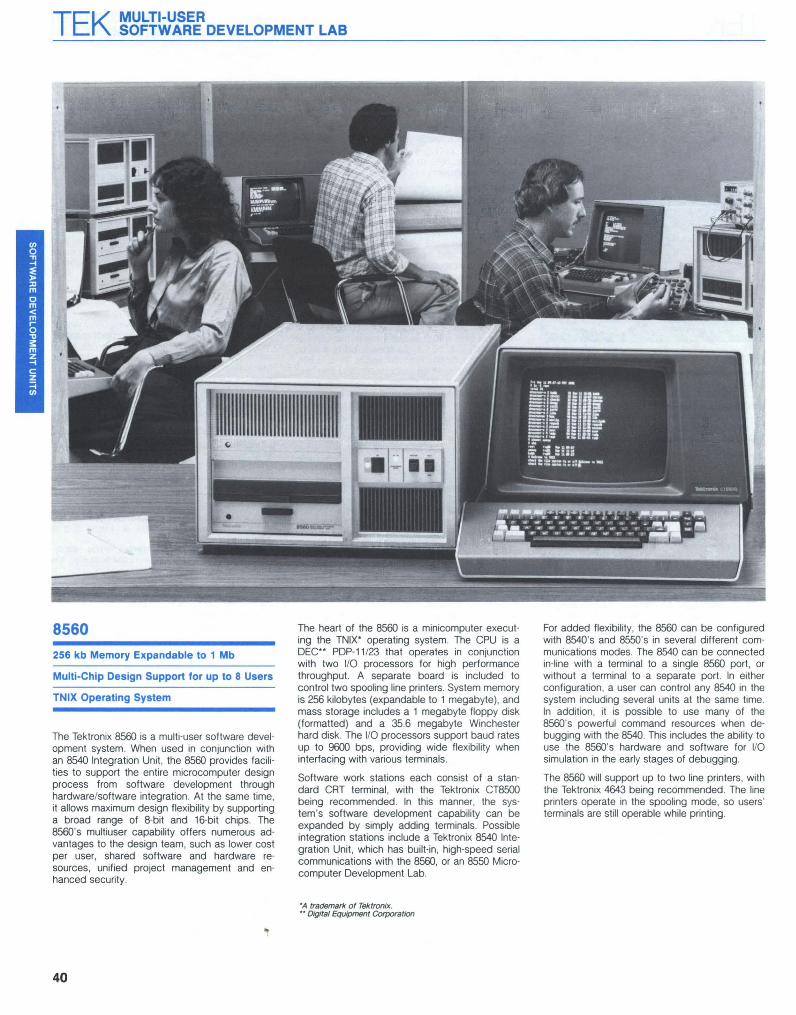
The Tektronix 8560 is a multi-user software development system. When used in conjunction withan 8540 Integration Unit, the 8560 provides facilities to support the entire microcomputer designprocess from software development throughhardware/software integration. At the same time,it allows maximum design flexibility by supportinga broad range of 8-bit and 16-bit chips. The8560's multiuser capability offers numerous advantages to the design team, such as lower costper user, shared software and hardware resources, unified project management and enhanced security.
40
The heart of the 8560 is a minicomputer executing the TNIX· operating system. The CPU is aDEC·· PDP-11123 that operates in conjunctionwith two 1/0 processors for high performancethroughput. A separate board is included tocontrol two spooling line printers. System memoryis 256 kilobytes (expandable to 1 megabyte), andmass storage includes a 1 megabyte floppy disk(formatted) and a 35.6 megabyte Winchesterhard disk. The 1/0 processors support baud ratesup to 9600 bps, providing wide flexibility wheninterfacing with various terminais.
Software work stations each consist of a standard CRT terminal, with the Tektronix CT8500being recommended. In this manner, the system's software development capability can beexpanded by simply adding terminais. Possibleintegration stations include a Tektronix 8540 Integration Unit, which has built-in, high-speed seriaicommunications with the 8560, or an 8550 Microcomputer Development Lab.
·A trademark of Tektronix.•• Digital Equipment Corporation
For added f1exibility, the 8560 can be configuredwith 8540's and 8550's in several different communications modes. The 8540 can be connectedin-Iine with a terminal to a single 8560 port, orwithout a terminal to a separate port. In eitherconfiguration, a user can control any 8540 in thesystem including several units at the same time.ln addition, it is possible to use many of the8560's powerful command resources when debugging with the 8540. This includes the ability touse the 8560's hardware and software for 1/0simulation in the early stages of debugging.
The 8560 will support up to two line printers, withthe Tektronix 4643 being recommended. The lineprinters operate in the spooling mode. so users'terminais are still operable while printing.

TEK
TNIX Operating SystemRunning under the TNIX operating system, the8560 can include a wide variety of softwaredesign tools offered by Tektronix. These includemacro assemblers and compilers for both 8-bitand 16-bit chips; Iinkers/loaders to combine object files into executable object code; and severaltypes of editors including an advanced screenoriented version. Also there is a text processingpackage that can be a valuable aid to softwaredocumentation, and a number of utility packagesto expand system capabilities in various ways.
The 8560's TNIX operating system was deriveddirectly from Bell Laboratories' UNIX OperatingSystem; an operating system that has gainedwidespread acceptance throughout the computer world. TNIX takes ail the proven advantages ofUNIX and applies them directly to the specifictasks required during microcomputer design.
TNIX includes a hierarchical file managementsystem that greatly enhances the ease andspeed of file operations. It is organized with a"root" directory on top and descending levels ofsubdirectories underneath. Each level may contain either files or directories that point to morefiles on a lower level.
TNIX also provides a sophisticated system ofread/write protection that guards user materialbut retains the interfile access needed to enhance productivity. Each user can specify read,write, or execute protection on any of threelevels: a user, a group of users, or ail users. In thisway files can first be completely protected whileunder initial development, then released to thoseworking on related sections of the program, andfinally released to the entire project after debugging is completed. To enhance communicationbetween users, TNIX includes a system of electronic mail that lets team members send messages to one another. It also allows direct communication between two users at separateterminais, plus the ability to broadcast a singlemessage to ail terminais. These various communications modes can be a valuable asset to bothteam members and team management.
Powerful Command Structures SimplifySoftware Development and IntegrationTNIX uses an extremely flexible command structure, one that permits effective programming atthe expert level as weil as the beginner level. In ailcases, TNIX commands let the user concentrateon software design instead of system manipulation. One simple but very powertul TNIX command operation is pipelining. It permits the outputof one command to act as the input to another.At an even higher level of refinement, TNIXpermits the construction of intelligent commandfiles that perform varying functions depending onthe number or value of parameters being passed.
Other TNIX command features include keyboardread-ahead which lets the user type in commands as fast as possible, without waiting forprevious commands to finish. Another time saveris multitasking, which lets the user concurrentlyrun several jobs that may be at different levels ofpriority. For instance, a compilation couId bedetached and run in the background while theuser started to edit a new source file. This featuresaves time while making more intelligent use ofthe system's resources.
To minimize system learning time, TNIX includes aspecial user interface called GUIDE, that combines the best features of both menu-driven andcommand-driven systems. GUIDE lets the liserselect any system operation from a menu display,and then automatically pertorms the operation. Atany time, the user can exit from GUIDE andescape back to TNIX and its direct entry command format. This way, the user can employ themenu as a learning tool, but is able to depart tothe regular TNIX command format for more sophisticated operation.
Automatic Module Combination CutsComplexityDuring debugging, software modules that exhibitdefects must have corrections entered into theiroriginal source code files. Before debugging canresume, ail files affected by the changed sourcemodules must be recompiled or reassembled intonew, updated object code modules. Otherwise,new and old versions of the interdependentobject modules will be mixed.
TNIX includes a special feature called "Make" thatuses a control file to oversee the modular combination process and ensure that ail modules arethe most recent version when combined for execution. "Make" can cut recompiling or reassembling time to an absolute minimum by pertormingthese operations only on files that actually requireit.
Advanced Software Development ToolsThe 8560 Microcomputer Development Lab system offers a large selection of software development tools that can be run under TNIX. Theseinclude a variety of 8-bit and 16-bit assemblerswith features such as macro capability, conditional assembly, and relocatable code. Also 16-bitcompilers with features Iike structured constants,bit manipulation, and re-entrant code.
Other specialized tools include a loader/linker and• a library generator. Also two types of editors,
including an Advanced CRT-Oriented Editor thatallows fast, efficient text manipulation at both theline and character level.
ln addition, there are a number of 8560 systemutility packages available that offer advancedsupport to microcomputer design projects.Among these are a text processing package thatcan be a valuable aid when documenting software, and a native programming package fordeveloping your own 8560 software.
Hardware/Software IntegrationTo handle hardware/software-designed integration tasks, the 8560 uses the Tektronix 8540Integration Unit as a peripheral work station.Once code for the prototype has been assembled or compiled and linked into executableobject modules, it is loaded into the 8540'sprogram memory via a high-speed interface. Thecode can now be gradually introduced to thehardware using real-time emulation, a powerfuldebugging method that employs a processoridentical in function to the one selected for theprototype.
Data captured by the 8540 during debugging andtesting can be displayed on the console terminal,the line printer, or stored in an 8560 file for furtherprocessing.
Real-time emulation takes place in three progressive modes, ail under the control of the 8540'sdebug software. During the first mode, ail code isexecuted out of the 854O's program memory, with1/0 simulated by software insertions that use 8560peripherals or files for input and output. In thismanner prototype software debugging can begineven before the hardware becomes available.During the second mode, 1/0 and clock functionsare transferred from the 8540 to the prototype,and code can be mapped over to the prototypememory in manageable blocks as it is debugged.A control probe now connects the emulator processor to the vacant processor socket on theprototype board. During the final mode, ail codeis installed in the prototype memory, as weil asclock and 1/0 functions. Through the controlprobe, the 8540 now exercises prototype hardware in the same manner that it will function whenstanding alone.
During ail three modes of emulation, the 854O'spowertul debug software can be applied. Breakpoints can be set using mnemonic symbols forkey program locations. The status of processorregisters can be examined on a cycle-by-cyclebasis. Ali registers and memory locations can beexamined and modified. And for detailed analysisof real-time execution on the prototype bus andselected hardware points, an optional TriggerTrace Analyzer is available with four trigger channels that allow highly selective data acquisition.
For added power during debugging, the 854O'sresident command set is also included as part ofthe TNIX command set. This allows the full rangeof TNIX command manipulation features to beapplied to 854O-based operations. Il is evenpossible to intermix conventional TNIX and 8540commands in a single command line.
CHARACTERISTICSENVIRONMENTAL CHARACTERISTICS
Ambient Temperature - Operating: + 10'C to +40·C. Storage: -10'C to +65'C.Relative Humidity - Operating: 20% to 80% (noncondensing). Storage: 10% to 80% (noncondensing).Temperature Rate 01 Change - Operating: l'C/5 minutesmaximum. Storage: 24'C/hour maximum.
Operating Altitude - Sea level to 2500 m (8,000 Il). Deratemaximum temperature by l'C for each 300 m above 2400 m.
Storage - Sea level to 12 200 m (40,000 Il).Static Discharge Operating - 0 to 12.5 kV without effect onequipment operation. 0 to 12.5 kV without hard lailures.
AC POWERLlne Voltage Ranges - 115 V ac (90 to 132 V RMS);230 V ac (180 to 250 V RMS).
Llne Frequency Range - 48 to 66 Hz.
Power Conlumption - 430 W maximum.
PHYSICAL CHARACTERISTICS
Dimensions mm in
Width 282 16.8Height 267 10.5Depth 646 25.4
Welght kg lb
Net 33 12.5
Order 8560 Multi-User Software DevelopmentUnit $28,000
OPTIONAL ACCESSORIESFlex Disks (box 0110). Order 119-1182-01 $175RS-232 Connecling Cable (15 Il).Order 012-0757-00 $140HSI Connectlng Cable (8 1l/2.4 ml.Order 012-1009-00 $55HSI Connectlng Cable (20 1l/6.l ml.Order 012-1008-00 $90HSI Connecting Cable (50 1l/15.2 ml.Order 012-1007-00 $125HSI Connecting Cable (250 1tI76.2 ml.Order 012-1010-00 $395
41

TEK MICROCOMPUTERINTEGRATION UNIT
Block DiagramAs shown in Figure 1, a block diagram of the8540, the complete operating system and systemdiagnostics are contained in 112 kilobytePROM/ROM memory. The operating system isloaded from PROM and executed in the64 kilobyte system memory. User symbol tableinformation is also stored in system memory.
Part of the 8540 memory system also contains anon-volatile EEPROM buffer to store commandstrings and operating system update information.Complex and repeated command sequences canbe permanently stored and then recalled byemploying one user-definable string name. TheEEPROM is also used to store update informationfor operating system maintenance.
The 8540 includes 32 kilobytes of static programmemory for use by the emulator processor. Thestatic program memory can be expanded to256 kilobytes and with the optional Memory Allocation Controller, segments of this memory canbe mapped anywhere in the emulator processor'saddress range.
Figure t. 8540 Black DiagramNote: Dashed fines indicate optional equipment.
r------,1 4643 1
l UNEPRINTER 1
1 1L ...J
8540Multiple Microprocessor Support EMULATOR BUS
EMULATORCONTROLLER
r------,1 CT8500 11 CRT "1 TERMINAL ,L '..:..
Real-Time Emulation
Trigger Trace Analysis
PATCH/STRINGMEMORY 4K
SYSTEMMEMORY64K RAM
OPERATING SYSTEMAND DIAGNOSTICSMEMORY-112KPROM ROM
1l-. _
r--------,1 PROM 1
PROGRAMMER 11
-J
SYSTEMCONTROLLER 1 HSI TO 8560(SYSTEM PROCESSOR) DTE
1 COMM INTERFACE 1 1 INTERFACEL - - - - - _ - - ~ DCE
INTERFACE
r----..,- - -.., EXTERNAL 1- - --1 PROBE 1L .J
SYSTEMMEMORYBUS
+ 12 V
-12 V
+5.2 V
POWERSUPPLY
PROGRAMMEMORY32K
r- - - - - - ., -r - - - - -,1 r- - - - -=- -=- -= ~ _PR_OB_E _ ...JI
EMULATOR i - - - ~1 1 USERL J PROTOTYPE
r------,1 TRIGGER :
TRACE t- - - -1 ANALYZER 1-- _L --l
r- - - ---,1 MEMORY 1
ALLOCATION 11 CONTROLLER 1L .-'
r------,1 PROGRAM 1
MEMORY 11 32K, 64K, 128K 1L ~
8560 Compatible
The Tektronix 8540 Integration Unit is used with a8560 Multi-User Software Development Unit or ageneral host computer, to integrate, test anddebug microprocessor-based software. The 8540supports the hardware and software integrationphase of a microprocessor/microcomputer baseddesign. The Tektronix 8560 or other host computer supports the software development task.
Application8540 support is employed when the software hasbeen developed to the object code level and isready to be tested with the hardware. The objectcode binary program is downloaded to the 8540and stored in its resident program memory or, ifavailable, in the prototype's own memory. If theprototype hardware is not available, the softwarecan be executed on the 8540 emulator processorusing Mode 0 emulation.
A wide variety of emulators are available for incircuit testing and debugging. For in-circuit testing, the emulator probe replaces the microprocessor chip in the prototype. In emulationMode 1 or Mode 2, the software can interactdirectly with the prototype hardware.
The designer controls and monitors the testingprocess via a CRT terminal like the TektronixCT8500.
42
TEK
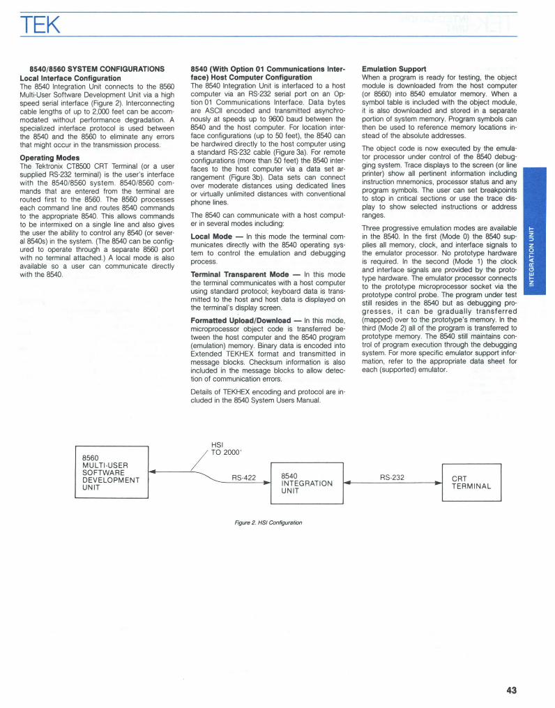
8540/8560 SYSTEM CONFIGURATIONSLocal Interface ConfigurationThe 8540 Integration Unit connects to the 8560Multi-User Software Development Unit via a highspeed seriai interface (Figure 2). Interconnectingcable lengths of up to 2,000 feet can be accommodated without performance degradation. Aspecialized interface protocol is used betweenthe 8540 and the 8560 to eliminate any errorsthat might occur in the transmission process.
Operating ModesThe Tektronix CT8500 CRT Terminal (or a usersupplied RS-232 terminal) is the user's interfacewith the 8540/8560 system. 8540/8560 commands that are entered from the terminal arerouted first to the 8560. The 8560 processeseach command line and routes 8540 commandsto the appropriate 8540. This allows commandsto be intermixed on a single line and also givesthe user the ability to control any 8540 (or several 8540s) in the system. (The 8540 can be configured to operate through a separate 8560 portwith no terminal attached.) A local mode is alsoavailable so a user can communicate directlywith the 8540.
8540 (With Option 01 Communications Interface) Host Computer ConfigurationThe 8540 Integration Unit is interfaced to a hostcomputer via an RS-232 seriai port on an Option 01 Communications Interface. Data by1esare ASCII encoded and transmitted asynchronously at speeds up to 9600 baud between the8540 and the host computer. For location interface configurations (up to 50 feet), the 8540 canbe hardwired direclly to the host computer usinga standard RS-232 cable (Figure 3a). For remoteconfigurations (more than 50 feet) the 8540 interfaces to the host computer via a data set arrangement (Figure 3b). Data sets can connectover moderate distances using dedicated linesor virtually unlimited distances with conventionalphone lines.
The 8540 can communicate with a host computer in several modes including:
Local Mode - ln this mode the terminal communicates directly with the 8540 operating system to control the emulation and debuggingprocess.
Terminal Transparent Mode - ln this modethe terminal communicates with a host computerusing standard protocol; keyboard data is transmitted to the host and host data is displayed onthe terminal's display screen.
FormaUed Upload/Download - ln this mode,microprocessor object code is transferred between the host computer and the 8540 program(emulation) memory. Binary data is encoded intoExtended TEKHEX format and transmitted inmessage blocks. Checksum information is alsoincluded in the message blocks to allow detection of communication errors.
Details of TEKHEX encoding and protocol are included in the 8540 System Users Manual.
Emulation SupportWhen a program is ready for testing, the objectmodule is downloaded from the host computer(or 8560) into 8540 emulator memory. When asymbol table is included with the object module,it is also downloaded and stored in a separateportion of system memory. Program symbols canthen be used to reference memory locations instead of the absolute addresses.
The object code is now executed by the emulator processor under control of the 8540 debugging system. Trace displays to the screen (or lineprinter) show ail pertinent information includinginstruction mnemonics, processor status and anyprogram symbols. The user can set breakpointsto stop in critical sections or use the trace display to show selected instructions or addressranges.
Three progressive emulation modes are availablein the 8540. In the first (Mode 0) the 8540 supplies ail memory, clock, and interface signais tothe emulator processor. No prototype hardwareis required. In the second (Mode 1) the clockand interface signais are provided by the prototype hardware. The emulator processor connectsto the prototype microprocessor socket via theprototype control probe. The program under teststill resides in the 8540 but as debugging progresses, it can be gradually transferred(mapped) over to the prototype's memory. In thethird (Mode 2) ail of the program is transferred toprototype memory. The 8540 still maintains control of program execution through the debuggingsystem. For more specifie emulator support information, refer to the appropriate data sheet foreach (supported) emulator.
SH 1
8560 / TO 2000'
MULTI-USERSOFTWARE
RS-422 8540 RS-232DEVELOPMENT CRTUNIT INTEGRATION TERMINAL
UNIT
FlfJure 2. HSI Configuration
43

TEK INTEGRATIONUNIT
DiagnosticsThe 8540 has a complete diagnostic subsystem.On each power-up cycle, diagnostic firmwarechecks the basic 8540 operation before leavingthe operating system. In addition, a complete diagnostic system is available for an extensive system verification (including ail options) and to perform board level fault isolation for quick on-siterepair.
Trigger Trace AnalyzerThe Trigger Trace Analyzer (TTA) , optionalequipment for the 8540, is a powerful debuggingtool. It monitors program flow in realtime and allows sophisticated control and analysis of theemulator processor. The TTA stores program information in a high-speed 255-event buffer. Eachevent contains 62-bits of information including:up to 24-bits of address and 16-bits of data; upto 14-bits of processor information, and 8-bits ofexternal probe information. TTA information isdisplayed on the terminal in processor specificmnemonics along with ail pertinent register andflag information.
PROM ProgrammerThe PROM Programmer, optional equipment forthe 8540 is a general purpose controller unit withplug-adaptor modules. Each module supports agroup of similar programmable devices. Functions include: Read, Write, and Compare.
CHARACTERISTICSOperating System (Software) - DOS/50 derivative (contained in 8 k PROM/ROM's) Le., 88 k bytes, command interpreter and kernel 24 k bytes diagnostics; 4 k bytes patch andcommand storage (EEPROM).Card Siot UsageStandard BoardsSystem controllerEmulator controllerSystem memory (64 k RAM)Pragram memory (32 k RAM)System memory (240 k PROM/ROM capacity)
Empty Board Slots -System side: 1 slotPragram side: 11 slots
1/0 Ports - J100 (8560 Interface); J101 (remote OTE male);J102 (rernate OCE lemale); J103 (Une Printer, Aux); J104(Terminal).
1/0 Port Data Rates - J100 (HSI) - 153.6 k baud.J101, J102, J103, J104 = 110/ext CLK, 150,300,600,1200,2400, 4800, 9600 baud.
ReliabilityMTBF - 6700 hour (calculated).MTIR Board - 0.5 hour.MTIR Component - 1.5 hour.
Standard Compliance - UL 1244; CSA Bulletin 556B;IEC 1348.
ENVIRONMENTAL CHARACTERISTICS
Temperature RangesOperating - O"C ta +50"C (+32"F ta +122"F).Storage - +55"C ta +75"C (+67"F ta +167"F).
Altitude RangeOperating - Sea Ievel ta 4500 m (15,000 ft).
Storage - Sea level ta 15 000 m (50,000 ft).
Humidity - 0 ta 90% noncondensing (O"C ta +50"C).
AC POWER
Nominal Operating Voltage - 115 V ac and 230 V ac at60 Hz.Power Requirements - 700 W maximum.Line Voltage Ranges - 90 ta 132 V ac and 180 ta 250 v ac.Llne Frequency Range - 48 ta 66 Hz.
PHYSICAL CHARACTERISTICS
Cabinet
Dimensions mm in
Width 430 17Height 280 11Depth 585 23
Weight kg lb
Net 26 57.5Shipping' 35 77.5
Cabinet Color - Three tone; ivory/gray, smol<e tan, earthbrown.
• Standard configuration on/y, no options.
RS-232 Communications InterfaceOption 01 - Interface signais are routed ta and Iram the 8540system controller board via rear panel connectors J101 (male)and J102 (Iemale). Table 1 lists the J101/Jl02 pin numbers andcorresponding signal names and descriptions. Baud rate ontransmitted data and received data is selectable Irom 110 ta9600 baud. Ali signais are RS-232C compatible.
Table 1Interface Signal (Option 01, Communications Interface)
SignalName Circuit J101DTE J102DCE Pin
GNO AA Protective ground Protective ground 1
Tx BA Out ln 2"
Rx BB ln Out 3"
RTS CA Out" In'3 4
CTS CB In-· Out" 5
OSR CC In-6 Out 6
GNC AB Signal ground Signal ground 7
OCO CF ln" Out 8
OTR CD Out In-8 20
., Selectable, /10 ta 9600 baud.'2 OTE 1, OTE 2 modes; goes high when data ta sand.'3 OCE mode; must be high before 8540 accepts data.., OTE 1 mode; must be high before 8540 sands data.., OCE mode; goes Iow when 8540 sends data.'0 OTE 2 mode; must be high before 8540 sends data." OTE l,OTE 2 mode; must be high before 8540 accepts data.'s OCE mode; must be high before 8540 sends data.
Order 8540 Integration Unit $11,000OPTIONAL ACCESSORIES
Flex Disks (box 01 10). Order 119-1182-01 5175RS-232 Connecting Cable (15 ft).
Order 012-0757-00 _ 5140HSI Connecting Cable (8 ft/2.4 ml.Order 012-1009-00 555HSI Connecting Cable (20 ft/6.1 ml.Order 012-1008-00 590HSI Connecting Cable (50 ft/15.2 ml.Order 012-1007-00 5125HSI Connecting Cable (250 ftl76.2 ml.Order 012-1010-00 5395
DIRECT/.RS-232
Ta 50'HOST
8540 RS-232COMPUTER OPT 1 CRTCOMM INTEGRATION TERMINALINTFC UNIT
Figure 3a. Direct RS-232 Configuration
DIAL UPOR
/ DEDICATED L1NES
RS-232
~RS-232
OPT 1 8540RS-232
HOST - DATA DATACOMM INTEGRATION
CRTCOMPUTER SET SET
INTFC UNITTERMINAL
Figure 3b. Data Set Configuration
44

TEK EMULATOR PROCESSOR ANDPROTOTYPE CONTROL PROBE SUPPORT PACKAGES
Emulator Processor and Prototype ControlProbe Support PackagesThe 8500 Microcomputer Development Lab family supports a wide variety of differentmicroprocessors and microcomputers.
EmulatorsEmulator packages may be ordered as systemsoptions. These options provide capabilities necessary to fully emulate the target microprocessorin a user's prototype system.
The emulator processor, which resides on aplug-in circuit module along with controlling logiccircuitry, enables the user to execute and debugthe program on a microprocessor identical to theone which will be used in the prototype, whilegiving him access up to 256 kilobytes ofMicroprocessor Lab program memory.
Software execution is pertormed under control ofDOS-50 in the 8550 system, and under control ofTNIX in the 8560 system. During software development, DOS-50 allows the creation of a tree-likefile structure with subdirectories to whatevernesting level a project requires. When convertingsource code to object code, it provides complete supervision of assembly or compilation procedures. During hardware/software integration,DOS-50 handles prototype execution monitoringand debugging operations. It also takes care ofgeneral 1/0, intersystem communications andPROM programming.
TNIX, the operating system used in the 8560 system uses timesharing to apportion system resources among up to eight work stations plussystem utilities. A hierarchial-type filing system isused that groups files and directories logically.Each file carries a date/time attribute to helpconfirm that the proper version is beingaccessed. A security system allows passwordprotection, multiple-user file access, and workcopies according to current project needs.
ProbesThe prototype control probe connects the emulator processor card to the prototypemicroprocessor, and allows a designer to transfer program control in three stages from the8550 or 8560/8540 Microcomputer DevelopmentLab to the prototype.
Ali emulation operations are controlled by thepowertul Microprocessor Lab system software.The user is able to monitor program execution,set software breakpoints, examine and changememory and register contents. Debug trace information is displayed in a format unique to themicroprocessor, with instruction fetches disassembled into mnemonics for easy interpretation.
Three Emulation ModesOnce an object code file has been created, theprogram may be exercised in system Mode O.During execution, program steps can be traced,hardware breakpoints can be set, and memorycan be examined and changed as required.Should an error be discovered, that portion ofthe program can be corrected at the source level using the text editor. Object code can then bereassembled and re-executed. This procedurecontinues until the developmental software program is complete and can be executed withouterrors.
After the developmental software has been debugged, it may be exercised on the prototypecircuitry (Mode 1). During partial emulation, control may be released in stages to the prototype.Developmental software is sequenced using theemulator memory space and the prototype 1/0and clock. The memory mapping feature allowscode to be gradually mapped over to the prototype's memory in blacks. Throughout partial emulation, the program designer has access to prototype circuitry. This access enables theexamination and changing of memory and register contents, hardware tracing, and setting ofbreakpoints.
ln full emulation, Mode 2, the developmental software program is run on the prototype, but program execution is still under the complete control of the 8550 Microcomputer Development Labor 8540 system. Ali 1/0 and timing functions aredirected by the prototype and ail memory hasbeen mapped over to it. The Prototype ControlProbe is connected and still emulating the prototype microprocessor. Although the prototype iseffectively free-standing, the designer may stilldirect program activity from the console terminal.
PROM ProgrammerAn optional PROM programmer is available foruse with the 8550 MDL and the 8540 IntegrationUnit.
The PROM programmer includes the general purpose controller board and a series of front panelplug-in modules. Each plug-in module providessupport for a similar group of PROM devices,and can be changed in a few seconds. Programming features include reading, writing, and comparing (for verification) a PROMo
ORDERING INFORMATIONProm Program $2000Option 30 Controller $2000
PROM MODULE DEVICE MANUFACTURER
Option 31 TMS 2508 TI2758 Intel275851865 IntelTMS 2516 Intel2816 IntelTMS 2532 TI2732 Intel2732A IntelMCM 68764 MotorolaMCM 68766L35 Motorola
Option 32 8755A Intel8748 Intel8749 Intel8741 A Intel
Option 33 2764 Intel27128 Intel2817 IntelTMS 2564 TI
Option 35 8751A Intel
45

TEK TRIGGER TRACE ANALYZEREMULATION SYSTEMS
TRIGGER TRACE ANALYZERThe TTAThe Trigger Trace Analyzer, or nA, is the fundamental debug and integration tool in the 8500family. This two-board package works with emulators inside the 8550 or 8540 mainframe to providethe user with unprecedented control over software execution. The nA is a universal tool,supporting most of the 8-bit and 16-bit emulatorsin the 8500 family.
Interactive Control of Software ExecutionThe nA opens a kit of powerful tools for theuser. Conventional breakpoint and trace functionsare just the beginning. The programmer can trapread, write, or execute accesses to any part ofmemory, break when a subprogram has beencalled in a particular sequence, and track registercontents while uninvolved instructions execute atfull speed.The bus cycle recording capabilities of the nApermit tracing of instructions while themicroprocessor runs at full speed. Trace qualification hardware gives the user the power tospecify what cycles should be recorded, so anentire program execution can be recorded, forinstance, as a list of cali instructions.ln addition, the nA's performance analysis capabilities can identify code "hot spots", recognizeunused sections of code, measure the time nec-
46
essary to traverse a routine, or even dynamicallymonitor the growth of a list or a stack.Ali of these capabilities, of course, use Tektronix'symbolic debug system, so that the programmermay work with source code symbols and neednever grope through linker listings trying to findhex addresses or misplaced subprograms.
Complete TransparencyThe nA provides ail these capabilities withoutmaking demands on the prototype. No waitstates are inserted by the nA, no code is placedin the user's memory space, and no specialhardware provisions are required. Like Tektronixemulators, the nA is completely transparent tothe customer's design.When working with 16-bit chips that feature multiple address spaces, the nA distinguishes between the spaces. This means, for instance, thatthe Motorola 68000 programmer can set a hardware breakpoint at location 5000 in User Programspace without causing a break at location 5000 inSystem Program space.
A Network of Integration TooisBy using its four trigger outputs and ninepattern/qualifier inputs, the nA can work in anetwork with other digital measurement tools,such as the DAS 9100 family, and with conventional or digital oscilloscopes. This ability to sendand receive trigger information makes the nA
the center of a network of integration tools,permitting microprocessor, peripheral, and outside analog measurements from a variety ofinstruments to be correlated.Only this' level of integration support makes itpractical to debug the complex systems of processors, peripheral chips, and analog equipmentthat occur so often in modern designs.
How the TTA WorksThe nA consists of two major subsystems. Onesubsystem is responsible for recognizing events,and the other for making real time recordings ofprogram activity.The event recognizing subsystem is a group ofprecise tools. There are four independent triggerchannels. Each channel can recognize addresses, address ranges, or address windows (functions normally requiring two separate triggers) asweil as data, control signais, and state information from the other channels. Each channel alsohas a flexible, programmable counter that can beused for counting, timing, or linking the events asthey are detected. The channels may be linked inand, or, or sequence configurations to meetnearly any triggering need.Real time recording is provided by a 255 word by62 channel high-speed recording butter. Therecord may be frozen by an event channel, sothat a sequence of instructions can be recordedat full prototype speed, and then held for examination after the prototype has reached a safestopping place. In addition, the butter can be setto record only on command from one of the eventchannels, permitting a long prototype run to becondensed to a trace of the crucial events.Working together, the tools in the nA providedebug and integration capabilities never availablein one system before the introduction of the 8500family.
TEKTRONIX EMULATION SYSTEMSWhat is Tektronix Emulation, Exactly?Not surprisingly, every manufacturer tries to define emulation in terms of the capabilities andlimitations of their own product. Unfortunately,this has led to some rather distorted views ofwhat emulation is, and what it is for.Tektronix has a simple, comprehensive view ofemulation. Emulation is the technique of controlling the microprocessors in a device so thatsoftware execution may be observed and controlled. Emulation is accomplished by placingeach microprocessor in a probe assembly, whereit can be controlled by the development systemwithout compromising the chip timingcharacteristics.A Tektronix, we believe that emulation should bereal time, transparent, and full-function. Real timemeans that the device under control runs at itsintended clock speed with no wait states insertedby the development system. Transparent meansthat the device under control runs exactly thesame way with the emulator as with themicroprocessor itself. No added circuits, no"monitor" software, no compromises in chip timing at critical pins. FulHunction means that ail thefeatures of the microprocessor, including interrupts, multiprocessing features, co-processing,and address space separation, are supported bythe emulator.

TEK
Ftgure 2. TTA Acquisilion Control
Table 2 TTA Command SetCommand Description
acq Acquire Data: Controls data storage in the high-speed trace buffer; allows event fourparameters to act as a storaqe qualifier when specified.
ad Address Comparator: Programs address portion of each channel's word recognizer.
bre Breakpoint Control: Halls nA data acquisition when a specified channel's triggeroutput goes active; includes option to let prototype continue executing code.
bus Bus/Control Signais Comparator: Programs control bus portion of each channel's wordrecognizer; specific control signal mnemonics supplied with each emulator package.
cons Detect Consecutive Cycles: Specifies sequence in which trigger channel events mustcome true to cause a data acquistion triqqer; selects type of bus cycle to be used.
cou Counter Programming: Determines counter value that will cause active counter output;includes increment/decrement select countina source select and reset function.
ctr Counter Output Feedback: Programs counter output feedback portion of each channel'sword recognizer.
data Data Comparator: Proqrams data portion of each channel's word recoqnizer.
disp Display Acquisition Memory: Displays acquired bus activity in disassembled mnemonicsnative to the emulator processor in use.
eve Event Comparators: Single command allowing ail of a channel's word recognizer valuesto be programmed at once.
pro External Probe Input Compartor: Programs probe input portion of each channel's wordrecognizer (8 bits).
qua External Qualifier Comparator: Programs external qualifier portion of each channel'sword recoqnizer (sinqle bit received via BNC input).
tclr Clear an entire trigger channel (event, counter and breakpoint).
ts Trigger Status Display: Shows ail trigger information current programmed on each of thefour trigger channels including breakpoint status.
1---. To DisplayProcessing
opment system resources to substitute for partsof a prototype system that are not available fortesting. As an example, the winchester disk in the8560 can be accessed from a prototype tosimulate a prototype mass storage system stillunder development.
The SystemsThe Tektronix 8500 family providesmicroprocessor emulation in three formats for thethree different kinds of design teams. In the 8550,emulators share a cabinet with software development facilities. This provides the most cost-effective packaging for teams in which several usersdo not need to work simullaneously.
ln the mulli-user 8560 environment, where severalmembers of the team must be able to use thedevelopment system at once, emulation is provided in a separate cabinet, the 8540. This permitsTektronix emulators to be operated from anystation in the system without tying up softwaredevelopment facilities.
For design teams that use mainframe computersfor software development, the 8540 connectsdirectly to the host computer to provide Tektronixemulation as a natural augmentation of the existing computer facilities.
Emulation AccessoriesSeveral accessories expand the emulation capabilities of the 8550 and 8540 systems. Additionalprogram memory is available in 32, 64, or 128kilobyte increments to accommodate large software modules. For two of the 16-bit emulators,the 68000 and zaooo, a separate memory control1er permits the program memory to replaceblocks of prototype memory over the chips' entireaddress ranges, in any of the chips' addressspaces. This mapping feature makes it unnecessary to reassemble or relink code to fit it into aparticular address range during debug.
Two logic analyzers, an economical Real timePrototype Analyzer for 8-bit microprocessors andthe unprecedented Trigger Trace Analyzer formost 8 and 16-bit processors, extend the debugfeatures of the 8500 family to meet the challenges of the most formidable software projects.
The System SolutionA wide variety of emulators, mainframes to fit theneeds of design teams, memory and analysisoptions together with the 8500 family emulationproducts, form a system that is cost effective foran individual project and flexible enough not to beoutgrown.
Address -----\ 24
Data -----\ 16 255 x 62MEMORY
Probe 8
Processor 141 STORE 1Dependent --'
Event 4Qualification
velopment, Tektronix Prototype Control Probesextend the capabilities of emulators into thedevice.
Prototype Control ProbesThe Prototype Control Probe is the connectionbetween a Tektronix emulator and the deviceunder test. The probe replaces the user'smicroprocessor, extending ail the emulator's debug capabilities to the device under test.
Via these probes, Tektronix emulators can execute code from the device under test, examine orchange the device's memory contents, set breakpoints, trace program execution, and map portions of development system memory into thedevice's address space. Further, Tektronix 16-bitprobes permit Service Calls to be performed fromthe device under test. This feature permits devel-
Address 24
Data 16 EventOutput
Probe 8 COMPARATOR
Micro ---\ 11Dependent
Counter 4
TriggerExternal OutputQualifier
Clock 17 16-61TSources COUNTER
Figure 1. TTA Channel Configuralion
Tektronix EmulatorsTektronix offers emulators for most major 8-bitmicroprocessors and microcomputers. We setthe standard for 16-bit emulation of the 8086,8088,68000, Z8001, Z8002, and 9900.
Each Tektronix emulator can execute code fromprogram memory in the development system.Each provides hardware breakpoints, single-step,and trace capabilities. Each emulator can performService Cals (SVC's) which make the hardwareresources and software tools of the developmentsystem available to user programs.
With these facilities Tektronix emulators provide acomplete enviroment for software debug insidethe development system. When the time comesto test software operation in the device under de-
47

TEK SOFTWARETOOLS
Memory Allocation allows program memory to be assigned todifferent Iogical addresses within the microprocessor addressrange.
The Memory Allocation ControllerThe Memory Allocation Controller is an option tobe used with the 68000 and Z8000 support packages. It allows full support of these processors'address ranges, as weil as support of the six address spaces of the Z8000 and the four addressspaces of the 68000. Memory is allocated in 4 kblocks over the entire address range, and cana/so be allocated as existent and nonexistent, inwhich case any read or write to nondefinedmemory will be flagged as an error condition.
The 8086 emulator supports the full 1 megabyteaddress range without this option.
LANDS Pacal CompilerPascal, high-Ievel programming language, is receiving much attention in the electronics industry. Features, such as program structure, strongdata typing, and readability, greatly enhance programmer efficiency, and thereby reduce software development and maintenance costs.
The Tektronix Pascal Compiler implements theproposed ISO Standard Pascal, withmicroprocessor application extensions. A truecompiler rather than a P-code interpreter, thePascal Compiler generates object code for thetargeted chip directly. Each program statementis translated to machine code only once insteadof every time the statement is executed, resulting in faster and often more compact code.LANDS Pascal on the 8560 is currently targetedfor the 8086/8088 and Z8001/Z8002 chips.
Standard Pascal FeaturePascal is a block-structured language that allowsthe program to be divided into subprogramscalled procedures and functions. This blockstructure encourages programmers to logicallyplan and construct programs, so debugging timeis greatly reduced.
Pascal's control structures correspond closelywith flowchart elements and make algorithmcoding very natural. Ali control structures have asingle entrance and exit, so program modifications are unlikely to introduce errors into theprogram.
Pascal allows programmers to use many flexibleforms of data representations and to define datatypes that accurately express their particularproblems. Tektronix Pascal allows ail standarddata types: integer, real, character, Boolean,enumerated, set, array, record, file, and pointer.
Pascal programs are easy to read, and thus tomaintain. Pascal allows extra spaces, tabs, andcarriage returns almost anywhere, so indentedspaces can be added to make the programmore readable. Variable, procedure, and functionnames can be meaningful and easily understoodbecause they are not restricted in length.
Tektronix Pascal ExtensionsExtensions have been added to the standardPascal to assist in microprocessor applications.
Separate CompilationsThe Tektronix Pascal Compilers support separatecompilations. The main program module's firstword is the keyword Program. Submodules to beseparately compiled begin with the keywordModule.
Global variables, procedures, and functions canbe referenced between separately compiledModules and the main Program via Public andExtern attributes.
Linkage with Assembly Language ModulesSpeed-critical or timing-critical applications mayrequire some program segments to be written inassembly language. Because the code generated by the Pascal Compiler is compatible with theTektronix-Linker, assembly code can be linked toPascal code.
LANDSThe Tektronix Pascal Language DevelopmentSystem, optional software for the 8560, providesan integrated set of language developmenttools. The Language-Directed Editor (LDE), thePascal Compiler with an Integration Control System (ICS), and Pascal Debug (PDB) are toolsthat support your design effort, from code entrythrough debugging.
Language-Directed EditorThe Language-Directed Editor (LDE) for Pascal,eases editing of programs written in the Pascallanguage. The LDE combines text manipulationfunctions of a general purpose editor with thesyntax-checking function of a compiler.
LDE is tailored to the syntactic structure of thePascal language, allowing more productiveediting of Pascal programs than a general purpose editor. The Parse command checks thesyntactic validity of the text entered, saving yourepeated compiler passes for syntax checking.
The LDE provides an auto-indentation at the timeof text entry by remembering the level of indentation of the previous line. Language-DirectedEditing provides a generic key to facilitate entering Pascal's reserved words. When the generickey is entered during the typing of a Pascal reserved word, the LDE completes the text entryof that word, reducing spelling errors and typingeffort. For example, if you type "PROC' or "PR'and then enter the generic key, the work "Procedure' is entered into the text.
As a screen-oriented process, LDE displays ascreenful of text in your file, allowing you to viewthe text surrounding the point of editing that isindicated by the cursor. The terminal screenserves as a window into the file where you caninsert or modify text. The text is automaticallyscrolled up or down through the display windowas the cursor is moved with the cursor movement keys. New text can be entered at the position of the cursor by simply typing in characters.LDE commands, implemented by programmedkeys on the keyboard are available to modify ordelete text.
SOFTWARE TOOLSTektronix offers a variety of software tools forthe microprocessor design development cycle,including:- A Language Development System, LANDS,on the 8560, which provides an integrated set oftools from code entry through debugging.- Editors for Data Entry: A screen (CRT)-oriented editor, in addition to the standard line-oriented editor.- High-Ievel-Ianguage compilers, Pascal andMDUIt specifically designed for microprocessorapplications.- Assemblers support for a wide range ofmicroprocessors to translate assembly languageprograms into relocatable object modules.- A powerful linker to merge the object modules and a library generator to create and maintain object module libraries are standard with theoperating system.
MicroprocessorMemory Address
Spsce
8550/8540ProgramMemory
48
TEK
Interrupt HandlingTektronix Pascal allows full use of the microprocessor interrupts. You can specify the procedureto be executed for an interrupt routine with theInterrupt altribute in the procedure heading.
Input/OutputTektronix Pascal allows full use of the Chip 1/0.The Port and Origin allributes can be used to 10cate a variable at a given 1/0 port or memorylocation.
Nondecimal Integersln many microcomputer applications, programmers want to use nondecimal integers. The Pascal Compiler supports binary, octal, and hexadecimal integers for input and output.
Bit ManipulationTo allow bit manipulation and masking, Booleanoperators can be used with integers in theTektronix Pascal.
Compiler DirectivesTektronix Pascal recognizes a set of compilerdirectives to format the listings, include externalfiles, and generate a pseudo-assembly languagelisting of the object code produced by thecompiler.
Integration Control SystemIncluded with the LANDS Pascal is a softwareprogram, known as the Integration Control System (ICS), that simplifies the integration of yourPascal program to your particular hardware configuration. With Pascal, there is no direct way tospecify implementation-specifie requirementssuch as interrupt vectors, restart routines, ormemory configuration. The ICS allows the programmer to specify such configurations and create the necessary assembly language routinesand linker commands automatically.
ICS allows the user to configure the program torun on his prototype after the source program iscompiled and checked. Changes in the hardware configuration do not require recompilingthe source programs.
Pascal DebugThe Tektronix Pascal Oebug is a real-lime symbolic debugging tool for programs that are written in Pascal. Pascal Oebug (POB) allows theprogrammer to use Pascal language constructsto examine and modify the program duringexecution.
With POB, the programmer can debug his program without a detailed knowledge about thecompiler-generated code, thus, extending the efficiency of coding in a high-Ievel-language to thedebugging cycle.
Pascal Oebug, which runs on the 8560 Multi-UserSoftware Oevelopment Unit, controls the program as it executes at full speed on the targetedemulator in the 8540 Integration Unit. Usable inany emulation mode, POB generates 8540 commands to run the emulator. Any 8540 error messages returned are examined and, in somecases, repaired allowing the debugging sessionto proceed.
Displaying/Modifying VariablesPOB provides the programmer with a high-Ievellanguage interface to display and modifyvariables.
Variable modification commands in POB areused to examine and change the values of variables. POB allows the programmer to refer to thevariables using the same symbolic names declared in the original source code.
POB recognizes the same types of expressionsas the Pascal compiler. General expressions areaccepted as arguments for POB commands.
HIGH LEVELLANGUAGE
Controlling Program ExecutionPOB allows the programmer to control the execution of the program flow with breakpoints, single-steps of Pascal statements, returns to callingprocedures, and program resets.
Recording and Displaying DebugInformationPOB has several commands to record and display important debugging information, includingthe trace command to trace previous calls; TB(traceback) command to interpret the activationrecord list, in reverse order, the procedurescalled, displaying a traceback to the main program; and a Log command that records ail POBinput and output to a file, so it can be reviewedand analyzed later.
EDITORSln addition to the Language-Oirected Editor onthe 8560 and the standard line-oriented editors,Tektronix offers ACE, an Advanced CRT-Oriented Editor. Optional software to both the 8550and 8560, ACE eases program creation andediting tasks.
With the ACE Editor, programmers may conveniently view and edit the program text. A window, the CRT, shows the text surrounding theACE Editor's pointer. The text can be edited either as a sequence of lines or a stream ofcharacters.
Sereen Oriented EditingACE divides the display screen of the CRT intotwo areas: a monitor area to display messages,and a window area to display text that is beingedited. The window constantly shows the textsurrounding the cursor, a visible pointer in thewindow area of the screen. The cursor is movedby the user to the specifie character within thetext where editing will occur. Text displayed inthe window can be moved both horizontally andvertically to bring different parts of the file intoview. After an edit command has been processed, the window will display the change(s)made to the text.
PROGRAM MEMORY
49

TEK HIGH LEVELLANGUAGE
LANGUAGE DEVELOPMENT SYSTEM (LANDS)
LanguageDirectedEditor
PascalCompiler
\ Integration ~ControlSystem
PascalDebug
~:i:i:i:i:i:ii~i~@~iiiit~
~++
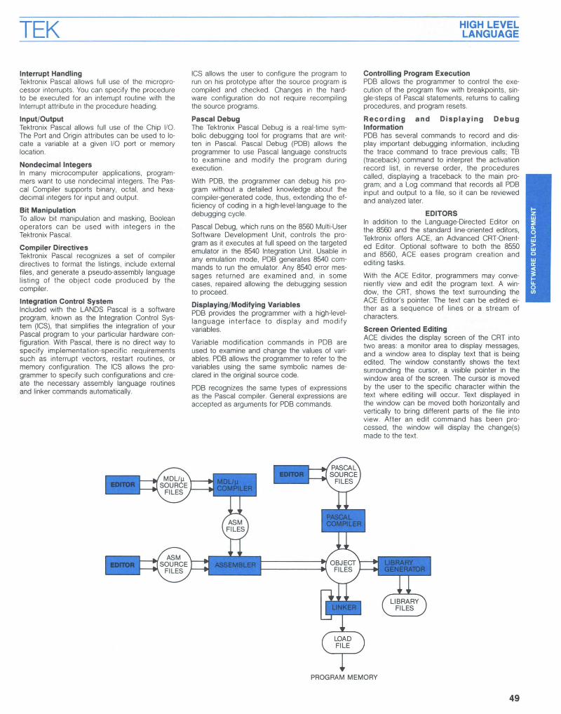
Pascal Language Development System (LANDS) -Together. the Language-Directed Editor, Pascal Compiler, Integration Control System and Pascal Debug provide the mast effi
cient and productive environment for high-levellanguage programming in microprocessor design.
Character and Une ManipulationIt is often desired to edit text at one place as asequence of lines and at another place as astream of characters. ACE is versatile, permittingboth character and line manipulation. Charactermanipulation features allow the user to find, orfind and replace, multiple occurrences of a character string, to insert or delete characters. Othercharacter manipulation capabilities such asovertyping, copying from one position to another,and changing alphabetic character case canalso be accomplished. Line manipulation features include insert and delete lines, move lines,split one line into Iwo, and combine two lines intoone. The operator can, at any time, use line-oriented commands.
During execution of ACE, the user may define,view and invoke macros. The use of macros allows the user to define a sequence of ACE commands that may be called many times during anediting session.
Terminal SelectionThe advanced CRT-oriented Editor is configuredto operate with the Tektronix CT8S00 Terminal.For optimum performance and software supportunder the license agreement, Tektronix recommends the CT8S00. ACE, however, may be configured to operate with alternate CRT terminais.Depending on the terminal functions, some degradation may occur. While ACE is designed towork with terminais of varying characteristics,Tektronix does not warrant or support ACE withterminais other than the CT8S00.
The advanced CRT-oriented Editor requires64 kilobytes of program memory for correct operation. At no lime does the size of the workspaceaffect the size of the file that can be edited.
COMPILERSPascal Compilersln addition to the LANDS Pascal on the 8560,Tektronix offers Pascal compilers for theSOS6/S0SS and SOSO/SOS5 microprocessors onthe 8550 Microcomputer Development Lab.
Both Pascals implement the proposed ISO Standard Pascal and are developed formicroprocessors designed with the TEK Pascalextensions. The 8086/8088 Pascal includes theIntegration Control System.
MOLlit CompilersAn expanded form of ANSI Minimal Basic, theMOllit Compiler is a high-Ievel language designed specifically for microprocessor-basedproduct development. A system option availablewith the 8550 MDL, MOllit supports softwaredevelopment of the 808OA, the 8085A and theSOSOA subset of the ZSO microprocessors. Asecond system option supports software development of the 6S00, 6S02, and 6S0Smicroprocessors.
Like Minimal Basic, MOllit is easy to learn anduse. Offering additional advantages such as increased flexibility in variable name and stringdefinition, direct access to 1/0 ports and absolute memory addresses, MOllit also provides enhanced function, statement and operatorcapabilities.
The MOllit compiler produces executable, notinterpreted assembly language code. Each program statement is compiled into machine codeonly once, instead of every time the statement isexecuted. Thus, fewer operations result in fasterand often more compact code for final programexecution.
MOllit makes possible a module-oriented approach to software development. The programmer may create user-defined libraries of assembly language code or may use routines from theMOllit support routine library. These callableroutines are stored on flexible disks in objectcode and are brought into the main program atlink time. Ali support routines except those relating to 1/0 activities are serially re-entrant; that isthey use no temporary values other than those inthe registers and on the stack. Register contentsare saved when an interrupt occurs and restoredwhen the interrupt is completed.
An additional feature of the MOllit compiler isthat two statements, Uses and Provides, allowvariables, functions and procedures to be sharedby different modules of the main program.
Teklronix o"ers service treining clesses on MlcroprocessorDevelopmenl Lebs. For lurther Irelnlng Inlormellon, conleclyour locel Seles/Servlce Office or requesl e copy 01 IheTeklronlx Service Trelnlng 5thedule on the retum cerd inIhe cenler 01 Ihis celelOll.
50
TEK
Assemblers SupportTektronix Assemblers support software development for a wide range of microprocessors, thusallowing you the flexibility to choose themicroprocessor best suited to your particular application. Each assembler also maintains identical operational characteristics for eachmicroprocessor supported, greatly facilitatingyour ability to move from one microprocessor toanother.
The assembler, which recognizes the instructionset, registers addressing modes, and full address space of the specific microprocessor, thentranslates assembly language statements intomachine instructions (object code) for thatmicroprocessor. However, the programmer mayuse the same assembler directives and advanced programming features, such as time-saving macros and language extensions, with everyassembler.
Powerful macro capability enables theprogammer to write a segment of source codeonly once, and cali it up for in-line code expansion as often as required. Additionally, parameters can be passed to the macro, allowing a different sequence of code for each invocation.
Conditional assembly directives allow a sequence of source code statements to produceobject code that varies according to conditions.For example, a statement or statements insidean IF block will be assembled if the operand expression with the IF directive is true. This featureserves to reinforce the macro capability, allowingthe designer to customize the final program.
Other language extensions allow operand expressions to contain bit and string manipulationsas weil as standard arithmetric operations. Dataconstants may be entered as binary, octal, decimal, hexadecimal, or ASCII characters.
8550 Assembler Support: 8080A, 8085A, Z80,6800, 6801, 6802, 9900, 9989, 3870, 3972, F8,1802, 8048 Family, 8051, 6500/1, 6809, 8086,8088,68000, Z8001, and Z8002.
8560 Assembler Support: 8080A, 8085A, zao,6800,6801, 6802, 1802,8048 Family, 8051, 6809,9900, 9989, 8086, 8088, 68000, Z8001, andZ8002.
LinkerThe Linker merges one or more object modulesinto a load file that is suitable to load into thedevelopment system's program memory. Theload file contains executable program instructions and data. The Linker assigns exclusive address ranges that each program section willoccupy.
Any of the following attributes may be defined atlink time: relocation type of a section, exact orapproximate location of a section, global symbolvalues, and address of the first instruction to beexecuted. The programmer may specify simplelinking operations with a single command line.Special or complex operations can be specifiedwith a series of Linker commands from a command file.
The user can list the location of ail global symbols and sections, section length, unresolved references, undefined symbols, and the transferaddress.
Library GeneratorThe Library Generator is used to create andmaintain object module Iibraries. Subroutinescommonly used by one or more object modulesmay be stored in a library file. These subroutinesare developed and assembled separately andthe resulting object modules stored together inthe library.
The Library Generator allows you to insert. delete, or replace object modules in the library. Anyobject module contained in a library can be individually accessed by the Linker. At Iink time, theLinker will insert in the load file the object module of any routine that your source program calls.The user can list defined and undefined globalsymbols in each module of the library.
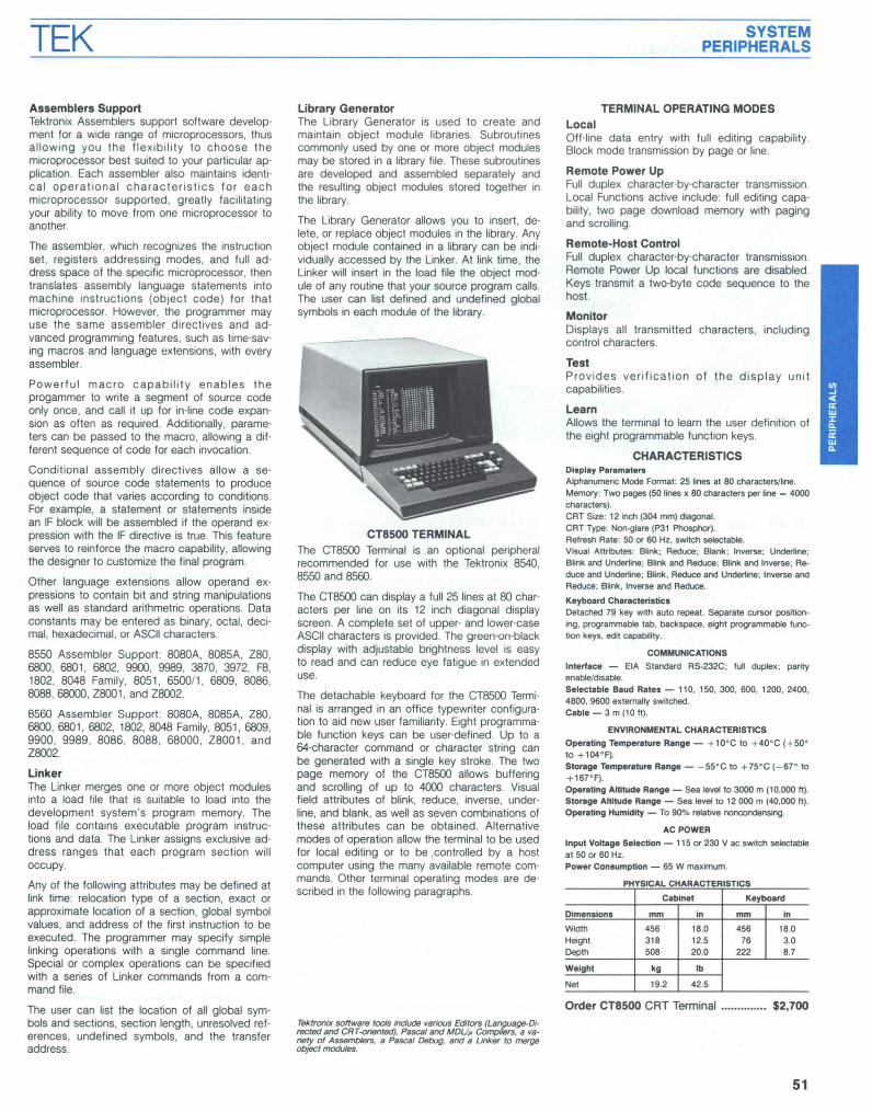
CT8500 TERMINALThe CT8500 Terminal is an optional peripheralrecommended for use with the Tektronix 8540,8550 and 8560.
The CT8500 can display a full 25 lines at 80 characters per line on its 12 inch diagonal displayscreen. A complete set of upper- and lower-caseASCII characters is provided. The green-on-blackdisplay with adjustable brightness level is easyto read and can reduce eye fatigue in extendeduse.
The detachable keyboard for the CT8500 Terminai is arranged in an office typewriter configuration to aid new user familiarity. Eight programmable function keys can be user-defined. Up to a64-character command or character string canbe generated with a single key stroke. The Iwopage memory of the CT8500 allows bufferingand scrolling of up to 4000 characters. Visualfield attributes of blink, reduce, inverse, underline, and blank, as weil as seven combinations ofthese attributes can be obtained. Alternativemodes of operation allow the terminal to be usedfor local editing or to be ,controlled by a hostcomputer using the many available remote commands. Other terminal operating modes are described in the following paragraphs.
Telctronix software tools include various Editors (Language-Directad and CRT-orientad), Pascal and MDUp Compilers, a variety of Assemblers, a Pascal Debug, and a Unker to mergeabject modules.
SYSTEMPERIPHERALS
TERMINAL OPERATING MODESLocalOff-Iine data entry with full editing capability.Block mode transmission by page or line.
Remote Power UpFull duplex character-by-character transmission.Local Functions active include: full editing capability, two page download memory with pagingand scrolling.
Remote-Host ControlFull duplex character-by-character transmission.Remote Power Up local functions are disabled.Keys transmit a Iwo-byte code sequence to thehosto
MonitorDisplays ail transmitted characters, includingcontrol characters.
TestProvides verification of the display unitcapabilities.
LearnAllows the terminal to learn the user definition ofthe eight programmable function keys.
CHARACTERISTICSDi.play Parameter.Alphanumeric Mode Format: 25 lines at 80 characters/line.Memory: Two pages (50 lines x 80 characlers per line - 4000characlers).CRT Size: 12 inch (304 mm) diagonal.CRT Type: Non-glare (P31 POOspller).Retresh RaIe: 50 or 60 Hz, switch selectable.Visual Attributes: Blink; Reduce; Blank; Inverse; Under1ine;Blink and Under1ine; Brink and Reduce; Blink and Inverse; Reduce and Underline; Blink, Reduce and Underline; Inverse andReduce; Blink, Inverse and Reduce.
Keyboard CharacteristicsDetached 79 key wilh auto repeat. Separate cursor posilioning, programmable lab, backspace, eight programmable funetion keys, edit capability.
COMMUNICATIONS
Intarface - ElA Slandard RS-232C; full duplex; parityenable/disable.Selectable Baud Rates - 110, ISO, 300, 600, 1200, 2400,4800, 9600 externally switched.Cable - 3 m (10 ft).
ENVIRONMENTAL CHARACTERISTICS
Operating Temperature Range - +10·C 10 +40·C (+50·10 +104·F).Storage Temperature Range - -55·C to +75·C (-67" 10
+ 167·F).Operating Altitude Range - Sea Ievel to 3000 m (10,000 ft).Storage Altitude Range - Sea Ievel 10 12 000 m (40,000 ft).Operating Humidity - To 90% relative nonoondensing.
AC POWER
Input Voltage Selection - 115 or 230 V ac switch selectableat 50 or 60 Hz.Power Consumption - 65 W maximum.
PHYSICAL CHARACTERISTfCS
Cabinet Keyboard
Dimensions mm in mm in
Width 456 18.0 456 18.0Height 318 12.5 76 3.0Depth 508 20.0 222 8.7
Weight kg lb
Nel 19.2 42.5
Order CT8500 CRT Terminal $2,700
51

TEK SYSTEMPERIPHERALS
4643 Printer
The Tektronix 4643 Printer provides fast, highquality, impact printing that is suitable for mostdata processing applications. With high reliabilitybuilt in, the 4643 is a convenient and economicalchoice requiring no preventive maintenance andinfrequent servicing.
The 4643 is a fast and highly reliable seriai printer for use with the 8500 Series development systems. The 4643 can be connected to either the8540, 8550 or 8560 to provide high quality hardcopy at a modest cost. The 4643 connects viaan RS-232 interface, so no special interfacecards or mainframe options are required foroperation.
Long, reliable service can be expected from the14-wire matrix head component. The 4643 backsup the printing of each character with more headwires to assure an expected (head) life of morethan 300 million characters with no maintenanceexcept normal cleaning. This figure normallymeans at least two full years of continuous workfrom a single matrix head. The fabric ribbonscontinuous loop cassette is usable for at least5 million characters. Both the matrix head andribbon cassette are quickly operator-replaceable,eliminating the need for a service cali.
High quality matrix printing is ensured by theunique 14-wire printing head. the 7 x 7 formatprint font permits easy reading and the operatorcan specify condensed, expanded or standardcharacters. In the condensed (character) facethe 4643 prints out a 132-character line format onan 8 '12 x 11 in sheet.
Because the 4643 uses impact printing, six verylegible copies (including five NCR or carboncopies) can be made to save time and avoid theexpense of photo copies.
52
You can generate output simply with the easy-touse 4643 Printer. The few operator controisneeded are conveniently ciustered at the front ofthe machine.
No attendance is necessary when the 4643 isrunning because the paper supply sensor automatically lets the machine print to the end of thelast form. With either front, back or bottom loading ports, loading the machine is also an easytask. The operator may quickly position the paper to be loaded with the help of built-in horizontal and vertical alignment guides.
CompatibilityThe printer of choice for high technology systems, the standard Tektronix 4643 is RS-232compatible and can be interfaced with moststandard RS-232 data processing instrumentsand systems. Option 01 provides a parallel interface. The 4643 is compatible with the followingTektronix products: 4010 and 4110 Series Terminais, 4020 Series Terminais, and 4050 SeriesDesktop Graphic Computing Systems; the 8001,8002A, 8540, 8550 and 8560 MicroprocesosrLabs; the S-3250, S-3270 and S-3280 Semiconductor Test Systems; the 7612D and 7912ADProgrammable Digitizers.
Fast But Not ExpensiveThe 4643 Printer uses bi-directional logic technology to print 340 characters/second. With a full132 character line, speeds of 125 lines/minuteare nominal. Even faster throughput rates areused for printing graphs and tables. The 4643Printer rivais the speed of many line printers butis available for the modest price of a matrixprinter.
Practical for Many ApplicationsThis versatile printer can be used, for example,as a fast way to record the stages-in-process ofsoftware program development. It can also pro-
vide the hard copy needed to analyze researchand development data. Because the 4643 outputis of report quality, you need only to push a button to generate reports on your research, programming or statistics directly from your database. For added convenience, you will find the4643 very useful in time consuming tasks suchas label generation, previewing text and correcting the format of manuals or letters prior totypesetting.
Virtually no maintenance means an even greatersavings, and less downtime for repairs as weil. Adiagnostic display and self-testing routine virtualIy eliminate the need for preventive maintenancecalls. On the infrequent occasion that somethinggoes wrong, you will find out directly from themachine.
Both the matrix head and ribbon cassette arequickly operator-replaceable, eliminating theneed for a service calI.
CHARACTERISTICSPrinling Speed - 340 characlers/second.Characler Oen.ityGondensed - 219 characterslline.Slandard - 132 characterslline.Expanded - 72 characters/line.
Throughpul RaIe132 CoIumns Wide - 125 Iines/minute.72 CoIumns Wide - 200 lines/minute.40 Columns Wide - 300 lines/minute.
Paper Siew RaIe - 254 mm/s minimum (10 inls minimum).
Characler Sel- 128 (96 ASCII plus 32 commonly used international characters).
Vertical (Une) Spaclng - 2.4 lines/cm.
Horizonlal (SIandared Characler) Spacing - 3.9 characters/cm (10 or 5 characters/in).
Prinling Malri. - 7 • 7 hall.oot matri•.
PaperType - Conlinuous lan laid, edge perforated.Width - 76.2 mm ta 406.4 mm (3 to 16 in) al 0.7 mm (0.028 in)maximum thk:kness.
RibbonType - Fabric, continuous loop, cassette.Lile - Five million characters nominal lile.
AC POWER
Une Voilage Range. - 90 to 140 V ac or 167 to 275 V ac.
Line Frequency Range - 50 to 60 Hz.
Power Con.umplion - 250 W operating; 125 W in stand-by.
PHYSICAL CHARACTERISTICS
Dimensions mm in
Width 676 26.6Height 203 8.0Depth 592 23.3
Weighl kg lb
Net 27.1 60.0
INCLUOEO ACCESSORIES
Ribbon Cassette (118-1314-00); RS-232 Interface.
ORDERING INFORMATION
4643 Printer (2400 Baud Standard) $4,200Oplion 01 - Parallel Interface NCOplion 02 - Specily Baud Rate 110, 150. 300,600, 1200, 4600, 9600 NCOplion 03 - 8500 Series InterfaceCompatibility NC
OPTIONAL ACCESSORIES
Pede.Ial Order 118-1335-00 •.............•.......•.............•...•• S195

TEK SUPPORT PACKAGES, ACCESSORIESAND WORKSHOPS
PROM ProgrammerAn optional PROM programmer is available foruse with the 8550 MDL and the 8540 IntegrationUnit.
The PROM programmer includes the general purpose controller board and a series of front panelplug-in modules. Each plug-in module providessupport for a similar group of PROM devices,and can be changed in a few seconds. Programming features include reading, writing, and com·paring (for verification) a PROMo
Chips Currently Supported Include:
8540/8560
ACCESSORIES
Flex Disks (box of 10) Order 119-1182-01 ........•..•...•..... $175
RS-232 Connecting Cable (15 ft)Order 012-0757-00 $140HSI Connecting Cable 2.4 m (8 ft)Order 012-1009-00 $55HSI Connecting Cable 6.1 m (20 ft)Order 012-1008·00 $90
HSI Connecting Cable 15.2 m (50 ft)Order 012-1007-00 $125HSI Connecting Cable 76.2 m (250 ft)Order 012-1010-00 $395
Productivity and the Design Team Environment WorkshopThis workshop follows the progression of the software design process, using the team-oriented approach. The design process is first examinedfrom the standpoint of problems encountered inthe traditional single-user design environment.The "productivity environment" is then examinedas a means of solving the traditional design problems. Students are divided into design teams andare given specialized tasks to simulate themultiuser environment. The productivity tools supported by the 8560'5 TNIX operating system aredemonstrated.
Guidelines for Microprocessor SelectionSeminarThe Guidelines for Microprocessor SelectionSeminar is a one-day seminar designed to c1arifyhow to evaluate and select the microprocessorbest suited for a given application. Several 8- and16-bit microprocessors are examined and compared based on pertinent selection criteria. Bythe end of the seminar, the attendee will know thefactors to consider when selecting a microprocessor, as weil as how to select the microprocessor that best suits his application.
The seminar is designed for the person who hasan introductory knowledge of computer hardwareand software architecture.
Maximizing Microprocessor Software DesignProductivity SeminarThis one-day seminar presents methods for organizing and managing a software design team toachieve maximum productivity. Targeted at software project leaders and managers, the seminarpresents information about the methods used atTektronix.
Content is designed for persons involved in software development, principally at the project leader and manager level. Other software team members will gain an understanding of the currenttrends in design processes.
For detailed information on Tektronix Microcomputer Development Workshops and Seminars,contact your local Tektronix Sales Engineer.
Microcomputer Development Lab Workshops and SeminarsTektronix ollers Microcomputer Development LabWorkshops and Seminars in a number of locations throughout the year. The workshops andseminars are intensive and are designed to meetthe demanding challenges of the growing microcomputer development market.
The Development System in the Design Process WorkshopThe Development System in the Design ProcessWorkshop follows the microcomputer-based design process for initial software developmentthrough hardware/software integration and PROMprogramming. The workshop stresses the overalloperation of the 8550 development system, theDOS-50 operating system, and how the 8550 supports the design process. Topics covered includevolume structures, program design, editing, assembling, linking, library generation, program debugging, 1/0 simulation with service calls, PROMprogramming, and intersystem communications.
This highly intensive four and one-half day workshop is intended for the user who has pertormedat least one microprocessor-based software design at the assembly level with one or moremicroprocessors. Throughout the workshop theallendee gets extensive hands-on experience, fora total understanding of development systemconcepts.
Software Design and Debugging WorkshopThe Software Design and Debugging Workshopemphasizes the basics of 8-bit microprocessorsoftware design. The workshop al50 covers theuse of development systems for editing, assembling, debugging, hardware/software integration,and PROM programming.
This intensive four and one-half day workshopprovides an educational experience for the person who has Iimited microprocessor-based software design experience and wants to learn aboutsoftware design and the use of the developmentsystem in microcomputer designs. The workshopincludes detailed hands-on lab time to completethe learning experience.
TMS2508TMS2516TMS2532
TexasInstrumentsMotorola
MCM68764Intel
27162732132A2758/2758S 186528168741A874887498755A
53