Embed Size (px)
Citation preview
Cisco 8540 Wireless LAN Controller Deployment Guide
Cisco 8540 Wireless LAN Controller Deployment Guide 4
Introduction 4
Prerequisites 4
Product Overview 4
Cisco 8540 Controller Key Attributes 5
AP Platform Support 7
Platform Components 8
SFP Support 15
Image Specifications 16
Fault Tolerance Capability 16
Customer Replaceable Units 18
Link Aggregation (LAG) 18
Inter-Platform Mobility and Guest Anchor Support 19
Infrastructure Multicast 19
New Mobility and MC Support 19
Look and Feel of the Cisco 8540 Wireless LAN Controller 19
Out of Band Management on Service Port 25
Local EAP Support 29
Wired Guest Access Support 30

Licensing 30
2

3

Revised: June 14, 2017,
Cisco 8540 Wireless LAN Controller Deployment Guide
IntroductionThis document introduces the Cisco 8540 Wireless LAN Controller (WLC), and provides general guidelines for its deployment. Thepurpose of this document is to:
• Provide an overview of the Cisco 8540 WLC, and its deployment within the Cisco unified architecture.
• Highlight key service provider features.
• Provide design recommendations and considerations specific to the Cisco 8540 controller.
Prerequisites
RequirementsThere are no specific requirements for this document.
Components UsedThis document is not restricted to specific software and hardware versions.
The information in this document is created from the devices in a specific lab environment. All of the devices used in this documentstarted with a cleared (default) configuration. If your network is live, make sure that you understand the potential impact of anycommand.
ConventionsRefer to Cisco Technical Tips Conventions for more information on document conventions.
Product Overview
4
The existing Cisco 8510 series controller scales up to 6,000 APs, 64,000 clients, and 10 Gbps maximum throughput. The explosionof mobile clients in enterprise empowered by bring your own device (BYOD), the deployment of wireless in mission-criticalapplications, and the adoption of Wi-Fi in service provider networks enabling new business models require wireless networks toprovide larger AP Scale, client scale and higher throughput.
The Cisco Unified Wireless Network Software Release 8.1 addresses these key challenges. Release 8.1 delivers the new Cisco 8540wireless controller with support for 40 Gbps throughput, 6,000 APs, and 64,000 clients to ensure better performance and scale forbusiness critical networks.
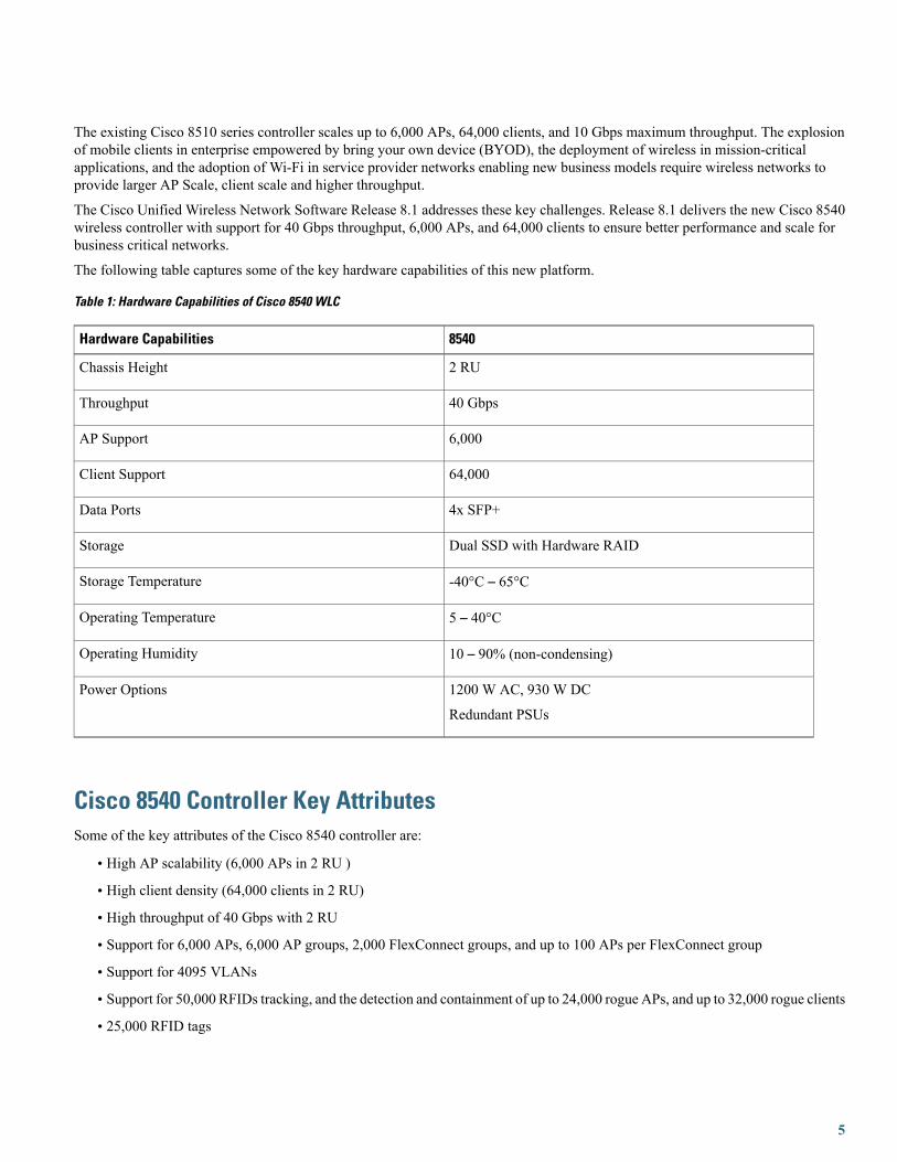
The following table captures some of the key hardware capabilities of this new platform.
Table 1: Hardware Capabilities of Cisco 8540 WLC
8540Hardware Capabilities
2 RUChassis Height
40 GbpsThroughput
6,000AP Support
64,000Client Support
4x SFP+Data Ports
Dual SSD with Hardware RAIDStorage
-40°C – 65°CStorage Temperature
5 – 40°COperating Temperature
10 – 90% (non-condensing)Operating Humidity
1200 W AC, 930 W DC
Redundant PSUs
Power Options
Cisco 8540 Controller Key AttributesSome of the key attributes of the Cisco 8540 controller are:
• High AP scalability (6,000 APs in 2 RU )
• High client density (64,000 clients in 2 RU)
• High throughput of 40 Gbps with 2 RU
• Support for 6,000 APs, 6,000 AP groups, 2,000 FlexConnect groups, and up to 100 APs per FlexConnect group
• Support for 4095 VLANs
• Support for 50,000 RFIDs tracking, and the detection and containment of up to 24,000 rogue APs, and up to 32,000 rogue clients
• 25,000 RFID tags
5

• 3,20,000 AVC Flows
• PMK cache size of 64,000
• High availability with sub-second AP and client SSO
• TrustSec SXP Support
• Support of all AP modes of operation (Local, FlexConnect, Monitor, Rogue Detector, Sniffer, Bridge, and Flex+Bridge)
• Right to Use (RTU) licensing for ease of license enablement and ongoing licensing operations
The following table shows the Cisco enterprise campus controllers comparison at a glance:
Table 2: Cisco Enterprise Campus Controllers comparison
751085108540Attributes
Central site controller for largenumber of distributed,controller-less branches
Enterprise Large campus + SPWi-Fi
Full Scale Branch
Enterprise Large campus + SPWi-Fi
Full Scale Branch
Deployment type
FlexConnect, Flex+BridgeAll AP modesAll AP modesOperational Modes
6,000 APs
64,000 clients
6,000 APs
64,000 clients
6,000 APs
64,000 clients
Maximum Scale
300 – 6,000300 – 6,0001 – 6,000AP Count Range
Right to Use (with EULA)Right to Use (with EULA)Right to Use (with EULA)Licensing
2 x 10 G ports2 x 10 G ports4 x 10 G portsConnectivity
AC/DC dual redundantAC/DC dual redundant1200 W AC, 930 W DC
Dual redundantHot-swappable PSU
Power
2,0002,0002,000Maximum Number ofFlexConnect Groups
100100100MaximumNumber of APs perFlexConnect Group
32,00032,00024,000Maximum Number of RogueAPs Management
24,00024,00032,000Maximum Number of RogueClients Management
50,00050,00050,000Maximum Number of RFID
6
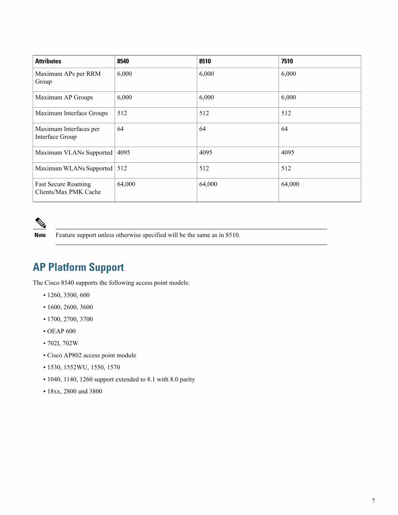
751085108540Attributes
6,0006,0006,000Maximum APs per RRMGroup
6,0006,0006,000Maximum AP Groups
512512512Maximum Interface Groups
646464Maximum Interfaces perInterface Group
409540954095Maximum VLANs Supported
512512512MaximumWLANs Supported
64,00064,00064,000Fast Secure RoamingClients/Max PMK Cache
Feature support unless otherwise specified will be the same as in 8510.Note
AP Platform SupportThe Cisco 8540 supports the following access point models:
• 1260, 3500, 600
• 1600, 2600, 3600
• 1700, 2700, 3700
• OEAP 600
• 702I, 702W
• Cisco AP802 access point module
• 1530, 1552WU, 1550, 1570
• 1040, 1140, 1260 support extended to 8.1 with 8.0 parity
• 18xx, 2800 and 3800
7
Platform Components
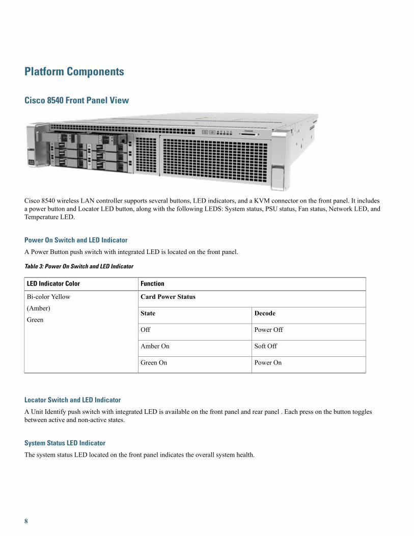
Cisco 8540 Front Panel View
Cisco 8540 wireless LAN controller supports several buttons, LED indicators, and a KVM connector on the front panel. It includesa power button and Locator LED button, along with the following LEDS: System status, PSU status, Fan status, Network LED, andTemperature LED.
Power On Switch and LED Indicator
A Power Button push switch with integrated LED is located on the front panel.
Table 3: Power On Switch and LED Indicator
FunctionLED Indicator Color
Card Power StatusBi-color Yellow
(Amber)
GreenDecodeState
Power OffOff
Soft OffAmber On
Power OnGreen On
Locator Switch and LED Indicator
A Unit Identify push switch with integrated LED is available on the front panel and rear panel . Each press on the button togglesbetween active and non-active states.
System Status LED Indicator
The system status LED located on the front panel indicates the overall system health.
8
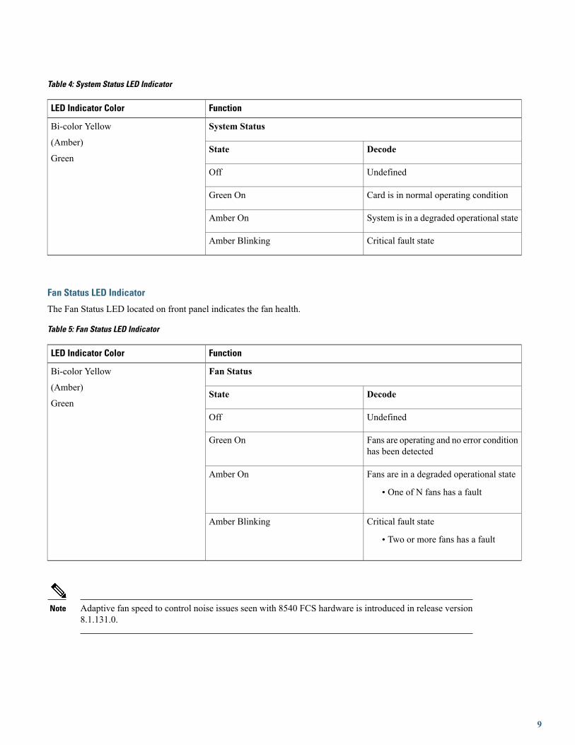
Table 4: System Status LED Indicator
FunctionLED Indicator Color
System StatusBi-color Yellow
(Amber)
GreenDecodeState
UndefinedOff
Card is in normal operating conditionGreen On
System is in a degraded operational stateAmber On
Critical fault stateAmber Blinking
Fan Status LED Indicator
The Fan Status LED located on front panel indicates the fan health.
Table 5: Fan Status LED Indicator
FunctionLED Indicator Color
Fan StatusBi-color Yellow
(Amber)
GreenDecodeState
UndefinedOff
Fans are operating and no error conditionhas been detected
Green On
Fans are in a degraded operational state
• One of N fans has a fault
Amber On
Critical fault state
• Two or more fans has a fault
Amber Blinking
Adaptive fan speed to control noise issues seen with 8540 FCS hardware is introduced in release version8.1.131.0.
Note
9
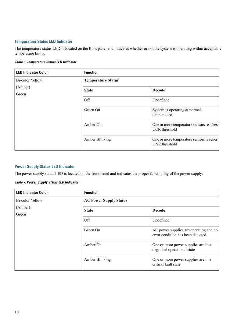
Temperature Status LED Indicator
The temperature status LED is located on the front panel and indicates whether or not the system is operating within acceptabletemperature limits.
Table 6: Temperature Status LED Indicator
FunctionLED Indicator Color
Temperature StatusBi-color Yellow
(Amber)
GreenDecodeState
UndefinedOff
System is operating at normaltemperature
Green On
One or more temperature sensors reachesUCR threshold
Amber On
One or more temperature sensors reachesUNR threshold
Amber Blinking
Power Supply Status LED Indicator
The power supply status LED is located on the front panel and indicates the proper functioning of the power supply.
Table 7: Power Supply Status LED Indicator
FunctionLED Indicator Color
AC Power Supply StatusBi-color Yellow
(Amber)
GreenDecodeState
UndefinedOff
AC power supplies are operating and noerror condition has been detected
Green On
One or more power supplies are in adegraded operational state
Amber On
One or more power supplies are in acritical fault state
Amber Blinking
10

Network Link LED Indicator
The network LED is located on the front panel and indicates if any of the on-board networking ports are connected and operating.
Table 8: Network Link LED Indicator
FunctionLED Indicator Color
Network Link StatusSingle Color
GreenDecodeState
UndefinedOff
Link on any of the ports, but no activityGreen On
Activity on any of the portsGreen Blinking
Front Panel KVM Break-out Connector
A single female connector provides access to video, two USB ports for keyboard and mouse, and an RS-232C console serial port.
An external breakout connector to industry standard interfaces is required. The following figure shows an example cable.
The interfaces for the cable are:
1 Front panel KVM/Console connector
2 DB9 serial port connector
3 Dual Type-A USB 2.0 connectors
4 DB15 Video connector
11

Cisco 8540 WLC Rear Panel View
The rear panel has the following interfaces:
1 Two Type-A 3.0 USB ports
2 IMC port 10/100/1000 Base-T
To setup the CIMC interface:
• Connect the CIMC cable.
• To enable DHCP to set the IP, use the command imm dhcp enable.
• If DHCP is not available, use the command imm address <ip address> <net mask> <gateway ip>.
• To view the IP and details, use the command imm summary.
12
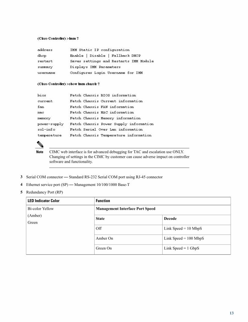
CIMC web interface is for advanced debugging for TAC and escalation use ONLY.Changing of settings in the CIMC by customer can cause adverse impact on controllersoftware and functionality.
Note
3 Serial COM connector— Standard RS-232 Serial COM port using RJ-45 connector
4 Ethernet service port (SP)—Management 10/100/1000 Base-T
5 Redundancy Port (RP)
FunctionLED Indicator Color
Management Interface Port SpeedBi-color Yellow
(Amber)
GreenDecodeState
Link Speed = 10 MbpSOff
Link Speed = 100 MbpSAmber On
Link Speed = 1 GbpSGreen On
13

FunctionLED Indicator Color
Management Interface Port StatusBi-color Yellow
(Amber)
GreenDecodeState
No LinkOff
LinkGreen On
Traffic PresentBlinking
6 VGA Connector— Rear panel has a standard VGA port using a female D-Sub-15 Connector
7 ID Switch and LED
8 Four 1/10 G Management and Network ports
Functional DefinitionLED
LED: (Amber) On indicates power is goodPwr OK
LED: (Amber) On indicates 10 G mode
LED: Off indicates 1 G mode
10 G
Green On—Link is up in 10Gbe Mode
Amber On—Link is up in 1 Gbe Mode
Off—Link status is down
Port-n Link Status
LED: (Green) blinking indicates link activityPort-n Link Activity
14
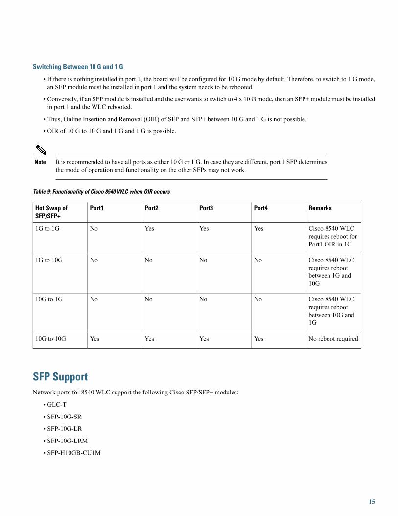
Switching Between 10 G and 1 G
• If there is nothing installed in port 1, the board will be configured for 10 G mode by default. Therefore, to switch to 1 G mode,an SFP module must be installed in port 1 and the system needs to be rebooted.
• Conversely, if an SFP module is installed and the user wants to switch to 4 x 10 Gmode, then an SFP+ module must be installedin port 1 and the WLC rebooted.
• Thus, Online Insertion and Removal (OIR) of SFP and SFP+ between 10 G and 1 G is not possible.
• OIR of 10 G to 10 G and 1 G and 1 G is possible.
It is recommended to have all ports as either 10 G or 1 G. In case they are different, port 1 SFP determinesthe mode of operation and functionality on the other SFPs may not work.
Note
Table 9: Functionality of Cisco 8540 WLC when OIR occurs
RemarksPort4Port3Port2Port1Hot Swap ofSFP/SFP+
Cisco 8540 WLCrequires reboot forPort1 OIR in 1G
YesYesYesNo1G to 1G
Cisco 8540 WLCrequires rebootbetween 1G and10G
NoNoNoNo1G to 10G
Cisco 8540 WLCrequires rebootbetween 10G and1G
NoNoNoNo10G to 1G
No reboot requiredYesYesYesYes10G to 10G
SFP SupportNetwork ports for 8540 WLC support the following Cisco SFP/SFP+ modules:
• GLC-T
• SFP-10G-SR
• SFP-10G-LR
• SFP-10G-LRM
• SFP-H10GB-CU1M
15
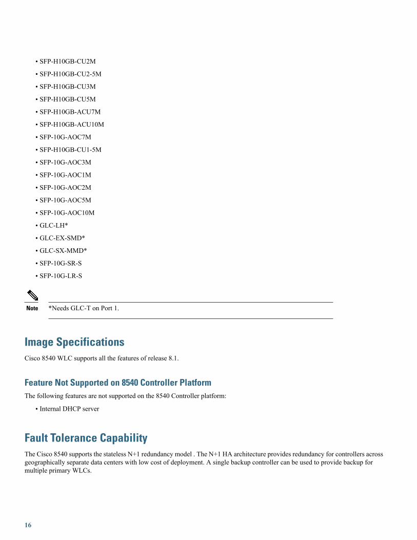
• SFP-H10GB-CU2M
• SFP-H10GB-CU2-5M
• SFP-H10GB-CU3M
• SFP-H10GB-CU5M
• SFP-H10GB-ACU7M
• SFP-H10GB-ACU10M
• SFP-10G-AOC7M
• SFP-H10GB-CU1-5M
• SFP-10G-AOC3M
• SFP-10G-AOC1M
• SFP-10G-AOC2M
• SFP-10G-AOC5M
• SFP-10G-AOC10M
• GLC-LH*
• GLC-EX-SMD*
• GLC-SX-MMD*
• SFP-10G-SR-S
• SFP-10G-LR-S
*Needs GLC-T on Port 1.Note
Image SpecificationsCisco 8540 WLC supports all the features of release 8.1.
Feature Not Supported on 8540 Controller PlatformThe following features are not supported on the 8540 Controller platform:
• Internal DHCP server
Fault Tolerance CapabilityThe Cisco 8540 supports the stateless N+1 redundancy model . The N+1 HA architecture provides redundancy for controllers acrossgeographically separate data centers with low cost of deployment. A single backup controller can be used to provide backup formultiple primary WLCs.
16

For more information on this model of redundancy, refer tohttp://www.cisco.com/c/en/us/td/docs/wireless/technology/hi_avail/N1_High_Availability_Deployment_Guide/N1_HA_Overview.html.
AP and Client SSOHigh Availability Stateful Switchover (SSO) model provides a Box-to-Box redundancy with one controller in active state and anothercontroller in hot standby state. The SSO model monitors the health of the active controller via a redundant (HA) port. Cisco 8540wireless LAN controller has a failover RP Port.
The configuration on the active controller is synched to the standby controller using the redundant port. In HA, both controllers sharethe same set of configuration including the IP address of the management interface. The AP's CAPWAP state (for APs in RUN state)is also synched. As a result, APs do not go into Discovery state when the active controller fails. Also, a client's information is syncedto the standby WLC when the client associates to the WLC or the client’s parameters change. Fully authenticated clients, that is, theones in Run state, are synced to the standby. Thus, client re-association is avoided on switchover, making the failover seamless forthe APs as well as for the clients, resulting in zero client service downtime and no SSID outage.
For more information on the SSO feature and the supported topologies, refer to the High Availability deployment Guide.
17

Connecting Cisco 8540 SSO Pair to the Wired Network
It is recommended to connect to a VSS pair and spread the links in each port-channel between the two physical switches to preventa WLC switchover upon a failure of one of the VSS switches.
Customer Replaceable UnitsCisco 8540 wireless LAN controller has a minimal amount of separate orderable items, including all of the following:
• Power supply
• SSD Hard Disk Drive (HDD)
• HDD and power supply are hot-swappable on the Cisco 8540 WLC
The power supply units are field replaceable.Note
Link Aggregation (LAG)A single LAG across the 4 x 10 G interfaces is supported in software versions 8.1 and later. LACP and PAgP are not supported onthe controller.
18
Inter-Platform Mobility and Guest Anchor SupportGuest anchor capability with:
• Cisco WLC 2504/5508 / 8510 / 7510 / WISM2 running as a foreign controller (EOIP Tunnel)
• Cisco 5520 / 8540 WLC running as a foreign controller (EOIP Tunnel)
• Cisco 5760 WLC running as a foreign controller with new mobility turned on (CAPWAP Tunnel)
Foreign controller to a guest anchor which is a:
• Cisco WLC 2504/5508 / 8510 / 7510 / WISM2 (EOIP Tunnel)
• Cisco 5520 / 8540 WLC (EOIP Tunnel)
• Cisco 5760 WLC with new mobility turned on (CAPWAP Tunnel)
CAPWAP has native management plane encryption and optional data payload encryption.
Infrastructure MulticastMulticast support is enabled in the Cisco 8540 controller with the following restrictions:
• If all APs on the 8540 controller are configured in Local mode, Multicast-Multicast will be the default mode and all featuresare supported (for example, VideoStream).
If the APs are configured as a mix of Local mode and FlexConnect mode:
• If IPv6 is required on the FlexConnect APs:
• Disable Global Multicast Mode and change to Multicast-Unicast mode.
• IPv6 / GARP will work on FlexConnect and Local mode APs, but Multicast data and the VideoStream feature will bedisabled.
• IPv6 / GARP is not required on FlexConnect APs:
• Change the mode to Multicast-Multicast and enable Global Multicast Mode and IGMP / MLD snooping.
• IPv6, GARP, Multicast Data, and VideoStream are supported on local mode APs.
New Mobility and MC SupportCisco 8540 supports the new mobility functionality to be compatible with inter-platform IRCM and guest anchor support. Thisplatform will not function as an MC.
Look and Feel of the Cisco 8540 Wireless LAN ControllerThe Cisco 8540 controller enables console redirect by default with baud rate 9600, simulating a VT100 terminal with no flow control.The 8540 controller has the same boot sequence as existing controller platforms.
19

Boot Up and Initial Configuration• Initial Boot Sequence
• Boot Options
• Loading the OS and Boot Loader
• Loading Controller Services
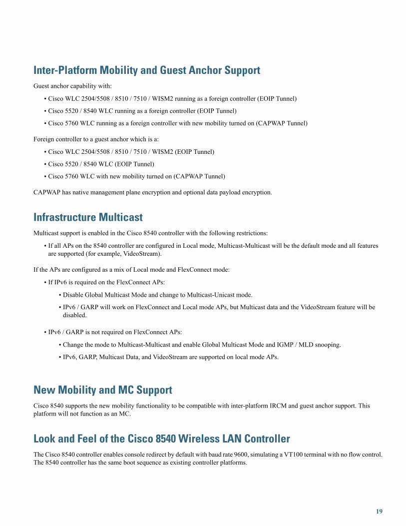
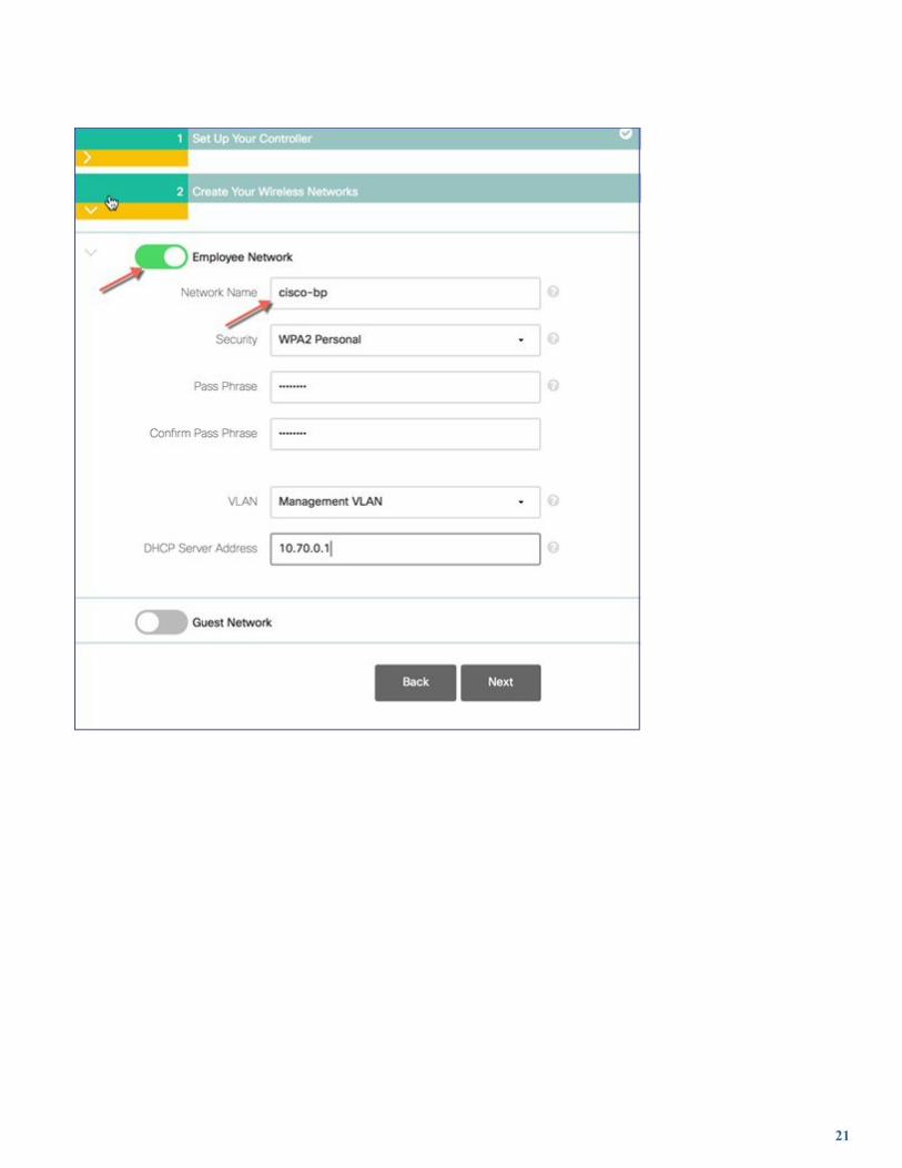
Initial Controller ConfigurationConfiguration Wizard— As with all other controller platforms, initial boot up requires configuration using the Wizard menu.
WLAN Express Setup— As with all other controller platforms, 8540 WLC also supports the Express WLAN Setup over wiredEthernet connection.
20
21
22

Monitoring and Best PracticesThis platform supports the Monitoring Dashboard and the Upgrade audit workflow view with release 8.1.
Management Web UIThe management web interface has the same look and feel as existing Cisco wireless LAN controllers.
23

24
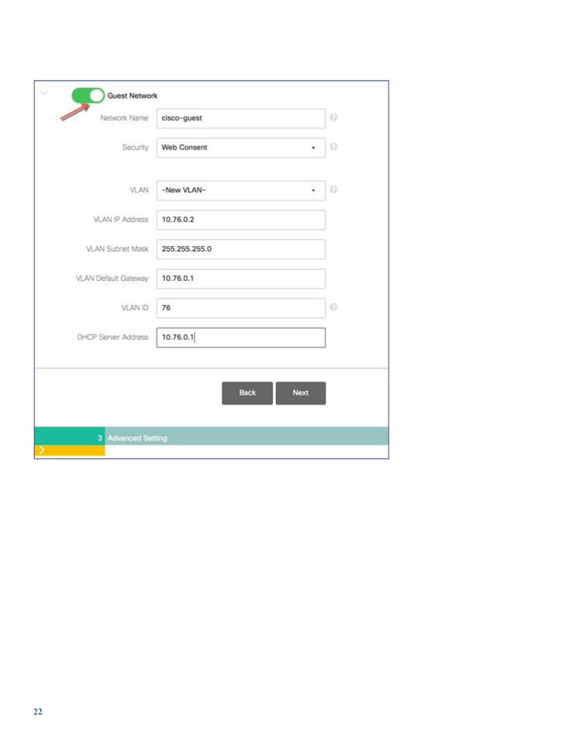
Out of Band Management on Service PortStarting release 8.2 the Service Port capability on the Cisco 8540Wireless LANController has been enhanced to support the followingmanagement services:
• HTTP/HTTPS web-based access
• SNMP polling v2 and v3
• Syslog
• SSH or Telnet
These services shall be supported in a non-HA topology only in this release.
Service PortThe service port is a 10/100/1000 Base-T management port located on the rear panel Port 4 in the figure shows the Service Port onthe Cisco 8540 Wireless LAN Controller.
25

Service Port ConfigurationThe IP address assigned to the service port must be in a non-routable subnet different from theManagement subnet. It can be assigneddynamically or statically as shown in the configuration below. There is no change in the service port configuration itself and thecommands below are for your reference.
Use the following commands to define the Service port interface with an IPv4 address:
Dynamic assignment of IPv4 address on the Service Port:
• To configure the DHCP server:config interface dhcp service-port enable
• To disable the DHCP server:config interface dhcp service-port disable
• To configure a static IPv4 address on the Service Port use the following command:config interface address service-port ip-address netmask
• To add an IPv4 route to allow out-of-band management of the controller from a remote workstation:config route add network-ip-address ip-netmask gateway
• To remove the IPv4 route on the controller:config route delete network-ip-address
Use the following commands to define the Service port interface with an IPv6 address:
• To configure the service port using slacc:config ipv6 interface slacc service-port enable
• To disable the service port using slacc:config ipv6 interface slacc service-port disable
• To configure the IPv6 address:config ipv6 interface address service-port ipv6-address prefix-length
26
• To add an IPv6 route to allow out-of-band management of the controller from a remote workstation:config ipv6 route add network_ipv6_address prefix-length ipv6_gw_addr
• To remove the IPv4 route on the controller:config ipv6 route delete network_ipv6_address
• To verify the status of the service port after configuration
show interface detailed service-port
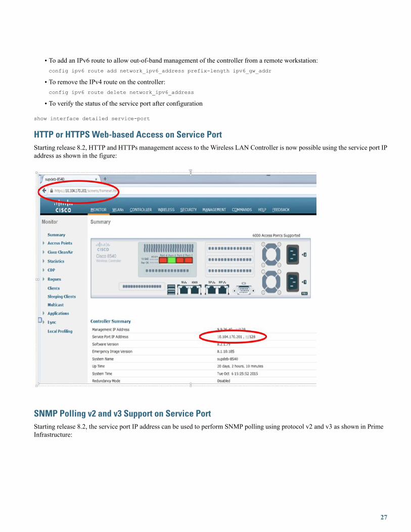
HTTP or HTTPS Web-based Access on Service PortStarting release 8.2, HTTP and HTTPs management access to the Wireless LAN Controller is now possible using the service port IPaddress as shown in the figure:
SNMP Polling v2 and v3 Support on Service PortStarting release 8.2, the service port IP address can be used to perform SNMP polling using protocol v2 and v3 as shown in PrimeInfrastructure:
27

Syslog Server on Service PortStarting release 8.2, the Syslog service can be accessed via the service port.
28
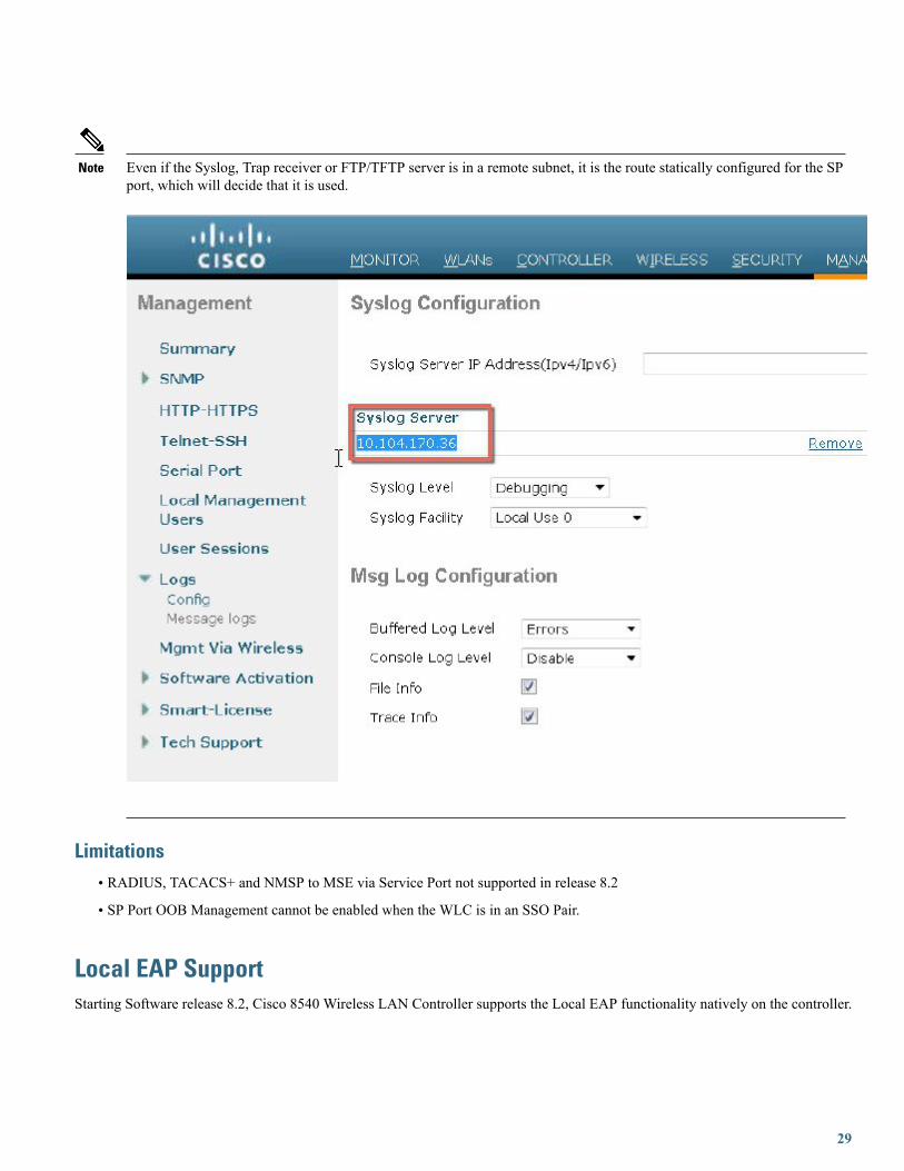
Even if the Syslog, Trap receiver or FTP/TFTP server is in a remote subnet, it is the route statically configured for the SPport, which will decide that it is used.
Note
Limitations• RADIUS, TACACS+ and NMSP to MSE via Service Port not supported in release 8.2
• SP Port OOB Management cannot be enabled when the WLC is in an SSO Pair.
Local EAP SupportStarting Software release 8.2, Cisco 8540 Wireless LAN Controller supports the Local EAP functionality natively on the controller.
29
Local EAP is an authentication method that allows users and wireless clients to be authenticated locally on the controller. It is designedfor use in remote offices that want to maintain connectivity to wireless clients when the backend system becomes disrupted or theexternal authentication server goes down. When you enable local EAP, the controller serves as the authentication server and the localuser database, so it removes dependence on an external authentication server. Local EAP retrieves user credentials from the localuser database or the LDAP backend database to authenticate users. Local EAP supports LEAP, EAP-FAST, EAP-TLS,PEAPv0/MSCHAPv2, and PEAPv1/GTC authentication between the controller and wireless clients.
The configuration of Local EAP remains the same as on existing WLCs. A Local EAP Server Configuration Example can be foundat http://www.cisco.com/c/en/us/support/docs/wireless-mobility/wlan-security/91628-uwn-loc-eap-svr-config.html%23maintask1
Wired Guest Access SupportStarting Software release 8.2, Cisco 8540 Wireless LAN Controller supports the Wired Guest Access functionality.
A growing number of companies recognize the need to provide Internet access to its customers, partners, and consultants when theyvisit their facilities. IT managers can provide wired and wireless secured and controlled access to the Internet for guests on the samewireless LAN controller. Guest users must be allowed to connect to designated Ethernet ports and access the guest network asconfigured by the administrator after they complete the configured authentication methods. Wireless guest users can easily connectto the WLAN Controllers with the current guest access features. This provides a unified wireless and wired guest access experienceto the end users.
Wired guest ports are provided in a designated location and plugged into an access switch. The configuration on the access switchputs these ports in one of the wired guest Layer 2 VLANs.
Two separate solutions are available to the customers:
A single WLAN controller (VLAN Translation mode)–the access switch trunks the wired guest traffic in the guest VLAN to theWLAN controller that provides the wired guest access solution. This controller carries out the VLAN translation from the ingresswired guest VLAN to the egress VLAN.
Two WLAN controllers (Auto Anchor mode) - the access switch trunks the wired guest traffic to a local WLAN controller (thecontroller nearest to the access switch). This local WLAN controller anchors the client onto a Demilitarized Zone (DMZ) AnchorWLAN controller that is configured for wired and wireless guest access. After a successful handoff of the client to the DMZ anchorcontroller, the DHCP IP address assignment, authentication of the client, and so on are handled in the DMZWLC. After it completesthe authentication, the client is allowed to send and receive traffic.
The configuration of Wired Guest Access remains the same as on existing WLCs. A Wired Guest Access Configuration Examplecan be found at http://www.cisco.com/c/en/us/support/docs/wireless-mobility/wireless-lan-wlan/99470-config-wiredguest-00.html
Licensing8540 Wireless LAN Controller supports Right to Use (RTU) licensing model similar to the Cisco Flex 7500 and Cisco 8500 seriescontrollers. This is an Honor-based licensing scheme that allows AP licenses to be enabled on supported controllers with End UserLicense Agreement (EULA) acceptance. The RTU license scheme simplifies addition, deletion, or the transfer of AP adder licensesin the field by eliminating the need for an additional step, additional tools, or access to Cisco.com for PAK license or return materialsauthorization (RMA) transfers.
Evaluation licenses are valid for 90 days. Notifications will be generated to inform you to buy a permanent license starting 15 daysprior to the evaluation license expiration.
If you havemore APs connected than those purchased, the licensing status for the controller trackedwithin the Cisco Prime Infrastructurewill turn red.
For more information on the RTU License model, refer to the Cisco Right to Use Licensing (RTU) document.
30
Smart Licensing is also available, for more information refer to http://www.cisco.com/c/en/us/td/docs/wireless/technology/mesh/8-2/b_Smart_Licensing_Deployment_Guide.html
License TypesThese are the three license types:
• Permanent licenses—The AP count is programmed into NVM while manufacturing. These licenses are transferable.
• Adder access point count licenses—Can be activated through the acceptance of the EULA. These licenses are transferable.
• Evaluation licenses—Used for demo and/or trial periods, are valid for 90 days, and default to the full capacity of the controller.The evaluation license can be activated at any time using a CLI command.
Licensing Model Features• Two Base Bundle SKUs: AIR-CT8540-K9 and AIR-CT8540-1K-K9
• Portability of licenses between 5520 and 8540 wireless LAN controllers
• No separate HA-SKU UDI
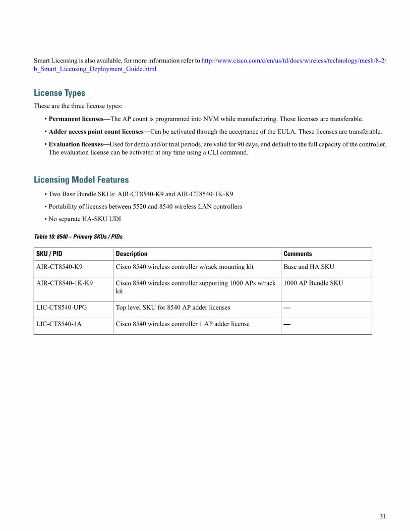
Table 10: 8540 – Primary SKUs / PIDs
CommentsDescriptionSKU / PID
Base and HA SKUCisco 8540 wireless controller w/rack mounting kitAIR-CT8540-K9
1000 AP Bundle SKUCisco 8540 wireless controller supporting 1000 APs w/rackkit
AIR-CT8540-1K-K9
—Top level SKU for 8540 AP adder licensesLIC-CT8540-UPG
—Cisco 8540 wireless controller 1 AP adder licenseLIC-CT8540-1A
31

© 2015 Cisco Systems, Inc. All rights reserved.

Europe HeadquartersAsia Pacific HeadquartersAmericas HeadquartersCisco Systems International BVAmsterdam, The Netherlands
Cisco Systems (USA) Pte. Ltd.Singapore
Cisco Systems, Inc.San Jose, CA 95134-1706USA
Cisco has more than 200 offices worldwide. Addresses, phone numbers, and fax numbers are listed on theCisco Website at www.cisco.com/go/offices.