Embed Size (px)
Citation preview
MICHIGAN UTILITY COORDINATION COMMITTEE’S GEOSPATIAL UTILITY INFRASTRUCTURE DATA EXCHANGE 2014 PILOT INITIATIVE
March 2015
Report Prepared by:
Eric Barden, P.S.
Principal | Geospatial Services
MUCC GUIDE
Contents
1EXECUTIVESUMMARY..................................................................................................................................................1
1.1VALUEPROPOSITION.............................................................................................................................................................................11.22014GUIDEPILOTINITIATIVEANDGOALS.......................................................................................................................................11.2.1Goals....................................................................................................................................................................................................11.2.2AnticipatedBenefits.....................................................................................................................................................................1
1.3OUTCOME............................................................................................................................................................................................21.3.1KeyFindings....................................................................................................................................................................................21.3.2CostSummary.................................................................................................................................................................................3
22014GUIDEPILOTINITIATIVE..................................................................................................................................4
2.1GUIDEBACKGROUND.....................................................................................................................................................................42.2KICKOFFANDPILOTPROJECTIDENTIFICATION................................................................................................................52.3DATAACQUISITIONSTRATEGIES..............................................................................................................................................62.3.1ConsumersEnergyPilotProjects............................................................................................................................................62.3.2AT&TPilotProjects.....................................................................................................................................................................112.3.3DTEEnergyPilotProjects.......................................................................................................................................................13
2.4PILOTPROJECTRESULTS...........................................................................................................................................................162.4.1GUIDEKeyFindings...................................................................................................................................................................162.4.2MajorBenefits...............................................................................................................................................................................202.4.3DataAcquisitionLessonsLearned.......................................................................................................................................262.4.4Concerns..........................................................................................................................................................................................292.4.5CostImpactSummary...............................................................................................................................................................32
2.5OVERALLCOSTBENEFIT...........................................................................................................................................................352.5.1Conclusion......................................................................................................................................................................................37
3FUTUREOFGUIDE.......................................................................................................................................................38
3.1CONSIDERATIONSFORTHEFUTURE..........................................................................................................................................383.1.1GUIDERequirementsDocumentImprovement.............................................................................................................393.1.2DataManagement......................................................................................................................................................................403.1.3GUIDEProcessImprovement.................................................................................................................................................403.1.4IntendedUse..................................................................................................................................................................................413.1.5Accuracy..........................................................................................................................................................................................413.1.6Safety................................................................................................................................................................................................423.1.7Training...........................................................................................................................................................................................423.1.8DataSecurity.................................................................................................................................................................................423.1.9StatewideStandardization.....................................................................................................................................................42
ACKNOWLEDGEMENTS.................................................................................................................................................44
REFERENCES.....................................................................................................................................................................45
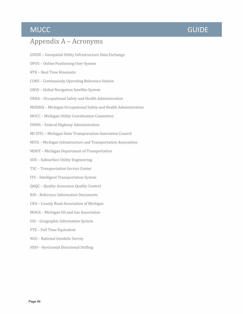
APPENDIXA–ACRONYMS............................................................................................................................................46
MUCC GUIDE APPENDIXB–LISTOFFIGURES.................................................................................................................................47
APPENDIXC–GUIDEREQUIREMENTSDOCUMENT.............................................................................................48
APPENDIXD–MUCCGOALS.........................................................................................................................................53
APPENDIXE–MUCCMEETINGMINUTES................................................................................................................55
APPENDIXF–FHWAMI‐STICAPPROVALPACKAGE.............................................................................................60
APPENDIXG–SAMPLEDATADELIVERYTEMPLATEINMSEXCEL..................................................................66
MUCC GUIDE
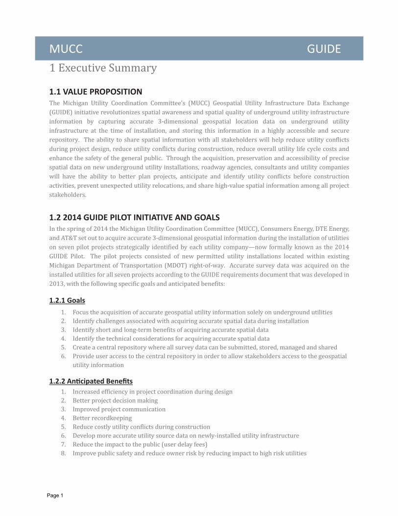
1.1 VALUE PROPOSITION
1.2 2014 GUIDE PILOT INITIATIVE AND GOALS
1.2.1 Goals
1.2.2 An cipated Bene ts
Page 1
MUCC GUIDE 1.3 OUTCOME
1.3.1 Key Findings
Page 2
MUCC GUIDE
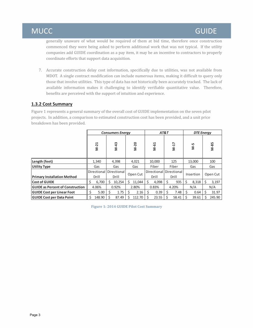
1.3.2 Cost Summary
Figure 1: 2014 GUIDE Pilot Cost Summary
M21
M43
M20
M61
M17
M5
M85
Length (feet) 1,340 4,398 4,021 10,000 125 13,000 100Utility Type Gas Gas Gas Fiber Fiber Gas Gas
Primary InstallationMethodDirectional
DrillDirectional
DrillOpen Cut
DirectionalDrill
DirectionalDrill
Insertion Open Cut
Cost of GUIDE 6,700$ 10,254$ 11,044$ 4,098$ 935$ 8,318$ 3,197$ GUIDE as Percent of Construction 4.06% 0.92% 2.80% 0.83% 4.20% N/A N/AGUIDE Cost per Linear Foot 5.00$ 1.75$ 2.16$ 0.39$ 7.48$ 0.64$ 31.97$ GUIDE Cost per Data Point 148.90$ 87.49$ 112.70$ 23.55$ 58.41$ 39.61$ 245.90$
Consumers Energy DTE EnergyAT&T
Page 3
MUCC GUIDE
2.1 GUIDE BACKGROUND
“Considerations in the Use of GPS Technology for Damage Prevention” originally presented by (W.R (Bill)Byrd, P.E., RCP Inc.).
“Geospatial DataCollection Requirements for Permitted Utility Installations Performed within the Michigan Department ofTransportation (MDOT) right of way (dated April 22, 2013).”
Page 4
MUCC GUIDE
2.2 KICKOFF AND PILOT PROJECT IDENTIFICATION
Page 5
MUCC GUIDE
Consumers Energy
AT&T
DTE Energy
2.3 DATA ACQUISITION STRATEGIES
2.3.1 Consumers Energy Pilot Projects
Page 6
MUCC GUIDE
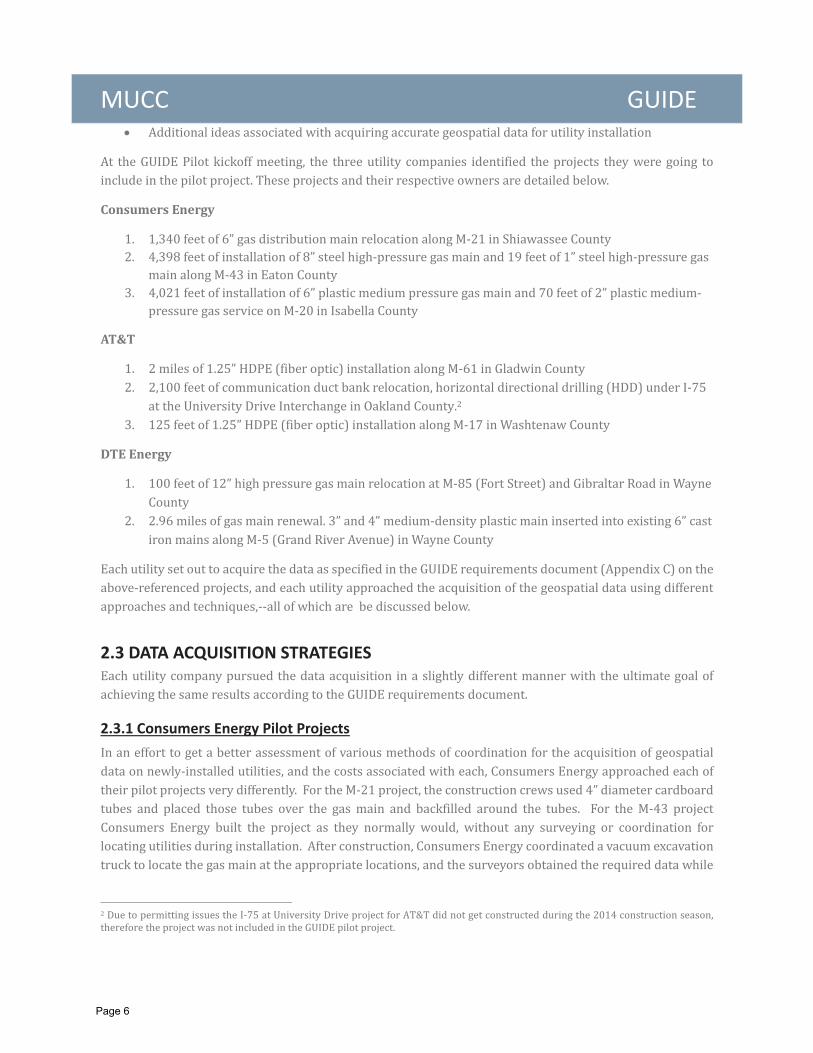
M 21 Shiawassee County (6” gas main relocation)
Figure 2: Cardboard Tubes Placed over Gas Main
Figure 3: Surveying Utility inside Cardboard Tube
Page 7
MUCC GUIDE
Conclusion
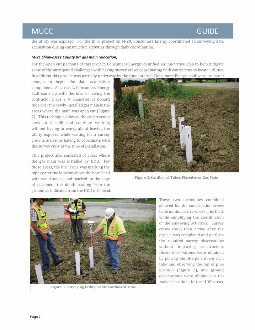
M 43 Eaton County (8” S HP gas main installation)
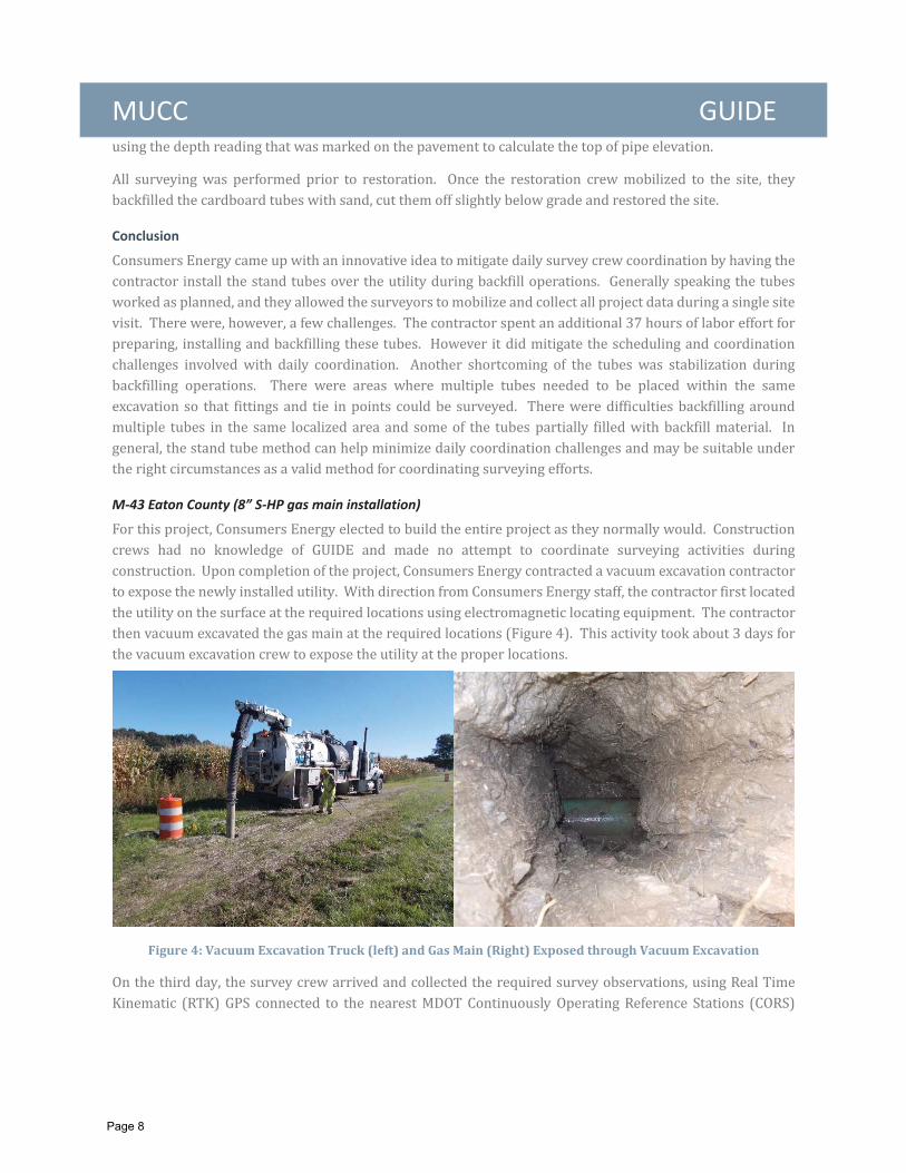
Figure 4: Vacuum Excavation Truck (left) and Gas Main (Right) Exposed through Vacuum Excavation
Page 8
MUCC GUIDE
Conclusion
Figure 5: Survey Crew Obtaining Positional Data on Exposed Utility
Page 9
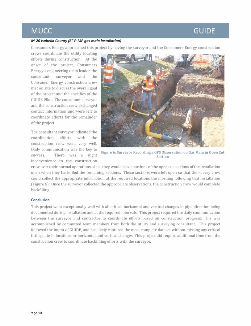
MUCC GUIDE M 20 Isabella County (6” P MP gas main installation)
Conclusion
Figure 6: Surveyor Recording a GPS Observation on Gas Main in Open CutSection
Page 10
MUCC GUIDE 2.3.2 AT&T Pilot Projects
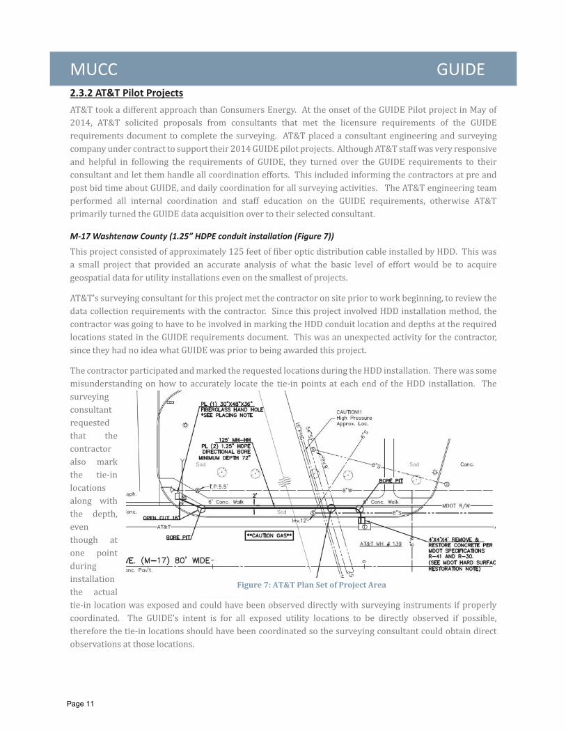
M 17Washtenaw County (1.25” HDPE conduit installation (Figure 7))
Figure 7: AT&T Plan Set of Project Area
Page 11
MUCC GUIDE
Conclusion
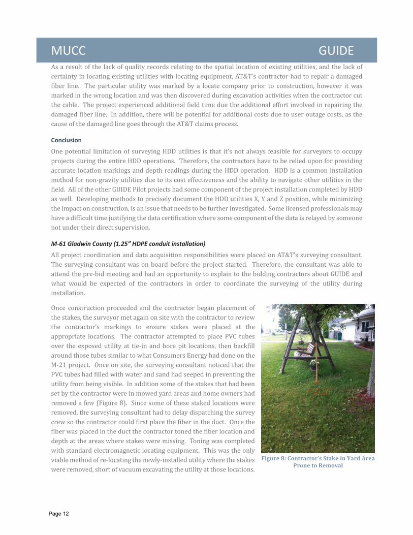
M 61 Gladwin County (1.25” HDPE conduit installation)
Figure 8: Contractor’s Stake in Yard AreaProne to Removal
Page 12
MUCC GUIDE
Conclusion
2.3.3 DTE Energy Pilot Projects
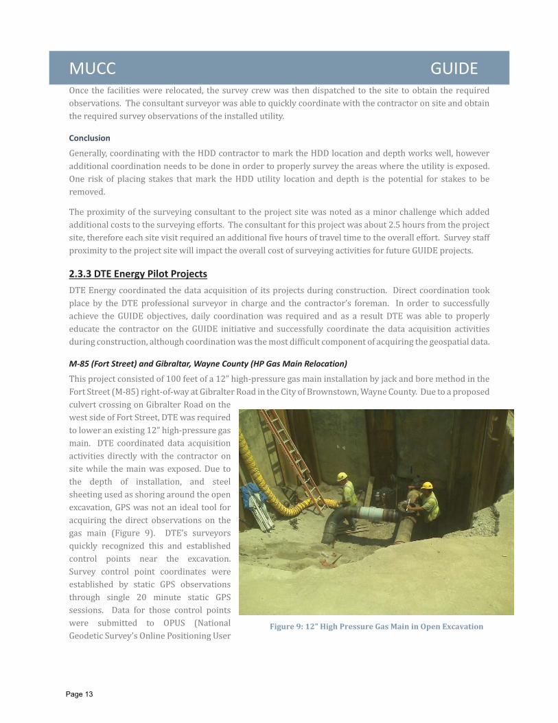
M 85 (Fort Street) and Gibraltar, Wayne County (HP Gas Main Relocation)
Figure 9: 12" High Pressure Gas Main in Open Excavation
Page 13
MUCC GUIDE
Conclusion
Page 14
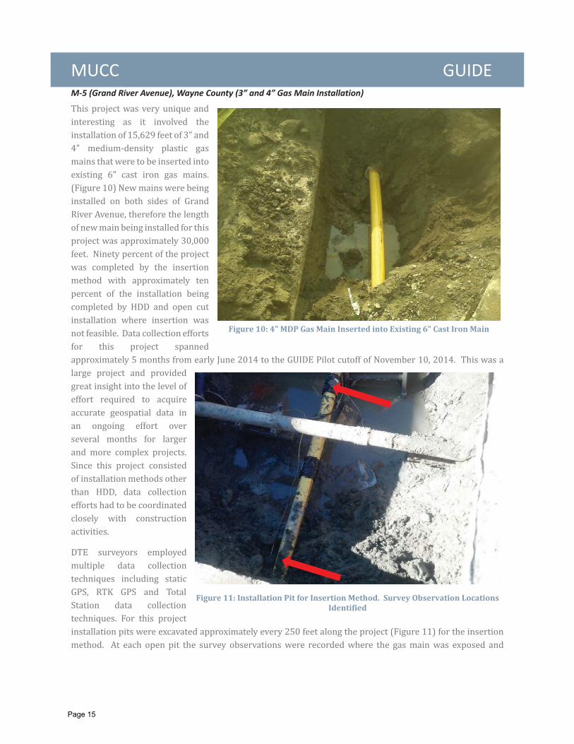
MUCC GUIDE M 5 (Grand River Avenue), Wayne County (3” and 4” Gas Main Installation)
Figure 10: 4" MDP Gas Main Inserted into Existing 6" Cast Iron Main
Figure 11: Installation Pit for Insertion Method. Survey Observation LocationsIdentified
Page 15
MUCC GUIDE
Conclusion
2.4 PILOT PROJECT RESULTS
2.4.1 GUIDE Key Findings
1. Further Development of the GUIDE Requirements Document
a. Expand on the requirement for changes in geometry
Page 16
MUCC GUIDE
b. Revise data format requirement and expand data attribution
c. Develop the data submittal, QA/QC review, data acceptance and final upload process
Page 17

MUCC GUIDE
2. Potential for Significant Roadway Agency Impacts
a. Data management and IT resource allocation
b. Need for additional personnel resources
c. Resource commitment to long termmaintenance of the data
Page 18
MUCC GUIDE
3. Training Requirements
4. Survey Staff Proximity to Projects
5. Coordination of Surveying Efforts
Page 19
MUCC GUIDE 6. Development of Contract Specific Language
7. Lack of Supporting Utility Conflict Cost Data
2.4.2 Major Bene ts
1. Identify Utility Conflicts Early
Page 20
MUCC GUIDE
2. Reduce Future Utility Conflicts During Construction
Page 21
MUCC GUIDE
3. Utilize Accurate Utility Source Data for Better Design Coordination
Page 22
MUCC GUIDE
4. Reduce Public Impact
Page 23
MUCC GUIDE
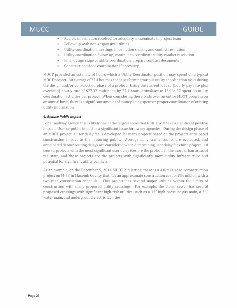
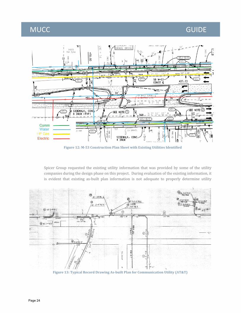
Figure 13: Typical Record Drawing As built Plan for Communication Utility (AT&T)
Figure 12: M 53 Construction Plan Sheet with Existing Utilities Identified
Page 24
MUCC GUIDE
5. Improved Public Safety and Reduced Owner Risk
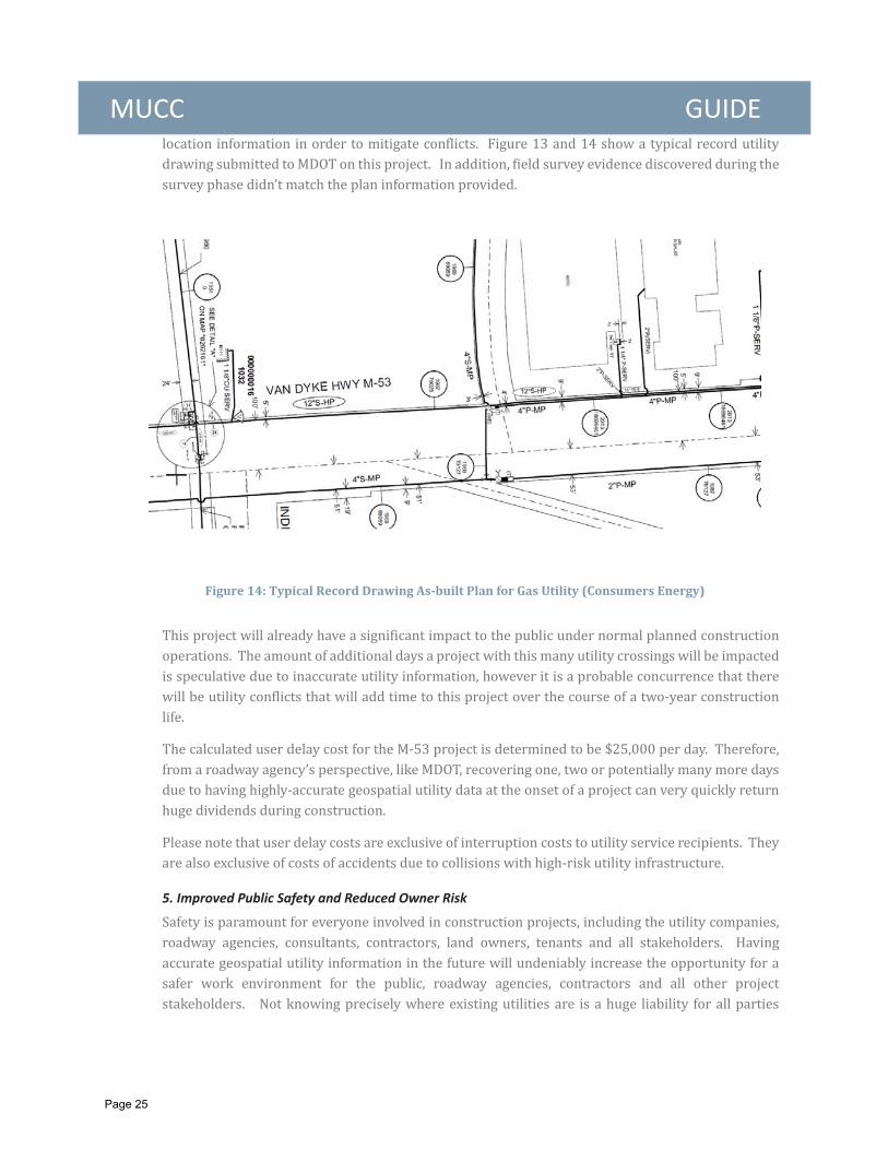
Figure 14: Typical Record Drawing As built Plan for Gas Utility (Consumers Energy)
Page 25
MUCC GUIDE
2.4.3 Data Acquisi on Lessons Learned
1. Data Delivery Standards
Page 26

MUCC GUIDE
2. Coordination of Data Collection
Page 27
MUCC GUIDE
Page 28
MUCC GUIDE
3. Utility Contract Provisions for GUIDE
GUIDE Coordination”,
2.4.4 Concerns
1. Safety
Page 29
MUCC GUIDE
2. Difficulties in Coordination
3. Initial Cost
4. Data Accuracy
Page 30

MUCC GUIDE
5. Uniformity of Standards
6. Data Security & Controlled Access
Page 31

MUCC GUIDE 7. Organizational Change Requirements
2.4.5 Cost Impact Summary
GUIDE Activity Cost Breakdown by Project
CONSUMERS ENERGY
M 21 in Shiawassee County:
Utility Type
Page 32
MUCC GUIDE Primary Installation Method:Estimated Construction Cost:GUIDE Activity Cost:GUIDE Percent of Construction:Cost per linear foot:Cost per data point:Comments:
M 43 Eaton County:
Utility TypePrimary Installation Method:Estimated Construction Cost:GUIDE Activity Cost:GUIDE Percent of Construction:Cost per linear foot:Cost per data point:Comments:
M 20 in Isabella County:
Utility Type:Primary Installation Method:
Page 33
MUCC GUIDE Estimated Construction Cost:GUIDE Activity Cost:GUIDE Percent of Construction:Cost per linear foot:Cost per data point:Comments:
AT&T
M 61 in Gladwin County:Utility Type:Primary Installation Method:Estimated Construction Cost:GUIDE Activity Cost:GUIDE Percent of Construction:Cost per linear foot:Cost per data point:Comments:
M 17 inWashtenaw County:
Primary Installation Method:Estimated Construction CostGUIDE Activity Cost:GUIDE Percent of ConstructionCost per linear foot:Cost per data point:Comments:
Page 34
MUCC GUIDE DTE ENERGY
M 5 (Grand River Avenue) in Wayne County:
Primary Installation Method:Estimated Construction Cost:GUIDE Activity Cost:GUIDE Percent of Construction:Cost per linear foot:Cost per data point:Comments:
M 85 (Fort Street) at Gibraltar Street in Wayne County:
• Primary Installation Method:• Estimated Construction Cost:• GUIDE Activity Cost:• GUIDE Percent of Construction:• Cost per linear foot:• Cost per data point:• Comments:
2.5 OVERALL COST BENEFIT
Cost Savings on Highway Project Utilizing Subsurface Utility Engineering
Evaluating the use of Subsurface Utility Engineeringin Canada
Page 35
MUCC GUIDE
Page 36
MUCC GUIDE 2.5.1 Conclusion
Page 37
MUCC GUIDE
Stage 1 (2015 2016)
Stage 2 (2016 2017
Stage 3 (2017 2018)
Stage 4 (2018 2019)
Stage 5 (2019 2020)
3.1 CONSIDERATIONS FOR THE FUTURE
Page 38
MUCC GUIDE
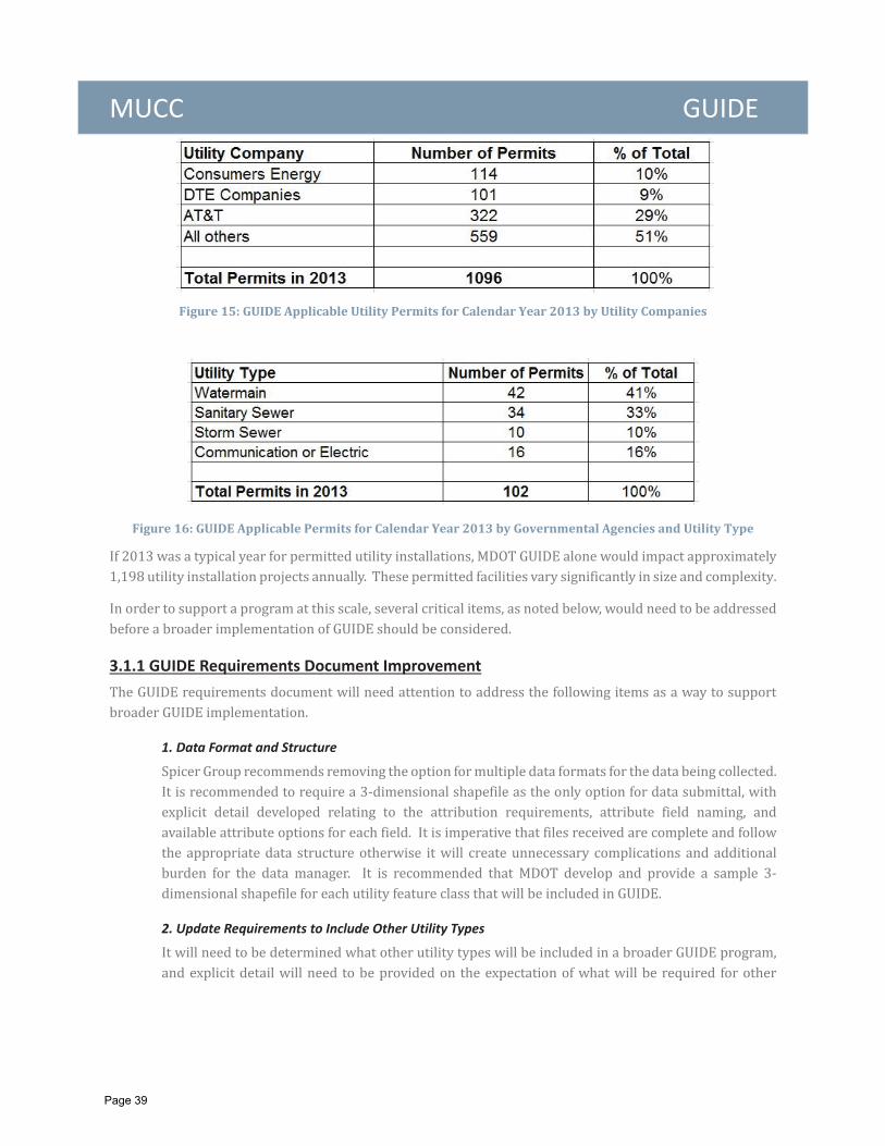
Figure 16: GUIDE Applicable Permits for Calendar Year 2013 by Governmental Agencies and Utility Type
3.1.1 GUIDE Requirements Document Improvement
1. Data Format and Structure
2. Update Requirements to Include Other Utility Types
Figure 15: GUIDE Applicable Utility Permits for Calendar Year 2013 by Utility Companies
Page 39
MUCC GUIDE
3. Update Data Attributing Libraries
3.1.2 Data Management
3.1.3 GUIDE Process Improvement
Page 40
MUCC GUIDE 3.1.4 Intended Use
3.1.5 Accuracy
Page 41
MUCC GUIDE 3.1.6 Safety
3.1.7 Training
3.1.8 Data Security
3.1.9 Statewide Standardiza on
Page 42
MUCC GUIDE
Page 43
MUCC GUIDE
AT&T
Consumer Energy
DTE Energy
Michigan Department of Transportation
MISS DIG Systems Inc.
Michigan Infrastructure and Transportation Association
Page 44
MUCC GUIDE
Evaluating the use of Subsurface Utility Engineering in Canada.
Cost Savings on HighwayProjects Utilizing Surbsurface Utility Engineering.
Page 45
MUCC GUIDE
Page 46
MUCC GUIDE
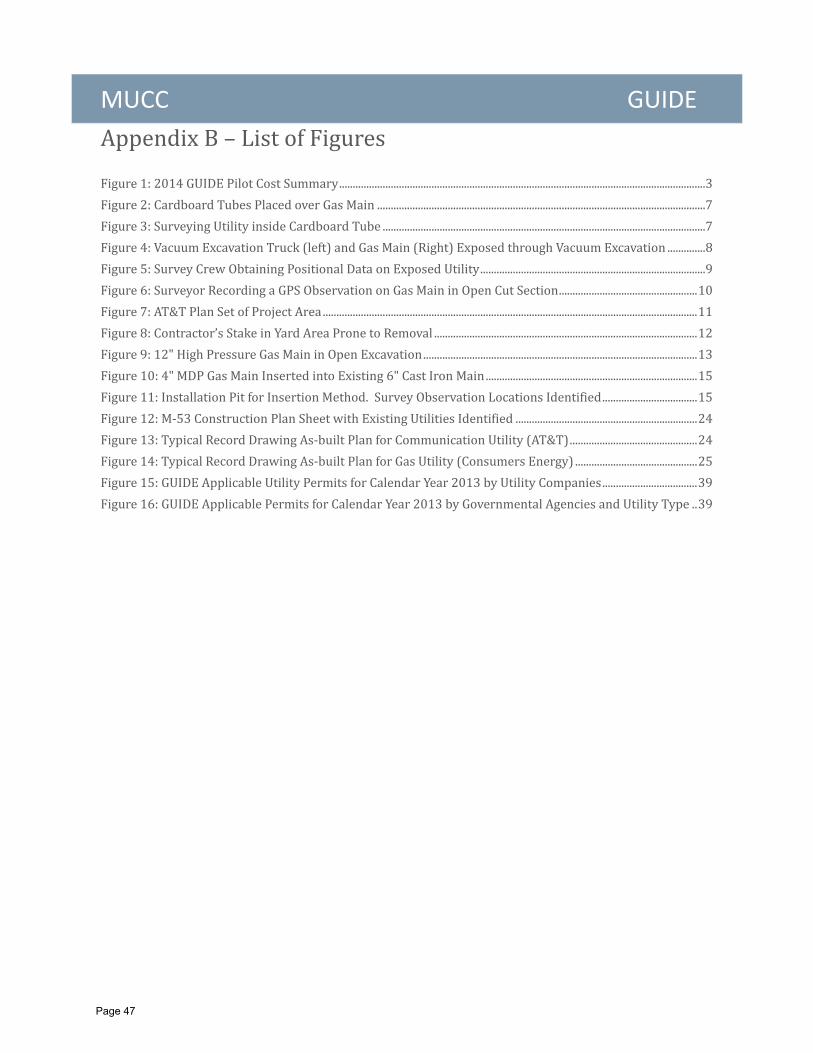
AppendixB–ListofFigures
Figure1:2014GUIDEPilotCostSummary.......................................................................................................................................3Figure2:CardboardTubesPlacedoverGasMain.........................................................................................................................7Figure3:SurveyingUtilityinsideCardboardTube.......................................................................................................................7Figure4:VacuumExcavationTruck(left)andGasMain(Right)ExposedthroughVacuumExcavation..............8Figure5:SurveyCrewObtainingPositionalDataonExposedUtility...................................................................................9Figure6:SurveyorRecordingaGPSObservationonGasMaininOpenCutSection...................................................10Figure7:AT&TPlanSetofProjectArea..........................................................................................................................................11Figure8:Contractor’sStakeinYardAreaPronetoRemoval.................................................................................................12Figure9:12"HighPressureGasMaininOpenExcavation.....................................................................................................13Figure10:4"MDPGasMainInsertedintoExisting6"CastIronMain..............................................................................15Figure11:InstallationPitforInsertionMethod.SurveyObservationLocationsIdentified...................................15Figure12:M‐53ConstructionPlanSheetwithExistingUtilitiesIdentified...................................................................24Figure13:TypicalRecordDrawingAs‐builtPlanforCommunicationUtility(AT&T)...............................................24Figure14:TypicalRecordDrawingAs‐builtPlanforGasUtility(ConsumersEnergy).............................................25Figure15:GUIDEApplicableUtilityPermitsforCalendarYear2013byUtilityCompanies...................................39Figure16:GUIDEApplicablePermitsforCalendarYear2013byGovernmentalAgenciesandUtilityType..39
Page 47

MUCC GUIDE
Page 48
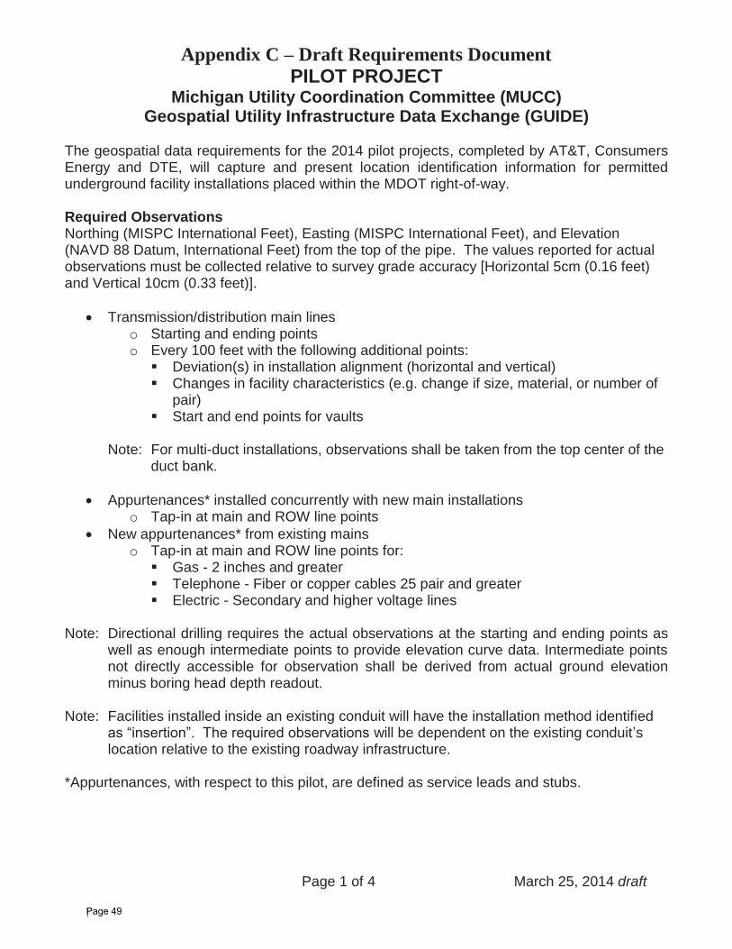
Appendix C – Draft Requirements Document PILOT PROJECT
Michigan Utility Coordination Committee (MUCC) Geospatial Utility Infrastructure Data Exchange (GUIDE)
Page 1 of 4 March 25, 2014 draft
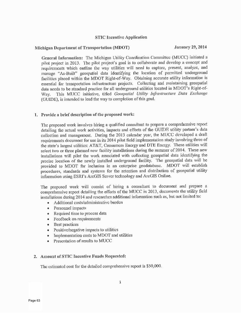
The geospatial data requirements for the 2014 pilot projects, completed by AT&T, Consumers Energy and DTE, will capture and present location identification information for permitted underground facility installations placed within the MDOT right-of-way.
Required Observations Northing (MISPC International Feet), Easting (MISPC International Feet), and Elevation (NAVD 88 Datum, International Feet) from the top of the pipe. The values reported for actual observations must be collected relative to survey grade accuracy [Horizontal 5cm (0.16 feet) and Vertical 10cm (0.33 feet)].
Transmission/distribution main lines o Starting and ending points o Every 100 feet with the following additional points:
Deviation(s) in installation alignment (horizontal and vertical) Changes in facility characteristics (e.g. change if size, material, or number of pair)
Start and end points for vaults
Note: For multi-duct installations, observations shall be taken from the top center of the duct bank.
Appurtenances* installed concurrently with new main installations o Tap-in at main and ROW line points
New appurtenances* from existing mains o Tap-in at main and ROW line points for:
Gas - 2 inches and greater Telephone - Fiber or copper cables 25 pair and greater Electric - Secondary and higher voltage lines
Note: Directional drilling requires the actual observations at the starting and ending points as well as enough intermediate points to provide elevation curve data. Intermediate points not directly accessible for observation shall be derived from actual ground elevation minus boring head depth readout.
Note: Facilities installed inside an existing conduit will have the installation method identified as “insertion”. The required observations will be dependent on the existing conduit’slocation relative to the existing roadway infrastructure.
*Appurtenances, with respect to this pilot, are defined as service leads and stubs.
Page 49
Page 2 of 4 March 25, 2014 draft
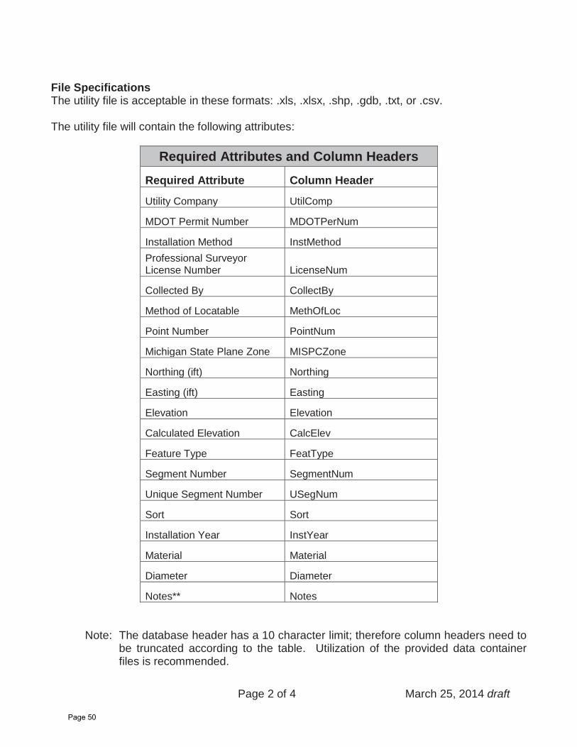
File Specifications The utility file is acceptable in these formats: .xls, .xlsx, .shp, .gdb, .txt, or .csv.
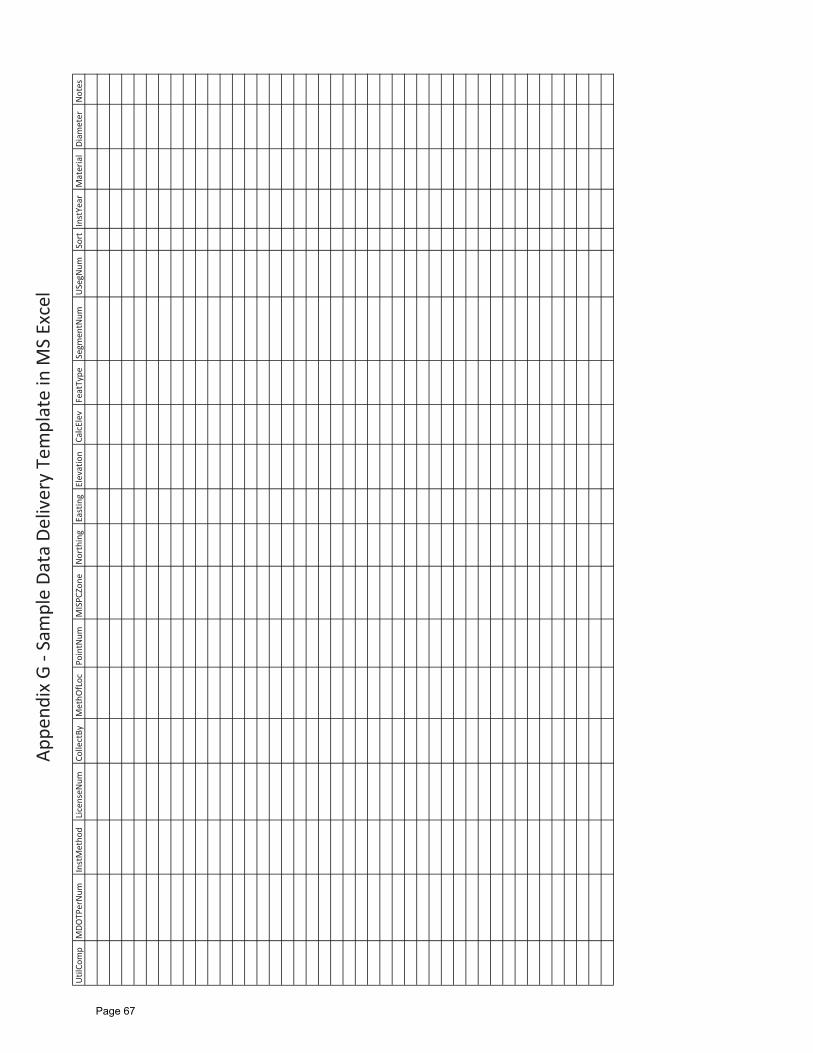
The utility file will contain the following attributes:
Required Attributes and Column Headers
Required Attribute Column Header
Utility Company UtilComp
MDOT Permit Number MDOTPerNum
Installation Method InstMethodProfessional Surveyor License Number LicenseNum
Collected By CollectBy
Method of Locatable MethOfLoc
Point Number PointNum
Michigan State Plane Zone MISPCZone
Northing (ift) Northing
Easting (ift) Easting
Elevation Elevation
Calculated Elevation CalcElev
Feature Type FeatType
Segment Number SegmentNum
Unique Segment Number USegNum
Sort Sort
Installation Year InstYear
Material Material
Diameter Diameter
Notes** Notes
Note: The database header has a 10 character limit; therefore column headers need to be truncated according to the table. Utilization of the provided data container files is recommended.
Page 50
Page 3 of 4 March 25, 2014 draft
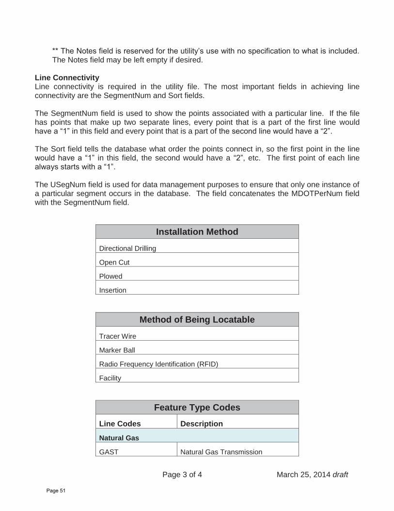
** The Notes field is reserved for the utility’s use with no specification to what is included. The Notes field may be left empty if desired.
Line Connectivity Line connectivity is required in the utility file. The most important fields in achieving line connectivity are the SegmentNum and Sort fields.
The SegmentNum field is used to show the points associated with a particular line. If the file has points that make up two separate lines, every point that is a part of the first line would have a “1” in this field and every point that is a part of the second line would have a “2”.
The Sort field tells the database what order the points connect in, so the first point in the line would have a “1” in this field, the second would have a “2”, etc. The first point of each line always starts with a “1”.
The USegNum field is used for data management purposes to ensure that only one instance of a particular segment occurs in the database. The field concatenates the MDOTPerNum field with the SegmentNum field.
Installation Method
Directional Drilling
Open Cut
Plowed
Insertion
Method of Being Locatable
Tracer Wire
Marker Ball
Radio Frequency Identification (RFID)
Facility
Feature Type Codes
Line Codes Description
Natural Gas
GAST Natural Gas Transmission
Page 51
Page 4 of 4 March 25, 2014 draft
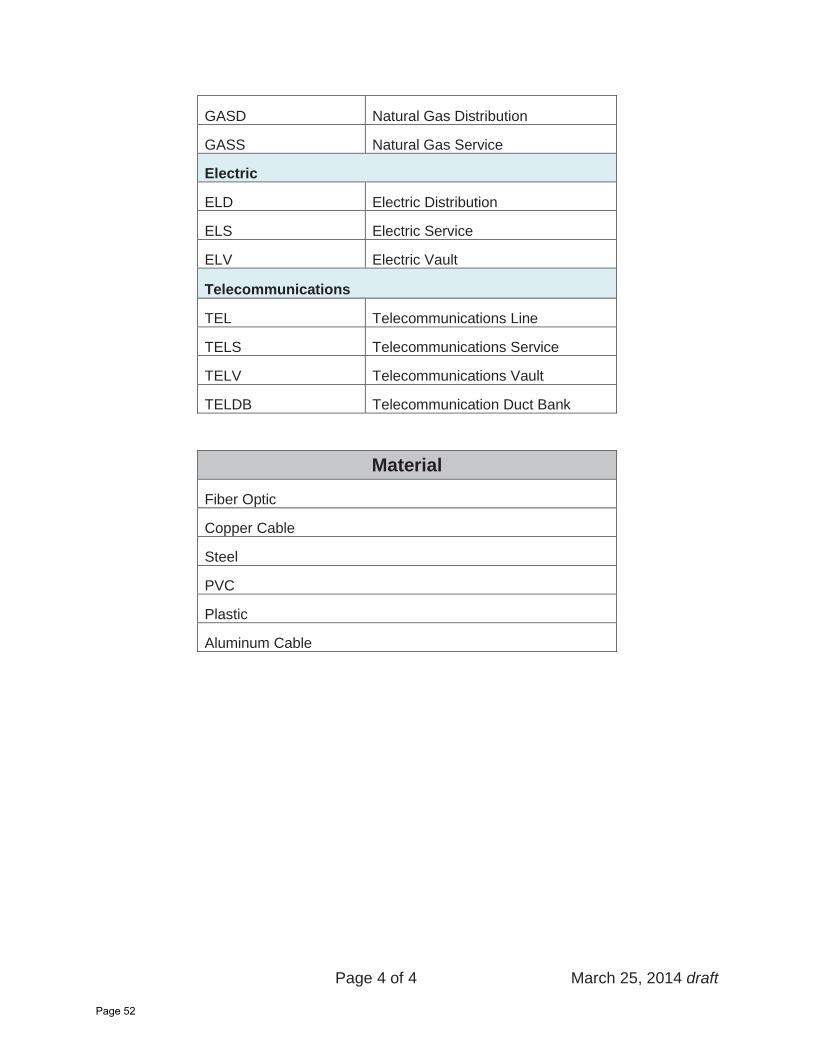
GASD Natural Gas Distribution
GASS Natural Gas Service
Electric
ELD Electric Distribution
ELS Electric Service
ELV Electric Vault
Telecommunications
TEL Telecommunications Line
TELS Telecommunications Service
TELV Telecommunications Vault
TELDB Telecommunication Duct Bank
Material
Fiber Optic
Copper Cable
Steel
PVC
Plastic
Aluminum Cable
Page 52

MUCC GUIDE
Page 53
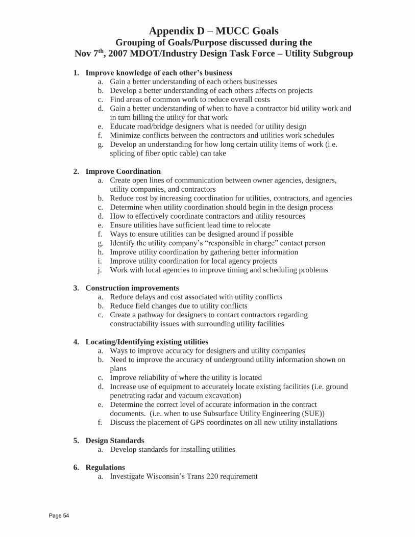
Appendix D – MUCC Goals Grouping of Goals/Purpose discussed during the
Nov 7th, 2007 MDOT/Industry Design Task Force – Utility Subgroup
1. Improve knowledge of each other’s businessa. Gain a better understanding of each others businesses b. Develop a better understanding of each others affects on projects c. Find areas of common work to reduce overall costs d. Gain a better understanding of when to have a contractor bid utility work and
in turn billing the utility for that work e. Educate road/bridge designers what is needed for utility design f. Minimize conflicts between the contractors and utilities work schedules g. Develop an understanding for how long certain utility items of work (i.e.
splicing of fiber optic cable) can take
2. Improve Coordination a. Create open lines of communication between owner agencies, designers,
utility companies, and contractors b. Reduce cost by increasing coordination for utilities, contractors, and agencies c. Determine when utility coordination should begin in the design process d. How to effectively coordinate contractors and utility resources e. Ensure utilities have sufficient lead time to relocate f. Ways to ensure utilities can be designed around if possible g. Identify the utility company’s “responsible in charge” contact personh. Improve utility coordination by gathering better information i. Improve utility coordination for local agency projects j. Work with local agencies to improve timing and scheduling problems
3. Construction improvements a. Reduce delays and cost associated with utility conflicts b. Reduce field changes due to utility conflictsc. Create a pathway for designers to contact contractors regarding
constructability issues with surrounding utility facilities
4. Locating/Identifying existing utilities a. Ways to improve accuracy for designers and utility companies b. Need to improve the accuracy of underground utility information shown on
plansc. Improve reliability of where the utility is located d. Increase use of equipment to accurately locate existing facilities (i.e. ground
penetrating radar and vacuum excavation) e. Determine the correct level of accurate information in the contract
documents. (i.e. when to use Subsurface Utility Engineering (SUE)) f. Discuss the placement of GPS coordinates on all new utility installations
5. Design Standards a. Develop standards for installing utilities
6. Regulations a. Investigate Wisconsin’s Trans 220 requirement
Page 54

MUCC GUIDE
Page 55
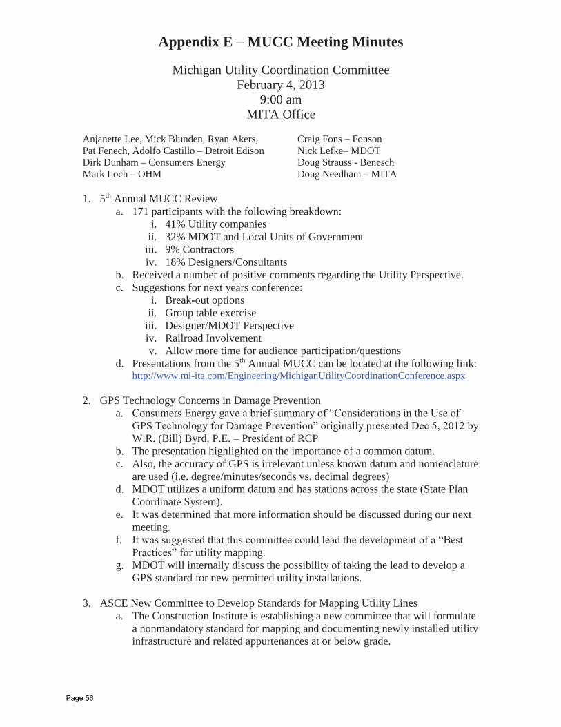
Appendix E – MUCC Meeting Minutes
Michigan Utility Coordination Committee February 4, 2013
9:00 am MITA Office
Anjanette Lee, Mick Blunden, Ryan Akers, Pat Fenech, Adolfo Castillo – Detroit Edison Dirk Dunham – Consumers Energy Mark Loch – OHM
Craig Fons – Fonson Nick Lefke– MDOT Doug Strauss - Benesch Doug Needham – MITA
1. 5th Annual MUCC Review a. 171 participants with the following breakdown:
i. 41% Utility companies ii. 32% MDOT and Local Units of Government
iii. 9% Contractors iv. 18% Designers/Consultants
b. Received a number of positive comments regarding the Utility Perspective. c. Suggestions for next years conference:
i. Break-out options ii. Group table exercise
iii. Designer/MDOT Perspective iv. Railroad Involvement v. Allow more time for audience participation/questions
d. Presentations from the 5th Annual MUCC can be located at the following link: http://www.mi-ita.com/Engineering/MichiganUtilityCoordinationConference.aspx
2. GPS Technology Concerns in Damage Prevention a. Consumers Energy gave a brief summary of “Considerations in the Use of
GPS Technology for Damage Prevention” originally presented Dec 5, 2012 by W.R. (Bill) Byrd, P.E. – President of RCP
b. The presentation highlighted on the importance of a common datum. c. Also, the accuracy of GPS is irrelevant unless known datum and nomenclature
are used (i.e. degree/minutes/seconds vs. decimal degrees) d. MDOT utilizes a uniform datum and has stations across the state (State Plan
Coordinate System). e. It was determined that more information should be discussed during our next
meeting. f. It was suggested that this committee could lead the development of a “Best
Practices” for utility mapping. g. MDOT will internally discuss the possibility of taking the lead to develop a
GPS standard for new permitted utility installations.
3. ASCE New Committee to Develop Standards for Mapping Utility Lines a. The Construction Institute is establishing a new committee that will formulate
a nonmandatory standard for mapping and documenting newly installed utility infrastructure and related appurtenances at or below grade.
Page 56
b. The work of this new committee, the Standards Committee for Utility “As-Built” Data, will complement the ASCE standard 38-02 (Standard Guideline for the Collection and Depiction of Existing Subsurface Utility Data).
c. The MUCC committee has recently developed the “Utility Initial Submittal Requirements” and feels that this would be a good reference document for the newly formed ASCE committee.
d. Brenke will investigate the details and requirements of the proposed committee.
e. It was suggested that a representative from the MUCC participate in this new committee.
4. Expanded Utility Depth Study a. Information about a utility cable and pipe locator (RD 7000+) was distributed
and discussed. The manufacturer states (in good conditions) the depth accuracy is +/-5% for 4” to 10’ for a location using line locating and +/-5 % for 4” to 23’ for locating using Sonde locating.
b. It was mentioned that the 2012 Utility Depth study utilized the RD 8000 locators.
c. After considerable amount of discussion, MDOT mentioned that they were not willing to further the advancement of this study by either placing in an upcoming project or submit for research funding.
d. The utility companies are still concerned with providing an estimated depth even with disclaimers.
e. MITA will continue to discuss with various owner agencies, designers, and utility companies to determine if there is a path for future pilot projects during the 2013 construction season.
5. Light Poles on Bridge Decks a. DTE mentioned MDOT bridge projects, involving railing and/or fencing
installations sometimes prevent access to hand holes as well as complicating light pole inspection. DTE was wondering if there was a standard bridge railing detail that could be modified to allow for continued access to their poles.
b. MDOT mentioned there are numerous bridge railing/fencing details to fit the many types of existing bridges. Modifying these to include all the various types of bridge lighting situations would be challenging.
c. To address current access issues, it was suggested to contact the TSC. To address future projects, it was suggested to discuss during plan review utility coordination meetings.
6. Next Meeting a. The next meeting is scheduled for May 6. 2013 at 9:00am at the MITA
Building.
Page 57
Appendix E – MUCC Meeting Minutes Michigan Utility Coordination Committee
May 6, 2013 9:00 am
MITA Office
Erik Smith, Adolfo Castillo – Detroit Edison Dirk Dunham – Consumers Energy Mark Loch – OHM Craig Fons – Fonson Nick Lefke– MDOT
Al Dionese – AT&T John LaMacchia II – MMLBryan Rewa – Anlaan Bruce Campbell - MISSDIG Doug Needham – MITA
1. DRAFT - Geospatial Data Collection Requirements for Permitted Utility Installations a. A DRAFT version of the “Geospatial Data Collection Requirements for
Permitted Utility Installations Performed within the MDOT ROW” was distributed and discussed.
b. Topics discussed were: i. Elevation verses depth requirements
ii. Desired level of accuracy for x, y and z iii. Reference State Plane Coordinates iv. Applicable to new permitted installations but need a way to capture
existing utilities during construction projects that expose facilities. c. It is anticipated that a final DRAFT document will be developed by November
2013 and be discussed during the 2014 MUCC Conference. d. A subcommittee was formed to further develop the concepts defined in the
DRAFT document. Subcommittee volunteers - MDOT, AT&T, Consumers Energy, Detroit Edison, MISSDIG, and MITA
e. MDOT will coordinate the scheduling of the subcommittee meeting.
2. SHRP 2 Report S2-R15B-RW-1: Identification of Utility Conflicts and Solutions a. The SHRP 2 Report has been discussed in great detail during previous MUCC
meetings. It was reported that the Utility Conflict Matrix is finally published and is currently at the following location http://onlinepubs.trb.org/onlinepubs/shrp2/R15BTrainingMaterials/UtilityConflictMatrix.xls or by following the link contained the final report for SHRP 2 R15-B titled “Identification of Utility Conflicts and Solutions” http://www.trb.org/Main/Blurbs/166731.aspx and clicking on the link titled “training materials”.
b. MDOT distributed the Utility Conflict Matrix to MDOT TSC Utility Coordinators and ACEC for their reference and use. This recently released matrix is an excellent tool that was designed to help State DOTs in their efforts to improve the handling and documentation of utility conflicts.
3. VA DOT/PHMSA Vertical/Horizontal Utility Location Grant a. MISS DIG presented possible grant opportunities to assist with the
development of locatable requirements for various utility facilities along with unique opportunities for pipeline safety matters.
Page 58
b. The PHMSA’s Technical Assistance Grants (TAG) program was discussed in detail. This grant offers new opportunities to strengthen the depth and quality of public participation in pipeline safety matters. TAG program awards enable communities and groups of individuals to obtain funding for technical assistance in the form of engineering or other scientific analysis of pipeline safety issues and helps promote public participation in official proceedings.
c. The deadline for applications for the PHMSA grant is March 2014. It was decided to apply for this grant once the final DRAFT Geospatial Data Collection Requirements for Permitted Utility Installations is completed.
4. ASCE New Committee to Develop Standards for Mapping Utility Lines a. ACEC is continuing to investigate the details and requirements of the
proposed committee. No future details were reported during this meeting.
5. Other a. AT&T is restructuring and will be dedicating an individual to be the one point
of contact for all road construction projects. It is anticipated that this individual will be attending future MUCC meetings.
6. Next Meeting a. MITA will schedule the next meeting in July/August.
Page 59
MUCC GUIDE
Page 60
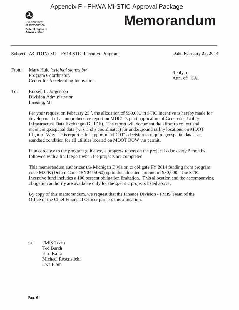
Subject: ACTION: MI – FY14 STIC Incentive Program
From: Mary Huie /original signed by/Program Coordinator, Center for Accelerating Innovation
To: Russell L. Jorgenson Division Administrator
Lansing, MI
Per your request on February 25th, the allocation of $50,000 in STIC Incentive is hereby made for development of a comprehensive report on MDOT’s pilot application of Geospatial Utility Infrastructure Data Exchange (GUIDE). The report will document the effort to collect and maintain geospatial data (w, y and z coordinates) for underground utility locations on MDOT Right-of-Way. This report is in support of MDOT’s decision to require geospatial data as a standard condition for all utilities located on MDOT ROW via permit.
In accordance to the program guidance, a progress report on the project is due every 6 months followed with a final report when the projects are completed.
This memorandum authorizes the Michigan Division to obligate FY 2014 funding from program code M37B (Delphi Code 15X0445060) up to the allocated amount of $50,000. The STIC Incentive fund includes a 100 percent obligation limitation. This allocation and the accompanying obligation authority are available only for the specific projects listed above.
By copy of this memorandum, we request that the Finance Division - FMIS Team of the Office of the Chief Financial Officer process this allocation.
Cc: FMIS TeamTed BurchHari Kalla Michael Rosenstiehl Ewa Flom
Memorandum
Date: February 25, 2014
Reply toAttn. of: CAI
Appendix F - FHWA Mi-STIC Approval Package
Page 61
Page 62
Page 63
Page 64
Page 65
MUCC GUIDE
Page 66
Appe
ndix
G -
Sam
ple
Data
Del
iver
y Te
mpl
ate
in M
S Ex
cel
Util
Com
pM
DOTP
erN
umIn
stM
etho
dLi
cens
eNum
Colle
ctBy
Met
hOfL
ocPo
intN
umM
ISPC
Zone
Nor
thin
gEa
stin
gEl
evat
ion
Calc
Elev
Feat
Type
Segm
entN
umU
SegN
umSo
rtIn
stYe
arM
ater
ial
Diam
eter
Not
es
Page 67