Embed Size (px)
Citation preview

MGE™ Galaxy™3500 Series
10-40 kVA 380/400/415 V10-30 kVA 208/220 V
Operation


Table of Contents
About this Manual .......................................................................................................... 1
Find Updates to this Manual ..................................................................................... 1
Safety .................................................................................................................................... 2
Overview.............................................................................................................................. 3
User Interface ................................................................................................................ 3
Display Interface .......................................................................................................... 4
Menu Tree ........................................................................................................................... 5
Operation ............................................................................................................................ 7
Modes .............................................................................................................................. 7Normal Operation ...................................................................................................... 7Battery Operation ...................................................................................................... 7Internal Bypass Operation ........................................................................................ 7External Maintenance Bypass Operation................................................................... 7Optional Parallel Operation........................................................................................ 7
Single System without External Bypass Panel .................................................... 8Turn into Internal Bypass........................................................................................... 8Turn into Normal Operation ....................................................................................... 9Perform a Total Power Off..........................................................................................10Perform a Restart.......................................................................................................11
Single System with External Bypass Panel ..........................................................12Turn into External Maintenance Bypass ....................................................................12Turn into Normal Operation from External Maintenance Bypass ...............................13Perform a Total Power Off..........................................................................................14Perform a Restart.......................................................................................................14
Parallel System .............................................................................................................15Turn into External Maintenance Bypass ....................................................................15Turn into Normal Operation from External Maintenance Bypass ...............................16Perform a Total Power Off..........................................................................................17Perform a Restart.......................................................................................................17Isolate one UPS in a Parallel System .........................................................................18Turn the Isolated UPS into Normal Operation ............................................................18
Single and Parallel Systems .....................................................................................19Turn Load off/on via the Display Interface .................................................................19Turn Load off – Disconnect the UPS Output to the Load Equipment .........................19Turn Load On – Connect the UPS Output to the Load Equipment .............................20View the Status Screens ............................................................................................20View Logging .............................................................................................................22View Statistics ...........................................................................................................23Use the Diags Screen ................................................................................................24
990–2386D-001 MGE™ Galaxy™3500 Series10-40 kVA 380/400/415 V10-30 kVA 208/220 V i

Configuration ....................................................................................................................25
Settings...........................................................................................................................25Change the Clock, the Alarm Thresholds, and the Dust Filter Status ........................25Clock .........................................................................................................................26Dust Filter ..................................................................................................................27Alarm Thresholds ......................................................................................................28Change the Beeper Setup, the Contrast, and the Language ......................................29
Maintenance ......................................................................................................................30
Parts Replacement ......................................................................................................30Determine if you Need a Replacement Part ...............................................................30Return Parts to APC ..................................................................................................30Remove the Front Panel ............................................................................................31Install the Front Panel................................................................................................32Inspect the Dust Filter ...............................................................................................32Store the Batteries and the UPS System....................................................................34
Battery Module .................................................................................................................36Battery Replacement.........................................................................................................37
Troubleshooting ..............................................................................................................40
Status and Alarm Messages .....................................................................................40Display Messages......................................................................................................40
Dust Filter.......................................................................................................................45
ii MGE™ Galaxy™3500 Series10-40 kVA 380/400/415 V10-30 kVA 208/220 V 990–2386D-001

About this Manual
This manual is intended for the user of the MGE™ Galaxy™3500 series. It refers to important safetywarnings and instructions, gives an introduction to the display interface, and provides information onoperation, load connection, parts replacement, troubleshooting, total power off and restart.
Note: Only graphics of MGE™ Galaxy™ 3500 products with built-in batteries are shown inthis manual, but the manual is intended for users of one or more units within the MGE™Galaxy™3500 series. Most illustrations show 523 mm enclosures but apply to bothenclosure sizes. Any differences between the enclosure sizes will be addressed in the manual.
Find Updates to this ManualYou can check for updates to this manual on www.apc.com. Look for the latest letter revision (A,B etc.) of the manual.
990–2386D-001 MGE™ Galaxy™3500 Series10-40 kVA 380/400/415 V10-30 kVA 208/220 V 1

Safety
WARNING: All safety instructions in the Safety Sheet (990-2940) must be read,understood and followed prior to handling/using the system. Failure to do so couldresult in equipment damage, serious injury, or death.
WARNING: For safety reasons, only qualified personnel is allowed to perform theprocedures described under the chapters “Operation” and “Maintenance” .
Note: Most illustrations show 523 mm enclosures but apply to both enclosure sizes. Anydifferences between the two enclosure sizes will be addressed in the manual.
2 MGE™ Galaxy™3500 Series10-40 kVA 380/400/415 V10-30 kVA 208/220 V 990–2386D-001
Overview
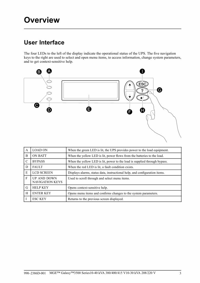
User InterfaceThe four LEDs to the left of the display indicate the operational status of the UPS. The five navigationkeys to the right are used to select and open menu items, to access information, change system parameters,and to get context-sensitive help.
A LOAD ON When the green LED is lit, the UPS provides power to the load equipment.
B ON BATT When the yellow LED is lit, power flows from the batteries to the load.
C BYPASS When the yellow LED is lit, power to the load is supplied through bypass.
D FAULT When the red LED is lit, a fault condition exists.
E LCD SCREEN Displays alarms, status data, instructional help, and configuration items.
F UP AND DOWNNAVIGATION KEYS
Used to scroll through and select menu items.
G HELP KEY Opens context-sensitive help.
H ENTER KEY Opens menu items and confirms changes to the system parameters.
I ESC KEY Returns to the previous screen displayed.
990–2386D-001 MGE™ Galaxy™3500 Series10-40 kVA 380/400/415 V10-30 kVA 208/220 V 3

Display InterfaceThe Overview Screen is the main entrance to the user functions of the display interface. The UP/DOWNnavigation keys take you from one screen to another.
The ENTER key takes you from the Overview Screen to the Main Screen.
From the Main Screen it is possible to command, configure, and monitor the system through the sub menuscreens: Control, Status, Setup, LCM, Logging, Display, Diags, and Help (see “Menu Tree“).Theselector arrow (→) is controlled by the UP/DOWN navigation keys. The arrow marks the item youmay open by pressing ENTER.
Overview Screen
Chrg xxx%Load xxx%xxxVin xxxVout xxHzRuntime: xxhr xxmin
Press
Main Screen
→ Control LoggingStatus DisplaySetup DiagsLCM Help
Press
4 MGE™ Galaxy™3500 Series10-40 kVA 380/400/415 V10-30 kVA 208/220 V 990–2386D-001

Menu Tree
Caution: The display provides access to more functions than described in this manual.Those functions should not be accessed without the assistance of APC Customer Supportin order to avoid unwanted load impacts. For APC by Schneider Electric World-WideCustomer Support, refer to the back cover of this manual. If you by accident go beyond thefunctions described, press ESC to return to previous screens.
990–2386D-001 MGE™ Galaxy™3500 Series10-40 kVA 380/400/415 V10-30 kVA 208/220 V 5

The menu tree provides a quick overview of the functions and views you may access.
Control Turn Load Off/On
UPS into/out of Bypass
Status Vin Vbyp Vout Dust filter
lin lbyp lout Reset dustfilter
kW&kVA
Frequencies Load
Load & Bat & Runtime Shutdown Runtime
Bat AmpHr/ UPS Temp Default Par.redund.
Alarm Thresholds System
Overview Screen Parallel status Alarms
Clock
Other
Setup Settings
Chrg xxx%Load xxx%xVin xVout xHzRuntime: xxhr
LCM Alarms Pending
LCM Contact Info
LCM Alarm Settings
LCM Life Cycle Monitoring
ControlStatusSetupLCM
LoggingDisplayDiagsHelp
Language
Main MenuScreen View Log Contrast
View Statistics Beep.Setup
Logging Logging Menu DisplayFW
Font Pack
Display Display Setup
Int.mech Byp. SW
Diags Faults and Diagnostics Q3 External Byp SW
System Information Status from MBP
Switch Status
Raw Status Data
On any screenand any line, press?
Help
for contextsensitive help
6 MGE™ Galaxy™3500 Series10-40 kVA 380/400/415 V10-30 kVA 208/220 V 990–2386D-001

Operation
WARNING: For safety reasons, only qualified personnel is allowed to perform theoperation procedures described in this chapter.
ModesThe UPS has different operation modes. If the installation includes a Maintenance Bypass Panel (MBP),an external maintenance bypass operation mode will also be available.
Normal Operation
The UPS converts utility/mains power to conditioned power for the connected load.
Battery Operation
The UPS provides power to the connected load from its internal and (if available) external batteries fora finite period. The UPS transfers to battery operation if the supply of utility/mains power fails, or isoutside the pre-defined limits.
Internal Bypass Operation
Internal bypass keeps the load supplied with utility/mains power during maintenance of the UPS powersections. In internal bypass operation, utility/mains power is sent directly to the connected load bypassingall internal UPS functions and filters. Battery back-up is not available in internal bypass operation eventhough the batteries are in place.
External Maintenance Bypass Operation
The UPS can be connected to an optional external MBP. When activated, this panel bypasses the entireUPS enclosure, feeding utility/mains power directly to the load. An activated external MBP completelyisolates the UPS and allows maintenance to be performed. An external MBP is mandatory if the UPSis running in parallel.
Optional Parallel Operation
The connected load is powered by multiple UPS units to increase system redundancy or to increase power.The internal mechanical bypass lever is not available.
990–2386D-001 MGE™ Galaxy™3500 Series10-40 kVA 380/400/415 V10-30 kVA 208/220 V 7

Single System without External Bypass Panel
WARNING: For safety reasons, only qualified personnel is allowed to perform theoperation procedures described in this chapter.
Turn into Internal BypassWARNING: In bypass operation the batteries are still powered. If a total poweroff is required, the load must be off, and the batteries must be pulled out to the reddisconnect line, see the section “Perform a Total Power Off“ in this chapter.
Caution: The load is not protected by the UPS and the power is not conditioned when theinternal mechanical bypass lever is activated.
Note: This procedure is not applicable to parallel systems as the internal mechanical bypasslever is unavailable.
1. If the UPS is running and controllable throughthe display, carry out steps 2-5. If not, godirectly to step 6.
2. From the Overview Screen, press ENTER.
Use Chrg xxx%Load xxx%xxxVin xxxVout xxHzRuntime: xxhr xxmin
Press
3. Go to Control by using the UP/DOWNnavigation keys and press ENTER.
Use → Control LoggingStatus DisplaySetup DiagsLCM Help
Press
4. Go toUPS into Bypass by using theUP/DOWNnavigation keys and press ENTER. Use
→ UPS into BypassDo Self testSimulate Power FailStart Runtime Cal
Press
8 MGE™ Galaxy™3500 Series10-40 kVA 380/400/415 V10-30 kVA 208/220 V 990–2386D-001

5. Go to YES, UPS into Bypass by using theUP/DOWN navigation keys and press ENTER. Use Confirm:
UPS into BypassNO, ABORT
→ YES, UPS into Bypass
Press
6. Check that the UPS is in bypass. The green(LOAD ON) and the yellow (BYPASS) LEDsare illuminated.
WARNING: For safety reasons,only qualified personnel is allowedto perform the following steps.
7. Remove the front panel from the UPS (see“Remove the Front Panel“).
8. Turn the internal mechanical bypass leverupwards to activate it. The load will now besupported directly by utility/mains power.
9. Reinstall the front panel.
Turn into Normal Operation
Caution: Never attempt to switch back the UPS into normal operation till you have verifiedthat there are no internal UPS faults.
1. Check that the UPS is in bypass. The green (LOAD ON) and the yellow (BYPASS) LEDs areilluminated.
2. Turn the mechanical bypass lever downwards into a horizontal position to deactivate the internalbypass operation.
3. If the UPS has not returned to normal operation: Press ESC to return to the previous menus andturn out of bypass from the display via Control > UPS out of bypass > Yes, UPS out of bypass.
4. Check that the UPS is in normal operation. The yellow (BYPASS) LED turns off and the green(LOAD ON) LED remains illuminated.
990–2386D-001 MGE™ Galaxy™3500 Series10-40 kVA 380/400/415 V10-30 kVA 208/220 V 9

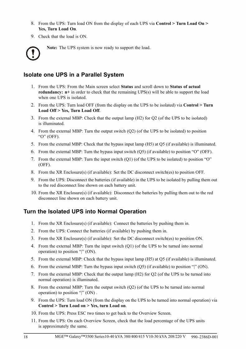
Perform a Total Power Off
Note: In order to carry out this procedure the load supported by the UPS must be turned off.
10/100Base- TProbe
AP9619 Network Management Card EM
Reset
Output Pwr Zone
10/100
ON
OFF
3
4
5
6
AB
B C
A Mains breaker
B UPS
C XR Enclosure
1. Check that the load which is supported by the UPS is turned OFF.
2. From the UPS: Turn load OFF from the display via Control > Turn Load Off > Yes, TurnLoad Off.
3. From the XR Enclosure(s) (if available): Set the DC disconnect switch(es) to position OFF.
4. From the UPS: Disconnect the batteries (if available) by pulling them out to the red disconnectline shown on each battery unit.
5. From the XR Enclosure(s) (if available): Disconnect the batteries by pulling them out to the reddisconnect line shown on each battery unit.
6. Set the utility/mains breaker to position OFF or LOCKED-OUT. If the UPS has dual utility/mainssupply, set both supplies to position OFF or LOCKED-OUT.
WARNING: The lockout procedures at the utility/mains breaker must be followed.If necessary, install a padlock.
Note: For details on how to remove Battery Locks (if available) (see the section “Replace aBattery Module“ and hereunder “Remove and Install Battery Locks“).
10 MGE™ Galaxy™3500 Series10-40 kVA 380/400/415 V10-30 kVA 208/220 V 990–2386D-001

Perform a RestartWARNING: Only qualified personnel familiar with the construction and the equipmentmay restart the UPS.
1. Set the utility/mains breaker to position ON. 2. If your installation includes an XR BatteryEnclosure with a DC disconnect switch, set theDC disconnect switch to position ON.
Note: Wait approximately 30seconds for the system to boot upand carry out a self test.
After system boot-up, the display will automaticallyask you to confirm/select voltage and frequency asshown in the following.
Voltage confirmation. At restart, the display willprompt you through the following screens:
3.When the Confirm Voltage prompt appears onthe screen, go to the desired voltage using theUP/DOWN navigation keys and press ENTER.
Use Confirm VoltageUse 400V
→ Yes, use 400VNo, select another
Press
4.When the prompt Apply load appears, go toYes using the UP/DOWN navigation keys andpress ENTER if you want the UPS to provide aload output now. (If you do not want a UPS loadoutput at this point, go to No).
UseApply load
→ YesNo
Press
5. The green (LOAD ON) LED is now lit. PressESC two times and the display will return to theOverview Screen.
Use Chrg xxx%Load xxx%xxxVin xxxVout xxHzRuntime: xxhr xxmin
Press
Note: The UPS is now ready to support the load.
990–2386D-001 MGE™ Galaxy™3500 Series10-40 kVA 380/400/415 V10-30 kVA 208/220 V 11

Note:
The auto-detection on frequency has been improved in firmware version 5.1 and higher forsingle units (with parallel capability). Auto-detection on frequency is an option in the Setupmenu (in alignment with the values 50Hz and 60Hz) but also a feature whereby a single UPSsystem detects the input frequency in a system start-up.
If the UPS system during a start-up detects an input frequency different from what is alreadyset, then the user will be asked to choose the detected frequency. The system will not changefrequency by itself. For safety reasons, the input frequency can only be changed by the user.The auto-detection on frequency-feature is only applicable in a single system start-up. If aproblem occurs call APC Customer Support (see the back cover of this manual).
Single System with External Bypass Panel
WARNING: For safety reasons, only qualified personnel is allowed to perform theoperation procedures described in this chapter.
Turn into External Maintenance BypassWARNING: In bypass operation the batteries are still powered. If a total poweroff is required, the load must be off, and the batteries must be pulled out to the reddisconnect line (see “Perform a Total Power Off“ in this chapter).
1. From the Overview Screen, press ENTER.
Use Chrg xxx%Load xxx%xxxVin xxxVout xxHzRuntime: xxhr xxmin
Press
2. Go to Control by using the UP/DOWNnavigation keys and press ENTER. Use → Control Logging
Status DisplaySetup DiagsLCM Help
Press
3. Go toUPS into Bypass by using theUP/DOWNnavigation keys and press ENTER. Use → UPS into Bypass
Do Self testSimulate Power FailStart Runtime Cal
Press
12 MGE™ Galaxy™3500 Series10-40 kVA 380/400/415 V10-30 kVA 208/220 V 990–2386D-001

4. Go to Yes, UPS into Bypass by using theUP/DOWN navigation keys and press ENTER.
Use Confirm:UPS into BypassNO, ABORT
→ YES, UPS into Bypass
Press
5. From the external Maintenance Bypass Panel(MBP): Turn the bypass switch (Q3) to position“|” (ON).
6. From the external MBP: Turn the output switch(Q2) to position “O” (OFF). Now the load is notsupported by the UPS.
Note: Note! If you need to turn theUPS completely OFF, proceed withsteps 7–11.
7. If you need to turn the UPS completely OFF:From the external MBP: Turn the input switch(Q1) to position “O” (OFF).
8. From the XR Enclosure(s) (if available): Set theDC disconnect switch(es) to position OFF.
9. From the UPS: Disconnect the batteries (ifavailable) by pulling them out to the reddisconnect line shown on each battery unit.
10.From the XR Enclosure(s) (if available):Disconnect the batteries by pulling them out tothe red disconnect line shown on each batteryunit.
Turn into Normal Operation from External Maintenance Bypass
Caution: Never attempt to switch back the UPS into normal operation till you have verifiedthat there are no internal UPS faults.
1. If the UPS has been completely turned OFF, proceed with steps 2–10. If the UPS has not beencompletely turned OFF, proceed with steps 6–10.
2. From the XR Enclosure(s) (if available): Connect the batteries by pushing them in.
3. From the UPS: Connect the batteries (if available) by pushing them in.
4. From the XR Enclosure(s) (if available): Set the DC disconnect switch(es) to position ON.
5. From the XR Enclosure(s) (if available): Set the DC disconnect switch(es) to position ON.
6. From the external MBP: Turn the output switch (Q2) to position “|” (ON). Now the load issupported by the UPS.
7. From the UPS: Check that the yellow (BYPASS) LED is illuminated and the green (LOAD ON)LED is illuminated.
8. From the external MBP: Turn the bypass switch (Q3) to position “O” (OFF).
9. If the UPS has not returned to normal: From the UPS: Turn out of bypass from the display viaControl > UPS out of bypass > Yes, UPS out of bypass.
10. From the UPS: Check that the UPS is in normal operation. The yellow (BYPASS) LED turns offand the green (LOAD ON) LED remains illuminated.
990–2386D-001 MGE™ Galaxy™3500 Series10-40 kVA 380/400/415 V10-30 kVA 208/220 V 13

Perform a Total Power Off
Note: In order to carry out this procedure the load supported by the UPS must be turned off.
1. Check that the load which is supported by the UPS is turned OFF.
2. From the UPS: Turn load OFF from the display via Control > Turn Load Off > Yes, TurnLoad Off.
3. From the external MBP: Turn the output switch (Q2) to position “O” (OFF).
4. From the external MBP: Turn the input switch (Q1) to position “O” (OFF).
5. From the XR Enclosure(s) (if available): Set the DC disconnect switch to position OFF.
6. From the UPS: Disconnect the batteries (if available) by pulling them out to the red disconnectline shown on each battery unit.
7. From the XR Enclosure(s) (if available): Disconnect the batteries by pulling them out to the reddisconnect line shown on each battery unit.
Perform a Restart
Note: Only qualified personnel familiar with the construction and the equipment may restartthe UPS.
1. From the XR Enclosure(s) (if available): Connect the batteries by pushing them in.
2. From the UPS: Connect the batteries (if available) by pushing them in.
3. From the XR Enclosure(s) (if available): Set the DC disconnect switch(es) to position ON.
4. From the external MBP: Turn the input switch (Q1) to position “|” (ON).
5. From the external MBP: Turn the output switch (Q2) to position “|” (ON).
6. From the UPS: Turn load ON from the display via Control > Turn Load On > Yes, TurnLoad On.
7. Check that the load is ON.
Note: The UPS is now ready to support the load.
Note: The auto-detection on frequency has been improved in firmware version 5.1 andhigher for single units (with parallel capability). Auto-detection on frequency is an option inthe Setup menu (in alignment with the values 50Hz and 60Hz) but also a feature whereby asingle UPS system detects the input frequency in a system start-up.
If the UPS system during a start-up detects an input frequency different from what is alreadyset, then the user will be asked to choose the detected frequency. The system will not changefrequency by itself. For safety reasons, the input frequency can only be changed by the user.The auto-detection on frequency-feature is only applicable in a single system start-up. If aproblem occurs call APC Customer Support (see the back cover of this manual).
14 MGE™ Galaxy™3500 Series10-40 kVA 380/400/415 V10-30 kVA 208/220 V 990–2386D-001

Parallel System
WARNING: For safety reasons, only qualified personnel is allowed to perform theoperation procedures described in this chapter.
WARNING: Parallel Operation is not available when the system is set up for 3–wireoperation, which only applies to Japanese systems.
Turn into External Maintenance BypassWARNING: In bypass operation the batteries are still charged. If a total power off isrequired, the load must be off and the batteries must be pulled out to the red disconnectline (see “Perform a Total Power Off“ in this chapter).
1. From the Overview Screen, press ENTER.
Use Chrg xxx%Load xxx%xxxVin xxxVout xxHzRuntime: xxhr xxmin
Press
2. Go to Control by using the UP/DOWNnavigation keys and press ENTER. Use → Control Logging
Status DisplaySetup DiagsLCM Help
Press
3. Go toUPS into Bypass by using theUP/DOWNnavigation keys and press ENTER. Use → UPS into Bypass
Do Self testSimulate Power FailStart Runtime Cal
Press
4. Go to YES, UPS into Bypass by using theUP/DOWN navigation keys and press ENTER. Use Confirm:
UPS into BypassNO, ABORT
→ YES, UPS into Bypass
Press
5. From the UPS: Check that all UPS units arein bypass on each of the displays. The yellowbypass LED is illuminated on each UPS unit.
6. From the external Maintenance Bypass Panel(MBP): Check that the bypass lamp indicator(H3) is illuminated at Q3.
990–2386D-001 MGE™ Galaxy™3500 Series10-40 kVA 380/400/415 V10-30 kVA 208/220 V 15

7. From the external MBP: Turn the bypass switch(Q3) to position “|” (ON).
8. From the external MBP: Check that the lampindicator of the output isolation breaker (H4) atQ4 is illuminated.
9. From the external MBP: Turn the outputisolation breaker (Q4) to position “O” (OFF).The UPS is now in external maintenance bypasswith the batteries still powered. Note! If youneed to turn the UPS units completely OFF,proceed with steps 11–18.
Note: Note! If you need to turn theUPS units completely OFF, proceedwith steps 11–18.
10.From the UPS: Turn OFF each UPS unit fromthe display via Control > Turn Load Off > Yes,Turn Load Off.
11.From the external MBP: Check that all theoutput lamps (H2a, H2b, H2c) for Q2 areilluminated.
12.From the external MBP: Turn all outputswitches (Q2) to position “O” (OFF).
13.From the external MBP: Turn all input switches(Q5) (if available) to position “O” (OFF).
14.From the external MBP: Turn all input switches(Q1) to position “O” (OFF).
15.From the XR Enclosure(s) (if available): Setthe DC disconnect switch(es) to position OFF.
16.From the UPS: Disconnect the batteries (ifavailable) by pulling them out to the reddisconnect line shown on each battery unit.
17.From the XR Enclosure(s) (if available):Disconnect the batteries by pulling them out tothe red disconnect line shown on each batteryunit.
18.De-energize all UPS inputs.
Turn into Normal Operation from External Maintenance Bypass
Caution: Never attempt to turn the UPS into normal operation till you have verified thatthere are no internal UPS faults.
1. If the UPS units have been completely turned OFF, proceed with steps 2–16. If the UPS unitshave not been completely turned OFF, proceed with step 13–16.
2. From the UPS: Connect the batteries (if available) in each UPS by pushing them in.
3. From the XR Enclosure(s) (if available): Connect the batteries in each UPS by pushing them in.
4. From the XR Enclosure(s) (if available): Set the DC disconnect switch(es) to position ON.
5. From the external MBP: Turn all input switches (Q1) to position “|” (ON).
6. From the external MBP: Check that all the bypass input lamps (H5) at Q5 (if available) areilluminated.
7. From the external MBP: Turn all bypass input switches (Q5) (if available) to position “|” (ON).
8. From the external MBP: Check that all the output lamps (H2) for Q2 are illuminated.
9. From the external MBP: Turn all output switches (Q2) to position “|” (ON). The lamp indicator ofthe output isolation breaker (Q4) is still illuminated.
10. From the UPS: Turn ON all UPS units from each display via Control > Turn Load ON > Yes,Turn Load ON. The green online LEDs are illuminated on each UPS unit.
16 MGE™ Galaxy™3500 Series10-40 kVA 380/400/415 V10-30 kVA 208/220 V 990–2386D-001

11. From the external MBP: Check that all the output lamps (H2) for Q2 are not illuminated and thatall the bypass input lamps (H5) at Q5 (if available) are not illuminated.
12. From the UPS: Turn the UPS units into bypass from one UPS display via Control > UPS intobypass > Yes, UPS into bypass. Check that the UPS units are in bypass. The green (LOAD ON)and the yellow (BYPASS) LEDs are illuminated.
13. From the external MBP: Check that the lamp indicator of the output isolation breaker (Q4)is illuminated.
14. From the external MBP: Turn the output isolation breaker (Q4) to position “|” (ON). Now thelamps H3 + H4 are illuminated.
15. From the external MBP: Turn the bypass switch (Q3) to position “O” (OFF). The lamp indicatorof the output isolation breaker (H4) for Q4 is not illuminated, but the bypass lamp (H3) for Q3is illuminated, until the UPS is running in normal operation.
16. From the UPS: Turn the UPS units out of bypass from the display via Control > UPS out ofbypass > Yes, UPS out of bypass.
Perform a Total Power Off
Note: In order to carry out this procedure the load supported by the UPS must be turned off.
1. Check that the load which is supported by the UPS is turned OFF.2. From the UPS: Turn load OFF from each of the UPS displays via Control > Turn Load Off >
Yes, Turn Load Off.3. From the external MBP: Turn the output isolation breaker (Q4) to position “O” (OFF).4. From the external MBP: Turn all output switches (Q2) to position “O” (OFF).5. From the external MBP: Turn all input switches (Q1) to position “O” (OFF)6. From the XR Enclosure(s) (if available): Set the DC disconnect switch(es) to position OFF.7. From the external MBP: Turn all bypass input switches (Q5) (if available) to position “O” (OFF).8. From the UPS: Disconnect the batteries in the UPS units by pulling them out to the red disconnect
line shown on beach battery unit.9. From the XR Enclosure(s) (if available): Disconnect the batteries on the UPS units by pulling
them out to the red disconnect line shown on each battery unit.10. De-energize all UPS inputs.
Perform a RestartWARNING: Only qualified personnel familiar with the construction and the equipmentmay restart the UPS system.
1. From the XR Enclosure(s) (if available): Connect the batteries by pushing them in.2. From the UPS: Connect the batteries (if available) by pushing them in.3. From the XR Enclosure(s) (if available): Set the DC disconnect switch(es) to position ON.4. From the external MBP: Turn all input switches (Q1) to position “| (ON).5. From the external MBP: Turn all bypass input switches (Q5) (if available) to position “|” (ON).6. From the external MBP: Turn all output switches (Q2) to position “|” (ON).7. From the external MBP: Turn the output isolation breaker (Q4) to position “|” (ON).
990–2386D-001 MGE™ Galaxy™3500 Series10-40 kVA 380/400/415 V10-30 kVA 208/220 V 17
8. From the UPS: Turn load ON from the display of each UPS via Control > Turn Load On >Yes, Turn Load On.
9. Check that the load is ON.
Note: The UPS system is now ready to support the load.
Isolate one UPS in a Parallel System
1. From the UPS: From the Main screen select Status and scroll down to Status of actualredundancy: n+ in order to check that the remaining UPS(s) will be able to support the loadwhen one UPS is isolated.
2. From the UPS: Turn load OFF (from the display on the UPS to be isolated) via Control > TurnLoad Off > Yes, Turn Load Off.
3. From the external MBP: Check that the output lamp (H2) for Q2 (of the UPS to be isolated)is illuminated.
4. From the external MBP: Turn the output switch (Q2) (of the UPS to be isolated) to position“O” (OFF).
5. From the external MBP: Check that the bypass input lamp (H5) at Q5 (if available) is illuminated.
6. From the external MBP: Turn the bypass input switch (Q5) (if available) to position “O” (OFF).
7. From the external MBP: Turn the input switch (Q1) (of the UPS to be isolated) to position “O”(OFF).
8. From the XR Enclosure(s) (if available): Set the DC disconnect switch(es) to position OFF.
9. From the UPS: Disconnect the batteries (if available) in the UPS to be isolated by pulling them outto the red disconnect line shown on each battery unit.
10. From the XR Enclosure(s) (if available): Disconnect the batteries by pulling them out to the reddisconnect line shown on each battery unit.
Turn the Isolated UPS into Normal Operation
1. From the XR Enclosure(s) (if available): Connect the batteries by pushing them in.
2. From the UPS: Connect the batteries (if available) by pushing them in.
3. From the XR Enclosure(s) (if available): Set the DC disconnect switch(es) to position ON.
4. From the external MBP: Turn the input switch (Q1) (of the UPS to be turned into normaloperation) to position “|” (ON).
5. From the external MBP: Check that the bypass input lamp (H5) at Q5 (if available) is illuminated.
6. From the external MBP: Turn the bypass input switch (Q5) (if available) to position “|” (ON).
7. From the external MBP: Check that the output lamp (H2) for Q2 (of the UPS to be turned intonormal operation) is illuminated.
8. From the external MBP: Turn the output switch (Q2) (of the UPS to be turned into normaloperation) to position “|” (ON) .
9. From the UPS: Turn load ON (from the display on the UPS to be turned into normal operation) viaControl > Turn Load on > Yes, turn Load on.
10. From the UPS: Press ESC two times to get back to the Overview Screen.
11. From the UPS: On each Overview Screen, check that the load percentage of the UPS unitsis approximately the same.
18 MGE™ Galaxy™3500 Series10-40 kVA 380/400/415 V10-30 kVA 208/220 V 990–2386D-001

Single and Parallel Systems
Turn Load off/on via the Display InterfaceWARNING: Warning: Disconnecting the UPS output to the load does NOT de-energizethe UPS! Always follow the total power off procedure in the respective chapters if youneed to de-energize the UPS in emergency situations.
Turn Load off – Disconnect the UPS Output to the Load Equipment
1. From the Overview Screen, press ENTER.
UseChrg xxx%Load xxx%xxxVin xxxVout xxHzRuntime: xxhr xxmin
Press
2. Go to Control by using the UP/DOWNnavigation keys and press ENTER. Use
→ Control LoggingStatus DisplaySetup DiagsLCM Help
Press
3. Go to Turn Load OFF by using the UP/DOWNnavigation keys and press ENTER. Use → Turn Load Off Press
4. Go to YES, Turn Load OFF by using theUP/DOWN navigation keys and press ENTER. Use Confirm:
Turn Load OFFNO, ABORT
→ YES, Turn Load OFF
Press
5. If the UPS is running in parallel operation thisprocedure must be carried out on each UPS.
990–2386D-001 MGE™ Galaxy™3500 Series10-40 kVA 380/400/415 V10-30 kVA 208/220 V 19

Turn Load On – Connect the UPS Output to the Load Equipment
1. From the Overview Screen, press ENTER.
Chrg xxx%Load xxx%xxxVin xxxVout xxHzRuntime: xxhr xxmin
Press
2. Go to Control by using the UP/DOWNnavigation keys and press ENTER. Use → Control Logging
Status DisplaySetup DiagsLCM Help
Press
3. Go to Turn Load ON by using the UP/DOWNnavigation keys and press ENTER. Use → Turn Load On Press
4. Go to Yes, Turn Load ON by using theUP/DOWN navigation keys and press ENTER.
Use Confirm:Turn Load OFFNO, ABORT
→ YES, Turn Load ON
Press
View the Status Screens
1. From the Overview Screen, press ENTER.
UseChrg xxx%Load xxx%xxxVin xxxVout xxHzRuntime: xxhr xxmin
Press
2. Go to Status by using the UP/DOWNnavigation keys and press ENTER. Use Control Logging
→ Status DisplaySetup DiagsLCM Help
Press
3. Use the UP/DOWN keys to go through thebelow parameters and press the ESC key toreturn to the previous menus.
20 MGE™ Galaxy™3500 Series10-40 kVA 380/400/415 V10-30 kVA 208/220 V 990–2386D-001

View Parameters
Voltage on all phases Utility/mains voltage (V), bypass voltage (V), andoutput voltage (V) for each phase.
Current on all phases Utility/mains current (A), bypass current (A), and outputcurrent (A) for each phase.
kVA and kW Apparent power (kVA) and real power (kW) generatedby the UPS and the connected load.
Frequencies Utility/mains frequency, bypass frequency, and outputfrequency in Hertz (Hz).
Load and batteries Load: Percentage of the load in relation to the total UPScapacity.
Bat Voltage Shows either the positive or negative half of the batteryvoltage (the lower value of the two will appear).
Bat Cap Percentage charge on the batteries in relation to the totalbattery capacity.Runtime: The predicted runtime at the present load.
Batteries Bat AmpHr: Battery capacity, including both externaland internal batteries. UPS Temp: The highest externalbattery temperature.
Alarm thresholds Load: An alarm will be set when the load is above thethreshold level.Runtime: An alarm will be set when the runtime isbelow the threshold level.
Parallel Status Local UPS is slave/master:# of UPSs OK: Indicates the number of parallel UPSunits that is OK# of UPSs fail: Indicates the number of parallel UPSthat has failed.
Par load Status KVA and KW: Total apparent power (kVA) and realpower (kW) generated by the parallel UPS units and theconnected load.Par redundancy: n+1, an alarm will be set if theredundancy level is below the threshold level.
Parallel Operation Mode The parallel operation mode can be off, load on,requested bypass, in bypass due to fault or maintenance.
990–2386D-001 MGE™ Galaxy™3500 Series10-40 kVA 380/400/415 V10-30 kVA 208/220 V 21

View Logging
View the 100 most recent UPS log events, and view the logged details of the events, such as date, time ofoccurrence, and event number.
1. From the Overview Screen, press ENTER.
Chrg xxx%Load xxx%xxxVin xxxVout xxHzRuntime: xxhr xxmin
Press
2. Go to Logging by using the UP/DOWNnavigation keys and press ENTER. Use
Control → LoggingStatus DisplaySetup DiagsLCM Help
Press
3. Go to View Log by using the UP/DOWNnavigation keys and press ENTER. Use
→ View logClear logView statistics
Press
4. Go to On Line by using the UP/DOWNnavigation keys and press ENTER. Use
24-Sep 15:06:48 #15Mains out of Range
→ On Line
Press
Logging Screen (example)
5. The top line states date, time, and event number.Lines 2, 3, and 4 are part of the event list. Toview the entire list: Use the UP/DOWN keys togo through the log events and press ENTER toget a detailed description of a particular event.
22 MGE™ Galaxy™3500 Series10-40 kVA 380/400/415 V10-30 kVA 208/220 V 990–2386D-001

View Statistics
View the statistics on the operation mode changes, the inverter time, and the duration of battery operation.
1. From the Overview Screen, press ENTER.
Chrg xxx%Load xxx%xxxVin xxxVout xxHzRuntime: xxhr xxmin
Press
2. Go to Logging by using the UP/DOWNnavigation keys and press ENTER. Use
Control → LoggingStatus DisplaySetup DiagsLCM Help
Press
3. Go to View Statistics by using the UP/DOWNnavigation keys and press ENTER.
Use
View logClear log
→ View statistics
Press
990–2386D-001 MGE™ Galaxy™3500 Series10-40 kVA 380/400/415 V10-30 kVA 208/220 V 23

Use the Diags Screen
View troubleshooting information
1. From the Overview Screen, press ENTER.
Chrg xxx%Load xxx%xxxVin xxxVout xxHzRuntime: xxhr xxmin
Press
2. Go to Diags by using the UP/DOWN navigationkeys and press ENTER. Use Control Logging
Status DisplaySetup → DiagsLCM Help
Press
3. Go to Fault & Diagnostics by using theUP/DOWN navigation keys and press ENTER. Use → Fault & Diagnostics
System InformationSwitch statusRaw Status Data
Press
Note: For more details on the Fault and Diagnostics screens, see the section“Troubleshooting“.
24 MGE™ Galaxy™3500 Series10-40 kVA 380/400/415 V10-30 kVA 208/220 V 990–2386D-001

Configuration
Settings
Change the Clock, the Alarm Thresholds, and the Dust Filter Status
Dust filter
Reset dust filter
Load
Shutdown Runtime
Default Par. redund.
SystemOverviewScreen Alarms
Clock
Other
Setup Settings
Chrg xxx%Load xxx%xxx Vin xxx VoutxxHzRuntime xxhr
ControlStatusSetupLCM
LoggingDisplayDiagsHelp
Main Menu Screen
990–2386D-001 MGE™ Galaxy™3500 Series10-40 kVA 380/400/415 V10-30 kVA 208/220 V 25

Clock
The Clock menu changes the date and the clock settings and it time-stamps events in the event log. Toavoid inaccuracies, change the clock-setting at daylight-saving time.
1. From the Overview Screen, press ENTER.
Chrg xxx%Load xxx%xxxVin xxxVout xxHzRuntime: xxhr xxmin
Press
2. Go to Setup by using theUP/DOWN navigationkeys and press ENTER. Use Control Logging
Status Display→ Setup DiagsLCM Help
Press
3. Go toClock by using theUP/DOWN navigationkeys and press ENTER. Use Settings:
Shutdown AlarmsDefault → ClockSystem Other
Press
4. Press ENTER.
→ Date: 24-Sep-2010Time: 13:45:51
Press
5. The day is now active. Use the UP/DOWNnavigation keys to set the date and pressENTER.
Use
→ Date: 24-Sep-2010Time: 13:28:00
Press
6. The month is now active. Use the UP/DOWNnavigation keys to set the month, press ENTERand do the same to set the year, and pressENTER.
Use
→ Date: 24-Sep-2010Time: 13:28:00
Press
26 MGE™ Galaxy™3500 Series10-40 kVA 380/400/415 V10-30 kVA 208/220 V 990–2386D-001

7. Press the DOWN navigation key to activate theTime line. Use
Date: 24-Sep-2010→ Time: 13:28:00
Press
8. The procedure to change the Time features isthe same as described for date, month, and year. Press
Dust Filter
Note: When a dust filter is installed for the first time or when a UPS is installed with factorypre-installed dust filter, then the dust filter surveillance should be enabled. The parametersare High,Medium, or Low. A High parameter selection is for heavy dust environmentsand will prompt the user to replace the dust filter after 90 days. AMedium parameterselection will prompt the user to replace the dust filter after 120 days and a Low parameterselection will prompt the user to replace the dust filter after 150 days. A pre-warning willappear five days before the filter must be replaced. If a filter needs replacement, (when theexisting filter is filled with dust and an alarm has been initiated) then you must replace thefilter and make sure that the Reset dust filter setting is set to Yes. Firmware upgrade orenabling the dust filter surveillance is not applicable for UPS models which do not have thecapability of running in parallel.
1. From the Overview Screen, press ENTER.
Chrg xxx%Load xxx%xxxVin xxxVout xxHzRuntime: xxhr xxmin
Press
2. Go to Setup by using theUP/DOWN navigationkeys and press ENTER. Use Control Logging
Status Display→ Setup DiagsLCM Help
Press
3. Go to System by using the UP/DOWNnavigation keys and press ENTER. Use
Settings:Shutdown AlarmsDefault Clock
→ System Other
Press
990–2386D-001 MGE™ Galaxy™3500 Series10-40 kVA 380/400/415 V10-30 kVA 208/220 V 27

4. Go to Dust filter by using the UP/DOWNnavigation keys and press ENTER. Use UPS #: xx ↑
# of UPSs: x0xMBP board: xx
→ Dust filter Off ↓
Press
Note: The default settingof the dust filter alarm is“off”. By choosing one of thethree parameters (“High”,“Medium”, or “Low”) the dustfilter surveillance is automaticallyturned on.
5. Go to Dust filter: High, Medium, Low or Offby using the UP/DOWN navigation keys andpress ENTER.
Use UPS #: xx ↑# of UPSs: xxMBP board: xx
→ Dust filter High ↓
Press
Note: The dust filter surveillancemust be reset after every dust filterreplacement in order for the UPSsystem to know when the filterneeds to be replaced again.
6. Reset the dust filter surveillance: Carry out steps1–3 above and then proceed with the belowsteps.
7. Go to Reset dust fil by using the UP/DOWNnavigation keys and press ENTER.
Use→ Reset dust fil: No ↑
Press
8. Go to Reset dust fil: Yes by using theUP/DOWN navigation keys, and pressENTER. Note! The menu will fall back to Noafter a few seconds. Now the filter timer is reset.
Use↕ Reset dust fil: Yes ↑
Press
Alarm Thresholds
The procedure for changing the Alarm thresholds is the same as described under the Clock changes.Be aware of the below notes.
Note: If the load level exceeds the pre-programmed threshold, the UPS will display awarning.
28 MGE™ Galaxy™3500 Series10-40 kVA 380/400/415 V10-30 kVA 208/220 V 990–2386D-001

Note: Redundancy: The state of redundancy that will trigger an alarm. Choices are:
• N+0 – The power requirement exceeds the redundancy limit: Redundancy is not available.
• N+1 – The power requirement does not utilize the last unit: Redundancy is available.
• N+2 – The power requirement does not utilize the last two units: Redundancy is available.
• N+3 – The power requirement does not utilize the last three units: Redundancy isavailable.
Change the Beeper Setup, the Contrast, and the Language
Overview Screen
Language
Chrg xxx%Load xxx%x Vin x Vout xHzRuntime xxhr
Contrast
Beeper setup
Display FW
Font Pack
Display Display setup
ControlStatusSetupLCM
LoggingDisplayDiagsHelp
Main Menu Screen
Work your way through the menu screens and make your changes with the UP/DOWN and theENTER keys as described for the Clock and the Alarms in the Settings menu.
The Beeper setup
In the Beeper setup you can choose between the following options:
• Never: If you select this setting, the beeper will be active at internal UPS errors only.
• PwrFail+30: If you select this setting, the beeper will be active at internal UPS errors and atutility/mains or bypass errors. The beeper will only sound if the fault has been present for morethan 30 seconds.
• PwrFail: If you select this setting, the beeper will be active at internal UPS errors and at utility/mainsor bypass errors. The beeper will sound immediately when the error is occurring.
• LOW BATT: If you select this setting, the beeper will be active at internal UPS errors at utility/mainsor bypass errors, at power failures, and at a low battery level (if the UPS runs in battery operation).
990–2386D-001 MGE™ Galaxy™3500 Series10-40 kVA 380/400/415 V10-30 kVA 208/220 V 29

Maintenance
WARNING: For safety reasons, only qualified personnel is allowed to perform thereplacement procedures described in this chapter.
Parts Replacement
Determine if you Need a Replacement PartTo determine if you need a replacement part, contact APC Customer Support and follow the procedurebelow so that the APC Customer Support representative can assist you promptly:
1. In the event of a module failure, the display interface may show additional “fault list” screens.Press any key to scroll through these fault lists, record the information, and provide it to therepresentative.
2. Write down the serial number of the unit so that you will have it easily accessible when youcontact APC Customer Support.
3. If possible, call APC Customer Support from a telephone that is within reach of the UPS displayinterface so that you can gather and report additional information to the representative.
4. Be prepared to provide a detailed description of the problem. A representative will help you solvethe problem over the telephone, if possible, or will assign a Return Material Authorization (RMA)number to you. If a module is returned to APC, this RMA number must be clearly printed onthe outside of the package.
5. If the unit is within the warranty period, repairs or replacements will be performed free of charge.If it is not within the warranty period, there will be a charge.
6. If the unit is covered by an APC service contract, have the contract available to provideinformation to the representative.
Return Parts to APC
Call APC Customer Support to obtain an RMA number.
To return a failed module to APC, pack the module in the original shipping materials, and return it byinsured, prepaid carrier. The APC Customer Support representative will provide the destination address. Ifyou no longer have the original shipping materials, ask the representative about obtaining a new set. Packthe module properly to avoid damage in transit. Never use styrofoam beads or other loose packagingmaterials when shipping a module, as the module may settle in transit and become damaged. Enclosea letter in the package with your name, RMA number, address, a copy of the sales receipt, description ofthe problem, a phone number, and a check as payment (if necessary).
Note: Damages sustained in transit are not covered under warranty.
30 MGE™ Galaxy™3500 Series10-40 kVA 380/400/415 V10-30 kVA 208/220 V 990–2386D-001

Remove the Front Panel
1. Turn the screw to the right to the unlocked position.
2. Pull the top of the front panel away from the UPS.
3. Lift the front panel free of the two slots at the bottom of the enclosure.
4. Lift the battery compartment cover free of the two slots at the bottom of the enclosure (onlyapplicable in Japanese configurations).
990–2386D-001 MGE™ Galaxy™3500 Series10-40 kVA 380/400/415 V10-30 kVA 208/220 V 31

Install the Front Panel
1. Reinstall the front panel by inserting the two taps at the bottom of the front panel. (For Japaneseconfigurations, you must first reinstall the battery compartment cover into the two slots at thebottom of the enclosure).
2. Push the front panel forward until it engages the locking devices at the top of the enclosure.3. Use a screwdriver to set the lock mechanism to the locked position.
Inspect the Dust FilterThe UPS and XR Enclosure front panels are fitted with dust filters on the inside of the front panels forextra protection of systems installed in environments with conductive dust. Check the dust filters once amonth. If the dust filters show visible dust or other impurities, the dust filters must be replaced.
32 MGE™ Galaxy™3500 Series10-40 kVA 380/400/415 V10-30 kVA 208/220 V 990–2386D-001

Model:
Serial:
BATTERY UNIT Model:
Serial:
BATTERY UNIT
Model:
Serial:
BATTERY UNIT Model:
Serial:
BATTERY UNIT
Model:
Serial:
BATTERY UNIT Model:
Serial:
BATTERY UNIT
Model:
Serial:
BATTERY UNIT Model:
Serial:
BATTERY UNIT
12 pcs
111111111111111111111111
16
11
12
14
15
13
17
1. Remove the front panel from the enclosure.
Note: See “Remove the Front Panel“.
2. Remove the wing nuts from the plate between the upper and lower dust filter. Remove the plate.
3. Remove the plate.
4. Push the top dust filter downwards, and pull outwards to remove.
5. Pull the lower dust filter outwards, and push upwards to remove.
6. Position the new dust filters and make sure that the metal side of the dust filters face outwards.
7. Remount the plate between the upper and lower dust filters and reattach the two wing nuts.
8. Reinstall the front panel.
9. Reset the dust filter alarm via the display. See “Dust Filter“.
990–2386D-001 MGE™ Galaxy™3500 Series10-40 kVA 380/400/415 V10-30 kVA 208/220 V 33

Store the Batteries and the UPS System
Note: The battery modules must be stored indoors and with their protective packaging stillin place.
Note: Stored batteries should be recharged at regular intervals, depending on the storagetemperature:
Ambient temperature:-15°C to 40°C/5°F to 104°F
Relative Humidity:0-95% Non-condensing
Storage place free from vibration,conductive dust, direct sunlight, andmoisture.
Storage Temperature Recharge Interval
-15° to 20°C/5°F to 68°F 9 months
20° to 30°C/68°F to 86°F 6 months
30° to 40°C/86°F to 104°F 3 months
Caution: Do not store the batteries for more than 12 months.
Store the Dust Filter
Ambient temperature:4°C to32°C/40°F to 90°F
Relative Humidity:40%–90% Non-condensing
User-replaceable Parts (only Qualified Personnel)
Part APC Part Nos.
Battery Module SYBT4
Battery Module (long life) SYBTH4
Network Management Card with temperature sensor AP9631
Dust filter for 352 mm enclosures G35TOPT1
Dust filter for 523 mm enclosures G35TOPT2
Note: APC by Schneider Electric recommends that a whole battery module (four batteries) isreplaced at the same time to ensure optimal runtime. However, it is only necessary to replacetwo batteries at the same time. See “Directions for Replacement“.
34 MGE™ Galaxy™3500 Series10-40 kVA 380/400/415 V10-30 kVA 208/220 V 990–2386D-001

User Interface (Front)
A. Network Management Card with temperature sensor: used for remote system control andmonitoring, e-mail notifications etc. For configuration and use, refer to the separate user manual:Network Management Card with Environmental Monitor – shipped with the UPS.
B. Computer-interface port for the connection of computers with APC Powerchute® software.C. Internal mechanical bypass lever: used to bypass the upstream utility/mains power around the UPS
to support the load directly = internal bypass operation. Not applicable in parallel systems.D. Service port (for APC maintenance personnel only).E. Display port for the connection of display communication cable.F. Parallel operation port.G. Documentation storage.H. Power module.
Replace a Network Management Card
10/100Base-TProbe
AP9619 Network Management Card EM
!
Reset
Output Pwr Zone
10/100
611 611
1. Loosen the two Torx screws (one on each side of the card).2. Carefully pull out the card.
990–2386D-001 MGE™ Galaxy™3500 Series10-40 kVA 380/400/415 V10-30 kVA 208/220 V 35

3. Install the new card.
4. Reattach the two Torx screws.
Replace a Battery Module
General safety prior to battery module replacement
Note: When replacing battery modules, replace with same part number.
Caution: Batteries must be replaced by qualified personnel only.
Caution:
Servicing of batteries should be performed or supervised by personnel knowledgeable ofbatteries and the required precautions. Keep unauthorized personnel away from batteries.
Do not dispose of battery or batteries in a fire. The battery may explode.
Do not open or multilate the battery or batteries. Released electrolyte is harmful to the skinand eyes. It may be toxic.
A battery can present a risk of electrical shock and high short circuit current. The followingprecautions should be observed when working on batteries:
• Remove watches, rings, or other metalobjects.
• Use tools with insulated handles.• Wear rubber gloves and boots.• Do not lay tools or metal parts on top of
batteries.• Disconnect charging source prior to
connecting or disconnecting batteryterminals.
Caution: Use two people to lift components weighing between 18–32 kg/40–70 lb.
Battery Module
One battery module consists of four battery units (shipping in the enclosures).
Model:
Serial:
BATTERY UNIT
Model:
Serial:
BATTERY UNIT
Model:
Serial:
BATTERY UNIT
Model:
Serial:
BATTERY UNIT
36 MGE™ Galaxy™3500 Series10-40 kVA 380/400/415 V10-30 kVA 208/220 V 990–2386D-001

4 x 24 kg/4 x 53 lbs
Remove and Install Battery LocksIf your system is equipped with battery locks, follow the below procedure to remove the battery locks.
1. Remove the M6 screw attaching the battery lockto the shelf.
611
612
2. Push the battery lock to the left, push it upwardsand remove.
3. Use the reverse procedure for the installation ofbattery locks.
Battery Replacement
Caution: Batteries must be replaced by qualified personnel only. See “Replace a BatteryModule“.
Directions for ReplacementAPC recommends that a whole battery module (four batteries) is replaced at the same time to ensureoptimal runtime (see Example 1). However, it is only necessary to replace two batteries at the same timeaccording to Example 2 and 3 in the below tables.
523 mm/(20 in)Enclosure
Column A Column B Column C Column D
Example 1 New New New New
Example 2 New New Old Old
Example 3 Old Old New New
352 mm/(14 in) Enclosure Column A Column B
New NewExample 1
New New
New NewExample 2
Old Old
990–2386D-001 MGE™ Galaxy™3500 Series10-40 kVA 380/400/415 V10-30 kVA 208/220 V 37

352 mm/(14 in) Enclosure Column A Column B
Old OldExample 3
New New
Follow the below procedures if you need to change or add a battery module, e.g. if you receive a displaymessage reporting a bad battery, or if you need to add batteries for increased runtime.
Model:
Serial:
BATTERY UNITModel:
Serial:
BATTERY UNITModel:
Serial:
BATTERY UNITModel:
Serial:
BATTERY UNIT
Model:
Serial:
BATTERY UNITModel:
Serial:
BATTERY UNITModel:
Serial:
BATTERY UNITModel:
Serial:
BATTERY UNIT
Model:
Serial:
BATTERY UNITModel:
Serial:
BATTERY UNITModel:
Serial:
BATTERY UNITModel:
Serial:
BATTERY UNIT
Model:
Serial:
BATTERY UNITModel:
Serial:
BATTERY UNITModel:
Serial:
BATTERY UNITModel:
Serial:
BATTERY UNIT
Model:
Serial:
BATTERY UNITModel:
Serial:
BATTERY UNITModel:
Serial:
BATTERY UNITModel:
Serial:
BATTERY UNIT
Model:
Serial:
BATTERY UNITModel:
Serial:
BATTERY UNITModel:
Serial:
BATTERY UNITModel:
Serial:
BATTERY UNIT
Model:
Serial:
BATTERY UNITModel:
Serial:
BATTERY UNITModel:
Serial:
BATTERY UNITModel:
Serial:
BATTERY UNIT
Model:
Serial:
BATTERY UNITModel:
Serial:
BATTERY UNITModel:
Serial:
BATTERY UNITModel:
Serial:
BATTERY UNIT
Model:
Serial:
BATTERY UNITModel:
Serial:
BATTERY UNITModel:
Serial:
BATTERY UNIT
10/100Base-TProbe
AP9619 Network Management Card EM
!
Reset
Output Pwr Zone
10/100
Model:
Serial:
BATTERY UNIT
Model:
Serial:
BATTERY UNITModel:
Serial:
BATTERY UNITModel:
Serial:
BATTERY UNIT
Model:
Serial:
BATTERY UNIT
611
6
1
2
613
611
1. When removing battery modules, start from the highest level and work down.
2. Holding the battery handle, gently push the battery upwards and pull it halfway out of theenclosure. A lock mechanism prevents it from being pulled all the way out.
3. To release the battery from the lock mechanism, gently push the battery upwards again and pull itout, while another person supports the battery.
InstallationIf additional batteries are needed for extra runtime, or if you install battery replacement modules, beaware of the following:
Caution: Do not install battery modules in the UPS until you are ready to power up thesystem. Disregarding this caution can result in a deep discharge of the batteries and causepermanent damage. The time between battery installation and powering up the UPS shouldnot exceed 72 hours/ three days.
38 MGE™ Galaxy™3500 Series10-40 kVA 380/400/415 V10-30 kVA 208/220 V 990–2386D-001

1. Remove possible blind plate in front of possible empty battery shelves (save the screws for lateruse).
2. Install the battery module in the lowest available bay (four across in 523 mm/(20 in) UPS versions,two across in 352 mm/(14 in) UPS versions).
3. Position the battery unit to slide in between the grooves and push it completely into the UPSto ensure connection.
Note: If a problem is reported, ensure that the modules in question are correctly installed. Ifthe problem persists, see the section “Troubleshooting” on page 35.
Note: Allow for a 24-hour recharging period of the batteries after system start-up.
990–2386D-001 MGE™ Galaxy™3500 Series10-40 kVA 380/400/415 V10-30 kVA 208/220 V 39
Troubleshooting
Status and Alarm MessagesThis section lists the status and alarm messages that the UPS might display. The messages arelisted in alphabetical order, and a suggested corrective action is listed with each alarm messageto help you troubleshoot problems.
Display Messages
Display Message Meaning Corrective Action
Automatic Self Test Started. The UPS has startedpre-programmed battery test.
No corrective action is necessary.
ABus Communication Fault. Communication fault detected onthe ABus.
Check ABus wiring. If this does nothelp contact APC.
ABus Termination Fault. ABus termination is missing. Check if termination is present. Ifthis does not help contact APC.
Batt Temperature Exceeded UpperLimit.
The temperature of one or morebattery units has exceeded thesystem specifications.
Contact APC Customer Support (seethe back cover).
Battery over-voltage warning. The battery voltage is too high andthe charger has been deactivated.
Contact APC Customer Support (seethe back cover).
Bypass Not Available InputFreq/Volt Out Of Range.
The frequency or voltage is out ofacceptable range for bypass. Thismessage occurs when the UPSis online, and indicates that thebypass mode may not be availableif required.
Correct the input voltage to providean acceptable voltage or frequency.
Battery Discharged. The UPS is in battery operation andthe battery charge is low. Note:Runtime is limited in duration.
No corrective action is necessary.Shut down the system and the loadequipment or restore incomingvoltage.
Emergency PSU Fault. The redundant Emergency PowerSupply Unit (PSU) is not working.The UPS will continue to worknormally, but the PSU should bereplaced.
Contact APC Customer Support (seethe back cover).
EPO Activated. The Emergency Power Off switchhas been activated.
Deactivate the Emergency PowerOff switch.
Fan fault. A fan has failed. Contact APC Customer Support (seethe back cover).
Int. Mech. Bypass Switch Closed. The internal mechanical switchgearis closed.
No corrective action necessary. TheUPS is in internal mechanical bypassoperation.
Int. Mech. Bypass Switch Open. The internal mechanical switchgearis OFF.
No corrective action is necessary.
Low-Battery. The UPS is in battery operation andthe battery charge is low. Note:Runtime is limited in duration.
Shut down the system and the loadequipment or restore incomingvoltage.
Load Is No Longer Above AlarmThreshold.
The load previously exceeded thealarm threshold and the situation hasbeen corrected either because theload decreased or the threshold wasincreased.
No corrective action is necessary.
40 MGE™ Galaxy™3500 Series10-40 kVA 380/400/415 V10-30 kVA 208/220 V 990–2386D-001

Display Message Meaning Corrective Action
Load Power Is Above AlarmThreshold.
The load has exceeded theuser-specified load alarm threshold.
Option 1: Use the display interfaceto raise the alarm threshold.Option 2: Reduce the load.
Mains Not Available. InputFreq/Volt Out of Range.
The frequency or voltage is outof acceptable range for normaloperation.
Correct the input voltage to provideacceptable voltage or frequency.
Minimum Runtime Restored. The system runtime dropped belowthe configured minimum and hasbeen restored. Additional BatteryModules were installed, the existingBattery Modules were recharged, theload was reduced, or the thresholdwas decreased.
No corrective action is necessary.
No Batteries Are Connected. No battery power is available. Check that the batteries are insertedproperly.
No Master is Present in the ParallelSystem.
No parallel master is present. Theparallel system will not be able tofunction properly.
Contact APC Customer Support (seethe back cover).
Number of Battery ModulesDecreased.
One or more battery modules wereremoved.
No corrective action is necessary.
Number of Battery ModulesIncreased.
One or more battery modules wereadded.
No corrective action is necessary.
Overload on a Parallel Unit. One or more systems has overload.Note that the entire parallel systemwill not be able to return frombypass.
No corrective action is necessary.
Order Startup Check. The UPS system has been on forfive days.
Contact APC Customer Support toverify the installation (see the backcover).
Order Tech Check. The UPS system has been on forfour years. A technical check isrecommended.
Contact APC Customer Support (seethe back cover).
PBus Communication Fault onCable 1.
Communication fault detected onPBus 1.
Check PBus 1 wiring.
If this does not help contact APC.PBus Communication Fault onCable 2.
Communication fault detected onPBus 2.
Check PBus 2 wiring.
If this does not help contact APC.PBus Termination Fault on Cable 1. PBus 1 termination is missing. Check if termination is present. If
this does not help contact APC.
PBus Termination Fault on Cable 2. PBus 2 termination is missing. Check if termination is present. Ifthis does not help contact APC.
Parallel Configuration Fault. The parallel system has not beenconfigured correct.
Contact APC Customer Support (seethe back cover).
Parallel Redundancy Restored. The parallel redundancy has beenrestored.
No corrective action is necessary.
Parallel Redundancy is below AlarmThreshold
The load has exceeded the userspecified load alarm threshold.
Option 1: Use the display interfaceto raise the alarm thresholdOption 2: Reduce the load. Parallelredundancy is now restored.
Replace Batt(s). One or more Battery Modules needreplacement (only applicable withinternal batteries).
See the section “PartsReplacement“ for procedures.
990–2386D-001 MGE™ Galaxy™3500 Series10-40 kVA 380/400/415 V10-30 kVA 208/220 V 41

Display Message Meaning Corrective Action
Runtime Is Below Alarm Threshold. The predicted runtime is lower thanthe user-specified minimum runtimealarm threshold. Either the batterycapacity has decreased, or the loadhas increased.
Option 1: Allow the battery modulesto recharge.Option 2: If possible, increase thenumber of battery modules.Option 3: Reduce the load.Option 4: Decrease the alarmthreshold.Contact APC Customer Support (seethe back cover)
Shutdown Due To Low Battery. The UPS was in Battery Operationand shut down the load when nomore battery power was available.
No corrective action is necessary.Note: If the problem reoccurs,consider increasing the batterycapacity.
Site Wiring Fault. Wrong phase rotation on the inputside. The UPS will continue tosupply conditioned power from batt.
An electrician should check that theUPS has been wired properly.
Static Bypass Switch Fault. The Static Bypass Switch has failed. Contact APC Customer Support (seethe back cover).
System Failure Detected bySurveillance.
The system has detected an internalerror.
Check for other alarms and contactAPC customer support if theproblem persists.
System Start Up ConfigurationFailed.
System configuration error. Unableto determine system voltage and/orenclosure size.
Check for other alarms and contactAPC customer support if theproblem persists.
System Not Synchronized to Bypass. The system cannot synchronizeto bypass. The mode may not beavailable.
Option 1: Decrease the inputfrequency sensitivity.Contact APC Customer Support (seethe back cover)Option 2: Correct the bypassinput voltage to provide acceptablevoltage or frequency.
The dust filter must be changedimmediately.
- Replace the dust filter.
The dust filter must be changedsoon.
- Be prepared to change the dust filtersoon.
UPS In Bypass Due To Fault. The UPS has transferred to BypassMode because a fault has occurred.
Contact APC Customer Support (seethe back cover).
UPS In Bypass Due To Overload. The load exceeded the powercapacity. The UPS has switched toBypass Mode.
Decrease the load.
UPS Is Overloaded. The load exceeded the system powercapacity.
Option 1: Decrease the load.Option 2: Check the load distributionon the 3 phases via the display. If theload is unevenly distributed, adjustthe load distribution.
Warranty Expiring. The warranty expires in threemonths.
Contact APC Customer Support (seethe back cover).
Weak Batt(s) Detected. ReducedRuntime.
One or more weak batteries detected. Replace the weak batteries.
XR Battery Fuse Blown. XR Battery Fuse blown. Runtime islower than expected.
Replace the blown fuse in XREnclosure (only applicable ifyour installation includes an XREnclosure).
42 MGE™ Galaxy™3500 Series10-40 kVA 380/400/415 V10-30 kVA 208/220 V 990–2386D-001

990–2386D-001 MGE™ Galaxy™3500 Series10-40 kVA 380/400/415 V10-30 kVA 208/220 V 43
Worldwide Customer Support
Customer support for this or any other product is available at no charge:
• Contact the Customer Support Center by telephone or e-mail. For local, country-specific centers:go to www.apc.com/support/contact for contact information.
© APC by Schneider Electric. APC and the APC logo are owned by Schneider Electric IndustriesS.A.S., American Power Conversion Corporation, or their affiliated companies. All other trademarksare property of their respective owners.
990–2386D-001 05/2011