Embed Size (px)
Citation preview
NEXSAN | 910 EHamilton Ave, Campbell, CA 95008| p. 1.760.690.1111 | www.nexsan.com
NEXSAN E-SERIES™
Nexsan E32XV™and Nexsan E18X™/E18XV™RAID Storage Expansion Units
InstallationGuide
Part Number: P0450138 Rev: A
Copyright © 2010–2018 Nexsan. All Rights Reserved Worldwide. www.nexsan.com
TrademarksNexsan®, BEAST™, Nexsan E60™, Nexsan E60V™, Nexsan E60VT™, Nexsan E60P™, Nexsan E60X™, Nexsan E60XV™ Nexsan E48™,Nexsan E48V™, Nexsan E48P™, Nexsan E48VT™, Nexsan E48X™, Nexsan E48XV™, Nexsan E32V™, Nexsan E32XV™, Nexsan E18™,Nexsan E18V™, Nexsan E18X™, Nexsan E18XV™, and the Nexsan logo are trademarks or registered trademarks of Nexsan.All other trademarks and registered trademarks are the property of their respective owners.
PatentsThis product is protected by one or more of the following patents, and other pending patent applications worldwide:United States patents US8,191,841, US8,120,922United Kingdom patents GB2296798B, GB2297636B, GB2466535B, GB2467622B, GB2467404B
Regulatory complianceUnited States Statement for FCC: This equipment has been tested and found to comply with the limits for a Class A digital device, pursuant toPart 15 of the FCC Rules. These limits are designed to provide reasonable protection against harmful interference when the equipment isoperated in a commercial environment. This equipment generates, uses, and can radiate radio frequency energy and, if not installed and used inaccordance with the instruction manual, may cause harmful interference to radio communications. Operation of this equipment in a residentialarea is likely to cause harmful interference in which case the user will be required to correct the interference at his own expense.Electromagnetic Emissions: FCC Class A, EN 55022 Class A, EN 61000-3-2/-3-3, CISPR 22 Class AElectromagnetic Immunity: EN 55024/CISPR 24, (EN 61000-4-2, EN 61000-4-3, EN 61000-4-4, EN 61000-4-5, EN 61000-4-6, EN 61000-4-8,EN 61000-4-11)Safety: CSA/EN/IEC/UL 60950-1 Compliant, UL or CSA Listed (USA and Canada), CE Marking (Europe)California Best Management Practices Regulations for Perchlorate Materials: This Perchlorate warning applies only to products containing CR(Manganese Dioxide) Lithium coin cells. Perchlorate Material-special handling may apply. Seewww.dtsc.ca.gov/hazardouswaste/perchlorate.
About this documentUnauthorized use, duplication, or modification of this document in whole or in part without the written consent of Nexsan is strictly prohibited.Nexsan reserves the right to make changes to this manual, as well as the equipment and software described in this manual, at any time withoutnotice. This manual may contain links to web sites that were current at the time of publication, but have since been moved or become inactive. Itmay also contain links to sites owned and operated by third parties. Nexsan is not responsible for the content of any such third-party site.
Contents
About this manual vConventions v
Notes, tips, cautions, and warnings vContacting Nexsan vi
Contacting service and support viRelated documents vii
Safety notices viii
Revision history ix
Minimum requirements xi
Chapter 1: Overview 1Front panel 2
Field-replaceablemodules 2Other modules 2LEDs 2Other items 3
Rear panel 4Field-replaceablemodules 4Other modules 4Connectors 4LEDs 4
Drawer interior 6Field-replaceablemodules 6Other modules 7LEDs 7
Physical characteristics 8Dimensions 8Power 8Cooling 8Materials 8Environment 8
Chapter 2: Getting Started 9Taking delivery of the unit 10
Unpack the unit 10Before installation 13
Required tools and equipment 13Prepare the site 13Take proper ESD precautions 14Prepare the unit 15
Contents
Nexsan E32XV™/Nexsan E18X™/E18XV™Installation Guide
Nexsanwww.nexsan.com
iii
Chapter 3: Installing the Unit 17Prepare themounting rails 18Mount the unit 21Restore the power supply units 23Reseat the expansion controllers 23Load the disk drives 25Attach expansion unit to main storage unit 29
Prepare themain unit 29Update firmware 29Connect the expansion unit 29
Hot-add expansion units to a powered-up system 29Attach expansion units to a powered-down system 31
Remove an expansion unit from a running system 38
Glossary 39
Contents
iv Nexsanwww.nexsan.com
Nexsan E32XV™/Nexsan E18X™/E18XV™Installation Guide
About this manual
This installation guide provides information and steps to install the Nexsan RAID Storage Plugin for VMwarevCenter.This installation guide provides information and steps for performing the physical installation of the NexsanE32XV™andNexsan E18X™/E18XV™disk storage expansion chassis.
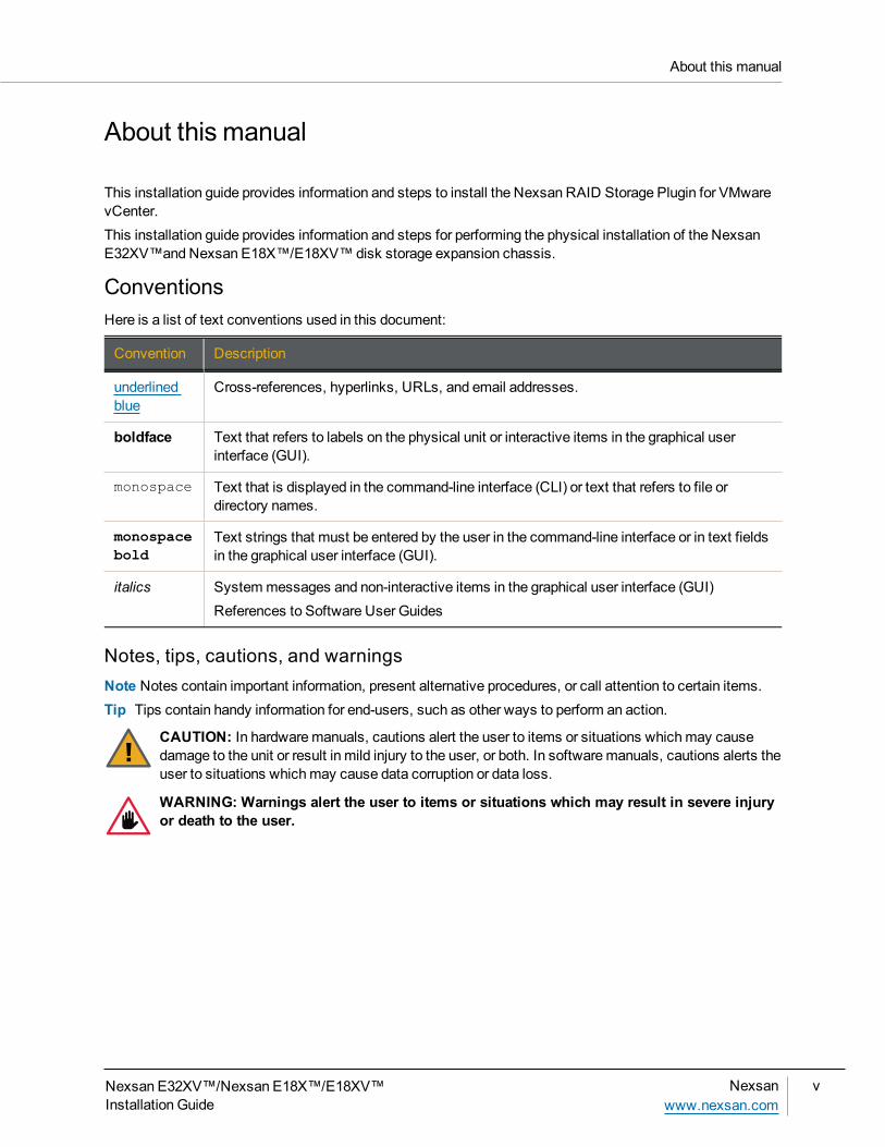
ConventionsHere is a list of text conventions used in this document:
Convention Description
underlinedblue
Cross-references, hyperlinks, URLs, and email addresses.
boldface Text that refers to labels on the physical unit or interactive items in the graphical userinterface (GUI).
monospace Text that is displayed in the command-line interface (CLI) or text that refers to file ordirectory names.
monospacebold
Text strings that must be entered by the user in the command-line interface or in text fieldsin the graphical user interface (GUI).
italics Systemmessages and non-interactive items in the graphical user interface (GUI)References to Software User Guides
Notes, tips, cautions, and warningsNote Notes contain important information, present alternative procedures, or call attention to certain items.Tip Tips contain handy information for end-users, such as other ways to perform an action.
CAUTION: In hardwaremanuals, cautions alert the user to items or situations whichmay causedamage to the unit or result in mild injury to the user, or both. In softwaremanuals, cautions alerts theuser to situations whichmay cause data corruption or data loss.
WARNING: Warnings alert the user to items or situations which may result in severe injuryor death to the user.
About this manual
Nexsan E32XV™/Nexsan E18X™/E18XV™Installation Guide
Nexsanwww.nexsan.com
v
Contacting NexsanNexsan Headquarters910 E Hamilton Ave,Campbell, CA 95008UNITED STATES
TelephoneWorldwide
1.866.2.NEXSAN (1.866.263.9726)1.760.690.1111
Contacting service and supportNexsan's Technical Services Group provides worldwide assistance with installation, configuration, softwaresupport, warranty and repair for all Nexsan products. A variety of service and support programs are availableto provide you with the level of coverage and availability your operation requires.
US and CanadaToll-free 1.866.263.9726Outside of North America 1.760.690.1111E-mail [email protected]
Europe, Middle East, AfricaBy phone +44 (0) 1332 596900E-mail [email protected]
About this manual
vi Nexsanwww.nexsan.com
Nexsan E32XV™/Nexsan E18X™/E18XV™Installation Guide
Related documentsThe following Nexsan product manuals contain related information:
Nexsan E32V™andNexsan E18™/E18V™RAID Storage Units Installation Guide
Nexsan E32V™andNexsan E18™/E18V™RAID Storage Units FRU Removal and Replacement Guide
Nexsan E32XV™andNexsan E18X™/E18XV™RAID Storage Expansion Units FRU Removal andReplacement Guide
Nexsan High-Density Storage User Guide
Nexsan E-Series™Snapshots and Replication User Guide
About this manual
Nexsan E32XV™/Nexsan E18X™/E18XV™Installation Guide
Nexsanwww.nexsan.com
vii
Safety noticesThis guide covers the Nexsan E32XV™/Nexsan E18X™/E18XV™digital storage expansion units only. Referto the relevant product manuals for information on other Nexsan storage or expansion units and other Nexsanproducts mentioned in this guide.Always observe the following precautions to reduce the risk of injury and equipment damage:
WARNING: There is a risk of ELECTRIC SHOCK if Nexsan E-Series™ components are removedor tampered with when unit power is on. Only a trained operator may remove certain customer-replaceable units (CRUs). The Nexsan E-Series™ storage units include the following CRUs:
Power Supply modules
RAID Controller and Expansionmodules
Disk drives
Fanmodules
Computer components and disk drives are sensitive to static discharge. Take precautions to dischargeany electrostatic charge from your person before and while handling components with your hands or anytools. Use an anti-static wrist-strap.
Ensure correct liftingmethods are used when removing the unit from its packaging and positioning it into itsrequired location. When lifting the system, two people at either end should lift slowly with their feet spreadout to distribute the weight. Always keep your back straight and lift with your legs.
When removing the unit from the packaging, DONOT lift the unit by any plastic parts or module handles onthe chassis. Doing somay cause damage to the chassis or to internal components, or both. Lift the unitONLY by the bottom edges of the chassis, using safe lifting practices.
The unit should only be installed in a clean, dry environment. The operating temperature is 5º to 30º C (41ºto 86º F), with operating relative humidity at 20 to 80%, non-condensing.
Do not install the unit in an enclosed cabinet or other small area without ventilation.
When installing the unit as a rack-mounted component, ensure that all Nexsan-suppliedmounting fixturesare secure. All bolts and screws should be fully tightened. Failure to comply with this may result in the unitnot being fully supported in the rack and could lead to the product falling from the rack, causing personalinjury or damage to other rack components.
Ensure that the rack is sufficiently stable by having wall anchors and/or stabilizing legs, and that the floorsupporting the rack has sufficient strength for the overall weight loading.
The cordset specification for the Nexsan E32XV™/Nexsan E18X™/E18XV™ in North America is USAIEC C13 to IEC C14, rated 125V/15A. When applying power to the unit, use ONLY the IEC power cordsoriginally supplied with it. Do NOT use other power cords, even if they appear identical to the suppliedcords.
Only a fully-trained Service Engineer is authorized to disassemble any other part of the unit, and then onlywhen the unit is powered off.
All Nexsan E-Series™Storage Systems havemultiple power connections; as a result, youmust removeall power leads to completely remove power from the unit.
Nexsan E-Series™Storage Systems do not have power switches. Do NOT attach the power cords untilthe unit is fully installed, with all disk drives in place.
Safety notices
viii Nexsanwww.nexsan.com
Nexsan E32XV™/Nexsan E18X™/E18XV™Installation Guide
Revision historyThis section lists updates and new material added to theNexsan E32XV™andNexsan E18X™/E18XV™RAID Storage Expansion Units Installation Guide.
NXS-EX2U-IG Rev. 04, January 2018Correction to Figure 3-20, showing correct cabling for second expansion unit.
NXS-EX2U-IG Rev. 03, October 2014Moved information regarding taking proper ESD precautions fromMount the unit on page 21 and put it into itsown section in Chapter 2, Take proper ESD precautions on page 14; updated all ESD warnings throughmanual, adding them to all sections that deal with handling components or disks, and referencing Take properESD precautions on page 14.
NXS-EX2U-IG Rev. 02, July 2014Changed name of document toNexsan E32XV™andNexsan E18X™/E18XV™RAID Storage UnitsInstallation Guide; incorporated information for newly-released Nexsan E32XV™RAID storage expansionunit; updated recommended rack depth under Required tools and equipment on page 13; added informationregarding themounting spacers being optional to Prepare themounting rails on page 18.
NXS-EX2U-IG Rev. 01, February 2014Changed formatting throughout to reflect Nexsan as an Nexsan brand; separated installation content fromFRU replacement content into two documents; changed name of document toNexsan E18X™/E18XV™RAID Storage Expansion Units Installation Guide.
Old formatVersion 1.6, October 2013Changed name of document toNexsan E18X/E18XV Installation andMaintenanceManual; updatedreferences to Nexsan E18X throughout document to include Nexsan E18XV, where appropriate;
Version 1.5, March 2013Updated references toNexsan RAID Storage User Manual; updatedMinimum Requirements on page ix;updated dimensions and power specifications on page 5; updated Attach Nexsan E18X toMain Storage Uniton page 21 to reflect new “hot-add” procedures; folded power-on instructions into Attach Nexsan E18X toMainStorage Unit on page 21.
Version 1.4.1, December 2012Corrected numbering and pagination errors.
Version 1.4, October 2012Updated cordset specifications on page vii, page 2, page 5, page 10, and page 24; updated accessory boxcontents on page 7; updated required tools and equipment on page 10; updated rail assembly and unitmounting instructions starting on page 13.
Version 1.3, July 2012Added patent information to page ii and back cover; updated Expansion Controller replacement instructions onpage 26; updated Common Terms and Abbreviations on page 37.
Version 1.2, May 2012
Revision history
Nexsan E32XV™/Nexsan E18X™/E18XV™Installation Guide
Nexsanwww.nexsan.com
ix
Addedminimum requirements on page ix; updated illustrations on page 1 and page 2 to call out drawer, PSU,and controller numbers; changed electrical specification on page 2, page 5, and page 10; added instructionsfor connecting a second Nexsan E18X unit and instructions for updating themain unit so it can accept aNexsan E18X unit to Attach Nexsan E18X toMain Storage Units on page 21.
Version 1.1, March 2012Added cord set specification to page vii, page 2, page 5, page 10, and page 24; corrected initial release dateon page ix.
Version 1.0, January 2012First release of theNexsan E18X Installation andMaintenanceManual.
Revision history
x Nexsanwww.nexsan.com
Nexsan E32XV™/Nexsan E18X™/E18XV™Installation Guide
Minimum requirementsBefore connecting a Nexsan E32XV™Nexsan E18X™/E18XV™ to your Nexsan E32V™NexsanE18™/E18V™ storage unit, the followingminimum requirements must bemet:
Firmware version:Q011.1014 or higher for one attached expansion unit
Q011.1047 or higher for two attached expansion units
Q0x1.1100 or higher to “hot-add” expansion units to a running system
TwoRAID Controllers (the Nexsan E32XV™/Nexsan E18X™/E18XV™will NOT work with single-controller units)
Each Nexsan expansion chassis can only be attached to specific main storage unit, as follows:A Nexsan E32XV™ can only be attached to a Nexsan E32V™.
A Nexsan E18XV™ can only be attached to a Nexsan E18V™.
A Nexsan E18X™ can only be attached to a Nexsan E18™.
Minimum requirements
Nexsan E32XV™/Nexsan E18X™/E18XV™Installation Guide
Nexsanwww.nexsan.com
xi
The Nexsan E32XV™andNexsan E18X™/E18XV™units are 2U, rack-mountable RAID storage expansionsystems which can hold up to 18 or 32 SATA, SAS, or SSD data disks.The Nexsan E18X™uses 3Gb/s SAS for internal communication between the RAID Controllers and harddisks. The V variant and the Nexsan E32XV™use 6Gb/s SAS for internal communication. There is noupgrade path between the Nexsan E18X™and the Nexsan E18XV™.Aside from the difference in internal communication speed, there is no operational difference between theNexsan E18X™and the Nexsan E18XV™.This chapter contains the following sections:
Front panel 2Rear panel 4Drawer interior 6Physical characteristics 8
Chapter 1
Chapter 1:Overview
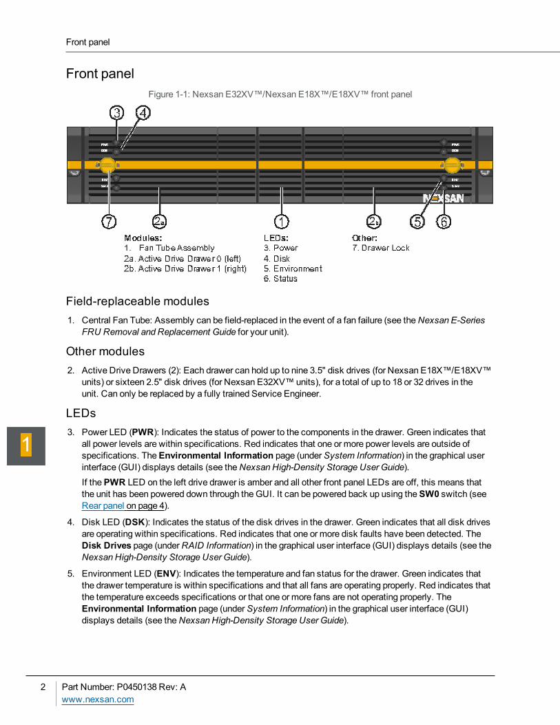
Front panelFigure 1-1: Nexsan E32XV™/Nexsan E18X™/E18XV™ front panel
Field-replaceable modules1. Central Fan Tube: Assembly can be field-replaced in the event of a fan failure (see theNexsan E-Series
FRU Removal and Replacement Guide for your unit).
Other modules2. Active Drive Drawers (2): Each drawer can hold up to nine 3.5" disk drives (for Nexsan E18X™/E18XV™
units) or sixteen 2.5" disk drives (for Nexsan E32XV™units), for a total of up to 18 or 32 drives in theunit. Can only be replaced by a fully trained Service Engineer.
LEDs3. Power LED (PWR): Indicates the status of power to the components in the drawer. Green indicates that
all power levels are within specifications. Red indicates that one or more power levels are outside ofspecifications. TheEnvironmental Information page (underSystem Information) in the graphical userinterface (GUI) displays details (see theNexsan High-Density Storage User Guide).If thePWR LED on the left drive drawer is amber and all other front panel LEDs are off, this means thatthe unit has been powered down through theGUI. It can be powered back up using theSW0 switch (seeRear panel on page 4).
4. Disk LED (DSK): Indicates the status of the disk drives in the drawer. Green indicates that all disk drivesare operating within specifications. Red indicates that one or more disk faults have been detected. TheDisk Drives page (underRAID Information) in the graphical user interface (GUI) displays details (see theNexsan High-Density Storage User Guide).
5. Environment LED (ENV): Indicates the temperature and fan status for the drawer. Green indicates thatthe drawer temperature is within specifications and that all fans are operating properly. Red indicates thatthe temperature exceeds specifications or that one or more fans are not operating properly. TheEnvironmental Information page (underSystem Information) in the graphical user interface (GUI)displays details (see theNexsan High-Density Storage User Guide).
Front panel
2 Part Number: P0450138 Rev: Awww.nexsan.com
1
6. Status LED (STAT): Indicates overall status. Green indicates that the unit is operating withinspecification. Amber indicates that the drawer is unlocked. Red indicates a fault in the drawer.If all STAT LEDs are red, this indicates that there is an issue with the unit that is not drawer-specific. TheEnvironmental Information page (underSystem Information) in the graphical user interface) displaysdetails (see theNexsan High-Density Storage User Guide).
Other items7. Drawer Lock: Secures the drive drawer in place. When this lock is disengaged, theSTAT LED turns
amber.
Chapter 1: Overview
Nexsan E32XV™/Nexsan E18X™/E18XV™Installation Guide
Nexsanwww.nexsan.com
3
1
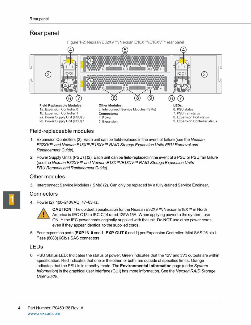
Rear panelFigure 1-2: Nexsan E32XV™/Nexsan E18X™/E18XV™ rear panel
PS
U
FA
N
PS
U
FA
N
0 - EXP • OUT - 1 0 - EXP • IN - 1
L0 L1 L0 L1 STAT
0 - EXP • OUT - 1 0 - EXP • IN - 1
L0 L1 L0 L1 STAT
2b2a
1b
1a
3 3
4 4
86 7 76
Field Replaceable Modules:
1a. Expansion Controller 0
1b. Expansion Controller 1
2a. Power Supply Unit (PSU) 0
2b. Power Supply Unit (PSU) 1
Other Modules:
3. Interconnect Service Modules (ISMs)
Connectors:
4. Power
5. Expansion
LEDs:
6. PSU status
7. PSU Fan status
8. Expansion Port status
9. Expansion Controller status
9
5
8
Field-replaceable modules1. Expansion Controllers (2). Each unit can be field-replaced in the event of failure (see theNexsan
E32XV™andNexsan E18X™/E18XV™RAID Storage Expansion Units FRU Removal andReplacement Guide).
2. Power Supply Units (PSUs) (2). Each unit can be field-replaced in the event of a PSU or PSU fan failure(see theNexsan E32XV™andNexsan E18X™/E18XV™RAID Storage Expansion UnitsFRU Removal and Replacement Guide).
Other modules3. Interconnect ServiceModules (ISMs) (2). Can only be replaced by a fully-trained Service Engineer.
Connectors4. Power (2): 100–240VAC, 47–63Hz.
CAUTION: The cordset specification for the Nexsan E32XV™/Nexsan E18X™ in NorthAmerica is IEC C13 to IEC C14 rated 125V/15A. When applying power to the system, useONLY the IEC power cords originally supplied with the unit. Do NOT use other power cords,even if they appear identical to the supplied cords.
5. Four expansion ports (EXP IN 0 and 1, EXP OUT 0 and 1) per Expansion Controller: Mini-SAS 26 pin I-Pass (8088) 6Gb/s SAS connectors.
LEDs6. PSU Status LED: Indicates the status of power. Green indicates that the 12V and 3V3 outputs are within
specification. Red indicates that one or the other, or both, are outside of specified limits. Orangeindicates that the PSU is in standby mode. TheEnvironmental Information page (underSystemInformation) in the graphical user interface (GUI) has more information. See theNexsan RAID StorageUser Guide.
Rear panel
4 Part Number: P0450138 Rev: Awww.nexsan.com
1
7. PSU fan LED: Indicates the status of the PSU fans. Green indicates that all fans are operating withinspecifications. Red indicates that one or more fans are either running too slowly or have failed. When thePSU is in standby mode, this LED is off. TheEnvironmental Information page (underSystemInformation) in the graphical user interface (GUI) has more information. See theNexsan RAID StorageUser Guide.
8. Expansion port LEDs (EXP IN L0 and L1, EXP OUT L0 and L1): Indicate the connection status for eachexpansion port. Green indicates that the SAS cable is properly connected. Flashing amber indicates thatthe cable is improperly connected. If no cable is connected, this LED is off.
9. Controller status LED (STAT): Indicates the status of the Expansion Controller:Flashing green indicates that the controller is operating within specifications.
Flashing red indicates that the controller is restarting.
Solid red indicates that there is an issue with the Expansion Controller. TheEnvironmentalInformation page (underSystem Information) in the graphical user interface (GUI) displays details(see theNexsan RAID Storage User Guide).
Chapter 1: Overview
Nexsan E32XV™/Nexsan E18X™/E18XV™Installation Guide
Nexsanwww.nexsan.com
5
1
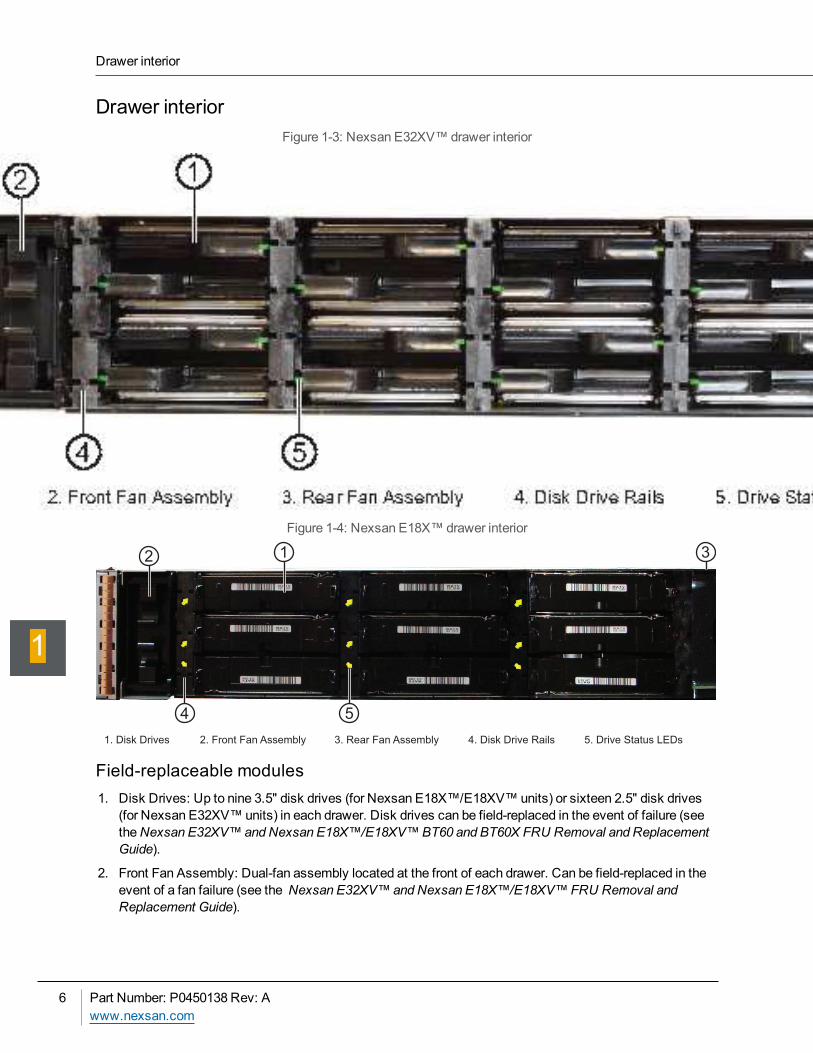
Drawer interiorFigure 1-3: Nexsan E32XV™drawer interior
Figure 1-4: Nexsan E18X™drawer interior
2 1 3
4 5
1. Disk Drives 3. Rear Fan Assembly2. Front Fan Assembly 4. Disk Drive Rails 5. Drive Status LEDs
Field-replaceable modules1. Disk Drives: Up to nine 3.5" disk drives (for Nexsan E18X™/E18XV™units) or sixteen 2.5" disk drives
(for Nexsan E32XV™units) in each drawer. Disk drives can be field-replaced in the event of failure (seetheNexsan E32XV™andNexsan E18X™/E18XV™BT60 and BT60X FRU Removal and ReplacementGuide).
2. Front Fan Assembly: Dual-fan assembly located at the front of each drawer. Can be field-replaced in theevent of a fan failure (see the Nexsan E32XV™andNexsan E18X™/E18XV™FRU Removal andReplacement Guide).
Drawer interior
6 Part Number: P0450138 Rev: Awww.nexsan.com
1
3. Rear Fan Assembly: Dual-fan assembly located at the rear of each drawer. Can be field-replaced in theevent of failure (see theNexsan E32XV™andNexsan E18X™/E18XV™BT60 BT60X FRU Removaland Replacement Guide).
Other modules4. Drive Guides: Align with plastic rails on disk drives to guide installation. These are integral to the drive
drawer and cannot be individually replaced.
LEDs5. Drive status: One for each disk drive slot. Solid green indicates that the disk is operating within
specifications and is not currently being accessed. Flashing green indicates disk activity. Red indicatesthat a disk fault has been detected and that the disk is not currently being used by the system. For diskdrive slots where no disk drive is installed, this LED is off.
Chapter 1: Overview
Nexsan E32XV™/Nexsan E18X™/E18XV™Installation Guide
Nexsanwww.nexsan.com
7
1
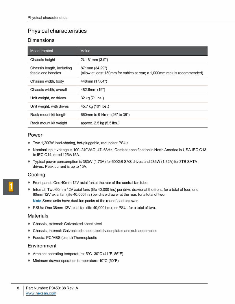
Physical characteristicsDimensions
Measurement Value
Chassis height 2U: 81mm (3.9")
Chassis length, includingfascia and handles
871mm (34.29")(allow at least 150mm for cables at rear; a 1,000mm rack is recommended)
Chassis width, body 448mm (17.64")
Chassis width, overall 482.6mm (19")
Unit weight, no drives 32 kg (71 lbs.)
Unit weight, with drives 45.7 kg (101 lbs.)
Rack mount kit length 660mm to 914mm (26" to 36")
Rack mount kit weight approx. 2.5 kg (5.5 lbs.)
PowerTwo 1,200W load-sharing, hot-pluggable, redundant PSUs.
Nominal input voltage is 100–240VAC, 47–63Hz. Cordset specification in North America is USA IEC C13to IEC C14, rated 125V/15A.
Typical power consumption is 383W (1.73A) for 600GB SAS drives and 286W (1.32A) for 3TB SATAdrives. Peak current is up to 15A.
CoolingFront panel: One 40mm 12V axial fan at the rear of the central fan tube.
Internal: Two 60mm 12V axial fans (life 40,000 hrs) per drive drawer at the front, for a total of four; one60mm 12V axial fan (life 40,000 hrs) per drive drawer at the rear, for a total of two.Note Some units have dual-fan packs at the rear of each drawer.
PSUs: One 38mm 12V axial fan (life 40,000 hrs) per PSU, for a total of two.
MaterialsChassis, external: Galvanized sheet steel
Chassis, internal: Galvanized sheet steel divider plates and sub-assemblies
Fascia: PC/ABS (blend) Thermoplastic
EnvironmentAmbient operating temperature: 5°C–30°C (41°F–86°F)
Minimum drawer operation temperature: 10°C (50°F)
Physical characteristics
8 Part Number: P0450138 Rev: Awww.nexsan.com
1
This docuemt is designed to enable the user to install and configure the Nexsan E32XV™/NexsanE18X™/E18XV™RAID storage unit quickly and safely. Please read this document carefully and review all ofthe information in this section before installing the unit.This chapter contains the following sections:
Taking delivery of the unit 10Before installation 13
Chapter 2
Chapter 2:Getting Started
Taking delivery of the unitUpon receipt of your Nexsan storage unit, inspect the packaging for damage that may have been sustained intransit. If there is visible damage on the packaging, contact your shipper before proceeding.
Unpack the unitCarefully unpack your Nexsan storage unit and inspect each item before installation.
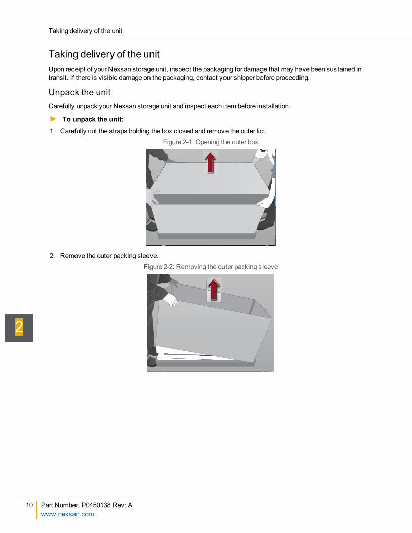
► To unpack the unit:1. Carefully cut the straps holding the box closed and remove the outer lid.
Figure 2-1: Opening the outer box
2. Remove the outer packing sleeve.Figure 2-2: Removing the outer packing sleeve
Taking delivery of the unit
10 Part Number: P0450138 Rev: Awww.nexsan.com
2
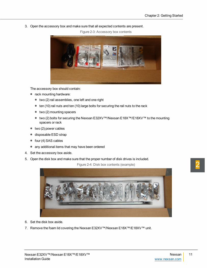
3. Open the accessory box andmake sure that all expected contents are present.Figure 2-3: Accessory box contents
The accessory box should contain:rack mounting hardware:
two (2) rail assemblies, one left and one right
ten (10) rail nuts and ten (10) large bolts for securing the rail nuts to the rack
two (2) mounting spacers
two (2) bolts for securing the Nexsan E32XV™/Nexsan E18X™/E18XV™ to themountingspacers or rack
two (2) power cables
disposable ESD strap
four (4) SAS cables
any additional items that may have been ordered
4. Set the accessory box aside.
5. Open the disk box andmake sure that the proper number of disk drives is included.Figure 2-4: Disk box contents (example)
6. Set the disk box aside.
7. Remove the foam lid covering the Nexsan E32XV™/Nexsan E18X™/E18XV™unit.
Chapter 2: Getting Started
Nexsan E32XV™/Nexsan E18X™/E18XV™Installation Guide
Nexsanwww.nexsan.com
11
2
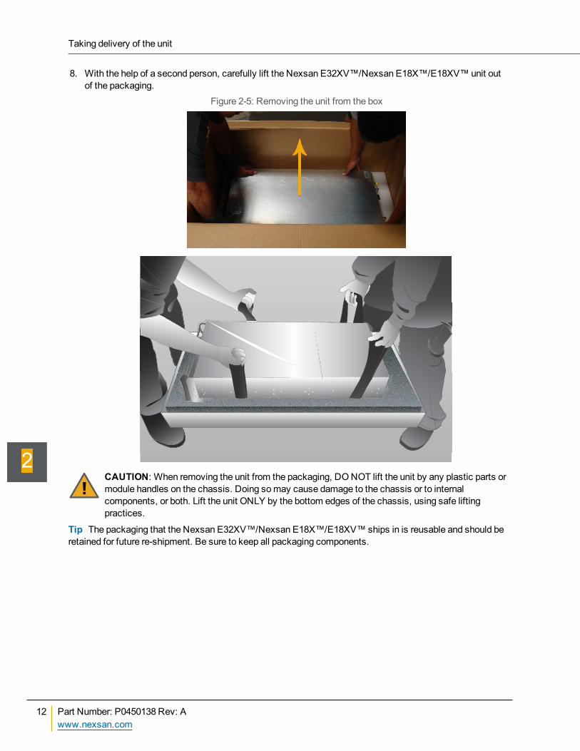
8. With the help of a second person, carefully lift the Nexsan E32XV™/Nexsan E18X™/E18XV™unit outof the packaging.
Figure 2-5: Removing the unit from the box
CAUTION: When removing the unit from the packaging, DONOT lift the unit by any plastic parts ormodule handles on the chassis. Doing somay cause damage to the chassis or to internalcomponents, or both. Lift the unit ONLY by the bottom edges of the chassis, using safe liftingpractices.
Tip The packaging that the Nexsan E32XV™/Nexsan E18X™/E18XV™ ships in is reusable and should beretained for future re-shipment. Be sure to keep all packaging components.
Taking delivery of the unit
12 Part Number: P0450138 Rev: Awww.nexsan.com
2
Before installationRequired tools and equipmentTo perform the installation, you will need the following tools and equipment:
a suitable equipment rack (1,000mm deep recommended, see Physical characteristics on page 8) withsufficient load capacity to hold the unit’s weightNote The rails that ship with the unit can accommodate a rack post depth of 660mm to 914mm (26" to 36").
a suitable source of A/C power: 100–240VAC, 47–63Hz, 15A
PH2 and PZ2 screwdrivers
Ethernet cables of sufficient length to connect theMGMT port on each RAID controller to the local areanetwork (LAN)
Prepare the siteBefore installing the unit, prepare the installation site and rack.Note Always install the Nexsan E32XV™/Nexsan E18X™/E18XV™expansion unit in the same rack as themain storage unit to which it will be attached or in an immediately adjacent rack.
► To prepare the site and rack for unit installation:Ensure that the ambient temperature at the installation site is between 5°C (41°F) and 30°C (86°F).
Place the rack so that full, unimpeded air flow can enter the front of the unit and exit the back of unit.
Ensure that the floor beneath themounting rack has enough load-bearing capacity to support the rack andall mounted components.
Fully stabilize the rack with wall anchors or stabilizing legs, or both, beforemounting the unit or any othercomponents onto the rack.
Ensure that the source of A/C power is near the rack and easily accessible.
Ensure that the rack is properly grounded per themanufacturer’s instructions and that proper ESDsafeguards are in place.
Ensure that the power drawn by the unit or units does not overload the available electrical supply (seePower on page 8). Cordset specification in North America is IEC C13 to IEC C14 rated 125V/15A.
Chapter 2: Getting Started
Nexsan E32XV™/Nexsan E18X™/E18XV™Installation Guide
Nexsanwww.nexsan.com
13
2
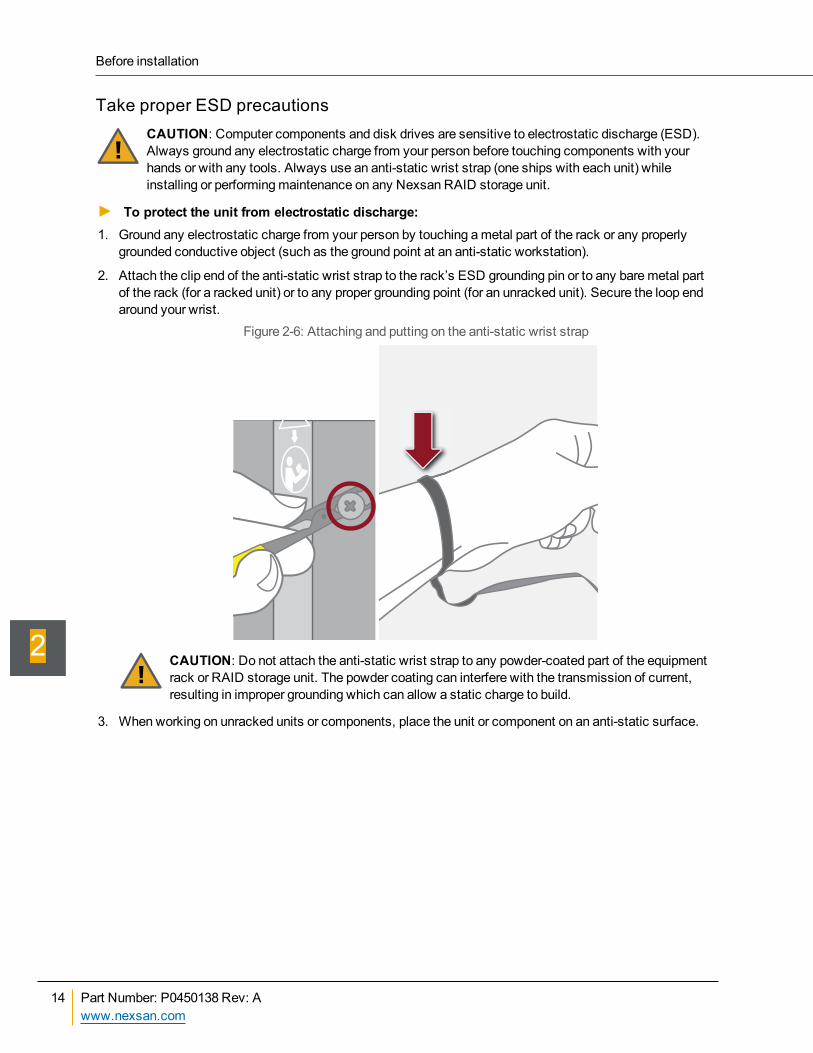
Take proper ESD precautionsCAUTION: Computer components and disk drives are sensitive to electrostatic discharge (ESD).Always ground any electrostatic charge from your person before touching components with yourhands or with any tools. Always use an anti-static wrist strap (one ships with each unit) whileinstalling or performingmaintenance on any Nexsan RAID storage unit.
► To protect the unit from electrostatic discharge:1. Ground any electrostatic charge from your person by touching ametal part of the rack or any properly
grounded conductive object (such as the ground point at an anti-static workstation).
2. Attach the clip end of the anti-static wrist strap to the rack’s ESD grounding pin or to any baremetal partof the rack (for a racked unit) or to any proper grounding point (for an unracked unit). Secure the loop endaround your wrist.
Figure 2-6: Attaching and putting on the anti-static wrist strap
CAUTION: Do not attach the anti-static wrist strap to any powder-coated part of the equipmentrack or RAID storage unit. The powder coating can interfere with the transmission of current,resulting in improper grounding which can allow a static charge to build.
3. When working on unracked units or components, place the unit or component on an anti-static surface.
Before installation
14 Part Number: P0450138 Rev: Awww.nexsan.com
2
Prepare the unitBefore installation, prepare the unit.
CAUTION: Before opening any of the drive drawers on the Nexsan E32XV™/NexsanE18X™/E18XV™, be sure that the internal temperature is 10°C (50°F) or above. If the unit has beenshipped or stored in very low temperatures, allow the unit to come to room temperature. Failure to dosomay result in internal cable damage.
CAUTION: Computer components and disk drives are sensitive to electrostatic discharge (ESD).Always ground any electrostatic charge from your person before touching components with yourhands or with any tools. Always use an anti-static wrist strap (one ships with each unit) whileinstalling or performingmaintenance on any Nexsan RAID storage unit. See Take properESD precautions on the previous page for detailed instructions.
► To prepare the unit for installation:1. Ground yourself with the included anti-static wrist strap (see Take proper ESD precautions on the
previous page).
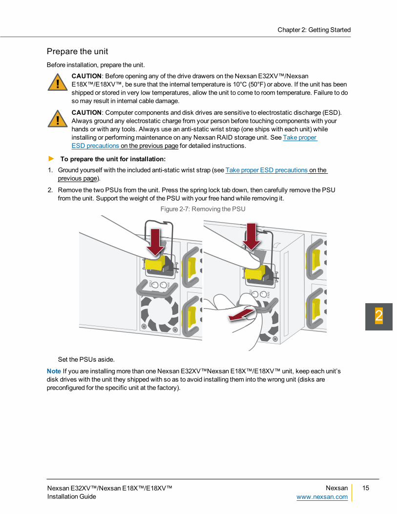
2. Remove the two PSUs from the unit. Press the spring lock tab down, then carefully remove the PSUfrom the unit. Support the weight of the PSU with your free hand while removing it.
Figure 2-7: Removing the PSU
PS
U
FA
N
PS
U
FA
N
Set the PSUs aside.
Note If you are installingmore than one Nexsan E32XV™Nexsan E18X™/E18XV™unit, keep each unit’sdisk drives with the unit they shipped with so as to avoid installing them into the wrong unit (disks arepreconfigured for the specific unit at the factory).
Chapter 2: Getting Started
Nexsan E32XV™/Nexsan E18X™/E18XV™Installation Guide
Nexsanwww.nexsan.com
15
2
The Nexsan E32XV™andNexsan E18X™/E18XV™must be attached to another Nexsan storage unit(Nexsan E32XV™, Nexsan E18XV™, or Nexsan E18™) to provide host connectivity and RAIDmanagement.This chapter contains the following sections:
Prepare themounting rails 18Mount the unit 21Restore the power supply units 23Reseat the expansion controllers 23Load the disk drives 25Attach expansion unit to main storage unit 29Remove an expansion unit from a running system 38
Chapter 3
Chapter 3:Installing the Unit
Prepare themounting rails
CAUTION: Ensure that your rack can support the total weight of all mounted components and thatyour floor is sufficiently strong.
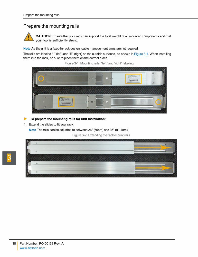
Note As the unit is a fixed-in-rack design, cablemanagement arms are not required.The rails are labeled “L” (left) and “R” (right) on the outside surfaces, as shown in Figure 3-1. When installingthem into the rack, be sure to place them on the correct sides.
Figure 3-1: Mounting rails’ “left” and “right” labeling
► To prepare the mounting rails for unit installation:1. Extend the slides to fit your rack.
Note The rails can be adjusted to between 26" (66cm) and 36" (91.4cm).Figure 3-2: Extending the rack-mount rails
Prepare themounting rails
18 Part Number: P0450138 Rev: Awww.nexsan.com
3
2. Attach the rack nuts (required) andmounting spacers (optional) to the front of the rack on the left and rightsides. The rack nuts should bemounted towards the interior of the rack.
Figure 3-3: Attaching the front rack nuts andmounting spacers
Note Themounting spacers are optional. They are provided to ensure that all components, such as thecentral fan tube and the rear active drawer fan packs, can be accessed for maintenance (see theNexsanE32XV™andNexsan E18X™/E18XV™RAID Storage Expansion Units FRU Removal andReplacement Guide). However, some rack doors cannot close when the unit is mounted with themounting spacers. Tomount the unit without the spacers, the rack nuts must be placed 2U apart. Usethe rail as a guide for rack nut placement.
3. Attach the rack nuts to the rear of the rack on the left and right sides. The rack nuts should bemountedtowards the interior of the rack.
Figure 3-4: Attaching the rear rack nuts
Chapter 3: Installing the Unit
Nexsan E32XV™/Nexsan E18X™/E18XV™Installation Guide
Nexsanwww.nexsan.com
19
3
4. Attach the rear slide of the left rail to the rack nuts by sliding the large part of themounting hole over therack nut and then pressing outward to seat the nut in the small part of themounting hole.
Figure 3-5: Attaching themounting rail in back
5. Repeat the previous step for the front of themounting rail.Figure 3-6: Attaching themounting rail in front
6. Repeat the previous two steps for the right mounting rail.
Themounting rails are now ready to receive the unit.Figure 3-7: Bothmounting rails in place
Note The rails may seem “loose” before the unit is mounted on them. This is normal. Once the unit is on therails, they are held in place by the body of the unit.
Prepare themounting rails
20 Part Number: P0450138 Rev: Awww.nexsan.com
3
Mount the unitCAUTION: Computer components and disk drives are sensitive to electrostatic discharge (ESD).Always ground any electrostatic charge from your person before touching components with yourhands or with any tools. Always use an anti-static wrist strap (one ships with each unit) whileinstalling or performingmaintenance on any Nexsan RAID storage unit. See Take properESD precautions on page 14 for detailed instructions.
CAUTION: The unit is heavy and requires two people to lift it and slide it onto themounting rails. DoNOT attempt to mount it onto themounting rails by yourself.
► To mount the unit on the mounting rails:1. Ground any electrostatic charge from your person by touching ametal part of the rack. Both people lifting
the unit must do this.
2. Attach one end of the anti-static wrist strap to a baremetal part of the rack. Secure the other end aroundyour wrist. Both people lifting the unit must do this. See Take proper ESD precautions on page 14.
3. With the help of a second person, carefully lift the unit so that the grooves in the side of the chassis lineup with themounting rails on the rack.
CAUTION: Only support the unit by placing hands under themetal chassis. Do NOT attempt tolift the unit by any plastic parts or module handles.
4. Carefully slide the unit onto themounting rails so that themounting ears sit against themounting spacers(if installed) or rack (see Prepare themounting rails on page 18).
Figure 3-8: Sliding the Nexsan E32XV™/Nexsan E18X™/E18XV™onto themounting rails
Chapter 3: Installing the Unit
Nexsan E32XV™/Nexsan E18X™/E18XV™Installation Guide
Nexsanwww.nexsan.com
21
3
5. Tightly bolt the front of the Nexsan E32XV™/Nexsan E18X™/E18XV™ to themounting spacers (ifinstalled) or rack face.
Figure 3-9: Bolting the unit in place
Mount the unit
22 Part Number: P0450138 Rev: Awww.nexsan.com
3
Restore the power supply unitsCAUTION: Computer components and disk drives are sensitive to electrostatic discharge (ESD).Always ground any electrostatic charge from your person before touching components with yourhands or with any tools. Always use an anti-static wrist strap (one ships with each unit) whileinstalling or performingmaintenance on any Nexsan RAID storage unit. See Take properESD precautions on page 14 for detailed instructions.
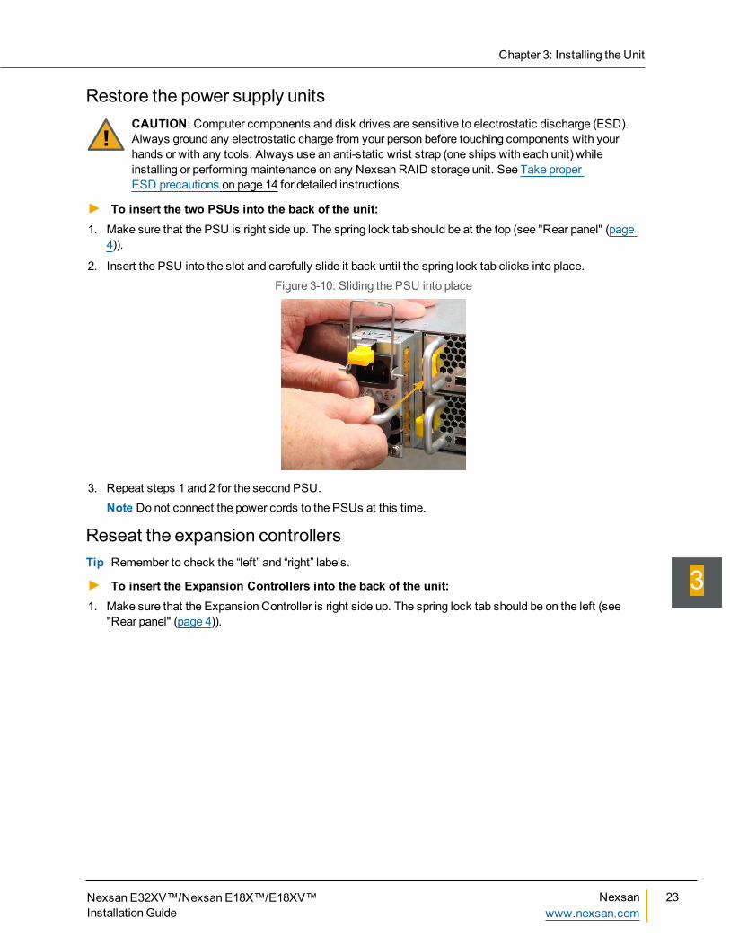
► To insert the two PSUs into the back of the unit:1. Make sure that the PSU is right side up. The spring lock tab should be at the top (see "Rear panel" (page
4)).
2. Insert the PSU into the slot and carefully slide it back until the spring lock tab clicks into place.Figure 3-10: Sliding the PSU into place
3. Repeat steps 1 and 2 for the second PSU.Note Do not connect the power cords to the PSUs at this time.
Reseat the expansion controllersTip Remember to check the “left” and “right” labels.
► To insert the Expansion Controllers into the back of the unit:1. Make sure that the Expansion Controller is right side up. The spring lock tab should be on the left (see
"Rear panel" (page 4)).
Chapter 3: Installing the Unit
Nexsan E32XV™/Nexsan E18X™/E18XV™Installation Guide
Nexsanwww.nexsan.com
23
3
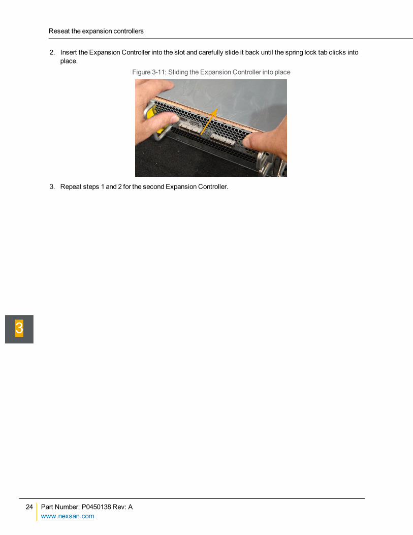
2. Insert the Expansion Controller into the slot and carefully slide it back until the spring lock tab clicks intoplace.
Figure 3-11: Sliding the Expansion Controller into place
3. Repeat steps 1 and 2 for the second Expansion Controller.
Reseat the expansion controllers
24 Part Number: P0450138 Rev: Awww.nexsan.com
3
Load the disk drivesCAUTION: Computer components and disk drives are sensitive to electrostatic discharge (ESD).Always ground any electrostatic charge from your person before touching components with yourhands or with any tools. Always use an anti-static wrist strap (one ships with each unit) whileinstalling or performingmaintenance on any Nexsan RAID storage unit. See Take properESD precautions on page 14 for detailed instructions.
CAUTION: Before opening any of the drive drawers on the Nexsan E-Series™ expansion unit, besure that the internal temperature is 10°C (50°F) or above. If the unit has been shipped or stored invery low temperatures, allow the unit to come to room temperature. Failure to do somay result ininternal cable damage.
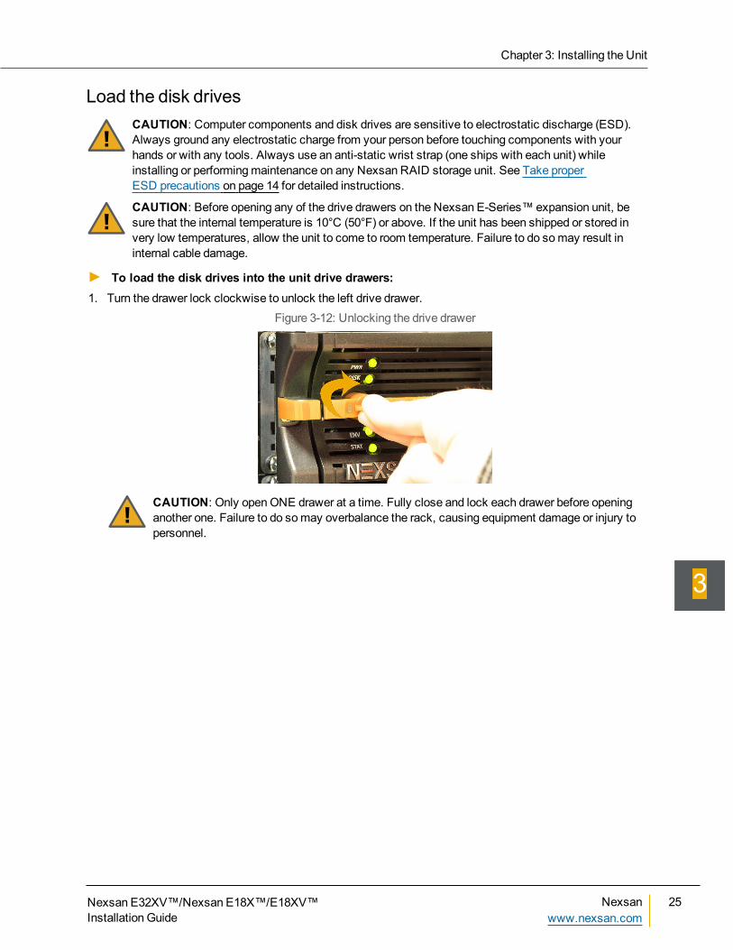
► To load the disk drives into the unit drive drawers:1. Turn the drawer lock clockwise to unlock the left drive drawer.
Figure 3-12: Unlocking the drive drawer
CAUTION: Only openONE drawer at a time. Fully close and lock each drawer before openinganother one. Failure to do somay overbalance the rack, causing equipment damage or injury topersonnel.
Chapter 3: Installing the Unit
Nexsan E32XV™/Nexsan E18X™/E18XV™Installation Guide
Nexsanwww.nexsan.com
25
3
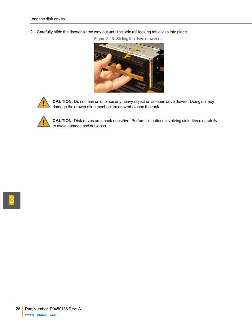
2. Carefully slide the drawer all the way out until the side rail locking tab clicks into place.Figure 3-13: Sliding the drive drawer out
CAUTION: Do not lean on or place any heavy object on an open drive drawer. Doing somaydamage the drawer slidemechanism or overbalance the rack.
CAUTION: Disk drives are shock sensitive. Perform all actions involving disk drives carefullyto avoid damage and data loss.
Load the disk drives
26 Part Number: P0450138 Rev: Awww.nexsan.com
3
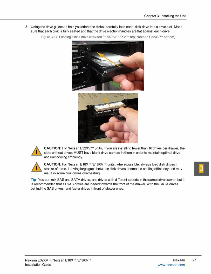
3. Using the drive guides to help you orient the disks, carefully load each disk drive into a drive slot. Makesure that each disk is fully seated and that the drive ejection handles are flat against each drive.
Figure 3-14: Loading a disk drive (Nexsan E18X™/E18XV™ top; Nexsan E32XV™bottom)
CAUTION: For Nexsan E32XV™units, if you are installing fewer than 16 drives per drawer, theslots without drives MUST have blank drive carriers in them in order to maintain optimal driveand unit cooling efficiency.
CAUTION: For Nexsan E18X™/E18XV™units, where possible, always load disk drives instacks of three. Leaving large gaps between disk drives decreases cooling efficiency andmayresult in some disk drives overheating.
Tip You canmix SAS and SATA drives, and drives with different speeds in the same drive drawer, but itis recommended that all SAS drives are loaded towards the front of the drawer, with the SATA drivesbehind the SAS drives, and faster drives in front of slower ones.
Chapter 3: Installing the Unit
Nexsan E32XV™/Nexsan E18X™/E18XV™Installation Guide
Nexsanwww.nexsan.com
27
3
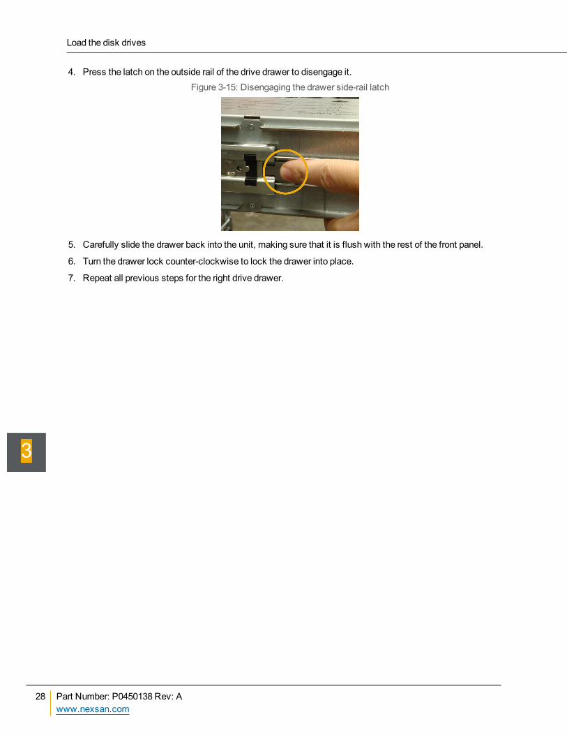
4. Press the latch on the outside rail of the drive drawer to disengage it.Figure 3-15: Disengaging the drawer side-rail latch
5. Carefully slide the drawer back into the unit, making sure that it is flush with the rest of the front panel.
6. Turn the drawer lock counter-clockwise to lock the drawer into place.
7. Repeat all previous steps for the right drive drawer.
Load the disk drives
28 Part Number: P0450138 Rev: Awww.nexsan.com
3
Attach expansion unit to main storage unitThe Nexsan E32XV™andNexsan E18X™/E18XV™ require another Nexsan unit to provide RAIDfunctionality and host/network connectivity. Up to two expansion units can be connected to a single mainstorage unit by “daisy-chaining” the two expansion units together. Expansion units should bemounted in thesame rack as the unit to which they are to be connected or in an immediately adjacent rack (see Prepare thesite on page 13).Note Each Nexsan expansion chassis can only be attached to specific main storage unit, as follows:
A Nexsan E32XV™ can only be attached to a Nexsan E32V™.
A Nexsan E18XV™ can only be attached to a Nexsan E18V™.
A Nexsan E18X™ can only be attached to a Nexsan E18™.
Prepare the main unitIn order for your Nexsan E-Series™ or BEASTNexsan E18™/E18V™ storage unit to communicate properlywith the expansion unit (or units), themain unit must be running the proper firmware version:
Q011.1014 or higher for one attached expansion unit
Q011.1047 or higher for two attached expansion units
Q0x1.1100 or higher to “hot-add” expansion units to a running system.
To check what version of firmware you have, access the graphical user interface (GUI) for themain unit (seetheNexsan RAID Storage User Manual for details) and click theSystem Information button on the left. OntheSystem Information page, ensure that the Firmware Version is the appropriate version. If it does not meetor exceed the specification, proceed to Update firmware below. If it does meet or exceed the specification, goto Connect the expansion unit below.
Update firmware1. Contact Technical Support (see About this manual on page v) and request to be emailed a link to the
latest firmware for your system.
2. In the email you receive, click the download link, then click Save in the File Download dialog box.
3. In theSave As dialog box, select a download location and click Save.
4. Find the .zip file on your computer and extract the files from it.
5. Follow the instructions for updating the firmware and Emergency Code firmware in the “Firmware UpdateInstructions.pdf” file that came in the firmware .zip file.
Connect the expansion unitDepending on your firmware level, you either a) can “hot add” an expansion unit to a running Nexsan E-Series™ storage unit, or b) must power down themain storage unit to attach the expansion unit. See Preparethemain unit above for requirements.
Hot-add expansion units to a powered-up system
If you are attaching the Nexsan expansion unit to a Nexsan E-Series™ storage unit with firmware versionQ0x1.1100 or higher, you can “hot-add” the expansion unit while themain unit is still powered on and running.Connecting the Nexsan E32XV™or Nexsan E18X™/E18XV™expansion unit requires the SAS cables thatshipped with the unit. See Unpack the unit on page 10.
Chapter 3: Installing the Unit
Nexsan E32XV™/Nexsan E18X™/E18XV™Installation Guide
Nexsanwww.nexsan.com
29
3
CAUTION: The cordset specification for the Nexsan E18X™/E18XV™ in North America is IEC C13to IEC C14 rated 110V/15A. When applying power to the unit, use ONLY the IEC power cordsoriginally supplied with it. Do NOT use other power cords, even if they appear identical to thesupplied cords.
CAUTION: The Nexsan E32XV™/Nexsan E18X™/E18XV™does not have power switches. Theonly way to apply power to the Nexsan E32XV™/Nexsan E18X™/E18XV™ is to attach the powercords. Do NOT attach the power cords until the unit is fully installed, with all disk drives in place andall connections to the local area network (LAN) and storage area network (SAN) connected.
CAUTION: Ensure that the A/C power socket/outlet is near the equipment and easily accessible.
► To hot-add an expansion unit to a running system:1. (Two expansion units only) Connect the two expansion units to each other:
Figure 3-16: Connecting the two expansion units together
a. Insert one SAS cable into theEXP OUT 0 port on the top expansion controller of the first Nexsanexpansion unit.
b. Insert the other end of the SAS cable into theEXP IN 0 port on the top Expansion Controller of thesecond Nexsan expansion unit.
c. Repeat steps a and b, connecting theEXP OUT 1 port of the top controller of the first Nexsanexpansion unit to theEXP IN 1 port of the top controller of the second Nexsan expansion unit.
d. Repeat steps a through c to connect the bottom expansion controllers of the Nexsan expansionunits.
CAUTION: Expansion Controller 0 on the first unit MUST be connected to Expansion Controller0 on the second unit, and Expansion Controller 1 on the first unit MUST be connected toExpansion Controller 1 on the second unit.
Attach expansion unit to main storage unit
30 Part Number: P0450138 Rev: Awww.nexsan.com
3
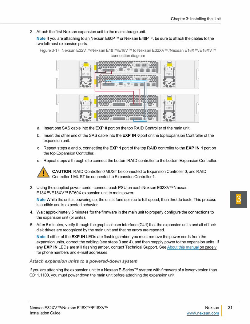
2. Attach the first Nexsan expansion unit to themain storage unit.Note If you are attaching to an Nexsan E60P™or Nexsan E48P™, be sure to attach the cables to thetwo leftmost expansion ports.Figure 3-17: Nexsan E32V™/Nexsan E18™/E18V™ to Nexsan E32XV™/Nexsan E18X™/E18XV™
connection diagram
PS
U
FA
N
PS
U
FA
N
EXP 0 EXP 1
STATMGMT SERIAL
SW0
NETWORK PORTS
HOST
L1L0
EXP 0 EXP 1
STATMGMT SERIAL
SW0
NETWORK PORTS
HOST
L1L0
PS
U
FA
N
PS
U
FA
N
0 - EXP • OUT - 1 0 - EXP • IN - 1
L0 L1 L0 L1 STAT
0 - EXP • OUT - 1 0 - EXP • IN - 1
L0 L1 L0 L1 STAT
a. Insert one SAS cable into theEXP 0 port on the top RAID Controller of themain unit.
b. Insert the other end of the SAS cable into theEXP IN 0 port on the top Expansion Controller of theexpansion unit.
c. Repeat steps a and b, connecting theEXP 1 port of the top RAID controller to theEXP IN 1 port onthe top Expansion Controller.
d. Repeat steps a through c to connect the bottom RAID controller to the bottom Expansion Controller.
CAUTION: RAID Controller 0MUST be connected to Expansion Controller 0, and RAIDController 1MUST be connected to Expansion Controller 1.
3. Using the supplied power cords, connect each PSU on each Nexsan E32XV™NexsanE18X™/E18XV™BT60X expansion unit to main power.NoteWhile the unit is powering up, the unit’s fans spin up to full speed, then throttle back. This processis audible and is expected behavior.
4. Wait approximately 5minutes for the firmware in themain unit to properly configure the connections tothe expansion unit (or units).
5. After 5minutes, verify through the graphical user interface (GUI) that the expansion units and all of theirdisk drives are recognized by themain unit and that no errors are reported.Note If either of theEXP IN LEDs are flashing amber, youmust remove the power cords from theexpansion units, correct the cabling (see steps 3 and 4), and then reapply power to the expansion units. Ifany EXP IN LEDs are still flashing amber, contact Technical Support. See About this manual on page vfor phone numbers and e-mail addresses.
Attach expansion units to a powered-down system
If you are attaching the expansion unit to a Nexsan E-Series™ system with firmware of a lower version thanQ011.1100, youmust power down themain unit before attaching the expansion unit.
Chapter 3: Installing the Unit
Nexsan E32XV™/Nexsan E18X™/E18XV™Installation Guide
Nexsanwww.nexsan.com
31
3
► To attach an expansion unit to a powered-down system:1. If necessary, power down themain unit:
a. Access themain unit’s graphical user interface (GUI).
b. Click theSystem Admin button on the left, then click theReboot tab.
c. On theReboot System screen, select System Shutdown, select the confirmation check box, andthen click Execute NOW.Themain unit shuts down all internal systems. TheSTAT LEDs on both RAID Controllers turn off.All front panel LEDs turn off except for the left PWR LED, which turns amber. The fans, however,still run.
d. Wait approximately oneminute, then remove the power cords from the sockets on both PSUs.
Themain storage unit is now ready to be attached to the expansion unit.
Attach expansion unit to main storage unit
32 Part Number: P0450138 Rev: Awww.nexsan.com
3
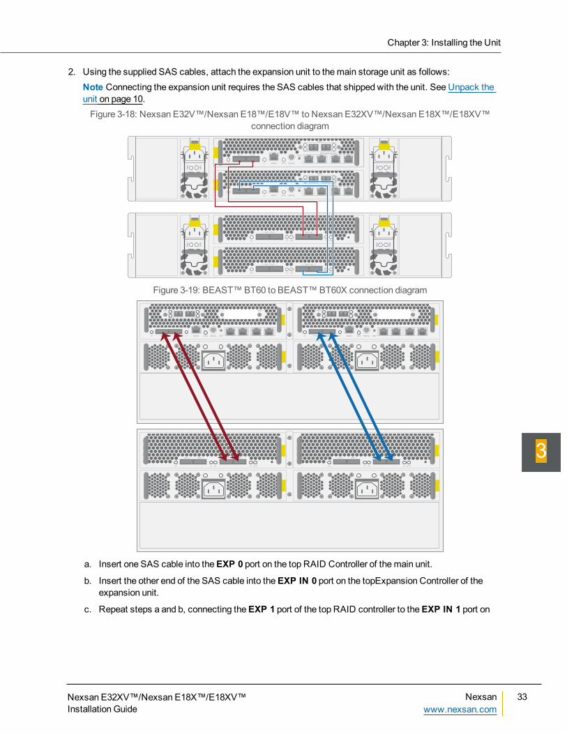
2. Using the supplied SAS cables, attach the expansion unit to themain storage unit as follows:Note Connecting the expansion unit requires the SAS cables that shipped with the unit. See Unpack theunit on page 10.Figure 3-18: Nexsan E32V™/Nexsan E18™/E18V™ to Nexsan E32XV™/Nexsan E18X™/E18XV™
connection diagram
PS
U
FA
N
PS
U
FA
N
EXP 0 EXP 1
STATMGMT SERIAL
SW0
NETWORK PORTS
HOST
L1L0
EXP 0 EXP 1
STATMGMT SERIAL
SW0
NETWORK PORTS
HOST
L1L0
PS
U
FA
N
PS
U
FA
N
0 - EXP • OUT - 1 0 - EXP • IN - 1
L0 L1 L0 L1 STAT
0 - EXP • OUT - 1 0 - EXP • IN - 1
L0 L1 L0 L1 STAT
Figure 3-19: BEAST™BT60 to BEAST™BT60X connection diagram
EXP 0 EXP 1 STATMGMT SERIAL
HOST
0
HOST
1
L1L0EXP 0 EXP 1 STATMGMT SERIAL
HOST
0
HOST
1
L1L0 SW0 SW0
EXP 0 EXP 1
L1 STATL0
EXP 0 EXP 1
L1L0
EXP 0 EXP 1
L1 STATL0
EXP 0 EXP 1
L1L0
a. Insert one SAS cable into theEXP 0 port on the top RAID Controller of themain unit.
b. Insert the other end of the SAS cable into theEXP IN 0 port on the topExpansion Controller of theexpansion unit.
c. Repeat steps a and b, connecting theEXP 1 port of the top RAID controller to theEXP IN 1 port on
Chapter 3: Installing the Unit
Nexsan E32XV™/Nexsan E18X™/E18XV™Installation Guide
Nexsanwww.nexsan.com
33
3
the top Expansion Controller.
d. Repeat steps a through c to connect thebottom RAID controller to the bottom Expansion Controller.
CAUTION: RAID Controller 0MUST be connected to Expansion Controller 0, and RAIDController 1MUST be connected to Expansion Controller 1.
Attach expansion unit to main storage unit
34 Part Number: P0450138 Rev: Awww.nexsan.com
3
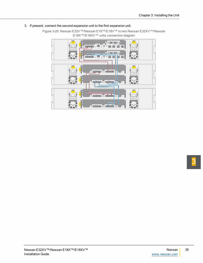
3. If present, connect the second expansion unit to the first expansion unit.Figure 3-20: Nexsan E32V™/Nexsan E18™/E18V™ to two Nexsan E32XV™/Nexsan
E18X™/E18XV™units connection diagram
Chapter 3: Installing the Unit
Nexsan E32XV™/Nexsan E18X™/E18XV™Installation Guide
Nexsanwww.nexsan.com
35
3
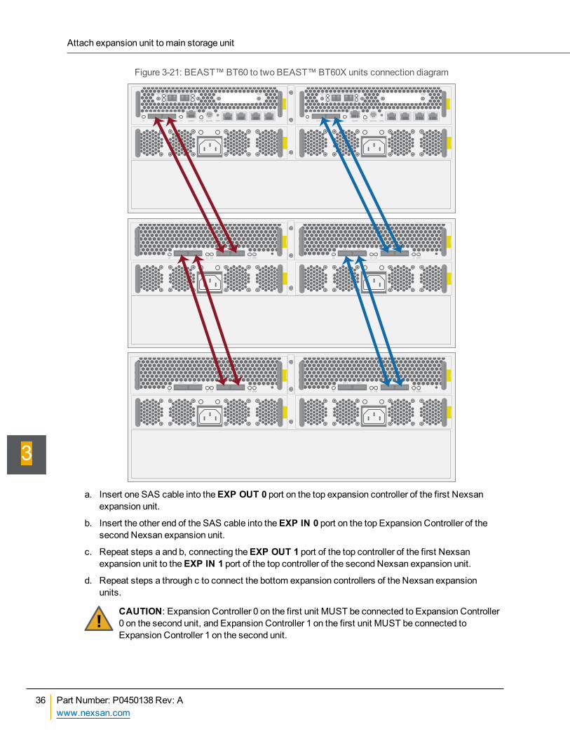
Figure 3-21: BEAST™BT60 to two BEAST™BT60X units connection diagram
EXP 0 EXP 1 STATMGMT SERIAL
HOST
0
HOST
1
L1L0EXP 0 EXP 1 STATMGMT SERIAL
HOST
0
HOST
1
L1L0 SW0 SW0
EXP 0 EXP 1
L1 STATL0
EXP 0 EXP 1
L1L0
EXP 0 EXP 1
L1 STATL0
EXP 0 EXP 1
L1L0
EXP 0 EXP 1
L1 STATL0
EXP 0 EXP 1
L1L0
EXP 0 EXP 1
L1 STATL0
EXP 0 EXP 1
L1L0
a. Insert one SAS cable into theEXP OUT 0 port on the top expansion controller of the first Nexsanexpansion unit.
b. Insert the other end of the SAS cable into theEXP IN 0 port on the top Expansion Controller of thesecond Nexsan expansion unit.
c. Repeat steps a and b, connecting theEXP OUT 1 port of the top controller of the first Nexsanexpansion unit to theEXP IN 1 port of the top controller of the second Nexsan expansion unit.
d. Repeat steps a through c to connect the bottom expansion controllers of the Nexsan expansionunits.
CAUTION: Expansion Controller 0 on the first unit MUST be connected to Expansion Controller0 on the second unit, and Expansion Controller 1 on the first unit MUST be connected toExpansion Controller 1 on the second unit.
Attach expansion unit to main storage unit
36 Part Number: P0450138 Rev: Awww.nexsan.com
3
4. Power up all units:
CAUTION: The cordset specification for the Nexsan E18X™/E18XV™ in North America is IECC13 to IEC C14 rated 110V/15A. When applying power to the unit, use ONLY the IEC powercords originally supplied with it. Do NOT use other power cords, even if they appear identical tothe supplied cords.
CAUTION: The Nexsan E32XV™/Nexsan E18X™/E18XV™does not have power switches.The only way to apply power to the Nexsan E32XV™/Nexsan E18X™/E18XV™ is to attach thepower cords. Do NOT attach the power cords until the unit is fully installed, with all disk drivesin place and all connections to the local area network (LAN) and storage area network (SAN)connected.
CAUTION: Ensure that the A/C power socket/outlet is near the equipment and easilyaccessible.
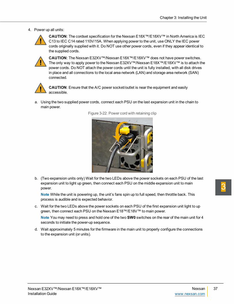
a. Using the two supplied power cords, connect each PSU on the last expansion unit in the chain tomain power.
Figure 3-22: Power cord with retaining clip
b. (Two expansion units only)Wait for the two LEDs above the power sockets on each PSU of the lastexpansion unit to light up green, then connect each PSU on themiddle expansion unit to mainpower.NoteWhile the unit is powering up, the unit’s fans spin up to full speed, then throttle back. Thisprocess is audible and is expected behavior.
c. Wait for the two LEDs above the power sockets on each PSU of the first expansion unit light to upgreen, then connect each PSU on the Nexsan E18™/E18V™ tomain power.Note Youmay need to press and hold one of the twoSW0 switches on the rear of themain unit for 4seconds to initiate the power-up sequence.
d. Wait approximately 5minutes for the firmware in themain unit to properly configure the connectionsto the expansion unit (or units).
Chapter 3: Installing the Unit
Nexsan E32XV™/Nexsan E18X™/E18XV™Installation Guide
Nexsanwww.nexsan.com
37
3
e. After 5minutes, verify through the graphical user interface (GUI) that the expansion units and all oftheir disk drives are recognized by themain unit and that no errors are reported.Note If either of theEXP IN LEDs are flashing amber, youmust remove the power cords from theexpansion units, correct the cabling (see steps 3 and 4), and then reapply power to the expansionunits. If any EXP IN LEDs are still flashing amber, contact Technical Support. See About thismanual on page v for phone numbers and e-mail addresses.
Remove an expansion unit from a running systemIf it becomes necessary to remove an expansion unit from your system, follow this procedure to ensure thatthe system continues to run smoothly.
► To remove an expansion unit from a running main storage system:1. Shut down or disconnect all hosts that are connected to RAID arrays or volumes that reside on the
expansion unit you wish to remove. There should be no I/O activity to or from any disk in the expansionunit.
2. In the graphical user interface (GUI), go toSystem Admin > Enclosure Config. TheConfigureEnclosures page is displayed.
3. For the expansion unit you wish to remove, click theUnload button to begin shutting down all RAID setson the expansion unit.
4. Go toSystem Information > Event Log. TheEvent Log page is displayed.
5. Refresh theEvent Log page until a series of four events appears:Enclosure N not accessible from C0Enclosure N not accessible from C0Enclosure N not accessible from C1Enclosure N not accessible from C1
When thesemessages appear, the expansion unit is ready to be physically disconnected.
6. Remove the SAS cables from theEXP connectors on themain unit.
7. Remove the power cables from the PSUs on the expansion unit.
Remove an expansion unit from a running system
38 Part Number: P0450138 Rev: Awww.nexsan.com
3
Glossary
Nexsan E32XV™/Nexsan E18X™/E18XV™Installation Guide
Nexsanwww.nexsan.com
39
Glossary
110Gb Ethernet
A 10 gigabit per second (Gb/s) Ethernetconnection using either fiber-optic cables ortwisted-pair copper wires.
10Gb iSCSIAn iSCSI connection that runs on a 10GbEthernet network.
10GbESee 10Gb Ethernet and 10Gb iSCSI.
Aactive drawer
A slide-out container on the front of Nexsan E-Series storage units that houses the disk drivesused by the unit for data storage. Alsosometimes referred to as a “pod” in event logsand other internal statistics.
Active Drawer TechnologyNexsan’s industry-first technology whichenables users to replace drives and performcertain maintenance tasks without powering offthe system and without interrupting service. Anadvanced, built-in cablemanagement systemallows cables to extend and retract with theactive drawer for easy servicing.
Anti-Vibration DesignNexsan’s proprietary disk installation schemewherein drives are loaded into the chassis inopposite-facing pairs. Disks in each pair rotatein opposite directions and serve to self-dampenany related vibration.
antistatic wrist strapAn anti-static device used to preventelectrostatic discharge (ESD) by safelygrounding a person working on electronic
equipment. Also called an ESD strap or agrounding bracelet.
arrayA linked group of one or more physical,independent hard disk drives. See also RAID.
Bbit
The smallest unit of digital data, representing a 0or a 1. Abbreviated “b”.
byteA unit of data that is 8 bits long. Often used foralphanumeric characters. Abbreviated “B”.
Ccache
Reserved areas of memory that are used tospeed up instruction execution, data retrieval,and data updating. In Nexsan storage units, amemory unit in the RAID controller thattemporarily holds user data.
CoolDrive TechnologyNexsan’s proprietary active drawer coolingsystem, which uses front- and rear-mountedfans to provide air intake and exhaust throughthe drawer. Air flows from the front of the drawerto the back through airflow channels locatedbetween the drive pairs. Either fan can fail; air isstill supplied to the drawer by the alternate fan.
Ddaisy-chain
The attachment of hardware to a computingsystem by connecting each component toanother similar component rather than directly tothe computing system that uses the component.Only the last component in the chain directlyconnects to the computing system. Forexample, up to two Nexsan E-Series expansion
Glossary
40 Nexsanwww.nexsan.com
Nexsan E32XV™/Nexsan E18X™/E18XV™Installation Guide
units can be daisy-chained to the back of oneNexsan E-Series main storage unit.
drawer front assemblyIn Nexsan E60 and E48 storage units (and theirV, VT and P variants), the assembly thathouses the active drawer status LEDs, the drivedrawer lock, and the front drive drawer fan.
drive drawerSee active drawer.
EE-Series
The series of Nexsan units that includes theNexsan E18, E48, and E60 storage units (andtheir V, VT and P variants), the Nexsan E32V,the Nexsan E18X, E48X, and E60X expansionunits (and their XV variants), and the NexsanE32XV. Nexsan E-Series units feature ActiveDrawer Technology, Anti-Vibration Design, andCoolDrive Technology.
electrostatic dischargeThe sudden andmomentary electric current thatflows between two objects at different electricalpotentials caused by direct contact or inducedby an electrostatic field. Potentially harmful toelectronic components.
ESDSee electrostatic discharge.
ESD strapSee anti-static wrist strap.
EthernetA system for connecting a number of computersystems to form a local area network (LAN),with protocols to control the passing ofinformation and to avoid simultaneoustransmission by two or more systems. Supportsdata transfer rates of 10, 100, 1,000, and 10,000megabits per second (Mb/s). 10, 100, and1,000Mb/s networks are often referred to as10BASE-T, 100BASE-T, and 1000BASE-T,
respectively. 10,000Mb/s networks are usuallyreferred to as 10Gb Ethernet or 10GbE.
Expansion ControllerA module of Nexsan E-Series expansion units(Nexsan E18X/XV, E32XV, E48X/XV, andE60X/XV) that connects via SAS to a Nexsanstorage unit’s RAID controller.
FFC port
See Fiber Channel port.
FCCThe Federal Communications Commission; theUnited States federal agency that regulateselectromagnetic emissions.
Fiber ChannelA gigabit (Gb) speed network technologyprimarily used for storage networking and thecurrent standard connection type for storagearea networks (SANs). Despite its name, FiberChannel signaling can run on both twisted-paircopper wire and fiber-optic cables.
Fiber Channel portAny entity that actively communicates over aFiber Channel network. Usually implemented ina device such as disk storage or a FiberChannel switch. Depending on the system, theFiber Channel ports on Nexsan storage unitscan support 2Gb/s, 4Gb/s, 8Gb/s, or 16Gb/sconnections.
Fiber Channel switchA network switch compatible with the FiberChannel protocol. Allows the creation of a FiberChannel network, which is currently the corecomponent of most storage area networks(SANs).
Glossary
Nexsan E32XV™/Nexsan E18X™/E18XV™Installation Guide
Nexsanwww.nexsan.com
41
GGb
Gigabit. Approximately one billion(1,000,000,000) bits.
GBGigabyte. Approximately one billion(1,000,000,000) bytes. Used to describe thestorage capacity of hard disk drives. A gigabyteis usually computed as 109 (1,000,000,000)bytes, but can also be computed as 230(1,073,741,824) bytes (often called a “binarygigabyte” and abbreviated GiB).
Gb/sGigabits (Gb) per second. Used to describe thespeed of network data transmission.
GB/sGigabytes (GB) per second. Used to describethe speed of network data transmission. 1 GB/sis eight times faster than 1Gb/s.
gigabit interface converterA standard for transceivers, commonly usedwith Gigabit (Gb) Ethernet and Fiber Channel,with a hot-swappable electrical interface.Gigabit interface converter ports can support awide range of physical media, from copper tooptical fiber, at lengths of up to hundreds ofkilometers.
graphical user interfaceA type of user interface that allows users tointeract with electronic devices using imagesrather than text commands. Nexsan storageunits use a graphical user interface for systemconfiguration.
grounding braceletSee anti-static wrist strap.
GUISee graphical user interface.
Hhot-plug
To insert a new piece of hardware into acomputerized system while the system isrunning. See also hot-swap.
hot-swapTo replace a failed or faulty component of acomputerized system while the system isrunning. See also hot-plug.
II/O
Input/Output. The communication between aninformation processing system (such as acomputer or a Nexsan storage system’sRAID controller), and the outside world (eitheran operator or another information processingsystem). Inputs are the signals or data receivedby the system, and outputs are the signals ordata sent from it.
IECThe International Electrotechnical Commission.Prepares and publishes international standardsfor all electrical, electronic, and relatedtechnologies.
interconnect servicemoduleA module of the Nexsan E-Series storage unitsthat provides connectivity between all modulesin the chassis.
IP addressInternet Protocol address. A numerical labelassigned to each device (such as a computer,printer, or Nexsan storage unit) on a computernetwork that uses TCP/IP for communication.
iSCSIInternet Small Computer System Interface. Atransport protocol that provides for the SCSIprotocol to be carried over a TCP/IP network.
Glossary
42 Nexsanwww.nexsan.com
Nexsan E32XV™/Nexsan E18X™/E18XV™Installation Guide
ISMSee Interconnect ServiceModule.
LLAN
See local area network.
LEDLight Emitting Diode. LEDs are used forindicator lights on the front and back of Nexsanstorage units.
link moduleA module of single-controller Nexsan E18/E18Vstorage units that fits into a RAID controller slotand provides connections to themid-plane.
local area networkA computer network that links devices within asmall geographic area, such as a building orgroup of adjacent buildings.
MMb
Megabit. Approximately onemillion (1,000,000)bits.
Mb/sMegabits (Mb) per second. Used to describe thespeed of network data transmission.
PPCIe
Peripheral Component Interconnect Express. Acomputer expansion card standard designed toreplace the older Peripheral ComponentInterconnect (PCI), PCI-eXtended (PCI-X), andAccelerated Graphics Port (AGP) standards.
podSee active drawer.
power supply unitA module that regulates electrical power to thecomponents of Nexsan storage units.
PSUSee power supply unit.
Rrack
A metal frame designed to hold hardwaredevices.
rack-mountedAttached to a rack.
rack mountHardware for attaching devices to a rack.
RAIDRedundant Array of Independent Disks. Asystem usingmultiple hard drives organized intoa single logical unit for the sharing or replicationof data in order to increase data integrity, fault-tolerance, and throughput. Also referred to as aRAID set. RAIDs are organized intoRAID levels, which describe their architectureand configuration.
RAID ControllerA hardware device, software program, orcombination of the two whichmanages thephysical disk drives in a RAID and presentsthem as a single logical unit to attacheddevices. The RAID Controllers in Nexsanstorage units are hardwaremodules. NexsanRAID Controllers also provide connections forsystem administration and configuration.
RAID levelA numeric indicator of the architecture used by aRAID. RAIDs can be built using anycombination of striping, mirroring, and parity.The levels are numbered from 0 through 6.SomeRAID levels can also be combined, andthese configurations are usually referred to witha two-digit number. For example, RAID 10 =RAID 1 + RAID 0.
Glossary
Nexsan E32XV™/Nexsan E18X™/E18XV™Installation Guide
Nexsanwww.nexsan.com
43
railA type of rack mount that allows a device to beeasily slid into and back out of a rack.
SSAN
See storage area network.
SASSerial Attached SCSI. A serial version of theSCSI interface. A point-to-point architecture thatuses a disk controller with four or more channelsthat operate simultaneously. Each full-duplexchannel, known as a SAS port, transfers data at1.5Gb/s, 3Gb/s, or 6Gb/s in each direction. SASalso supports Serial ATA (SATA) drives, whichcan bemixed with SAS drives in a variety ofconfigurations.
SATASerial Advanced Technology Attachment. Aconnection standard for fixed and removablehard disk drives.
SCSISmall Computer System Interface. A collectionof standards and proposed standards forinput/output (I/O) communication, primarilyintended for connecting storage subsystems ordevices to hosts.
SFPSmall Form-factor Pluggable. A type of gigabitinterface converter (GBIC) in a compact formfactor. The Fiber Channel ports or 10Gb iSCSIports on Nexsan storage devices are SFPs.
SSDSolid State Disk. A high-performance storagedevice that contains nomoving parts.
storage area networkAn architecture that provides for attachment ofremote computer storage devices to servers insuch a way that the devices appear as locallyattached to the operating system.
TTB
Terabyte. Approximately one trillion(1,000,000,000,000) bytes. Used to describe thestorage capacity of hard disk drives. A terabyteis usually computed as 1012(1,000,000,000,000) bytes, but can also becomputed as 240 (1,099,511,627,776) bytes(often called a “binary terabyte” and abbreviatedTiB).
TCP/IPTransmission Control Protocol/InternetProtocol. The set of communications protocolsused for the Internet and other similar networks.TCP provides reliable delivery of messagesbetween networked computers. IP usesnumeric IP addresses to join network segments.
UU
Unit. The standard unit of measure fordesignating the vertical usable space, or height,of racks. 1U is equal to 1.75 inches. A devicethat is described as being 1U in height may beshorter than 1.75 inches, but, due to the designof most racks, will still take up 1.75 inches ofrack space.
WWAN
Seewide area network.
wide area networkA telecommunication network that covers abroad area or that links across metropolitan,regional, or national boundaries. Wide areanetworks are used to connect local areanetworks and other types of networks together,so that users and computers in one location cancommunicate with users and computers in otherlocations.
Nexsan—SanDiego, USA
910 EHamilton Ave, CampbellCA 95008, United States
TechnicalServices:
North America: 1.866.2.NEXSAN (1.866.263.9726)
Worldwide: 1.760.690.1111
Support E-mail: [email protected]
SalesE-mail: [email protected]
Nexsan—European HeadOffice, UK
Units 33–35 Parker Centre, Mansfield RoadDerby, DE21 4SZ, United Kingdom
TechnicalServices:
Europe:+44 (0) 1332 596900
Worldwide: 1.760.690.1111
Support E-mail: [email protected]
SalesE-mail: [email protected]
Copyright © 2010–2018 Nexsan. AllRightsReserved.
Nexsan® and the Nexsan logo are trademarksor registered trademarksofNexsan.
All other trademarksand registered trademarksare the property of theirrespective owners.
This product is protected byone or more of the following patents, and otherpending patent applicationsworldwide: United StatespatentsUS8,191,841,US8,120,922; United Kingdom patentsGB2466535B, GB2467622B,GB2467404B, GB2296798B, GB2297636B
Part Number: P0450138 Rev: A