Embed Size (px)
Citation preview

Journal of Energy Technologies and Policy www.iiste.org
ISSN 2224-3232 (Paper) ISSN 2225-0573 (Online)
Vol.5, No.1, 2015
28
Methodology for Energy and Energy Analysis of Steam Boilers
Idehai O. Ohijeagbon M. Adekojo Waheed
Mechanical Engineering Department, University of Ilorin, P.M.B. 1515, Ilorin, igeria
Simeon. O. Jekayinfa
Agricultural Engineering Department, Ladoke Akintola University of Technology, Ogbomoso, Nigeria
Abstract
This paper presents a framework of thermodynamic, energy and exergy, analyses of industrial steam boilers.
Mass, energy, and exergy analysis were used to develop a methodology for evaluating thermodynamic properties,
energy and exergy input and output resources in industrial steam boilers. Determined methods make available an
analytic procedure for exergetic analysis on steam boilers for appropriate applications. Chemical exergy of the
material streams was considered to offer a more comprehensive detail on energy and exergy resource allocation
and losses of the processes in a steam boiler.
Keywords: exergy, energy, steam boilers, chemical exergy, exergy destruction
LIST OF SYMBOLS
LPFO low pour fuel oil Chemical symbols
stAFR stoichiometric air-fuel ratio (kg of air/kg of fuel) yxHC hydrocarbon (fossil fuel)
molecules
AAF actual air-fuel ratio (kg of air/kg of fuel) C carbon
imɺ inlet mass flow rate, kg/s H hydrogen
emɺ exit mass flow rate, kg/s O oxygen
Qɺ heat transfer rate to the system, kJ/s CO2 carbon dioxide
Iɺ exergy destruction rate, kJ/s H2O water
inlet specific flow exergy of material streams, kJ/s N2 Nitrogen
exit specific flow exergy of material streams, kJ/s Ar Argon
phε specific physical flow exergy, kJ/kg Sub- and Superscripts
chε specific chemical flow exergy, kJ/kg a air
h specific enthalpy, kJ/kg f fuel
s specific entropy, kJ/kg K p hot products
T Temperature, 0C, K w feed water
P Pressure, N/m2 s steam
chfuelxe
molar chemical exergy of fuel, kJ/kmol g exhaust flue gas
chOxe
2
molar chemical exergy of oxygen (O2), kJ/kmol 0a reference state of air
chCOxe
2
molar chemical exergy of carbon dioxide (CO2),
kJ/kmol
0 reference state
chOHxe
2
molar chemical exergy of water vapour (H2O),
kJ/kmol
atm atmospheric
g∆ the change in the standard Gibbs function, kJ/kmol in in
R molar or universal gas constant,
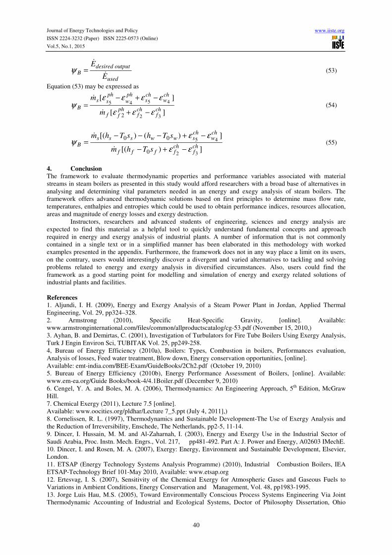
kJ/kmol K
out out
M molar mass of chemical substance, kg/kmol C combustion unit
Ein the energy input in the combustion unit, kJ/s H heat exchanging unit
HHV high or gross heating value of fuel. kJ/kg B boiler
LHV low or net heating value of fuel. kJ/kg ph physical
iε
eε
Journal of Energy Technologies and Policy www.iiste.org
ISSN 2224-3232 (Paper) ISSN 2225-0573 (Online)
Vol.5, No.1, 2015
29
)(lossHQ Heat loss in heat exchanging unit, kJ/s ch chemical
Greek letters η energy efficiency (%)
ψ exergy efficiency (%)
ε specific exergy (kJ/kg)
1. Introduction Steam boilers are closed vessels which are usually used to produce steam from water by combustion of fuel
(Rajput, 2006). The steam may further be utilised, for many other production processes. Owing to its great
significance in today’s industrial world, it is imperative to fully understand how to effectively assess the energy
resources utilization and outputs in steam boilers to ensure adequate energy management. The increasing energy
demand from emerging economies versus the day-to-day decreasing storages of energy resources, the rising cost
of fossil fuels and the considerable environmental impact connected with their exploitation are implications that
policy makers cannot disregard. These would consequently result in energy-related problems to become more
pronounced in the future (Tonon et al., 2006). Therefore, the need for effective and efficient energy utilization in
production systems cannot be overemphasised.
The impact of steam boilers on the environment, as regards competing for scarce energy resources as
diesel, coal, natural gas, etc. for its operation with attended environmental degradation like air pollution,
emission of green house gases, which continues to threaten quality of life and the ecosystem calls for closer
attention. For a given environment, energy which is convertible into other forms of energy is called useful
energy or exergy. Energy which is impossible to convert into other energy forms is called useless energy or
anergy (Ayhan and Demirtas, 2001). Exergy analysis appears to be a significant tool in addressing the impact of
energy resource utilization of steam boilers on the environment as raised in past work by Dincer et al. (2003) to
further the goal of more efficient energy resource utilization of steam boilers; enabling locations, types, and true
magnitudes of wastes and losses to be determined for steam boilers; revealing whether or not and how much it is
possible to design more efficient steam boiler systems by reducing the inefficiencies in the existing systems;
providing a sustainable development for steam boilers for sustainable supply of energy resources; and
distinguishing the high-quality and low-quality energy resources of steam boilers.
This study presents a framework to evaluate thermodynamic properties and performance variables
associated with material streams in boilers, such as, mass flow rate, temperature, enthalpy, entropy, energy and
exergy transfer with chemical, heat and material interactions, efficiencies, and exergetic losses in steam boilers.
2. Method
2.1 Methodological Framework
The framework for the methodology of this study was classified into 2 major categories as shown in Figure 1.
These include determination of operational variables and performance variables of steam boilers (Osemene,
2008, Ohijeagbon, 2012).
Methodological framework
Operation variables Performance variables
Figure 1: Methodological framework

Journal of Energy Technologies and Policy www.iiste.org
ISSN 2224-3232 (Paper) ISSN 2225-0573 (Online)
Vol.5, No.1, 2015
30
2.1.2 Operation variables
These are parameters concerned with the functioning of the boilers. They indicate measurable (direct operational
variables) and computable (indirect operational variables) properties which describe the generic thermodynamic
activities taking place in a boiler. Overviews of these properties are outlined in Figure 2.
(i) Measurable properties
These are usually monitored and recorded directly from inbuilt or attached boiler measurement indicators over a
specified period of time. An inventory data collection process is normally used to comprehensively collect boiler
information.
(ii) Computable properties
These properties are those that are not usually read directly from indicators, and as such would have to be
computed through the use of appropriate energy tables or charts; thermodynamic formulae, such as conservation
of mass and energy, and exergy balance equations.
2.1.3 Performance variables
These are parameters concerned with the performance of the boilers. Hence, they serve as indices to ascertain
and analyse various performance levels of the steam boilers. They include variations of energy and exergy values
and efficiencies of steam boilers in relation with input and output resources; and the magnitudes and types of
irreversibility (exergy losses) and the locations they occur in steam boilers. Methods for computing various
performance variables are enumerated in the theoretical framework.
2.2 Standard Environmental Reference State
Most analyses often involve the use of the natural environment-subsystem model described in Table 1 (Dincer
and Rosen, 2007). A distinguishing difference between exergy and other thermodynamic properties is that the
reference state for exergy is determined by the surroundings. In fact, exergy of matter will change if the state of
the surroundings changes, even when no changes occur in the system itself. A temperature of 25°C (298.15 K), a
pressure of 101.323 kPa and zero values for the height z0 and velocity v0 of the earth surface are typically taken
as reference state (Jorge Luis Hau, 2005).
Operational variables
Measurable
properties
Computable
properties
Temperatures Pressures
Mass flow rate of
water and steam
Amount of fuel
consumption
Enthalpies Entropies
Energy transfer
with heat and
material streams
interaction
Exergy transfer
with heat and
material streams
interaction
Other non-measurable
temperatures and mass
flow rates
Figure 2: Operational variables framework
Journal of Energy Technologies and Policy www.iiste.org
ISSN 2224-3232 (Paper) ISSN 2225-0573 (Online)
Vol.5, No.1, 2015
31
Table 1: A reference-environment model
Temperature: T0 = 298.15 K
Pressure: P0 = 1 atm (1 bar) = 101.325 kPa
Composition (i) Atmospheric air saturated with H20 at T0 and P0
having the following composition:
Air constituents Mole fraction
N2 0.7565
O2 0.2035
H2O 0.0303
Ar 0.0091
CO2 0.0003
H2 0.0001
(ii) The following condensed phases at T0 and P0:
Water (H2O)
Limestone (CaCO3)
Gypsum (CaSO4.2H2O)
Source: Adapted from Dincer and Rosen (2007)
2.3 Physical and Chemical Exergy
The total exergy transfer associated with material streams for a flow process comprises of the physical and
chemical exergy (Cornelissen, 1997, Dincer and Rosen, 2007, Talens et al., 2007, Chemical Exergy, 2011). The
flow exergy of a substance is the theoretically obtainable work when the substance is brought into total
equilibrium with the local environment. It can be split into chemical exergy and thermomechanical (physical)
flow exergy which is represented by (Ertesvag, 2007):
chph εεε += (1)
The specific physical flow exergy is expressed by:
)( 000 ssThhph −−−=ε (2)
where,
= specific flow exergy of material streams, kJ/kg
phε = specific physical flow exergy, kJ/kg
chε = specific chemical flow exergy, kJ/kg
h = specific enthalpy, kJ/kg
s = specific entropy, kJ/kg K
h0 = h (T0, P0) = enthalpy at reference state
s0 = s (T0, P0) = entropy at reference state
T0, P0 = reference state temperature and pressure
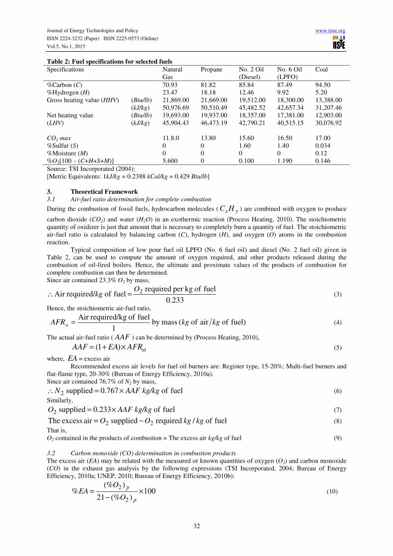
2.4 Specifications of Selected Hydrocarbon Fuels
Every fuel has a unique composition and energy content described by its fuel specifications (Table 2). Knowing
the fuel specifications is essential for determining combustion parameters such as combustion efficiency,
minimum air requirements, CO2 concentration and emissions factors (TSI Incorporated, 2004).
ε
Journal of Energy Technologies and Policy www.iiste.org
ISSN 2224-3232 (Paper) ISSN 2225-0573 (Online)
Vol.5, No.1, 2015
32
Table 2: Fuel specifications for selected fuels
Specifications Natural
Gas
Propane No. 2 Oil
(Diesel)
No. 6 Oil
(LPFO)
Coal
%Carbon (C) 70.93 81.82 85.84 87.49 94.50
%Hydrogen (H) 23.47 18.18 12.46 9.92 5.20
Gross heating value (HHV)
(Btu/lb) 21,869.00 21,669.00 19,512.00 18,300.00 13,388.00
(kJ/kg) 50,976.69 50,510.49 45,482.52 42,657.34 31,207.46
Net heating value
(LHV)
(Btu/lb) 19,693.00 19,937.00 18,357.00 17,381.00 12,903.00
(kJ/kg) 45,904.43 46,473.19 42,790.21 40,515.15 30,076.92
CO2 max 11.8.0 13.80 15.60 16.50 17.00
%Sulfur (S) 0 0 1.60 1.40 0.034
%Moisture (M) 0 0 0 0 0.12
%O2[100 – (C+H+S+M)] 5.600 0 0.100 1.190 0.146
Source: TSI Incorporated (2004);
[Metric Equivalents: 1kJ/kg = 0.2388 kCal/kg = 0.429 Btu/lb]
3. Theoretical Framework
3.1 Air-fuel ratio determination for complete combustion
During the combustion of fossil fuels, hydrocarbon molecules ( yxHC ) are combined with oxygen to produce
carbon dioxide (CO2) and water (H2O) in an exothermic reaction (Process Heating, 2010). The stoichiometric
quantity of oxidizer is just that amount that is necessary to completely burn a quantity of fuel. The stoichiometric
air-fuel ratio is calculated by balancing carbon (C), hydrogen (H), and oxygen (O) atoms in the combustion
reaction.
Typical composition of low pour fuel oil LPFO (No. 6 fuel oil) and diesel (No. 2 fuel oil) given in
Table 2, can be used to compute the amount of oxygen required, and other products released during the
combustion of oil-fired boilers. Hence, the ultimate and proximate values of the products of combustion for
complete combustion can then be determined.
Since air contained 23.3% O2 by mass,
233.0
fuel of kgper required fuel of required/Air 2O
kg =∴ (3)
Hence, the stoichiometric air-fuel ratio,
)fuel of air of ( massby 1
fuel of grequired/kAir kgkgAFRst = (4)
The actual air-fuel ratio ( AAF ) can be determined by (Process Heating, 2010),
stAFREAAAF ×+= )1( (5)
where, EA = excess air
Recommended excess air levels for fuel oil burners are: Register type, 15-20%; Multi-fuel burners and
flat-flame type, 20-30% (Bureau of Energy Efficiency, 2010a).
Since air contained 76.7% of N2 by mass,
fuel of 767.0 supplied 2 kg/kgAAFN ×=∴ (6)
Similarly,
fuel of 233.0 supplied 2 kg/kgAAFO ×= (7)
fuel of / required supplied air excess The 22 kgkgOO −= (8)
That is,
O2 contained in the products of combustion = The excess air kg/kg of fuel (9)
3.2 Carbon monoxide (CO) determination in combustion products
The excess air (EA) may be related with the measured or known quantities of oxygen (O2) and carbon monoxide
(CO) in the exhaust gas analysis by the following expressions (TSI Incorporated, 2004; Bureau of Energy
Efficiency, 2010a; UNEP, 2010; Bureau of Energy Efficiency, 2010b):
100)(%21
)(%%
2
2×
−=
p
p
O
OEA (10)

Journal of Energy Technologies and Policy www.iiste.org
ISSN 2224-3232 (Paper) ISSN 2225-0573 (Online)
Vol.5, No.1, 2015
33
100
2
)(%)(%21
2
)(%)(%
%
2
2
×
−−
−
=p
p
pp
COO
COO
EA (11)
where,
%EA = percentage excess air
(%O2)p = percentage oxygen from proximate (volumetric) analysis
(%CO)p = percentage carbon monoxide from proximate (volumetric) analysis
Equation (11) can be re-arranged and expressed in terms of percentage carbon monoxide as follows:
)1(
212)1()(%2)(%
2
EA
EAEAOCO
pp
+
××−+×= (12)
3.3 The schematic of the boiler plants
The schematic diagrams shown in Figures 3 can be used to analyse the mass flow rate, energy and exergy
balances and exergetic efficiencies of boilers (Saidur et al., 2010). The schematic diagrams of the combustion
and heat exchanging units respectively shown in Figures 3 may be separately analysed to establish the mass flow
rate of the material streams in the boilers. Combustion of fuel takes place in the combustion unit of the boiler,
while the heat carried by the hot flue gas from the combustion unit is used to transform liquid water to steam in
the heat exchanging unit.
3.4 Thermodynamic and exergetic analysis determination
An exergetic analysis involves mass, energy and exergy balance for each plant unit, and exergetic efficiency for
each of them (Modesto and Nebra, 2009). The mass, energy and exergy balances at steady state for the material
flows in a boiler system with negligible potential and kinetic energy changes can be expressed, respectively by
equations (13) to (15) (Aljundi, 2009, Modesto and Nebra, 2009, Saidur et al., 2010).
∑∑ = ei mm ɺɺ (13)
∑ ∑−= iiee hmhmQ ɺɺɺ (14)
∑∑ −= eeii mmI εε ɺɺɺ (15)
The exergetic balance of a boiler can be determined using equations (13) to (15).
where,
imɺ = inlet mass flow rate, kg/s
emɺ = exit mass flow rate, kg/s
Qɺ = heat transfer rate to the system, kJ/s
7 5
4
1
3 6
Figure 3: Schematic diagram of combustion and heat exchanging units in a boiler
Hot
product
s
Fuel
Air
Combustio
n unit
Water
Exhaust
flue gas
Steam Heat loss
Heat
exchangin
g unit
2

Journal of Energy Technologies and Policy www.iiste.org
ISSN 2224-3232 (Paper) ISSN 2225-0573 (Online)
Vol.5, No.1, 2015
34
Iɺ = exergy destruction rate, kJ/s
hi = inlet enthalpy of material streams, kJ/kg
he = exit enthalpy of material streams, kJ/kg
= inlet specific flow exergy of material streams, kJ/kg
= exit specific flow exergy of material streams, kJ/kg
1. Mass balance of material streams
Appropriate mass and energy balance as stated by equation (13) and equation (14) may be applied to a
boiler system with the evaporation ratio and air fuel ratio and may be used to determine masses of substances of
all material streams in the boiler, such as; air ( amɺ ), fuel ( fmɺ ), hot products ( pmɺ ), feed water ( wmɺ ), steam
( smɺ ) and exhaust flue gases ( gmɺ ) respectively.
hence,
pfa mmm ɺɺɺ =+ (16)
gp mm ɺɺ = (17)
sw mm ɺɺ = (18)
The mass flow rate of fuels and steam can be computed by
3600/ dqm m ×=ɺ (19)
where,
mɺ = mass rate of substance, kg/s
qm = rate of material stream, litres/hr
d = relative density of substance
The evaporation ratio of a boiler is given by (Bureau of Energy Efficiency, 2010b);
nconsumptio fuel ofQuantity
generation steam ofQuantity ratio,n Evaporatio =rE (20)
Equation (20) may simply be expressed as the quotient of mass flow rates of steam and fuel as shown in equation
(21)
f
sr
m
mE
ɺ
ɺ= (21)
Computed mass flow rates of material streams of a boiler operation can be used to determine other
thermodynamic properties of materials streams, such as enthalpy and entropy at different states.
2. Temperature, enthalpy and entropy of feed water and steam
The enthalpy and entropy of feed water may be determined at a saturation temperature of 100 0C or at
other appropriate temperatures, while the saturation temperatures corresponding to their respective steam
pressures may be obtained from saturated water and steam tables (Cengel and Boles, 2006). Superheated
temperatures at the given steam pressures may be used where applicable for superheated steams.
3. Combustion temperatures
From an energy balance analysis of a combustion process, the combustion temperature can be
calculated as follows (Process Heating, 2010),
)]1([ AAFc
hTT
p
rcac
+×+= (22)
where,
Tc = combustion temperature
Tca = temperature of the combustion air before entering the burner
hr = heat of reaction (hr = LHV, if exhaust gas streams is above 60 0C, (Kitto and Stultz, 2005) cp = specific heat
of fuel at ambient temperature of products of combustion
To maintain satisfactory working conditions for personnel around a boiler, a cold face temperature or
boiler room ambient temperature, Tar of 57 0C (135
0F) or less is considered satisfactory (Kitto and Stultz, 2005).
The following data may be used to calculate the values of the combustion temperature, Tc for LPFO and
diesel operated boilers:
iε
eε
Journal of Energy Technologies and Policy www.iiste.org
ISSN 2224-3232 (Paper) ISSN 2225-0573 (Online)
Vol.5, No.1, 2015
35
Tca = Ta
hr(LPFO) = 40,515.15 kJ/kg, hr(diesel) = 42,790.21 kJ/kg
AAF(LPFO) = 16, AAF(diesel) = 17
The specific heat of petroleum oils can be modeled as follows (Petroleum, 2011):
]103913.36831.1[1 3
arp Td
c −×+= (23)
where,
d = relative density at 15 0C
cp = specific heat, kJ/kg K
Tar = ambient boiler room temperature
d = relative density = 0.95 for LPFO and 0.86 for diesel at 15 0C (Armstrong, 2010)
hence, the values of cp were obtained as follows from equation (23);
KkgkJcLPFOp / 866.1
)(= , KkgkJc
dieselp / 9612.1)(
=
Using the values of cp obtained above, the values of Tc = Tf can be obtained from equation (22) with their
different combustion air temperature, Tca.
4. Enthalpy and entropy of inlet air
The enthalpy and entropy of inlet air can be evaluated for inlet air temperature, Ta for different boilers
operation from the ideal gas properties of air tables (Cengel and Boles, 2006).
5. Enthalpy of hot products
Applying the energy balance equation (14) to the combustion unit shown in Figure 3 and assuming heat
was transferred adiabatically (Saidur et al., 2010), the enthalpy of the hot products can be determined using
ppaaff hmhmhm ɺɺɺ =+ (24)
6. Temperature of exhaust flue gases
The steady-state efficiency of combustion is the ratio of the useful heat delivered to the process to the
heat content of the fuel (Process Heating, 2010). The combustion efficiency is given by:
HHV
TTcAAF gcpcomb
)]()1[( −××+=η (25)
where,
cp = specific heat of fuel at ambient temperature of products of combustion
HHV = Gross or high heating value of fuel
The benchmark combustion efficiency for various fuels, are given as: coal 90.3%, oil residual 89.6%,
oil distillate 88.7%, natural Gas 85.7% (ETSAP, 2010). Hence,
%6.89)(
=LPFOcombη , %7.88
)(=
dieselcombη
HHV(LPFO) = 42,657.34 kJ/kg, HHV(diesel) = 45,482.52 kJ/kg (Table 2),
AAF(LPFO) = 16, AAF(diesel) = 17,
CkgkJcLPFOp
0 /866.1)(
= , CkgkJcdieselp
0 /9612.1)(
=
Equation (25) may be re-written as equation (26) and can be used to evaluate the exhaust flue gas
temperatures
p
combcg
cAAF
HHVTT
×+
×−=
)1(
η (26)
7. Enthalpy of exhaust flue gases
Enthalpies of most gases used in combustion calculations can be curve-fitted by the simple second order
equation (Kitto and Stultz, 2005):
cbTaTh ++= 2 (27)
where,
h = enthalpy in Btu/lb
T = temperature in degrees, 0F
a, b and c are coefficients with the following values for T (0-500 0F) given as:

Journal of Energy Technologies and Policy www.iiste.org
ISSN 2224-3232 (Paper) ISSN 2225-0573 (Online)
Vol.5, No.1, 2015
36
a = 1.683x10⁻⁵
b = 0.233
c = -18.03
Equation (27) can be used to evaluate the enthalpy of the exhaust flue gases. It should be noted that the constants
a, b and c are stated only for the quoted temperature range given in 0F.
8. Entropy of combustion fuel gases
The entropy generated from a source can be expressed as follows (Cengel and Boles, 2006);
source
sourcegen
T
qs = (28)
where,
sgen = entropy generated from the source, kJ/kg K
qsource = heat transfer from a source to a sink, kJ/kg
Tsource = temperature of the source, 0K
A study of the thermodynamic processes taking place between the combustion and the heat exchanging
units shows that: the entropy generated from the combustion unit is the entropy of the combustion fuel gas, sf,
the heat transfer from the combustion unit to the heat exchanging unit equals the energy value of the hot products,
hp and the temperature of the source is the combustion fuel temperature, Tf.
hence, equation (28) can be re-written as:
f
p
fT
hs = (29)
The entropy of the combustion fuel gases can be determined by equation (29).
9. Entropy of hot products
The entropy of the hot products can be determined by equation (30), where Tp is the temperature of the
hot products
p
pp
T
hs = (30)
10. Entropy of exhaust flue gases
The change in entropy of an ideal gas can be expressed by (Cengel and Boles, 2006),
1
2
1
212 lnln
p
pR
T
Tcss p −=− (31)
where, s1, T1 and p1 defines the reference state entropy, temperature and pressure, while s2, T2 and p2 defines the
thermodynamic state entropy at a given temperature and pressure, and R is the specific gas constant.
At the exhaust of the boiler, the change in entropy of the exhaust flue gases can be determined by
setting s2 = sg, s1 = sa, T2 = Tg, T1 = Ta, p2 = pg = p1 = pa = patm, in equation (31), in which
sg = exhaust flue gas specific entropy
Tg = exhaust flue gas temperature
pg = exhaust flue gas pressure
sa = reference state entropy of air (at Ta and pa)
Ta = reference state temperature of air
pa = reference state pressure of air = 1atm (Turns and Kraige, 2007)
patm = atmospheric pressure = 1atm
cp = cpg ≅ cpa ≅ 1 kJ/kg K (cpg and cpa are the specific heat of exhaust flue gas and air)
hence, equation (31) reduces to
a
gpag
T
Tcss ln+= (32)
At KkgkJsKT aa / 29559.1 , 200 == (Cengel and Boles, 2006)
The entropy of the exhaust flue gases can be determined by equation (32).
11. Chemical exergy of fuels
Complete combustion of a general hydrocarbon with atmospheric air is written as (Cengel and Boles,

Journal of Energy Technologies and Policy www.iiste.org
ISSN 2224-3232 (Paper) ISSN 2225-0573 (Online)
Vol.5, No.1, 2015
37
2006, Roger and Mayhew, 1992),
OHy
xCOOy
xHC yx 2222
)4
( +→++ (33)
Where yx and are constant coefficients that characterises the hydrocarbon and combustion process. Assuming
no irreversibility, the molar chemical exergy of reactants and products can be developed as expressed by
(Chemical Exergy, 2011).
ch
OHxchCOx
chOx
chfuelx e
yxege
yxe
222 2)
4( ++∆−→++ (34)
where,
chfuelxe = molar chemical exergy of fuel, kJ/kmol
chOxe
2= molar chemical exergy of oxygen (O2), kJ/kmol
chCOxe
2= molar chemical exergy of carbon dioxide (CO2), kJ/kmol
chOHxe
2= molar chemical exergy of water vapour (H2O), kJ/kmol
g∆ = the change in the standard Gibbs function, kJ/kmol
The chemical exergy of fuel can thus be obtained by (Chemical Exergy, 2011, Roger and Mayhew,
1992),
+∆−=
+
2/
)4/(
0
22
2lny
OHxCO
yx
Ochfuelx
nn
nTRge (35)
The mole fraction of oxygen (2On ), carbon dioxide (
2COn ) and water ( OHn2
) in a standard
environment are given in Table 1.
where,
R = 8.3144 kJ/kmol K (molar or universal gas constant)
The standard Gibbs functions of formation of other components in equation (35) are given as follows
(Roger and Mayhew, 1992):
2COg = -394,390 kJ/kmol
)(2 vOHg = -228,590 kJ/kmol
2Og = 0
The change in standard Gibbs function can be determined by (Chemical Exergy, 2011, Roger and Mayhew,
1992),
222
)4
(2
)( OvOHCO gy
xgy
gxg +−+=∆ (36)
The specific chemical exergy was obtained by equation (37)
M
echxch =ε (37)
where, M = molar mass of chemical substance, kg/kmol
12. Chemical exergy of air
The chemical exergy of atmospheric air can be determined from equation (38) and the mole fractions of
the elements in a standard environment presented in Table 1 with their respective chemical exergies given by
Ertesvag (2007) as presented in Table 3.
( )∑=air
chxi
chairx i
ene )( (38)
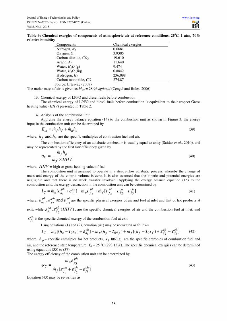
Journal of Energy Technologies and Policy www.iiste.org
ISSN 2224-3232 (Paper) ISSN 2225-0573 (Online)
Vol.5, No.1, 2015
38
Table 3: Chemical exergies of components of atmospheric air at reference conditions, 250C, 1 atm, 70%
relative humidity
Components Chemical exergies
Nitrogen, N2 0.6681
Oxygen, O2 3.9305
Carbon dioxide, CO2 19.610
Argon, Ar 11.640
Water, H2O (g) 9.474
Water, H2O (liq) 0.8842
Hydrogen, H2 236.098
Carbon monoxide, CO 274.87
Source: Ertesvag (2007)
The molar mass of air is given as Mair = 28.96 kg/kmol (Cengel and Boles, 2006).
13. Chemical exergy of LPFO and diesel fuels before combustion
The chemical exergy of LPFO and diesel fuels before combustion is equivalent to their respect Gross
heating value (HHV) presented in Table 2.
14. Analysis of the combustion unit
Applying the energy balance equation (14) to the combustion unit as shown in Figure 3, the energy
input in the combustion unit can be determined by
aaffin hmhmE ɺɺ += (39)
where, af hh and are the specific enthalpies of combustion fuel and air.
The combustion efficiency of an adiabatic combustor is usually equal to unity (Saidur et al., 2010), and
may be represented by the first law efficiency given by
HHVm
hm
f
ppC
×=ɺ
ɺ
η (40)
where, HHV = high or gross heating value of fuel
The combustion unit is assumed to operate in a steady-flow adiabatic process, whereby the change of
mass and energy of the control volume is zero. It is also assumed that the kinetic and potential energies are
negligible and that there is no work transfer involved. Applying the exergy balance equation (15) to the
combustion unit, the exergy destruction in the combustion unit can be determined by
][][322311
chf
chf
ph
ffph
ppcha
ph
aaC mmmI εεεεεε −++−+= ɺɺɺɺ (41)
where, ph
p
ph
f
ph
a 321 and , εεε are the specific physical exergies of air and fuel at inlet and that of hot products at
exit, while cha1
ε , )(2
HHVchfε , are the specific chemical exergies of air and the combustion fuel at inlet, and
chf3
ε is the specific chemical exergy of the combustion fuel at exit.
Usng equations (1) and (2), equation (41) may be re-written as follows
])[()(])[(321 000
chf
chffffppp
chaaaaC sThmsThmsThmI εεε −+−+−−+−= ɺɺɺɺ (42)
where, ph = specific enthalpies for hot products, af ss and are the specific entropies of combustion fuel and
air, and the reference state temperature, T0 = 25 0C (298.15 K). The specific chemical exergies can be determined
using equations (35) to (37).
The exergy efficiency of the combustion unit can be determined by
][
322
3
chf
chf
ph
ff
ph
pp
Cm
m
εεε
εψ
−+=ɺ
ɺ
(43)
Equation (43) may be re-written as
Journal of Energy Technologies and Policy www.iiste.org
ISSN 2224-3232 (Paper) ISSN 2225-0573 (Online)
Vol.5, No.1, 2015
39
])[(
)(
320
0
chf
chffff
pppC
sThm
sThm
εεψ
−+−
−=ɺ
ɺ
(44)
15. Analysis of the heat exchanging unit
Performing an energy balance on the heat exchanging unit as shown in Figure 3, and noting that
gp mm ɺɺ = and sw mm ɺɺ = , the heat loss can be determined by
)()()( wswgpplossH hhmhhmQ −−−= ɺɺ (45)
where, wsg hhh and , are the specific enthalpies of exhaust flue gas, steam and feed water.
The first law efficiency of the heat exchanging unit can be determined by (Saidur et al., 2010)
)(
)(
gpp
wswH
hhm
hhm
−
−=ɺ
ɺη (46)
The exergy destruction in the heat exchanging unit can be determined by
][][][6655443
chg
ph
ggchs
ph
sschw
ph
wwph
ppH mmmmI εεεεεεε +−+−++= ɺɺɺɺɺ (47)
where, , and ,,6543
ph
g
ph
s
ph
w
ph
pεεεε are the specific physical exergies of products of combustion, feed water,
steam and exhaust flue gas, while chg
chs
chw 654
and , εεε are the chemical exergies of the feed water, steam and
exhaust flue gases, The specific chemical exergies of steam and liquid water are respectively given as 526.33
kJ/kg (9474 kJ/kmol) and 49.12 kJ/kg (884.20 kJ/kmol) (Ertesvag, 2007, Szargut et al., 2011, Talens, et al., 2007).
Equation (47) may be re-written as
])[(])[(
])[()(
65
4
00
00
chgggg
chssss
chwwwwpppH
sThmsThm
sThmsThmI
εε
ε
+−−+−−
+−+−=
ɺɺ
ɺɺɺ
(48)
where, wsg sss and , are the specific entropies of exhaust flue gas, steam and feed water.
The exergy efficiency of the heat exchanging unit can be determined by
)][
][][
663
4455
chg
ph
ggph
pp
chw
ph
wwchs
ph
ss
Hmm
mm
εεε
εεεεψ
+−
+−+=
ɺɺ
ɺɺ
(49)
Equation (49) may be re-written as
)])[()(
])[(])[(
6
45
00
00
chggggppp
chwwww
chssss
HsThmsThm
sThmsThm
ε
εεψ
+−−−
+−−+−=
ɺɺ
ɺɺ
(50)
16. Analysis of the entire boiler
The overall boiler energy efficiency can be determined by (Saidur et al., 2010)
ff
wssB
hm
hhm
ɺ
ɺ )( −=η (51)
The overall exergy destruction of the boiler was obtained as the sum of exergy destruction in the combustion
chamber and the heat exchanger. That is,
HCB III ɺɺɺ += (52)
The overall boiler exergy efficiency can be determined as the rational efficiency of the entire boiler which is the
ratio of the desired exergy output, tputdesired ouEɺ to the exergy used, usedEɺ (Cornelissen, 1997). The
tputdesired ouEɺ was the net exergy for the transformation of water, while usedEɺ was the net energy input into
the system. The exergy efficiency of the boiler can therefore be determined by
Journal of Energy Technologies and Policy www.iiste.org
ISSN 2224-3232 (Paper) ISSN 2225-0573 (Online)
Vol.5, No.1, 2015
40
used
tputdesired ouB
E
E
ɺ
ɺ
=ψ (53)
Equation (53) may be expressed as
][
][
32
4545
2chf
chf
phff
chw
chs
ph
w
ph
ss
Bm
m
εεε
εεεεψ
−+
−+−=
ɺ
ɺ
(54)
])[(
])()[(
32
45
0
00
chf
chffff
chw
chswwsss
BsThm
sThsThm
εε
εεψ
−+−
−+−−−=
ɺ
ɺ
(55)
4. Conclusion
The framework to evaluate thermodynamic properties and performance variables associated with material
streams in steam boilers as presented in this study would afford researchers with a broad base of alternatives in
analysing and determining vital parameters needed in an energy and exegy analysis of steam boilers. The
framework offers advanced thermodynamic solutions based on first principles to determine mass flow rate,
temperatures, enthalpies and entropies which could be used to obtain performance indices, resources allocation,
areas and magnitude of energy losses and exergy destruction.
Instructors, researchers and advanced students of engineering, sciences and energy analysis are
expected to find this material as a helpful tool to quickly understand fundamental concepts and approach
required in energy and exergy analysis of industrial plants. A number of information that is not commonly
contained in a single text or in a simplified manner has been elaborated in this methodology with worked
examples presented in the appendix. Furthermore, the framework does not in any way place a limit on its users,
on the contrary, users would interestingly discover a divergent and varied alternatives to tackling and solving
problems related to energy and exergy analysis in diversified circumstances. Also, users could find the
framework as a good starting point for modelling and simulation of energy and exergy related solutions of
industrial plants and facilities.
References
1. Aljundi, I. H. (2009), Energy and Exergy Analysis of a Steam Power Plant in Jordan, Applied Thermal
Engineering, Vol. 29, pp324–328.
2. Armstrong (2010), Specific Heat-Specific Gravity, [online]. Available:
www.armstronginternational.com/files/common/allproductscatalog/cg-53.pdf (November 15, 2010,)
3. Ayhan, B. and Demirtas, C. (2001), Investigation of Turbulators for Fire Tube Boilers Using Exergy Analysis,
Turk J Engin Environ Sci, TUBITAK Vol. 25, pp249-258.
4, Bureau of Energy Efficiency (2010a), Boilers: Types, Combustion in boilers, Performances evaluation,
Analysis of losses, Feed water treatment, Blow down, Energy conservation opportunities, [online].
Available: emt-india.com/BEE-Exam/GuideBooks/2Ch2.pdf (October 19, 2010)
5. Bureau of Energy Efficiency (2010b), Energy Performance Assessment of Boilers, [online]. Available:
www.em-ea.org/Guide Books/book-4/4.1Boiler.pdf (December 9, 2010)
6. Cengel, Y. A. and Boles, M. A. (2006), Thermodynamics: An Engineering Approach, 5th
Edition, McGraw
Hill.
7. Chemical Exergy (2011), Lecture 7.5 [online].
Available: www.oocities.org/pldhar/Lecture 7_5.ppt (July 4, 2011],)
8. Cornelissen, R. L. (1997), Thermodynamics and Sustainable Development-The Use of Exergy Analysis and
the Reduction of Irreversibility, Enschede, The Netherlands, pp2-5, 11-14.
9. Dincer, I. Hussain, M. M. and Al-Zaharnah, I. (2003), Energy and Exergy Use in the Industrial Sector of
Saudi Arabia, Proc. Instn. Mech. Engrs., Vol. 217, pp481-492. Part A: J. Power and Energy, A02603 IMechE.
10. Dincer, I. and Rosen, M. A. (2007), Exergy: Energy, Environment and Sustainable Development, Elsevier,
London.
11. ETSAP (Energy Technology Systems Analysis Programme) (2010), Industrial Combustion Boilers, IEA
ETSAP-Technology Brief 101-May 2010, Available: www.etsap.org
12. Ertesvag, I. S. (2007), Sensitivity of the Chemical Exergy for Atmospheric Gases and Gaseous Fuels to
Variations in Ambient Conditions, Energy Conservation and Management, Vol. 48, pp1983-1995.
13. Jorge Luis Hau, M.S. (2005), Toward Environmentally Conscious Process Systems Engineering Via Joint
Thermodynamic Accounting of Industrial and Ecological Systems, Doctor of Philosophy Dissertation, Ohio

Journal of Energy Technologies and Policy www.iiste.org
ISSN 2224-3232 (Paper) ISSN 2225-0573 (Online)
Vol.5, No.1, 2015
41
State University, USA.
14. Kitto, J. B. and Stultz, S. C. (2005), Steam: Its Generation and Use (2005), 41st edition, The Babcock and
Wilcox Company, Barberton, Ohio, U.S.A.
15. Modesto, M. and Nebra, S. A. (2009), Exergoeconomic Analysis of the Power Generation System Using
Blast Furnace and Coke Oven Gas in a Brazillian SteelMill, Applied Thermal Engineering, Vol. 29, pp2127-
2136.
16. Ohijeagbon, I. O. (2012), Life Cycle Energetic Analysis of Steam Boilers Operation in Selected Production
Industries, Ph.D. Thesis, Department of Mechanical Engineering, Ladoke Akintola University of Technology,
Ogbomoso, Nigeria.
17. Osemene, K. P. (2008), Evaluation of Herbal Medicines Research and Development Outputs in Nigeria, A
Ph.D Proposal in Technology Planning and DevelopmentUnit, Obafemi Awolowo University, Ile Ife.
18. Petroleum (2011), [online]. Available: http://www.middleeastoil.net/Petroleum.pdf (February 14, 2011)
19. Process Heating (2010), Combustion Efficiency, [online]. Available:www.docstoc.com/docs/.../Process-
Heating--Combustion-Efficiency (October 14, 2010)
20. Rajput, R. K. (2006), Thermal Engineering, Laxmi Publications (P) Ltd., New Delhi.
21. Roger, G. F. C. and Mayhew, Y. R. (1992), Engineering Thermodynamics: Work and Heat Transfer,
Longman Group Limited, 4th
Edition, UK.
22. Saidur, R., Ahamed, J. U. and Masjuki, H. H. (2010), Energy, Exergy and Economic Analysis of Industrial
Boilers, Energy Policy, Vol. 38 pp2188–2197.
23. Szargut, J., Valero, A., Stanek, W. and Valero, A. (2011), Towards an International Reference
Environment of Chemical Exergy [online]. Available: www.exergoecology.com/papers/towards_int_re.pdf (May
20, 2011)
24. Talens, L., Villalba, G. and Gabarrell, X. (2007), Exergy Analysis Applied to Biodiesel Production, Elsevier
(Resources, Conservation and Recycling), Vol. 51, pp397-407.
25. Tonon, S., Brown, M. T., Luchic, F., Mirandola, A., Stoppato, A., and Ulgiati, S. (2006), An Integrated
Assessment of Energy Conversion Processes By Means of Thermodynamic, Economic And Environmental
Parameters, Energy Vol. 31, pp149-163.
26. TSI Incorporated (2004), Combustion Analysis Basics: An Overview of Measurements, Methods and
Calculations Used in Combustion Analysis, Available: www.tsi.com
27. Turns, S. R. and Kraige, D. R. (2007), Property Tables for Thermofluids Engineering, Cambridge University
Press, UK.
28. United Nations Environment Programme (UNEP) (2010). Division of Technology, Industry and Economics,
Energy Efficiency Guide for Industry in Asia [online]. Available:
www.greenbiz.com/sites/default/files/document/CustomO16C45F67124.pdf (October 20, 2010)
Appendix: Worked Examples
Preliminary computed mass flow rates of material streams in a boiler using previous mass balance equations are
presented in Appendix Table 1. Some other properties, such as temperatures, enthalpies and entropies which
may not be easily measured or determined directly from a boiler were therefore obtained using earlier derived
thermodynamic, energy and exergy equations respectively as presented in Appendix Table 1.
Appendix Table 1: Computed thermodynamic properties of materials streams in a boiler using
LPFO
Point Substances Mass flow rate
(kg/s)
Temperature
(0C)
Enthalpy
(kJ/kg)
Entropy
(kJ/kgK)
1 Air, amɺ , 3.3744 80.63 354.53 1.8684
2 Fuel, fmɺ 0.2109 1,084.82 40,515.15 2.0009
3 Hot products, pmɺ 3.5853 275.73 2,716.92 4.9513
4 Feed water, wmɺ 2.5308 100.00 419.10 1.3070
5 Steam, smɺ 2.5308 168.89 2,767.60 6.6759
6 Exhaust flue gas, gmɺ 3.5853 152.95 231.00 2.0516
Source: Ohijeagbon (2012)
Journal of Energy Technologies and Policy www.iiste.org
ISSN 2224-3232 (Paper) ISSN 2225-0573 (Online)
Vol.5, No.1, 2015
42
1. Combustion temperatures
Using equation (22) and the data stated as follows:
at cp = 1.866 kJ/kg K, AAF = 16, Tca = 80.63 0C, hr(LPFO) = 40,515.15 kJ/kg
The combustion temperature of a boiler operation was calculated as
CAAFc
hTTT
p
rcacf
082.084,1)]161(866.1[
15.515,4063.80
)]1([=
+×+=
+×+==
2. Enthalpy of hot products
The enthalpy of the hot products can be determined using equation (24) and data from Appendix Table
1 as follows;
kgkJhp / 92.716,25853.3
53.3543744.315.515,402109.0=
×+×=
3. Temperature of exhaust flue gases
The benchmark combustion efficiency for various fuels, are give as: coal 90.3%, oil residual 89.6%, oil
distillate 88.7%, natural Gas 85.7% (ETSAP, 2010). Hence,
%6.89)(
=LPFOcombη , HHV(LPFO) = 42,657.34 kJ/kg, AAF(LPFO) = 16, CkgkJc
LPFOp0 /866.1
)(=
The temperature of exhaust flue gases can be determined using equation (26) and data from Appendix
Table 1 as follows;
CTg0 95.152273
866.1)161(
896.034.657,4282.084,1 =
−
×+
×−=
4. Enthalpy of exhaust flue gases
Equation (27) was used to evaluate the enthalpy of the exhaust flue gases from previously calculated
data with the aid of the Microsoft excel spread sheet (inter-conversions were necessary) and is presented as
shown in Appendix Table 1.
5. Entropy of combustion fuel gases
The entropy of combustion fuel gases can be determined using equation (28) and data from Appendix
Table 1 as follows;
kgKkJs f / 0009.282.357,1
92.716,2==
6. Entropy of hot products
The entropy of hot products can be determined using equation (30) and data from Appendix Table 1 as
follows;
kgKkJs p / 9513.473.548
92.716,2==
7. Entropy of exhaust flue gases
At KkgkJsKT aa / 29559.1 , 200 == (Cengel and Boles, 2006)
The entropy of exhaust flue gases can be determined using equation (32) and data from Appendix Table
1 as follows;
KkgkJsg / 0516.2200
)27395.152(ln129559.1 =
+×+=
8. Chemical exergy of air
The molar chemical exergy of atmospheric air can be determined using equation (38) and data from
Tables 1 and 3 as follows;

Journal of Energy Technologies and Policy www.iiste.org
ISSN 2224-3232 (Paper) ISSN 2225-0573 (Online)
Vol.5, No.1, 2015
43
( )
kmolkJ
eneair
chxi
chairx i
/ 65.1702
)]098.236(0001.0)00.610,19(0003.0)00.640,11(0091.0
)00.474,9(0303.0)50.930,3(2035.0)10.666(7565.0[
)(
=
+++
++=
=∑
The molar mass of air is given as Mair = 28.96 kg/kmol (Cengel and Boles, 2006). Hence, the specific chemical
exergy of atmospheric air can be determined using equation (37) as follows;
kgkJch
a / 79.5896.28
65.1702==ε
9. Chemical exergy of LPFO before combustion
The chemical exergy of LPFO before combustion is equivalent to their respect Gross heating value
(HHV) as shown in Table 2 as follows;
kgkJLPFOch
f / 42,657.34)( =ε
10. Chemical exergy of LPFO during combustion
The standard Gibbs functions of formation of other components in equation (36) are given as follows
(Roger and Mayhew, 1992):
2COg = -394,390 kJ/kmol
)(2 vOHg = -228,590 kJ/kmol
2Og = 0
The mole fraction of oxygen (2On ), carbon dioxide (
2COn ) and water ( OHn2
) in a standard
environment are obtained from Table 1 as follows:
2On = 0.2035
2COn = 0.0003
OHn2
= 0.0303
Temperature, T0 = 298.15 K for a standard reference environment (Table 1)
The molar mass of LPFO was estimated as 203.86 kg/kmol from properties and specifications of
selected fuels, and their chemical formula which was estimated as 3.2588.14 HC (TSI Incorporated, 2004,
Cengel, 2006). The standard Gibbs functions of formation for LPFO can be determined by equation (36) as
follows;
kmolkJ
g
/70.186,760,8
0)4
3.2588.14()590,228(
2
3.25)390,394(88.14
−=
×+−−×+−×=∆∴
The molar chemical exergy of LPFO can be determined using equation (35) as follows;
kmolkJ
echfuelx
/82.359,085,9
0303.00003.0
2035.0ln15.2983144.8)70.186,760,8(
)2
3.25(88.14
)4
3.2588.14(
=
×
××+−−=
+
The specific chemical exergy of LPFO can be determined using equation (37) as follows;
Journal of Energy Technologies and Policy www.iiste.org
ISSN 2224-3232 (Paper) ISSN 2225-0573 (Online)
Vol.5, No.1, 2015
44
kgkJM
eLPFO
LPFO
f
f
ch
xch
f /66.566,4486.203
82.359,085,9)(
)(
)(
===ε
11. Chemical exergy of steam and liquid water
The specific chemical exergies of steam ( chsε ) and liquid water (
chwε ), are respectively given as
526.33 kJ/kg (9474 kJ/kmol) and 49.12 kJ/kg (884.20 kJ/kmol) (Ertesvag, 2007, Szargut et al., 2011, Talens, et
al., 2007). kgkJch
w / 12.49 =ε
kJ/kgch
s 526.33 =ε
12. Chemical exergy of exhaust flue gases
The chemical exergy of exhaust flue gases was determined from the mole fractions of the products of
combustion presented in Appendix Table 2, their respective chemical exergies given by Ertesvag (2007) as
shown in Table 3 and the associated carbon monoxide determined by equation (12) as follows;
%336.0)2.01(
2.0212)2.01(668.32)(% =
+
××−+××=pCO
Appendix Table 2: Ultimate and proximate analysis of the products of combustion for complete
combustion of LPFO
Product Mass of Wet Flue
Gas
(kg/kg of Oil)
Mass of Dry Flue
Gas
(kg/kg of Oil)
Ultimate Analysis (%) Proximate Analysis (%)
Wet Dry Wet Dry
CO2 3.2080 3.2080 18.740 19.780 12.4840 13.6430
H2O 0.8928 - 5.220 - 8.4940 -
SO2 0.0280 0.0280 0.164 0.173 0.0754 0.0823
O2 0.6263 0.6263 3.660 3.860 3.3570 3.6680
N2 12.3600 12.3600 72.220 76.190 75.590 82.6070
17.1151 16.2223 100.00 100.00 100.00 100.00
Source: Ohijeagbon (2012)
Hence, the molar chemical exergy of exhaust flue gases was determined as follows;
( )
kmolkJ
eneg
chxi
chgx i
/ 36.350,4
]9598.435035[100
1
)]87.274(336.0)10.668(590.75)50.930,3(3570.3
)00.600,609(0754.0)474,9(4940.8)610,19(4840.12[100
1
100
1)(
=
=
+++
++=
= ∑
The molar mass of the exhaust gas from the combustion of LPFO was also determined from the mole
fractions of the products of combustion and the respective molar masses of each constituent member contained
in the gas as shown in Appendix Table 2.
The molar mass of the exhaust flue gases was determined as follows;

Journal of Energy Technologies and Policy www.iiste.org
ISSN 2224-3232 (Paper) ISSN 2225-0573 (Online)
Vol.5, No.1, 2015
45
( )
kmolkg
MnMLPFOgiig LPFO
/ 40.29
]3656.2940[100
1
)]28(336.0)28(590.75)32(3570.3
)64(0754.0)18(4940.8)44(4840.12[100
1
)()(
=
=
+++
++=
=∑
The specific chemical exergy of the exhaust flue gases can be determined using equation (37) as follows;
kgkJM
e
LPFO
g
g
chxch
g / 97.14740.29
36.350,4
)(
)(
6===∴ε
13. Computation of energy and exergy values and efficiencies
The energy and exergy values of the flow processes in the investigated boilers which include the
physical and chemical exergies were computed using the theoretical procedures given by equations (39) to (55)
and previously computed thermodynamic properties of materials streams data given by Appendix Table 1 and
are presented in Appendix Table 3 to 5. These comprise of exergetic computations in the combustion unit, heat
exchanging unit and the entire boiler accordingly. The method used for the energy and exergy assessment of the
boilers are summarised in Appendix Table 3 to 5. These includes evaluation of energy input, energy efficiency,
exergy destruction and efficiency of the combustion unit; heat loss, energy efficiency, exergy destruction and
efficiency of the heat exchanging unit; energy efficiency, overall exergy destruction and efficiency of the entire
boiler.
Appendix Table 3: Summary of exergetic parameters of combustion unit
Exergetic equations Exergetic Values and Efficiencies
1. Energy input (kJ/s)
aaffin hmhmE ɺɺ +=
9740.97
2. Adiabatic energy efficiency (%)
HHVm
hm
f
ppC
×=ɺ
ɺ
η
100.00
3. Exergy destruction (kJ/s)
])[(
)(])[(
32
1
0
00chf
chffff
pppchaaaaC
sThm
sThmsThmI
εε
ε
−+−+
−−+−=
ɺ
ɺɺɺ
3103.92
4. Exergy efficiency (%)
])[(
)(
320
0
chf
chffff
pppC
sThm
sThm
εεψ
−+−
−=ɺ
ɺ
55.35
Journal of Energy Technologies and Policy www.iiste.org
ISSN 2224-3232 (Paper) ISSN 2225-0573 (Online)
Vol.5, No.1, 2015
46
Appendix Table 4: Summary of exergetic parameters of heat exchanging unit
Exergetic equations Exergetic Values and Efficiencies
1. Heat loss (kJ/s)
)()()( wswgpplossH hhmhhmQ −−−= ɺɺ
2969.19
2. Energy efficiency (%)
)(
)(
gpp
wswH
hhm
hhm
−
−=ɺ
ɺη
66.69
3. Exergy destruction (kJ/s)
])[(])[(
])[()(
65
4
00
00chgggg
chssss
chwwwwpppH
sThmsThm
sThmsThmI
εε
ε
+−−+−−
+−+−=
ɺɺ
ɺɺɺ
2182.44
4. Exergy efficiency (%)
)])[()(
])[(])[(
6
45
00
00
chggggppp
chwwww
chssss
HsThmsThm
sThmsThm
ε
εεψ
+−−−
+−−+−=
ɺɺ
ɺɺ
58.69

Journal of Energy Technologies and Policy www.iiste.org
ISSN 2224-3232 (Paper) ISSN 2225-0573 (Online)
Vol.5, No.1, 2015
47
Appendix Table 5: Summary of exergetic parameters of entire boiler
Exergetic equations Exergetic Values and Efficiencies
1. Energy efficiency (%)
ff
wssB
hm
hhm
ɺ
ɺ )( −=η
69.56
2. Overall exergy destruction (kJ/s)
HCB III ɺɺɺ +=
5286.35
3. Overall exergy efficiency (%)
])[(
])()[(
32
45
0
00
chf
chffff
chw
chswwsss
BsThm
sThsThm
εε
εεψ
−+−
−+−−−=
ɺ
ɺ
38.57

The IISTE is a pioneer in the Open-Access hosting service and academic event management.
The aim of the firm is Accelerating Global Knowledge Sharing.
More information about the firm can be found on the homepage:
http://www.iiste.org
CALL FOR JOURNAL PAPERS
There are more than 30 peer-reviewed academic journals hosted under the hosting platform.
Prospective authors of journals can find the submission instruction on the following
page: http://www.iiste.org/journals/ All the journals articles are available online to the
readers all over the world without financial, legal, or technical barriers other than those
inseparable from gaining access to the internet itself. Paper version of the journals is also
available upon request of readers and authors.
MORE RESOURCES
Book publication information: http://www.iiste.org/book/
Academic conference: http://www.iiste.org/conference/upcoming-conferences-call-for-paper/
IISTE Knowledge Sharing Partners
EBSCO, Index Copernicus, Ulrich's Periodicals Directory, JournalTOCS, PKP Open
Archives Harvester, Bielefeld Academic Search Engine, Elektronische Zeitschriftenbibliothek
EZB, Open J-Gate, OCLC WorldCat, Universe Digtial Library , NewJour, Google Scholar