Embed Size (px)
Citation preview

Part Number 550-110-752/0402
Contents Page
1 Prepare boiler location ........................................................ 2
2 Prepare boiler ..................................................................... 5
3 Connect breeching ............................................................. 6
4 Connect steam piping ......................................................... 7
5 Connect tankless heater piping, if used ............................ 10
6 Connect wiring .................................................................. 11
7 Connect oil piping ............................................................. 14
8 Start-up ............................................................................ 15
9 Checkout procedure ......................................................... 16
10 Service and maintenance ................................................. 18
11 Replacement parts ........................................................... 22
12 Dimensions ...................................................................... 26
13 Ratings ............................................................................. 27
Boiler Manual
This manual must only be used by a qualified heating installer/service technician. Boiler and burner must be installedand serviced only by a qualified heating installer/service technician. Failure to comply could result in severe personal injury,death or substantial property damage.
When calling or writing about the boiler— Please have: • boiler model number from the boiler rating label and • CP numberfrom the boiler jacket. You may list the CP number in the space provided on the “Installation and service certificate” found onpage 17.
Hazards that will or can cause minor personal injuryor property damage.
Special instructions on installation, operation ormaintenance that are important but not related topersonal injury or property damage.
INSTALLER — Read all instructions beforeinstalling. Read page 2 first. Follow all instructionsin proper order to prevent personal injury or death.
• Consider piping and installation when determiningboiler location.
• Any claims for damage or shortage in shipmentmust be filed immediately against the transportationcompany by the consignee.
USER — Please read the following. Failure tocomply could result in severe personal injury, deathor substantial property damage.
• This manual is for use only by your qualifiedheating installer/service technician.
• Please see the User’s Information Manual for yourreference.
• Have the boiler serviced by a qualified servicetechnician, at least annually.
Hazards that will cause severe personal injury,death or substantial property damage.
Hazards that can cause severe personal injury,death or substantial property damage.
Hazard definitions
Oil-Fired Steam Boilers

OSB Oil-Fired Steam Boilers – Boiler Manual
2 Part Number 550-110-752/0402
Installations must follow these codes:• Local, state, provincial, and national codes, laws, regulations
and ordinances.• NFPA-31, Installation of Oil-Burning Equipment.• Standard for Controls and Safety Devices for Automatically
Fired Boilers, ANSI/ASME CSD-1, when required.• National Electrical Code.
Certification
Codes & checklistFailure to adhere to the guidelines below canresult in severe personal injury, death orsubstantial property damage.
When servicing boiler —1. To avoid electric shock, disconnect electrical supply
before performing maintenance.2. To avoid severe burns, allow boiler to cool before
performing maintenance.
Boiler operation —3. Do not block flow of combustion or ventilation air to boiler.4. Should overheating occur, turn off or disconnect electrical
supply to boiler and shut off the oil supply at a locationexternal to the appliance, if possible.
5. Do not use this boiler if any part has been under water.Immediately call a qualified service technician to inspectthe boiler and to replace any part of the control systemand any burner control that has been under water.
Boiler water —6. DO NOT use petroleum-based cleaning or sealing
compounds in boiler system. Water seal deterioration willoccur, causing leakage between boiler sections, circulatorflanges, diaphragm tanks or other system components.This can result in substantial property damage.
7. DO NOT use "homemade cures" or "boiler patentmedicines". Serious damage to boiler, personnel and/orproperty may result.
8. Continual fresh makeup water will reduce boiler life. Mineralbuildup in sections reduces heat transfer, overheats castiron, and causes section failure. Addition of oxygen andother gases can cause internal corrosion. Leaks in boileror piping must be repaired at once to prevent makeupwater.
9. Do not add cold water to hot boiler. Thermal shock cancause sections to crack.
1 Prepare boiler locationRead this first!
The OSB boiler burner and controls met safe lightingand other performance criteria when boiler underwenttests specified in CSA B140.0 and B140.7.1.
Before locating the boiler:
❏ Check for nearby connection to:• Makeup water and steam piping• Venting connections (page 6)• Combustion and ventilation air provisions (page 4)• Oil supply piping (page 14 and burner manual)• Electrical power
❏ Check area around boiler. Remove any combustible materials,gasoline and other flammable liquids.
Failure to keep boiler area clear and free ofcombustible materials, gasoline and other flammableliquids and vapors can result in severe personalinjury, death or substantial property damage.
❏ Boiler must be installed so that burner and control systemcomponents are protected from dripping or spraying water orrain during operation or service.
❏ If new boiler will replace existing boiler, check for and correctsystem problems, such as system leaks causing oxygencorrosion or section cracks from hard water deposits.

3Part Number 550-110-752/0402
OSB Oil-Fired Steam Boilers – Boiler Manual
1 Prepare boiler location continued
Minimum clearance to combustible materials1. Minimum clearances from vent pipe to combustible material (see
Figure 1, vent clearances indicated with “*”):• Type “L” doublewall vent — 6 inches minimum• Singlewall vent — 18 inches minimum
Flue pipe clearances must take precedence overjacket clearances (listed below).
Service clearances1. Recommended service clearances (see Figure 1):
• Front and top — 24 inches• Left side, back and right side — 6 inches• Right side for burner door swing radius — 12 inches.
Clearances Flooring and foundation
FlooringThe OSB boiler is approved for installation on combustible flooring,but must never be installed on carpeting.
Do not install boiler on carpeting even if foundation isused. Fire can result, causing severe personal injury,death or substantial property damage.
Foundation1. Provide a solid brick or minimum 2-inch thick concrete
foundation pad if any of the following is true:• floor can become flooded.• the boiler mounting area is not level.
2. See Table 1 for minimum foundation dimensions.
Residential garage installationsTake the following special precautions when installing the boiler ina residential garage. If the boiler is located in a residential garage:• Mount the boiler a minimum of 18 inches above the floor of the
garage to ensure the burner and ignition devices will be no lessthan 18 inches above the floor.
• Locate or protect the boiler so it cannot be damaged by a movingvehicle.
Table 1 Minimum foundation size
Figure 1 Minimum clearancesBoilermodelnumber
Lengthinches
Widthinches
Minimumheightinches
OSB-3 17 22 2
OSB-4 20 22 2
OSB-5 23 22 2
OSB-6 26 22 2
OSB Oil-Fired Steam Boilers – Boiler Manual
4 Part Number 550-110-752/0402
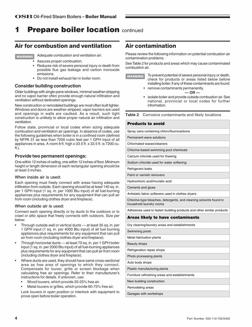
Table 2 Corrosive contaminants and likely locations
To prevent potential of severe personal injury or death,check for products or areas listed below beforeinstalling boiler. If any of these contaminants are found:
• remove contaminants permanently.— OR —
• isolate boiler and provide outside combustion air. Seenational, provincial or local codes for furtherinformation.
Please review the following information on potential combustion aircontamination problems.See Table 2 for products and areas which may cause contaminatedcombustion air.
1 Prepare boiler location continued
Air contaminationAir for combustion and ventilation
Products to avoid
Spray cans containing chloro/fluorocarbons
Permanent wave solutions
Chlorinated waxes/cleaners
Chlorine-based swimming pool chemicals
Calcium chloride used for thawing
Sodium chloride used for water softening
Refrigerant leaks
Paint or varnish removers
Hydrochloric acid/muriatic acid
Cements and glues
Antistatic fabric softeners used in clothes dryers
Chlorine-type bleaches, detergents, and cleaning solvents found in household laundry rooms
Adhesives used to fasten building products and other similar products
Areas likely to have contaminants
Dry cleaning/laundry areas and establishments
Swimming pools
Metal fabrication plants
Beauty shops
Refrigeration repair shops
Photo processing plants
Auto body shops
Plastic manufacturing plants
Furniture refinishing areas and establishments
New building construction
Remodeling areas
Garages with workshops
Adequate combustion and ventilation air:
• Assures proper combustion.• Reduces risk of severe personal injury or death from
possible flue gas leakage and carbon monoxideemissions.
• Do not install exhaust fan in boiler room.
Consider building constructionOlder buildings with single-pane windows, minimal weather-strippingand no vapor barrier often provide enough natural infiltration andventilation without dedicated openings.New construction or remodeled buildings are most often built tighter.Windows and doors are weather-stripped, vapor barriers are usedand openings in walls are caulked. As a result, such tightconstruction is unlikely to allow proper natural air infiltration andventilation.Follow state, provincial or local codes when sizing adequatecombustion and ventilation air openings. In absence of codes, usethe following guidelines when boiler is in a confined room (definedby NFPA 31 as less than 7200 cubic feet per 1 GPH input of allappliances in area. A room 8 ft. high x 33.5 ft. x 33.5 ft. is 7200 cu.ft.).
Provide two permanent openings:One within 12 inches of ceiling, one within 12 inches of floor. Minimumheight or length dimension of each rectangular opening should beat least 3 inches.
When inside air is used:Each opening must freely connect with areas having adequateinfiltration from outside. Each opening should be at least 140 sq. in.per 1 GPH input (1 sq. in. per 1000 Btu input) of all fuel-burningappliances plus requirements for any equipment that can pull airfrom room (including clothes dryer and fireplace).
When outside air is used:Connect each opening directly or by ducts to the outdoors or tocrawl or attic space that freely connects with outdoors. Size perbelow:• Through outside wall or vertical ducts — at least 35 sq. in. per
1 GPH input (1 sq. in. per 4000 Btu input) of all fuel burningappliances plus requirements for any equipment that can pullair from room (including clothes dryer and fireplace).
• Through horizontal ducts — at least 70 sq. in. per 1 GPH boilerinput (1 sq. in. per 2000 Btu input) of all fuel-burning appliancesplus requirements for any equipment that can pull air from room(including clothes dryer and fireplace).
• Where ducts are used, they should have same cross-sectionalarea as free area of openings to which they connect.Compensate for louver, grille or screen blockage whencalculating free air openings. Refer to their manufacturer’sinstructions for details. If unknown, use:• Wood louvers, which provide 20-25% free air.• Metal louvers or grilles, which provide 60-75% free air.Lock louvers in open position or interlock with equipment toprove open before boiler operation.

5Part Number 550-110-752/0402
OSB Oil-Fired Steam Boilers – Boiler Manual
2 Prepare boiler
Hydrostatic pressure test1. Remove steam pressure gauge furnished with boiler. Install
water pressure gauge for test only. Be sure gauge can handletest pressure.
2. Install air vent in tapping on top of boiler.3. Remove pressure control and low water cutoff. Plug tappings.4. Plug supply and return tappings.5. Drain valve is already factory-installed.6. Fill boiler. Vent all air. Pressure test boiler at 45-55 psig.
Do not leave boiler unattended. Cold water fill canexpand and damage cast iron, resulting in severepersonal injury, death or substantial property damage.
7. Check for maintained gauge pressure for more than 10 minutes.Visually check for leaks if gauge pressure drops.
8. Drain boiler. Repair leaks if found.Using petroleum-based compounds to repair leakscan damage system components, resulting inproperty damage.
9. Retest boiler after repairing leaks.10. Remove pressure gauge, air vent and plugs. Reinstall steam
pressure gauge, pressure control and low water cutoff furnishedwith boiler.
Tankless heater, if used1. Remove tankless heater knockout in left side of jacket panel.2. Remove tankless heater cover plate and gasket.3. Install new gasket and tankless heater over studs around
opening. Secure with 3/8" nuts.4. Install tankless heater operating control in tapping in tankless
heater. If not furnished, use operating control with maximum10 °F differential.
Place boiler
The boiler contains ceramic fiber and fiberglassmaterials. Use care when handling these materialsper instructions on page 28 of this manual. Failureto comply could result in severe personal injury.
1. Remove boiler from pallet.Do not drop boiler or bump jacket or burner on flooror pallet. Damage to boiler or burner can result.
Smaller sized boilers may be top heavy. Use cautionwhen handling to avoid minor personal injury orproperty damage.
2. Check level. Shim legs if needed.
3. Open burner mounting door. Verify that chamber ceramic lineris securely in place on target wall, chamber floor and burnerdoor. Verify door seal is intact and in place. Close and securelybolt the door.
4. Visually check:a. Flue collector hood seal.b. Burner mounting door seal.
Obtain gas-tight seal to prevent possible flue gasleakage and carbon monoxide emissions, which canlead to severe personal injury or death.

OSB Oil-Fired Steam Boilers – Boiler Manual
6 Part Number 550-110-752/0402
Figure 2 Chimney and breeching connections
Failure to follow all instructions can result in flue gasspillage and carbon monoxide emissions, causingsevere personal injury or death.Inspect existing chimney before installing boiler.Insufficient draft can cause flue gas leakage andcarbon monoxide emissions. Failure to clean orreplace perforated pipe or tile lining and/or patchmortar and joints can cause severe personal injuryor death.
• The OSB boilers are designed to operate with an over-fire draftof -0.01" to -0.02" w.c. Proper draft for these boilers may beachieved using either a conventional chimney (natural draft) ora power vent (sidewall) system that has been properly designedfor use with oil-fired equipment. Power vent manufacturer’sinstructions must be followed.
• Use vent material approved by local codes for oil-fired burners.In their absence, refer to:• NFPA 31, Installation of Oil-Burning Equipment.• NFPA 211, Standard for Chimneys, Fireplaces, Vents and
Solid Fuel Burning Appliances.• NFPA 211 requires chimney to be lined before connected
to boiler.• To prevent downdrafts, extend chimney at least 3 feet above
highest point where it passes through roof and 2 feet higherthan any portion of building within 10 feet. Increase chimneycross-sectional area and height at least 4% per 1,000 feet abovesea level.
• Provide minimum clearances from vent (flue) pipe to combustiblematerial:• Type “L” doublewall vent — 6 inches minimum• Singlewall vent — 18 inches minimum
• Minimum chimney sizes should be used. See Table 3.Oversized chimneys, outside masonry chimneysand/or derated inputs can result in condensation inchimney.
Connect breechingLong horizontal breechings, excessive number oftees and elbows, or other obstructions restrictingcombustion gas flow can result in possibility ofcondensation, flue gas leakage and carbon monoxideemissions, which can lead to severe personal injuryor death.
1. See Figure 2.2. Connect full-sized breeching when possible. See Table 3.3. Connection must be made above bottom of chimney to avoid
blockage. Breeching must not enter chimney far enough tocause obstruction. Use thimble or slip joint where breechingenters chimney to allow removal for cleaning.
General venting requirements
3 Connect breeching
4. When burner and boiler are properly installed, draft overfire willbe approximately -0.01" to -0.02" W.C. Install barometric controlin breeching, per control manufacturer's instructions, whenexcess draft needs to be relieved or to comply with applicablecodes and regulations. Use draft gauge to adjust proper opening.
5. An induced draft fan for the chimney may be necessary if:• Excessive resistance to flow of combustion gases can be
expected.• Cross-sectional area of chimney is smaller than minimum
recommended.• Chimney height is less than recommended.
Table 3 Chimney and breeching minimum sizes
Boiler modelnumber
Minumum breeching diameter
Note 1
Minimum I=B=R chimney size
Minimum chimney heightRectangle
Note 2Round
OSB-3 5" 8" x 8" 6" 15'
OSB-4 6" 8" x 8" 6" 15'
OSB-5 6" 8" x 8" 6" 15'
OSB-6 7" 8" x 8" 7" 15'
Notes:1. Flue collar on boiler is 7" diameter2. 6¾" x 6¾" inside liner

7Part Number 550-110-752/0402
OSB Oil-Fired Steam Boilers – Boiler Manual
4 Connect steam piping
Table 4 Recommended pipe sizing
GeneralIf installation is to comply with special codes, additional limit controlsmay be required. If installing a float-type low water cutoff, use onlythose devices that can be connected to the boiler gauge glasstappings. Refer to the wiring diagrams on pages 12 and 13 for correctwiring location of additional limit controls.
Near-boiler piping
Relief valveInstall boiler relief valve in the ¾" tapping in the back of the boiler,using the ¾" nipple and elbow supplied in the bag with relief valve.
Follow the steps below to avoid potential severepersonal injury, death or substantial property damage.
• When installing the relief valve, ensure that allconnections, including the valve inlet, are clean andfree from any foreign matter.
• Mount the relief valve only in the vertical position,directly connected to the tapping designated in themanual on top of the boiler.
• Use pipe compound sparingly, or tape, on externalthreads only.
• Do not use a pipe wrench! Use proper type and sizewrench on wrench pads only.During operation, this valve may discharge largeamounts of steam and/or hot water. Therefore, toreduce the potential for bodily injury and propertydamage, a discharge line MUST be installed that:
• Is connected from the outlet to a safe point ofdischarge with no intervening valve.
• Allows complete drainage of both the valve and thedischarge line.
• Is independently supported and securely anchoredso as to avoid applied stress as possible.
• Terminates freely to atmosphere where anydischarge will be clearly visible and is at no risk offreezing.
• Is, over its entire length, of a pipe size equal to orgreater than that of the valve outlet.Use only schedule 40 metal pipe for discharge. (Donot use schedule 80, extra strong or double strongpipe or connections.) DO NOT CAP, PLUG OROTHERWISE OBSTRUCT DISCHARGE PIPEOUTLET! If discharge is piped upward, a condensatedrain must be provided in the elbow below the verticalpipe to prevent condensate from returning into thevalve. Failure to comply with these instructions willcause a dangerous spray of hot water and steamthat would cause severe personal injury or death.
Boiler model number
Riserpipe size (Note 1)
Headerpipe size
"H" (Note 2)
Equalizer pipe size
"J"A B
OSB-3 2 ½" -- 2 ½" 1 ½"
OSB-4 2 ½" -- 2 ½" 1 ½"
OSB-5 2 ½" -- 3" 1 ½"
OSB-6 2 ½" 2 ½" 4" 1 ½"
Notes:1. Based on ASHRAE Fundamentals Handbook recommendations,
allowing ½ oz. pressure drop at 0 psig.2. Based on ASHRAE Fundamentals Handbook recommendations,
allowing 2 oz. pressure drop per 100 feet of pipe at 3.5 psig. Maintain minimum 24" height from waterline to bottom of header. Note Figure 3, showing the special connection required to a counterflow system.
See Figures 4 and 5, page 8, for recommended piping of boilersizes OSB-3, -4 and -5. See Figures 6 and 7, page 8, forrecommended piping of OSB-6 boilers. These pipingrecommendations apply only to connections to parallel-flow one-pipe and two-pipe systems. For counterflow systems, connect boilersupply and return to counterflow system header as shown inFigure 3, below. Table 4, below, gives recommended pipe sizes.
Connecting to counterflow pipingApply the recommended piping in Figures 4 through 7 only whenconnecting to a parallel-flow system. When connecting to acounterflow system, the boiler steam supply must connect into thetop of the counterflow system header, as shown in Figure 3, below.
Figure 3 Connection to counterflow steam piping only(for parallel flow systems, see page 8)
The piping in Figure 3 applies only to the special caseof counterflow steam systems. Refer to page 8 forparallel flow steam systems. See below.

OSB Oil-Fired Steam Boilers – Boiler Manual
8 Part Number 550-110-752/0402
Figure 4 Recommended piping, OSB-3, -4 and -5,piping for parallel-flow systems only
Figure 5 Recommended piping, OSB-3, -4 and -5,piping for parallel-flow systems only
Figure 6 Recommended piping, OSB-6, piping forparallel-flow systems only
Figure 7 Recommended piping, OSB-6, piping forparallel-flow systems only
4 Connect steam piping continued
Float-type low water cutoff — If field installing a float-type low water cutoff, it must be piped only to thegauge glass tappings. See Figure 19 on page 26. Thetappings are spaced 9 7/8" on center. Use only float-type low water cutoffs with quick-connect hookupsthat will provide a low water cutoff point no higherthan 2" above the center of the bottom tapping.

9Part Number 550-110-752/0402
OSB Oil-Fired Steam Boilers – Boiler Manual
4 Connect steam piping continued
Figure 8 Recommended piping for parallel-flowsystems with optional reservoir pipe
Modern steam boilers are designed to steam for less time thanolder, larger boilers. When replacing an older steam boiler the systemcondensate return time may be longer than the steaming time. Thiscould cause the following problems:1. Boilers fitted with an automatic water feed could overfill.2. Units fitted with only a low water cutoff would shut down and
cycle while waiting for condensate to return.Following is a simple method for determining whether or not areservoir pipe is required to lengthen steaming time for a residentialinstallation:1. Disconnect condensate return line at existing boiler.2. Heat boiler and allow to steam for 10 minutes. Turn off boiler.3. Measure length of time from when boiler started to steam to
when condensate begins to return through condensate line.4. Measure length of time from when condensate begins to return
to when it stops returning. Divide this time by 2.5. Add time measured in step 3 to time calculated in step 4. This
sum is the average time required for condensate to return tothe boiler.
6. If this total time is 10 minutes or less, no reservoir pipe is needed.If total time for condensate to return to boiler (from step 5) is morethan 10 minutes, a reservoir pipe (or boiler feed system) isrecommended. See Table 5, this page, for suggested reservoir pipesize. Install as shown in Figures 8 and 9, below.For larger systems (as noted in Table 5), use a boiler feed systemwith a condensate tank and feed pump. You will have to install a lowwater cutoff/pump control on the boiler to operate the pump. See“Low water cutoffs” on page 20 and Figure 19 on page 26. UseTable 6 to size boiler feed systems. (The use of a combinationcondensate tank and float-controlled condensate return pump isnot recommended. These devices do not supply water to the boileron demand from the boiler, and cannot compensate for longcondensate return times.)For most residential installations a reservoir pipe may be all that isnecessary to ensure proper operation.
Condensate return
Figure 9 Recommended piping for parallel-flowsystems with optional reservoir pipe
Table 6 Boiler feed system sizing
Table 5 Reservoir pipe sizing
Boilermodel
number
Boilergrossoutput
Time from initial steaming to average condensate return (boiler steaming capacity based on 970 Btu per
pound of steam)15 minutes 20 minutes 30 minutes
MBH gallonspipe
length (feet)
gallonspipe
length (feet)
gallonspipe
length (feet)
OSB-3-100 100 1 1 2 2
Use boiler feed system
OSB-4-110 110 1¼ 1¼ 2½ 2¼OSB-4-125 125 1¼ 1¼ 2½ 2¼OSB-5-135 135 1½ 1½ 3 2½OSB-5-150 150 1½ 1½ 3 2½OSB-6-175 175 1¾ 1¾
Use boiler feed systemOSB-6-200 200 2 2
Designed full capacity steaming time of modern boilers is 10 minutes.
Boilermodelnumber
I=B=R grossoutput
(pounds steam
per hour)
Conden-sate
(gallonsper hour)
Minimum condensate receiver capacity gallons for boiler
steaming times (minutes) of: (note 1)
Suggested feed pumpcapacity
(GPM@ 15 PSI)
(note 2)15 min. 30 min. 45 min. 60 min.
OSB-3-100 120 14 4 9 13 17 0.5
OSB-4-110 133 16 5 10 14 19 0.5
OSB-4-125 149 18 5 11 16 21 0.6
OSB-5-135 162 19 6 12 18 23 0.6
OSB-5-150 180 22 6 13 19 26 0.7
OSB-6-175 210 25 8 15 23 30 0.8
OSB-6-200 239 29 9 17 26 34 1.0
Notes:1. Maximum time to when condensate returns to boiler.2. If pump exceeds capacity shown, pump can be throttled with globe or ball
valve.

OSB Oil-Fired Steam Boilers – Boiler Manual
10 Part Number 550-110-752/0402
5 Connect tankless heater piping, if used
Figure 10 Piping connections to tankless heater, typical
Hot water can scald!• Consumer Product Safety Commission and some
states recommend domestic hot water temperatureof 130 °F or less.
• When installing an automatic mixing valve, selectionand installation must comply with valve manufacturer’srecommendations and instructions.
• Water heated to a temperature suitable for clotheswashing, dish washing and other sanitizing needswill scald and cause injury.
• Children and elderly, infirm or physically handicappedpersons are more likely to be injured by hot water.Never leave them unattended in or near a bathtub,shower or sink. Never allow small children to use ahot water faucet or draw their own bath. If anyoneusing hot water in the building fits this description, orif state laws or local codes require certain watertemperatures at hot water faucets, take specialprecautions:
• Install automatic mixing valve set according to thosestandards.
• Use lowest practical temperature setting.• Check water temperature immediately after first
heating cycle and after any adjustment.
Studies have indicated that dangerous bacteria canform in potable water distribution systems if certainminimum water temperatures are not maintained.Contact local health department for more information.
Table 7 Tankless heater ratings
These single wall heat exchangers comply withNational Standard Plumbing Code provided that:
• Boiler water (including additives) is practicallynontoxic, having toxicity rating or class of 1, as listedin Clinical Toxicology of Commercial Products.
• Boiler water pressure is limited to maximum 30 psigby approved water relief valve.
Pipe tankless heater1. Size piping no smaller than tankless heater inlet and outlet.2. Following controls (furnished by others) must be installed:
a. Automatic mixing valve. See Figure 10. (Read DANGERstatement at left.)
b. Flow regulating valve (see Figure 10). Size according tointermittent draw of tankless heater. See Table 7. Followvalve manufacturer’s instructions to install.
3. Additional anti-scald devices may be installed at each hot waterfaucet, bath and shower outlet.
4. In hard water areas, soften cold domestic supply water toheaters to prevent lime buildup.
Tankless heater ratings are based on 200°F boilerwater temperature. To get rated output, set tanklessheater control to 200°F. Control can be adjusted tomeet system hot water requirements.
Boiler model number(Note 1)
Heater number
Intermittent draw ratings
(GPM) (Note 2)
Inlet andoutlet
tapping sizes
OSB-3 35-S-29 3.25 ¾"
OSB-4 35-S-29 3.50 ¾"
OSB-5 35-S-29 3.75 ¾"
OSB-6 35-S-29 4.00 ¾"
Notes:1. To avoid supplying steam to system during summer tankless
operation, raise water level to one inch above normal water line.2. Gallons of water per minute heated from 40˚F to 140˚F with 200˚F
boiler water temperature. Tested in accordance with I=W=H testing and Rating Standard for Indirect Tankless Water Heaters Tested with Boilers.

11Part Number 550-110-752/0402
OSB Oil-Fired Steam Boilers – Boiler Manual
6 Connect wiring
Electric shock hazard. Can cause severe personalinjury or death if power source, including serviceswitch on boiler, is not disconnected before installingor servicing.
Installations must follow these codes:• National Electrical Code, ANSI/NFPA 70, latest edition and any
additional national, state or local codes.• Wiring must be N.E.C. Class 1. If original wire as supplied with
boiler must be replaced, type 105 °C wire or equivalent mustbe used. Supply wiring to boiler and additional control wiringmust be 14 gauge or heavier.
• Provide electrical ground at boiler as required by codes.
Thermostat wiring• Install thermostat on inside wall away from influences of drafts,
hot or cold water pipes, lighting fixtures, television, sun rays orfireplaces.
• Follow instructions with thermostat. If it has a heat anticipator,set heat anticipator in thermostat to match power requirementsof equipment connected to it. Boiler wiring diagrams give settingfor standard equipment.
Burner wiring• Burner harness incorporates a disconnect plug, providing a
convenient way to disconnect wiring when burner mounting dooris opened. See Figure 11.
Wiring entrance• The probe low water cutoff enclosure houses electrical
connections for all boiler components.• Boilers have harnesses furnished. See Figure 12, page 12,
(OSB boilers with 801 low water cutoffs) or Figure 13, page 13,(OSB boilers with 450 low water cutoffs) for factory and fieldwiring information.
• All field-installed high voltage wiring must be sheathed in metalconduit.
• Connect incoming line voltage wires as shown in Figure 12 orFigure 13, page 12. Field-install equipment ground wire to greenwire with wire nut.
• Some local codes may require an emergency shut-off switchinstalled at a location away from boiler. Follow local codes.
Figure 11 Electrical components and harnesses

OSB Oil-Fired Steam Boilers – Boiler Manual
12 Part Number 550-110-752/0402
6 Connect wiring continued
Figure 12 Wiring diagram — OSB boilers with 801 low water cutoffs

13Part Number 550-110-752/0402
OSB Oil-Fired Steam Boilers – Boiler Manual
6 Connect wiring continued
Figure 13 Wiring diagram — OSB boilers with 450 low water cutoffs

OSB Oil-Fired Steam Boilers – Boiler Manual
14 Part Number 550-110-752/0402
7 Connect oil piping
General oil piping requirements• Location and installation of oil tanks, oil piping and burners must
follow:• NFPA 31, Standard for the Installation of Oil-Burning
Equipment.• Local codes and regulations.• Information provided with burner and fuel pump.
• If any part of fuel oil tank is above level of burner, an anti-siphondevice must be used to prevent flow of oil in case of oil linebreak.
• Support oil lines as required by codes.• Make tank connections with swing joints or copper tubing to
prevent breaking in case the tank settles. Make swing joints sothey will tighten as tank settles. Non-hardening pipe jointcompounds should be used on all threads.
Do not use Teflon tape as an oil pipe sealant. It cancause valves to fail, creating hazards. Do not usecompression fittings, only flare fittings. Failure tocomply could result in severe personal injury, deathor substantial property damage from oil leakage and/or fire hazard.
• Underground pipe must be run in a casing to prevent oil leakinginto ground or under floor. Check local codes for information.
Oil piping connection at burner• See Figure 14 for typical oil connection at burner, allowing burner
mounting door to swing open completely for servicing.• Connect oil line to burner using flare fitting (Figure 14).• See local codes for appropriate arrangement and piping of filter,
control valves, etc. connecting to oil tank.• Refer to burner manual for oil sytem requirements. Verify that
suction lift does not exceed stated limit. Where lift exceeds limitfor a one-pipe system, use a two-pipe system as directed inburner manual.
Figure 14 Oil piping connection to burner, typical
15Part Number 550-110-752/0402
OSB Oil-Fired Steam Boilers – Boiler Manual
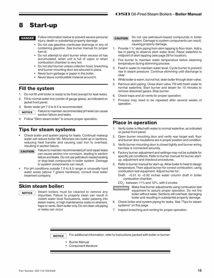
8 Start-up
Follow information below to prevent severe personalinjury, death or substantial property damage:
• Do not use gasoline crankcase drainings or any oilcontaining gasoline. See burner manual for properfuel oil.
• Do not attempt to start burner when excess oil hasaccumulated, when unit is full of vapor or whencombustion chamber is very hot.
• Do not start burner unless collector hood, breechingand burner mounting door are secured in place.
• Never burn garbage or paper in the boiler.• Never leave combustible material around it.
Do not use petroleum-based compounds in boilersystem. Damage to system components can result,causing property damage.
1. Provide 1 ½" skim piping from skim tapping to floor drain. Add atee in piping to observe skim water level. Raise waterline tomidpoint of skim tapping (see page 26 for location).
2. Fire burner to maintain water temperature below steamingtemperature during skimming process.
3. Feed in water to maintain water level. Cycle burner to preventrise in steam pressure. Continue skimming until discharge isclear.
4. While boiler is warm, but not hot, drain boiler through drain valve.5. Remove skim piping. Close drain valve. Fill with fresh water to
normal waterline. Start burner and steam for 15 minutes toremove dissolved gases. Stop burner.
6. Check traps and air vents for proper operation.7. Process may need to be repeated after several weeks of
operation.
Fill the system1. Do not fill until boiler is ready to be fired (except for leak tests).2. Fill to normal water line (center of gauge glass), as indicated on
jacket front panel.3. Boiler water pH 7.0 to 8.5 is recommended.
Failure to maintain recommended pH level can causesection failure and leaks.
4. Follow “Skim steam boiler” to ensure proper operation.
Tips for steam systems• Check boiler and system piping for leaks. Continual makeup
water will reduce boiler life. Minerals can build up in sections,reducing heat transfer and causing cast iron to overheat,resulting in section failure.
Failure to maintain recommended pH and repair leakscan cause section iron corrosion, leading to sectionfailure and leaks. Do not use petroleum-based sealingor stop-leak compounds in boiler system. Damageto system components can result.
• For pH conditions outside 7.0 to 8.5 range or unusually hardwater areas (above 7 grains hardness), consult local watertreatment company.
Skim steam boiler:Steam boilers must be cleaned to remove anyimpurities. Failure to properly clean can result inviolent water level fluctuations, water passing intosteam mains, or high maintenance costs on strainers,traps or vents. Skim boiler only. Do not clean old pipingor leaks can occur.
Place in operation1. Verify boiler is filled with water to normal waterline, as indicated
on jacket front panel.2. Open burner mounting door and verify rear target wall, floor
and burner door insulations are in proper position and condition.3. Verify burner mounting door is closed tightly and burner wiring
harness is connected securely.4. Factory burner adjustment and settings may not be suitable for
specific job conditions. Refer to burner manual for burner start-up, adjustment and checkout procedures.
5. Refer to burner manual for start-up. Allow boiler to heat to designtemperature. Then adjust burner for correct combustion, usingcombustion test equipment. Adjust burner for:Draft: –0.01 to –0.02 inches water column draft in boiler
combustion chamber.CO2: between 11% and 12%, with 0 smoke.
Make final burner adjustments using combustion testequipment to assure proper operation. Do not fireboiler without water. Sections will overheat, damagingboiler and resulting in substantial property damage.
6. Check boiler and system piping for leaks. See “Tips for steamsystems” on this page.
7. Inspect breeching and venting for proper operation.
For additional information, refer to instructions packed with boiler or burner:
• Burner Manual• Component literature

OSB Oil-Fired Steam Boilers – Boiler Manual
16 Part Number 550-110-752/0402
9 Checkout procedure
❑ 1. Boiler properly filled with water?
❑ 2. Boiler piping check for leaks (including tankless heater, ifused)?
❑ 3. System vents and/or traps operating properly?
❑ 4. Boiler properly skimmed?
❑ 5. Air purged from oil piping? Piping checked for leaks?Burner door closed, sealed and nut tight? Burner harnesssecurely plugged in?
Obtain gas-tight seal at burner door to preventpossible flue gas leakage and carbon monoxideemissions, leading to severe personal injury or death.
❑ 6. Proper draft and burner flame? Final adjustment madewith combustion test equipment?
❑ 7. Test pressure limit control: While burner is operating, moveindicator on limit control below actual boiler steampressure. Burner should go off. Raise setting on limit controlabove boiler steam pressure and burner should reignite.
❑ 8. Test low water cutoff(s): Follow control manufacturer’sinstructions for testing procedures. Make sure burner goesoff when control responds to low water condition. Burnershould re-ignite when proper water level is restored.
❑ 9. Test additional field-installed controls: If boiler has additionaloperating control or other controls, test for operation asoutlined by control manufacturer. Burner should beoperating and should go off when controls are tested. Whencontrols are restored, burner should reignite.
❑ 10. Limit control set to system pressure requirements?
❑ 11. Thermostat heat anticipator setting (if available) setproperly? Refer to “Connect wiring,” page 11.
❑ 12. Boiler cycled with thermostat? Raise to highest settingand verify boiler goes through normal start-up cycle. Lowerto lowest setting and verify boiler goes off.
❑ 13. Observed several operating cycles for proper operation?
❑ 14. Set room thermostat(s) to desired room temperature?
❑ 15. Completed “Installation and service certificate” below?
❑ 16. Reviewed User’s Information Manual with owner ormaintenance person and instructed person to keep forfuture reference?
❑ 17. Returned all instructions provided with boiler to its envelopeand placed with boiler for future reference?
Check off steps as completed

17Part Number 550-110-752/0402
OSB Oil-Fired Steam Boilers – Boiler Manual
Boiler model _______________________________________________________________ Series ____________
CP number _______________________________________ Date installed _________________________________
Measured Btuh input ____________
Installer _______________________ ______________________________ ____________________________ (company) (address) (phone)
_____________________________________
(installer’s signature)
Installation instructions have been followed.
Checkout sequence has been performed.
Above information is certified to be correct.
Information received and left with owner/maintenance person.
9 Checkout procedure continued

OSB Oil-Fired Steam Boilers – Boiler Manual
18 Part Number 550-110-752/0402
10 Service and maintenance
The boiler should be inspected and started annually, at the beginning of the heating season, only by a qualified servicetechnician. In addition, the maintenance and care of the boiler designated in the table below, and explained on the followingpages must be performed to assure maximum boiler efficiency and reliability. Failure to service and maintain the boiler andsystem could result in equipment failure.
Follow the “Service and maintenance” procedures given throughout this manual and in component literature shipped withthe boiler. Failure to perform the service and maintenance could result in damage to the boiler or system. Failure to follow thedirections in this manual and component literature could result in severe personal injury, death or substantial propertydamage.
Annual service and start-up
tsiLkcehCllaCecivreSlaunnA)wolebdetsilredroniwollof(
DATE
DATE
DATE
DATE
DATE
DATE
DATE
DATE
DATE
DATE stnemmoC
1 .91egapeeS.syaweulfreliobnaelC
2 elbitsubmocmorfeerfsiaerareliobtahtkcehCdnasropavelbammalfrehtodnaenilosag,slairetam
.sdiuqil
3 otnoitcurtsboynaevomerdnarofkcehCreliobotwolfrianoitalitnevdnanoitsubmoc
4 firiaperdnaskaelrofgnipipdnareliobkcehC.dnuof
5 evlavfeiler,ffotucretawwolnoecivresmrofreP.12dna02segapeeS.ssalgeguagdna
6 roftnevroyenmihcdnagnihceerbkcehCsaecalperroriapeR.cte,egamad,snoitcurtsbo
.yrassecen
7 .levelretawtcerrocotdellifsirelioberusekaM.02egapeeS
8 :dnalaunamrenrubeeS.renrubtsujdadnatcepsnI.elzzonegnahc-
.sgnittesedortcelenoitingikcehc-.leehwdnagnisuohrewolbnaelc-
.yleerfsnrutleehwrewolberusekam-.deriuqerfirotomrenrublio-
.telnirianaelc-.reniartsdnaretlifleufegnahcronaelc-
9 htiwsgnittesnoitsubmocyfirevdnatinutratS.tnempiuqetsetnoitsubmoc
.12egapeeS
01 .reliobnoslortnocllafonoitarepoyfireV

19Part Number 550-110-752/0402
OSB Oil-Fired Steam Boilers – Boiler Manual
Cleaning boiler fluewaysThe boiler contains ceramic fiber and fiberglassmaterials. Use care when handling these materialsper instructions on page 28 of this manual. Failure tocomply could result in severe personal injury.
Figure 15 Cleaning boiler flueways — Thoroughly cleanflueways between all pins at all angles. Starton top of boiler, finish from the bottom.
Make sure all electrical connections to boiler areturned off and wait until boiler is warm, not hot, beforecleaning. Failure to do so will result in severe personalinjury, death or substantial property damage.
1. Remove jacket top panel.2. Remove flue collector hood, saving hardware for reassembly.3. Shut off oil valves. Arrange drip pans under the areas of oil
piping that will be disconnected. Disconnect oil line at burner sothat you can swing open the door completely.
4. Line combustion chamber floor with newspaper to catch anysoot that will be loosened in the cleaning process.
5. Starting at the top of the boiler, use a wire flue brush to thoroughlyclean between all pins at all angles. Be careful not to damageside walls of rear refractory.
6. Move to the bottom of the flueways and clean up between thesections to reach pins left uncleaned in step #5.
7. Once the flueways are cleaned, carefully remove the paperfrom the floor of the combustion chamber. Fold the paper tocapture the refuse, seal in a plastic bag, and dispose.
8. Verify sealing rope around flue area is intact. Visually checkcondition and position of insulation in combustion chamber floor,and the refractories at the rear of boiler and in the burnermounting door. Replace any parts as necessary.
9. Close burner mounting door and tighten nut securely. Placeflue collector hood on top of boiler. Secure with hardware fromstep #2. Maintain a gas-tight seal to avoid possible flue gasleakage and carbon monoxide emissions, which can lead tosevere personal injury or death.
10. Check breeching for sooting and clean if necessary. Installjacket top panel and breeching.
11. Reconnect oil line and all electrical connections.
Wear a NIOSH -certified dust respirator (N95) whilecleaning the boiler, per WARNING on page 28. Failureto comply could result in severe personal injury.
10 Service and maintenance continued
Reported problemsInspect any problems reported by owner and correct beforeproceeding.
Boiler area1. Verify that boiler area is free of any combustible materials,
gasoline and other flammable vapors and liquids.2. Verify that boiler area is free of any of the contaminants listed in
Table 2 on page 5 of this manual. If any of these are present inthe boiler intake air vicinity, they must be removed. If they cannotbe removed, install combustion air piping to the boiler inaccordance with national, provincial or local codes.
❏❏❏❏❏ Inspect . . . . . . . . . .
Piping1. Check the boiler interior piping and all system piping for signs
of leaks.2. Repair any leaks before proceeding.
Do not use petroleum-based cleaning or sealingcompounds in boiler system. Severe damage to boilerwill occur, resulting in substantial property damage.Eliminate all system or boiler leaks. Continual freshmakeup water will reduce boiler life. Minerals canbuild up in sections, reducing heat transfer,overheating cast iron, and causing section failure.Leaking water may also cause severe propertydamage.

OSB Oil-Fired Steam Boilers – Boiler Manual
20 Part Number 550-110-752/0402
10 Service and maintenance continued
Gauge glassNormal waterline is halfway up gauge glass. Clean when needed.1. Close lower gauge cock.2. Open pet cock.3. Open lower gauge cock and allow a small amount of water to
flush out through open pet cock.4. Close pet cock.5. Open lower gauge cock.
Boiler pressure must be low to eliminate potential ofsevere burns.If gauge glass breaks, close both gauge cocks.Replace gauge glass. Do not replace with thin glasstubing. Failure to comply could cause severe personalinjury, death or substantial property damage.
❏❏❏❏❏ Service. . . . . . . . . .
❏❏❏❏❏ Check/test. . . . . . . . . .
Boiler waterlineNormal waterline is halfway up gauge glass.
Limit controls1. Inspect and test the boiler limit control. Verify operation by turning
control set point below boiler pressure. Boiler should cycle off.Return dial to original setting.
❏❏❏❏❏ Check/test. . . . . . . . . .Low water cutoffs
Probe-type low water cutoff (see below)Clean and test probe-type low water cutoff for proper operation.Remove, inspect and clean the low water cutoff at least annuallybefore testing. Refer to low water cutoff manufacturer’s instructionsin envelope assembly provided with boiler.1. Turn off power to boiler and wait 5 minutes.2. Drain water to bottom of gauge glass.3. Turn on power.4. Set thermostat to call for heat. Red neon lamp on lower water
cutoff should light.5. Wait 5 minutes. Boiler should not fire.6. Refill boiler to correct waterline. Red lamp should go off.7. Wait 5 minutes. Boiler should fire.8. Return thermostat to normal setting.
Float-type low water cutoff (when provided by others— see below)Clean and test float-type low water cutoff (when provided by others)to clear float chamber of sediment.1. Open blowdown valve at bottom control.2. Drain water into a bucket.
Scald potential. Boiler pressure must be low to avoidthe potential of severe burns from steam.
3. Check float-type low water cutoff for proper operation:a. Turn operating control to call for heat.b. Before water gets hot, drain to bottom of gauge glass. Boiler
should shut off after water level lowers a few inches.c. Refill boiler to correct waterline. Boiler should come back
on.
21Part Number 550-110-752/0402
OSB Oil-Fired Steam Boilers – Boiler Manual
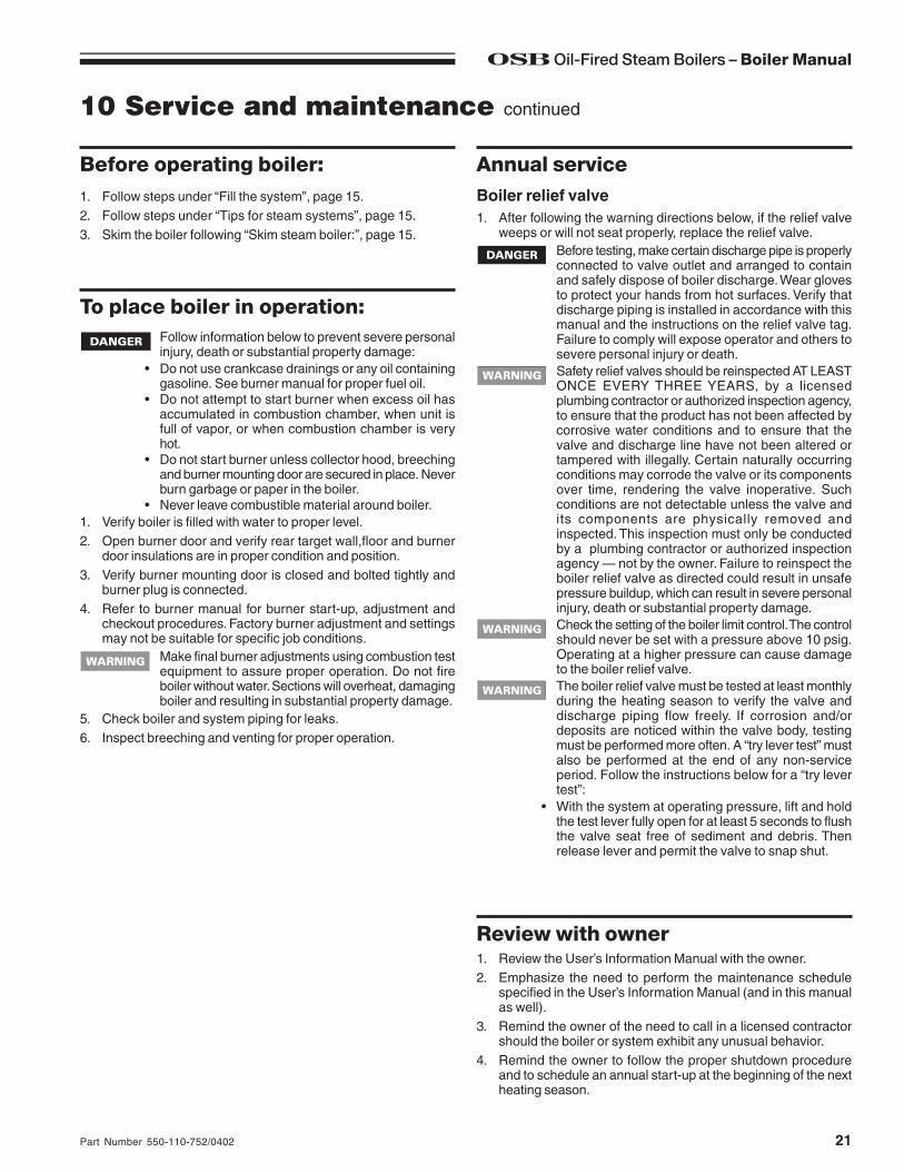
Before operating boiler: Annual service1. Follow steps under “Fill the system”, page 15.2. Follow steps under “Tips for steam systems”, page 15.3. Skim the boiler following “Skim steam boiler:”, page 15.
10 Service and maintenance continued
To place boiler in operation:Follow information below to prevent severe personalinjury, death or substantial property damage:
• Do not use crankcase drainings or any oil containinggasoline. See burner manual for proper fuel oil.
• Do not attempt to start burner when excess oil hasaccumulated in combustion chamber, when unit isfull of vapor, or when combustion chamber is veryhot.
• Do not start burner unless collector hood, breechingand burner mounting door are secured in place. Neverburn garbage or paper in the boiler.
• Never leave combustible material around boiler.1. Verify boiler is filled with water to proper level.2. Open burner door and verify rear target wall,floor and burner
door insulations are in proper condition and position.3. Verify burner mounting door is closed and bolted tightly and
burner plug is connected.4. Refer to burner manual for burner start-up, adjustment and
checkout procedures. Factory burner adjustment and settingsmay not be suitable for specific job conditions.
Make final burner adjustments using combustion testequipment to assure proper operation. Do not fireboiler without water. Sections will overheat, damagingboiler and resulting in substantial property damage.
5. Check boiler and system piping for leaks.6. Inspect breeching and venting for proper operation.
Boiler relief valve1. After following the warning directions below, if the relief valve
weeps or will not seat properly, replace the relief valve.Before testing, make certain discharge pipe is properlyconnected to valve outlet and arranged to containand safely dispose of boiler discharge. Wear glovesto protect your hands from hot surfaces. Verify thatdischarge piping is installed in accordance with thismanual and the instructions on the relief valve tag.Failure to comply will expose operator and others tosevere personal injury or death.Safety relief valves should be reinspected AT LEASTONCE EVERY THREE YEARS, by a licensedplumbing contractor or authorized inspection agency,to ensure that the product has not been affected bycorrosive water conditions and to ensure that thevalve and discharge line have not been altered ortampered with illegally. Certain naturally occurringconditions may corrode the valve or its componentsover time, rendering the valve inoperative. Suchconditions are not detectable unless the valve andits components are physically removed andinspected. This inspection must only be conductedby a plumbing contractor or authorized inspectionagency — not by the owner. Failure to reinspect theboiler relief valve as directed could result in unsafepressure buildup, which can result in severe personalinjury, death or substantial property damage.Check the setting of the boiler limit control. The controlshould never be set with a pressure above 10 psig.Operating at a higher pressure can cause damageto the boiler relief valve.The boiler relief valve must be tested at least monthlyduring the heating season to verify the valve anddischarge piping flow freely. If corrosion and/ordeposits are noticed within the valve body, testingmust be performed more often. A “try lever test” mustalso be performed at the end of any non-serviceperiod. Follow the instructions below for a “try levertest”:
• With the system at operating pressure, lift and holdthe test lever fully open for at least 5 seconds to flushthe valve seat free of sediment and debris. Thenrelease lever and permit the valve to snap shut.
Review with owner1. Review the User’s Information Manual with the owner.2. Emphasize the need to perform the maintenance schedule
specified in the User’s Information Manual (and in this manualas well).
3. Remind the owner of the need to call in a licensed contractorshould the boiler or system exhibit any unusual behavior.
4. Remind the owner to follow the proper shutdown procedureand to schedule an annual start-up at the beginning of the nextheating season.

OSB Oil-Fired Steam Boilers – Boiler Manual
22 Part Number 550-110-752/0402
11 Replacement parts
Figure 16 Boiler section assembly, refractories, collector hood and burner door assembly

23Part Number 550-110-752/0402
OSB Oil-Fired Steam Boilers – Boiler Manual
Table 8 Parts list for Figure 16
11 Replacement parts continued

OSB Oil-Fired Steam Boilers – Boiler Manual
24 Part Number 550-110-752/0402
11 Replacement parts continued
Figure 17 Jacket parts and replacement instructions
The boiler contains ceramic fiber and fiberglassmaterials. Use care when handling these materialsper instructions on page 28 of this manual. Failure tocomply could result in severe personal injury.
Before installing jacket:Before installing jacket:1. Remove the following knockouts:
• Steam return knockout (lower left back panel).• Relief valve knockout (upper right back panel).• Rectangular tankless heater and tankless control knockouts
(left side panel), if tankless heater is to be installed.• Remaining knockout (right back panel) if indirect-fired water
heater is to be installed.2. Make sure all unused tappings are plugged.3. These parts may be on boiler:
• Supply piping• Drain valve• Tankless heater
4. These parts must be off boiler:• Breeching connection• Steam or water trim parts and piping• Tankless heater control and piping• Return piping• Steam or water relief valve and piping
5. Remove burner mounting door by removing locking nut andlifting door off hinge. Do not remove hinge.
To install jacket:1. Install jacket front panel to front section, making sure burner
door hinge lugs extend through holes in lower jacket leg. Securewith two 3/8" x 1/2" black machine screws.
2. Right and left side pieces are shipped as straight pieces. Beforeinstalling, bend about 90° at perforation as shown, to form sidesand back panels.a. Secure side panels to front panel with four sheet metal
screws.b. To secure back panels, using two 1/4" x 1/2" self-tapping
screws:1) Start upper screw in boiler section. Do not tighten.2) Slip keyhole opening in back panels behind screw.3) Install lower screw and tighten both screws.
c. Install top panel and secure with two sheet metal screws.3. Reinstall burner mounting door and secure locking nut on stud,
making sure door is secured gas-tight.Gas-tight seal must be obtained at door to preventpossible flue gas leakage and carbon monoxideemissions, leading to severe personal injury or death.

25Part Number 550-110-752/0402
OSB Oil-Fired Steam Boilers – Boiler Manual
Figure 18 Trim and controls
11 Replacement parts continued

OSB Oil-Fired Steam Boilers – Boiler Manual
26 Part Number 550-110-752/0402
Figure 19 Dimensional drawing — ALL DIMENSIONS IN INCHES
12 Dimensions

27Part Number 550-110-752/0402
OSB Oil-Fired Steam Boilers – Boiler Manual
13 Ratings
DOE
Notes1. See information at right for model number suffixes.2. MBH refers to thousands of Btu per hour.3. Base on 140,000 Btu per gallon.4. Based on standard test procedures prescribed by the United States Department of
Energy.5. Net I=B=R ratings are based on net installed radiation of sufficient quantity for the
requirements of the building and nothing need be added for normal piping and pickup.Ratings are based on a piping and pickup allowance of 1.333. An additionalallowance should be made for unusual piping and pickup loads.
6. See page 6 for minimum breeching diameter.7. Listed draft losses are for factory-shipped settings.
OSB boilers are designed for installation on combustible flooring.OSB boilers are ASME rated for 50 psig working pressure.
Boilermodelnumber
I=B=R burner
capacityGPH
DOEheating capacity
MBH
Net I=B=Rratings MBH
DOEseasonal efficiency% AFUE
Round flue
outlet size inches
Minimum I=B=RChimney
Boiler water
content(gallons
@ normal waterline)
Draft loss through boiler
inches W.C.Steamsq. feet
Steam MBH
Rectangleinches
Round inches
Heightfeet
Note 2 Notes 2 & 3 Notes 1 & 4 Note 5 Note 6 Note 7
OSB-3-100 1.00 116 363 87 82.1 7 8 x 8 6 15 10.7 .000
OSB-4-110 1.10 129 404 97 82.0 7 8 x 8 6 15 12.5 .010
OSB-4-125 1.25 145 454 109 81.7 7 8 x 8 6 15 12.5 .010
OSB-5-135 1.35 158 492 119 81.5 7 8 x 8 7 15 14.2 .010
OSB-5-150 1.50 175 546 131 81.4 7 8 x 8 7 15 14.2 .010
OSB-6-175 1.75 204 638 153 81.1 7 8 x 8 7 15 16.0 .000
OSB-6-200 2.00 232 725 174 81.4 7 8 x 8 7 15 16.0 .015
OSB Oil-Fired Steam Boilers – Boiler Manual
28 Part Number 550-110-752/0402
W-T8201 W. Calumet Rd.Milwaukee, WI 53223
REMOVAL OF COMBUSTION CHAMBER LINING OR BASE PANELS
The combustion chamber lining or base insulation panels in this product contain ceramic fiber materials. Ceramicfibers can be converted to cristobalite in very high temperature applications. The International Agency for Researchon Cancer (IARC) has concluded, "Crystalline silica inhaled in the form of quartz or cristobalite from occupationalsources is carcinogenic to humans (Group 1).":
■ Avoid breathing dust and contact with skin and eyes.
• Use NIOSH certified dust respirator (N95). This type of respirator is based on the OSHA requirements forcristobalite at the time this document was written. Other types of respirators may be needed depending onthe job site conditions. Current NIOSH recommendations can be found on the NIOSH web site at http://www.cdc.gov/niosh/homepage.html. NIOSH approved respirators, manufacturers, and phone numbers arealso listed on this web site.
• Wear long-sleeved, loose fitting clothing, gloves, and eye protection.
■ Apply enough water to the combustion chamber lining or base insulation to prevent airborne dust.
■ Remove combustion chamber lining or base insulation from the boiler and place it in a plastic bag for disposal.
■ Wash potentially contaminated clothes separately from other clothing. Rinse clothes washer thoroughly.
NIOSH stated First Aid.■ Eye: Irrigate immediately
■ Breathing: Fresh air.
REMOVAL OF FIBERGLASS WOOL — OR —
INSTALLATION OF FIBERGLASS WOOL, COMBUSTION CHAMBER LINING OR BASEPANELS:
This product contains fiberglass jacket insulation and ceramic fiber materials in combustion chamber lining or basepanels in gas fired products. Airborne fibers from these materials have been listed by the State of California as apossible cause of cancer through inhalation.
■ Avoid breathing dust and contact with skin and eyes.
• Use NIOSH certified dust respirator (N95). This type of respirator is based on the OSHA requirements forfiberglass wool at the time this document was written. Other types of respirators may be needed dependingon the job site conditions. Current NIOSH recommendations can be found on the NIOSH web site at http://www.cdc.gov/niosh/homepage.html. NIOSH approved respirators, manufacturers, and phone numbers arealso listed on this web site.
• Wear long-sleeved, loose fitting clothing, gloves, and eye protection.
■ Operations such as sawing, blowing, tear out, and spraying may generate airborne fiber concentration requiringadditional protection.
■ Wash potentially contaminated clothes separately from other clothing. Rinse clothes washer thoroughly.
NIOSH stated First Aid.■ Eye: Irrigate immediately
■ Breathing: Fresh air.
Handling ceramic fiber and fiberglass materials


![1&( & GAS-FIRED Models STEAM BOILERS REV D PEG IOM.pdf · 1&( & GAS-FIRED STEAM BOILERS INSTALLATION, OPERATION & MAINTENANCE MANUAL P/N 240009937, Rev. D [04/30/2017] MODEL PEGEID](https://img.pdfslide.us/doc/110x75/5ad8e1c37f8b9ab8378de155/1-gas-fired-models-steam-rev-d-peg-iompdf1-gas-fired-steam-boilers-installation.jpg)


![GAS-FIRED STEAM BOILERS · GAS-FIRED STEAM BOILERS INSTALLATION, OPERATION & MAINTENANCE MANUAL P/N# 240009572, Rev. B [07/2012] MODEL PEGDID Electronic Intermittent Ignition An ISO](https://img.pdfslide.us/doc/110x75/5d5f2dac88c993e3528b930c/gas-fired-steam-boilers-gas-fired-steam-boilers-installation-operation-maintenance.jpg)