Embed Size (px)
Citation preview

Methodologies for Power Protection Relay Testing: From Conventional to Real-Time Hardware-in-the-Loop (HIL) Simulation Approaches
M. S. Almas and L. Vanfretti
KTH Royal Institute of Technology, Stockholm, Sweden
Abstract-- Performance testing of the protection relays ensures
that a particular protection scheme will operate reliably and fast
enough to disconnect a faulty zone from the rest of the network,
thus mitigating the effect of fault on the power system. It is
therefore important to validate the settings of power protection
equipment and to confirm its performance when subject to
different fault conditions. Traditionally, commissioning engineers
make use of standalone protection relay test sets for analyzing the
performance of relays when subjected to different voltage and
current injections. With the advent of digital simulators the model
of the power system can be executed in real-time and protection
relays can be interfaced as hardware-in-the-loop to evaluate their
performance when subjected to different faults in the simulated
power system. This gives an added value of analyzing the overall
behavior of the power system coupled with the relay performance
under faulty conditions. In addition, the utilization of GOOSE
messages for status, control and protection purposes puts an extra
requirement to completely test the IEC 61850 capabilities of the
protection relays.
This article illustrates two different techniques namely
standalone testing and real-time hardware-in-the-loop testing
used for protection relays performance verification. Both
techniques are evaluated for hardwired and IEC 61850-8-1
(GOOSE) signals. The instantaneous overcurrent protection
feature of Schweitzer Engineering Laboratories Relay SEL-421 is
used for complete standalone and RT-HIL testing. For RT-HIL
testing, the test case is modeled in MATLAB/Simulink and
executed in real-time using Opal-RT's eMEGAsim real-time
simulator. The event reports generated by standalone and RT-
HIL testing for both hardwired and GOOSE signals is used to
verify the tripping times achieved. Finally the performance of
hardwired and GOOSE tripping times are compared and the
overall standalone and RT-HIL techniques are evaluated.
Keywords: Real-Time Simulation, Hardware-in-the-Loop,
Overcurrent Protection, Power Protection Relay Testing, Opal-
RT, GOOSE, Station Bus
M. S. Almas is a PhD. student at the division of Electric Power Systems,
Royal Institute of Technology, Stockholm, Sweden ([email protected]). He is
supported by STRONg2rid project, funded by Nordic Energy Research.
L. Vanfretti is a Docent and Assitant Professor at the division of Electric
Power Systems, Royal Institute of Technology, Stockholm, Sweden
([email protected]). He is supported by the STandUP for Energy collaboration
initiative, Nordic Energy Research hrough the STRONg2rid project and the
European Commission through the iTesla FP7 project.
Paper submitted to the International Conference on Power Systems
Transients (IPST2013) in Vancouver, Canada June 18-20, 2013.
I. INTRODUCTION
OWER protection relays play the most vital role for
safeguard the power system from detrimental effects of
faults. Microprocessor based relays or IEDs are equipped with
current and voltage input modules which receive the voltage
and current measurements from VT and CT respectively. The
algorithms incorporated in their microprocessors utilize these
measured voltage and current values to detect faults in the
power system. These IED's generate a trip signal once the
algorithm detects the faulty condition. This trip signal is used
to open the circuit breaker, send information to the control
center, communicate with other devices/controllers in the
substation etc. [1].
Mal-functioning of relays can lead to false tripping of
circuit breakers which can cause cascading failures. Therefore
it is important to verify the settings of protection relays before
they are commissioned in the real power system to avoid any
unfortunate incident. Traditionally field engineers or
commissioning engineers use stand-alone relay test sets to
verify protection relays settings. This is also called static
characteristic testing set which are provided by different
manufacturers (suppliers) [2]. These test sets are actually three
phase variable voltage and current sources which are used to
provide secondary injections to the protection relays. The
features verified are the accurate fault detection by the relay,
tripping time, output contact status change etc. These test sets
do provide the advantage of being compact and portable;
however, most are limited to 6 current channels and 6 voltage
channels. With this limitation, it is cumbersome to use several
of these test sets to verify complex protection schemes like bus
bar protection. In addition the synchronization of the two test
sets with GPS will be an additional issue.
Real-time simulators (RTS) are currently being used to
simulate large power systems and to analyze their behavior in
both steady state and faulted states. These RTSs are equipped
with Analog and Digital I/Os and can be interfaced with the
real devices. Such kind of approach is called RT HIL
simulation [3]. This approach allows performing complete
functional testing of the protection relays. In this case an
accurate model of the power system where the relay is to be
placed is modeled and simulated in RT using the RTS with the
actual hardware (protection relay) as HIL. The key benefit in
RT HIL protection relay testing is that the impact of the fault
on overall power system can be analyzed and the overall
protection schemes including the backup protections, system
P

Thevenin Equivalent
(Strong Grid)
Bus 1
Transmission Line Length = 2Km
30 MW Load
SEL_421(Set for OverCurrent Protection)
CTCircuit Breaker
Digital output of relay connected directly to
breaker for Trip
Fault11kV, 50 HzShort Circuit Capacity = 500MVA
Bus 2
Fig. 1. Single Line Diagram of the Test Case
integrity protection schemes (SIPS), Remedial Action
Schemes (RAS) can be verified.
In this paper, two techniques used for relay testing:
standalone testing and RT HIL are compared for both
hardwired and IEC 61850-8-1 (GOOSE) testing. Firstly a test
system is designed in SPS and its fault analysis is carried out.
Based on the fault analysis, the settings of the protection relay
from Schweitzer Engineering Laboratories (SEL) relay SEL-
421 [4] are configured for instantaneous overcurrent
protection. In standalone testing, the secondary injections for
three phase currents are provided by the relay test set from
Megger and the tripping times are noted for both hardwired
and GOOSE testing. Then the SPS model is executed in RT
using Opal-RT's eMEGAsim real-time simulator. The same
SEL-421 relay with same parameters is used for RT HIL
testing for both hardwired and GOOSE signals. The results
obtained are verified by retrieving the event report of SEL-421
for the entire test scenarios.
The remainder of this article is arranged as follows.
Section II presents the details of the test case modeled in SPS.
Section III focuses on the stand-alone hardwired testing of
SEL-421 for over-current protection function. Section IV
provides the stand-alone testing with GOOSE (IEC 61850-8-
1). Real-time hardwired testing using Opal-RT is discussed in
Section V, while Real-Time GOOSE testing is explained in
Section VI. Finally in Section VII, conclusions are drawn and
future work is outlined.
II. TEST CASE IN SIMPOWERSYSTEMS
The test case is modeled using the SimPowerSystems
(MATLAB / Simulink) Toolbox. SPS is a dedicated tool for
modeling and simulating power systems [5]. Another
motivation behind using SPS toolbox is because the models
built in SPS are compatible with Opal-RT eMEGAsim real-
time simulator [6] and can be executed in RT. Figure 1 shows
the single line diagram of the test case modeled in SPS. The
major components of the power system model are;
Three phase voltage source, 50Hz, 11kV phase
voltage and short circuit capacity of 500MVA
Transmission Line (π -section), 2km
Three phase fault block to introduce three phase fault
Circuit breaker to disconnect load with trip signals
from overcurrent relay (SEL-421)
Three phase series RLC load of 30MW
Simulation time step = 50 µ second
In order to set the parameters of the protection relay (SEL-
421) like CT ratio and pickup value, fault analysis of the test
case was performed. The results are shown in Figure 2. Based
on the results from the fault analysis, the settings of the SEL-
421 were modified using SEL AcSELerator Quickset [7]. The
key parameters settings for the SEL-421 are shown in Table 1.
TABLE I
TEST SYSTEM ANALYSIS AND RELAY SETTINGS
Measurements
Full Load Current 1500 A
Maximum Fault
Current (Three
Phase Fault)
7120 A
Relay Setting
Current
Transformer Ratio
1500:1
Pickup Value 2 A
Characteristic Instantaneous
Event Report 2.5 sec
Digital Output of
Relay
Trip=Normal Close
0 0.1 0.2 0.3 0.4-4000
-2000
0
2000
4000 X: 0.339
Y: 2121
Instantaneous Current at Load Bus
Simulation Time (sec)
Cu
rren
t
(Am
pere
s)
0 0.1 0.2 0.3 0.40
500
1000
1500
2000 X: 0.3715
Y: 1500
Cu
rrn
et
(Am
pere
s)
Simulation Time (sec)
RMS Current at Load Bus
0 0.1 0.2 0.3 0.4-2
-1
0
1
2x 10
4
X: 0.3031
Y: 1.007e+004
SimulationTime (sec)
Fa
ult
Cu
rren
t(A
mp
ere
s)
Fault Current at Load Bus
0 0.1 0.2 0.3 0.40
5000
10000
15000
X: 0.3974
Y: 7120
Simulation Time (sec)
RM
S F
au
lt C
urr
en
t(A
mp
ere
s)
RMS Fault Current at Load Bus
Phase A
Phase B
Phase C
Fig. 2. Fault Analysis of Test Case
III. STANDALONE TESTING HARDWIRED
For standalone relay testing the Freja 300 relay test system
was used [8]. The voltage and current sources are connected to
the CT and VT input modules of the relay. By injecting
different voltage, current magnitudes, phases and frequency,
harmonics, different protection functions of the relays can be
verified. For the standalone testing we have used Freja 300
along with its software interface Freja Win [9] to provide
secondary injections to the SEL-421 relay to test its
instantaneous overcurrent protection function.
The instantaneous overcurrent protection function sends a
trip command to the breaker as soon as the fault is detected
(input current greater than the pre-set value). They don't have
any intentional time delay. They are usually implemented close
to the source where the fault current level is very high and a
small delay in operation of relay can cause heavy damage to

the equipment. So an instantaneous relay is used there to detect
and respond to a fault in few cycles. The workflow diagram of
testing a relay with Freja-300 is shown in Figure 3 and the
screenshot of the graphical interface for Freja-300 test set
i.e._Freja Win is shown in Figure 4.
For the test case, three phase current injection of 1 A
(RMS) was provided for the first 2 seconds and at t =2 sec, the
current injection was increased to 4.74 A (RMS). These are
the same steady state and maximum fault current values as
shown in Figure 2 and Table 1 but on the secondary side of the
CT (CT ratio is 1500:1).
At t = 2 sec, when the current injection increases, the relay
picks it up as an overcurrent fault and generates a trip signal.
The digital output of SEL-421 configured for overcurrent trip
changes its status from normal open to normal close which is
detected by the binary input of Freja-300 and the test scenario
is terminated.
CT Input
VT InputDigital I/O
Three phase voltage injection to the relay under test
Three phase current injection to the relay under test
Digital I/O of the relay under test. The Digital Output is configured to change its contact from normal open to normal
close when a protection function
operates
Workstation with software FREJA Win which is a graphical interface
for the FREJA 300 Relay Testing System
Relay Test SetFreja 300
Relay under TestDistance Relay (SEL-421)
1
2
Fig. 3. Hardwired Standalone Relay Testing Using Freja-300 Relay Test Set
Fig. 4. Software Freja Win Interface for Standalone Relay Testing
The injections given by the test set are shown in Figure 5. Here
State 1 is the pre-fault state and State 2 is the faulty state with
increased current injections. The results show that at t = 2 sec,
the current injections are increased and the trip signal from the
digital output of the SEL-421 is received at 2.0083 sec i.e. the
overall time from fault pickup to trip generation and changing
output contact status of the relay is 8.3 msec.
In order to verify these results, the oscillography/event
report of SEL-421 was acquired by using SEL Analytic
Assistant software [10]. Figure 6 shows that the fault is applied
at t = 2 sec i.e. at 100th
cycle and the relay has detected the
overcurrent situation in almost quarter of cycle i.e. t = 2.005
sec. So 5 msec is taken by SEL-421 to decide if the
instantaneous overcurrent has occurred. The rest 3.3 msec is
utilized by the relay to change its output contact and utilized
by the test set to read its binary input status and end the test
scenario.
Fig. 5. Test Result for Standalone Testing (Hardwired)
Fig. 6. Event Report from SEL-421 for Hardwired Standalone Testing
IV. STANDALONE TESTING GOOSE
The substation automation architecture standard IEC 61850
is currently being implemented a large number of currently
available IEDs are IEC 61850 compliant [11]. One major
benefit of the IEC 61850 standard is the reduction in
construction cost due to eliminating the need of copper wiring.
In addition the standard allows multi-vendor interoperability
and high speed peer to peer communications. Substations have
already implemented the concept of Station Bus [12] and
GOOSE [13] is being utilized for breaker failure, back up

protections, fault recording, disconnector and circuit breakers
interlocking. This calls a need for accurately testing the
GOOSE features of the IEDs. SEL-421 is also IEC 61850-8-1
complaint.
The software SEL AcSELerator Architect [14] is used to
create GOOSE transmits messages for the SEL-421. The
GOOSE message was configured for overcurrent protection
trip. This overcurrent protection trip is a binary value which
gives '0' in normal state and '1' in case of overcurrent trip. The
overall test setup is shown in Figure 7. The secondary
injections are provided by the Freja Relay Test Set as
explained in Section III. However the trip signal is not
received by the digital output of the relay. Instead test set
GOOSER [15] along with its software interface PC-GOOSER
[16] is used to capture the GOOSE message from the network
and translate this GOOSE message to its binary outputs. This
binary output of the GOOSER is connected to the binary input
of the Freja-300. So as soon as the overcurrent situation is
detected by SEL-421, it transmits a changed status of GOOSE
message which is captured by GOOSER and it changes status
of its binary output which is sensed by Freja-300 to terminate
the test scenario i.e. stop the secondary injections of three
phase current.
Current/Voltage Injection by Relay Test Set
Gooser configured to change its binary output contact upon receiving of GOOSE message
Station Bus(IEC-61850-8-1)
1
2
3
Output contacts of GOOSER are connected to inputs of Relay Test Set. As the GOOSER changes its output contacts, the relay test set determines
a change in its binary inputs and ends the test
Relay under TestDistance Relay (SEL-421)
IEC 61850-8-1 Test SetGOOSER
Relay Test SetFreja 300
Fig. 7. GOOSE Testing of Relay (standalone) using GOOSER Test Set
Figure 8 shows the screen shot of the PC-GOOSER
software interface for the GOOSER test set. In normal
conditions the GOOSE messages appear as green. As soon as
the GOOSE status is changed due to overcurrent detection,
these GOOSE messages turn red. Once the overcurrent
situation has ended due to the termination of the test case by
Freja-300, these GOOSE messages appear as purple showing
that there was a status change for these GOOSE messages.
The waveforms obtained by standalone GOOSE testing are
shown in Figure 9. By using GOOSE, the tripping time of the
relay is about 6 msec. This 6 msec involves the transmission
delay of the GOOSE message from the relay through the
Ethernet network to the GOOSER test set. As can be seen,
tripping by GOOSE has proved to be faster than the hardwired
solution. The reason being that in case of hardwired, there is
an extra delay due to the status change of the digital output of
the relay. However in case of GOOSE, the digital I/Os are not
involved and the information is sent through the Ethernet
network.
Fig. 8. PC GOOSER: Software Interface for GOOSER Test Set
Fig. 9. Results from GOOSE Standalone Testing
Fault Current Phase A
Fault Current Phase B
Fault Current Phase C
Analog Outputs of the Simulator which
are connected to the Current Amplifiers
from Megger whose output is connected to
Analog inputs (CT inputs) of SEL-421
Current Transformer to keep
the nominal input of the relay
equal to 1 A
Digital Input of Simulator which
is connected to the Digital Output of
SEL-487E relay
Dedicated block by Opal-RT which assigns
a particular FPGA whose Analog and/or Digital I/Os
will be accessed
Active Power for Load = 30 MW
Frequency = 50Hz
Phase Voltage = 11kV
Length of Line = 2kmPhase Voltage=11kV
Frequency = 50Hz
Three Phase to Ground Fault
Applied at t = 2sec
7
Isec_RMS
6
delay
5
Time of Breaker Opening
4
Time of Fault_Application
3
Fault Current
2
CB_Status
1
Iabc_Secondary
A
B
C
Three-Phase Source
com
A
B
C
A
B
C
Three-Phase Fault
IabcA
B
C
a
b
c
Three-Phase
V-I Measurement
Bus 2
A
B
C
a
b
c
Three-Phase
V-I Measurement
Bus 1
A
B
C
Three-Phase
Series RLC Load
A
B
C
A
B
C
Three-Phase
PI Section Linecom
A
B
C
a
b
c
Three-Phase
Breaker
Terminator
>=
Switch1
Switch
Subtract
Out1
Subsystem1
OP5142EX1 Ctrl
Board index: 1
Mode:Master
Error
IDs
OpCtrl OP5142EX1
Slot 3 Module A Subsection 1
Vals
Status
OP5142EX1 DigitalIn
'OP5142EX1 Ctrl'
Slot 2 Module A Subsection 1Volts Status
OP5142EX1 AnalogOut
'OP5142EX1 Ctrl'
3
Multimeter
T360 s
Monostable
NOT
NOT
-K-
Gain
Fault_Time
Extracting Time of Fault
RMS
(discrete)
Discrete
RMS value
12:34
Digital Clock1
Current
Transformer
0
1
1
0
>= 2
Compare
To Constant
1500
CT
Fig. 10. Modified SPS Model for RT Execution
V. REAL-TIME HIL HARDWIRED TESTING
In order to achieve the RT HIL execution, some specific
blocks from the RTS vendor were added to the SPS model to
access the analog outputs and digital inputs of the RTS. These
blocks are available in the RT-Lab library [17]. The overall
SPS model along with the modifications is shown in Figure 10.
The steps involved in executing the SPS model in RT using
Opal-RT are shown in Figure 11.

MATLAB/SimulinkSimPowerSystems Model
Model Splitting into Sub-systems for
RT-Simulation
Real-Time Model Simulation in RT
Targets
RT-Lab Software Interface Compiles and
Loads the Model into RT-Targets
Workstation with RT-LAB software Interface. Provides console for monitoring real time simulation
Fig. 11. Steps Involved for RT Execution
The model was executed in RT using the Opal-RT
simulator. The three phase current at the load bus was sent to
the analog outputs of the simulator. These analog outputs were
fed to the current amplifiers from Megger [18]. The amplified
three phase current signals were connected to the SEL-421 CT
inputs. The overall work flow diagram is shown in Figure 12.
The digital output of the relay was connected to the digital
input of the simulator. This digital input of the simulator was
used to open the circuit breaker in the SPS model which was
being executed in RT. Further calculations were performed to
find the overall tripping time of the relay for RT HIL testing.
The results are shown in the Figure 13. It shows a tripping
time of 8.5 msec which is 0.2 msec more than the standalone
testing. The reason is that in this case, there is an additional
delay of 0.2 msec due to the amplifiers. Figure 14 shows the
results from the event report of SEL-421 after performing the
RT HIL hardwired testing using the Opal-RT RTS.
VI. REAL-TIME HIL GOOSE TESTING
Opal-RT has the provision to publish and subscribe to
GOOSE messages. The GOOSE messages from the SEL-421
can be configured to be read by the Opal-RT GOOSE
Subscription block which can open the breaker in SPS model
executing in the RT. The single line diagram for this RT HIL
GOOSE testing concept is shown in Figure 15.
The test model in Figure 10 was modified to subscribe to
the GOOSE message from the SEL-421 relay under test. The
modified model is shown in Figure 16. The digital input of the
simulator which was used to trip the circuit breaker in the SPS
was replaced by the GOOSE Subscriber block offered by
Opal-RT. This GOOSE subscriber block requires the IED
Capability Description (ICD) file. This ICD file describes the
complete capability of the IED. All the necessary information
to monitor a specific GOOSE message is obtained by this ICD
file. In order to subscribe to a GOOSE message the Multi-cast
address of publication as well as its identifier (AppId) are used
to produce control signals corresponding to the GOOSE
message received through the IEC 61850 network.
The overall workflow diagram is shown in Figure 17. In
this case the Digital I/IO of the relays are ignored and instead
the GOOSE message which is transmitted by SEL-421 upon
successful detection of overcurrent condition is used to open
the circuit breaker in the SPS model which is executing in RT.
Power Supply for High Voltage Interface Panel (250 V DC)
Ethernet Swirtch
OP5949 Active Monitoring Panel
OP 5600 I/O Extension Chasis
eMEGAsim (12 Cores)
Oscilloscope
64 Analog Out
16 Analog In
Current Inputs Voltage Inputs
OPAL-RT
MATLAB/Simulink Design models for real-
time simulation
Simulator Analog and Digital I/Os
1
2
4
5
Ethernet Switch
The model is compiled and loaded into the simulator using Opal-RT Lab
Software
Real-Time Digital simulation is converted to Analog / Digital Signals through I/O s
Synchrophasor Data streamed out by
SEL-421
The Analog outputs of the Simulator are fed into the CT Inputs of the SEL-487E
RealTime simulations are accessed from the console generated by OPAL-RT Lab software
OP 5251 (128 DIgital I/O))
Digital Outputs Digital Inputs
Receiving Data from SEL 421 using SEL
AcSELerator Quickset
Digital output of the relay which is configured to change contact when it trips due to over-current.
The digital output of relay is connected to digital input of the simulator. As soon as the relay trips, it is detected by Digital Input of simulator which opens the breaker in the model being simulated in real time
6
7
Current from analog outputs of simulator is amplified by using Megger SMRT-1 Amplifier and fed into the CT inputs of relay
3
Discrete,Ts = 5e-005 s.
powergui
In1
Iabc_Secondary
CB_Status
Fault Current
Time of Fault_Application
Time of Breaker Opening
delay
Isec_RMS
SM_Master
Iabc Sec
CB Status
Iabc Fault
Fault Time
Breaker Opening
Delay
Isec_RMS
Out1
SC_Console
ARTEMiS GuideTs=50 usSSN: ON
Fig. 12. Workflow Diagram for RT Execution
0 0.5 1 1.5 2 2.5 30
0.5
1
1.5
2
2.5
3
X: 2.033
Y: 2
Time of Application of Fault
Simulation Time (sec)
Fau
lt T
ime (
sec)
0 0.5 1 1.5 2 2.5 30
0.5
1
1.5
2
2.5
3
X: 2.117
Y: 2.008
Time of Breaker Opening
Simulation Time (sec)
Bre
aker
Op
en
ing
Tim
e (
sec)
0 0.5 1 1.5 2 2.5 30
0.002
0.004
0.006
0.008
0.01 X: 2.234
Y: 0.0085
Time Delay Between Implementation of Fault and Opening of Breaker i.e. Including Amplifier Delay, Relay Fault Pickup Delay and Relay Digital I/O Status Change Delay
Simulation Time (sec)
Tim
e D
ela
y (
sec)
Fig. 13. Results from RT Hardwired
The tripping times thus calculated by using this test case
are shown in the Figure 18. The tripping time calculated is 6.2
msec which is faster than the hardwired i.e. 8.5 msec (Section
V). When compared with the standalone GOOSE test case
(Section IV), the tripping time by RT HIL is about 0.2 msec
slower. The reason is the delay due to the amplifier.

Fig. 14. Event Report from SEL-421 for RT-HIL Testing showing that fault
is applied at 100th cycle (t=2sec) and is picked up in about quarter of a cycle
Bus 2
Thevenin Equivalent
(Strong Grid)
Bus 1
Transmission Line Length = 2Km
30 MW Load
SEL_421(Set for OverCurrent
Protection)
CTCircuit Breaker
Fault
11kV, 50 HzShort Circuit Capacity = 500MVA
Fault Recorder
Event Recorder
Oscillography
Initiated Through GOOSE
Conceptual Understanding
Trip through GOOSE
Fig. 15. Single Line Diagram for RT GOOSE Testing
Fig. 16. SPS Model Modification for RT HIL GOOSE
VII. CONCLUSIONS
The Two different testing techniques for power protection
relays i.e. standalone tests using relay test sets and RT HIL
using the Opal-RT eMEGAsim real-time simulator is
performed for both hardwired and GOOSE testing.
Power Supply for High Voltage Interface Panel (250 V DC)
Ethernet Swirtch
OP5949 Active Monitoring Panel
OP 5600 I/O Extension Chasis
eMEGAsim (12 Cores)
Oscilloscope
64 Analog Out
16 Analog In
Current Inputs Voltage Inputs
OPAL-RT
MATLAB/Simulink Design models for real-
time simulation
Simulator Analog and Digital I/Os
1
24
5
Ethernet Switch
The model is compiled and loaded into the simulator using Opal-RT Lab
Software
Real-Time Digital simulation is converted to Analog / Digital Signals through I/O s
Synchrophasor Data streamed out by
SEL-421
The Analog outputs of the Simulator are fed into the CT Inputs of the SEL-487E
RealTime simulations are accessed from the console generated by OPAL-RT Lab software
OP 5251 (128 DIgital I/O))
Digital Outputs Digital Inputs
Receiving Data from SEL 421 using SEL
AcSELerator Quickset
6
Current from analog outputs of simulator is amplified by using Megger SMRT-1 Amplifier and fed into the CT inputs of relay
3
Discrete,Ts = 5e-005 s.
powergui
In1
Iabc_Secondary
CB_Status
Fault Current
Time of Fault_Application
Time of Breaker Opening
delay
Isec_RMS
SM_Master
Iabc Sec
CB Status
Iabc Fault
Fault Time
Breaker Opening
Delay
Isec_RMS
Out1
SC_Console
ARTEMiS GuideTs=50 usSSN: ON
The relay sends a GOOSE message upon detection of overcurrent. This GOOSE message is identified by GOOSE subscription block executing in real-time
which opens the breaker
Fig. 17. Workflow Diagram for RT HIL GOOSE Testing
0 0.5 1 1.5 2 2.5 30
0.5
1
1.5
2
2.5
3
X: 2.296
Y: 2
Time of Application of Fault
Simulation Time (sec)
Fau
lt T
ime (
sec)
0 0.5 1 1.5 2 2.5 30
0.5
1
1.5
2
2.5
3
X: 2.313
Y: 2.006
Time of Breaker Opening
Simulation Time (sec)
Bre
aker
Op
en
ing
Tim
e (
sec)
0 0.5 1 1.5 2 2.5 30
0.002
0.004
0.006
0.008
0.01
X: 2.399
Y: 0.0062
Time Delay Between Implementation of Fault and Opening of Breaker i.e. Including Amplifier Delay, Relay Fault Pickup Delay and GOOSE Transmission Delay
Simulation Time (sec)
Tim
e D
ela
y (
sec)
Fig. 18. Results from RT HIL GOOSE Testing
The relay tripping time was observed for all scenarios and
the results were verified by visualizing the event reports and
oscillography form SEL-421. These results are summarized in
Table II. The results show that GOOSE is a bit faster than the
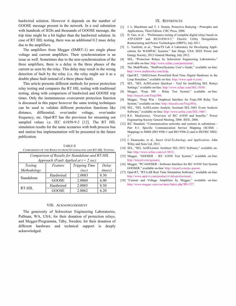
hardwired solution. However it depends on the number of
GOOSE message present in the network. In a real substation
with hundreds of IEDs and thousands of GOOSE message, the
trip time might be a bit higher than the hardwired solution. In
case of RT HIL testing, there was an additional 0.2 msec delay
due to the amplifiers.
The amplifiers from Megger (SMRT-1) are single phase
voltage and current amplifiers. Their synchronization is an
issue as well. Sometimes due to the non-synchronization of the
three amplifiers, there is a delay in the three phases of the
current as seen by the relay. This delay may result in the wrong
detection of fault by the relay (i.e. the relay might see it as a
double phase fault instead of a three phase fault).
This article presents different methods for power protection
relay testing and compares the RT HIL testing with traditional
testing, along with comparison of hardwired and GOOSE trip
times. Only the instantaneous overcurrent protection function
is discussed in this paper however the same testing techniques
can be used to validate different protection functions like
distance, differential, over/under voltage, over/under
frequency, etc. Opal-RT has the provision for streaming out
sampled values i.e. IEC 61850-9-2 [12]. The RT HIL
simulation results for the same scenarios with both process bus
and station bus implementation will be presented in the future
publication.
TABLE II
COMPARISON OF THE RESULTS FROM STANDALONE AND RT-HIL TESTING
Comparison of Results for Standalone and RT-HIL
Approach (Fault Applied at t = 2 sec)
Testing
Methodology
Feature Tripping Time
(sec)
Delay
(msec)
Standalone Hardwired 2.0083 8.30
GOOSE 2.0060 6.00
RT-HIL Hardwired 2.0085 8.50
GOOSE 2.0062 6.20
VIII. ACKNOWLEDGMENT
The generosity of Schweitzer Engineering Laboratories,
Pullman, WA, USA; for their donation of protection relays,
and Megger/Programma, Täby, Sweden; for their donation of
different hardware and technical support is deeply
acknowledged.
IX. REFERENCES
[1] J. L. Blackburn and T. J. Domin, Protective Relaying - Principles and
Applications, Third Edition. CRC Press, 2006.
[2] H. Gao, et al. , “Performance testing of complete digital relays based on
ATP-EMTP and IEC61850-9-2.” Electric Utility Deregulation
Restructuring and Power Technologies (DRPT), July 2011.
[3] L. Vanfretti, et al., “SmarTS Lab A Laboratory for Developing Appli-
cations for WAMPAC Systems.” San Diego, USA: IEEE Power and
Energy Society, 2012 General Meeting, July 2012. [4] SEL, “Protection Relays by Schweitzer Engineering Laboratories,”
avail-able on-line: http://www.selinc.com/protection/.
[5] The MathWorks, “SimPowerSystems User’s Guide,” available on-line:
http://www.mathworks.com/help.
[6] Opal-RT, “eMEGAsim PowerGrid Real-Time Digital Hardware in the
Loop Simulator,” available on-line: http://www.opal-rt.com/.
[7] SEL, “SEL AcSELerator Quickset - Tool for modifying SEL Relays
Settings,” available on-line: http://www.selinc.com/SEL-5030/.
[8] Megger, “Freja 300 - Relay Test System,” available on-line:
http://tinyurl.com/Freja300.
[9] Megger, “Freja Win - Graphical Interface for Freja-300 Relay Test
System,” available on-line: http://tinyurl.com/FrejaWin.
[10] SEL, “SEL AcSELerator Analytic Assistant SEL-5601 Event Analysis
Software,” available on-line: http://www.selinc.com/SEL-5601/.
[11] R.E. Mackiewicz, “Overview of IEC 61850 and benefits.” Power
Engineering Society General Meeting, 2006. IEEE, 2006.
[12] IEC Standard, “Communication networks and systems in substations -
Part 8-1: Specific Communication Service Mapping (SCSM) -
Mappings to MMS (ISO 9506-1 and ISO 9506-2) and to ISO/IEC 8802-
3.”
[13] J. Ekanayake, et al., Smart Grid-Technology and Applications. John
Wiley and Sons Ltd, 2012.
[14] SEL, “SEL AcSELerator Architect SEL-5032 Software,” available on-
line: http://www.selinc.com/sel-5032/.
[15] Megger, “GOOSER - IEC 61850 Test System,” available on-line:
http://tinyurl.com/goosers.
[16] Megger, “PC-GOOSER - Software Interface for IEC 61850 Test System
GOOSER,” available on-line: http://tinyurl.com/pc-gooser.
[17] Opal-RT, “RT-LAB Real Time Simulation Software,” available on-line:
http://www.opal-rt.com/product/rt-lab-professional.
[18] “Current and Voltage Amplifiers by Megger,” available on-line:
http://www.megger.com/cae/story/Index.php?ID=527.